
Acvatix™ Valves VVF..,VXF.., VVG41.., VXG41.., VVI41 ...
94
CE1P4030en 2014-11-18 Building Technologies VVF53.. VXF53.. VVG41.. VXG41.. Acvatix™ Valves VVF..,VXF.., VVG41.., VXG41.., VVI41.., VXI41.. Basic Documentation - Version changes
Transcript of Acvatix™ Valves VVF..,VXF.., VVG41.., VXG41.., VVI41 ...

CE1P4030en2014-11-18 Building Technologies
VVF53.. VXF53..VVG41.. VXG41..
Acvatix™Valves VVF..,VXF.., VVG41.., VXG41.., VVI41.., VXI41..Basic Documentation - Version changes

2 / 94
Siemens Valves VVF..,VXF.., VVG41.., VXG41.., VVI41.., VXI41.. CE1P4030enBuilding Technologies 2014-11-18
Siemens Switzerland Ltd.Building Technologies DivisionInternational HeadquartersGubelstrasse 226301 ZugSwitzerlandPhone +41 41-724 24 24www.siemens.com/sbt
© Siemens Switzerland Ltd., 2011.Subject to change

3 / 94
Siemens Valves VVF..,VXF.., VVG41.., VXG41.., VVI41.., VXI41.. CE1P4030enBuilding Technologies Table of contents 2014-11-18
Table of contents1 About this document ........................................................................... 61.1 Navigation ............................................................................................. 61.2 Revision history ..................................................................................... 61.3 Reference documents ............................................................................ 6
1.3.1 2- and 3-port valves with flanged connections ................................... 61.3.2 2- and 3-port valves with threaded connections ................................. 61.3.3 2- port valves with flanged connections and pressure compensation . 7
1.4 Before you start ..................................................................................... 71.4.1 Trademarks ...................................................................................... 71.4.2 Copyright .......................................................................................... 71.4.3 Quality assurance ............................................................................. 71.4.4 Document use / request to the reader ............................................... 8
1.5 Validity of documentation ....................................................................... 8
2 Engineering .......................................................................................... 92.1 Product description ................................................................................ 9
2.1.1 2-port valves ..................................................................................... 92.1.2 3-port valves ................................................................................... 102.1.3 Type plate ....................................................................................... 11
2.2 Use ...................................................................................................... 122.2.1 Compatibility with medium and temperature ranges......................... 122.2.2 Fields of use ................................................................................... 13
2.3 Type summary and equipment combinations ........................................ 142.3.1 2-port valves with flanged connections ............................................ 142.3.2 2- port valves with threaded connections ......................................... 192.3.3 2- port valves with flanged connections and pressure compensation212.3.4 3-port valves with flanged connections ............................................ 222.3.5 3- port valves with threaded connections ......................................... 262.3.6 Overview of actuators ..................................................................... 27
2.4 Ordering .............................................................................................. 282.5 Accessories ......................................................................................... 28
2.5.1 Electrical accessories ..................................................................... 282.5.2 Mechanical accessories .................................................................. 282.5.3 Adapters ......................................................................................... 292.5.4 Fittings ............................................................................................ 30
2.6 Product replacement ............................................................................ 302.6.1 2-port valves ................................................................................... 312.6.2 3-port valves ................................................................................... 322.6.3 Accessories .................................................................................... 33
2.7 Spare parts .......................................................................................... 332.8 Valve sizing for fluids (water, heat transfer oil) ...................................... 35
2.8.1 Procedure for valve sizing ............................................................... 352.8.2 Flow chart ....................................................................................... 362.8.3 Impact of fluid properties on valve sizing ......................................... 36
2.8.3.1 Density ρ .................................................................................. 372.8.3.2 Specific heat capacity c ............................................................ 372.8.3.3 Kinematic viscosity ν ................................................................ 38
2.8.4 Influencing factors with selected groups of fluids ............................. 392.8.5 Rangeability Sv, minimum controllable output Qmin ........................... 40
2.9 Sizing valves for steam ........................................................................ 40

4 / 94
Siemens Valves VVF..,VXF.., VVG41.., VXG41.., VVI41.., VXI41.. CE1P4030enBuilding Technologies Table of contents 2014-11-18
2.10 Calculation examples for water, heat transfer oil and steam ................. 432.10.1 Example for water: Heater with pressure and variable volumetric flow432.10.2 Example for water: Heater with low differential pressure without main
pump .............................................................................................. 442.10.3 Example for heat transfer oil ........................................................... 452.10.4 Example for steam .......................................................................... 47
2.11 Valve characteristics ............................................................................ 492.11.1 2-port valves ................................................................................... 492.11.2 3-port valves ................................................................................... 49
2.12 Operating pressure and medium temperature ...................................... 502.12.1 ISO 7005 and EN 1092 – a comparison .......................................... 502.12.2 PN 6 valves with flanged connections ............................................. 512.12.3 PN 10 valves with flanged connections ........................................... 512.12.4 PN 16 valves with flanged connections ........................................... 522.12.5 PN 25 valves with flanged connections ........................................... 532.12.6 PN 16 valves with threaded connections ......................................... 54
2.13 Cavitation ............................................................................................ 562.14 Medium quality and medium treatment ................................................. 57
2.14.1 Water .............................................................................................. 572.14.2 Water with antifreeze ...................................................................... 582.14.3 Deionized, demineralized water and super-clean water ................... 592.14.4 Heat transfer oil (thermal oil) ........................................................... 60
2.15 Engineering notes ................................................................................ 612.15.1 Strainer (dirt trap) ............................................................................ 612.15.2 Avoiding flow noise ......................................................................... 612.15.3 Avoiding false circulation ................................................................. 612.15.4 Thermal insulation .......................................................................... 62
2.16 Warranty .............................................................................................. 63
3 Handling ............................................................................................. 643.1 Mounting and installation ..................................................................... 64
3.1.1 Mounting positions .......................................................................... 643.1.2 Direction of flow for fluids and steam ............................................... 643.1.3 Flanges .......................................................................................... 653.1.4 Stem heating element ASZ6.6 ......................................................... 673.1.5 Thermal insulation .......................................................................... 67
3.2 Commissioning and maintenance ........................................................ 683.2.1 Commissioning ............................................................................... 683.2.2 Maintenance ................................................................................... 68
3.3 Disposal .............................................................................................. 68
4 Functions and control ....................................................................... 694.1 Selection of acting direction and valve characteristic ............................ 694.2 Calibration ........................................................................................... 704.3 Technical and mechanical design ......................................................... 70
4.3.1 Vales with pressure compensation .................................................. 714.3.2 Plug stop ........................................................................................ 714.3.3 Valve stem, valve neck, coupling ..................................................... 714.3.4 Converting a 2-port to a 3-port valve ............................................... 714.3.5 Converting a 3-port to a 2-port valve ............................................... 724.3.6 Flange types ................................................................................... 72
5 Technical data .................................................................................... 73

5 / 94
Siemens Valves VVF..,VXF.., VVG41.., VXG41.., VVI41.., VXI41.. CE1P4030enBuilding Technologies Table of contents 2014-11-18
6 Dimensions ........................................................................................ 76
7 Revision numbers .............................................................................. 84
8 Addendum .......................................................................................... 868.1.1 Abbreviations .................................................................................. 868.1.2 Important formulas .......................................................................... 878.1.3 Valve-related glossary ..................................................................... 878.1.4 Hydraulics-related glossary ............................................................. 888.1.5 Media-related glossary .................................................................... 898.1.6 Trade names................................................................................... 898.1.7 Overview of antifreeze and brines used in the trade ........................ 89

6 / 94
Siemens Valves VVF..,VXF.., VVG41.., VXG41.., VVI41.., VXI41.. CE1P4030enBuilding Technologies About this document 2014-11-18
1 About this document1.1 Navigation
You will find information about a specific valve throughout the document. Thestructure of chapters 2 to 4 is as follows:
2 Engineering device oriented3 Handling process oriented
3.1 Mounting and installation3.2 Commissioning and maintenance3.3 ...
4 Functions and control assembly oriented4.1 Selection of acting direction and valve characteristic4.2 Calibration4.3 ...
1.2 Revision historyRevision Date Changes Chapter Page(s)
First edition 2011-09-11 - - -
Rev. 2 2014-02-03 VVF/VXF22/32/42 implementedVVF43/53..K implemented all -
Revision 2.1 2014-11-18 Änderungen VVF43/53..K
2.1.3, 2.3.3,2.6.1-2.6.3,2.7, 2.9, 2.11,2.12.4-2.12.6,3.1.2, 4.3.6, 6,7
-
1.3 Reference documents1.3.1 2- and 3-port valves with flanged connections
Type of document VVF22..VXF22..
VVF32..VXF32..
VVF42..VXF42..
VVF43..VXF43..
VVF53..VXF53..
Data Sheet N4401 N4402 N4403 N4404 N4405
Mounting Instructions M4030 M4030 M4030 M4030 M4030
CE Declaration of Conformity (PED) - T4030 T4030 T4030 T4030
Environmental Declaration E4401 E4402 E4403 E4404 E4405
1.3.2 2- and 3-port valves with threaded connections
Type of document VVG41.. VXG41.. VVI41.. / VXI41..
Data Sheet N4363 N4464 N4362
Mounting Instructions M4363 M4363 M4362
CE Declaration of Conformity (PED) - - -
Environmental Declaration E4363 E4363 E4362
7 / 94
Siemens Valves VVF..,VXF.., VVG41.., VXG41.., VVI41.., VXI41.. CE1P4030enBuilding Technologies About this document 2014-11-18
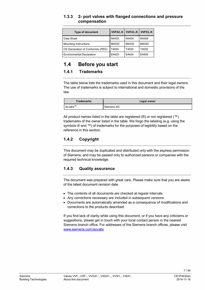
1.3.3 2- port valves with flanged connections and pressurecompensation
Type of document VVF42..K VVF43..K VVF53..K
Data Sheet N4403 N4404 N4405
Mounting Instructions M4030 M4030 M4030
CE Declaration of Conformity (PED) T4030 T4030 T4030
Environmental Declaration E4403 E4404 E4405
1.4 Before you start1.4.1 Trademarks
The table below lists the trademarks used in this document and their legal owners.The use of trademarks is subject to international and domestic provisions of thelaw.
Trademarks Legal owner
AcvatixTM Siemens AG
All product names listed in the table are registered (®) or not registered (™)trademarks of the owner listed in the table. We forgo the labeling (e.g. using thesymbols ® and ™) of trademarks for the purposes of legibility based on thereference in this section.
1.4.2 Copyright
This document may be duplicated and distributed only with the express permissionof Siemens, and may be passed only to authorized persons or companies with therequired technical knowledge.
1.4.3 Quality assurance
The document was prepared with great care. Please make sure that you are awareof the latest document revision date.
· The contents of all documents are checked at regular intervals· Any corrections necessary are included in subsequent versions· Documents are automatically amended as a consequence of modifications and
corrections to the products described
If you find lack of clarity while using this document, or if you have any criticisms orsuggestions, please get in touch with your local contact person in the nearestSiemens branch office. For addresses of the Siemens branch offices, please visitwww.siemens.com/acvatix

8 / 94
Siemens Valves VVF..,VXF.., VVG41.., VXG41.., VVI41.., VXI41.. CE1P4030enBuilding Technologies About this document 2014-11-18
1.4.4 Document use / request to the reader
Before using our products, it is important that you read the documents suppliedwith or ordered at the same time as the products (equipment, applications, tools,etc.) carefully and in full.
We assume that persons using our products and documents are authorized andtrained appropriately and have the technical knowledge required to use ourproducts as intended.
More information on the products and applications is available:
· On the intranet (Siemens employees only) athttps://workspace.sbt.siemens.com/content/00001123/default.aspx.
· From the Siemens branch office near you or from your system supplier· From the Support Team at headquarters ([email protected])
if there is no local point of contact
Siemens assumes no liability to the extent allowed under the law for any lossesresulting from a failure to comply with the aforementioned points or for impropercompliance of the same.
1.5 Validity of documentation
This document shall serve as a knowledge base. In addition to basic knowledge, itprovides general technical information about valves used in HVAC plants.
For project engineers, electrical HVAC planners, system integrators, and serviceengineers, the document contains all information required for planning,engineering, correct installation, commissioning, and servicing.
9 / 94
Siemens Valves VVF..,VXF.., VVG41.., VXG41.., VVI41.., VXI41.. CE1P4030enBuilding Technologies Engineering 2014-11-18
2 Engineering2.1 Product description
The large-stroke valve line consists of 2-port and 3-port valves.
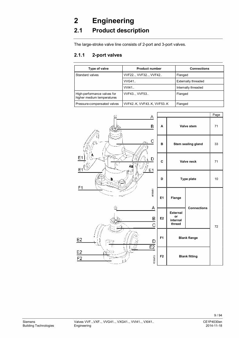
2.1.1 2-port valves
Type of valve Product number Connections
Standard valves VVF22.., VVF32.., VVF42.. Flanged
VVG41.. Externally threaded
VVI41.. Internally threaded
High-performance valves forhigher medium temperatures
VVF43.., VVF53.. Flanged
Pressure-compensated valves VVF42..K, VVF43..K, VVF53..K Flanged
Page
A Valve stem 71
B Stem sealing gland 33
C Valve neck 71
D Type plate 10
E1 Flange
Connections
72
E2
Externalor
internalthread
F1 Blank flange
F2 Blank fitting
10 / 94
Siemens Valves VVF..,VXF.., VVG41.., VXG41.., VVI41.., VXI41.. CE1P4030enBuilding Technologies Engineering 2014-11-18
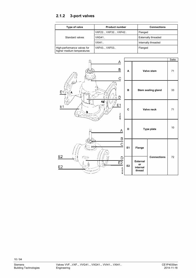
2.1.2 3-port valves
Type of valve Product number Connections
Standard valves
VXF22.., VXF32.., VXF42.. Flanged
VXG41.. Externally threaded
VXI41.. Internally threaded
High-performance valves forhigher medium temperatures
VXF43.., VXF53.. Flanged
Seite
A Valve stem 71
B Stem sealing gland 33
C Valve neck 71
D Type plate 10
E1 Flange
Connections 72
E2External
orinternalthread

11 / 94
Siemens Valves VVF..,VXF.., VVG41.., VXG41.., VVI41.., VXI41.. CE1P4030enBuilding Technologies Engineering 2014-11-18
2.1.3 Type plate1 Flow direction for fluids2 Flow direction for steam
Port markings are cast integral3 Product number4 Stock number5 Nominal pressure class6 Nominal size7 kvs value8 Serial number9 Country of origin10 CE mark conforming to PED 97/23/EC.
Applies only to valves of category I or IIconforming to PED 97/23/EC
11 Notified body number for monitoringproduction centers as per module A1 ofPED 97/23/EC. Applies only to valves ofcategory II
Fluids Steam
QR code (Siemens in-house usage)
1 Flow directionPort markings are cast integral
2 Product number3 Stock number4 Nominal pressure class5 Nominal size6 kvs value7 Serial number8 Country of origin9 CE mark conforming to PED 97/23/EC10 Notified body number for monitoring
production centers as per module A1 ofPED 97/23/EC.
Applies only to valves of category II QR code (Siemens in-house usage)
1 Flow direction for fluidsPort markings are cast integral
2 Product number3 Stock number4 Nominal pressure class5 Nominal size6 kvs value7 Serial number8 Country of origin9 CE mark conforming to PED 97/23/EC.
Applies only to valves of category I or IIconforming to PED 97/23/EC
10 Notified body number for monitoringproduction centers as per module A1 ofPED 97/23/EC. Applies only to valves ofcategory II
QR code (Siemens in-house usage)
2-port valves
2-port valvesVVF43..KVVF53..K
3-port valves
12 / 94
Siemens Valves VVF..,VXF.., VVG41.., VXG41.., VVI41.., VXI41.. CE1P4030enBuilding Technologies Engineering 2014-11-18
2.2 Use
The valves are used as control or shutoff valves in heating, ventilation and airconditioning plants for the production and distribution of heat or cooling energy, aswell as in district heating plants and in steam applications.
All 3-port valves can be used as mixing valves (preferred use) or diverting valves.For use in closed or open hydraulic circuits, observe chapter "Cavitation", page 56.
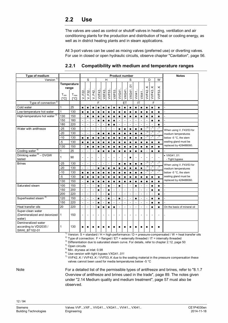
2.2.1 Compatibility with medium and temperature ranges
Type of medium Product number NotesVersion 1) S H S D W
Temperaturerange
V..F
22..
V..F
32..
V..F
42..
VV
F43.
.V
XF4
3..
VV
F53.
.
VX
F53.
.
VV
G41
..
VX
G41
..
VX
G41
..01
VV
I41.
.
VX
I41.
.
VV
F42.
.K
VV
F43.
.K
VV
F53.
.K
Tmin
[°C]Tmax
[°C]Type of connection 2) F ET IT F -
Cold water 1 25 ■ ■ ■ ■ ■ ■ ■ ■ ■ ■ ■ ■ ■ ■ ■ -Low-temperature hot water 1 130 ■ ■ ■ ■ ■ ■ ■ ■ ■ ■ ■ ■ ■ ■ ■ -High-temperature hot water 3) 130 150 - ■ ■ ■ ■ ■ ■ ■ ■ ■ ■ ■ ■ ■ ■ -
150 180 - - - ■ ■ ■ ■ - - - - - - ■ ■ -180 220 - - - - - ■ ■ - - - - - - - ■ -
Water with antifreeze -25 130 - - - - - - - ■ ■ ■ ■ ■ -7) -7) -7)When using V..F43/53 formedium temperaturesbelow -5 °C, the stemsealing gland must bereplaced by 428488060.
-20 130 - - - ■ ■ ■ ■ ■ ■ ■ ■ ■ -7) -7) -7)
-10 130 ■ ■ ■ ■ ■ ■ ■ ■ ■ ■ ■ ■ -7) -7) -7)
-5 130 ■ ■ ■ ■ ■ ■ ■ ■ ■ ■ ■ ■ ■ ■ ■130 150 - ■ ■ ■ ■ ■ ■ ■ ■ ■ ■ ■ ■ ■ ■
Cooling water 4) 1 25 - - - ■ ■ ■ ■ ■ ■ ■ ■ ■ - ■ ■ -Drinking water 6) – DVGWtested 1 90 - - - - - - - - - ■ - - - - - · VXG41..01:
- Tight bypassBrines -25 130 - - - - - - - ■ ■ ■ ■ ■ -7) -7) -7)
When using V..F43/53 formedium temperaturesbelow -5 °C, the stemsealing gland must bereplaced by 428488060.
-20 130 - - - ■ ■ ■ ■ ■ ■ ■ ■ ■ -7) -7) -7)
-10 130 ■ ■ ■ ■ ■ ■ ■ ■ ■ ■ ■ ■ -7) -7) -7)
-5 130 ■ ■ ■ ■ ■ ■ ■ ■ ■ ■ ■ ■ ■ ■ ■130 150 - ■ ■ ■ ■ ■ ■ ■ ■ ■ ■ ■ ■ ■ ■
Saturated steam 100 150 - - - ■ - ■ - ■ - - ■ - - ■ ■ -150 200 - - - ■ - ■ - - - - - - - ■ ■ -200 220 - - - - - ■ - - - - - - - - ■ -
Superheated steam 5) 120 150 - - - ■ - ■ - ■ - - ■ - - ■ ■ -150 220 - - - ■ - ■ - - - - - - - ■ ■ -
Heat transfer oils 20 220 - - - ■ ■ ■ ■ - - - - - - ■ ■ On the basis of mineral oilSuper-clean water(Demineralized and deionizedwater)
1 150 - - - - - - - - - - - - - - - -
Demineralized wateraccording to VDI2035 /SWKI_BT102-01
1 130 ■ ■ ■ ■ ■ ■ ■ ■ ■ ■ ■ ■ ■ ■ ■
1) Version: S = standard / H = high-performance / D = pressure-compensated / W = heat transfer oils2) Type of connection: F = flanged / ET = externally threaded / IT = internally threaded3) Differentiation due to saturated steam curve. For details, refer to chapter 2.12, page 504) Open circuits5) Min. dryness at inlet: 0.986) Use version with tight bypass VXG41..01!7) VVF42..K / VVF43..K / VVF53..K due to the sealing material in the pressure compensation these
valves cannot been used for media temperatures below -5 °C
For a detailed list of the permissible types of antifreeze and brines, refer to "8.1.7Overview of antifreeze and brines used in the trade", page 89. The notes givenunder "2.14 Medium quality and medium treatment", page 57 must also beobserved.
Note
13 / 94
Siemens Valves VVF..,VXF.., VVG41.., VXG41.., VVI41.., VXI41.. CE1P4030enBuilding Technologies Engineering 2014-11-18
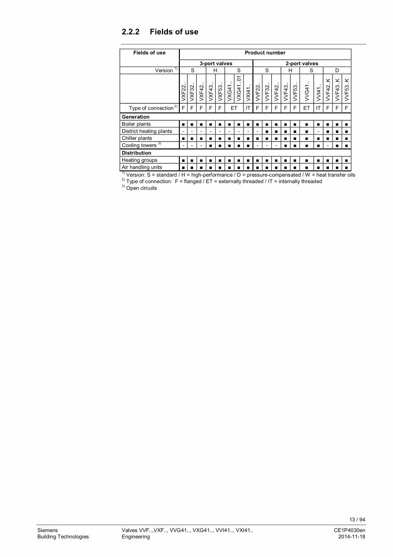
2.2.2 Fields of use
Fields of use Product number
3-port valves 2-port valvesVersion 1) S H S S H S D
VX
F22.
.V
XF3
2..
VX
F42.
.
VX
F43.
.
VX
F53.
.
VX
G41
..
VX
G41
..01
VX
I41.
.
VV
F22.
.
VV
F32.
.
VV
F42.
.
VV
F43.
.
VV
F53.
.
VV
G41
..
VV
I41.
.
VV
F42.
.K
VV
F43.
.K
VV
F53.
.K
Type of connection 2) F F F F F ET IT F F F F F ET IT F F F
GenerationBoiler plants ■ ■ ■ ■ ■ ■ ■ ■ ■ ■ ■ ■ ■ ■ ■ ■ ■ ■District heating plants - - - - - - - - - ■ ■ ■ ■ ■ - ■ ■ ■Chiller plants ■ ■ ■ ■ ■ ■ ■ ■ ■ ■ ■ ■ ■ ■ ■ ■ ■ ■Cooling towers 3) - - - ■ ■ ■ ■ ■ - - - ■ ■ ■ ■ - ■ ■DistributionHeating groups ■ ■ ■ ■ ■ ■ ■ ■ ■ ■ ■ ■ ■ ■ ■ ■ ■ ■Air handling units ■ ■ ■ ■ ■ ■ ■ ■ ■ ■ ■ ■ ■ ■ ■ ■ ■ ■1) Version: S = standard / H = high-performance / D = pressure-compensated / W = heat transfer oils2) Type of connection: F = flanged / ET = externally threaded / IT = internally threaded3) Open circuits
14 / 94
Siemens Valves VVF..,VXF.., VVG41.., VXG41.., VVI41.., VXI41.. CE1P4030enBuilding Technologies Engineering 2014-11-18
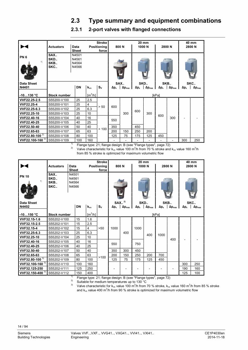
2.3 Type summary and equipment combinations2.3.1 2-port valves with flanged connections
Stroke 20 mm 40 mmActuators Data
SheetPositioning
force800 N 1000 N 2800 N 2800 N
PN 6 SAX.. N4501SKD.. N4561
1) SKB.. N4564SKC.. N4566
Data Sheet SAX.. SKD.. SKB.. SKC..N4401 DN kvs SV Δps Δpmax Δps Δpmax Δps Δpmax Δps Δpmax
-10…130 °C Stock number [m3/h] [kPa]VVF22.25-2.5 S55200-V100 25 2.5
> 50 600
300600
300600
300 - -
VVF22.25-4 S55200-V101 25 4VVF22.25-6.3 S55200-V102 25 6.3VVF22.25-10 S55200-V103 25 10VVF22.40-16 S55200-V104 40 16
> 100
550VVF22.40-25 S55200-V105 40 25VVF22.50-40 S55200-V106 50 40 350 450VVF22.65-63 S55200-V107 65 63 200 150 250 200VVF22.80-100 2) S55200-V108 80 100 125 75 175 125 450VVF22.100-160 2) S55200-V109 100 160 - - - - - - 300 250
1) Flange type: 21; flange design: B (see "Flange types", page 72)2) Valve characteristic for kvs value 100 m3/h from 70 % stroke and kvs value 160 m3/h
from 85 % stroke is optimized for maximum volumetric flow
Stroke 20 mm 40 mmActuators Data
SheetPositioning
force800 N 1000 N 2800 N 2800 N
PN 10 SAX.. N4501SKD.. N4561
1) SKB.. N4564SKC.. N4566
Data Sheet SAX.. 2) SKD.. SKB.. SKC..N4402 DN kvs SV Δps Δpmax Δps Δpmax Δps Δpmax Δps Δpmax
-10…150 °C Stock number [m3/h] [kPa]VVF32.15-1.6 S55202-V100 15 1.6
>50 1000400
1000
400 1000400 - -
VVF32.15-2.5 S55202-V101 15 2.5VVF32.15-4 S55202-V102 15 4VVF32.25-6.3 S55202-V103 25 6.3VVF32.25-10 S55202-V104 25 10VVF32.40-16 S55202-V105 40 16
>100
550 750VVF32.40-25 S55202-V106 40 25VVF32.50-40 S55202-V107 50 40 350 300 450VVF32.65-63 S55202-V108 65 63 200 150 250 200 700VVF32.80-100 3) S55202-V109 80 100 125 75 175 125 450VVF32.100-160 3) S55202-V110 100 160
- - - - - -300 250
VVF32.125-250 S55202-V111 125 250 190 160VVF32.150-400 3) S55202-V112 150 400 125 100
1) Flange type: 21; flange design: B (see "Flange types", page 72)2) Suitable for medium temperatures up to 130 °C3) Valve characteristic for kvs value 100 m3/h from 70 % stroke, kvs value 160 m3/h from 85 % stroke
and kvs value 400 m3/h from 90 % stroke is optimized for maximum volumetric flow

15 / 94
Siemens Valves VVF..,VXF.., VVG41.., VXG41.., VVI41.., VXI41.. CE1P4030enBuilding Technologies Engineering 2014-11-18
Stroke 20 mm 40 mmActuators Data
SheetPositioning
force800 N 1000 N 2800 N 2800 N
PN 16 SAX.. N4501SKD.. N4561
Productphoto – tobe created
1) SKB.. N4564SKC.. N4566
Data Sheet SAX.. 2) SKD.. SKB.. SKC..N4403 DN kvs SV Δps Δpmax Δps Δpmax Δps Δpmax Δps Δpmax
-10…150 °C Stock number [m3/h] [kPa]VVF42.15-1.6 S55204-V100 15 1.6
> 50 1600
400
1600
4001600
400 - -
VVF42.15-2,5 S55204-V101 15 2.5VVF42.15-4 S55204-V102 15 4VVF42.20-6.3 S55204-V103 20 6.3VVF42.25-6.3 S55204-V104 25 6.3VVF42.25-10 S55204-V105 25 10VVF42.32-16 S55204-V106 32 16
> 100
900 1200VVF42.40-16 S55204-V107 40 16
550 750VVF42.40-25 S55204-V108 40 25VVF42.50-31.5 S55204-V109 50 31.5
350 300 450 1200VVF42.50-40 S55204-V110 50 40VVF42.65-50 S55204-V111 65 50
200 150 250 200 700VVF42.65-63 S55204-V112 65 63VVF42.80-80 S55204-V113 80 80
125 75 175 125 450VVF42.80-1003) S55204-V114 80 100VVF42.100-125 S55204-V115 100 125
- - - - - -
300 250VVF42.100-1603) S55204-V116 100 160VVF42.125-200 S55204-V117 125 200
190 160VVF42.125-250 S55204-V118 125 250VVF42.150-315 S55204-V119 150 315
125 100VVF42.150-4003) S55204-V120 150 4001) Flange type: 21; flange design: B (see "Flange types", page 72)2) Suitable for medium temperatures up to 130 °C3) Valve characteristic for kvs value 100 m3/h from 70 % stroke, kvs value 160 m3/h from 85 % stroke
and kvs value 400 m3/h from 90 % stroke is optimized for maximum volumetric flow

16 / 94
Siemens Valves VVF..,VXF.., VVG41.., VXG41.., VVI41.., VXI41.. CE1P4030enBuilding Technologies Engineering 2014-11-18
Stroke 20 mm 40 mmActuators Data
SheetPositioning
force800 N 1000 N 2800 N 2800 N
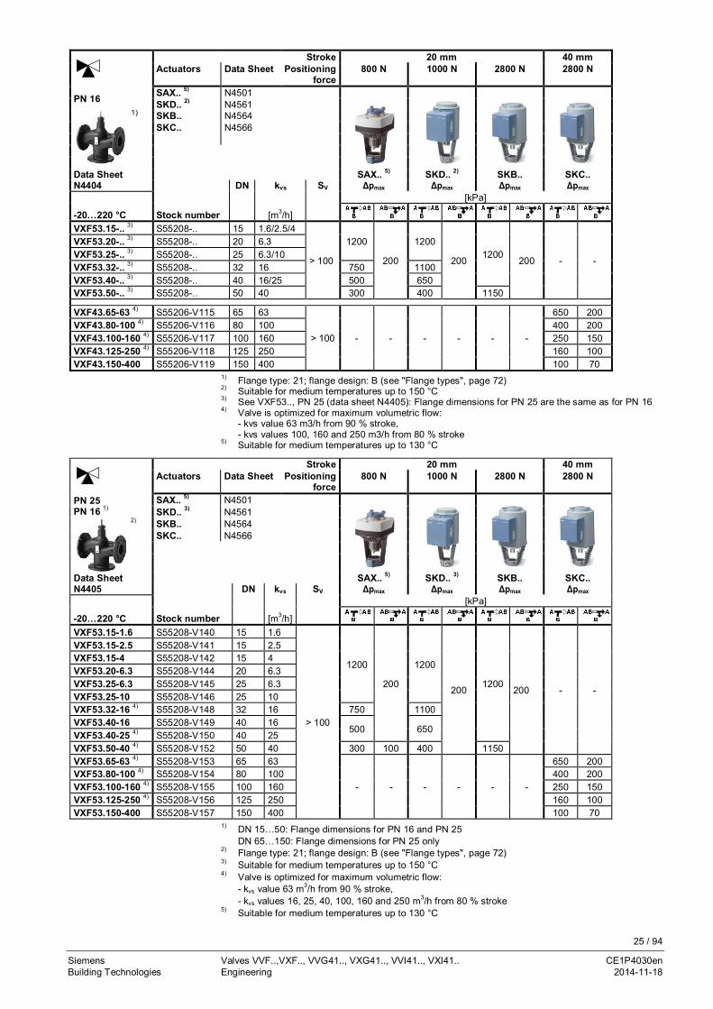
PN 16 SAX.. 5) N4501SKD.. 2) N4561
1) SKB.. N4564SKC.. N4566
Data Sheet SAX.. 5) SKD.. 2) SKB.. SKC..N4404 DN kvs SV Δps Δpmax Δps Δpmax Δps Δpmax Δps Δpmax
-20…220 °C Stock number [m3/h] [kPa]VVF53.15-.. 3) S55208-.. 15 0.16…1.25 > 50
25001200
25001200
25001200
- -
VVF53.15-.. 3) S55208-.. 15 1.6…4
> 100
VVF53.20-.. 3) S55208-.. 20 6.3VVF53.25-.. 3) S55208-.. 25 5…10 1600 2100VVF53.32-.. 3) S55208-.. 32 16 900 750 1200 1100VVF53.40-.. 3) S55208-.. 40 12.5…25 550 500 750 650 2000VVF53.50-.. 3) S55208-.. 50 31.5…40 350 300 450 400 1200 1150
VVF43.65-50 S55206-V10065
50
> 100 - - - - - -
700 650VVF43.65-63 4) S55206-V101 63VVF43.80-80 S55206-V102
8080
450 400VVF43.80-100 4) S55206-V103 100VVF43.100-125 S55206-V104
100125
300 250VVF43.100-160 4) S55206-V105 160VVF43.125-200 4) S55206-V106
125200
190 160VVF43.125-250 4) S55206-V107 250VVF43.150-315 4) S55206-V108
150315
125 100VVF43.150-400 S55206-V109 4001) Flange type: 21; flange design: B (see "Flange types", page 72)2) Suitable for medium temperatures up to 150 °C3) See VVF53.., PN 25 (Data Sheet N4405): Flange dimensions for PN 25 are the same as those for
PN 164) Valve characteristic is optimized for maximum volumetric flow:
- kvs value 63 m3/h from 90 % stroke,- kvs values 100, 160, 200 and 250 m3/h from 80 % stroke,- kvs value 315 m3/h from 70 % stroke
5) Suitable for medium temperatures up to 130 °C
For applications with steam the maximum differential and closing pressures differfrom the values above. For further details refer to “Applications with steam” onpage 18.
Note
17 / 94
Siemens Valves VVF..,VXF.., VVG41.., VXG41.., VVI41.., VXI41.. CE1P4030enBuilding Technologies Engineering 2014-11-18
Stroke 20 mm 40 mmActuators Data
SheetPositioning
force800 N 1000 N 2800 N 2800 N
PN 25PN 16 1)
SAX.. 5) N4501SKD.. 3) N4561
2) SKB.. N4564SKC.. N4566
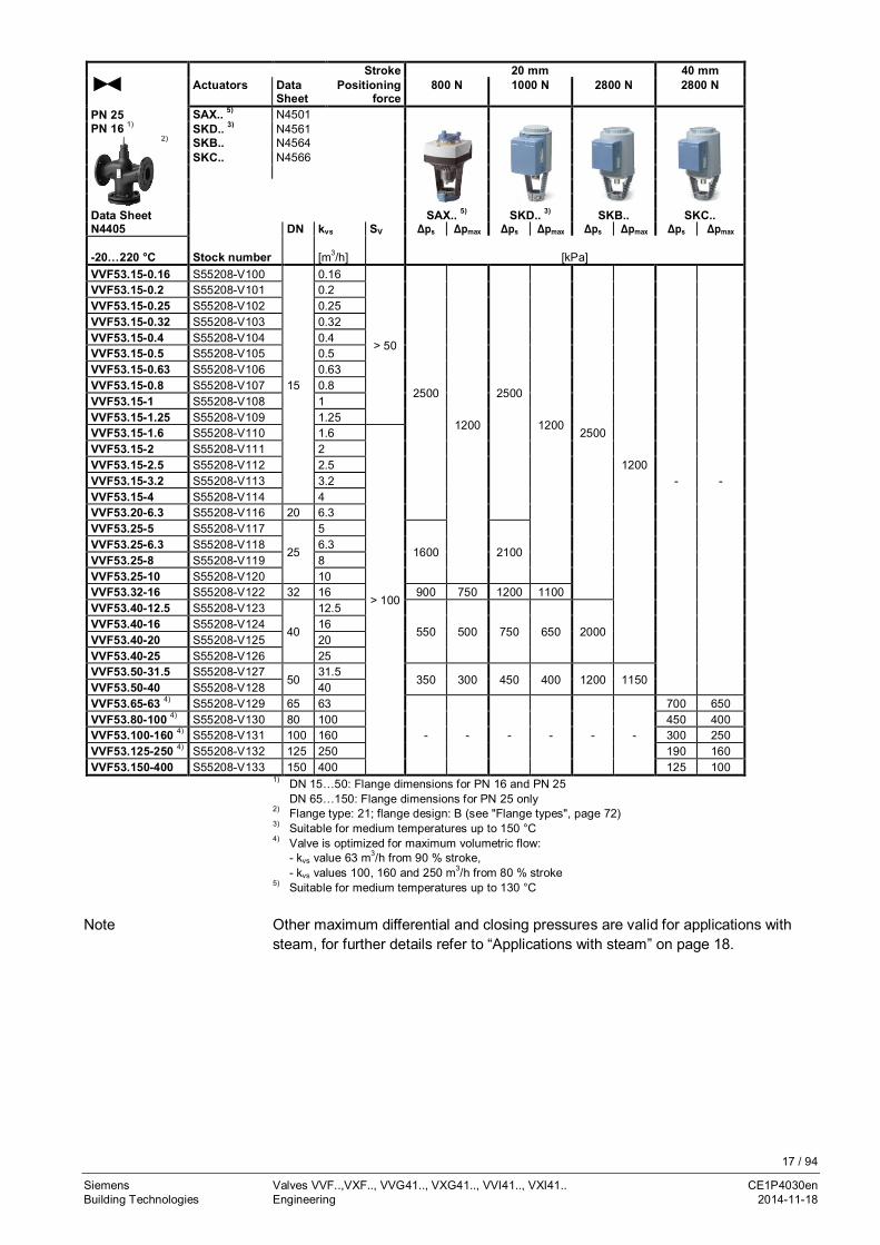
Data Sheet SAX.. 5) SKD.. 3) SKB.. SKC..N4405 DN kvs SV Δps Δpmax Δps Δpmax Δps Δpmax Δps Δpmax
-20…220 °C Stock number [m3/h] [kPa]VVF53.15-0.16 S55208-V100
15
0.16
> 50
2500
1200
2500
12002500
1200- -
VVF53.15-0.2 S55208-V101 0.2VVF53.15-0.25 S55208-V102 0.25VVF53.15-0.32 S55208-V103 0.32VVF53.15-0.4 S55208-V104 0.4VVF53.15-0.5 S55208-V105 0.5VVF53.15-0.63 S55208-V106 0.63VVF53.15-0.8 S55208-V107 0.8VVF53.15-1 S55208-V108 1VVF53.15-1.25 S55208-V109 1.25VVF53.15-1.6 S55208-V110 1.6
> 100
VVF53.15-2 S55208-V111 2VVF53.15-2.5 S55208-V112 2.5VVF53.15-3.2 S55208-V113 3.2VVF53.15-4 S55208-V114 4VVF53.20-6.3 S55208-V116 20 6.3VVF53.25-5 S55208-V117
25
5
1600 2100VVF53.25-6.3 S55208-V118 6.3VVF53.25-8 S55208-V119 8VVF53.25-10 S55208-V120 10VVF53.32-16 S55208-V122 32 16 900 750 1200 1100VVF53.40-12.5 S55208-V123
40
12.5
550 500 750 650 2000VVF53.40-16 S55208-V124 16VVF53.40-20 S55208-V125 20VVF53.40-25 S55208-V126 25VVF53.50-31.5 S55208-V127
5031.5
350 300 450 400 1200 1150VVF53.50-40 S55208-V128 40VVF53.65-63 4) S55208-V129 65 63
- - - - - -
700 650VVF53.80-100 4) S55208-V130 80 100 450 400VVF53.100-160 4) S55208-V131 100 160 300 250VVF53.125-250 4) S55208-V132 125 250 190 160VVF53.150-400 S55208-V133 150 400 125 100
1) DN 15…50: Flange dimensions for PN 16 and PN 25DN 65…150: Flange dimensions for PN 25 only
2) Flange type: 21; flange design: B (see "Flange types", page 72)3) Suitable for medium temperatures up to 150 °C4) Valve is optimized for maximum volumetric flow:
- kvs value 63 m3/h from 90 % stroke,- kvs values 100, 160 and 250 m3/h from 80 % stroke
5) Suitable for medium temperatures up to 130 °C
Other maximum differential and closing pressures are valid for applications withsteam, for further details refer to “Applications with steam” on page 18.
Note

18 / 94
Siemens Valves VVF..,VXF.., VVG41.., VXG41.., VVI41.., VXI41.. CE1P4030enBuilding Technologies Engineering 2014-11-18
Valves of the product lines VVF43.. and VVF53.. have to be operated withinverted flow direction for steam. This results in combination withelectrohydraulic actuators of the product lines SKD.., SKB.. und SKC.. withsignificantly higher closing pressures Δps and higher maximum differentialpressures Δpmax. In individual cases the kvs value is reduced and it has to beassured from the system side, when the system is starting up that the maximumdifferential pressure Δpmax is not exceeded so that the actuator can reliably openthe valve.
SteamStroke 20 mm 40 mm
Actuators DataSheet
Positioningforce
800 N 1000 N 2800 N 2800 N
PN 25PN 16 1)
SAX.. 5) N4501SKD.. 3) N4561
2) SKB.. N4564SKC.. N4566
Data Sheet SAX.. 5) SKD.. 3) SKB.. SKC..N4405 DN kvs SV Δps Δpmax Δps Δpmax Δps Δpmax Δps Δpmax
+100…220 °C Stock number [m3/h] [kPa]VVF53.15-0.16 S55208-V100
15
0.16
> 50
- -
2500
1200
2500 1200 - -
VVF53.15-0.2 S55208-V101 0.2VVF53.15-0.25 S55208-V102 0.25VVF53.15-0.32 S55208-V103 0.32VVF53.15-0.4 S55208-V104 0.4VVF53.15-0.5 S55208-V105 0.5VVF53.15-0.63 S55208-V106 0.63VVF53.15-0.8 S55208-V107 0.8VVF53.15-1 S55208-V108 1VVF53.15-1.25 S55208-V109 1.25VVF53.15-1.6 S55208-V110 1.6VVF53.15-2 S55208-V111 2
> 100
VVF53.15-2.5 S55208-V112 2.5VVF53.15-3.2 S55208-V113 3.2VVF53.15-4 4) S55208-V114 3.6VVF53.20-6.3 4) S55208-V116 20 5VVF53.25-5 S55208-V117
25
5VVF53.25-6.3 S55208-V118 6.3VVF53.25-8 S55208-V119 8VVF53.25-10 4) S55208-V120 8VVF53.32-16 4) S55208-V122 32 15VVF53.40-12.5 S55208-V123
40
12.5
1000VVF53.40-16 S55208-V124 16VVF53.40-20 S55208-V125 20VVF53.40-25 4) S55208-V126 23VVF53.50-31.5 S55208-V127
5031.5
600VVF53.50-40 S55208-V128 40VVF53.65-63 S55208-V129 65 63
- - - - 2500
1000VVF53.80-100 S55208-V130 80 100 750VVF53.100-160 4) S55208-V131 100 150 500VVF53.125-250 4) S55208-V132 125 220 300VVF53.150-400 S55208-V133 150 360 200
1) DN 15…50: Flange dimensions for PN 16 and PN 25DN 65…150: Flange dimensions for PN 25 only
2) Flange type: 21; flange design: B (see "Flange types", page 72)3) Suitable for medium temperatures up to 150 °C4) Reduced kvs value5) Suitable for medium temperatures up to 130 °C
Applications with steam

19 / 94
Siemens Valves VVF..,VXF.., VVG41.., VXG41.., VVI41.., VXI41.. CE1P4030enBuilding Technologies Engineering 2014-11-18
Stroke 20 mm 40 mmActuators Data
SheetPositioning
force800 N 1000 N 2800 N 2800 N
PN 16 SAX.. 5) N45011) SKD.. 2) N4561
SKB.. N4564SKC.. N4566
Data Sheet SAX.. 5) SKD.. 2) SKB.. SKC..
N4404Stocknumber DN kvs SV
Δps Δpmax Δps Δpmax Δps Δpmax Δps Δpmax
+100…220 °CStocknumber [m3/h] [kPa]
VVF43.65-50 S55206-V10065
50
> 100 - - - - - - 1600
800VVF43.65-63 S55206-V101 63VVF43.80-80 S55206-V102
8080
750VVF43.80-100 S55206-V103 100VVF43.100-125 S55206-V104
100125
500VVF43.100-160 3) S55206-V105 150VVF43.125-200 S55206-V106
125200
300VVF43.125-250 3) S55206-V107 220VVF43.150-315 3) S55206-V108
150280
200VVF43.150-400 3) S55206-V109 360
1) Flange type: 21; flange design: B (see "Flange types", page 72)2) Suitable for medium temperatures up to 150 °C3) Reduced kvs value4) Suitable for medium temperatures up to 130 °C
2.3.2 2- port valves with threaded connections
Stroke 20 mmActuators Data
SheetPositioning force 800 N 1000 N 2800 N
PN 16 SAX.. N4501SKD.. N4561SKB.. N4564
Data Sheet SAX.. 1) SKD.. SKB..N4363 DN kvs SV Threaded connection Δps Δpmax Δps Δpmax Δps Δpmax
-25…150 °C Stock number [m3/h] [Inch] [kPa]VVG41.11 VVG41.11 15 0.63
> 50
G 1B
1600800
1600800
1600800
VVG41.12 VVG41.12 15 1 G 1BVVG41.13 VVG41.13 15 1.6 G 1BVVG41.14 VVG41.14 15 2.5 G 1BVVG41.15 VVG41.15 15 4 G 1BVVG41.20 VVG41.20 20 6.3
>100
G 1¼BVVG41.25 VVG41.25 25 10 G 1½B 1550VVG41.32 VVG41.32 32 16 G 2B 875 1275VVG41.40 VVG41.40 40 25 G 2¼B 525 525 775 775VVG41.50 VVG41.50 50 40 G 2¾B 300 300 450 450 1225
1) Suitable for medium temperatures up to 130 °C

20 / 94
Siemens Valves VVF..,VXF.., VVG41.., VXG41.., VVI41.., VXI41.. CE1P4030enBuilding Technologies Engineering 2014-11-18
Stroke 20 mmActuators Data
SheetPositioning force 800 N 1000 N
PN 16 SAX.. N4501SKD.. N4561
Data Sheet SAX.. 1) SKD..N4362 DN kvs SV Threaded connection Δps Δpmax Δps Δpmax
-25…150 °C Stock number [m3/h] [Inch] [kPa]VVI41.15-2.5 C/VVI41.15-2.5 15 2.5
> 50Rp ½
1600
4001600
400
VVI41.15-4 C/VVI41.15-4 15 4 Rp ½VVI41.20-6.3 C/VVI41.20-6.3 20 6.3
>100
Rp ¾VVI41.25-10 C/VVI41.25-10 25 10 Rp 1 1550VVI41.32-16 C/VVI41.32-16 32 16 Rp 1¼ 875 1275VVI41.40-25 C/VVI41.40-25 40 25 Rp 1½ 525 775VVI41.50-40 C/VVI41.50-40 50 40 Rp 2 300 300 450
1) Suitable for medium temperatures up to 130 °C
Valves of series VVI41... are only available in Asia.
21 / 94
Siemens Valves VVF..,VXF.., VVG41.., VXG41.., VVI41.., VXI41.. CE1P4030enBuilding Technologies Engineering 2014-11-18
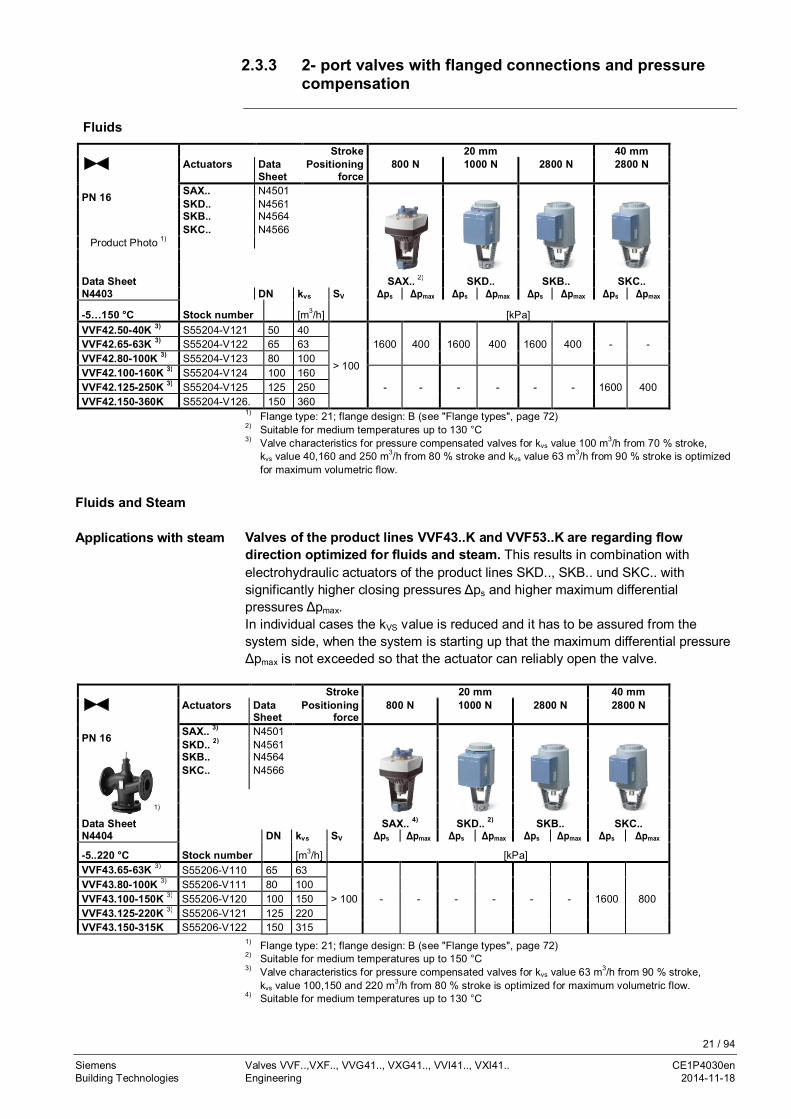
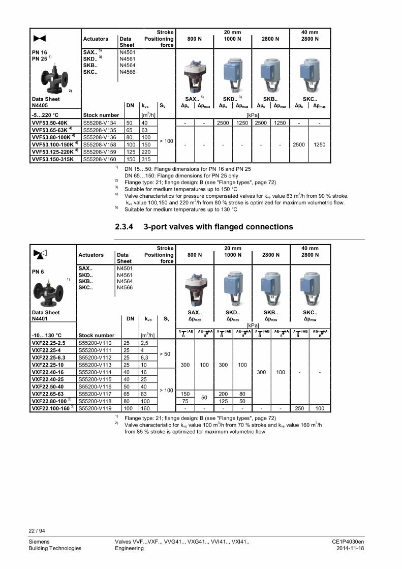
2.3.3 2- port valves with flanged connections and pressurecompensation
FluidsStroke 20 mm 40 mm
Actuators DataSheet
Positioningforce
800 N 1000 N 2800 N 2800 N
PN 16 SAX.. N4501SKD.. N4561
Product Photo 1)
SKB.. N4564SKC.. N4566
Data Sheet SAX.. 2) SKD.. SKB.. SKC..N4403 DN kvs SV Δps Δpmax Δps Δpmax Δps Δpmax Δps Δpmax
-5…150 °C Stock number [m3/h] [kPa]VVF42.50-40K 3) S55204-V121 50 40
> 100
1600 400 1600 400 1600 400 - -VVF42.65-63K 3) S55204-V122 65 63VVF42.80-100K 3) S55204-V123 80 100VVF42.100-160K 3) S55204-V124 100 160
- - - - - - 1600 400VVF42.125-250K 3) S55204-V125 125 250VVF42.150-360K S55204-V126. 150 360
1) Flange type: 21; flange design: B (see "Flange types", page 72)2) Suitable for medium temperatures up to 130 °C3) Valve characteristics for pressure compensated valves for kvs value 100 m3/h from 70 % stroke, kvs value 40,160 and 250 m3/h from 80 % stroke and kvs value 63 m3/h from 90 % stroke is optimized for maximum volumetric flow.
Valves of the product lines VVF43..K and VVF53..K are regarding flowdirection optimized for fluids and steam. This results in combination withelectrohydraulic actuators of the product lines SKD.., SKB.. und SKC.. withsignificantly higher closing pressures Δps and higher maximum differentialpressures Δpmax.In individual cases the kVS value is reduced and it has to be assured from thesystem side, when the system is starting up that the maximum differential pressureΔpmax is not exceeded so that the actuator can reliably open the valve.
Stroke 20 mm 40 mmActuators Data
SheetPositioning
force800 N 1000 N 2800 N 2800 N
PN 16 SAX.. 3) N4501SKD.. 2) N4561
1)
SKB.. N4564SKC.. N4566
Data Sheet SAX.. 4) SKD.. 2) SKB.. SKC..N4404 DN kvs SV Δps Δpmax Δps Δpmax Δps Δpmax Δps Δpmax
-5..220 °C Stock number [m3/h] [kPa]VVF43.65-63K 3) S55206-V110 65 63
> 100 - - - - - - 1600 800VVF43.80-100K 3) S55206-V111 80 100VVF43.100-150K 3) S55206-V120 100 150VVF43.125-220K 3) S55206-V121 125 220VVF43.150-315K S55206-V122 150 315
1) Flange type: 21; flange design: B (see "Flange types", page 72)2) Suitable for medium temperatures up to 150 °C3) Valve characteristics for pressure compensated valves for kvs value 63 m3/h from 90 % stroke, kvs value 100,150 and 220 m3/h from 80 % stroke is optimized for maximum volumetric flow.4) Suitable for medium temperatures up to 130 °C
Fluids and Steam
Applications with steam
22 / 94
Siemens Valves VVF..,VXF.., VVG41.., VXG41.., VVI41.., VXI41.. CE1P4030enBuilding Technologies Engineering 2014-11-18
Stroke 20 mm 40 mmActuators Data
SheetPositioning
force800 N 1000 N 2800 N 2800 N
PN 16PN 25 1)
SAX.. 5) N4501SKD.. 3) N4561
2)
SKB.. N4564SKC.. N4566
Data Sheet SAX.. 5) SKD.. 3) SKB.. SKC..N4405 DN kvs SV Δps Δpmax Δps Δpmax Δps Δpmax Δps Δpmax
-5…220 °C Stock number [m3/h] [kPa]VVF53.50-40K S55208-V134 50 40
> 100
- - 2500 1250 2500 1250 - -VVF53.65-63K 4) S55208-V135 65 63
- - - - - - 2500 1250VVF53.80-100K 4) S55208-V136 80 100VVF53.100-150K 4) S55208-V158 100 150VVF53.125-220K 4) S55208-V159 125 220VVF53.150-315K S55208-V160 150 315
1) DN 15…50: Flange dimensions for PN 16 and PN 25DN 65…150: Flange dimensions for PN 25 only
2) Flange type: 21; flange design: B (see "Flange types", page 72)3) Suitable for medium temperatures up to 150 °C4) Valve characteristics for pressure compensated valves for kvs value 63 m3/h from 90 % stroke,
kvs value 100,150 and 220 m3/h from 80 % stroke is optimized for maximum volumetric flow.5) Suitable for medium temperatures up to 130 °C
2.3.4 3-port valves with flanged connections
Stroke 20 mm 40 mmActuators Data
SheetPositioning
force800 N 1000 N 2800 N 2800 N
PN 6 SAX.. N4501SKD.. N4561
1) SKB.. N4564SKC.. N4566
Data Sheet SAX.. SKD.. SKB.. SKC..N4401 DN kvs SV Δpmax Δpmax Δpmax Δpmax
-10…130 °C Stock number [m3/h]
[kPa]
VXF22.25-2.5 S55200-V110 25 2,5
> 50
300 100 300 100300 100 - -
VXF22.25-4 S55200-V111 25 4VXF22.25-6.3 S55200-V112 25 6,3VXF22.25-10 S55200-V113 25 10VXF22.40-16 S55200-V114 40 16
> 100
VXF22.40-25 S55200-V115 40 25VXF22.50-40 S55200-V116 50 40VXF22.65-63 S55200-V117 65 63 150
50200 80
VXF22.80-100 2) S55200-V118 80 100 75 125 50VXF22.100-160 2) S55200-V119 100 160 - - - - - - 250 100
1) Flange type: 21; flange design: B (see "Flange types", page 72)2) Valve characteristic for kvs value 100 m3/h from 70 % stroke and kvs value 160 m3/h
from 85 % stroke is optimized for maximum volumetric flow

23 / 94
Siemens Valves VVF..,VXF.., VVG41.., VXG41.., VVI41.., VXI41.. CE1P4030enBuilding Technologies Engineering 2014-11-18
Stroke 20 mm 40 mmActuators Data
SheetPositioning
force800 N 1000 N 2800 N 2800 N
PN 10 SAX.. N4501SKD.. N4561
Productphoto
1) SKB.. N4564SKC.. N4566
Data Sheet SAX.. 2) SKD.. SKB.. SKC..N4402 DN kvs SV Δpmax Δpmax Δpmax Δpmax
-10…150 °C Stock number [m3/h]
[kPa]
VXF32.15-1.6 S55202-V113 15 1.6
>50400
100 400 100400 100 - -
VXF32.15-2.5 S55202-V114 15 2.5VXF32.15-4 S55202-V115 15 4VXF32.25-6.3 S55202-V116 25 6.3VXF32.25-10 S55202-V117 25 10VXF32.40-16 S55202-V118 40 16
>100
VXF32.40-25 S55202-V119 40 25VXF32.50-40 S55202-V120 50 40 300VXF32.65-63 S55202-V121 65 63 150
50200 80
VXF32.80-100 3) S55202-V122 80 100 75 125 50VXF32.100-160 3) S55202-V123 100 160
- - - - - -250
50VXF32.125-250 S55202-V124 125 250 160VXF32.150-400 3) S55202-V125 150 400 125
1) Flange type: 21; flange design: B (see "Flange types", page 72)2) Suitable for medium temperatures up to 130 °C3) Valve characteristic for kvs value 100 m3/h from 70 % stroke, kvs value 160 m3/h from 85 % stroke
and kvs value 400 m3/h from 90 % stroke is optimized for maximum volumetric flow

24 / 94
Siemens Valves VVF..,VXF.., VVG41.., VXG41.., VVI41.., VXI41.. CE1P4030enBuilding Technologies Engineering 2014-11-18
Stroke 20 mm 40 mmActuators Data
SheetPositioning
force800 N 1000 N 2800 N 2800 N
PN 16 SAX.. N4501SKD.. N4561
Productphoto
1) SKB.. N4564SKC.. N4566
Data Sheet SAX.. 2) SKD.. SKB.. SKC..N4403 DN kvs SV Δpmax Δpmax Δpmax Δpmax
-10…150 °C Stock number [m3/h]
[kPa]
VXF42.15-1.6 S55204-V127 15 1.6
> 50400
100 400 100
400 100 - -
VXF42.15-2.5 S55204-V128 15 2.5VXF42.15-4 S55204-V129 15 4VXF42.20-6.3 S55204-V130 20 6.3VXF42.25-6.3 S55204-V131 25 6.3VXF42.25-10 S55204-V132 25 10VXF42.32-16 S55204-V133 32 16
> 100
VXF42.40-16 S55204-V134 40 16VXF42.40-25 S55204-V135 40 25VXF42.50-31.5 S55204-V136 50 31.5
300VXF42.50-40 S55204-V137 50 40VXF42.65-50 S55204-V138 65 50
15050
200 80VXF42.65-63 S55204-V139 65 63VXF42.80-80 S55204-V140 80 80
75 125 50VXF42.80-100 3 S55204-V141 80 100VXF42.100-125 S55204-V142 100 125
- - - - - -
250 100VXF42.100-160 3 S55204-V143 100 160VXF42.125-200 S55204-V144 125 200
160VXF42.125-250 S55204-V145 125 25050VXF42.150-315 S55204-V146 150 315
125VXF42.150-400 3) S55204-V147 150 4001) Flange type: 21; flange design: B (see "Flange types", page 72)2) Suitable for medium temperatures up to 130 °C3) Valve characteristic for kvs value 100 m3/h from 70 % stroke, kvs value 160 m3/h from 85 % stroke
and kvs value 400 m3/h from 90 % stroke is optimized for maximum volumetric flow
25 / 94
Siemens Valves VVF..,VXF.., VVG41.., VXG41.., VVI41.., VXI41.. CE1P4030enBuilding Technologies Engineering 2014-11-18
Stroke 20 mm 40 mmActuators Data Sheet Positioning
force800 N 1000 N 2800 N 2800 N
PN 16 SAX.. 5) N4501SKD.. 2) N4561
1) SKB.. N4564SKC.. N4566
Data Sheet SAX.. 5) SKD.. 2) SKB.. SKC..N4404 DN kvs SV Δpmax Δpmax Δpmax Δpmax
-20…220 °C Stock number [m3/h]
[kPa]
VXF53.15-.. 3) S55208-.. 15 1.6/2.5/4
> 100
1200
200
1200
2001200
200 - -
VXF53.20-.. 3) S55208-.. 20 6.3VXF53.25-.. 3) S55208-.. 25 6.3/10VXF53.32-.. 3) S55208-.. 32 16 750 1100VXF53.40-.. 3) S55208-.. 40 16/25 500 650VXF53.50-.. 3) S55208-.. 50 40 300 400 1150
VXF43.65-63 4) S55206-V115 65 63
> 100 - - - - - -
650 200VXF43.80-100 4) S55206-V116 80 100 400 200VXF43.100-160 4) S55206-V117 100 160 250 150VXF43.125-250 4) S55206-V118 125 250 160 100VXF43.150-400 S55206-V119 150 400 100 70
1) Flange type: 21; flange design: B (see "Flange types", page 72)2) Suitable for medium temperatures up to 150 °C3) See VXF53.., PN 25 (data sheet N4405): Flange dimensions for PN 25 are the same as for PN 164) Valve is optimized for maximum volumetric flow:
- kvs value 63 m3/h from 90 % stroke,- kvs values 100, 160 and 250 m3/h from 80 % stroke
5) Suitable for medium temperatures up to 130 °C
Stroke 20 mm 40 mmActuators Data Sheet Positioning
force800 N 1000 N 2800 N 2800 N
PN 25PN 16 1)
SAX.. 5) N4501SKD.. 3) N4561
2) SKB.. N4564SKC.. N4566
Data Sheet SAX.. 5) SKD.. 3) SKB.. SKC..N4405 DN kvs SV Δpmax Δpmax Δpmax Δpmax
-20…220 °C Stock number [m3/h]
[kPa]
VXF53.15-1.6 S55208-V140 15 1.6
> 100
1200
200
1200
2001200
200 - -
VXF53.15-2.5 S55208-V141 15 2.5VXF53.15-4 S55208-V142 15 4VXF53.20-6.3 S55208-V144 20 6.3VXF53.25-6.3 S55208-V145 25 6.3VXF53.25-10 S55208-V146 25 10VXF53.32-16 4) S55208-V148 32 16 750 1100VXF53.40-16 S55208-V149 40 16
500 650VXF53.40-25 4) S55208-V150 40 25VXF53.50-40 4) S55208-V152 50 40 300 100 400 1150VXF53.65-63 4) S55208-V153 65 63
- - - - - -
650 200VXF53.80-100 4) S55208-V154 80 100 400 200VXF53.100-160 4) S55208-V155 100 160 250 150VXF53.125-250 4) S55208-V156 125 250 160 100VXF53.150-400 S55208-V157 150 400 100 70
1) DN 15…50: Flange dimensions for PN 16 and PN 25DN 65…150: Flange dimensions for PN 25 only
2) Flange type: 21; flange design: B (see "Flange types", page 72)3) Suitable for medium temperatures up to 150 °C4) Valve is optimized for maximum volumetric flow:
- kvs value 63 m3/h from 90 % stroke,- kvs values 16, 25, 40, 100, 160 and 250 m3/h from 80 % stroke
5) Suitable for medium temperatures up to 130 °C

26 / 94
Siemens Valves VVF..,VXF.., VVG41.., VXG41.., VVI41.., VXI41.. CE1P4030enBuilding Technologies Engineering 2014-11-18
2.3.5 3- port valves with threaded connections
Stroke 20 mmActuators Data Sheet Positioning
force800 N 1000 N 2800 N
PN 16 SAX.. 2) N4501SKD.. N4561SKB.. N4564
Data Sheet SAX.. 2) SKD.. SKB..N4463 Δpmax Δpmax Δpmax
-25…150 °C DN kvs SV
Threadedconnection
[kPa]
Typ Art.-Nr. Typ 1) Art.-Nr. 1) [m3/h] [Inch]- - VXG41.1301 VXG41.1301 15 1.6
>50
G 1B
800 200 800 200800
200
- - VXG41.1401 VXG41.1401 15 2.5 G 1BVXG41.15 VXG41.15 VXG41.1501 VXG41.1501 15 4 G 1BVXG41.20 VXG41.20 VXG41.2001 VXG41.2001 20 6.3
>100
G 1¼BVXG41.25 VXG41.25 VXG41.2501 VXG41.2501 25 10 G 1½BVXG41.32 VXG41.32 VXG41.3201 VXG41.3201 32 16 G 2BVXG41.40 VXG41.40 VXG41.4001 VXG41.4001 40 25 G 2¼B 525 150 775 150 150VXG41.50 VXG41.50 VXG41.5001 VXG41.5001 50 40 G 2¾B 300 100 450 100 200
1) These types, as a standard, are equipped with a tight bypass. DVGW and SVGW verified DVGWapplications according to drinking water regulation 2001. For medium temperatures up to 90 °C
2) Suitable for medium temperatures up to 130 °C
Stroke 20 mmActuators Data
SheetPositioning force 800 N 1000 N
PN 16 SAX.. N4501SKD.. N4561
Data Sheet SAX.. 1) SKD..N4362 DN kvs SV Threaded connection Δpmax Δpmax
-25…150 °C Artikelnummer [m3/h] [Inch]
[kPa]
VXI41.15-2.5 C/VXI41.15-2.5 15 2.5> 50
Rp ½
400100 400 100
VXI41.15-4 C/VXI41.15-4 15 4 Rp ½VXI41.20-6.3 C/VXI41.20-6.3 20 6.3
>100
Rp ¾VXI41.25-10 C/VXI41.25-10 25 10 Rp 1VXI41.32-16 C/VXI41.32-16 32 16 Rp 1¼VXI41.40-25 C/VXI41.40-25 40 25 Rp 1½VXI41.50-40 C/VXI41.50-40 50 40 Rp 2 300
1) Suitable for medium temperatures up to 130 °C
Valves of series VXI41... are only available in Asia.

27 / 94
Siemens Valves VVF..,VXF.., VVG41.., VXG41.., VVI41.., VXI41.. CE1P4030enBuilding Technologies Engineering 2014-11-18
2.3.6 Overview of actuators
Productnumber Stock number Stroke Positioning
forceOperatingvoltage
Positioningsignal
Springreturntime
Positioning time LED Manualadjuster
Auxiliaryfunctions
SAX31.00 S55150-A105
20 mm 800 N
AC 230 V 3-position
-
120 s-
Press and fix1)SAX31.03 S55150-A106
30 sSAX61.03 S55150-A100
AC 24 VDC 24 V
0…10 V4…20 mA0…1000 Ω
P2), 3)
SAX81.00 S55150-A1023-position -
120 s- Press and fix 1)
SAX81.03 S55150-A103 30 s
SKD32.21 SKD32.21
20 mm 1000 N
AC 230 V 3-position
8 s Opening: 30 sClosing: 10 s
-
Turn, positionis maintained
1)SKD32.50 SKD32.50 -
120 sSKD32.51 SKD32.51 8 sSKD60 SKD60
AC 24 V
0…10 V4…20 mA0…1000 Ω
-Opening: 30 sClosing: 15 s P
2)SKD62SKD62U
SKD62SKD62U 15 s
SKD62UA SKD62UA 4)
SKD82.50SKD82.50U
SKD82.50SKD82.50U
3-position-
120 s - 1)
SKD82.51SKD82.51U
SKD82.51SKD82.51U 8 s
SKB32.50 SKB32.50
20 mm 2800 N
AC 230 V 3-position-
120 s -
Turn, positionis maintained
1)
SKB32.51 SKB32.51 10 sSKB60 SKB60
AC 24 V
0…10 V4…20 mA0…1000 Ω
-Opening: 120 sClosing: 20 s P
2)SKB62SKB62U
SKB62SKB62U 10 s
SKB62UA SKB62UA 4)
SKB82.50SKB82.50U
SKB82.50SKB82.50U
3-position-
120 s - 1)
SKB82.51SKB82.51U
SKB82.51SKB82.51U 10 s
SKC32.60 SKC32.60
40 mm 2800 N
AC 230 V 3-position-
120 s -
Turn, positionis maintained
1)
SKC32.61 SKC32.61 18 sSKC60 SKC60
AC 24 V
0…10 V4…20 mA0…1000 Ω
-Opening: 120 sClosing: 20 s P
2)SKC62SKC62U
SKC62SKC62U 20 s
SKC62UA SKC62UA 4)
SKC82.60SKC82.60U
SKC82.60SKC82.60U
3-position-
120 s - 1)
SKC82.61SKC82.61U
SKC82.61SKC82.61U 18 s
1) Auxiliary switch, potentiometer2) Position feedback, forced control, selection of valve characteristic3) Optional: Sequence control, selection of acting direction4) Plus sequence control, stroke limitation, and selection of acting direction

28 / 94
Siemens Valves VVF..,VXF.., VVG41.., VXG41.., VVI41.., VXI41.. CE1P4030enBuilding Technologies Engineering 2014-11-18
2.4 Ordering
Product number Stock number Description QuantityVVF53.15-0.16 S55208-V100 2-port valve 1ASZ6.6 S55845-Z108 Stem heating element 1- 4 284 8806 0 Stem sealing gland EPDM 1
Actuator, valve and accessories are packed and supplied as separate items.
Counter-flanges, bolts and gaskets must be provided on site.
2.5 Accessories2.5.1 Electrical accessories
Product number Stock no. Description Note
ASZ6.6 S55845-Z108 Stem heating element Required for medium temperatures < 0 °C
When using a stem heating element and the medium temperature is below –5 °C,the stem sealing gland must be replaced. In that case, the sealing gland must beordered also (stock number 4 284 8806 0).
2.5.2 Mechanical accessories
Productnumber
Stocknumber
Mechanical stroke inverter
Description Valves DN SAX.. SKD.. SKB.. SKC.. SAV..
ASK50 ASK50
· Mechanical change ofacting direction for valveswith 20 mm stroke
· 0 % stroke of the actuatorcorresponds to 100 %stroke of the valve
· To be fitted betweenvalve and actuator
V..F22.. 25…80
- P - - -
V..F32.. 15…80
V..F42.. 15…80
V..F53.. 15…50
V..G41.. 15…50
V..I41.. 15…50
ASK51 ASK51
· Mechanical change ofacting direction for valveswith 20 mm stroke
· 0 % stroke of the actuatorcorresponds to 100 %stroke of the valve
· To be fitted betweenvalve and actuator
V..F22.. 25…80
- - P - -
V..F32.. 15…80
V..F42.. 15…80
V..F53.. 15…50
V..G41.. 15…50
Productnumber
Stocknumber Description Remark
- 428488060 Sealing gland
When using valves of the V..F43.. or V..F53.. lines with a stem heatingelement and a medium temperature of below -5 °C, the stem sealinggland must be replaced. With the gland 428488060 the valve can beused with water, water with antifreeze and brines between -20 °C and + 150 °C.
Example
Delivery
Note
NoteValve lines V..F43/53..

29 / 94
Siemens Valves VVF..,VXF.., VVG41.., VXG41.., VVI41.., VXI41.. CE1P4030enBuilding Technologies Engineering 2014-11-18
2.5.3 Adapters
Adapter type Stock number Bolts included Description VXF41.. Examples
ALF41B15 S55845-Z110 4x M12x90mm Adapter for replacing 3-portvalves VXF41.. by VXF43.. forDN ≥ 65 and VXF53.. for DN15…50.· Due to different dimensions
of the bypass flange· Every valve to be replaced
requires an adapter· Adapter is supplied with the
required number and size ofbolts and nuts as well as twosuitable flat sealings
DN 15 DN 15
DN 150ALF41B25 S55845-Z111 4x M12x90mm DN 25
ALF41B40 S55845-Z112 4x M16x90mm DN 40
ALF41B50 S55845-Z113 4x M16x90mm DN 50
ALF41B65 S55845-Z114 4x M16x90mm DN 65
ALF41B80 S55845-Z115 8x M16x110mm DN 80
ALF41B100 S55845-Z116 8x M16x110mm DN 100
ALF41B125 S55845-Z117 8x M16x110mm DN 125
ALF41B150 S55845-Z118 8x M20x110mm DN 150 DN 65
30 / 94
Siemens Valves VVF..,VXF.., VVG41.., VXG41.., VVI41.., VXI41.. CE1P4030enBuilding Technologies Engineering 2014-11-18
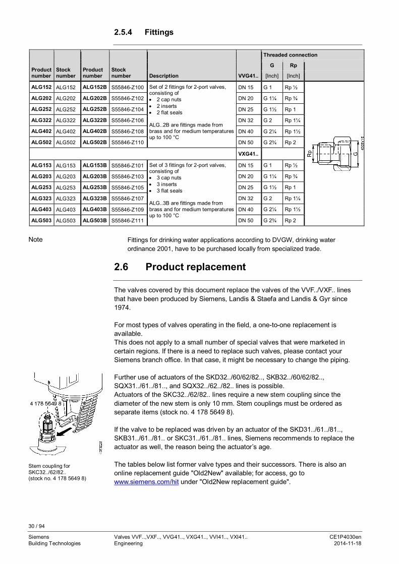
2.5.4 Fittings
Productnumber
Stocknumber
Productnumber
Stocknumber Description VVG41..
Threaded connection
G Rp
[Inch] [Inch]
ALG152 ALG152 ALG152B S55846-Z100 Set of 2 fittings for 2-port valves,consisting of· 2 cap nuts· 2 inserts· 2 flat seals
ALG..2B are fittings made frombrass and for medium temperaturesup to 100 °C
DN 15 G 1 Rp ½
ALG202 ALG202 ALG202B S55846-Z102 DN 20 G 1¼ Rp ¾
ALG252 ALG252 ALG252B S55846-Z104 DN 25 G 1½ Rp 1
ALG322 ALG322 ALG322B S55846-Z106 DN 32 G 2 Rp 1¼
ALG402 ALG402 ALG402B S55846-Z108 DN 40 G 2¼ Rp 1½
ALG502 ALG502 ALG502B S55846-Z110 DN 50 G 2¾ Rp 2
VXG41..
ALG153 ALG153 ALG153B S55846-Z101 Set of 3 fittings for 2-port valves,consisting of· 3 cap nuts· 3 inserts· 3 flat seals
ALG..3B are fittings made frombrass and for medium temperaturesup to 100 °C
DN 15 G 1 Rp ½
ALG203 ALG203 ALG203B S55846-Z103 DN 20 G 1¼ Rp ¾
ALG253 ALG253 ALG253B S55846-Z105 DN 25 G 1½ Rp 1
ALG323 ALG323 ALG323B S55846-Z107 DN 32 G 2 Rp 1¼
ALG403 ALG403 ALG403B S55846-Z109 DN 40 G 2¼ Rp 1½
ALG503 ALG503 ALG503B S55846-Z111 DN 50 G 2¾ Rp 2
Fittings for drinking water applications according to DVGW, drinking waterordinance 2001, have to be purchased locally from specialized trade.
2.6 Product replacement
The valves covered by this document replace the valves of the VVF../VXF.. linesthat have been produced by Siemens, Landis & Staefa and Landis & Gyr since1974.
For most types of valves operating in the field, a one-to-one replacement isavailable.This does not apply to a small number of special valves that were marketed incertain regions. If there is a need to replace such valves, please contact yourSiemens branch office. In that case, it might be necessary to change the piping.
Further use of actuators of the SKD32../60/62/82.., SKB32../60/62/82..,SQX31../61../81.., and SQX32../62../82.. lines is possible.Actuators of the SKC32../62/82.. lines require a new stem coupling since thediameter of the new stem is only 10 mm. Stem couplings must be ordered asseparate items (stock no. 4 178 5649 8).
If the valve to be replaced was driven by an actuator of the SKD31../61../81..,SKB31../61../81.. or SKC31../61../81.. lines, Siemens recommends to replace theactuator as well, the reason being the actuator’s age.
The tables below list former valve types and their successors. There is also anonline replacement guide "Old2New" available; for access, go towww.siemens.com/hit under "Old2New replacement guide".
Note
Stem coupling forSKC32../62/82..(stock no. 4 178 5649 8)

31 / 94
Siemens Valves VVF..,VXF.., VVG41.., VXG41.., VVI41.., VXI41.. CE1P4030enBuilding Technologies Engineering 2014-11-18
2.6.1 2-port valves
2-port valves with flanged connections Replacement
Type DN Adapter Stemcoupling 1)
Productnumber DN
VVF21.. - - - - - 25...80 - - VVF22.. 25...80VVF21.. - - - - - 100 - 4 178 5649 8 VVF22.. 100VVF31.. kVS- Werte 1.6, 2.5, 3, 4, 5, 6.3, 10, 12, 16, 19, 25, 40, 63, 100
15...80 - -VVF32..
15...80VVF31.. kVS- Werte 31, 49, 78 VVF42..VVF31.. kVS- Werte 160, 250
100...150 - 4 178 5649 8VVF32..
100...150VVF31.. kVS- Werte 125, 200, 300, 315 VVF42..VVF40.. - - - - - 15...80 - - VVF42.. 15...80VVF40.. - - - - - 100...150 - 4 178 5649 8 VVF42.. 100...150VVF41.49 VVF41.494
- -VVF41.495
-50 - - VVF53.50..2) 50
VVF41.50 VVF41.504 VVF41.505 50 - - VVF53.50.. 50VVF41.. VVF41..4 VVF41..5 65...150 - 4 178 5649 8 VVF43.. 65...150VVF45.49 VVF45.494
- - - -50 - 4 178 5649 8 - -
VVF45.50 VVF45.504 50 - 4 178 5649 8 VVF53.50 50VVF45.. VVF45..4 65...150 - 4 178 5649 8 VVF43.. 3) 65...150VVF52.. VVF52..A VVF52..G - VVF52..M - 15...40 - - VVF53.. 15...40
1) Since the new valves use uniform stem couplings, valves driven by electrohydraulic actuators SKC..require a new stem coupling
2) Replacement valves are the same nominal size DN, but have different kvs values. This must betaken into consideration when replacing a valve in the plant (stability, active stroke range)
3) If differential pressures are high, VVF43..K can be used as a replacement
When using valves of the V..F43.. or V..F53.. lines with a stem heating element anda medium temperature of below -5 °C, the stem sealing gland must be replaced. Inthat case, the sealing gland must be ordered also (stock number 4 284 8806 0).
Valves of the VVF45.. line close with the pressure, which means that when used incombination with SKB.. or SKC.. actuators, very high closing pressures arepermitted. If such closing pressures are indeed required, valves of the VVF43..Kline should be used as a replacement
The follow-on series VVF32 supports only select kVS values. For smaller kVS values,it makes more sense to replace the VVF31.. valve with series VVF42..valves. ThekVS values for services VVF42.. must support the kvs value for VVF31 valves.The valves series VVF31 and VVF42 are identical regarding face-to-facedimension, flange bolt circle and flange bolt dimensions.
Note
NoteValve line VVF45..
NoteValve line VVF31..from DN50
32 / 94
Siemens Valves VVF..,VXF.., VVG41.., VXG41.., VVI41.., VXI41.. CE1P4030enBuilding Technologies Engineering 2014-11-18
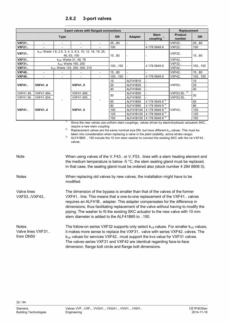
2.6.2 3-port valves
3-port valves with flanged connections Replacement
Type DN Adapter Stemcoupling 1)
Productnumber DN
VXF21.. - - - - 25...80 - - VXF22.. 25...80VXF21.. - - - - 100 4 178 5649 8 VXF22.. 100
VXF31.. kVS- Werte 1.6, 2.5, 3, 4, 5, 6.3, 10, 12, 16, 19, 25,40, 63, 100 15...80 - -
VXF32..15...80
VXF31.. kVS- Werte 31, 49, 78 VXF42..VXF31.. kVS- Werte 160, 250
100...150 - 4 178 5649 8VXF32..
100...150VXF31.. kVS- Werte 125, 200, 300, 315 VXF42..VXF40.. - - - - 15...80 - - VXF42.. 15...80VXF40.. - - - - 100...150 - 4 178 5649 8 VXF42.. 100...150
VXF41.. VXF41..4
-
VXF41..5
-
15 ALF41B15 -VXF53..
1525 ALF41B25 - 2540 ALF41B40 - 40
VXF41.49.. VXF41.494.. VXF41.495..50
ALF41B50 - VXF53.50.. 2)
50VXF41.50.. VXF41.504.. VXF41.505.. ALF41B50 - VXF53.50..
VXF41.. VXF41..4 VXF41..5
65 ALF41B65 4 178 5649 8 3)
VXF43..
6580 ALF41B80 4 178 5649 8 3) 80100 ALF41B100 4 178 5649 8 3) 100125 ALF41B125 4 178 5649 8 3) 125150 ALF41B150 4 178 5649 8 3) 150
1) Since the new valves use uniform stem couplings, valves driven by electrohydraulic actuators SKC..require a new stem coupling
2) Replacement valves are the same nominal size DN, but have different kvs values. This must betaken into consideration when replacing a valve in the plant (stability, active stroke range)
3) ALF41B65 .. 150 include the 10 mm stem washer to connect the existing SKC with the ne VXF43..valves.
When using valves of the V..F43.. or V..F53.. lines with a stem heating element andthe medium temperature is below -5 °C, the stem sealing gland must be replaced.In that case, the sealing gland must be ordered also (stock number 4 284 8806 0).
When replacing old valves by new valves, the installation might have to bemodified.
The dimension of the bypass is smaller than that of the valves of the formerVXF41.. line. This means that a one-to-one replacement of the VXF41.. valvesrequires an ALF41B.. adapter. This adapter compensates for the difference indimensions, thus facilitating replacement of the valve without having to modify thepiping. The washer to fit the existing SKC actuator to the new valve with 10 mmstem diameter is added to the ALF41B65 to ..150.
The follow-on series VXF32 supports only select kVS values. For smaller kVS values,it makes more sense to replace the VXF31.. valve with series VXF42..valves. ThekVS values for services VXF42.. must support the kvs value for VXF31 valves.The valves series VXF31 and VXF42 are identical regarding face-to-facedimension, flange bolt circle and flange bolt dimensions.
Note
Notes
Valve linesVXF53../VXF43..
NotesValve lines VXF31..from DN50

33 / 94
Siemens Valves VVF..,VXF.., VVG41.., VXG41.., VVI41.., VXI41.. CE1P4030enBuilding Technologies Engineering 2014-11-18
2.6.3 Accessories
Product number Stock number Description Note
ASZ6.5Not available fororder
ASZ6.5Not availablefor order
Stem heating element Required for medium temperatures< 0 °C
The ASZ6.5 stem heating element was compatible with actuators SKB.., SKC..,SKD.., and SQX... Always replace the installed steam heating element with theASZ6.6 (S55845-Z108) as needed. However, in the event the actuator needsreplacement as well when replacing the valve, ASZ6.5 stem heating elementsmust be replaced by ASZ6.6 on SAX series valves.
2.7 Spare parts
Productnumber DN Stock number Comments
2-port valves (Standard)
VVF22.. DN 25…100 4 284 8806 0 -
VVF32.. DN 15…150 4 284 8806 0 -
VVF42.. DN 15…150 4 284 8806 0 -
VVG41.. DN 15…50 4 284 8874 0 -
VVI41.. DN 15…50 4 284 8874 0 -
3-port valves (Standard)
VXF22.. DN 25…100 4 284 8806 0 -
VXF32.. DN 15…150 4 284 8806 0 -
VXF42.. DN 15…150 4 284 8806 0 -
VXG41.. DN 15…50 4 284 8874 0 -
VXG41..01 DN 15…50 74 284 0047 0 -
VXI41.. DN 15…50 4 284 8874 0 -
2-port valves (high-performance)
VVF53.. DN 15…15074 284 0061 0 -
4 284 8806 0 For medium temperatures below -5 °C
VVF43.. DN 65…15074 284 0061 0 -
4 284 8806 0 For medium temperatures below -5 °C
3-port valves (high-performance)
VXF53.. DN 15…15074 284 0061 0 -
4 284 8806 0 For medium temperatures below -5 °C
VXF43.. DN 65…15074 284 0061 0 -
4 284 8806 0 For medium temperatures below -5 °C
Note
Stem sealing gland

34 / 94
Siemens Valves VVF..,VXF.., VVG41.., VXG41.., VVI41.., VXI41.. CE1P4030enBuilding Technologies Engineering 2014-11-18
Productnumber DN Stock number
Stemdiameter Remarks
2-port valves (Standard)VVF21.. DN 25…80 4 284 8806 0 10 mm -
DN 100 4 679 5629 0 14 mmOnly for valves since productionyear 1980
VVF31.. DN 15…80 4 284 8806 0 10 mm -DN100…150 4 679 5629 0 14 mm Only for valves since production
year 1980VVF40.. DN 15…80 4 284 8806 0 10 mm -
DN100…150 4 679 5629 0 14 mm -
2-port valves (high-performance)VVF41..
DN 50…150
4 679 5629 0 14 mm Only for valves since productionyear 1982
VVF41..4 4 679 5630 0 14 mm · PTFE sleeve· For temperatures ≤ 180 °C
VVF41..54 284 9540 0 14 mm
· PTFE sleeve· Silicone-free version· For temperatures ≤ 180 °C
VVF45..DN 50…150
4 679 5629 0 14 mm -VVF45..4 4 679 5630 0 14 mm · PTFE sleeve
· For temperatures ≤ 180 °CVVF52..
DN 15…40
4 284 8806 0 10 mm -VVF52..AVVF52..G 4 284 8829 0 10 mm · PTFE sleeve
· For temperatures ≤ 180 °CVVF52..M
4 284 9538 0 10 mm· PTFE sleeve· Silicone-free version· For temperatures ≤ 180 °C
Productnumber DN Stock number
Stemdiameter Remarks
3-port valves (Standard)
VXF21.. DN 25…80 4 284 8806 0 10 mm -
DN 100 4 679 5629 0 14 mm Only for valves since productionyear 1980
VXF31.. DN 15…80 4 284 8806 0 10 mm -
DN 100…150 4 679 5629 0 14 mm Only for valves since productionyear 1980
VXF40.. DN 15…80 4 284 8806 0 10 mm -
DN 100…150 4 679 5629 0 14 mm -
3-port valves (high-performance)VXF41..
DN 15…40
4 284 8806 0 10 mm -
VXF41..4 4 284 8829 0 10 mm · PTFE sleeve· For temperatures ≤ 180 °C
VXF41..54 284 9538 0 10 mm
· PTFE sleeve· Silicone-free version· For temperatures ≤ 180 °C
VXF41..
DN 50…150
4 679 5629 0 14 mm Only for valves since productionyear 1980
VXF41..4 4 679 5630 0 14 mm · PTFE sleeve· For temperatures ≤ 180 °C
VXF41..54 284 9540 0 14 mm
· PTFE sleeve· Silicone-free version· For temperatures ≤ 180 °C
2-port valves VVF..Spare parts for expiredproduct lines
3-port valves VXF..Spare parts for expiredproduct lines
35 / 94
Siemens Valves VVF..,VXF.., VVG41.., VXG41.., VVI41.., VXI41.. CE1P4030enBuilding Technologies Engineering 2014-11-18
2.8 Valve sizing for fluids (water, heat transfer oil)
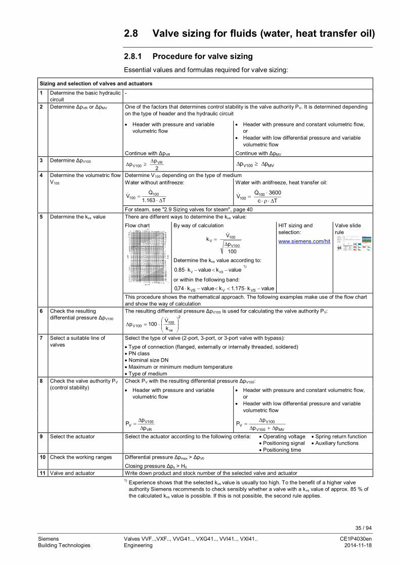
2.8.1 Procedure for valve sizingEssential values and formulas required for valve sizing:
Sizing and selection of valves and actuators
1 Determine the basic hydrauliccircuit
-
2 Determine ΔpVR or ΔpMV One of the factors that determines control stability is the valve authority PV. It is determined dependingon the type of header and the hydraulic circuit
· Header with pressure and variablevolumetric flow
· Header with pressure and constant volumetric flow,or
· Header with low differential pressure and variablevolumetric flow
Continue with ΔpVR Continue with ΔpMV
3 Determine ΔpV100
2pp VR
100VD
³D MV100V pp D³D
4 Determine the volumetric flowV100
Determine V100 depending on the type of mediumWater without antifreeze:
T163.1QV 100
100 D×=
&&
Water with antifreeze, heat transfer oil:
Tc3600Q
V 100100 D×r×
×=
&&
For steam, see "2.9 Sizing valves for steam", page 405 Determine the kvs value There are different ways to determine the kvs value:
Flow chart By way of calculation
100p
Vk
100V
100V
D=
&
Determine the kvs value according to:
valuekvaluek85.0 VSV -<-×1)
or within the following band:valuek175.1kvaluek74,0 VSVVS -×<<-×
HIT sizing andselection:
www.siemens.com/hit
Valve sliderule
This procedure shows the mathematical approach. The following examples make use of the flow chartand show the way of calculation
6 Check the resultingdifferential pressure ΔpV100
The resulting differential pressure ΔpV100 is used for calculating the valve authority PV:2
vs
100100V k
V100p ÷÷ø
öççè
æ×=D
&
7 Select a suitable line ofvalves
Select the type of valve (2-port, 3-port, or 3-port valve with bypass):
· Type of connection (flanged, externally or internally threaded, soldered)· PN class· Nominal size DN· Maximum or minimum medium temperature· Type of medium
8 Check the valve authority PV
(control stability)Check PV with the resulting differential pressure ΔpV100:
· Header with pressure and variablevolumetric flow
· Header with pressure and constant volumetric flow,or
· Header with low differential pressure and variablevolumetric flow
VR
100VV p
pP
DD
=MV100V
100VV pp
pP
D+DD
=
9 Select the actuator Select the actuator according to the following criteria: · Operating voltage· Positioning signal· Positioning time
· Spring return function· Auxiliary functions
10 Check the working ranges Differential pressure Δpmax > ΔpV0
Closing pressure Δps > H0
11 Valve and actuator Write down product and stock number of the selected valve and actuator1) Experience shows that the selected kvs value is usually too high. To the benefit of a higher valve
authority Siemens recommends to check sensibly whether a valve with a kvs value of approx. 85 % ofthe calculated kvs value is possible. If this is not possible, the second rule applies.

36 / 94
Siemens Valves VVF..,VXF.., VVG41.., VXG41.., VVI41.., VXI41.. CE1P4030enBuilding Technologies Engineering 2014-11-18
2.8.2 Flow chartKinematic viscosity υ < 10 mm2/s
2.8.3 Impact of fluid properties on valve sizing
Valves are sized based on the volumetric flow passing through them. The mostimportant characteristic of a valve is its kvs value. Since this value is determinedwith water at a temperature of 5…30 °C and a differential pressure Δp of 100 kPa(1 bar), additional influencing factors must be taken into consideration if theproperties of the medium passing through the valve are different.
Fluids
37 / 94
Siemens Valves VVF..,VXF.., VVG41.., VXG41.., VVI41.., VXI41.. CE1P4030enBuilding Technologies Engineering 2014-11-18
The following properties of a medium affect valve sizing:
· The density ρ and the specific heat capacity c have a direct impact on thevolumetric flow, which transfers the required amount of heat or cooling energy
· The kinematic viscosity ν influences the flow conditions (laminar or turbulent) inthe valve and thus the differential pressure Δp at a given volumetric flow V
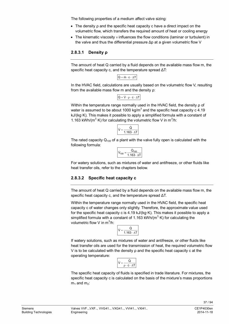
2.8.3.1 Density ρ
The amount of heat Q carried by a fluid depends on the available mass flow m, thespecific heat capacity c, and the temperature spread ΔT:
TcmQ D××= &&
In the HVAC field, calculations are usually based on the volumetric flow V, resultingfrom the available mass flow m and the density ρ:
TcVQ D××r×= &&
Within the temperature range normally used in the HVAC field, the density ρ ofwater is assumed to be about 1000 kg/m3 and the specific heat capacity c 4.19kJ/(kg·K). This makes it possible to apply a simplified formula with a constant of1.163 kWh/(m3·K) for calculating the volumetric flow V in m3/h:
T163.1QV
D×=
&&
The rated capacity Q100 of a plant with the valve fully open is calculated with thefollowing formula:
T163.1QV 100
100 D×=
&&
For watery solutions, such as mixtures of water and antifreeze, or other fluids likeheat transfer oils, refer to the chapters below.
2.8.3.2 Specific heat capacity c
The amount of heat Q carried by a fluid depends on the available mass flow m, thespecific heat capacity c, and the temperature spread ΔT.
Within the temperature range normally used in the HVAC field, the specific heatcapacity c of water changes only slightly. Therefore, the approximate value usedfor the specific heat capacity c is 4.19 kJ/(kg·K). This makes it possible to apply asimplified formula with a constant of 1.163 kWh/(m3·K) for calculating thevolumetric flow V in m3/h:
T163.1QV
D×=
&&
If watery solutions, such as mixtures of water and antifreeze, or other fluids likeheat transfer oils are used for the transmission of heat, the required volumetric flowV is to be calculated with the density ρ and the specific heat capacity c at theoperating temperature:
TcQV
D××r=
&&
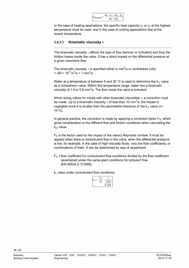
The specific heat capacity of fluids is specified in trade literature. For mixtures, thespecific heat capacity c is calculated on the basis of the mixture’s mass proportionsm1 and m2:
38 / 94
Siemens Valves VVF..,VXF.., VVG41.., VXG41.., VVI41.., VXI41.. CE1P4030enBuilding Technologies Engineering 2014-11-18
21
2211Gemisch mm
cmcmc+
×+×=
In the case of heating applications, the specific heat capacity c1 or c2 at the highesttemperature must be used, and in the case of cooling applications that at thelowest temperature.
2.8.3.3 Kinematic viscosity ν
The kinematic viscosity ν affects the type of flow (laminar or turbulent) and thus thefriction losses inside the valve. It has a direct impact on the differential pressure ata given volumetric flow.
The kinematic viscosity ν is specified either in mm2/s or centistokes (cSt):1 cSt = 10-6 m2/s = 1 mm2/s
Water at a temperature of between 5 and 30 °C is used to determine the kvs valueas a comparison value. Within this temperature range, water has a kinematicviscosity of 1.6 to 0.8 mm2/s. The flow inside the valve is turbulent.
When sizing valves for media with other kinematic viscosities ν, a correction mustbe made. Up to a kinematic viscosity ν of less than 10 mm2/s, the impact isnegligible since it is smaller than the permissible tolerance of the kvs value (+/-10 %).
In general practice, the correction is made by applying a correction factor FR, whichgives consideration to the different flow and friction conditions when calculating thekvs value.
FR is the factor used for the impact of the valve’s Reynolds number. It must beapplied when there is nonturbulent flow in the valve, when the differential pressureis low, for example, in the case of high-viscosity fluids, very low flow coefficients, orcombinations of them. It can be determined by way of experiment.
FR = flow coefficient for nonturbulent flow conditions divided by the flow coefficientascertained under the same plant conditions for turbulent flow(EN 60534-2-1[1998])
kv value under nonturbulent flow conditions
100p1
FVk
100
100
RV
D×=
&
39 / 94
Siemens Valves VVF..,VXF.., VVG41.., VXG41.., VVI41.., VXI41.. CE1P4030enBuilding Technologies Engineering 2014-11-18
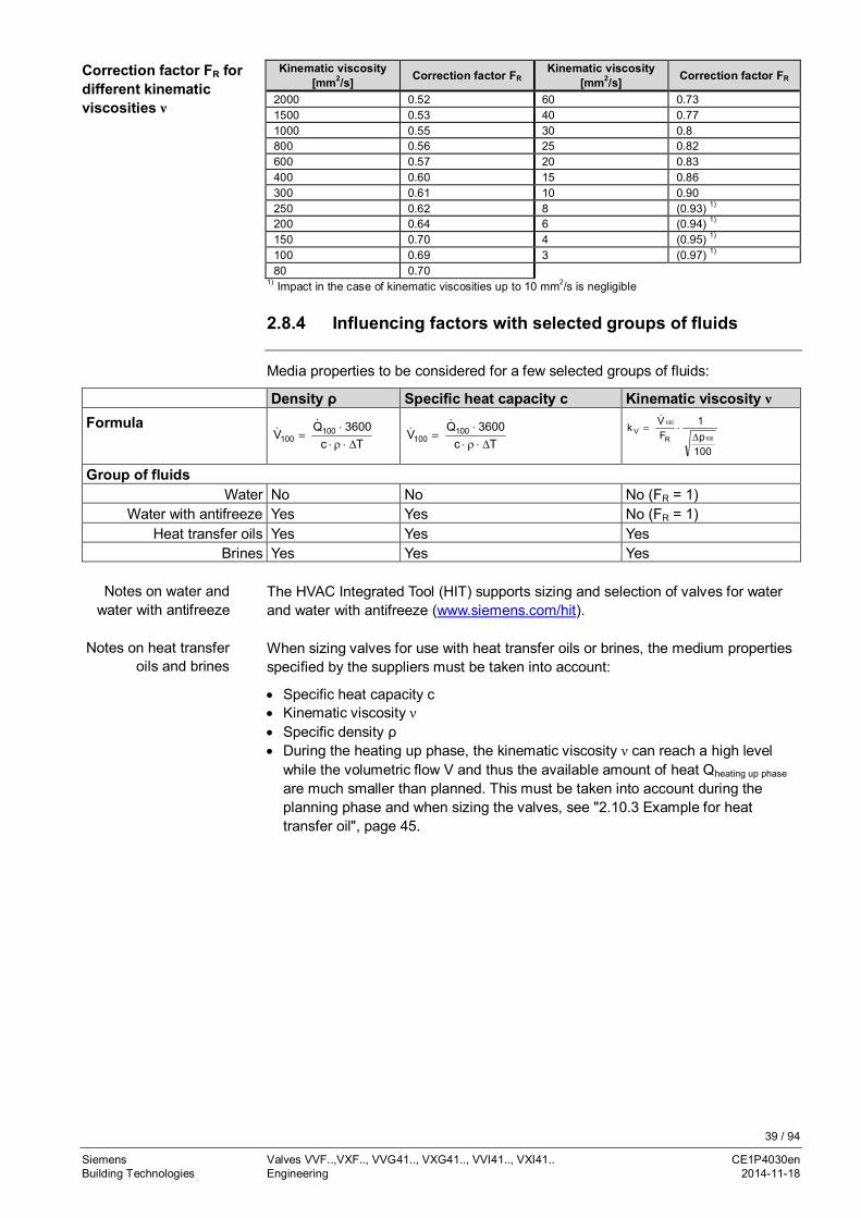
Kinematic viscosity[mm2/s] Correction factor FR
Kinematic viscosity[mm2/s] Correction factor FR
2000 0.52 60 0.731500 0.53 40 0.771000 0.55 30 0.8800 0.56 25 0.82600 0.57 20 0.83400 0.60 15 0.86300 0.61 10 0.90250 0.62 8 (0.93) 1)
200 0.64 6 (0.94) 1)
150 0.70 4 (0.95) 1)
100 0.69 3 (0.97) 1)
80 0.701) Impact in the case of kinematic viscosities up to 10 mm2/s is negligible
2.8.4 Influencing factors with selected groups of fluids
Media properties to be considered for a few selected groups of fluids:
Density ρ Specific heat capacity c Kinematic viscosity νFormula
Tc3600Q
V 100100 D×r×
×=
&&
Tc3600Q
V 100100 D×r×
×=
&&
100p1
FVk
100
100
RV
D×=
&
Group of fluidsWater No No No (FR = 1)
Water with antifreeze Yes Yes No (FR = 1)Heat transfer oils Yes Yes Yes
Brines Yes Yes Yes
The HVAC Integrated Tool (HIT) supports sizing and selection of valves for waterand water with antifreeze (www.siemens.com/hit).
When sizing valves for use with heat transfer oils or brines, the medium propertiesspecified by the suppliers must be taken into account:
· Specific heat capacity c· Kinematic viscosity ν· Specific density ρ· During the heating up phase, the kinematic viscosity ν can reach a high level
while the volumetric flow V and thus the available amount of heat Qheating up phase
are much smaller than planned. This must be taken into account during theplanning phase and when sizing the valves, see "2.10.3 Example for heattransfer oil", page 45.
Correction factor FR fordifferent kinematicviscosities ν
Notes on water andwater with antifreeze
Notes on heat transferoils and brines
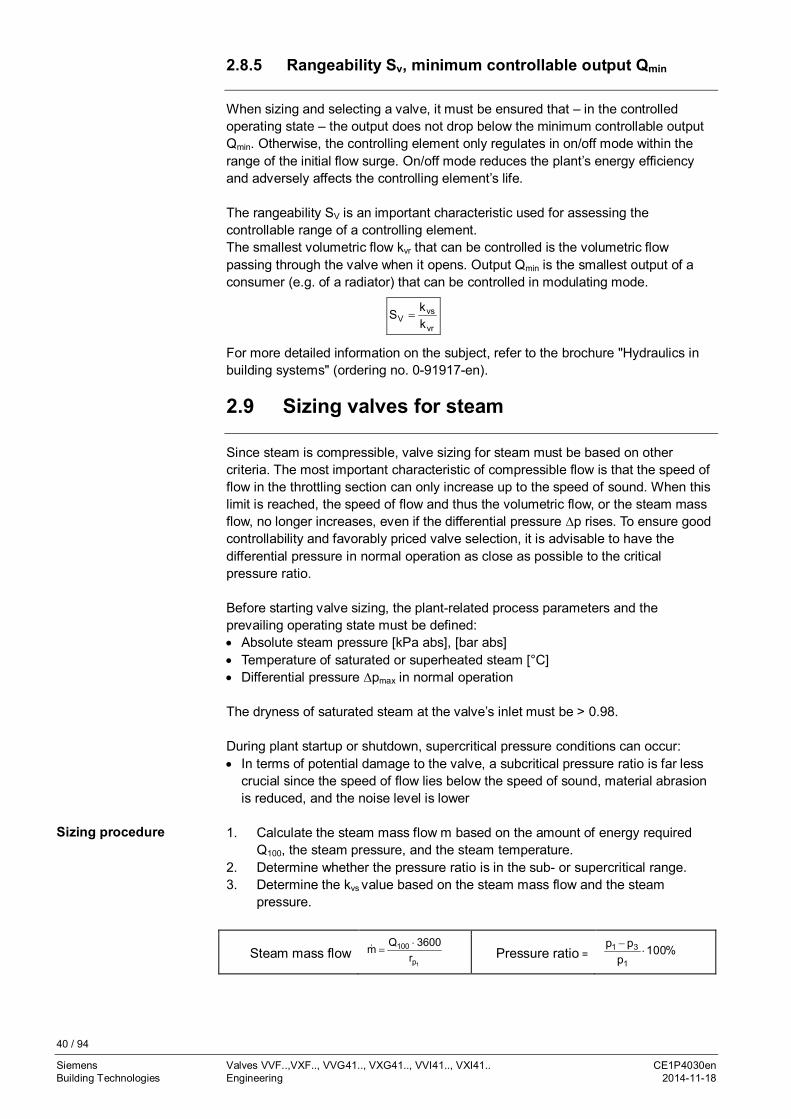
40 / 94
Siemens Valves VVF..,VXF.., VVG41.., VXG41.., VVI41.., VXI41.. CE1P4030enBuilding Technologies Engineering 2014-11-18
2.8.5 Rangeability Sv, minimum controllable output Qmin
When sizing and selecting a valve, it must be ensured that – in the controlledoperating state – the output does not drop below the minimum controllable outputQmin. Otherwise, the controlling element only regulates in on/off mode within therange of the initial flow surge. On/off mode reduces the plant’s energy efficiencyand adversely affects the controlling element’s life.
The rangeability SV is an important characteristic used for assessing thecontrollable range of a controlling element.The smallest volumetric flow kvr that can be controlled is the volumetric flowpassing through the valve when it opens. Output Qmin is the smallest output of aconsumer (e.g. of a radiator) that can be controlled in modulating mode.
vr
vsV k
kS =
For more detailed information on the subject, refer to the brochure "Hydraulics inbuilding systems" (ordering no. 0-91917-en).
2.9 Sizing valves for steam
Since steam is compressible, valve sizing for steam must be based on othercriteria. The most important characteristic of compressible flow is that the speed offlow in the throttling section can only increase up to the speed of sound. When thislimit is reached, the speed of flow and thus the volumetric flow, or the steam massflow, no longer increases, even if the differential pressure ∆p rises. To ensure goodcontrollability and favorably priced valve selection, it is advisable to have thedifferential pressure in normal operation as close as possible to the criticalpressure ratio.
Before starting valve sizing, the plant-related process parameters and theprevailing operating state must be defined:· Absolute steam pressure [kPa abs], [bar abs]· Temperature of saturated or superheated steam [°C]· Differential pressure ∆pmax in normal operation
The dryness of saturated steam at the valve’s inlet must be > 0.98.
During plant startup or shutdown, supercritical pressure conditions can occur:· In terms of potential damage to the valve, a subcritical pressure ratio is far less
crucial since the speed of flow lies below the speed of sound, material abrasionis reduced, and the noise level is lower
1. Calculate the steam mass flow m based on the amount of energy requiredQ100, the steam pressure, and the steam temperature.
2. Determine whether the pressure ratio is in the sub- or supercritical range.3. Determine the kvs value based on the steam mass flow and the steam
pressure.
Sizing procedure
Steam mass flow1p
100r
3600Qm ×=& Pressure ratio = %100
ppp
1
31 ×-

41 / 94
Siemens Valves VVF..,VXF.., VVG41.., VXG41.., VVI41.., VXI41.. CE1P4030enBuilding Technologies Engineering 2014-11-18
Subcritical range Supercritical range
%42%1001
31 <×-p
pp%42%100
1
31 ³×-p
pp
Pressure ratio < 42 % subcritical Pressure ratio ³ 42 % supercritical(not recommended)
k)pp(p
m4.4k313
vs ×-×
×=&
kpm8.8k
1vs ××=
&
Q100 = rated capacity in kWrp1 = specific heat capacity of steam in kJ/kgKp1 = absolute pressure at the valve inlet in kPa (prepressure)
p3 = absolute pressure at the valve outlet in kPa
m& = steam mass flow in kg/h
k = factor for superheating the steam = 1 + 0.0012 x DT (for saturated steam, k = 1)DT = temperature spread in K of saturated steam and superheated steam
The level of absolute pressure p1 at the valve inlet must be at least such that theabsolute pressure p3 at the valve outlet is higher than the atmospheric pressure.
When there is a pressure ratio (p1 – p3) / p1 >0.42, the flow passing through thenarrowest section of the valve reaches the speed of sound. This can lead to highernoise levels. A throttling system operating at a lower noise level (multistagepressure reduction, damping throttle by the outlet) alleviates the problem.
· Steam-controlled heat transfer medium without condensation· Shutoff valve on the steam side of condensation-controlled heat transfer media
· Steam humidifier· Steam-controlled heat transfer medium with condensation in the heat
exchanger
For saturated and superheated steam, the differential pressure Dpmax across thevalve should be as close as possible to the critical pressure ratio.
Abs
.ope
ratin
gpr
essu
re[b
ar] Chart example: The chart of the
selected valve must be observedX and Y: Suitable actuators,depending on the 2-port valve
Medium temperature [°C]
Water -
Wet steam To be avoidedSaturated steamSuperheated steam
Permissible operatingrange
Calculation of kvsvalue for steam
Note
Notes on thesupercritical range
Subcritical < 42 %
Supercritical ≥ 42 %
Recommendation fordifferential pressureDpmax

42 / 94
Siemens Valves VVF..,VXF.., VVG41.., VXG41.., VVI41.., VXI41.. CE1P4030enBuilding Technologies Engineering 2014-11-18
Water vapor table for the saturated state (pressure table)
Pressure Temperature Spec. volumewater
Spec. volumesteam
Density steam Enthalpy water Enthalpysteam
Heat ofvaporization
p p T V' V'' ρ'' h' h'' r[kPa] [bar] [°C] [dm3/kg] [m3/kg] [kg/m3] [kJ/kg] [kJ/kg] [kJ/kg]
12
3
4
0.0100.020
0.030
0.040
6.980817.513
24.100
28.983
1.00011.0012
1.0027
1.0040
129.2067.01
45.67
34.80
0.0077390.01492
0.02190
0.02873
29.3473.46
101.00
121.41
2514.12533.6
2545.6
2554.5
2485.02460.2
2444.6
2433.1
5
6
78
9
0.050
0.060
0.0700.080
0.090
32.898
36.183
39.02541.534
43.787
1.0052
1.0064
1.00741.0084
1.0094
28.19
23.74
20.5318.10
16.20
0.03547
0.04212
0.048710.05523
0.06171
137.77
151.50
163.38173.86
183.28
2561.6
2567.5
2572.62577.1
2581.1
2423.8
2416.0
2409.22403.2
2397.9
10
2030
40
50
0.10
0.200.30
0.40
0.50
45.833
60.08669.124
75.886
81.345
1.0102
1.01721.0223
1.0265
1.0301
14.67
7.6505.229
3.993
3.240
0.06814
0.13070.1912
0.2504
0.3086
191.83
251.45289.30
317.65
340.56
2584.8
2609.92625.4
2636.9
2646.0
2392.9
2358.42336.1
2319.2
2305.4
60
70
8090
100
0.60
0.70
0.800.90
1.0
85.954
89.959
93.51296.713
99.632
1.0333
1.0361
1.03871.0412
1.0434
2.732
2.365
2.0871.869
1.694
0.3661
0.4229
0.47920.5350
0.5904
359.93
376.77
391.72405.21
417.51
2653.6
2660.1
2665.82670.9
2675.4
2293.6
2283.3
2274.02265.6
2257.9
150
200250
300
350
1.5
2.02.5
3.0
3.5
111.37
120.23127.43
133.54
138.87
1.0530
1.06081.0675
1.0735
1.0789
1.159
0.88540.7184
0.6056
0.5240
0.8628
1.1291.392
1.651
1.908
467.13
504.70535.34
561.43
584.27
2693.4
2706.32716.4
2724.7
2731.6
2226.2
2201.62181.0
2163.2
2147.4
400
450
500600
700
4.0
4.5
5.06.0
7.0
143.62
147.92
151.84158.84
164.96
1.0839
1.0885
1.09281.1009
1.1082
0.4622
0.4138
0.37470.3155
0.2727
2.163
2.417
2.6693.170
3.667
604.67
623.16
640.12670.42
697.06
2737.6
2742.9
2747.52755.5
2762.0
2133.0
2119.7
2107.42085.0
2064.9
800900
1'000
1'1001'200
1'300
1'400
8.09.0
10
1112
13
14
170.41175.36
179.88
184.07187.96
191.61
195.04
1.11501.1213
1.1274
1.13311.1386
1.1438
1.1489
0.24030.2148
0.1943
0.17740.1632
0.1511
0.1407
4.1624.655
5.147
5.6376.127
6.617
7.106
720.94742.64
762.61
781.13798.43
814.70
830.08
2767.52772.1
2776.2
2779.72782.7
2785.4
2787.8
2046.52029.5
2013.6
1998.51984.3
1970.7
1957.7
1'5001'600
1'700
1'8001'900
1516
17
1819
198.29201.37
204.31
207.11209.80
1.15391.1586
1.1633
1.16781.1723
0.13170.1237
0.1166
0.11030.1047
7.5968.085
8.575
9.0659.555
844.67858.56
871.84
884.58896.81
2798.92791.7
2793.4
2794.82796.1
1945.21933.2
1921.5
1910.31899.3
2'000
2'5003'000
4'000
5'000
20
2530
40
50
212.37
223.94233.84
250.33
263.91
1.1766
1.19721.2163
1.2521
1.2858
0.09954
0.079910.06663
0.04975
0.03743
10.05
12.5115.01
10.10
25.36
908.59
961.961008.4
1087.4
1154.5
2797.2
2800.92802.3
2800.3
2794.2
1888.6
1839.01793.9
1712.9
1639.7
6'000
7'000
8'0009'000
60
70
8090
275.55
285.79
294.97303.31
1.3187
1.3513
1.38421.4179
0.03244
0.02737
0.023530.02050
30.83
36.53
42.5148.79
1213.7
1267.4
1317.11363.7
2785.0
2773.5
2759.92744.6
1571.3
1506.0
1442.81380.9
10'000
11'000
12'00013'000
14'000
100
110
120130
140
310.96
318.05
324.65330.83
336.64
1.4526
1.4887
1.52681.5672
1.6106
0.01804
0.01601
0.014280.01280
0.01150
55.43
62.48
70.0178.14
86.99
1408.0
1450.6
1491.81532.0
1571.6
2727.7
2729.3
2689.22667.0
2642.4
1319.7
1258.7
1197.41135.0
1070.7
15'00020'000
22'000
22'120
150200
220
221.2
342.13365.70
373.69
374.15
1.65792.0370
2.6714
3.17
0.010340.005877
0.003728
0.00317
96.71170.2
268.3
315.5
1611.01826.5
2011.1
2107.4
2615.02418.4
2195.6
2107.4
1004.0591.9
184.5
0
Water vapor table
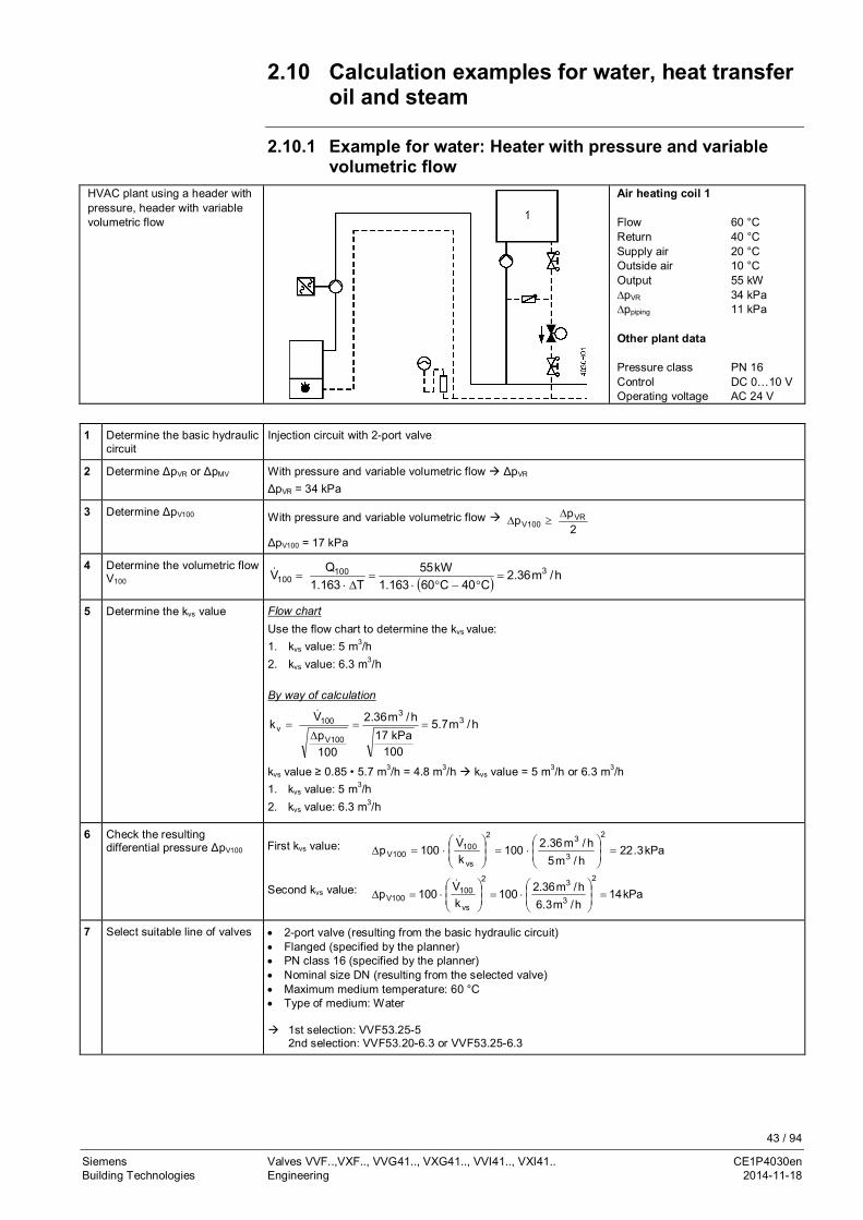
43 / 94
Siemens Valves VVF..,VXF.., VVG41.., VXG41.., VVI41.., VXI41.. CE1P4030enBuilding Technologies Engineering 2014-11-18
2.10 Calculation examples for water, heat transferoil and steam
2.10.1 Example for water: Heater with pressure and variablevolumetric flow
HVAC plant using a header withpressure, header with variablevolumetric flow
Air heating coil 1
Flow 60 °CReturn 40 °CSupply air 20 °COutside air 10 °COutput 55 kW∆pVR 34 kPa∆ppiping 11 kPa
Other plant data
Pressure class PN 16Control DC 0…10 VOperating voltage AC 24 V
1 Determine the basic hydrauliccircuit
Injection circuit with 2-port valve
2 Determine ΔpVR or ΔpMV With pressure and variable volumetric flow à ΔpVR
ΔpVR = 34 kPa
3 Determine ΔpV100 With pressure and variable volumetric flow à2pp VR
100VD
³D
ΔpV100 = 17 kPa
4 Determine the volumetric flowV100 ( ) h/m36.2
C40C60163.1kW55
T163.1QV 3100
100 =°-°×
=D×
=&
5 Determine the kvs value Flow chartUse the flow chart to determine the kvs value:1. kvs value: 5 m3/h2. kvs value: 6.3 m3/h
By way of calculation
h/m7.5
100kPa17
h/m36.2
100p
Vk 33
100V
100v ==
D=
&
kvs value ≥ 0.85 • 5.7 m3/h = 4.8 m3/h à kvs value = 5 m3/h or 6.3 m3/h1. kvs value: 5 m3/h2. kvs value: 6.3 m3/h
6 Check the resultingdifferential pressure ΔpV100 First kvs value: kPa3.22
h/m5h/m36.2100
kV100p
2
3
32
vs
100100V =÷
÷ø
öççè
æ×=÷
÷ø
öççè
æ×=D
&
Second kvs value: kPa14h/m3.6h/m36.2100
kV100p
2
3
32
vs
100100V =÷
÷ø
öççè
æ×=÷
÷ø
öççè
æ×=D
&
7 Select suitable line of valves · 2-port valve (resulting from the basic hydraulic circuit)· Flanged (specified by the planner)· PN class 16 (specified by the planner)· Nominal size DN (resulting from the selected valve)· Maximum medium temperature: 60 °C· Type of medium: Water
à 1st selection: VVF53.25-5 2nd selection: VVF53.20-6.3 or VVF53.25-6.3

44 / 94
Siemens Valves VVF..,VXF.., VVG41.., VXG41.., VVI41.., VXI41.. CE1P4030enBuilding Technologies Engineering 2014-11-18
8 Check the valve authority PV
(control stability)Check PV using the resulting differential pressure ΔpV100:
First kvs value: 66.0kPa34kPa3.22
pp
PVR
100VV ==
DD
=
Second kvs value: 41.0kPa34kPa14
pp
PVR
100VV ==
DD
=
à Higher valve authority PV à kvs value = 5 m3/h
9 Select the actuator Select actuator according to the following criteria:· Operating voltage· Positioning signal· Positioning time· Spring return function· Auxiliary functions
10 Check the working ranges Differential pressure Δpmax > ΔpV0
Closing pressure Δps > H0
11 Select valve and actuator Type of valve: VVF53.25-5
Type of actuator: According to the table
2.10.2 Example for water: Heater with low differential pressurewithout main pump
HVAC plant using a header withlow differential pressure withoutmain pump
Heating group 1
Flow 60 °CReturn 45 °COutput 70 kW∆pheat meter 8 kPa∆ppiping 3 kPa
Other plant data
Pressure class PN 16Control 3-positionOperating voltage AC 230 V
1 Heating group 12 Boiler 1
1 Determine the basic hydrauliccircuit
Mixing circuit
2 Determine ΔpVR or ΔpMV Header with low differential pressure and variable volumetric flow à ΔpMV
ΔpMV = Δppiping + Δpheat meter = 3 kPa + 8 kPa = 11 kPa
3 Determine ΔpV100 Header with low differential pressure and variable volumetric flow à ΔpV100 ≥ ΔpMV
ΔpV100 = 11 kPa
4 Determine the volumetric flowV100 ( ) h/m4
C45C60163.1kW70
T163.1QV 3100
100 =°-°×
=D×
=&
5 Determine the kvs value Flow chartUse the flow chart to determine the kvs value:kvs value: 12 m3/h
By way of calculation
h/m1.12
100kPa11
h/m4
100p
Vk 33
100V
100v ==
D=
&
kvs value ≥ 0.85 • 12 m3/h = 10.2 m3/h à kvs value = 10 m3/hkvs value: 10 m3/h

45 / 94
Siemens Valves VVF..,VXF.., VVG41.., VXG41.., VVI41.., VXI41.. CE1P4030enBuilding Technologies Engineering 2014-11-18
6 Check the resultingdifferential pressure ΔpV100 kPa16
h/m10h/m4100
kV100p
2
3
32
vs
100100V =÷
÷ø
öççè
æ×=÷
÷ø
öççè
æ×=D
&
7 Select suitable line of valves · 2-port valve (resulting from the basic hydraulic circuit)· Flanged (specified by the planner)· PN class 16 (specified by the planner)· Nominal size DN (resulting from selected valve)· Maximum medium temperature: 60 °C· Type of medium: Water
à Selection: VXF53.25-10
8 Check the valve authority PV(control stability)
Check PV using the resulting differential pressure ΔpV100:
59.0kPa11kPa16
kPa16pp
pPMV100V
100VV =
+=
D+DD
=
9 Select the actuator Select actuator according to the following criteria:· Operating voltage· Positioning signal· Positioning time· Spring return function· Auxiliary functions
10 Check the working ranges Differential pressure Δpmax > ΔpV0
Closing pressure Δps > H0
11 Select valve and actuator Type of valve: VXF53.25-10
Type of actuator: According to the table
2.10.3 Example for heat transfer oil
As outlined in chapter "2.8.3 Impact of fluid properties on valve sizing", page 36,when sizing a valve, the density ρ, the specific heat capacity c, and the kinematicviscosity ν must be taken into consideration. Also, to ensure correct and efficientoperation, a closer look should be taken at the controlled mode and the startupmode.
Properties
Description Mobiltherm 603
Max. permissible flow temperature 285 °C
Max. permissible film temperature 315 °C
Kinematic viscosity at 20 °C 50.5 mm2/s
Kinematic viscosity at 100/200/300 °C 4.2/1.2/0.58 mm2/s
Density at 20 °C 859 kg/m3
Density at 100/200/300 °C 811/750/690 kg/m3
Specific heat capacity c at 20 °C 1.89 kJ/kgK
Specific heat capacity c at 100/200/300 °C 2.18/2.54/2.91 kJ/kgK
When planning and commissioning a plant or when sizing valves, the suppliers’specifications must be observed. The experience and know-how of the suppliershelp select the right type of heat transfer oil.
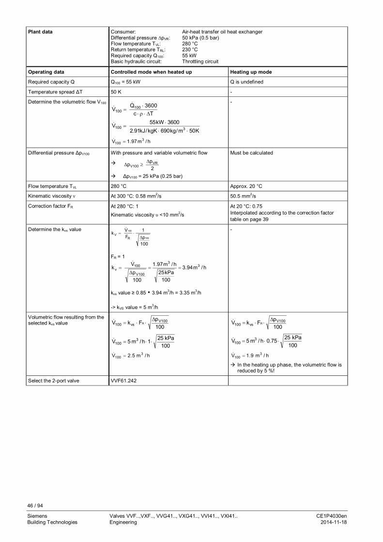
46 / 94
Siemens Valves VVF..,VXF.., VVG41.., VXG41.., VVI41.., VXI41.. CE1P4030enBuilding Technologies Engineering 2014-11-18
Plant data Consumer: Air-heat transfer oil heat exchangerDifferential pressure ∆pVR: 50 kPa (0.5 bar)Flow temperature TVL: 280 °CReturn temperature TRL: 230 °CRequired capacity Q100: 55 kWBasic hydraulic circuit: Throttling circuit
Operating data Controlled mode when heated up Heating up mode
Required capacity Q Q100 = 55 kW Q is undefined
Temperature spread ΔT 50 K -
Determine the volumetric flow V100
Tc3600Q
V 100100 D×r×
×=
&&
K50m/kg690kgK/kJ91.23600kW55V
3100××
×=&
h/m97.1V 3100 =&
-
Differential pressure ΔpV100 With pressure and variable volumetric flow
à2pp VR
100VD
³D
à ΔpV100 = 25 kPa (0.25 bar)
Must be calculated
Flow temperature TVL 280 °C Approx. 20 °C
Kinematic viscosity ν At 300 °C: 0.58 mm2/s 50.5 mm2/s
Correction factor FR At 280 °C: 1
Kinematic viscosity υ <10 mm2/s
At 20 °C: 0.75Interpolated according to the correction factortable on page 39
Determine the kvs value
100p1
FVk
100
100
RV
D×=
&
FR = 1
h/m94.3
100kPa25
h/m97.1
100p
Vk 33
100V
100v ==
D=
&
kvs value ≥ 0.85 • 3.94 m3/h = 3.35 m3/h
-> kVS value = 5 m3/h
-
Volumetric flow resulting from theselected kvs value
100pFkV 100V
vs100 RD
××=&
100kPa251h/m5V 3
100 ××=&
h/m5.2V 3100 =&
100pFkV 100V
vs100 RD
××=&
100kPa2575.0h/m5V 3
100 ××=&
h/m9.1V 3100 =&
à In the heating up phase, the volumetric flow isreduced by 5 %!
Select the 2-port valve VVF61.242

47 / 94
Siemens Valves VVF..,VXF.., VVG41.., VXG41.., VVI41.., VXI41.. CE1P4030enBuilding Technologies Engineering 2014-11-18
2.10.4 Example for steam
As outlined in chapter "2.9 Sizing valves for steam", page 40, it must bedetermined first whether a supercritical or subcritical pressure ratio exists in theplant.
Saturated steam = 151.8 °CPrepressure p1 = 500 kPa (5 bar)Steam mass flow m& = 460 kg/h
Given Pressure ratio = 30 % Pressure ratio ≥ 42 %(supercritical permitted)
Subcritical pressure ratio Supercritical pressure ratio
Required kvs, valve type kvs, valve type
Solution%100p%30pp 1
13×
-=
)bar5.3(kPa350%100
kPa500%30kPa500p3 =×
-=
1)kPa350kPa500(kPa350
h/kg4604.4kv ×-×
×=
kv = 8.83 m3/h
1kPa500
h/kg4608.8k v ××=
kv = 8.09 m3/h
Selected kvs = 10 m3/h à VVF53.25-10 kvs = 8 m3/h à VVF53.25-8
Given Saturated steam = 133.5 °CPrepressure p1 = 150 kPa (1.5 bar)Steam mass flow m& = 75 kg/hDifferential pressure = 40 kPa (0.4 bar)
Required kvs, valve type
Solution 1. Vertical line upward to an absolute prepressure p1 = 1.5 bar (150 kPa).2. Horizontal line to the right to the point of intersection 1.5 bar (15 kPa) and differential
pressure 0.4 bar (40 kPa).3. Vertical line downward to 75 kg/h.4. Point of intersection kvs value
Select available kvs value of VVF.. valve lines.5. Selected kvs value: 5 m3/h.
Selected kvs value: 5 m3/h à VVF53.25-5
Given Superheated steam = 251.8 °CSaturated steam = 151.8 °CSuperheating TD = 100 KPrepressure p1 = 500 kPa (5 bar)Steam mass flow m& = 150 kg/hDifferential pressure = 200 kPa (2 bar)
Required kvs, valve type
Solution 1. Vertical line upward to an absolute prepressure p1 = 5 bar (500 kPa).2. Horizontal line to the right to the point of intersection 5 bar (500 kPa) and differential
pressure 2 bar (200 kPa).3. Scale "Superheated steam": Along the line at 150 kg/h upward to superheating at
100 K, then the vertical line upward.4. Point of intersection kvs value
Select available kvs value of VVF.. valve lines.5. Selected kvs value: 3.15 m3/h.
Selected kvs value: 3.15 m3/h à VVF53.15-3.2
Example 1:By way of calculation
Example 2:With chart
Example 3:With chart

48 / 94
Siemens Valves VVF..,VXF.., VVG41.., VXG41.., VVI41.., VXI41.. CE1P4030enBuilding Technologies Engineering 2014-11-18
Example 3:Superheatedsteam
Example 2:Saturatedsteam

49 / 94
Siemens Valves VVF..,VXF.., VVG41.., VXG41.., VVI41.., VXI41.. CE1P4030enBuilding Technologies Engineering 2014-11-18
2.11 Valve characteristics2.11.1 2-port valves
Flow
rate
k v/k
vs 0…30 %: Linear30…100 %: Equal-percentage
ngl = 3 as per VDI / VDE 2173For certain valve lines and high kvs values,the valve characteristic is optimized formaximum volumetric flow kV100.
Stroke H / H100
Flow
rate
k v/k
vs
0…100 %: Linear
Stroke H / H100
2.11.2 3-port valves
Flow
rate
k v/k
vs
Throughport A-AB0...30 %: Linear30...100 %: Equal-percentage
ngl = 3 as per VDI / VDE 2173For certain valve lines and high kvs values,the valve characteristic is optimized formaximum volumetric flow kv100.Bypass B-AB0...100 %: LinearPort AB = constant flowPort A = variable flowPort B = bypass (variable flow)
Stroke H / H100
Mixing: Flow from port A and port B to port ABDiverting: Flow from port AB to port A and port AB
Stroke H / H100
For valves:VVF32.125-250VVF42.125-250VVF42.125-250KVVF43.125-200VVF43.125-250VVF43.125-220KVVF53.125-250VVF53.125-220KVVF32.150-400VVF42.150-400VVF42.150-360KVVF43.150-400VVF43.150-315KVVF53.150-400VVF53.150-315K
Flow
rate
k v/k
vs
Throughport A-AB0...100 %: LinearBypass B-AB0...100 %: Linear
For valves:VXF32.125-250VXF42.125-250VXF43.125-250VXF53.125-250VXF32.150-400VXF42.150-400VXF43.150-400VXF53.150-400
50 / 94
Siemens Valves VVF..,VXF.., VVG41.., VXG41.., VVI41.., VXI41.. CE1P4030enBuilding Technologies Engineering 2014-11-18
2.12 Operating pressure and medium temperature2.12.1 ISO 7005 and EN 1092 – a comparison
ISO 7005 and EN 1092 cover PN-classified, round flanges for pipes, valves, plainfittings and accessories, plus their dimensions and tolerances, categorizedaccording to different types of materials.Both standards also contain the assignment of pressures and mediumtemperatures.The connecting dimensions, flange and face types plus descriptions conform to therelevant ISO 7005 standards.
· ISO 7005, part 1: Steel flanges· ISO 7005, part 2: Cast iron flanges· ISO 7005, part 3: Flanges made of copper alloys
Since the valves covered by this document are used throughout the world, theinternational standard ISO 7005 was selected as a basis. The information givenbelow explains the differences between ISO 7005 and EN 1092.
The international standard ISO 7005-1 on steel flanges was used as a basis for thedevelopment of EN 1092. EN 1092 deviates from ISO 7005 in the following ways:· It solely covers flanges with PN designation· A number of technical requirements of flanges originating from DIN standards
have been changed
The differences between EN 1092-1 and ISO 7005-1 are as follows:· In many cases, the pressure-temperature assignments of this standard have
been reduced, either by limiting the assignments at lower temperatures – whichmay no longer exceed the value of the PN class – or by increasing the rate atwhich the admissible pressure drops on temperature rise
· In addition to the PN 2.5 – PN 40 range of flanges originating from DINstandards, which is defined in ISO 7005, EN 1092 also contains flanges up toPN 400
In terms of flanges of the same PN class, this standard refers to ISO 7005-2 andISO 2531. Flange types and connecting dimensions are compatible with the sameDN and PN class of ISO 7005 and ISO 2531.· Pressure-temperature assignments: There are no differences between EN 1092-
2 and ISO 7005-2
In terms of flanges of the same PN class, this standard refers to ISO 7005-3.Flange types and connecting dimensions are compatible with the same DN and PNclass of ISO 7005.· Pressure-temperature assignments: There are no differences between EN 1092-
3 and ISO 7005-3
To be able to make use of the permissible operating pressures and operatingtemperatures according to EN 1092-1 as listed in the following tables/graphs, high-quality steel is required when using steel flanges.Otherwise, the permissible plant operating pressures must be reduced as specifiedin EN 1092-1.
EN 1092: Part 1,steel flanges
EN 1092: Part 2,cast iron flanges
EN 1092: Part 3, flangesmade of copper alloys
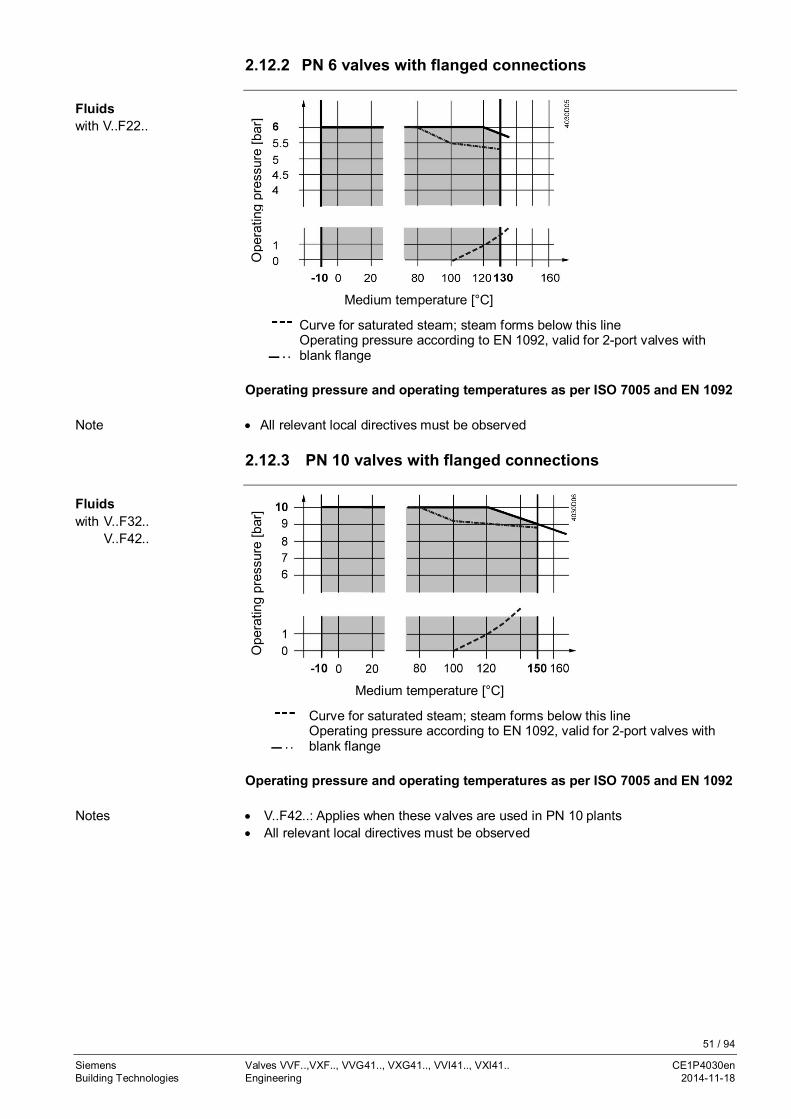
51 / 94
Siemens Valves VVF..,VXF.., VVG41.., VXG41.., VVI41.., VXI41.. CE1P4030enBuilding Technologies Engineering 2014-11-18
2.12.2 PN 6 valves with flanged connections
Ope
ratin
gpr
essu
re[b
ar]
Medium temperature [°C]
Curve for saturated steam; steam forms below this lineOperating pressure according to EN 1092, valid for 2-port valves withblank flange
Operating pressure and operating temperatures as per ISO 7005 and EN 1092
· All relevant local directives must be observed
2.12.3 PN 10 valves with flanged connections
Ope
ratin
gpr
essu
re[b
ar]
Medium temperature [°C]
Curve for saturated steam; steam forms below this lineOperating pressure according to EN 1092, valid for 2-port valves withblank flange
Operating pressure and operating temperatures as per ISO 7005 and EN 1092
· V..F42..: Applies when these valves are used in PN 10 plants· All relevant local directives must be observed
Fluidswith V..F22..
Note
Fluidswith V..F32..
V..F42..
Notes
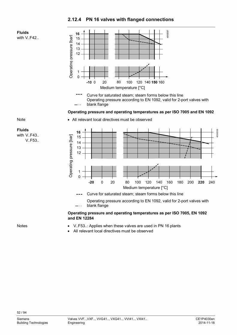
52 / 94
Siemens Valves VVF..,VXF.., VVG41.., VXG41.., VVI41.., VXI41.. CE1P4030enBuilding Technologies Engineering 2014-11-18
2.12.4 PN 16 valves with flanged connections
Ope
ratin
gpr
essu
re[b
ar]
Medium temperature [°C]
Curve for saturated steam; steam forms below this lineOperating pressure according to EN 1092, valid for 2-port valves withblank flange
Operating pressure and operating temperatures as per ISO 7005 and EN 1092
· All relevant local directives must be observed
Operating pressure and operating temperatures as per ISO 7005, EN 1092and EN 12284
· V..F53..: Applies when these valves are used in PN 16 plants· All relevant local directives must be observed
Fluidswith V..F42..
Note
Fluidswith V..F43..
V..F53..
Ope
ratin
gpr
essu
re[b
ar]
Medium temperature [°C]Curve for saturated steam; steam forms below this line
Operating pressure according to EN 1092, valid for 2-port valves withblank flange
Notes
120 160140
1213
16
01008020
1415
1
180 200 220 240-20 0

53 / 94
Siemens Valves VVF..,VXF.., VVG41.., VXG41.., VVI41.., VXI41.. CE1P4030enBuilding Technologies Engineering 2014-11-18
Abs
.ope
ratin
gpr
essu
re[b
ar]
Medium temperature [°C]
1 Water -
2 Wet steam To be avoided
3 Saturated steamSuperheated steam Permissible operating range
A Subcritical pressure ratioB Supercritical pressure ratio
2.12.5 PN 25 valves with flanged connections
Ope
ratin
gpr
essu
re[b
ar]
Medium temperature [°C]
Curve for saturated steam; steam forms below this lineOperating pressure according to EN 1092, valid for 2-port valves withblank flange
Operating pressure and operating temperatures as per ISO 7005, EN 1092and EN 12284
· All relevant local directives must be observed
-20
2524232221201918
10
-10 1800 20 80 100 200120 140 160 220 240
Saturated steamSuperheated steamwith VVF43..
VVF43..K
FluidsV..F53..
Note
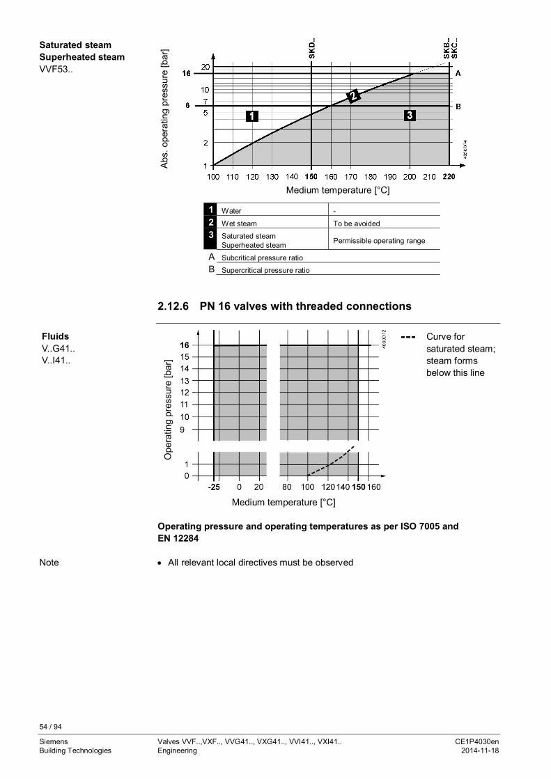
54 / 94
Siemens Valves VVF..,VXF.., VVG41.., VXG41.., VVI41.., VXI41.. CE1P4030enBuilding Technologies Engineering 2014-11-18
Abs
.ope
ratin
gpr
essu
re[b
ar]
Medium temperature [°C]
1 Water -2 Wet steam To be avoided3 Saturated steam
Superheated steam Permissible operating range
A Subcritical pressure ratioB Supercritical pressure ratio
2.12.6 PN 16 valves with threaded connections
Ope
ratin
gpr
essu
re[b
ar]
Curve forsaturated steam;steam formsbelow this line
Medium temperature [°C]
Operating pressure and operating temperatures as per ISO 7005 andEN 12284
· All relevant local directives must be observed
Saturated steamSuperheated steamVVF53..
FluidsV..G41..V..I41..
Note

55 / 94
Siemens Valves VVF..,VXF.., VVG41.., VXG41.., VVI41.., VXI41.. CE1P4030enBuilding Technologies Engineering 2014-11-18
Abs
.ope
ratin
gpr
essu
re[b
ar]
Medium temperature [°C]
1 Water -2 Wet steam To be avoided3 Saturated steam
Superheated steam Permissible operating range
Abs
.ope
ratin
gpr
essu
re[b
ar]
Medium temperature [°C]
1 Water -
2 Wet steam To be avoided
3 Saturated steamSuperheated steam Permissible operating range
3
1 2
3
1 2SK
D..
SAX.
.
Saturated steamSuperheated steamVVG41..
VVI41..

56 / 94
Siemens Valves VVF..,VXF.., VVG41.., VXG41.., VVI41.., VXI41.. CE1P4030enBuilding Technologies Engineering 2014-11-18
2.13 Cavitation
Due to high speeds of the medium inthe narrowest section of the valve, localunderpressure occurs (p2). If thispressure drops below the medium’sboiling pressure, cavitation occurs(steam bubbles), possibly leading tomaterial removal (abrasion). Also, whencavitation sets in, the noise levelincreases abruptly. Cavitation can beavoided by limiting the pressuredifferential across the valve as afunction of the medium temperature andthe prepressure.
Progression of speed Progression of pressure p
Dpmax = differential pressure with valve almost fully closed atwhich cavitation can largely be avoided
p1 = static pressure at valve inletp3 = static pressure at valve outletM = pumpJ = water temperature
Pressure p1 at valve inlet: 500 kPa (5 bar)Water temperature: 120 °C
From the chart above it can be seen that with the valve almost fully closed, themaximum permissible differential pressure Dpmax is 200 kPa (2 bar).
Example for low-temperature hot water

57 / 94
Siemens Valves VVF..,VXF.., VVG41.., VXG41.., VVI41.., VXI41.. CE1P4030enBuilding Technologies Engineering 2014-11-18
Spring water cooling as an example for avoiding cavitation:
Cold water = 12 °Cp1 = 500 kPa (5 bar)p4 = 100 kPa (1 bar)
(atmospheric pressure)Dpmax = 300 kPa (3 bar)
Dp3-3’ = 20 kPa (0.2 bar)DpD (throttle) = 80 kPa (0.8 bar)p3’ = pressure downstream
from the consumer inkPa
To avoid cavitation in the case of cold water circuits, it must also be made certainthat there is sufficient static counter-pressure at the valve’s outlet. This can beensured by installing a throttling valve downstream from the heat exchanger, forexample. In that case, the maximum pressure drop across the valve should beselected according to the 80 °C curve in the flow chart above on page 56.
2.14 Medium quality and medium treatment
All relevant local directives must be observed whenever it comes to water quality,corrosion or contamination.
2.14.1 Water
· Water treatment as per VDI 2035 to avoid boiler scale and damage due tocorrosion on the water side
· The requirements of DIN EN 12953-10 should be observed· Local guidelines and directives should be observed
Install a strainer (dirt trap).
· The company making the installation is responsible for the water quality in HVACplants
· Before filling a hydraulic HVAC circuit with water, the installer must observe thespecifications of suppliers regarding water quality. If such specifications orregulations are not observed, severe damage to the plant can occur
· When commissioning a plant, the company that made the installation is obligedto write a commissioning report including information about water quality andfilling (plant volume) and, if necessary, about water treatment and the additivesused
Keep a plant record.
The installer should check hydraulic HVAC circuits at least once a year.
Before adding water to a hydraulic HVAC circuit, the installer must observe thespecifications of suppliers regarding water quality (water treatment as per VDI2035). If such specifications or regulations are not observed, severe damage to theplant can occur.
When adding water at a later stage, the company that made the installation isobliged to write a commissioning report including information about water qualityand the filling (plant volume) and, if necessary, about water treatment and theadditives used.
Example for coldwater
Note
Note
Planning
Installation andcommissioning
Recommendation
Maintenance andservice

58 / 94
Siemens Valves VVF..,VXF.., VVG41.., VXG41.., VVI41.., VXI41.. CE1P4030enBuilding Technologies Engineering 2014-11-18
To prevent boiler scale and damage resulting from corrosion, the water quality inopen or closed plants must be checked at regular intervals. The plant record mustalways be kept up to date.
2.14.2 Water with antifreeze
For water with antifreeze, such as ethylene glycol or propylene glycol, the supplier-specific values for the density ρ, the specific heat capacity c, and the kinematicviscosity ν are to be determined by way of concentration and medium temperature.These values must be observed when sizing valves to make certain that correct kvs
values are obtained.
In the case of antifreeze concentrations with a kinematic viscosity of < 10 mm2/s,correction factors for the sizing of valves are not required. Refer to chapter "2.8.3Impact of fluid properties on valve sizing", page 36.
· The type of antifreeze (product and dosage) added to the system must beapproved by the supplier for use in HVAC plants
· If several additives are used (e.g. antifreeze and hardness stabilizers), therequired combination must be approved by the same supplier
· Install a strainer (dirt trap)
· The company making the installation is responsible for the correct antifreezeconcentration and water quality in HVAC plants
· Before filling a hydraulic HVAC circuit with a medium, the installer must observethe specifications of the supplier. If such specifications or regulations are notobserved, severe damage to the plant can occur
· When commissioning a plant, the company that made the installation is obligedto write a commissioning report including information about water quality,antifreeze concentration and filling (plant volume) and, if necessary, about watertreatment and the additives used
Keep a plant record.
The installer should check hydraulic HVAC circuits at least once a year.According to supplier specifications, the antifreeze concentration, the pH value,and the concentration of inhibitors must be checked once a year, for example.
The antifreeze concentration and water quality in open or closed HVAC plants mustbe checked at regular intervals. The plant record must always be kept up to date.
Recommendation
Note
Planning
Installation andcommissioning
Recommendation
Maintenance andservice
Recommendation
59 / 94
Siemens Valves VVF..,VXF.., VVG41.., VXG41.., VVI41.., VXI41.. CE1P4030enBuilding Technologies Engineering 2014-11-18
2.14.3 Deionized, demineralized water and super-clean water
These media have an impact on valve selection (material of O-rings, gaskets,plug/seat, and valve body). Compatibility must be checked.
Deionized water Demineralized water Super-clean water
The ions of saltscontained in the waterhave been removed
The minerals contained inthe water have beenremoved
Intensely treated water with a high specificresistance and containing no organicsubstances
To avoid corrosion and to ensure a long service life of the valves, gaskets andplugs, the following limits must be observed:· Oxygen: < 0.02 mg/l· pH value: 8.2…8.5· Electric conductance: < 5 mSi· Sum of alkaline earths: < 0.0051 mmol/l· Hardness: < 0.03 °dH
· The media must be approved by the supplier for use in HVAC plants· Install a strainer (dirt trap)
· The company making the installation is responsible for the quality of the mediaused
· Before filling a hydraulic HVAC circuit with a medium, the installer must observethe supplier’s specification. If such specifications or regulations are notobserved, severe damage to the plant can occur
· When commissioning a plant, the company that made the installation is obligedto write a commissioning report including information about medium quality andfilling (plant volume) and, if necessary, about water treatment and additives used
Keep a plant record.
The installer should check hydraulic HVAC circuits at least once a year.
The quality of the medium used in open or closed HVAC plants must be checked atregular intervals. The plant record must always be kept up to date.
Note
Planning
Installation andcommissioning
Recommendation
Maintenance, service
Recommendation

60 / 94
Siemens Valves VVF..,VXF.., VVG41.., VXG41.., VVI41.., VXI41.. CE1P4030enBuilding Technologies Engineering 2014-11-18
2.14.4 Heat transfer oil (thermal oil)
Heat transfer oil has an impact on valve selection (material of O-rings andgaskets). Compatibility must be checked.
When planning and commissioning a plant or when sizing valves, the suppliers’specifications must be observed. To make certain the right type of heat transfer oilis used, one should rely on the suppliers’ experience and know-how.
When using heat transfer oil (thermal oil), the following supplier-specific valuesmust be taken into consideration:· Correction factor FR, if the supplier-specific kinematic viscosity ν exceeds
10 mm2/s· Density ρ· Room and operating temperature· During the heating up phase, the kinematic viscosity ν is very high. The
volumetric flow is much smaller than planned and thus the available amount ofenergy Qheating up phase as well. This must be taken into account during theplanning phase and when sizing the valve
Refer to chapter "2.8.3 Impact of fluid properties on valve sizing", page 36.
· Heat transfer media on the basis of mineral oil· Synthetic heat transfer fluids· Organic heat transfer fluids as per DIN 4754· Heat transfer media of a uniform substance or mixture· Heat transfer oils on the basis of silicon
Install a strainer (dirt trap).
· The company making the installation is responsible for the quality of the mediaused
· Before filling a hydraulic HVAC circuit with a medium, the installer must observethe supplier’s specification. If such specifications or regulations are notobserved, severe damage to the plant can occur
· When commissioning a plant, the company that made the installation is obligedto write a commissioning report including information about medium quality andfilling (plant volume) and, if necessary, about water treatment and the additivesused
Keep a plant record.
The installer should check hydraulic HVAC circuits at least once a year.
Before adding medium to a hydraulic HVAC circuit, the installer must observe thesupplier’s specification. If such specifications or regulations are not observed,severe damage to the plant can occur.When adding medium at a later stage, the company that made the installation isobliged to write a commissioning report including information about the quality ofthe medium and the filling (plant volume) and, if necessary, about treatment andadditives used.
The quality of the medium in open or closed plants must be checked at regularintervals. The plant record must always be kept up to date.
Note
Types of heattransfer oil
Planning
Installation andcommissioning
Recommendation
Maintenance andservice
Recommendation

61 / 94
Siemens Valves VVF..,VXF.., VVG41.., VXG41.., VVI41.., VXI41.. CE1P4030enBuilding Technologies Engineering 2014-11-18
2.15 Engineering notes2.15.1 Strainer (dirt trap)
Open and closed HVAC plants require a strainer (dirt trap). This improves thequality of the water, ensures proper functioning of the valve, and a long service lifeof the HVAC plant with its components.
2.15.2 Avoiding flow noise
To reduce flow noise, abruptreductions in pipe diameters, tightpipe bends, sharp edges orreductions in the vicinity of valvesshould be avoided. A settling pathshould be provided.Recommendation:· L ≥ 10 x DN, at least 0,4 mAlso, the flow must be free fromcavitation (refer to page 54).
2.15.3 Avoiding false circulation
When 3-port valves in HVAC plants are fully closed, false circulation can occurwhen hot water rises or when water is pulled away near rectangular pipeconnections.
False circulation can be avoided by proper planning – with almost no extra cost –but remedy is usually very costly in existing plants.
· Observe guide value for the water speed: 0.5…1 m/s.The lower the water speed, the smaller the risk that the diverted flow pulls waterfrom the critical piping section. If required, balancing valves can be installed toimprove flow conditions
· Observe a certain distance between bypass and collector/header or short-circuit:H ≥ 10 x pipe dia., minimum 400 mm
or· Installation of a check valve or gravity brake R with small spring pressure in the
critical piping section, aimed at ensuring a minimum flow in the opening range
Note
Measures againstfalse circulation

62 / 94
Siemens Valves VVF..,VXF.., VVG41.., VXG41.., VVI41.., VXI41.. CE1P4030enBuilding Technologies Engineering 2014-11-18
· Welded elbows.
2.15.4 Thermal insulation
Insulated pipes and valves saveenergy.
Actuators must never be insulated.This is to make certain that heatproduced by the actuator can bedissipated, thus preventingoverheating.
Recommendation:Thermal insulation of pipes andvalves conforming to EnEV 2009
# Type of pipes/valves Minimum thickness ofthermal insulation
1 Inside diameter up to 22 mm 20 mm2 Inside diameter 22…35 mm 30 mm3 Inside diameter 35…100 mm Same as inside diameter4 Inside diameter > 100 mm 100 mm5 Through walls and ceilings, at pipe crossings
and connections, at central network distributors½ of requirements of# 1…4
Recommendation 1)

63 / 94
Siemens Valves VVF..,VXF.., VVG41.., VXG41.., VVI41.., VXI41.. CE1P4030enBuilding Technologies Engineering 2014-11-18
6 Pipes of central heating systems which, afterJanuary 31, 2002, were installed betweenheated rooms of different users
½ of requirements of# 1…4
7 Pipes according to # 6 in the floor’s structure 6 mm8 Cooling energy distribution/cold water pipes
and valves of room ventilation and airconditioning systems
6 mm
1) Applies to a heat conductance of 0.035 W/(m·K)
When using materials with a heat conductance other than 0.035 W/(m·K), theminimum thickness of the insulating layers must be appropriately adapted. For theconversion and heat conductance of insulating material, the calculation methodsand data applied by established technical rules must be used.
2.16 Warranty
The engineering data listed in chapter "Type summary and equipmentcombinations" on page 14 are ensured only when the valves are used inconnection with the specified Siemens actuators.
If the valves are used in combination with actuators supplied by thirds, properfunctioning must be ensured by the user himself and Siemens BuildingTechnologies will assume no liability.
Note

64 / 94
Siemens Valves VVF..,VXF.., VVG41.., VXG41.., VVI41.., VXI41.. CE1P4030enBuilding Technologies Handling 2014-11-18
3 Handling3.1 Mounting and installation
The valves must be installed free from distortion:
3.1.1 Mounting positions
Indoors Outdoors 1)
1) Only in combination with weather shield ASK39.1 and actuators SAX..
Mounting positions apply to both 2- and 3-port valves.
3.1.2 Direction of flow for fluids and steam
For general illustration and further details, refer to chapter "4.3 Technical andmechanical design", page 70.
Fluids Steam
VVF22.., VVF32..,VVF42.., VVK42..K,VVG41.., VVI41..
VVG41..VVI41..
Closing against the pressure Closing against the pressure Closing with the pressure
For use with all actuators For use with all actuators
Note
2-port valves

65 / 94
Siemens Valves VVF..,VXF.., VVG41.., VXG41.., VVI41.., VXI41.. CE1P4030enBuilding Technologies Handling 2014-11-18
Fluids Steam
VVF43…VVF53..
VVF43.., VVF43..KVVF53.., VVF53..K
VVF43.., VVF43..K,VVF53.., VVF53..K
Closing against the pressure Closing with the pressure Closing with the pressure
For use with all actuators Use with electro-hydraulicactuators only
Use with electro-hydraulicactuators only
2-port valves do not become 3-port valves by removing the blank flange!
Fluids
Mixing valve (preferred use) Diverting valve
3.1.3 Flanges
To ensure that flanges are correctly connected, the nominal, maximum andminimum tightening torques must be observed. They depend on the strength andsize of the bolts and nuts, the material of the flanges, the PN class, the flangegaskets used and the medium in the hydraulic system.
The tightening torques also depend on the specification of the gasket supplier andmust be observed, using a torque wrench.
To determine the right tightening torques, refer to the suppliers’ specifications.According to EN 1515-1, the selection of materials for bolts and nuts is alsodependent on the PN class, the temperatures, and other operating conditions, suchas the type of medium.
Hinweis
3-port valves

66 / 94
Siemens Valves VVF..,VXF.., VVG41.., VXG41.., VVI41.., VXI41.. CE1P4030enBuilding Technologies Handling 2014-11-18
Use a torque wrench.
1. Clean the flanges.2. Place the gaskets between the flanges.3. Fit the bolts, washers and nuts and tighten
them by hand.4. Tighten the bolts crosswise in 3 steps as
shown below (M = tightening torque):· Step 1: 25 % M· Step 2: 50 % M· Step 3: 100 % M
1 to 8 = order for tightening the boltsM = tightening torque
Notes: • Too low or too high tightening torques can cause leakage at theflange connections or even lead to broken flanges
• Observe the following table "Guide values for tightening torques",page 66
5. When the operating temperature is reached, retighten the bolts.
DN 15 20 25 32 40 50 65 80 100 125 150Max. tightening torque [Nm]PN 6 - - 40 - 40 40 40 40 120- - -PN 10 40 - 40 - 120 120 120 120 120 120 120PN 16 40 40 40 120 120 120 120 120 120 120 200PN 25 40 40 40 120 120 120 120 120 200 300 300PN 40 40 40 40 120 120 120 120 120 200 300 300
Recommendation
Procedure
Guide values fortightening torques
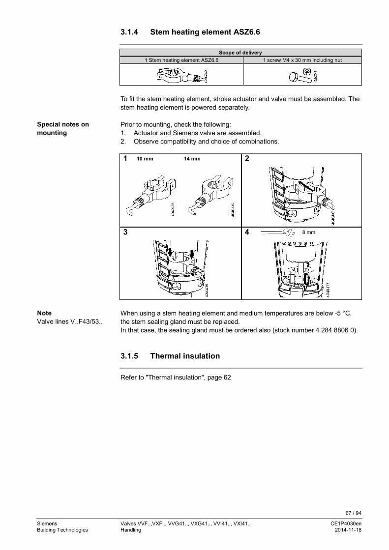
67 / 94
Siemens Valves VVF..,VXF.., VVG41.., VXG41.., VVI41.., VXI41.. CE1P4030enBuilding Technologies Handling 2014-11-18
3.1.4 Stem heating element ASZ6.6
Scope of delivery1 Stem heating element ASZ6.6 1 screw M4 x 30 mm including nut
To fit the stem heating element, stroke actuator and valve must be assembled. Thestem heating element is powered separately.
Prior to mounting, check the following:1. Actuator and Siemens valve are assembled.2. Observe compatibility and choice of combinations.
1 10 mm 14 mm 2
3 4 8 mm
When using a stem heating element and medium temperatures are below -5 °C,the stem sealing gland must be replaced.In that case, the sealing gland must be ordered also (stock number 4 284 8806 0).
3.1.5 Thermal insulation
Refer to "Thermal insulation", page 62
Special notes onmounting
NoteValve lines V..F43/53..
68 / 94
Siemens Valves VVF..,VXF.., VVG41.., VXG41.., VVI41.., VXI41.. CE1P4030enBuilding Technologies Handling 2014-11-18
3.2 Commissioning and maintenance3.2.1 Commissioning
The valve may be put into operation only if actuator and valve are correctlyassembled.
Ensure that actuator stem and valve stem are rigidly connected in all positions.
Valve Throughport AàAB Bypass BàAB
Valve stem extends Closes Opens
Valve stem retracts Opens Closes
3.2.2 Maintenance
The valves are maintenance-free.
3.3 Disposal
Before disposal, the valve must be dismantled and separated into its variousconstituent materials.Legislation may demand special handling of certain components, or it may besensible from an ecological point of view.All local and currently valid legislation must be observed.
Note
Function check
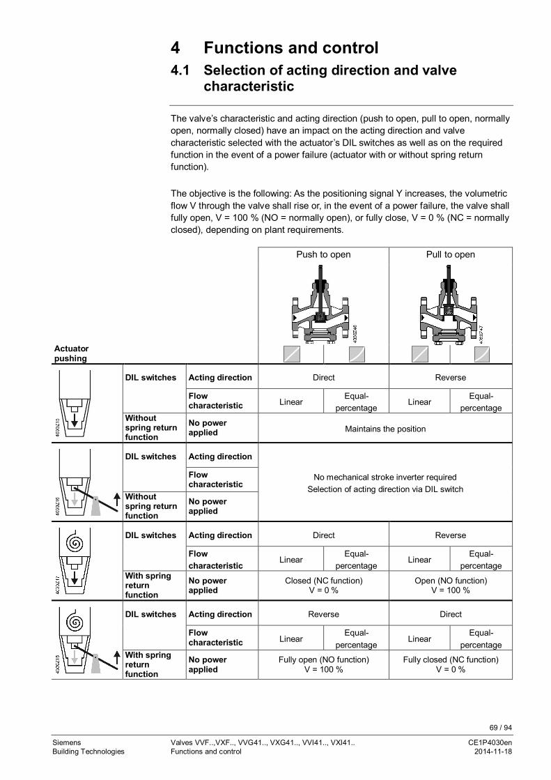
69 / 94
Siemens Valves VVF..,VXF.., VVG41.., VXG41.., VVI41.., VXI41.. CE1P4030enBuilding Technologies Functions and control 2014-11-18
4 Functions and control4.1 Selection of acting direction and valve
characteristic
The valve’s characteristic and acting direction (push to open, pull to open, normallyopen, normally closed) have an impact on the acting direction and valvecharacteristic selected with the actuator’s DIL switches as well as on the requiredfunction in the event of a power failure (actuator with or without spring returnfunction).
The objective is the following: As the positioning signal Y increases, the volumetricflow V through the valve shall rise or, in the event of a power failure, the valve shallfully open, V = 100 % (NO = normally open), or fully close, V = 0 % (NC = normallyclosed), depending on plant requirements.
Push to open Pull to open
Actuatorpushing
DIL switches Acting direction Direct Reverse
Flowcharacteristic Linear
Equal-percentage
LinearEqual-
percentageWithoutspring returnfunction
No powerapplied Maintains the position
DIL switches Acting direction
No mechanical stroke inverter requiredSelection of acting direction via DIL switch
Flowcharacteristic
Withoutspring returnfunction
No powerapplied
DIL switches Acting direction Direct Reverse
Flowcharacteristic
LinearEqual-
percentageLinear
Equal-percentage
With springreturnfunction
No powerapplied
Closed (NC function)V = 0 %
Open (NO function)V = 100 %
DIL switches Acting direction Reverse Direct
Flowcharacteristic Linear
Equal-percentage
LinearEqual-
percentageWith springreturnfunction
No powerapplied
Fully open (NO function)V = 100 %
Fully closed (NC function)V = 0 %

70 / 94
Siemens Valves VVF..,VXF.., VVG41.., VXG41.., VVI41.., VXI41.. CE1P4030enBuilding Technologies Functions and control 2014-11-18
4.2 Calibration
Calibration must be performed when valve and actuator are correctly assembled.
4.3 Technical and mechanical design
The illustrations below only show the valves’ basic design; constructional features,such as the shape of plugs, may differ.
Closing against the pressure Closing with the pressure
2-port valves do not become 3-port valves by removing the blank flange!
Mixing valve (preferred use) Diverting valve
Depending on the nominal valve size, a guided parabolic, perforated or slot plug isused – rigidly connected to the valve stem.
The seat is pressed into the valve body together with a special sealing compound.
2-port valves
Note
3-port valves

71 / 94
Siemens Valves VVF..,VXF.., VVG41.., VXG41.., VVI41.., VXI41.. CE1P4030enBuilding Technologies Functions and control 2014-11-18
4.3.1 Vales with pressure compensation
The valves VVF42...K, VVF43...K and VVF53...K are equipped with a pressure-compensated plug. Thereby volume flow rates with same actuators at higherdifferential pressure can be controlled.
Closing with the pressure
2-port valves do not become 3-port valves by removing the blank flange!
4.3.2 Plug stop
The built-in plug stop …· supports secure guidance of the plug in all stroke positions,· prevents the head of the stem from immersing into the sealing gland, thus
avoiding damage to the seal,· prevents loss of plug as long as no actuator is fitted.
4.3.3 Valve stem, valve neck, coupling
· The diameter of the valve stem is10 mm with all types of valves
· The same valve stem design ensurescompatibility with the actuators
1 Valve stem2 Valve neck3 Valve stem coupling4 Valve neck coupling
4.3.4 Converting a 2-port to a 3-port valve
It is not possible to convert a 2-port valve to a 3-port valve.
2-port valves do not become 3-port valves by removing the blank flange!
Note
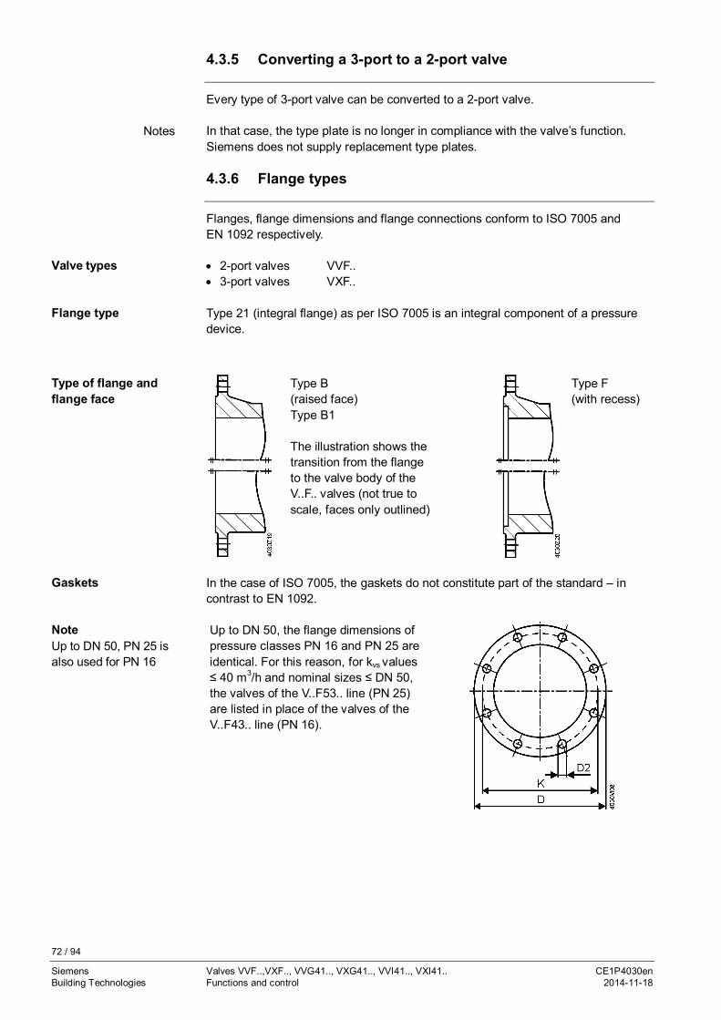
72 / 94
Siemens Valves VVF..,VXF.., VVG41.., VXG41.., VVI41.., VXI41.. CE1P4030enBuilding Technologies Functions and control 2014-11-18
4.3.5 Converting a 3-port to a 2-port valve
Every type of 3-port valve can be converted to a 2-port valve.
In that case, the type plate is no longer in compliance with the valve’s function.Siemens does not supply replacement type plates.
4.3.6 Flange types
Flanges, flange dimensions and flange connections conform to ISO 7005 andEN 1092 respectively.
· 2-port valves VVF..· 3-port valves VXF..
Type 21 (integral flange) as per ISO 7005 is an integral component of a pressuredevice.
Type B(raised face)Type B1
The illustration shows thetransition from the flangeto the valve body of theV..F.. valves (not true toscale, faces only outlined)
Type F(with recess)
In the case of ISO 7005, the gaskets do not constitute part of the standard – incontrast to EN 1092.
Up to DN 50, the flange dimensions ofpressure classes PN 16 and PN 25 areidentical. For this reason, for kvs values≤ 40 m3/h and nominal sizes ≤ DN 50,the valves of the V..F53.. line (PN 25)are listed in place of the valves of theV..F43.. line (PN 16).
Notes
Valve types
Flange type
Type of flange andflange face
Gaskets
NoteUp to DN 50, PN 25 isalso used for PN 16

73 / 94
Siemens Valves VVF..,VXF.., VVG41.., VXG41.., VVI41.., VXI41.. CE1P4030enBuilding Technologies Functions and control 2014-11-18
DN D K D2 BoltsOutside
diameter offlange
Diameter of boltcircle
Diameter ofbolt holes
Quantity Size
10 90 60 14 4 M1215 95 65 14 4 M1220 105 75 14 4 M1225 115 85 14 4 M1232 140 100 18 4 M1640 150 110 18 4 M1650 165 125 18 4 M16
The valve series VXF22, VXF32, VXF42, VXF43 and VXF53 have a greater interiordiameter in bypass port B versus the nominal value. This is not a problem whenused with any standard ISO7005 and EN1092 steel flanges but ensure that anyconnection method used is explicitly designed for a specific interior diameter iscompatible with this grater interior diameter..DN D3
Ø Inside diameter bypass-flange
VXF22 VXF32 VXF42 VXF43 VXF5315 - 23 23 - 25
20 - - 29 - 35
25 36 36 36 - 38
32 - - 46 - 46
40 52 56 56 - 57
50 65 69 69 - 69
65 85 85 85 86 86
80 98 102 102 100 100
100 116 124 124 123 123
125 - 149 149 149 149
150 - 174 174 174 174
Connectingdimensions [mm]PN 16/PN 25 to DN 50
Connecting dimensions[mm]Bypass-Port B

74 / 94
Siemens Valves VVF..,VXF.., VVG41.., VXG41.., VVI41.., VXI41.. CE1P4030enBuilding Technologies Technical data 2014-11-18
5 Technical dataV..F22.. V..F32.. V..F42.. V..F43.. V..F53.. V..G41.. V..I41..
Functiondata
PN class PN 6 PN 10 PN 16 PN 25 (PN16)
PN 16
Type of connection Flanged Externallythreaded
Internallythreaded
Operating pressure Within the range of the permissible medium temperature according to the charts on pages 51.Valve characteristic 1)
Throughport 0…30 %30…100 %
kvs = 250/360/400 m3/h
LinearEqual-percentage; ngl = 3 to VDI / VDE 2173
LinearBypass Linear
Leakagerate
Throughport 0…0.02 % of kvs value 0…0.01 % of kvs value(class IV)
0…0.02 % of kvs value
Bypass 0.5…2 % of kvs value for kVS ≥ 6.3 0.5…2 % of kvs valuewith SKD.., SKB.., andSKC..
- -
0.5…4 % ofkvs value forkVS 2.5, 4
0.5…3 % of kvsvalue for kVS
1.6, 2.5, 4
0.05 % of kvs value withSAX..
- -
VXG41..VXI41..
0.5...2 % of kvs value
VXG41..01 0...0.02 % of kvsvalue
-
MediaCold water
Low-temperature hotwater
High-temperature hotwater
Water with antifreezeCooling waterDrinking water
BrinesSaturated steam
Superheated steamHeat transfer oils
According to the table on page 12, "2.2.1 Compatibility with medium and temperature ranges"
Medium temperatureAlso refer to page 51
-10…130 °C -10…150 °C -20…220 °C 2) -25…150 °C
VVF42..K; VVF43..K,VVF53..K - - 5…150 °C -5…220 °C -
Rangeability SV
DN 15, kvs ≤ 1.25 - - -
-
> 50 > 50 > 50DN 15, kvs > 1.6 - > 50> 50
> 100
DN 20 - -
> 100 > 100DN 25 > 50 > 50DN 32 - -
> 100
DN 40
> 100> 100
DN 50DN 65
> 100 - -DN 80
DN 100DN 125 -DN 150
Nominal strokeDN 15 - 20 mm
20 mm- 20 mm 20 mm 20 mm
DN 20 -DN 25 20 mm 20 mmDN 32 - -DN 40
20 mm 20 mmDN 50DN 65
40 mm 40 mm - -DN 80
DN 100 40 mm40 mm 40 mmDN 125 -DN 150
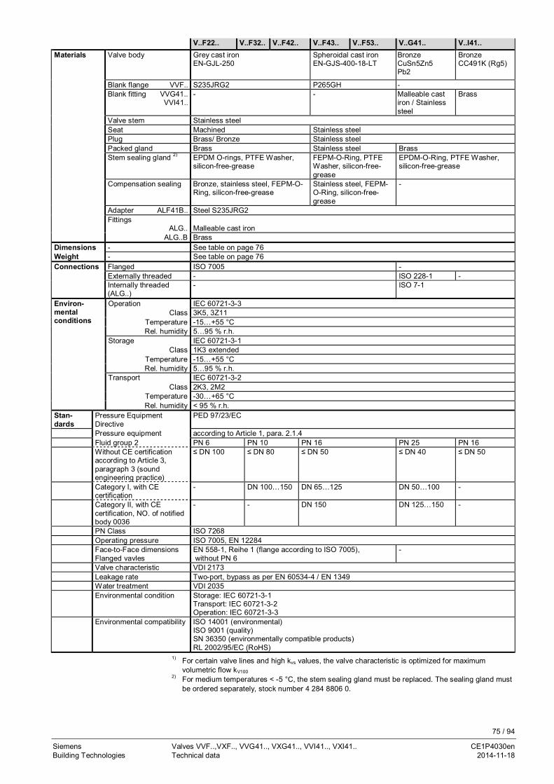
75 / 94
Siemens Valves VVF..,VXF.., VVG41.., VXG41.., VVI41.., VXI41.. CE1P4030enBuilding Technologies Technical data 2014-11-18
V..F22.. V..F32.. V..F42.. V..F43.. V..F53.. V..G41.. V..I41..Materials Valve body Grey cast iron
EN-GJL-250Spheroidal cast ironEN-GJS-400-18-LT
BronzeCuSn5Zn5Pb2
BronzeCC491K (Rg5)
Blank flange VVF.. S235JRG2 P265GH -Blank fitting VVG41..
VVI41..- - Malleable cast
iron / Stainlesssteel
Brass
Valve stem Stainless steelSeat Machined Stainless steelPlug Brass/ Bronze Stainless steelPacked gland Brass Stainless steel BrassStem sealing gland 2) EPDM O-rings, PTFE Washer,
silicon-free-greaseFEPM-O-Ring, PTFEWasher, silicon-free-grease
EPDM-O-Ring, PTFE Washer,silicon-free-grease
Compensation sealing Bronze, stainless steel, FEPM-O-Ring, silicon-free-grease
Stainless steel, FEPM-O-Ring, silicon-free-grease
-
Adapter ALF41B.. Steel S235JRG2Fittings
ALG.. Malleable cast ironALG..B Brass
Dimensions - See table on page 76Weight - See table on page 76Connections Flanged ISO 7005 -
Externally threaded - ISO 228-1 -Internally threaded(ALG..)
- ISO 7-1
Environ-mentalconditions
Operation IEC 60721-3-3Class 3K5, 3Z11
Temperature -15…+55 °CRel. humidity 5…95 % r.h.
Storage IEC 60721-3-1Class 1K3 extended
Temperature -15…+55 °CRel. humidity 5…95 % r.h.
Transport IEC 60721-3-2Class 2K3, 2M2
Temperature -30…+65 °CRel. humidity < 95 % r.h.
Stan-dards
Pressure EquipmentDirective
PED 97/23/EC
Pressure equipment according to Article 1, para. 2.1.4Fluid group 2 PN 6 PN 10 PN 16 PN 25 PN 16Without CE certificationaccording to Article 3,paragraph 3 (soundengineering practice)
≤ DN 100 ≤ DN 80 ≤ DN 50 ≤ DN 40 ≤ DN 50
Category I, with CEcertification
- DN 100…150 DN 65…125 DN 50…100 -
Category II, with CEcertification, NO. of notifiedbody 0036
- - DN 150 DN 125…150 -
PN Class ISO 7268Operating pressure ISO 7005, EN 12284Face-to-Face dimensionsFlanged vavles
EN 558-1, Reihe 1 (flange according to ISO 7005), without PN 6
-
Valve characteristic VDI 2173Leakage rate Two-port, bypass as per EN 60534-4 / EN 1349Water treatment VDI 2035Environmental condition Storage: IEC 60721-3-1
Transport: IEC 60721-3-2Operation: IEC 60721-3-3
Environmental compatibility ISO 14001 (environmental)ISO 9001 (quality)SN 36350 (environmentally compatible products)RL 2002/95/EC (RoHS)
1) For certain valve lines and high kvs values, the valve characteristic is optimized for maximumvolumetric flow kV100
2) For medium temperatures < -5 °C, the stem sealing gland must be replaced. The sealing gland mustbe ordered separately, stock number 4 284 8806 0.

76 / 94
Siemens Valves VVF..,VXF.., VVG41.., VXG41.., VVI41.., VXI41.. CE1P4030enBuilding Technologies Dimensions 2014-11-18
6 Dimensions
Dimensions in mm, weight in kg
Productnumber DN B Ø D Ø D1 Ø D2 L1 L2 L3 Ø K H1 H2 H
SAX.. SKD.. SKB.. SKC..VVF22.. 25 4.1 11 100 58 11 (4x) 150 75 99 75 37 133.5 479 537 612 -
40 6.5 13 130 78 14 (4x) 180 90 116 100 37 133.5 479 537 612 -50 8 14 140 88 14 (4x) 200 100 128 110 50 146.5 492 550 625 -65 11.9 14 160 108 14 (4x) 240 120 142.5 130 75 171.5 517 575 650 -80 17.1 16 190 124 19 (4x) 260 130 157 150 75 171.5 517 575 650 -100 23.8 16 210 144 19 (4x) 300 150 179 170 110 226.5 - - - 685
Productnumber DN B Ø D Ø D1 Ø D2 L1 L2 L3 Ø K H1 H2 H
SAX.. SKD.. SKB.. SKC..VVF32.. 15 3.7 14 95 46 14 (4x) 130 65 86 65 37 133.5 479 537 612 -
20 - - - - - - - - - - - - - - -25 5.4 15 115 65 14 (4x) 160 80 104 85 37 133.5 479 537 612 -32 - - - - - - - - - - - - - - -40 9.3 16 150 84 19 (4x) 200 100 126 110 37 133.5 479 537 612 -50 12.2 16 165 99 19 (4x) 230 115 143 125 50 146.5 492 550 625 -65 17 17 185 118 19 (4x) 290 145 173 145 75 171.5 517 575 650 -80 25 17 200 132 19 (8x) 310 155 185 160 75 171.5 517 575 650 -100 35.7 17 220 156 19 (8x) 350 175 205 180 110 226.5 - - - 685125 52.5 17 250 184 19 (8x) 400 200 232 210 123 239.5 - - - 698150 74.3 17 284 211 23 (8x) 480 240 275 240 150.5 267 - - - 726
Note
VVF22..
VVF32..

77 / 94
Siemens Valves VVF..,VXF.., VVG41.., VXG41.., VVI41.., VXI41.. CE1P4030enBuilding Technologies Dimensions 2014-11-18
Productnumber DN B Ø D Ø D1 Ø D2 L1 L2 L3 Ø K H1 H2 H
SAX.. SKD.. SKB.. SKC..VVF42.. 15 3.7 14 95 46 14 (4x) 130 65 86 65 37 133.5 479 537 612 -
20 4.7 16 105 56 14 (4x) 150 75 97 75 37 133.5 479 537 612 -25 5.4 15 115 65 14 (4x) 160 80 106.5 85 37 133.5 479 537 612 -32 8.4 17 140 76 19 (4x) 180 90 119 100 37 133.5 479 537 612 -40 9.3 16 150 84 19 (4x) 200 100 126 110 37 133.5 479 537 612 -50 12.2 16 165 99 19 (4x) 230 115 144 125 50 146.5 492 550 625 -65 17 17 185 118 19 (4x) 290 145 174 145 75 171.5 517 575 650 -80 25 17 200 132 19 (8x) 310 155 186 160 75 171.5 517 575 650 -100 35.7 17 220 156 19 (8x) 350 175 205 180 110 226.5 - - - 685125 52.5 17 250 184 19 (8x) 400 200 233 210 123 239.5 - - - 698150 74.3 17 284 211 23 (8x) 480 240 275.5 240 150.5 267 - - - 726
Productnumber DN B Ø D Ø D1 Ø D2 L1 L2 L3 Ø K H1 H2 H
SAX.. SKD.. SKB.. SKC..VVF43.. 65 21.8 17 185 118 19 (4x) 290 145 178 145 115 231.5 - - - 690
80 27.7 17 200 132 19 (8x) 310 155 190 160 115 231.5 - - - 690100 33.6 17 220 156 19 (8x) 350 175 206 180 146 262.5 - - - 721125 50 17 250 184 19 (8x) 400 200 233 210 159 275.5 - - - 734150 66.3 17 284 211 23 (8x) 480 240 275.5 240 186.5 303 - - - 762
VVF43..K 65 22.0 17 185 118 19 (4x) 290 145 178 145 115 231.5 - - - 69080 27.9 17 200 132 19 (8x) 310 155 190 160 115 231.5 - - - 690100 33.9 17 220 156 19 (8x) 350 175 206 180 146 262.5 - - - 721125 46.9 17 250 184 19 (8x) 400 200 233 210 159 275.5 - - - 734150 67.7 17 284 211 23 (8x) 480 240 275.5 240 186.5 303 - - - 762
VVF42..
VVF43..VVF43..K

78 / 94
Siemens Valves VVF..,VXF.., VVG41.., VXG41.., VVI41.., VXI41.. CE1P4030enBuilding Technologies Dimensions 2014-11-18
Productnumber DN B Ø D Ø D1 Ø D2 L1 L2 L3 Ø K H1 H2 H
SAX.. SKD.. SKB.. SKC..VVF53.. 15 4.2 14 95 46 14 (4x) 130 65 87.5 65 63 159.5 505 563 638 -
20 5.4 16 105 56 14 (4x) 150 75 99.5 75 63 159.5 505 563 638 -25 6.1 15 115 65 14 (4x) 160 80 104.5 85 63 159.5 505 563 638 -32 8.8 17 140 76 19 (4x) 180 90 119 100 60 156.5 502 560 635 -40 10.2 16 150 84 19 (4x) 200 100 129 110 60 156.5 502 560 635 -50 13.7 16 165 99 19 (4x) 230 115 146 125 100 196.5 542 600 675 -65 22.2 17 185 118 19 (8x) 290 145 178 145 115 231.5 - - - 69080 27.7 17 200 132 19 (8x) 310 155 190 160 115 231.5 - - - 690100 38.6 17 235 156 23 (8x) 350 175 212.5 190 146 262.5 - - - 721125 54.4 17 270 184 28 (8x) 400 200 242 220 159 275.5 - - - 734150 74.3 17 297 211 28 (8x) 480 240 284 250 186.5 303 - - - 762
VVF53..K 50 13.6 16 165 99 19 (4x) 230 115 146 125 100 196.5 542 600 675 -65 22.3 17 185 118 19 (8x) 290 145 178 145 115 231.5 - - - 69080 27.9 17 200 132 19 (8x) 310 155 190 160 115 231.5 - - - 690100 39.0 17 235 156 23 (8x) 350 175 212.5 190 146 262.5 - - - 721125 54.4 17 270 184 28 (8x) 400 200 242 220 159 275.5 - - - 734150 75.8 17 297 211 28 (8x) 480 240 284 250 186.5 303 - - - 762
Productnumber
DN G L1 L2 L3 H1 H2 H
[Inch] SAX.. SKD.. SKB..VVG41.. 15 1.25 G 1B
100 50 57 26 122,5 > 468 > 526 > 60120 1.3 G 1¼B25 1.6 G 1½B
105 52.559
34 130,5 > 476 > 534 > 60932 2.2 G 2B 6040 2.7 G 2¼B 130 65 73
46 142,5 > 488 > 546 > 62150 3.9 G 2¾B 150 75 83
VVF53..VVF53..K
VVG41..
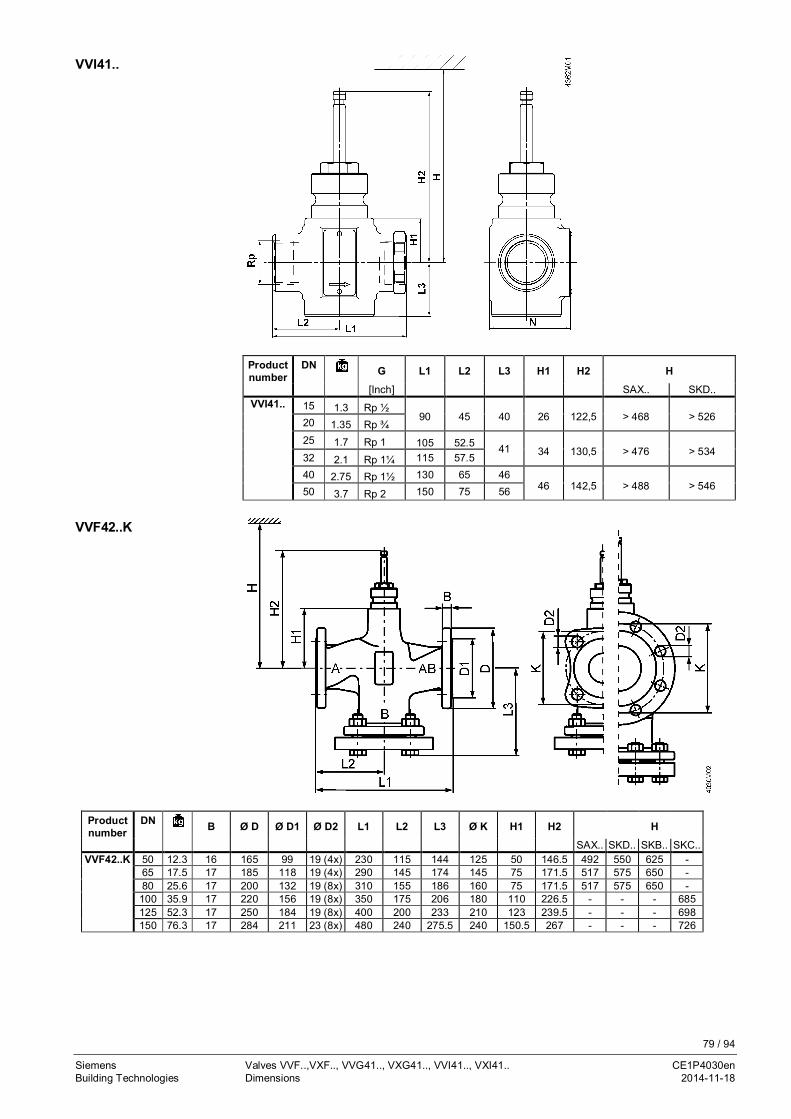
79 / 94
Siemens Valves VVF..,VXF.., VVG41.., VXG41.., VVI41.., VXI41.. CE1P4030enBuilding Technologies Dimensions 2014-11-18
Productnumber
DN G L1 L2 L3 H1 H2 H
[Inch] SAX.. SKD..VVI41.. 15 1.3 Rp ½
90 45 40 26 122,5 > 468 > 52620 1.35 Rp ¾25 1.7 Rp 1 105 52.5 41 34 130,5 > 476 > 53432 2.1 Rp 1¼ 115 57.540 2.75 Rp 1½ 130 65 46
46 142,5 > 488 > 54650 3.7 Rp 2 150 75 56
Productnumber
DN B Ø D Ø D1 Ø D2 L1 L2 L3 Ø K H1 H2 H
SAX.. SKD.. SKB.. SKC..VVF42..K 50 12.3 16 165 99 19 (4x) 230 115 144 125 50 146.5 492 550 625 -
65 17.5 17 185 118 19 (4x) 290 145 174 145 75 171.5 517 575 650 -80 25.6 17 200 132 19 (8x) 310 155 186 160 75 171.5 517 575 650 -100 35.9 17 220 156 19 (8x) 350 175 206 180 110 226.5 - - - 685125 52.3 17 250 184 19 (8x) 400 200 233 210 123 239.5 - - - 698150 76.3 17 284 211 23 (8x) 480 240 275.5 240 150.5 267 - - - 726
VVI41..
VVF42..K
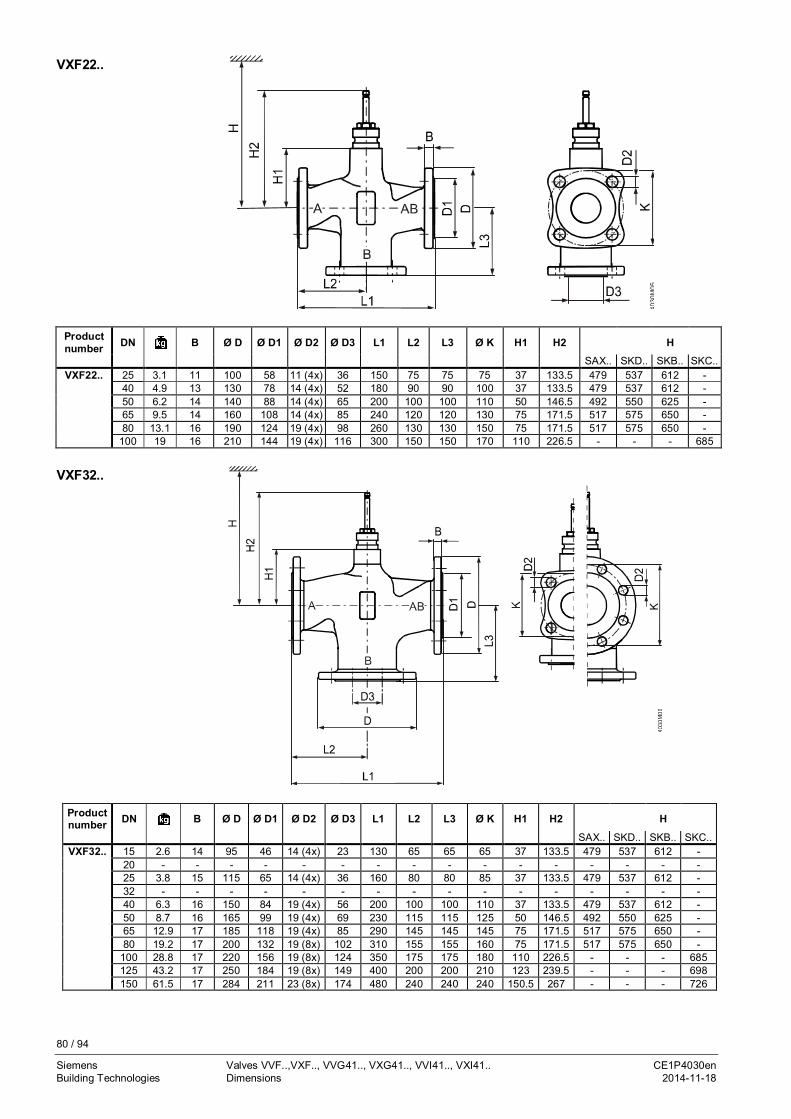
80 / 94
Siemens Valves VVF..,VXF.., VVG41.., VXG41.., VVI41.., VXI41.. CE1P4030enBuilding Technologies Dimensions 2014-11-18
Productnumber DN B Ø D Ø D1 Ø D2 Ø D3 L1 L2 L3 Ø K H1 H2 H
SAX.. SKD.. SKB.. SKC..VXF22.. 25 3.1 11 100 58 11 (4x) 36 150 75 75 75 37 133.5 479 537 612 -
40 4.9 13 130 78 14 (4x) 52 180 90 90 100 37 133.5 479 537 612 -50 6.2 14 140 88 14 (4x) 65 200 100 100 110 50 146.5 492 550 625 -65 9.5 14 160 108 14 (4x) 85 240 120 120 130 75 171.5 517 575 650 -80 13.1 16 190 124 19 (4x) 98 260 130 130 150 75 171.5 517 575 650 -
100 19 16 210 144 19 (4x) 116 300 150 150 170 110 226.5 - - - 685
Productnumber DN B Ø D Ø D1 Ø D2 Ø D3 L1 L2 L3 Ø K H1 H2 H
SAX.. SKD.. SKB.. SKC..VXF32.. 15 2.6 14 95 46 14 (4x) 23 130 65 65 65 37 133.5 479 537 612 -
20 - - - - - - - - - - - - - - - -25 3.8 15 115 65 14 (4x) 36 160 80 80 85 37 133.5 479 537 612 -32 - - - - - - - - - - - - - - - -40 6.3 16 150 84 19 (4x) 56 200 100 100 110 37 133.5 479 537 612 -50 8.7 16 165 99 19 (4x) 69 230 115 115 125 50 146.5 492 550 625 -65 12.9 17 185 118 19 (4x) 85 290 145 145 145 75 171.5 517 575 650 -80 19.2 17 200 132 19 (8x) 102 310 155 155 160 75 171.5 517 575 650 -
100 28.8 17 220 156 19 (8x) 124 350 175 175 180 110 226.5 - - - 685125 43.2 17 250 184 19 (8x) 149 400 200 200 210 123 239.5 - - - 698150 61.5 17 284 211 23 (8x) 174 480 240 240 240 150.5 267 - - - 726
VXF22..
VXF32..
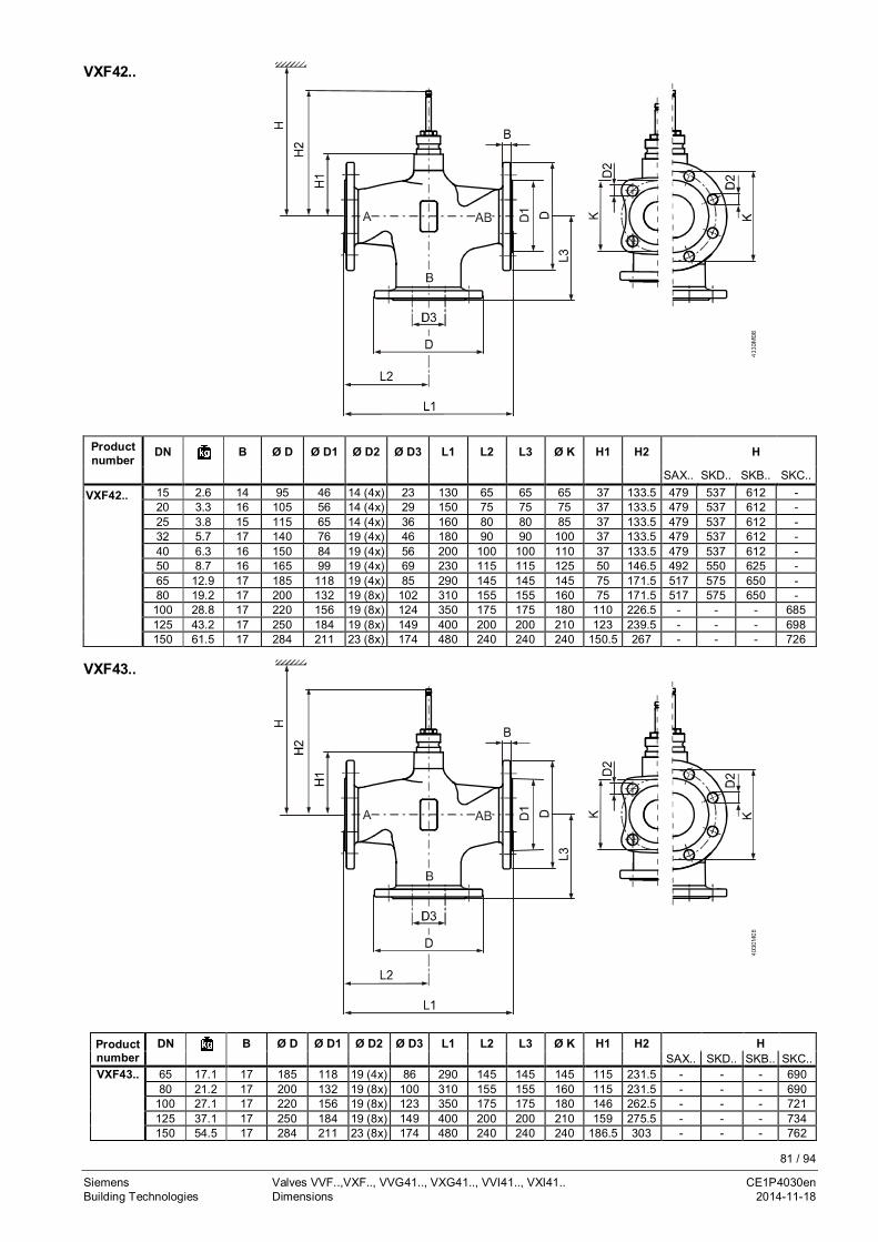
81 / 94
Siemens Valves VVF..,VXF.., VVG41.., VXG41.., VVI41.., VXI41.. CE1P4030enBuilding Technologies Dimensions 2014-11-18
Productnumber
DN B Ø D Ø D1 Ø D2 Ø D3 L1 L2 L3 Ø K H1 H2 H
SAX.. SKD.. SKB.. SKC..
VXF42.. 15 2.6 14 95 46 14 (4x) 23 130 65 65 65 37 133.5 479 537 612 -20 3.3 16 105 56 14 (4x) 29 150 75 75 75 37 133.5 479 537 612 -25 3.8 15 115 65 14 (4x) 36 160 80 80 85 37 133.5 479 537 612 -32 5.7 17 140 76 19 (4x) 46 180 90 90 100 37 133.5 479 537 612 -40 6.3 16 150 84 19 (4x) 56 200 100 100 110 37 133.5 479 537 612 -50 8.7 16 165 99 19 (4x) 69 230 115 115 125 50 146.5 492 550 625 -65 12.9 17 185 118 19 (4x) 85 290 145 145 145 75 171.5 517 575 650 -80 19.2 17 200 132 19 (8x) 102 310 155 155 160 75 171.5 517 575 650 -100 28.8 17 220 156 19 (8x) 124 350 175 175 180 110 226.5 - - - 685125 43.2 17 250 184 19 (8x) 149 400 200 200 210 123 239.5 - - - 698150 61.5 17 284 211 23 (8x) 174 480 240 240 240 150.5 267 - - - 726
Productnumber
DN B Ø D Ø D1 Ø D2 Ø D3 L1 L2 L3 Ø K H1 H2 HSAX.. SKD.. SKB.. SKC..
VXF43.. 65 17.1 17 185 118 19 (4x) 86 290 145 145 145 115 231.5 - - - 69080 21.2 17 200 132 19 (8x) 100 310 155 155 160 115 231.5 - - - 690
100 27.1 17 220 156 19 (8x) 123 350 175 175 180 146 262.5 - - - 721125 37.1 17 250 184 19 (8x) 149 400 200 200 210 159 275.5 - - - 734150 54.5 17 284 211 23 (8x) 174 480 240 240 240 186.5 303 - - - 762
VXF42..
VXF43..

82 / 94
Siemens Valves VVF..,VXF.., VVG41.., VXG41.., VVI41.., VXI41.. CE1P4030enBuilding Technologies 2014-11-18
Productnumber
DN B Ø D Ø D1 Ø D2 Ø D3 L1 L2 L3 Ø K H1 H2 HSAX.. SKD.. SKB.. SKC..
VXF53.. 15 3.2 14 95 46 14 (4x) 25 130 65 65 65 63 159.5 505 563 638 -20 4.1 16 105 56 14 (4x) 35 150 75 75 75 63 159.5 505 563 638 -25 4.6 15 115 65 14 (4x) 38 160 80 80 85 63 159.5 505 563 638 -32 6.1 17 140 76 19 (4x) 46 180 90 90 100 60 156.5 502 560 635 -40 7.2 16 150 84 19 (4x) 57 200 100 100 110 60 156.5 502 560 635 -50 9.8 16 165 99 19 (4x) 69 230 115 115 125 100 196.5 542 600 675 -65 16.8 17 185 118 19 (8x) 86 290 145 145 145 115 231.5 - - - 69080 21.2 17 200 132 19 (8x) 100 310 155 155 160 115 231.5 - - - 690
100 29 17 235 156 23 (8x) 123 350 175 175 190 146 262.5 - - - 721125 39.7 17 270 184 28 (8x) 149 400 200 200 220 159 275.5 - - - 734150 57 17 297 211 28 (8x) 174 480 240 240 250 186.5 303 - - - 762
Productnumber
DN G L1 L2 L3 H1 H2 H[Inch] SAX.. SKD.. SKB..
VXG41.. 15 1.3 G 1B100 50 50 26 122.5 > 468 > 526 > 60120 1.42 G 1¼B
25 1.65 G 1½B105 52.5 52.5 34 130.5 > 476 > 534 > 60932 2.1 G 2B
40 2.8 G 2¼B 130 65 6546 142.5 > 488 > 546 > 62150 3.9 G 2¾B 150 75 75
VXF53..
VXG41..

83 / 94
Siemens Valves VVF..,VXF.., VVG41.., VXG41.., VVI41.., VXI41.. CE1P4030enBuilding Technologies 2014-11-18
Productnumber
DN G L1 L2 L3 H1 H2 H
[Inch] SAX.. SKD..VVI41.. 15 1.5 Rp ½
90 4568
26 122.5 > 468 > 52620 1.6 Rp ¾ 69
25 2.1 Rp 1 105 52.5 73.534 130.5 > 476 > 53432 2.3 Rp 1¼ 115 57.5 74
40 3.1 Rp 1½ 130 65 84 46 142.5 > 488 > 546
VXI41..
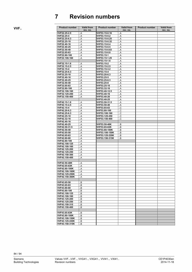
84 / 94
Siemens Valves VVF..,VXF.., VVG41.., VXG41.., VVI41.., VXI41.. CE1P4030enBuilding Technologies Revision numbers 2014-11-18
7 Revision numbersProduct number Valid from
rev. no.Product number Valid from
rev. no.Product number Valid from
rev. no.VVF22.25-2.5 ..A VVF53.15-0.16 ..AVVF22.25-4 ..A VVF53.15-0.2 ..AVVF22.25-6.3 ..A VVF53.15-0.25 ..AVVF22.25-10 ..A VVF53.15-0.32 ..AVVF22.40-16 ..A VVF53.15-0.4 ..AVVF22.40-25 ..A VVF53.15-0.5 ..AVVF22.50-40 ..A VVF53.15-0.63 ..AVVF22.65-63 ..A VVF53.15-0.8 ..AVVF22.80-100 ..A VVF53.15-1 ..AVVF22.100-160 ..A VVF53.15-1.25 ..A
VVF53.15-1.6 ..AVVF32.15-1.6 ..A VVF53.15-2 ..AVVF32.15-2.5 ..A VVF53.15-2.5 ..AVVF32.15-4 ..A VVF53.15-3.2 ..AVVF32.25-6.3 ..A VVF53.15-4 ..AVVF32.25-10 ..A VVF53.20-6.3 ..AVVF32.40-16 ..A VVF53.25-5 ..AVVF32.40-25 ..A VVF53.25-6.3 ..AVVF32.50-40 ..A VVF53.25-8 ..AVVF32.65-63 ..A VVF53.25-10 ..AVVF32.80-100 ..A VVF53.32-16 ..AVVF32.100-160 ..A VVF53.40-12.5 ..AVVF32.125-250 ..A VVF53.40-16 ..AVVF32.150-400 ..A VVF53.40-20 ..A
VVF53.40-25 ..AVVF42.15-1.6 ..A VVF53.50-31.5 ..AVVF42.15-2,5 ..A VVF53.50-40 ..AVVF42.15-4 ..A VVF53.65-63 ..CVVF42.20-6.3 ..A VVF53.80-100 ..CVVF42.25-6.3 ..A VVF53.100-160 ..CVVF42.25-10 ..A VVF53.125-250 ..CVVF42.32-16 ..A VVF53.150-400 ..CVVF42.40-16 ..AVVF42.40-25 ..A VVF53.50-40K ..BVVF42.50-31.5 ..A VVF53.65-63K ..BVVF42.50-40 ..A VVF53.80-100K ..BVVF42.65-50 ..A VVF53.100-150K ..BVVF42.65-63 ..A VVF53.125-220K ..BVVF42.80-80 ..A VVF53.150-315K ..BVVF42.80-100 ..AVVF42.100-125 ..AVVF42.100-160 ..AVVF42.125-200 ..AVVF42.125-250 ..AVVF42.150-300 ..AVVF42.150-400 ..A
VVF42.50-40K ..AVVF42.65-63K ..AVVF42.80-100K ..AVVF42.100-160K ..AVVF42.125-250K ..AVVF42.150-360K ..A
VVF43.65-50 ..BVVF43.65-63 ..BVVF43.80-80 ..BVVF43.80-100 ..BVVF43.100-125 ..BVVF43.100-160 ..BVVF43.125-200 ..BVVF43.125-250 ..BVVF43.150-315 ..BVVF43.150-400 ..B
VVF43.65-63K ..BVVF43.80-100K ..BVVF43.100-150K ..BVVF43.125-220K ..BVVF43.150-315K ..B
VVF..
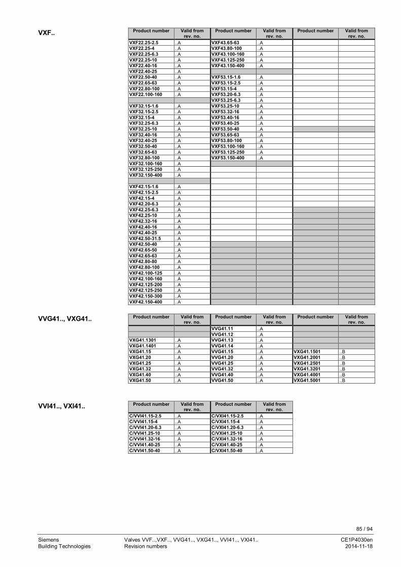
85 / 94
Siemens Valves VVF..,VXF.., VVG41.., VXG41.., VVI41.., VXI41.. CE1P4030enBuilding Technologies Revision numbers 2014-11-18
Product number Valid fromrev. no.
Product number Valid fromrev. no.
Product number Valid fromrev. no.
VXF22.25-2.5 ..A VXF43.65-63 ..AVXF22.25-4 ..A VXF43.80-100 ..AVXF22.25-6.3 ..A VXF43.100-160 ..AVXF22.25-10 ..A VXF43.125-250 ..AVXF22.40-16 ..A VXF43.150-400 ..AVXF22.40-25 ..AVXF22.50-40 ..A VXF53.15-1.6 ..AVXF22.65-63 ..A VXF53.15-2.5 ..AVXF22.80-100 ..A VXF53.15-4 ..AVXF22.100-160 ..A VXF53.20-6.3 ..A
VXF53.25-6.3 ..AVXF32.15-1.6 ..A VXF53.25-10 ..AVXF32.15-2.5 ..A VXF53.32-16 ..AVXF32.15-4 ..A VXF53.40-16 ..AVXF32.25-6.3 ..A VXF53.40-25 ..AVXF32.25-10 ..A VXF53.50-40 ..AVXF32.40-16 ..A VXF53.65-63 ..AVXF32.40-25 ..A VXF53.80-100 ..AVXF32.50-40 ..A VXF53.100-160 ..AVXF32.65-63 ..A VXF53.125-250 ..AVXF32.80-100 ..A VXF53.150-400 ..AVXF32.100-160 ..AVXF32.125-250 ..AVXF32.150-400 ..A
VXF42.15-1.6 ..AVXF42.15-2.5 ..AVXF42.15-4 ..AVXF42.20-6.3 ..AVXF42.25-6.3 ..AVXF42.25-10 ..AVXF42.32-16 ..AVXF42.40-16 ..AVXF42.40-25 ..AVXF42.50-31.5 ..AVXF42.50-40 ..AVXF42.65-50 ..AVXF42.65-63 ..AVXF42.80-80 ..AVXF42.80-100 ..AVXF42.100-125 ..AVXF42.100-160 ..AVXF42.125-200 ..AVXF42.125-250 ..AVXF42.150-300 ..AVXF42.150-400 ..A
Product number Valid fromrev. no.
Product number Valid fromrev. no.
Product number Valid fromrev. no.
VVG41.11 ..AVVG41.12 ..A
VXG41.1301 ..A VVG41.13 ..AVXG41.1401 ..A VVG41.14 ..AVXG41.15 ..A VVG41.15 ..A VXG41.1501 ..BVXG41.20 ..A VVG41.20 ..A VXG41.2001 ..BVXG41.25 ..A VVG41.25 ..A VXG41.2501 ..BVXG41.32 ..A VVG41.32 ..A VXG41.3201 ..BVXG41.40 ..A VVG41.40 ..A VXG41.4001 ..BVXG41.50 ..A VVG41.50 ..A VXG41.5001 ..B
Product number Valid fromrev. no.
Product number Valid fromrev. no.
C/VVI41.15-2.5 ..A C/VXI41.15-2.5 ..AC/VVI41.15-4 ..A C/VXI41.15-4 ..AC/VVI41.20-6.3 ..A C/VXI41.20-6.3 ..AC/VVI41.25-10 ..A C/VXI41.25-10 ..AC/VVI41.32-16 ..A C/VXI41.32-16 ..AC/VVI41.40-25 ..A C/VXI41.40-25 ..AC/VVI41.50-40 ..A C/VXI41.50-40 ..A
VXF..
VVG41.., VXG41..
VVI41.., VXI41..

86 / 94
Siemens Valves VVF..,VXF.., VVG41.., VXG41.., VVI41.., VXI41.. CE1P4030enBuilding Technologies Addendum 2014-11-18
8 Addendum8.1.1 Abbreviations
Abbreviation Unit Term Explanationc [kJ/kgK] Specific heat capacity See "Specific heat capacity", page 87DN - Nominal size Characteristic for matching parts of a piping systemFR - Correction factor Factor for impact of valve’s Reynolds numberH [mm] Stroke Travel of valve or actuator stemH0 [m] Shutoff head Pump head when medium is supplied. The head
generated by a pump when the valve is fully closedkv [m3/h] Nominal flow Amount of cold water (5…30 °C) passing through the
valve at the respective stroke and at a differentialpressure of 100 kPa (1 bar)
kvr [m3/h] - Smallest volumetric flow that can be controlled, thatis, when the valve starts to open (opening step)
kvs [m3/h] Nominal flow Nominal flow rate of cold water (5…30 °C) throughthe fully open valve (H100) at a differential pressure of100 kPa (1 bar)
m [kg/h] Mass flowSteam mass flow
-
PN - PN class Characteristic relating to the combination ofmechanical and dimensional properties of acomponent in a piping system
Pv - Valve authority See "Valve authority Pv", page 87Q100 [kW] Rated capacity Design capacity of plantQmin [kW] Smallest output of a consumer that can be controlled
in modulating moderp1 [kJ/kgK] Specific heat capacity of steamSv - Rangeability See "Rangeability SV", page 87V100 [m3/h],
[l/s]Volumetric flow Volume per unit of time through the fully open valve
(H100)ρ [kg/m3] Density Mass per volumeυ [mm2/s],
[cSt]Kinematic viscosity 1 mm2/s = 1 cSt (centistoke), also refer to 2.8.3.3
Kinematic viscosity ν, page 38Dp [kPa] Differential pressure Pressure difference between plant sectionsDpmax [kPa] Max. differential
pressureMaximum permissible differential pressure acrossthe valve’s throughport (control path) for the entirepositioning range of the motorized valve
DpMV [kPa] - Differential pressure across the section with variableflow
Dps [kPa] Closing pressure Maximum permissible differential pressure at whichthe motorized valve still closes securely against thepressure
Dpv0 [kPa] - Maximum differential pressure across the valve’sfully closed throughport (control path)
Dpv100 [kPa] Differential pressure atnominal flow rate
Differential pressure across the fully open valve andthe valve’s throughport A – AB at the volumetric flowV100
DpVR [kPa] - Differential pressure of flow and returnDT [K] Temperature spread Temperature difference of flow and return
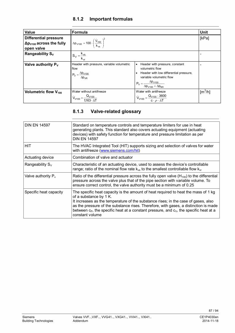
87 / 94
Siemens Valves VVF..,VXF.., VVG41.., VXG41.., VVI41.., VXI41.. CE1P4030enBuilding Technologies Addendum 2014-11-18
8.1.2 Important formulas
Value Formula UnitDifferential pressureΔpV100 across the fullyopen valve
2
vs
100100V k
V100p ÷
÷ø
öççè
æ×=D
& [kPa]
Rangeability SV
vr
vsV k
kS = -
Valve authority PV Header with pressure, variable volumetricflow
VR
100VV p
pPD
D=
· Header with pressure, constantvolumetric flow
· Header with low differential pressure,variable volumetric flow
MV100V
100VV pp
pPD+D
D=
-
Volumetric flow V100 Water without antifreeze
T163,1QV 100V
100V D×=&
Water with antifreeze
Tc3600QV 100V
100V D×××
=r
&
[m3/h]
8.1.3 Valve-related glossary
DIN EN 14597 Standard on temperature controls and temperature limiters for use in heatgenerating plants. This standard also covers actuating equipment (actuatingdevices) with safety function for temperature and pressure limitation as perDIN EN 14597
HIT The HVAC Integrated Tool (HIT) supports sizing and selection of valves for waterwith antifreeze (www.siemens.com/hit)
Actuating device Combination of valve and actuator
Rangeability SV Characteristic of an actuating device, used to assess the device’s controllablerange; ratio of the nominal flow rate kvs to the smallest controllable flow kvr
Valve authority Pv Ratio of the differential pressure across the fully open valve (H100) to the differentialpressure across the valve plus that of the pipe section with variable volume. Toensure correct control, the valve authority must be a minimum of 0.25
Specific heat capacity The specific heat capacity is the amount of heat required to heat the mass of 1 kgof a substance by 1 K.It increases as the temperature of the substance rises; in the case of gases, alsoas the pressure of the substance rises. Therefore, with gases, a distinction is madebetween cP, the specific heat at a constant pressure, and cV, the specific heat at aconstant volume

88 / 94
Siemens Valves VVF..,VXF.., VVG41.., VXG41.., VVI41.., VXI41.. CE1P4030enBuilding Technologies Addendum 2014-11-18
8.1.4 Hydraulics-related glossary
Film temperature Temperature of the valve surfaces that are in contact with the heat transfer oil atwhich the oil starts to disintegrate
Cavitation Due to high speeds of the medium in the narrowest section of the valve, localunderpressure occurs. If this pressure drops below the medium’s boiling pressure,cavitation occurs (steam bubbles), possibly leading to material removal (abrasion).Also, when cavitation starts, the noise level increases abruptly. Cavitation can beavoided by limiting the pressure differential across the valve as a function of themedium temperature and the prepressure. For more detailed information, refer to"2.13 Cavitation", page 56
Selection of valvecharacteristic
Certain types of Siemens actuators are equipped with DIL switches for theselection of a linear or an equal-percentage valve characteristic. The objective is tolinearize the volumetric flow through the consumer and the valve
Closed circuit The medium circulates in a closed hydraulic system with no contact to theatmosphere
Open circuit The circulating medium is in contact with the atmosphere, that is, the hydraulicsystem is open to atmosphere (e.g. cooling towers with open tanks, or showers).Hence, the system can absorb oxygen from the surrounding air, which can lead torust; in addition, more attention is to be paid to cavitation; for more information,refer to "2.13 Cavitation", page 56
Control stability The stability of a closed control loop depends on the degree of difficulty S of thecontrolled system and the circuit amplification V0. For more detailed information,refer to the Siemens brochure "Control technology" (ordering no. 0-91913-en)
Return temperature TRL Temperature of the medium at which it returns from the consumer to the heat orcooling source
Gravity circulation The density of a medium depends on its temperature. If a medium is hot in oneplace and cold in another, it starts to circulate due to different densities
Volumetric flow V Volume of a medium that passes through an opening for a certain time
Flow temperature TVL Temperature of a heating or cooling medium at which it leaves its source to enter ahydraulic circuit
Selection of actingdirection
Certain types of Siemens actuators are equipped with DIL switches for selection ofthe operating action of the respective valve (push to open, pull to open, normallyopen, normally closed). The objective is to drive the valve to the fully open or fullyclosed position should a power failure occur, depending on plant requirements
Forced control If forced control is demanded, no consideration is given to any other controlcommand. For example, if there is risk of frost, more heat is supplied to preventfreeze-ups

89 / 94
Siemens Valves VVF..,VXF.., VVG41.., VXG41.., VVI41.., VXI41.. CE1P4030enBuilding Technologies Addendum 2014-11-18
8.1.5 Media-related glossary
Enthalpy Amount of energy contained in a thermodynamic system (heat content)
FDA Food and Drug Administration (USA)
Saturated steam Boundary between wet and superheated steam;Wet steam: Parts of the gaseous water condensate to become very fine
dropletsSuperheated steam: "Dry" steam without water droplets
Brine Solution consisting of salt and water
Heat transfer oil/thermaloil
Heat transfer fluid on the basis of mineral oil, synthetic, organic, or on the basis ofsilicon, uniform or mixed
Water Chemical compound consisting of oxygen (O) and hydrogen (H). Also refer to VDI2035 for information on avoiding damage to drinking and domestic hot water plants
Water with antifreeze The water contains an antifreeze which also inhibits corrosion. For the types ofantifreeze used in the trade, also refer to chapter "8.1.7 Overview of antifreeze andbrines used in the trade", page 89
Glycol Glycol is added to water to lower the water’s melting point. Examples are ethyleneglycol and propylene glycol. Refer to chapter "8.1.7 Overview of antifreeze andbrines used in the trade", page 89
Water, deionized The ions of salts contained in the water have been removed
Water, demineralized The minerals contained in the water have been removed
Water, super-clean water Specially treated water; various processes are used to remove dissolved salts andother undesirable substances. It has a high specific resistance and contains noorganic substances
8.1.6 Trade names
Trademark Legal owner
Acvatix Siemens
Glythermin BASF
Antifrogen, Protectogen Clariant
Dowcal Dow
Zitrec, Freezium Arteco NV/SA
TYFOCOR, TYFOXIT Tyforop Chemie GmbH
GLYKOSOL, PEKASOL, PEKASOLar Glykol & Sole GmbH
Temper Temper Technology
8.1.7 Overview of antifreeze and brines used in the trade
The list below is not exhaustive. It specifies manufacturer data and is not to beregarded as an official approval for Siemens products in the indicated temperaturerange. For temperature ranges of individual product lines, see chapter 2.12, page50.The notes given under "2.14 Medium quality and medium treatment", page 57 mustalso be observed.

90 / 94
Siemens Valves VVF..,VXF.., VVG41.., VXG41.., VVI41.., VXI41.. CE1P4030enBuilding Technologies Addendum 2014-11-18
Supplier Product number Basic medium Permissible limitweight fractions
Temperature rangeof medium
UsageW
ater
with
antif
reez
e
BASF
www.basf.com
Glythermin® NF Heat transfer medium on the basis ofethylene glycol and inhibitors
- -35…150 °C No knownrestriction
Glythermin® P 44-00 Basis: Propylene glycol plusanticorrosion additives
- -50…150 °C No knownrestriction
Glythermin® P 44-92 Basis: Propylene glycol plusanticorrosion additives
- -50…150 °C No knownrestriction
Glythermin® P 82-00 Heat transfer medium for solar plantson the basis of glycol and inhibitors
- -27… 170 °C No knownrestriction
Glysantin FC Basis Ethylene glycol à Automobileapplications, engine test bed
60 % -40 °C…120 °C No knownrestriction
Clariant
www.antifrogen.de
Antifrogen SOL Basis: Propylene glycol and glycolwith a higher boiling point plusanticorrosion additives. Ready to use,premixed with desalinated water(frost protection -27 °C)
Ready-to-usemixture
-27… 170 °C No knownrestriction
Antifrogen KF Basis: Potassium formate plusanticorrosion additives
50 % -50…20 °C Restricted -compatibility mustbe tested
Antifrogen N Basis: Monoethylene glycol plusanticorrosion additives
70 % -35…150 °C No knownrestriction
Antifrogen L Basis: Propylene glycol plusanticorrosion additives
100 % -25…150 °C No knownrestriction
Dow
www.dow.com/heattrans
Dowcal 10 Heat transfer medium on the basis ofethylene glycol and special inhibitor
- -50…170 °C No knownrestriction
Dowcal 20 Heat transfer medium on the basis ofpropylene glycol for highertemperatures than other propyleneglycol fluids
- -45…160 °C No knownrestriction
Dowcal N Heat transfer medium on the basis ofpropylene glycol with little acutetoxicity if swallowed; widely used inthe food and beverage industry andin other sectors to lower the freezingpoint
- -45…120 °C No knownrestriction
Arteco NV/SA
www.zitrec.com/
Zitrec MC Multipurpose heat transfer mediumon the basis of monoethylene glycol,mixed with an adequate amount ofwater
< 70 % -55…120 °C No knownrestriction
Zitrec LC Multipurpose heat transfer mediumon the basis of monopropyleneglycol, mixed with an adequateamount of water
< 70 % -55…120 °C No knownrestriction
Zitrec FC Multipurpose heat transfer mediumon the basis of monopropyleneglycol, mixed with an adequateamount of water; all substancescontained in the medium areapproved by FDA
< 70 % -50…120 °C No knownrestriction
Zitrec S Multipurpose heat transfer mediumwithout glycol, on the basis of asubstance consisting of potassiumformate and sodium propionate
Ready-to-usemixture
-55…120 °C Restricted -compatibility mustbe tested
Tyforop Chemie GmbH
www.tyfo.de/index_deutsch.html
TYFOCOR® L Freezing and anticorrosion agent,safe with regard to health, specificallyfor keeping food cool and for solarplants, virtually odourless,hygroscopic liquid. It is based onpropylene glycol, which poses nohazard to health and which may beused as a coolant or heat-transferfluid in food processing and waterpurification applications.
- -25…140 °C Restricted -compatibility,especially withrespect to softsolder - individualcase must betested
TYFOCOR® HTL Ready-to-use heat transfer mediumfor solar plants with higher thermalloads, clear, blue-green colored liquidwith a faint odour and is based on1,2-propylene glycol andpolyethylene glycol.
- ...170 °C Restricted -compatibility,especially withrespect to softsolder - individualcase must betested
TYFOCOR® LS Special, ready-to-use heat transfermedium, evaporating without residue,for solar plants with high thermalloads (vacuum tube collectors);faint odour, based on physiologicallyunobjectionable propylene glycol,and water.
- -25…170 °C Restricted -compatibility,especially withrespect to softsolder - individualcase must betested

91 / 94
Siemens Valves VVF..,VXF.., VVG41.., VXG41.., VVI41.., VXI41.. CE1P4030enBuilding Technologies Addendum 2014-11-18
Supplier Product number Basic medium Permissible limitweight fractions
Temperature rangeof medium
Usage
Tyfocor Clear, colorless, faint odour liquid,based on ethylene glycol.
-50…140 °C Restricted -compatibility,especially withrespect to softsolder - individualcase must betested
Tyfocor G-LS Reversibly evaporable special heat-transfer fluid based on 1,2-propyleneglycol, for use in solar thermalsystems
…170 °C Restricted -compatibility,especially withrespect to softsolder - individualcase must betested
TYFO-SPEZIAL High-quality, powerful brine,specifically for use in earth linkedthermal heat pump systems
-10…30 °C Restricted -copper, brass andbronze material isnot resistant,test sealingmaterial inindividual case
Glykol & Sole GmbH
www.glykolundsole.com/
GLYKOSOL N Yellowish fluid on the basis ofmonoethylene glycol for use as aheat transfer medium with highlyefficient anticorrosion additives andhardness stabilizers; free from nitrite,amine and phosphate
25…40 %,depending on theapplication
-50…170 °C No knownrestriction
GLYKOSL WP Based on Ethandiol 1,2(ethyleneglycol)
- - Checkpermissibility inindividual case
PEKASOL 2000 Aqueous solution of environmentallysafe alkaline earth formate andacetate.PEKASOL 2000 is free of amine,nitrite and phosphate.
- -60…60 °C Restricted -compatibility,especially withrespect to softsolder and zinc -individual casemust be tested
PEKASOL L Yellowish fluid on the basis ofpropylene glycol for use as a heattransfer medium with highly efficientanticorrosion additives and hardnessstabilizers; free from nitrite, amineand phosphate
25…40 %,depending on theapplication
-50…185 °C No knownrestriction
PEKASOLar 100PEKASOLar 50
PEKASOLar 100 and its dilutions arecolorless and odorless liquids onbasis of propylene glycol with newlydeveloped additives
New installations must be adequatelycleaned before filling. Recommendedis a 5 % pro KÜHLSOLE PEX 130solution.
- -50…150 °C Restricted -compatibility,especially withrespect to softsolder - individualcase must betested
Arteco NV/SA
www.zitrec.com/Products_Freezium.htm
Freezium Salt brine on the basis of potassiumformate, specially developed for usein indirect cooling systems and heatpumps. Suitable for a temperaturerange from -60 to 95 °C
24 ..50 % -60…35 °C Restricted -individual casemust be tested
Tyforop Chemie GmbH
www.tyfo.de/index_deutsch.html
TYFOXIT®F15-F50 High-performance coolant on thebasis of potassium formate (safe withregard to food). Available as a ready-to-use mixture in 6 variants (F15 -F50), cooling limits from-15 to -60 °C. Excellent flowproperties at low temperatures, dueto low viscosity
- -60…100 °C Restrictedpermissibility,more preciseevaluations at20...80 °Cnecessary(test soft solder inindividual case)
TYFOXIT® 1.25 High-performance coolant on thebasis of potassium acetate (safe withregard to food). Supplied as aconcentrate or ready-to-fill mixtureand suited for use at temperaturesdown to -55 °C
- -55…100 °C Restrictedpermissibility,more preciseevaluations at20...80 °Cnecessary(test soft solder inindividual case)

92 / 94
Siemens Valves VVF..,VXF.., VVG41.., VXG41.., VVI41.., VXI41.. CE1P4030enBuilding Technologies Addendum 2014-11-18
Supplier Product number Basic medium Permissible limitweight fractions
Temperature rangeof medium
Usage
Temper Technology
www.temper.se/Temper_(eng)/Temper/Download_information/Temper_DXNI-2251_.aspx
Temper Synthetic and homogenized, glycol-free solutions on the basis of salts;suitable for temperatures from -10 to-50 °C; colorless to slightly yellowish;contain no amines or nitrites, butadditives to support protectionagainst corrosion and to improvelubrication
Ready-to-usemixtures
-55…180 °C Restricted 2) -checkcompatibility,especially withrespect tofiber gasket,PTFE (Teflon),FPM (Viton), softsolder unsuitable
Cast iron athighertemperaturesunsuitable
Non-ferrous metalsuited to a limitedextent, must betested inindividual case
1) Supplier’s Usage Instructions must be observed.2) Restricted usage with regard to concentration or temperature
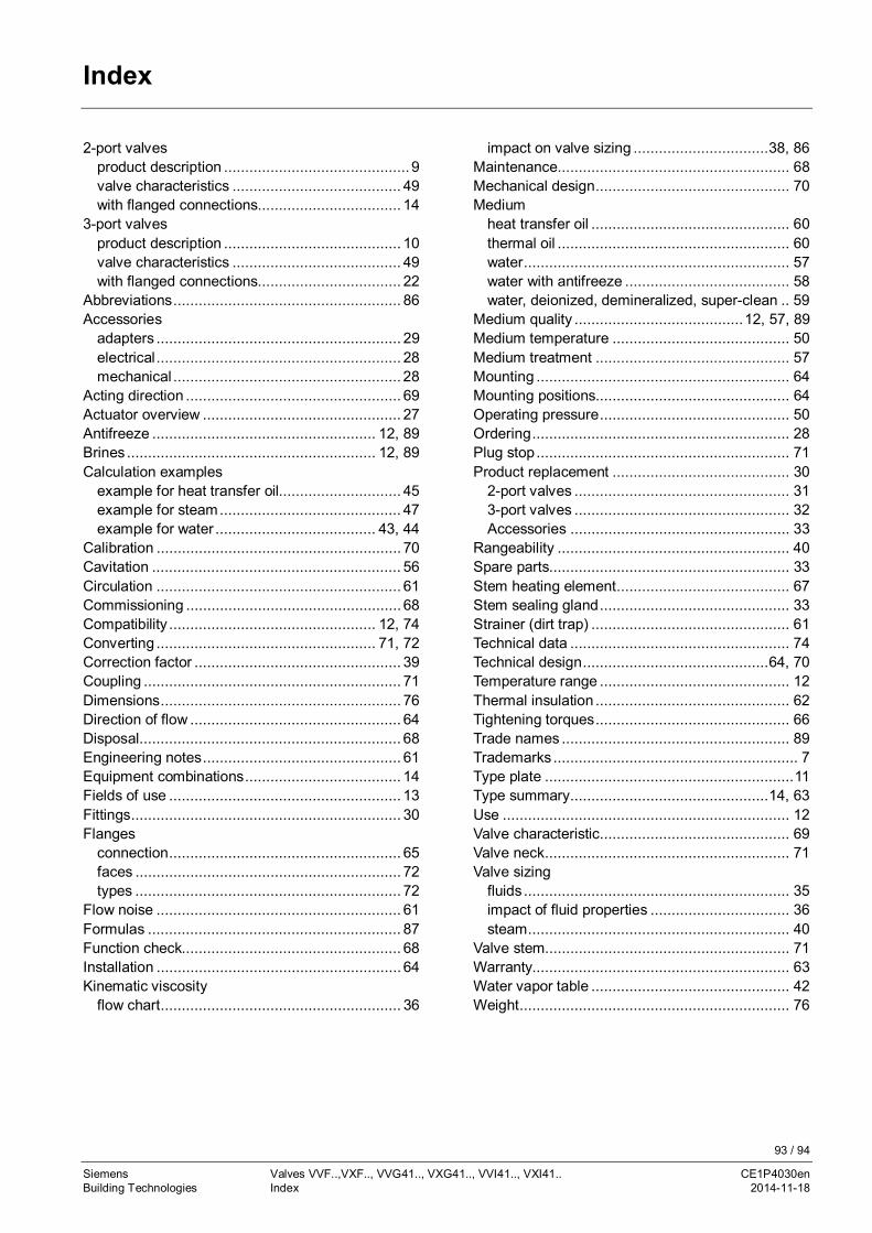
93 / 94
Siemens Valves VVF..,VXF.., VVG41.., VXG41.., VVI41.., VXI41.. CE1P4030enBuilding Technologies Index 2014-11-18
Index
2-port valvesproduct description ............................................ 9valve characteristics ........................................ 49with flanged connections.................................. 14
3-port valvesproduct description .......................................... 10valve characteristics ........................................ 49with flanged connections.................................. 22
Abbreviations ...................................................... 86Accessories
adapters .......................................................... 29electrical .......................................................... 28mechanical ...................................................... 28
Acting direction ................................................... 69Actuator overview ............................................... 27Antifreeze ..................................................... 12, 89Brines ........................................................... 12, 89Calculation examples
example for heat transfer oil............................. 45example for steam ........................................... 47example for water ...................................... 43, 44
Calibration .......................................................... 70Cavitation ........................................................... 56Circulation .......................................................... 61Commissioning ................................................... 68Compatibility ................................................. 12, 74Converting .................................................... 71, 72Correction factor ................................................. 39Coupling ............................................................. 71Dimensions ......................................................... 76Direction of flow .................................................. 64Disposal.............................................................. 68Engineering notes ............................................... 61Equipment combinations ..................................... 14Fields of use ....................................................... 13Fittings ................................................................ 30Flanges
connection ....................................................... 65faces ............................................................... 72types ............................................................... 72
Flow noise .......................................................... 61Formulas ............................................................ 87Function check.................................................... 68Installation .......................................................... 64Kinematic viscosity
flow chart ......................................................... 36
impact on valve sizing ................................ 38, 86Maintenance....................................................... 68Mechanical design .............................................. 70Medium
heat transfer oil ............................................... 60thermal oil ....................................................... 60water ............................................................... 57water with antifreeze ....................................... 58water, deionized, demineralized, super-clean .. 59
Medium quality ........................................ 12, 57, 89Medium temperature .......................................... 50Medium treatment .............................................. 57Mounting ............................................................ 64Mounting positions.............................................. 64Operating pressure ............................................. 50Ordering ............................................................. 28Plug stop ............................................................ 71Product replacement .......................................... 30
2-port valves ................................................... 313-port valves ................................................... 32Accessories .................................................... 33
Rangeability ....................................................... 40Spare parts......................................................... 33Stem heating element ......................................... 67Stem sealing gland ............................................. 33Strainer (dirt trap) ............................................... 61Technical data .................................................... 74Technical design ............................................ 64, 70Temperature range ............................................. 12Thermal insulation .............................................. 62Tightening torques .............................................. 66Trade names ...................................................... 89Trademarks .......................................................... 7Type plate ........................................................... 11Type summary ............................................... 14, 63Use .................................................................... 12Valve characteristic ............................................. 69Valve neck .......................................................... 71Valve sizing
fluids ............................................................... 35impact of fluid properties ................................. 36steam .............................................................. 40
Valve stem.......................................................... 71Warranty............................................................. 63Water vapor table ............................................... 42Weight ................................................................ 76

94 / 94
Siemens Valves VVF..,VXF.., VVG41.., VXG41.., VVI41.., VXI41.. CE1P4030enBuilding Technologies Index 2014-11-18
Siemens Switzerland Ltd.Building Technologies GroupInternational HeadquartersGubelstrasse 22CH-6301 ZugPhone +41 41-724 24 24Fax +41 41-724 35 22www.siemens.com/sbt
© Siemens Switzerland Ltd., 2011.Subject to change
