
acu
70
HP Array Configuration Utility User Guide September 2005 (Ninth Edition) Part Number 239449-009
Transcript of acu

HP Array Configuration Utility User Guide
September 2005 (Ninth Edition) Part Number 239449-009

© Copyright 2001, 2005 Hewlett-Packard Development Company, L.P.
The information contained herein is subject to change without notice. The only warranties for HP products and services are set forth in the express warranty statements accompanying such products and services. Nothing herein should be construed as constituting an additional warranty. HP shall not be liable for technical or editorial errors or omissions contained herein.
Microsoft, Windows, and Windows NT are U.S. registered trademarks of Microsoft Corporation. Java is a U.S. trademark of Sun Microsystems, Inc. Linux is a U.S. registered trademark of Linus Torvalds.
September 2005 (Ninth Edition)
Part Number 239449-009
Audience assumptions
This document is for the person who installs, administers, and troubleshoots servers and storage systems. HP assumes you are qualified in the servicing of computer equipment and trained in recognizing hazards in products with hazardous energy levels.

Contents 3
Contents Getting started.............................................................................................................................. 5
Features and system requirements................................................................................................................ 5 Installing ACU........................................................................................................................................... 5
Setting the execution mode for Microsoft Windows.............................................................................. 6 Overview for using ACU ............................................................................................................................ 6
Choosing an operating mode............................................................................................................ 7 Opening ACU in Local Application mode..................................................................................................... 7 Opening ACU in Browser mode.................................................................................................................. 8 Opening ACU through Systems Insight Manager ........................................................................................... 9 GUI operating modes .............................................................................................................................. 10
Typical Standard mode screen ........................................................................................................ 10 Typical Configuration Wizards mode screen..................................................................................... 11 Typical Express Configuration mode screen ...................................................................................... 12
Completing the configuration process ........................................................................................................ 12
Configuring a new controller........................................................................................................ 13 Using Standard Configuration mode.......................................................................................................... 13
Possible tasks in Standard Configuration mode.................................................................................. 13 Using Express Configuration mode ............................................................................................................ 14 Using the configuration wizards ................................................................................................................ 15
Creating an array.......................................................................................................................... 15 Creating a logical drive ................................................................................................................. 17
Modifying an existing configuration.............................................................................................. 19 Choices available after opening ACU........................................................................................................ 19 Modifying a configuration using Standard Configuration mode..................................................................... 19 Modifying a configuration using Express mode ........................................................................................... 20 Modifying a configuration using the Configuration wizards .......................................................................... 20
Clear Configuration ....................................................................................................................... 20 Controller settings.......................................................................................................................... 21 Create an array ............................................................................................................................ 21 Create a logical drive .................................................................................................................... 22 Delete arrays ................................................................................................................................ 23 Delete logical drives ...................................................................................................................... 24 Expand Array ............................................................................................................................... 24 Extend logical drive ....................................................................................................................... 25 Migrate a logical drive................................................................................................................... 25 Spare management ....................................................................................................................... 26 Selective Storage Presentation......................................................................................................... 26 Configuring switches...................................................................................................................... 28 Splitting a mirrored array ............................................................................................................... 29 Recombining a split, mirrored array ................................................................................................. 29
Scripting in ACU ........................................................................................................................ 31 Introduction to scripting in ACU................................................................................................................. 31 Operating modes .................................................................................................................................... 31 Command line syntax .............................................................................................................................. 31 Sample custom input script ....................................................................................................................... 32 Script file options .................................................................................................................................... 33
Description of option categories in ACU scripting .............................................................................. 33 Control category ........................................................................................................................... 34

Contents 4
Controller category........................................................................................................................ 34 Array category.............................................................................................................................. 36 Logical Drive category ................................................................................................................... 37
Error reporting ........................................................................................................................................ 39 ACU scripting error messages ......................................................................................................... 40
Using the Command Line Interface................................................................................................ 43 Overview of the ACU CLI ......................................................................................................................... 43
Running the CLI ............................................................................................................................. 43 CLI syntax..................................................................................................................................... 44 Keyword abbreviations .................................................................................................................. 44 Hiding warning prompts................................................................................................................. 45 Querying a device......................................................................................................................... 45 Help ............................................................................................................................................ 45
Typical procedures .................................................................................................................................. 45 Creating a logical drive ................................................................................................................. 46 Sample scenario............................................................................................................................ 46 Modifying the controller chassis name.............................................................................................. 47 Using Selective Storage Presentation ................................................................................................ 48 Deleting target devices ................................................................................................................... 50 Identifying devices ......................................................................................................................... 50 Expanding an array....................................................................................................................... 50 Extending a logical drive................................................................................................................ 50 Managing spare drives .................................................................................................................. 51 Migrating a logical drive................................................................................................................ 51 Changing the Rebuild Priority setting................................................................................................ 52 Changing the Expand Priority setting................................................................................................ 52 Changing the controller cache ratio ................................................................................................. 52 Changing the surface scan delay time.............................................................................................. 53 Re-enabling a failed logical drive .................................................................................................... 53 Enabling or disabling the drive cache .............................................................................................. 53 Enabling or disabling the array accelerator ...................................................................................... 54 Disabling a redundant controller...................................................................................................... 54 Setting the target ........................................................................................................................... 54 Rescanning the system.................................................................................................................... 55
Probability of logical drive failure ................................................................................................. 56 Factors involved in logical drive failure ...................................................................................................... 56
Probability of logical drive failure vs. number of drives in array........................................................... 57
Drive arrays and fault-tolerance methods ....................................................................................... 58 Drive arrays............................................................................................................................................ 58 Fault-tolerance methods............................................................................................................................ 60
Hardware-based fault-tolerance methods .......................................................................................... 60 Alternative fault-tolerance methods................................................................................................... 65
Diagnosing array problems.......................................................................................................... 66 Diagnostic tools ...................................................................................................................................... 66
Acronyms and abbreviations........................................................................................................ 67
Index......................................................................................................................................... 69

Getting started 5
Getting started
In this section Features and system requirements .............................................................................................................. 5 Installing ACU.......................................................................................................................................... 5 Overview for using ACU ........................................................................................................................... 6 Opening ACU in Local Application mode ................................................................................................... 7 Opening ACU in Browser mode................................................................................................................. 8 Opening ACU through Systems Insight Manager ......................................................................................... 9 GUI operating modes ............................................................................................................................. 10 Completing the configuration process ....................................................................................................... 12
Features and system requirements The HP Array Configuration Utility (ACU) is a browser-based utility that: • Can be used online (that is, while the operating system is running) • Has different operating modes, enabling faster configuration or greater control over the
configuration options • Suggests the optimum configuration for an unconfigured system • Provides on-screen tips for individual steps of a configuration procedure • Enables online array capacity expansion, logical drive capacity extension, assignment of online
spares, and RAID or stripe size migration
The minimum display settings for optimum performance are 1024 x 768 pixels resolution and 256 colors. Refer to the README.TXT file for further information about browser and operating system support.
Installing ACU Download ACU from the HP website or from the CD that is supplied with the controller, and then install it onto the server.

Getting started 6
Setting the execution mode for Microsoft Windows During the installation process on a server using a supported Microsoft® Windows® operating system, you are prompted to select the Execution Mode setting. This setting determines whether you can run ACU on the server from a remote network location.
You can change the execution mode at any time by selecting Setup HP Array Configuration Utility from the Start menu.
Comparison of ACU execution modes
Local Application mode Remote Service mode
ACU is installed as an executable application.
ACU is installed as a service that starts when the server is powered up.
ACU runs only on the local system and cannot be run remotely.
A browser is used to render the user interface, but no Web server is required.
ACU can be run remotely from another server across a network.
Authentication is handled by the operating system, ensuring that the user is an administrator on the server running ACU.
Authentication is handled through the same mechanism used for Systems Insight Manager agents.
Overview for using ACU 1. Open ACU.
You can operate ACU in scripting mode ("Scripting in ACU" on page 31), CLI mode ("Using the Command Line Interface" on page 43), or GUI mode. Furthermore, you can access the GUI mode in the following ways: • As a local application (this method is available only on Microsoft® Windows® platforms)
("Opening ACU in Local Application mode" on page 7) • Through a browser ("Opening ACU in Browser mode" on page 8) • Through HP Systems Insight Manager ("Opening ACU through Systems Insight Manager" on
page 9)

Getting started 7
NOTE: Some advanced tasks are not available in all operating modes. For further information, refer to "Tasks possible in each operating mode ("Choosing an operating mode" on page 7)."
2. If you opened ACU in GUI mode: a. Select the controller that you want to configure. b. Select the configuration mode that you want to use ("GUI operating modes" on page 10).
3. Configure the controller. • If you are using scripting ("Scripting in ACU" on page 31) or the CLI ("Using the Command
Line Interface" on page 43), refer to the appropriate chapter for further details. • If you are using a GUI method to configure a new controller, refer to "Configuring a New
Controller (on page 13)" for further details. • If you are using a GUI method to modify an existing configuration, refer to "Modifying an
Existing Configuration (on page 19)" for further details. 4. If using a GUI, save the configuration changes. 5. Select another controller to configure, or exit ACU. 6. To make newly created logical drives available for data storage, use the operating system disk
management tools to create partitions and format the drives.
Choosing an operating mode Some advanced tasks can be performed only when using a particular operating mode (GUI, CLI, or scripting).
NOTE: A + in the appropriate column indicates that the feature or procedure is supported, while -- indicates that the feature or procedure is not supported.
Task GUI CLI Scripting
Basic configuration or reconfiguration of drives and arrays (create or modify logical drives, change controller settings, set cache ratio)
+ + +
Configure several systems identically +* +* +
Configure SSP + + +
Configure switches + -- --
Copy the configuration of one system to several other systems
-- -- +
Disable a redundant controller -- + --
Enable or disable hard drive write cache -- + --
Identify devices by causing their LEDs to blink + + --
Re-enable a failed logical drive -- + --
Set the surface scan delay + + +
Split a RAID 1 array, or recombine a split array
+ -- --
*Scripting is more efficient for this task.
Opening ACU in Local Application mode 1. Click Start, and navigate to Programs>HP System Tools>HP Array Configuration
Utility.

Getting started 8
The browser opens and launches ACU, which then identifies the controllers that are connected to the system. This process could take a minute or two.
2. When controller detection is complete, select a controller from the list on the left side of the screen. The main ACU configuration screen appears.
Opening ACU in Browser mode 1. Open ACU on the host. 2. If you intend to configure a remote server, confirm that the ACU Execution mode is set to Remote
service ("Setting the execution mode for Microsoft Windows" on page 6). 3. Open the browser, either locally (on the host) or on the remote server. 4. Enter the following text into the browser address field (where servername is the name or IP address
of the host): http://servername:2301
The login screen for the System Management Homepage opens. 5. Log in.
• If you are using version 2.0.0 or newer of the System Management Homepage, use your operating system user name and password.
• If you are using an older version of the System Management Homepage, use your WBEM user name and password.
For further information, refer to the HP System Management Homepage (http://h18013.www1.hp.com/products/servers/management/agents/index.html) or the HP System Management Homepage Installation Guide available on the HP website (http://www.hp.com). The System Management Homepage opens.
6. Click Array Configuration Utility on the left side of the screen. ACU opens and identifies the controllers that are connected to the system. This process could take a minute or two.
7. When controller detection is complete, select a controller from the list on the left side of the screen.

Getting started 9
The main ACU configuration screen appears.
Opening ACU through Systems Insight Manager 1. On the server that has ACU loaded, confirm that the utility is running in Remote Service mode
("Setting the execution mode for Microsoft Windows" on page 6). 2. On the remote server, connect to the Systems Insight Manager server (port :280), and log in. 3. Select Device Queries. 4. Under Device by Type, select All Servers. 5. Connect to the server that is running ACU. 6. Under Device Links, select System Management Homepage.
The login screen for the System Management Homepage opens. 7. Log in.
• If you are using version 2.0.0 or newer of the System Management Homepage, use your operating system user name and password.
• If you are using an older version of the System Management Homepage, use your WBEM user name and password.
For further information, refer to the HP System Management Homepage (http://h18013.www1.hp.com/products/servers/management/agents/index.html) or the HP System Management Homepage Installation Guide available on the HP website (http://www.hp.com) The System Management Homepage opens.
8. Click Array Configuration Utility on the left side of the screen. ACU opens and identifies the controllers that are connected to the system. This process could take a minute or two.
9. When controller detection is complete, select a controller from the list on the left side of the screen.

Getting started 10
The main ACU configuration screen appears.
GUI operating modes The GUI format of ACU has three configuration modes: • Standard mode ("Typical Standard mode screen" on page 10) enables you to manually configure all
options on the controller. • Configuration Wizards mode ("Typical Configuration Wizards mode screen" on page 11) guides
you through each step of a manual configuration process. • Express Configuration mode ("Typical Express Configuration mode screen" on page 12)
automatically sets up the controller configuration based on your answers to a few simple questions.
Standard mode is the default setting. If you are unfamiliar with ACU, change to Configuration Wizards mode (or to Express Configuration mode, if it is available for that particular array). You can access these alternative modes by clicking the appropriate link in the lower right-hand corner of the main ACU configuration screen.
Typical Standard mode screen
This is the default configuration mode for ACU. All the configuration options for a selected item in the Configuration View panel appear in a frame on the right side of the screen.

Getting started 11
Typical Configuration Wizards mode screen
The Configuration Wizards mode screen consists of four regions: the Devices list, the Configuration View panel, the Main Menu, and the FAQ column. • The Devices list on the left side of the screen shows all the identifiable controllers that are connected
to the system. • The gray Configuration View panel in the upper central portion of the screen shows all arrays,
logical drives, unused space, and unassigned physical drives that are connected to the selected controller. The logical configuration view is shown by default. • To view the physical configuration, click Show Physical View in the upper right corner of
the panel. • To get further information about any item in this panel, click the icon for the item. A window
appears.
• The Main Menu in the lower central portion of the screen shows the allowable options at this stage. • The FAQ column on the right side of the screen lists information and tips that are relevant to the
current screen. Look at this region before clicking Help in the upper right corner of the browser screen.

Getting started 12
Typical Express Configuration mode screen
NOTE: Express mode is listed as a configuration option only if the controller that you select has unused space on an array or physical drives that are not assigned to an array.
Express Configuration mode screens are similar in appearance to Configuration Wizards mode screens ("Typical Configuration Wizards mode screen" on page 11), but the directive text is different. In Express Configuration mode, ACU asks you a few simple questions about your configuration preferences and then automatically sets up the optimum configuration based on your answers.
Completing the configuration process Details of the subsequent steps in the configuration process are given in the remainder of this guide. • If the controller is not configured (it has no arrays or logical drives, only unassigned physical drives),
refer to “Configuring a new controller (on page 13).” • If the controller is already configured but you want to reconfigure it, refer to “Modifying an existing
configuration (on page 19).”
Configuring a new controller 13
Configuring a new controller
In this section Using Standard Configuration mode......................................................................................................... 13 Using Express Configuration mode........................................................................................................... 14 Using the configuration wizards............................................................................................................... 15
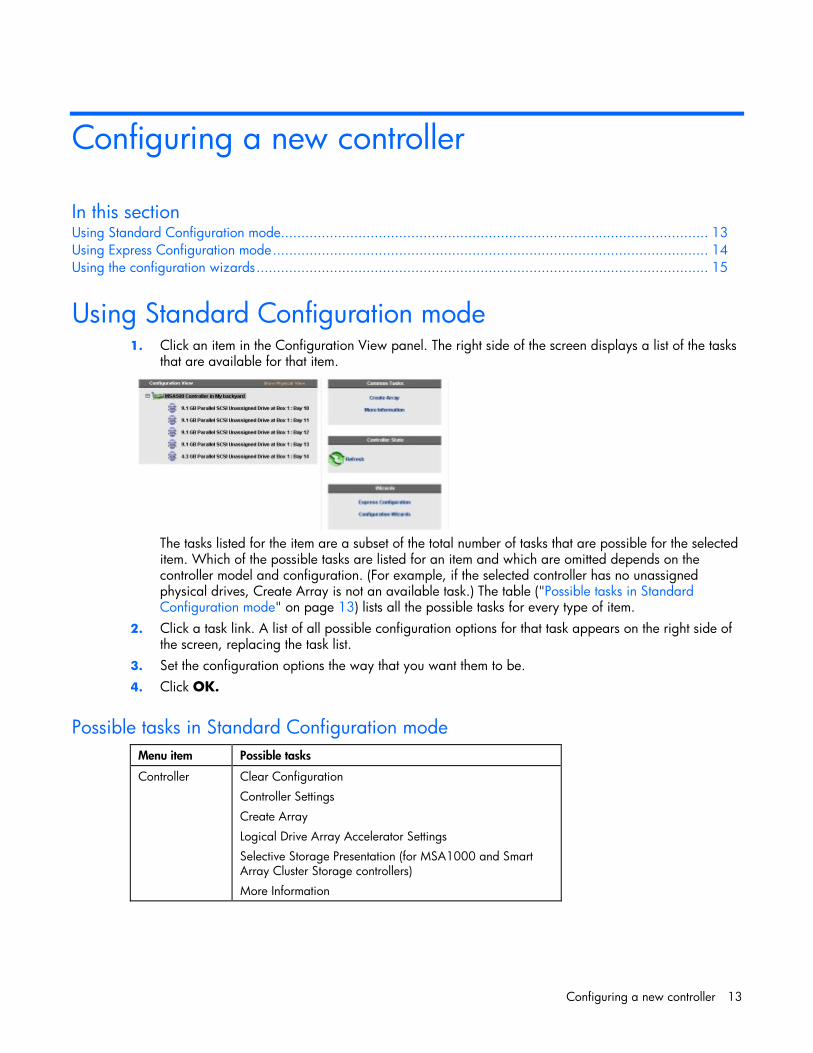
Using Standard Configuration mode 1. Click an item in the Configuration View panel. The right side of the screen displays a list of the tasks
that are available for that item.
The tasks listed for the item are a subset of the total number of tasks that are possible for the selected item. Which of the possible tasks are listed for an item and which are omitted depends on the controller model and configuration. (For example, if the selected controller has no unassigned physical drives, Create Array is not an available task.) The table ("Possible tasks in Standard Configuration mode" on page 13) lists all the possible tasks for every type of item.
2. Click a task link. A list of all possible configuration options for that task appears on the right side of the screen, replacing the task list.
3. Set the configuration options the way that you want them to be. 4. Click OK.
Possible tasks in Standard Configuration mode
Menu item Possible tasks
Controller Clear Configuration
Controller Settings
Create Array
Logical Drive Array Accelerator Settings
Selective Storage Presentation (for MSA1000 and Smart Array Cluster Storage controllers)
More Information

Configuring a new controller 14
Menu item Possible tasks
Array Assign Spare
Create Logical Drive
Delete
Expand
Re-Mirror Array
Remove Spare
Split Mirrored Array
More Information
Logical drive Delete
Extend Size
Migrate RAID/Stripe Size
Selective Storage Presentation (for RA4x00 controllers)
More Information
Unused space Create Logical Drive
More Information
Using Express Configuration mode 1. Click Express Configuration in the lower right panel of the main ACU configuration screen. The
Express mode start screen appears.
2. Click Begin.
ACU creates the optimum number of arrays and logical drives from all of the physical drives that are attached to the controller. This process takes a few moments. When it is finished, the screen is updated. The gray Configuration View panel shows the new configuration, and underneath this panel is a list of possible fault-tolerance levels for the first logical drive.

Configuring a new controller 15
3. Select a RAID level, and then click Next. 4. If you select a fault-tolerant RAID method and an unassigned physical drive of the appropriate
capacity is available, ACU asks if you want to assign spare drives to the array. • If you do not want this array to have a spare, click No, and then click Next. • To assign spares to the array, click Yes, and then click Next. On the next screen, select the
drives that you want to be the spares, and then click Next.
IMPORTANT: Assigning one or more spare drives to an array enables you to postpone replacement of faulty drives, but it does not increase the fault-tolerance level of any logical drives in the array. For example, a logical drive in a RAID 5 configuration suffers irretrievable data loss if two physical drives fail simultaneously, regardless of the number of spare drives assigned to it.
The panel displays the new configuration and asks you to confirm that it is acceptable. • If you discard the configuration, you are returned to the main ACU configuration screen so that
you can manually configure the new array. • If you accept the configuration, the next screen displays confirmation that ACU has saved the
new configuration. At this point, you can refine the configuration using one of the other modes, configure another controller, or exit ACU.
5. Select the appropriate radio button to accept or discard the configuration. 6. Click Finish.
Using the configuration wizards When using the wizards, you first create at least one array ("Creating an array" on page 15), and then you populate the array with logical drives ("Creating a logical drive" on page 17).
Creating an array 1. Click Configuration Wizards in the lower right panel of the main ACU configuration screen. 2. Click Create an array, and then click Begin.

Configuring a new controller 16
The Configuration View panel displays a placeholder for the array that you are about to create. (If there are many physical drives connected to the controller, use the scrollbars in the Configuration View panel to see all the physical drives and arrays.)
3. Select the type of drive that you will use in the array. 4. Select the physical drives that you want to use in the array.
• Use physical drives of comparable capacity. ACU uses the same amount of space from each physical drive to build an array. Because this amount cannot exceed the capacity of the smallest physical drive, the extra capacity of any larger drive in the array is unusable.
• For better system performance, use physical drives that are connected to different ports on the controller.
• In RAID 5 configurations, keep the risk of logical drive failure low by assigning no more than 14 physical drives to the array.
Each time that you add a physical drive to the array, the configuration view is updated to show how much free space remains on the array.
5. Click Next when you have finished adding physical drives to the array. 6. If an unassigned physical drive of the appropriate capacity is available, ACU asks you whether you
want to assign spare drives to the array. • If you do not want this array to have a spare, click No, and then click Next. • To assign spare drives to the array, click Yes, and then click Next. On the next screen, select
the drives that you want to be the spares, and then click Next.
IMPORTANT: Assigning one or more spare drives to an array enables you to postpone replacement of faulty drives, but it does not increase the fault-tolerance level of any logical drives in the array. For example, a logical drive in a RAID 5 configuration suffers irretrievable data loss if two physical drives fail simultaneously, regardless of the number of spare drives assigned to it.

Configuring a new controller 17
7. Click Finish to confirm the configuration. The drives are now configured as unused space on the new array.
To create more arrays on the same controller, repeat the previous steps.
Creating a logical drive 1. Click Create a logical drive, and then click Begin. 2. Select an array that has unused space, and then click Next. (The array must have unused space for
logical drive creation to be possible.) The screen displays a list of the fault-tolerance levels that are possible for this configuration. For example, RAID 5 is not listed if the array has only two physical drives.
3. Select a fault-tolerance level, and then click Next. 4. Select a stripe size, and then click Next.
The default stripe size gives optimum performance in a mixed read/write environment. If your system is used in a different environment, refer to the following table to determine what stripe size to set.
Type of server application Suggested stripe size change
Mixed read/write Accept the default value.
Mainly sequential read (such as audio/video applications)
Use a larger stripe size.
Mainly write (such as image manipulation applications)
Use a smaller stripe size for RAID 5 or RAID 6 (ADG).
Use a larger stripe size for RAID 0 or RAID 1+0.
*Not all controllers support RAID 6 (ADG).
The next screen gives you the option to enable MaxBoot. When MaxBoot is enabled, 63 sectors are used per track instead of 32. This increased number of sectors allows a larger boot partition for operating systems such as Microsoft® Windows NT® 4.0 that use cylinders, heads, and sectors of a physical drive to determine the drive size. It also enables you to create a larger logical drive or increase the logical drive size (extend it) at a later time. Logical drive performance is likely to decrease with MaxBoot enabled.
5. Decide whether to use MaxBoot, and then click Next. The next screen enables you to set the size of the logical drive. The default size shown is the largest possible logical drive size for the RAID level that you chose and the set of physical drives that is being used. Reducing the size of the logical drive liberates drive space, which you can use to build additional logical drives on the same array.

Configuring a new controller 18
6. Set the size that you want the logical drive to be, and then click Next. If the controller has an array accelerator, a screen appears that gives you the option of disabling it for the currently selected logical drive.
NOTE: Disabling the array accelerator for a logical drive reserves use of the accelerator cache for other logical drives on the array. This feature is useful if you want the other logical drives to have the maximum possible performance (for example, if the logical drives contain database information).
7. Select the option that you want, and then click Next. The gray Configuration View panel shows the configuration that you have chosen.
8. Verify that the configuration is acceptable, and then click Finish.
9. Click the Save icon to commit the changes to the controller, and then click OK on the confirmation
alert. (If you click Discard Changes, all changes since the previous save are lost.) 10. To make newly created logical drives available for data storage, use the operating system disk
management tools to create partitions and format the drives.

Modifying an existing configuration 19
Modifying an existing configuration
In this section Choices available after opening ACU....................................................................................................... 19 Modifying a configuration using Standard Configuration mode ................................................................... 19 Modifying a configuration using Express mode.......................................................................................... 20 Modifying a configuration using the Configuration wizards......................................................................... 20
Choices available after opening ACU Open ACU as described in "Getting started (on page 5)," and select a controller.
At this point, you can continue operating in Standard mode, or you can select a wizard from the lower right-hand panel. If the controller that you selected is an MSA1000, another link in this panel leads to a screen that enables you to configure switches.
Modifying a configuration using Standard Configuration mode
1. Click an item in the Configuration View panel. The right side of the screen displays a list of the tasks that are available for that item.
The tasks listed for the item are a subset of the total number of tasks that are possible for the selected item. Which of the possible tasks are listed for an item and which are omitted depends on the controller model and configuration. (For example, if the selected controller has no unassigned physical drives, Create Array is not an available task.) The table ("Possible tasks in Standard Configuration mode" on page 13) lists all the possible tasks for every type of item.
2. Click a task link. A list of all possible configuration options for that task appears on the right side of the screen, replacing the task list.
3. Set the configuration options the way that you want them to be. 4. Click OK.

Modifying an existing configuration 20
Modifying a configuration using Express mode NOTE: Express mode is listed as a configuration option only if the controller that you select has unused
space on an array or physical drives that are not assigned to an array.
1. Click Express Configuration, and then click Begin. If there are unassigned physical drives on the controller, you can create a new array or expand an existing array. Make your choice, and then click Next.
IMPORTANT: An array expansion, logical drive extension, or logical drive migration takes about 15 minutes per gigabyte, or considerably longer if the controller does not have a battery-backed cache. While this process is occurring, no other expansion, extension, or migration can occur simultaneously on the same controller.
The screen displays the optimum configuration for the controller and asks you to confirm that it is acceptable.
2. Select the appropriate radio button, and then click Finish.
Modifying a configuration using the Configuration wizards The options listed in the menu region of the screen depend on the controller model and configuration. For example, the Expand array option is listed only if there is at least one unassigned physical drive connected to the controller.
The possible menu options are: • Clear configuration (on page 20) • Controller settings (on page 21) • Create an array (on page 21) • Create a logical drive (on page 22) • Delete arrays (on page 23) • Delete logical drives (on page 24) • Expand array (on page 24) • Extend logical drive (on page 25) • Migrate a logical drive (on page 25) • Spare management (on page 26) • Selective storage presentation (on page 26)
Clear Configuration The Clear Configuration task deletes all logical drives connected to the controller, reconfigures the arrays into independent (unassigned) physical drives, and resets all controller settings to their default values. 1. Click Clear Configuration, and then click Begin.
ACU displays a warning screen to remind you that you will lose all data on the logical drive. 2. Click Delete to continue. 3. Click Finish to accept the changes. 4. Click Save to apply the changes to the system, and then click OK on the confirmation alert.
The physical drives are now available for reconfiguration.

Modifying an existing configuration 21
Controller settings The default controller settings that ACU provides are adequate for many purposes. When necessary, however, you can use the Controller Settings task to: • Alter the priority that the system gives to an array expansion or rebuild • Disable the array accelerator (if one is present) • Change the ratio of read cache to write cache (if the controller has battery-backed cache)
To change the controller settings: 1. Click Controller Settings, and then click Begin.
The next two screens enable you to change the settings for the expand priority and the rebuild priority. These settings determine how much importance you want an array expansion or rebuild to have relative to normal I/O operations. • With low priority, the expansion or rebuild takes place only when the array controller is not
busy handling normal I/O requests. This setting has minimal effect on normal I/O operations. However, there is an increased risk that data will be lost if another physical drive fails while the rebuild or expansion is in progress.
• With high priority, the rebuild or expansion occurs at the expense of normal I/O operations. Although system performance is affected, this setting provides better data protection because the array is vulnerable to additional drive failures for a shorter time.
• At the medium priority setting, expansion or rebuild occurs for half of the time, and normal I/O requests are handled during the rest of the time.
2. Set the expand priority to high, medium, or low, and then click Next. 3. Set the rebuild priority, and then click Next.
If the controller has an array accelerator, a screen now appears that gives you the option of disabling it for particular logical drives.
NOTE: Disabling the array accelerator for a logical drive reserves use of the accelerator cache for other logical drives on the array. This feature is useful if you want the other logical drives to have the maximum possible performance (for example, if the logical drives contain database information).
4. Select the logical drives for which the array accelerator should be disabled, and then click Next. If the controller has a battery-backed cache, a screen now appears that enables you to change the read/write cache ratio. This ratio determines the amount of memory allocated to read and write operations. Different types of applications have different optimum ratios. You can change the ratio only if the controller has a battery-backed cache (only battery-backed cache can be used for write cache) and if there are logical drives configured on the controller.
5. Select the ratio that you want the controller to use, and then click Next. 6. Click Finish to accept the changes. 7. Click Save to apply the changes to the system, and then click OK on the confirmation alert.
Create an array 1. Click Create an array, and then click Begin. 2. Select the type of drive to be used in the array. 3. Select the physical drives that you want to use in the array.
• Use physical drives of comparable capacity. ACU uses the same amount of space from each physical drive to build an array. Because this amount cannot exceed the capacity of the smallest physical drive, the extra capacity of any larger drive in the array is unusable.

Modifying an existing configuration 22
• For better system performance, use physical drives that are attached to different ports on the controller.
• In RAID 5 configurations, keep the risk of logical drive failure low by assigning no more than 14 physical drives to the array.
Each time that you add a physical drive to the array, the configuration view is updated to show how much free space remains on the array.
4. Click Next when you have finished adding physical drives to the array. 5. If a spare or unassigned physical drive of the appropriate capacity is available, ACU asks you
whether you want to assign a spare drive to the array. • If you do not want this array to have a spare, click No, and then click Next. • To assign spare drives to the array, click Yes, and then click Next. On the next screen, select
the drives that you want to assign as spares, and then click Next.
IMPORTANT: Assigning one or more spare drives to an array enables you to postpone replacement of faulty drives, but it does not increase the fault-tolerance level of any logical drives in the array. For example, a logical drive in a RAID 5 configuration suffers irretrievable data loss if two physical drives fail simultaneously, regardless of the number of spare drives assigned to it.
NOTE: An array can have several spares, and any spare can be shared by several arrays.
6. Click through the remaining screens to confirm the configuration.
Create a logical drive 1. Click Create a logical drive, and then click Begin. 2. Select an array that has unused space, and then click Next. (The array must have unused space for
logical drive creation to be possible.) The screen displays a list of the fault-tolerance levels that are possible for this configuration. For example, RAID 5 is not listed if the array has only two physical drives.
3. Select a fault-tolerance level, and then click Next. 4. Select a stripe size, and then click Next.
The default stripe size gives optimum performance in a mixed read/write environment. If your system is used in a different environment, refer to the following table to determine what stripe size to set.
Type of server application Suggested stripe size change
Mixed read/write Accept the default value.
Mainly sequential read (such as audio/video applications)
Use a larger stripe size.
Mainly write (such as image manipulation applications)
Use a smaller stripe size for RAID 5 or RAID 6 (ADG).
Use a larger stripe size for RAID 0 or RAID 1+0.
*Not all controllers support RAID 6 (ADG).
The next screen gives you the option to enable MaxBoot. When MaxBoot is enabled, 63 sectors are used per track instead of 32. This increased number of sectors allows a larger boot partition for operating systems such as Microsoft® Windows NT® 4.0 that use cylinders, heads, and sectors of a physical drive to determine the drive size. It also enables you to create a larger logical drive or increase the logical drive size (extend it) at a later time. Logical drive performance is likely to decrease with MaxBoot enabled.
5. Decide whether to use MaxBoot, and then click Next.

Modifying an existing configuration 23
The next screen enables you to set the size of the logical drive. The default size shown is the largest possible logical drive size for the RAID level that you chose and the set of physical drives that is being used. Reducing the size of the logical drive liberates drive space, which you can use to build additional logical drives on the same array.
6. Set the size that you want the logical drive to be, and then click Next. If the controller has an array accelerator, a screen appears that gives you the option of disabling it for the currently selected logical drive.
NOTE: Disabling the array accelerator for a logical drive reserves use of the accelerator cache for other logical drives on the array. This feature is useful if you want the other logical drives to have the maximum possible performance (for example, if the logical drives contain database information).
7. Select the option that you want, and then click Next. The gray Configuration View panel shows the configuration that you have chosen.
8. Verify that the configuration is acceptable, and then click Finish.
9. Click the Save icon to commit the changes to the controller, and then click OK on the confirmation
alert. (If you click Discard Changes, all changes since the previous save are lost.) 10. To make newly created logical drives available for data storage, use the operating system disk
management tools to create partitions and format the drives.
Delete arrays This task deletes logical drives on an array and converts the array into a group of unassigned physical drives. You can then reconfigure the unassigned physical drives into one or more new arrays ("Create an array" on page 21), or you can use the liberated physical drive space for expansion of another array ("Expand Array" on page 24) on the same controller. 1. Click Delete arrays, and then click Begin. 2. Select the arrays that you want to delete, and then click Next. ACU displays a warning screen to
remind you that you will lose all data on the array. 3. Click Delete to continue, and then click Finish to accept the changes. 4. Click Save to apply the changes to the system, and then click OK on the confirmation alert.

Modifying an existing configuration 24
Delete logical drives This task deletes the selected logical drive and converts it into unused drive space. You can then use this unused drive space to: • Create new logical drives ("Create a logical drive" on page 22). • Migrate the RAID level or stripe size of an existing logical drive ("Migrate a logical drive" on page
25). • Extend existing logical drives on the same array ("Extend logical drive" on page 25), if the
operating system allows logical drive extension.
To delete a logical drive: 1. Click Delete logical drives, and then click Begin. 2. Select the logical drives that you want to delete, and then click Next. ACU displays a warning
screen to remind you that you will lose all data on the logical drive. 3. Click Delete to continue, and then click Finish to accept the changes. 4. Click Save to apply the changes to the system, and then click OK on the confirmation alert.
Expand Array
NOTE: The Expand Array task is listed only if there is an unassigned physical drive on the controller. The unassigned drive must also have a capacity no less than that of a drive in an existing array. If these conditions are not fulfilled, install at least one suitable drive on the controller, and then click Refresh.
This task increases the storage capacity of an existing array. You can use the additional storage space to: • Create new logical drives ("Create a logical drive" on page 22). • Migrate the RAID level or stripe size of existing logical drives ("Migrate a logical drive" on page
25). • Extend existing logical drives on the array ("Extend logical drive" on page 25), if the operating
system allows logical drive extension.
IMPORTANT: An array expansion, logical drive extension, or logical drive migration takes about 15 minutes per gigabyte, or considerably longer if the controller does not have a battery-backed cache. While this process is occurring, no other expansion, extension, or migration can occur simultaneously on the same controller.
1. Click Controller Settings, and verify that the Expand Priority setting is acceptable. 2. Back up all data on the array. Although array expansion is unlikely to cause data loss, observing
this precaution provides additional data protection. 3. Click Expand array, and then click Begin. 4. Choose the array that you want to expand, and then click Next. 5. Select the physical drives that you want to add to the array, and then click Next. 6. Click Finish to accept the changes.
At this point (before clicking Save in the next step), you can create logical drives on the unused space created by the expansion. You can also arrange to expand another array on the same controller by repeating the previous steps. However, the controller can expand only one array at a time. Remaining array expansions are queued.
7. Click Save. The controller now rearranges (re-stripes) the existing logical drives and their data so that they extend over all the physical drives in the enlarged array.

Modifying an existing configuration 25
To check the progress of an array expansion, click the icon for that array in the Configuration View panel. A More Information pop-up window opens that describes the array status.
Extend logical drive This option increases the storage capacity of a logical drive by adding unused space on an array to a logical drive on the same array. The unused space is obtained either by expanding an array ("Expand Array" on page 24) or by deleting another logical drive ("Delete logical drives" on page 24) on the same array.
Not all operating systems support online logical drive extension through ACU.
Some operating systems allow you to perform logical drive extension offline by backing up data, reconfiguring the array, and restoring data from backup. Check the operating system documentation for current information.
IMPORTANT: An array expansion, logical drive extension, or logical drive migration takes about 15 minutes per gigabyte, or considerably longer if the controller does not have a battery-backed cache. While this process is occurring, no other expansion, extension, or migration can occur simultaneously on the same controller.
1. Back up all data on the logical drive. Although logical drive extension is unlikely to cause data loss, observing this precaution provides additional data protection.
2. Click Extend logical drive, and then click Begin. 3. Select the logical drive that you want to extend, and then click Next. 4. Enter the new size of the logical drive into the size field. 5. Click Finish.
At this point (before clicking Save in the next step), you can arrange to extend another logical drive on the same controller by repeating the previous steps. However, the controller can extend only one logical drive at a time. Remaining extensions are queued.
6. Click Save. Logical drive extension begins.
To check the progress of a logical drive extension, click the icon for that logical drive in the Configuration View panel. A More Information pop-up window opens that describes the logical drive status.
Migrate a logical drive This option enables you to alter the stripe size (data block size), RAID level, or both for a selected logical drive. For some combinations of initial and final settings of stripe size and RAID level, the array must contain unused drive space.
IMPORTANT: An array expansion, logical drive extension, or logical drive migration takes about 15 minutes per gigabyte, or considerably longer if the controller does not have a battery-backed cache. While this process is occurring, no other expansion, extension, or migration can occur simultaneously on the same controller.
1. Back up all data on the logical drive. Although migration is unlikely to cause data loss, observing this precaution provides additional data protection.
2. Click Migrate a logical drive, and then click Begin. 3. Select the logical drive, and then click Next. 4. Select the new RAID level, and then click Next.
Only RAID levels that are possible for this configuration are shown. For example, RAID 5 is not listed if the array has only two physical drives.
5. Select the stripe size. Only stripe sizes that are possible for this configuration are shown.

Modifying an existing configuration 26
6. Click Finish to accept the changes. At this point (before clicking Save in the next step), you can arrange to migrate another logical drive on the same controller by repeating the previous steps. However, the controller can migrate only one logical drive at a time. Remaining migrations are queued.
7. Click Save. Migration begins.
To check the progress of a migration, click the icon for that logical drive in the Configuration View panel. A More Information pop-up window opens that describes the logical drive status.
Spare management
NOTE: An array can have several spares, and any spare can be shared by several arrays. 1. Click Spare Management, and then click Begin. 2. Select the array that is to have additional (or fewer) spare drives. 3. Select the drives that you want to assign as spares, and deselect the appropriate checkboxes for
spares that you want to remove.
IMPORTANT: Assigning one or more spare drives to an array enables you to postpone replacement of faulty drives, but it does not increase the fault-tolerance level of any logical drives in the array. For example, a logical drive in a RAID 5 configuration suffers irretrievable data loss if two physical drives fail simultaneously, regardless of the number of spare drives assigned to it.
4. Click Next. 5. Click Finish to accept the changes. 6. Click Save, and then click OK on the confirmation alert.
Selective Storage Presentation SSP enables you to determine which host controllers can access which particular logical drives in a storage system. This feature prevents data corruption that can occur when different servers using different operating systems access the same data.
SSP is available only for RA4x00 controllers, Smart Array Cluster Storage controllers, and some MSA controllers. To confirm that a particular MSA storage system supports SSP, refer to the user guide for that system.
RA4x00 controllers 1. Click Selective Storage Presentation, and then click Begin. 2. Select the logical drive for which you want to change the access settings, and then click Next. 3. On the next screen that appears, select the appropriate radio button to enable or disable SSP and
then click Next. • If you disable SSP, all host controllers have access to the logical drive. • If you enable SSP, you can decide which hosts are to have access to the logical drive. If you selected Enable, the screen lists all identified host controllers.
4. Select the host controllers that are to have access to the logical drive, rename the connections if necessary, and then click Next.

Modifying an existing configuration 27
NOTE: Be sure that every HBA in the system has access to the logical drives for which multi-path will be used.
5. Click Finish.
MSA and Smart Array Cluster storage controllers 1. Click Selective Storage Presentation, and then click Begin.
On the next screen that appears, select the appropriate radio button to enable or disable SSP, and then click Next. • If you disable SSP, all host controllers have access to all logical drives. • If you enable SSP, you can decide which hosts are to have access to which logical drives. If you select Enable, the screen lists all identified host controllers.
2. Select the host controllers that are to have access to each logical drive, define the host mode for each controller, rename the connections if necessary, and then click Next.
NOTE: Be sure that every HBA in the system has access to the logical drives for which multi-path will be used.
3. Click Finish.

Modifying an existing configuration 28
Configuring switches If the selected controller supports switch configuration, the menu link for this feature is given in the Wizards panel in the lower right-hand corner of the main ACU configuration screen. 1. Use the PING command to confirm that the connections between the management server running
ACU and the LAN management ports on the switches are reliable. 2. Click Switch Configuration (in the Wizards panel). 3. Select the switch that you want to configure, and then click Next.
4. Click ACU Switch Configuration.
5. Set the switch parameters (IP address, default gateway, subnet mask, and community strings), and
then click Finish to save the settings.
Modifying an existing configuration 29
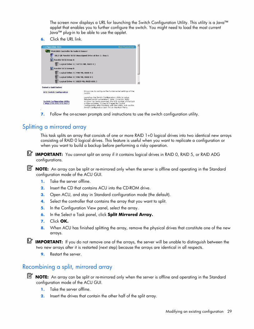
The screen now displays a URL for launching the Switch Configuration Utility. This utility is a Java™ applet that enables you to further configure the switch. You might need to load the most current Java™ plug-in to be able to use the applet.
6. Click the URL link.
7. Follow the on-screen prompts and instructions to use the switch configuration utility.
Splitting a mirrored array This task splits an array that consists of one or more RAID 1+0 logical drives into two identical new arrays consisting of RAID 0 logical drives. This feature is useful when you want to replicate a configuration or when you want to build a backup before performing a risky operation.
IMPORTANT: You cannot split an array if it contains logical drives in RAID 0, RAID 5, or RAID ADG configurations.
NOTE: An array can be split or re-mirrored only when the server is offline and operating in the Standard configuration mode of the ACU GUI.
1. Take the server offline. 2. Insert the CD that contains ACU into the CD-ROM drive. 3. Open ACU, and stay in Standard configuration mode (the default). 4. Select the controller that contains the array that you want to split. 5. In the Configuration View panel, select the array. 6. In the Select a Task panel, click Split Mirrored Array. 7. Click OK. 8. When ACU has finished splitting the array, remove the physical drives that constitute one of the new
arrays.
IMPORTANT: If you do not remove one of the arrays, the server will be unable to distinguish between the two new arrays after it is restarted (next step) because the arrays are identical in all respects.
9. Restart the server.
Recombining a split, mirrored array
NOTE: An array can be split or re-mirrored only when the server is offline and operating in the Standard configuration mode of the ACU GUI.
1. Take the server offline. 2. Insert the drives that contain the other half of the split array.

Modifying an existing configuration 30
3. Insert the CD that contains ACU into the CD-ROM drive. 4. Open ACU, and stay in Standard configuration mode (the default). 5. Select the controller that contains the array that you want to be re-mirrored. 6. In the Configuration View panel, select the array that you want to use as the source array in the
recombined mirrored array. 7. In the Select a Task panel, click Re-Mirror Array. 8. Select the array that is to be mirrored to the source array. (This is usually the array that was
originally split out of the original mirrored array. However, it can be another array if it is of the correct size.)
CAUTION: All data on the second array will be destroyed. 9. Click OK. 10. When ACU has finished recombining the split array, restart the server.

Scripting in ACU 31
Scripting in ACU
In this section Introduction to scripting in ACU ............................................................................................................... 31 Operating modes ................................................................................................................................... 31 Command line syntax ............................................................................................................................. 31 Sample custom input script ...................................................................................................................... 32 Script file options ................................................................................................................................... 33 Error reporting ....................................................................................................................................... 39
Introduction to scripting in ACU ACU provides scripting support to enable you to configure array controllers in a customized, predictable, and unattended manner.
Each line of text in an ACU script file is written in the format option=value and can be in either uppercase or lowercase letters. You can improve the clarity of the script by leaving lines blank and by creating comments. To create a comment, enter a semicolon and then the comment text. ACU ignores all text on the same line after a semicolon.
Operating modes Scripting in ACU has two modes of operation: • In Capture mode, the configuration of all internal and external array controllers that are connected to
a server is saved to a script file. You can then use the script file to replicate the array configuration on other servers that have similar storage resources.
NOTE: You can also perform array replication by using the HP Array Configuration Replicator (ACR). However, the two utilities are not functionally identical. ACU can read unmodified capture files from ACR, but ACR cannot necessarily use ACU files.
• In Input mode, the array configuration that is specified in a script file is applied to a target system. The script file can be an unmodified or modified capture file, or you can write the script file from scratch.
Input mode is subdivided into Automatic and Custom configuration modes. • In Automatic mode, you can enter the values for a few critical options and allow ACU to use default
values for all other options. • In Custom mode, you can specify every detail of the array configuration.
Command line syntax In Capture mode: cpqacuxe -c FILENAME

Scripting in ACU 32
If you do not specify a capture file name, ACU gives the file the default name of ACUCAPT.INI and places it in the ACU working directory.
In Input mode: cpqacuxe -i FILENAME
If you do not specify an input file name, ACU gives the file the default name ACUINPUT.INI and places it in the ACU working directory.
If any errors occur during either process, these errors are noted in the file ERROR.INI that is logged to the default working directory.
Sample custom input script The following script gives all possible values for each option. • If an option is shown in bold type, you must enter a value for that option. • If a value is shown in bold type, ACU uses that value as a default setting when creating new logical
drives. • An asterisk next to a line denotes that the line is not used in Automatic mode.
You can use this script as a template for your own script. Action = Configure|Reconfigure
Method = Custom|Auto
Controller = All | Slot [N] | WWN [N] | SerialNumber [N] | IOCabinet [N],IOBay [N],IOChassis [N],Slot [N],Cabinet [N],Cell [N]
ClearConfigurationWithDataLoss = Yes|No
LicenseKey = XXXXX-XXXXX-XXXXX-XXXXX-XXXXX
DeleteLicenseKey = XXXXX-XXXXX-XXXXX-XXXXX-XXXXX
RAIDArrayID = “XXXXXXXXXXXXXXXXXXXX”
ReadCache = 0|10|20|25|30|40|50|60|70|75|80|90|100
WriteCache = 0|10|20|25|30|40|50|60|70|75|80|90|100
RebuildPriority = Low|Medium|High
ExpandPriority = Low|Medium|High
SurfaceScanDelay = N
* SSPState = Enable|Disable
* Array = A|B|C|D|E|F|G|...Z|a|b|c|d|e|f
OnlineSpare = Port:ID,Port:ID... | Box:Bay,Box:Bay... | Port:Box:Bay,Port:Box:Bay,... | None
* Drive = Port:ID,Port:ID... | Box:Bay,Box:Bay... | Port:Box:Bay,Port:Box:Bay,...
* LogicalDrive = 1|2|3|...32
RAID = 0|1|5|6|adg
* Size = [N]|Max
* Sectors = 32|63
* StripeSize = 8|16|32|64|128|256
* ArrayAccelerator = Enable|Disable

Scripting in ACU 33
* LogicalDriveSSPState = Enable|Disable
* SSPAdaptersWithAccess = [N],[N]...|None
HBA_WW_ID = WWN
ConnectionName = UserDefinedName
HostMode = Default|Windows|Windows(degrade)|openVMS|Tru64|Linux
|Solaris|Netware|HP|Windows Sp2
Script file options There are four categories of options in ACU script files: Control, Controller, Array, and Logical Drive. Each category has several scripting options, but you do not always need to assign values to every option. ACU can use default values in some cases, while in other cases, a given option might not be relevant for a particular controller or operating mode.
The options for each category are listed in the table ("Description of option categories in ACU scripting" on page 33), and described in more detail in the rest of this section.
Description of option categories in ACU scripting
Category Options Comments
Control Action
Method
These options define the overall behavior of ACU when it processes the scripts and creates configurations. Control options can occur only once in a script file, and must be the first options listed.
Controller Controller
ClearConfigurationWithDataLoss
LicenseKey
DeleteLicenseKey
RAIDArrayID
ReadCache
WriteCache
RebuildPriority
ExpandPriority
SurfaceScanDelay
SSPState
Options in this category define the controller that is to be configured (or the controller that has had its configuration captured). The Controller option must be at the beginning of this section of the script, but you can script other options in this category in any order.
You can use one script to configure several controllers if all controllers are to be configured identically, or if you define each controller configuration separately. When you define each controller separately, specify all category options for a particular controller before starting a new controller listing.
Array Array
OnlineSpare
Drive
These options define an array that is to be configured on the controller that is identified previously in the script. (If no controller is previously identified, ACU sends an error message.) The Array option must be at the beginning of this section of the script, but you can script the other options in this category in any order.

Scripting in ACU 34
Category Options Comments
Logical drive
LogicalDrive
RAID
Size
Sectors
StripeSize
ArrayAccelerator
LogicalDriveSSPState
SSPAdaptersWithAccess
These options define a logical drive that is to be configured on an array that is defined previously in the script. (If no array is previously defined, ACU sends an error message.) The LogicalDrive option must be at the beginning of this section of the script, but you can script the other options in this category in any order.
Control category The Control category has two options: Action (on page 34) and Method (on page 34).
Action You must specify an Action mode. • In Configure mode, you can create new arrays, but you cannot modify existing arrays. The controller
must be connected to unassigned physical drives for this mode to be available. • In Reconfigure mode, you can modify existing arrays. For example, you can set up an array
expansion, a logical drive extension, or a migration. These procedures do not destroy data, unless you specifically want the data to be deleted. In this mode, ACU does not change an existing option setting unless you specifically script a different value for that option.
Method The default value for this option is Automatic. If you want to use Custom mode, you must specify it.
In Automatic mode, ACU can perform an expansion, extension, or migration without user intervention if the values that you set for other options imply that such an operation is necessary.
Controller category The following options are available under the Controller category: • Controller (on page 35) • ClearConfigurationWithDataLoss (on page 35) • LicenseKey ("LicenseKey, DeleteLicenseKey" on page 35) • DeleteLicenseKey ("LicenseKey, DeleteLicenseKey" on page 35) • RAIDArrayID (on page 35) • ReadCache ("ReadCache, WriteCache" on page 35) • WriteCache ("ReadCache, WriteCache" on page 35) • RebuildPriority ("RebuildPriority, ExpandPriority" on page 36) • ExpandPriority ("RebuildPriority, ExpandPriority" on page 36) • SurfaceScanDelay (on page 36) • SSPState (on page 36)

Scripting in ACU 35
Controller You must enter a value for this option because it identifies the controller that is to be configured. • All—Configure all detected controllers in the system identically. • Slot [N]—Configure the internal controller in slot number N. • WWN [N]—Configure the external controller that has the World Wide Name N. • SerialNumber [N]—Configure the shared storage controller that has serial number N. • IOCabinet[N],IOBay[N],IOChassis[N],Slot[N],Cabinet[N],Cell[N]—Configure
the controller in the Integrity server that has the slot path information defined by this sequence of identifiers.
ClearConfigurationWithDataLoss The default value for this option is No. Clearing the configuration causes data loss because it deletes all logical drives on the controller. If you clear a configuration, you can write commands later in the script file to create a new configuration from the liberated drive capacity.
LicenseKey, DeleteLicenseKey These options enable you to enter a 25-character license key to activate or uninstall some controller features. Hyphens can be entered, but are not required.
RAIDArrayID Enter the user-defined character string that identifies the controller. Any of the following characters can be used in the string:
a–z, A–Z, 0–9, !, @, #, *, (, ), ,, -, _, +, :, ., /, [space]
You do not need to use quotation marks around the string, but doing so allows the string to begin with a space character. However, the string cannot end with a space character.
Currently, only shared-storage controllers such as the RA4x00, MSA1000, and Smart Array Cluster Storage support the RAIDArrayID option. The RA4x00 controller uses a 24-character string, while other applicable controllers use a 20-character string.
ReadCache, WriteCache Enter a number between 0 and 100 to specify the percentage of cache that is to be allocated to drive reads or writes. The default value for both options is 50. The allowable cache ratios depend on the controller model and whether it has battery-backed cache, as described in the table ("Allowable cache ratios" on page 35).
Allowable cache ratios
NOTE: Y indicates that the specified cache ratio is allowed for that type of controller, while -- indicates that the ratio is not allowed.
Read:write ratio
RA4x00 with 16MB cache
RA4x00 with 48MB cache
All other controllers with battery-backed cache
All other controllers without battery-backed cache
100:0 Y Y Y Y
90:10 Y Y -- --
80:20 Y Y -- --
75:25 -- -- Y --

Scripting in ACU 36
Read:write ratio
RA4x00 with 16MB cache
RA4x00 with 48MB cache
All other controllers with battery-backed cache
All other controllers without battery-backed cache
70:30 Y Y -- --
60:40 Y Y -- --
50:50 Y Y Y --
40:60 -- Y -- --
30:70 -- Y -- --
25:75 -- Y Y --
0:50* Y -- -- --
0:75* -- Y -- --
0:100 -- -- Y -- * The cache ratio percentages do not total 100 in these cases because the additional 16-MB or 48-MB cache modules are not used. Only the battery-backed write cache is used.
RebuildPriority, ExpandPriority This option has three possible values: Low, Medium, and High. The default value for an unconfigured controller is Low.
SurfaceScanDelay Enter a number between 1 and 30 to specify the duration of the surface scan delay in seconds.
SSPState There are two settings for this option: Enable and Disable. If you do not specify a value for the SSP State, the existing setting remains unchanged.
NOTE: The SSPState option is valid only for controllers that enable SSP on a controller basis, such as the MSA1000 or the Smart Array Cluster Storage controllers. RA4x00 controllers support SSP that is enabled on a logical drive basis, and use the LogicalDriveSSPState option ("LogicalDriveSSPState" on page 38) instead.
If you enable SSP, you must also specify an adapter for one or more logical drives by using the SSPAdaptersWithAccess option ("SSPAdaptersWithAccess" on page 39). Otherwise, SSP is automatically disabled.
Array category These options are available under the Array category: • Array (on page 36) • OnlineSpare (on page 37) • Drive (on page 37)
Array Enter a letter in the range A–Z or a–f to identify the array that is to be created or reconfigured, bearing in mind these additional limitations: • In Configure mode, ACU creates a new array. The letter value that you specify must be the next
available letter in the sequence, considering the number of existing arrays on the controller.

Scripting in ACU 37
• In Reconfigure mode, ACU can either create a new array or reconfigure an existing array. In this case, the letter value that you specify can identify an existing array, or it can correspond to the next available array letter in the existing configuration.
OnlineSpare • In Automatic mode, the choices are Yes and No.
• In Configure mode, the default setting is Yes. • In Reconfigure mode, ACU ignores this option and keeps any spares that the existing
configuration already has. • In Custom mode, you can specify exactly which drives are to be used as spares. If you specify
None, any existing spares are removed from the array. • In Configure mode, the default value is None. • In Reconfigure mode, the default setting keeps any existing spares in the array.
Drive List each physical drive that you want to use in the array. Use whichever convention (Port and ID, Box and Bay, or Port, Box, and Bay) is applicable, and follow the formatting suggested in the sample script.
In Automatic mode, all available drives are used.
NOTE: You can use this option to add drives to an existing array (that is, to expand the array), as long as the capacity of the added drives is no less than that of the smallest existing drive in the array. You can also use this option to remove drives from an array if you first set the value of the ClearConfigurationWithDataLoss option to Yes.
Logical Drive category These options are available in the Logical Drive category: • LogicalDrive (on page 37) • RAID (on page 38) • Size (on page 38) • Sectors (on page 38) • StripeSize (on page 38) • ArrayAccelerator (on page 38) • LogicalDriveSSPState (on page 38) • SSPAdaptersWithAccess (on page 39) • HBA_WW_ID (on page 39) • ConnectionName (on page 39) • HostMode (on page 39)
LogicalDrive Specify the ID number of the logical drive that is to be created or modified. • In Configure mode, you can enter only the ID number of the next possible logical drive in the
sequence for the existing configuration. • In Reconfigure mode, you can also enter the ID number of an existing logical drive.

Scripting in ACU 38
RAID Specify the RAID level that you want for the logical drive. • In Configure mode, the default setting is the highest RAID level that the configuration can support. • In Reconfigure mode, the default setting is the existing RAID level for that logical drive. If you specify
a different RAID setting, then ACU either ignores the new setting (in Automatic mode) or attempts to migrate the logical drive to the specified RAID level (in Custom mode).
Size Enter the capacity that you want the logical drive to have, in megabytes. The default size setting for new logical drives is MAX. In this case, ACU creates a logical drive of the maximum possible size from the physical drives that you assigned to the array.
In Reconfigure mode, the default setting is the existing size of the logical drive. If you enter a larger value, ACU extends the logical drive to the new size if there is unused drive capacity on the same array, as long as the operating system supports logical drive extension. You cannot reduce the size of the logical drive.
CAUTION: Back up all data before extending a logical drive.
Sectors This option specifies the number of sectors that are to comprise each track. Enter 32 to disable MaxBoot or 63 to enable it. • For new logical drives, the default setting is 63 if the logical drive is larger than 502 GB. Otherwise,
the default setting is 32. • For an existing logical drive, the default setting is the existing setting.
Logical drive performance is likely to decrease with MaxBoot enabled.
StripeSize This option specifies the stripe size for the logical drive in kilobytes. For RAID 0 or RAID 1 arrays, any of the stripe size values listed in the sample script can be used. For RAID 4, RAID 5, or RAID 6 (ADG) arrays, the maximum stripe size on some controllers is 64 KB. For information about the maximum supported stripe size of a particular controller, refer to the controller documentation.
If you do not specify a StripeSize value for a new logical drive, ACU uses a default value that is determined by the RAID level that you chose for the logical drive. For RAID 0 or RAID 1, the default stripe size is 128 KB, whereas for RAID 4, RAID 5, or RAID 6 (ADG) the default stripe size is 16 KB. (However, for RAID 5 on a Smart Array 6400 Series controller, the default stripe size is 64 KB.)
In Reconfigure mode, the default setting is the existing stripe size for the specified logical drive. If you specify a stripe size that is different from the existing value, then ACU attempts to migrate the logical drive to the stripe size that you specify.
CAUTION: Back up all data before extending a logical drive.
ArrayAccelerator This option specifies whether the array accelerator is enabled or disabled for the specified logical drive. The default value is Enabled.
LogicalDriveSSPState This option is valid only for controllers that enable SSP on a logical drive basis (at present, this applies only to the RA4x00). Other controllers that support SSP use the SSPState option ("SSPState" on page 36).

Scripting in ACU 39
• For new logical drives, the default value is Disabled. • For existing logical drives, the default value is the current logical drive setting.
SSPAdaptersWithAccess Enter values here to identify the SSP adapters that you want to have access to a logical drive. The values are processed only if either SSPState or LogicalDriveSSPState is set to Enable. Otherwise, the values are ignored.
NOTE: Be sure that every HBA in the system has access to the logical drives for which multi-path will be used.
HBA_WW_ID This option specifies which HBA to apply the configuration changes to using the HBA's assigned WWN.
ConnectionName This option is a user-defined string used as the connection name for the specified HBA.
The string can consist of: • A maximum of 16 characters • Embedded space characters but cannot end with a space character • Any of the following characters: a–z, A–Z, 0–9, !, @, #, *, (, ), -, _, +, :, ., /, and [space]
HostMode This option specifies the HostMode for a selected HBA. Setting the Host Mode optimizes the storage array for the selected operating system. The available host modes for an HBA are device-specific. Not all modes are available on all devices. Not all HBAs support a HostMode.
The following operating system options might be available: • Default • Microsoft® Windows® • OpenVMS • Tru64 • Linux • Solaris • Netware • HP-UX
Error reporting Any errors that are encountered during ACU scripting are logged to ERROR.INI. This error file describes the error and if possible indicates the controller, array, and logical drive that are associated with the error.
The error reporting in ACU scripting is not as specific as the error reporting in the ACU GUI. Instead, it is designed to give an advanced user enough information to understand what went wrong so that they can correct the problem and continue. Some of the possible error messages are listed in the table.
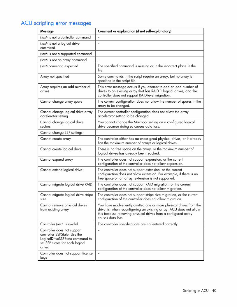
Scripting in ACU 40
ACU scripting error messages
Message Comment or explanation (if not self-explanatory)
(text) is not a controller command --
(text) is not a logical drive command
--
(text) is not a supported command --
(text) is not an array command --
(text) command expected The specified command is missing or in the incorrect place in the file.
Array not specified Some commands in the script require an array, but no array is specified in the script file.
Array requires an odd number of drives
This error message occurs if you attempt to add an odd number of drives to an existing array that has RAID 1 logical drives, and the controller does not support RAID-level migration.
Cannot change array spare The current configuration does not allow the number of spares in the array to be changed.
Cannot change logical drive array accelerator setting
The current controller configuration does not allow the array accelerator setting to be changed.
Cannot change logical drive sectors
You cannot change the MaxBoot setting on a configured logical drive because doing so causes data loss.
Cannot change SSP settings --
Cannot create array The controller either has no unassigned physical drives, or it already has the maximum number of arrays or logical drives.
Cannot create logical drive There is no free space on the array, or the maximum number of logical drives has already been reached.
Cannot expand array The controller does not support expansion, or the current configuration of the controller does not allow expansion.
Cannot extend logical drive The controller does not support extension, or the current configuration does not allow extension. For example, if there is no free space on an array, extension is not supported.
Cannot migrate logical drive RAID The controller does not support RAID migration, or the current configuration of the controller does not allow migration.
Cannot migrate logical drive stripe size
The controller does not support stripe size migration, or the current configuration of the controller does not allow migration.
Cannot remove physical drives from existing array
You have inadvertently omitted one or more physical drives from the drive list when reconfiguring an existing array. ACU does not allow this because removing physical drives from a configured array causes data loss.
Controller (text) is invalid The controller specifications are not entered correctly.
Controller does not support controller SSPState. Use the LogicalDriveSSPState command to set SSP states for each logical drive.
--
Controller does not support license keys
--

Scripting in ACU 41
Message Comment or explanation (if not self-explanatory)
Controller does not support logical drive SSP states. Use the SSPState command to set the controller SSP state.
--
Controller does not support redundancy settings
The controller is not redundant or does not support redundancy settings.
Controller does not support RAIDArrayID
--
Controller does not support SSP --
Controller has maximum number of license keys
--
Controller is locked by another machine or user
--
Controller requires non-failed physical drives to set license keys
--
Controller requires physical drives to set license keys
--
Could not detect controller (text) --
Error communicating with controller
--
Error saving controller There is a problem saving one or more controller configurations.
Failure opening capture file (text) --
Failure opening input file (text) --
Internal error An internal ACU error has occurred, and some error is not being identified properly.
Invalid array accelerator setting The specified array accelerator setting is invalid or is not supported with the current configuration.
Invalid array The array ID is invalid.
Invalid ClearConfigurationWithDataLoss parameter
--
Invalid Controller --
Invalid expand priority The specified expand priority is not supported, or the controller does not allow expansion and therefore does not support the Expand Priority feature.
Invalid license key --
Invalid logical drive The logical drive ID is not valid.
Invalid Method Invalid Method value.
Invalid physical drive The physical drive listed for the array is not a valid physical drive, or it is a physical drive that is not capable of being placed in the array.
Invalid RAIDArrayID The entered RAIDArrayID is invalid. Use characters from the set a–z, A–Z, 0–9, !, @, #, *, (, ), ,, -, _, +, :, ., /, and [space]. The ID cannot end with a space character or exceed the maximum number of characters allowed by the controller.
Invalid RAID The specified RAID level is invalid or is not possible with the current configuration.
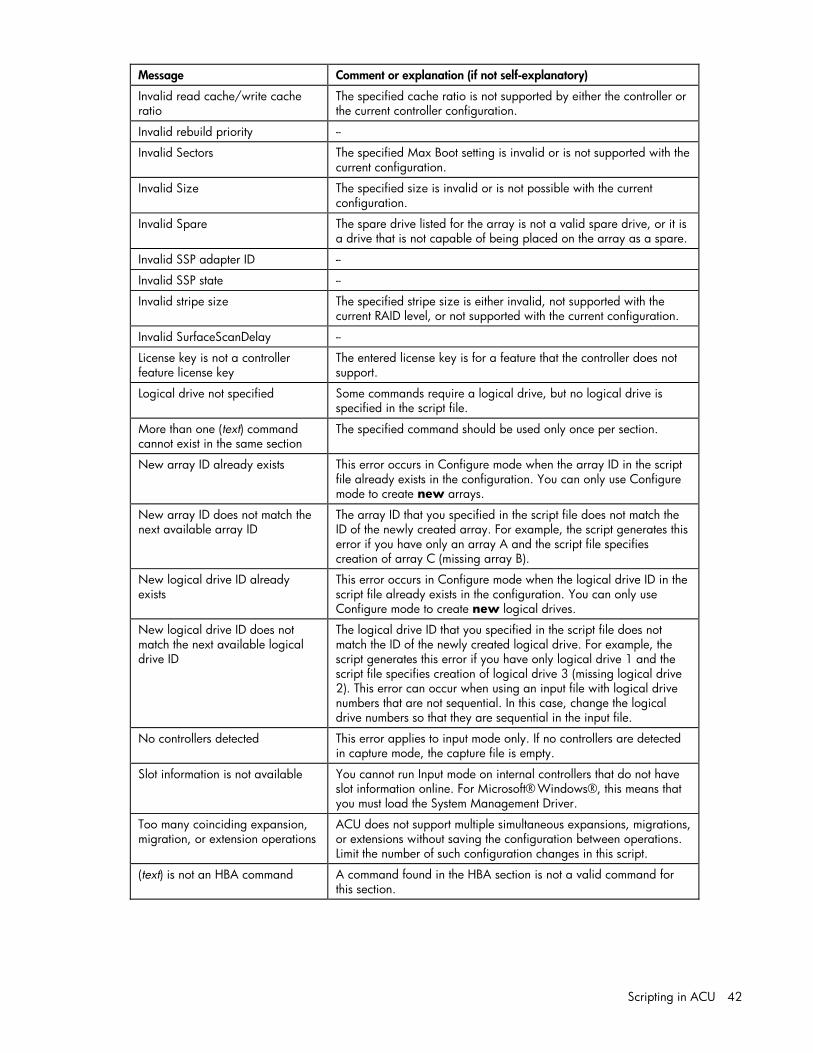
Scripting in ACU 42
Message Comment or explanation (if not self-explanatory)
Invalid read cache/write cache ratio
The specified cache ratio is not supported by either the controller or the current controller configuration.
Invalid rebuild priority --
Invalid Sectors The specified Max Boot setting is invalid or is not supported with the current configuration.
Invalid Size The specified size is invalid or is not possible with the current configuration.
Invalid Spare The spare drive listed for the array is not a valid spare drive, or it is a drive that is not capable of being placed on the array as a spare.
Invalid SSP adapter ID --
Invalid SSP state --
Invalid stripe size The specified stripe size is either invalid, not supported with the current RAID level, or not supported with the current configuration.
Invalid SurfaceScanDelay --
License key is not a controller feature license key
The entered license key is for a feature that the controller does not support.
Logical drive not specified Some commands require a logical drive, but no logical drive is specified in the script file.
More than one (text) command cannot exist in the same section
The specified command should be used only once per section.
New array ID already exists This error occurs in Configure mode when the array ID in the script file already exists in the configuration. You can only use Configure mode to create new arrays.
New array ID does not match the next available array ID
The array ID that you specified in the script file does not match the ID of the newly created array. For example, the script generates this error if you have only an array A and the script file specifies creation of array C (missing array B).
New logical drive ID already exists
This error occurs in Configure mode when the logical drive ID in the script file already exists in the configuration. You can only use Configure mode to create new logical drives.
New logical drive ID does not match the next available logical drive ID
The logical drive ID that you specified in the script file does not match the ID of the newly created logical drive. For example, the script generates this error if you have only logical drive 1 and the script file specifies creation of logical drive 3 (missing logical drive 2). This error can occur when using an input file with logical drive numbers that are not sequential. In this case, change the logical drive numbers so that they are sequential in the input file.
No controllers detected This error applies to input mode only. If no controllers are detected in capture mode, the capture file is empty.
Slot information is not available You cannot run Input mode on internal controllers that do not have slot information online. For Microsoft® Windows®, this means that you must load the System Management Driver.
Too many coinciding expansion, migration, or extension operations
ACU does not support multiple simultaneous expansions, migrations, or extensions without saving the configuration between operations. Limit the number of such configuration changes in this script.
(text) is not an HBA command A command found in the HBA section is not a valid command for this section.

Using the Command Line Interface 43
Using the Command Line Interface
In this section Overview of the ACU CLI ........................................................................................................................ 43 Typical procedures ................................................................................................................................. 45
Overview of the ACU CLI The ACU CLI is an interactive command console that provides immediate feedback to the user and is functionally equivalent to the ACU GUI.
The executable for the CLI is available from the HP PSP for Microsoft® Windows® or from the HP website.
Running the CLI You can open the CLI in either Console mode or Command mode. In Console mode, you can adjust several configuration parameters on several devices without having to restart ACU each time. Command mode is more suitable for an isolated change of just one configuration parameter on one device.
The syntax of the command required to open the ACU CLI depends on the operating system that you are using and the mode that you want to use. • Console mode
Windows: C:\Program Files\Compaq\Hpacucli\Bin\hpacucli.exe
Alternatively, click Start, and navigate to Programs > HP System Tools > HP Array Configuration Utility CLI. Linux:
[root@localhost root]# hpacucli
After you have entered Console mode in either operating system, the screen displays the following message and console prompt:
HP Array Configuration Utility CLI 7.15.17.0 Detecting Controllers...Done. Type "help" for a list of supported commands. Type "exit" to close the console. =>
• Command mode To use Command mode, add the specific ACU CLI command ("The <command> variable" on page 44) to the end of the text line used to open ACU in Console mode before you press the Enter key. The following examples use help as the specific ACU CLI command. Windows:
C:\Program Files\Compaq\Hpacucli\Bin\hpacucli.exe help
Linux: [root@localhost root]# hpacucli help

Using the Command Line Interface 44
The remaining examples in this chapter are described as if entered in Console mode.
CLI syntax Whether entered in Command mode or Console mode, a typical ACU CLI command line consists of three parts: a target device, a command, and a parameter with values if necessary. Using angle brackets to denote a required variable and plain brackets to denote an optional variable, the structure of a typical ACU CLI command line is as follows: <target> <command> [parameter=value]
The <target> variable This variable provides the path to a target device. The device can be a controller, an array, a logical drive, or a physical drive.
For example: controller slot=3 controller wwn=500805F3000BAC11 controller serialnumber=P56350D9IP903J controller slot=3 array A controller chassisname="A" array A logicaldrive 2 controller chassisname="A" physicaldrive 1:0
You can also specify that an operation be performed on several similar devices at the same time.
For example: controller all controller slot=3 logicaldrive 2
The <command> variable The <command> variable can be any of the following words or phrases: add create delete help modify remove rescan set target show
Some commands require a parameter, and some parameters require a value. The descriptions of the commands in the rest of this chapter provide examples of some usable parameters and variables for those cases that need them.
Keyword abbreviations Several commonly used keywords in the ACU CLI have acceptable abbreviations, as shown in the following table.
Keyword Abbreviation in ACU CLI
Keyword Abbreviation in ACU CLI
adapterid ai logicaldrive ld
arrayaccelerator aa parallelscsi ps
cacheratio cr physicaldrive pd

Using the Command Line Interface 45
Keyword Abbreviation in ACU CLI
Keyword Abbreviation in ACU CLI
chassisname* ch rebuildpriority rp
chassisslot chs redundantcontroller rc
connectionname cn serialnumber sn
controller ctrl stripesize ss
drivetype dt surfacescandelay ssd
drivewritecache dwc tapedrive td
expandpriority ep
*The CLI also uses this keyword and abbreviation for the terms box name and RAID array ID.
Hiding warning prompts When you enter a command for an operation that can potentially destroy user data, the CLI displays a warning and prompts you for input (a y or an n) before continuing the operation. This situation is undesirable when running batch file scripts. To prevent warning prompts from being displayed, use the term forced as a parameter.
Example command: ctrl ch="Lab4" ld 1 delete forced
Querying a device If you do not know what values a parameter can have, you can sometimes query the device to find out by entering a ? as the value of the parameter.
Example command: => ctrl ch="Lab4" ld 1 modify raid = 0 ss=?
A typical screen response in this case could be: Available options are:
8 16 (current value) 32 64 128 (default) 256
For information about which parameters can be queried, refer to the CLI help ("Help" on page 45).
Help To get help with the CLI, enter help at the CLI prompt as follows: => help
This command does not need a target variable or a parameter.
Typical procedures The following sections describe some common ACU CLI procedures.

Using the Command Line Interface 46
Creating a logical drive When you use the CLI to create a logical drive, the array that holds the logical drive is created implicitly. (This is different from the GUI procedure, in which the array is created explicitly).
Syntax <target> create type=ld [parameter=value]
• To create a logical drive on a new array, specify both the controller and the drives that are to constitute the new array. For example:
ctrl slot=5 create type=ld drives=1:0,1:1,1:3 raid=adg
• To create a logical drive on an existing array, specify the array. You do not need to specify the drives in this case because they are already defined. For example:
ctrl slot=5 array A create type=ld size=330 raid=adg
Standard parameters for creating a logical drive are described in the following table. If you do not specify a particular parameter when creating a logical drive, the CLI uses the default value for that parameter.
Parameter Acceptable values Comments
drives #:#|all|allunassigned Default setting is all.
raid adg|5|4|1+0|1|0|? Default setting is the highest level that the logical drive can accept.
ss 8|16|32|64|128|256|default|? Units are KB.* Default setting depends on the RAID level.
size #|max|? This parameter determines the desired size of the logical drive. Units are MB.* Default setting is max.
sectors 32|63|default Default setting depends on the operating system.
aa enable|disable Default setting is enable.
*Use only these units. Do not enter any extra text into the command to specify the units.
Sample scenario Consider a situation in which you want to create two arrays. One of these arrays needs two logical drives, while the other needs only one.
First, determine what physical drives are available and what their properties are: => ctrl ch="Lab 4" pd all show
For this sample scenario, the screen response is: MSA1000 at Lab 4
unassigned physicaldrive 1:12 (box 1:bay12, Parallel SCSI, 36.4 GB, OK) physicaldrive 1:13 (box 1:bay13, Parallel SCSI, 9.1 GB, OK) physicaldrive 1:14 (box 1:bay14, Parallel SCSI, 9.1 GB, OK)
Knowing this information, you can now create the first array with one logical drive: => ctrl ch="Lab 4" create type=ld drives=1:12
Now, verify that the array has been created: => ctrl ch="Lab 4" pd all show
In this case, the screen response is: MSA1000 at Lab 4
array A

Using the Command Line Interface 47
physicaldrive 1:12 (box 1:bay12, Parallel SCSI, 36.4 GB, OK) unassigned
physicaldrive 1:13 (box 1:bay13, Parallel SCSI, 9.1 GB, OK) physicaldrive 1:14 (box 1:bay14, Parallel SCSI, 9.1 GB, OK)
The second array is to be created on the two remaining physical drives. Before creating this array, determine what RAID options are available for these drives: => ctrl ch="Lab 4" create type=ld drives=1:13,1:14 size=300 raid=?
The response in this case is: Available options are:
0 1+0 (default value)
Now create the new array: => ctrl ch="Lab 4" create type=ld drives=1:13,1:14 size=300 raid=1+0
It is not strictly necessary to specify the RAID level in this example because it is the highest possible level for this scenario and will be used by default. However, it is included in the command as an example.
Now verify that the array has been formed: => ctrl ch="Lab 4" pd all show
The screen response is: MSA1000 at Lab 4
array A physicaldrive 1:12 (box 1:bay12, Parallel SCSI, 36.4 GB, OK)
array B physicaldrive 1:13 (box 1:bay13, Parallel SCSI, 9.1 GB, OK) physicaldrive 1:14 (box 1:bay14, Parallel SCSI, 9.1 GB, OK)
Create the second logical drive on this array. There are two possible ways for creating subsequent logical drives. You can create logical drives by specifying the implicitly created array name shown in example A. You can also use the physical drives in the array to distinguish which array to create the logical drives shown in example B.
Example: a. => ctrl ch="Lab 4" array B create type=ld size=900 b. => ctrl ch="Lab 4" create type=ld drives=1:9,1:10 size=333
Finally, verify that the logical drives have all been created correctly: => ctrl ch="Lab 4" ld all show MSA1000 at Lab 4
array A logicaldrive 1 (33.9 GB, RAID 0, OK)
array B logicaldrive 2 (298 MB, RAID 1+0, OK) logicaldrive 3 (896 MB, RAID 1+0, OK)
Modifying the controller chassis name If a controller is configured with at least one logical drive, you can assign the controller a simplified name (the chassis name) to make it easier to identify and enter the correct controller in a command.
Syntax: <target> modify ch="new chassis name"
where <target> is a controller.
Example commands: => ctrl sn=P56350D9IP903J modify ch="Lab 6"
Using the Command Line Interface 48
=> ctrl ch="Lab 4" modify ch="Lab 6"
Using Selective Storage Presentation SSP (also known as Access Control List commands) enables you to specify which host controllers are to have access to particular logical drives. This feature prevents data corruption that can occur when different servers using different operating systems access the same data.
Using SSP requires two commands: • The first command activates the SSP feature on the controller. • The second command specifies the logical drives that need access control. This command also
specifies the adapter IDs or the connection names that are to be allowed or denied access to the logical drives.
Activating SSP on a controller can be thought of as modifying the controller access to the SSP feature. The standard syntax for this operation is thus: <target> modify ssp=on|off [forced]
where <target> in most cases is the controller itself, but for an RA4x00, it is a logical drive on the controller.
When you first activate SSP on a controller or logical drive, the logical drives are inaccessible to all adapter IDs by default. The adapter IDs are said to be masked. Because masking prevents access to the logical drives, the CLI normally displays a warning prompt when you enter the command to activate SSP. To prevent the prompt from appearing (when using this command in a batch file script, for example), add the forced parameter.
After you have activated SSP, unmask devices by either their adapter IDs or their connection names using the following syntax: <target> modify mask|unmask=#,#,...|all [forced]
where <target> is a logical drive.
Example commands: => ctrl ch="Lab 3" modify ssp=on forced => ctrl ch="Lab 4" ld 1 modify mask=210000E08B07A68F => ctrl ch="Lab 4" ld all modify unmask="cnxn 3","cnxn 4"
Sample scenario First, check the SSP status of the controller: => ctrl ch="Lab 4" show ssp
A typical screen response could be: MSA1000 at Lab 4
Adapter ID: 210000E08B07A68F connectionname: Unknown Location: Local Status: Online Host Mode: Default
Adapter ID: 5034414235583942 connectionname: Unknown Location: Unknown Status: Offline Host Mode: Default
Now activate SSP, and then show the logical drives that are present so that you can determine which drive to unmask: => ctrl ch="Lab 4" modify ssp=on forced

Using the Command Line Interface 49
=> ctrl ch="Lab 4" ld all show MSA1000 at Lab 4
array A logicaldrive 1 (33.9 GB, RAID 0, OK)
array B logicaldrive 2 (298 MB, RAID 1+0, OK) logicaldrive 3 (896 MB, RAID 1+0, OK)
Finally, unmask an adapter ID and then check the SSP status: => ctrl ch="Lab 4" ld 1 modify unmask 210000E08B07A68F => ctrl ch="Lab 4" show ssp MSA1000 at Lab 4
Adapter ID: 210000E08B07A68F connectionname: Unknown Location: Local Status: Online Host Mode: Default logicaldrive 1 is unmasked
Adapter ID: 5034414235583942 connectionname: Unknown Location: Unknown Status: Offline Host Mode: Default logicaldrive 1 is masked
Modifying connection names You can convert a lengthy adapter ID into a brief connection name that can be used in all future commands.
Syntax: <target> modify ai=# cn="connection name"
where <target> is a controller that supports SSP.
Example command: ctrl ch="Lab 4" ld 1 modify ai=210000E08B07A68F cn="cnxn 3"
Managing host modes (connection profiles) Syntax: <target> modify ai=# hostmode="operating system type"|?
where <target> is a controller that supports host modes.
Example command: => ctrl ch="Lab 3" modify ai=5034414235583942 hostmode=?
NOTE: The connection name and the logical unit are required for managing host modes.
A typical response in this case could be: hostmode options:
Default Windows OpenVMS Tru64 Linux Solaris

Using the Command Line Interface 50
NetWare HP
Deleting target devices Syntax: <target> delete [forced]
where <target> can be a controller, array, or logical drive. Except in the case of controllers, you can delete several devices simultaneously if they are of similar type by using the all keyword.
Because deleting a target device can result in data loss, the screen displays a warning prompt unless you include the forced parameter.
Example commands: => ctrl ch="Lab 4" delete forced => ctrl slot=3 ld all delete
Identifying devices You can enter a command that causes the LEDs on target devices to blink, enabling you to identify the devices. The LEDs continue to blink until you enter the command to stop them blinking.
Syntax: <target> modify led=on|off
Example commands: => ctrl ch="Lab 4" modify led=on => ctrl ch="Lab 4" modify array A led=off
Expanding an array You can increase the storage space on an array by adding physical drives. The restrictions are that the added drives must be of the same type (for example, parallel SCSI or SATA), and they must each have a capacity no less than that of the existing drives in the array.
IMPORTANT: An array expansion, logical drive extension, or logical drive migration takes about 15 minutes per gigabyte, or considerably longer if the controller does not have a battery-backed cache. While this process is occurring, no other expansion, extension, or migration can occur simultaneously on the same controller.
Syntax: <target> add drives=#:#,#:#,...|allunassigned [forced]
where <target> is an array (or a logical drive, if the array contains only one logical drive).
If you add an odd number of drives to an array that contains at least one RAID 1+0 logical drive, the CLI displays a prompt that asks if it is acceptable to convert the RAID 1+0 logical drive to RAID 5 (or RAID ADG if the controller supports this RAID level). Adding the forced parameter to the command prevents this prompt from appearing.
Example commands: => ctrl slot=3 array A add drives=1:0,1:1 => ctrl slot=4 ld 1 add drives=allunassigned
Extending a logical drive If the operating system supports logical drive extension, you can use any unassigned capacity on an array to enlarge one or more of the logical drives on the array.

Using the Command Line Interface 51
IMPORTANT: An array expansion, logical drive extension, or logical drive migration takes about 15 minutes per gigabyte, or considerably longer if the controller does not have a battery-backed cache. While this process is occurring, no other expansion, extension, or migration can occur simultaneously on the same controller.
Syntax: <target> modify size=#|max|? [forced]
where <target> is a logical drive.
If the operating system does not support logical drive extension, carrying out this command would make data on the logical drive unavailable. Therefore, the CLI displays a warning prompt as a safeguard in case you are using such an operating system. To prevent the prompt from appearing, use the forced parameter.
Example commands: => ctrl slot=3 ld 1 modify size=max => ctrl slot=4 ld 1 modify size=? => ctrl slot=3 ld 2 modify size=500 forced
Managing spare drives Assigning online spares to an array enables you to postpone replacement of faulty drives. However, it does not increase the fault-tolerance level of any logical drives in the array. For example, a logical drive in a RAID 5 configuration suffers irretrievable data loss if two physical drives fail, regardless of the number of spare drives assigned to it.
Syntax: <target> add spares=#:#,#:#,...|allunassigned <target> remove spares=#:#,#:#,...|all
where <target> is an array. In cases where the array contains only one logical drive, the logical drive can also be the target.
Example commands: => ctrl slot=3 array B add spares=1:6 => ctrl slot=4 array all add spares=1:5,1:7
Migrating a logical drive This command enables you to adjust the stripe size (data block size) or RAID level of a selected logical drive. For information about selecting an appropriate stripe size or RAID level, refer to the tables in the "Creating a logical drive (on page 17)" and "Selecting a RAID method (on page 65)" sections.
Consider the following factors before performing a migration: • For some RAID-level migrations to be possible, you might need to add one or more drives to the
array. • For migration to a larger stripe size to be possible, the array might need to contain unused drive
space. This extra space is necessary because some of the larger data stripes in the migrated array are likely to be inefficiently filled.
IMPORTANT: An array expansion, logical drive extension, or logical drive migration takes about 15 minutes per gigabyte, or considerably longer if the controller does not have a battery-backed cache. While this process is occurring, no other expansion, extension, or migration can occur simultaneously on the same controller.
Syntax: <target> modify [raid=0|1+0|1|5|6|adg|?] [ss=8|16|32|64|128|256|default|?]

Using the Command Line Interface 52
where <target> is a logical drive.
The following limitations apply to this command: • You cannot simultaneously query the RAID level and the stripe size of any given logical drive. • If you do not specify a RAID level for a query or migration, the CLI uses the existing value by default. • If you do not specify a stripe size, the CLI uses the default stripe size value for the RAID level that you
specify.
Example commands: => ctrl slot=3 ld 1 modify raid=1 => ctrl slot=4 ld 2 modify ss=16 => ctrl slot=2 ld 3 modify raid=5 ss=16
Changing the Rebuild Priority setting The Rebuild Priority setting determines the urgency with which the controller treats an internal command to rebuild a failed logical drive. • At the low setting, normal system operations take priority over a rebuild. • At the medium setting, rebuilding occurs for half of the time, and normal system operations occur for
the rest of the time. • At the high setting, the rebuild takes precedence over all other system operations.
If the logical drive is part of an array that has an online spare, rebuilding begins automatically when drive failure occurs. If the array does not have an online spare, rebuilding begins when the failed physical drive is replaced.
Syntax: <target> modify rp=high|medium|low
where <target> is a controller.
Example command: => ctrl slot=3 modify rp=high
Changing the Expand Priority setting The Expand Priority setting determines the urgency with which the controller treats an internal command to expand an array. • At the low setting level, normal system operations take priority over an array expansion. • At the medium setting, expansion occurs for half of the time, and normal system operations occur for
the rest of the time. • At the high setting, the expansion takes precedence over all other system operations.
Syntax: <target> modify ep=high|medium|low
where <target> is a controller.
Example command: => ctrl slot=3 modify ep=high
Changing the controller cache ratio The controller cache ratio setting determines the amount of memory allocated to read and write operations. Different types of applications have different optimum settings. You can change the ratio only
Using the Command Line Interface 53
if the controller has a battery-backed cache (because only battery-backed cache can be used for write cache) and if there are logical drives configured on the controller.
Syntax: <target> modify cr=#/#|?
where <target> is a controller, and #/# is the cache ratio in the format read percentage/write percentage.
Example command: => ctrl slot=3 modify cr=25/75
Changing the surface scan delay time The setting for the surface scan delay determines the time interval for which a controller must be inactive before a surface scan analysis is started on the physical drives that are connected to it.
Surface scan analysis is an automatic background process that ensures that you can recover data if a drive failure occurs. The scanning process checks physical drives in fault-tolerant logical drives for bad sectors, and in RAID 5 or RAID 6 (ADG) configurations, it also verifies the consistency of parity data.
Syntax: <target> modify ssd=#
where <target> is a controller and # is a number between 1 and 30. This number determines the delay time in seconds, but you do not need to include units with the command.
Example command: => ctrl sn=P56350D9IP903J modify ssd=3
Re-enabling a failed logical drive If a logical drive has failed and the data on it is invalid or non-recoverable, you can re-enable the logical drive so that it can be reused. This process preserves the structure of the logical drive and merely deletes data, whereas a delete command applied to a logical drive deletes the logical drive structure as well as the data.
Syntax: <target> modify reenable [forced]
Example command: => ctrl slot=3 ld 1 modify reenable forced
Enabling or disabling the drive cache On controllers and drives that support physical drive write cache, you can use this command to enable or disable the write cache for all drives on the controller.
CAUTION: Because physical drive write cache is not battery-backed, you could lose data if a power failure occurs during a write process. To minimize this possibility, use a backup power supply.
Syntax: <target> modify drivewritecache=enable|disable [forced]
where <target> is a controller that supports drive write cache.
Example command: => ctrl slot=5 modify dwc=enable

Using the Command Line Interface 54
Enabling or disabling the array accelerator If the controller has an array accelerator, you can disable it or re-enable it for specified logical drives.
NOTE: Disabling the array accelerator for a logical drive reserves use of the accelerator cache for other logical drives on the array. This feature is useful if you want the other logical drives to have the maximum possible performance (for example, if the logical drives contain database information).
Syntax: <target> modify aa=enable|disable
where <target> is a logical drive.
Example command: => ctrl slot=3 ld 1 modify aa=enable
Disabling a redundant controller This command disables a redundant controller that is in an Active-Standby configuration.
IMPORTANT: The redundant controller cannot be re-enabled after you have disabled it.
Syntax: <target> modify redundantcontroller=disable
where <target> is a controller that has an enabled redundant controller.
Example command: => ctrl ch="redundant Lab4" modify rc=disable
Setting the target If you must perform several operations on a given target device, you can simplify the required commands by setting the device as the default <target> for the CLI operations.
After you have set the target, any command that you enter in the CLI without a specified <target> is automatically applied to the set target. If you must also perform operations on other devices, you can still do so at any time by specifying the <target> for each of those operations as usual. You can also change the set target or clear it completely. The set target is automatically cleared when you close the CLI.
IMPORTANT: You cannot use the set target command in batch file scripts.
Syntax: set target <target>
where <target> is a controller, array, or logical drive.
Example commands: => set target ctrl slot=3 => clear target
Typical scenario
First, set a target as follows: => set target ctrl ch="Lab 4" => show target controller chassisname="Lab 4"
As an example of how the set target command works, check the status of array A on this controller: => array A show MSA1000 at Lab 4

Using the Command Line Interface 55
array A Interface Type: Parallel SCSI Unused Space: 7949 MB Status: OK
Note that the controller does not need to be specified because it is currently the set target.
Now clear the target, reset it, and enter a few commands for the new set target: => clear target => set target ctrl slot=3 => array A add drives=1:7,1:8,1:9 => array B add spares=1:10,1:11 => ctrl slot=4 ld 3 modify ss=64 => modify rp=high
This sequence includes a command for a different target (the controller in slot 4) as a demonstration. Note that the next command in the sequence (the one for modifying the rebuild priority) applies to the controller in slot 3, not the one in slot 4. This is because the command does not specify a <target> for the rebuild priority, so the default set target is used instead.
Rescanning the system A rescan detects devices that have been added to the system since the previous rescan or since the ACU CLI was started, whichever is more recent.
Syntax:
Use the word rescan directly at the ACU CLI prompt, without any target device or parameters.
Example command: => rescan

Probability of logical drive failure 56
Probability of logical drive failure
In this section Factors involved in logical drive failure ..................................................................................................... 56
Factors involved in logical drive failure The probability that a logical drive will fail depends on the RAID-level setting and on the number and type of physical drives in the array. If the logical drive does not have an online spare, the following results apply: • A RAID 0 logical drive fails if only one physical drive fails. • A RAID 1+0 logical drive fails if any two failed physical drives are mirrored to each other.
• The maximum number of physical drives that can fail without causing failure of the logical drive is n/2, where n is the number of hard drives in the array. In practice, a logical drive usually fails before this maximum is reached. As the number of failed physical drives increases, it becomes increasingly likely that the newly failed drive is mirrored to a previously failed drive.
• The minimum number of physical drive failures that can cause the logical drive to fail is two. This situation occurs when the two failed drives are mirrored to each other. As the total number of drives in the array increases, the probability that the only two failed drives in an array are mirrored to each other decreases.
• A RAID 5 logical drive fails if two physical drives fail. • A RAID 6 (ADG) logical drive fails when three physical drives fail.
At any given RAID level, the probability of logical drive failure increases as the number of physical drives in the logical drive increases. This principle is illustrated more quantitatively in the graph ("Probability of logical drive failure vs. number of drives in array" on page 57). The data for this graph is calculated from the MTBF value for a typical physical drive, assuming that no online spares are present. If an online spare is added to any of the fault-tolerant RAID configurations, the probability of logical drive failure is further decreased.
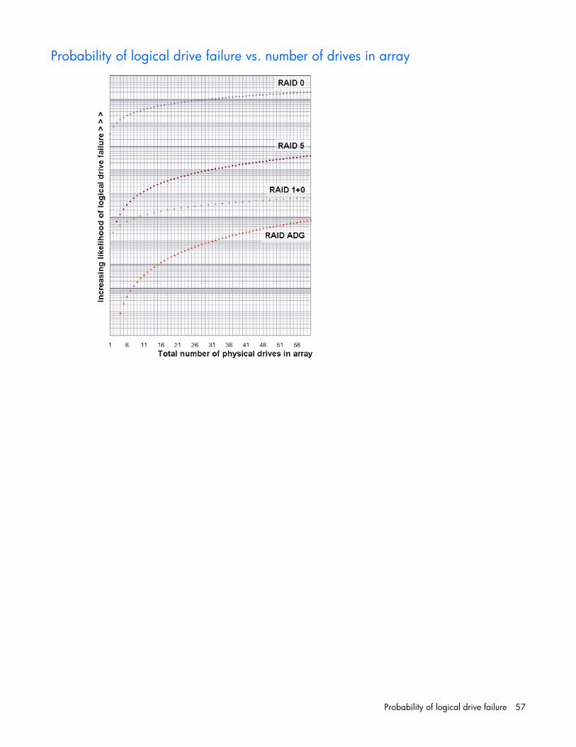
Probability of logical drive failure 57
Probability of logical drive failure vs. number of drives in array

Drive arrays and fault-tolerance methods 58
Drive arrays and fault-tolerance methods
In this section Drive arrays........................................................................................................................................... 58 Fault-tolerance methods........................................................................................................................... 60
Drive arrays The capacity and performance of a single physical (hard) drive is adequate for home users. However, business users demand higher storage capacities, higher data transfer rates, and greater protection against data loss when drives fail.
Connecting extra physical drives (Pn in the figure) to a system increases the total storage capacity but has no effect on the efficiency of read/write (R/W) operations. Data can still be transferred to only one physical drive at a time.

Drive arrays and fault-tolerance methods 59
With an array controller installed in the system, the capacity of several physical drives can be combined into one or more virtual units called logical drives (also called logical volumes and denoted by Ln in the figures in this section). Then, the read/write heads of all the constituent physical drives are active simultaneously, reducing the total time required for data transfer.
Because the read/write heads are active simultaneously, the same amount of data is written to each drive during any given time interval. Each unit of data is called a block (denoted by Bn in the figure), and adjacent blocks form a set of data stripes (Sn) across all the physical drives that comprise the logical drive.
For data in the logical drive to be readable, the data block sequence must be the same in every stripe. This sequencing process is performed by the array controller, which sends the data blocks to the drive write heads in the correct order.
A natural consequence of the striping process is that each physical drive in a given logical drive will contain the same amount of data. If one physical drive has a larger capacity than other physical drives in the same logical drive, the extra capacity is wasted because it cannot be used by the logical drive.
The group of physical drives containing the logical drive is called a drive array, or just array (denoted by An in the figure). Because all the physical drives in an array are commonly configured into just one

Drive arrays and fault-tolerance methods 60
logical drive, the term array is often used as a synonym for logical drive. However, an array can contain several logical drives, each of a different size.
Each logical drive in an array is distributed across all of the physical drives within the array. A logical drive can also extend across more than one port on the same controller, but it cannot extend across more than one controller.
Drive failure, although rare, is potentially catastrophic. For arrays that are configured as shown in the previous figure, failure of any physical drive in the array causes every logical drive in the array to suffer irretrievable data loss. To protect against data loss due to physical drive failure, logical drives are configured with fault tolerance ("Fault-tolerance methods" on page 60).
For any configuration except RAID 0, further protection against data loss can be achieved by assigning a drive as an online spare (or hot spare). This drive contains no data and is connected to the same controller as the array. When any other physical drive in the array fails, the controller automatically rebuilds information that was originally on the failed drive to the online spare. The system is thus restored to full RAID-level data protection, although it now no longer has an online spare. (However, in the unlikely event that another drive in the array fails while data is being rewritten to the spare, the logical drive will still fail.)
When you configure an online spare, it is automatically assigned to all logical drives in the same array. Additionally, you do not need to assign a separate online spare to each array. Instead, you can configure one hard drive to be the online spare for several arrays if the arrays are all on the same controller.
Fault-tolerance methods Several fault-tolerance methods exist. Those most often used with Smart Array controllers are hardware-based RAID methods.
Two alternative fault-tolerance methods that are sometimes used are also described ("Alternative fault-tolerance methods" on page 65). However, hardware-based RAID methods provide a much more robust and controlled fault-tolerance environment, so these alternative methods are seldom used.
Hardware-based fault-tolerance methods HP recommends the following hardware-based methods for use with Smart Array controllers: • RAID 0—Data Striping only (no fault tolerance)

Drive arrays and fault-tolerance methods 61
• RAID 1+0—Drive Mirroring • RAID 5—Distributed Data Guarding • RAID 6 (ADG)—Advanced Data Guarding
RAID 0—No fault tolerance A RAID 0 configuration provides data striping, but there is no protection against data loss when a drive fails. However, it is useful for rapid storage of large amounts of noncritical data (for printing or image editing, for example) or when cost is the most important consideration.
Advantages: • Has the highest write performance of all RAID methods. • Has the lowest cost per unit of stored data of all RAID methods. • All drive capacity is used to store data (none is needed for fault tolerance).
Disadvantages: • All data on the logical drive is lost if a physical drive fails. • Cannot use an online spare. • Can only preserve data by backing it up to external drives.

Drive arrays and fault-tolerance methods 62
RAID 1+0—drive mirroring In a RAID 1+0 configuration, data is duplicated to a second drive.
When the array has more than two physical drives, drives are mirrored in pairs.
In each mirrored pair, the physical drive that is not busy answering other requests answers any read requests that are sent to the array. (This behavior is called load balancing.) If a physical drive fails, the remaining drive in the mirrored pair can still provide all the necessary data. Several drives in the array can fail without incurring data loss, as long as no two failed drives belong to the same mirrored pair.
This fault-tolerance method is useful when high performance and data protection are more important than the cost of physical drives.
NOTE: When there are only two physical drives in the array, this fault-tolerance method is often referred to as RAID 1.
Advantages: • Has the highest read performance of any fault-tolerant configuration.

Drive arrays and fault-tolerance methods 63
• No data is lost when a drive fails, as long as no failed drive is mirrored to another failed drive (up to half of the physical drives in the array can fail).
Disadvantages: • This method is expensive (many drives are needed for fault tolerance). • Only half of the total drive capacity is usable for data storage.
RAID 5—distributed data guarding In a RAID 5 configuration, data protection is provided by parity data (denoted by Px,y in the figure). This parity data is calculated stripe by stripe from the user data that is written to all other blocks within that stripe. The blocks of parity data are distributed evenly over every physical drive within the logical drive.
When a physical drive fails, data that was on the failed drive can be calculated from the remaining parity data and user data on the other drives in the array. This recovered data is usually written to an online spare in a process called a rebuild.
This configuration is useful when cost, performance, and data availability are equally important.
Advantages: • Has high read performance. • Data is not lost if one physical drive fails. • More drive capacity is usable than with RAID 1+0—parity information requires only the storage
space equivalent to one physical drive.
Disadvantages: • Has relatively low write performance. • Data is lost if a second drive fails before data from the first failed drive is rebuilt.
RAID 6 (ADG)—Advanced Data Guarding
NOTE: Not all controllers support RAID 6 (ADG).
RAID 6 (ADG), like RAID 5, generates and stores parity information to protect against data loss caused by drive failure. With RAID 6 (ADG), however, two different sets of parity data are used (denoted by Px,y

Drive arrays and fault-tolerance methods 64
and Qx,y in the figure), allowing data to still be preserved if two drives fail. Each set of parity data uses a capacity equivalent to that of one of the constituent drives.
This method is most useful when data loss is unacceptable but cost is also an important factor. The probability that data loss will occur when an array is configured with RAID 6 (ADG) is less than it would be if it was configured with RAID 5.
Advantages: • This method has a high read performance. • This method allows high data availability—Any two drives can fail without loss of critical data. • More drive capacity is usable than with RAID 1+0—Parity information requires only the storage
space equivalent to two physical drives.
Disadvantages:
The main disadvantage of RAID 6 (ADG) is a relatively low write performance (lower than RAID 5) because of the need for two sets of parity data.
Comparing the hardware-based RAID methods
NOTE: Not all controllers support RAID 6 (ADG).
Item RAID 0 RAID 1+0 RAID 5 RAID 6 (ADG)
Alternative name Striping (no fault tolerance)
Mirroring Distributed Data Guarding
Advanced Data Guarding
Formula for number of drives usable for data (n = total number of drives in array)
n n/2 n-1 n-2
Fraction of drive space usable* 100% 50% 67% to 93% 50% to 96%
Minimum number of physical drives
1 2 3 4
Tolerates failure of one physical drive
No Yes Yes Yes

Drive arrays and fault-tolerance methods 65
Item RAID 0 RAID 1+0 RAID 5 RAID 6 (ADG)
Tolerates simultaneous failure of more than one physical drive
No Only if no two failed drives are in the same mirrored pair
No Yes
Read performance High High High High
Write performance High Medium Low Low
Relative cost Low High Medium Medium
*Values for the fraction of drive space usable are calculated with these assumptions: (1) all physical drives in the array have the same capacity; (2) online spares are not used; (3) no more than 14 physical drives are used per array for RAID 5; and (4) no more than 56 drives are used with RAID 6 (ADG).
Selecting a RAID method
NOTE: Not all controllers support RAID 6 (ADG).
Most important criterion Also important Suggested RAID level
Fault tolerance Cost effectiveness
I/O performance
RAID 6 (ADG)
RAID 1+0
Cost effectiveness Fault tolerance
I/O performance
RAID 6 (ADG)
RAID 5 (RAID 0 if fault tolerance is not required)
I/O performance Cost effectiveness
Fault tolerance
RAID 5 (RAID 0 if fault tolerance is not required)
RAID 1+0
Alternative fault-tolerance methods Your operating system may also support software-based RAID or controller duplexing. • Software-based RAID resembles hardware-based RAID, except that the operating system works
with logical drives as if they were physical drives. To protect against data loss caused by physical drive failure, each logical drive must be in a different array from the others.
• Controller duplexing uses two identical controllers with independent, identical sets of drives containing identical data. In the unlikely event of a controller failure, the remaining controller and drives will service all requests.
Neither of these alternative fault-tolerance methods supports online spares or automatic data recovery, nor do they support auto-reliability monitoring or interim data recovery.
If you decide to use one of these alternative methods, configure your arrays with RAID 0 for maximum storage capacity and refer to your operating system documentation for further implementation details.

Diagnosing array problems 66
Diagnosing array problems
In this section Diagnostic tools ..................................................................................................................................... 66
Diagnostic tools Several diagnostic tools provide feedback about problems with arrays. The most important are: • ADU
This utility is available on the SmartStart CD. The meanings of the various ADU error messages are provided in the HP Servers Troubleshooting Guide.
• POST messages Smart Array controllers produce diagnostic error messages at reboot. Many of these POST messages are self-explanatory and suggest corrective actions. For more information about POST messages, refer to the HP Servers Troubleshooting Guide.
• Server Diagnostics To use Server Diagnostics: a. Insert the SmartStart CD into the server CD-ROM drive. b. Click Agree when the license agreement is displayed, and select the Maintenance tab. c. Click Server Diagnostics, and follow the on-screen prompts and instructions.

Acronyms and abbreviations 67
Acronyms and abbreviations
ACR
Array Configuration Replicator
ADG
Advanced Data Guarding (also known as RAID 6)
ADU
Array Diagnostics Utility
CLI
Command Line Interface
GUI
graphical user interface
HBA
host bus adapter
MSA
Modular Smart Array
MTBF
mean time between failures
POST
Power-On Self Test
PSP
ProLiant Support Pack
RAID
redundant array of inexpensive (or independent) disks
SA
Smart Array

Acronyms and abbreviations 68
SSP
Selective Storage Presentation
WBEM
Web-Based Enterprise Management
WWN
World Wide Name

Index 69
A ADU (Array Diagnostic Utility) 66 array accelerator, disabling 17, 21, 54 array capacity expansion 24 array concepts 58 array configuration, copying 31 array expansion, setting priority of 21 array, creating 14, 15
B browser mode 8
C cache ratio, setting 21, 35 clear a configuration 20 CLI (Command Line Interface) 43 configuration modes 10 configuring an array 15, 21 connection name 39, 49 controller duplexing 65
D data protection methods 60, 65 default settings 32 delete a configuration 20 diagnostic tools 66 disable array accelerator 17, 21, 54 disable redundant controller 54 display settings 5 drive array concepts 58 drive cache, disabling 53 duplexing 65
E enable array accelerator 17, 21, 54 error messages 39, 66 execution modes 6 expand priority, setting 21 expanding an array 24 Express mode 12, 14, 20
extending logical drive capacity 25, 38
F failed logical drive, re-enabling 53 fault-tolerance methods 60
H HBA WWN 39 host mode 39, 49
I identifying devices 50 installation instructions 5
L Local Application mode 6, 7 logical drive capacity extension 25 logical drive, creating 17, 22, 58 logical drive, description of 58 logical drive, failed, re-enabling 53 logical drive, failure of 56 logical drive, migrating 25
M MaxBoot setting 17, 38 migrating stripe size 25 modes of operation 6, 31 monitor resolution 5
O operating modes 7, 10 operating systems supported 5 overview of configuration procedure 6
P POST error messages 66 probability of logical drive failure 56
R RAID level migration 25
Index

Index 70
RAID levels 60, 61, 62, 63 RAID levels, comparison of features 64 RAID, software-based 65 read-write ratio, setting 21 rebuild priority 21 recombining a split array 29 redundant controller, disabling 54 re-enabling a failed logical drive 53 Remote Service mode 6 replication of array configuration 31 resolution of monitor 5
S sample script 32 screen resolution 5 scripting syntax 31 Selective Storage Presentation 26 Server Diagnostics utility 66 software-based RAID 65 spare drives 14, 15, 26, 51 splitting an array 29 SSP 26, 27, 38, 39, 48 stripe size migration 25 stripe size values 38 summary of operating procedure 6 switches, configuring 28 syntax, CLI 43, 44 syntax, scripting 31 Systems Insight Manager 9
T target device, setting 54 task list 13 tasks possible in different operating modes 7 troubleshooting 66
W wizard 15, 20