Activity 2.1.3 Utility Shed Design Guide (Revit...
18
Activity 2.1.3 Utility Shed Design Guide—Part 2 Procedure In this activity you will use Autodesk ® Revit ® 2016 to revise a utility shed 3D computer model. You will then produce a drawing to document your design. Constraints The utility shed must have the following attributes: 12 ft 16 ft footprint 8 ft wall height One exterior wall should include brick Three exterior walls should include siding Floor Gable roof One single panel exterior door At least two windows Deliverables B-sized construction drawing (11” 17”) to include the following views © 2010 Project Lead The Way, Inc. Civil Engineering and Architecture Activity 2.1.3 Utility Shed Design Guide – Part 2—Page 1
Transcript of Activity 2.1.3 Utility Shed Design Guide (Revit...

Activity 2.1.3 Utility Shed Design Guide—Part 2
ProcedureIn this activity you will use Autodesk® Revit® 2016 to revise a utility shed 3D computer model. You will then produce a drawing to document your design.
Constraints
The utility shed must have the following attributes:
12 ft 16 ft footprint 8 ft wall height One exterior wall should include brick Three exterior walls should include siding Floor Gable roof One single panel exterior door At least two windows
Deliverables
B-sized construction drawing (11” 17”) to include the following views 3D view Dimensioned floor plan Two elevation views
Revit® InstructionsOpen your Green Utility Shed Project
Continue to build and revise the Green Utility Shed model that you created during Activity
© 2010 Project Lead The Way, Inc.
Civil Engineering and Architecture Activity 2.1.3 Utility Shed Design Guide – Part 2—Page 1

2.1.3 Part 1 according to the following instructions.
Step 11—Modifying Wall Type
1. Select the wall for which you just changed the type. In the Properties Palette, select Edit Type. Then click the Duplicate button. Next, type in a name for the wall you will create. Call it “Shed Wall with Siding.” Click OK.
2. You will then be able to modify the structure layers. Click on the Edit button to the right of the Structure parameter. This will open the Edit Assembly dialog box.
3. Click on the Preview button in the bottom-left corner of the dialog. This will show a section view of the wall.
4. Note that the layer at the top is Brick. This is the EXTERIOR layer of the wall. We will replace the brick exterior finish with siding.
© 2010 Project Lead The Way, Inc.
Civil Engineering and Architecture Activity 2.1.3 Utility Shed Design Guide – Part 2—Page 2
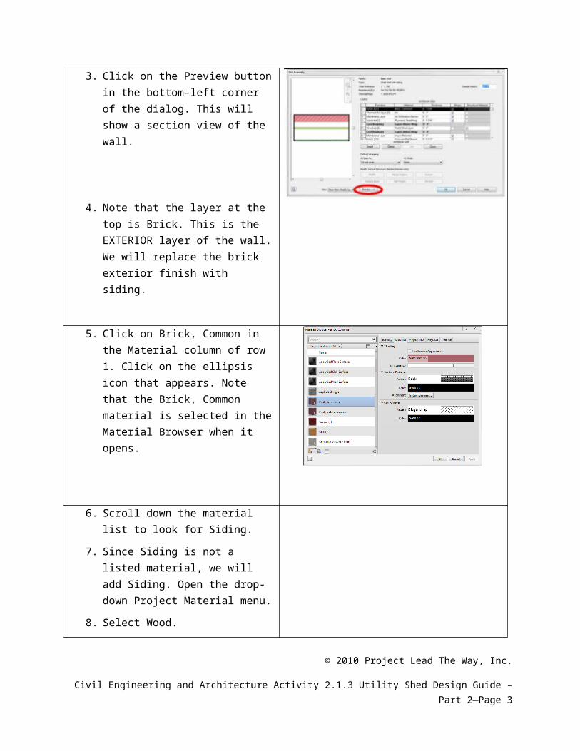
5. Click on Brick, Common in the Material column of row 1. Click on the ellipsis icon that appears. Note that the Brick, Common material is selected in the Material Browser when it opens.
6. Scroll down the material list to look for Siding.
7. Since Siding is not a listed material, we will add Siding. Open the drop-down Project Material menu.
8. Select Wood.
9. Select Plywood, Sheathing from the material list since it is the material that most closely resembles siding.
10. Duplicate the Plywood material by opening the Creates and Duplicates drop-down menu in the bottom-left corner of the dialog box. Then select Duplicate Selected Material. This will add a second Plywood, Sheathing material to the list of materials.
© 2010 Project Lead The Way, Inc.
Civil Engineering and Architecture Activity 2.1.3 Utility Shed Design Guide – Part 2—Page 3

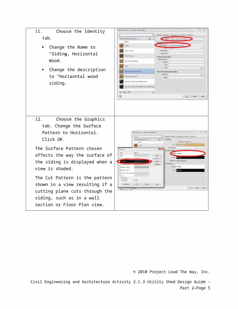
11. Choose the Identity tab.
Change the Name to “Siding, Horizontal Wood.”
Change the description to “Horizontal wood siding.”
12. Choose the Graphics tab. Change the Surface Pattern to Horizontal. Click OK.
The Surface Pattern chosen affects the way the surface of the siding is displayed when a view is shaded.
The Cut Pattern is the pattern shown in a view resulting if a cutting plane cuts through the siding, such as in a wall section or Floor Plan view.
© 2010 Project Lead The Way, Inc.
Civil Engineering and Architecture Activity 2.1.3 Utility Shed Design Guide – Part 2—Page 4
13. Choose the Appearance tab.
14. Open the Asset Browser by clicking on the icon in the lower-left corner of the Material Browser dialog box.
15. Expand the Appearance Library.
16. Open the Siding folder.
17. Select Wood—Horizontal Cedar from the list of siding choices.
18. Click on the small icon to replace the current wood image with the siding image in the editor.
Note that the image changes in the Material Browser.
19. Click OK in the Material Browser.
More material property settings are presented under the Physical and Thermal tabs. Explore these tabs. Information displayed under the Physical tab relates to properties that are important to structural design. Information displayed under the Thermal tab relates to properties that are important to energy analysis. We are not currently interested in a structural analysis or energy analysis and will therefore leave these properties as they appear (plywood properties).
© 2010 Project Lead The Way, Inc.
Civil Engineering and Architecture Activity 2.1.3 Utility Shed Design Guide – Part 2—Page 5

20. Verify that the Siding, Horizontal Wood has replaced the Brick, Common layer as the exterior layer in the Edit Assembly dialog box. (If not, click on Brick, Common in row 1, open Wood in the Project Materials drop-down menu, select Siding, Horizontal Wood from the list, and click OK.)
21. Change the thickness of the siding to ½” by replacing the existing text in the Thickness column for the siding.
22. The 3-inch air gap is not necessary in this wall configuration. Select row 2 in the Edit Assembly dialog box. Then press the Delete button.
Any other layer of the wall can be revised, replaced, or deleted in a similar manner. Additional layers can also be added when necessary. For this activity, we are finished revising the wall components.
Click OK twice.
23. Select the three walls of your shed that are currently 8” Generic walls and replace them with the new Shed Wall with Siding using the Type Selector.
© 2010 Project Lead The Way, Inc.
Civil Engineering and Architecture Activity 2.1.3 Utility Shed Design Guide – Part 2—Page 6

24. Open a 3D view of your shed. If necessary, rotate the shed so that you can see both the brick wall and one of the sided walls simultaneously. View the shed in both the shaded and the realistic visual styles.
Note the difference in the appearance. You should recognize the pattern and image displayed for the siding as the same pattern and image that you selected when you created the siding material.
Shaded Realistic
Step 12—Placing Components (Doors and Windows)
1. In Floor Plan view, select Door under the Architecture tab. In the Mode panel, click Load Family. Scroll down in the dialog box and open the Doors folder.
2. Select one of the Single-Panel door types. You will see a preview of the door type on the right. Click Open. This will load all sizes of that door type into your project.
© 2010 Project Lead The Way, Inc.
Civil Engineering and Architecture Activity 2.1.3 Utility Shed Design Guide – Part 2—Page 7

3. From the Properties Palette, change the Element Type to a single-panel (34” 80”) door from the drop-down menu.
4. Place the door in the brick wall by hovering over the wall until the door appears and then left-clicking on it. Be certain you are working in the Floor level Floor Plan.
Notice that you can change the door’s swing direction by clicking on a pair of blue arrows that appear when the door is selected. Generally an exterior door will swing into the building.
5. Repeat the above steps to load windows and add them to the model. You may choose any window type that you like. You may locate the window anywhere in your model.
Notice that you can change the orientation of a window by clicking on the pair of blue arrows that appear when the window is selected. Generally the arrows should appear on the exterior of the building.
Step 13—Revising Dimensions
Note that when you changed wall types, the 12’ exterior dimension changed. Remember that you locked the 16’ dimension, and so it remains at the locked value.
1. To revise a permanent dimension, click on a wall to which the dimension extends, click on the blue permanent dimension, and revise it to reflect the required 12’ 16’ dimensions. You may ignore the temporary dimensions that appear in this process—they will automatically update when you change the
© 2010 Project Lead The Way, Inc.
Civil Engineering and Architecture Activity 2.1.3 Utility Shed Design Guide – Part 2—Page 8

permanent dimension.
Note that the floor no longer extends to the exterior face of the wall.
2. Select the floor, and then select Edit Boundary from the Modify|Floors tab.
3. Use the Align tool in the Modify panel to align the edges of the floor to the outside face of the walls. Note that the alignment will occur at the first edge selected. Lock each alignment so that the floor edges always remain aligned to the outside faces of the walls.
4. Click the green check mark to save your edits.
Step 14—Creating a Drawing
1. In the Project Browser, right-click on Sheets. Choose New Sheet.
2. You will create a new 11” 17” sheet; however, this sheet size is not available in the dialog box. Click Load in the top-right corner of the New Sheet dialog box. The Imperial Library will appear in the Load Family dialog box.
© 2010 Project Lead The Way, Inc.
Civil Engineering and Architecture Activity 2.1.3 Utility Shed Design Guide – Part 2—Page 9

3. Scroll down and open the Titleblocks folder. Select the 11 17 titleblock and click Open. This step will load the sheet into your project.
4. To create a drawing sheet, select the B 11 17 Horizontal sheet in the New Sheet dialog box. Click Open. Click OK.
5. In the Project Browser under the parent Sheets, you will find A101—Unnamed. Right-click and rename your sheet “Green Utility Shed.” Leave the drawing number as A101.
© 2010 Project Lead The Way, Inc.
Civil Engineering and Architecture Activity 2.1.3 Utility Shed Design Guide – Part 2—Page 10

6. You may customize your titleblock. Click on the titleblock border in the graphics window, double-click on any blue text, and type the desired text.
Note that if you accidentally double-click on the titleblock, you will open edit mode for the titleblock itself. If this happens you will notice that the user interface has changed. In order to return to your project, first SAVE your project (to be sure you don’t lose any of your work) and then click on the X in the upper-right corner of the graphics window. When prompted “Do you want to save changes to B 11 x 17 Horizontal?” select No.
Step 15—Adding Required Views
1. First add your 3D view. Navigate to the 3D view (by selecting the view in the Project Browser). Use the View Cube to orient the model to show the front door in the brick wall.
2. Navigate back to the Sheet 101. In the Project Browser, left-click on the 3D view name, hold down the left mouse button, and drag the view over to the drawing sheet. Left-click again.
© 2010 Project Lead The Way, Inc.
Civil Engineering and Architecture Activity 2.1.3 Utility Shed Design Guide – Part 2—Page 11

3. Prior to clicking and dragging the floor plan onto the new sheet, navigate to the floor plan and adjust the crop box. The crop box indicates the size of the view that will be placed on the drawing. The default crop region is obviously too large for the small utility shed. Click on the Show Crop Region icon in the View Control Bar at the bottom of the screen. Then, using the blue handles, drag the four edges of the crop region close to the floor plan.
4. Turn off the crop box display by clicking on the Show Crop Box icon again. This will reduce the size of the view on the drawing sheet.
5. Finally, ensure that the view scale is ¼” = 1’-0” (a standard floor plan scale). You can change the view scale from the View Control Bar or from the Properties Palette.
© 2010 Project Lead The Way, Inc.
Civil Engineering and Architecture Activity 2.1.3 Utility Shed Design Guide – Part 2—Page 12

6. Open the new sheet view by double-clicking on the sheet name in the Project Browser.
7. Left-click on the Floor view name in the Project Browser and drag it onto Sheet A101.
8. Add two elevation views in the same way. One elevation should be the view showing the door. The other elevation view should be the view showing the wall to the right side (when looking at the front door).
Optional—Add Interior Walls
1. Add an interior wall to separate the space into two rooms.
2. Add permanent dimensions to locate the center of the interior wall from the outside face of the exterior walls.
3. Attach the top of the interior wall to the roof.
4. Add an interior door in the wall.
5. Open the 3D view and hide the roof in the view.
Helpful Hint: Note that you can hide any component in a view by selecting the component in the view, then right-clicking and selecting Hide in View.
Once you hide a component, you can unhide it by clicking on the light bulb in
© 2010 Project Lead The Way, Inc.
Civil Engineering and Architecture Activity 2.1.3 Utility Shed Design Guide – Part 2—Page 13

the View Control Bar, selecting the hidden object, right-clicking and choosing Unhide in View.
6. Now look at your drawing. The changes you made have been reflected in the drawings views.
Optional—Add Site Components
7. Open the Site Plan.
8. Add some trees to the site.
9. Load other Site or Planting components and add some additional components to your model.
10. Look at the 3D view in both Shaded and Realistic visual styles.
11. Try to add a Topo Surface to the Site plan.
12. Try to add a NEW material called Grass. It may be helpful to review the steps you took earlier to create the siding material.
13. Select Grass as the topo surface material.
© 2010 Project Lead The Way, Inc.
Civil Engineering and Architecture Activity 2.1.3 Utility Shed Design Guide – Part 2—Page 14