ACTIVE SUSPENSION TEST PLATFORM BRANDON NAYDEN & CHIAO LIU BY ADVISED BY: STEVEN GUTSCHLAG.
30
ACTIVE SUSPENSION ACTIVE SUSPENSION TEST PLATFORM TEST PLATFORM BRANDON NAYDEN & CHIAO LIU BY ADVISED BY: STEVEN GUTSCHLAG
-
date post
22-Dec-2015 -
Category
Documents
-
view
214 -
download
0
Transcript of ACTIVE SUSPENSION TEST PLATFORM BRANDON NAYDEN & CHIAO LIU BY ADVISED BY: STEVEN GUTSCHLAG.
ACTIVE SUSPENSION ACTIVE SUSPENSION TEST PLATFORMTEST PLATFORM
BRANDON NAYDEN
&
CHIAO LIU
BY
ADVISED BY: STEVEN GUTSCHLAG

TABLE OF CONTENTSTABLE OF CONTENTS PROJECT SUMMARY FUNCTIONAL DESCRIPTION SPECIFICATIONS BLOCK DIAGRAMS INPUTS/OUTPUTS EQUIPMENT/PARTS LIST DIVISION OF LABOR DISCUSSION OF
HARDWARE/SOFTWARE COMPLETED WORK QUESTIONS

PROJECT SUMMARYPROJECT SUMMARY To simulate a suspension system for
testing purposes. Actuator driven platform. Simulation for vehicular applications.

FUNCTIONAL DESCRIPTIONFUNCTIONAL DESCRIPTION A micro-controller controlled H-bridge will
dictate the movement of the actuator platform
Movement will be in a vertical fashion User input will specify desired duty cycle,
direction, and waveform Digital control feedback Liquid crystal display will indicate current
user desired output

SPECIFICATIONSSPECIFICATIONS
Platform velocity of 7 inches/second
Platform load capacity of 200 pounds
User-friendly interfaceSafe environment

FINAL PLATFORM FINAL PLATFORM CONFIGURATIONCONFIGURATION
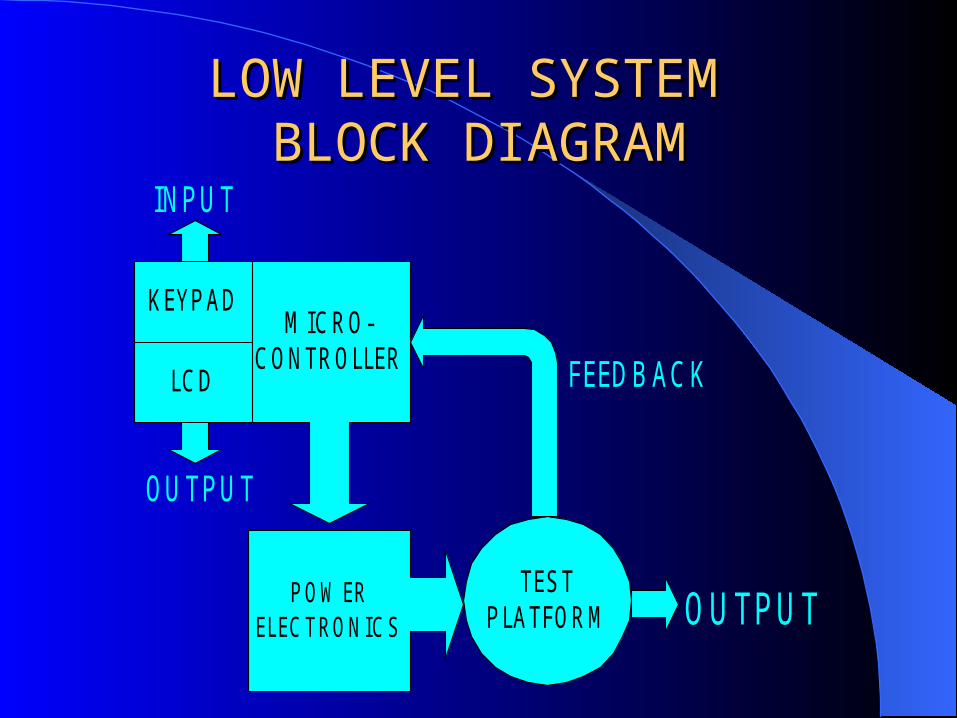
LOW LEVEL SYSTEM LOW LEVEL SYSTEM BLOCK DIAGRAMBLOCK DIAGRAM
M ICRO-CONTROLLER
KEYPAD
LCD
P OW ERELECTRONICS
TESTPLATFORM
INPUT
OUTPUT
OUTPUT
FGBHD
FEEDBACK

INPUTS/OUTPUTSINPUTS/OUTPUTS
INPUTSINPUTS Direction Duty Cycle Waveform Displacement Position
Sensor
OUTPUTS Platform
Movement Current user
input on liquid crystal display

EQUIPMENT LISTEQUIPMENT LIST(HARDWARE)(HARDWARE)
DC SERVO MOTORS IR2213 HIGH LOW DRIVERS IRF640 TRANSISTORS IRF350 TRANSISTORS 4N25 OPTICAL ISOLATORS LINEAR ACTUATOR MICRO-CONTROLLER RHEOSTAT
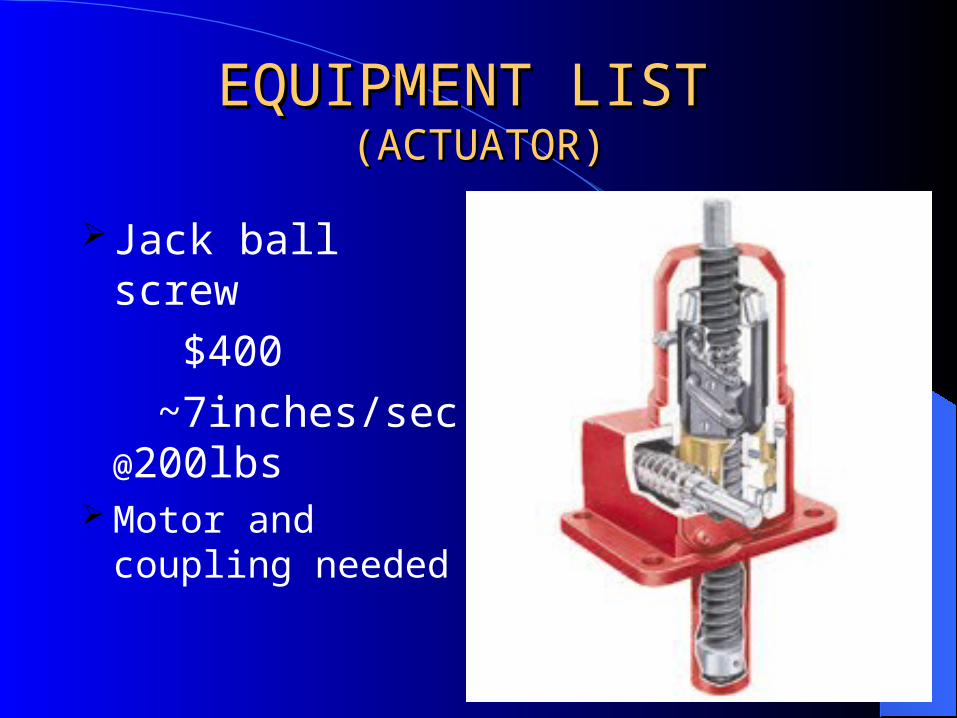
EQUIPMENT LISTEQUIPMENT LIST (ACTUATOR)(ACTUATOR)
Jack ball screw
$400
~7inches/sec @200lbs
Motor and coupling needed

DIVISION OF LABORDIVISION OF LABORChiao Liu: Micro-controller to hardware interface Protection circuitry H-bridge connections Hardware and Software debugging
Brandon Nayden: H-bridge drive circuitry All Software modules Hardware and software debugging

DISCUSSION OF HARDWAREDISCUSSION OF HARDWARE
4N25 OPTICAL
ISOLATORS
PROTECTION PURPOSE
VOLTAGE DRIVE FOR IR2213
Micro-controller
OpticalIsolator
OpticalIsolator
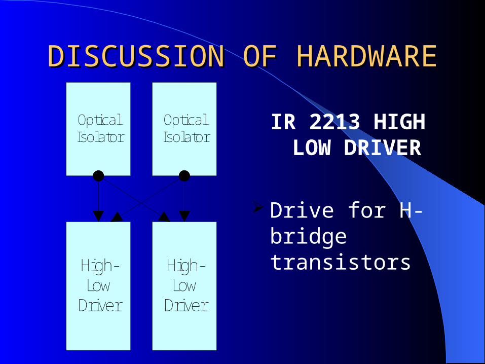
DISCUSSION OF HARDWAREDISCUSSION OF HARDWARE
IR 2213 HIGH LOW DRIVER
Drive for H-bridge transistors
OpticalIsolator
OpticalIsolator
High-LowDriver
High-LowDriver

IR2213 Combined with H-bridgeIR2213 Combined with H-bridge
Each IR2213 drives the high and low side of H-Bridge

H-Bridge and Motor DirectionH-Bridge and Motor Direction H – Bridge driven
by IR2213Forward direction of
motor

H-Bridge and Motor DirectionH-Bridge and Motor DirectionH – Bridge driven
by IR2213Reverse direction
of motor
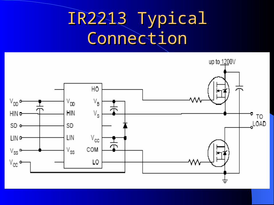
IR2213 Typical ConnectionIR2213 Typical Connection
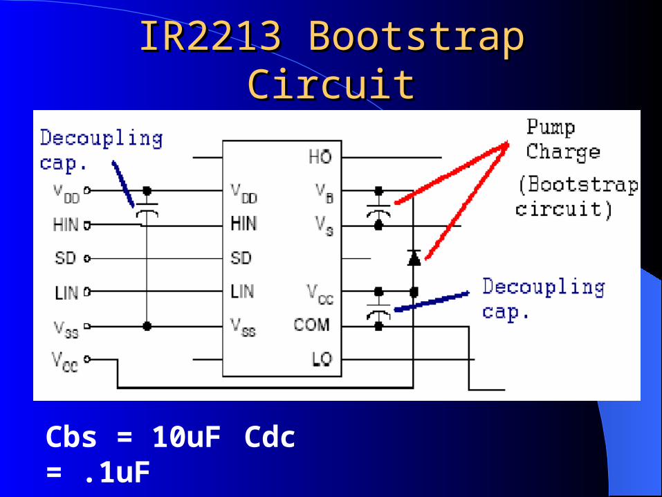
IR2213 Bootstrap CircuitIR2213 Bootstrap Circuit
Cbs = 10uF Cdc = .1uF
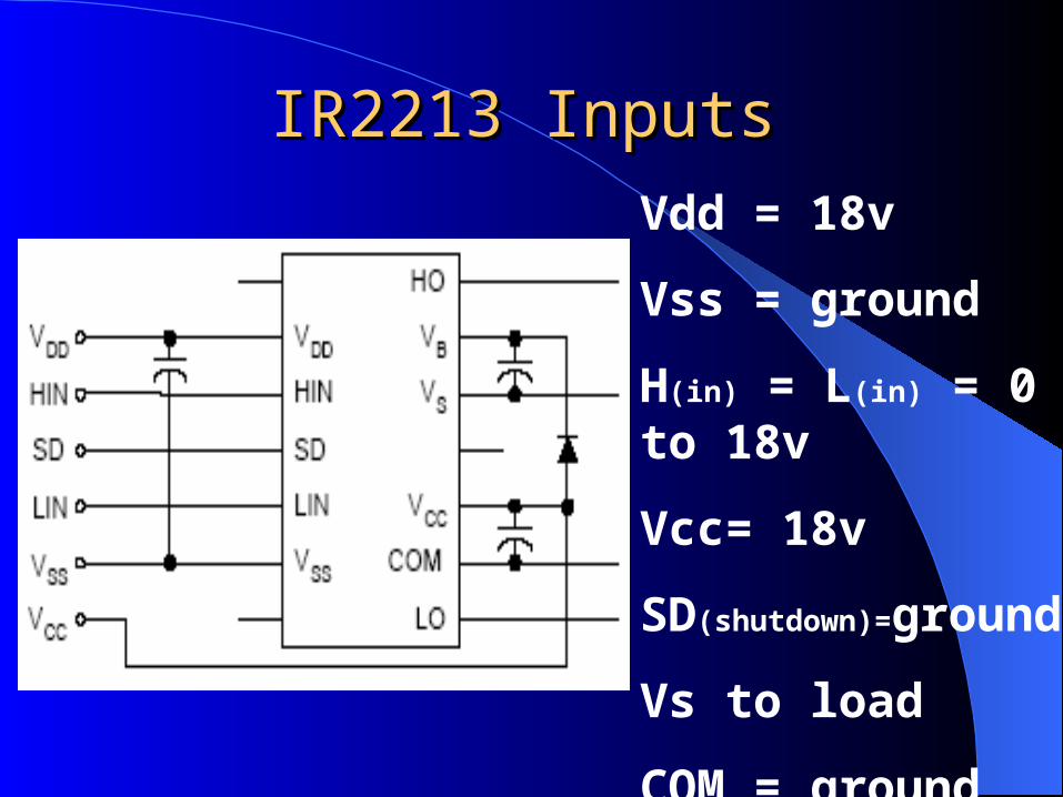
IR2213 InputsIR2213 Inputs
Vdd = 18v
Vss = ground
H(in) = L(in) = 0 to 18v
Vcc= 18v
SD(shutdown)=ground
Vs to load
COM = ground
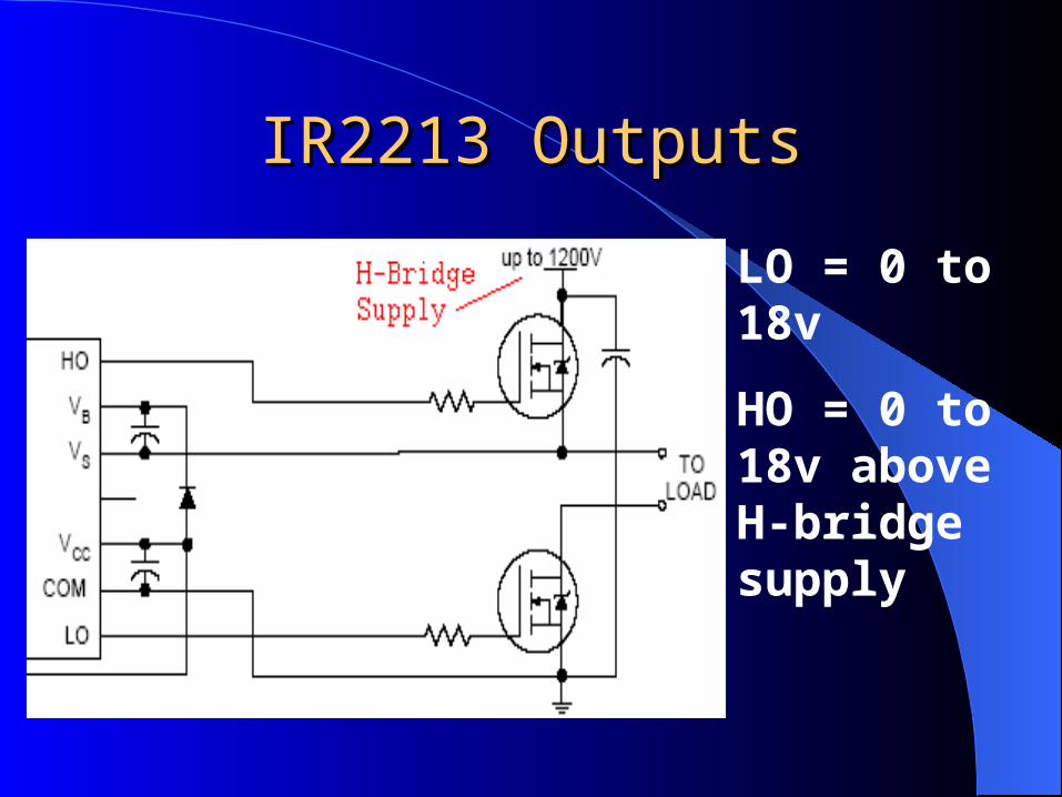
IR2213 OutputsIR2213 Outputs
LO = 0 to 18v
HO = 0 to 18v above H-bridge supply

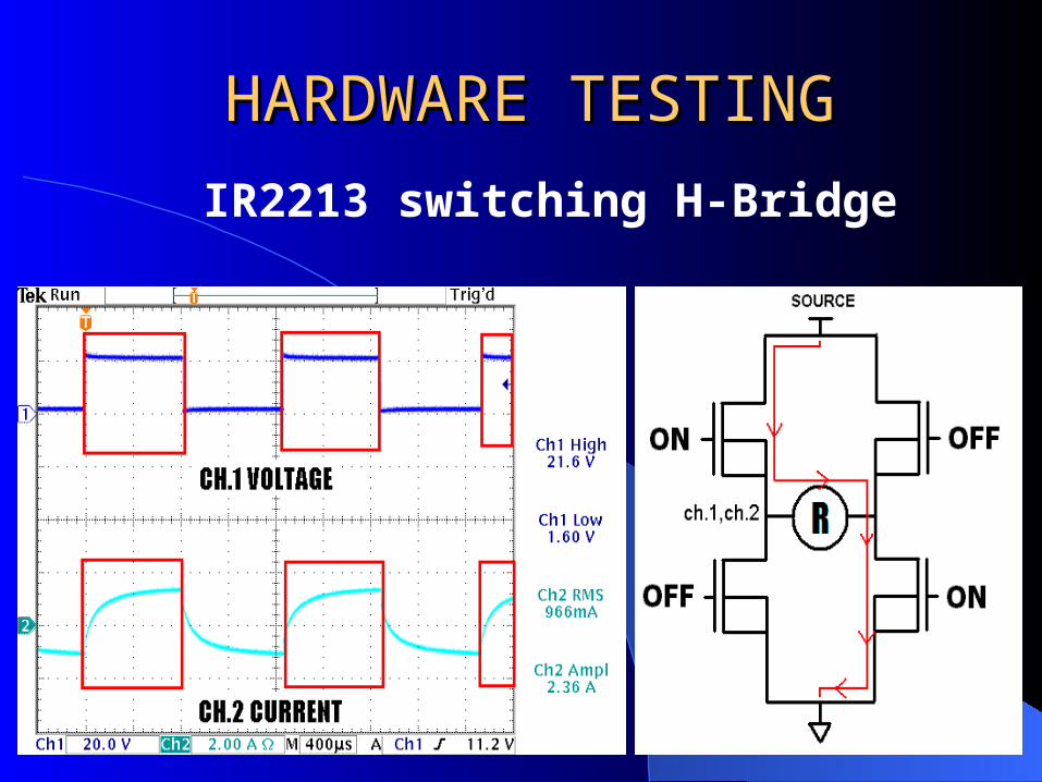
HARDWARE TESTINGHARDWARE TESTING
IR2213 switching H-Bridge
HARDWARE TESTINGHARDWARE TESTING
IR2213 switching H-Bridge
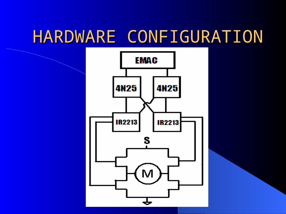
HARDWARE HARDWARE CONFIGURATIONCONFIGURATION
DISCUSSION OF HARDWAREDISCUSSION OF HARDWAREPower CalculationsPower Calculations
IRF640IRF640 120V motor 120V motor
4 amp motor rated current = 2.4 W
Without heat sink Delta T ~ 149 degrees C
With heat sink Delta T ~ 53 degrees C

SOFTWARE DISCUSSIONSOFTWARE DISCUSSION
14 ModulesTimer 2 Mode 0External interrupts for port 4 outputLiquid crystal display and keypad
implementationFeedback input from actuatorDigital control system

COMPLETED WORKCOMPLETED WORK
Searched for appropriate linear actuator and platform configuration
Searched for appropriate motor and motor drive
All hardware design and implementation Initial software design and
implementation

COMPLETED WORKCOMPLETED WORK
Bi-directional actuator movementUser interface for actuator controlDisplay of current direction and
duty cycle

COMPLETED WORKCOMPLETED WORK
Forward and reverse direction
Various duty cycles Position feedback
allows actuator to change direction without user input

TASKS ‘NOT’ COMPLETEDTASKS ‘NOT’ COMPLETED
Hardware implementation with 120 volt DC motor
Build Test Platform with appropriate linear actuator
Digital control software implementation - Ensures proper output at various loads

QUESTIONSQUESTIONS
?