Active noise control in practice: transformer station€¦ · Active noise control in practice:...
10
Inter-noise 2014 Page 1 of 10 Active noise control in practice: transformer station Edwin Buikema 1 ; Fokke D. van der Ploeg 2 ; Jan H. Granneman 3 1, 2, 3 Peutz bv, Netherlands ABSTRACT Based on literature and extensive measurements at a specific transformer two concepts regarding anti noise have been developed. These concepts have been tested in the Peutz acoustical laboratory, and on site with an experimental setup for anti noise at large transformers. Noise measurements show that a reduction of 5 dB can be achieved in all directions. Additionally, by directing the noise emission, a reduction of 10 dB can be achieved in one specific direction. This experimental project was part of a broader demonstration project regarding the practical application of different types of sensor technology. 1. INTRODUCTION From literature few examples of application of anti noise in real practical situations are available. Therefore the practical application of anti noise was introduced in the so-called “Sensor City” program. The aim of this program is to stimulate the use of sensors in a broad scope (not only for sound) and in a variety of practical cases, and if possible in combination with each other. This anti noise projects fits within this research program because of the application of sensors for measuring sound and vibration. 2. AIM OF THE RESEARCH The aim of this specific research was to obtain an understanding into the effects of anti noise at large noise sources and at long distances by the application of specific sensor techniques. At present no commercially available anti noise systems designed especially for large transformers are known. 2.1 Noise measurements Figure 1 gives an impression of the transformer used in the test. 1 [email protected] 2 [email protected] 3 [email protected]
Transcript of Active noise control in practice: transformer station€¦ · Active noise control in practice:...

Inter-noise 2014 Page 1 of 10
Active noise control in practice: transformer station Edwin Buikema1; Fokke D. van der Ploeg 2; Jan H. Granneman3
1, 2, 3 Peutz bv, Netherlands
ABSTRACT Based on literature and extensive measurements at a specific transformer two concepts regarding
anti noise have been developed. These concepts have been tested in the Peutz acoustical laboratory, and on site with an experimental setup for anti noise at large transformers. Noise measurements show that a reduction of 5 dB can be achieved in all directions. Additionally, by directing the noise emission, a reduction of 10 dB can be achieved in one specific direction.
This experimental project was part of a broader demonstration project regarding the practical application of different types of sensor technology.
1. INTRODUCTION
From literature few examples of application of anti noise in real practical situations are available. Therefore the practical application of anti noise was introduced in the so-called “Sensor City” program. The aim of this program is to stimulate the use of sensors in a broad scope (not only for sound) and in a variety of practical cases, and if possible in combination with each other. This anti noise projects fits within this research program because of the application of sensors for measuring sound and vibration.
2. AIM OF THE RESEARCH
The aim of this specific research was to obtain an understanding into the effects of anti noise at large noise sources and at long distances by the application of specific sensor techniques.
At present no commercially available anti noise systems designed especially for large transformers are known.
2.1 Noise measurements Figure 1 gives an impression of the transformer used in the test.

Page 2 of 10 Inter-noise 2014
Page 2 of 10 Inter-noise 2014
Figure 1 – Transformer Figure 2 shows typical noise spectra of a transformer, at respectively approximately 2 m and
200 m.
Figure 2 –Measuring results: A-weighted noise spectra
At a short distance frequencies of 100 Hz and 200Hz are dominant but also the higher modes (300, 400 and 500 Hz) are clearly present. At a further distance mainly the mode of 100 Hz and – although slightly less - the 200 Hz are dominant. Because of the measurement results at further distance the focus was on reducing noise around 100 Hz.
2.2 Origin of transformer noise The main installations in transformer stations are the transformers themselves. Often so-called
three-phase-transformers are used. These consist of three coils, each fitted with an iron core. There are two major sources for transformer noise. The characteristic noise of transformers is caused by magnetostriction: the expansion and
contraction within the stacked iron core (laminates) due to the magnetic effect of alternating current flowing through the transformer coils. These extensions and contractions will occur twice during

Inter-noise 2014 Page 3 of 10
Inter-noise 2014 Page 3 of 10
each complete cycle of the alternating current flowing through the coil. This causes an audible hum. To some extent magnetostriction can be reduced by adequate transformer design, but it cannot be totally eliminated.
The other cause of noise are mechanical vibrations. This usually results from vibrations emanating from the core that are transferred to parts of the installation that are attached to it.
In general there are different ways to reduce the noise emission of transformers from a manufacturing point of view, such as:
• Reduce the flux density by increasing the amount of steel in the core. This is the most effective but also the most expensive method to reduce noise.
• Apply a suitable adhesive between the layers of, for instance, epoxy or polyurethane with a low viscosity. The basic idea behind this is to reduce the ability of movement and the extent to which the laminates can extend and contract when the core is magnetized. This is considerably less expensive but means extra effort in stacking the core. The adapted system should have some resiliency and should not be rigid. A less expensive alternative is the application of an adhesive to the edges of the laminates in the stacked core. The low viscosity is required for penetration, at least to some extent, between the sheets of laminates in the core. Thereby laminates are bond together near the edges and vibrate less when magnetized.
• Noise due to vibration caused by magnetostriction transferred to other parts of the transformer causing mechanical noise can be reduced by appropriate cushioning. Flexible mounting of components will reduce the transfer of vibrations and thereby reduce noise emission.
2.3 Anti noise The noise reducing provisions as mentioned above have limited effect on new transformers and
are not directly suitable for many of the existing transformers. Therefore anti noise is an interesting alternative to reduce the noise emission of transformers.
The principle of anti noise is to apply a second noise source near the original one, radiating noise in anti phase and with the same magnitude. Interference of the sound radiated by both sources causes reduction of the total noise emission. The amount of reduction depends on frequency and the distance between both sources. Only with a secondary source at a distance of 1/10 of the wave length a significant reduction, of approximately 10 dB, can be expected from a theoretical point of view. As a consequence, for 100 Hz the distance between both sources should be 34 cm or less. Also the noise sources should be small compared to the wavelength of interest.
In practice, most noise sources do not match with these theoretical criteria. This is especially true for transformers. Transformers are used to reduce the electrical voltage from the main transportation network (grid) to lower values before entering urban or industrial areas. A transformer is a complex noise source. Different parts of its housing radiate sound in a different way and magnitude. Also, a transformer is not small compared to the wave length of the radiated sound. So the location of speakers to produce anti noise effectively has to be selected carefully. Furthermore there are practical and important safety issues. Fans can be installed in front of the transformer to cool the oil. This is the reason no sound screen is possible in front of the transformer: it would obstruct the air flow too much. Also the top has to be open for the same reason. Loudspeakers have to be placed at a safe distance from high voltage cables to avoid electrocution. So the possibilities to apply anti noise to transformers have to be tested in practice.
3. TEST SET-UP
3.1 General Based on a close look on the noise characteristics of the specific transformer, literature study and
detailed noise measurements of a transformer two concepts of anti noise were designed. At first, both concepts were tested under laboratory conditions in the Peutz laboratory. Then the test was continued in practice at a transformer station. Because of the spectrum of the noise levels near dwellings at about 100 m distance the focus was on 100 Hz.
3.2 Laboratory tests The practical possibilities of anti noise were tested with two small loudspeakers, at short distance
from each other. Figure 3 shows the principle, figure 4 the practical set-up.

Page 4 of 10 Inter-noise 2014
Page 4 of 10 Inter-noise 2014
Figure 3 – anti noise by means of two loudspeakers at short distance from each other
Figure 4 – Test set-up with two identical loudspeakers
Both loudspeakers were connected to a computer by which frequency, phase and amplitude could
be regulated. The distance between the loudspeakers was varied, and the noise reduction was measured in three directions. The achieved noise reduction varied between 8 and 13 dB; the latter value if the loudspeakers were facing each other.
In another experiment in the laboratory vibrations were generated in a plasterboard panel by
means of an exciter. This plasterboard panel (dimensions 0.45 x 0.45 m, thickness 12.5 mm) was meant to simulate a vibrating part of the transformer. The dimension of this panel was chosen in such a way that the whole panel would vibrate in phase when excited at 100 Hz. Figure 5 shows some pictures of the laboratory test set-up.

Inter-noise 2014 Page 5 of 10
Inter-noise 2014 Page 5 of 10
Figure 5 – Laboratory test set-up with vibrating panel with exciter Both a small and a large loudspeaker were placed near this vibrating panel. Figure 6 shows the
test with the smaller loudspeaker.

Page 6 of 10 Inter-noise 2014
Page 6 of 10 Inter-noise 2014
Figure 6 – Laboratory test set-up with smaller loudspeaker From these tests it appeared that reduction of the noise emission was possible with both types of
loudspeaker, reaching the values that could be achieved theoretically. Reductions of 8 to 9 dB were measured.
The tests as described above are not adaptive. In practice, with transformer variations due to
changes in load and/or temperature influence the noise emission to the environment. So an adaptive system is required, with a unit that regulates both phase and amplitude (feed forward). A possible location of the microphone for this purpose is between the vibrating panel and the loudspeaker. The optimal location of the microphone appeared to be at the center between the vibrating panel and the loudspeaker.
4. TESTS IN PRACTICE
4.1 First concept For the purposes of the first concept, a number of small loudspeakers are applied at a distance of
approximately 30 centimeters from the loudest parts of the housing of the transformer. In figure 7 two loudspeakers are shown.
Inter-noise 2014 Page 7 of 10
Inter-noise 2014 Page 7 of 10
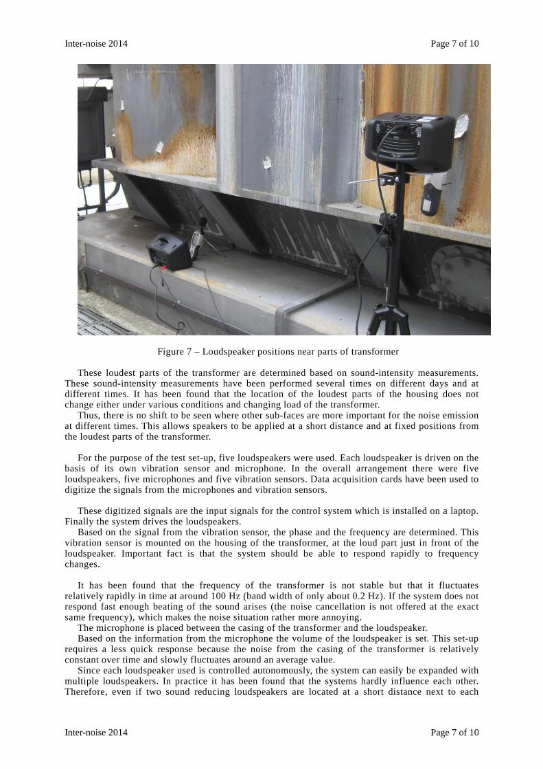
Figure 7 – Loudspeaker positions near parts of transformer These loudest parts of the transformer are determined based on sound-intensity measurements.
These sound-intensity measurements have been performed several times on different days and at different times. It has been found that the location of the loudest parts of the housing does not change either under various conditions and changing load of the transformer.
Thus, there is no shift to be seen where other sub-faces are more important for the noise emission at different times. This allows speakers to be applied at a short distance and at fixed positions from the loudest parts of the transformer.
For the purpose of the test set-up, five loudspeakers were used. Each loudspeaker is driven on the
basis of its own vibration sensor and microphone. In the overall arrangement there were five loudspeakers, five microphones and five vibration sensors. Data acquisition cards have been used to digitize the signals from the microphones and vibration sensors.
These digitized signals are the input signals for the control system which is installed on a laptop.
Finally the system drives the loudspeakers. Based on the signal from the vibration sensor, the phase and the frequency are determined. This
vibration sensor is mounted on the housing of the transformer, at the loud part just in front of the loudspeaker. Important fact is that the system should be able to respond rapidly to frequency changes.
It has been found that the frequency of the transformer is not stable but that it fluctuates
relatively rapidly in time at around 100 Hz (band width of only about 0.2 Hz). If the system does not respond fast enough beating of the sound arises (the noise cancellation is not offered at the exact same frequency), which makes the noise situation rather more annoying.
The microphone is placed between the casing of the transformer and the loudspeaker. Based on the information from the microphone the volume of the loudspeaker is set. This set-up
requires a less quick response because the noise from the casing of the transformer is relatively constant over time and slowly fluctuates around an average value.
Since each loudspeaker used is controlled autonomously, the system can easily be expanded with multiple loudspeakers. In practice it has been found that the systems hardly influence each other. Therefore, even if two sound reducing loudspeakers are located at a short distance next to each
Page 8 of 10 Inter-noise 2014
Page 8 of 10 Inter-noise 2014
other, there is no question of mutual influence and this has no effect on the overall sound reduction. In fact, if more loudspeakers are used, the final reduction will be higher.
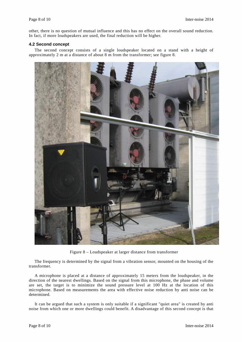
4.2 Second concept The second concept consists of a single loudspeaker located on a stand with a height of
approximately 2 m at a distance of about 8 m from the transformer; see figure 8.
Figure 8 – Loudspeaker at larger distance from transformer The frequency is determined by the signal from a vibration sensor, mounted on the housing of the
transformer. A microphone is placed at a distance of approximately 15 meters from the loudspeaker, in the
direction of the nearest dwellings. Based on the signal from this microphone, the phase and volume are set, the target is to minimize the sound pressure level at 100 Hz at the location of this microphone. Based on measurements the area with effective noise reduction by anti noise can be determined.
It can be argued that such a system is only suitable if a significant "quiet area" is created by anti
noise from which one or more dwellings could benefit. A disadvantage of this second concept is that

Inter-noise 2014 Page 9 of 10
Inter-noise 2014 Page 9 of 10
the sound level can increase at other locations.
4.3 Results With the first concept (five small loudspeakers at short distance from the transformer) the
obtained reduction at 100 Hz was 3 to 6 dB in all directions. However, more reduction is possible if more loudspeakers are used because more radiating parts of the transformer can be treated by such a system.
With the second concept (loudspeakers at further distance) an additional average reduction of 5 dB was obtained at 100 m distance.
Measurements were performed in a straight line over a distance of about 50 m with mutual
distance of approximately every 3 m; see figure 9.
Figure 9 - Dwellings at about 100 m from transformer; average effect 5 dB at 100 Hz The reductions at these positions varied between 3 to 15 dB, on average 5 dB. So reduction is
achieved in a significant area and not only at a specific point. Figure 10 shows results of anti noise.

Page 10 of 10 Inter-noise 2014
Page 10 of 10 Inter-noise 2014
Figure 10 - Results of anti noise in practice; left without anti noise, right with anti noise at 100 Hz
5. CONCLUSIONS
Anti noise creates a significant reduction of transformer noise. With the combination of both concepts (loudspeakers at short respectively longer distance from the transformer) a reduction of 10 dB at 100 Hz can be obtained at certain dwellings at about 100 m distance.
6. ACKNOWLEDGMENT
This project has been made possible by the European Union, European Fund of Regional Development, Dutch Ministry of Economical Affairs and Koers Noord as part of the project Sensor City.
A special acknowledgment to Tennet for their assistance in the practical part of this study.