ACTIVE MAGNETIC BEARINGS FOR OPTIMUM …
10
ACTIVE MAGNETIC BEARINGS FOR OPTIMUM TURBOMACHINERY DESIGN Jerry Hustak, R. Gordon Kirk, and Kenneth A. Schoeneck Ingersoll-Rand Company Phillipsburg, New Jersey 08865 The design and shop test results are given for a high speed eight stage centri- fugal compressor supported by active magnetic bearings. rotor dynamics analysis is presented with specific attention given to design consid- erations for optimum rotor stability. ings in existing machinery are discussed with supporting analysis of a four stage centrifugal compressor. ments for successful machinery operation of either retrofit or new design turbo- machinery. A brief summary of the The concerns for retrofit of magnetic bear- Recommendations are given on design and analysis require- INTRODUCTION A decade ago new technology in the form of dry gas seals was introduced into the field of industrial turbomachinery design to minimize the capital, operating, and maintenance costs associated with seal o i l systems (1). sealing system is gaining widespread recognition because it has and is continuing to demonstrate its superior mechanical, performance, and economic features in certain applications. Now once again new technology in the form of active magnetic bearings (AMB) is being introduced into the marketplace for use on individual turbomachinery. The features of this technology when applied to turbocompressor design result in several economic, performance, and versatility improvements unavailable to the in- dustry at the present time. Active magnetic bearings used in conjunction with dry gas seals and dry couplings now enable both the manufacturer and user to think in terms of oil-free centrifugal compressors, certainly a dramatic change from only ten years ago (2). Today this type of Patent activity on passive, active, and combination magnetic bearing systems spans 150 years. netic systems because they were easy to fabricate. It was later shown, however, that a passive magnetic suspension'for three axes of displacement is unstable; a theory that is still valid today. a French research firm, began investigating the characteristics of both passive and active magnetic suspension systems for a satellite flywheel application. they developed a totally active magnetic suspension system for the COMSAT comunica- tions satellite. (S2M) to further develop and commercially market active magnetic bearing (AMB) systems internationally (3,4). The bulk of the initial investigations centered on permanent mag- In 1969 Societe EuropeaMe de Propulsion (SEP), In 1970 In 1976 SEP formed a new company Societe d e Mecanique Magnetique DEVELOPMENT CENTRIFUGAL COMPRESSOR WITH AMB Figure 1 is a view of an eight stage, horizontally-split, back-to-back centri- fugal compressor equipped with magnetic radial and thrust bearings and gas seals on test at the authors' company (1980). pressor, originally designed to run at 10,000 RPM (167 Hz) on hydrodynamic bearings, The eight stage rotor housed inside the com- 327
Transcript of ACTIVE MAGNETIC BEARINGS FOR OPTIMUM …

ACTIVE MAGNETIC BEARINGS FOR OPTIMUM TURBOMACHINERY DESIGN
Jerry Hustak, R. Gordon Kirk, and Kenneth A. Schoeneck Ingersoll-Rand Company
Phillipsburg, New Jersey 08865
The design and shop test r e s u l t s are given f o r a high speed e ight s t age centri- fuga l compressor supported by active magnetic bearings. r o t o r dynamics ana lys i s is presented with spec i f i c a t t e n t i o n given t o design consid- e ra t ions f o r optimum r o t o r s t a b i l i t y . ings i n ex is t ing machinery are discussed with supporting ana lys i s of a four s t a g e cent r i fuga l compressor. ments f o r successful machinery operat ion of e i t h e r r e t r o f i t o r new design turbo- machinery.
A br ie f summary of t h e
The concerns f o r r e t r o f i t of magnetic bear-
Recommendations are given on design and ana lys i s require-
INTRODUCTION
A decade ago new technology i n t h e form of dry gas seals w a s introduced i n t o t h e f i e l d of i n d u s t r i a l turbomachinery design t o minimize t h e c a p i t a l , operat ing, and maintenance cos t s associated with seal o i l systems (1). seal ing system i s gaining widespread recogni t ion because it has and is continuing t o demonstrate its superior mechanical, performance, and economic f ea tu res i n c e r t a i n appl icat ions. Now once again new technology i n t h e form of active magnetic bearings (AMB) is being introduced i n t o the marketplace f o r u se on individual turbomachinery. The f ea tu res of t h i s technology when applied t o turbocompressor design r e s u l t i n several economic, performance, and v e r s a t i l i t y improvements unavai lable t o t h e in- dus t ry at t h e p r e s e n t time. Active magnetic bearings used i n conjunction with dry gas seals and dry couplings now enable both t h e manufacturer and use r t o th ink i n terms of o i l - f r ee cen t r i fuga l compressors, c e r t a i n l y a dramatic change from only t e n years ago (2) .
Today t h i s type of
Patent a c t i v i t y on passive, active, and combination magnetic bearing systems spans 150 years. n e t i c systems because they were easy t o fabr ica te . It was later shown, however, that a passive magnetic suspension'for three axes of displacement i s unstable; a theory t h a t is sti l l v a l i d today. a French research firm, began inves t iga t ing t h e characteristics of both passive and active magnetic suspension systems f o r a satell i te flywheel appl icat ion. they developed a t o t a l l y active magnetic suspension system f o r t h e COMSAT comunica- t i o n s satellite. (S2M) t o f u r t h e r develop and commercially market active magnetic bearing (AMB) systems in t e rna t iona l ly ( 3 , 4 ) .
The bulk of t h e i n i t i a l inves t iga t ions centered on permanent mag-
I n 1969 Societe EuropeaMe d e Propulsion (SEP),
In 1970
I n 1976 SEP formed a new company Socie te d e Mecanique Magnetique
DEVELOPMENT CENTRIFUGAL COMPRESSOR WITH AMB
Figure 1 is a view of an e ight s tage , hor izonta l ly-sp l i t , back-to-back cent r i - fugal compressor equipped with magnetic r a d i a l and t h r u s t bearings and gas seals on test at t h e authors ' company (1980). pressor, o r ig ina l ly designed t o run a t 10,000 RPM (167 Hz) on hydrodynamic bearings,
The eight s t age r o t o r housed in s ide t h e com-
327

has s ince operated successful ly a t speeds up t o 13,000 RPM (217 Hz) on magnetic bearings. purpose of operating t h e r o t o r i n a pressurized environment over a wide range of pressures and flows from choke t o surge.
The compressor is shown at tached t o two closed loops constructed f o r t he
One unique f e a t u r e of t h i s compressor w a s t h e i n s t a l l a t i o n of t h e t h r u s t and journa l bearings located on t h e f r e e end of t h e ro to r d i r e c t l y i n t o t h e gas (n i t ro - gen) pressurized environment thereby eliminating t h e need f o r one s h a f t seal. To i l l u s t r a t e t h e concept of a nonlubricated cen t r i fuga l compressor a gas seal w a s chosen as t h e main s h a f t seal on t h e coupling end of t h e ro to r . some of t h e important design f ea tu res of t h e e ight s t a g e back-to-back ro to r while Figure 2 i l l u s t r a t e s the appearance of t h e f u l l y assembled test ro to r .
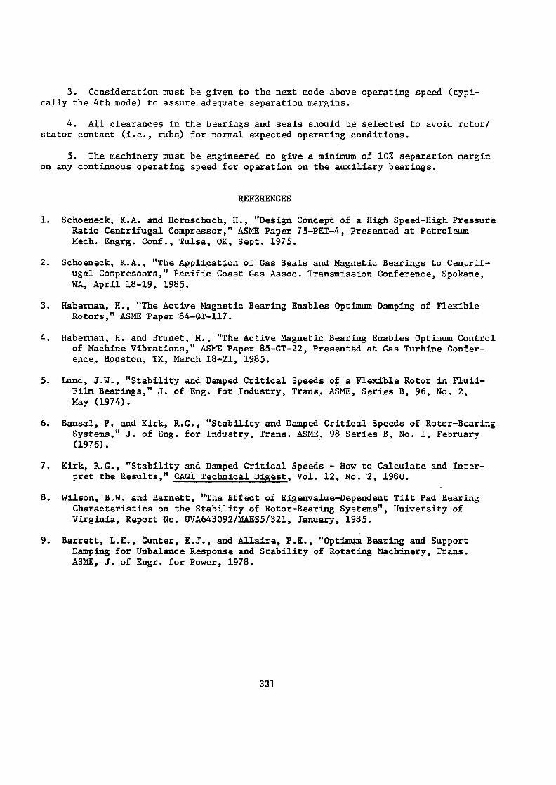
Table 1 summarizes
Before power is appl ied t o t h e bear ings t h e r o t o r is supported on two aux i l i a ry cage, dry lubr ica ted b a l l bearings located i n c lose proximity t o t h e AMB. ance between t h e ro to r and t h e inner race of t h e b a l l bearing is se lec ted t o prevent r o t o r contact with t h e AMB pole pieces o r t h e i n t e r n a l seals of t h e compressor while t h e ro to r is a t rest o r during an emergency shutdown. the AMB, i n t e r n a l seals, and aux i l i a ry bearing area are 0.012 in . ( . 3 mm), 0.010 in . (.254 mm) , and 0.006 in . (.15 mm) , respect ively. When power is applied t o t h e elec- t r o n i c cont ro ls t h e electromagnets levitate t h e ro to r i n t h e magnetic f i e l d and ro- t a t i o n of the dr iving source such as a motor or tu rb ine can be s t a r t ed . The sensors and cont ro l system regu la t e the s t r eng th and d i r e c t i o n of t h e magnetic f i e l d s t o maintain exact r o t o r pos i t i on by cont inua l ly ad jus t ing t o t h e changing forces on t h e ro to r . t h e aux i l i a ry bearings and r o t o r system are designed t o permit s a f e decelerat ion.
The clear-
Typical r a d i a l c learances i n
Should both t h e main and redundant f ea tu res of t h e AMI3 f a i l simultaneously,
The undamped critical speed map shown i n Figure 3 compares t h e standard f l u i d f i lm bear ing/o i l seal design t o t h e magnetic bearing/gas seal design f o r t h e 8 s t a g e development compressor. The magnetic bearing design increased t h e f i r s t r i g i d bear- ing mode by reducing t h e bearing span but decreased t h e second, t h i r d , and fou r th modes due t o t h e add i t iona l weight of t h e ferromagnetic j ou rna l sleeves and t h e l a rge r diameter t h r u s t co l l a r . ness and damping p rope r t i e s of t h e electromagnetic bear ings as a func t ion of r o t o r speed. have t o p a s s through t h r e e critical speeds and opera te approximately 20% above t h e t h i r d critical and 40% below t h e f o u r t h critical. and second criticals are r i g i d body modes only a s i g n i f i c a n t response at approximate- l y 8000 RPM (133 Hz) would be expected as t h e r o t o r passed through its t h i r d (free- free mode) critical. Subsequent unbalance f orced response ca l cu la t ions v e r i f i e d these expectations with acceptable operat ion of t h e compressor t o 14,000 R P M (233 Hz) (see Figures 4 and 5).
Superimposed on t h i s map are t h e as measured s t i f f -
For a design speed of 10,000 RPM (167 Hz), Figure 3 ind ica t e s t h e r o t o r would
Furthermore, since both t h e f i r s t
The damping required f o r optimum s t a b i l i t y may be a r r ived at by construct ion of
(22.8 N/pm), Figure 6 shows t h e movement of the Increased damping levels cause t h e f i r s t
The t h i r d mode increases i n s t a b i l i t y (87.7 N-sec/pm) but then decreases as damping i s in-
a Lund s t a b i l i t y map (5) from t h e ca lcu la ted damped c r i t i ca l speeds (5,6,7). 1st mode s t i f f n e s s of 130,000 l b / i n eigenvalues as t h e bearing damping varies. and second modes t o become c r i t i c a l l y damped. up t o a point of 501 lb-sec/in creased fu r the r . study w a s undertaken t o determine i f t h e t h i r d mode would go uns tab le a t i ts corre- sponding s t i f f n e s s of 229,000 l b / i n (40.1 N/llm). The r e s u l t s of that ana lys i s are presented i n Figure 7 which ind ica t e t h e t h i r d mode becomes c r i t i c a l l y damped as t h e damping is increased while t h e 1st mode damping would be a t an optimum f o r 645
For t h e
Since t h e f i r s t and second modes become c r i t i c a l l y damped, a second
328

lb-sec/in (112.9 N-sec/mm). t he increase i n bearing s t i f f n e s s , is similar t o r e s u l t s presented by Lund (5). These r e s u l t s i nd ica t e t h a t a l e v e l of 400-500 lb-sec/in be idea l f o r a l l modes up t o and including t h e fourth.
The behavior of t h e 1st and 3rd modes, r e su l t i ng from
(70-87.5 N-sec/mm) would
The a c t u a l measured s t i f f n e s s and damping characteristics f o r t h e magnetic bearing are given i n Figure 8. ence when compared t o conventional f l u i d f i lm bearings. tilt pad bearings have c h a r a c t e r i s t i c s generated predominantly by operating speed, with l i t t l e inf luence from non-synchronous exc i t a t ions (8). The active magnetic bearing characteristics, shown i n Figure 8, t a t i o n regardless of operating speed. mize unbalance forced response, t h e damping characteristics a t subsynchronous exci- t a t i o n frequencies can be spec i f ied t o assure optimum s t a b i l i t y (3, 4).
Active magnetic bearings have an important d i f f e r - Typical preloaded f i v e shoe
are dependent on t h e frequency of exci- For a given s t i f f n e s s va lue se lec ted t o mini-
The test program out l ined f o r t h e compressor w a s d i rec ted toward confirming t h e ana ly t i ca l predict ions f o r t h e dynamic behavior of t h e r o t o r and experimentally dem- ons t ra t ing t h e r e l i a b i l i t y of t h e complete system under t y p i c a l operating conditions. The f u l l y assembled compressor w a s i n s t a l l e d on t he test stand and operated a t a max- imum discharge pressure of 600 psig (4.1 MPa) with speeds up t o 13,000 R P M (217 Hz). The r e s u l t s f o r a dece l as recorded a t t h e bearing probe loca t ions are given i n Figures 9 and 10. The r e s u l t s are i n general agreement with t h e predicted unbalance forced response r e s u l t s . Since t h e amount and loca t ion of t h e a c t u a l unbalance d i s - t r i bu t ions are never known, t h e amplitude of each damped response is d i f f i c u l t t o predict . with t h e test r e s u l t s .
The predicted peak response speeds are considered t o be i n good agreement
DESIGN EVALUATION OF A FIELD RETROFIT
The economic advantages of gas seals and/or magnetic bearings has prompted in- terest i n r e t r o f i t of ex i s t ing un i t s . must be given t o placement of cri t ical speeds f o r both main and back-up bearings, response s e n s i t i v i t y , and ove ra l l s t a b i l i t y considerations. The preliminary design study f o r a 4 s t age high speed cen t r i fuga l compressor w i l l i l l u s t r a t e in more d e t a i l t h e parameters that must be considered f o r t o t a l system dynamic analysis . The bas ic design parameters f o r t h i s ro to r are indicated in t h e second column of Table 1.
For e i t h e r r e t r o f i t o r new machinery, a t t e n t i o n
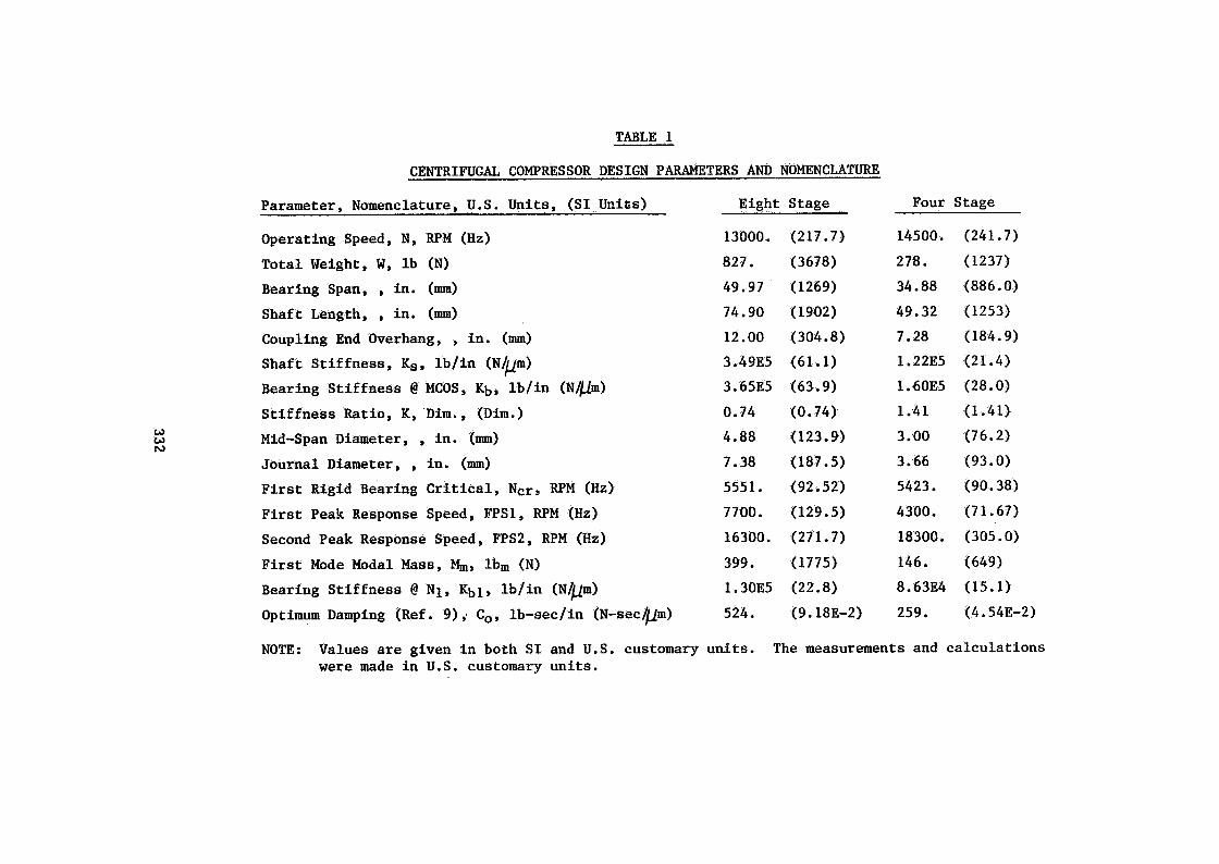
. The undamped critical speed map f o r t h e four s t age compressor with dynamic s t i f f - ness values is shown i n Figure 11. The magnetic bearing s t i f f n e s s is posit ioned such that t h e compressor must pass through t h r e e cri t ical speeds before reaching a maximum continuous operating speed of 14,500 RPM (241.7 Hz). Due t o t h e r i g i d body na ture of t h e second and t h i r d modes, t h e a c t u a l damped critical speeds w i l l occur from t h e f i r s t and fou r th modes as shown i n Figures 13 and 14 a t approximately 4300 (71.7 Hz) and 18,300 RPM (305 Hz) respect ively. constant f i r s t mode s t i f f n e s s of 86,300 l b / i n values. modes become c r i t i c a l l y damped as t h e bearing damping is increased. so r design, t h e f i r s t mode increases i n s t a b i l i t y as t h e damping increases up t o 225 lb-sec/in The damping va lue i n i t i a l l y supplied, 140 lb-sec/in (24.5 N-sec/mm), should be in- creased by 61% based on t h e r e s u l t s of t h i s ana lys i s .
Figure 15 shows t h e Lund s t a b i l i t y map using a (15.1 N/W) with v a r i a b l e damping
The f i r s t forward mode typ ica l ly goes uns tab le while t h e second and t h i r d For t h i s compres-
(39.4 N-sec/mm) but then decreases as t h e damping is increased fu r the r .
The optimum damping f o r s t a b i l i t y w a s a l s o ca lcu la ted by an approximate method
329

using the modal (see Tab le 1). high K r a t i o s ) :
m a s s , r i g i d bearing cr i t ical frequency, and ac tua l bearing s t i f f n e s s The equation from Reference (9) can be wr i t ten a s follows (val id f o r
70417.7 Kg 1.356 x lo-’ Ncr {G + N2cr
Example f o r 4-stage 1st mode:
Co = 1.356 x lo-‘ x (5423) x (146 + (70417.7) x (86300)/(542312)
= 259 lb-sec/in
This ca lcu la t ion gives an answer 15% higher than the ac tua l optimum damping f o r t h i s K r a t i o of 1.41.
Figure 16 shows a comparison of s t a b i l i t y versus aerodynamic exc i ta t ion between the conventional f l u i d f i lm design and t h e magnetic bearing r e t r o f i t design. crease i n s t a b i l i t y due t o t h e magnetic bearings moves t h e fog dec from near zero t o a value of 1.41.
The in-
CONCLUSIONS AND RECOMMENDATIONS
The capab i l i t y of an active magnetic bearing system t o support a f l e x i b l e turbo-
During t h e 350 hours of accumulated operating time f o r t h e development compressor ro tor and simultaneously inf luence its v ibra t ions has been successful ly demonstrated. compressor supported by magnetic bearings t h e following observations have been made:
1. The ro to r behaved in a s t a b l e manner a t a l l times when accelerating/deceler- a t ing through its f i r s t t h ree critical speeds.
2. The ro to r behaved i n a s t a b l e manner while undergoing surge cycles a t maxi- mum discharge pressure.
3. The ro to r w a s ab l e t o s a t i s f y commonly accepted v ibra t ion amplitude and cri t ical speed amplif icat ion criteria a t a l l operating speeds up t o 13,000 RPM (217 Hz). Speeds beyond t h i s point w e r e l imited by impeller stress considerations.
The ana lys i s of t he two compressors has c lea r ly shown t h e advantages of adjust- ab le bearing s t i f f n e s s and damping t o achieve minimum response s e n s i t i v i t y and opt i - mum s t a b i l i t y . zero t o 1.41 f o r t h e 4-stage compressor could not be accomplished by conventional f luid-f i l m bearings.
For example, t h e increase i n s t a b i l i t y from a log dec of approximately
The following recommendations can be made f o r t he design and ana lys i s of magnet- i c bearing suspension turbomachinery:
1. Bearing s t i f f n e s s should be selected by evaluation of shaft s t i f f n e s s r a t i o with typ ica l placement a t t h e beginning of t h e 3rd mode ramp on t h e undamped cr i t ical speed map.
2. Bearing damping should be specif ied t o give t h e optimum growth f ac to r s , with consideration given t o a l l modes below maximum operating speed.
330
3. Consideration must be given t o t h e next mode above operating speed ( typ i - c a l l y t h e 4 t h mode) t o assure adequate separat ion margins.
4. All clearances i n t h e bearings and seals should be se lec ted t o avoid ro to r / s t a t o r contact (i.e., rubs) f o r normal expected operating conditions.
5 . The machinery must be engineered t o g ive a minimum of 10% separat ion margin on any continuous operating speed f o r operat ion on t h e aux i l i a ry bearings.
REFERENCES
1. Schoeneck, K.A. and Hornschuch, H., "Design Concept of a High Speed-High Pressure Ratio Centrifugal Compressor," ASME Paper 75-PET-4, Presented at Petroleum Mech. Engrg. Conf., Tulsa, OK, Sept. 1975.
2. Schoeneck, K.A., "The Application of G a s Sea ls and Magnetic Bearings t o Centr i f - ugal Compressors," Pac i f i c Coast G a s Assoc. Transmission Conference, Spokane, WA, A p r i l 18-19, 1985.
3. Haberman, H., "The Active Magnetic Bearing Enables Optimum Damping of F lex ib le Rotors," ASME Paper 84-GT-117.
4. Haberman, H. and Brunet, M., "The Active Magnetic Bearing Enables Optimum Control of Machine Vibrations," ASME Paper 85-GT-22, Presented a t Gas Turbine Confer- ence, Houston, TX, March 18-21, 1985.
5. Lund, J.W., "S t ab i l i t y and Damped Critical Speeds of a Flex ib le Rotor i n Fluid- Film Bearings," J. of Eng. f o r Industry, Trans. ASME, Se r i e s B, 96, No. 2, May (1974).
6. Bansal, P. and Kirk, R.G., "S tab i l i t y and Damped Crit ical Speeds of Rotor-Bearing Systems," J. of Eng. f o r Industry, Trans. ASME, 98 Se r i e s B, No. 1, February (1976).
7. Kirk, R.G., "S tab i l i t y and Damped Critical Speeds - How t o Calculate and In t e r - p r e t t he Results," CAGI Technical Digest, Vol. 12, No. 2, 1980.
8. Wilson, B.W. and Earnet t , "The Effect of Eigenvalue-Dependent , T i l t Pad Bearing Charac te r i s t ics on the S t a b i l i t y of Rotor-Bearing Systems", University of Virginia, Report No. UVA643092/MAES5/321, January, 1985.
9. Barrett, L.E., Gunter, E.J., and Allaire, P.E., "Optimum Bearing and Support Damping f o r Unbalance Response and S t a b i l i t y of Rotating Machinery, Trans. ASME, J. of Engr. f o r Power, 1978.
331
al M
a U
m & 3
0
F
a, M
a
U
m U
d
w 5
n
v)
w
d
s H m v * m
U
d
0 3
v! 3 al &
1
U
a
rl 0
8 k4 6 . &
al U
al
d 2 PI
n
h
+
* N
W
0 0
VI 2
n
h
h
+
N
W
0 0 0
m
+
n
;
W
E L
0
a al
al a
m L
2 0" d
U
a &
PI
n
h
m
N
+
W
m
h
N
n
m
h
\o
m
W
h
N
m
n
z W
5 L
B L
U
d
%I
PI
(d
U
8
n
0
\o
m
m
W
m
m
U
m
n
m
\o
N d
W
h
m m U
W
1 E: d L
L
9 2 a
m
d
I.I a
al m
n
m
VI N
d
v
N
m
m U
n
N 0
m d
W
0
m U
h
1 W d 9 8 $
d L
L
M
4
U
tu a
n
m
u- 2
W
00 N
h
n
m
8 W
0 0
N
+
1 W d d L
L
M
c a al 3 0
a
W M
E
d
rl a
1
0
U
E a
n
* N
+
W
m W
N
N d
n
d
d
\o
W
m
w
m
m
9
n
0
m
N
W
m w
0
\o
d
n
o\
m
\o
W
VI w VI \o
m
n
\ 3 z E
d
W
n
+
9
4
W
+
9
d
n
U
h
0
W
* h 0 h
i! n
d .rf W
*
d
El
s 0
d .)
L
3 m
W
al 0
w
tu d
U
m
n
N
\o
h
W
0
0
m
n
m
N
Q: +
W
m
m
U
3 W G
d I.)
.. &
al U
al
a
d
e n
3 s a
m I c
n
0
PI m W
\o
\o
m
n
VI I-
m
+
W
m
m
h
1 W 0
d L
L
&
a)
U
al
d
rl
a c & 1
d n
n
m
m 0
m
W
m
N
U
VI
n
N
m
N
m
W
+
tr) m m
h
L4 W E .)
&
z" L
rl
a U 1-I U
d
&
U
2 d
& a al m 3 M
d
PG U
m
&
d
F
n
I-
\o
+
h
W
0
0
m
U
n
m m
N
d
W
0 0
h
h
n
L4 W
E L
+
m
PI
h
a a,
a) a
m
a 0 a
m L
2 d 24 a
al P
I U
m
&
d
k
4
n
0
VI 0
m
W
0 0
m 2
n
h
d
h
N
W
0 0
m
4
n
2 E W
p:
N
m P
I F
a a,
al a
r/J
al ).)
L
9 a m
2 $ 8 al
PI a 0
al m
n
m
+
d
W
U w m
\o
03
n
m
N
N
W
VI w 0
m
+
n
N I
w
* m
* W m
VI N
n
N
I w 2
a
W
U
N
m
n
e a 25
0
al m
W
332

EG 0
E-r 0
d W
2 $l E-r X
W H
W
ORIG
INAL PAGE IS
OF PO
OR Q
UA
LITY
D
w n
N
W
e4 B H
Er
3 3 0 H
F
m
w
333


OF PO
OR Q
UA
LfTY
0
rl 335
U
d
cr) d
336

![Analytical Model of the Magnetic Field Distribution of a ...the development of wind turbine technology [4,5]. Magnetic bearings are high-performance bearings that use magnetic force](https://static.fdocuments.in/doc/165x107/5f6b57be6d584621194538d4/analytical-model-of-the-magnetic-field-distribution-of-a-the-development-of.jpg)