active front end (afe) arfiff02 application...
88
vacon nx ac drives active front end (afe) arfiff02 application manual ®
Transcript of active front end (afe) arfiff02 application...

vacon nxac drives
active front end (afe)arfiff02
application manual
®


vacon • 1
TABLE OF CONTENTS
Document: DPD000905BSoftware code: ARFIFF02V148
Release date : 21/2/17
1. Introduction .....................................................................................................32. AFE units..........................................................................................................42.1 500 Vac units Air Cooled ....................................................................................................42.2 690 Vac units Air Cooled ....................................................................................................52.3 500 Vac units Liquid-Cooled ..............................................................................................62.4 690 Vac units Liquid-Cooled ..............................................................................................73. Operation .........................................................................................................83.1 Main contactor control.......................................................................................................83.2 Quick Start instructions .....................................................................................................94. CONTROL IO ...................................................................................................125. AFE Application - Monitoring values ..............................................................145.1 Monitoring values.............................................................................................................155.1.1 Monitoring 1 .....................................................................................................................155.1.2 Monitoring values 2..........................................................................................................165.1.3 FieldBus Monitoring values .............................................................................................165.1.4 IO Monitoring values ........................................................................................................165.1.5 Unit Monitoring Values.....................................................................................................175.1.6 Monitoring 1 values..........................................................................................................175.1.7 Monitoring 2 values..........................................................................................................195.1.8 Fieldbus monitoring values .............................................................................................195.1.9 IO Monitoring values ........................................................................................................275.1.10 Unit Monitoring values .....................................................................................................286. AFE Application - Parameter lists..................................................................296.1 Basic parameters.............................................................................................................306.2 Reference Handling .........................................................................................................316.3 Input signals.....................................................................................................................326.3.1 Digital inputs ....................................................................................................................326.3.2 Analogue inputs ...............................................................................................................336.4 Output signals ..................................................................................................................346.4.1 Digital Outputs .................................................................................................................346.4.2 Analogue Output 1............................................................................................................356.5 Limit Settings ...................................................................................................................366.5.1 Current Limit....................................................................................................................366.5.2 Power Limit ......................................................................................................................366.5.3 Auto Start Stop .................................................................................................................366.5.4 DC Voltage........................................................................................................................366.6 Drive Control parameters ................................................................................................376.7 Control parameters .........................................................................................................386.8 Fieldbus parameters........................................................................................................396.9 Protections .......................................................................................................................406.9.1 General .............................................................................................................................406.9.2 PT-100 ..............................................................................................................................416.9.3 Earth fault ........................................................................................................................416.9.4 Fieldbus............................................................................................................................416.10 Auto reset parameters.....................................................................................................426.11 DIN ID Control ..................................................................................................................426.12 Keypad control .................................................................................................................426.13 System menu ...................................................................................................................426.14 Expander boards ..............................................................................................................42
Local contacts: http://drives.danfoss.com/danfoss-drives/local-contacts/
vacon • 2
7. Description of parameters .............................................................................437.1 Basic parameters.............................................................................................................437.2 Reference Handling .........................................................................................................447.3 Input signals.....................................................................................................................467.3.1 Digital inputs ....................................................................................................................467.3.2 Analogue Inputs ...............................................................................................................497.4 Output signals ..................................................................................................................507.4.1 Digital outputs ..................................................................................................................507.4.2 Analogue outputs .............................................................................................................507.5 Limit settings ...................................................................................................................527.5.1 Current Limits..................................................................................................................527.5.2 Power Limits ....................................................................................................................527.5.3 Auto Start Stop function...................................................................................................527.5.4 DC Voltage limit parameters ...........................................................................................537.6 Drive control.....................................................................................................................547.6.1 Drive control.....................................................................................................................567.7 Fieldbus parameters........................................................................................................587.8 Protections .......................................................................................................................597.8.1 PT100 Temperature .........................................................................................................607.8.2 Earth fault ........................................................................................................................617.8.3 Fieldbus............................................................................................................................627.9 Auto restart ......................................................................................................................637.10 DIN ID Control ..................................................................................................................647.11 Keypad control .................................................................................................................648. Fieldbus Profile for VACON® Regenerative Drive .........................................658.1 Signals from Overriding System to VACON® regenerative Drive...................................658.2 Signals from VACON® Drive to Overriding system.........................................................658.3 Main Control Word ...........................................................................................................668.4 FB Reference Control ......................................................................................................678.5 Main Control Word (in DeviceNet) ...................................................................................688.6 Main Status Word.............................................................................................................708.7 Fault Word 1 .....................................................................................................................728.8 Fault Word 2 .....................................................................................................................728.9 Warning Word 1................................................................................................................738.10 Auxiliary Control Word.....................................................................................................748.11 Auxiliary Control Word (in DeviceNet) .............................................................................758.12 FB Reference Control (Device net) ..................................................................................768.13 Aux Status Word ID 1163.................................................................................................778.14 Status Word (Application) ID 43 ......................................................................................789. Fault codes.....................................................................................................80
Local contacts: http://drives.danfoss.com/danfoss-drives/local-contacts/

Introduction vacon • 3
Local contacts: http://drives.danfoss.com/danfoss-drives/local-contacts/1
1. INTRODUCTION
The AFE unit is a regenerative power converter for the front-end of a common DC bus product line.
The AFE unit is used with inverter hardware and special software. An external L(CL)-filter and charging circuit is needed. This unit is selected when low harmonics are required. The connection of AFE drive has been described in Figure .
The Regenerative Application is easy and flexible to use due to its versatile fieldbus features. The parameters of the Regenerative Application are explained in Chapter 8.
The basic I/O-configuration of the AFE drive consists of OPT-A1 and OPT-A2 option cards. The basic I/O configuration has been described in Table 5. An option card OPT-B5 can be used if additional digital outputs are needed. Configuration has been described in Table 6.
By default the control place (P3.1) of the AFE drive is keypad.
This application requires NXP control board 661 or 761.
Figure 1. AFE connection
11280.emf

2
vacon • 4 AFE units
2. AFE UNITS
2.1 500 Vac units Air Cooled
Table 1. 500 Vac units Air Cooled
Unit
Code Enclosure size IL-cont [A] IH-cont [A]
NXA_0168 5 A0T02SF 1xFI9 170 140
NXA_0205 5 A0T02SF 1xFI9 205 170
NXA_0261 5 A0T02SF 1xFI9 261 205
NXA_0385 5 A0T02SF 1xF10 385 300
NXA_0460 5 A0T02SF 1xFI10 460 385
NXA_1150 5 A0T02SF 1xFI13 1150 1030
NXA_1300 5 A0T02SF 1xFI13 1300 1150
Local contacts: http://drives.danfoss.com/danfoss-drives/local-contacts/

AFE units vacon • 5
2.2 690 Vac units Air Cooled
Table 2. 690 Vac units Air Cooled
Unit
Code Enclosure size IL-cont [A] IH-cont [A]
NXA_0125 6 A0T02SF 1xFI9 125 100
NXA_0144 6 A0T02SF 1xFI9 144 125
NXA_0170 6 A0T02SF 1xFI9 170 144
NXA_0261 6 A0T02SF 1xFI10 261 208
NXA_0325 6 A0T02SF 1xFI10 325 261
NXA_0920 6 A0T02SF 1xFI13 920 820
NXA_1030 6 A0T02SF 1xFI13 1030 920
Local contacts: http://drives.danfoss.com/danfoss-drives/local-contacts/2

2
vacon • 6 AFE units
2.3 500 Vac units Liquid-Cooled
Table 3. 500 Vac units Liquid-Cooled
Unit
Code Chassis Ith-cont [A] IL-cont [A] IH-cont [A]
NXA01685A0T02WS CH5 168 153 112
NXA02055A0T02WS CH5 205 186 137
NXA02615A0T02WS CH5 261 237 174
NXA03005A0T02WF CH61 300 273 200
NXA03855A0T02WF CH61 385 350 257
NXA04605A0T02WF CH62 460 418 307
NXA05205A0T02WF CH62 520 473 347
NXA05905A0T02WF CH62 590 536 393
NXA06505A0T02WF CH62 650 591 433
NXA07305A0T02WF CH62 730 664 487
NXA08205A0T02WF CH63 820 745 547
NXA09205A0T02WF CH63 920 836 613
NXA10305A0T02WF CH63 1030 936 687
NXA11505A0T02WF CH63 1150 1045 767
NXA13705A0T02WF CH64 1370 1245 913
NXA16405A0T02WF CH64 1640 1491 1093
NXA20605A0T02WF CH64 2060 1873 1373
NXA23005A0T02WF CH64 2300 2091 1533
Local contacts: http://drives.danfoss.com/danfoss-drives/local-contacts/

AFE units vacon • 7
2.4 690 Vac units Liquid-Cooled
Table 4. 690 Vac units Liquid-Cooled
Unit
Code Chassis Ith-cont [A] IL-cont [A] IH-cont [A]
NXA01706A0T02WF CH61 170 155 113
NXA02086A0T02WF CH61 208 189 139
NXA02616A0T02WF CH61 261 237 174
NXA03256A0T02WF CH62 325 295 217
NXA03856A0T02WF CH62 385 350 257
NXA04166A0T02WF CH62 416 378 277
NXA04606A0T02WF CH62 460 418 307
NXA05026A0T02WF CH62 502 456 335
NXA05906A0T02WF CH63 590 536 393
NXA06506A0T02WF CH63 650 591 433
NXA07506A0T02WF CH63 750 682 500
NXA08206A0T02WF CH64 820 745 547
NXA09206A0T02WF CH64 920 836 613
NXA10306A0T02WF CH64 1030 936 687
NXA11806A0T02WF CH64 1180 1073 787
NXA13006A0T02WF CH64 1300 1182 867
NXA15006A0T02WF CH64 1500 1364 1000
NXA17006A0T02WF CH64 1700 1545 1133
Local contacts: http://drives.danfoss.com/danfoss-drives/local-contacts/2
3
vacon • 8 Operation
3. OPERATION
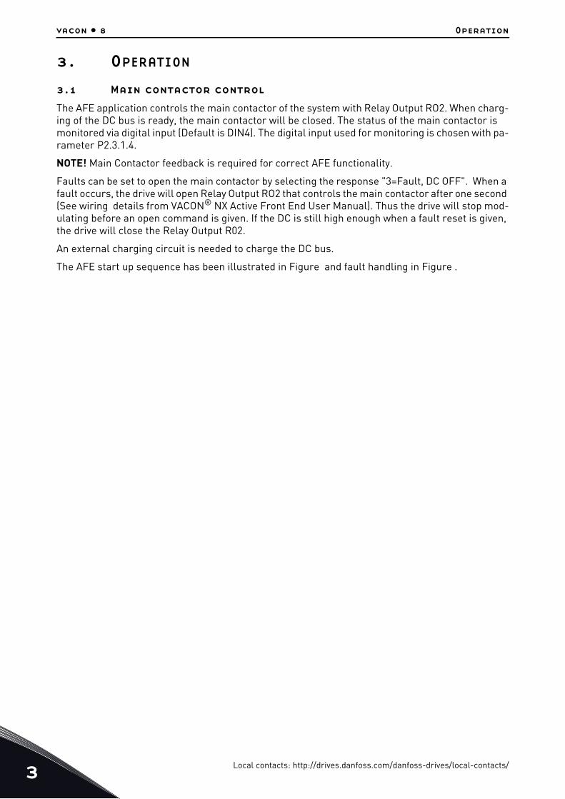
3.1 Main contactor control
The AFE application controls the main contactor of the system with Relay Output RO2. When charg-ing of the DC bus is ready, the main contactor will be closed. The status of the main contactor is monitored via digital input (Default is DIN4). The digital input used for monitoring is chosen with pa-rameter P2.3.1.4.
NOTE! Main Contactor feedback is required for correct AFE functionality.
Faults can be set to open the main contactor by selecting the response "3=Fault, DC OFF". When a fault occurs, the drive will open Relay Output RO2 that controls the main contactor after one second (See wiring details from VACON® NX Active Front End User Manual). Thus the drive will stop mod-ulating before an open command is given. If the DC is still high enough when a fault reset is given, the drive will close the Relay Output R02.
An external charging circuit is needed to charge the DC bus.
The AFE start up sequence has been illustrated in Figure and fault handling in Figure .
Local contacts: http://drives.danfoss.com/danfoss-drives/local-contacts/

Operation vacon • 9
3.2 Quick Start instructions
NOTE! Before taking any commissioning actions, read carefully the safety instructions in VACON® NXS/P User Manual.
1. Connect the unit according to Figure .2. Power up the control unit3. Set Basic parameters G2.1 (see Table 21). 4. Check that the digital input parameters (P2.3.1.1 - P2.3.1.10) have been set according to con-
nections. All the unused input signals must be set to "0 = Not used" state, except for the main contactor feedback which must be used.
5. Change the control place to I/O (P3.1).6. Precharge the unit.
In case of parallel AFE:
1. Set the Parallel AFE parameter (P2.1.4) = YES (in every AFE). (This will set also DC Drooping to 4.00%)
2. Set the Start Up Delay in AFE units so that starting is in sequence with e.g. 500 ms intervals.Figure 2.
Figure 3.Setting the Start Up Delay in AFE units
Time * 500 ms
StopAFE 1
Run
StopAFE 2
Run
StopAFE 3
Run
StopAFE 4
Run
11281.emf
Local contacts: http://drives.danfoss.com/danfoss-drives/local-contacts/3
3
vacon • 10 Operation
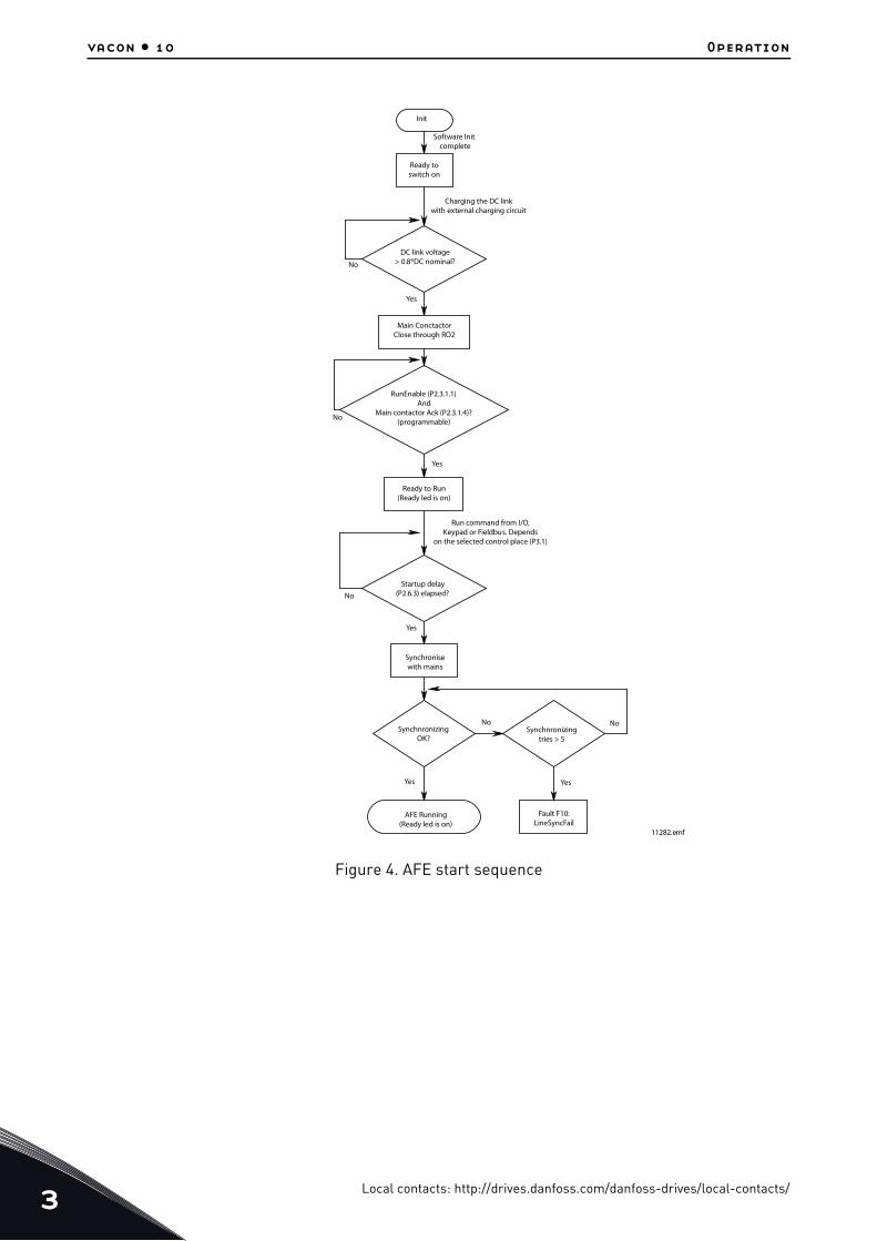
Figure 4. AFE start sequence
Init
Software Initcomplete
11282.emf
Ready toswitch on
Charging the DC linkwith external charging circuit
DC link voltage> 0.8*DC nominal?No
No
No
No No
Yes
Yes
Yes
Yes Yes
Main ConctactorClose through RO2
RunEnable (P2.3.1.1)And
Main contactor Ack (P2.3.1.4)?(programmable)
Ready to Run(Ready led is on)
Run command from I/O,Keypad or Fieldbus. Depends
on the selected control place (P3.1)
Startup delay(P2.6.3) elapsed?
Synchronisewith mains
SynchnronizingOK?
Synchnronizingtries > 5
AFE Running(Ready led is on)
Fault F10:LineSyncFail
Local contacts: http://drives.danfoss.com/danfoss-drives/local-contacts/

Operation vacon • 11
Figure 5.Fault handling in AFE application11284.emf
AFE Running
Fault active
Stop the AFE
Is responseMain contactor
open?Yes
No
Fault acknowledge
Main contactoropen
Main contactorclose
Faultacknowledge
Local contacts: http://drives.danfoss.com/danfoss-drives/local-contacts/3

4
vacon • 12 CONTROL IO
4. CONTROL IO
Table 5. Default I/O configuration
K1
NXOPTA1
NXOPTA2
Terminal Signal Description
1 +10 Vref Reference voltege output
2 AI1+Analogue input 1.•Range 0-10V, Ri= 200 ΩRange 0-20 nA, Ri= 250Ω
Analogue input 2.•Range 0-10V, Ri= 200Ω•Range 0-20 nA, Ri= 250Ω
3 AI1- I/O ground
4 AI2+
5 AI2-
6 +24V
7 GND I/O ground
8 DIN1 Contact closed = Start Request
9 DIN2
10 DIN3
11 CMA Common for DIN 1—DIN 3
12 +24V
13 GND I/O ground
14 DIN4 Contact closed = MCC Closed
15 DIN5
16 DIN6 Rising edge will reset•active faults.
17 CMB
18 AOA1+ Output range selected by jumpers.Range 0—20 mA. RL, max. 500ΩRange 0—10 V. RL > 1kΩ19 AOA1-
20
21
22
23
DOA1 Digital outputReady / Warning (Blinking)
mA
9429_uk
Voltege for•potentiometer, etc.Analogue input 1Input rangeselected by jumpers.Default range: Voltage 0–10 VGround for referenceand controls
Ground for referenceand controls
Analogue input 2Input range selected byjumpers.Default range:•Current 0 – 20 mAVoltage for switches, etc.max 0.1 A
Start RequestProgrammable G2.3.1
Programmable G2.3.1
Programmable P2.3.1
No function defined at default
No function defined at default
No function defined at default
Connect to GND or +24V
Voltage for switches (see #6)
Ground for reference andcontrols
Main Contactor AcknowledgeProgrammable G2.2.1
Fault ResetProgrammable G2.3.1
Connect to GND or +24V
Analogue output 1Programmable G2.3.1
ProgrammableOpen collector, I≤50mA,U≤48 VDC
RO 1
RO 1
RO 1
24
25
26
RO 2
RO 2
RO 2
Relay output 1Run State
Programmable G2.4.2
Relay output 2Main Contactor Control
Cannot be reprogrammedG2.4.1
Switchin capacity24 VCD / 8 A250 VAC / 8 A125 VDC / 0.4 A
Fixed to main contactorcontrol.Closes when DC at 80 % ofnominal DC.Opens when DC below 75 %•of nominal DC
220
VAC
K1
Control voltage output
Programmable G2.3.1
Common for DIN4—DIN6
Local contacts: http://drives.danfoss.com/danfoss-drives/local-contacts/

CONTROL IO vacon • 13
The default I/O configuration if the option card PT-B5 is used:
Table 6. Default I/O configuration
OPT-B5
22
23
25
9430_uk
RO 1•common
RO 2•common
RO 3•common
RO 1 NO
26
28
29
RO 2
RO 3
Relay output 1Fault
Relay output 2Warning
Relay output 3Temperature warning
Switching capacity 24VDC/8A•250VAC/8A•125VDC/0.4A
Switching capacity 24VDC/8A•250VAC/8A•125VDC/0.4A
Switching capacity 24VDC/8A•250VAC/8A•125VDC/0.4A
Local contacts: http://drives.danfoss.com/danfoss-drives/local-contacts/4

5
vacon • 14 AFE Application - Monitoring values
5. AFE APPLICATION - MONITORING VALUES
This chapter presents the lists of parameters within the respective parameter groups.
Column explanations
The manual presents the signals that are not normally visible for monitoring. These are not param-eters or standard monitoring signals. These signals are presented with [Letter], e.g. [FW]Motor-RegulatorStatus.
Code = Location indication on the keypad; shows the operator the present parameter number
Parameter = Name of the parameter
Min = Minimum value of the parameter
Max = Maximum value of the parameter
Unit = Unit of the parameter value; given if available
Default = Value preset by factory
Cust = Customer's own setting
ID = ID number of the parameter
[V] Normal monitoring signal
[P] Normal parameter in application.
[FW] Firmware signal, can be monitored with NCDrive when signal type Firmware is selected
[A] Application signal, can be monitored with NCDrive when signal type Application is selected
[R] Reference type parameter on keypad.
[F] Function. Signal is received as an output of function.
[DI] Digital input signal.
Local contacts: http://drives.danfoss.com/danfoss-drives/local-contacts/

AFE Application - Monitoring values vacon • 15
5.1 Monitoring values
The monitoring values are actual values of parameters and signals as well as statuses and mea-surements. Monitoring values cannot be edited.
5.1.1 Monitoring 1
Table 7. Monitoring 1
Code Signal Unit ID Description
V1.1.1 DC Voltage V 1108 Measured DC Link voltage in Volts
V1.1.2Used DC Voltage
Reference% 1200
Used DC voltage reference by the regenerative unit in percentage of Nominal DC Voltage. Nominal DC voltage = 1.35 * Supply voltage
V1.1.3 Total Current A 1104Total current of the regenerative unit in Amperes.
V1.1.4 Active Current % 1125
Reactive current of the regenerative drive in percentage of Rated Line Current. > 0 power from AC side to DC side< 0 power from DC side to AC side
V1.1.5 Reactive Current % 1157
Reactive current of the regenerative drive in percentage of Rated Line Current.> 0 Inductive current< 0 Capacitive current
V1.1.6 Active Power kW 1511> 0 power from AC side to DC side< 0 power from DC side to AC side
V1.1.7 Power % % 5> 0 power from AC side to DC side< 0 power from DC side to AC side
V1.1.8 Status Word 43
V1.1.9 Supply Frequency Hz 1101Supply frequency in ##.## Hz. The sign indicates the phase order.
V1.1.10 Supply Voltage V 1107Input AC voltage, RMS line to line Volts.
V1.1.11 Line Frequency D7 Hz 1654 Measured line frequency by OPT-D7
V1.1.12 Line Voltage D7 V 1650 Measured line voltage by OPT-D7
V1.1.13 D7 Synch.Error 1659Signed phase difference compared to measurement with optD7 card (-3072...3071) = -180...180deg
Local contacts: http://drives.danfoss.com/danfoss-drives/local-contacts/5
5
vacon • 16 AFE Application - Monitoring values
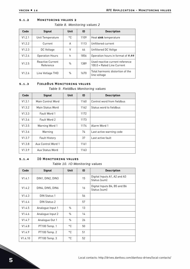
5.1.2 Monitoring values 2
5.1.3 FieldBus Monitoring values
5.1.4 IO Monitoring values
Table 8. Monitoring values 2
Code Signal Unit ID Description
V1.2.1 Unit Temperature °C 1109 Heat sink temperature
V1.2.2 Current A 1113 Unfiltered current
V1.2.3 DC Voltage V 44 Unfiltered DC Voltge
V1.2.4 Operation Hours h 1856 Operation hours in format of #,##
V1.2.5Reactive Current
Reference% 1389
Used reactive current reference 100.0 = Rated Line Current
V1.2.6 Line Votlage THD % 1670Total harmonic distortion of the line voltage
Table 9. FieldBus Monitoring values
Code Signal Unit ID Description
V1.3.1 Main Control Word 1160 Control word from fieldbus
V1.3.2 Main Status Word 1162 Status word to fieldbus
V1.3.3 Fault Word 1 1172
V1.3.4 Fault Word 2 1173
V1.3.5 Warning Word 1 1174 Alarm Word 1
V1.3.6 Warning 74 Last active warning code
V1.3.7 Fault History 37 Last active fault
V1.3.8 Aux Control Word 1 1161
V1.3.9 Aux Status Word 1163
Table 10. IO Monitoring values
Code Signal Unit ID Description
V1.4.1 DIN1, DIN2, DIN3 15Digital Inputs A1, A2 and A3 Status (sum)
V1.4.2 DIN4, DIN5, DIN6 16Digital Inputs B4, B5 and B6 Status (sum)
V1.4.3 DIN Status 1 56
V1.4.4 DIN Status 2 57
V1.4.5 Analogue Input 1 % 13
V1.4.6 Analogue Input 2 % 14
V1.4.7 Analogue Out 1 % 26
V1.4.8 PT100 Temp. 1 °C 50
V1.4.9 PT100 Temp. 2 °C 51
V1.4.10 PT100 Temp. 3 °C 52
Local contacts: http://drives.danfoss.com/danfoss-drives/local-contacts/

AFE Application - Monitoring values vacon • 17
5.1.5 Unit Monitoring Values
5.1.6 Monitoring 1 values
V1.1.1 DC-LINK VOLTAGE [# V] ID 1108
Measured DC voltage, filtered.
V1.1.2 USED DC VOLTAGE REFERENCE [#,## %] ID 1200
Used DC voltage reference by the regenerative unit in percentage of Nominal DC Voltage.
Nominal DC Voltage = Supply Voltage * 1.35
DC Voltge = Supply Voltage * 1.35 * Boost
e.g.
621 Vdc = 400 Vac * 1.35 * 1.15
V1.1.3 TOTAL CURRENT [A] ID 1104
Total current of the regenerative unit in Amperes, filtered.
V1.1.4 ACTIVE CURRENT [#,# %] ID 1125
Active current in percentage of System Rated Current. A negative value means that the current isflowing to AC side from DC side i.e. regenerating.
V1.1.5 REACTIVE CURRENT [#,# %] ID 1157
Reactive current of the regenerative drive in percentage of System Rated Current.
Positive value means Inductive current.
Negative value means capacitive current.
V1.1.6 POWER KW [KW] ID 1511
Drive output power in kW.
V1.4.11 DO1, RO1, RO2 17Digital Output and Relay 1&2 Status (sum)
Table 11. Unit Monitoring Values
Code Signal Unit ID Description
V1.5.1 Unit Nominal Voltage V 1117 Unit rated AC Voltage
V1.5.2 Unit Nominal Current A 1118
V1.5.3 U Phase Current A 1149 U Phase RMS current
V1.5.4 V Phase Current A 1150 V Phase RMS current
V1.5.5 W Phase Current A 1151 W Phase RMS current
Table 10. IO Monitoring values
Code Signal Unit ID Description
Local contacts: http://drives.danfoss.com/danfoss-drives/local-contacts/5

5
vacon • 18 AFE Application - Monitoring values
A negative value means that current is flowing to AC side from DC side i.e. regenerating.
V1.1.7 POWER % [#,# %] ID 5
Drive output power in percentage.
A negative value means that current is flowing to AC side from DC side i.e. regenerating.
V1.1.8 STATUS WORD (APPLICATION) ID 43
Application Status Word combines different drive statuses to one data word.
V1.1.9 SUPPLY FREQUENCY [#,## HZ] ID 1101
Supply frequency in ##.## Hz .The sign indicates the phase order. Updated when the drive is in runstate. Updated also in stop state when OPT-D7 is used or Regen Options B9 is activated.
V1.1.10 SUPPLY VOLTAGE [#,# V] ID 1107
Input AC voltage, RMS line to line Volts. Updated when the drive is in run state.
Updated also when OPT-D7 is used.
V1.1.11 LINE FREQUENCY [#,## HZ] ID 1654
Measured Line Voltage Frequency when using OPT-D7 option board in slot C.
V1.1.12 LINE VOLTAGE [# V] ID 1650
Measured line voltage rms value when using OPT-D7 option board in slot C.
V1.1.13 D7 SYNCH ERROR [# V] ID 1659
Table 12. Application Status Word
FALSE TRUE
b0
b1 Not in Ready state Ready
b2 Not Running Running
b3 No Fault Fault
b4 Positive frequency Negative frequency
b5 No fault or AutoResetFault Fault or Auto Reset Fault
b6 Run Disabled Run Enable
b7 No Warning Warning
b8 Charging Switch closed (internal)
b9 Main Contactor Control (DO Final)
b10 Main Contactor Feedback
b11
b12 No Run Request Run Request
b13 Motoring Side Generator Side
b14 F1, F31 or F41 active
b15
Local contacts: http://drives.danfoss.com/danfoss-drives/local-contacts/
AFE Application - Monitoring values vacon • 19
Voltage angle error between OPT-D7 line voltage and AFE unit voltage. If error is not close to zerowhen in run state phase order of OPT-D7 may be wrong.
5.1.7 Monitoring 2 values
V1.2.1 UNIT TEMPERATURE [# °C] ID 1109
Temperature of the unit in degrees Celsius.
V1.2.2 CURRENT [A] ID 1113
Unfiltered current of the drive.
V1.2.3 DC VOLTAGE [# V] ID 44
Unfiltered DC Voltage.
V1.2.4 OPERATION HOURS [#,## H] ID1856
This shows operation hours of the drive. P2.6.7 is used to enter the old value if software is updated.
V1.2.5 REACTIVE CURRENT REFERENCE [#,# %] ID1389
Used reactive current reference 100.0 = Rated Line Current.
Positive value means Inductive current.
Negative value means capacitive current.
V1.2.6 LINE VOLTAGE THD ID1670
OPT-D7 measured line voltage THD.
5.1.8 Fieldbus monitoring values
V1.3.1 MAIN CONTROL WORD ID 1160
Control word from fieldbus. The table below is for the bypass operation for such fieldbus board thatnatively supports this or can be parameterized to bypass mode.
Local contacts: http://drives.danfoss.com/danfoss-drives/local-contacts/5

5
vacon • 20 AFE Application - Monitoring values
Table 13. Main Control Word
FALSE TRUE
b0 DC charge Contactor close 0= No Action1= Close DC charge contactor
b1 OFF2 =Stop0=stop Active. Regenerative control is stopped.1=stop not active
b2 Reserved for future use.
b3 Run 0= Drive stop command1= Drive start command
b4 Reserved for future use.
b5 Reserved for future use.
b6 Reserved for future use.
b7 Reset 0>1 Reset fault.
b8 Set DC Voltage Ref 1 DC Voltage Reference 1, see details in Chapter 8.4 "FB Reference Control".
b9 Set DC Voltage Ref 2 DC Voltage Reference 2, see details in Chapter 8.4 "FB Reference Control".
b10 Fieldbus Control 0= No control from fieldbus1=Control from fieldbus
b11 Watchdog
0>1>0>1…1 sec square wave clock. This is used to check the data com-munication between fieldbus master and the drive. Used to generate FB Comm. Fault. This monitoring can be switched off by setting P2.8.4.2 FB Watchdog Delay=0. The drive’s inter-nal communication monitoring is still active at this time.
b12 Reserved for future use.
b13 Reserved for future use.
b14 Reserved for future use.
b15 Reserved for future use.
Local contacts: http://drives.danfoss.com/danfoss-drives/local-contacts/
AFE Application - Monitoring values vacon • 21
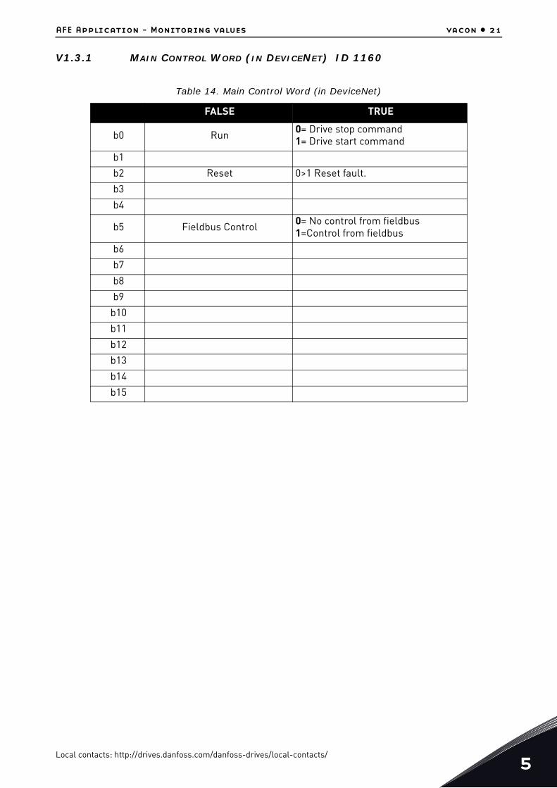
V1.3.1 MAIN CONTROL WORD (IN DEVICENET) ID 1160
Table 14. Main Control Word (in DeviceNet)
FALSE TRUE
b0 Run 0= Drive stop command1= Drive start command
b1
b2 Reset 0>1 Reset fault.
b3
b4
b5 Fieldbus Control 0= No control from fieldbus1=Control from fieldbus
b6
b7
b8
b9
b10
b11
b12
b13
b14
b15
Local contacts: http://drives.danfoss.com/danfoss-drives/local-contacts/5
5
vacon • 22 AFE Application - Monitoring values
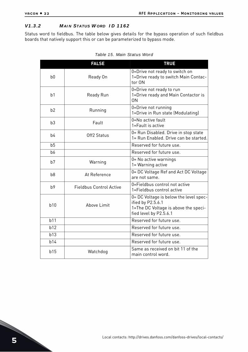
V1.3.2 MAIN STATUS WORD ID 1162
Status word to fieldbus. The table below gives details for the bypass operation of such fieldbusboards that natively support this or can be parameterized to bypass mode.
Table 15. Main Status Word
FALSE TRUE
b0 Ready On0=Drive not ready to switch on1=Drive ready to switch Main Contac-tor ON
b1 Ready Run0=Drive not ready to run1=Drive ready and Main Contactor is ON
b2 Running 0=Drive not running1=Drive in Run state (Modulating)
b3 Fault 0=No active fault 1=Fault is active
b4 Off2 Status 0= Run Disabled. Drive in stop state 1= Run Enabled. Drive can be started.
b5 Reserved for future use.
b6 Reserved for future use.
b7 Warning 0= No active warnings1= Warning active
b8 At Reference 0= DC Voltage Ref and Act DC Voltage are not same.
b9 Fieldbus Control Active 0=Fieldbus control not active1=Fieldbus control active
b10 Above Limit
0= DC Voltage is below the level spec-ified by P2.5.6.1 1=The DC Voltage is above the speci-fied level by P2.5.6.1
b11 Reserved for future use.
b12 Reserved for future use.
b13 Reserved for future use.
b14 Reserved for future use.
b15 Watchdog Same as received on bit 11 of the main control word.
Local contacts: http://drives.danfoss.com/danfoss-drives/local-contacts/

AFE Application - Monitoring values vacon • 23
V1.3.3 FAULT WORD 1 ID 1172
V1.3.4 FAULT WORD 2 ID 1173
Table 16. Fault Word 1
FALSE TRUE
b0 Over Current F1
b1 Overvoltage F2
b2 Under voltage F9
b3 Not used
b4 Earth Fault F3
b5 Not used
b6 Unit Over Temperature F14
b7 Over Temperature F59, F56, F71
b8 Input Phase loss F11
b9 Not used
b10 Device Fault F37, F38, F39, F40, F44, F45
b11 Not used
b12 Not used
b13 Not used
b14 Not used
b15 Not used
Table 17. Fault Word 2
FALSE TRUE
b0 Not used
b1 Charging Switch Fault F5
b2 Not used
b3 Drive Hardware fault F4, F7
b4 Under Temperature F13
b5 EPROM or Checksum fault F22
b6 External fault F51
b7 Not used
b8 Internal Communication F25
b9 IGBT Temperature F31, F41
b10 Not used
b11 Cooling fan F32, F70
b12 Application fault F35
b13 Drive Internal fault F33, F36, F8, F26
b14 Main Switch open F64
b15 Not used
Local contacts: http://drives.danfoss.com/danfoss-drives/local-contacts/5
5
vacon • 24 AFE Application - Monitoring values
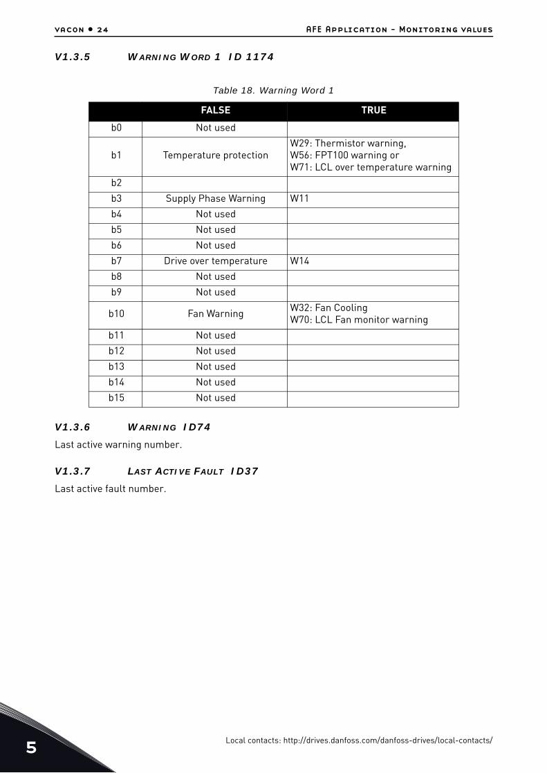
V1.3.5 WARNING WORD 1 ID 1174
V1.3.6 WARNING ID74
Last active warning number.
V1.3.7 LAST ACTIVE FAULT ID37
Last active fault number.
Table 18. Warning Word 1
FALSE TRUE
b0 Not used
b1 Temperature protectionW29: Thermistor warning,W56: FPT100 warning orW71: LCL over temperature warning
b2
b3 Supply Phase Warning W11
b4 Not used
b5 Not used
b6 Not used
b7 Drive over temperature W14
b8 Not used
b9 Not used
b10 Fan Warning W32: Fan CoolingW70: LCL Fan monitor warning
b11 Not used
b12 Not used
b13 Not used
b14 Not used
b15 Not used
Local contacts: http://drives.danfoss.com/danfoss-drives/local-contacts/

AFE Application - Monitoring values vacon • 25
V1.3.8 AUX CONTROL WORD ID 1161
Table 19. Aux Control Word
FALSE TRUE
b0 Reserved for future use.
b1 Reserved for future use.
b2 Reserved for future use.
b3 Reserved for future use.
b4 Reserved for future use.
b5 Reserved for future use.
b6 Reserved for future use.
b7 Reserved for future use.
b8 Reserved for future use.
b9 Reserved for future use.
b10 Reserved for future use.
b11 Reserved for future use.
b12 Enable DC Level control from MCW
0= DC Voltage Level control from Main Control Word (MCW) is not active and DC Voltage reference is from fieldbus data (reference value). 1= DC Voltage Level control from MCW is enabled
b13 DO control This signal can be connected to digi-tal output with parameters in G2.4.1
b14 Reserved for future use.
b15 Reserved for future use.
Local contacts: http://drives.danfoss.com/danfoss-drives/local-contacts/5

5
vacon • 26 AFE Application - Monitoring values
V1.3.8 AUX CONTROL WORD (IN DEVICE NET) ID 1161
V1.3.9 AUX STATUS WORD ID 1163
Reserved for future use.
Table 20. Auxiliary Control Word (in DeviceNet)
FALSE TRUE
b0 DC charge Contactor close 0= No Action1= Close DC charge contactor
b1 OFF2 =Stop0=stop Active. Regenerative control is stopped.1=stop not active
b2 Set DC Voltage Ref 1DC Voltage Reference 1. For details, see Chapter 8.4 "FB Reference Con-trol".
b3 Set DC Voltage Ref 2DC Voltage Reference 2, see detail from Chapter 8.4 "FB Reference Con-trol".
b4 Watchdog
0>1>0>1…1 sec square wave clock. This is used to check data communi-cation between fieldbus master and the drive. Used to generate FB Comm. Fault. This monitoring can be switched off by setting P2.8.4.2 FB Watchdog Delay=0. The drive’s inter-nal communication monitoring is still active at this time.
b5 Reserved for future use.
b6 Reserved for future use.
b7 Reserved for future use.
b8 Reserved for future use.
b9 Reserved for future use.
b10 Reserved for future use.
b11 Reserved for future use.
b12 Enable DC Level control from MCW
0= DC Voltage Level control from Main Control Word (MCW) is not active and DC Voltage reference is from fieldbus data (reference value). 1= DC Voltage Level control from MCW is enabled
b13 DO control This signal can be connected to digi-tal output with parameters in G2.4.1
b14 Reserved for future use.
b15 Reserved for future use.
Local contacts: http://drives.danfoss.com/danfoss-drives/local-contacts/

AFE Application - Monitoring values vacon • 27
5.1.9 IO Monitoring values
V1.4.1 DIN1, DIN2, DIN3 ID 15V1.4.2 DIN4, DIN5, DIN6 ID 16
V1.4.3 DIN STATUS 1 ID 56V1.4.4 DIN STATUS 2 ID 57
V1.4.5 ANALOGUE INPUT 1 [#,## %] ID13V1.4.6 ANALOGUE INPUT 2 [#,## %] ID14
Unfiltered analogue input level.
0% = 0 mA / 0 V, -100% = -10 V, 100% = 20 mA / 10 V.
Monitoring scaling is determined by the option board parameter.
V1.4.7 ANALOGUE OUT 1 [#,## %] ID 26
Analogue Output value 0% = 0 mA / 0 V, 100% = 20 mA / 10 V.
DIN1/DIN2/DIN3 status DIN4/DIN5/DIN6 status
b0 DIN3 DIN6
b1 DIN2 DIN5
b2 DIN1 DIN4
DIN Status Word 1 DIN Status Word 2
b0 DIN: A.1 DIN: C.5
b1 DIN: A.2 DIN: C.6
b2 DIN: A.3 DIN: D.1
b3 DIN: A.4 DIN: D.2
b4 DIN: A.5 DIN: D.3
b5 DIN: A.6 DIN: D.4
b6 DIN: B.1 DIN: D.5
b7 DIN: B.2 DIN: D.6
b8 DIN: B.3 DIN: E.1
b9 DIN: B.4 DIN: E.2
b10 DIN: B.5 DIN: E.3
b11 DIN: B.6 DIN: E.4
b12 DIN: C.1 DIN: E.5
b13 DIN: C.2 DIN: E.6
b14 DIN: C.3
b15 DIN: C.4
Local contacts: http://drives.danfoss.com/danfoss-drives/local-contacts/5

5
vacon • 28 AFE Application - Monitoring values
V1.4.8 PT100 TEMP. 1 [#,# °C] ID 50V1.4.9 PT100 TEMP. 2 [#,# °C] ID 51V1.4.10 PT100 TEMP. 3 [#,# °C] ID 52
Separate measurement from PT100 board. The signal has 4 s filtering time.
V1.4.11 DO1, RO1, RO2 ID 17
Digital Output and Relay 1&2 Status (sum).
5.1.10 Unit Monitoring values
V1.5.1 UNIT NOMINAL VOLTAGE [# V] ID 1117
Unit rated AC voltage in volts.
V1.5.2 UNIT NOMINAL CURRENT [A] ID 1118
Nominal current rating of the converter in Amperes. Unit Ih Current.
V1.5.3 U PHASE CURRENT [A] ID 1149
U Phase RMS current.
V1.5.4 V PHASE CURRENT [A] ID 1150
V Phase RMS current.
V1.5.5 W PHASE CURRENT [A] ID 1151
W Phase RMS current.
Local contacts: http://drives.danfoss.com/danfoss-drives/local-contacts/
AFE Application - Parameter lists vacon • 29
6. AFE APPLICATION - PARAMETER LISTS
This chapter presents the lists of parameters within the respective parameter groups.
Column explanations
The manual presents the signals that are not normally visible for monitoring. These are not param-eters or standard monitoring signals. These signals are presented with [Letter], e.g. [FW]Motor-RegulatorStatus.
Code = Location indication on the keypad; shows the operator the present parameter number
Parameter = Name of the parameter
Min = Minimum value of the parameter
Max = Maximum value of the parameter
Unit = Unit of the parameter value; given if available
Default = Value preset by factory
Cust = Customer's own setting
ID = ID number of the parameter
[V] Normal monitoring signal
[P] Normal parameter in application.
[FW] Firmware signal, can be monitored with NCDrive when signal type Firmware is selected
[A] Application signal, can be monitored with NCDrive when signal type Application is selected
[R] Reference type parameter on keypad.
[F] Function. Signal is received as an output of function.
[DI] Digital input signal.
Local contacts: http://drives.danfoss.com/danfoss-drives/local-contacts/6
6
vacon • 30 AFE Application - Parameter lists
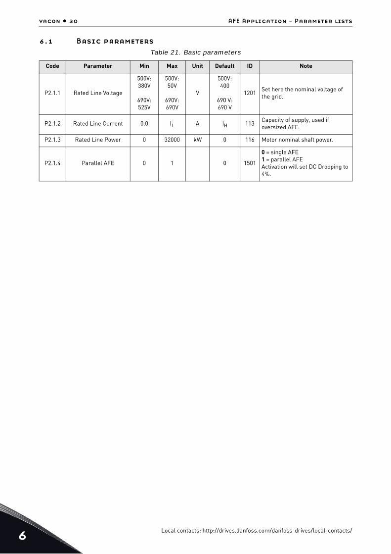
6.1 Basic parameters
Table 21. Basic parameters
Code Parameter Min Max Unit Default ID Note
P2.1.1 Rated Line Voltage
500V:380V
690V:525V
500V:50V
690V:690V
V
500V:400
690 V:690 V
1201Set here the nominal voltage of the grid.
P2.1.2 Rated Line Current 0.0 IL A IH 113Capacity of supply, used if oversized AFE.
P2.1.3 Rated Line Power 0 32000 kW 0 116 Motor nominal shaft power.
P2.1.4 Parallel AFE 0 1 0 1501
0 = single AFE1 = parallel AFEActivation will set DC Drooping to 4%.
Local contacts: http://drives.danfoss.com/danfoss-drives/local-contacts/
AFE Application - Parameter lists vacon • 31
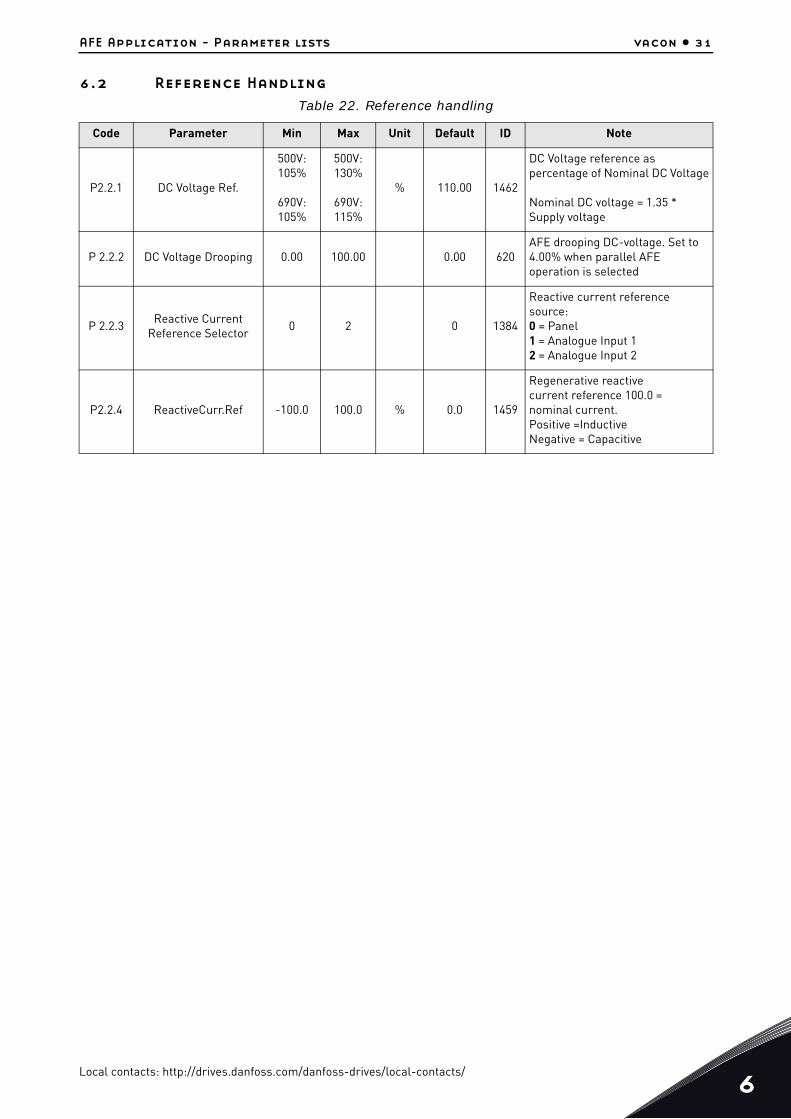
6.2 Reference Handling
Table 22. Reference handling
Code Parameter Min Max Unit Default ID Note
P2.2.1 DC Voltage Ref.
500V:105%
690V:105%
500V:130%
690V:115%
% 110.00 1462
DC Voltage reference as percentage of Nominal DC Voltage
Nominal DC voltage = 1.35 * Supply voltage
P 2.2.2 DC Voltage Drooping 0.00 100.00 0.00 620AFE drooping DC-voltage. Set to 4.00% when parallel AFE operation is selected
P 2.2.3Reactive Current
Reference Selector0 2 0 1384
Reactive current reference source:0 = Panel1 = Analogue Input 12 = Analogue Input 2
P2.2.4 ReactiveCurr.Ref -100.0 100.0 % 0.0 1459
Regenerative reactivecurrent reference 100.0 =nominal current.Positive =InductiveNegative = Capacitive
Local contacts: http://drives.danfoss.com/danfoss-drives/local-contacts/6
6
vacon • 32 AFE Application - Parameter lists
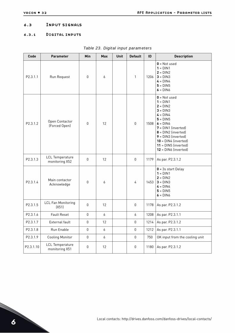
6.3 Input signals
6.3.1 Digital inputs
Table 23. Digital input parameters
Code Parameter Min Max Unit Default ID Description
P2.3.1.1 Run Request 0 6 1 1206
0 = Not used1 = DIN12 = DIN23 = DIN34 = DIN45 = DIN56 = DIN6
P2.3.1.2 Open Contactor (Forced Open)
0 12 0 1508
0 = Not used1 = DIN12 = DIN23 = DIN34 = DIN45 = DIN56 = DIN67 = DIN1 (inverted)8 = DIN2 (inverted)9 = DIN3 (inverted)10 = DIN4 (inverted)11 = DIN5 (inverted)12 = DIN6 (inverted)
P2.3.1.3LCL Temperature
monitoring X520 12 0 1179 As par. P2.3.1.2
P2.3.1.4Main contactor Acknowledge
0 6 4 1453
0 = 3s start Delay1 = DIN12 = DIN23 = DIN34 = DIN45 = DIN56 = DIN6
P2.3.1.5LCL Fan Monitoring
(X51)0 12 0 1178 As par. P2.3.1.2
P2.3.1.6 Fault Reset 0 6 6 1208 As par. P2.3.1.1
P2.3.1.7 External fault 0 12 0 1214 As par. P2.3.1.2
P2.3.1.8 Run Enable 0 6 0 1212 As par. P2.3.1.1
P2.3.1.9 Cooling Monitor 0 6 0 750 OK input from the cooling unit
P2.3.1.10LCL Temperature
monitoring X510 12 0 1180 As par. P2.3.1.2
Local contacts: http://drives.danfoss.com/danfoss-drives/local-contacts/

AFE Application - Parameter lists vacon • 33
6.3.2 Analogue inputs
Table 24. Analogue input parameters
Code Parameter Min Max Unit Default ID Description
P2.3.2.1Analogue Input 1
Minimum0 1 0 1227
Minimum voltage orCurrent at AI1.
0 = 0 V / 0 A1 = 2 V / 4 mA
P2.3.2.2Analogue Input 1 Filter
Time0.00 10.00 s 1.00 1228
Filter time for AI1 in ###.## sec.0 = No filtering
P2.3.2.3Analogue Input 2
Minimum0 1 0 1231
Minimum voltage orCurrent at AI2 in.
0 = 0 V / 0 A1 = 2 V / 4 mA
P2.3.2.4Analogue Input 2 Filter
Time0.00 10.00 s 1.00 1232
Filter time for AI2 ###.## sec.0 = No filtering
Local contacts: http://drives.danfoss.com/danfoss-drives/local-contacts/6

6
vacon • 34 AFE Application - Parameter lists
6.4 Output signals
6.4.1 Digital Outputs
Table 25. Digital output parameters
Code Parameter Min Max Unit Default ID Description
P2.4.1.1Digital output 1
function0 11 9 1216
Signal selection for DO1.0 = DO Control from FB (AuxControlWord, bit 13) 1 = Ready2 = Running3 = Fault4 = No Fault5 = Warning6 = At Reference7 = Regen Active8 = Charge DC9 = Ready / Warning (blink).10 = Temperature Warning.11 = DC Voltage Above Limit
P2.4.1.2Relay Output 1
function0 11 2 1217
Signal selection for the digital indication through RO1.
P2.4.1.3Relay Output 2
function0 0 0 1218
Main Contactor ControlSlot B, Output 2This parameter cannot be changed.
P2.4.1.4 DO4 0 11 3 1385 Digital Output 4 function
P2.4.1.5 DO5 0 11 5 1386 Digital Output 5 function
P2.4.1.6 DO6 0 11 10 1390 Digital Output 6 function
P2.4.1.7 DO7 0 11 0 1391 Digital Output 7 function
P2.4.1.8 DO8 0 11 0 1395 Digital Output 8 function
P2.4.1.9 DO9 0 11 0 1396 Digital Output 9 function
P2.4.1.10 DO10 0 11 0 1423 Digital Output 10 function
P2.4.1.11 DO11 0 11 0 1427 Digital Output 11 function
P2.4.1.12 DO12 0 11 0 1428 Digital Output 12 function
P2.4.1.13 DO13 0 11 0 1429 Digital Output 13 function
Local contacts: http://drives.danfoss.com/danfoss-drives/local-contacts/

AFE Application - Parameter lists vacon • 35
6.4.2 Analogue Output 1
Table 26. Analog Output 1 parameters
Code Parameter Min Max Unit Default ID Description
P2.4.2.1 AO1 Signal ID 0 2000 0 1233Set the ID no. of a signal to be connected to AO1.
P2.4.2.2 AO1 Offset 0 1 0 1234
Minimum voltage or current at AO1. 0= OV/0mA.1= 2V/4mA
P2.4.2.3 AO1 Filter 0.02 10.00 s 10.00 1235 Filter time for AO1 in ##.## sec.
P2.4.2.4 AO1 Max Value -30000 30000 1500 1236Maximum value of a signal connected to AO1. This will correspond to +10V/20mA.
P2.4.2.5 AO1 Min Value -30000 30000 0 1237
Minimum value of a signal connected to AO1. This will correspond to 0V/0mA or 2V/4mA depending on the AO1 Offset
Local contacts: http://drives.danfoss.com/danfoss-drives/local-contacts/6

6
vacon • 36 AFE Application - Parameter lists
6.5 Limit Settings
6.5.1 Current Limit
6.5.2 Power Limit
6.5.3 Auto Start Stop
6.5.4 DC Voltage
Table 27. Current Limit
Code Parameter Min Max Unit Default ID Description
P2.5.1.1 Current Limit 0 Varies A IL 107 Total current limit
Table 28. Power Limit
Code Parameter Min Max Unit Default ID Description
P 2.5.2.1Power Limit Motoring
Side0 300 % 300 1289
Motoring power limit in AFE mode to DC-link.
P 2.5.2.2Power Limit Generator
Side0 300 % 300 1290
Generating power limit in AFE mode to grid.
Table 29. Auto Start Stop
Code Parameter Min Max Unit Default ID Description
P2.5.3.1 Start/Stop Function 0 1 0 12740 = Normal1 = Auto
P2.5.3.2 Auto Stop Level -100.0 100.0 % -3.0 1099
P2.5.3.4 Minimum Run Time 0 32000 ms 100 1281
P2.5.3.5 Stop delay 0 32000 ms 1000 1282
Table 30. DC Voltage
Code Parameter Min Max Unit Default ID Description
P2.5.4.1DC Voltage
Supervision Limit0 1100 V 600 1454
Local contacts: http://drives.danfoss.com/danfoss-drives/local-contacts/

AFE Application - Parameter lists vacon • 37
6.6 Drive Control parameters
Table 31. Drive control parameters
Code Parameter Min Max Unit Default ID Description
P2.6.1 Switching frequency 3.6 Varies kHz 3.6 601 Switching frequency
P2.6.2 Regen Options 1 0 65535 544 1463
This packed bit word is made for enabling/ disabling different control options for regeneration control.
P2.6.3 Regen Options 2 0 65535 0 1464
P2.6.4 Start Up Delay 0.00 320.00 s 0.00 1500
Starting delay when run command is given. When you program different delays to the paralleled units, the units will start in sequence.
P2.6.5 Modulator Type 0 4 1 1516
0 = Hardware1 = Software 12 = Software 23 = Software 34 = Software 4
P2.6.6 Control Options 0 65536 0 1798Control word for activating special features.
P2.6.7 Operation Time 0 2^32 0 1855 Stored AFE Running time
Local contacts: http://drives.danfoss.com/danfoss-drives/local-contacts/6

6
vacon • 38 AFE Application - Parameter lists
6.7 Control parameters
Table 32. Control parameters
Code Parameter Min Max Unit Default ID Description
P2.6.8.1 Voltage Controller Kp 0 32000 200 1451Gain for the DC voltage controller of the unit
P2.6.8.2 Voltage Controller Ti 0 1000 ms 50 1452Integral time for the DC Voltage controller of the regenerative unit
P2.6.8.3 Active current Kp 0 4000 400 1455 Active current controller gain.
P2.6.8.4 Active current Ti 0.0 100.0 ms 1.5 1456Active current controller integral time
P2.6.8.5 Sync Kp 0 32000 2000 1457 Synchronization gain
P2.6.8.6 Sync Ti 0 1000 50 1458Synchronisation integral time (15 = 7ms).
P2.6.8.7 Modulator Index Limit 0 200 % 100 655
Lower value may improve current waveform, but causes the DC voltage to increase when the line voltage is high.
P2.6.8.8Main Contactor Start
Delay0.00 10.00 s 0.40 1519
Start delay from Main Contactor Acknowledge
P2.6.8.9 Capacitor Size 0.0 100.0 % 6.3 1460
P2.6.8.10 Inductor Size 0.0 100.0 % 15.5 1461
P2.6.8.11 DynamicSupportKp 0 32000 0 1797
Local contacts: http://drives.danfoss.com/danfoss-drives/local-contacts/
AFE Application - Parameter lists vacon • 39
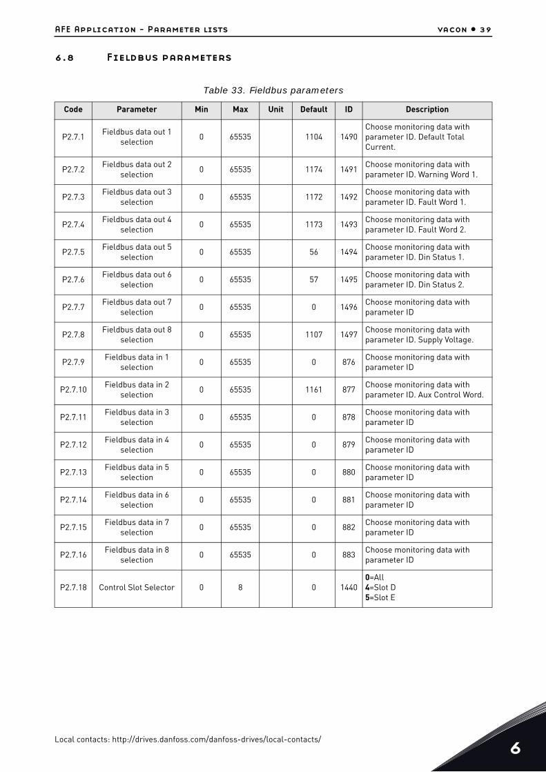
6.8 Fieldbus parameters
Table 33. Fieldbus parameters
Code Parameter Min Max Unit Default ID Description
P2.7.1Fieldbus data out 1
selection0 65535 1104 1490
Choose monitoring data with parameter ID. Default Total Current.
P2.7.2Fieldbus data out 2
selection0 65535 1174 1491
Choose monitoring data with parameter ID. Warning Word 1.
P2.7.3Fieldbus data out 3
selection0 65535 1172 1492
Choose monitoring data with parameter ID. Fault Word 1.
P2.7.4Fieldbus data out 4
selection0 65535 1173 1493
Choose monitoring data with parameter ID. Fault Word 2.
P2.7.5Fieldbus data out 5
selection0 65535 56 1494
Choose monitoring data with parameter ID. Din Status 1.
P2.7.6Fieldbus data out 6
selection0 65535 57 1495
Choose monitoring data with parameter ID. Din Status 2.
P2.7.7Fieldbus data out 7
selection0 65535 0 1496
Choose monitoring data with parameter ID
P2.7.8Fieldbus data out 8
selection0 65535 1107 1497
Choose monitoring data with parameter ID. Supply Voltage.
P2.7.9Fieldbus data in 1
selection0 65535 0 876
Choose monitoring data with parameter ID
P2.7.10Fieldbus data in 2
selection0 65535 1161 877
Choose monitoring data with parameter ID. Aux Control Word.
P2.7.11Fieldbus data in 3
selection0 65535 0 878
Choose monitoring data with parameter ID
P2.7.12Fieldbus data in 4
selection0 65535 0 879
Choose monitoring data with parameter ID
P2.7.13Fieldbus data in 5
selection0 65535 0 880
Choose monitoring data with parameter ID
P2.7.14Fieldbus data in 6
selection0 65535 0 881
Choose monitoring data with parameter ID
P2.7.15Fieldbus data in 7
selection0 65535 0 882
Choose monitoring data with parameter ID
P2.7.16Fieldbus data in 8
selection0 65535 0 883
Choose monitoring data with parameter ID
P2.7.18 Control Slot Selector 0 8 0 14400=All 4=Slot D5=Slot E
Local contacts: http://drives.danfoss.com/danfoss-drives/local-contacts/6
6
vacon • 40 AFE Application - Parameter lists
6.9 Protections
6.9.1 General
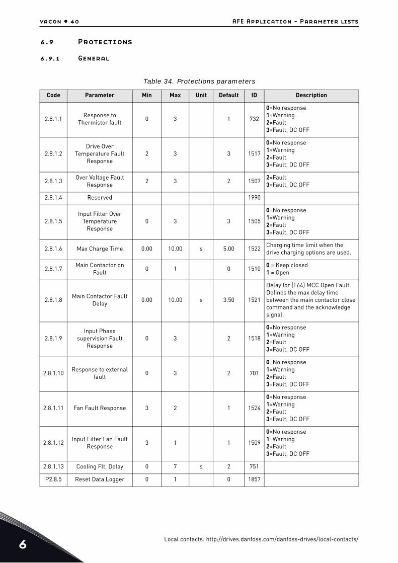
Table 34. Protections parameters
Code Parameter Min Max Unit Default ID Description
2.8.1.1Response to
Thermistor fault0 3 1 732
0=No response1=Warning2=Fault3=Fault, DC OFF
2.8.1.2Drive Over
Temperature Fault Response
2 3 3 1517
0=No response1=Warning2=Fault3=Fault, DC OFF
2.8.1.3Over Voltage Fault
Response 2 3 2 1507
2=Fault3=Fault, DC OFF
2.8.1.4 Reserved 1990
2.8.1.5Input Filter Over
Temperature Response
0 3 3 1505
0=No response1=Warning2=Fault3=Fault, DC OFF
2.8.1.6 Max Charge Time 0.00 10.00 s 5.00 1522Charging time limit when the drive charging options are used.
2.8.1.7Main Contactor on
Fault0 1 0 1510
0 = Keep closed1 = Open
2.8.1.8Main Contactor Fault
Delay0.00 10.00 s 3.50 1521
Delay for (F64) MCC Open Fault. Defines the max delay time between the main contactor close command and the acknowledge signal.
2.8.1.9Input Phase
supervision Fault Response
0 3 2 1518
0=No response1=Warning2=Fault3=Fault, DC OFF
2.8.1.10Response to external
fault0 3 2 701
0=No response1=Warning2=Fault3=Fault, DC OFF
2.8.1.11 Fan Fault Response 3 2 1 1524
0=No response1=Warning2=Fault3=Fault, DC OFF
2.8.1.12Input Filter Fan Fault
Response3 1 1 1509
0=No response1=Warning2=Fault3=Fault, DC OFF
2.8.1.13 Cooling Flt. Delay 0 7 s 2 751
P2.8.5 Reset Data Logger 0 1 0 1857
Local contacts: http://drives.danfoss.com/danfoss-drives/local-contacts/
AFE Application - Parameter lists vacon • 41
6.9.2 PT-100
6.9.3 Earth fault
6.9.4 Fieldbus
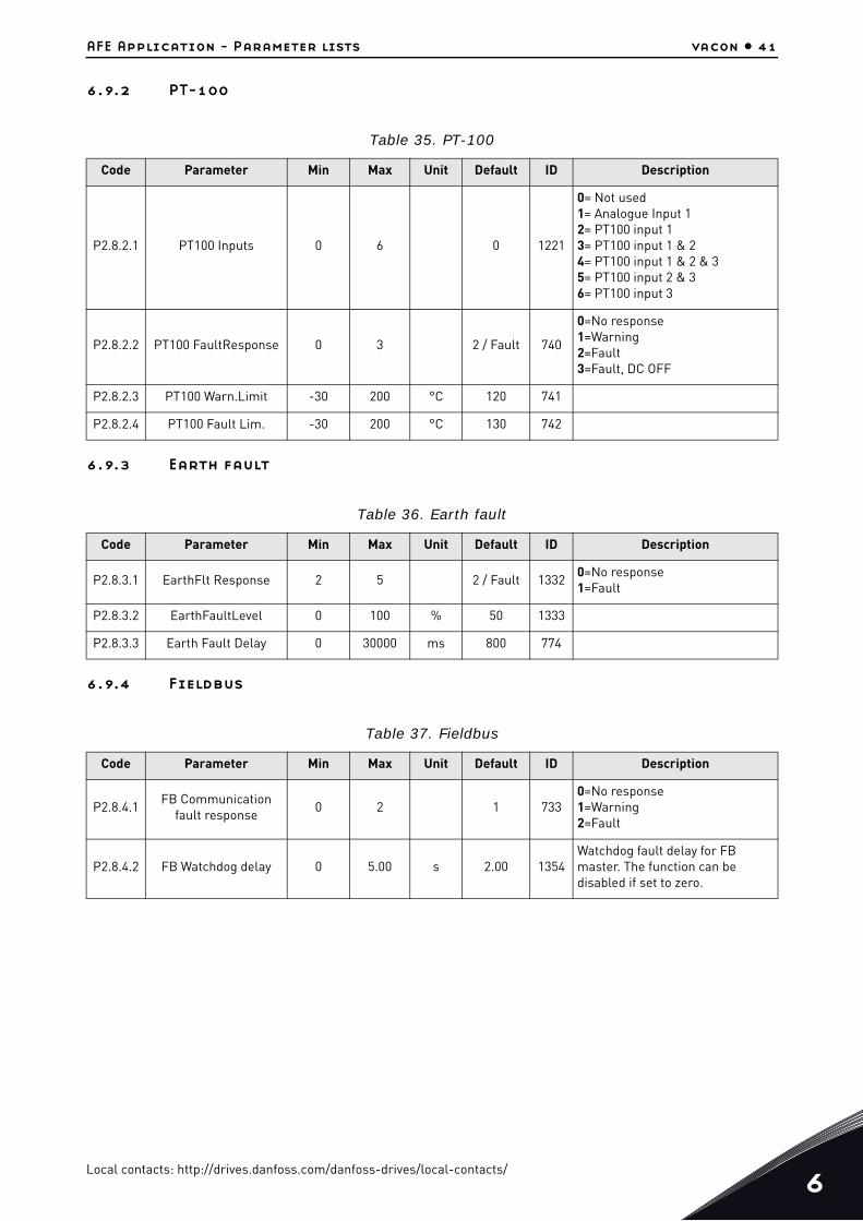
Table 35. PT-100
Code Parameter Min Max Unit Default ID Description
P2.8.2.1 PT100 Inputs 0 6 0 1221
0= Not used 1= Analogue Input 12= PT100 input 13= PT100 input 1 & 24= PT100 input 1 & 2 & 35= PT100 input 2 & 36= PT100 input 3
P2.8.2.2 PT100 FaultResponse 0 3 2 / Fault 740
0=No response1=Warning2=Fault3=Fault, DC OFF
P2.8.2.3 PT100 Warn.Limit -30 200 °C 120 741
P2.8.2.4 PT100 Fault Lim. -30 200 °C 130 742
Table 36. Earth fault
Code Parameter Min Max Unit Default ID Description
P2.8.3.1 EarthFlt Response 2 5 2 / Fault 13320=No response1=Fault
P2.8.3.2 EarthFaultLevel 0 100 % 50 1333
P2.8.3.3 Earth Fault Delay 0 30000 ms 800 774
Table 37. Fieldbus
Code Parameter Min Max Unit Default ID Description
P2.8.4.1FB Communication
fault response0 2 1 733
0=No response1=Warning2=Fault
P2.8.4.2 FB Watchdog delay 0 5.00 s 2.00 1354Watchdog fault delay for FB master. The function can be disabled if set to zero.
Local contacts: http://drives.danfoss.com/danfoss-drives/local-contacts/6

6
vacon • 42 AFE Application - Parameter lists
6.10 Auto reset parameters
6.11 DIN ID Control
6.12 Keypad control
6.13 System menu
For parameters and functions related to the general use of the AC drive, such as application and language selection, customised parameter sets or information about the hardware and software, see the VACON® NXS/P User Manual.
6.14 Expander boards
The M7 menu shows the expander and option boards attached to the control board and board-re-lated information. For more information, see the VACON® NXS/P User Manual and VACON® I/O Op-tion Board User Manual.
Table 38. Auto reset parameters
Code Parameter Min Max Unit Default ID Description
P2.9.1 Wait time 0.10 10.00 s 0.50 717
P2.9.2 Trial time 0.00 60.00 s 30.00 718
P2.9.3Number of tries after
overvoltage trip0 10 0 721
P2.9.4Number of tries after
over current trip0 3 0 722
P2.9.5Number of tries after
external fault trip0 10 0 725
P2.9.6 Fault Simulation 0 65535 0 1569
Table 39. DIN ID Control parameters
Code Parameter Min Max Unit Default Cust ID Description
P2.10.1 ID Control DIN 0.1 E.10 0.1 1570 Slot. Board input No.
P2.10.2 Controlled ID 0 10000 0 1571Select ID that is controlled by digital input
P2.10.3 False value -32000 32000 0 1572 Value when DI is low
P2.10.4 True value -32000 32000 0 1573 Value when DI is high
Table 40. Keypad control parameters
Code Parameter Min Max Unit Default ID Description
P3.1 Control place 2 0 2 14030=Fieldbus1=I/O terminal2=Keypad (Default)
Local contacts: http://drives.danfoss.com/danfoss-drives/local-contacts/

Description of parameters vacon • 43
7. DESCRIPTION OF PARAMETERS
7.1 Basic parameters
P2.1.1 RATED LINE VOLTAGE [# V] ID1201
This parameter sets the incoming line voltage for the regenerative drive. The maximum value is 690V. Set this parameter to the nominal line voltage at the installation site.
P2.1.2 RATED LINE CURRENT [A] ID113
Rated current capacity of the supply or the transformer. May need to be set if AFE is oversized com-pared to LCL or feeding transformer capacity. For testing purposes, the feeding transformer shouldnot be less than 20% of the unit nominal current or following breakers or fuses.
P2.1.3 RATED LINE POWER [KW] ID116
Set here the rated active power of the system.
P2.1.4 PARALLEL AFE ID1501
0 = Single AFE
1 = Parallel AFE
When selecting the parallel AFE DC, Drooping is set to 4.00% and modulation is synchronized to re-duce circulating current if drives are in common DC bus.
Local contacts: http://drives.danfoss.com/danfoss-drives/local-contacts/7
7
vacon • 44 Description of parameters
7.2 Reference Handling
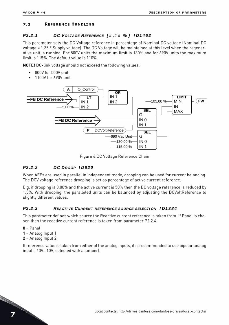
P2.2.1 DC VOLTAGE REFERENCE [#,## %] ID1462
This parameter sets the DC Voltage reference in percentage of Nominal DC voltage (Nominal DCvoltage = 1.35 * Supply voltage). The DC Voltage will be maintained at this level when the regener-ative unit is running. For 500V units the maximum limit is 130% and for 690V units the maximumlimit is 115%. The default value is 110%.
NOTE! DC-link voltage should not exceed the following values:
• 800V for 500V unit• 1100V for 690V unit
Figure 6.DC Voltage Reference Chain
P2.2.2 DC DROOP ID620
When AFEs are used in parallel in independent mode, drooping can be used for current balancing.The DCV voltage reference drooping is set as percentage of active current reference.
E.g. if drooping is 3.00% and the active current is 50% then the DC voltage reference is reduced by1.5%. With drooping, the paralleled units can be balanced by adjusting the DCVoltReference toslightly different values.
P2.2.3 REACTIVE CURRENT REFERENCE SOURCE SELECTION ID1384
This parameter defines which source the Reactive current reference is taken from. If Panel is cho-sen then the reactive current reference is taken from parameter P2.2.4.
0 = Panel1 = Analog Input 12 = Analog Input 2
If reference value is taken from either of the analog inputs, it is recommended to use bipolar analoginput (-10V…10V, selected with a jumper).
FWLIMIT
MININMAX
105,00 %
SELGIN 0IN 1
690 Vac Unit130,00 %115,00 %
ORIN 1IN 2
SELGIN 0IN 1
A IO_Control
LTIN 1IN 25,00 %
P DCVoltReference
FB DC Reference
FB DC Reference
Local contacts: http://drives.danfoss.com/danfoss-drives/local-contacts/

Description of parameters vacon • 45
Figure 7.Analog input scaling (bipolar)
P2.2.4 REACTIVE CURRENT REFERENCE ID1459
This parameter sets the reference for the reactive current in percentage of the rated current. Thiscan be used for power factor correction of AFE system or reactive power compensation.
A positive value makes inductive power to the grid
A negative value makes capacitive power to the grid.
Reactive current reference is taken from this parameter if panel has been chosen to be the sourcefor Reactive current reference (P2.2.3 = 0).
-10V
10V
100,0%
-100,0%
Inputvoltage[V]
Reactive current ref. [%]
11286_uk
Local contacts: http://drives.danfoss.com/danfoss-drives/local-contacts/7
7
vacon • 46 Description of parameters
7.3 Input signals
7.3.1 Digital inputs
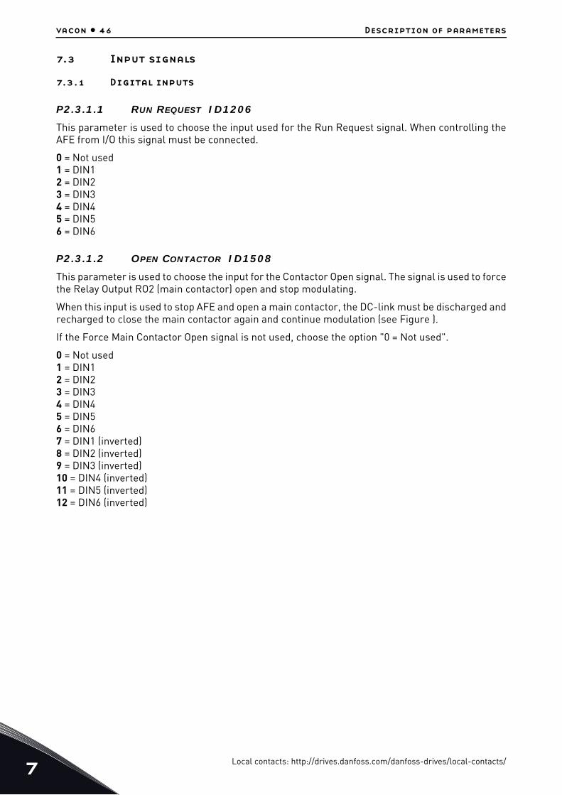
P2.3.1.1 RUN REQUEST ID1206
This parameter is used to choose the input used for the Run Request signal. When controlling theAFE from I/O this signal must be connected.
0 = Not used1 = DIN12 = DIN23 = DIN34 = DIN45 = DIN56 = DIN6
P2.3.1.2 OPEN CONTACTOR ID1508
This parameter is used to choose the input for the Contactor Open signal. The signal is used to forcethe Relay Output RO2 (main contactor) open and stop modulating.
When this input is used to stop AFE and open a main contactor, the DC-link must be discharged andrecharged to close the main contactor again and continue modulation (see Figure ).
If the Force Main Contactor Open signal is not used, choose the option "0 = Not used".
0 = Not used1 = DIN12 = DIN23 = DIN34 = DIN45 = DIN56 = DIN67 = DIN1 (inverted)8 = DIN2 (inverted)9 = DIN3 (inverted)10 = DIN4 (inverted)11 = DIN5 (inverted)12 = DIN6 (inverted)
Local contacts: http://drives.danfoss.com/danfoss-drives/local-contacts/

Description of parameters vacon • 47
Figure 8.Contactor Open
P2.3.1.3 LCL TEMPERATURE MONITOR X52 ID1179 "LCL TEMP. X52"
This parameter defines if the drive monitors the status of the LCL over temperature switch signal.This wire is marked as "X52" when not using integrated DC/DC power supply.
This signal is normally used in cabinet installations. If the LCL Over temperature monitoring signalis not used in the system, choose the option "0 = Not used".
See parameter P2.3.1.2 for the list of values.
P2.3.1.4 MAIN CONTACTOR ACKNOWLEDGE ID1453
This parameter defines what input is used to monitor the status of the main contactor of the unit. Ifthe feedback does not correspond the control signal within set time delay, the drive will indicateMCC Fault and will not be able to start until proper feedback is given.
See parameter P2.3.1.1 for the list of values.
NOTE! AFE needs feedback signal for correct operation. If feedback is not used there will be 3 sec-ond delay after closing command before drive can be started.
P2.3.1.5 LCL FAN MONITORING (X51) ID1178
This parameter defines if the drive monitors the status of the LCL Fan of the unit. When the moni-toring function is used, the unit will give a warning if the LCL fan stops working and the LCL tem-perature reaches warning level.
Check from hardware if LCL is using X51 for fan monitoring or for LCL Temperature monitoring. Ifhardware uses X51 for fan monitoring, use this parameter. If it is used for LCL temperature moni-toring, use P2.3.1.10 LCL Temperature Monitoring X51.
This signal is normally used in cabinet installations. If the status of the LCL fan is not monitored inthe system, choose the option "0 = Not used".
See parameter P2.3.1.2 for the list of values.
P2.3.1.6 FAULT RESET ID1208
0.8 * DCnominal
Contactor Open Contactor Close(RO2) = 1)
Charging isstarted
DC-link voltage
11287_uk
Local contacts: http://drives.danfoss.com/danfoss-drives/local-contacts/7

7
vacon • 48 Description of parameters
This parameter defines which digital input is used to reset faults.
See parameter P2.3.1.1 for the list of values.
P2.3.1.7 EXTERNAL FAULT ID1214
This parameter defines if the drive monitors the status of the External fault input. The response tothe fault can be selected with the parameter P2.7.2.
See parameter P2.3.1.2 for the list of values.
P2.3.1.8 RUN ENABLE ID1212
This parameter defines which digital input is used for the external Run Enable signal. If Run Enableis used, the drive does not go to Ready state until the Run Enable goes high.
See parameter P2.3.1.1 for the list of values.
P2.3.1.9 COOLING MONITOR ID750
OK input from the cooling unit.
P2.3.1.10 LCL TEMPERATURE MONITOR X51 ID750 "LCL TEMP. X51"
This parameter defines if the drive monitors the status of the LCL over temperature switch signalfrom X51. This wire is marked as "X51" when not using integrated DC/DC power supply.
Check from hardware if LCL is using X51 for fan monitoring or for LCL Temperature monitoring. Ifhardware uses X51 for temperature monitoring, use this parameter. If it is used for LCL fan moni-toring, use P2.3.1.5 LCL Fan Monitoring (X51).
This signal is normally used in cabinet installations. If LCL Over temperature monitoring signal isnot used in the system, choose the option "0 = Not used".
See parameter P2.3.1.2 for the list of values.
Local contacts: http://drives.danfoss.com/danfoss-drives/local-contacts/

Description of parameters vacon • 49
7.3.2 Analogue Inputs
P2.3.2.1 ANALOG INPUT 1 MINIMUM ID1227
Minimum voltage or Current level at AI1.
0=0V / 0mA,
1=2V / 4mA
P2.3.2.2 ANALOG INPUT 1 FILTER TIME ID1228
Filter time in seconds for the filtering of signal connected to AI1. The range of time can be selectedfrom 0.01 sec to 10.00 sec.
P2.3.2.3 ANALOG INPUT 2 MINIMUM ID1231
This parameter defines the minimum voltage or current on the AI2 terminal on OPT-A1 board.
0=0V / 0mA,
1=2V / 4mA
P2.3.2.4 ANALOGUE INPUT 2 FILTER TIME ID1232
Filter time in seconds for the filtering of signal connected to AI2. The range of time can be selectedfrom 0.01 sec to 10.00 sec.
Local contacts: http://drives.danfoss.com/danfoss-drives/local-contacts/7

7
vacon • 50 Description of parameters
7.4 Output signals
7.4.1 Digital outputs
P2.4.1.1 DO1 ID1216
This parameter defines which signal is connected to digital output 1.
0 = Digital output can be set from Fieldbus (Auxiliary Control Word, bit 13).
1 = Ready
2 = Running
3 = Fault
4 = No Fault
5 = Warning
6 = At Reference
7 = Regen Active (Unit is regenerating power)
8 = Charge DC
This output function is used to charge DC. This function can be used only when the Run Enable func-tion is also in use. When run enable is HIGH and there are no active faults, the rising edge on thestart command will start the DC charging and if charging is successful, the drive will go to RunState.
9 = Ready / Warning (blink).
10 = Over temperature fault (Drive over temperature or Fan not working)
11 = DC voltage above limit set with parameter P2.5.6.1
P2.4.1.2 DO2 ID1217
Select the signal for controlling the RO1 of OPT-A2 option board.
See parameter P2.3.1.1 for the list of values.
P2.4.1.3 DO3, SLOT B: OUTPUT 2 (RO2) ID1218
This output control Main Contactor. Function cannot be changed.
P2.4.1.4-P2.4.1.13 DO4- DO12 ID1385 - ID1429
These parameters are only visible when there are option cards with digital outputs installed in theAFE. If, for example, the option card OPT-B5 has been installed, the parameters for outputs DO3-DO5 become visible.
See parameter P2.3.1.1 for the list of values.
7.4.2 Analogue outputs
NOTE! This menu is visible in the panel, if Analogue Input 1 is not used for PT100 measurement(P2.2.2.2 = 0).
Local contacts: http://drives.danfoss.com/danfoss-drives/local-contacts/
Description of parameters vacon • 51
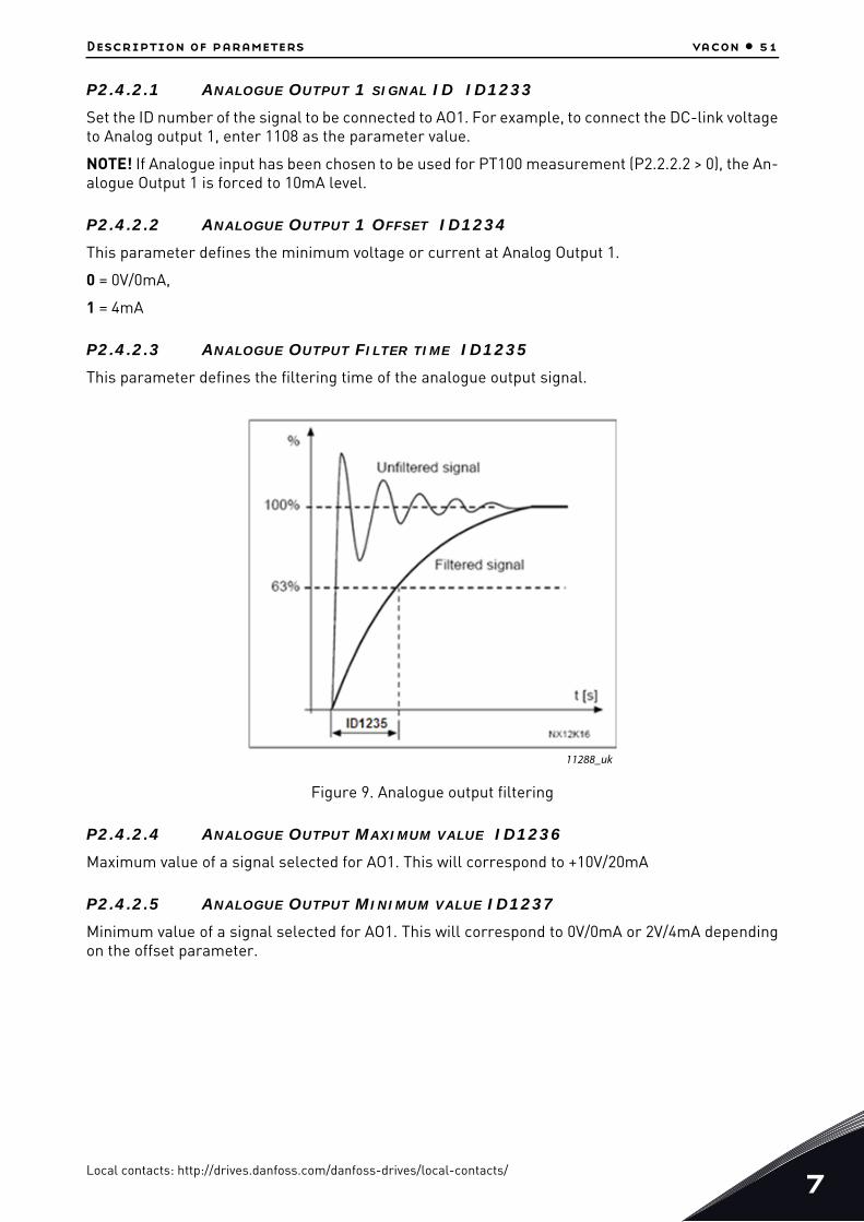
P2.4.2.1 ANALOGUE OUTPUT 1 SIGNAL ID ID1233
Set the ID number of the signal to be connected to AO1. For example, to connect the DC-link voltageto Analog output 1, enter 1108 as the parameter value.
NOTE! If Analogue input has been chosen to be used for PT100 measurement (P2.2.2.2 > 0), the An-alogue Output 1 is forced to 10mA level.
P2.4.2.2 ANALOGUE OUTPUT 1 OFFSET ID1234
This parameter defines the minimum voltage or current at Analog Output 1.
0 = 0V/0mA,
1 = 4mA
P2.4.2.3 ANALOGUE OUTPUT FILTER TIME ID1235
This parameter defines the filtering time of the analogue output signal.
Figure 9. Analogue output filtering
P2.4.2.4 ANALOGUE OUTPUT MAXIMUM VALUE ID1236
Maximum value of a signal selected for AO1. This will correspond to +10V/20mA
P2.4.2.5 ANALOGUE OUTPUT MINIMUM VALUE ID1237
Minimum value of a signal selected for AO1. This will correspond to 0V/0mA or 2V/4mA dependingon the offset parameter.
11288_uk
Local contacts: http://drives.danfoss.com/danfoss-drives/local-contacts/7

7
vacon • 52 Description of parameters
7.5 Limit settings
7.5.1 Current Limits
P2.5.1.1 CURRENT LIMIT [A] ID107
Sets the current limit for the regenerative supply unit. Set this to correspond to the maximum re-quired load or peak overload of the unit, bearing in mind that the load might consist of several motordrive units.
Maximum value 2 * IH depends on the unit size.
7.5.2 Power Limits
P2.5.2.1 POWER LIMIT MOTORING SIDE ID1289
This parameter sets the power limit for the motor side operation of the regenerative unit. 100.0% isequal to nominal power. Motoring Side operation means that the power flows from AC side to DCside.
P2.5.2.2 POWER LIMIT GENERATOR SIDE ID1290
This parameter sets the power limit for the generator side operation of the regenerative unit.100.0% is equal to nominal power. The Generator Side operation means that the power flows fromDC side to AC side. Setting a too low value may lead to overvoltage fault. In some cases, the powercan not be fed to the ship grid and AFE is used for purely low harmonic requirements. In these cas-es, the BCU may be needed to consume the excess energy.
7.5.3 Auto Start Stop function
P2.5.3.1 START FUNCTION
The parameter determines how the unit behaves when starting and stopping.
0 = Normal. Regenerative unit starts only with the run request.
1 = Auto. Regenerative unit will start automatically when the energy is to be fed back to the mainnetwork (regeneration) and stops when there is no regeneration.
P2.5.3.2 AUTO STOP LEVEL
Active current level when regeneration is stopped in Auto mode. When the active current value ishigher than this value, regeneration will be stopped.
P2.5.3.3 MINIMUM RUN TIME ID1281 "MINIMUM RUN TIME"
This parameter defines the minimum running time when AFE starting is triggered by rising DC volt-age. This parameter is applicable only when operating in Auto mode (P2.5.3.1 = 1).
P2.5.3.4 STOP DELAY ID1282 "STOP DELAY"
This parameter defines time period when internal DC reference is ramped to minimum before stop-ping the AFE, if no regenerative power is detected during this time. This parameter is applicableonly when operating in Auto mode (P2.5.3.1 = 1).
Local contacts: http://drives.danfoss.com/danfoss-drives/local-contacts/

Description of parameters vacon • 53
7.5.4 DC Voltage limit parameters
P2.5.4.1 DC VOLTAGE SUPERVISION LIMIT ID1454
This parameter sets a supervision limit for the DC link voltage. If the voltage increases above this,this signal goes HIGH. This signal can be connected to digital output and it is copied to Main StatusWord, Bit 10. This value does not limit the DC-link voltage but it can be used for monitoring purpos-es.
Local contacts: http://drives.danfoss.com/danfoss-drives/local-contacts/7

7
vacon • 54 Description of parameters
7.6 Drive control
P2.6.1 SWITCHING FREQUENCY ID601
The switching frequency of the IGBT bridge in kHz. Changing the default value may impact on theLCL filter operation.
P2.6.2 REGEN OPTIONS 1 ID1463
P2.6.3 REGEN OPTIONS 2 ID1464
This packed bit word is made for enabling/disabling different control options for regeneration con-trol:
B0 = Disable DCV reduction with reactive reference generation with high line voltage.
B1 = Disable LCL reactive power compensation.
B5 = Disable all harmonic elimination compensation
This is active by default. When activated, this function will reduce a little the 5th and 7th harmonics.This will not reduce harmonics of the grid, only drive’s own harmonics.
B8 = Enable double pulse synchronization
This option will generate two synchronization pulses instead of one. This may help synchronizationon a weak grid.
B9 = Enable soft synchronization (>= FI9)
This function enables zero crossing detection on FI9 and bigger units. When it is active and there isa connection to grid while drive is in stop state, the Supply Frequency is updated by detected fre-quency.
B12 = Enable floating DC reference. DC-link voltage will follow line voltage.
While run state drive can detect the Supply Voltage, if supply voltage changes, also the internal DCReference is changed so that the DC Voltage is:
DC Voltage= Measured Supply Voltage*1.35*DC Reference
B13 = Enable use of D7 board for start synchronization.
When OPT-D7 board is installed this bit will activate synchronization by using voltage angle and fre-quency information from D7 board. Note that the phase order needs to be the same both in OPT-D7and input phases. It is also recommended to keep frequency on positive side. Note that the frequen-cy of the D7 board can be the same as the Supply Frequency but the phase order can still be wrong.
P2.6.4 START UP DELAY ID1500
This parameter defines a starting delay when the run command is given. When programming dif-ferent delays to the paralleled units, the units will start in sequence. This is needed in parallel unitsso that synchronization does not happen simultaneously with all drives. Simultaneous starting maylead to failed synchronization. The recommended value between the drives is 500 ms.
Local contacts: http://drives.danfoss.com/danfoss-drives/local-contacts/

Description of parameters vacon • 55
Figure 10.Start up delay
P2.6.5 MODULATOR TYPE ID1516
This parameter is for changing the modulator type. With the ASIC (HW) modulator the current dis-tortion is lower, but losses are higher compared to a software modulator. It is recommended to usea software modulator.
0 = Hardware modulator: ASIC modulator with classic third harmonic injection. Spectrum is slight-ly better compared to Software 1 modulator.
1 = Software modulator 1: Symmetric vector modulator with symmetrical zero vectors. Currentdistortion is less than with software modulator 2 if boosting is used.
2 = Software modulator 2: Symmetric BusClamb in which one switch always conducts 60 degreeseither to negative or positive DC-rail. Switching losses are reduced without different heating of up-per and lower switches. Spectrum is narrow. Not recommended for parallel units.
3 = Software modulator 3: Unsymmetric BusClamb in which one switch always conducts 120 de-grees to negative DC-rail to reduce switching losses. Drawback is that upper and lower switchesare unevenly loaded and spectrum is wide. Not recommended for parallel units.
4 = Software modulator 4: Pure sine wave, sinusoidal modulator without harmonic injection. Ded-icated to be used in back-to-back test benches etc. to avoid circulating third harmonic current.Drawback is that required DC voltage is 15% higher compared to other modulator types.
P2.6.6 CONTROL OPTIONS ID1798
B05 = +32 = Use ENC C1 as fast RunEnable.
B06 = +64 = Enable Fan Fault while no DC Voltage.
B12 = +4096 = Disable Dead Time Hw Compensation.
B13 = +8192 = Enable MCB Fault autoreset.
B14 = +16384 = Enable MCB Fault when feedback is lost in Run state.
Time * 500 ms
StopAFE 1
Run
StopAFE 2
Run
StopAFE 3
Run
StopAFE 4
Run
11289_uk
Local contacts: http://drives.danfoss.com/danfoss-drives/local-contacts/7

7
vacon • 56 Description of parameters
P2.6.6 OPERATION TIME ID1855
Stored Operation Time. When application is reloaded, the operation hours will go to zero if this pa-rameter is not updated.
Monitoring signal is in hours with two decimals.
Parameter is in the following format:
xx (Years) XX (Months) XX (Days) XX (Hours) XX Minutes
1211292359 -> 12 years, 11 months, 29 days, 23 hours and 59 minutes.
7.6.1 Drive control
P2.6.8.1 VOLTAGE CONTROLLER KP ID1451
This parameter sets the gain for the DC link PI voltage controller.
P2.6.8.2 VOLTAGE CONTROLLER TI ID1452
This parameter sets the time constant in ms of the DC link PI controller.
P2.6.8.3 ACTIVE CURRENT CONTROLLER KP ID1455
This parameter sets the gain of the controller for the active current of the regenerative unit.
P2.6.8.4 ACTIVE CURRENT CONTROLLER TI ID1456
This parameter sets the time constant of the controller for the active current of the regenerativeunit (15 equals 1.5ms).
P2.6.8.5 SYNC KP ID1457
This parameter sets the gain of the synchronisation controller used to synchronise the switching tothe supply.
P2.6.8.6 SYNC TI ID1458
This parameter sets the time constant of the controller used to synchronise the switching to thesupply (15 equals 7ms).
P2.6.8.7 MODULATOR INDEX LIMIT ID655
This parameter can be used to control how the drive modulates the output voltage. The lower valuemay improve the current waveform, but causes the DC voltage to increase when the line voltage ishigh.
P2.6.8.8 MAIN CONTACTOR START DELAY ID1519
Main contactor On delay. The delay from the Main contactor acknowledge signal to the modulationstart. If the main contactor feedback function is bypassed, this time is internally set to 2 seconds.
P2.6.8.9 CAPACITOR SIZE ID1460
This parameter defines the reactive current going to the LCL filter capacitor. It compensates theLCL effect to the reactive current by adjusting the reactive current reference internally. The induc-tor size is also added to compensation. If set correctly, the power factor on the grid side will be 1.
Local contacts: http://drives.danfoss.com/danfoss-drives/local-contacts/

Description of parameters vacon • 57
P2.6.8.10 INDUCTOR SIZE ID1461
This parameter defines voltage losses in percentage of the nominal voltage at 100% active current.This value is internally added to the reactive current reference thus giving power factor 1 on the gridside, if set correctly together with Capacitor Size. The transformer and feeding cables can be com-pensated by increasing this value.
P2.6.8.11 DYNAMICSUPPORTKP ID1797
Local contacts: http://drives.danfoss.com/danfoss-drives/local-contacts/7
7
vacon • 58 Description of parameters
7.7 Fieldbus parameters
P2.7.1 -P2.7.8 FIELDBUS DATA OUT 1-8 SELECTION ID1490-ID1497
Using these parameters, you can monitor any monitoring or parameter value from the fieldbus. En-ter the ID number of the item you wish to monitor for the value of these parameters.
P2.7.9 -P2.7.16 FIELDBUS DATA IN 1-8 SELECTION ID876-ID883
Using these parameters, you can control any parameter from the fieldbus. Enter the ID number ofthe item you wish to control for the value of these parameters.
P2.7.17 CONTROL SLOT SELECTOR ID1440 "CONTROLSLOTSEL."
This parameter defines which slot is used as the main control place when two fieldbus boards havebeen installed in the drive. When values 6 or 7 are selected, the drive uses the Fast Profibus profile.When the Fast Profibus profile is used, the type 'B' boards or other C type boards cannot be used.
NOTE: Set first the Slave Address and the PPO type before selecting the Fast Profibus mode.
0 = All slots
4 = Slot D
5 = Slot E
6 = Slot D, Fast Profibus support
7 = Slot E, Fast Profibus support
Local contacts: http://drives.danfoss.com/danfoss-drives/local-contacts/

Description of parameters vacon • 59
7.8 Protections
P2.8.1.1 RESPONSE TO THERMISTOR FAULT ID732
0 = No response1 = Warning2 = Fault (the drive will stop modulation leaving main contactor closed)3 = Fault, DC off (main contactor open)
Setting the parameter to 0 will deactivate the protection.
P2.8.1.2 RESPONSE TO DRIVE OVERTEMPERATURE FAULT ID1517
2 = Fault3 = Fault, DC off (main contactor open)
For the warning and tripping limits, see the User manual of the AC drive. Note that air cooled andliquid cooled limits are different.
P2.8.1.3 RESPONSE TO OVERVOLTAGE FAULT ID1507
2 = Fault3 = Fault, DC off (main contactor open)
P2.8.1.4 RESERVED ID1990
P2.8.1.5 RESPONSE TO INPUT FILTER OVER TEMPERATURE ID1505
This parameter defines a response to the LCL over temperature fault. The LCL fault is monitoredthrough the digital input defined in group G2.3.1.
0 = No response1 = Warning2 = Fault (the drive will stop modulation leaving the main contactor closed)3 = Fault, DC off (main contactor open)
P2.8.1.6 MAX CHARGE TIME ID1522
When the drive charging options is used, this parameter defines the maximum time limit for charg-ing.
P2.8.1.7 MAIN CONTACTOR ON FAULT ID1510
This parameter defines a response to ANY fault that occurs in the AFE.
0 = Main Contactor is kept closed in case of fault
- Faults that have been defined to open the Main Contactor are still active.
1 = Any fault in the drive will open the Main Contactor.
NOTE! F1 over current, F31 IGBT HW and F41 IGBT SW will always open Main Circuit Breaker (MCB).
Local contacts: http://drives.danfoss.com/danfoss-drives/local-contacts/7

7
vacon • 60 Description of parameters
P2.8.1.8 MAIN CONTACTOR OPEN FAULT DELAY ID1521
Delay for Main contactor open fault. The delay between the main contactor control relay close com-mand and the main contactor acknowledge signal. If the acknowledge signal is not received withinthis time, a fault F64 will be trigged.
P2.8.1.9 RESPONSE TO INPUT PHASE SUPERVISION ID1518
0 = No response1 = Warning2 = Fault3 = Fault, DC off (main contactor open)
The input phase supervision ensures that the input phases of the AC drive has an approximatelyequal current.
P2.8.1.10 RESPONSE TO EXTERNAL FAULT ID701
This parameter defines a response to external fault. If the drive monitors the state of the externalfault input (value of P2.2.1.7 > 0) and a fault occurs the drive can be set to respond to the fault.
0 = No response1 = Warning2 = Fault (the drive will stop modulation leaving main contactor closed)3 = Fault, DC off (main contactor open)
P2.8.1.11 FAN FAULT RESPONSE ID1524
This parameter defines a response for the Fan fault.
Drive Fan and LCL inverter controlled fan
1 = Warning2 = Fault3 = Fault, DC off (main contactor open)
P2.8.1.12 INPUT FILTER FAN FAULT RESPONSE ID1509
This parameter defines a response to the Input Filter Fan fault. If the drive monitors the state of theinput filter fan (value of P2.2.1.5 > 0) and a fault occurs the drive can be set to respond to the fault.
0 = No response1 = Warning2 = Fault (the drive will stop modulation leaving main contactor closed)
P2.8.1.13 COOLINGFLT.DELAY
Protection for liquid cooled units. An external sensor is connected to the drive (DI: Cooling Monitor)to indicate if cooling liquid is circulating. If the drive is in Stop state this is only a warning. In Runstate, the drive will issue a fault with a coast stop.
This parameter defines the delay after which the drive goes to fault state when 'Cooling OK' signalis missing.
7.8.1 PT100 Temperature
P2.8.2.1 PT100 INPUT SELECTION ID1221
Selects the analogue input to be used for the temperature measurement using a PT100 sensor.
Local contacts: http://drives.danfoss.com/danfoss-drives/local-contacts/

Description of parameters vacon • 61
If the Analogue input has been used for the PT100 measurement, the Analogue Output 1 is forcedto 10mA level and it is used as a power supply for the PT100 sensor. The connection has been illus-trated in Figure .
0 = Not used1 = AI12-6 = Measurements are taken from PT-100 board
Figure 11. PT100 connection, with Analogue input configuration
P2.8.2.2 RESPONSE TO PT100 FAULT ID740
0 = No response1 = Warning2 = Fault3 = Fault, DC off (main contactor open)
Setting the parameter to 0 will deactivate the protection.
P2.8.2.3 PT100 WARNING LIMIT ID741
Set here the limit at which the PT100 warning will be activated.
P2.8.2.4 PT100 FAULT LIMIT ID742
Set here the limit at which the PT100 fault will be activated.
7.8.2 Earth fault
The earth fault protection ensures that the sum of the output phase currents is zero. The overcur-rent protection is always working and protects the AC drive from earth faults with high currents.
P2.8.3.1 RESPONSE TO EARTH FAULT ID1332
The earth fault protection ensures that the sum of the phase currents is zero. The overcurrent pro-tection is always working and protects the AC drive from earth faults with high currents.
0 = No response1 = Fault
P2.8.3.2 EARTH FAULT CURRENT ID1333
Max. level of Earth current in percentage of unit current.
P2.8.3.3 EARTH FAULT DELAY ID774 "EARTH FAULTDELAY"
Delay before Earth fault is generated.
AO1+
AO1-
AI+
AI-
PT100
11290_00
Local contacts: http://drives.danfoss.com/danfoss-drives/local-contacts/7

7
vacon • 62 Description of parameters
7.8.3 Fieldbus
P2.8.4.1 RESPONSE TO FIELDBUS FAULT ID733 "FBCOMM.FAULTRESP"
Set here the response for a fieldbus fault if the active control place is fieldbus. For more informa-tion, see the respective Fieldbus Board Manual.
0 = No response1 = Warning2 = Fault
P2.8.4.1 FIELDBUS WATCH DOG DELAY ID1354
Defines the delay after which a fault is generated when the watch dog pulse is missing from field-bus. Set the time to zero to disable watchdog monitoring.
P2.8.5 DATA LOGGER RESET ID1857
Parameter to reset the data logger to its defaults. We recommend you to reset settings after theinitial commissioning if you changed them.
Local contacts: http://drives.danfoss.com/danfoss-drives/local-contacts/

Description of parameters vacon • 63
7.9 Auto restart
P2.9.1 WAIT TIME ID717
Defines the time for the attempted fault reset after the fault trigger has passed. The wait time countstarts only when the cause of the fault has been removed. E.g. external fault digital input is not infault state.
P2.9.2 TRIAL TIME ID718
If the fault trigger appears more often than defined by parameters P2.9.3 to P2.9.5 inside the trialtime, a permanent fault is generated.
P2.9.3 NUMBER OF TRIES AFTER OVERVOLTAGE TRIP ID721
This parameter determines how many automatic restarts can be made during the trial time set byparameter P2.9.2 after an overvoltage trip.
0 = No automatic restart after overvoltage fault trip.>0 = Number of automatic restarts after overvoltage fault trip. The fault is reset and the drive isstarted automatically after the DC-link voltage has returned to the normal level.
P2.9.4 NUMBER OF TRIES AFTER OVERCURRENT TRIP ID722
NOTE! IGBT temp fault also included.
This parameter determines how many automatic restarts can be made during the trial time set bythe parameter P2.9.2.
0 = No automatic restart after overcurrent fault trip>0 = Number of automatic restarts after overcurrent trip and IGBT temperature faults.
P2.9.5 NUMBER OF TRIES AFTER EXTERNAL FAULT TRIP ID725
This parameter determines how many automatic restarts can be made during the trial time set bythe parameter P2.9.2.
0 = No automatic restart after External fault trip>0 = Number of automatic restarts after External fault trip
P2.9.6 FAULT SIMULATION ID1569 "FAULT SIMULATION"
With this parameter it is possible to simulate different faults without actually causing e.g. overcur-rent fault situation.
B00 = +1 = Simulates overcurrent fault (F1)B01 = +2 = Simulates overvoltage fault (F2)B02 = +4 = Simulates undervoltage fault (F9)B03 = +8 = Simulates output phase supervision fault (F11)B04 = +16 = Simulates earth fault (F3)B05 = +32 = Simulates system fault (F8)B06 = +64 = ReservedB07 = +128 = Simulates over temperature warning (W14)B08 = +256 = Simulates over temperature fault (F14)
Local contacts: http://drives.danfoss.com/danfoss-drives/local-contacts/7

7
vacon • 64 Description of parameters
7.10 DIN ID Control
This function is used to control any parameter between two different values with a digital input. Dif-ferent values are given for DI 'low' and DI 'high'.
Figure 12. DIN ID control
P2.10.1 ID CONTROL DIGITAL INPUT ID1570 "ID CONTROL DIN"
Select the digital input to be used for controlling the parameter selected by P2.10.2.
P2.10.2 DIN CONTROLLED ID ID1571 "CONTROLLED ID"
Select the parameter ID controlled by P2.10.1.
P2.10.3 VALUE FOR LOW DIGITAL INPUT (FALSE) ID1572 "FALSE VALUE"
Set here the controlled parameter value when the digital input (P2.10.1) is LOW for the parameterselected by P2.10.2. The function does not recognize decimals. Give, therefore, e.g. 10.00 Hz as'1000'.
P2.10.4 VALUE FOR HIGH DIGITAL INPUT (TRUE) ID1573 "TRUE VALUE"
Set here the controlled parameter value when the digital input (P2.10.1) is HIGH for the parameterselected by P2.10.2. The function does not recognize decimals. Give, therefore, e.g. 10.00 Hz as'1000'.
7.11 Keypad control
P3.1 CONTROL PLACE ID1403
The active control place can be changed with this parameter.
NOTE! Keypad is the default control place.
0 = Fieldbus1 = I/O terminal2 = Keypad (Default)
SELG
IN 0
IN 1
DI ID Control Digital Input
P Value for LOW
P Value for High
P DIN Controlled ID
11291_uk
Local contacts: http://drives.danfoss.com/danfoss-drives/local-contacts/
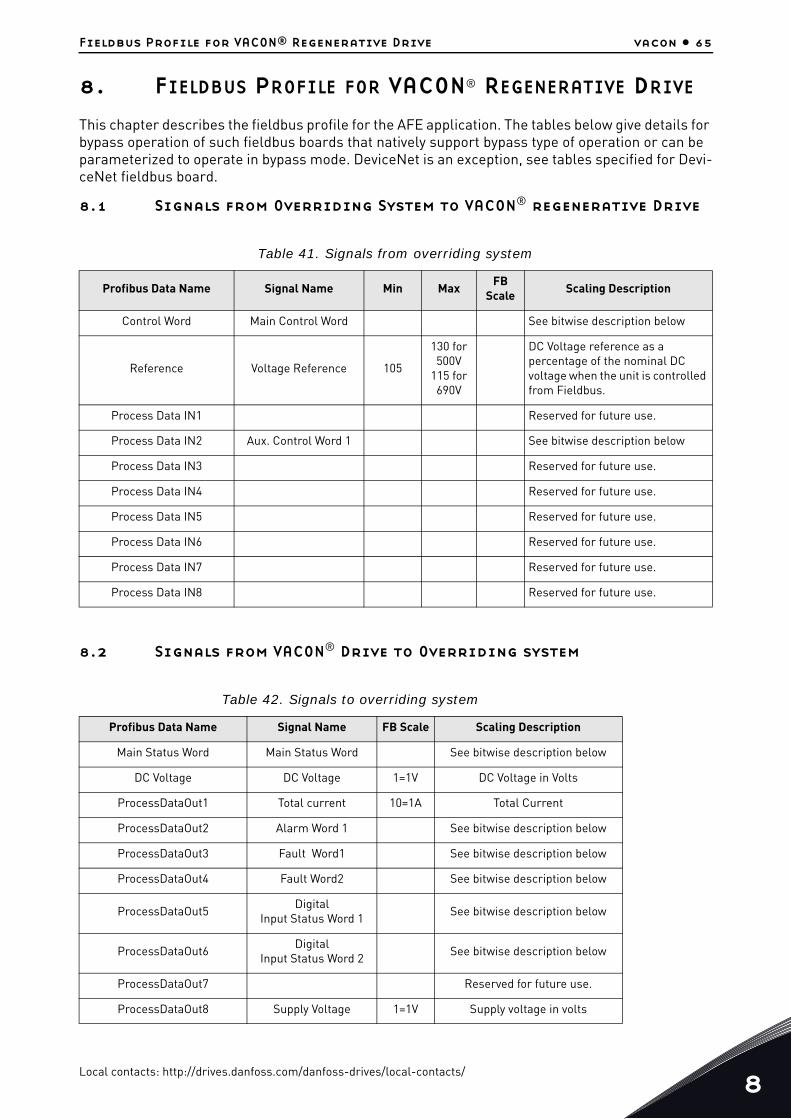
Fieldbus Profile for VACON® Regenerative Drive vacon • 65
8. FIELDBUS PROFILE FOR VACON® REGENERATIVE DRIVE
This chapter describes the fieldbus profile for the AFE application. The tables below give details for bypass operation of such fieldbus boards that natively support bypass type of operation or can be parameterized to operate in bypass mode. DeviceNet is an exception, see tables specified for Devi-ceNet fieldbus board.
8.1 Signals from Overriding System to VACON® regenerative Drive
8.2 Signals from VACON® Drive to Overriding system
Table 41. Signals from overriding system
Profibus Data Name Signal Name Min MaxFB
ScaleScaling Description
Control Word Main Control Word See bitwise description below
Reference Voltage Reference 105
130 for 500V
115 for 690V
DC Voltage reference as a percentage of the nominal DC voltage when the unit is controlled from Fieldbus.
Process Data IN1 Reserved for future use.
Process Data IN2 Aux. Control Word 1 See bitwise description below
Process Data IN3 Reserved for future use.
Process Data IN4 Reserved for future use.
Process Data IN5 Reserved for future use.
Process Data IN6 Reserved for future use.
Process Data IN7 Reserved for future use.
Process Data IN8 Reserved for future use.
Table 42. Signals to overriding system
Profibus Data Name Signal Name FB Scale Scaling Description
Main Status Word Main Status Word See bitwise description below
DC Voltage DC Voltage 1=1V DC Voltage in Volts
ProcessDataOut1 Total current 10=1A Total Current
ProcessDataOut2 Alarm Word 1 See bitwise description below
ProcessDataOut3 Fault Word1 See bitwise description below
ProcessDataOut4 Fault Word2 See bitwise description below
ProcessDataOut5Digital
Input Status Word 1See bitwise description below
ProcessDataOut6Digital
Input Status Word 2See bitwise description below
ProcessDataOut7 Reserved for future use.
ProcessDataOut8 Supply Voltage 1=1V Supply voltage in volts
Local contacts: http://drives.danfoss.com/danfoss-drives/local-contacts/8

8
vacon • 66 Fieldbus Profile for VACON® Regenerative Drive
8.3 Main Control Word
B00: FALSE = No Action, TRUE = PreCharge DC
ON: Drive will start precharge if the function is activated by digital output and the control place is fieldbus.
When control place is not fieldbus, precharging is started from the normal start command.
For fieldbus B10 also needs to be active.
B01: FALSE = Coast stop (OFF 2), TRUE = ON 2
Coast Stop: Drive will make coasting stop.
ON 2: No Coast Stop command
Table 43. Main Control Word ID1160
FALSE TRUE
B00 DC charge Contactor close
0= No Action1= Close DC charge contactor (can be used to control external charge circuit by connecting this signal to digital output, see group G2.4.1).
B01 OFF2 =Stop 0=stop Active. Regenerative control is stopped.1=stop not active
B02 Reserved for future use.
B03 Run 0= Regeneration control not active1= Regeneration control active
B04 Reserved for future use.
B05 Reserved for future use.
B06 Reserved for future use.
B07 Reset 0>1 Reset fault.
B08 Set DC Voltage Ref 1 DC Voltage Reference 1 = 115% of Nominal DCVolt-age.
B09 Set DC Voltage Ref 2 DC Voltage Reference 2 = 120% of Nominal DCVolt-age.
B10 Fieldbus Control 0= No control from fieldbus1=Control from fieldbus
B11 Watchdog
0>1>0>1…1 sec square wave clock. This is used to check data communication between fieldbus master and the drive. Used to generate FB Comm. Fault. This monitoring can be switched off by setting P2.8.4.2 FB Watchdog Delay=0. The drive’s internal communication monitoring is still active at this time.
B12 Reserved for future use.
B13 Reserved for future use.
B14 Reserved for future use.
B15 Reserved for future use.
Local contacts: http://drives.danfoss.com/danfoss-drives/local-contacts/

Fieldbus Profile for VACON® Regenerative Drive vacon • 67
B03: FALSE = Stop Request, TRUE = Start Request
Stop Request: Drive will stop.
Start Request: Start Command to the drive.
B07: FALSE = No significance, TRUE = Fault Acknowledge
Fault Acknowledge: The group signal is acknowledged with a positive edge.
8.4 FB Reference Control
When the DC reference from fieldbus is below 5 (FW: FBSpeedReference < 5), the reference from fieldbus is ignored. When the reference is below 105 (FW: FBSpeedReference < 105), the reference is limited to 105.00%. The FB Reference cannot be activated when the control place is IO Control. MainControlWord B8 and B9 reference function is activated by Aux Control Word B12.
Figure 13. FB DC Reference Chain
Figure 14.DC Voltage Reference Chain
B08: FALSE = No Function, TRUE = DC Ref 1
B09: FALSE = No Function, TRUE = DC Ref 2
11292_00
SELGIN 0IN 1
A FB_DCLev_Ctrol
MULIN 1IN 2
A FB_DC_Vref
100
FW AuxControlWord.B12 A FB_DCVref_Final
A FB_DCLevRef
A FB_DCLevRef
FW FBSpeedReference
SELGIN 0IN 1110,00 %
SELGIN 0IN 1115,00 %
SELGIN 0IN 1120,00 %
SELGIN 0IN 1125,00 %
110,00 %
A FB_DCRef0
A FB_DCRef1
A FB_DCRef2
A FB_DCRef3
ANDIN 1IN 2
FW MainControlWord.B8 NOTIN
NOTIN
ANDIN 1IN 2NOT
INANDIN 1IN 2
NOTIN
ANDIN 1IN 2
FW MainControlWord.B9
FB DC Reference
FW DcVoltageReferenceLIMIT
MININMAX
105,00 %
SELGIN 0IN 1
690 Vac Unit130,00 %115,00 %
ORIN 1IN 2
SELGIN 0IN 1
A IO_Control
LTIN 1IN 25,00 %
P DCVoltReference
FB DC Reference
FB DC Reference
11285_00
Local contacts: http://drives.danfoss.com/danfoss-drives/local-contacts/8

8
vacon • 68 Fieldbus Profile for VACON® Regenerative Drive
B10: FALSE = FB Control disabled TRUE = FB Control Enabled
FB Control Disabled: Drive will not follow main control word from Fieldbus. If removed while run-ning, the drive will make a coasting stop.
FB Control Enabled: Drive follows control word from fieldbus
B11: FALSE = FB WD Pulse Low, TRUE = FB WD Pulse High
Watch dog pulse: This pulse is used to monitor that PLC is alive. If pulse is missing, the drive will go to fault state. This function is activated by P2.8.4.2 FB WD Delay. When value is zero, the pulse is not monitored.
8.5 Main Control Word (in DeviceNet)
NOTE: When using DeviceNet option board, use the following Control Word. (See also Auxiliary Con-trol Word)
Table 44. FB DC Ref Bit control
DC Ref 110.00% 115.00% 120.00% 125.00%
B08 FALSE TRUE FALSE TRUE
B09 FALSE FALSE TRUE TRUE
Table 45. Main Control Word (in DeviceNet)
FALSE TRUE
b0 Run 0= Regeneration control not active1= Regeneration control active
b1
b2 Reset 0>1 Reset fault.
b3
b4
b5 Fieldbus Control 0= No control from fieldbus1=Control from fieldbus
b6
b7
b8
b9
b10
b11
b12
b13
b14
b15
Local contacts: http://drives.danfoss.com/danfoss-drives/local-contacts/

Fieldbus Profile for VACON® Regenerative Drive vacon • 69
B00: FALSE = Stop Request, TRUE = Start Request
Stop Request: Drive will stop.
Start Request: Start Command to the drive.
B02: FALSE = No significance, TRUE = Fault Acknowledge
Fault Acknowledge: The group signal is acknowledged with a positive edge.
B05: FALSE = FB Control disabled TRUE = FB Control Enabled
FB Control Disabled: Drive will not follow main control word from Fieldbus. If removed when run-ning, the drive will make a coasting stop.
FB Control Enabled: Drive follows control word from fieldbus
Local contacts: http://drives.danfoss.com/danfoss-drives/local-contacts/8

8
vacon • 70 Fieldbus Profile for VACON® Regenerative Drive
8.6 Main Status Word
B00: FALSE = Not Ready to Switch On, TRUE = Ready to Switch On
Not Ready to Switch On:
Ready to Switch On:
B01: FALSE = Not Ready To Operate, TRUE = Ready To Operate
Not Ready To Operate:
Ready To Operate:
Table 46. Main Status Word
FALSE TRUE
b0 Ready On 0=Drive not ready to switch on1=Drive ready to switch Main Contactor ON
b1 Ready Run 0=Drive not ready to run1=Drive ready and Main Contactor is ON
b2 Running 0=Drive not running1=Drive running with Regenerative control ON
b3 Fault 0=No active fault 1=Fault is active
b4 Off2 Status0= Stop command Active. Regenerative control is stopped.1= stop command not active
b5 Reserved for future use.
b6 Reserved for future use.
b7 Warning 0=No warning1=Warning active
b8 At Reference 0= DC Voltage Ref and Act DC Voltage are not same.
b9 Fieldbus Control Active 0=Fieldbus control not active1=Fieldbus control active
b10 Above Limit
0= DC Voltage is below the level specified by P2.5.6.1 1=The DC Voltage is above the specified level by P2.5.6.1
b11 Reserved for future use.
b12 Reserved for future use.
b13 Reserved for future use.
b14 Reserved for future use.
b15 Watchdog Same as received on bit 11 of the main control word.
Local contacts: http://drives.danfoss.com/danfoss-drives/local-contacts/

Fieldbus Profile for VACON® Regenerative Drive vacon • 71
B02: FALSE = Drive is not operating, TRUE = Drive is operational
Drive is not operating: Drive is not run state (modulating)
Drive is operational: Drive is in run state and modulating.
B03: FALSE = No Fault, TRUE = Fault Present
No Fault: Drive is not on fault state.
Fault Present: Drive is in fault state.
B04: FALSE = Coast Stop Activated, TRUE = Coast Stop Not Activated
Coast Stop Activated: "Coast Stop (OFF 2)" command is present.
Coast Stop Not Activated: Coast stop command is not active.
B07: FALSE = No Warning, TRUE = Warning Present
No Warning: There is no warning or the warning has disappeared again.
Warning Present: Drive still works; warning in the service/maintenance parameter;
no acknowledgement.
B08: FALSE = DC Voltage out of tolerance TRUE = DC Voltage within tolerance
DC Error Out Of Tolerance Range:
DC Error Within Tolerance Range:
B09: FALSE = No Control Requested, TRUE = Control Requested
No Control Requested: Control by the automation system is not possible, only possible
at the device or by another interface.
Control Requested: The automation system is requested to assume control.
B10: FALSE = DC Not Reached, TRUE = DC Reached Or Exceeded
f Or n Not Reached: DC is below P2.5.6.1 DC Voltage Supervision Limit
f Or n Reached Or Exceeded: DC is above P2.5.6.1 DC Voltage Supervision Limit
B15: FALSE = FB WD Feedback Low, TRUE = FB WD Feedback High
FB WD Feedback: FB Control Word B11 is echoed back to the Fieldbus. Can be used to monitor the communication status from the drive.
Local contacts: http://drives.danfoss.com/danfoss-drives/local-contacts/8

8
vacon • 72 Fieldbus Profile for VACON® Regenerative Drive
8.7 Fault Word 1
8.8 Fault Word 2
Table 47. Fault Word 1
Fault Comment
b0 Over Current F1
b1 Overvoltage F2
b2 Under voltage F9
b3 Not used
b4 Earth Fault F3
b5 Not used
b6 Unit Over Temperature F14
b7 Over Temperature F59, F56, F71
b8 Input Phase loss F11
b9 Not used
b10 Device Fault F37, F38, F39, F40, F44, F45
b11 Not used
b12 Not used
b13 Not used
b14 Not used
b15 Not used
Table 48. Fault Word 2
FALSE TRUE
b0 Not used
b1 Charging Switch Fault F5
b2 Not used
b3 Drive Hardware fault F4, F7
b4 Under Temperature F13
b5 EPROM or Checksum fault F22
b6 External fault F51
b7 Not used
b8 Internal Communication F25
b9 IGBT Temperature F31, F41
b10 Not used
b11 Cooling fan F32, F70
b12 Application fault F35
b13 Drive Internal fault F33, F36, F8, F26
b14 Main Switch open F64
b15 Not used
Local contacts: http://drives.danfoss.com/danfoss-drives/local-contacts/

Fieldbus Profile for VACON® Regenerative Drive vacon • 73
8.9 Warning Word 1
Table 49. Warning Word 1
FALSE TRUE
b0 Not used
b1 Temperature protectionW29: Thermistor warning,W56: FPT100 warning orW71: LCL over temperature warning
b2
b3 Supply Phase Warning W11
b4 Not used
b5 Not used
b6 Not used
b7 Drive over temperature W14
b8 Not used
b9 Not used
b10 Fan Warning W32: Fan CoolingW70: LCL Fan monitor warning
b11 Not used
b12 Not used
b13 Not used
b14 Not used
b15 Not used
Local contacts: http://drives.danfoss.com/danfoss-drives/local-contacts/8

8
vacon • 74 Fieldbus Profile for VACON® Regenerative Drive
8.10 Auxiliary Control Word
B12: FALSE = DC Ref FB Speed Ref, TRUE = DC Ref controlled by Bits
DC Ref FB Speed Ref: Fieldbus reference is given by FBSpeedReference process data. Reference scaling 110 = 110.00% DC Reference.
DC Ref Controlled By Bits: DC Reference is controlled by main control word bits B08 and B09.
B13: FALSE = DO Control Low, TRUE = DO Control High
DO Control Low: DO is controlled Low.
DO Control High: DO is controlled High
Table 50. Auxiliary Control Word
FALSE TRUE
b0 Reserved for future use.
b1 Reserved for future use.
b2 Reserved for future use.
b3 Reserved for future use.
b4 Reserved for future use.
b5 Reserved for future use.
b6 Reserved for future use.
b7 Reserved for future use.
b8 Reserved for future use.
b9 Reserved for future use.
b10 Reserved for future use.
b11 Reserved for future use.
b12 Enable DC Level control from MCW
0= DC Voltage Level control from Main Control Word (MCW) is not active and DC Voltage refer-ence is from fieldbus data (reference value). 1= DC Voltage Level control from MCW is enabled
b13 DO control This signal can be connected to digital output with group G2.4.1 parameters
b14 Reserved for future use.
b15 Reserved for future use.
Local contacts: http://drives.danfoss.com/danfoss-drives/local-contacts/

Fieldbus Profile for VACON® Regenerative Drive vacon • 75
8.11 Auxiliary Control Word (in DeviceNet)
B00: FALSE = No Action, TRUE = PreCharge DC
ON: Drive will start precharge if the function is activated by digital output and the control place is fieldbus.
When control place is not fieldbus precharging is started from normal start command.
For fieldbus B10 also needs to be active.
B01: FALSE = Coast stop (OFF 2), TRUE = ON 2
Coast Stop: Drive will make coasting stop.
ON 2: No Coast Stop command
Table 51. Auxiliary Control Word (in DeviceNet)
FALSE TRUE
b0 DC charge Contactor close
0= No Action1= Close DC charge contactor (can be used to control external charge circuit by connecting this signal to dig-ital output, see group G2.4.1).
b1 OFF2 =Stop 0=stop Active. Regenerative control is stopped.1=stop not active
b2 Set DC Voltage Ref 1 DC Voltage Reference 1 = 115% of Nominal DCVoltage.
b3 Set DC Voltage Ref 2 DC Voltage Reference 2 = 120% of Nominal DCVoltage.
b4 Watchdog
0>1>0>1…1 sec square wave clock. This is used to check the data communication between fieldbus mas-ter and the drive. Used to generate FB Comm. Fault. This monitoring can be switched off by setting P2.8.4.2 FB Watchdog Delay=0. The drive’s internal communi-cation monitoring is still active at this time.
b5 Reserved for future use.
b6 Reserved for future use.
b7 Reserved for future use.
b8 Reserved for future use.
b9 Reserved for future use.
b10 Reserved for future use.
b11 Reserved for future use.
b12 Enable DC Level control from MCW
0= DC Voltage Level control from Main Control Word (MCW) is not active and DC Voltage reference is from fieldbus data (reference value). 1= DC Voltage Level control from MCW is enabled
b13 DO control This signal can be connected to digital output with group 2.4.1 parameters.
b14 Reserved for future use.
b15 Reserved for future use.
Local contacts: http://drives.danfoss.com/danfoss-drives/local-contacts/8

8
vacon • 76 Fieldbus Profile for VACON® Regenerative Drive
8.12 FB Reference Control (Device net)
When the DC reference from fieldbus is below 5 (FW: FBSpeedReference < 5), the reference from fieldbus is ignored. When the reference is below 105 (FW: FBSpeedReference < 105), the reference is limited to 105.00%. FB Reference cannot be activated when the control place is IO Control. Main-ControlWord B8 and B9 reference function is activated by Aux Control Word B12.
Figure 15. FB DC Reference Chain
Figure 16. DC Voltage Reference Chain
B02: FALSE = No Function, TRUE = DC Ref 1
B03: FALSE = No Function, TRUE = DC Ref 2
B04: FALSE = FB WD Pulse Low, TRUE = FB WD Pulse High
Watch dog pulse: This pulse is used to monitor that PLC is alive. If the pulse is missing, the drive will go to fault state. This function is activated by P2.7.6 FB WD Delay. When the value is zero, the pulse is not monitored.
Table 52. FB DC Ref Bit control
DC Ref 110.00% 115.00% 120.00% 125.00%
B02 FALSE TRUE FALSE TRUE
B03 FALSE FALSE TRUE TRUE
11292 00
SELGIN 0IN 1
A FB_DCLev_Ctrol
MULIN 1IN 2
A FB_DC_Vref
100
FW AuxControlWord.B12 A FB_DCVref_Final
A FB_DCLevRef
A FB_DCLevRe
FW FBSpeedReference
SELGIN 0IN 1110,00 %
SELGIN 0IN 1115,00 %
SELGIN 0IN 1120,00 %
SELGIN 0IN 1125,00 %
110,00 %
A FB_DCRef0
A FB_DCRef1
A FB_DCRef2
A FB_DCRef3
ANDIN 1IN 2
FW MainControlWord.B8 NOTIN
NOTIN
ANDIN 1IN 2NOT
INANDIN 1IN 2
NOTIN
ANDIN 1IN 2
FW MainControlWord.B9
FB DC Reference
FW DcVoltageReferenceLIMIT
MININMAX
105,00 %
SELGIN 0IN 1
690 Vac Unit130,00 %115,00 %
ORIN 1IN 2
SELGIN 0IN 1
A IO_Control
LTIN 1IN 25,00 %
P DCVoltReference
FB DC Reference
FB DC Reference
11285_00
Local contacts: http://drives.danfoss.com/danfoss-drives/local-contacts/

Fieldbus Profile for VACON® Regenerative Drive vacon • 77
B12: FALSE = DC Ref FB Speed Ref, TRUE = DC Ref controlled by Bits
DC Ref FB Speed Ref: Fieldbus reference is given by FBSpeedReference process data. Reference scaling 110 = 110.00% DC Reference.
DC Ref Controlled By Bits: DC Reference is controlled by main control word bits B08 and B09.
B13: FALSE = DO Control Low, TRUE = DO Control High
DO Control Low: DO is controlled Low.
DO Control High: DO is controlled High
8.13 Aux Status Word ID 1163
B00: FALSE = No Function, TRUE = No Function
No Function:
No Function:
Table 53. Aux Status Word
FALSE TRUE
b0
b1
b2
b3
b4
b5
b6
b7
b8
b9
b10
b11
b12
b13
b14
b15
Local contacts: http://drives.danfoss.com/danfoss-drives/local-contacts/8

8
vacon • 78 Fieldbus Profile for VACON® Regenerative Drive
8.14 Status Word (Application) ID 43
Application Status Word combines different drive statuses to one data word.
B01: FALSE = Not Ready, TRUE = Ready
Not Ready: DC Voltage low, Fault active
Ready: Drive in ready state, start command can be given.
B02: FALSE = Not Running, TRUE = Running
Not Running: Drive is not modulating
Running: Drive is modulating.
B03: FALSE = No Fault, TRUE = Fault Active
No Faults: Drive does not have active faults.
Fault: Drive has active faults.
B06: FALSE = Run Enable Low, TRUE = Run Enable High
Run Enable Low: Run Enable command to motor control is low
Run Enable High: Run Enable command to motor control is high.
Table 54. Application Status Word ID43
FALSE TRUE
b0
b1 Not in Ready state Ready
b2 Not Running Running
b3 No Fault Fault
b4
b5
b6 Run Disabled Run Enable
b7 No Warning Warning
b8 Charging Switch closed (internal)
b9 Main Contactor Control (DO Final)
b10 Main Contactor Feedback
b11
b12 No Run Request Run Request
b13
b14 F1, F31 or F41 active
b15
Local contacts: http://drives.danfoss.com/danfoss-drives/local-contacts/

Fieldbus Profile for VACON® Regenerative Drive vacon • 79
B07: FALSE = No Warning, TRUE = Warning Active
No Warning: No warning signals active in the drive
Warning: Drive has an active warning signal. The warning signal does not stop the operation.
B08: FALSE = Charging Switch Open, TRUE = Charging Switch closed
Charging Switch Open: DC voltage level has neither reached closing level nor has dropped below the opening level. This information is from the drive motor control.
Charging switch Closed: DC voltage level is above closing limit and no interlocks are active inter-nally.
B09: FALSE = Main contactor Open command, TRUE = Main contactor closed command
Main Contactor Open Command: Final command to open the main contactor from application logic.
Main Contactor Close Command: Final close command to the main contactor from application log-ic.
B10: FALSE = Main contactor Open, TRUE = Main contactor closed
Main Contactor Open: Feedback from the main contactor, contactor open.
Main Contactor Closed: Feedback from the main contactor, contactor closed.
B10: FALSE = No Run Request, TRUE = Run Request
No Run Request: Final Run Request command has not been given to the motor control.
Run Request: Final Run Request command has been given to the motor control.
Local contacts: http://drives.danfoss.com/danfoss-drives/local-contacts/8

9
vacon • 80 Fault codes
9. FAULT CODES
The fault codes, their causes and correcting actions are presented in the table below.
NOTE: When contacting a distributor or the factory because of a fault condition, always write down all texts and codes on the keypad display. The best way is to send the parameter file and service info to VACON® technical support.
This chapter includes all fault codes that are possible. Some faults are not possible in AFE applica-tion. Some fault descriptions may be different when compared to standard AC drive.
Table 55. Fault codes
Fault code Fault name Description Possible cause Remedy
F1 Over current fault
Drive has detected a high current in the output phase.
S1 = Hardware trip: Current above 4*Ih
Sudden increase in load.
Check the DC-Link load.
Short circuit in cables.Voltage dip in grid.
Check the cables.
F2 Overvoltage fault
DC-link voltage has exceeded the drive protec-tion limits.
S1 = Hardware trip. 500 Vac unit DC voltage above 911 Vdc690 Vac unit DC voltage above 1200 VdcS2 = Overvoltage control supervision (only 690 Vac unit).DC voltage has been above 1100 Vdc for too long.
Too short a decelera-tion time in units con-nected to DC-Link.
Increase deceleration time.Use brake chopper and brake resistor.Use brake chopper unit.
High overvoltage spikes in supply.Too low Generator power limit or current limit.
Check input voltage.
F3 Earth fault
Earth fault protection ensures that the sum of the phase currents is zero. The over current protection is always working and pro-tects the AC drive from earth faults with high cur-rents.
S1 = Sum of output phase current is not zero
Insulation failure in cables.
Local contacts: http://drives.danfoss.com/danfoss-drives/local-contacts/

Fault codes vacon • 81
F5 Charge switch
Charge switch status is not correct when the start command is given.
S1 = Charge switch was open when START com-mand was given.
Charge switch was open when the START command was given.
Check the connection of the feedback from charging relayReset the fault and restart.
Should the fault re-occur, contact your local distributor.
F7 Saturation fault S1 = Hardware failure
Cannot be reset from the keypad. Switch off power. DO NOT RE-CONNECT POWER! Contact your local dis-tributor.
F8 System Fault
A system fault indicates several different fault situ-ations in drive operation.
S7 = Charge switchS8 = No power to driver cardS9 = Power unit communi-cation (TX)S10 = Power unit commu-nication (Trip)S11 = Power unit comm. (Measurement)S30 = Safe disable inputs are in different state (OPT-AF)S31 = Thermistor short circuit detected (OPT-AF)S32 = OPT-AF board has been removedS33 = OPT-AF board EEPROM error
Disturbance. Driver board or IGBT broken.FR9 and the bigger size drives, which do not include star coupler: ASIC board (VB00451) is broken.FR8 and smaller size drives: control board broken.FR8 and smaller size drives: if the boards VB00449 / VB00450 are in use, failure might be in there.
Reset the unit and try again.If there is a star coupler in the unit, check the fibre connections and phase order.
F9 Undervolt-age fault
DC-link voltage is below the fault voltage limit of the drive.
S1 = DC-link too low dur-ing runS2 = No data from power unitS3 = Undervoltage control supervision
Too low a supply volt-age.AC drive internal fault.One of the input fuses is broken.External charge switch has not been closed.Voltage dip in a grid.
In case of temporary supply voltage break, reset the fault and restart the AC drive. Check supply voltage. Check function of DC charge.Contact your local dis-tributor.
Table 55. Fault codes
Fault code Fault name Description Possible cause Remedy
Local contacts: http://drives.danfoss.com/danfoss-drives/local-contacts/9

9
vacon • 82 Fault codes
F10Line Syn-chronization Fault
S1 = Phase supervision diode supplyS2 = Phase supervision active front end
Input line phase is missing.Rated current of supply is too low compared to the AFE unit.Grid frequency is too high or too low.Main Circuit Breaker is open.DC-Link has too high motoring power dur-ing AFE start.
Check supply voltage, fuses and cable.
F11 Line phase supervision
Current measurement has detected that there is no current in one phase or one phase current is consider-ably different from the other phases.
Check the cables.
F13Drive under temperature fault
Heatsink temperature is under -10 C.
F14Drive over temperature fault
Heatsink temperature is over acceptable lim-its. Overtemperature warning is issued before the actual trip limit is reached.
Check the correct amount and flow of the cooling air.Check the heatsink for dust.Check ambient tem-perature.Make sure that switch-ing frequency is not too high in relation to the ambient temperature and motor load.
F18Unbalance(Warning only)
Unbalance between power modules inparalleled units.Subcode in T.14:S1 = Current unbal-anceS2 = DC-Voltage unbal-ance
Should the fault re-occur, contact yourlocal distributor.
F22EEPROM checksum fault
Parameter save fault.Faulty operation.Component failure.
Should the fault re-occur, contact your local distributor.
F24 Counter faultValues displayed on counters are incorrect.
Have a critical attitude towards values shown on counters.
Table 55. Fault codes
Fault code Fault name Description Possible cause Remedy
Local contacts: http://drives.danfoss.com/danfoss-drives/local-contacts/

Fault codes vacon • 83
F25Microproses-sor watch-dog fault
Start-up of the drive has been prevented.Run request is ON when a new application is loaded to the drive.
Reset the fault and restart.Should the fault re-occur, contact your local distributor.
F26 Start-Up pre-vention
Start-up of the drive has been prevented.
Cancel the prevention of the start-up if this can be done safely.
Run request is ON when a new application is loaded to the drive.
Remove Run Request.
F29 Thermistor fault
The thermistor input of the option board has detected too high motor tempera-ture.
Motor is overheated. Check the motor cool-ing and load.
Thermistor cable is broken.
Check the thermistor connection (If thermis-tor input of the option board is not in use it has to be short cir-cuited).
F31 IGBT tem-perature
IGBT Inverter Bridge over temperature protection has detected too high short term overload current.
Too high load. Check load.
Identification run has not been made which causes the motor to start under magne-tized.
Check motor size.
Make identification Run.
F32 Fan cooling
Cooling fan of the AFE or LCL filter (with inte-grated power supply) does not start or is not running when ON com-mand is given.
Contact your local dis-tributor.
F37 Device change
Option board or power unit changed.
New device of same type and rating.
Reset. Device is ready for use.
F38 Device added Option board added.Reset. Device is ready for use. Old board set-tings will be used.
F39 Device removed Option board removed. Reset. Device no longer
available.
F40 Device unknown
Unknown option board or drive.
S1 = Unknown deviceS2 = Power1 not same type as Power2
Contact the distributor near to you.
Table 55. Fault codes
Fault code Fault name Description Possible cause Remedy
Local contacts: http://drives.danfoss.com/danfoss-drives/local-contacts/9

9
vacon • 84 Fault codes
F41 IGBT tem-perature
IGBT inverter bridge over-temperature protection has detected too high short term overload current.
Check load.
F44
Device changed (Default param.)
Option board or power unit changed.New device of different type or different rating from the previous one.
Reset.Set the option board parameters again if the option board was changed. Set the AC drive parameters again if the power unit was changed.
F45Device added (default param.)
Option board of differ-ent type added.
ResetSet the option board parameters again.
F51 External faultDigital input fault. Remove fault situation
from the external device.
F52 Keypad com-munication
The connection between the control keypad or NCDrive and the AC drive is broken.
Check the keypad con-nection and possible keypad cable.
F53Fieldbus communica-tion
The data connection between the fieldbus Master and the field-bus board is broken.
Check installation.If installation is correct contact the nearest dis-tributor.
F54 Slot fault
Defective option board or slot.
Check board and slot.Contact the nearest distributor.
F56PT100 tem-perature fault
PT100 protection function is used to measure the temperature and give a warning and/or fault when the set limits are exceeded.
Temperature limit val-ues set for the PT100 board parameters have been exceeded.
Find the cause of tem-perature rise.
F60 Cooling
Protection for the liquid-cooled units. An external sensor is connected to the drive (DI: Cooling Monitor) to indicate if cooling liquid is circulating. If the drive is in Stop state, only a warn-ing is issued. In Run state a fault is issued and the drive makes a coast stop.
The cooling circulation of the liquid cooled drive has failed.
Check the reason for the cooling failure from the external system.
Table 55. Fault codes
Fault code Fault name Description Possible cause Remedy
Local contacts: http://drives.danfoss.com/danfoss-drives/local-contacts/

Fault codes vacon • 85
F64 MCC State Fault
A1 = Code given by V139 and older versions.A2 = MCB open while con-trolled close.A3 = MCB closed while con-trolled open.A4 = MCB opened exter-nally while AFE unit was in run state.
Main contactor has opened while the drive controls it to close.Main contactor is closed while the drive controls it to open.
Check the main contac-tor functionality.
F70 LCL Fan Fault
LCL Fan feedback sig-nal to digital input indi-cates that LCL fan is not running.
Check the connections.Check if the LCL filter (with external DC-power supply) fan is running or not.Check the external power supply if the fan is not running.Contact the nearest distributor.
F71 LCL Temper-ature
LCL Temperature has reached a warning limit.
F80 Charging Fault
Drive has not reached the needed voltage at set time
Too high load in DC bus.Charging current too low.
Check the charging current.
Table 55. Fault codes
Fault code Fault name Description Possible cause Remedy
Local contacts: http://drives.danfoss.com/danfoss-drives/local-contacts/9

Document ID:
DPD00905BRev. B
Sales code: DOC-APPLAFE+DLUK
Vacon LtdMember of the Danfoss GroupRunsorintie 765380 VaasaFinland
www.danfoss.com