Active Bridge Design E-Notifications
36
Bureau of Project Delivery Bridge Design and Technology Division PennDOT e-Notification No. 50 July 30, 2014 Interim Revision to Bridge Standard Drawing(s) Precast Concrete Substructure Standards, PennDOT Drawing 12-603-BDTD, March 18, 2013 (New Product No. 56), Sheets AS-1 thru AS-5, incorrect Bridge Approach Slab thicknesses in multiple details replaced with a note. BACKGROUND: A designer has pointed out an inconsistency in the approach slab thicknesses shown on the “Approach Slab” drawing sheets. BDTD contacted the original developer of this standard to confirm what had been the intent regarding the thickness of the bridge approach slab. Shts. AS-1 & AS-2 - SECTION D-D (OPTIONS 1 & 2), B-B, E-E & F-F: replaced approach slab thickness of 13” with “SEE NOTE 1” or “SEE NOTE 2” and added the statement shown below as a note on the right hand side of the sheets. Shts. AS-3 & AS-4 – SECTIONS A-A: replaced approach slab thickness of 1’-3” with “SEE NOTE 5” and added the statement shown below as a note on the right hand side of the sheets. Sht. AS-5 - SECTION A-A & TYPICAL TRANSVERSE SECTION: replaced approach slab thickness of 13” with “SEE NOTE 1” and added the statement shown below as a note on the right hand side of the sheet. NOTE: APPROACH SLAB THICKNESS IN ACCORDANCE WITH BD-628M OR A SMALLER THICKNESS MAY BE USED IF CONFIRMED BY DESIGN COMPUTATIONS WHICH TAKE INTO ACCOUNT THE HIGHER CONCRETE STRENGTH OF PRECAST CONCRETE. Changes made to details are indicated with yellow highlighting on the five (5) attached pages and the following statement has been added to the bottom of each drawing sheet:
Transcript of Active Bridge Design E-Notifications
Bureau of Project Delivery Bridge Design and Technology Division PennDOT e-Notification No. 50 July 30, 2014 Interim Revision to Bridge Standard Drawing(s)
Precast Concrete Substructure Standards, PennDOT Drawing 12-603-BDTD, March 18, 2013 (New Product No. 56), Sheets AS-1 thru AS-5, incorrect Bridge Approach Slab thicknesses in multiple details replaced with a note.
BACKGROUND: A designer has pointed out an inconsistency in the approach slab
thicknesses shown on the “Approach Slab” drawing sheets. BDTD contacted the original developer of this standard to confirm what had been the intent regarding the thickness of the bridge approach slab.
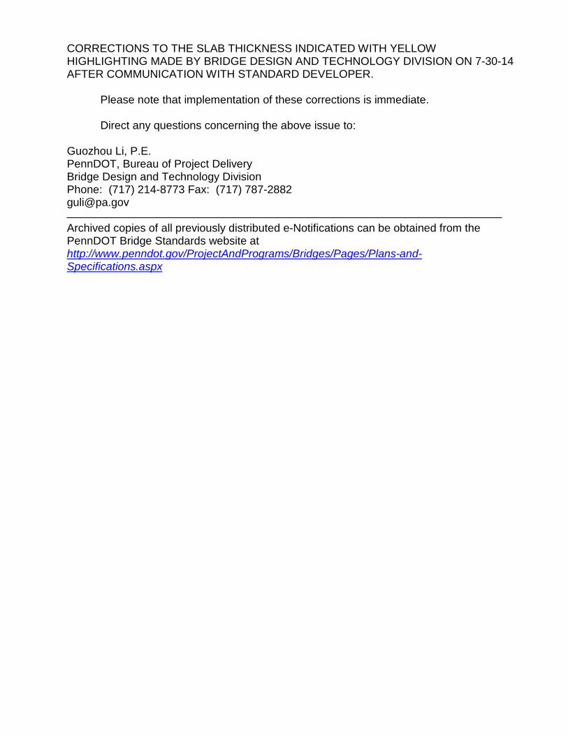
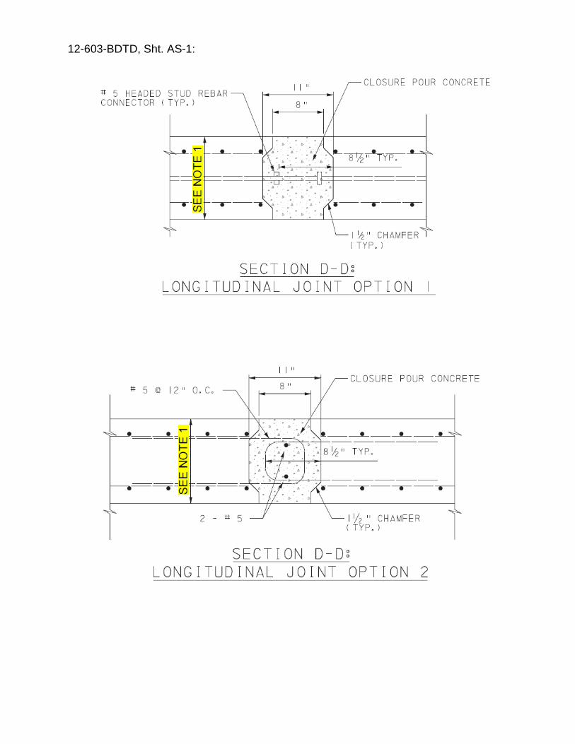
Shts. AS-1 & AS-2 - SECTION D-D (OPTIONS 1 & 2), B-B, E-E & F-F: replaced
approach slab thickness of 13” with “SEE NOTE 1” or “SEE NOTE 2” and added the statement shown below as a note on the right hand side of the sheets.
Shts. AS-3 & AS-4 – SECTIONS A-A: replaced approach slab thickness of 1’-3”
with “SEE NOTE 5” and added the statement shown below as a note on the right hand side of the sheets.
Sht. AS-5 - SECTION A-A & TYPICAL TRANSVERSE SECTION: replaced
approach slab thickness of 13” with “SEE NOTE 1” and added the statement shown below as a note on the right hand side of the sheet.
NOTE:
APPROACH SLAB THICKNESS IN ACCORDANCE WITH BD-628M OR A SMALLER THICKNESS MAY BE USED IF CONFIRMED BY DESIGN COMPUTATIONS WHICH TAKE INTO ACCOUNT THE HIGHER CONCRETE STRENGTH OF PRECAST CONCRETE.
Changes made to details are indicated with yellow highlighting on the five (5)
attached pages and the following statement has been added to the bottom of each drawing sheet:
CORRECTIONS TO THE SLAB THICKNESS INDICATED WITH YELLOW HIGHLIGHTING MADE BY BRIDGE DESIGN AND TECHNOLOGY DIVISION ON 7-30-14 AFTER COMMUNICATION WITH STANDARD DEVELOPER.
Please note that implementation of these corrections is immediate. Direct any questions concerning the above issue to:
Guozhou Li, P.E. PennDOT, Bureau of Project Delivery Bridge Design and Technology Division Phone: (717) 214-8773 Fax: (717) 787-2882 [email protected] Archived copies of all previously distributed e-Notifications can be obtained from the PennDOT Bridge Standards website at http://www.penndot.gov/ProjectAndPrograms/Bridges/Pages/Plans-and-Specifications.aspx
12-603-BDTD, Sht. AS-1:
12-603-BDTD, Sht. AS-2:
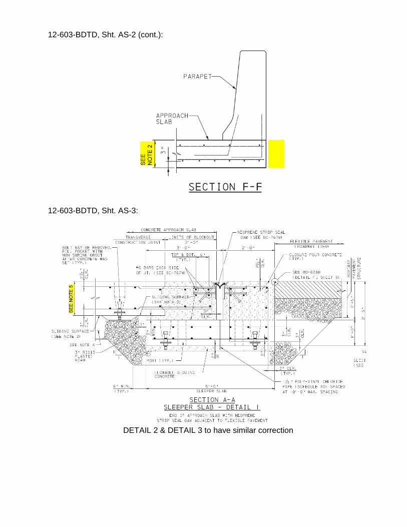
12-603-BDTD, Sht. AS-2 (cont.):
12-603-BDTD, Sht. AS-3:
DETAIL 2 & DETAIL 3 to have similar correction
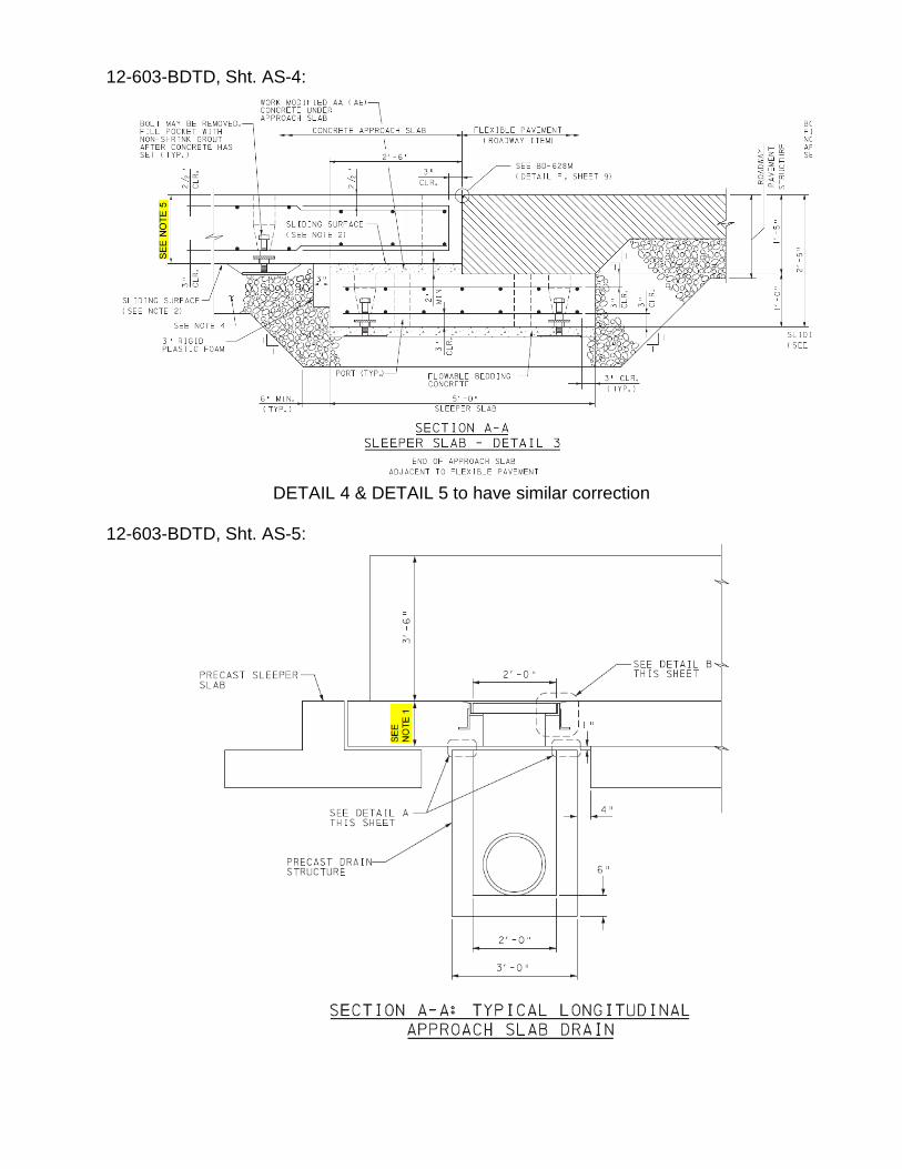
12-603-BDTD, Sht. AS-4:
DETAIL 4 & DETAIL 5 to have similar correction
12-603-BDTD, Sht. AS-5:
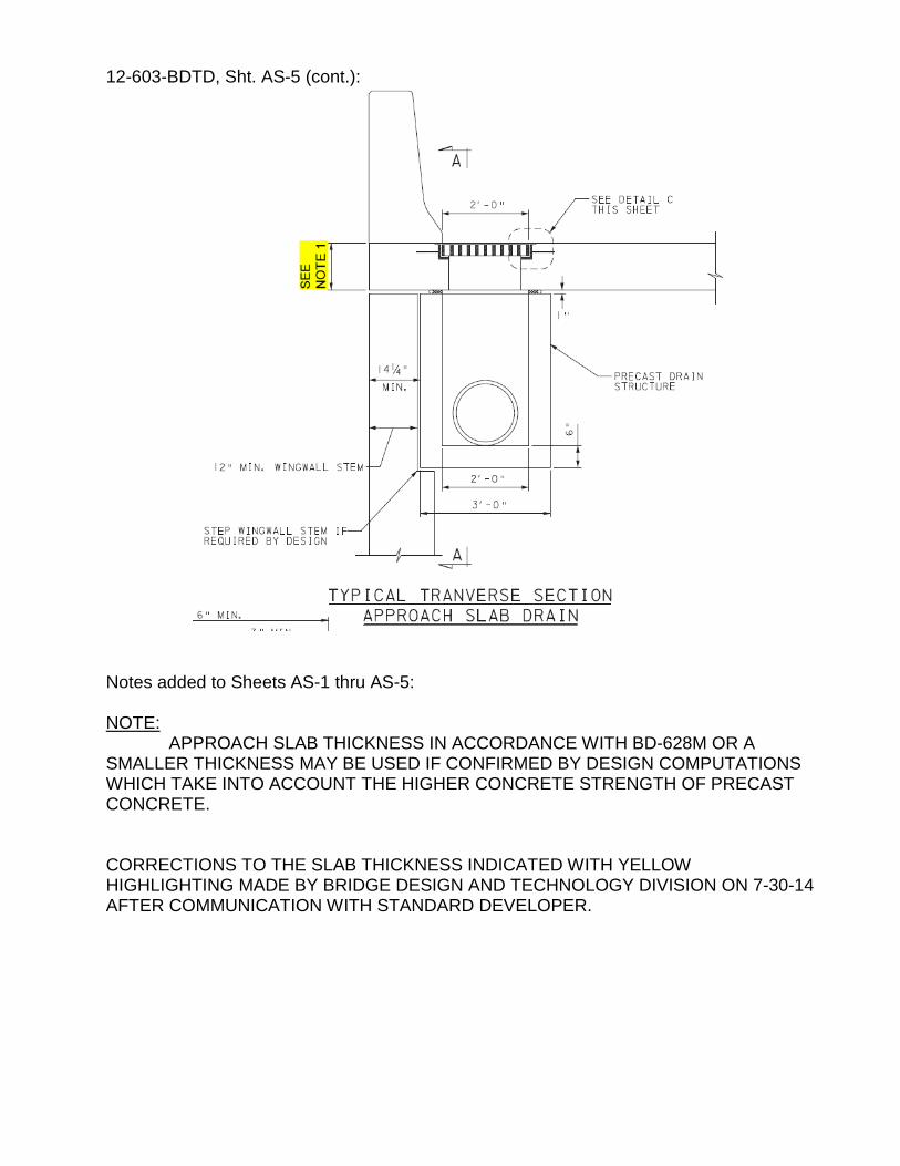
12-603-BDTD, Sht. AS-5 (cont.):
Notes added to Sheets AS-1 thru AS-5: NOTE:
APPROACH SLAB THICKNESS IN ACCORDANCE WITH BD-628M OR A SMALLER THICKNESS MAY BE USED IF CONFIRMED BY DESIGN COMPUTATIONS WHICH TAKE INTO ACCOUNT THE HIGHER CONCRETE STRENGTH OF PRECAST CONCRETE. CORRECTIONS TO THE SLAB THICKNESS INDICATED WITH YELLOW HIGHLIGHTING MADE BY BRIDGE DESIGN AND TECHNOLOGY DIVISION ON 7-30-14 AFTER COMMUNICATION WITH STANDARD DEVELOPER.
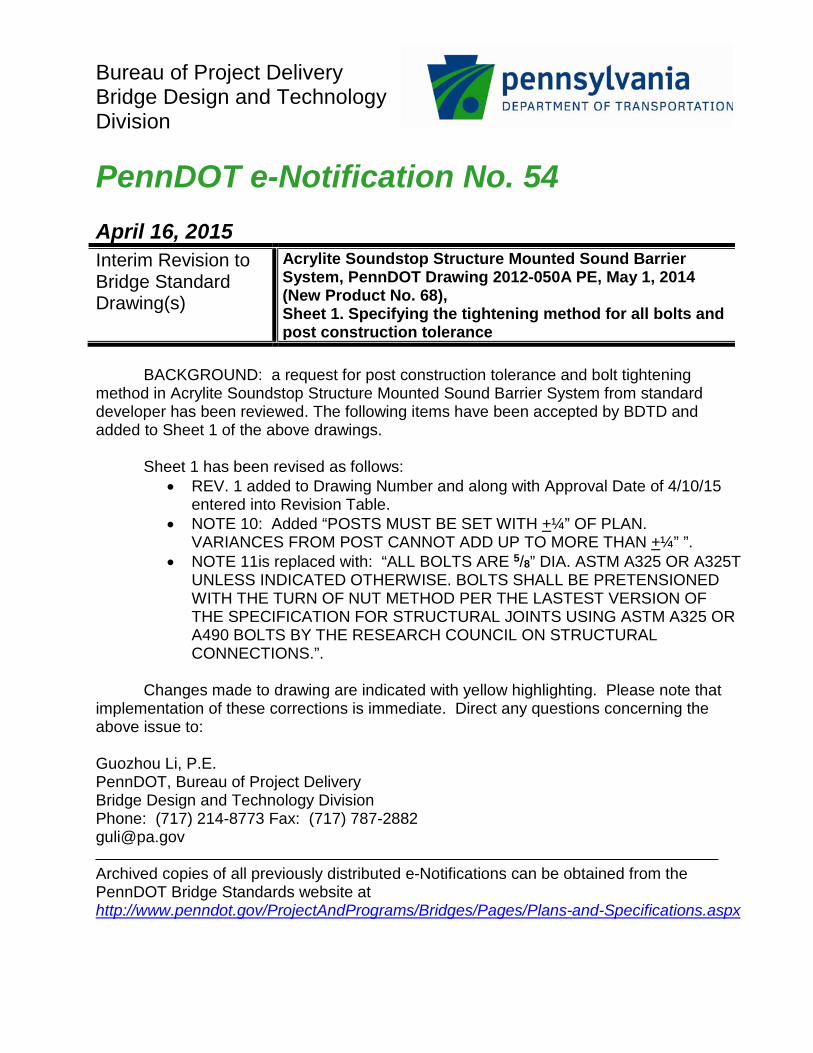
Bureau of Project Delivery Bridge Design and Technology Division PennDOT e-Notification No. 54 April 16, 2015 Interim Revision to Bridge Standard Drawing(s)
Acrylite Soundstop Structure Mounted Sound Barrier System, PennDOT Drawing 2012-050A PE, May 1, 2014 (New Product No. 68), Sheet 1. Specifying the tightening method for all bolts and post construction tolerance
BACKGROUND: a request for post construction tolerance and bolt tightening
method in Acrylite Soundstop Structure Mounted Sound Barrier System from standard developer has been reviewed. The following items have been accepted by BDTD and added to Sheet 1 of the above drawings.
Sheet 1 has been revised as follows:
• REV. 1 added to Drawing Number and along with Approval Date of 4/10/15 entered into Revision Table.
• NOTE 10: Added “POSTS MUST BE SET WITH +¼” OF PLAN. VARIANCES FROM POST CANNOT ADD UP TO MORE THAN +¼” ”.
• NOTE 11is replaced with: “ALL BOLTS ARE 5/8” DIA. ASTM A325 OR A325T UNLESS INDICATED OTHERWISE. BOLTS SHALL BE PRETENSIONED WITH THE TURN OF NUT METHOD PER THE LASTEST VERSION OF THE SPECIFICATION FOR STRUCTURAL JOINTS USING ASTM A325 OR A490 BOLTS BY THE RESEARCH COUNCIL ON STRUCTURAL CONNECTIONS.”.
Changes made to drawing are indicated with yellow highlighting. Please note that
implementation of these corrections is immediate. Direct any questions concerning the above issue to: Guozhou Li, P.E. PennDOT, Bureau of Project Delivery Bridge Design and Technology Division Phone: (717) 214-8773 Fax: (717) 787-2882 [email protected] Archived copies of all previously distributed e-Notifications can be obtained from the PennDOT Bridge Standards website at http://www.penndot.gov/ProjectAndPrograms/Bridges/Pages/Plans-and-Specifications.aspx
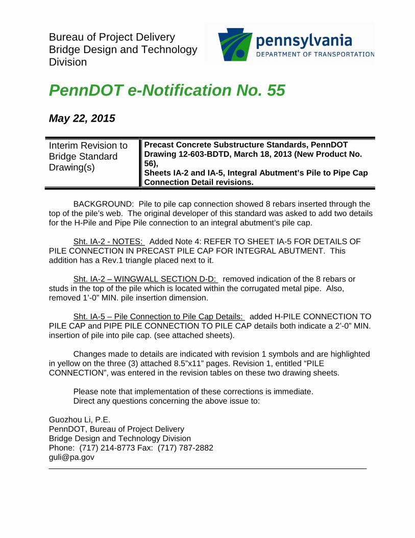
Bureau of Project Delivery Bridge Design and Technology Division PennDOT e-Notification No. 55 May 22, 2015 Interim Revision to Bridge Standard Drawing(s)
Precast Concrete Substructure Standards, PennDOT Drawing 12-603-BDTD, March 18, 2013 (New Product No. 56), Sheets IA-2 and IA-5, Integral Abutment’s Pile to Pipe Cap Connection Detail revisions.
BACKGROUND: Pile to pile cap connection showed 8 rebars inserted through the
top of the pile’s web. The original developer of this standard was asked to add two details for the H-Pile and Pipe Pile connection to an integral abutment’s pile cap.
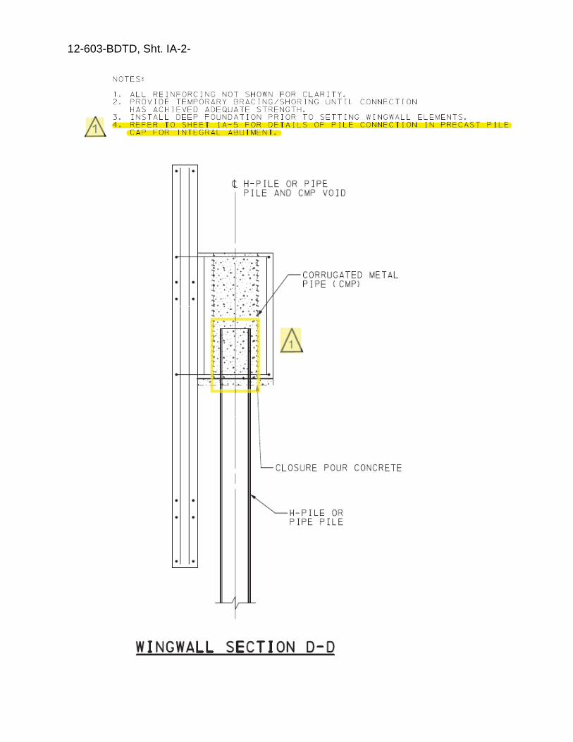
Sht. IA-2 - NOTES: Added Note 4: REFER TO SHEET IA-5 FOR DETAILS OF
PILE CONNECTION IN PRECAST PILE CAP FOR INTEGRAL ABUTMENT. This addition has a Rev.1 triangle placed next to it.
Sht. IA-2 – WINGWALL SECTION D-D: removed indication of the 8 rebars or
studs in the top of the pile which is located within the corrugated metal pipe. Also, removed 1’-0” MIN. pile insertion dimension.
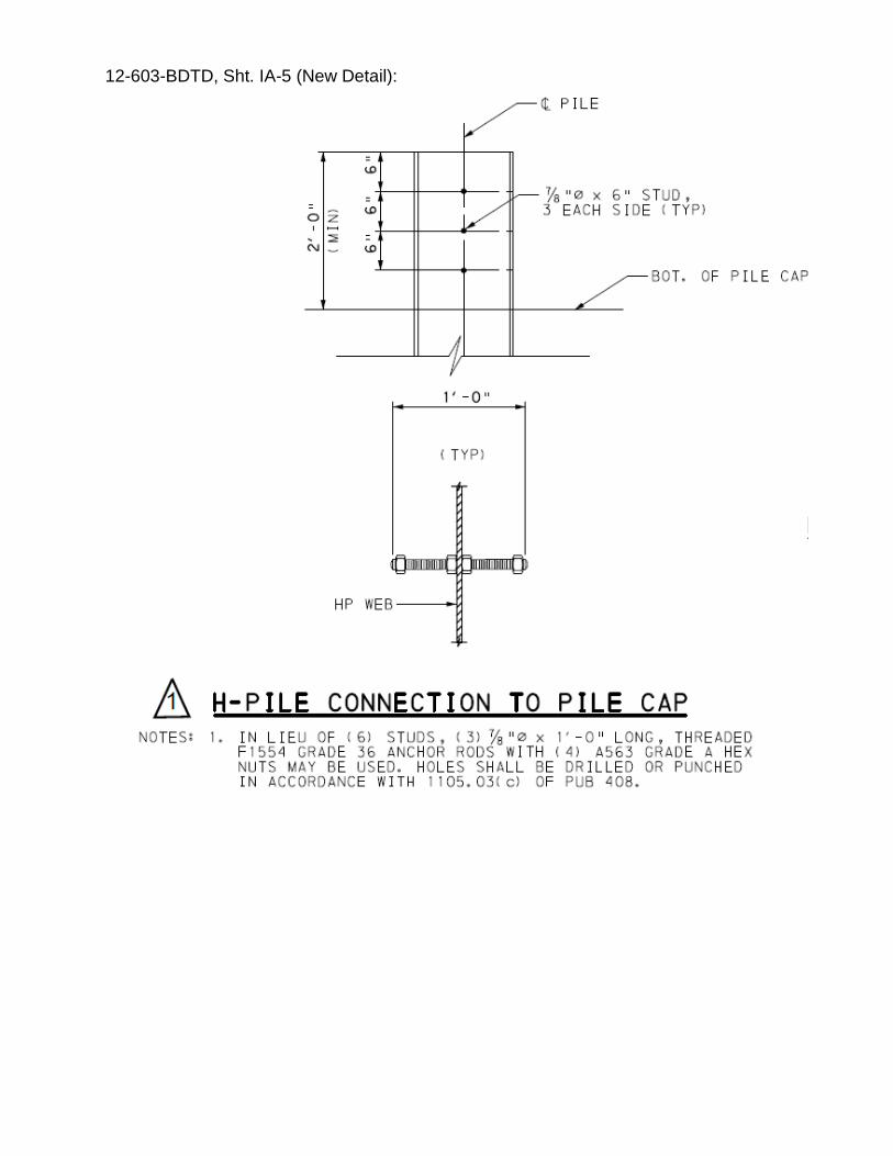
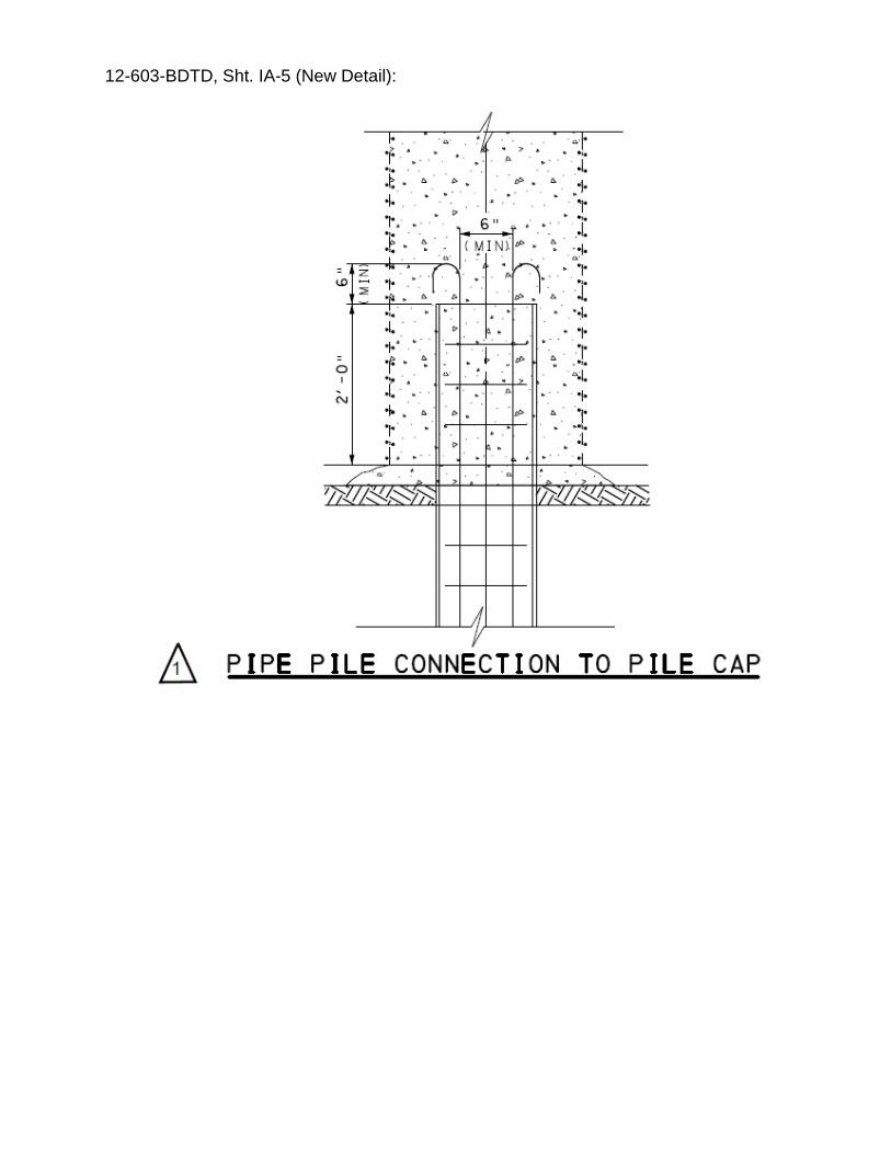
Sht. IA-5 – Pile Connection to Pile Cap Details: added H-PILE CONNECTION TO
PILE CAP and PIPE PILE CONNECTION TO PILE CAP details both indicate a 2’-0” MIN. insertion of pile into pile cap. (see attached sheets).
Changes made to details are indicated with revision 1 symbols and are highlighted
in yellow on the three (3) attached 8.5”x11” pages. Revision 1, entitled “PILE CONNECTION”, was entered in the revision tables on these two drawing sheets.
Please note that implementation of these corrections is immediate. Direct any questions concerning the above issue to:
Guozhou Li, P.E. PennDOT, Bureau of Project Delivery Bridge Design and Technology Division Phone: (717) 214-8773 Fax: (717) 787-2882 [email protected]

Archived copies of all previously distributed e-Notifications can be obtained from the PennDOT Bridge Standards website at http://www.penndot.gov/ProjectAndPrograms/Bridges/Pages/Plans-and-Specifications.aspx
12-603-BDTD, Sht. IA-2-
12-603-BDTD, Sht. IA-5 (New Detail):
12-603-BDTD, Sht. IA-5 (New Detail):
Bureau of Project Delivery Bridge Design and Technology Division PennDOT e-Notification No. 57 June 6, 2016 Interim Revision to Bridge Standard Drawing(s)
Folded Steel Plate Girder System, PennDOT Drawing No. 14-604-BDTD, Sept. 2, 2014 (New Product No. 71), Sheets 1 & 2 – Folded Steel Plate Girder System – Correction of Steel Hardware Galvanization Notes.
BACKGROUND: It was recently pointed out to BDTD that the notes for galvanizing
the steel hardware needed to be corrected since they were requiring hardware to be hot dipped galvanized instead of mechanically galvanized in both the Design and Construction Specifications.
Sheets 1 – Design Specifications: In third column, 4th paragraph; replace HOT DIP GALVANIZED with EITHER HOT DIP GALVANIZED OR MECHANICALLY GALVANIZED. Also added (MECHANICALLY GALVANIZED) or (HOT DIP GALVANIZED) after the four hardware items listed. The corrected text is indicated with clouding in the attached 8½”x11” sheet. Sheets 2 – Construction Specifications: In first column, 5th paragraph; replace HOT DIP GALVANIZED with EITHER HOT DIP GALVANIZED OR MECHANICALLY GALVANIZED. Also added (MECHANICALLY GALVANIZED) or (HOT DIP GALVANIZED) after four hardware items listed. The corrected text is indicated with clouding in the attached 8½”x11” sheet. Please note that implementation of these corrections is immediate. Direct any questions concerning the above issue to:
Guozhou Li, P.E. PennDOT, Bureau of Project Delivery Bridge Design and Technology Division Phone: (717) 214-8773 Fax: (717) 787-2882 [email protected] Archived copies of all previously distributed e-Notifications can be obtained from the PENNDOT Bridge Standards website at http://www.penndot.gov/ProjectAndPrograms/Bridges/Pages/Plans-and-Specifications.aspx
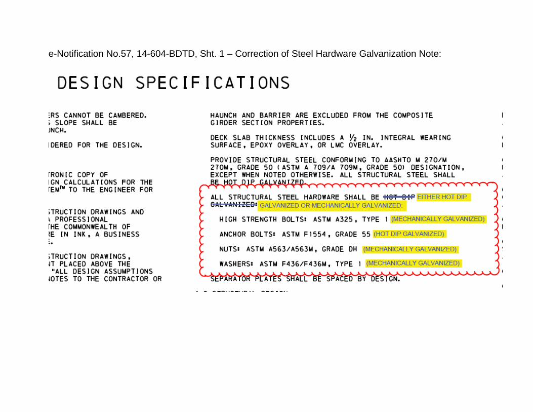
e-Notification No.57, 14-604-BDTD, Sht. 1 – Correction of Steel Hardware Galvanization Note:
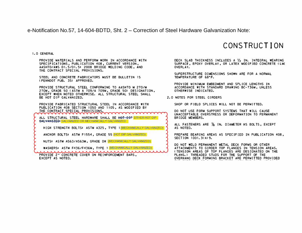
e-Notification No.57, 14-604-BDTD, Sht. 2 – Correction of Steel Hardware Galvanization Note:
Bureau of Project Delivery Bridge Design and Technology Division PennDOT e-Notification No. 70 Aug. 23, 2017 Interim Revision to Bridge Standard Drawing(s)
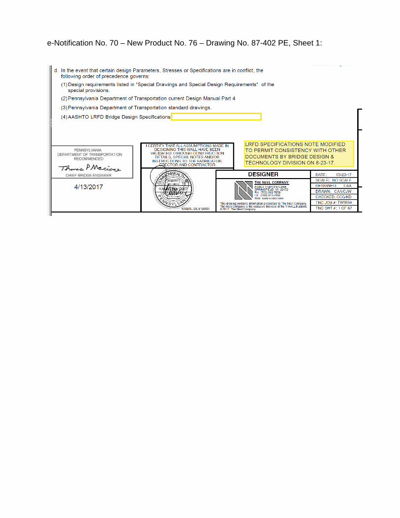
PREFABRICATED T-WALL RETAINING WALL SYSTEM, PennDOT Drawing No. 87-402 PE, April 13, 2017 (New Product No. 76), Sheet 1 – Correction of Note regarding LRFD Specifications.
BACKGROUND: The general note which lists the AASHTO LRFD Specifications
was listing a specific Edition and Interim revisions which might cause an inconsistency with other documents.
Sheet 1, T-WALL Design Specifications: Revise 3.0 Design section note 3.0.d(4) as indicated below: Current appearance: (4) AASHTO LRFD Bridge Design Specifications, fifth edition with 2010 revisions
New appearance: (4) AASHTO LRFD Bridge Design Specifications
A text box describing this correction with yellow highlighting is being added next to
the drawing border.
The above referenced modification is provided on the attached 8½”x11” sheet.
Please note to implement this change immediately. Direct any questions concerning the above issue to: Guozhou Li, P.E. PennDOT, Bureau of Project Delivery / Bridge Design and Technology Division Phone: (717) 214-8773 Fax: (717) 787-2882 [email protected] Archived copies of all previously distributed e-Notifications can be obtained from the PennDOT Bridge Standards website at http://www.penndot.gov/ProjectAndPrograms/Bridges/Pages/Plans-and-Specifications.aspx
e-Notification No. 70 – New Product No. 76 – Drawing No. 87-402 PE, Sheet 1:
Bureau of Project Delivery Bridge Design and Technology Division
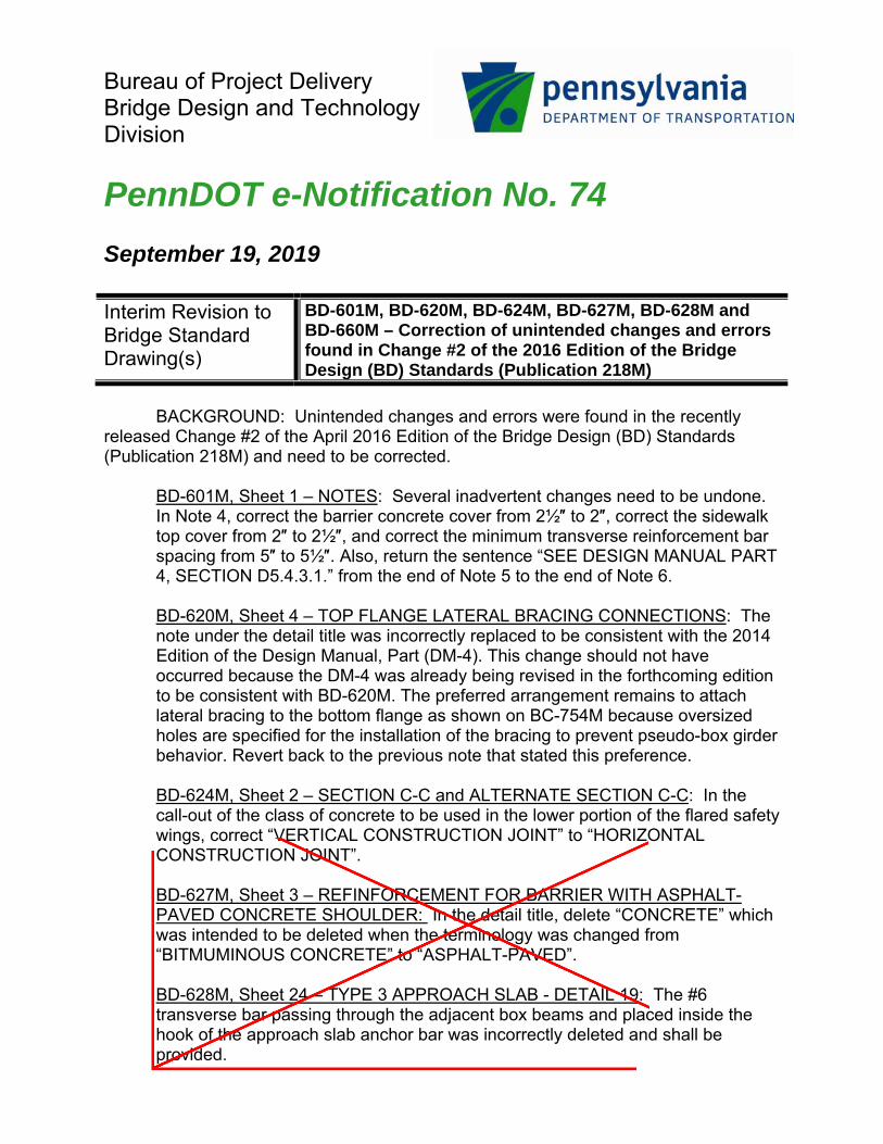
PennDOT e-Notification No. 74 September 19, 2019 Interim Revision to Bridge Standard Drawing(s)
BD-601M, BD-620M, BD-624M, BD-627M, BD-628M and BD-660M – Correction of unintended changes and errors found in Change #2 of the 2016 Edition of the Bridge Design (BD) Standards (Publication 218M)
BACKGROUND: Unintended changes and errors were found in the recently
released Change #2 of the April 2016 Edition of the Bridge Design (BD) Standards (Publication 218M) and need to be corrected.
BD-601M, Sheet 1 – NOTES: Several inadvertent changes need to be undone. In Note 4, correct the barrier concrete cover from 2½″ to 2″, correct the sidewalk top cover from 2″ to 2½″, and correct the minimum transverse reinforcement bar spacing from 5″ to 5½″. Also, return the sentence “SEE DESIGN MANUAL PART 4, SECTION D5.4.3.1.” from the end of Note 5 to the end of Note 6. BD-620M, Sheet 4 – TOP FLANGE LATERAL BRACING CONNECTIONS: The note under the detail title was incorrectly replaced to be consistent with the 2014 Edition of the Design Manual, Part (DM-4). This change should not have occurred because the DM-4 was already being revised in the forthcoming edition to be consistent with BD-620M. The preferred arrangement remains to attach lateral bracing to the bottom flange as shown on BC-754M because oversized holes are specified for the installation of the bracing to prevent pseudo-box girder behavior. Revert back to the previous note that stated this preference. BD-624M, Sheet 2 – SECTION C-C and ALTERNATE SECTION C-C: In the call-out of the class of concrete to be used in the lower portion of the flared safety wings, correct “VERTICAL CONSTRUCTION JOINT” to “HORIZONTAL CONSTRUCTION JOINT”. BD-627M, Sheet 3 – REFINFORCEMENT FOR BARRIER WITH ASPHALT-PAVED CONCRETE SHOULDER: In the detail title, delete “CONCRETE” which was intended to be deleted when the terminology was changed from “BITMUMINOUS CONCRETE” to “ASPHALT-PAVED”. BD-628M, Sheet 24 – TYPE 3 APPROACH SLAB - DETAIL 19: The #6 transverse bar passing through the adjacent box beams and placed inside the hook of the approach slab anchor bar was incorrectly deleted and shall be provided.
Rectangle
Rectangle
Line
Line
Line
Line
Text Box
deleted by Change 3 (2/19/2021) to the BD Standards, April 2016 Edition
Text Box
deleted by Change 3 (2/19/2021) to the BD Standards, April 2016 Edition
Text Box
Portions of this e-Notification deleted by Change 3 (2/19/2021) to BD Standards, 2016 Edition
PennDOT e-Notification No. 74 September 19, 2019
BD-660M, Sheet 1 – NOTES: In Note 1, after “WORK QUALITY” delete “MANSHIP” which was intended to be deleted when the terminology was changed from “WORKMANSHIP” to “WORK QUALITY”. These corrections are indicated with red markups on the six attached 8½”x11”
sheets. Please note that implement of these corrections is immediate. Direct any
questions concerning the above issue to: Guozhou Li, P.E. PennDOT, Bureau of Project Delivery / Bridge Design and Technology Division Phone: (717) 214-8773 Fax: (717) 787-2882 [email protected] Archived copies of all previously distributed e-Notifications can be obtained from the PennDOT Bridge Standards website at http://www.penndot.gov/ProjectAndPrograms/Bridges/Pages/Plans-and-Specifications.aspx
Rectangle
Text Box
deleted by Change 3 (2/19/2021) to the BD Standards, April 2016 Edition
Line
Line
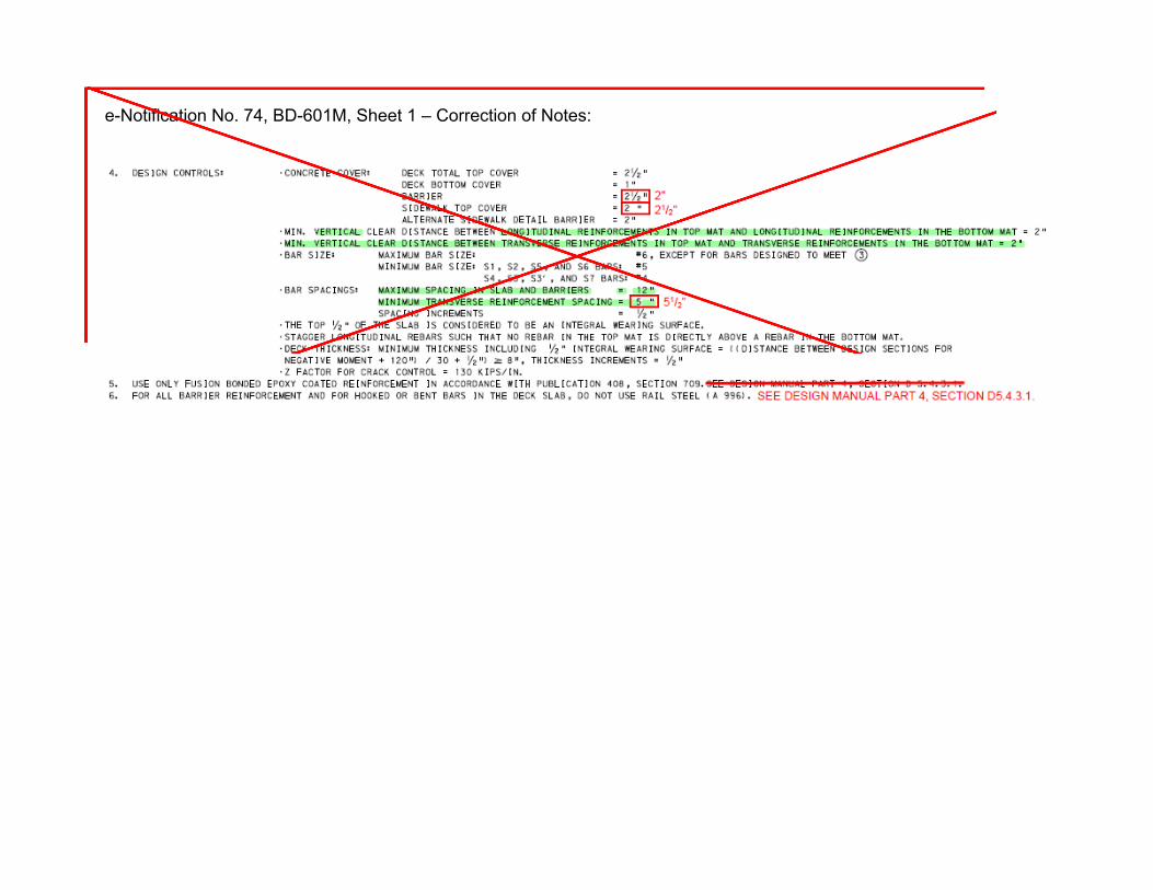
e-Notification No. 74, BD-601M, Sheet 1 – Correction of Notes:
Rectangle
Line
Line
Text Box
deleted by Change 3 (2/19/2021) to the BD Standards, April 2016 Edition

e-Notification No. 74, BD-620M, Sheet 4 – Reversion of Lateral Bracing Note:
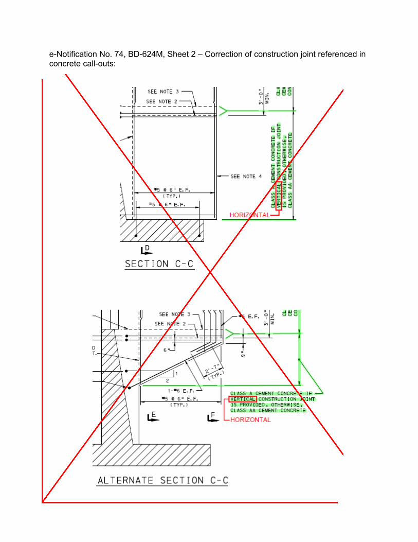
e-Notification No. 74, BD-624M, Sheet 2 – Correction of construction joint referenced in concrete call-outs:
Line
Line
Text Box
deleted by Change 3 (2/19/2021) to the BD Standards, April 2016 Edition
Rectangle
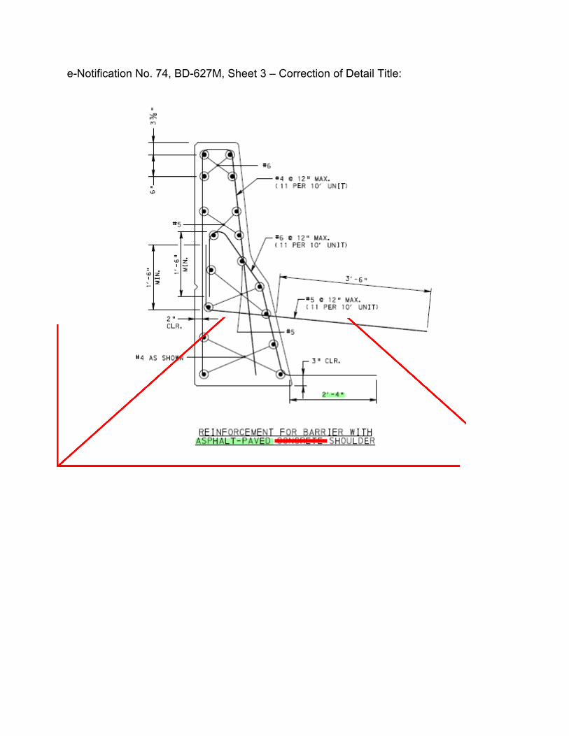
e-Notification No. 74, BD-627M, Sheet 3 – Correction of Detail Title:
Text Box
deleted by Change 3 (2/19/2021) to the BD Standards, April 2016 Edition
Rectangle
Line
Line
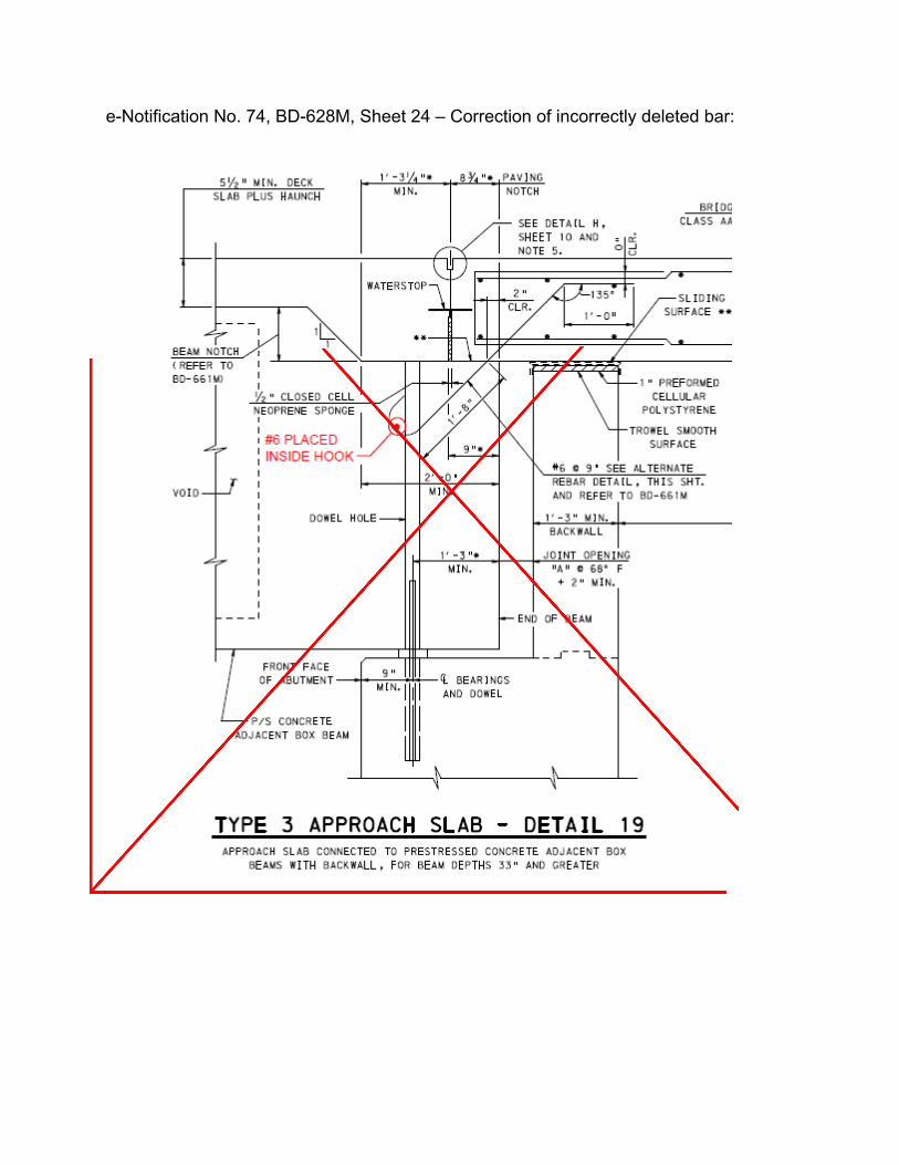
e-Notification No. 74, BD-628M, Sheet 24 – Correction of incorrectly deleted bar:
Text Box
deleted by Change 3 (2/19/2021) to the BD Standards, April 2016 Edition
Rectangle
Line
Line

e-Notification No. 74, BD-660M, Sheet 1 – Correction of Note 1:
Text Box
deleted by Change 3 (2/19/2021) to the BD Standards, April 2016 Edition
Rectangle
Line
Line

Bureau of Project Delivery Bridge Design and Technology Division
PennDOT e-Notification No. 75 April 29, 2020 Interim Revision to Bridge Standard Drawing(s)
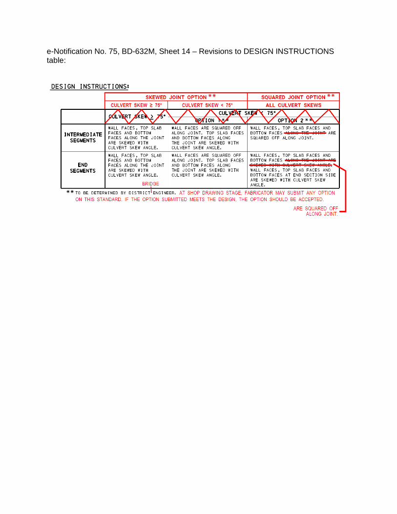
BD-632M, R.C. BOX CULVERT, August 30, 2019, Sheet 14 – SEGMENT JOINT DETAILS: Correction of the applicability of the Precast R.C. Box Culvert configuration with squared segment joints.
BACKGROUND: Precast R.C. Box Culvert Segment Joint Details were added to
BD-632M in Change No. 2 to the April 2016 Edition of the Standards. The configuration with squared segment joints was labeled as being a second option for culverts with skew angles less than 75°. However, squared joints may be considered for all culverts, limited only by the minimum skew angle for which the end segments can be fabricated. In fact, due to post-tensioning effects, squared joints are preferred though not required.
Additionally, clarification is added to indicate that the fabricator may submit shop drawings for any of the options on this standard that meet the design.
SKEW ANGLE < 75° - OPTION 2 detail: Renamed detail “SQUARED JOINT OPTION (ALL SKEW ANGLES)”. SKEW ANGLE ≥ 75° detail: Added “SKEWED JOINT OPTION” to detail name. SKEW ANGLE < 75° - OPTION 1 detail: Added “SKEWED JOINT OPTION” to beginning of detail name and removed “- OPTION 1”. DESIGN INSTRUCTIONS table: Revised the column headings to correct the applicability of the three options; corrected the segment descriptions for the Squared Joint Option; and expanded the note to clarify the fabricator’s options.
These updates are indicated with red markups on the attached 8½”x11” sheets. Please note that implementation of these updates is immediate. Direct any
questions concerning the above issue to: Guozhou Li, P.E. PennDOT, Bureau of Project Delivery / Bridge Design and Technology Division Phone: (717) 214-8773 | Fax: (717) 787-2882 [email protected]
Archived copies of all previously distributed e-Notifications can be obtained from the Bridge “Plans, Standards and Specifications” page on the Department’s website: https://www.penndot.gov/ProjectAndPrograms/Bridges/Pages/Plans,-Standards-and-Specifications.aspx
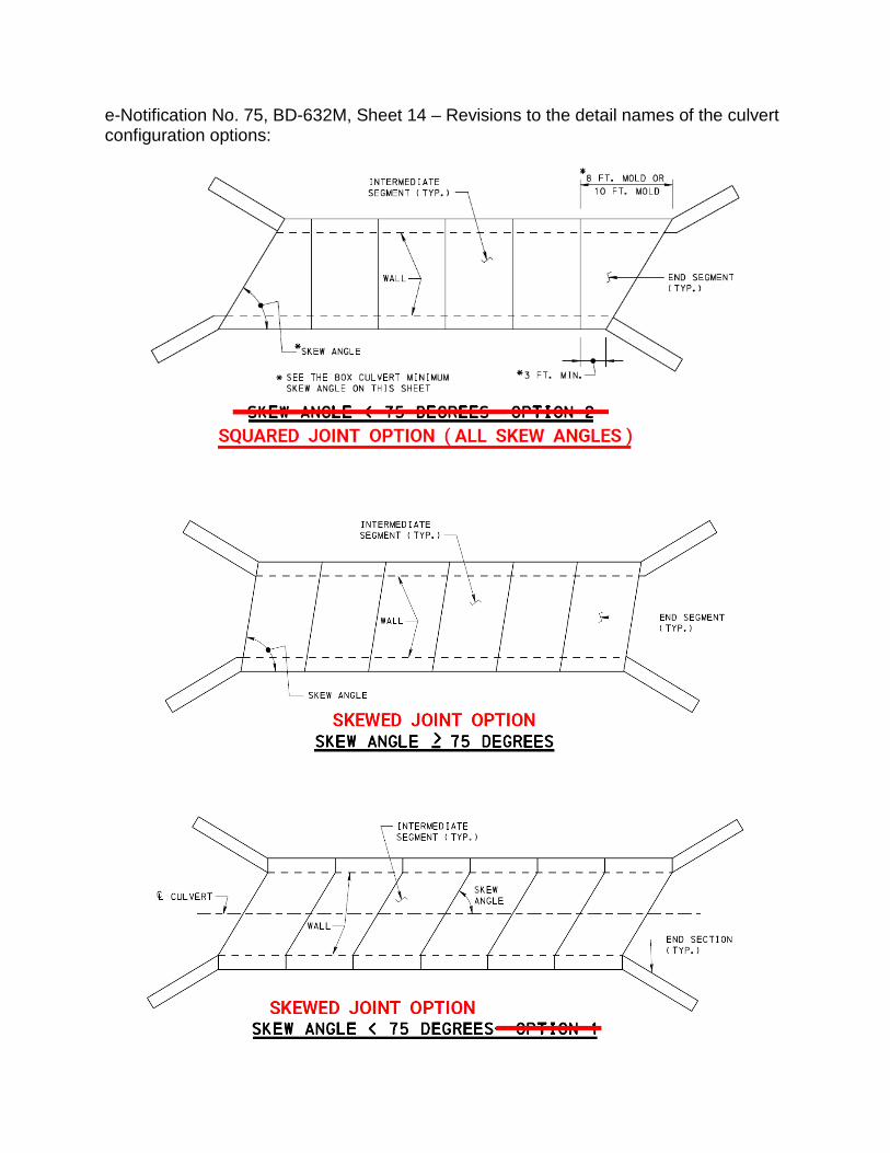
e-Notification No. 75, BD-632M, Sheet 14 – Revisions to the detail names of the culvert configuration options:
e-Notification No. 75, BD-632M, Sheet 14 – Revisions to DESIGN INSTRUCTIONS table:
Bureau of Project Delivery Bridge Design and Technology Division
PennDOT e-Notification No. 76 June 26, 2020 Interim Revision to Bridge Standard Drawing(s)
New e-Notification Server and Email Addresses; Subscription Renewal Required
BACKGROUND: On June 26, 2020 the PennDOT Bridge Publications e-Notification
system will be switched to a new server. This is the last e-Notification you will receive from the old server [email protected].
The new e-Notification server will use the following email addresses: Send questions to the list:
[email protected] Send blank email to subscribe:
[email protected] Send blank email to unsubscribe:
[email protected] In the new email addresses, “bqad-pubs” now becomes “BdtdPubs” and “listserver” becomes “listserv”.
ACTION ITEMS: Starting on June 26, 2020, if you want to continue to receive
e-Notifications you will need to renew your subscription by sending a blank email to [email protected] to subscribe to the new server. You must then reply to the confirmation email with “OK” in the body of the message to complete your subscription.
If you do not see the confirmation email in your inbox, please look for it in your spam or junk folder. If you locate the confirmation email in your spam or junk folder, then it is recommended that you add a rule to your email software to allow all emails from “@listserv.bakerprojects.com” to be delivered to your inbox.
Direct any questions concerning the above issue to: Nikki Krise PennDOT, Bureau of Project Delivery / Bridge Design and Technology Division Phone: (717) 783-6416 | Fax: (717) 787-2882 [email protected]
Archived copies of all previously distributed e-Notifications can be obtained from the Bridge “Plans, Standards and Specifications” page on the Department’s website: https://www.penndot.gov/ProjectAndPrograms/Bridges/Pages/Plans,-Standards-and-Specifications.aspx
Bureau of Project Delivery Bridge Design and Technology Division
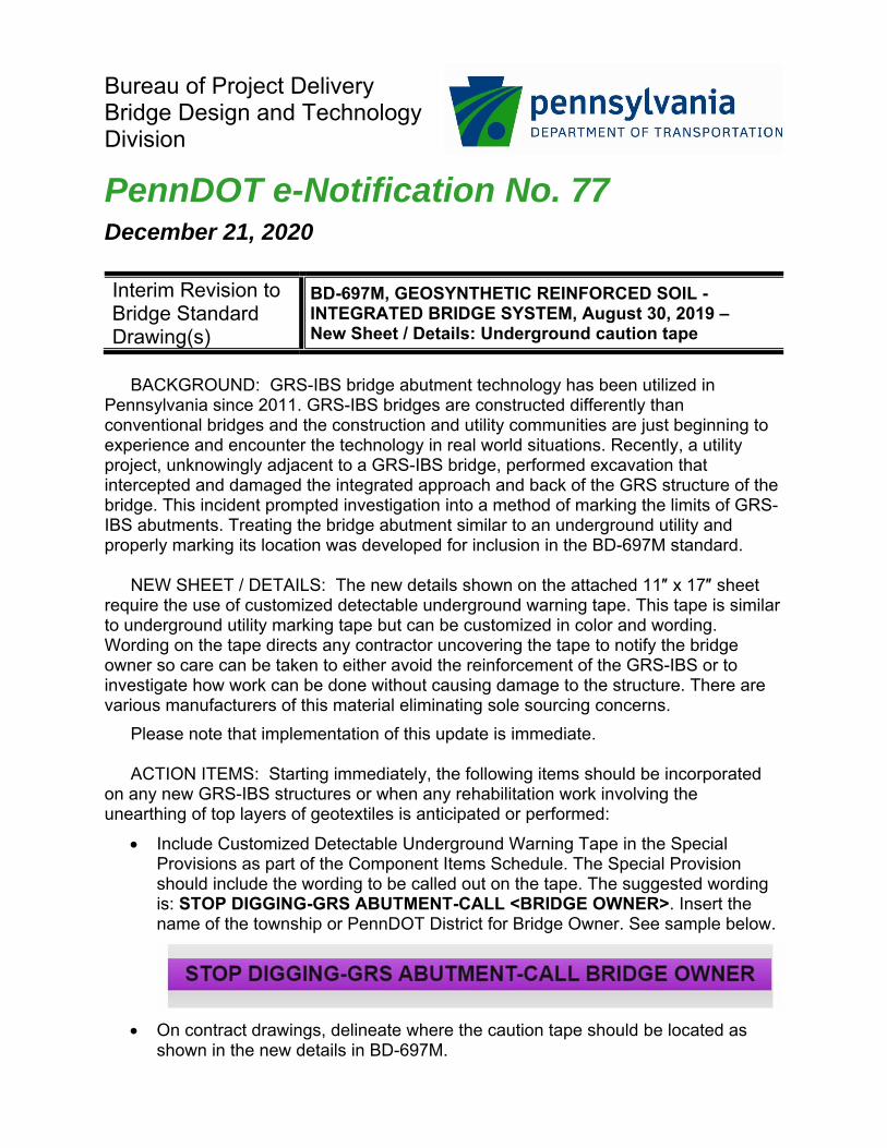
PennDOT e-Notification No. 77 December 21, 2020 Interim Revision to Bridge Standard Drawing(s)
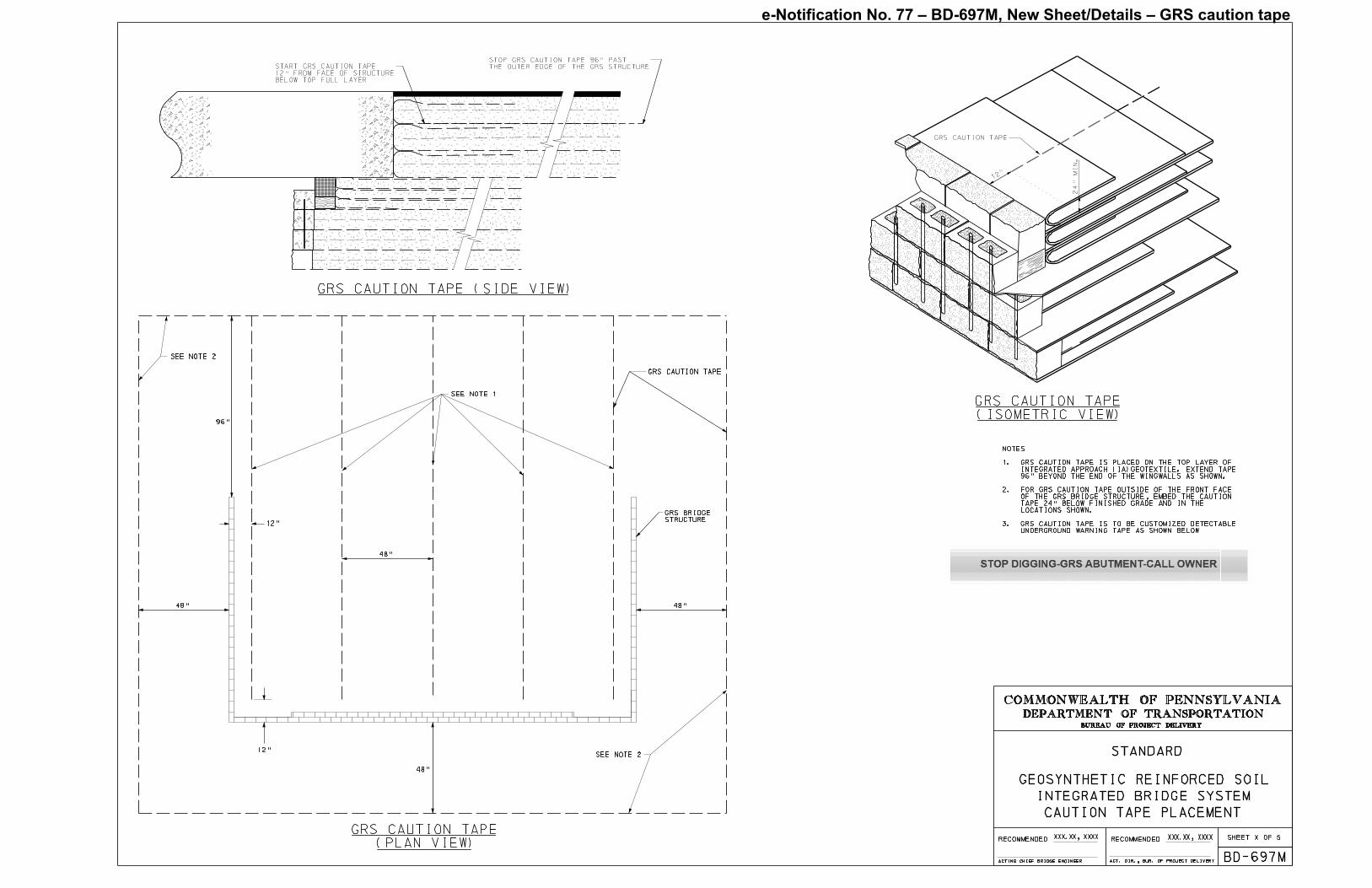
BD-697M, GEOSYNTHETIC REINFORCED SOIL - INTEGRATED BRIDGE SYSTEM, August 30, 2019 – New Sheet / Details: Underground caution tape
BACKGROUND: GRS-IBS bridge abutment technology has been utilized in
Pennsylvania since 2011. GRS-IBS bridges are constructed differently than conventional bridges and the construction and utility communities are just beginning to experience and encounter the technology in real world situations. Recently, a utility project, unknowingly adjacent to a GRS-IBS bridge, performed excavation that intercepted and damaged the integrated approach and back of the GRS structure of the bridge. This incident prompted investigation into a method of marking the limits of GRS-IBS abutments. Treating the bridge abutment similar to an underground utility and properly marking its location was developed for inclusion in the BD-697M standard.
NEW SHEET / DETAILS: The new details shown on the attached 11″ x 17″ sheet
require the use of customized detectable underground warning tape. This tape is similar to underground utility marking tape but can be customized in color and wording. Wording on the tape directs any contractor uncovering the tape to notify the bridge owner so care can be taken to either avoid the reinforcement of the GRS-IBS or to investigate how work can be done without causing damage to the structure. There are various manufacturers of this material eliminating sole sourcing concerns.
Please note that implementation of this update is immediate. ACTION ITEMS: Starting immediately, the following items should be incorporated
on any new GRS-IBS structures or when any rehabilitation work involving the unearthing of top layers of geotextiles is anticipated or performed:
Include Customized Detectable Underground Warning Tape in the Special Provisions as part of the Component Items Schedule. The Special Provision should include the wording to be called out on the tape. The suggested wording is: STOP DIGGING-GRS ABUTMENT-CALL <BRIDGE OWNER>. Insert the name of the township or PennDOT District for Bridge Owner. See sample below.
On contract drawings, delineate where the caution tape should be located as
shown in the new details in BD-697M.
As part of the preliminary design discussion, designers should discuss with owners
the potential for future utilities in the project site. Owners of GRS-IBS bridges should be very aware of utility work in the vicinity of the bridge and advise the excavation company accordingly in order to protect the structure.
Direct any questions concerning the above issue to: Kristin Langer, P.E. PennDOT, Bureau of Project Delivery / Bridge Design and Technology Division Phone: (717) 787-7506 [email protected]
Archived copies of all previously distributed e-Notifications can be obtained from the Bridge “Plans, Standards and Specifications” page on the Department’s website: https://www.penndot.gov/ProjectAndPrograms/Bridges/Pages/Plans,-Standards-and-Specifications.aspx
e-Notification No. 77 – BD-697M, New Sheet/Details – GRS caution tape
Bureau of Project Delivery Bridge Design and Technology Division
PennDOT e-Notification No. 78 March 3, 2021 Interim Revision to Bridge Standard Drawing(s)
Revisions to the BD Standards (Pub. 218M) and BC Standards (Pub. 219M) for MASH 2016 compliance
The Bureau of Project Delivery has released Change 3 to the April 2016 Edition of
the Bridge Design Standards, BD-600M Series (Pub. 218M) and Change 3 to the September 2016 Edition of the Bridge Construction Standards, BC-700M Series (Pub. 219M), both dated February 19, 2021. (Note: Change 7 to June 2010 Edition of Roadway Construction Standards (Pub. 72M) was also part of this release.)
These changes contain revisions related to compliance with the AASHTO Manual for
Assessing Safety Hardware (MASH 2016). The revised standards have been incorporated into the updated publications that are
available from the PennDOT website on either the Forms, Publications, and Maps webpage or the Bridge Plans, Standards and Specifications webpage. The index sheets in these Publications indicate which standards have been revised as part of Change 3. The transmittal letters for these Publications include a description of the changes and Change 3 revisions are indicated by light blue highlighting.
These standards may be used immediately and can be adopted as soon as practical
on new and existing designs without affecting letting schedules. However, projects with T.S.&L. submissions after July 1, 2021 and projects let after April 1, 2022 shall incorporate these standards.
NOTE: Revisions to Bridge Structure Mounted Guiderail (SMGR) will be issued in a
later change package. Therefore, continue to use the current standards for projects that use SMGR.
Direct any questions concerning the above issue to: Guozhou Li, P.E. PennDOT, Bureau of Project Delivery / Bridge Design and Technology Division Phone: (717) 214-8773 | [email protected]
Archived copies of all previously distributed e-Notifications can be obtained from the Bridge “Plans, Standards and Specifications” page on the Department’s website: https://www.penndot.gov/ProjectAndPrograms/Bridges/Pages/Plans,-Standards-and-Specifications.aspx
Archived copies of all previously distributed e-Notifications can be obtained from the Bridge “Plans, Standards and Specifications” page on the Department’s website: https://www.penndot.gov/ProjectAndPrograms/Bridges/Pages/Plans,-Standards-and-Specifications.aspx
Bureau of Project Delivery Bridge Design and Technology Division
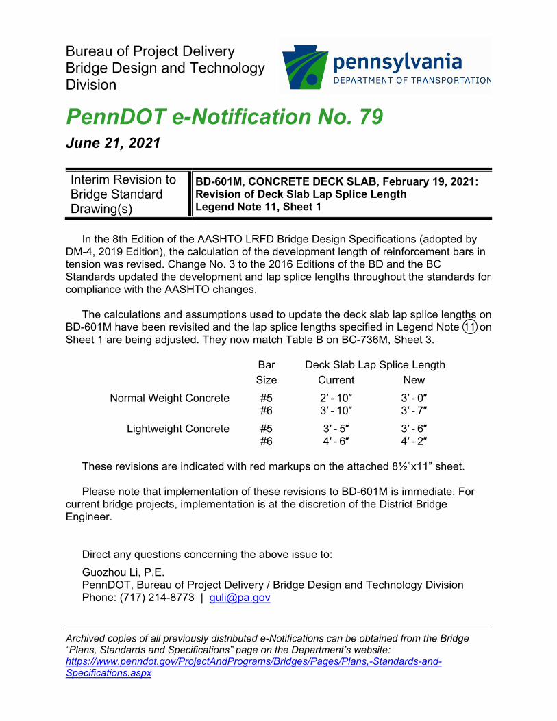
PennDOT e-Notification No. 79 June 21, 2021 Interim Revision to Bridge Standard Drawing(s)
BD-601M, CONCRETE DECK SLAB, February 19, 2021: Revision of Deck Slab Lap Splice Length Legend Note 11, Sheet 1
In the 8th Edition of the AASHTO LRFD Bridge Design Specifications (adopted by
DM-4, 2019 Edition), the calculation of the development length of reinforcement bars in tension was revised. Change No. 3 to the 2016 Editions of the BD and the BC Standards updated the development and lap splice lengths throughout the standards for compliance with the AASHTO changes.
The calculations and assumptions used to update the deck slab lap splice lengths on
BD-601M have been revisited and the lap splice lengths specified in Legend Note 11 on Sheet 1 are being adjusted. They now match Table B on BC-736M, Sheet 3.
Bar Deck Slab Lap Splice Length
Size Current New Normal Weight Concrete #5 2′ - 10″ 3′ - 0″ #6 3′ - 10″ 3′ - 7″ Lightweight Concrete #5 3′ - 5″ 3′ - 6″ #6 4′ - 6″ 4′ - 2″ These revisions are indicated with red markups on the attached 8½”x11” sheet. Please note that implementation of these revisions to BD-601M is immediate. For
current bridge projects, implementation is at the discretion of the District Bridge Engineer.
Direct any questions concerning the above issue to: Guozhou Li, P.E. PennDOT, Bureau of Project Delivery / Bridge Design and Technology Division Phone: (717) 214-8773 | [email protected]
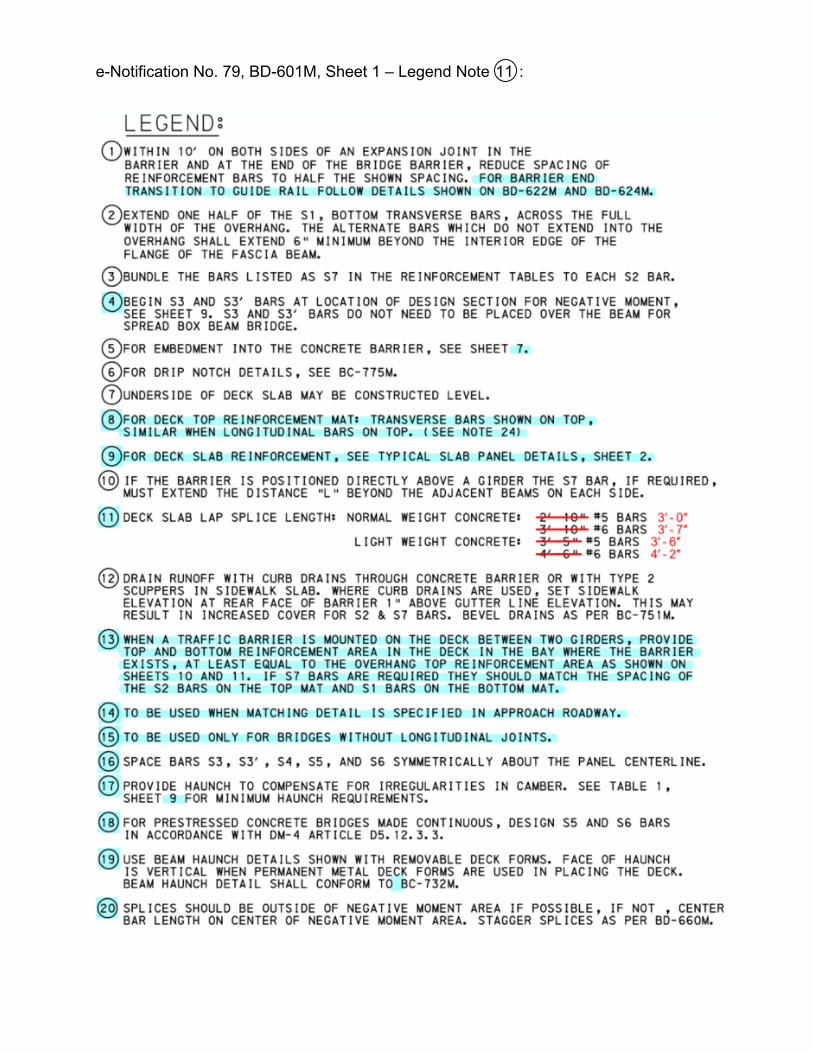
e-Notification No. 79, BD-601M, Sheet 1 – Legend Note 11 :