Action Trackchair NT Model Owner’s Manual
17
Revised ~ April 15, 2016 Page | 1 Action Trackchair NT Model Owner’s Manual
Transcript of Action Trackchair NT Model Owner’s Manual

Revised ~ April 15, 2016
Page | 1
Action Trackchair NT Model Owner’s Manual
Revised September 27, 2016 Page | 2
Action Manufacturing
Manufacturer: 1105 Lake Road
Marshall, MN 56258
507-532-5940
www.actiontrackchair.com
Exclusive
Australian 1/ 12 Robart Court
Importer: Narangba, Qld. 4504
Table of Contents Table of Contents……………………………………………………………………………………………………................................. 2
Introduction .................................................................................................................................................. 3
Safety ............................................................................................................................................................ 4
Operating the Action Trackchair ................................................................................................................... 5
Comfort Adjustments .................................................................................................................................... 6
Batteries and Charging……………..……………………………………………………………………….……………………...........7 & 8
Repair and Maintenance ............................................................................................................................... 9
Warranties .................................................................................................................................................. 10
Specifications .............................................................................................................................................. 11
Table 1: Hand Control Fault & Warning Indicators ............................................................................. 12 & 13
Australian Standards Requirements………………………………………………………………………………………………………14
Power and Control System Circuitry………………………………………………………………………………………………15 & 16

Revised September 27, 2016 Page | 3
Introduction
Welcome to the Action Trackchair Experience!
We at KCF Disability Engineering and Action Manufacturing want to make your experience the
best it can be.
Enclosed in this owner’s manual you’ll find information for the use and maintenance of your
Action Trackchair.
Thank you for your purchase & if we may be of further assistance please don’t hesitate to call.
1/ 12 Robart Court,
Narangba, Qld. 4504
Action Manufacturing
1105 Lake Road
PO Box 620
Marshall, MN 56258
507-532-5940
Revised September 27, 2016 Page | 4
Safety Guidelines
Only one person should be on the Trackchair at any time.
Upper torso support harness is recommended.
Do not navigate Trackchair on more than a 20 degree slope
Trackchair will climb inclines enough to tip over in any direction.
When climbing over small logs or curbs approach incline at an angle, not directly at 90°
Make sure controls are in the off position before sitting in Trackchair and before getting out
of seat.
Always have a backup plan, “What if…?”
Do not ride the Trackchair during loading or unloading from vehicle or carrier.
Do not attempt to climb stairways.
Failure to know the limits can cause personal injury or equipment damage

Revised September 27, 2016 Page | 5
Operating Your Action Trackchair
When you are ready to drive the Trackchair, make sure controls are in the off position
before sitting in Trackchair.
When operating your Trackchair, make sure you are securely fastened in with the 4 point
upper torso support harness.
If you wish to lock the control, it is done in this way. After the control has been turned off,
hold the on/off button until the control has cycled both on and then off. Control is now set
in the locked mode.
If you wish to use your Trackchair that is in locked mode, it can be unlocked in this way.
Turn control on, hold joystick forward until you hear a beep or three seconds, then joystick
back until you hear a beep or three seconds. It is now unlocked and ready for operation.
The Action Trackchair control has five speeds, one-five and can be changed with the up and
down arrows.
Battery indicator is on the main screen on controls. Battery charge will last up to six hours,
depending on battery condition and type of use the Trackchair is subject to. The Action
Trackchair has a built-in battery charger that plugs into 240 volt outlet using the power cord
provided.
Forward facing lighting is controlled on the joystick control panel by momentarily
depressing the button with the light symbol on it.
If for some reason it is necessary to pull the Trackchair, disengage the brakes on the motors
with the levers on back of motors. Push levers to the outsides on both motors.
Do not pull Trackchair at speeds more than 8 km/h.
Action Manufacturing does not recommend operating your Trackchair in salt water.
Although our Trackchairs are powder coated to the highest quality with very durable
powder coat, salt water is very corrosive and causes problems with powder coat and metal.
If your Trackchair has been exposed to salt water, thoroughly wash the Trackchair
completely with fresh water and dry off.
Revised September 27, 2016 Page | 6
Comfort Adjustments
The NT Action Trackchair is specially engineered to fit the needs of the user.
The foot rest can be moved up or down.
The armrests can be flipped up for easier transfer into the chair.
The armrests can be adjusted outward to accommodate future growth.
The armrests can be adjusted up or down.
The backrest can be moved forward.
The seat back can be adjusted up or down.
The headrest can be adjusted up/ down & in/ out to suit the rider’s needs.
Electronic controls can be adjusted at a servicing distributor/dealer as far as speed,
acceleration, deceleration, braking, etc.

Revised September 27, 2016 Page | 7
Batteries and Charging Battery charge will last up to six hours, depending on battery condition, temperatures and
type of use the Trackchair is subject to (terrain and weight of rider). The Trackchair has a
built-in battery charger that plugs into 240 volts using the power cord provided.
Operation after Applying AC Power to a ProSport Charger Connected to Discharged Batteries During the startup test the battery type LED will be illuminated and the red charge mode LED will flash indicating that the unit is in a self-test mode. When complete and if there are no faults, the charger's system check OK indicator will illuminate green and the ProSport's solid red charging LED will be ON indicating the charge process is initiated. Note: If there is a fault the appropriate bank LED will illuminate and the charge process may not start, depending on the location of the fault.
If there are no Battery Faults, the Green System Check OK LED will illuminate and the following sequences will proceed:
The red battery type LED (factory set for standard Flooded (lead-acid)/AGM batteries) will illuminate.
The red charge mode LED will illuminate indicating the charger has started its multi-stage charging process.
When the charge process is approximately 80% complete the red charge mode indicator will turn off and the amber conditioning LED will turn on indicating the conditioning mode.
When the multi-stage charge process is completed you will observe the following: Battery type red LED goes OFF.
The red charging LED and the amber conditioning LED will be off and the green ready/maintain LED will illuminate indicating your batteries are fully charged.
The only LEDs on after the multi-stage charge process is completed are the green system OK LED, blue AC power LED and the green ready/maintain LED.
Multi-Stage Charging Overview Stage 1 - System Check OK and Battery Analyzing: During this stage the ProSport red “Charge” LED will flash indicating ProSport is analyzing all battery connections in addition to checking each battery is capable of being charged. Upon completion the “System Check OK” indicator will illuminate green followed by Stage 2 Charging.
Stage 2 - Charging: During this mode the “Charging” indicator will be red. The ProSport Series will use all of its available charging amps (as controlled by temperature) until the battery voltage is raised to 14.6VDC (Flooded lead-acid factory setting).
Stage 3 - Conditioning: During this mode the “Conditioning” status indicator will be amber. Batteries will hold at 14.6 VDC (factory set for Flooded lead-acid batteries) to complete charging while conditioning each battery connected. Upon completion the ProSport will go into its Energy Saver Mode.
Stage 4 - Auto Maintain (Energy Saver Mode): During this mode the blue “Power” and green “Auto Maintain” LED's will be on indicating Stage 2 charging and Stage 3 conditioning are completed. At this time ProSport will initiate its Auto Maintain (Energy Saver Mode) which will monitor and Auto Maintain batteries only when needed to maintain a full state of charge.
Stage 5 - Storage Recondition Mode: During this mode the ProSport “Storage Recondition Mode” green indicator will illuminate with a slow fade in and out pulse. This indicates that while your batteries/boat are in storage the ProSport will automatically recondition all batteries for up to 3 hours once a month extending battery life and maximizing on the water battery power performance.

Revised September 27, 2016 Page | 8
Batteries and Charging (Continued)
To get maximum daily use, the battery must be fully charged. This is accomplished by
having the Trackchair plugged in and charging until the “READY LIGHT” comes on.
INDEPENDENT CHARGING BANK INDICATIONS When your battery charging system is activated, each bank provides charging information utilizing five red Light Emitting Diode (LED) indicators and one green Light Emitting Diode (LED) indicator.
The five red LEDs enable you to track the progress of the charge cycle on each battery as the voltage rises. (see the following chart)
The charger can be left on for an extended period of time without harming the battery.
Your system provides an equalization stage every 30 days while plugged in. If the charger is normally ddisconnected from A/C after completing charge, equalization can be accomplished by plugging back into A/C whenever this stage is desired. Battery manufacturers recommend that equalization is done once a month in order to further reduce sulfation on the lead plates of a battery, which helps promote longer battery life. Note: During this process the LEDs will go through their normal routine (Red counting up for % of charge) and the Green Led will blink until the unit returns to the maintenance mode and a steady Green LED. (Not applicable to a Gel Profile)
2 to 12.78 volts = 10% 12.79 to 13.25 volts = 10%, 30% 13.26 to 13.49 volts = 10%, 30%, 50% 13.50 to 14.04 volts = 10%, 30%, 50%, 70% 14.05 to 14.52 volts = 10%, 30%, 50%, 70%, 90% Green Flashing {Finishing Stage} 14.52 to 15.49 volts
Dual Pro

Revised September 27, 2016 Page | 9
Repairs and Maintenance
All bearings are sealed and need no additional greasing.
Track can be adjusted by loosening both bolts on the front idler wheels, inside and outside.
Track tensioners can be tightened with a 9/16” wrench by holding the lock nut and turning
track tensioner bolts clockwise an even amount. Adjustment is only needed if the track
tension does not meet the below spec. IT IS NOT NECESSARY TO OVER TIGHTEN THE
TRACKS. Re-tighten front idler wheels, inside and outside to 14Nm.
Cleaning your Trackchair
The Action Trackchair can be washed with a garden hose, do not use high pressure wash to
clean the chair. Always cover the joystick with a plastic bag to protect it from getting
moisture inside. THE JOYSTICK IS NOT WATERPROOF and should be covered when washing,
or stored outside or when transporting behind the vehicle open.
Do not spray water directly onto the motor controller under the seat.
Press down on track with 9 to 11kg of force and
observe location of track lug. When properly
tensioned the lug at blue arrow should just contact
“A" frame with 9 to 11kg of force. Note arrow
Rotate the track so an
internal lug is directly
above the “A” frame
cross support as shown
Use suitable spring tension gauge
purchased from your distributor/dealer

Revised September 27, 2016 Page | 10
Warranties
1 YEAR: The following components are covered against manufacture defects inmaterials and workmanship for the period of one year.o Batterieso Control box and joy sticko Motorso All sprockets and idler wheelso Seatso All other parts 1 year
Parts and Labor.
2 YEARS: The following components are covered against manufacture defects inmaterials and workmanship for the period of two years.o ProSport battery charger
1st Year- Parts and Labor 2nd Year- Parts Only.
3 YEARS: The following components are covered against manufacture defects inmaterials and workmanship for the period of three years.
Tracks1st Year- Parts and Labor 2nd and 3rd Years- Parts Only.
Frame welding
Warranty period starts @ delivery date to customer.
Revised April 15, 2016 Page | 11
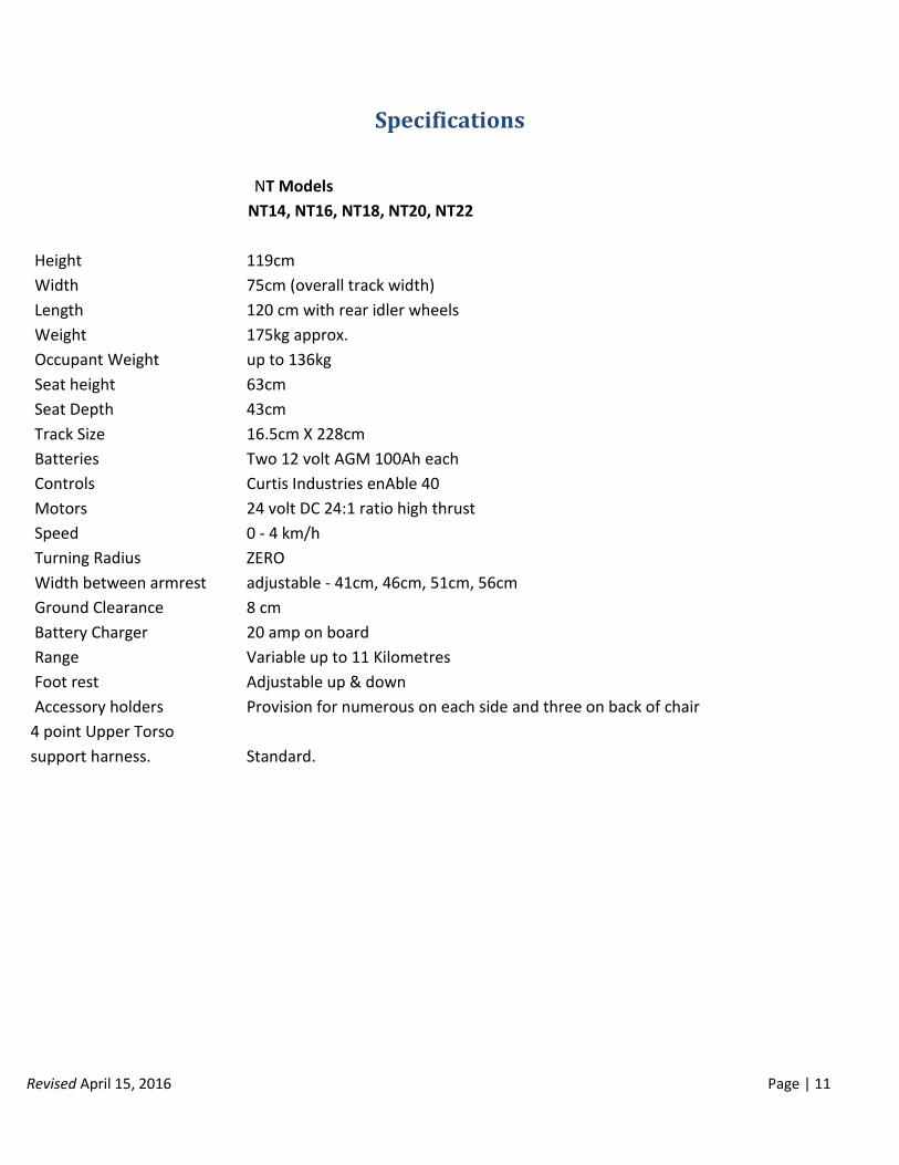
Specifications
Height
Width
Length
Weight
Occupant Weight
Seat height
Seat Depth
Track Size
Batteries
Controls
Motors
Speed
Turning Radius
Width between armrest
Ground Clearance
Battery Charger
Range
Foot rest
Accessory holders
4 point Upper Torso
support harness.
NT Models
NT14, NT16, NT18, NT20, NT22
119cm
75cm (overall track width)
120 cm with rear idler wheels
175kg approx.
up to 136kg
63cm
43cm
16.5cm X 228cm
Two 12 volt AGM 100Ah each
Curtis Industries enAble 40
24 volt DC 24:1 ratio high thrust
0 - 4 km/h
ZERO
adjustable - 41cm, 46cm, 51cm, 56cm
8 cm
20 amp on board
Variable up to 11 Kilometres
Adjustable up & down
Provision for numerous on each side and three on back of chair
Standard.

Revised September 27, 2016 Page | 12

Revised April 15, 2016 Page | 13
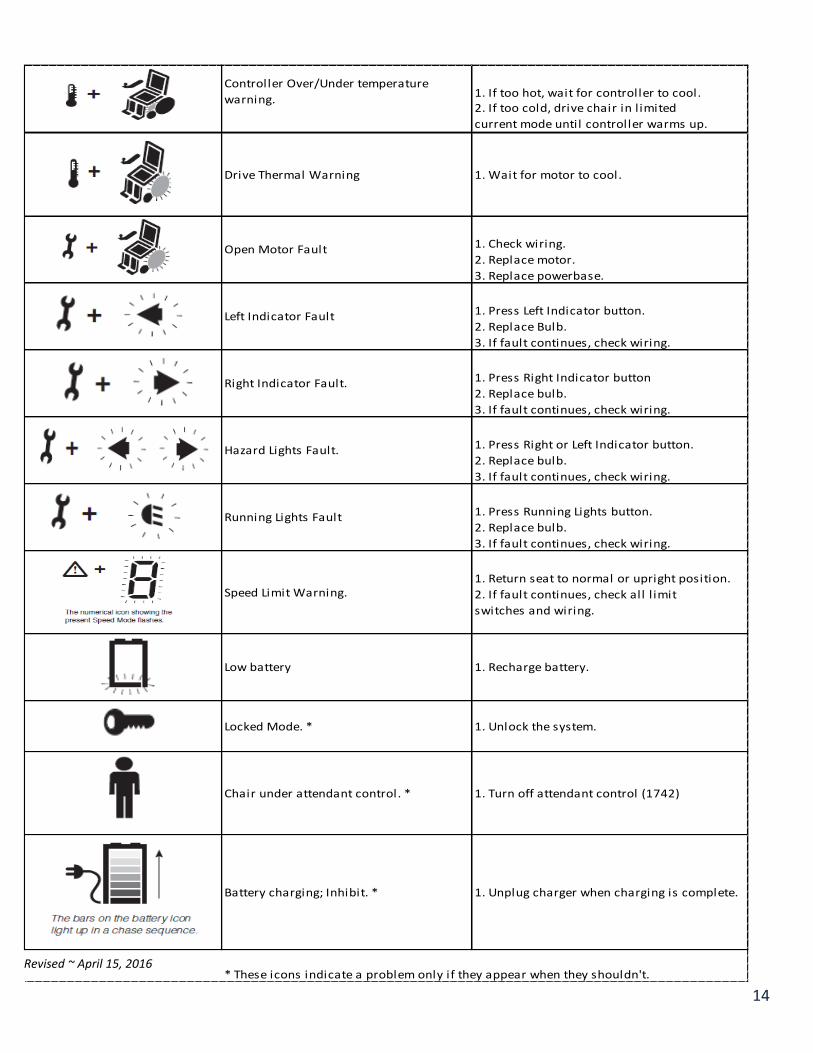
HANDCONTROL LCD DISPLAY FAULT/WARNING REMEDY
Power Section Fault, or Current Sensor
Fault, or EEPROM Fault, or Main Relay
Fault, or Precharge Fault, or HW Failsafe
Fault.
1. Cycle power
2. Replace powerbase.
Handcontrol Fault, or Joystick Fault: 1. Return joystick to neutral and cycle power
Joystick out of center, 2. Recalibrate joystick.
Joystick stuck OOC, 3. Check joystick cable and cable connections.
Joystick Out-of-Range 4. Repalce joystick.
5. Replace hand control.
1. Check cable and cable connections.
2. Replace cable.
1. Check wiring.
2. Replace motor.
3. Replace powerbase.
1. Select drive or a different actuator;
fault may clear.
2. Check wiring.
3. Check that the seatback is not jammed.
4. Check actuator; replace if faulty.
5. Replace powerbase.
1. Select drive or a different actuator;
fault may clear.
2. Check wiring.
3.Check that the seat is not jammed.
4. Check actuator; replace if faulty.
5. Replace powerbase.
1. Select drive or a different actuator;
fault may clear
2. Check wiring.
3. Check that the leg rest is not jammed
4. Check actuator; replace if faulty.
5. Replace powerbase.
1. Recharge battery.
2. Replace old battery.
3. If this is happening frequently,
replace charger.
4. Check charger port on hand control; replace
if damaged.
1. Wait for voltage to come down
2. Replace old battery.
3. Check charger; replace if faulty
Under voltage warning
Overvoltage Warning.
Communications Fault
Brake Fault.
Seatback Actuator Driver Fault
Seat Actuator Driver Fault.
Leg Actuator Driver Fault
Revised ~ April 15, 2016
14
1. If too hot, wait for controller to cool.2. If too cold, drive chair in l imited
current mode until controller warms up.
1. Check wiring.
2. Replace motor.
3. Replace powerbase.
1. Press Left Indicator button.
2. Replace Bulb.
3. If fault continues, check wiring.
1. Press Right Indicator button
2. Replace bulb.
3. If fault continues, check wiring.
1. Press Right or Left Indicator button.
2. Replace bulb.
3. If fault continues, check wiring.
1. Press Running Lights button.
2. Replace bulb.
3. If fault continues, check wiring.
1. Return seat to normal or upright position.
2. If fault continues, check all l imit
switches and wiring.
* These icons indicate a problem only if they appear when they shouldn't.
Chair under attendant control. *
Battery charging; Inhibit. *
1. Wait for motor to cool.
1. Recharge battery.
1. Unlock the system.
1. Turn off attendant control (1742)
1. Unplug charger when charging is complete.
Right Indicator Fault.
Hazard Lights Fault.
Speed Limit Warning.
Running Lights Fault
Low battery
Locked Mode. *
Left Indicator Fault
Controller Over/Under temperature
warning.
Drive Thermal Warning
Open Motor Fault
Revised ~ April 15, 2016
15
Australian Standards Requirements:
The KCF Disability Engineering Action Trackchair has been tested to the following Australian Standards methods: AS3696-1:2008, AS3696-2:2008, AS3696-3:2008, AS3696-4:1992, AS3696-5:1989, AS3696-6:1990, AS3696-8:1998, AS3696-9:2008, AS3696-10:1990, AS3696-14:1998, ISO7176-7:1996 and with the relevant requirements of AS3695.2:2013 (excluding the methods indicated in the report as “not tested” or “not applicable”)
1. This is a Class C wheelchair which is not intended for indoor use but capable of travelling over longer distancesand negotiating outdoor obstacles.
2. Caution should be exercised when negotiating steep slopes as the capabilities of the Action Trackchair mayexceed the capabilities of the operators to safely negotiate these obstacles.
3. The identification plate is attached to the steel seat frame on the left hand side.4. The action of disengaging the drive motor levers will put the Action Trackchair into a freewheel mode and as
such there is no braking on the Action Trackchair.5. Surface temperatures can increase when the Action Trackchair is exposed to external sources of heat (e.g.
sunlight).6. Dispose of used batteries at a registered waste handling facility.7. As of the printing date of this manual the flammability testing of the seating components has not yet been
completed.8. Please refer to page 15 and 16 for information on the power and control system circuitry.9. The Action Trackchair could disturb the operation of other devices in its environment if these devices are
susceptible to electromagnetic interference.10. The driving performance of the Action Trackchair could be influenced by electromagnetic fields that are
generated by other devices.11. The manufacturer, Australian importer, SWL, year of production and serial number are printed on an adhesive
label attached to the steel frame on the right hand side of the seat base.12. An “AS/NZS 3696.19 non-compliant adhesive warning label” is attached to the steel frame stating that the
Action Trackchair is not intended for use as a seat in a motor vehicle.
Revised ~ April 15, 2016
16
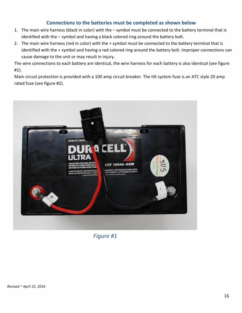
Connections to the batteries must be completed as shown below 1. The main wire harness (black in color) with the – symbol must be connected to the battery terminal that is
identified with the – symbol and having a black colored ring around the battery bolt.
2. The main wire harness (red in color) with the + symbol must be connected to the battery terminal that is
identified with the + symbol and having a red colored ring around the battery bolt. Improper connections can
cause damage to the unit or may result in injury.
The wire connections to each battery are identical, the wire harness for each battery is also identical (see figure
#1).
Main circuit protection is provided with a 100 amp circuit breaker. The tilt system fuse is an ATC style 20 amp
rated fuse (see figure #2).
Figure #1

Revised ~ April 15, 2016
17
Figure #2
To Motor Controller