ACSM1 solar pump inverter (+N5400 and ... - … · List of related manuals You can find manuals and...
68
ABB machinery drives Supplement ACSM1 Solar pump inverter (+N5400 and +N3400)
-
Upload
dangnguyet -
Category
Documents
-
view
216 -
download
3
Transcript of ACSM1 solar pump inverter (+N5400 and ... - … · List of related manuals You can find manuals and...

ABB machinery drives
SupplementACSM1 Solar pump inverter (+N5400 and +N3400)

List of related manuals
You can find manuals and other product documents in PDF format on the Internet. See section Document library on the Internet on the inside of the back cover. For manuals not available in the Document library, contact your local ABB representative.
Drive manuals and guides Code (English)
ACSM1 Speed and Torque Control Program FirmwareManual
3AFE68848261
ACSM1-04 Drive Modules (0.75 to 45 kW) HardwareManual
3AFE68797543

SupplementACSM1
Solar pump inverter (+N5400 and +N3400)
3XXXxxxxxxxxxx Rev xEN
EFFECTIVE: 2013-05-30
Copyright 2015 ABB. All Rights Reserved.
4. Start-up and controls
Table of contents
3AXD50000021292 Rev AEN
EFFECTIVE: 2015-03-31
1. Safety


5
Table of contents
1. Introduction
About this chapter . . . . . . . . . . . . . . . . . . . . . . . . . . . . . . . . . . . . . . . . . . . . . . . . . . . . . . . 9Purpose . . . . . . . . . . . . . . . . . . . . . . . . . . . . . . . . . . . . . . . . . . . . . . . . . . . . . . . . . . . . . . . 9Compatibility . . . . . . . . . . . . . . . . . . . . . . . . . . . . . . . . . . . . . . . . . . . . . . . . . . . . . . . . . . . 9Target audience . . . . . . . . . . . . . . . . . . . . . . . . . . . . . . . . . . . . . . . . . . . . . . . . . . . . . . . . 9Contents . . . . . . . . . . . . . . . . . . . . . . . . . . . . . . . . . . . . . . . . . . . . . . . . . . . . . . . . . . . . . 10Related documents . . . . . . . . . . . . . . . . . . . . . . . . . . . . . . . . . . . . . . . . . . . . . . . . . . . . . 10Terms and abbreviations . . . . . . . . . . . . . . . . . . . . . . . . . . . . . . . . . . . . . . . . . . . . . . . . . 10
2. Safety
About this chapter . . . . . . . . . . . . . . . . . . . . . . . . . . . . . . . . . . . . . . . . . . . . . . . . . . . . . . 13Use of warnings . . . . . . . . . . . . . . . . . . . . . . . . . . . . . . . . . . . . . . . . . . . . . . . . . . . . . . . 13Safety in installation and maintenance . . . . . . . . . . . . . . . . . . . . . . . . . . . . . . . . . . . . . . 14
Electrical safety . . . . . . . . . . . . . . . . . . . . . . . . . . . . . . . . . . . . . . . . . . . . . . . . . . . . . 14Grounding . . . . . . . . . . . . . . . . . . . . . . . . . . . . . . . . . . . . . . . . . . . . . . . . . . . . . . . . . . 15
3. Operating principle and hardware description
About this chapter . . . . . . . . . . . . . . . . . . . . . . . . . . . . . . . . . . . . . . . . . . . . . . . . . . . . . . 17Solar pump inverter overview . . . . . . . . . . . . . . . . . . . . . . . . . . . . . . . . . . . . . . . . . . . . . 17
Control modes . . . . . . . . . . . . . . . . . . . . . . . . . . . . . . . . . . . . . . . . . . . . . . . . . . . . . . 17Control panels . . . . . . . . . . . . . . . . . . . . . . . . . . . . . . . . . . . . . . . . . . . . . . . . . . . . . . 18
MPPT overview . . . . . . . . . . . . . . . . . . . . . . . . . . . . . . . . . . . . . . . . . . . . . . . . . . . . . . . . 18Theory . . . . . . . . . . . . . . . . . . . . . . . . . . . . . . . . . . . . . . . . . . . . . . . . . . . . . . . . . . . . 18Operation . . . . . . . . . . . . . . . . . . . . . . . . . . . . . . . . . . . . . . . . . . . . . . . . . . . . . . . . . . 18I-V characteristics . . . . . . . . . . . . . . . . . . . . . . . . . . . . . . . . . . . . . . . . . . . . . . . . . . . . 19
Dual supply mode . . . . . . . . . . . . . . . . . . . . . . . . . . . . . . . . . . . . . . . . . . . . . . . . . . . . . . 20
4. Quick start-up
About this chapter . . . . . . . . . . . . . . . . . . . . . . . . . . . . . . . . . . . . . . . . . . . . . . . . . . . . . . 21Safety instructions . . . . . . . . . . . . . . . . . . . . . . . . . . . . . . . . . . . . . . . . . . . . . . . . . . . . . . 21Mechanical installation . . . . . . . . . . . . . . . . . . . . . . . . . . . . . . . . . . . . . . . . . . . . . . . . . . 22
Free space requirements . . . . . . . . . . . . . . . . . . . . . . . . . . . . . . . . . . . . . . . . . . . . . . 22Installing power cables . . . . . . . . . . . . . . . . . . . . . . . . . . . . . . . . . . . . . . . . . . . . . . . . . . 23
Connection diagram . . . . . . . . . . . . . . . . . . . . . . . . . . . . . . . . . . . . . . . . . . . . . . . . . . 23Connection procedure . . . . . . . . . . . . . . . . . . . . . . . . . . . . . . . . . . . . . . . . . . . . . . . . 24
Installing control cables . . . . . . . . . . . . . . . . . . . . . . . . . . . . . . . . . . . . . . . . . . . . . . . . . . 25Default I/O connections . . . . . . . . . . . . . . . . . . . . . . . . . . . . . . . . . . . . . . . . . . . . . . . 25 Connection procedure . . . . . . . . . . . . . . . . . . . . . . . . . . . . . . . . . . . . . . . . . . . . . . . . 26
Operating instructions . . . . . . . . . . . . . . . . . . . . . . . . . . . . . . . . . . . . . . . . . . . . . . . . . . . 28
5. Start-up and controls
About this chapter . . . . . . . . . . . . . . . . . . . . . . . . . . . . . . . . . . . . . . . . . . . . . . . . . . . . . . 29Start-up procedure . . . . . . . . . . . . . . . . . . . . . . . . . . . . . . . . . . . . . . . . . . . . . . . . . . . . . 29
Selecting Auto/Manual mode . . . . . . . . . . . . . . . . . . . . . . . . . . . . . . . . . . . . . . . . . . . 29

6
Viewing pump signals . . . . . . . . . . . . . . . . . . . . . . . . . . . . . . . . . . . . . . . . . . . . . . . . 31Editing pump parameters . . . . . . . . . . . . . . . . . . . . . . . . . . . . . . . . . . . . . . . . . . . . . 32
6. Program features
About this chapter . . . . . . . . . . . . . . . . . . . . . . . . . . . . . . . . . . . . . . . . . . . . . . . . . . . . . 35Dry run function . . . . . . . . . . . . . . . . . . . . . . . . . . . . . . . . . . . . . . . . . . . . . . . . . . . . . . . 35
Settings . . . . . . . . . . . . . . . . . . . . . . . . . . . . . . . . . . . . . . . . . . . . . . . . . . . . . . . . . . . 35Diagnostics . . . . . . . . . . . . . . . . . . . . . . . . . . . . . . . . . . . . . . . . . . . . . . . . . . . . . . . . 35
Boost voltage factor . . . . . . . . . . . . . . . . . . . . . . . . . . . . . . . . . . . . . . . . . . . . . . . . . . . . 36Settings . . . . . . . . . . . . . . . . . . . . . . . . . . . . . . . . . . . . . . . . . . . . . . . . . . . . . . . . . . . 36
Voltage limits . . . . . . . . . . . . . . . . . . . . . . . . . . . . . . . . . . . . . . . . . . . . . . . . . . . . . . . . . 37Settings . . . . . . . . . . . . . . . . . . . . . . . . . . . . . . . . . . . . . . . . . . . . . . . . . . . . . . . . . . . 37Diagnostics . . . . . . . . . . . . . . . . . . . . . . . . . . . . . . . . . . . . . . . . . . . . . . . . . . . . . . . . 37
Speed limits . . . . . . . . . . . . . . . . . . . . . . . . . . . . . . . . . . . . . . . . . . . . . . . . . . . . . . . . . . 37Settings . . . . . . . . . . . . . . . . . . . . . . . . . . . . . . . . . . . . . . . . . . . . . . . . . . . . . . . . . . . 37
Flow calculation . . . . . . . . . . . . . . . . . . . . . . . . . . . . . . . . . . . . . . . . . . . . . . . . . . . . . . . 38PQ curve . . . . . . . . . . . . . . . . . . . . . . . . . . . . . . . . . . . . . . . . . . . . . . . . . . . . . . . . . . 38Settings . . . . . . . . . . . . . . . . . . . . . . . . . . . . . . . . . . . . . . . . . . . . . . . . . . . . . . . . . . . 39Diagnostics . . . . . . . . . . . . . . . . . . . . . . . . . . . . . . . . . . . . . . . . . . . . . . . . . . . . . . . . 39
Pump cleaning . . . . . . . . . . . . . . . . . . . . . . . . . . . . . . . . . . . . . . . . . . . . . . . . . . . . . . . . 39Settings . . . . . . . . . . . . . . . . . . . . . . . . . . . . . . . . . . . . . . . . . . . . . . . . . . . . . . . . . . . 40
7. Actual signals and parameters
About this chapter . . . . . . . . . . . . . . . . . . . . . . . . . . . . . . . . . . . . . . . . . . . . . . . . . . . . . 41Actual signals . . . . . . . . . . . . . . . . . . . . . . . . . . . . . . . . . . . . . . . . . . . . . . . . . . . . . . . . . 41
05 SOLAR SIGNALS . . . . . . . . . . . . . . . . . . . . . . . . . . . . . . . . . . . . . . . . . . . . . . . . 41Parameters . . . . . . . . . . . . . . . . . . . . . . . . . . . . . . . . . . . . . . . . . . . . . . . . . . . . . . . . . . 44
10 START/STOP . . . . . . . . . . . . . . . . . . . . . . . . . . . . . . . . . . . . . . . . . . . . . . . . . . . . 4411 START/STOP MODE . . . . . . . . . . . . . . . . . . . . . . . . . . . . . . . . . . . . . . . . . . . . . . 4420 LIMITS . . . . . . . . . . . . . . . . . . . . . . . . . . . . . . . . . . . . . . . . . . . . . . . . . . . . . . . . . 4425 SPEED REF RAMP . . . . . . . . . . . . . . . . . . . . . . . . . . . . . . . . . . . . . . . . . . . . . . . 4434 REFERENCE CTRL . . . . . . . . . . . . . . . . . . . . . . . . . . . . . . . . . . . . . . . . . . . . . . . 4546 FAULT FUNCTIONS . . . . . . . . . . . . . . . . . . . . . . . . . . . . . . . . . . . . . . . . . . . . . . 4547 VOLTAGE CTRL . . . . . . . . . . . . . . . . . . . . . . . . . . . . . . . . . . . . . . . . . . . . . . . . . 4680 PUMP CONTROL . . . . . . . . . . . . . . . . . . . . . . . . . . . . . . . . . . . . . . . . . . . . . . . . 4681 FLOW CALCULATION . . . . . . . . . . . . . . . . . . . . . . . . . . . . . . . . . . . . . . . . . . . . . 5099 START-UP DATA . . . . . . . . . . . . . . . . . . . . . . . . . . . . . . . . . . . . . . . . . . . . . . . . . 51
8. Fault tracing
About this chapter . . . . . . . . . . . . . . . . . . . . . . . . . . . . . . . . . . . . . . . . . . . . . . . . . . . . . 59Safety . . . . . . . . . . . . . . . . . . . . . . . . . . . . . . . . . . . . . . . . . . . . . . . . . . . . . . . . . . . . . . . 59Alarm and fault indications . . . . . . . . . . . . . . . . . . . . . . . . . . . . . . . . . . . . . . . . . . . . . . . 59How to reset . . . . . . . . . . . . . . . . . . . . . . . . . . . . . . . . . . . . . . . . . . . . . . . . . . . . . . . . . . 60Fault history . . . . . . . . . . . . . . . . . . . . . . . . . . . . . . . . . . . . . . . . . . . . . . . . . . . . . . . . . . 60Fault messages . . . . . . . . . . . . . . . . . . . . . . . . . . . . . . . . . . . . . . . . . . . . . . . . . . . . . . . 60Alarm messages . . . . . . . . . . . . . . . . . . . . . . . . . . . . . . . . . . . . . . . . . . . . . . . . . . . . . . 61
9. Technical data
About this chapter . . . . . . . . . . . . . . . . . . . . . . . . . . . . . . . . . . . . . . . . . . . . . . . . . . . . . 63Fuse ratings . . . . . . . . . . . . . . . . . . . . . . . . . . . . . . . . . . . . . . . . . . . . . . . . . . . . . . . . . . 63

7
UL checklist . . . . . . . . . . . . . . . . . . . . . . . . . . . . . . . . . . . . . . . . . . . . . . . . . . . . . . . . . . . 65
Further information
Product and service inquiries . . . . . . . . . . . . . . . . . . . . . . . . . . . . . . . . . . . . . . . . . . . . . 67Product training . . . . . . . . . . . . . . . . . . . . . . . . . . . . . . . . . . . . . . . . . . . . . . . . . . . . . . . . 67Providing feedback on ABB Drives manuals . . . . . . . . . . . . . . . . . . . . . . . . . . . . . . . . . . 67Document library on the Internet . . . . . . . . . . . . . . . . . . . . . . . . . . . . . . . . . . . . . . . . . . . 67

8
Introduction 9
1Introduction
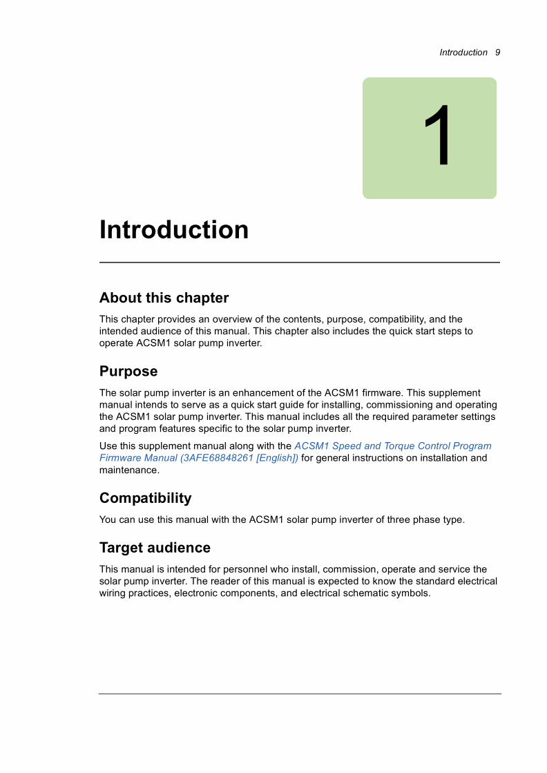
About this chapterThis chapter provides an overview of the contents, purpose, compatibility, and the intended audience of this manual. This chapter also includes the quick start steps to operate ACSM1 solar pump inverter.
PurposeThe solar pump inverter is an enhancement of the ACSM1 firmware. This supplement manual intends to serve as a quick start guide for installing, commissioning and operating the ACSM1 solar pump inverter. This manual includes all the required parameter settings and program features specific to the solar pump inverter.
Use this supplement manual along with the ACSM1 Speed and Torque Control Program Firmware Manual (3AFE68848261 [English]) for general instructions on installation and maintenance.
CompatibilityYou can use this manual with the ACSM1 solar pump inverter of three phase type.
Target audienceThis manual is intended for personnel who install, commission, operate and service the solar pump inverter. The reader of this manual is expected to know the standard electrical wiring practices, electronic components, and electrical schematic symbols.

10 Introduction
ContentsThis manual consists of the following chapters:• Introduction (page 9) provides an overview of this manual.
• Safety (page 13) provides an overview of the safety instruction to follow when using the solar pump inverter.
• Operating principle and hardware description (page 17) includes the overview of the solar pump inverter and its hardware connections.
• Quick start-up (page 21) provides the basic information about mechanical and electrical installation and also includes instructions to quickly operate the solar pump inverter.
• Start-up and controls (page 29) provides an overview of the solar pump inverter and describes the inverter controls to operate the solar pump inverter.
• Program features (page 35) provides an overview of all the solar pump inverter core features such as MPPT function, dual supply mode, dry run function, and so on.
• Actual signals and parameters (page 41) describes the user adjustable settings of the required groups for operating the solar pump inverter.
• Fault tracing (page 59) lists all the alarm and fault messages related to the solar pump inverter and describes the possible cause and corrective actions.
• Technical data (page 63) provides the technical specifications of the solar pump inverter and also the solar status word list.
Related documentsSee List of related manuals on page 2 (inside the front cover).
Terms and abbreviationsThis manual uses the following terms and abbreviations:
Term/Abbreviation Expansion Explanation
AM Asynchronous motor Three-phase AC voltage induction motor with squirrel cage rotor.
B Boolean Data type boolean
Def Default Parameter default value.
E European Refers to types 01E- and 03E- with European parameterization.
EMC filter connected, 50 Hz frequency.
FbEq Fieldbus equivalent The scaling between the value and the integer used in serial communication.
I Integer Data type integer

Introduction 11
MPPT Maximum power point tracking An algorithm to derive maximum power from PV cells.
P Power in kW Power input to determine flow output on the PQ performance curve
Pb Packed boolean Data type packer boolean
PMSM Permanent magnet synchronous motor
Three-phase AC voltage synchronous motor with permanent magnet rotor and sinusoidal back emf voltage.
PV Photovoltaic A device that converts light directly into electricity by the photovoltaic effect.
Q Flow rate in m³/h Flow rate to determine the flow output on the PQ performance curve.
R Real Data type real
S String Data type string
Type Data type Data type
Term/Abbreviation Expansion Explanation

12 Introduction

Safety 13
2
Safety
About this chapter This chapter contains safety instructions which you must follow when installing, operating and servicing the ACSM1 solar pump inverter. If ignored, physical injury or death may follow, or damage may occur to the inverter, motor or driven equipment.
Before installing, commissioning or using the inverter, read the safety instructions chapter in the ACSM1 Speed and Torque Control Program Firmware Manual (3AFE68848261 [English]).
Before changing any default settings of a function, read the warnings and notes for specific software function. For each function, the warnings and notes are given in the subsection describing the related user-adjustable parameters.
Use of warningsWarnings caution you about conditions which can result in serious injury or death and/or damage to the equipment, and advise on how to avoid the danger. The following warning symbols are used in this manual:
Electricity warning warns of hazards from electricity which can cause physical injury and/or damage to the equipment.
General warning warns about conditions, other than those caused by electricity, which can result in physical injury and/or damage to the equipment.

14 Safety
Safety in installation and maintenanceThese warnings are intended for all who work on the inverter, motor cable or motor.
Electrical safety
WARNING! Ignoring the following instructions can cause physical injury or death, or damage to the equipment.
Only qualified electricians are allowed to install and maintain the inverter! • Never work on the photovoltaic generator or inverter and its input/output cables when
the inverter is connected to the power system or to the photovoltaic generator.
• Before working inside the inverter cabinet, switch off or isolate the auxiliary voltage supply to the inverter.
• Isolate the inverter from the photovoltaic generator using the safety switch of the generator or by using the isolation switch.
• Do not touch the input of the isolation switch that has high DC voltage.
• After disconnecting the inverter from the power system or the DC input supply, wait for at least 5 minutes to discharge the intermediate circuit capacitors.
• Measure with a multimeter to ensure that no voltage is present.
• Impedance should be at least 1 MΩ.
• Voltage should be close to 0 V between inverter phases L1, L2, L3 and frame, and between module terminals UDC+ and UDC-.
• Do not make any insulation or voltage withstand tests on the inverter or on the inverter modules.
Note:• The DC connection terminals UDC+ and UDC- carry a dangerous DC voltage of up to
800 V.
• Depending on the external and internal wiring, dangerous voltages of 115 V to 230 V may be present at the different terminals in the auxiliary circuit.
• At the inverter input, the photovoltaic cells generate DC voltage even at low intensity of sunlight.

Safety 15
Grounding
These instructions are intended for all who are responsible for the grounding of the inverter.
WARNING! Ignoring the following instructions can cause physical injury or death, increased electromagnetic interference and equipment malfunction.
• Ground the inverter, motor and adjoining equipment to ensure personnel safety in all circumstances, and to reduce electromagnetic emission and interference.
• Make sure that grounding conductors are adequately sized as required by safety regulations.
• When shielded cables are used, make a 360° high frequency grounding of cable entries at the cabinet lead-through to suppress electromagnetic disturbances. In addition, connect the cable shields to protective earth (PE) to meet safety regulations.
Note:• The power cable shields are suitable for equipment grounding conductors only when
adequately sized to meet safety regulations.
• Standard IEC/EN 62109, 5.2.5 requires that as the normal touch current of the inverter is higher than 3.5 mA AC or 10 mA DC, you must use a fixed protective earth connection.
• A four-conductor system is allowed for input cabling, but shielded symmetrical cable is recommended. To operate as a protective conductor, the shield conductivity must be as follows when the protective conductor is made of the same metal a the phase conductors.
• Automatic disconnection of the supply must be provided in case of discontinuity of the protective earthing conductor.
• A second protective earthing conductor of the same cross-sectional area as the original protective earthing conductor must be provided.
Cross-sectional area of the phase conductors
S (mm2)
Minimum cross-sectional area of the corresponding protective conductor
Sp (mm2)
S
16
S/2
S 16≤
16 S 35≤ ≤
35 S<

16 Safety

Operating principle and hardware description 17
3Operating principle and hardware description
About this chapterThis chapter provides an overview, operation principle and hardware description of the ACSM1 solar pump inverter.
Solar pump inverter overviewThe ACSM1 solar pump inverter is a low voltage AC drive of 0.3 to 355 KW rating designed to operate with energy drawn from photovoltaic cells (PV). The inverter is customized to operate in dual supply mode, so the grid connected supply is used in the absence of energy from PV cells. The inverter functions with the latest in technology maximum power point tracking (MPPT) algorithm to derive maximum power from the PV cells at any instant.
The inverter is specifically designed to meet the requirements of pump manufacturers and the original equipment manufacturers (OEM). For more details of the solar pump inverter features, see section Program features, page 35.
Control modes
The solar pump inverter operates in local control mode and in remote control mode identical to the ordinary ACSM1 drive. • Local control—interfaces through the panel.
• Remote control—interfaces through external control signal. For the external control through digital input, refer the Default I/O connections, page 25.

18 Operating principle and hardware description
To switch between local and remote control modes use the LOC/REM key on the control panel. For more information, see section How to start, stop and switch between local and remote control in ACSM1 Speed and Torque Control Program Firmware Manual (3AFE68848261 [English]).
Note: Ensure that the inverter is in local control before starting or stopping the inverter using the control panel.
Control panels
The solar pump inverter works with either of the two different control panel types:• Basic control panel—provides basic tools for manual entry of parameter values.
• Assistant control panel—includes pre-programmed assistants to automate the most common parameter setups and provides language support.
See Start-up procedure section for information on Viewing or Editing parameter values using control panel.
MPPT overview
Theory
The solar pump inverter uses the maximum power point tracking (MPPT) control program to improve the efficiency of solar energy systems. The output of the photovoltaic (PV) cell is proportional to its area and intensity, while the output voltage is limited by p-n junction from 0.6 to 0.7 V. Therefore when the output voltage is constant, output power is proportional to intensity and surface area. The current and voltage at which the PV cell generates maximum power is known as the maximum power point.
Operation
The MPPT controller follows different strategies to derive the maximum power from the PV array. The internal MPPT algorithm is used to derive maximum power from the PV cell at any instant. This is achieved by modifying the operating voltage or current in the PV cell until the maximum power is obtained.
When the output voltage is zero, the PV cells create short circuit current. If the PV cells are not connected to any load, the output voltage is equal to the open circuit voltage. The maximum power point is obtained at the knee of the I-V curve. See the I-V characteristics shown below.

Operating principle and hardware description 19
I-V characteristics
The I-V curve is not constant since intensity and temperature changes during day time. Under constant temperature, current changes linearly with intensity and voltage changes logarithmically with intensity. Since the voltage variation is small with respect to intensity changes, maximum power varies proportionally with intensity.
8
6
4
2
10
200 400 600 800Vpvn
0
IactnPkwn

20 Operating principle and hardware description
Dual supply modeThe solar pump inverter operates in dual supply mode either with a three phase input supply from the grid or with DC input supply from PV cells. A four-pole changeover switch enables switching between the two supply modes. At a given time only one supply (PV cell or grid) will be connected to the drive.
Note: Use two poles of the changeover switch in series to ensure that the voltage applied across each pole is half of the full DC voltage.
PV cell
4-pole change over switch
Solar pump inverter
PV cell
Grid supplyMotor and
Pump
To inverter UDC+ and UDC-
To inverter U1, V1, W1
G id l

Quick start-up 21
4Quick start-up
About this chapterThis chapter includes the basic information about the mechanical and electrical installation of solar pump inverter and also provides steps to quickly operate the inverter.
For general instructions on installation and maintenance of ACSM1 Drives, see ACSM1 Speed and Torque Control Program Firmware Manual (3AFE68848261 [English]).
Safety instructions
WARNING! All electrical installation and maintenance work on the inverter must be carried out by qualified electricians only. Follow the safety instructions listed below.
• Never work on the inverter, the braking chopper circuit, the motor cable or the motor when input power is applied to the inverter.
• After disconnecting the input power, always wait for 5 minutes to let the intermediate circuit capacitors discharge. Always ensure by measuring that no voltage is actually present.
• A rotating permanent magnet motor generates a dangerous voltage. Always ensure to lock the motor shaft mechanically before connecting a permanent magnet motor to the inverter, and before doing any work on an inverter system connected to a permanent magnet motor.
22 Quick start-up
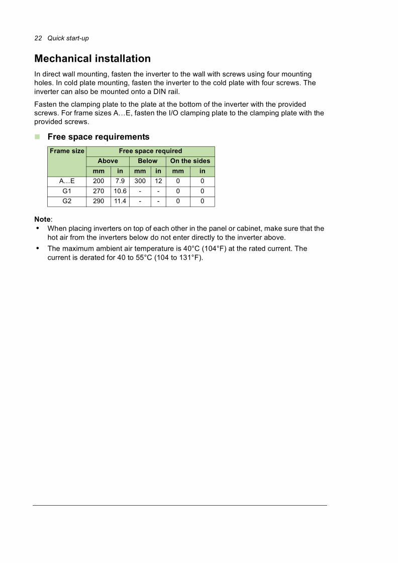
Mechanical installationIn direct wall mounting, fasten the inverter to the wall with screws using four mounting holes. In cold plate mounting, fasten the inverter to the cold plate with four screws. The inverter can also be mounted onto a DIN rail.
Fasten the clamping plate to the plate at the bottom of the inverter with the provided screws. For frame sizes A…E, fasten the I/O clamping plate to the clamping plate with the provided screws.
Free space requirements
Note:• When placing inverters on top of each other in the panel or cabinet, make sure that the
hot air from the inverters below do not enter directly to the inverter above.
• The maximum ambient air temperature is 40°C (104°F) at the rated current. The current is derated for 40 to 55°C (104 to 131°F).
Frame size Free space required
Above Below On the sides
mm in mm in mm in
A…E 200 7.9 300 12 0 0
G1 270 10.6 - - 0 0
G2 290 11.4 - - 0 0

Quick start-up 23
Installing power cables
Connection diagram
Note:• Do not use an asymmetrically constructed motor cable.
• Route the motor cable, input power cable and control cables separately.
• Make sure that the maximum cable lengths are not exceeded.
U2 V2 W2
Motor3 ~
V1U1 W1
PE
R - R+
Optional brake resistor or
Common DC
UDC + UDC -U1 V1 W1
L1 L2 L3
PE
(PE) (PE)
ACSM1-04
1) 2)
3)
PV cell
+ -
24 Quick start-up
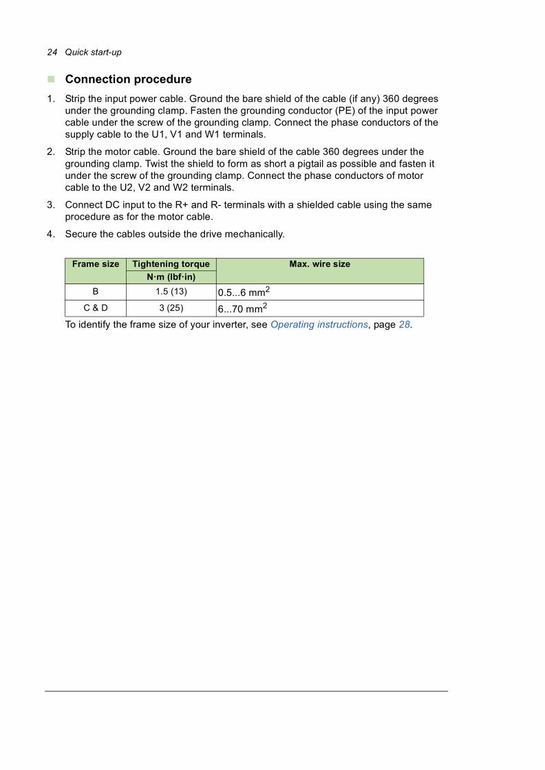
Connection procedure
1. Strip the input power cable. Ground the bare shield of the cable (if any) 360 degrees under the grounding clamp. Fasten the grounding conductor (PE) of the input power cable under the screw of the grounding clamp. Connect the phase conductors of the supply cable to the U1, V1 and W1 terminals.
2. Strip the motor cable. Ground the bare shield of the cable 360 degrees under the grounding clamp. Twist the shield to form as short a pigtail as possible and fasten it under the screw of the grounding clamp. Connect the phase conductors of motor cable to the U2, V2 and W2 terminals.
3. Connect DC input to the R+ and R- terminals with a shielded cable using the same procedure as for the motor cable.
4. Secure the cables outside the drive mechanically.
To identify the frame size of your inverter, see Operating instructions, page 28.
Frame size Tightening torque Max. wire size
N·m (lbf·in)
B 1.5 (13) 0.5...6 mm2
C & D 3 (25) 6...70 mm2

Quick start-up 25
Installing control cables
Default I/O connections
X1
1 +24VI External power input
2 GND 24 V DC, 1.6 A
X2
1 NO Relay output
250 V AC / 30 V DC
2A
2 COM
3 NC
X3
1 +24VD +24V DC*
2 DGND Digital I/O ground
3 DI1 Digital input 1
4 DI2 Digital input 2
5 +24VD +24V DC*
6 DGND Digital I/O ground
7 DI3 Digital input 3
8 DI4 Digital input 4
9 +24VD +24V DC*
10 DGND Digital I/O ground
11 DI5 Digital input 5
12 DI6 Digital input 6
13 +24VD +24V DC*
14 DGND Digital I/O ground
15 DIO1 Digital input/output 1
16 DIO2 Digital input/output 2
17 +24VD +24V DC*
18 DGND Digital I/O ground
19 DIO3 Digital input/output 3
X4
1 +VREF Reference voltage (+)
2 -VREF Reference voltage (-)
3 AGND Ground
4 AI1+ Analogue input 1 (Current or voltage, selectable by jumper J1)
5 AI1-
6 AI2+ Analogue input 2 (Current or voltage, selectableby jumper J2)
7 AI2-
J1 AI1 current/voltage selection
J2 AI2 current/voltage selection
8 TH Thermistor input
9 AGND Ground
10 AO1 (I) Analogue output 1 (current)
11 AO2 (U) Analogue output 2 (voltage)
12 AGND Ground
X5
J3 Drive-to-drive link termination
1 B
Drive-to-drive link. See separate section below.2 A
3 BGND
X6
1 OUT1
Safe Torque Off. Both circuits must be closed for
the drive to start. See separate section below.
2 OUT2
3 IN1
4 IN2

26 Quick start-up
Connection procedure
1. Ground all the control cables connected to the JCU control unit at the control cable clamp plate.
2. Fasten the clamp plate (1) using four screws with a tightening torque of 0.7 Nm (6.2
lbf·in).

Quick start-up 27
3. Remove outer insulation of the cable at the cable clamp and ground the bare shield under the clamp (2). Use a tightening torque of 1.5 Nm (13 lbf·in).
4. Use shrink tubing or insulation tape (3) to contain any stray strands at the terminal block.
5. If you are using multiple shields, terminate the shield with a lug and fasten with a screw at the clamp plate and leave the other end of the shield unconnected or ground it indirectly through a few nanofarads high frequency capacitor, for example 3.3 nf/630 V.
6. If the shields are in the same ground line with no significant voltage drop between the end points, shields can be grounded directly at the both ends.
7. Keep any signal wire pairs twisted as close to the terminals as possible.Twisting the wire with its return wire reduces disturbances caused by inductive coupling.

28 Quick start-up
Operating instructionsThe solar pump inverter is developed using the ACSM1 firmware. Install the inverter as defined in sections Mechanical installation, Installing power cables, and Installing control cables. Before operating the inverter, set the required parameters defined in the following steps.
If the inverter power rating matches the motor power rating, the inverter is ready to run. If any parameter tuning such as acceleration and deceleration times, maximum and minimum speeds, and so on is required, ACSM1 Speed and Torque Control Program Firmware Manual (3AFE68848261 [English]).
Step Action Additional information
1 Install the solar pump inverter. See ACSM1-04 Drive Hardware Manual in List of related manuals.
2 Connect the AC/DC input and motor cables and the control cables.
See ACSM1-04 Drive Hardware Manual in List of related manuals.
3 Enter the commissioning data parameters. See parameter group 99 START-UP DATA.
4 Set the basic application data using either the control panel or the Drive window light PC tool application:
Group 10 START/STOP
Group 11 START/STOP MODE
Group 20 LIMITS
Group 80 PUMP CONTROL
Group 81 FLOW CALCULATION
Group 99 START-UP DATA
See ACSM1 Firmware Manual in List of related manuals.
The inverter is supported by version 2.91 or later of the Drive studio 2 PC tool.
5 Monitor the inverter signals. See ACSM1 Firmware Manual in List of related manuals.

Start-up and controls 29
5Start-up and controls
About this chapterThis chapter describes the start-up operation of the solar pump inverter.
Start-up procedureThe start-up procedure to set up the solar pump inverter is similar to the ordinary ACSM1 drive. See section Starting up the drive in ACSM1 Speed and Torque Control Program Firmware Manual (3AFE68848261 [English]).
Selecting Auto/Manual mode
• In auto mode, the inverter does not need any manual start/stop input.The inverter starts modulating if the current DC bus voltage is more than the start DC voltage set in parameter 80.03 START DC VOLT. To use the auto mode, set the parameter 80.01 AUTO/MANUAL SEL to AUTO [0].
• In manual mode, the drive starts by external connections to either of the digital inputs common DI1, DI2 or DI3 pins as shown in Default I/O connections. The inverter waits for the activation of digital inputs defined in parameter 80.02 MANUAL START CMD. To use the manual mode, set the parameter 80.01 AUTO/MANUAL SEL to MANUAL [1].
Note: Only one input can be selected at a time.

30 Start-up and controls
To select auto/manual mode in the control panel, follow these steps:
Step Description Keys Control panel
1 Press MENU to go to the main menu.
2 Select PARAMETERS with the UP/DOWN keys and press ENTER.
3 Select parameter group 80 PUMP CONTROL with the UP/DOWN keys and press SEL.
4 Select the parameter 80.01 AUTO/MANUAL SEL with the UP/DOWN keys. Press EDIT to change the parameter value.
5 Press the UP/DOWN keys to change the parameter value.
For more details, see parameter 80.01 AUTO/MANUAL SEL.
Note: MANUAL is the default selection.

Start-up and controls 31
Viewing pump signals
The parameters 05.01...05.08 display the actual signals of the pump. These values are read only. To view these values in the control panel, follow these steps:
6 Press SAVE to store the modified value or press CANCEL to leave the set mode. Any modifications not saved are cancelled.
7 Press EXIT to return to the main menu.
Step Description Keys Control panel
1 Select parameter group 05 SOLAR SIGNALS with the UP/DOWN keys and press SEL.
2 Press the UP/DOWN keys to view the actual values displayed below individual parameters.
For more details, see section Actual signals, page 41.
Press EXIT to return to the main menu.
Step Description Keys Control panel

32 Start-up and controls
Editing pump parameters
The parameters 80.01...80.26 are user adjustable parameters to control the pump operation. The below steps explain the editing of inverter start voltage and inverter reset time. Similarly, edit the other pump parameters in this group.
Step Description Keys Control panel
Setting inverter starting voltage
1 Select parameter group 80 PUMP CONTROL with the UP/DOWN keys and press SEL.
2 Select parameter 80.03 START DC VOLT with the UP/DOWN keys. Press EDIT to change the parameter value.
You can edit the minimum DC voltage to start the inverter.
Note: If you change this value while the inverter is running, the changed value is effective only during the next start.
3 Press the UP/DOWN keys to change the parameter value and press SAVE to store the modified value or press CANCEL to leave the set mode. Any modifications not saved are cancelled.
Press EXIT to return to the listing of parameter groups, and again to return to the main menu.

Start-up and controls 33
Setting inverter reset time
1 Select parameter 80.19 FAULT RESET TIME with the UP/DOWN keys. Press EDIT to change the parameter value.
You can set the auto reset time to start the inverter after it has tripped in the event of under-voltage fault, PV cell maximum voltage fault or when actual speed decreases below the minimum motor speed limit.
2 Press the UP/DOWN keys to change the parameter value.
Press SAVE to store the modified value or press CANCEL to leave the set mode. Any modifications not saved are canceled.
Step Description Keys Control panel

34 Start-up and controls

Program features 35
6Program features
About this chapterThis chapter describes the pump control features of solar pump inverter. Each feature includes a list of related user settings, actual signals, and/or fault and alarm messages.
Dry run functionThe solar pump inverter trips to a DRY RUN when the water flow is not available at the pump inlet or when a blockage occurs in the pump. During these conditions the inverter consumes less current than the minimum load current (80.16 MIN LOAD CURRENT) or the actual motor current is lower than the minimum load current for the defined trip time.
Note: The dry run function is disabled during the initial start up time.
Settings
Diagnostics
Parameter Additional information
80.17 DRY RUN TRP TIME Dry run trip time
80.18 DRY RUN RST TIME Auto reset time in case of a dry run fault.
Fault Additional information
DRY RUN Fault message to notify that pump is dry.

36 Program features
Boost voltage factorBoost voltage factor enables increasing the pump speed. When the actual DC bus voltage is greater than the boost voltage (80.08 BOOST VOLT), the pump speed increases by a defined boost factor (80.09 BOOST FACTOR). When the DC voltage reaches a set voltage as per V/f ratio, the output frequency is increased. The voltage is controlled to be substantially at the limit value by changing the output frequency of the inverter. The MPPT algorithm achieves this increased speed limit only if the actual DC bus voltage is appropriate to the boost factor.
Settings
Parameter Additional information
80.08 BOOST VOLT DC voltage reference to activate boost factor.
80.09 BOOST FACTOR Factor at which the inverter functions the best.

Program features 37
Voltage limitsThe solar pump inverter operates within the voltage limits defined for PV cells. If the DC voltage limit is above 80.05 PV CELL MAX VOLT, the inverter trips to a PV maximum fault. If the DC voltage limit is below 80.04 PV CELL MIN VOLT, the inverter stops modulating.
Settings
Diagnostics
Speed limits The ACSM1 solar pump inverter operates within the defined speed limits set in the group 80 PUMP CONTROL, see page 46 parameters. • Minimum pump speed—Below this value, inverter generates alarm and stops the
pump operation. The inverter restarts automatically only after the 80.19 FAULT RESET TIME. This operation of the inverter prevents the pump from running at a low speed (where the pump capacity drops and is near zero).
• Maximum pump speed—The pump operates within this speed limit defined by MPPT in 80.07 PUMP MAXIMUM SPD, provided that the maximum speed limit of the inverter in 20.01 MAXIMUM SPEED is equal to or higher than this value.
Note: Ensure that the pump speed is always defined within the allowed speed limit of the inverter.
Settings
Parameter Additional information
80.04 PV CELL MIN VOLT Minimum DC voltage below which the inverter cannot operate.
80.05 PV CELL MAX VOLT Maximum DC voltage.
Fault Additional information
PV MAX VOLT Fault message to notify that DC bus voltage in the inverter is higher than the maximum DC voltage (80.05 PV CELL MAX VOLT).
Parameter Additional information
80.06 PUMP MINIMUM SPD Minimum motor speed allowed.
80.07 PUMP MAXIMUM SPD Maximum motor speed allowed.
20.01 MAXIMUM SPEED Maximum speed limit.

38 Program features
Flow calculationThe flow calculation function provides a reasonably accurate calculation of the flow without the installation of a separate flow meter. The function defines the flow estimate using the pump performance curve and drive actual load. The PQ (power/flow) performance curve enables calculating the flow output from the pump. The performance curve is provided by the pump manufacturer. The user saves five operating points (P,Q) of the performance curve to drive parameters.
PQ curve
The solar pump inverter records and stores the flow rate on each day and provides the required data for current day and current year.
Note: • The flow calculations are available only with assistant control panel. Ensure that the
assistant control panel is attached before starting the inverter.
• Do not use the flow calculation function outside the normal operating range of the pump.
• Do not use the flow calculation function for invoicing purposes.
• Ensure that power and flow points are in incremental order with non-zero values.
81.05
81.01
81.11
P[kW]
1
2
34
5
Q[m3/h]81.15

Program features 39
Settings
Diagnostics
Pump cleaning The solar pump inverter provides the pump cleaning function to prevent solids from building up on pump impellers or piping. The function consists of a programmable sequence of forward and reverse runs of the pump to shake off any residue on the impeller or piping.
The cleaning sequence can be activated only in the manual mode of operation. The cleaning sequence starts in the forward direction and follows the reverse direction. This cycle repeats three times. If any intermediate fault occurs, the pump cleaning function stops.
Parameter Additional information
81.01 PQ CURVE P1...81.05 PQ CURVE P5 Input power of pump at points 1...5 on the PQ performance curve.
81.11 PQ CURVE Q1...81.15 PQ CURVE Q5 Flow rate at points 1...5 on the PQ curve respectively.
81.21 PUMP EFFICIENCY Efficiency of the pump.
Actual signal Additional information
05.06 CALCULATED FLOW Calculated flow rate in cubic meter per hour.
05.07 TODAY FLOW Measured flow for the current day in cubic meter.
05.08 CUMULA YEAR FLOW Measured flow for current year in cubic meter.
Fo
rwa
rdR
eve
rse
Pump cleantime
De
lay
time
P 2
5.0
3
P 2
5.0
4
Pump clean speed
Pump clean speed
Time

40 Program features
Settings
Parameter Additional information
80.21 PMP CLEAN SELECT Initiates pump cleaning sequence.
80.22 PMP CLEAN SPEED Speed at which the pump cleaning sequence is initiated.
80.23 PMP CLEAN TIME Pump cleaning time.

Actual signals and parameters 41
7Actual signals and parameters
About this chapterThis chapter describes the actual signals and user-adjustable parameters of the MPPT function specific to the solar pump inverter. Refer these parameters in addition to the actual signals and parameters described in the ACSM1 Speed and Torque Control Program Firmware Manual (3AFE68848261 [English]).
Actual signals
Actual signals
No. Name/Value Description FbEq
05
05 SOLAR SIGNALS Basic signals for monitoring the solar pump inverter (read-only). The inverter sets the values based on measurements or calculations.
05.01 SOLAR STS WORD1 Solar status word 1. 1 = 1 h
0...65535
Bit 00 Drive ready
Bit 01 Enabled
Bit 02 Running
Bit 03 Fault
Bit 04 Dry run
Bit 05 Over volt
Bit 06 Under volt
Bit 07 Low speed

42 Actual signals and parameters
Bit 08 Short circuit
Bit 09 Earth fault
Bit 10 Motor phase loss
Bit 11 Supply phase loss
Bit 12 Stall fault
Bit 13 Over current
Bit 14 External fault
Bit 15 Start delay active
05.02 SOLAR STS WORD2 Solar status word 2. 1 = 1 h
0...65535
Bit 00 PS Communication
Bit 01 AI Supervision
Bit 02 DC Not charged
Bit 03 Local ctrl loss
Bit 04 Drive over temp
Bit 05 ID Run fail
Bit 06 Output wiring fault
Bit 07 Safe torque off
Bit 08 Motor over temp
Bit 09 Start enable
Bit 10 Run enable
Bit 11 APPL Loading
Bit 12...Bit 15 Reserved
05.03 PUMP RUN HOUR Shows the measured flow of current day in cubic meter.
Note: You can reset this value using parameter 80.26 RESET RUN TIME.
1 = 1 h
0...2147483647 h Pump run hour.
Actual signals
No. Name/Value Description FbEq

Actual signals and parameters 43
05.06 CALCULATED FLOW Shows the measured flow of current year in cubic decameter. The value displayed is the
measured flow from first day to current day of the year.
Note: You can reset this value using parameter 81.31 RESET FLOW.
100 = 1 m³/h
0...32767.00 m³/h Calculated flow.
05.07 TODAY FLOW Shows the measured flow of current day in cubic meter.
Note: You can reset this value using parameter 81.31 RESET FLOW.
1 = 1 m3
0...2147483647 m³ Today flow.
05.08 CUMULA YEAR FLOW Shows the measured flow of current year in cubic meter. The value displayed is the measured flow from first day to current day of the year.
Note: You can reset this value using parameter 81.31 RESET FLOW.
1 = 1 m3
0...2147483647 m³ Cumula year flow.
Actual signals
No. Name/Value Description FbEq

44 Actual signals and parameters
Parameters
All parameters
No. Name/Value
Description Def/ FbEq
10
10 START/STOP Defines the sources for external start, stop and direction control.
10.70 FAULT RESET SEL
Selects the source for the external fault reset signal. The signal resets the drive after a fault trip if the cause of the fault no longer exists. 1 = Fault reset.
10.71 EM OFF3 Selects the source for the emergency stop OFF3.
0 = OFF3
Active: The drive is stopped along the emergency stop ramp time.
Note: This parameter cannot be changed while the drive is running.
C.True
11
11 START/STOP MODE
Selects start and stop functions as well as the autophasing mode, define the DC magnetising time of the motor, and configure the DC hold function.
11.70 STOP MODE Selects the motor stop function. COAST(1)
1...2 Stop mode. 1 = 1
COAST Stop by cutting of the motor power supply. The motor coasts to a stop.
WARNING! If the mechanical brake is used, ensure it is safe to stop the drive by coasting.
RAMP Stop along ramp. See parameter group 25 SPEED REF RAMP.
20
20 LIMITS Defines inverter operation limits.
Note: Speed values are used in vector control and frequency values are used in scalar control.
20.01 MAXIMUM SPEED Defines the allowed maximum speed limit. 3000 rpm
0...30000 rpm Allowed maximum speed. 1 = 1 rpm
20.02 MINIMUM SPEED Defines the allowed minimum speed. -3000 rpm
-30000...0 rpm Allowed minimum speed.
25 SPEED REF RAMP
Speed reference ramp setting.
Note: Emergency stop OFF1 uses the currently active ramp time.
25.02 SPEED SCALING Defines the speed value used in acceleration and deceleration.
3000

Actual signals and parameters 45
0...30000 rpm Speed value for acceleration/deceleration.
25.03 ACC TIME Defines the acceleration time, that is, the time required for the speed to change from zero to the speed value defined by parameter 25.02 SPEED SCALING.
20
0...1800 s Acceleration time.
25.04 DEC TIME Defines the deceleration time, that is, the time required for the speed to change from the speed value defined by parameter 25.02 SPEED SCALING to zero.
20
0...1800 s Deceleration time.
34
34 REFERENCE CTRL
Defines the reference source and type selection.
34.01 EXT1/EXT2 SEL Selects the source for external control location EXT1/EXT2 selection. 0 = EXT1. 1 = EXT2.
C.FALSE
46
46 FAULT FUNCTIONS
Defines the drive behavior upon a fault situation.
46.11 STALL FREQUENCY
Stall frequency limit. See parameter 46.09 STALL FUNCTION in ACSM1 Speed and Torque Control Program Firmware Manual (3AFE68848261 [English]).
Note: Setting the limit below 10 Hz is not recommended.
10 Hz
0.5...1000 Hz Stall frequency limit.
46.12 STALL TIME Stall time. See parameter 46.09 STALL FUNCTION in ACSM1 Speed and Torque Control Program Firmware Manual (3AFE68848261 [English]).
10 sec
0...3600 sec Stall time.
47
All parameters
No. Name/Value
Description Def/ FbEq

46 Actual signals and parameters
47 VOLTAGE CTRL Defines settings for overvoltage and undervoltage control, and supply voltage.
47.01 OVERVOLTAGE CTRL
Enables the overvoltage control of the intermediate DC link. Fast braking of a high inertia load causes the voltage to rise to the overvoltage control limit. To prevent the DC voltage from exceeding the limit, the overvoltage controller automatically decreases the braking torque.
Note: If a braking chopper and resistor or a regenerative supply section are included in the drive, the controller must be disabled.
DISABLE
Disable Overvoltage control disabled.
Enable Overvoltage control enabled.
47.05 LOW VOLT MOD ENA
Enables/disables (or selects a signal source that enables/disables) Low voltage mode.
0 = Low voltage mode disabled,
1 = Low voltage mode enabled.
C.TRUE
80
80 PUMP CONTROL Defines pump control parameters.
80.01 AUTO/MANUAL SEL
Selects the start mode of the inverter. 1 = 1
AUTO Inverter starts automatically if DC bus voltage is more than the parameter 80.03 START DC VOLT.
0
MANUAL Inverter starts when the manual start command is on. See parameter 80.02 MANUAL START CMD.
1
80.02 MANUAL START CMD
Defines the source for inverter to start in manual mode. The selection is effective when parameter 80.01 MANUAL is MANUAL and the inverter is in remote control mode.
1 = 1
0...4 Manual start command. DI1
DI1 Start and stop through digital input DI1.
0 = Stop, 1 = Start
0
DI2 Start and stop through digital input DI2.
0 = Stop, 1 = Start
1
DI3 Start and stop through digital input DI3.
0 = Stop, 1 = Start
2
All parameters
No. Name/Value
Description Def/ FbEq

Actual signals and parameters 47
DI1P, 2P Pulse starts through digital input DI1.
0 -> 1: Start.
Pulse stops through digital input DI2. 1 -> 0: Stop
Note: To start the inverter, activate DI2 prior to feeding pulse to DI1.
3
COMM_WORD Start and stop control from the parameter 10.12 FBA MAIN CW, see ACSM1 Speed and Torque Control Program Firmware Manual (3AFE68848261 [English]).
4
80.03 START DC VOLT Defines the minimum DC voltage to start the inverter.
Note: If you change this value while the inverter is running, the changed value is effective only during the next start.
10 = 1 V
225.0...800.0 V DC voltage. 225.0
80.04 PV CELL MIN VOLT
Defines the minimum DC voltage below which the inverter cannot operate.
Note: The inverter stops operating below this voltage.
10 = 1 V
225.0...800.0 V DC voltage. 225.0
80.05 PV CELL MAX VOLT
Defines the maximum DC voltage. At any value above this voltage, the inverter trips due to PV MAX VOLT fault.
10 = 1 V
225.0...800.0 V DC voltage. 640.0
80.06 PUMP MINIMUM SPD
Defines the minimum motor speed. At any value below this speed, the inverter stops functioning and auto restarts after the time defined in parameter 80.19 FAULT RESET TIME. This setting avoids unnecessary operation of pump at low speed.
1 = 1 rpm
0...30000 rpm Speed 0
80.07 PUMP MAXIMUM SPD
Defines the maximum motor speed. 1 = 1 rpm
0...30000 rpm Speed 3000
80.08 BOOST VOLT Defines the DC voltage above which the parameter 80.09 BOOST FACTOR is effective. Below this value, motor speed follows the V/F factor.
10 = 1 V
250.0...600.0 V DC voltage. 450.0
All parameters
No. Name/Value
Description Def/ FbEq

48 Actual signals and parameters
80.09 BOOST FACTOR Defines the factor at which the inverter functions the best. This parameter is effective when DC voltage is above the value in parameter 80.08 BOOST VOLT.
100 = 1
0.75...1.25 Boost factor 1.00
80.15 DRY RUN SEL DI Selects the input for dry run protection. 1 = 1
1...11 Dry run selection. With_P80.16
DI1 Digital input DI1. Defines the digital input DI1 as the control for dry run protection.
1
DI2 See selection DI1. 2
DI3 See selection DI1. 3
DI4 See selection DI1. 4
DI5 See selection DI1. 5
DI1(INV) Inverted digital input DI1. Defines the inverted digital input DI1 as the control for dry run protection.
6
DI2(INV) See selection DI1(INV). 7
DI3(INV) See selection DI1(INV). 8
DI4(INV) See selection DI1(INV). 9
DI5(INV) See selection DI1(INV). 10
WITH_P80.16 See parameter 80.16 MIN LOAD CURRENT 11
80.16 MIN LOAD CURRENT
Defines the minimum load current for dry run protection of inverter. When actual motor current is less than this value for the time defined in parameter 80.17 DRY RUN TRP TIME, the inverter trips due to DRY RUN.
10 = 1 A
0...150 A Current 0
80.17 DRY RUN TRP TIME
Allows inverter to wait for this time to trip if pump is in dry run condition. See parameter 80.16 MIN LOAD CURRENT.
1 = 1 min
0...5 mins Time 2 mins
80.18 DRY RUN RST TIME
Allows inverter to wait for this time to reset in case of a dry run fault. After this reset time, inverter starts automatically.
1 = 1 min
2...300 mins Time 2 mins
All parameters
No. Name/Value
Description Def/ FbEq

Actual signals and parameters 49
80.19 FAULT RESET TIME
Allows inverter to wait for this time to restart automatically in case inverter tripped due to under-voltage fault, PV cell maximum voltage fault or when actual speed decreased below the minimum motor speed defined in parameter 80.06 PUMP MINIMUM SPD.
1 = 1 min
2...20 mins Time 2 mins
80.21 PMP CLEAN SELECT
Enables the pump cleaning sequence for the inverter in the manual mode (see parameter 80.01 AUTO/MANUAL SEL) and defines the selection conditions.
WARNING! Before enabling the pump cleaning sequence, make sure that it can be performed safely with the connected
equipment.
Note: When the pump cleaning sequence is active, it cannot be stopped with OFF selection. After the cleaning sequence is completed successfully or if the sequence is interrupted due to a fault, it automatically switches to OFF selection.
1 = 1
0...1 Pump cleaning sequence. OFF
OFF Disables pump cleaning sequence. 0
ON Enables pump cleaning sequence. 1
80.22 PMP CLEAN SPEED
Defines the speed at which the pump cleaning sequence is initiated.
1 = 1 rpm
500...30000 rpm Speed. 500 rpm
80.23 PMP CLEAN TIME Defines the pump cleaning time for which the motor rotates in one direction (forward or reverse) within which the cleaning sequences are counted.
1 = 1 sec
1...300 sec Time 60 sec
80.26 RESET RUN TIME Allows to reset the pump. See parameter 05.03 PUMP RUN HOUR.
1 = 1
0...1 Reset run time. DONE
DONE Run hour reset is done. 0
RESET Activates the pump run hour reset. 1
81
All parameters
No. Name/Value
Description Def/ FbEq

50 Actual signals and parameters
81 FLOW CALCULATION
Defines flow calculation parameters.
81.01 PQ CURVE P1 Defines the input power of pump in kW at point 1 on the PQ performance curve.
For description of PQ curve, see section Flow calculation, page 38.
10 = 1 kW
0...32767.0 kW Power 0
81.02 PQ CURVE P2 Defines the input power of pump at point 2 on the PQ curve.
10 = 1 kW
0...32767.0 kW Power 0
81.03 PQ CURVE P3 Defines the input power of pump at point 3 on the PQ curve.
10 = 1 kW
0...32767.0 kW Power 0
81.04 PQ CURVE P4 Defines the input power of pump at point 4 on the PQ curve.
10 = 1 kW
0...32767.0 kW Power 0
81.05 PQ CURVE P5 Defines the input power of pump at point 5 on the PQ curve.
10 = 1 kW
0...32767.0 kW Power 0
81.11 PQ CURVE Q1 Defines the flow rate at point 1 on the PQ curve. 10 = 1 m³/h
0...32767.0 m³/h Flow rate 0
81.12 PQ CURVE Q2 Defines the flow rate at point 2 on the PQ curve. 10 = 1 m³/h
All parameters
No. Name/Value
Description Def/ FbEq
Q[m³/h]
81.05
81.01
81.11 81.15
P[kW]

Actual signals and parameters 51
0...32767.0 m³/h Flow rate 0
81.13 PQ CURVE Q3 Defines the flow rate at point 3 on the PQ curve. 10 = 1 m³/h
0...32767.0 m³/h Flow rate 0
81.14 PQ CURVE Q4 Defines the flow rate at point 4 on the PQ curve. 10 = 1 m³/h
0...32767.0 m³/h Flow rate 0
81.15 PQ CURVE Q5 Defines the flow rate at point 5 on the PQ curve. 10 = 1 m³/h
0...32767.0 m³/h Flow rate 0
81.21 PUMP EFFICIENCY
Defines the total efficiency of the motor/pump combination.
1 = 1%
0...100% Percentage 100%
81.22 PUMP NOM SPEED
Defines the nominal speed of pump. This value is used for flow calculation in parameter 05.06 CALCULATED FLOW.
1 = 1 rpm
0...30000 rpm Speed 3000 rpm
81.23 CALC LOW SPEED
Defines the minimum speed limit below which flow is not calculated.
1 = 1 rpm
100...30000 rpm Speed 500 rpm
81.24 FLOW CAL GAIN Defines the flow calculation gain for possible calculation correction.
100 = 1
0.50...2.00 Gain value 1
81.31 RESET FLOW Reset the measured flow data of actual signals to zero in parameters 05.07 TODAY FLOW and 05.08 CUMULA YEAR FLOW.
1 = 1
0...1 Reset flow DONE
DONE Flow reset is done. 0
RESET Activates the flow reset. 1
99
99 START-UP DATA Defines start-up settings, such as language, motor data and motor control mode.
99.01 LANGUAGE Selects the language.
Note: Not all languages listed below are necessarily supported.
1 = 1
(0809h) ENGLISH English
All parameters
No. Name/Value
Description Def/ FbEq

52 Actual signals and parameters
(0407h) DEUTSCH German
(0410h) ITALIANO Italian
(040Ah) ESPAÑOL Spanish
(041Dh) SVENSKA Swedish
(041Fh) TÜRKÇE Turkish
99.04 MOTOR TYPE Selects the motor data.
Note: This parameter cannot be changed while the drive is running.
1 = 1
AM Asynchronous motor. Three phase AC voltage supplied induction motor with squirrel cage rotor.
PMSM Permanent magnet motor. Three phase AC voltage supplied synchronous motor with permanent magnet rotor and sinusoidal BackEMF voltage.
99.05 MOTOR CTRL MODE
Selects the motor control mode. 1 = 1
DTC Direct torque control mode.
Scalar Scalar control mode.
99.06 MOT NOM CURRENT
Defines the nominal motor current. Must be equal to the value on the motor rating plate. If several motors are connected to the inverter, enter the total current of the motors.
Note: Correct motor run requires that the magnetizing current of the motor does not exceed 90 percent of the nominal current of the inverter.
Note: This parameter cannot be changed while the drive is running.
1 = 10
0...32767 A Nominal motor current.
Note: The allowed range is 1/6…2 × I2N of drive for
direct control mode (parameter 99.05 MOTOR CTRL MODE = (0) DTC). For scalar control mode (parameter 99.05 MOTOR CTRL MODE = (1) Scalar), the allowed range is 0…2 × I2N of drive.
99.07 MOT NOM VOLTAGE
Defines the nominal motor voltage. Nominal voltage is a fundamental phase to phase rms voltage, which is supplied to the motor at the nominal operating point. This parameter value must be equal to the value on the asynchronous motor name plate.
Note: This parameter cannot be changed while the drive is running.
1 = 10
All parameters
No. Name/Value
Description Def/ FbEq

Actual signals and parameters 53
0...32767 V Nominal motor voltage.
Note: The allowed range is 1/6...2 x UN of drive.
99.08 MOT NOM FREQ Defines the nominal motor frequency.
Note: This parameter cannot be changed while the drive is running.
1 = 10
5...500 Hz Nominal motor frequency.
99.09 MOT NOM SPEED Defines the nominal motor speed. Must be equal to the value on the motor rating plate. When parameter value is changed, check the speed limits in parameter group 20 LIMITS.
Note: This parameter cannot be changed while the drive is running.
Note: For safety reasons, after motor ID run, the maximum and minimum speed limits (parameters 20.01 and 20.02) are automatically set to a 1.2 times bigger value than the nominal motor speed.
1 = 1
99.10 MOT NOM POWER
Defines the nominal motor power. Must be equal to the value on the motor rating plate. If several motors are connected to the inverter, enter the total power of the motors. Set also parameter 99.11 MOT NOM COSFII.
Note: This parameter cannot be changed while the drive is running.
1 = 100
0...10000 kW Nominal motor power.
99.11 MOT NOM COSFII Defines the cosphi (not applicable to permanent magnet motors) for a more accurate motor model. Not obligatory; if set, should be equal to the value on the motor rating plate.
Note: This parameter cannot be changed while the drive is running.
1 = 100
0...1 Cosphi (0 = parameter disabled).
99.12 MOT NOM TORQUE
Defines the nominal motor shaft torque for more accurate motor model. Not obligatory.
Note: This parameter cannot be changed while the drive is running.
1 = 1000
0...2147483 Nominal motor shaft torque.
All parameters
No. Name/Value
Description Def/ FbEq

54 Actual signals and parameters
99.13 IDRUN MODE Selects the type of the motor identification performed at the next start of the drive in DTC mode. During the identification, the drive will identify the characteristics of the motor for optimum motor control. After the motor ID run, the drive is stopped.
Note: This parameter cannot be changed while the drive is running.
1 = 1
No No motor ID run is requested. This mode can be selected only if the motor ID run (Normal/Reduced/Standstill) has already been performed once.
Normal Guarantees the best possible control accuracy. The motor ID run takes about 90 seconds. This mode should be selected whenever it is possible.
Note: The driven machinery must be de-coupled from the motor with Normal ID run:
• if the load torque is higher than 20%.
• if the machinery is not able to withstand the nominal torque transient during the motor ID run.
Note: Check the direction of rotation of the motor before starting the motor ID run. During the run, the motor will rotate in the forward direction.
WARNING! The motor will run at up to approximately 50…100% of the nominal speed during the motor ID run. Ensure that it is safe to run the motor before performing the motor ID run.
All parameters
No. Name/Value
Description Def/ FbEq

Actual signals and parameters 55
Reduced Reduced ID run. This mode should be selected instead of the Normal ID run,
• if mechanical losses are higher than 20% (that is, the motor cannot be de-coupled from the driven equipment), or
• if flux reduction is not allowed while the motor is running (that is, in case of a motor with an integrated brake supplied from the motor terminals), or
• if large speed vibrations are detected during the Normal ID run.
With Reduced ID run, the control in the field weakening area or at high torques is not necessarily as accurate as with the Normal ID run.
Reduced ID run is completed faster than the Normal ID run (< 90 seconds).
Note: Check the direction of rotation of the motor before starting the motor ID run. During the run, the motor will rotate in the forward direction.
WARNING! The motor will run at up to approximately 50…100% of the nominal speed during the motor ID run. Ensure that it is safe to run the motor before performing the motor ID run.
Standstill Standstill ID run. The motor is injected with DC current. With asynchronous motor, the motor shaft is not rotating (with permanent magnet motor the shaft can rotate < 0.5 revolution).
Note: This mode should be selected only if the Normal or Reduced ID run is not possible due to the restrictions caused by the connected mechanics (for example, with lift or crane applications).
All parameters
No. Name/Value
Description Def/ FbEq

56 Actual signals and parameters
Autophasing During autophasing, the start angle of the motor is determined. Note that other motor model values are not updated. See also parameter 11.07 AUTOPHASING MODE, and section Autophasing in ACSM1 Speed and Torque Control Program Firmware Manual (3AFE68848261 [English]).
Notes:
• Autophasing can only be selected after the Normal/Reduced/Standstill ID run has been performed once. Autophasing is used when an absolute encoder, a resolver or an encoder withcommutation signals has been added/changed to a permanent magnet motor and there is no need to perform the Normal/Reduced/Standstill ID run again.
• During Autophasing the motor shaft must NOT be locked and the load torque must be < 5%.
Cur meas cal Current offset and gain measurement calibration. The calibration will be performed at next start.
Advanced Advanced ID run. Guarantees the best possible control accuracy. The motor ID run can take a couple of minutes. This mode should be selected when top performance is needed in the whole operating area.
Notes:
• The driven machinery must be de-coupled from the motor because of high torque and speed transients that are applied.
• During the run, the motor may rotate both in the forward and reverse direction.
WARNING! The motor may run at up to the maximum (positive) and minimum (negative) allowed speed during the motor ID run. Several accelerations and decelerations are done. The maximum torque, current and speed allowed by the limit parameters may be utilized. Ensure that it is safe to run the motor before performing the motor ID run.
All parameters
No. Name/Value
Description Def/ FbEq

Actual signals and parameters 57

58 Actual signals and parameters

Fault tracing 59
8Fault tracing
About this chapterThis chapter describe how to reset faults and view the fault history. It also lists the fault codes specific to solar pump inverter.
Safety
WARNING! Only qualified electricians are allowed to maintain the inverter. Read the safety instructions in the chapter Safety, page before you work on the inverter.
For general fault tracing information of ACM1 firmware, refer the following topics in ACSM1 Speed and Torque Control Program Firmware Manual (3AFE68848261 [English]):• Alarm messages generated by the drive
• Alarms generated by the basic control panel
• Fault messages generated by the drive
Alarm and fault indicationsThe alarm/fault code is displayed on the 7-segment display of the drive. An alarm or fault message on the panel display indicates an abnormal inverter status. Using the information given in this chapter, most alarm and fault causes can be identified and corrected. If not, contact your local ABB representative.

60 Fault tracing
The four-digit code number in parenthesis after the fault is for the fieldbus communication. See chapters Fieldbus control with embedded fieldbus and Fieldbus control with fieldbus adapter in ACSM1 Speed and Torque Control Program Firmware Manual (3AFE68848261 [English]).
How to reset
During a fault condition, you can reset the inverter by pressing the keypad key (basic
control panel) or (assistant control panel) through digital input or fieldbus or by switching off the supply voltage for a while. The source for the fault reset signal is selected by parameter 16.04 FAULT RESET SEL. You can restart the motor after the fault is removed.
Fault historyThe fault history stores all the detected faults. The latest faults are stored together with the time stamp. See parameter group 08 ALARMS & FAULTS in ACSM1 Speed and Torque Control Program Firmware Manual (3AFE68848261 [English]).
Fault messages The following faults messages are generated by the solar pump inverter.
Code Fault Cause What to do
601 DRY RUN The inverter consumes less current than the current set in 80.16 MIN LOAD CURRENT. This condition occurs when there is no water flowing in the pump.
• Check the availability of water at the pump inlet.
• Check for any blockage in the pump.
602 PV MAX VOLT The DC bus voltage in the inverter is above the voltage set in 80.05 PV CELL MAX VOLT.
• Check the number of PV cells connected in series.
• Ensure that voltage is less than the voltage set in 80.05 PV CELL MAX VOLT.
RESETEXIT
RESET

Fault tracing 61
Alarm messages
The following alarm messages are generated by the solar pump inverter.
Code Fault Cause What to do
2401 PUMP MINIMUM SPEED
This alarm occurs when the speed reference calculated by internal MPPT algorithm is less than the pump minimum speed set in 80.06 PUMP MINIMUM SPD.
If the pump minimum speed alarm occurs for three consecutive time (within time defined in P 80.19 * 5), the next auto restart occurs after 10 minutes.
Check the pump minimum speed set in 80.06 PUMP MINIMUM SPD.
2402 START DELAY ACTIVE
This alarm occurs when the fault auto reset delay is active. The drive is in standby mode until the fault reset time is complete.
Check the time set in 80.19 FAULT RESET TIME.

62 Fault tracing

Technical data 63
9Technical data
About this chapterThis chapter contains the technical specifications of the solar pump inverter, for example: fuse ratings, sizes and technical requirements. It also includes the solar status word list.
For technical specifications of ACSM1 Drives, see ACSM1 Speed and Torque Control Program Firmware Manual (3AFE68848261 [English]).
Fuse ratingsUse standard fuses with all ABB general machinery drives.
Each parallel string connected to ABB solar pump drives should be protected by the gPV fuses to prevent damage to the solar panels and to the panel cabling. Fuses should be dimensioned according to the panel manufacturer recommendations.
Standard DC fuses can be used in solar pump drive input to prevent excess damage in case of the drive internal short circuit. For DC side fuse connection, see the table below.
With UR fuses, determine the rating by the maximum instantaneous DC current because fuses work rapidly. In practice, select the fuses that are about twice the DC current calculated from the solar pump drive rated power. With gG fuses, take one size smaller rating.
An optional AC side gG fuse is mentioned, if drive is operated from the grid instead of PV cells.

64 Technical data
Important: Select fuses with current ratings two times higher than the DC current calculated from the nominal power. For gG fuses, select fuses with current ratings one size smaller than the DC current.
Type code Frame size IEC Fuse AC side DC Fuse PV side
3-phase supply voltage 380 to 480 V units
ACSM1-04-012A-4 B 20 32
ACSM1-04-016A-4 B 25 32
ACSM1-04-024A-4 C 25 63
ACSM1-04-031A-4 C 32 63
ACSM1-04-040A-4 C 40 100
ACSM1-04-046A-4 C 50 100
ACSM1-04-060A-4 D 63 100
ACSM1-04-073A-4 D 80 160
ACSM1-04-090A-4 D 100 160

Technical data 65
UL checklist
• The ACSM1 drive is an IP20 (UL open or NEMA 1 type) drive to be used in a heated, indoor controlled environment. The drive must be installed in clean air according to enclosure classification. Cooling air must be clean, free from corrosive materials and electrically conductive dust. For detailed specifications, see ACSM1-04 Drive Modules (0.75 to 45 kW) Hardware Manual (3AFE68797543 [English]).
• The maximum ambient air temperature is 50 °C (122 °F) at rated current. The current is derated for 40 to 50 °C (104 to 131 °F).
• The drive is suitable for use in a circuit capable of delivering not more than 100 kA rms symmetrical amperes at the inverter maximum rated voltage.
• The cables located within the motor circuit must be rated for at least 75 °C (167 °F) UL-compliant installations.
• The input cable must be protected with fuses or circuit breakers. Suitable IEC (class gG) and UL (class T) fuses are listed in the Technical data section of the user’s manual.
• For installation in the United States, branch circuit protection must be provided in accordance with the National Electrical Code (NEC) and any applicable local codes. To fulfil this requirement, use the UL-classified fuses.
• For installation in Canada, branch circuit protection must be provided in accordance with Canadian Electrical Code and any applicable provincial codes. To fulfil this requirement, use the UL-classified fuses.
• The drive provides overload protection in accordance with the National Electrical Code (NEC).

66 Technical data

Further information
Product and service inquiries
Address any inquiries about the product to your local ABB representative, quoting the type designation and serial number of the unit in question. A listing of ABB sales, support and service contacts can be found by navigating to www.abb.com/searchchannels.
Product training
For information on ABB product training, navigate to www.abb.com/drives and select Training courses.
Providing feedback on ABB Drives manuals
Your comments on our manuals are welcome. Go to www.abb.com/drives and select Document Library – Manuals feedback form (LV AC drives).
Document library on the Internet
You can find manuals and other product documents in PDF format on the Internet at www.abb.com/drives/documents.

www.abb.com/drives www.abb.com/solarwww.abb.com/drivespartners
3AXD50000021292 Rev A (EN) 2015-03-31
Contact us