ACS Design Manual
16
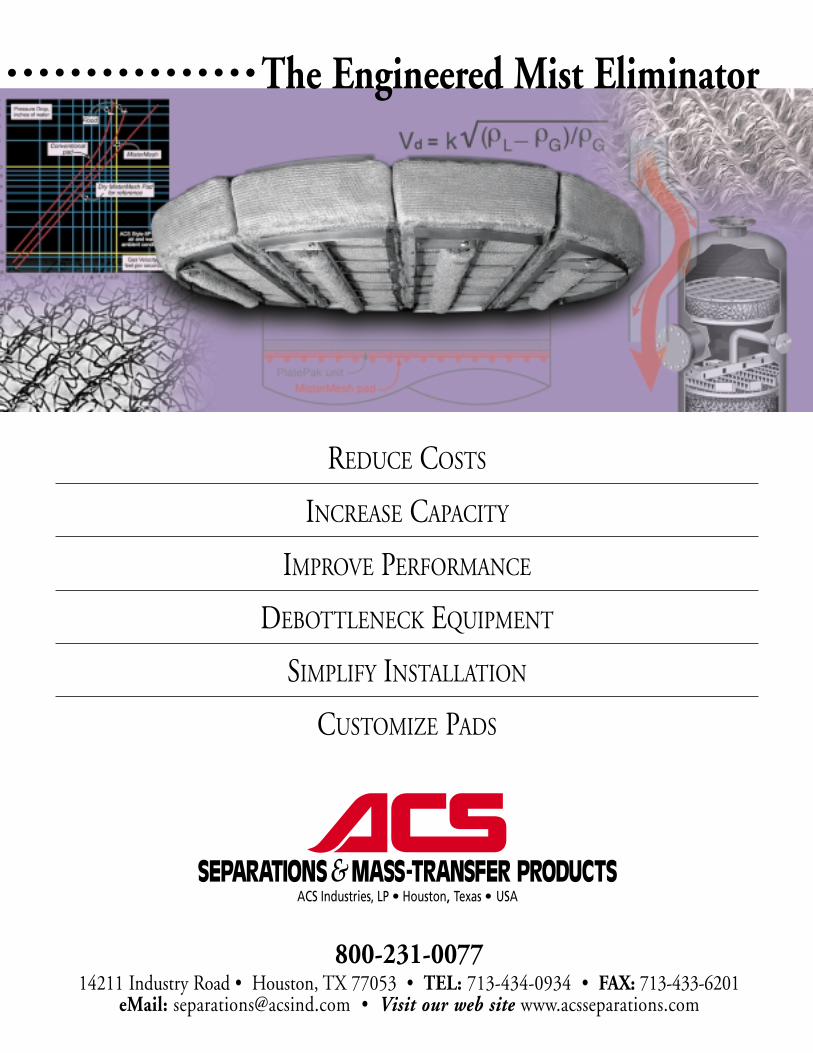
800-231-0077 14211 Industry Road • Houston, TX 77053 • TEL: 713-434-0934 • FAX: 713-433-6201 eMail: [email protected] • Visit our web site www.acsseparations.com The Engineered Mist Eliminator REDUCE COSTS INCREASE CAPACITY IMPROVE PERFORMANCE DEBOTTLENECK EQUIPMENT SIMPLIFY INSTALLATION CUSTOMIZE P ADS
-
Upload
william-novaes -
Category
Documents
-
view
241 -
download
17
Transcript of ACS Design Manual
800-231-007714211 Industry Road • Houston, TX 77053 • TEL: 713-434-0934 • FAX: 713-433-6201
eMail: [email protected] • Visit our web site www.acsseparations.com
The Engineered Mist Eliminator
REDUCE COSTS
INCREASE CAPACITY
IMPROVE PERFORMANCE
DEBOTTLENECK EQUIPMENT
SIMPLIFY INSTALLATION
CUSTOMIZE PADS
The Engineered Mist EliminatorMist elimination, or the removal of entrained liquid droplets from a vaporstream, is one of the most commonly encountered processes regardlessof unit operation. Unfortunately, mist eliminators are often consideredcommodity items and are specified without attention to available tech-nologies and design approaches. The engineered mist eliminator mayreduce liquid carryover by a factor of one hundred or more relative to astandard unit, drop head losses by 50% or more, or increase capacity byfactors of three or four. This manual summarizes cost effective approachesto reducing solvent losses or emissions, extending equipment life andmaintenance cycles using proven and cost effective technologies andtechniques.
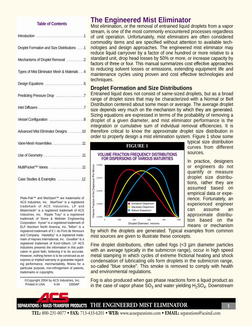
Droplet Formation and Size DistributionsEntrained liquid does not consist of same-sized droplets, but as a broadrange of droplet sizes that may be characterized with a Normal or BellDistribution centered about some mean or average. The average dropletsize depends very much on the mechanism by which they are generated.Sizing equations are expressed in terms of the probability of removing adroplet of a given diameter, and mist eliminator performance is theintegration or cumulative sum of individual removal efficiencies. It istherefore critical to know the approximate droplet size distribution inorder to properly design a mist elimination system. Figure 1 show some
typical size distributioncurves from differentsources.
In practice, designersor engineers do notquantify or measuredroplet size distribu-tions, rather they areassumed based onempirical data or expe-rience. Fortunately, anexperienced engineercan assume anapproximate distribu-tion based on themeans or mechanism
by which the droplets are generated. Typical examples from commonmist sources are given to illustrate these concepts.
Fine droplet distributions, often called fogs (<3 µm diameter particleswith an average typically in the submicron range), occur in high speedmetal stamping in which cycles of extreme frictional heating and shockcondensation of lubricating oils form droplets in the submicron range,so-called "blue smoke". This smoke is removed to comply with healthand environmental regulations.
Fog is also produced when gas phase reactions form a liquid product asin the case of vapor phase SO3 and water yielding H2SO4. Downstream
TEL: 800-231-0077 • FAX: 713-433-6201 • WEB: www.acsseparations.com • EMAIL: [email protected]
THE ENGINEERED MIST ELIMINATOR 1
Table of Contents
Introduction . . . . . . . . . . . . . . . . . . . . . . . . . . .1
Droplet Formation and Size Distributions . . . .1
Mechanisms of Droplet Removal . . . . . . . . . .2
Types of Mist Eliminator Mesh & Materials . . .4
Design Equations . . . . . . . . . . . . . . . . . . . . . .6
Predicting Pressure Drop . . . . . . . . . . . . . . . .7
Inlet Diffusers . . . . . . . . . . . . . . . . . . . . . . . . . .7
Vessel Configuration . . . . . . . . . . . . . . . . . . . .8
Advanced Mist Eliminator Designs . . . . . . . .10
Vane-Mesh Assemblies . . . . . . . . . . . . . . . . .11
Use of Geometry . . . . . . . . . . . . . . . . . . . . . .11
MultiPocket™ Vanes . . . . . . . . . . . . . . . . . . .11
Case Studies & Examples . . . . . . . . . . . . . .12
Plate-Pak™ and MistXpert™ are trademarks ofACS Industries, Inc. MaxFlow® is a registeredtrademark of ACS Industr ies, LP andMistermesh® is a registered trademark of ACSIndustries, Inc. Ripple Tray® is a registeredtrademark of Stone & Webster EngineeringCorporation. Kynar® is a registered trademark ofELF Atochem North America, Inc. Teflon® is aregistered trademark of E.I. du Pont de Nemoursand Company. Hastelloy® is a registered trade-mark of Haynes International, Inc. Goodloe® is aregistered trademark of Koch-Glitsch, LP. ACSIndustries presents the information in this publi-cation in good faith, believing it to be accurate.However, nothing herein is to be construed as anexpress or implied warranty or guarantee regard-ing performance, merchantability, fitness for aparticular purpose, non-infringement of patents,trademarks or copyrights.
©Copyright 2004 by ACS Industries, Inc,Printed in USA 4-04 1000AP
FIGURE 1
VOLUME FRACTION FREQUENCY DISTRIBUTIONSFOR DISPERSIONS OF VARIOUS MATURITIES
equipment corrodes rapidly without the removal of thisliquid. Similar concerns are found in ammonia prilltowers, many chlorine applications, as well asphosphoric and nitric acid plants.
A mist consists of droplets in the range of 3µm andgreater, though distributions with average diameters20 µm and greater are termed Sprays. Mist comingoff the top of packing or trays, or generated by surfaceevaporation, are typically in the broad range of 5-800 µm.In towers used in glycol dehydration and amine sweet-ening in which mists are a major source of costlysolvent losses, removal of droplets down to 5 µm isrecommended.
Hydraulic spray nozzles generate particles of diametersgreater than 50 µm and pneumatic nozzles greaterthan 10 µm, with upper limits reaching 1000 µm.
The first step in engineering a mist eliminator is todetermine the mechanism by which the droplets aregenerated and assume an average droplet size.Figure 2 summarizes typical particle size distributionscaused by various mechanisms:
This manual contains basic design concepts used byengineers to remove droplets greater than 3 µm indiameter, so called mists and sprays.
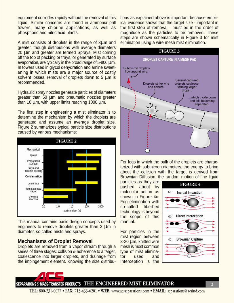
Mechanisms of Droplet RemovalDroplets are removed from a vapor stream through aseries of three stages: collision & adherence to a target,coalescence into larger droplets, and drainage fromthe impingement element. Knowing the size distribu-
tions as explained above is important because empir-ical evidence shows that the target size - important inthe first step of removal - must be in the order ofmagnitude as the particles to be removed. Thesesteps are shown schematically in Figure 3 for mistelimination using a wire mesh mist elimination.
For fogs in which the bulk of the droplets are charac-terized with submicron diameters, the energy to bringabout the collision with the target is derived fromBrownian Diffusion, the random motion of fine liquidparticles as they arepushed about bymolecular action asshown in Figure 4c.Fog elimination withso-called fiberbedtechnology is beyondthe scope of thismanual.
For particles in themist region between3-20 µm, knitted wiremesh is most commontype of mist elimina-tor used andInterception is the
TEL: 800-231-0077 • FAX: 713-433-6201 • WEB: www.acsseparations.com • EMAIL: [email protected]
THE ENGINEERED MIST ELIMINATOR 2
0.1 1.0 10 100 1000
Mechanical
Condensation
sprays
on surface
evaporationsurface
trays andcolumn packing
from saturatedvapor
chemicalreaction
particle size
FIGURE 2
FIGURE 3
DROPLET CAPTURE IN A MESH PAD
Inertial Impaction
Direct Interception
Brownian Capture
FIGURE 4
4a
4b
4c
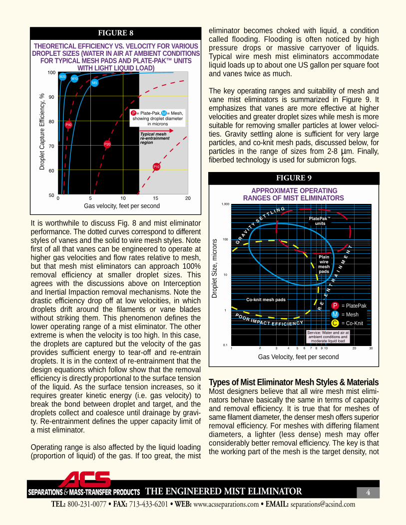
primary mechanism. Consider a droplet approachinga mesh filament of much larger diameter as shown inFigure 4b. The more dense the droplet relative to thegas, the larger the droplet relative to the filament, andthe higher the gas velocity, the more likely it is that thedroplet will strike the filament. If the velocity is too low,or the droplet too small or too light compared to thegas, the droplet will simply flow around the filamentwith the gas. If the velocity is too high, liquid clingingto the filaments will be re-entrained, mostly as largerdroplets, and carried away by the gas. Re-entrain-ment is also promoted by low relative liquid density(making it easier for the gas to pick up a droplet) andlow liquid surface tension (as less energy is requiredto break up a film or droplet). The engineered wiremesh mist eliminator may remove 99.9% of particles2 µm and greater diameter. Figure 5 shows a typicalremoval efficiency vs droplet size distribution for awire mesh mist eliminator.
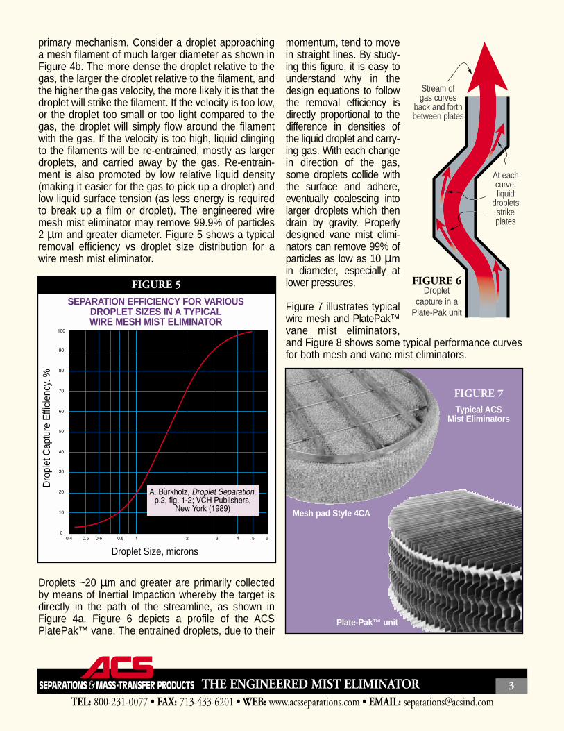
Droplets ~20 µm and greater are primarily collectedby means of Inertial Impaction whereby the target isdirectly in the path of the streamline, as shown inFigure 4a. Figure 6 depicts a profile of the ACSPlatePak™ vane. The entrained droplets, due to their
momentum, tend to movein straight lines. By study-ing this figure, it is easy tounderstand why in thedesign equations to followthe removal efficiency isdirectly proportional to thedifference in densities ofthe liquid droplet and carry-ing gas. With each changein direction of the gas,some droplets collide withthe surface and adhere,eventually coalescing intolarger droplets which thendrain by gravity. Properlydesigned vane mist elimi-nators can remove 99% ofparticles as low as 10 µmin diameter, especially atlower pressures.
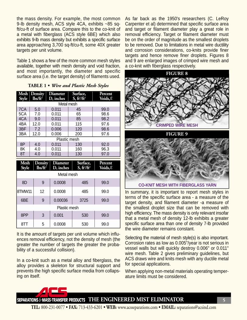
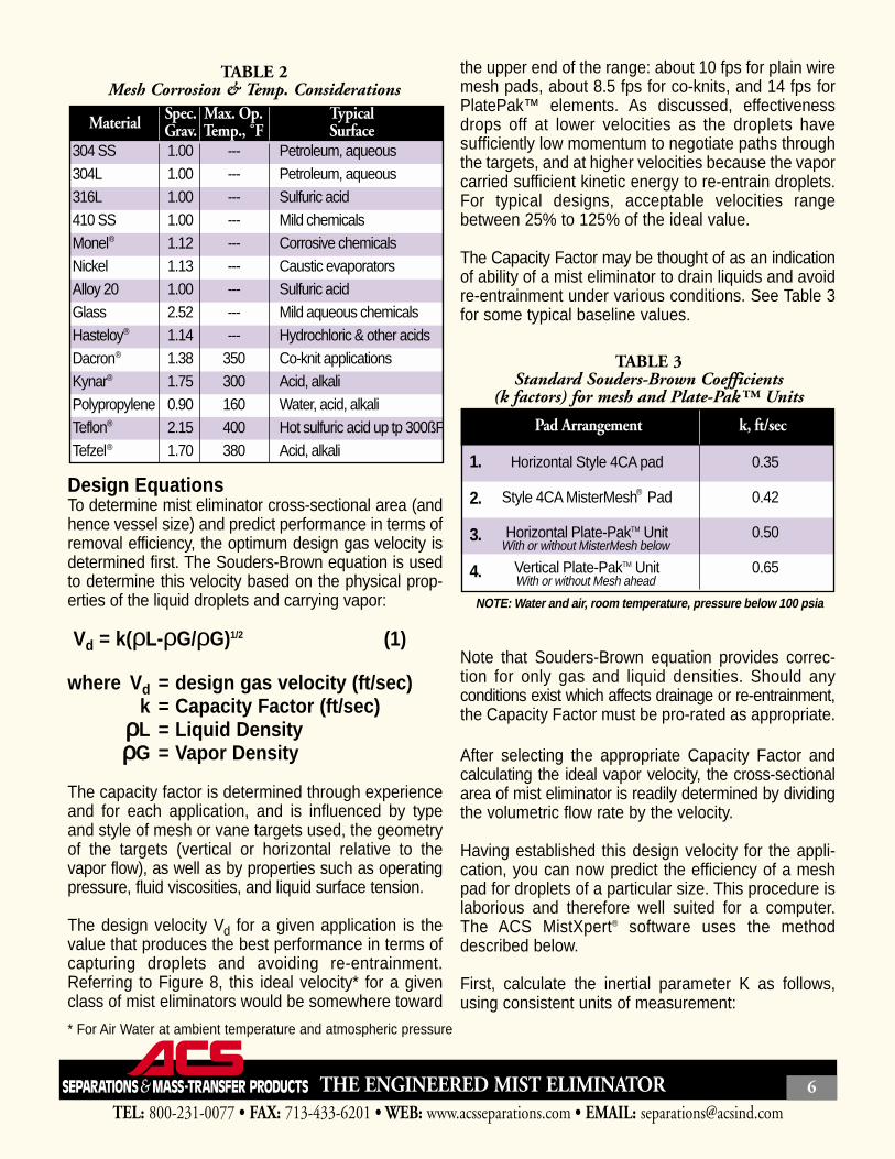
Figure 7 illustrates typicalwire mesh and PlatePak™vane mist eliminators,and Figure 8 shows some typical performance curvesfor both mesh and vane mist eliminators.
TEL: 800-231-0077 • FAX: 713-433-6201 • WEB: www.acsseparations.com • EMAIL: [email protected]
THE ENGINEERED MIST ELIMINATOR 3
FIGURE 6Droplet
capture in aPlate-Pak unit
Stream ofgas curves
back and forthbetween plates
At eachcurve,liquid
dropletsstrikeplates
Droplet Size, microns
Dro
plet
Cap
ture
Effi
cien
cy. %
SEPARATION EFFICIENCY FOR VARIOUSDROPLET SIZES IN A TYPICALWIRE MESH MIST ELIMINATOR
FIGURE 5
FIGURE 7
Typical ACSMist Eliminators
Mesh pad Style 4CA
Plate-Pak™ unit
It is worthwhile to discuss Fig. 8 and mist eliminatorperformance. The dotted curves correspond to differentstyles of vanes and the solid to wire mesh styles. Notefirst of all that vanes can be engineered to operate athigher gas velocities and flow rates relative to mesh,but that mesh mist eliminators can approach 100%removal efficiency at smaller droplet sizes. Thisagrees with the discussions above on Interceptionand Inertial Impaction removal mechanisms. Note thedrastic efficiency drop off at low velocities, in whichdroplets drift around the filaments or vane bladeswithout striking them. This phenomenon defines thelower operating range of a mist eliminator. The otherextreme is when the velocity is too high. In this case,the droplets are captured but the velocity of the gasprovides sufficient energy to tear-off and re-entraindroplets. It is in the context of re-entrainment that thedesign equations which follow show that the removalefficiency is directly proportional to the surface tensionof the liquid. As the surface tension increases, so itrequires greater kinetic energy (i.e. gas velocity) tobreak the bond between droplet and target, and thedroplets collect and coalesce until drainage by gravi-ty. Re-entrainment defines the upper capacity limit ofa mist eliminator.
Operating range is also affected by the liquid loading(proportion of liquid) of the gas. If too great, the mist
eliminator becomes choked with liquid, a conditioncalled flooding. Flooding is often noticed by highpressure drops or massive carryover of liquids.Typical wire mesh mist eliminators accommodateliquid loads up to about one US gallon per square footand vanes twice as much.
The key operating ranges and suitability of mesh andvane mist eliminators is summarized in Figure 9. Itemphasizes that vanes are more effective at highervelocities and greater droplet sizes while mesh is moresuitable for removing smaller particles at lower veloci-ties. Gravity settling alone is sufficient for very largeparticles, and co-knit mesh pads, discussed below, forparticles in the range of sizes from 2-8 µm. Finally,fiberbed technology is used for submicron fogs.
Types of Mist Eliminator Mesh Styles & MaterialsMost designers believe that all wire mesh mist elimi-nators behave basically the same in terms of capacityand removal efficiency. It is true that for meshes ofsame filament diameter, the denser mesh offers superiorremoval efficiency. For meshes with differing filamentdiameters, a lighter (less dense) mesh may offerconsiderably better removal efficiency. The key is thatthe working part of the mesh is the target density, not
TEL: 800-231-0077 • FAX: 713-433-6201 • WEB: www.acsseparations.com • EMAIL: [email protected]
THE ENGINEERED MIST ELIMINATOR 4
Gas velocity, feet per second
Dro
plet
Cap
ture
Effi
cien
cy, %
THEORETICAL EFFICIENCY VS. VELOCITY FOR VARIOUS DROPLET SIZES (WATER IN AIR AT AMBIENT CONDITIONS
FOR TYPICAL MESH PADS AND PLATE-PAK™ UNITSWITH LIGHT LIQUID LOAD)
FIGURE 8
Gas Velocity, feet per second
Dro
plet
Siz
e, m
icro
ns
.2, fig 1-2 VCH PublisheNew York (1989)
P = PlatePak
M = Mesh
C = Co-Knit
APPROXIMATE OPERATINGRANGES OF MIST ELIMINATORS
FIGURE 9
the mass density. For example, the most common9-lb density mesh, ACS style 4CA, exhibits ~85 sq-ft/cu-ft of surface area. Compare this to the co-knit ofa metal with fiberglass (ACS style 6BE) which alsoexhibits 9-lb mass density but exhibits a specific surfacearea approaching 3,700 sq-ft/cu-ft, some 40X greatertargets per unit volume.
Table 1 shows a few of the more common mesh stylesavailable, together with mesh density and void fraction,and most importantly, the diameter and specificsurface area (i.e. the target density) of filaments used.
It is the amount of targets per unit volume which influ-ences removal efficiency, not the density of mesh (thegreater the number of targets the greater the proba-bility of a successful collision).
In a co-knit such as a metal alloy and fiberglass, thealloy provides a skeleton for structural support andprevents the high specific surface media from collaps-ing on itself.
As far back as the 1950's researchers (C. LeRoyCarpenter et al) determined that specific surface areaand target or filament diameter play a great role inremoval efficiency. Target or filament diameter mustbe on the order of magnitude as the smallest dropletsto be removed. Due to limitations in metal wire ductilityand corrosion considerations, co-knits provide finertargets and hence remove finer droplets. Figures 8and 9 are enlarged images of crimped wire mesh anda co-knit with fiberglass respectively.
In summary, it is important to report mesh styles interms of the specific surface area - a measure of thetarget density, and filament diameter -a measure ofthe smallest droplet size that can be removed withhigh efficiency. The mass density is only relevant insofarthat a metal mesh of density 12-lb exhibits a greaterspecific surface area than one of density 7-lb providedthe wire diameter remains constant.
Selecting the material of mesh style(s) is also important.Corrosion rates as low as 0.005"/year is not serious invessel walls but will quickly destroy 0.006" or 0.011"wire mesh. Table 2 gives preliminary guidelines, butACS draws wire and knits mesh with any ductile metalfor special applications.
When applying non-metal materials operating temper-ature limits must be considered.
TEL: 800-231-0077 • FAX: 713-433-6201 • WEB: www.acsseparations.com • EMAIL: [email protected]
THE ENGINEERED MIST ELIMINATOR 5
7CAMetal mesh
Plastic mesh
5CA4CA
8P8K8T
4BA3BF3BA
MeshStyle
5.07.09.0
4.04.04.0
12.07.2
12.0
Densitylbs/ft3
456585
130160130
115120200
Surface,S, ft2/ft3
99.098.698.2
92.096.397.0
97.698.697.6
PercentVoids,
0.0110.0110.011
0.0110.0110.011
0.0110.0060.006
DiameterD, inches
8D
Metal mesh
Plastic mesh
MeshStyle
9
Densitylbs/ft3
485
Surface,S, ft2/ft3
99.0
PercentVoids,
0.0008
DiameterD, inches
8TMW11 12 485 99.00.0008
8PP 3 530 99.00.001
8TT 5 530 99.00.0008
6BE 9 3725 99.00.00036
TABLE 1 • Wire and Plastic Mesh Styles
CRIMPED WIRE MESH
CO-KNIT MESH WITH FIBERGLASS YARN
FIGURE 8
FIGURE 9
Design EquationsTo determine mist eliminator cross-sectional area (andhence vessel size) and predict performance in terms ofremoval efficiency, the optimum design gas velocity isdetermined first. The Souders-Brown equation is usedto determine this velocity based on the physical prop-erties of the liquid droplets and carrying vapor:
Vd = k(ρL-ρG/ρG)1/2 (1)
where Vd = design gas velocity (ft/sec)k = Capacity Factor (ft/sec)
ρρL = Liquid DensityρρG = Vapor Density
The capacity factor is determined through experienceand for each application, and is influenced by typeand style of mesh or vane targets used, the geometryof the targets (vertical or horizontal relative to thevapor flow), as well as by properties such as operatingpressure, fluid viscosities, and liquid surface tension.
The design velocity Vd for a given application is thevalue that produces the best performance in terms ofcapturing droplets and avoiding re-entrainment.Referring to Figure 8, this ideal velocity* for a givenclass of mist eliminators would be somewhere toward
the upper end of the range: about 10 fps for plain wiremesh pads, about 8.5 fps for co-knits, and 14 fps forPlatePak™ elements. As discussed, effectivenessdrops off at lower velocities as the droplets havesufficiently low momentum to negotiate paths throughthe targets, and at higher velocities because the vaporcarried sufficient kinetic energy to re-entrain droplets.For typical designs, acceptable velocities rangebetween 25% to 125% of the ideal value.
The Capacity Factor may be thought of as an indicationof ability of a mist eliminator to drain liquids and avoidre-entrainment under various conditions. See Table 3for some typical baseline values.
Note that Souders-Brown equation provides correc-tion for only gas and liquid densities. Should anyconditions exist which affects drainage or re-entrainment,the Capacity Factor must be pro-rated as appropriate.
After selecting the appropriate Capacity Factor andcalculating the ideal vapor velocity, the cross-sectionalarea of mist eliminator is readily determined by dividingthe volumetric flow rate by the velocity.
Having established this design velocity for the appli-cation, you can now predict the efficiency of a meshpad for droplets of a particular size. This procedure islaborious and therefore well suited for a computer.The ACS MistXpert® software uses the methoddescribed below.
First, calculate the inertial parameter K as follows,using consistent units of measurement:
TEL: 800-231-0077 • FAX: 713-433-6201 • WEB: www.acsseparations.com • EMAIL: [email protected]
THE ENGINEERED MIST ELIMINATOR 6
304 SS304L316L410 SSMonelNickelAlloy 20GlassHasteloyDacronKynarPolypropyleneTeflonTefzel
1.001.001.001.001.121.131.002.521.141.381.750.902.151.70
---------------------------
350300160400380
Petroleum, aqueousPetroleum, aqueousSulfuric acidMild chemicalsCorrosive chemicalsCaustic evaporatorsSulfuric acidMild aqueous chemicals Hydrochloric & other acidsCo-knit applicationsAcid, alkaliWater, acid, alkaliHot sulfuric acid up tp 300ßFAcid, alkali
Material Max. Op.Temp., ˚F
TypicalSurface
Spec.Grav.
TABLE 2Mesh Corrosion & Temp. Considerations
0.35
0.42
0.50
0.65With or without MisterMesh below
With or without Mesh ahead
NOTE: Water and air, room temperature, pressure below 100 psia
Horizontal Style 4CA pad
Style 4CA MisterMesh Pad
Horizontal Plate-PakTM Unit
Vertical Plate-PakTM Unit
1.
2.
3.
4.
Pad Arrangement k, ft/sec
TABLE 3Standard Souders-Brown Coefficients
(k factors) for mesh and Plate-Pak™ Units
* For Air Water at ambient temperature and atmospheric pressure
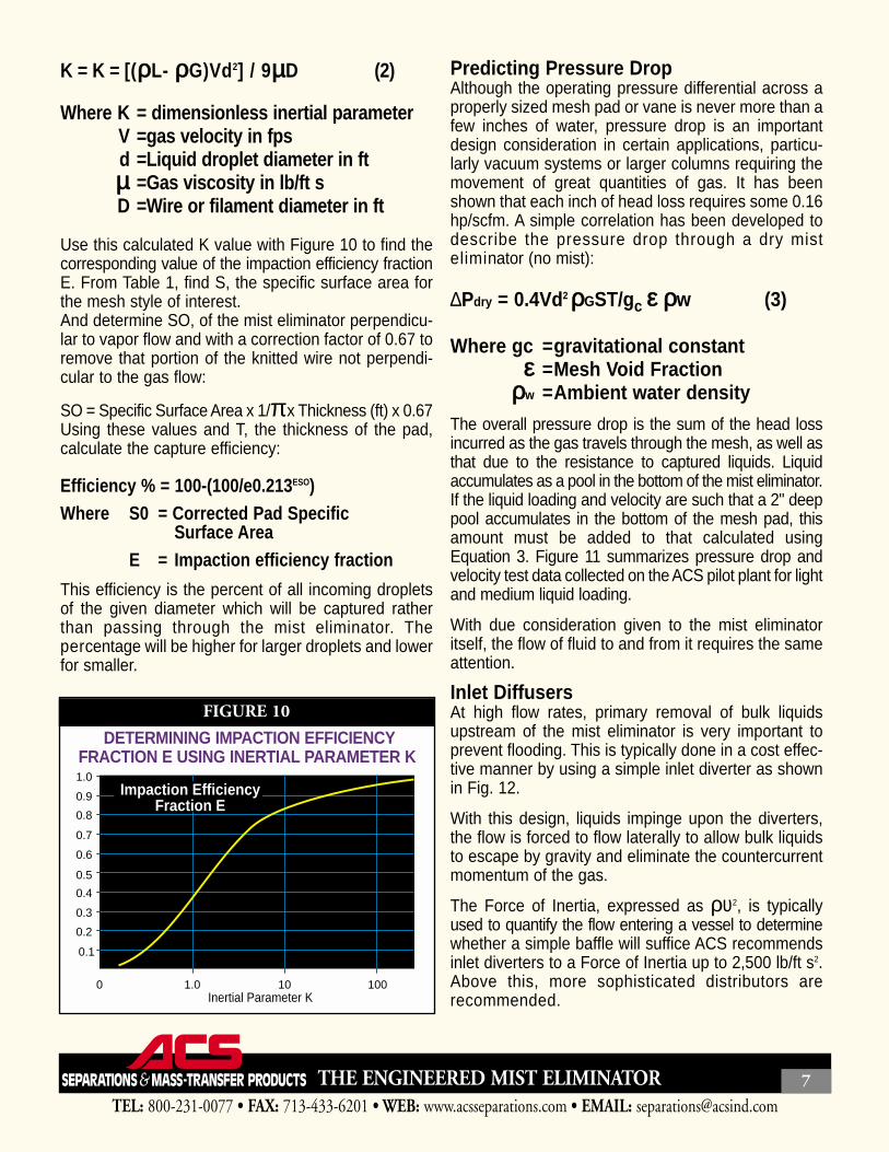
K = K = [(ρρL- ρρG)Vd2] / 9µµD (2)
Where K = dimensionless inertial parameterV =gas velocity in fpsd =Liquid droplet diameter in ftµµ =Gas viscosity in lb/ft sD =Wire or filament diameter in ft
Use this calculated K value with Figure 10 to find thecorresponding value of the impaction efficiency fractionE. From Table 1, find S, the specific surface area forthe mesh style of interest. And determine SO, of the mist eliminator perpendicu-lar to vapor flow and with a correction factor of 0.67 toremove that portion of the knitted wire not perpendi-cular to the gas flow:
SO = Specific Surface Area x 1/πx Thickness (ft) x 0.67Using these values and T, the thickness of the pad,calculate the capture efficiency:
Efficiency % = 100-(100/e0.213ESO)Where S0 = Corrected Pad Specific
Surface AreaE = Impaction efficiency fraction
This efficiency is the percent of all incoming dropletsof the given diameter which will be captured ratherthan passing through the mist eliminator. Thepercentage will be higher for larger droplets and lowerfor smaller.
Predicting Pressure DropAlthough the operating pressure differential across aproperly sized mesh pad or vane is never more than afew inches of water, pressure drop is an importantdesign consideration in certain applications, particu-larly vacuum systems or larger columns requiring themovement of great quantities of gas. It has beenshown that each inch of head loss requires some 0.16hp/scfm. A simple correlation has been developed todescribe the pressure drop through a dry misteliminator (no mist):
∆Pdry = 0.4Vd2 ρρGST/gc εε ρρw (3)
Where gc =gravitational constantεε =Mesh Void Fraction
ρρw =Ambient water density
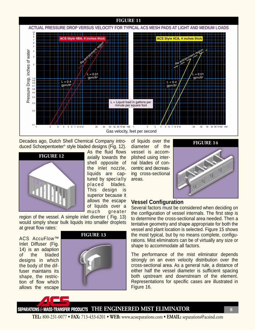
The overall pressure drop is the sum of the head lossincurred as the gas travels through the mesh, as well asthat due to the resistance to captured liquids. Liquidaccumulates as a pool in the bottom of the mist eliminator.If the liquid loading and velocity are such that a 2" deeppool accumulates in the bottom of the mesh pad, thisamount must be added to that calculated usingEquation 3. Figure 11 summarizes pressure drop andvelocity test data collected on the ACS pilot plant for lightand medium liquid loading.
With due consideration given to the mist eliminatoritself, the flow of fluid to and from it requires the sameattention.
Inlet DiffusersAt high flow rates, primary removal of bulk liquidsupstream of the mist eliminator is very important toprevent flooding. This is typically done in a cost effec-tive manner by using a simple inlet diverter as shownin Fig. 12.
With this design, liquids impinge upon the diverters,the flow is forced to flow laterally to allow bulk liquidsto escape by gravity and eliminate the countercurrentmomentum of the gas.
The Force of Inertia, expressed as ρυ2, is typicallyused to quantify the flow entering a vessel to determinewhether a simple baffle will suffice ACS recommendsinlet diverters to a Force of Inertia up to 2,500 lb/ft s2.Above this, more sophisticated distributors arerecommended.
TEL: 800-231-0077 • FAX: 713-433-6201 • WEB: www.acsseparations.com • EMAIL: [email protected]
THE ENGINEERED MIST ELIMINATOR 7
0 1.0 10 100Inertial Parameter K
1.0
0.9
0.8
0.7
0.6
0.5
0.4
0.3
0.2
0.1
Impaction EfficiencyFraction E
DETERMINING IMPACTION EFFICIENCYFRACTION E USING INERTIAL PARAMETER K
FIGURE 10
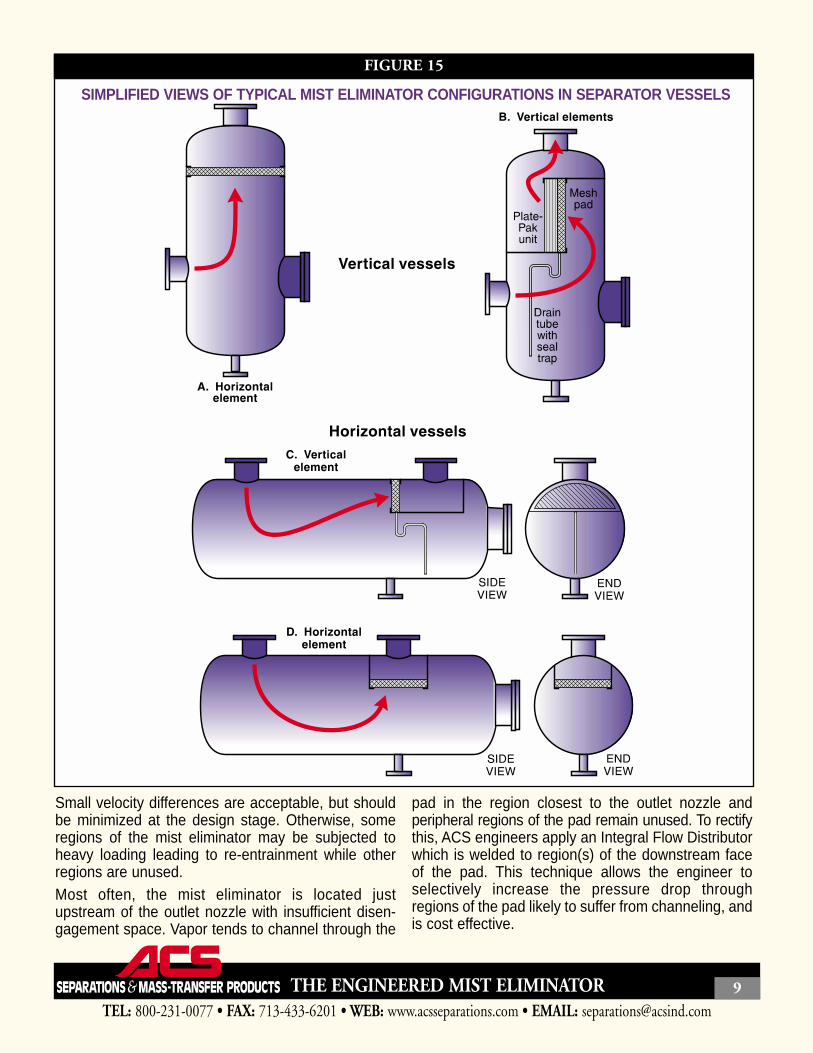
Decades ago, Dutch Shell Chemical Company intro-duced Schoepentoeter® style bladed designs (Fig. 12).
As the fluid flowsaxially towards theshell opposite ofthe inlet nozzle,liquids are cap-tured by spec ia l lyp laced blades.This design issuperior because itallows the escapeof liquids over amuch g rea te r
region of the vessel. A simple inlet diverter ( Fig. 13)would simply shear bulk liquids into smaller dropletsat great flow rates:
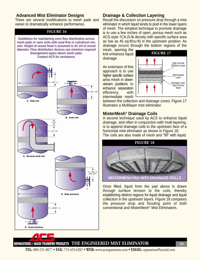
ACS AccuFlow™Inlet Diffuser (Fig.14) is an adaptionof the bladeddesigns in whichthe body of the dif-fuser maintains itsshape, the restric-tion of flow whichallows the escape
of liquids over thediameter of thevessel is accom-plished using inter-nal blades of con-centric and decreas-ing cross-sectionalareas.
Vessel Configuration Several factors must be considered when deciding onthe configuration of vessel internals. The first step isto determine the cross-sectional area needed. Then atentative geometry and shape appropriate for both thevessel and plant location is selected. Figure 15 showsthe most typical, but by no means complete, configu-rations. Mist eliminators can be of virtually any size orshape to accommodate all factors.
The performance of the mist eliminator dependsstrongly on an even velocity distribution over thecross-sectional area. As a general rule, a distance ofeither half the vessel diameter is sufficient spacingboth upstream and downstream of the element.Representations for specific cases are illustrated inFigure 16.
TEL: 800-231-0077 • FAX: 713-433-6201 • WEB: www.acsseparations.com • EMAIL: [email protected]
THE ENGINEERED MIST ELIMINATOR 8
Gas velocity, feet per second
Pre
ssur
e D
rop,
inch
es o
f wat
erACTUAL PRESSURE DROP VERSUS VELOCITY FOR TYPICAL ACS MESH PADS AT LIGHT AND MEDIUM LOADS
FIGURE 11
FIGURE 12
FIGURE 13
FIGURE 14
Small velocity differences are acceptable, but shouldbe minimized at the design stage. Otherwise, someregions of the mist eliminator may be subjected toheavy loading leading to re-entrainment while otherregions are unused. Most often, the mist eliminator is located justupstream of the outlet nozzle with insufficient disen-gagement space. Vapor tends to channel through the
pad in the region closest to the outlet nozzle andperipheral regions of the pad remain unused. To rectifythis, ACS engineers apply an Integral Flow Distributorwhich is welded to region(s) of the downstream faceof the pad. This technique allows the engineer toselectively increase the pressure drop throughregions of the pad likely to suffer from channeling, andis cost effective.
TEL: 800-231-0077 • FAX: 713-433-6201 • WEB: www.acsseparations.com • EMAIL: [email protected]
THE ENGINEERED MIST ELIMINATOR 9
SIMPLIFIED VIEWS OF TYPICAL MIST ELIMINATOR CONFIGURATIONS IN SEPARATOR VESSELS
FIGURE 15
Advanced Mist Eliminator DesignsThere are several modifications to mesh pads andvanes to dramatically enhance performance.
Drainage & Collection LayeringRecall the discussion on pressure drop through a misteliminator in which liquid tends to pool in the lower layersof mesh. The simplest technique to promote drainageis to use a few inches of open, porous mesh such asACS style 7CA (5-lb density with specific surface areaas low as 45 sq-ft/cu-ft) in the upstream position. Asdrainage occurs through the bottom regions of themesh, opening theknit enhances liquiddrainage.
An extension of thisapproach is to usehigher specific surfacearea mesh in down-stream positions toenhance separationefficiency, withintermediate meshbetween the collection and drainage zones. Figure 17illustrates a Multilayer mist eliminator.
MisterMesh® Drainage CoilsA second technique used by ACS to enhance liquiddrainage, and often in conjunction with multi-layering,is to append drainage coils to the upstream face of ahorizontal mist eliminator as shown in Figure 18. The coils are also made of mesh and "fill" with liquid.
Once filled, liquid from the pad above is drawnthrough surface tension to the coils, therebyestablishing distinct regions for liquid drainage and liquidcollection in the upstream layers. Figure 18 comparesthe pressure drop and flooding point of bothconventional and MisterMesh® Mist Eliminators.
TEL: 800-231-0077 • FAX: 713-433-6201 • WEB: www.acsseparations.com • EMAIL: [email protected]
THE ENGINEERED MIST ELIMINATOR 10
Guidelines for maintaining even flow distribution acrossmesh pads or vane units with axial flow in cylindrical ves-sels. Height of vessel head is assumed to be 1/4 of vesseldiameter. Flow distribution devices can minimize required
disengement space above mesh pads.Contact ACS for assistance.
FIGURE 16
High removalEfficiency Layer
IntermediateLayer
Drainage Layer,Open Porous
Mesh
FIGURE 17
MISTERMESH PAD WITH DRAINAGE ROLLS
FIGURE 18
Mesh-Vane AssembliesIn grass root design of larger vessels and retrofit ofexisting ones to accommodate greater flow rates, mesh-vane assemblies are often used. In an assembly, meshis placed upstream of the vane and acts as a floodedagglomerator. The Capacity Factor used corresponds tothe downstream vane element. This approach com-bines the efficiency of mesh with the capacity of vanesand has been used by ACS engineers with tremendoussuccess over the past two decades.
Throughout the industry there is ongoing debate as towhether the mesh should be positioned up- or down-stream of the vane element. Engineers at ACS haveperformed exhaustive comparative testing on pilotplants and have much field data proving that the meshis indeed affective upstream of the vane, unless thevane element is used as a pre-filter to protect a down-stream mesh pad.
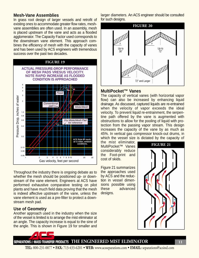
Use of GeometryAnother approach used in the industry when the sizeof the vessel is limited is to arrange the mist eliminator atan angle. The capacity increase is equal to the sine ofthe angle. This is shown in Figure 19 for smaller and
larger diameters. An ACS engineer should be consultedfor such designs.
MultiPocket™ VanesThe capacity of vertical vanes (with horizontal vaporflow) can also be increased by enhancing liquiddrainage. As discussed, captured liquids are re-entrainedwhen the velocity of vapor exceeds the idealvelocity. To prevent liquid re-entrainment, the serpen-tine path offered by the vane is augmented withobstructions to allow for the pooling of liquid with pro-tection from the passing vapor stream. This designincreases the capacity of the vane by as much as45%. In vertical gas compressor knock-out drums, inwhich the vessel size is dictated by the capacity ofthe mist eliminator,MultiPocket™ Vanesconsiderably reducethe Foot-print andcost of skids.
Figure 21 summarizesthe approaches usedby ACS and the reduc-tion in vessel dimen-sions possible usingthese advanceddesigns.
TEL: 800-231-0077 • FAX: 713-433-6201 • WEB: www.acsseparations.com • EMAIL: [email protected]
THE ENGINEERED MIST ELIMINATOR 11
Dry MisterMesh Padfor reference
MisterMesh
Gas velocity, feet per second
Pre
ssur
e D
rop,
inch
es o
f wat
er
ACS Style 8P mesh, air & water, ambient
conditions.
ACTUAL PRESSURE-DROP PERFORMANCEOF MESH PADS VRESUS VELOCITY.NOTE RAPID INCREASE AS FLOODED
CONDITION IS APPROACHED
FIGURE 19
Up to36"
Up to72"
72" and Larger
FIGURE 20
FIGURE 21
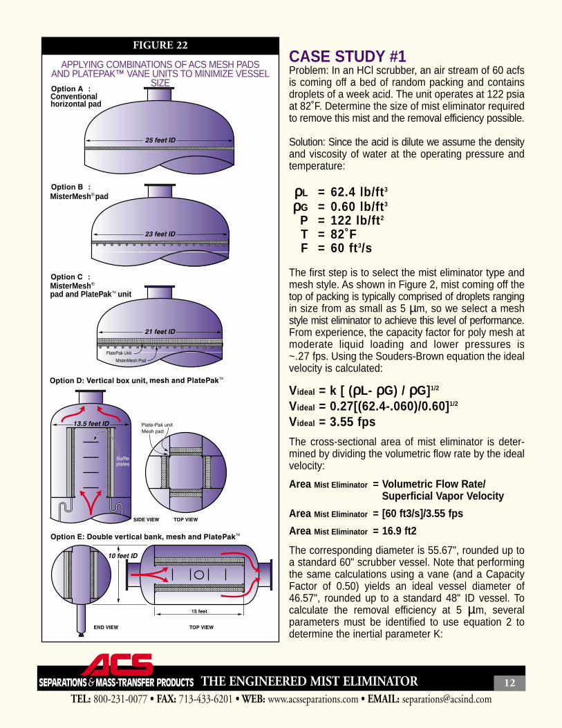
CASE STUDY #1Problem: In an HCl scrubber, an air stream of 60 acfsis coming off a bed of random packing and containsdroplets of a week acid. The unit operates at 122 psiaat 82˚F. Determine the size of mist eliminator requiredto remove this mist and the removal efficiency possible.
Solution: Since the acid is dilute we assume the densityand viscosity of water at the operating pressure andtemperature:
ρρL = 62.4 lb/ft3
ρρG = 0.60 lb/ft3
P = 122 lb/ft2
T = 82˚FF = 60 ft3/s
The first step is to select the mist eliminator type andmesh style. As shown in Figure 2, mist coming off thetop of packing is typically comprised of droplets rangingin size from as small as 5 µm, so we select a meshstyle mist eliminator to achieve this level of performance.From experience, the capacity factor for poly mesh atmoderate liquid loading and lower pressures is~.27 fps. Using the Souders-Brown equation the idealvelocity is calculated:
Videal = k [ (ρρL- ρρG) / ρρG]1/2
Videal = 0.27[(62.4-.060)/0.60]1/2
Videal = 3.55 fps
The cross-sectional area of mist eliminator is deter-mined by dividing the volumetric flow rate by the idealvelocity:
Area Mist Eliminator = Volumetric Flow Rate/ Superficial Vapor Velocity
Area Mist Eliminator = [60 ft3/s]/3.55 fps
Area Mist Eliminator = 16.9 ft2
The corresponding diameter is 55.67", rounded up toa standard 60" scrubber vessel. Note that performingthe same calculations using a vane (and a CapacityFactor of 0.50) yields an ideal vessel diameter of46.57", rounded up to a standard 48" ID vessel. Tocalculate the removal efficiency at 5 µm, severalparameters must be identified to use equation 2 todetermine the inertial parameter K:
TEL: 800-231-0077 • FAX: 713-433-6201 • WEB: www.acsseparations.com • EMAIL: [email protected]
THE ENGINEERED MIST ELIMINATOR 12
MisterMesh pad
Conventionalhorizontal pad
MisterMeshpad and PlatePak unit
MisterMesh Pad
PlatePak Unit
APPLYING COMBINATIONS OF ACS MESH PADSAND PLATEPAK™ VANE UNITS TO MINIMIZE VESSEL
SIZE
FIGURE 22
K = [(ρρL- ρρG)Vd2]/9µµDK = 0.54
From Figure 10, the corresponding ImpactionEfficiency Fraction E is ~0.15. In the RemovalEfficiency Equation there is a term for the correctedspecific surface area SO:
SO= Specific Surface Area x 1/ππx Thickness (ft) x 0.67
For ACS style 8P, the specific surface area is (185 + 36) = 221 ft2/ft3, we will try both 4" and 6" thickmist eliminator thicknesses (1/3 and 1/2ft):
SO = 221 x 1/3.14 x 1/3 x 0.67SO 4"thick = 15.7 and SO 6"thick = 23.6
And Removal Efficiency E at 5 µµm is:Efficiency = 100 – 100/eESO
Efficiency = 100 – 100/e(0.15)(15.7)Efficiency = 90.5%
For the 6" thick element, the removal efficiency is97.1%. By using a composite pad containing a 2"layer of regular monofilament polypropylene, style 8P,upstream of a 2" thick layer of 8PP, mono- andmulti-filament co-knit, the removal efficiency is 99.9% .
CASE STUDY #2Traditionally, trays are used to bring about contactbetween glycol and natural gas in dehydration con-tactors. In recent years, the industry moved towardssmaller diameter columns by exploiting the highercapacities achieved with structured packing.However, the lower capital investment associated witha smaller diameter packed tower is often offset bydramatically increased glycol losses.
Consider a mid-western sour gas plant operating a96" glycol contactor and processing 1,310,000 lb/hr ofgas at 116˚F and 1214 psia. The gas and liquid specificdensities were 4.4 and 68 lb/cu-ft respectively. Theplant was experiencing 0.13 US gal of carryover permmscf, amounting to some 65 gal/day of lost triethyleneglycol, several hundred dollars worth per day. A 10"thick wire mesh mist eliminator of 12-lb mass density
was installed above the packing.From experience, ACS engineers knew that thedroplet size distribution for glycol coming off the top ofa packed dehydrator extends down to diametersof 5 µm and greater. Also, if the diameter of thepacked column was sized in accordance with thehydraulic requirements of the packing, the wire meshmist eliminator would be undersized.
The capacity factor for 12-lb density mesh in this serv-ice is ~0.23 – 0.27, having been de-rated for the highliquid viscosity of 18 cP (which retards liquid drainage)and relatively high operating pressure. Using the gasdensity, volumetric flow rate and cross-sectional areaof the mist eliminator, the actual superficial velocity isreadily calculated. Next, using known densities of thegas and glycol, the actual or operating CapacityFactor k is determined:
Vactual = kactual [(ρρL- ρρG) / ρρG]1/2
Re-arranging forkactual = Vactual / [(ρρL- ρρG) / ρρG]1/2
= 0.44 fps
A Capacity Factor of 0.44 fps is almost twice as highas the optimum, and is in the range of that of an ACSPlatePak™ Vane mist eliminator. However, the vanewill not remove particles down to 5 µm, so a mesh-vane assembly was proposed. The assembly has amultilayered mesh section with open, porous mesh(ACS style 7CA) upstream of high specific surfacearea mesh (8D(T) co-knit of stainless and Dacron®).MisterMesh® drainage coils were appended to thebottom face of the mist eliminator. Downstream of themesh was placed a PlatePak™ Vane. The totalthickness was 12" and was accommodated using thesame supports as the mist eliminator it replaced.
Carryover from a glycol contactor occurs through twomechanisms, evaporative losses and mechanical(carryover) losse). In this example, simulationsshowed evaporative glycol losses of 0.0054gal/mmscfd. The total losses after the revamp wereless than 0.008 gal/mmscfd, and carryover losses hadbeen reduced from 0.13 gal/mmscfd, a 94% reduction!
TEL: 800-231-0077 • FAX: 713-433-6201 • WEB: www.acsseparations.com • EMAIL: [email protected]
THE ENGINEERED MIST ELIMINATOR 13
TEL: 800-231-0077 • FAX: 713-433-6201 • WEB: www.acsseparations.com • EMAIL: [email protected]
THE ENGINEERED MIST ELIMINATOR 14
24-hour emergency service • Free technical support • 50 years experience
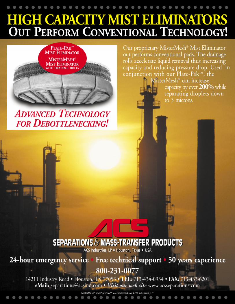
Our proprietary MisterMesh® Mist Eliminatorout performs conventional pads. The drainagerolls accelerate liquid removal thus increasingcapacity and reducing pressure drop. Used inconjunction with our Plate-Pak™, the
MisterMesh® can increasecapacity by over 200% while separating droplets down to 3 microns.
PLATE-PAK™
MIST ELIMINATOR
MISTERMESH®
MIST ELIMINATORWITH DRAINAGE ROLLS
ADVANCED TECHNOLOGYFOR DEBOTTLENECKING!
OUT PERFORM CONVENTIONAL TECHNOLOGY!HIGH CAPACITY MIST ELIMINATORS
800-231-007714211 Industry Road • Houston, TX 77053 • TEL: 713-434-0934 • FAX: 713-433-6201
eMail: [email protected] • Visit our web site www.acsseparations.comMisterMesh® and PlatePak™ are trademarks of ACS Industries, LP