
ACS – Actuator Control Solutions
46
HARDWARE & INSTALLATION GUIDE LINEAR SOLUTIONS MADE EASY LINEAR SOLUTIONS MADE EASY 3604-4181_05_ACS_SER ACS – Actuator Control Solutions Servo Drive/Controller and Motors ACS SERVO
Transcript of ACS – Actuator Control Solutions
HARDWARE & INSTALLATION GUIDE
LINEAR SOLUTIONS MADE EASYLINEAR SOLUTIONS MADE EASY
3604-4181_05_ACS_Servo_Hdw
ACS – Actuator Control SolutionsServo drive/Controller and Motors
ACS Servo

Tolomatic reserves the right to change the design or operation of the equipment described herein and any associated motion products without notice. Information in this document is subject to change without notice.
201411111743
Tolomatic Hardware & Installation Guide: ACS Servo Drive/Controller • i •
ContentsList of Figures ................................................................................................. iii
List of Tables................................................................................................... iv
Health and Safety Regulations........................................................................ v
Safety Symbols ....................................................................................................... v
EMC Wiring Guidelines ........................................................................................... vi
Proper and Safe Use of Product .............................................................................. vi
Handling and Unpacking ........................................................................................ vii
Product Warnings .................................................................................................. vii
1. Product Overview .................................................................................... 1_1
1.1 The ACS Servo Drive/Controller for Actuator Control Solutions......................... 1_1
1.1.1 ACS Servo Drive/Controller - Overview ................................................. 1_1
1.1.2 Optional Accessories ........................................................................... 1_2
2. Environment, Dimensions & Mounting ................................................... 2_1
2.1 Operating Environment ................................................................................. 2_1
2.2 ACS Drive Dimensions .................................................................................. 2_1
2.3 Mounting the ACS Drive ................................................................................ 2_2
3. CD & USB Cable ....................................................................................... 3_1
4. ACS Drive Setup ....................................................................................... 4_1
4.1 ACS Drive and Actuator Basic Setup .............................................................. 4_1
4.1.1 Setup Procedures ............................................................................... 4_2
5. Connections & Cables ............................................................................. 5_1
5.1 Connections and Cables Overview ................................................................. 5_1
5.2 Motor Power/Encoder Connection and Cables ................................................ 5_1
5.3 Encoder Connection and Cable ..................................................................... 5_2
5.4 I/O Connection and Cable ............................................................................. 5_3
5.5 Input Power Connection ................................................................................ 5_4
5.6 Brake Connection ......................................................................................... 5_6
5.7 USB 2.0 Connection ..................................................................................... 5_5
5.8 RS-485 Connection ...................................................................................... 5_6
5.8.1 RS-485 Cable Length ......................................................................... 5_6
5.8 .2 RS-485 Grounding ............................................................................. 5_6
5.9 EtherNet/IPTM Connection ............................................................................. 5_7
5.10 Cable Routing ............................................................................................ 5_7
5.10.1 EtherNet/IP Cable ............................................................................. 5_8
5.10.2 EtherNet/IP Cable Length .................................................................. 5_8
Tolomatic Hardware & Installation Guide: ACS Servo Drive/Controller • ii •
6. Specifications & Wiring ........................................................................... 6_1
6.1 Digital Inputs ................................................................................................ 6_1
6.1.1 Specifications ..................................................................................... 6_1
6.1.2 Typical Wiring Diagrams ...................................................................... 6_2
6.2 Digital Outputs ............................................................................................. 6_3
6.2.1 Specifications ..................................................................................... 6_3
6.2.2 Typical Wiring Diagrams ...................................................................... 6_3
6.3 Analog Input ................................................................................................ 6_4
6.3.1 Specifications ..................................................................................... 6_4
6.3.2 Equivalent Circuit ................................................................................ 6_4
6.4 Analog Output .............................................................................................. 6_5
6.4.1 Specifications ..................................................................................... 6_5
6.4.2 Equivalent Circuit ................................................................................ 6_5
6.5 Brake Output ............................................................................................... 6_6
6.5.1 Specifications ..................................................................................... 6_6
6.5.2 Equivalent Circuit ................................................................................ 6_6
6.6 Input Power ................................................................................................. 6_6
6.6.1 Drive Specifications ............................................................................ 6_6
6.6.2 Power Supply Sizing Guidelines ........................................................... 6_7
6.6.3 Calculating Wattage of Power Supply ................................................... 6_7
6.6.4 Suggested Power Supplies .................................................................. 6_8
7. I/O Timing Diagrams ............................................................................... 7_1
7.1 I/O Timing Diagrams ..................................................................................... 7_1
7.1.1 Move Timing Rules ............................................................................. 7_2
8. Move Select Logic ................................................................................... 8_1
8.1 Move Select Logic Table .............................................................................. 8_1
9. LED Codes and Faults .............................................................................. 9_1
9.1 LED Codes ................................................................................................... 9_1
9.2 Fault Descriptions and Recovery ................................................................... 9_1
10. Troubleshooting ................................................................................... 10_1
10.1.1 Troubleshooting the ACS Servo Drive ...................................................... 10_1
Appendix 1 .................................................................................................A1_1
Motors ............................................................................................................. A1_1
Appendix 2 .................................................................................................A2_1
Product Warranty ............................................................................................. A2_1
CE COMPLIANCE .............................................................................................. A2_1
C O N T E N T S

Tolomatic Hardware & Installation Guide: ACS Servo Drive/Controller • iii •
List of FiguresFigure 2-1: ACS Drive Dimensions .............................................................................. 2_1
Figure 2-2 Mounting the ACS Drive ............................................................................ 2_2
Figure 4-1: ACS Drive and ERD Actuator- Basic Setup ................................................. 4_1
Figure 5-1: Motor Power/Encoder Cable 3604-1842, 3604-1843 ................................ 5_1
Figure 5-2: Motor Power Connection on ACS Servo Drive ............................................. 5_2
Figure 5-3: Encoder Connection on ACS Drive ............................................................. 5_2
Figure 5-4: I/O Connection on ACS Drive ..................................................................... 5_3
Figure 5-5: I/O Cable 3604-1770 ............................................................................... 5_4
Figure 5-6: Input Power Connection ............................................................................ 5_4
Figure 5-7: Brake Connection ..................................................................................... 5_5
Figure 5-8: Brake Cable ............................................................................................. 5_5
Figure 5-9: USB 2.0 Connection ................................................................................. 5_5
Figure 5-10: ACS 2-Wire RS485 with RJ45 Socket ..................................................... 5_6
Figure 5-11: Resistors in ground wire to limit current .................................................. 5_7
Figure 5-12: EtherNet/IPTM Connection for ACS Drive Programmability .......................... 5_7
Figure 5-13 Cable Routing for Top and Side Facing Connectors ................................... 5_8
Figure 6-1: Digital Input Circuit ................................................................................... 6_1
Figure 6-2: Input Source (switched) Connection ........................................................... 6_2
Figure 6-3: Input Source (PNP) Connection ................................................................. 6_2
Figure 6-4: Input Sink (switched) Connection ............................................................... 6_2
Figure 6-5: Input Sink (NPN) Connection ..................................................................... 6_3
Figure 6-6: Output Circuit ........................................................................................... 6_3
Figure 6-7: Digital Output Sinking Connection ............................................................. 6_3
Figure 6-8: Digital Output Sourcing Connection ........................................................... 6_4
Figure 6-9: Analog Input Equivalent Circuit .................................................................. 6_4
Figure 6-10: Analog Output Equivalent Circuit ............................................................. 6_5
Figure 6-11: Brake Output Equivalent Circuit ............................................................... 6_6
Figure 6-12: Unregulated Power Supply Configuration with Shunt Regulator ................. 6_8
Figure 6-13: Regulated Power Supply Configuration with Blocking Diode and Added Capacitance ............................................................... 6_9
Figure 6-14: Regulated Power Supply with Blocking Diode and Shunt Regulator ........... 6_9
Figure 7-1 Input Requirement ..................................................................................... 7_1
Figure 7-2 System Startup Timing .............................................................................. 7_1
Figure 7-3 Jog Move Timing ....................................................................................... 7_1
Figure 7-4 Absolute & Incremental Move Timing .......................................................... 7_2
Figure 7-5 Brake Subsystem Timing ......................................................................... 7_2
Tolomatic Hardware & Installation Guide: ACS Servo Drive/Controller • iv •
List of TablesTable 2-1: ACS Drive Operating Conditions .................................................................. 2_1
Table 3-1: It may be convenient to order the CD and USB cable. .................................. 3_1
Table 5-1: Motor Power Cable and Connector Parts ..................................................... 5_1
Table 5-2: Motor Power Connection pinouts ................................................................ 5_2
Table 5-3: Encoder Connection pinouts ....................................................................... 5_3
Table 5-4: I/O Connection pinouts ............................................................................... 5_4
Table 5-5: I/O Cable and Connector Parts ................................................................... 5_4
Table 5-6: Input Power pinouts ................................................................................... 5_5
Table 5-7: Input Power Cable Parts ............................................................................. 5_5
Table 5-8: Brake Pinout .............................................................................................. 5_5
Table 5-9 EtherNet/IPTM pinouts and Connections ........................................................ 5_7
Table 5-10: Cable Wire Type versus Cable Length ....................................................... 5_9
Table 6-1: Controller Specifications ........................................................................... 6_1
Table 6-2: Opto-Isolated Digital Input Specifications .................................................. 6_2
Table 6-3: Digital Output Specifications ..................................................................... 6_3
Table 6-4: Analog Input Specifications ...................................................................... 6_4
Table 6-5: Analog Output Specifications .................................................................... 6_5
Table 6-6: Brake Output Specifications ..................................................................... 6_5
Table 6-7: ACS Internal Drive Specifications .............................................................. 6_6
Table 6-8: ACS Internal Drive Specifications .............................................................. 6_8
Table 8-1: 4 Move Commands Mode Logic ................................................................. 8_1
Table 8-2: 8 Move Commands Mode Logic ................................................................. 8_1
Table 8-3: 16 Move Commands Mode Logic ............................................................... 8_2
Table 9-1: LED Indicators ........................................................................................... 9_1
Table 9-2: Safety Faults ............................................................................................. 9_2
Table 9-3: Critical Faults ............................................................................................ 9_2
Table A-1: Tolomatic Servo Motor Specifications ........................................................ A1_1
Table A-2: Tolomatic Motor Part Numbers ................................................................. A1_2
Table A-3: Motor Connector pinout............................................................................ A1_2
Tolomatic Hardware & Installation Guide: ACS Servo Drive/Controller • v •
Health and Safety Regulations
Read through the applicable sections of the manual before the equipment is unpacked, installed or operated. Pay attention to all of the dangers, warnings, cautions and notes stated in the manual.
Serious injury to persons or damage to the equipment may result if the information in the manual is not followed.
Safety SymbolsItems that are specifically marked DANGER!, WARNING!, CAUTION! or NOTE! are arranged in a hierarchical system and have the following meaning:
DANGER!Indicates a very hazardous situation which, if not avoided, could result in death or serious injury. This signal word is limited to the most extreme situations.
WARNING!Indicates a potentially hazardous situation which, if not avoided, could result in death or serious injury.
CAUTION!Indicates a potentially hazardous situation which, if not avoided, may result in property damage, minor or moderate injury.
CAUTION!Indicates hot surfaces. Avoid contact.
NOTE!Information that requires special attention is stated here.
Tolomatic Hardware & Installation Guide: ACS Servo Drive/Controller • vi •
eMC wiring GuidelinesCable routing
It is recommended that the power and signal cables for the ACS Drive be routed as far apart as possible to minimize system noise.
NOTE! The standard cables from Tolomatic are not flex rated and have a minimum bend radii of 3.75 inches. Any repeated flexing or excessive bending can result in broken conductors and intermittent faults.
Shielding and grounding
When cabling the system, high quality braided or foil with braided shielded cables are recommended. The standard motor cables provided by Tolomatic have a braided shield with drain wires. The metal angle bracket on the drive/controller is also a case ground and should be tied to earth ground. To minimize EMI and ensure system reliability, all shield drain wires from all cables should be tied to a common earth ground.
Proper and Safe Use of ProductProtection circuits and external fuses
A fuse should be added to the input power line to protect the drive/controller and power supply from any potential over current conditions that may occur. (See Section 6: Specifications & Wiring)
Fail Safe emergency Stop recommendations
A means for a fail safe e-stop is highly recommended to ensure equipment and personal safety. The e-stop should provide a means to remove main power from the actuator to cease and prevent any unwanted motion.
device damage Prevention
To prevent permanent damage to the device, proper care should be taken not to exceed published voltage, current, temperature, and load ratings. In addition, proper wiring should be verified and safety measures checked before applying power.
Personal Safety
During normal operation the motor can become hot. It is highly recommended to display proper safety notices and implement proper safety measures to prevent contact with hot surfaces.
H E A L T H A N D S A F E T Y R E G U L A T I O N S
WARNING!
The manufacturer takes no responsibility whatsoever if the equipment is modified or if the equipment is used in any way beyond performance specifications. Unauthorized modifications or changes to the equipment are strictly forbidden and void all warranties.

Tolomatic Hardware & Installation Guide: ACS Servo Drive/Controller • vii •
H E A L T H A N D S A F E T Y R E G U L A T I O N S
Handling and UnpackingWhen unpacking and handling, care should be taken not to drop the drive/controller as this can damage the connectors and internal electronics.
Product warningsThe following precautions should be observed to prevent erratic behavior or damage:
• Do not short circuit the motor power at the power connector. Doing so may damage the drive power electronics. The motor/cable is part of the current regulation circuitry. For a short occurring in a motor, the motor leads should provide enough resistance and inductance to prevent dangerous peak currents from occurring.
• Do not reverse bias the drive power.
• Do not apply voltages above the maximum rated voltage.
• Do not expose drive to conductive contaminants, moisture, or excessive temperature.
• Do not disassemble or modify the drive/controller.
• Do not plug and unplug cables while the drive is energized.
CAUTION!
Proper ESD measures should be taken to avoid static electricity from contacting the signal and power lines of the drive, motor and encoder.
Tolomatic Hardware & Installation Guide: ACS Servo Drive/Controller • 1_1 •
Product Overview11.1 The ACS Servo drive/Controller for Actuator Control Solutions
Tolomatic’s ACS Drive/Controller is a brushless DC servo motor drive and controller intended for use with electric actuators. Tolomatic's Motion Interface software allows the user to select the compatible Tolomatic electric linear actuator of choice. The software automatically sets most of the necessary parameters to create the desired motion of the selected actuator reducing setup and programming time. (See Tolomatic Motion Interface Software Manual 3600-4167 for more information).
Currently there are three ACS Servo Drive/Controller choices: • #3604-9661 - ACS Servo Drive/Controller, Modbus RTU over RS485 firmware 36043177UD.tol • #3604-9662 - ACS Servo Drive/Controller, EtherNet/IPTM (Analog Output) firmware 36043177UD.tol • #3604-9663 - ACS Servo Drive/Controller, Modbus TCP (Analog Output) firmware 36043177UD.tol
NOTE: They will collectively be referred to as ACS Drive throughout this guide
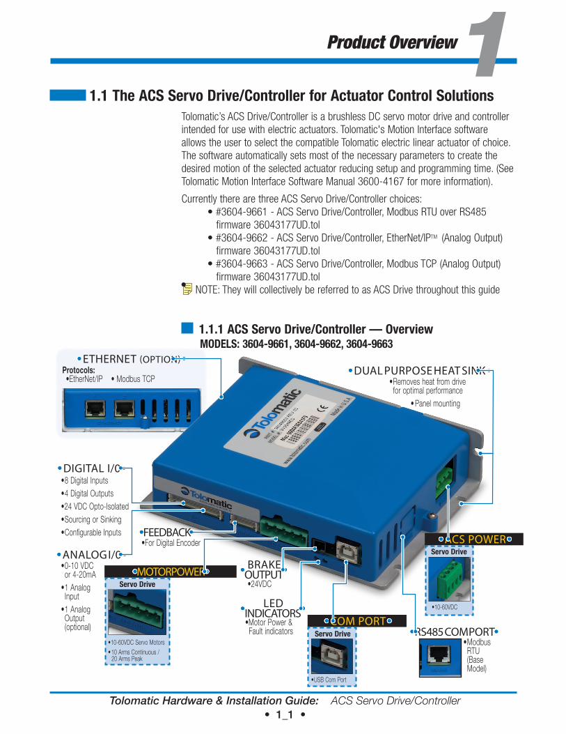
1.1.1 ACS Servo drive/Controller — overview
ModeLS: 3604-9661, 3604-9662, 3604-9663
MOTOR POWER
• 10-60VDC Servo Motors• 10 Arms Continuous /
20 Arms Peak
Servo drive
COM PORT
• USB Com Port
Servo drive
ACS POWER
• 10-60VDC
Servo drive
ETHERNET (OPTION)
DIGITAL I/0
ANALOG I/0 BRAKE
OUTPUT
LED INDICATORS
RS485 COM PORT
DUAL PURPOSE HEAT SINK
FEEDBACK
Protocols: • EtherNet/IP • Modbus TCP
• 8 Digital Inputs• 4 Digital Outputs•24 VDC Opto-Isolated• Sourcing or Sinking• Configurable Inputs
• 0-10 VDC or 4-20mA
• 1 Analog Input
• 1 Analog Output (optional)
• Modbus RTU (Base Model)
• Removes heat from drive for optimal performance
• Panel mounting
•Motor Power & Fault indicators
•24VDC
•For Digital Encoder
Tolomatic Hardware & Installation Guide: ACS Servo Drive/Controller • 1_2 •
1: P R O D U C T O V E R V I E W
ACS drive/Controller (3604-9661) Capabilities• 4, 8, or 16 move command modes (abso-
lute, force, incremental and jog or home• Zone output based on position
• Force limiting capability
• Configurable digital I/O (24 VDC Opto-Isolated) (sinking or sourcing)
• Compatible with most 24-48 VDC servo motors
• Brake output
• Analog position mode (0-10 VDC or 4-20 mA)
• Pneumatic mode replaces pneumatic valve logic for simple motion
• ModBus RTU over RS485 provides infinite positioning
• Adjustable motion profile parameters (velocity, accel/decel, force). Parameters are independently configurable for each move
ACS drive/Controller (3604-9662, 3604-9663) Additional Capabilities• EtherNet/IPTM mode provides infinite
positioning using EtherNet/IP and Modbus TCP protocols
• Dual EtherNet/IP port with internal switch for easy daisy chaining
• Analog output for Analog Position Mode
1.1.2 optional Accessories
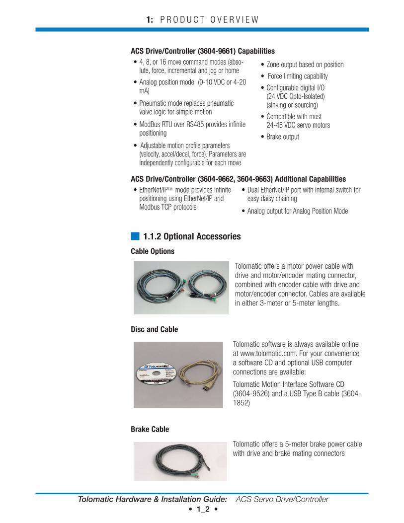
Cable options
Tolomatic offers a motor power cable with drive and motor/encoder mating connector, combined with encoder cable with drive and motor/encoder connector. Cables are available in either 3-meter or 5-meter lengths.
disc and Cable
Tolomatic software is always available online at www.tolomatic.com. For your convenience a software CD and optional USB computer connections are available:
Tolomatic Motion Interface Software CD (3604-9526) and a USB Type B cable (3604-1852)
Brake Cable
Tolomatic offers a 5-meter brake power cable with drive and brake mating connectors
Tolomatic Hardware & Installation Guide: ACS Servo Drive/Controller • 2_1 •
Environment, Dimensions & Mounting22.1 operating environment
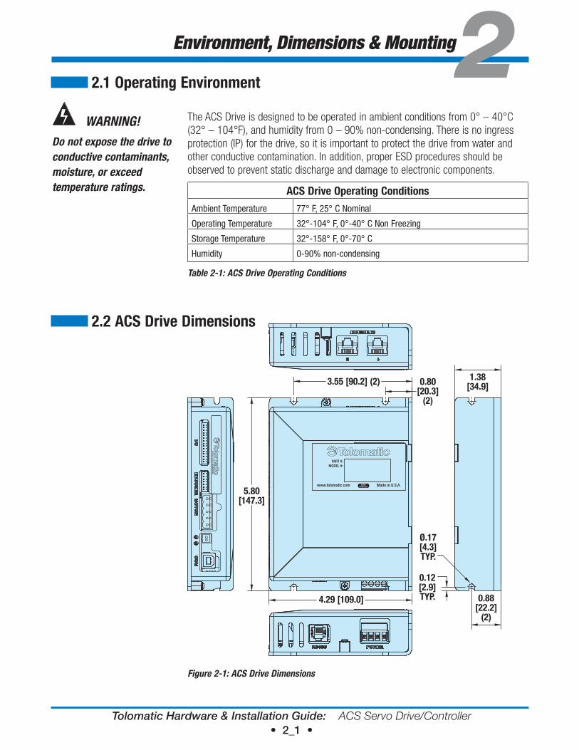
The ACS Drive is designed to be operated in ambient conditions from 0° – 40°C (32° – 104°F), and humidity from 0 – 90% non-condensing. There is no ingress protection (IP) for the drive, so it is important to protect the drive from water and other conductive contamination. In addition, proper ESD procedures should be observed to prevent static discharge and damage to electronic components.
ACS drive operating Conditions
Ambient Temperature 77° F, 25° C Nominal
Operating Temperature 32°-104° F, 0°-40° C Non Freezing
Storage Temperature 32°-158° F, 0°-70° C
Humidity 0-90% non-condensing
Table 2-1: ACS Drive Operating Conditions
3.55 [90.2] (2) 0.80[20.3]
(2)
5.80[147.3]
4.29 [109.0] 0.88[22.2]
(2)
0.12[2.9]TYP.
Ø.17[4.3]TYP.
1.38[34.9]
PART #:MODEL #:
www.tolomatic.com Made in U.S.A.RoHSCOMPLIANT
Figure 2-1: ACS Drive Dimensions
WARNING!
Do not expose the drive to conductive contaminants, moisture, or exceed temperature ratings.
2.2 ACS drive dimensions
Tolomatic Hardware & Installation Guide: ACS Servo Drive/Controller • 2_2 •
2: E N V I R O N M E N T, D I M E N S I O N S & M O U N T I N G
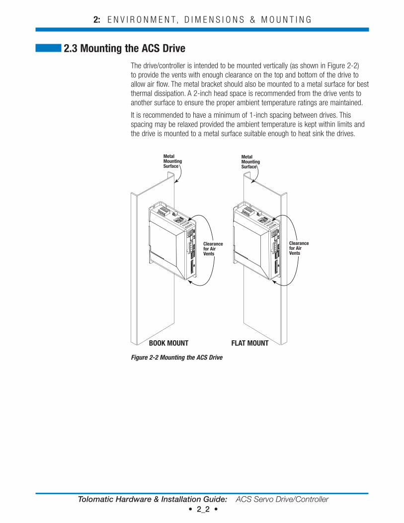
The drive/controller is intended to be mounted vertically (as shown in Figure 2-2) to provide the vents with enough clearance on the top and bottom of the drive to allow air flow. The metal bracket should also be mounted to a metal surface for best thermal dissipation. A 2-inch head space is recommended from the drive vents to another surface to ensure the proper ambient temperature ratings are maintained.
It is recommended to have a minimum of 1-inch spacing between drives. This spacing may be relaxed provided the ambient temperature is kept within limits and the drive is mounted to a metal surface suitable enough to heat sink the drives.
MetalMountingSurface
FLAT MOUNTBOOK MOUNT
Clearance for Air Vents
Clearance for Air Vents
Metal MountingSurface
Figure 2-2 Mounting the ACS Drive
2.3 Mounting the ACS drive
Tolomatic Hardware & Installation Guide: ACS Servo Drive/Controller • 3_1 •
CD & USB Cable33.1 Cd & USB Cable
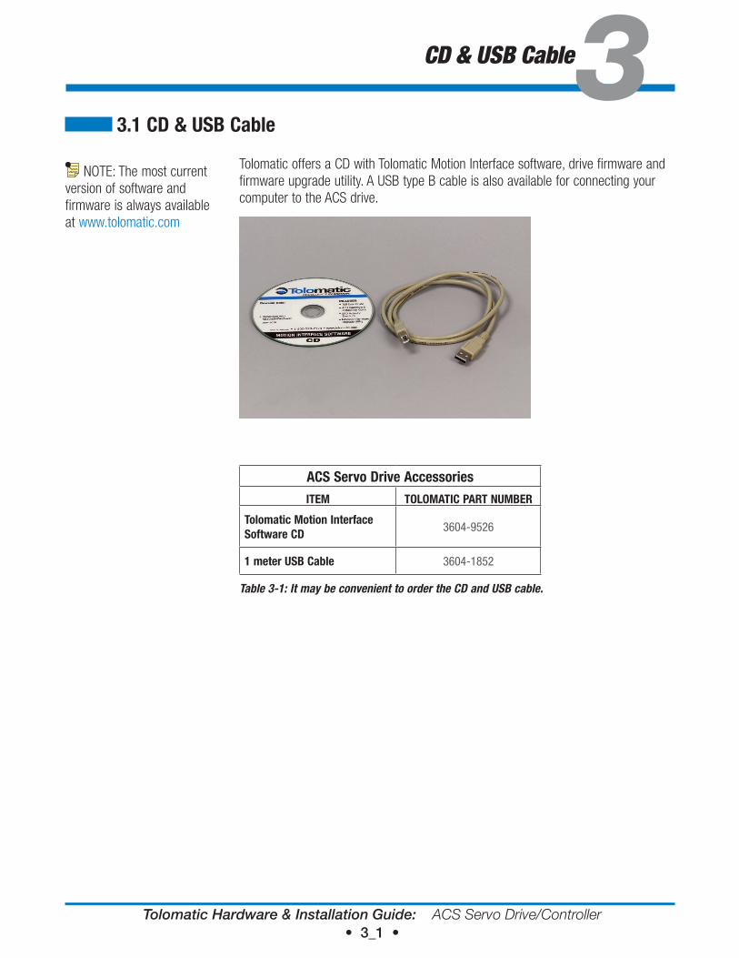
Tolomatic offers a CD with Tolomatic Motion Interface software, drive firmware and firmware upgrade utility. A USB type B cable is also available for connecting your computer to the ACS drive.
ACS Servo drive AccessoriesITeM ToLoMATIC PArT NUMBer
Tolomatic Motion Interface Software Cd
3604-9526
1 meter USB Cable 3604-1852
Table 3-1: It may be convenient to order the CD and USB cable.
NOTE: The most current version of software and firmware is always available at www.tolomatic.com
Tolomatic Hardware & Installation Guide: ACS Servo Drive/Controller • 4_1 •
4.1 ACS drive and Actuator Basic Setup
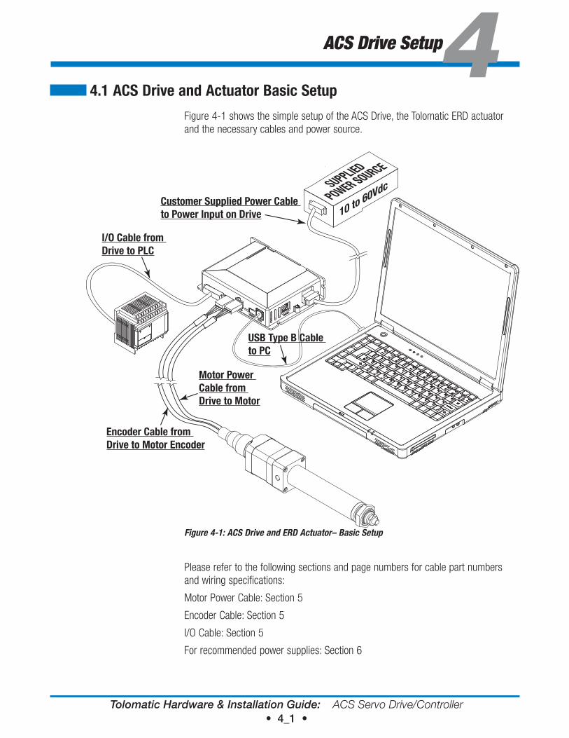
Figure 4-1 shows the simple setup of the ACS Drive, the Tolomatic ERD actuator and the necessary cables and power source.
Figure 4-1: ACS Drive and ERD Actuator– Basic Setup
Please refer to the following sections and page numbers for cable part numbers and wiring specifications:
Motor Power Cable: Section 5
Encoder Cable: Section 5
I/O Cable: Section 5
For recommended power supplies: Section 6
ACS Drive Setup4SUPPLIED
POWER SOURCE
10 to 60Vdc
USB Type B Cable to PC
Customer Supplied Power Cable to Power Input on Drive
I/O Cable from Drive to PLC
Encoder Cable from Drive to Motor Encoder
Motor Power Cable from Drive to Motor
Tolomatic Hardware & Installation Guide: ACS Servo Drive/Controller • 4_2 •
4: A C S D R I V E / C O N T R O L L E R S E T U P
4.1.1 Setup Procedures1. Install drive/controller and actuator into appropriate fixtures.
2. Wire the 10 to 60VDC power supply to the drive. See Section 6: Power Supply Selection.
3. Wire input and output signals to the desired logic device. See Section 5: Connections and Cables.
4. Attach motor and encoder cables.
5. Attach USB programming cable and install the Tolomatic Motion Interface software.
6. Configure ACS Drive.
7. Program the logic device.
Tolomatic Hardware & Installation Guide: ACS Servo Drive/Controller • 5_1 •
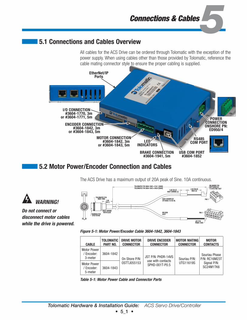
All cables for the ACS Drive can be ordered through Tolomatic with the exception of the power supply. When using cables other than those provided by Tolomatic, reference the cable mating connector style to ensure the proper cabling is supplied.
The ACS Drive has a maximum output of 20A peak of Sine. 10A continuous.
1.50[38.1]
HEAT SHRINKWITH GLUE
TOLOMATIC P/N 3604-1842 =118.1 [3000]TOLOMATIC P/N 3604-1843 =196.9 [5000] 2.00 [50.8]
MAX (2)1.00 [25.4]HEAT SHRINK (2)
PIN 1
PIN 1
ON SHORE P/NOSTTJO55153T-O-M 2190-1027
JST P/NPHDR-14VS
SOURIAU P/NUTG11619S
TOLOMATIC P/N3604-1909 IGUS CHAINFLEX
CF140US-15-03-UL
BELDEN8337
Figure 5-1: Motor Power/Encoder Cable 3604-1842, 3604-1843
CABLeToLoMATIC PArT No.
drIve MoTor CoNNeCTor
drIve eNCoder CoNNeCTor
MoTor MATING CoNNeCTor
MoTor CoNTACTS
Motor Power / Encoder: 3-meter
3604-1842On Shore P/N:OSTTJ055153
JST P/N: PHDR-14VS use with contacts SPHD-001T-P0.5
Souriau P/N: UTG11619S
Souriau Phase P/N: RC16M23T
Signal P/N: SC24M1TK6
Motor Power / Encoder: 5-meter
3604-1843
Table 5-1: Motor Power Cable and Connector Parts
Connections & Cables55.1 Connections and Cables overview
MoTor CoNNeCTIoN #3604-1842, 3m or #3604-1843, 5m
USB CoM PorT #3604-1852
BrAKe CoNNeCTIoN #3604-1941, 5m
eNCoder CoNNeCTIoN #3604-1842, 3m or #3604-1843, 5m
I/o CoNNeCTIoN #3604-1770, 3mor #3604-1771, 5m
rS485CoM PorT
PowerCoNNeCTIoNoNSHore PN:
ed950/4
etherNet/IPPorts
5.2 Motor Power/encoder Connection and Cables
WARNING!
Do not connect or disconnect motor cables while the drive is powered.
Led INdICATorS
Tolomatic Hardware & Installation Guide: ACS Servo Drive/Controller • 5_2 •
5: C O N N E C T I O N S & C A B L E S
1 2 3 4 5
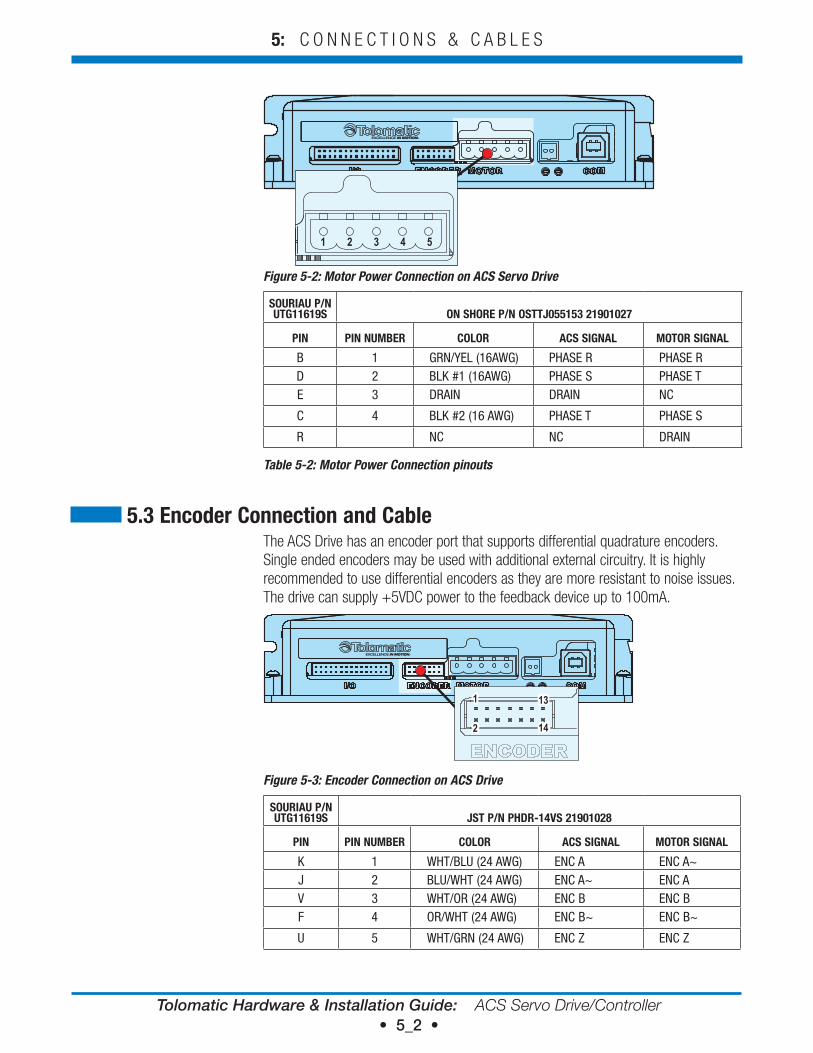
Figure 5-2: Motor Power Connection on ACS Servo Drive
SoUrIAU P/N UTG11619S oN SHore P/N oSTTJ055153 21901027
PIN PIN NUMBer CoLor ACS SIGNAL MoTor SIGNAL
B 1 GRN/YEL (16AWG) PHASE R PHASE RD 2 BLK #1 (16AWG) PHASE S PHASE TE 3 DRAIN DRAIN NC
C 4 BLK #2 (16 AWG) PHASE T PHASE S
R NC NC DRAIN
Table 5-2: Motor Power Connection pinouts
The ACS Drive has an encoder port that supports differential quadrature encoders. Single ended encoders may be used with additional external circuitry. It is highly recommended to use differential encoders as they are more resistant to noise issues. The drive can supply +5VDC power to the feedback device up to 100mA.
1
2 14
131
2 14
13
Figure 5-3: Encoder Connection on ACS Drive
SoUrIAU P/N UTG11619S JST P/N PHdr-14vS 21901028
PIN PIN NUMBer CoLor ACS SIGNAL MoTor SIGNAL
K 1 WHT/BLU (24 AWG) ENC A ENC A~J 2 BLU/WHT (24 AWG) ENC A~ ENC AV 3 WHT/OR (24 AWG) ENC B ENC BF 4 OR/WHT (24 AWG) ENC B~ ENC B~
U 5 WHT/GRN (24 AWG) ENC Z ENC Z
5.3 encoder Connection and Cable
Tolomatic Hardware & Installation Guide: ACS Servo Drive/Controller • 5_3 •
5: C O N N E C T I O N S & C A B L E S
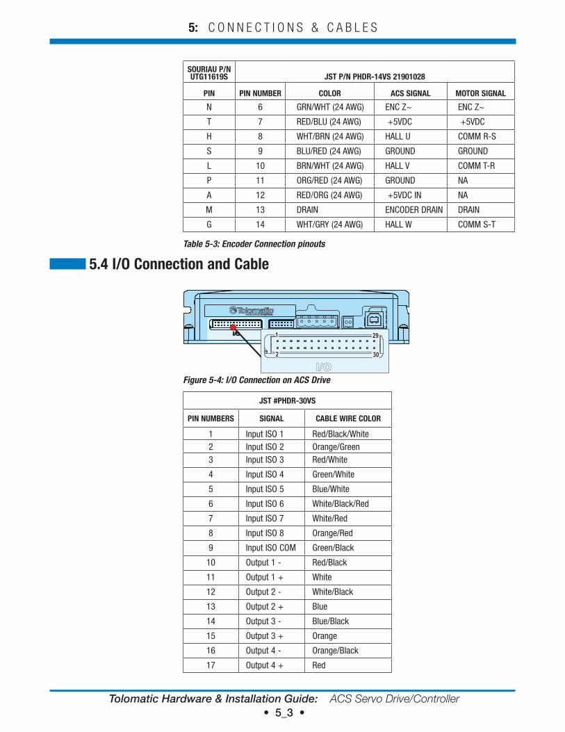
SoUrIAU P/N UTG11619S JST P/N PHdr-14vS 21901028
PIN PIN NUMBer CoLor ACS SIGNAL MoTor SIGNAL
N 6 GRN/WHT (24 AWG) ENC Z~ ENC Z~
T 7 RED/BLU (24 AWG) +5VDC +5VDC
H 8 WHT/BRN (24 AWG) HALL U COMM R-S
S 9 BLU/RED (24 AWG) GROUND GROUND
L 10 BRN/WHT (24 AWG) HALL V COMM T-R
P 11 ORG/RED (24 AWG) GROUND NA
A 12 RED/ORG (24 AWG) +5VDC IN NA
M 13 DRAIN ENCODER DRAIN DRAIN
G 14 WHT/GRY (24 AWG) HALL W COMM S-T
Table 5-3: Encoder Connection pinouts
1
2
29
30
1
2
29
30
Figure 5-4: I/O Connection on ACS Drive
JST #PHdr-30vS
PIN NUMBerS SIGNAL CABLe wIre CoLor
1 Input ISO 1 Red/Black/White2 Input ISO 2 Orange/Green3 Input ISO 3 Red/White
4 Input ISO 4 Green/White
5 Input ISO 5 Blue/White
6 Input ISO 6 White/Black/Red
7 Input ISO 7 White/Red
8 Input ISO 8 Orange/Red
9 Input ISO COM Green/Black
10 Output 1 - Red/Black
11 Output 1 + White
12 Output 2 - White/Black
13 Output 2 + Blue
14 Output 3 - Blue/Black
15 Output 3 + Orange
16 Output 4 - Orange/Black
17 Output 4 + Red
5.4 I/o Connection and Cable
Tolomatic Hardware & Installation Guide: ACS Servo Drive/Controller • 5_4 •
5: C O N N E C T I O N S & C A B L E S
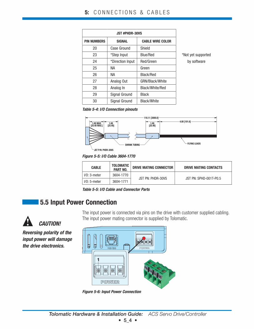
JST #PHdr-30vS
PIN NUMBerS SIGNAL CABLe wIre CoLor
20 Case Ground Shield
23 *Step Input Blue/Red *Not yet supported
24 *Direction Input Red/Green by software
25 NA Green
26 NA Black/Red
27 Analog Out GRN/Black/White
28 Analog In Black/White/Red
29 Signal Ground Black
30 Signal Ground Black/White
Table 5-4: I/O Connection pinouts
12345
JST P/N:PHDR-30VS
6
RED/BLK/WHT
9
7
1211
8
16
29
272423
13
17
1415
28
2620
2530
ORG/GRNRED/WHTGRN/WHTBLU/WHT
WHT/BLK/REDWHT/REDORG/REDGRN/BLK
WHT
WHT/BLKBLU
BLU/BLKORG
ORG/BLKRED
RED/BLKBLU/RED
10
RED/GRNGRN/BLK/WHTBLK/WHT/RED
BLKBLK/WHT
GRNBLK/RED
118.11 [3000.0]
JST P/N: PHDR-30VS
SHRINK TUBING FLYING LEADS
ALL CONDUCTORS ARE 20 AWGUSE OVERALL SHIELD WITH 20 AWG DRAIN WIRECONDUCTOR COLORS ARE UNIQUERoHS COMPLIANTMUST BE RATED 60°C OR BETTERCOLOR OF JACKET IS GRAY100V MIN WORKING VOLTAGECABLE TO BE TESTED FOR CONTINUITY AND SHORTSBAG INDIVIDUALLY
1.00 MAX.[25.40 MAX.]
4.00 [101.6]1.00
[25.40]1.00
[25.40]
Figure 5-5: I/O Cable 3604-1770
CABLe ToLoMATIC PArT No. drIve MATING CoNNeCTor drIve MATING CoNTACTS
I/O: 3-meter 3604-1770JST PN: PHDR-30VS JST PN: SPHD-001T-P0.5
I/O: 5-meter 3604-1771
Table 5-5: I/O Cable and Connector Parts
The input power is connected via pins on the drive with customer supplied cabling. The input power mating connector is supplied by Tolomatic.
1
Figure 5-6: Input Power Connection
5.5 Input Power Connection
CAUTION!
Reversing polarity of the input power will damage the drive electronics.
Tolomatic Hardware & Installation Guide: ACS Servo Drive/Controller • 5_5 •
5: C O N N E C T I O N S & C A B L E S
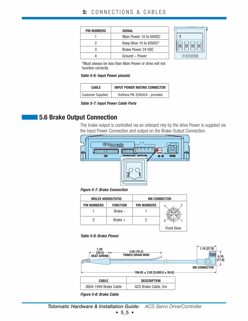
PIN NUMBerS SIGNAL
1 Main Power 10 to 60VDC
2 Keep Alive 10 to 60VDC*
3 Brake Power 24 VDC
4 Ground – Power
*Must always be less than Main Power or drive will not function correctly
Table 5-6: Input Power pinouts
CABLe INPUT Power MATING CoNNeCTor
Customer Supplied OnShore PN: ED950/4 - provided
Table 5-7: Input Power Cable Parts
The brake output is controlled via an onboard rely by the drive Power is supplied via the Input Power Connection and output on the Brake Output Connection.
12
Figure 5-7: Brake Connection
MoLeX #0050579702 M8 CoNNeCTor
PIN NUMBerS FUNCTIoN PIN NUMBerS
1 Brake - 1
2 Brake + 2
Front View
Table 5-8: Brake Pinout
3.00 [76.2]TINNED DRAIN WIRE
196.85 ± 2.00 [5,000.0 ± 50.6]
1.20 [30.5]
HEAT SHRINK
M8 CONNECTOR
0.70[17.8]
1.10 [27.9]
CABLe deSCrIPTIoN
3604-1949 Brake Cable ACS Brake Cable, 5m
Figure 5-8: Brake Cable
5.6 Brake output Connection
1
Tolomatic Hardware & Installation Guide: ACS Servo Drive/Controller • 5_6 •
5: C O N N E C T I O N S & C A B L E S
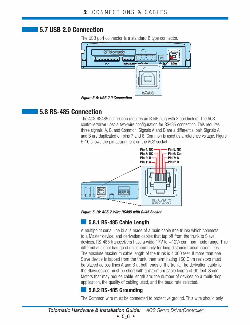
The USB port connector is a standard B type connector.
Figure 5-9: USB 2.0 Connection
The ACS RS485 connection requires an RJ45 plug with 3 conductors. The ACS controller/drive uses a two-wire configuration for RS485 connection. This requires three signals: A, B, and Common. Signals A and B are a differential pair. Signals A and B are duplicated on pins 7 and 8. Common is used as a reference voltage. Figure 5-10 shows the pin assignment on the ACS socket.
Pin 4: NCPin 3: NCPin 2: BPin 1: A
Pin 5: NCPin 6: ComPin 7: APin 8: B
Figure 5-10: ACS 2-Wire RS485 with RJ45 Socket
5.8.1 rS-485 Cable LengthA multipoint serial line bus is made of a main cable (the trunk) which connects to a Master device, and derivation cables that tap off from the trunk to Slave devices. RS-485 transceivers have a wide (-7V to +12V) common mode range. This differential signal has good noise immunity for long distance transmission lines. The absolute maximum cable length of the trunk is 4,000 feet. If more than one Slave device is tapped from the trunk, then terminating 150 Ohm resistors must be placed across lines A and B at both ends of the trunk. The derivation cable to the Slave device must be short with a maximum cable length of 60 feet. Some factors that may reduce cable length are: the number of devices on a multi-drop application, the quality of cabling used, and the baud rate selected.
5.8.2 rS-485 GroundingThe Common wire must be connected to protective ground. This wire should only
5.7 USB 2.0 Connection
5.8 rS-485 Connection
Tolomatic Hardware & Installation Guide: ACS Servo Drive/Controller • 5_7 •
5: C O N N E C T I O N S & C A B L E S
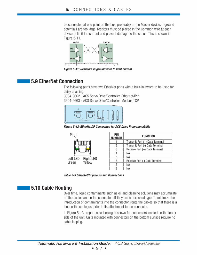
be connected at one point on the bus, preferably at the Master device. If ground potentials are too large, resistors must be placed in the Common wire at each device to limit the current and prevent damage to the circuit. This is shown in Figure 5-11.
+V +V
TXD
A
MASTER SLAVE #1
B
A
BRTS
RXD
TXDRTS
RXD
Figure 5-11: Resistors in ground wire to limit current
The following parts have two EtherNet ports with a built-in switch to be used for daisy chaining. 3604-9662 - ACS Servo Drive/Controller, EtherNet/IPTM 3604-9663 - ACS Servo Drive/Controller, Modbus TCP
Figure 5-12: EtherNet/IP Connection for ACS Drive Programmability
Pin 1
Left LEDGreen
Right LEDYellow
PIN NUMBer FUNCTIoN
1 Transmit Port (+) Data Terminal2 Transmit Port (-) Data Terminal3 Receive Port (+) Data Terminal4 NA5 NA6 Receive Port (-) Data Terminal7 NA8 NA
Table 5-9 EtherNet/IP pinouts and Connections
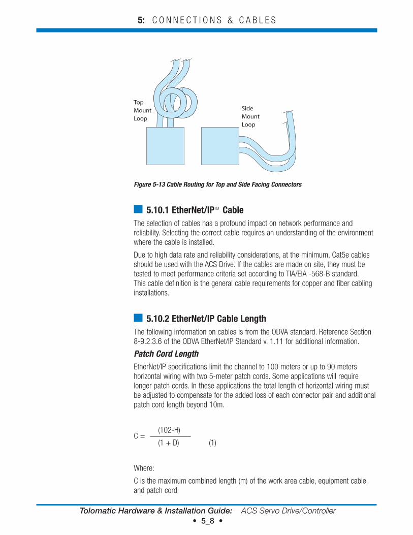
Over time, liquid contaminants such as oil and cleaning solutions may accumulate on the cables and in the connectors if they are an exposed type. To minimize the introduction of contaminants into the connector, route the cables so that there is a loop in the cable just prior to its attachment to the connector.
In Figure 5-13 proper cable looping is shown for connectors located on the top or side of the unit. Units mounted with connectors on the bottom surface require no cable looping.
5.10 Cable routing
5.9 etherNet Connection
Tolomatic Hardware & Installation Guide: ACS Servo Drive/Controller • 5_8 •
5: C O N N E C T I O N S & C A B L E S
Top Mount Loop
Side Mount Loop
Figure 5-13 Cable Routing for Top and Side Facing Connectors
5.10.1 etherNet/IPTM CableThe selection of cables has a profound impact on network performance and reliability. Selecting the correct cable requires an understanding of the environment where the cable is installed.
Due to high data rate and reliability considerations, at the minimum, Cat5e cables should be used with the ACS Drive. If the cables are made on site, they must be tested to meet performance criteria set according to TIA/EIA -568-B standard. This cable definition is the general cable requirements for copper and fiber cabling installations.
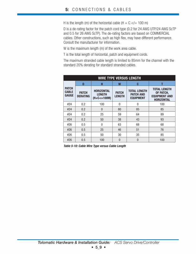
5.10.2 etherNet/IP Cable LengthThe following information on cables is from the ODVA standard. Reference Section 8-9.2.3.6 of the ODVA EtherNet/IP Standard v. 1.11 for additional information.
Patch Cord LengthEtherNet/IP specifications limit the channel to 100 meters or up to 90 meters horizontal wiring with two 5-meter patch cords. Some applications will require longer patch cords. In these applications the total length of horizontal wiring must be adjusted to compensate for the added loss of each connector pair and additional patch cord length beyond 10m.
(102-H)C =
(1 + D) (1)
Where:
C is the maximum combined length (m) of the work area cable, equipment cable, and patch cord
Tolomatic Hardware & Installation Guide: ACS Servo Drive/Controller • 5_9 •
5: C O N N E C T I O N S & C A B L E S
H is the length (m) of the horizontal cable (H + C </= 100 m)
D is a de-rating factor for the patch cord type (0.2 for 24 AWG UTP/24 AWG ScTP and 0.5 for 26 AWG ScTP). The de-rating factors are based on COMMERCIAL cables. Other constructions, such as high flex, may have different performance. Consult the manufacturer for information.
W is the maximum length (m) of the work area cable.
T is the total length of horizontal, patch and equipment cords.
The maximum stranded cable length is limited to 85mm for the channel with the standard 20% derating for standard stranded cables.
wIre TYPe verSUS LeNGTH
PATCH CABLe GAUGe
d H w C T
PATCH derATING
HorIZoNTAL LeNGTH
(H+C<=100M)
PATCH LeNGTH
ToTAL LeNGTH PATCH ANd eQUIPMeNT
ToTAL LeNGTH oF PATCH,
eQUIPMeNT ANd HorIZoNTAL
#24 0.2 100 0 0 100
#24 0.2 0 80 85 85
#24 0.2 25 59 64 89
#24 0.2 50 38 43 93
#26 0.5 0 63 68 68
#26 0.5 25 46 51 76
#26 0.5 50 30 35 85
#26 0.5 100 0 0 100
Table 5-10: Cable Wire Type versus Cable Length
Tolomatic Hardware & Installation Guide: ACS Servo Drive/Controller • 6_1 •
Specifications & Wiring6
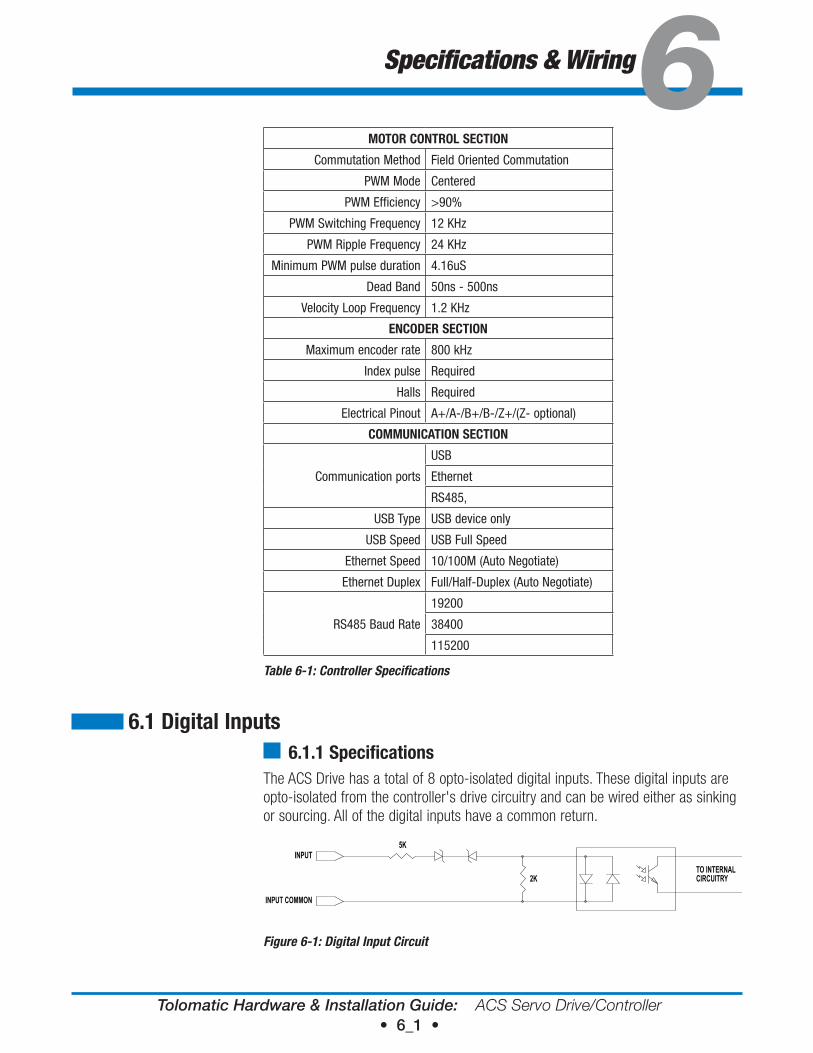
6.1 digital Inputs6.1.1 Specifications
The ACS Drive has a total of 8 opto-isolated digital inputs. These digital inputs are opto-isolated from the controller's drive circuitry and can be wired either as sinking or sourcing. All of the digital inputs have a common return.
5K
2K
INPUT
INPUT COMMON
TO INTERNALCIRCUITRY
INPUT CIRCUIT DIAGRAMFigure 6-1: Digital Input Circuit
MoTor CoNTroL SeCTIoN
Commutation Method Field Oriented Commutation
PWM Mode Centered
PWM Efficiency >90%
PWM Switching Frequency 12 KHz
PWM Ripple Frequency 24 KHz
Minimum PWM pulse duration 4.16uS
Dead Band 50ns - 500ns
Velocity Loop Frequency 1.2 KHz
eNCoder SeCTIoN
Maximum encoder rate 800 kHz
Index pulse Required
Halls Required
Electrical Pinout A+/A-/B+/B-/Z+/(Z- optional)
CoMMUNICATIoN SeCTIoN
Communication ports
USB
Ethernet
RS485,
USB Type USB device only
USB Speed USB Full Speed
Ethernet Speed 10/100M (Auto Negotiate)
Ethernet Duplex Full/Half-Duplex (Auto Negotiate)
RS485 Baud Rate
19200
38400
115200
Table 6-1: Controller Specifications
Tolomatic Hardware & Installation Guide: ACS Servo Drive/Controller • 6_2 •
6: S P E C I F I C A T I O N S & W I R I N G
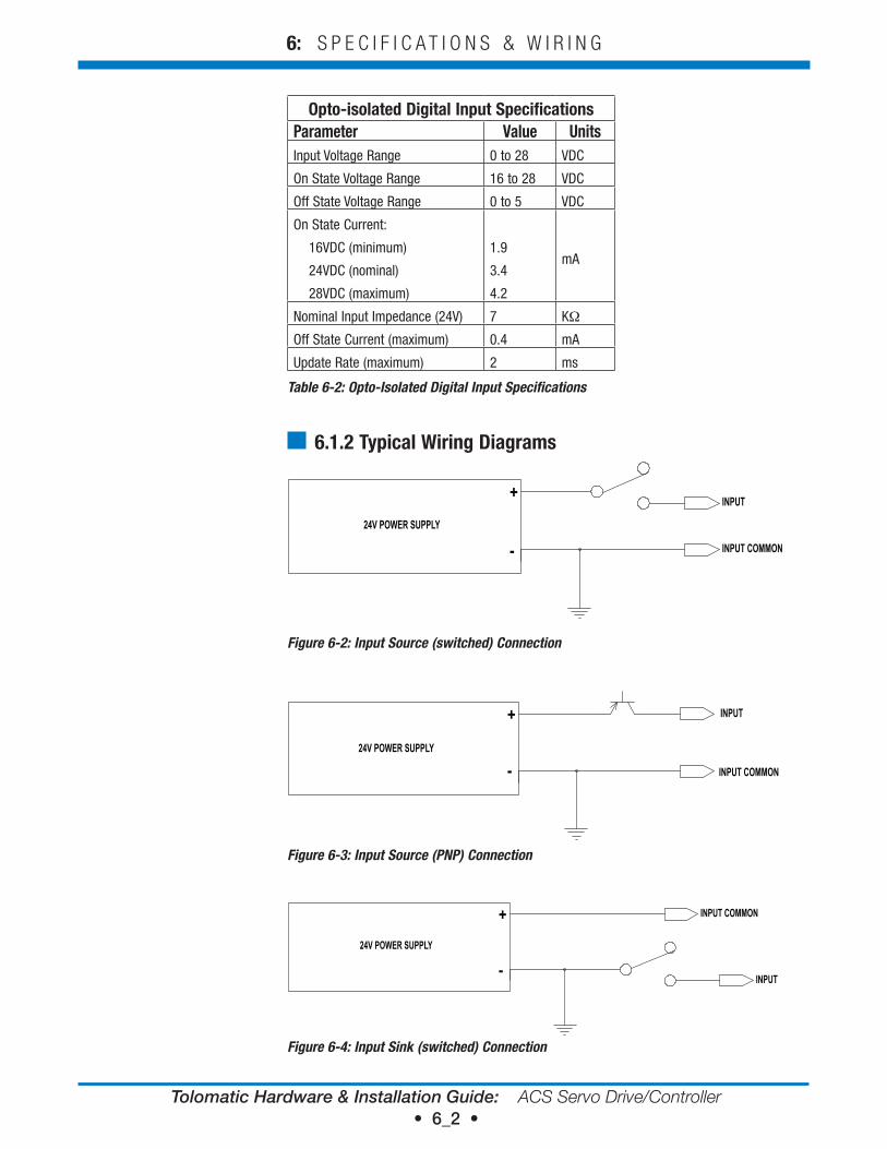
opto-isolated digital Input SpecificationsParameter value UnitsInput Voltage Range 0 to 28 VDC
On State Voltage Range 16 to 28 VDC
Off State Voltage Range 0 to 5 VDC
On State Current:
16VDC (minimum)
24VDC (nominal)
28VDC (maximum)
1.9
3.4
4.2
mA
Nominal Input Impedance (24V) 7 KΩ
Off State Current (maximum) 0.4 mA
Update Rate (maximum) 2 ms
Table 6-2: Opto-Isolated Digital Input Specifications
6.1.2 Typical wiring diagrams
INPUT
INPUT COMMON
INPUT SOURCED (SWITCHED) CONNECTION
24V POWER SUPPLY
+
-
Figure 6-2: Input Source (switched) Connection
INPUT
INPUT COMMON
24V POWER SUPPLY
INPUT SOURCED (PNP) CONNECTION
+
-
Figure 6-3: Input Source (PNP) Connection
INPUT
INPUT COMMON
INPUT SINK (SWITCHED) CONNECTION
24V POWER SUPPLY
+
-
Figure 6-4: Input Sink (switched) Connection
Tolomatic Hardware & Installation Guide: ACS Servo Drive/Controller • 6_3 •
6: S P E C I F I C A T I O N S & W I R I N G
INPUT
INPUT COMMON
INPUT SINK (NPN) CONNECTION
24V POWER SUPPLY
+
-
Figure 6-5: Input Sink (NPN) Connection
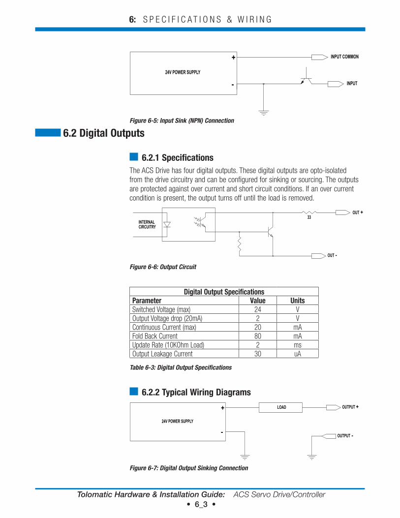
6.2.1 SpecificationsThe ACS Drive has four digital outputs. These digital outputs are opto-isolated from the drive circuitry and can be configured for sinking or sourcing. The outputs are protected against over current and short circuit conditions. If an over current condition is present, the output turns off until the load is removed.
33OUT +
OUT -
INTERNALCIRCUITRY
OUTPUT CIRCUIT
Figure 6-6: Output Circuit
digital output SpecificationsParameter value UnitsSwitched Voltage (max) 24 VOutput Voltage drop (20mA) 2 VContinuous Current (max) 20 mAFold Back Current 80 mAUpdate Rate (10KOhm Load) 2 msOutput Leakage Current 30 uA
Table 6-3: Digital Output Specifications
6.2.2 Typical wiring diagramsOUTPUT +
OUTPUT -
24V POWER SUPPLY
DIGITAL OUTPUT SINKING WIRING DIAGRAM
LOAD+
-
Figure 6-7: Digital Output Sinking Connection
6.2 digital outputs
Tolomatic Hardware & Installation Guide: ACS Servo Drive/Controller • 6_4 •
6: S P E C I F I C A T I O N S & W I R I N G
6.3 Analog Input
OUTPUT +OUTPUT -24V POWER SUPPLY
DIGITAL OUTPUT SOURCING WIRING DIAGRAM
LOAD
+
-
Figure 6-8: Digital Output Sourcing Connection
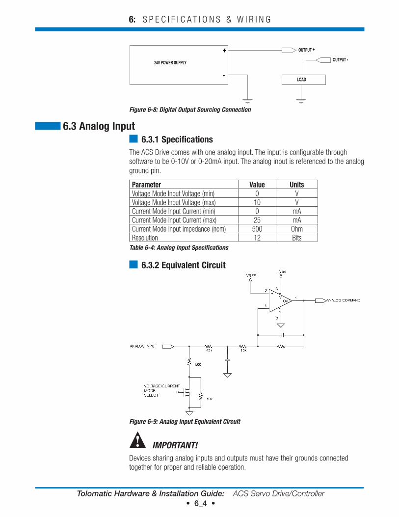
6.3.1 SpecificationsThe ACS Drive comes with one analog input. The input is configurable through software to be 0-10V or 0-20mA input. The analog input is referenced to the analog ground pin.
Parameter value UnitsVoltage Mode Input Voltage (min) 0 VVoltage Mode Input Voltage (max) 10 VCurrent Mode Input Current (min) 0 mACurrent Mode Input Current (max) 25 mACurrent Mode Input impedance (nom) 500 OhmResolution 12 Bits
Table 6-4: Analog Input Specifications
6.3.2 equivalent Circuit
Figure 6-9: Analog Input Equivalent Circuit
IMPORTANT!Devices sharing analog inputs and outputs must have their grounds connected together for proper and reliable operation.
Tolomatic Hardware & Installation Guide: ACS Servo Drive/Controller • 6_5 •
6: S P E C I F I C A T I O N S & W I R I N G
6.4 Analog output6.4.1 Specifications
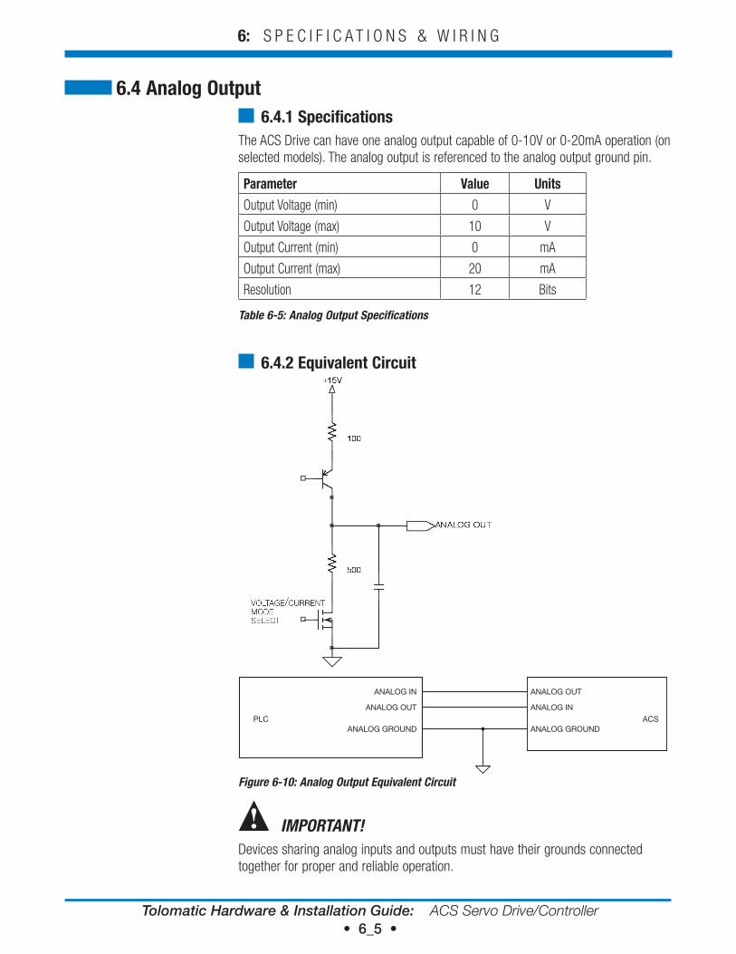
The ACS Drive can have one analog output capable of 0-10V or 0-20mA operation (on selected models). The analog output is referenced to the analog output ground pin.
Parameter value UnitsOutput Voltage (min) 0 V
Output Voltage (max) 10 V
Output Current (min) 0 mA
Output Current (max) 20 mA
Resolution 12 Bits
Table 6-5: Analog Output Specifications
6.4.2 equivalent Circuit
PLC ACS
ANALOG OUT
ANALOG IN
ANALOG GROUND
ANALOG IN
ANALOG OUT
ANALOG GROUND
Figure 6-10: Analog Output Equivalent Circuit
IMPORTANT!Devices sharing analog inputs and outputs must have their grounds connected together for proper and reliable operation.
Tolomatic Hardware & Installation Guide: ACS Servo Drive/Controller • 6_6 •
6: S P E C I F I C A T I O N S & W I R I N G
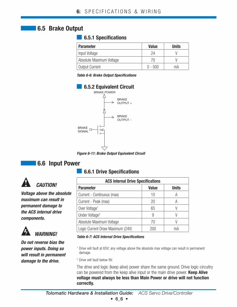
6.5 Brake output 6.5.1 Specifications
Parameter value UnitsInput Voltage 24 V
Absolute Maximum Voltage 70 V
Output Current 0 - 500 mA
Table 6-6: Brake Output Specifications
6.5.2 equivalent CircuitBRAKE POWER
BRAKEOUTPUT +
BRAKEOUTPUT -
BRAKESIGNAL
Figure 6-11: Brake Output Equivalent Circuit
6.6.1 drive Specifications
ACS Internal drive SpecificationsParameter value UnitsCurrent - Continuous (max) 10 A
Current - Peak (max) 20 A
Over Voltage1 65 V
Under Voltage2 9 V
Absolute Maximum Voltage 70 V
Logic Current Draw Maximum (24V) 200 mA
Table 6-7: ACS Internal Drive Specifications
1 Drive will fault at 65V; any voltage above the absolute max voltage can result in permanent damage.
2 Drive will fault below 9V.
The drive and logic (keep alive) power share the same ground. Drive logic circuitry can be powered from the keep alive input or the main drive power. Keep Alive voltage must always be less than Main Power or drive will not function correctly.
6.6 Input Power
CAUTION!
Voltage above the absolute maximum can result in permanent damage to the ACS internal drive components.
WARNING!
Do not reverse bias the power inputs. Doing so will result in permanent damage to the drive.
Tolomatic Hardware & Installation Guide: ACS Servo Drive/Controller • 6_7 •
6: S P E C I F I C A T I O N S & W I R I N G
WARNING!
Do not short circuit the motor power at the power connector. Doing so may damage the drive power electronics. The motor/cable is part of the current regulation circuitry. For a short occurring in a motor, the motor leads should provide enough resistance and inductance to prevent dangerous peak currents from occurring.
6.6.2 Power Supply Sizing GuidelinesBoth unregulated and regulated power supply can be used to power the ACS Drive.
Unregulated supply can be a better choice depending on the application as they have a larger output capacitance. This characteristic makes an unregulated power supply a better energy absorption source. Unregulated power supply is a good choice for applications that require aggressive acceleration it can provide peak currents without faulting and will not trip on high voltage. However, unregulated power supply does not have over voltage protection and care must be taken not to exceed the maximum voltage of the actuator by using a shunt regulator and proper fusing to prevent excessive loading of the supply.
regulated supply can be used to power the ACS drive, but additional measures may need to be taken. To prevent regenerative energy from reaching the supply, a blocking diode and capacitor, appropriately sized for the application, should be installed. In addition, a shunt regulator may be needed to dissipate excess energy. A shunt regulator is available Part Number 2180-1163.
The ACS Drive is intended to run off of an isolated DC power source. The power supply required will depend on the application. A 48V supply will allow the actuator to operate at maximum speed. A 24V supply will result in approximately half the rated velocity. Input current will depend on the actuator power needed in the installation. If operating more than one actuator on the same power supply, add the required power supply rating for each actuator.
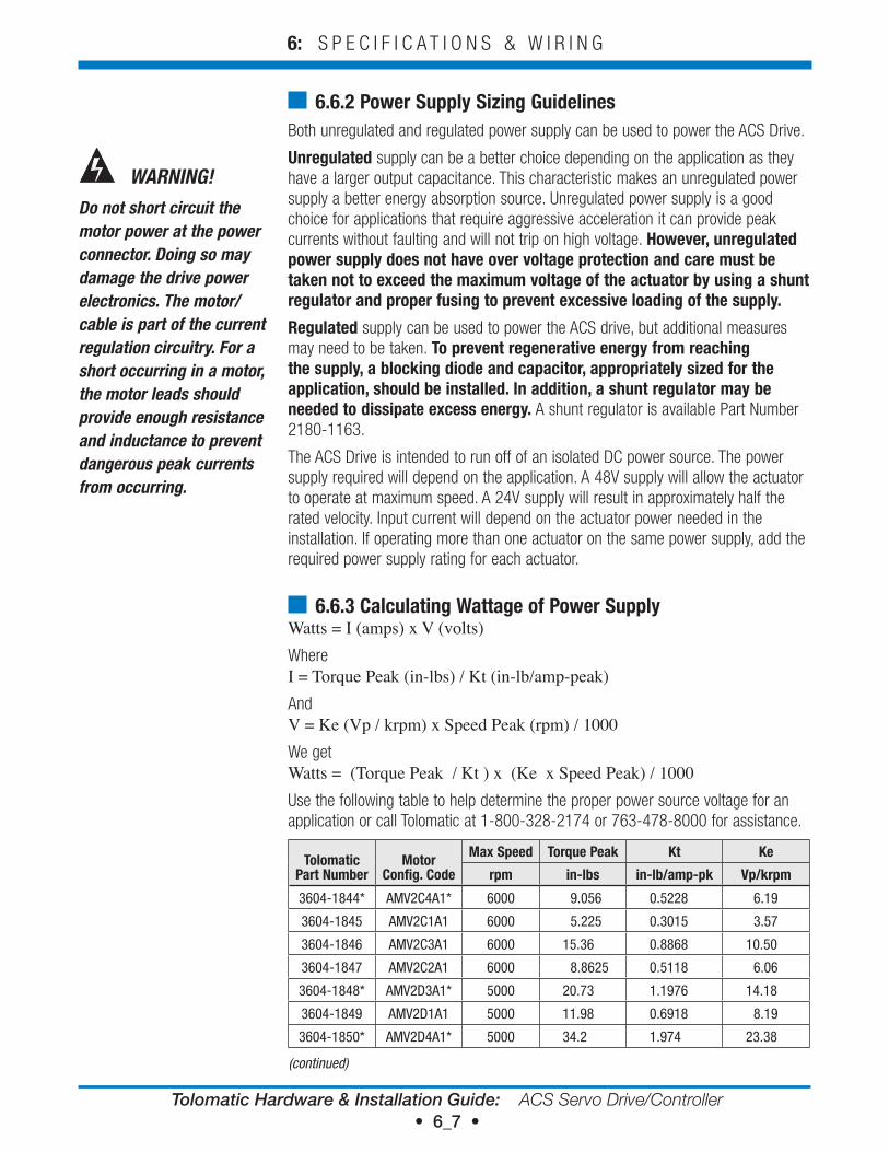
6.6.3 Calculating wattage of Power SupplyWatts = I (amps) x V (volts)WhereI = Torque Peak (in-lbs) / Kt (in-lb/amp-peak)AndV = Ke (Vp / krpm) x Speed Peak (rpm) / 1000We getWatts = (Torque Peak / Kt ) x (Ke x Speed Peak) / 1000Use the following table to help determine the proper power source voltage for an application or call Tolomatic at 1-800-328-2174 or 763-478-8000 for assistance.
Tolomatic Part Number
Motor Config. Code
Max Speed Torque Peak Kt Ke
rpm in-lbs in-lb/amp-pk vp/krpm
3604-1844* AMV2C4A1* 6000 9.056 0.5228 6.19
3604-1845 AMV2C1A1 6000 5.225 0.3015 3.57
3604-1846 AMV2C3A1 6000 15.36 0.8868 10.50
3604-1847 AMV2C2A1 6000 8.8625 0.5118 6.06
3604-1848* AMV2D3A1* 5000 20.73 1.1976 14.18
3604-1849 AMV2D1A1 5000 11.98 0.6918 8.19
3604-1850* AMV2D4A1* 5000 34.2 1.974 23.38
(continued)
Tolomatic Hardware & Installation Guide: ACS Servo Drive/Controller • 6_8 •
6: S P E C I F I C A T I O N S & W I R I N G
Tolomatic Part Number
Motor Config. Code
Max Speed Torque Peak Kt Ke
rpm in-lbs in-lb/amp-pk vp/krpm
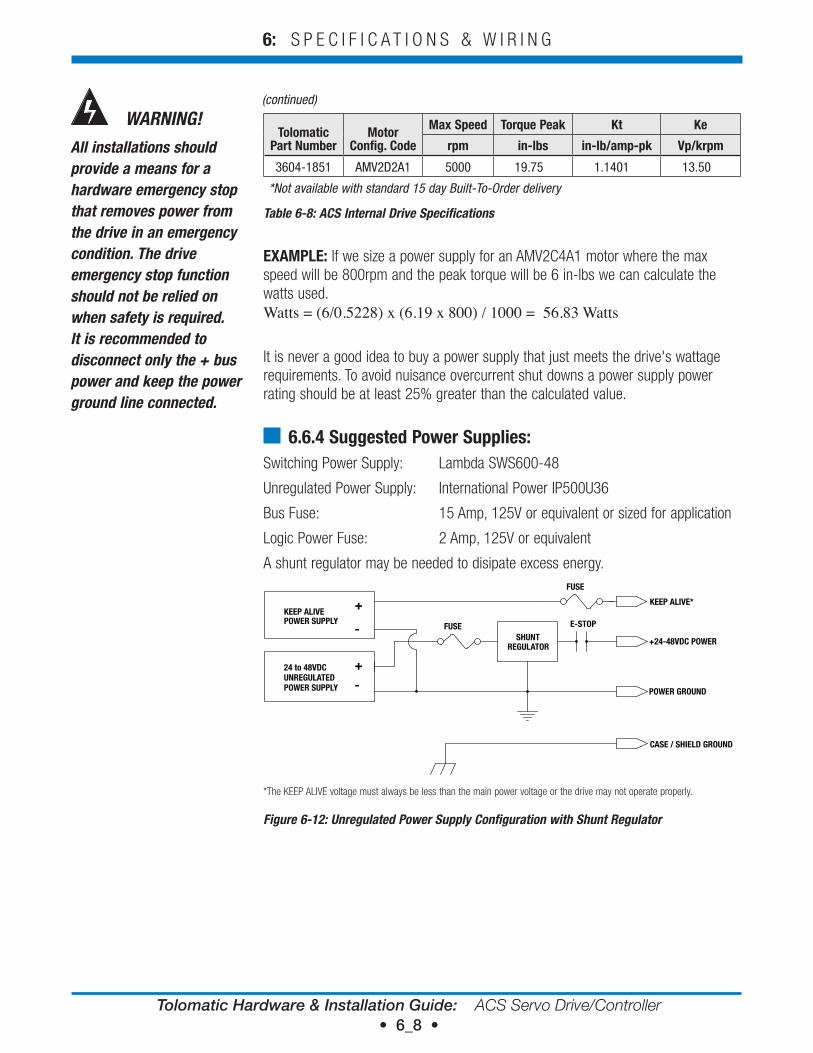
3604-1851 AMV2D2A1 5000 19.75 1.1401 13.50
*Not available with standard 15 day Built-To-Order delivery
Table 6-8: ACS Internal Drive Specifications
eXAMPLe: If we size a power supply for an AMV2C4A1 motor where the max speed will be 800rpm and the peak torque will be 6 in-lbs we can calculate the watts used. Watts = (6/0.5228) x (6.19 x 800) / 1000 = 56.83 Watts
It is never a good idea to buy a power supply that just meets the drive's wattage requirements. To avoid nuisance overcurrent shut downs a power supply power rating should be at least 25% greater than the calculated value.
6.6.4 Suggested Power Supplies:Switching Power Supply: Lambda SWS600-48
Unregulated Power Supply: International Power IP500U36
Bus Fuse: 15 Amp, 125V or equivalent or sized for application
Logic Power Fuse: 2 Amp, 125V or equivalent
A shunt regulator may be needed to disipate excess energy.
+24-48VDC POWER
POWER GROUND
CASE / SHIELD GROUND
UNREGULATEDPOWER SUPPLY
24 to 48VDC
SHUNTREGULATOR
FUSE E-STOP
+
-
KEEP ALIVE*
POWER SUPPLYKEEP ALIVE
+
-
FUSE
*The KEEP ALIVE voltage must always be less than the main power voltage or the drive may not operate properly.
Figure 6-12: Unregulated Power Supply Configuration with Shunt Regulator
WARNING!
All installations should provide a means for a hardware emergency stop that removes power from the drive in an emergency condition. The drive emergency stop function should not be relied on when safety is required. It is recommended to disconnect only the + bus power and keep the power ground line connected.
(continued)
Tolomatic Hardware & Installation Guide: ACS Servo Drive/Controller • 6_9 •
6: S P E C I F I C A T I O N S & W I R I N G
+24-48VDC POWER
POWER GROUND
CASE / SHIELD GROUND
REGULATEDPOWER SUPPLY
24 to 48VDC+
-
DIODE
CAPACITOR
FUSE E-STOP
KEEP ALIVE*
POWER SUPPLYKEEP ALIVE
+
-
FUSE
*The KEEP ALIVE voltage must always be less than the main power voltage or the drive may not operate properly.
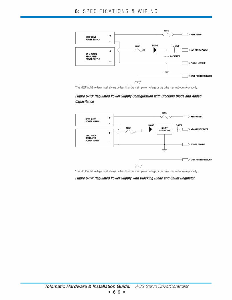
Figure 6-13: Regulated Power Supply Configuration with Blocking Diode and Added Capacitance
+24-48VDC POWER
POWER GROUND
CASE / SHIELD GROUND
KEEP ALIVE*
REGULATEDPOWER SUPPLY
24 to 48VDC+
-
POWER SUPPLYKEEP ALIVE
+
-DIODE
FUSEE-STOP
FUSE
SHUNTREGULATOR
*The KEEP ALIVE voltage must always be less than the main power voltage or the drive may not operate properly.
Figure 6-14: Regulated Power Supply with Blocking Diode and Shunt Regulator
Tolomatic Hardware & Installation Guide: ACS Servo Drive/Controller • 7_1 •
I/O Timing Diagrams77.1 I/o Timing diagrams
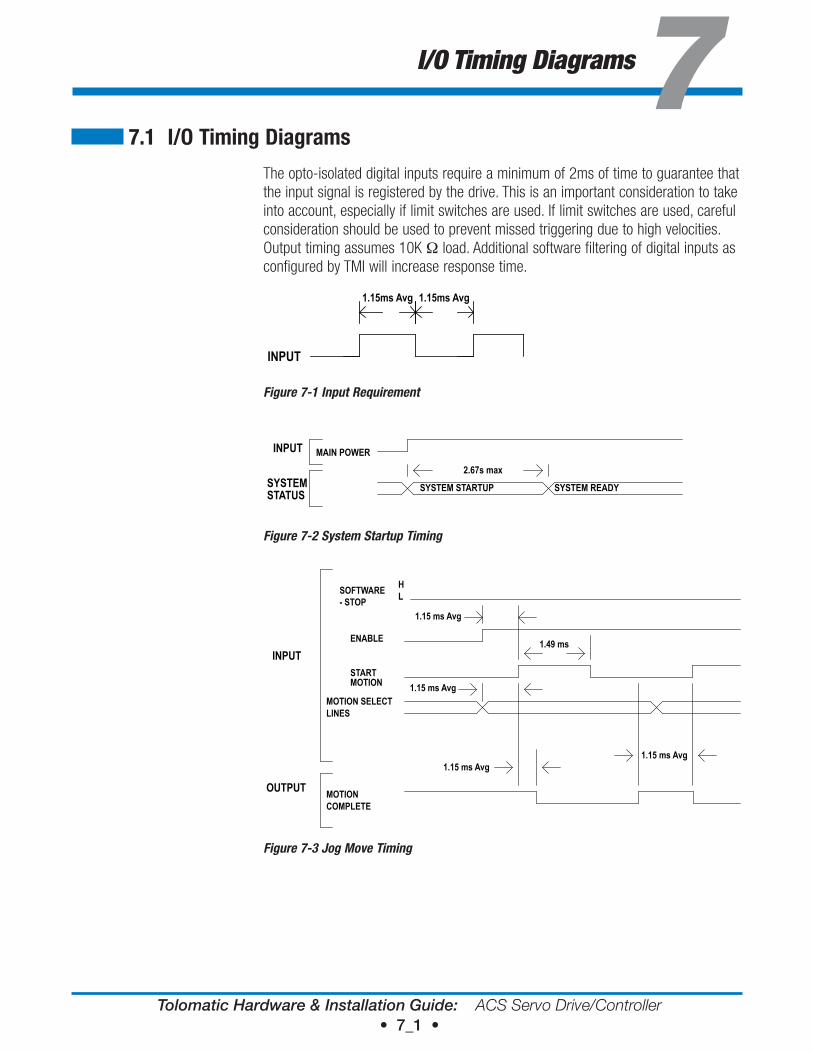
The opto-isolated digital inputs require a minimum of 2ms of time to guarantee that the input signal is registered by the drive. This is an important consideration to take into account, especially if limit switches are used. If limit switches are used, careful consideration should be used to prevent missed triggering due to high velocities. Output timing assumes 10K Ω load. Additional software filtering of digital inputs as configured by TMI will increase response time.
INPUT
1.15ms Avg 1.15ms Avg
INPUT REQUIREMENTFigure 7-1 Input Requirement
INPUT MAIN POWER
SYSTEMSTATUS SYSTEM STARTUP SYSTEM READY
2.67s max
SYSTEM STARTUP TIMING
Figure 7-2 System Startup Timing
INPUT
SOFTWARE- STOP
ENABLE
HL
1.49 ms
STARTMOTION
MOTION SELECTLINES
MOTIONCOMPLETE
OUTPUT
JOG TIMING
1.15 ms Avg
1.15 ms Avg
1.15 ms Avg1.15 ms Avg
Figure 7-3 Jog Move Timing
Tolomatic Hardware & Installation Guide: ACS Servo Drive/Controller • 7_2 •
7: I / O T I M I N G D I A G R A M S
INPUT
H
L
ENABLE
STARTMOTION
1.15 ms Avg
1.15 ms Avg 1.15 ms Avg
1.15 ms Avg1.15 ms Avg
1.15 ms Avg
MOTION SELECTLINES
OUTPUTMOTION COMPLETE
START MOTION TIMING
SOFTWARE- STOP
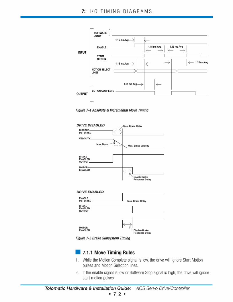
Figure 7-4 Absolute & Incremental Move Timing
DISABLEDETECTED
VELOCITY
BRAKEENABLEDOUTPUT
MOTORENABLED
ENABLEDETECTED
BRAKEENABLEDOUTPUT
MOTORENABLED
DRIVE DISABLED
DRIVE ENABLED
Max. Brake Delay
Max. Decel. Max. Brake Velocity
Enable Brake Response Delay
Max. Brake Delay
Disable Brake Response Delay
Figure 7-5 Brake Subsystem Timing
7.1.1 Move Timing rules1. While the Motion Complete signal is low, the drive will ignore Start Motion
pulses and Motion Selection lines.
2. If the enable signal is low or Software Stop signal is high, the drive will ignore start motion pulses.
Tolomatic Hardware & Installation Guide: ACS Servo Drive/Controller • 8_1 •
Move Select Logic88.1 Move Select Logic Table
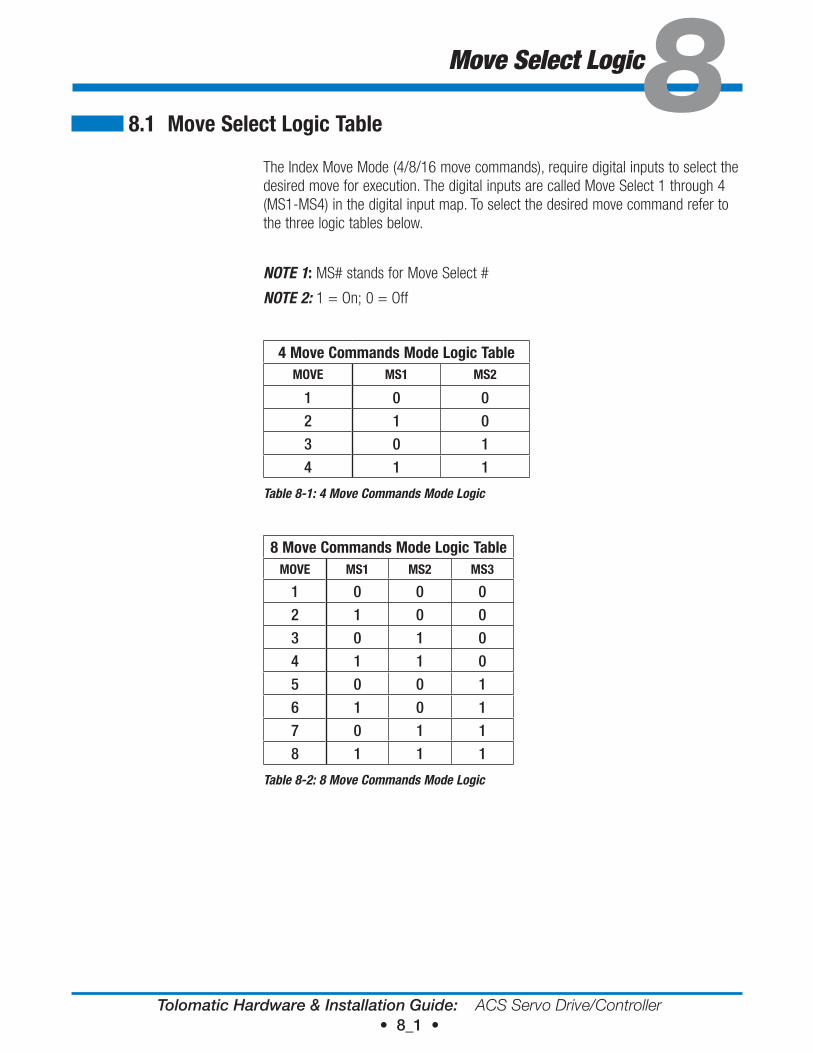
The Index Move Mode (4/8/16 move commands), require digital inputs to select the desired move for execution. The digital inputs are called Move Select 1 through 4 (MS1-MS4) in the digital input map. To select the desired move command refer to the three logic tables below.
NOTE 1: MS# stands for Move Select #
NOTE 2: 1 = On; 0 = Off
4 Move Commands Mode Logic TableMove MS1 MS2
1 0 02 1 03 0 14 1 1
Table 8-1: 4 Move Commands Mode Logic
8 Move Commands Mode Logic TableMove MS1 MS2 MS3
1 0 0 02 1 0 03 0 1 04 1 1 05 0 0 16 1 0 17 0 1 18 1 1 1
Table 8-2: 8 Move Commands Mode Logic
Tolomatic Hardware & Installation Guide: ACS Servo Drive/Controller • 8_2 •
8: M O V E S E L E C T L O G I C
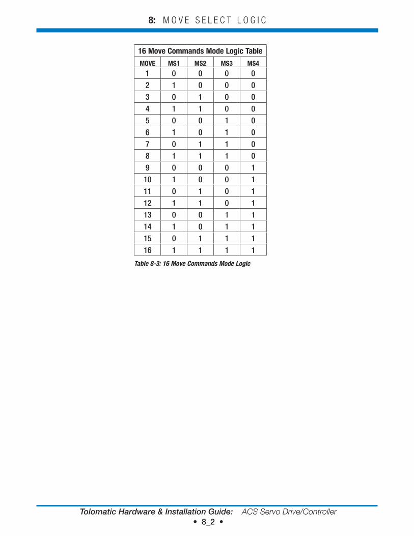
16 Move Commands Mode Logic TableMove MS1 MS2 MS3 MS4
1 0 0 0 02 1 0 0 03 0 1 0 04 1 1 0 05 0 0 1 06 1 0 1 07 0 1 1 08 1 1 1 09 0 0 0 110 1 0 0 111 0 1 0 112 1 1 0 113 0 0 1 114 1 0 1 115 0 1 1 116 1 1 1 1
Table 8-3: 16 Move Commands Mode Logic
Tolomatic Hardware & Installation Guide: ACS Servo Drive/Controller • 9_1 •
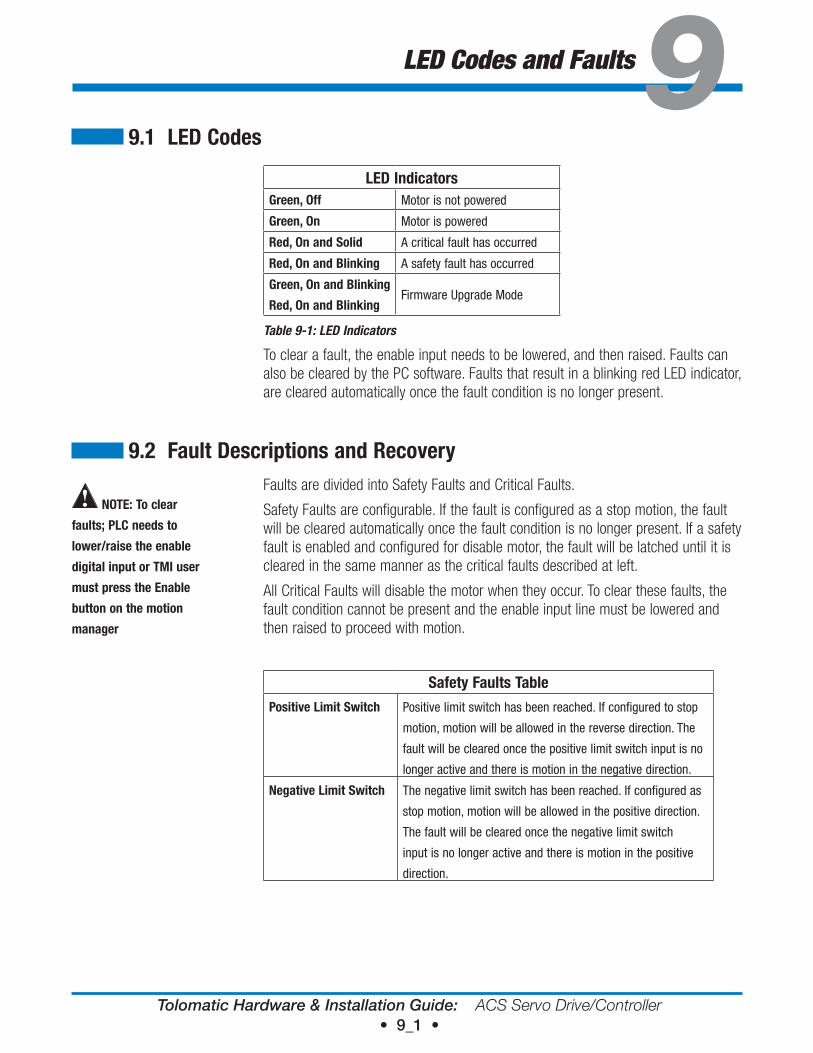
LED Codes and Faults99.1 Led Codes
Led IndicatorsGreen, off Motor is not powered
Green, on Motor is powered
red, on and Solid A critical fault has occurred
red, on and Blinking A safety fault has occurred
Green, on and Blinking
red, on and BlinkingFirmware Upgrade Mode
Table 9-1: LED Indicators
To clear a fault, the enable input needs to be lowered, and then raised. Faults can also be cleared by the PC software. Faults that result in a blinking red LED indicator, are cleared automatically once the fault condition is no longer present.
9.2 Fault descriptions and recoveryFaults are divided into Safety Faults and Critical Faults.
Safety Faults are configurable. If the fault is configured as a stop motion, the fault will be cleared automatically once the fault condition is no longer present. If a safety fault is enabled and configured for disable motor, the fault will be latched until it is cleared in the same manner as the critical faults described at left.
All Critical Faults will disable the motor when they occur. To clear these faults, the fault condition cannot be present and the enable input line must be lowered and then raised to proceed with motion.
Safety Faults TablePositive Limit Switch Positive limit switch has been reached. If configured to stop
motion, motion will be allowed in the reverse direction. The
fault will be cleared once the positive limit switch input is no
longer active and there is motion in the negative direction.
Negative Limit Switch The negative limit switch has been reached. If configured as
stop motion, motion will be allowed in the positive direction.
The fault will be cleared once the negative limit switch
input is no longer active and there is motion in the positive
direction.
NoTe: To clear
faults; PLC needs to
lower/raise the enable
digital input or TMI user
must press the enable
button on the motion
manager
Tolomatic Hardware & Installation Guide: ACS Servo Drive/Controller • 9_2 •
9 : L E D I N D I C A T O R S A N D F A U L T S
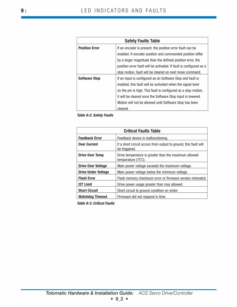
Safety Faults TablePosition error If an encoder is present, the position error fault can be
enabled. If encoder position and commanded position differ
by a larger magnitude than the defined position error, the
position error fault will be activated. If fault is configured as a
stop motion, fault will be cleared on next move command.
Software Stop If an input is configured as an Software Stop and fault is
enabled, this fault will be activated when the signal level
on the pin is high. This fault is configured as a stop motion,
it will be cleared once the Software Stop input is lowered.
Motion will not be allowed until Software Stop has been
cleared.
Table 9-2: Safety Faults
Critical Faults TableFeedback error Feedback device is malfunctioning.
over Current If a short circuit occurs from output to ground, this fault will be triggered.
drive over Temp Drive temperature is greater than the maximum allowed temperature (75˚C).
drive over voltage Main power voltage exceeds the maximum voltage.
drive Under voltage Main power voltage below the minimum voltage.
Flash error Flash memory checksum error or firmware version mismatch
I2T Limit Drive power usage greater than max allowed
Short Circuit Short circuit to ground condition on motor
watchdog Timeout Firmware did not respond in time
Table 9-3: Critical Faults
Tolomatic Hardware & Installation Guide: ACS Servo Drive/Controller • 10_1 •
Troubleshooting1010.1 Troubleshooting
10.1.1 Troubleshooting the ACS Servo drive
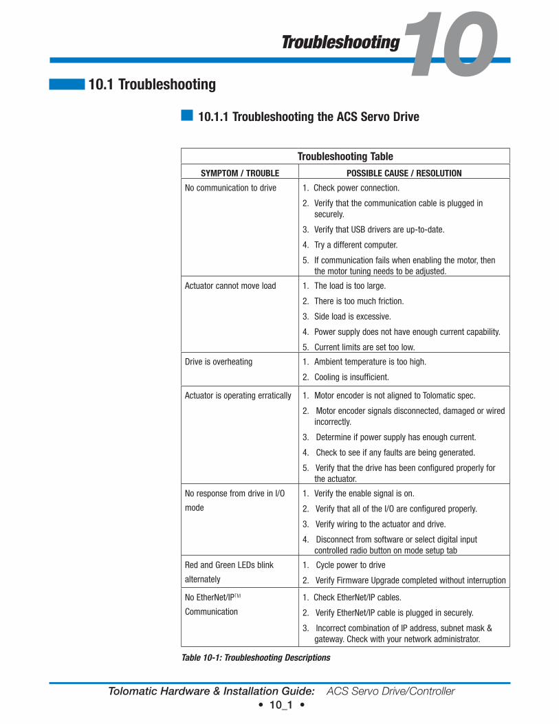
Troubleshooting TableSYMPToM / TroUBLe PoSSIBLe CAUSe / reSoLUTIoN
No communication to drive 1. Check power connection.
2. Verify that the communication cable is plugged in securely.
3. Verify that USB drivers are up-to-date.
4. Try a different computer.
5. If communication fails when enabling the motor, then the motor tuning needs to be adjusted.
Actuator cannot move load 1. The load is too large.
2. There is too much friction.
3. Side load is excessive.
4. Power supply does not have enough current capability.
5. Current limits are set too low.
Drive is overheating 1. Ambient temperature is too high.
2. Cooling is insufficient.
Actuator is operating erratically 1. Motor encoder is not aligned to Tolomatic spec.
2. Motor encoder signals disconnected, damaged or wired incorrectly.
3. Determine if power supply has enough current.
4. Check to see if any faults are being generated.
5. Verify that the drive has been configured properly for the actuator.
No response from drive in I/O
mode
1. Verify the enable signal is on.
2. Verify that all of the I/O are configured properly.
3. Verify wiring to the actuator and drive.
4. Disconnect from software or select digital input controlled radio button on mode setup tab
Red and Green LEDs blink
alternately
1. Cycle power to drive
2. Verify Firmware Upgrade completed without interruption
No EtherNet/IPTM
Communication
1. Check EtherNet/IP cables.
2. Verify EtherNet/IP cable is plugged in securely.
3. Incorrect combination of IP address, subnet mask & gateway. Check with your network administrator.
Table 10-1: Troubleshooting Descriptions
Tolomatic Hardware & Installation Guide: ACS Servo Drive/Controller • A1_1 •
Motors
Appendix 1
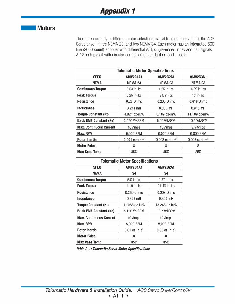
There are currently 5 different motor selections available from Tolomatic for the ACS Servo drive - three NEMA 23, and two NEMA 34. Each motor has an integrated 500 line (2000 count) encoder with differential A/B, single-ended index and hall signals. A 12 inch pigtail with circular connector is standard on each motor.
Tolomatic Motor SpecificationsSPeC AMv2C1A1 AMv2C2A1 AMv2C3A1
NeMA NeMA 23 NeMA 23 NeMA 23
Continuous Torque 2.63 in-lbs 4.25 in-lbs 4.29 in-lbs
Peak Torque 5.25 in-lbs 8.5 in-lbs 13 in-lbs
resistance 0.23 Ohms 0.205 Ohms 0.616 Ohms
Inductance 0.244 mH 0.305 mH 0.915 mH
Torque Constant (Kt) 4.824 oz-in/A 8.189 oz-in/A 14.189 oz-in/A
Back eMF Constant (Ke) 3.570 V/kRPM 6.06 V/kRPM 10.5 V/kRPM
Max. Continuous Current 10 Amps 10 Amps 3.5 Amps
Max. rPM 6,000 RPM 6,000 RPM 6,000 RPM
rotor Inertia 0.001 oz-in-s2 0.002 oz-in-s2 0.002 oz-in-s2
Motor Poles 8 8 8
Max Case Temp 85C 85C 85C
Tolomatic Motor SpecificationsSPeC AMv2d1A1 AMv2d2A1
NeMA 34 34
Continuous Torque 5.9 in-lbs 9.87 in-lbs
Peak Torque 11.9 in-lbs 21.46 in-lbs
resistance 0.250 Ohms 0.208 Ohms
Inductance 0.325 mH 0.399 mH
Torque Constant (Kt) 11.068 oz-in/A 18.243 oz-in/A
Back eMF Constant (Ke) 8.190 V/kRPM 13.5 V/kRPM
Max. Continuous Current 10 Amps 10 Amps
Max. rPM 5,000 RPM 5,000 RPM
rotor Inertia 0.01 oz-in-s2 0.02 oz-in-s2
Motor Poles 8 8
Max Case Temp 85C 85C
Table A-1: Tolomatic Servo Motor Specifications
Tolomatic Hardware & Installation Guide: ACS Servo Drive/Controller • A1_2 •
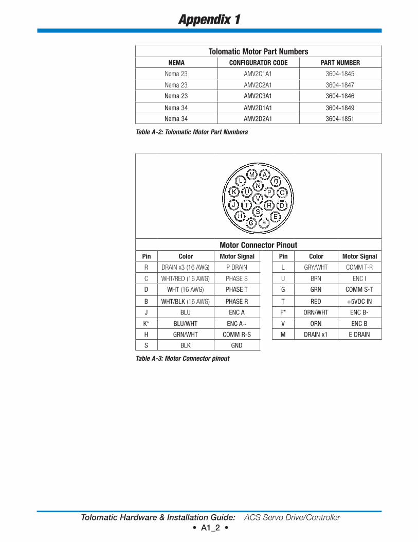
Tolomatic Motor Part NumbersNeMA CoNFIGUrATor Code PArT NUMBer
Nema 23 AMV2C1A1 3604-1845
Nema 23 AMV2C2A1 3604-1847
Nema 23 AMV2C3A1 3604-1846
Nema 34 AMV2D1A1 3604-1849
Nema 34 AMV2D2A1 3604-1851
Table A-2: Tolomatic Motor Part Numbers
Motor Connector PinoutPin Color Motor Signal Pin Color Motor Signal
R DRAIN x3 (16 AWG) P DRAIN L GRY/WHT COMM T-R
C WHT/RED (16 AWG) PHASE S U BRN ENC I
D WHT (16 AWG) PHASE T G GRN COMM S-T
B WHT/BLK (16 AWG) PHASE R T RED +5VDC IN
J BLU ENC A F* ORN/WHT ENC B-
K* BLU/WHT ENC A~ V ORN ENC B
H GRN/WHT COMM R-S M DRAIN x1 E DRAIN
S BLK GND
Table A-3: Motor Connector pinout
Appendix 1
Tolomatic Hardware & Installation Guide: ACS Servo Drive/Controller • A2_1 •
Product warranty
Ce CoMPLIANCe
Tolomatic, Inc. warrants all products manufactured by it to be free from defects in material and workmanship for a period of one year from date of shipment by Tolomatic. If, within this period, any product is proven to be defective by Tolomatic, the product will either be repaired or replaced at Tolomatic’s option.
This warranty shall not apply to:
1. Products not manufactured by Tolomatic. Warranty of these products will conform and be limited to the warranty actually extended to Tolomatic by its supplier.
2. Damage to the product caused by circumstances beyond the control of Tolomatic, such as negligence, improper maintenance, or storage.
3. This warranty shall be void in the case of: any repairs or alterations made to the product by parties other than Tolomatic.
The foregoing warranties are exclusive and in lieu of all other express and implied warranties. Tolomatic is not subject to any other obligations or liabilities for consequential damages.
The ACS Servo Drive is certified to be meet CE emission standard
eN 55011:2009/A1:2010
Industrial, scientific and medical equipment - Radio-frequency disturbance characteristics - Limits and methods of measurement.
And CE immunity standard
eN 61000-6-1:2007
Electromagnetic compatibility (EMC) -- Part 6-1: Generic standards - Immunity for residential, commercial and light-industrial environments.
The above emission and immunity standards can only be guaranteed if high quality shielded cables are used and proper grounding techniques are applied to the installation. Tolomatic recommends that only trained and qualified personal familiar with sound industrial wiring techniques perform the installation. If the ACS Servo Drive is to be included in a system that intends to have emissions and immunity certification Tolomatic recommends that ferrite suppression cores such the Fair-Rite 0431164281 (or similar) be attached to all cables leading to and from the ACS Drive.
Appendix 2

Copyright © 2014 Tolomatic, Inc. All rights Reserved.
All brand and product names are trademarks of their respective owners. Information in this document is believed to be accurate at time of publication.
201411111743

3800 County Road 116, Hamel, MN 55340
Phone: 763.478.8000
Toll Free: 1.800.328.2174
Fax: 763.478.8080
Email: [email protected]
www.tolomatic.com