Acoustics - Gate Precast Company · Page 4 DN-18 Acoustics curved interior wall panels to...
16
Acoustics
-
Upload
nguyenthuan -
Category
Documents
-
view
217 -
download
0
Transcript of Acoustics - Gate Precast Company · Page 4 DN-18 Acoustics curved interior wall panels to...
Acoustics
Color logos
Black only logos
Reverse logos
Page 2 DN-18 Acoustics
ACOUSTICSGeneralThe basic purpose of architectural acoustics is to provide a satisfactory environment in which the desired sounds are clearly heard by the intended listeners and the unwanted sounds (noise) are isolated or absorbed. The sound-reduction needs of a building are determined based on location, environmental ambiance, and the degree of sound reduction necessary for occupants to function effectively.
Under most conditions, the architect can design the building to satisfy the acoustical needs of the tenant. Good acoustical design uses reflective and absorptive surfaces, sound barriers, and vibration isolators. Some surfaces must reflect sound so that the loudness will be adequate in all areas where listeners are located. Other surfaces must absorb sound to avoid echoes, sound distortion, and long reverberation times. Sound is isolated from rooms where it is not wanted by selected wall and floor/ceiling constructions. Vibrations generated by mechanical equip-ment are isolated from the structural frame of the building by means of mechanical isolators or compressible materials.
Most acoustical situations can be described in terms of: (1) sound source, strength, and path; (2) sound transmission path; and (3) sound receiver.
Sound LevelsThe problems of sound insulation are usually considerably more complicated than those of sound absorption. Sound insulation involves greater reductions in sound level than can be achieved by absorption. These large reductions can only be achieved by continuous, impervi-ous barriers. If the problem also involves structure-borne sound, it may be necessary to intro-duce resilient layers or discontinuities into the barrier.
Sound absorbing materials and sound insulating materials are used for two different purposes. There is not much sound absorption from an 8 in. (200 mm) concrete wall; similarly, low sound transmission is not available from a porous, lightweight material that may be applied to room surfaces for sound absorption. It is important to recognize that the basic mechanisms of sound absorption and sound insulation are quite different.
DN- 18 Acoustics Page 3
Sound Transmission LossSound transmission loss measurements are made at 16 frequencies at one-third octave intervals covering the range from 125 to 4000 Hz. The testing procedure is described in ASTM E 90, Laboratory Measurement of Airborne Sound Transmission Loss of Building Partitions. Measurements can also be made in buildings by following ASTM E 336, Measurement of Air-borne Sound Insulation in Buildings. To simplify specification of desired performance characteristics the single number Sound Transmission Class (STC) (see ASTM E 413) was developed. It was originally designed to assess sound (human speech) privacy for interior walls, but its use has expanded to cover virtually all types of partitions and partition elements.
Airborne sound reaching a wall, floor, or ceiling produces vibrations in the wall that are radiated with reduced intensity on the other side. Airborne sound transmission loss in wall assemblies is a function of their weight, stiffness, and vibration damping characteristics.
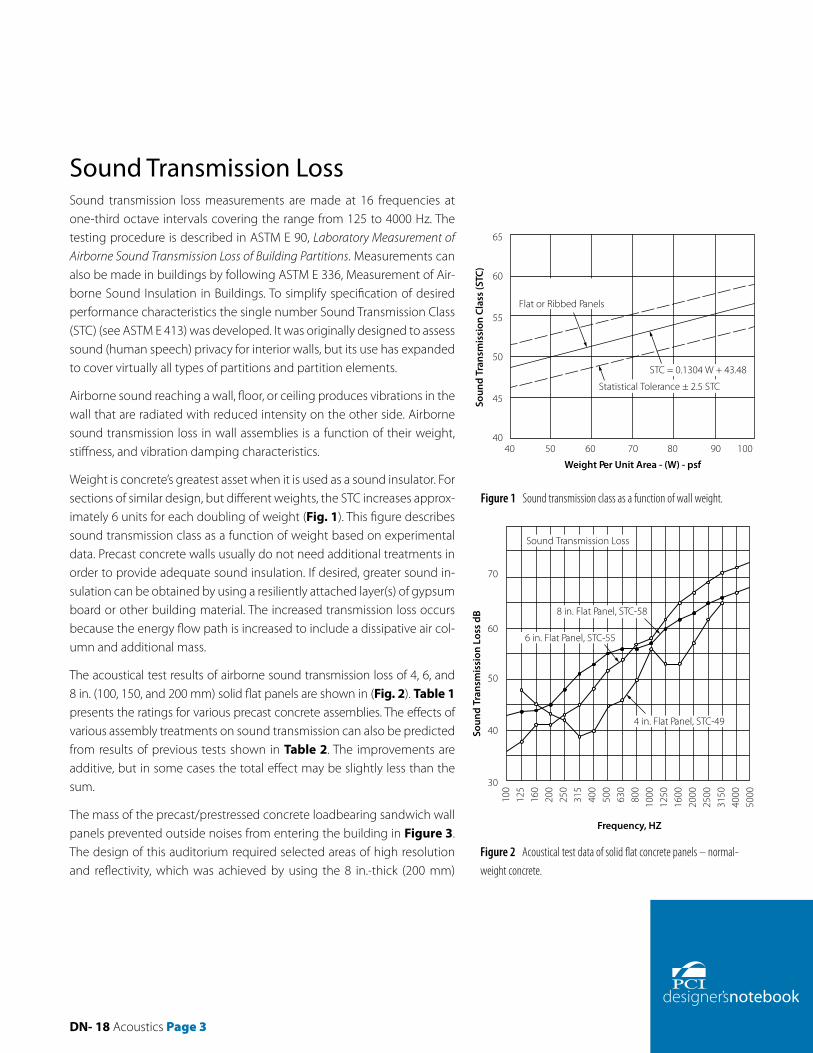
Weight is concrete’s greatest asset when it is used as a sound insulator. For sections of similar design, but different weights, the STC increases approx-imately 6 units for each doubling of weight (Fig. 1). This figure describes sound transmission class as a function of weight based on experimental data. Precast concrete walls usually do not need additional treatments in order to provide adequate sound insulation. If desired, greater sound in-sulation can be obtained by using a resiliently attached layer(s) of gypsum board or other building material. The increased transmission loss occurs because the energy flow path is increased to include a dissipative air col-umn and additional mass.
The acoustical test results of airborne sound transmission loss of 4, 6, and 8 in. (100, 150, and 200 mm) solid flat panels are shown in (Fig. 2). Table 1 presents the ratings for various precast concrete assemblies. The effects of various assembly treatments on sound transmission can also be predicted from results of previous tests shown in Table 2. The improvements are additive, but in some cases the total effect may be slightly less than the sum.
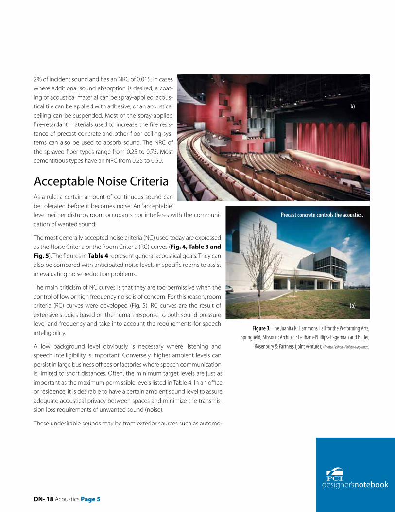
The mass of the precast/prestressed concrete loadbearing sandwich wall panels prevented outside noises from entering the building in Figure 3. The design of this auditorium required selected areas of high resolution and reflectivity, which was achieved by using the 8 in.-thick (200 mm)
STC = 0.1304 W + 43.48
Statistical Tolerance ± 2.5 STC
40 50 60 70 80 90 100
Flat or Ribbed Panels
Soun
d Tr
ansm
issi
on C
lass
(STC
)
65
60
55
50
45
40
Weight Per Unit Area - (W) - psf
8 in. Flat Panel, STC-58
6 in. Flat Panel, STC-55
Frequency, HZ
100
125
160
200
250
315
400
500
630
800
1000
1250
1600
2000
2500
3150
4000
5000
Sound Transmission Loss
Soun
d Tr
ansm
issi
on L
oss
dB
70
60
50
40
30
4 in. Flat Panel, STC-49
Figure 1 Sound transmission class as a function of wall weight.
Figure 2 Acoustical test data of solid flat concrete panels – normal-weight concrete.

Page 4 DN-18 Acoustics
curved interior wall panels to distribute sound throughout the hall in a geometrically con-trolled fashion. They also serve as structural members. Some 200 curved, sandblasted panels, employing eight different radii, were created to meet all of the acoustical requirements. They were given a staining sealer for aesthetic effects.
Absorption of SoundA sound wave always loses part of its energy as it is reflected by a surface. This loss of energy is called sound absorption. It appears as a decrease in sound pressure of the reflected wave. The sound absorption coefficient is the fraction of energy incident but not reflected per unit of surface area. Sound absorption can be specified at individual frequencies or as an average of absorption coefficients (NRC). A dense, non-porous concrete surface typically absorbs 1 to
Table 1 Airborne Sound Transmission Class Ratings from Tests of Precast Concrete Assemblies.
Assembly No. Description STC1 (OITC)
1 4 in. flat panel, 54 psf 49 (43)
2 5 in. flat panel, 60 psf 522
3 6 in. flat panel, 75 psf 55 (46)
4Assembly 2 with “Z” furring channels, 1 in. insulation and 1/2 in. gypsum board, 75.5 psf
62
5Assembly 2 with wood furring, 11/2 in. insulation and 1/2 in. gypsum board, 73 psf
63
6Assembly 2 with 1/2 in. space, 15/8 in. metal stud row, 11/2 in. insulation and 1/2 in. gypsum board
632
7 8 in. flat panel, 95 psf 58 (50)
8 10 in. flat panel, 120 psf 592
1 The STC of sandwich panels is about the same as the STC of the thickness of the two concrete wythes (ignoring the insulation thickness).2 Estimated values.
Table 2 Typical Improvements for Wall Treatments Used with Precast Concrete Elements.
Treatment Increaesd Airborne STC
Wall furring, 3/4 in. insulation and 1/2 in. gypsum board attached to concrete wall 3
Separate metal stud system, 11/2 in. insulation in stud cavity and 1/2 in. gypsum board attached to concrete wall 5 to 10
Plaster direct to concrete 0
DN- 18 Acoustics Page 5
2% of incident sound and has an NRC of 0.015. In cases where additional sound absorption is desired, a coat-ing of acoustical material can be spray-applied, acous-tical tile can be applied with adhesive, or an acoustical ceiling can be suspended. Most of the spray-applied fire-retardant materials used to increase the fire resis-tance of precast concrete and other floor-ceiling sys-tems can also be used to absorb sound. The NRC of the sprayed fiber types range from 0.25 to 0.75. Most cementitious types have an NRC from 0.25 to 0.50.
Acceptable Noise CriteriaAs a rule, a certain amount of continuous sound can be tolerated before it becomes noise. An “acceptable” level neither disturbs room occupants nor interferes with the communi-cation of wanted sound.
The most generally accepted noise criteria (NC) used today are expressed as the Noise Criteria or the Room Criteria (RC) curves (Fig. 4, Table 3 and Fig. 5). The figures in Table 4 represent general acoustical goals. They can also be compared with anticipated noise levels in specific rooms to assist in evaluating noise-reduction problems.
The main criticism of NC curves is that they are too permissive when the control of low or high frequency noise is of concern. For this reason, room criteria (RC) curves were developed (Fig. 5). RC curves are the result of extensive studies based on the human response to both sound-pressure level and frequency and take into account the requirements for speech intelligibility.
A low background level obviously is necessary where listening and speech intelligibility is important. Conversely, higher ambient levels can persist in large business offices or factories where speech communication is limited to short distances. Often, the minimum target levels are just as important as the maximum permissible levels listed in Table 4. In an office or residence, it is desirable to have a certain ambient sound level to assure adequate acoustical privacy between spaces and minimize the transmis-sion loss requirements of unwanted sound (noise).
These undesirable sounds may be from exterior sources such as automo-
Figure 3 The Juanita K. Hammons Hall for the Performing Arts, Springfield, Missouri; Architect: Pellham-Phillips-Hagerman and Butler,
Rosenbury & Partners (joint venture); (Photos Pellham-Phillips-Hagerman)
(b)
(a)
Precast concrete controls the acoustics.
Page 6 DN-18 Acoustics
biles and aircraft, or they may be generated as speech in an adjacent classroom or music in an adjacent apartment. They may also be direct impact-induced sound such as footfalls on the floor above, rain on a lightweight roof construction, or vibrating mechanical equipment. Thus, the designer must always be ready to accept the task of analyzing the many potential sources of intruding sound as related to their frequency characteristics and the rates at which they occur. The level of toleration that is to be expected by those who will occupy the space must also be established. Figures 6 and 7 are the spectral characteristics of common noise sources.
With these criteria, the problem of sound isolation now must be solved, namely the reduction process between the high, unwanted noise source and the desired ambient level. Once the objectives are established, the designer then should refer to available data (for example in Fig. 1 or Table 1) and select the system that best meets these requirements. In this respect, precast concrete systems have superior properties and can, with minimal effort, comply with these criteria. When the insulation value has not been specified, selection of the necessary barrier can be determined analytically by (a) identifying exterior and /or interior noise sources, and (b) by establishing acceptable interior noise criteria.
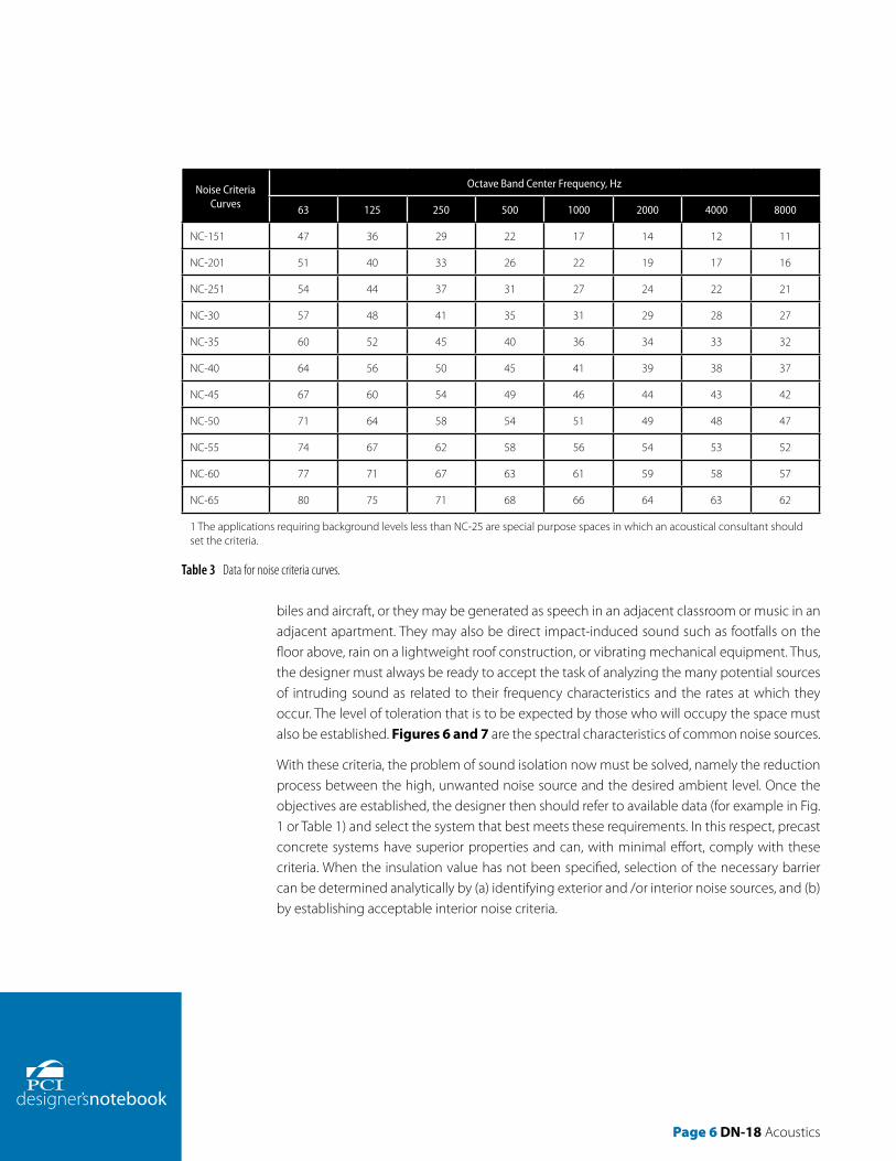
Table 3 Data for noise criteria curves.
Noise Criteria Curves
Octave Band Center Frequency, Hz
63 125 250 500 1000 2000 4000 8000
NC-151 47 36 29 22 17 14 12 11
NC-201 51 40 33 26 22 19 17 16
NC-251 54 44 37 31 27 24 22 21
NC-30 57 48 41 35 31 29 28 27
NC-35 60 52 45 40 36 34 33 32
NC-40 64 56 50 45 41 39 38 37
NC-45 67 60 54 49 46 44 43 42
NC-50 71 64 58 54 51 49 48 47
NC-55 74 67 62 58 56 54 53 52
NC-60 77 71 67 63 61 59 58 57
NC-65 80 75 71 68 66 64 63 62
1 The applications requiring background levels less than NC-25 are special purpose spaces in which an acoustical consultant should set the criteria.

DN- 18 Acoustics Page 7
Example: Sound Insulation CriteriaAssume a precast concrete office building is to be erected adjacent to a ma-jor highway. Private and semiprivate offices will run along the perimeter of the structure. The first step is to determine the degree of insulation required of the exterior wall system (see Sound Pressure Level 1, page 10). The NC data is used because it is more familar to and preferred by designers.
The 500 Hz requirement, 38 dB, can be used as the first approximation of the wall STC category. However, if windows are planned for the wall, a sys-tem of about 50–55 STC should be selected (see following composite wall discussion). Individual transmission loss performance values of this system are then compared to the calculated need (see Sound Pressure Level 2).
The selected wall should meet or exceed the insulation needs at all fre-quencies. However, to achieve the most efficient design conditions, certain limited deficiencies can be tolerated. Experience has shown that the maxi-mum deficiencies are 3 dB at two frequencies or 5 dB on one frequency point.
Composite Wall ConsiderationsAn acoustically composite wall is made up of elements of varying acous-tical properties. Windows and doors are often the weak link in an otherwise effective sound barrier. Minimal effects on sound transmission loss will be achieved in most cases by proper selection of glass (Table 5). The control of sound transmission through windows requires large cavities between layers (multiple glazing), heavy layers (thicker glass), laminated glass, and reduction of the structural connection between layers (separate frames and sashes for inner and outer layers). Also, mounting of glass lites with soft neoprene edge gaskets may not be as effective at reducing sound transmission as systems that use wet seals (gunable sealants). The combination of wet seals with butyl tape or open cell foam dramatically reduces the potential for air infiltration, and therefore, flanking sound transmission. They certainly have to be as air-tight as possible; usually fixed windows provide much better sound transmission control than operable windows.
Sound pressure impinging on the window framing will cause it to vibrate, transmitting sound to the building interior. Consequently, the window-glass performance cannot solely be relied on to reduce sound transmission to the building interior. The sound transmission of the win-dow framing will result in higher levels of sound transmission through the glass and wall. Also, windowframing systems that allow greater amounts of air infiltration also allow greater sound transmission.
90
80
70
60
50
40
30
20
1016 125 250 500 1000 2000 4000 8000
Oct
ave
Band
Sou
nd P
ress
ure
Leve
l, dB
re 2
0 m
icro
pasc
als
Octave Band Center Frequencies, Hz
Approximate threshold of hearing for continuous noise
NC-65
NC-60
NC-55
NC-50
NC-45
NC-40
NC-35
NC-30
NC-25
NC-20
NC-15
Figure 4 Noise criteria (NC) curves.

Page 8 DN-18 Acoustics
STC is not necessarily the best performance specification for windows as it is often a poor pre-dictor of sound insulation for low frequency sources, such as me-chanical system or transportation noise. The OITC (Outdoor- Indoor Transmission Class) rating system based on ASTM E 1332 is relatively new, and it was designed to as-sess a building façade element, such as a window, when exposed to a standard spectrum of low frequency air and truck transpor-tation noise ranging from 80 to 4000 Hz (see ASTM Guide E 966). Therefore, it is a better measure of a window system’s performance than STC, especially when traffic noise is the principal concern. The numeric value representation of OITC tends to be lower than the STC rating.
There are many options available for acoustical glazing, so it is impor-tant to make the right choice—es-pecially if the building is exposed to significant exterior noise and the interior spaces are noise sen-sitive. The use of doublepane insulating glass is not adequate for many projects. Even single- or double-laminated insulating glass may not be adequate, especially at low outside temperatures, where regular PVB-laminated glass will yield a performance similar to that of non-laminated glass.
Type of Space NC or RC Curve
1. Private residence 25 to 30
2. Apartments 30 to 35
3. Hotels/motels
a. Individual rooms or suites 30 to 35
b. Meeting/banquet rooms 30 to 35
c. Halls, corridors, lobbies 35 to 40
d. Services/support areas 40 to 45
4. Offices
a. Executive 25 to 30
b. Conference rooms 25 to 30
c. Private 30 to 35
d. Open-Plan areas 35 to 40
e. Computer/business machine areas 40 to 45
f. Public circulation 40 to 45
5. Hospitals and clinics
a. Private rooms 25 to 30
b. Wards 30 to 35
c. Operating rooms 25 to 30
d. Laboratories 30 to 35
e. Corridors 30 to 35
f. Public areas 35 to 40
6. Churches 25 to 302
7. Schools
a. Lecture and classrooms 25 to 30
b. Open-Plan classrooms 30 to 352
8. Libraries 30 to 35
9. Concert halls2
10. Legitimate theaters2
11. Recording studios2
12. Movie theaters 30 to 35
1 Design goals can be increased by 5dB when dictated by budget constraints or when noise intrusion from other sources represents a limiting condition.2 An acoustical expert should be consulted for guidance on these critical spaces.
Table 4 Recommended Category Classification and Suggested Noise Criteria Range for Steady Background Noise as Heard in Various Indoor Functional Activity Areas.1

DN- 18 Acoustics Page 9
The sound-transmission loss through a door depends on the material and construction of the door and the effectiveness of the seal between the door and its frame. There is a mass law dependence of STC on weight (psf ) for both wood and steel doors. The approximate relationships are:
For steel doors: STC = 15 + 27 log W
For wood doors: STC = 12 + 32 log W
where W = weight of the door, psf.
These relationships are purely empirical and a large deviation can be ex-pected for any given door. ASTM E 1408 can be used to determine the acoustical performance of doors.
For best results, the distances between adjacent door and/or window open-ings should be maximized, staggered when possible, and held to a minimum area. Minimizing openings allows the wall to retain the acoustical properties of the precast concrete. The design characteristics of the door or window systems must be analyzed prior to specification. Such qualities as frame de-sign, door construction, and glazing thickness are vital performance criteria. Installation procedures must be exact and care should be given to the fram-ing of each opening. Gaskets, weatherstripping, and raised thresholds serve as both thermal and acoustical seals and are recommended.
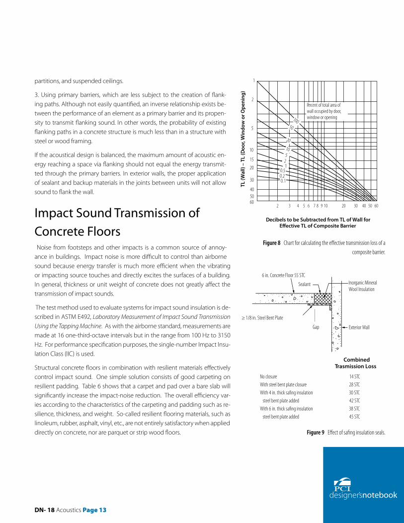
Figure 8 can be used to calculate the effective acoustic isolation of a wall system that contains a composite of elements, each with known individual transmission loss data (TL). (For purposes of approximation, STC values can be used in place of TL values.)
Example: Composite Wall Insulation CriteriaTo complete the office building wall acoustical design from page 41 assume
the following:
1. The glazing area represents 10% of the exterior wall area.
2. The windows will be double glazed with a 40 STC acoustical insulation rating.
The problem now becomes the test of determining the combined effect of the concrete-glass combination and a re-determination of criteria compliance (see Sound Pressure Level 3).
The maximum deficiency is 3 dB and occurs at only one frequency point. The 6 in. (150 mm) precast concrete wall with double-glazed windows will provide the required acoustical insula-
B
90
80
70
60
50
40
30
20
1016 31.5 63 125 250 500 1000 2000 4000
A
C
RC
50
45
40
35
30
25
Oct
ave
Band
Sou
nd P
ress
ure
Leve
l, dB
re 2
0 m
icro
pasc
als
Region A: High probability that noise-induced vibration levels in lightweight wall/ceiling constructions will be clearly perceptible; anticipate audible rattles in low mass �xtures, doors, windows, etc.
Region B: Noise-induced vibration levels in lightweight wall/ceiling constructions may be moderately perceptible; slight possibility of rattles in low mass �xtures, doors, windows, etc.
Region C: Below threshold of hearing for continuous noise.
Octave Band Center Frequencies, Hz
Figure 5 Room criteria (RC) curves.

Page 10 DN-18 Acoustics
tion.
Floor-ceiling assembly acoustical insulation requirements are determined in the same manner as walls by using Fig. 2 and 8.
Leaks and FlankingPerformance of a building section with an otherwise adequate STC can be seriously reduced by a relatively small hole (or any other path) that allows sound to bypass the acoustical barrier. All noise that reaches a space by paths other than through the primary barrier is called flanking noise. Common flanking paths are openings around doors or windows, electrical outlets, tele-
Sound Pressure Level – (dB)
Frequency (Hz) 63 125 250 500 1000 2000 4000 8000
Bus traffic source noise (Fig. 6) 80 83 85 78 74 68 62 58
Private office noise criteria – NC 35 (Fig. 4)
60 52 45 40 36 34 33 32
Required insulation 20 31 40 38 38 34 29 26
Sound Pressure Level 1.
Bus
Propeller Aircraft Takeo� 500 ft
Jet Aircraft Takeo�500 ft
Heavy Truck – 20 ft
Automobiles – 20 ft
Frequency, Hz
Soun
d Pr
essu
re L
evel
, dB
63 125 250 500 1000 2000 4000 8000
120
100
80
60
40
20
0
Frequency, Hz
Soun
d Pr
essu
re L
evel
, dB
63 125 250 500 1000 2000 4000 8000
120
100
80
60
40
20
0
Riveting
Typical O�ce
Bed or Dining Room
Kitchen
Stereo Phnograph,Teenager Lever
Business MachineTabulating Room
Figure 6 Sound pressure levels — exterior noise sources. Figure 7 Sound pressure levels — interior noise sources.
DN- 18 Acoustics Page 11
phone and television connections, and pipe and duct penetrations. Suspended ceilings in rooms where walls do not extend from the ceiling to the roof or floor above also allow sound to travel to adjacent rooms by flanking.
Anticipation and prevention of leaks begins at the design stage. Flanking paths (gaps) at the perimeters of interior precast concrete walls and floors are generally sealed during construc-tion with grout or drypack. All openings around penetrations through walls or floors should be as small as possible and must be sealed airtight. The higher the required STC of the barrier, the greater the importance of sealing all openings.
Perimeter leakage commonly occurs at the intersection between an exterior cladding panel and a floor slab. It is of vital importance to seal this gap to retain the acoustical integrity of the system and provide the required fire stop between floors. One way to seal the gap is to place a 4 pcf (64 kg/m3) density mineral wool blanket between the floor slab and the exterior wall. Figure 9 demonstrates the acoustical isolation effects of this treatment. An enhancement to Fig. 9 would be to recess the insulation below the floor plane and fill the recess with smoke stop elastomeric
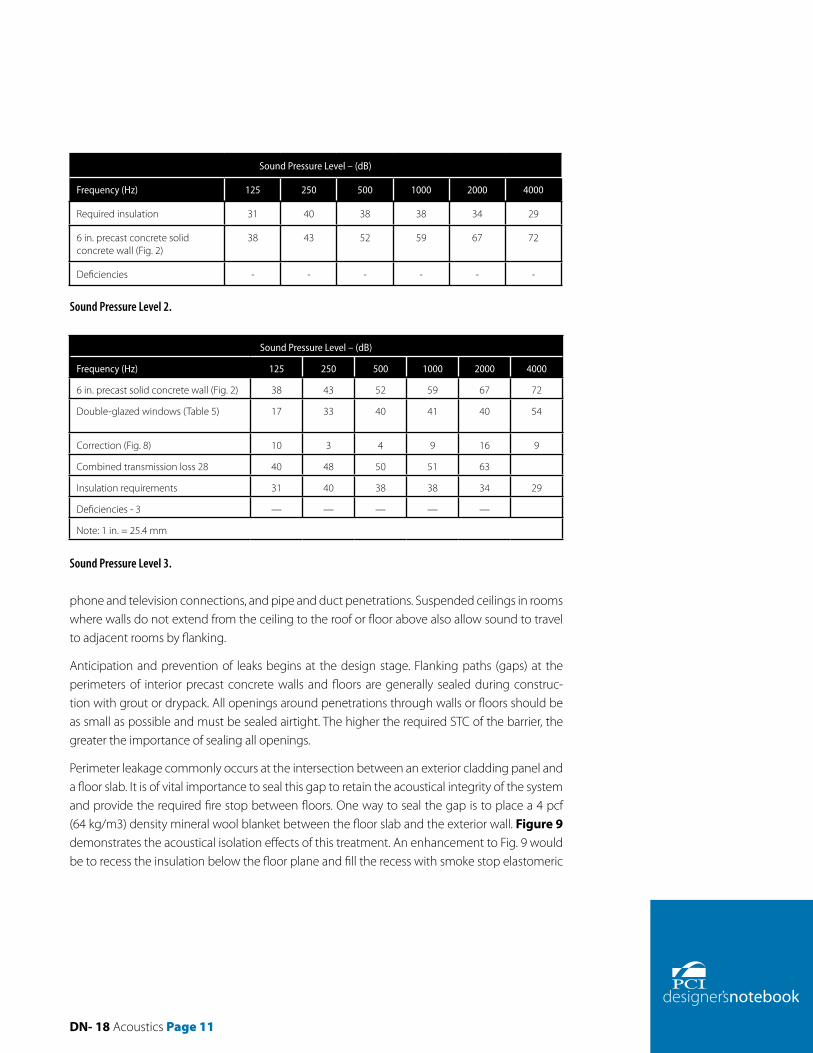
Sound Pressure Level – (dB)
Frequency (Hz) 125 250 500 1000 2000 4000
Required insulation 31 40 38 38 34 29
6 in. precast concrete solid concrete wall (Fig. 2)
38 43 52 59 67 72
Deficiencies - - - - - -
Sound Pressure Level – (dB)
Frequency (Hz) 125 250 500 1000 2000 4000
6 in. precast solid concrete wall (Fig. 2) 38 43 52 59 67 72
Double-glazed windows (Table 5) 17 33 40 41 40 54
Correction (Fig. 8) 10 3 4 9 16 9
Combined transmission loss 28 40 48 50 51 63
Insulation requirements 31 40 38 38 34 29
Deficiencies - 3 — — — — —
Note: 1 in. = 25.4 mm
Sound Pressure Level 2.
Sound Pressure Level 3.

Page 12 DN-18 Acoustics
sealant. Thereby improving not only the sound but the smoke resistance of the assembly.
Flanking paths can be minimized by:
1. Interrupting the continuous flow of energy with dissimilar materials, that is, expansion or con-trol joints or air gaps.
2. Increasing the resistance to energy flow with floating floor systems, full height and/or double
Table 5 Acoustical properties of glass.
Transmission loss (dB)
Frequency (Hz)
125 160 200 250 315 400 500 630 800 1000 1250 1600 2000 2500 3150 4000
1/4 in. plate glass – 31 STC; 29 OITC
25 25 24 28 26 29 31 33 34 34 35 34 30 27 32 37
1 in. insulating glass with 1/2 in. air space – 35 STC; 28 OITC
24 29 22 22 25 30 33 35 38 40 42 42 37 37 43 46
1 in. insulating glass laminated with 1/2 in. air space – 39 STC; 31 OITC
17 28 29 33 34 38 40 40 41 41 41 41 40 43 49 54
Sound Transmission Class (STC)
Type and Overall Thickness, in. Inside Lite, in.Construction Space,
in. .Outside Lite, in STC OITC
5/8 Insulated Glass 1/83/8
1/8 31 26
1/4 Plate or Float — — 1/4 31 29
1/2 Plate or Float — — 1/2 36 32
1 Insulated glass 1/41/2 Air space 1/4 35 28-30
1/4 Laminated 1/4 0.030 Vinyl 1/8 35 —
11/2 Insulated glass 1/49/16 Air space 3/16 37 28-30
3/4 Plate or Float — — 3/4 36 —
1 Insulated glass 1/4 Laminated 1/2 Air space 1/4 39 31
1 Plate or Float — — 1 37 —
23/4 Insulated glass 1/4 2 Air space 1/2 39 —
1 Laminated Insulated glass 1/41/2 Air space 1/8 plus 1/8 41 32
DN- 18 Acoustics Page 13
partitions, and suspended ceilings.
3. Using primary barriers, which are less subject to the creation of flank-ing paths. Although not easily quantified, an inverse relationship exists be-tween the performance of an element as a primary barrier and its propen-sity to transmit flanking sound. In other words, the probability of existing flanking paths in a concrete structure is much less than in a structure with steel or wood framing.
If the acoustical design is balanced, the maximum amount of acoustic en-ergy reaching a space via flanking should not equal the energy transmit-ted through the primary barriers. In exterior walls, the proper application of sealant and backup materials in the joints between units will not allow sound to flank the wall.
Impact Sound Transmission of Concrete Floors Noise from footsteps and other impacts is a common source of annoy-ance in buildings. Impact noise is more difficult to control than airborne sound because energy transfer is much more efficient when the vibrating or impacting source touches and directly excites the surfaces of a building. In general, thickness or unit weight of concrete does not greatly affect the transmission of impact sounds.
The test method used to evaluate systems for impact sound insulation is de-scribed in ASTM E492, Laboratory Measurement of Impact Sound Transmission Using the Tapping Machine. As with the airborne standard, measurements are made at 16 one-third-octave intervals but in the range from 100 Hz to 3150 Hz. For performance specification purposes, the single-number Impact Insu-lation Class (IIC) is used.
Structural concrete floors in combination with resilient materials effectively control impact sound. One simple solution consists of good carpeting on resilient padding. Table 6 shows that a carpet and pad over a bare slab will significantly increase the impact-noise reduction. The overall efficiency var-ies according to the characteristics of the carpeting and padding such as re-silience, thickness, and weight. So-called resilient flooring materials, such as linoleum, rubber, asphalt, vinyl, etc., are not entirely satisfactory when applied directly on concrete, nor are parquet or strip wood floors.
Decibels to be Subtracted from TL of Wall for E�ective TL of Composite Barrier
1
2
5
10
15
20
30
405060
2 3 4 5 6 7 8 9 10 20 30 40 50 60
Percent of total area of wall occupied by door, window or opening
TL (W
all)
– TL
(Doo
r, W
indo
w o
r Ope
ning
)
10050
20
105
21
0.50.20.1
Combined Trasmission Loss
No closure 14 STCWith steel bent plate closure 28 STCWith 4 in. thick sa�ng insulation 30 STC steel bent plate added 42 STCWith 6 in. thick sa�ng insulation 38 STC steel bent plate added 45 STC
6 in. Concrete Floor 55 STCInorganic Mineral Wool Insulation
1/8 in. Steel Bent Plate
Gap Exterior Wall
Sealant
≥
Figure 8 Chart for calculating the effective transmission loss of a composite barrier.
Figure 9 Effect of safing insulation seals.
Page 14 DN-18 Acoustics
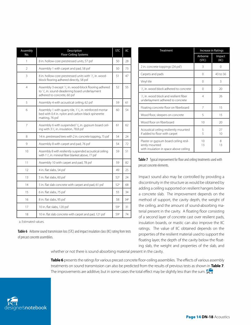
Impact sound also may be controlled by providing a discontinuity in the structure as would be obtained by adding a ceiling supported on resilient hangers below a concrete slab. The improvement depends on the method of support, the cavity depth, the weight of the ceiling, and the amount of sound-absorbing ma-terial present in the cavity. A floating floor consisting of a second layer of concrete cast over resilient pads, insulation boards, or mastic can also improve the IIC ratings. The value of IIC obtained depends on the properties of the resilient material used to support the floating layer, the depth of the cavity below the float-ing slab, the weight and properties of the slab, and
whether or not there is sound-absorbing material present in the cavity.
Table 6 presents the ratings for various precast concrete floor-ceiling assemblies. The effects of various assembly treatments on sound transmission can also be predicted from the results of previous tests as shown in Table 7. The improvements are additive, but in some cases the total effect may be slightly less than the sum.
Assembly No.
DescriptionFloor-Ceiling Systems
STC IIC
1 8 in. hollow-core prestressed units, 57 psf 50 28
2 Assembly 1 with carpet and pad, 58 psf 50 73
3 8 in. hollow-core prestressed units with 1/2 in. wood-block flooring adhered directly, 58 psf
51 47
4 Assembly 3 except 1/2 in. wood-block flooring adhered to 1/2 in. sound-deadening board underlayment adhered to concrete, 60 psf
52 55
5 Assembly 4 with acoustical ceiling, 62 psf 59 61
6 Assembly 1 with quarry tile, 11/4 in. reinforced mortar bed with 0.4 in. nylon and carbon black spinerette matting, 76 psf
60 54
7 Assembly 6 with suspended 5/8 in. gypsum board ceil-ing with 31/2 in. insulation, 78.8 psf
61 62
8 14 in. prestressed tees with 2 in. concrete topping, 75 psf 54 24
9 Assembly 8 with carpet and pad, 76 psf 54 72
10 Assembly 8 with resiliently suspended acoustical ceiling with 11/2 in. mineral fiber blanket above, 77 psf
59 51
11 Assembly 10 with carpet and pad, 78 psf 59 82
12 4 in. flat slabs, 54 psf 49 25
13 5 in. flat slabs, 60 psf 52a 24
14 5 in. flat slab concrete with carpet and pad, 61 psf 52a 68
15 6 in. flat slabs, 75 psf 55 34
16 8 in. flat slabs, 95 psf 58 34a
17 10 in. flat slabs, 120 psf 59a 31
18 10 in. flat slab concrete with carpet and pad, 121 psf 59a 74
a. Estimated values.
Treatment Increase in Ratings
Airborne (STC)
Impact (IIC)
2 in. concrete toppings (24 psf ) 3 0
Carpets and pads 0 43 to 56
Vinyl tile 0 3
1/2 in. wood block adhered to concrete 0 20
1/2 in. wood block and resilient fiber underlayment adhered to concrete
4 26
Floating concrete floor on fiberboard 7 15
Wood floor, sleepers on concrete 5 15
Wood floor on fiberboard 10 20
Acoustical ceiling resiliently mountedif added to floor with carpet
55
2710
Plaster or gypsum board ceiling resil-iently mountedwith insulation in space above ceiling
1013
813
Table 6 Airborne sound transmission loss (STC) and impact insulation class (IIC) rating from tests of precast concrete assemblies.
Table 7 Typical improvement for floor and ceiling treatments used with precast concrete elements.

DN- 18 Acoustics Page 15

200 West Adams Street I Suite 2100 I Chicago, IL 60606-5230Phone: 312-786-0300 I Fax: 312-621-1114 I www.pci.org
200 West Adams StreetSuite 2100 Chicago, IL 60606
Phone: 312-786-0300Fax: 312-621-1114
www.pci.org
200 West Adams Street I Suite 2100 I Chicago, IL 60606-5230Phone: 312-786-0300 I Fax: 312-621-1114 I www.pci.org
200 West Adams StreetSuite 2100 Chicago, IL 60606
Phone: 312-786-0300Fax: 312-621-1114
www.pci.org
200 West Adams Street I Suite 2100 I Chicago, IL 60606-5230Phone: 312-786-0300 I Fax: 312-621-1114 I www.pci.org
200 West Adams StreetSuite 2100 Chicago, IL 60606
Phone: 312-786-0300Fax: 312-621-1114
www.pci.org