Reflective & Absorptive Acoustic Fencing | Acoustic Gates ...
Acoustic Well Stimulation of near-wellbore zone for enhanced oil recovery
Gennadiy GilevCommercial DirectorLLC«Center of Ultrasound Technology - Service»+7 985 920 7426
2
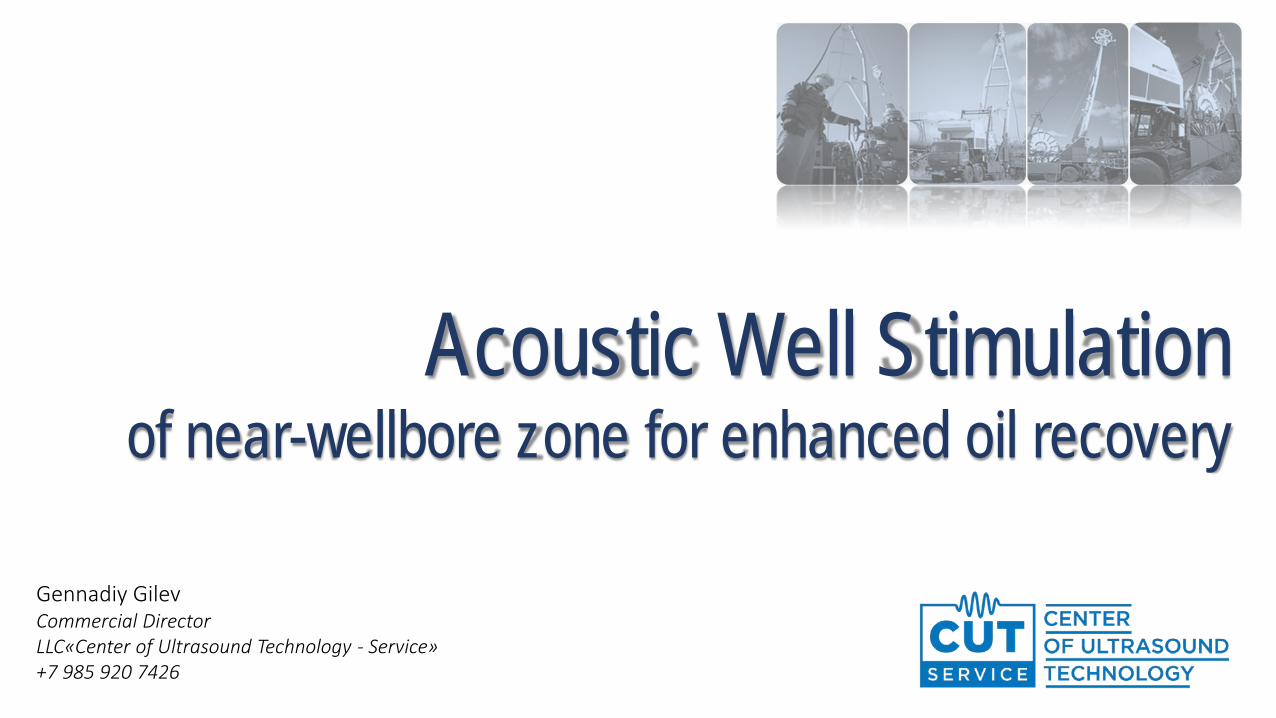
About company 3
Treatment of wells with Light Oil 7
Treatment of wells with Heavy and Viscous Oil 16
Physical properties of ultrasonic exposure 24
Technology advantages 29
Confirmation of efficiency 30
TABLE OF CONTENTS

3
The group of companies specializes in the development of ultrasonic
technology and software systems for enhanced oil recovery and own
dozens of patents. Engineering company awarded with diplomas of
Russian and international exhibitions.
LLC “Viatech” – R&D, manufacturing of ultrasonic equipment
LLC “Sonotech” – Services with permanent treatment solutions on
territory of Tatarstan republic from 2014.
LLC «CUT-Services» - Services of ultrasonic treatment on territory of
Russian Federation and International projects from 2010
GROUP OF COMPANIES VIATECH

4
Abramov Oleg Vladimirovich (25.02.1936 – 25.09.2008)Founder of AWS technology, one of first scientists in the world who implemented acoustic fields in
the oil wells cleaning application
Scientific background:1959 – 1975 Central research Institute of ferrous metallurgy
1975 – 1989 Institute of solid state physics, USSR Academy of Sciences
1990 – 2008 Institute of General and inorganic chemistry, Russian Academy of Sciences
His main area of research - the study the influence of power ultrasound to the substance, its practical use in metallurgy,engineering, chemistry for the intensification of heat and mass transfer processes and impact on the structure andproperties of materials.
Oleg Abramov was a major, globally recognized expert in the field of interaction of ultrasound with matter. He publishedmore than 250 scientific works, including 7 books and chapters in books (4 of them published abroad – in the UnitedStates, England, Germany, Slovakia), more than 220 papers and received more than 30 inventor's certificates. He was thehead of the 25 graduate students who have defended PhD thesis, 4 of his students defended their doctoral dissertations.
HISTORY OF ULTRASONIC DEVELOPMENT IN VIATECH
5
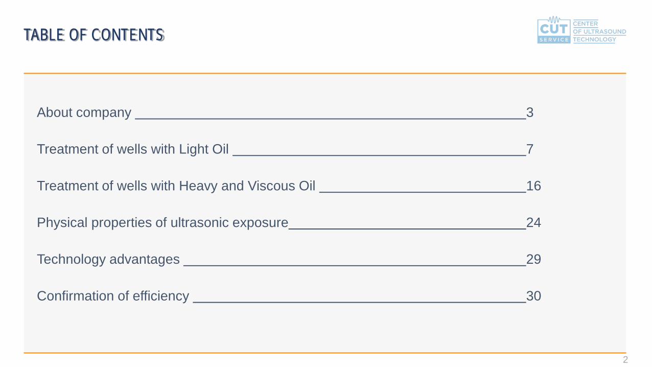
Abramov Vladimir Olegovich Lead scientist who driving ultrasonic research all his life.
Co-founder and co-owner of group of companies VIATECH
Scientific background:1985 – 1993 Central research Institute of ferrous metallurgy
1993 – 1996 Germany, Max-Planck-Institut für Metallforschung, Institut für Werkstoffwissenschaft
From 1996 Institute of General and inorganic chemistry, Russian Academy of Sciences
His main area of research – theory of ultrasonic vibrations, the introduction of ultrasound in metals and alloys, the effect of
ultrasound on physico-chemical and technological processes, including wastewater treatment, recovery of oil wells, oil
refining and chemical conversion to oil products.
Vladimir Abramov is the author of over 100 scientific publications and patents.
Ultrasonic equipment and technology cycles, developed under the leadership of Vladimir Abramov, implemented and are
successfully functioning in Russia and more than 25 foreign countries.
HISTORY OF ULTRASONIC DEVELOPMENT IN VIATECH

6
Service base of LLC «Centre of Ultrasonic Technologies - Services» is located on the territory of 23 375 m2
Located on the territory:• Administrative building – 375 m2
• Workshop – 1600 m2
• 2 Arched Warehouses – 800 m2 each• The base is equipped with its own boiler, water supply system, a backup diesel generator
Abilities:Up to 100 AWS operations monthly by 5 mobile fleets
Unit 1 based on Ural 4320 – from 2011
Unit 2 based on Ural 4320 – from 2012
Unit 3 based on Kamaz 43118 – from 2013
Unit 4 based on Kamaz 43118 – from 2014
Unit 5 based on Ural 4320 – from 2015
LLC «CENTRE OF ULTRASONIC TECHNOLOGIES - SERVICES»

7
TREATMENT OF WELLS WITH LIGHT OIL

8
Decrease the permeability of the near-wellbore zone may be caused by many factors, which
depends both on the properties of the rock and the mode and technology of well operation,
including the most common causes of declining productivity of wells can be:
• Mudding of a near-wellbore zone of the reservoir during drilling a well
• Mudding of a near-wellbore zone of the reservoir during well life (waxing, skin increase)
• Formation of crust in perforation channels after cumulative perforation
• Clogging of perforation channels and pores of rock during the process of killing the well and subsequent
increase of pressure gradient between formation and the wellbore
ISSUES ASSOCIATED WITH OIL RECOVERY REDUCTION

9
Destruction of the boundary layer, confining globule mud
filtrate and other particles in the rock pores
Removal of contaminants from the rock
Improving communication of well - formation system
Improving well productivity from the first hours
Preserving effect up to 2 years during continuous flow
from the well
NEAR-WELLBORE ZONE CLEANUP AFTER DRILLING
Pressure in well before AWS
Near-wellbore zone pressure
Initial formation pressure
Well
Dam
aged
zone
(ski
n) b
efor
e AW
S
Distance
Pres
sure
dPskin = pressure loss in damaged zone before AWS*
Reducing resistance of near-wellbore zone=
Productivity increase

10
Destruction of the boundary layer, confining globule mud
filtrate and other particles in the rock pores
Removal of contaminants from the rock
Improving communication of well - formation system
Improving well productivity from the first hours
Preserving effect up to 2 years during continuous flow
from the well
NEAR-WELLBORE ZONE CLEANUP AFTER DRILLING
Pressure in well after AWS
Near-wellbore zone pressure
Initial formation pressure
Well
Dam
aged
zone
(ski
n) a
fter
AW
S
Distance
Pres
sure
dPskin = pressure loss in damaged zone before AWS*
Reducing resistance of near-wellbore zone=
Productivity increase

11
Destruction of the boundary layer, confining particles of debris in the perforation channels
Detachment crust formed by the cumulative jet, from the rock in the perforation channel
Required to ensure well flowing during AWS to clean perforation channels from debris and crust
Improving communication of well - formation system
Improving well productivity from the first hours
Preserving effect up to 2 years during continuous flow from the well
CLEANING OF PERFORATION CHANNELS FROM THE DEBRIS AND CRUST
Reducing resistance on the boundary of perforation channels=
Productivity increase
12
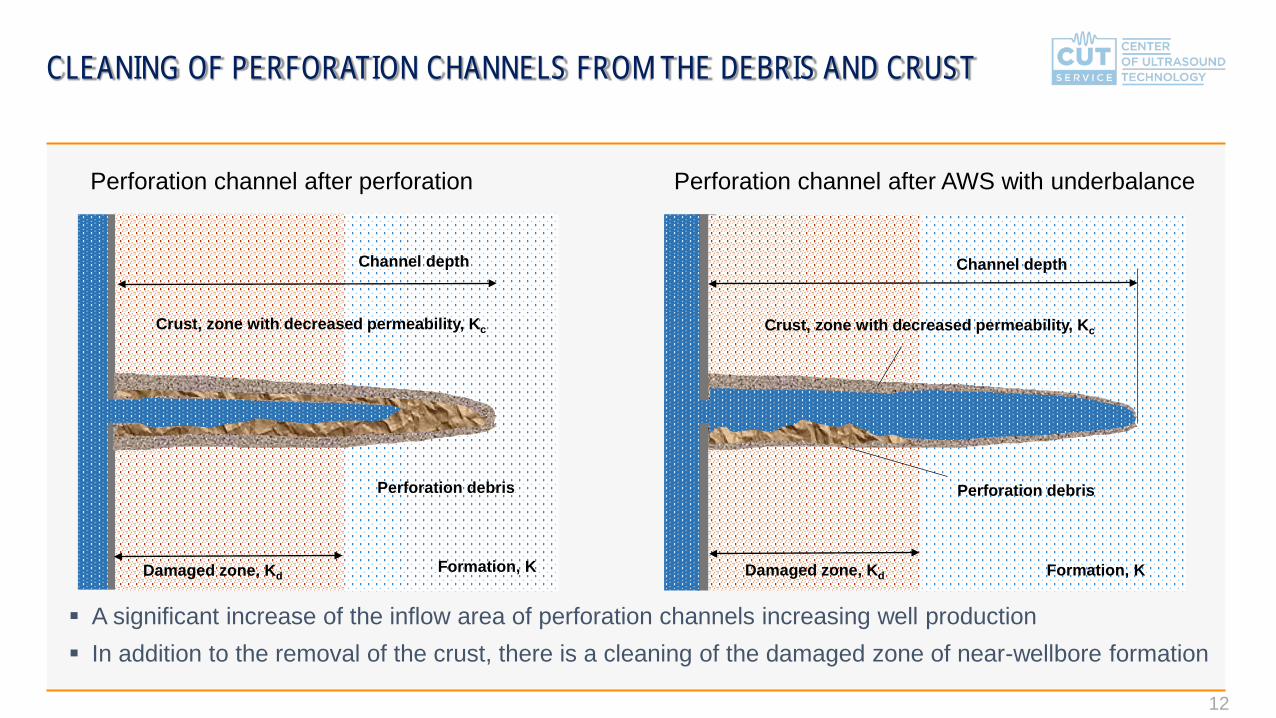
CLEANING OF PERFORATION CHANNELS FROM THE DEBRIS AND CRUST
Damaged zone, KdFormation, K
Channel depth
Crust, zone with decreased permeability, Kc
Perforation debris
Perforation channel after perforation Perforation channel after AWS with underbalance
A significant increase of the inflow area of perforation channels increasing well production In addition to the removal of the crust, there is a cleaning of the damaged zone of near-wellbore formation
Damaged zone, Kd Formation, K
Crust, zone with decreased permeability, Kc
Perforation debris
Channel depth

13
• Operations on the wells with light and moderate oil
• AWS equipment contains surface ultrasonic generator and acoustic well oscillator connected by 3-wired cable.
• The main component of downhole tool is acoustic oscillator (magnetostrictive or piezoceramic), which transform electric power to mechanical vibrations in ultrasonic range.
• Diameter of downhole tool is 42 or 44 мм. Acoustic oscillator run in the well through tubing, power supply provided through wireline cable.
1 – Lubricator2 – Wireline unit3 – Downhole tool4 – Casing5 – Oil formation6 – Acoustic treatment zone 7 – Perforation interval8 – Wireline cable9 – Tubing
Advantages:1. High commercial efficiency
2. Production growth 50% and higher
3. Quick operations
4. Environmental & ecological safety
5. Unlimited iterations on each well
6. Continuous effect from 6 to 24 month
TEMPORARY ACOUSTIC WELL STIMULATION SERVICES

CAPABILITIES OF ULTRASONIC TREATMENT
EXAMPLE: Light oil
* - for clarity of the overall efficiency, the example shows approximate numbers
Increasing production with same flowing pressure
• Rapid development of the well/formation• Short- and Mid- term production increase• Decrease CAPEX и OPEX related to volume of
produced oil
Decreasing flowing pressure with saving production
• Reducing the cost of oil recovery• Increasing the life period of equipment• More gentle reservoir development• CAPEX and OPEX decreasing for field
development• Increasing cumulative production
30 Bar underbalance, Liquid flowrate 30 m3/day
25 Bar underbalance, Liquid flowrate 30 m3/day 30 Bar underbalance, Liquid flowrate 50 m3/day
Performing AWS after killing a well or long standby
15
WE ARE PROVIDING SERVICES IN DIFFERENT COMBINATION:
Acoustic Well Stimulation of near-wellbore zone
Acoustic Well Stimulation in combination with Chemical injection
(own chemicals developed and patented)
Acoustic Well Stimulation on Underbalance (Jet pump or Nitrogen unit)
Combined treatment: AWS + Chemical injection + Underbalance
Treatment of Injection wells
Client may chose and adopt type of services based on field development program and formation properties
SERVICES FOR WELLS WITH LIGHT OIL

16
TREATMENT OF WELLS
WITH HEAVY AND VISCOUS OIL

17
High-viscosity, paraffin- and asphaltene- containing oil have a non-Newtonian viscoelastic properties
Ultrasonic treatment changing the viscoelastic properties of oil and approaching fluid to the ideal Newtonian fluid
The effect is achieved due to the impact at the molecular level and the destruction of intermolecular bonds
The effect lasts up to 48 hours on treated oil
In combination with demulsifiers effect may lasts up to 9 days on treated oil
TREATMENT OF WELLS WITH HEAVY AND VISCOUS OIL
Beneficial effect on oil fluidity and improving well production
on the same regime of the well

18
TREATMENT OF WELLS WITH HEAVY AND VISCOUS OIL
Drainage area increase ⇒ Productivity growth
Increase of drainage area and velocity of fluid inflow is an actual and operational solution for oil recovery increase for the wells with heavy and viscous oil
Before treatment Treatment After treatment
Inflow velocity before treatment
Inflow velocity after treatment
Area of increased fluid velocity
Initial drainage area(215mm drilling bit):2*3,1416*0,215*3
= 4,05 m2
Calculation for 3-meter thickness of prod. interval:Drainage area
After acoustic stimulation(Radius of impact - 1500mm):
2*3,1416*1,5*3 = 28,27 m2
Formation Formation Formation
19
LATEST DEVELOPMANTS FOR MAXIMUM EFFICIENCY
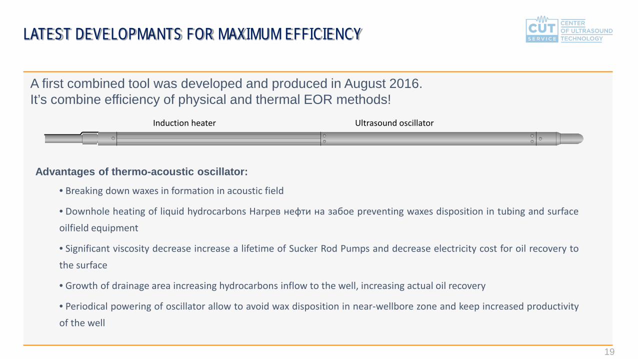
A first combined tool was developed and produced in August 2016. It’s combine efficiency of physical and thermal EOR methods!
Advantages of thermo-acoustic oscillator:
• Breaking down waxes in formation in acoustic field
• Downhole heating of liquid hydrocarbons Нагрев нефти на забое preventing waxes disposition in tubing and surfaceoilfield equipment
• Significant viscosity decrease increase a lifetime of Sucker Rod Pumps and decrease electricity cost for oil recovery tothe surface
• Growth of drainage area increasing hydrocarbons inflow to the well, increasing actual oil recovery
• Periodical powering of oscillator allow to avoid wax disposition in near-wellbore zone and keep increased productivityof the well
Induction heater Ultrasound oscillator

20
Continuous AWS is intended to increase the flowrate of heavy oil
The device is installed during workover operations on the well
Downhole tool with diameter 102 mm is attached to the tubing
Downhole tool remains in the well and operating periodically
Device is controlled by ultrasonic generator from the surface
Treatment efficiency can be enhanced by chemical injection into
the treatment zone or using different frequencies
We are offering 3 main types of services:
Continuous AWS
Continuous AWS with injection of chemicals
(own chemicals developed and patented)
Continuous AWS in combination with heating
1 – Anchor2 – Generator3 – Downhole device4 – Casing5 – Tubing6 – Formation7 – AWS treatment zone8 – Perforation interval9 – Cable
AWS SERVICES FOR WELLS WITH HEAVY AND VISCOUS OIL
21
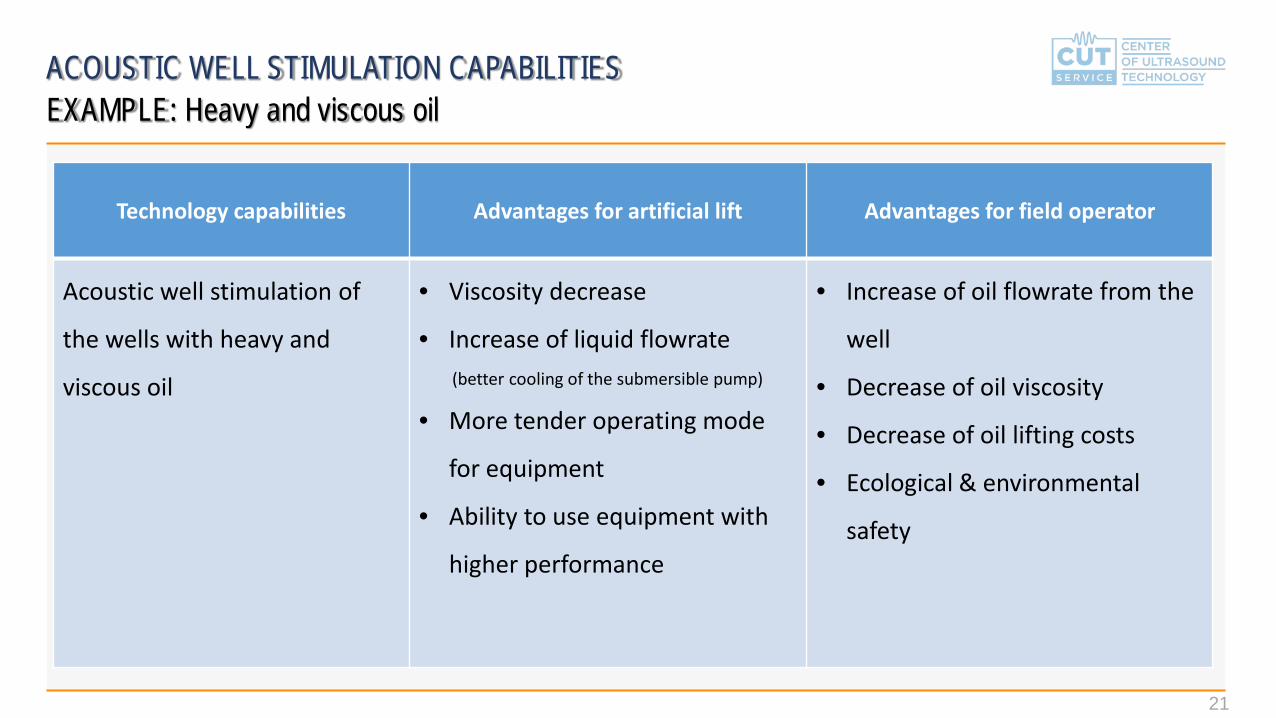
ACOUSTIC WELL STIMULATION CAPABILITIESEXAMPLE: Heavy and viscous oil
Technology capabilities Advantages for artificial lift Advantages for field operator
Acoustic well stimulation of
the wells with heavy and
viscous oil
• Viscosity decrease
• Increase of liquid flowrate(better cooling of the submersible pump)
• More tender operating mode
for equipment
• Ability to use equipment with
higher performance
• Increase of oil flowrate from the
well
• Decrease of oil viscosity
• Decrease of oil lifting costs
• Ecological & environmental
safety

22
ACOUSTIC WELL STIMULATION CAPABILITIESEXAMPLE: Heavy and viscous oil
PCP + AWS ESP + AWSSRP + AWS
Operating experience:• Russia: Republic of Tatarstan
• USA
Operating experience:• Canada
Ongoing development

23
CEMENT-FRIENDLY TREATMENT, PROVEN ON PRACTICE
The experiments on the impact of ultrasound onsamples of cement (conducted using thestandard method ГОСТ 1581-96 on the deviceМИИ-100) confirmed, that ultrasound with theintensity 10 times higher than the intensity ofused during treatment of wells don’t affect theintegrity of the cement
№ of the sample set
Pressure, atm
Temperature, 0С
Time of ultrasonic treatment, hrs
Bending strength, kGs/cm2
1 1 20 Not 5,25
2 90 80 2 5,26
3 90 80 4 5,25 Samples before and after the experiments
Photograph and scheme of the experimental equipment used to check the impact of ultrasound on the cement under high pressure and temperature

24
PHYSICAL PROPERTIES OF
ULTRASONIC EXPOSURE
25
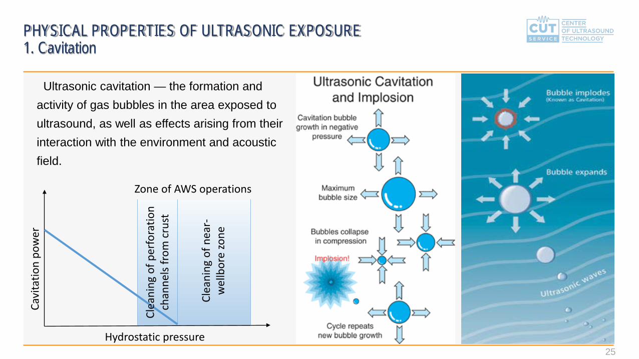
Ultrasonic cavitation — the formation and activity of gas bubbles in the area exposed to ultrasound, as well as effects arising from their interaction with the environment and acoustic field.
PHYSICAL PROPERTIES OF ULTRASONIC EXPOSURE1. Cavitation
Hydrostatic pressure
Cavi
tatio
n po
wer
Zone of AWS operations
Clea
ning
of p
erfo
ratio
n ch
anne
ls fr
om c
rust
Clea
ning
of n
ear-
wel
lbor
e zo
ne

26
If the liquid in the capillary tube oscillates under the influence of the source of ultrasound, the capillary effect increases dramatically: the height of the liquid column increases several tens of times significantly increases the speed of recovery. Experimentally proven that the fluid is pushing up not by the radiation pressure and the capillary force, but by a standing ultrasonic wave. The ultrasound again and again compress the liquid column and picks it up.
(Discovered by academician E. G. Konovalov, 1961)
PHYSICAL PROPERTIES OF ULTRASONIC EXPOSURE2. Sono-capillary effect

27
During AWS each molecule of liquid is exposed to time-dependent tension:
PHYSICAL PROPERTIES OF ULTRASONIC EXPOSURE3. Destruction of intermolecular bonds
Acoustic field
resinous-asphaltenicmaterial
Acoustic field
resinous-asphaltenicmaterial
Afte
r AW
SBe
fore
AW
S
σ(t) = σ0 sinωt
Legend: σΤ – breaking stress for current type of intermolecular bonds, γ – characteristic for current type of intermolecular bonds, K – Boltsman constant, Т – temperature.
If the exposure duration exceeds the time, then there is a rupture of intermolecular bonds
−=0
T
00
T
σσln
γσkT
σσ
pNτр = Np /ω;

28
PHYSICAL PROPERTIES OF ULTRASONIC EXPOSURESUMMARY
Physical property Cavitation Sono-capillary effect Destruction of intermolecular bonds
Application Cleaning of perforation channels Heavy oil Cleaning of near-
wellbore zone
Principle of impactDetaching crust from
boundary of perforation channel
Increase speed of inflow from pores in formation
and lead to increase drainage area of the well
Decrease of skin effect by breaking boundary
layer on mud filtrate and other foreign particles
that lead to easy removal of such particles from
formation pores
Specific notes Serious requirements to cement quality
For permanent applications
For temporary treatmentduring workover
operations

29
COMBINATION WITH EXISTED METHODS OF ENHANCED OIL RECOVERY EFFECTIVE TREATMENT ON WELLS WITH LOW AND ZERO FLOWRATES ABSENCE OF NEGATIVE EFFECT TO ENVIRONMENT AND FORMATION RUSSIAN DEVELOPMENT AND LOCAL MANUFACTURING HIGH PERFORMANCE INDICATOR OF TREATMENTS MAXIMUM GENERATED POWER UP TO 10 KW COMPACT EQUIPMENT AND MOBILE TEAMS UNLIMITED ITERATIONS ON EACH WELL NO DAMAGE TO CEMENT OR CASING A STRONG SCIENTIFIC BACKGROUND HIGH PERFORMANCE ON HEAVY OIL
TECHNOLOGY ADVANTAGES

30
CONFIFMATION OF EFFICINCY

31
More than 100 wells treated during period from 2011 till 2013 on the territory of Russian Federation: Average oil production growth – from 4,2 m3/day to 8,4 m3/day (100%) Success rate 90% Duration of effect from 6 to 24 month
Average results of treatment for one of Clients in Western Siberia:
Liquid and oil flowrate history Commercial effect, cumulative (mln.rub)
Continuous effect over 1 year
CONFIRMATION OF EFFICIENCY ON LIGHT OILTreatments in 2011-2013
32
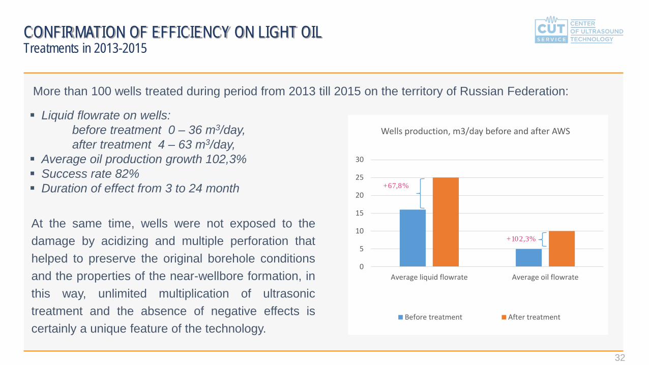
0
5
10
15
20
25
30
Average liquid flowrate Average oil flowrate
Wells production, m3/day before and after AWS
Before treatment After treatment
More than 100 wells treated during period from 2013 till 2015 on the territory of Russian Federation:
Liquid flowrate on wells:before treatment 0 – 36 m3/day,after treatment 4 – 63 m3/day,
Average oil production growth 102,3% Success rate 82% Duration of effect from 3 to 24 month +67,8%
+102,3%
CONFIRMATION OF EFFICIENCY ON LIGHT OILTreatments in 2013-2015
At the same time, wells were not exposed to thedamage by acidizing and multiple perforation thathelped to preserve the original borehole conditionsand the properties of the near-wellbore formation, inthis way, unlimited multiplication of ultrasonictreatment and the absence of negative effects iscertainly a unique feature of the technology.

33
CONFIRMATION OF EFFICIENCY ON LIGHT OIL Treatments in 2012
№ Client Oilfoeld Well numer BEFORE TREATMENT AFTER TREATMENT EFFECT EVALUATION
Qliq, m3/day Qoil, ton/day % w/c Dynamic liquid level Qliq, m3/day Qoil, ton/day % w/c Dynamic
liquid levelQliq, m3/day
(+/-)Qoil, ton/day
(+/-)Qoil, difference,
%% w/c(+/-)
Dynamic liquid level (+/-)
1 Samotlorneftegaz Samotlorskoe Confidential 32,0 4,8 82,0 1463,0 40,0 8,4 75,0 1477,1 8,0 3,6 75% -7,0 -14,12 Samotlorneftegaz Samotlorskoe Confidential 18,0 2,7 82,0 1440,0 20,0 3,0 82,0 1216,0 2,0 0,3 11% 0,0 224,03 Samotlorneftegaz Samotlorskoe Confidential 21,0 2,5 86,0 1473,0 20,0 3,0 82,0 1321,9 -1,0 0,6 24% -4,0 151,14 Samotlorneftegaz Samotlorskoe Confidential 35,0 4,4 85,0 1307,0 60,0 26,2 48,0 1428,7 25,0 21,8 495% -37,0 -121,75 Samotlorneftegaz Samotlorskoe Confidential 14,0 4,4 63,0 1370,0 50,0 11,8 72,0 1324,0 36,0 7,4 168% 9,0 46,06 Samotlorneftegaz Samotlorskoe Confidential 13,0 6,6 40,0 1947,0 23,0 7,3 62,0 1645,2 10,0 0,8 12% 22,0 301,87 Samotlorneftegaz Samotlorskoe Confidential 24,0 2,6 87,0 1025,0 46,0 12,4 68,0 1293,1 22,0 9,7 373% -19,0 -268,18 Samotlorneftegaz Samotlorskoe Confidential 7,0 4,6 22,0 1604,0 22,0 13,9 25,0 1529,0 15,0 9,3 202% 3,0 75,09 Samotlorneftegaz Samotlorskoe Confidential 12,0 2,2 78,0 1643,0 12,0 2,2 78,0 1603,5 0,0 0,0 0% 0,0 39,5
10 Samotlorneftegaz Samotlorskoe Confidential 26,0 2,2 90,0 1694,0 22,0 3,7 80,0 1345,1 -4,0 1,5 68% -10,0 348,911 Samotlorneftegaz Samotlorskoe Confidential 25,0 6,1 71,0 990,0 49,0 10,3 75,0 1188,2 24,0 4,2 69% 4,0 -198,212 Samotlorneftegaz Samotlorskoe Confidential 8,0 5,2 22,0 1277,0 10,0 5,4 36,0 1115,5 2,0 0,1 2% 14,0 161,513 Samotlorneftegaz Samotlorskoe Confidential 17,0 2,9 80,0 1627,0 22,0 2,8 85,0 1596,4 5,0 -0,1 -3% 5,0 30,614 Samotlorneftegaz Samotlorskoe Confidential 16,0 2,7 80,0 1353,0 25,0 5,5 74,0 1462,0 9,0 2,8 104% -6,0 -109,015 Samotlorneftegaz Samotlorskoe Confidential 22,0 4,4 76,0 1355,0 36,0 7,6 75,0 1288,4 14,0 3,1 70% -1,0 66,616 Samotlorneftegaz Samotlorskoe Confidential 18,7 2,0 87,5 1656,0 18,0 3,0 80,0 1426,5 -0,7 1,1 55% -7,5 229,517 Samotlorneftegaz Samotlorskoe Confidential 37,0 3,4 89,1 1249,0 57,0 4,8 90,0 1199,1 20,0 1,4 41% 0,9 49,918 Samotlorneftegaz Samotlorskoe Confidential 13,0 3,5 68,3 1584,5 15,0 7,6 40,0 1553,9 2,0 4,1 117% -28,3 30,619 Samotlorneftegaz Samotlorskoe Confidential 30,0 5,0 80,0 895,0 74,0 9,9 84,0 1328,6 44,0 4,9 98% 4,0 -433,620 Samotlorneftegaz Samotlorskoe Confidential 17,0 2,4 83,0 1229,0 18,0 1,5 90,0 1570,2 1,0 -0,9 -38% 7,0 -341,221 Samotlorneftegaz Samotlorskoe Confidential 36,0 3,0 90,0 1295,0 57,0 15,8 67,0 1367,5 21,0 12,8 427% -23,0 -72,522 Samotlorneftegaz Samotlorskoe Confidential 33,0 4,2 85,0 877,0 50,0 7,6 82,0 1329,2 17,0 3,4 81% -3,0 -452,223 Samotlorneftegaz Samotlorskoe Confidential 17,0 2,6 82,0 1252,0 33,0 5,0 82,0 1309,2 16,0 2,4 92% 0,0 -57,224 Samotlorneftegaz Samotlorskoe Confidential 9,0 2,0 74,0 1351,0 11,0 2,8 70,0 1580,9 2,0 0,8 40% -4,0 -229,925 Samotlorneftegaz Samotlorskoe Confidential 10,0 2,1 75,0 1648,0 15,0 6,2 51,0 1604,2 5,0 4,1 195% -24,0 43,826 Samotlorneftegaz Samotlorskoe Confidential 18,0 2,3 85,0 1550,0 18,0 2,3 85,0 1573,4 0,0 0,0 0% 0,0 -23,427 Samotlorneftegaz Samotlorskoe Confidential 32,0 6,7 75,0 1236,0 48,0 12,1 70,0 1376,5 16,0 5,4 81% -5,0 -140,528 Samotlorneftegaz Samotlorskoe Confidential 8,0 6,4 5,0 1858,0 6,0 4,9 3,0 1556,7 -2,0 -1,5 -23% -2,0 301,329 Samotlorneftegaz Samotlorskoe Confidential 32,0 9,1 66,0 1733,0 52,0 16,6 62,0 1587,3 20,0 7,5 82% -4,0 145,730 Samotlorneftegaz Samotlorskoe Confidential 20,0 3,4 80,0 1772,0 33,0 6,9 75,0 1440,1 13,0 3,6 106% -5,0 331,9
AVERAGE for Samotlorneftegaz 20,7 3,9 72,3 1425,1 32,1 7,7 68,3 1421,2 11,4
(+ 55%) 3,8 98% -4,0 3,9
31 Samaraneftegaz Vetlyanskoe Confidential 36,0 10,0 66,0 1310,0 48,0 13,0 67,7 1690,0 12,0 3,0 30% 1,7 -380,0
32 Samaraneftegaz Sofyinsko-Dzerzhinskoe Confidential 22,0 6,0 68,8 1652,0 37,0 10,0 67,0 1729,0 15,0 4,0 67% -1,8 -77,0
33 Samaraneftegaz Solotskoe Confidential 48,0 14,0 65,0 1711,0 75,0 39,5 38,0 1207,0 27,0 25,5 182% -27,0 504,0AVERAGE for
Samaraneftegaz 35,3 10,0 66,6 1557,7 53,3 20,8 57,6 1542,0 18,0(+ 51%) 10,8 108% -9,0 15,7
TOTAL AVERAGE for 2012 22,0 4,4 71,8 1436,8 33,9 8,8 67,3 1431,9 12,0
(+55%) 4,4 100% -4,5 4,9
34
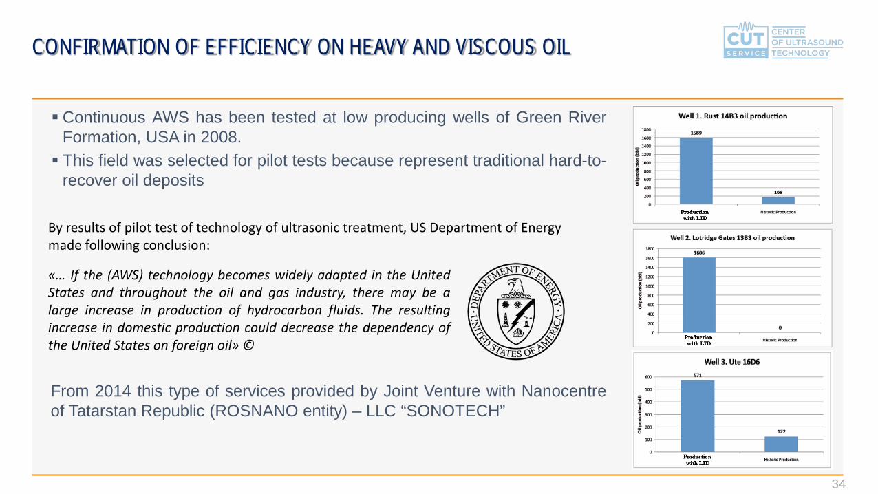
Continuous AWS has been tested at low producing wells of Green RiverFormation, USA in 2008. This field was selected for pilot tests because represent traditional hard-to-
recover oil deposits
From 2014 this type of services provided by Joint Venture with Nanocentreof Tatarstan Republic (ROSNANO entity) – LLC “SONOTECH”
CONFIRMATION OF EFFICIENCY ON HEAVY AND VISCOUS OIL
By results of pilot test of technology of ultrasonic treatment, US Department of Energy made following conclusion:
«… If the (AWS) technology becomes widely adapted in the UnitedStates and throughout the oil and gas industry, there may be alarge increase in production of hydrocarbon fluids. The resultingincrease in domestic production could decrease the dependency ofthe United States on foreign oil» ©

35
Outstanding results on extra-low rates heavy oil wells in Canada in 2016
Date
12.0
4.20
16
19.0
4.20
16
26.0
4.20
16
03.0
5.20
16
10.0
5.20
16
11.0
5.20
16
12.0
5.20
16
13.0
5.20
16
17.0
5.20
16
Average daily flowrate, bbl/dayWell #1 1,08 1,00 0,71 0,71 0,86 7,00 3,00 2,00 1,25Well #2 1,00 0,57 0,00 0,00 0,86 5,00 3,00 1,00 0,75Well #3 1,00 0,71 0,71 0,71 0,86 1,00 1,50 2,00 1,00Well #4 0,83 0,71 0,71 0,71 0,86 6,50 5,50 5,00 1,25
--> <-- AWS treatment
Relative productivity growth
Days after treatment -> 0 1 2 3 7Well #1 100% 817% 350% 233% 146%
Well #2 100% 583% 350% 117% 88%
Well #3 100% 117% 175% 233% 117%
Well #4 100% 758% 642% 583% 146%
Instant productivity growth > 800%Effect duration – up to 7 days
Single stimulation proved that installation of oscillators for continuous operations will allow to keep productivity rate at level of 700-800% from initial and will require to power up oscillators just for 30 minutes daily
Project status: ongoing discussions on Phase 2 details – introduction of AWS equipment for permanent installation
CONFIRMATION OF EFFICIENCY ON HEAVY AND VISCOUS OIL

36
SC «ТАТЕХ», Republic of Tatarstan, Russian Federation
Treatment of 2 wells of Demkinskoe field in 2015:
Trial job proved technology efficiency in the formation conditions
On Well #1 equipment was removed after the treatmentOn Well #2 equipment kept in the well for the continuous monitoring for 1 year
Project status: ongoing selection of 3-5 wells for the treatment with thermo-acoustic oscillator in 2017.
CONFIRMATION OF EFFICIENCY ON HEAVY AND VISCOUS OIL
Descroption WELL 1 WELL 2
Instant oil flowrate growth + 15% + 30%
Effect duration 3 days 3 days
Recognition letter:

37
CONFIRMATION OF EFFICIENCY Recognition letters
Technology went through all levels of
field trials from 2010 until 2012 and was
added to the list of priority technologies
to deployment in TNK-BP by HQ
Management.
From 2012 technology fully
commercialized in Russian Federation

38
QUESTIONS