
Acoustic Scaling of Axial Fan
11
752 SM International Jou rnal VoL 13 No 10 752-761 1999 Acoustic Scaling o f an Axial Fan with Non-Uniform Inlet Flows Seungbae Lee* and Gwi-Chul Yang** Received December 28, 1998) An experimental study was carried out to vary circumferential and radial components of incoming disturbances for a propeller-type axial fan connected to an anechoically terminated inlet duct. was suggested that the acoustic pressure from rotating blades encountering a low -frequent gust have the scaling parameter of poCo I I a while the one for a high-frequent gust be properly sca ed by poCo 1 I . Here PoCo I Ma are the characteristic impedance of medium, the amplitude of dist urbed velocity, and Ma ch number, respec tively. These scalings were applied to identify both compact and non-compact noise sources from low-frequent gusts using the spectral decomposition metho . The method of acoustic scaling proposed in this study turned ou t to be more effective for the sound radiated into a duct by the interaction of low-frequent incoming gusts with the propeller fan than previous approaches. Key Words: Propeller-Type Axial Fan, Noise, Acoustic Scaling, Spectral Decomposition 1. Introduction This paper is concerned with noise generated by an axial fan with non-uniform inlet flows. Th e propeller-type axial fans have been increasingly utilized in home appliances for the convective cooling, e. g. in air-conditioning units. The non uniform inlet flows by unavoidable obstacles located upstream often generate increased tonal noise. Recently, the spatial compactness becomes inherent with the growing width of application of the propeller-type axial fan. Consequently, non -uniform flows are frequently encountered at a blade inlet and result in a significant increase in the discrete frequency sound level. This type of unsteady lifting surface problem is known as a gust problem in marine/aerodynamic applica tions or called as an inlet distortion in turboma chines. Th e problem of propeller-gust interaction has been treated recently by a semi-analytical • Department of Mechanic al Engineering, INHA Uni versity, 253 Yonghyun dong Nam-gu, Incheon 402 751, KOREA •• Graduate Student, Flow Noise Control Laboratory, INHA University, Incheon 402-751. KOREA method(Attasi et aI., 1990). Th e F an Sound Law attempted by Madison in 1949 ha been the subject o f considerable speculati on and controversy. Th e tip speed expo nent for the sound power ranges from 4.6 to 6.0 even or the discrete frequency sound. Weidemann (1971) decomposed the radiated sound from the uncased centrifugal impellers with a rectangular wedge into a normalized spectral distribution function and an acoustic frequency response function. Following Weidemann s for mulation of the similarity law, Neise (1975) per formed a similar experiment for the two dimen sionally similar centrifuga fans with identical impellers to those of Weidemann. He measured a value of 4.6 different from 5.6 by Weidemann for the impeller tip speed exponent o f sound power. Th e discrepancy in the V-dependence of sound law was also observed by Longhouse(l976), who examined the rotational noise for the inflow distortion and turbulence y installing the circu lar rods upstream for a low tip-speed axial fan. He explained the discrepancy by the reason that the inflow distortion and turbulence may not increase in direct proportional to the tip speed. Margetts(1987) demonstrated that the equivalent acoust c source from an axial fan is of a dipole
-
Upload
joseph-alexander-borg -
Category
Documents
-
view
223 -
download
0
Transcript of Acoustic Scaling of Axial Fan
8/11/2019 Acoustic Scaling of Axial Fan
http://slidepdf.com/reader/full/acoustic-scaling-of-axial-fan 1/10
752
SM
International Journal VoL
13
No 10 752-761 1999
Acoustic Scaling
of
an Axial Fan with
Non-Uniform
Inlet Flows
Seungbae Lee* and
Gwi-Chul
Yang**
Received December 28, 1998)
An experimental study was carried out to vary circumferential and radial components of
incoming disturbances for a propeller-type axial fan connected to an anechoically terminated
inlet duct. was suggested that the acoustic pressure from rotating blades encountering a low
-frequent gust have the scaling parameter of
poCo
I I
a
while the one for a high-frequent gust
be properly scaled by
poCo
1 I.Here
PoCo
I Ma are the characteristic impedance of medium,
the amplitude of disturbed velocity, and Mach number, respectively. These scalings were applied
to identify both compact and non-compact noise sources from low-frequent gusts using the
spectral decomposition method. The method of acoustic scaling proposed in this study turned
out
to be more effective for the sound radiated into a duct by the interaction of low-frequent
incoming gusts with the propeller fan than previous approaches.
Key
Words:
Propeller-Type Axial Fan, Noise, Acoustic Scaling, Spectral Decomposition
1. Introduction
This paper is concerned with noise generated
by an axial fan with non-uniform inlet flows. The
propeller-type axial fans have been increasingly
utilized in home appliances for the convective
cooling, e. g. in air-conditioning units. The non
uniform inlet flows by unavoidable obstacles
located upstream often generate increased tonal
noise.
Recently, the spatial compactness becomes
inherent with the growing width of application of
the propeller-type axial fan. Consequently, non
-uniform flows are frequently encountered at a
blade inlet and result in a significant increase in
the discrete frequency sound level. This type of
unsteady lifting surface problem is known as a
gust problem in marine/aerodynamic applica
tions or called as an inlet distortion in turboma
chines.
The
problem of propeller-gust interaction
has been treated recently by a semi-analytical
• Department of Mechanical Engineering,
INHA
Uni
versity, 253 Yonghyun dong Nam-gu, Incheon 402
751, KOREA
•• Graduate Student, Flow Noise Control Laboratory,
INHA
University, Incheon 402-751. KOREA
method(Attasi et aI., 1990).
The
Fan Sound Law attempted by Madison
in 1949 has been the subject of considerable
speculation and controversy.
The
tip speed expo
nent for the sound power ranges from 4.6 to 6.0
even for the discrete frequency
sound.
Weidemann (1971) decomposed the radiat ed
sound from the uncased centrifugal impellers with
a rectangular wedge into a normalized spectral
distribution function and an acoustic frequency
response function. Following Weidemann s for
mulation of the similarity law, Neise (1975) per
formed a similar experiment for the two dimen
sionally similar centrifugal fans with identical
impellers to those of Weidemann. He measured a
value
of
4.6 different from 5.6 by Weidemann for
the impeller tip speed exponent of sound power.
The discrepancy in the V-dependence
of
sound
law was also observed by Longhouse(l976), who
examined the rotational noise for the inflow
distortion and turbulence by installing the circu
lar rods upstream for a low tip-speed axial fan.
He explained the discrepancy by the reason that
the inflow distortion and turbulence may not
increase in direct proport ional to the tip speed.
Margetts (1987) demonstrated that the equivalent
acoustic source from an axial fan is of a dipole

8/11/2019 Acoustic Scaling of Axial Fan
http://slidepdf.com/reader/full/acoustic-scaling-of-axial-fan 2/10
coustic Scaling
of
an
x i l
Fan with Non Uniform Inlet Flows
7
nature from the measurement
of
phases from inlet
and outlet noise. But his elaborate measurement
of
dipole source does not explain the departure of
a speed scal ing index over a range of speeds and
with a range of
duct lengths.
The idea
of
discrete source identif ication in
turbomachinery using the spectral decomposition
method was extended by Mongeau et al. (1993) to
investigate the relatively low frequency aer
odynamic source of rotating stall and broadband
noise sources.
The
dynamic pressure, V ~ P and
the rotational time of D /V
tl P
were used to scale
the acoustic pressure and the characteristic time of
acoustic correlation in their spectral decomposi
tion method. It did not include the effect of
acoustic impedance upon radiation from impel
lers installed in the duct.
Their
effects were natu
rally thrown into the source spectral distribution
function, which is not supposed to affect sound
radiation efficiency.
As was discussed by Neise (1975), there might
be no hope for finding a universal value for the
impeller tip speed exponent. But the source identi
fication methods, which can be implemented with
ease, are now sought
and
the spectral decomposi
t ion method is one
of
the candidates for assessing
fan noise source characteristics.
For
this purpose,
the scaling parameters of an acoustic pressure
spectral density function need to be re-examined
on the physical
ground
of order of magnitude
analysis for non uniform incoming flows. In the
present work, flow conditioners designed to intro
duce non uniformity to the flow were installed in
an acoustically lined duct. Experiments were
conducted using a prope ller-type axial fan dis
charging directly into the atmosphere in order to
investigate the noise source characteristics for
non uniform
inlet flows. The objective of this
study is to develop acoustic scaling parameters for
inflow distortions of low-frequent gusts and iden
tify each noise source characteristics for various
non uniform inlet conditions.
2 Mathematical Background of
Scaling Parameters
There are two approaches to the study of aer
oacoust ics (Goldstein, 1976): one is to directly
solve a set of linearized governing equations
specifically for
sound
generation due to the pres
sure fluctuations on a solid
boundary
in a moving
medium, the other is to follow the Lighthill s
acoustic analogy (1952) deduced from governing
equations. Based on Lighthi ll s theory, Ffowcs
Williams and Hawkings (1969) have established a
more general aeroacoust ic theory for a moving
solid boundary in a non stationary medium. Here
we follow the Goldstein s approach to scale the
noise generated by the rotating fan blades.
The non uni form inlet flow
of
approaching
gusts to a rotat ing blade can be classified into a
high-frequent gust problem and low-frequent one
depending on a characteristic time-scale involved.
If the characteristic time-scale of
harmonic distur
bance of incoming gusts in the blade frame
of
reference is of comparable magnitude with an
acoustic time-scale, this may be called as a high-
frequent gust problem. The low-frequent gust
problem specifies that the characteristic time
scale involved in the noise generat ion is longer
than
the acoustic traveling time-scale as shown in
Table
Table Classifications using terminologies in this study for non-uniform inlet flows and non-uniform
inflow turbulence noise.
Non uniform
inlet
High-frequent gust
p .n
-i (gust frequency: ) -ro/co(acoustic time-scale)
flow of incoming gust
Low-frequent gust p .n
o
)
i ~ r o / c o a c o u s t i c time-scale)
Compact source
(size of eddy)
(blade chord length)
Non-uniform inflow
(low frequency noise)
turbulence noise Non-compact source
(high frequency noise)
(size of eddy) <t:C (blade chord length)
8/11/2019 Acoustic Scaling of Axial Fan
http://slidepdf.com/reader/full/acoustic-scaling-of-axial-fan 3/10
754
Seungbae Lee n Gwi Chul Yang
(4)
The non-uniform inflow-turbulence noise can
be classified into low-frequency and high fre
quency inflow noise, depending on whether the
length of disturbance is longer than the blade
chord or not.
If
the size
of
eddy is much bigger
than the chord of blade, the blade will experience
a fluctuation of total lift as a whole. This situa
tion occurs in the atmospheric turbulence noise
from the wind turbine causing sound radiation of
Ma
6
because the blade can be regarded to be
acoustically compact. In the other case of small
sized eddy comparable or less than the dimension
of blade, the blade will respond only locally and
radiate sound scattered at the leading and trailing
edges varying with Ma {Ffowcs Williams et al.,
1970 .
The
present paper is concerned with the
effects
of
both non-compact sources of high fre
quency and compact sources of low-frequency
inflow turbulence upon radiated sound for the
low-frequent gust problem.
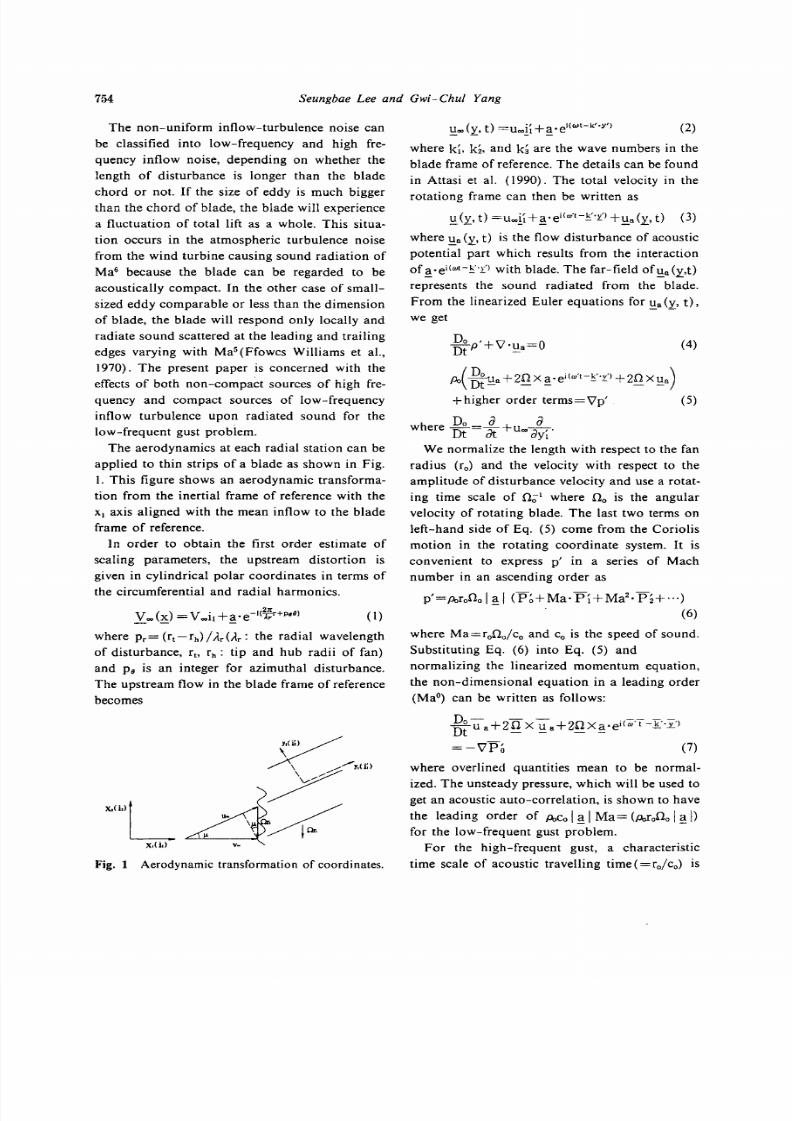
The aerodynamics at each radial station can be
applied to thin strips of a blade as shown in Fig.
l. This figure shows an aerodynamic transforma
tion from the inertial frame of reference with the
Xl axis aligned with the mean inflow to the blade
frame of reference.
In order to ob tain the first order estimate
of
scaling parameters, the upstream distortion is
given in cylindrical polar coordinates in terms of
the circumferential and radial harmonics.
I)
where
Pr=
r t-r
h
/
tlrC 1r:
the radial wavelength
of disturbance, r., r
h
:
tip and hub radii
of
fan)
and P8 is an integer for azimuthal disturbance.
The upstream flow in the blade frame of reference
becomes
Fig. 1 Aerodynamic transformation of coordinates.
(2)
where ki, k
z,
and k
3
are the wave numbers in the
blade frame of reference. The details can be found
in Attasi et al.
1990 .
The total velocity in the
rotationg frame can then be written as
:
(y, t) =ucoii ~ · e i w · t - ~ · · t ) + : .a
:i.
t (3)
where : .a y, t is the flow disturbance of acoustic
potential part which results from the interaction
of ~ e i ( w t - ~ r ) with blade. The far-field of : .a y,t)
represents the sound radiated from the blade.
From the linearized Euler equations for
: .a
y,
t) .
we get
g ~ P + V : . a = O
o D O U a + 2 n x a · e i W t - ~ , · t ) +2nxua)
Dt - - - -
+higher order terms=Vp (5)
h
Do
a
were
15 t=a t
u
co
oy
We normalize the length with respect to the fan
radius (r
o
and the velocity with respect to the
amplitude of disturbance velocity and use a rotat
ing time scale of 0
0
1
where no is the angular
velocity of rotating blade. The last two terms on
left-hand side
of
Eq.
(5)
come from the Coriolis
motion in the rotating coordinate system. It is
convenient to express p in a series
of
Mach
number in an ascending order as
p = P o r o O o l ~ 1
P ~ + M a · P i + M a 2 · P z + · , ,
(6)
where Ma=rono/c
o
and Co is the speed of sound.
Substituting Eq. 6 into Eq. 5 and
normalizing the linearized momentum equation,
the non-dimensional equation in a leading order
(MaO) can be written as follows:
DoUa +2
n X Ua
--zn
X
a ei{m T
-
: .i: )
Dt - -
= V p ~ 7
where overlined quantities mean to be normal
ized.
The
unsteady pressure, which will be used to
get an acoustic auto-correlation, is shown to have
the leading order of
o o
I ~ I
Ma=
(PoroOo
I ~
for the low-frequent gust problem.
For
the high-frequent gust, a characteristic
time scale of acoustic travelling time =ro/c
o
is
8/11/2019 Acoustic Scaling of Axial Fan
http://slidepdf.com/reader/full/acoustic-scaling-of-axial-fan 4/10
coustic Scaling
of
an
x i l
Fan with Non Uniform Inlet Flows
755
Physical Characteristics
3 Experimental Procedure
Table Physical properties of the axial-type
propeller fan.
An experimental device, shown schematically
in Fig. 2 was installed in an anechoic chamber of
f<
1 ~
1
Ma
2
b ~
1380Hz
8
The acoustically lined duct also eliminates the
problem of radial s tanding mode in the test duct
at the low frequency range
of
interests.
The duct used in this study introduces very
uniform flow with low turbulence levels to the
rotating blades by using the combination of
honey-comb and two screens of 32-mesh size. An
anechoic termination is installed upstream of the
test section to minimize the effect of an axial
standing wave and to provide an acoustic loading
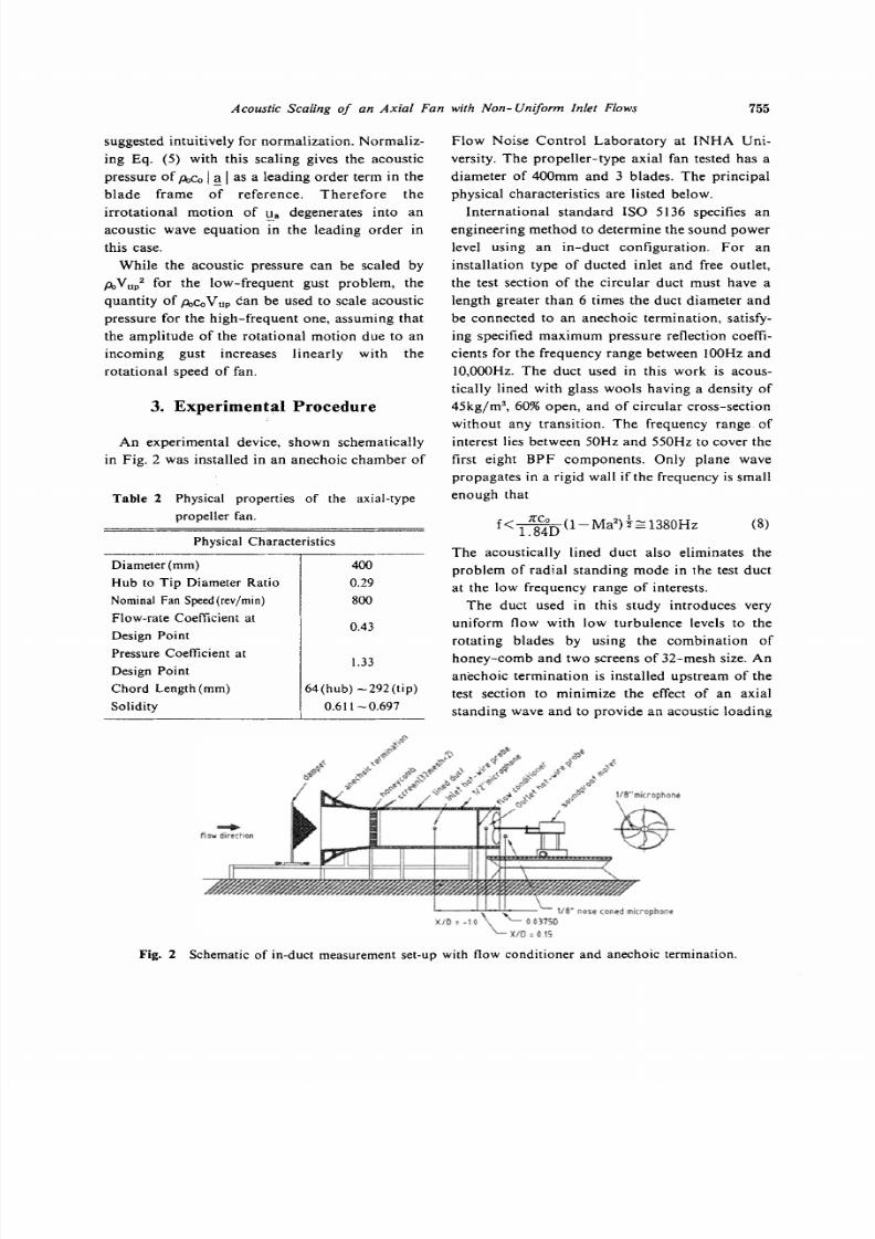
Flow Noise Control Laboratory at INHA Uni
versity. The propeller-type axial fan tested has a
diameter of 400mm and 3 blades. The principal
physical characteristics are listed below.
International standard ISO 5136 specifies an
engineering method to determine the sound power
level using an in-duct configuration. For
an
installat ion type of ducted inlet and free outlet,
the test section of the circular duct must have a
length greater than 6 times the duct diameter and
be connected to an anechoic termination, satisfy
ing specified maximum pressure reflection coeffi
cients for the frequency range between 100Hz and
IO OOOHz.
The duct used in this work is acous
tically lined with glass wools having a density of
45kgjm
3
, 60 open, and of circular cross-section
without any transition. The frequency range of
interest lies between 50Hz and 550Hz to cover the
first eight BPF components. Only plane wave
propagates in a rigid wall if the frequency is small
enough that
33
0.43
400
0.29
800
64 hub) -292 tip
0.611-0.697
Diameter mm)
Hub to Tip Diameter Ratio
Nominal Fan Speedtrev/min)
Flow-rate Coefficient at
Design Point
Pressure Coefficient at
Design Point
Chord Length mm)
Solidity
suggested intuitively for normalization. Normaliz
ing Eq. 5) with this scaling gives the acoustic
pressure
of o o
I I
as a leading order term in the
blade frame of reference. Therefore the
irrotational motion
of
a degenerates into an
acoustic wave equation in the leading order in
this case.
While the acoustic pressure can be scaled by
o
V
u
/
for the low-frequent gust problem, the
quantity of
o o
V
up
can be used to scale acoustic
pressure for the high-frequent one, assuming that
the amplitude of the rotational motion due to an
incoming gust increases linearly with the
rotational speed of fan.
flow direction
118 nese
conedmi,r,pnont
0031S0
X/O
,01S
Fig Schematic of in-duct measurement set-up with flow conditioner and anechoic termination.
8/11/2019 Acoustic Scaling of Axial Fan
http://slidepdf.com/reader/full/acoustic-scaling-of-axial-fan 5/10
7
Seungbae Lee
and Gwi
Chu/ Yang
4. Measured Spectra
and
Spectral
Decomposition
01
0'
14
11
I-.-
Tested Fan
I
20
6
Z
.
•
,
I .
<,
B-
12
.
I
.
10
_ _ • _
e _ _ •
t
O'
--,--
O'
O'
.
0 2
velocity and turbulent intensity downstream of
the flow conditioner, an
I-type
hot-w ire sensor is
traversed across the duct cross -section.
0 4
os
De
et>
I (NO )
Fig. 4 Performancecurve ofpropeller fan employed.
The aerodynamic performance of the propeller
fan is first measured by following the standard by
ANSI / AMCA210-85. The non-d imensional
pressure coefficients
lJf=t::.p/
p
2
» for the
propeller fan tested are drawn with respect to the
non-dimensional flow-rate 1 =Q/
(ND
3
» in
Fig. 4. The units used in non-dimensional param
eters are m
3
/sec,
tev]»
meter, Pascal, kg/rn for
Q,
N, 0, t p
and
p
respectively .
The flow conditioner is located at a short
distance (0
.150
upstream of the fan . Figure 5
shows the measured mean axial velocity distribu
tions for radially slot ted flow conditioners. The
loading condit ions are set to have a flow coeffi
cient close to 0.35 regardless of the type of flow
on the blades nearly equal to the characteristic
impedance of the air. The test duct
of
a short
length also makes the growth of a boundary layer
to be confined, which is important to generat ing
specified non-uniform inlet flows. When the
Reynolds number based on the duct diameter is
about 10
5
, the entrance length is about 30 times of
that which is comparable with the length of
the
test duct for a standard in-duct method. There
fore it is desirable for this purpose to have a test
duct
of
a
short
length unless resonance may occur.
Upstream of the propel ler fan is located a flow
conditioner designed to generate circumferential
and radial components of
non-uniform
incoming
flow. Figure 3 shows the slotted flow conditioners
for the azimuthal and radial disturbances. The
mechanical apparatus driving the propeller fan
consists of a shaft, a bearing assembly and an
adapter . A one kilowatt O. C. motor is controlled
to vary the shaft ro tational speed and covered by
5mm thick steel wall with glass wools filled
inside. The shaft speed of the motor is measured
using an encoder device sending 3600 pulses per
one revolution. A microphone of Brilel Kjar
1/2 size is mounted flush with the inlet duct wall
and a B&K 1/8 pressure-type microphone with a
nose-cone is located
just
downstream
of
the
propel ler fan for the cross-spectrum measure
ments. To measure the distributions of
mean axial
(a) Circumferent ia l no w c
ondit
i
oner
s
10
'
2
..0-'
_ 1 . e .- 0 _
....
: $. C t O oW.
- . . - SJC ..-0 1
~ S
•
)o.I C
2 ,, ,C _ . . . .
lSo C
01
o.
('...Jll',....
>
Distributions of velocity for three radial flow
conditioners.
01
-02
I o.
02
DO
Fig. 5
p• .
0
P,-3 .S
p. -
1.0
Flow conditioners designed to generate non
uniform inflows(shaded region for block
age).
P-u
Fig. 3

8/11/2019 Acoustic Scaling of Axial Fan
http://slidepdf.com/reader/full/acoustic-scaling-of-axial-fan 6/10
coustic Scaling of an Axial Fan with Non Uniform Inlet Flows
757
Fig. 6 Distributions of turblulence intensity for
radial flow conditioners.
_____ r.r,,)/ r
r
.. =0.2
- - - + -
(r-r,,)/(r
l
-, )=0.4
_4 r - r l l ) l r t r , , ) ~ . 8
03 0
O.2S
-0.2
0.0 0.2
Uniform I tow
-) (- . --0 .411 .-0.387
0 .39
.
-0.3<49
. -0 .318
, -
I -
. 0.305
Non-uniform
now
0. 4
c.e 0.8
r r
h ) J r ~ ~ r
,,)
.0
Table
3 Sound power indices of rotational
speeds for the cases of non-uniform in
flow condition.
T.I.
Sound
r
Averaged
Turbulence
power
Intensity)
slope m)
P
r=
1.5
0.340
0.171
4.5
P
r=2.5
0.344
0.182
4.9
P
r=3.5
0.348
0.169
5.1
P =I
0.362
0.165
5.5
P =
0.340
0.184
5.0
P =4
0.343
0.140
5.1
b) Thecase of p.=4
Fig. 7 Distributions of turbulence intensity for flow
conditioners of p.=2,4.
conditioner by adjusting a damper. This flow
coefficient corresponds to the relatively unstable
region where the primary mode of d owns tr eam
flow changes from a r adial flow to an axial flow.
This kind of instability was reported for a small,
low tip speed, and ducted axial fan by K ra ne et al.
1993). Choi 1994) also found an instability
mode of h ar mon icall y related b ro ad humps at
low frequency in a centri fuga l impelle r w it hout
diffuser and casing.
The disturbances from the first two radia l flow
c ondit ione rs in Fig. 3 b) are observed to have the
wave lengths of
2/3(r
t
h
and
2/5(r
t
h
approximately, reflecting P
1.5 and 2.5, respec
tively. The averages of turbulence intensities over
cross-section area are increased from
1
to
17
18
by placing the flow conditioners upstream of
the fan. The turbulence intensity upstream of the
fan for the flow c ondi ti oner of Pr= 1.5, as shown
in Fig. 6, has a rapid increase near the hub, which
may be c onsi dered to radia te non-BPF s ou nd by
a rot at ing insta bilit y. The flow c ondi ti oners for
the azimuthal d is turbances do not introduce so
uniform in the radial direction as what is
intended and the case of p.=2 represents the
non-consistent variations of turbulent intensity
compared with the case of p.=4, as shown in Fig.
7. It can be deduced that the case of
p.=2
would
have less contributions to the tonal sound energy
th an the other cases of P.=
I
and
4.
The sou nd powers are measured using a
1/2
microphone flush-mounted on the duct. Accord
ing to Neise 1995), in the frequency range of
h ig he r- or der mode s ou nd pr op ag at ion , the in
duct sound power levels were lower than the free
field s ou nd p owe r levels. T ab le 3 gives the mea
sured sound power indices of the rotational speed
for each case of non-uniform inflow conditions.
The scaling indices a round 5.0 are measured for
the r adial disturbances , which have high tur bu
lence intensity levels. This may be expla ined by
the fact that the local pressure fluctuations on the
impeller from the incoming turbulent eddies radi-
r · r ~ I r t - r
..
)-o.2
.
tr r..)I r ,,)-0.4
r......)I{r.- ,,) .. O.8
90
9 degrees)
e degrees
30
a) The
case
of
p.=2
0.10
0.15
0.<>.>
f ':
0.20
T

8/11/2019 Acoustic Scaling of Axial Fan
http://slidepdf.com/reader/full/acoustic-scaling-of-axial-fan 7/10
758
Seungbae Lee n Gwi Chul Yang
r-r,)/ r,-r,)=0.4
.... (r-r,)/(r,·r,)=0.6
.- r·r,)/ r r,)=0.8
····_·· r-r,)/ r,·r,)=1.0
3 •
Slrouhalnumber SI
b) The case of
P.=
I
ri
·96
-100
- (r-r,vtr,.r,):0.4
···_····(r-r,)I(r,-r,):0.6
.•. .. (r.r,)I(r,-r,):0.8
- (r-r,vtr,.r l:1.0
3 •
Strouhal
number SI
a) The case of
Pr=
1.5
·70
·100
-72
-96
-100
- r-r, I r,-r, :O.4
....•.. r-r,)l r,-r.FO.6
r-r,)l r,-r,):O.8
- r-r, l r,-r, :1.0
·10
1
- r-r, / r,-r, =0.4
· ··(r-r,)I(r,-r,)=0.6
- r-r,)l r,-r.):0.8
- r-f, / f,-r, :1.0
~ ~ ; . .. A : ~ ~
. ~
:;::.
......:.
/
r-:
..
ii
3 •
Slrouhal number SI
d) The case of p.=4
acoustic pressure from flush-mounted
ear-field pressure and
3 •
Slrouhal number Sl
c) The case of p.=2
Normalized cross-spectra between
microphone with inlet duct.
-104
L - . . . L L _ ~ _ _ ~ - - - _ ~ _ _ ~ - - 1
Fig. 8
pressure from a flush-mounted microphone inside
the duct. The non-dimensional sound pressure
cross-spectral density S*pp is expressed in the
form:
where the acoustic pressure and the frequency
were normalized by
PoV
2
Up
and C r)
c
o
r);
chord length) at each radial station, respectively.
Figure 8 shows typical results from normalized
cross-spectra taken at a few radial stations for the
cases
of Pr=
1.5 and
P.=
1.0, 2.0, and 4.0. The
sound pressure cross-spectral density is compared
with the auto-spectral density
pp
which is mea
sured from the microphone flush-mounted with
the inlet duct.
ate non-compact sound. The periodic changes in
the angle
of
attack from azimuthal variations
of
incoming gusts make the sound scaling index to
be increased up to 5.5 for the case of P.= 1. The
cases
of
P. equal to 2 and 4 show similar results
to the radial disturbances by the reason that the
wave length, A of disturbances is short enough to
have non-compact radiations. The cases of P,
equal to 1.5 has a relatively low index with the
instability mode at a Strouhal number of 1.54,
though having a high turbulance intensity, which
can be seen in its source spectral distribution
function.
A
1/8
nose-coned pressure type microphone
B K4138 model) is placed near 0.0375D down
stream of the trailing edge and traversed radially
to measure the cross-spectra together with the
Sw f
9)
8/11/2019 Acoustic Scaling of Axial Fan
http://slidepdf.com/reader/full/acoustic-scaling-of-axial-fan 8/10
coustic Scaling of an xi l Fan with Non Uniform Inlet Flows
759
Ht ftolz numbe
I J • • . .
Fig. 9 Comparison of acoustic response function
determined by two averagingmethods for the
case of P8=
I.
(13)
/ .
•
I:
~
B
(St
+
LISt) (D
mln
- LI
D
s; He
<S
LID\
Dn
- t
max
+-2-J6QC;
where D is the rotational speed in rev.z'min. The
offsets in level can be minimized numerically
shifting each curve by a weighted average of
differences in levels from all the other overlap
ping curves approximated by polynomials. To
produce a smooth, continuous G function, the
scattered
data are filtered using the adjacent
averaging method.
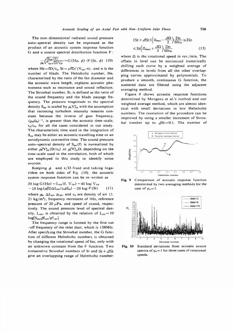
Figure 9 shows acoustic response functions
determined by Mongeau et a .'s method and
our
weighted average method, which are almost iden
tical with small deviations in low Helmholtz
numbers.
The
resolution of the procedure can be
improved by using a smaller increment of Strou
hal number up to LISt=O.1. The number of
The non-dimensional radiated sound pressure
auto-spectral density can be expressed as the
product
of
an acoustic system response function
G and a source spectral distr ibution function F :
~
G(He,
if;
·F St.
if;
(10)
Po
v
2
t1p
JI),lC;
where
He=fD/c
o
,
St=JrfD/ Vup·n , and n is the
number of blade. The Helmholtz number, He,
characterized by the ratio of the fan diameter and
the acoustic wave length, explains acoustic phe
nomena such as resonance and sound reflection.
The Strouhal number, St, is defined as the ratio
of
the sound frequency and the blade passage fre
quency. The pressure magnitude in the spectral
density Spp is scaled by
V[IP
with the assumption
that incoming turbulent intensity remains con
stant because the inverse
of
gust frequency,
(P8
D
O -1, is greater than the acoustic time-scale,
ro/c
o
for all the cases considered in our study.
The characteristic time used in the integration
of
Spp may be either an acoustic travelling time or an
aerodynamic convective time. The sound pressure
auto-spectral density of
Spp I
is normalized by
either dVtIP(D/co) or
d V ~ l p
depending on the
time-scale used in the correlation, both of which
are employed in this study to identify noise
sources.
Keeping
if; and x/D
fixed and taking loga
rithm on both sides of Eq. (10), the acoustic
system response function can be re-writ ten as
20 log G He =Lpp f, V
up
)
-40
log V
up
-10
log dDMreti o P ~ e r - 20 log F (St)
I I
5 I
SlrQuII<Ilnumber
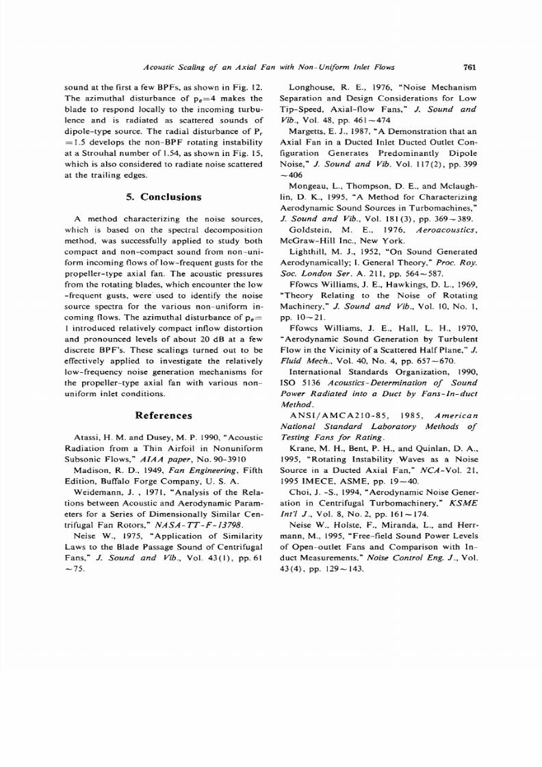
Standard deviations from acoustic source
spectra of P8= 1for threecasesof rotational
speeds
II
17
II
. ::
12
11
1 0
01
07
01
os
O•
.,
0 2
01
00
.(I I t _ ~ _ ~ _ ~ ~ _ ~ ~ _
Fig. 10
where Po
~ f r e f
Prer and o are density of air I .
21 kg/rn ), frequency increment of 1Hz, reference
pressure of 20 t tPa, and speed of sound, respec
tively. The sound pressure level of spectral den
sity, L
pp,
is obtained by the relation of Lpp= 10
log[SppLIf
rer/
p2rer]
The frequency range is limited by the first cut
-off
frequency of the inlet duct, which is 1380Hz.
After specifying the Strouhal number, the G func
tion of different Helmholtz numbers is obtained
by changing the rotational speed of fan, only with
an unknown constant from the F function.
Two
consecutive Strouhal numbers of St and St
+
LISt
give an overlapping range
of
Helmholtz number:

8/11/2019 Acoustic Scaling of Axial Fan
http://slidepdf.com/reader/full/acoustic-scaling-of-axial-fan 9/10
760
Seungbae Lee n Gwi Chul Yang
5 6
SlrouhaII ltJITiler
Fig. 13 The source spectral distribution function
determined by the in-duct method for the
case of
Pe=2
-95
-90
0, t 2 0.3 0.4
0 8
0.7 8 0,9
Helmholtz
num r
Acoustic response functions by two differ
ent scaling parametersfor the caseof Pe=
eo
3 .
A
- 9 5 O r p m
/
-85
- 1 0 5 0 r p m
30
-70
115Orpm
I
m
125Orpm
(;'
,.
/B
;r
-75
135Orpm
'
2
0
»>
Fig. 11
The source spectral distribution function
determined by the in-duct method for the
case of Pe= I.
-50
-55
- 9 5 O r p m
eo
- 1 0 5 ) p m
s
- 1 1 5 C ) p m
i r
-70
- 1 2 5 C ) p m
I
- 1 3 5 O r p m
- Ill
-95
-100
s
6
StrouhaI n mer
Fig. 12
10
s
- 9 5 O r p m
·70
- 1 0 5 ) p m
- 1 1 5 C ) p m
-75
- 1 2 5 ) p m
- 1 3 5 O r p m
8
i i
- Ill
-95
-100
5 8
StrouhaI
ruTiler
Fig. 4 The source spectral distribution function
determined by the in-duct method for the
case of
p =4
rotational speeds also affect the standard deriva
tions at each Strouhal number, as shown in Fig.
10, where the mean square e rrors are reproduce d
as an indication of accuracy for the spectral
decomposition. Two different scaling parameters
for low-frequent gust problems produce quite
different acousti c behaviors in the G function as
shown in Fig. II. The case with a convective
c or rel ati on time-s cale is considered to include
i mpedance effects in the G function, whereas the
effect
of
impedance are put together with the
scaling parameter for
our
case with an acoustic
correlation time-scale.
The source spectral distribution function F can
be obtained by substracting G He) from their
spectrum of L
pp
•
The
results are given in Fig. 12
th ro ugh Fig. 15 for four different n on -u ni fo rm
inlet conditions.
From
the fact that all five spectra
c ol la pse into a single curve w it hi n a few dB, it can
be sta te d t ha t the sca li ng para me ters for the spec
tral energy density are effective at low S trouha l
- 9 5 O r p m ,
- 1 ) 5 ) p m
115Orpm
125Orpm
-13 1 pm
5 6
StrouhaII lI ITtler
Fig.
The source spectral distribution function
determined by the in-duct method for the
case of Pr= 5
numbers for the low-frequency inflow distortions.
The
source spectral distribution functions from
various non-uni form it ie s show more promi ne nt
peaks at each Str ou hal n umb er th an the n or mal
ized cross-spectra given in Fig.
8.
The azimuthal
disturbance of P8= I i nt roduce s relatively more
co mpa ct inflow dis to rtio n, where the blades go
through the fluctuations of total loading as a
whole, and generates an increased level of discrete
8/11/2019 Acoustic Scaling of Axial Fan
http://slidepdf.com/reader/full/acoustic-scaling-of-axial-fan 10/10
Acoustic Scaling of an Axial Fan with Non- niform inlet
lows
7
sound at the first a few BPFs, as shown in Fig. 12.
The
azimuthal disturbance of Pe=4 makes the
blade to respond locally to the incoming turbu
lence and is radiated as scattered sounds of
dipole-type source. The radial disturbance of P,
=
1.5 develops the non-BPF rotating instability
at a Strouhal number of 1.54,as shown in Fig. 15,
which is also considered to radiate noise scattered
at the trailing edges.
Conclusions
A method characterizing the noise sources,
which is based on the spectral decomposition
method, was successfully applied to study both
compact and non-compact sound from non-uni
form incoming flows of low-frequent gusts for the
propeller-type axial fan. The acoustic pressures
from the rotating blades, which encounter the low
-frequent gusts, were used to identify the noise
source spectra for the various non-uni fo rm in
coming flows. The azimuthal disturbance of Pe=
1 introduced relatively compact inflow distortion
and pronounced levels of about 20 dB at a few
discrete BPF s. These scalings turned out to be
effectively applied to investigate the relatively
low-frequency noise generation mechanisms for
the propel le r-type axial fan with various non
uniform inlet conditions.
References
Atassi, H. M. and Dusey, M. P. 1990, Acoustic
Radia tion from a
Thin
Airfoil in Nonuniform
Subsonic Flows,
AIAA
paper
No. 90-3910
Madison, R. D., 1949, Fan Engineering Fifth
Edition, Buffalo Forge Company,
U
S. A.
Weidemann, J. , 1971, Analysis of the Rela
tions between Acoustic and Aerodynamic Param
eters for a Series
of
Dimensionally Similar Cen
trifugal Fan Rotors, NASA TT F 13798
Neise W., 1975, Appl icat ion
of
Similarity
Laws to the Blade Passage Sound of Centrifugal
Fans,
J Sound
and Vib. Vol. 43 (1), pp.61
-75.
Longhouse, R. E., 1976, Noise Mechanism
Separation and Design Considerations for Low
Tip-Speed, Axial-f low Fans,
J
Sound and
Vib. Vol. 48, pp.
461-474
Margetts, E. J., 1987, A Demonstration that an
Axial
Fan
in a Ducted Inlet Ducted Outlet Con
figuration Generates Predominant ly Dipole
Noise,
J Sound
and Vib Vol. 117(2), pp. 399
-406
Mongeau, L., Thompson, D. E., and Mclaugh
lin, D. K., 1995, A Method for Characterizing
Aerodynamic Sound Sources in Turbornachines,
J Sound and Vib. Vol. 181(3), pp.
369-389.
Goldstein,
M. E., 1976,
Aeroacoustics
,
McGraw-Hill
Inc., New York.
Lighthill, M. J., 1952, On Sound Generated
Aerodynamically; I General Theory, Proc. Roy.
Soc. London Ser.
A. 211, pp. 564-587.
Ffowcs Williams, J. E., Hawkings, D.
L.,
1969,
Theory Relating to the Noise of Rotating
Machinery,
J Sound and
Vib. Vol. 10, No. I
pp. 10-21.
Ffowcs Williams, J. E., Hall,
L.
H., 1970,
Aerodynamic Sound Generation by Turbulent
Flow in the Vicinity
of
a Scattered Half Plane,
J
Fluid Mech. Vol. 40, No.4, pp.
657-670.
International Standards Organization, 1990,
ISO 5136 Acoustics-Determination of Sound
Power Radiated into a Duct by Fans in duct
Method.
ANSI AMCA210-85,
1985,
American
National St and ar d Laboratory Methods of
Testing Fans for Rating.
Krane, M. H., Bent, P.
H
and Quinlan, D. A.,
1995, Rotating Instability Waves as a Noise
Source in a Ducted Axial
Fan,
NCA Vol 21
1995 IMECE, ASME, pp. 19-40.
Choi,
J.
-S., 1994, Aerodynamic Noise Gener
ation in Centrifugal Turbornachinery, KSME
Int l
J
Vol. 8,
No.2,
pp.
161-174.
Neise W., Holste, F., Miranda, L., and Herr
mann, M., 1995, Free-field Sound Power Levels
of Open-outlet Fans and Compar ison with In
duct Measurements, Noise Control Eng.
J
Vol.
43(4), pp.
129-143.


![[PPT]Scaling properties of deep neural network acoustic …web.stanford.edu/class/cs224s/lectures/224s.17.lec7.pptx · Web viewCS 224S / LINGUIST 285Spoken Language Processing Andrew](https://static.fdocuments.in/doc/165x107/5aee5d097f8b9ae53191a8bd/pptscaling-properties-of-deep-neural-network-acoustic-web-viewcs-224s-linguist.jpg)