Acoustic Guitar with Resonance Speaker Technology
65
Resonance Speaker Technology 1 Sam Cox 2021 Acoustic Guitar with Resonance Speaker Technology SAMUAL COX N00170308 SUPERVISOR: PAUL COMISKEY SECOND READER: SHANE BYRNE YEAR 4 2020-2021 DL835 BSC(HONS) IN CREATIVE MEDIA TECHNOLOGIES
Transcript of Acoustic Guitar with Resonance Speaker Technology

Resonance Speaker Technology 1 Sam Cox
2021
Acoustic Guitar with Resonance Speaker Technology
SAMUAL COX
N00170308
SUPERVISOR: PAUL COMISKEY
SECOND READER: SHANE BYRNE
YEAR 4 2020-2021
DL835 BSC(HONS) IN CREATIVE MEDIA TECHNOLOGIES

Resonance Speaker Technology 2 Sam Cox
Acknowledgements
I would like to thank my project supervisor Paul Comiskey for his support throughout the course of this project as it would not have been possible without him. His creative feedback and encouragement helped this project immensely.
Furthermore, I would like to thank my second reader Shane Byrne whose creative questions helped form the final product by adding a unique perspective on the project and how he would personally use it.
An additional thank you to Conor Brenan who initially acted as second reader for this project as his interest in the project helped to push the project forward.
Lastly, this project could not have been completed without using skills and experience formed over the previous four years thanks to all the resources the institute had to offer, including exceptional facilities and great teaching staff.

Resonance Speaker Technology 3 Sam Cox
Abstract
This study examines the use of resonance speaker technology in an acoustic guitar body. A resonance speaker can be used to vibrate the body of the guitar much in the same way playing the strings vibrate the guitar and can therefore be used to add audio effects such as delay and even play back recorded guitar audio with the use of a loop pedal allowing for expansive, multi-layered melodies to be projected from one guitar. This document outlines how current products use this technology as well as documenting the creation of a new and innovative way to approach this technology and add extensive functionality to the humble acoustic guitar.

Resonance Speaker Technology 4 Sam Cox
Table of Contents
1 Introduction .................................................................................................................................... 6
2 Research Chapter ............................................................................................................................ 7
2.1 Introduction ............................................................................................................................ 7
2.2.1 Resonance Speaker ......................................................................................................... 7
2.2.2 Guitar Effects................................................................................................................... 8
2.2.3 Guitar Peripherals and Innovation in the Modern Day (Robot Tuners) ......................... 9
2.2.4 Acoustic Guitar Pickup .................................................................................................. 10
2.3 Applications ........................................................................................................................... 11
2.4 Requirements ........................................................................................................................ 12
2.4.1 Similar products ............................................................................................................ 12
2.4.2 Circuit building .............................................................................................................. 14
2.4.3 Fabrication and installation .......................................................................................... 14
2.4.4 Understanding of the end user ..................................................................................... 14
2.4.5 Desired Outcome .......................................................................................................... 14
2.5 Conclusion ............................................................................................................................. 15
3 Design ............................................................................................................................................ 16
3.1 Introduction .......................................................................................................................... 16
3.2 Overview of the Design ......................................................................................................... 17
3.2.1 Circuit Overview ............................................................................................................ 17
3.2.2 Onboard Circuit Diagram .............................................................................................. 17
3.2.3 Effects Unit Diagram ..................................................................................................... 21
3.2.4 Amplifier Circuit Circuit Diagram .................................................................................. 23
3.2.5 Enclosure and 3D Fabrication Design............................................................................ 25
3.3 Conclusion ............................................................................................................................. 31
4 Implementation ............................................................................................................................ 32
4.1 Introduction .......................................................................................................................... 32
4.2 Prototype 1 ................................................................................................................................. 32
4.2.1 Process .......................................................................................................................... 32
4.2.2 Features ........................................................................................................................ 35
4.2.3 Issues .................................................................................................................................... 35
4.2.4 Resolution of Issues ............................................................................................................. 36
4.3 Prototype 2 ................................................................................................................................. 36
4.3.1 Process .......................................................................................................................... 36
4.3.2 Features ........................................................................................................................ 38

Resonance Speaker Technology 5 Sam Cox
4.3.3 Issues ............................................................................................................................. 38
4.3.4 Resolution of Issues ...................................................................................................... 38
4.4 Prototype 3 .......................................................................................................................... 38
4.4.1 Process .......................................................................................................................... 38
4.4.2 Features ........................................................................................................................ 40
4.4.3 Issues ............................................................................................................................. 40
4.4.4 Resolution of Issues ...................................................................................................... 40
5 Testing & Results ........................................................................................................................... 41
5.1 Introduction .......................................................................................................................... 41
5.2 Tests & Results ...................................................................................................................... 41
5.2.1 Distortion Circuit ........................................................................................................... 41
5.2.2 Pre-Amplifier Circuit ...................................................................................................... 43
5.2.3 Amplifier Circuit Prototypes .......................................................................................... 46
5.2.4 Final Amplifier Circuit .................................................................................................... 47
5.2.5 Delay Circuit .................................................................................................................. 48
5.3 Interpretation of Results ....................................................................................................... 49
5.4 Conclusions ........................................................................................................................... 49
6 Conclusion ..................................................................................................................................... 50
Appendix ............................................................................................................................................... 51
References ............................................................................................................................................ 65

Resonance Speaker Technology 6 Sam Cox
1 Introduction
Playing a musical instrument is one of the most common pastimes across the world with the guitar one of the most popular instruments to play. A recent study conducted in the United Kingdom found 76% of children in Northern Ireland, for example, play an instrument (Royal Academy of Music, 2014). The acoustic guitar has remained relatively unchanged in functionality for decades and following the introduction of the solid body electric guitar in the mid-20th century, it too has remained faithful to its early prototypes. While there are of course exceptions, acoustic guitars are often fitted with digital tuners and pickups for example, and electric guitars can be found with a wide variety of electrical components installed. However, new innovations in the field are often rejected due to traditionalist values and can come with serious ramifications. In a now infamous report by the Washington Post, entitled “The Death of The Electric Guitar”, Geoff Edgers stated in relation to Gibson’s then latest innovation, robotic tuners, that “Gibson spent more than a decade and millions of dollars developing” and when they became a standard feature on their guitars “sales dropped so dramatically, as players and collectors questioned the added cost and value, that Gibson told dealers to slash prices. “(Washington Post, 2017). This project aims to incorporate resonance speaker technology into an acoustic guitar allowing the playing to use standard effects pedals without the need for a traditional amplifier. This allows a player to create a huge array of unique sounds without the need for mains power. The project involves the fabrication of a delay and amplifier circuit allowing the user to play acoustic guitar with reverb and delay without any other equipment and will run on a 9V battery, requiring only one stereo cable to interface the guitar with the circuitry.

Resonance Speaker Technology 7 Sam Cox
2 Research Chapter 2.1 Introduction
This chapter aims to investigate the technologies needed to make this project feasible. In addition, it is also an aim to research guitar accessories that have been introduced to both positive and negative fanfare and theorise why this may be the case. A supplementary aim is also to investigate how this project could become a mainstream product used by acoustic guitar players to enhance their sound and playing experience.
2.2 Area of Research
2.2.1 Resonance Speaker
The idea of a resonance or vibration speaker is quite simple. By vibrating a material, the material acts as the diaphragm of the speaker, altering the sound to varying degrees due to its own inherent resonant characteristics. “The solid surface will vibrate with the speaker, displacing air molecules around it. Just as with any other sound, your ear detects the movements of the colliding air molecules. Some materials reverberate better than others -- not all solids are created equal. In general, glass and wood tend to work best with vibration speakers.”(HowStuffWorks, 2012). The idea can be used in a number of situations and in certain conditions can prove beneficial due to the piece of hardware being significantly smaller than the speaker it intends to replace. This is due to the fact there is no large additional diaphragm membrane needed to drive the sound. These properties can of course have extreme effects on the sound. If the speaker was placed on a stainless-steel countertop for example, it would incorporate resonance characteristics of that material and may act similarly to a plate reverb effect, whether that was the desired effect or not. Resonance speakers can be seen in numerous devices today. One good example is the mobile phone. As phones move towards higher screen-to-body ratios, (the surface area covered by screen in relation to the surface area covered by housing and components on the front of a phone), there is less room for speakers and more importantly less room for speaker grills on the front of phones for calls. This has led companies such as LG to move towards resonance technologies with the glass screen acting as a pseudo speaker membrane. It is important to note that LG’s implementation is unique in that it uses the empty space within a phone as a resonance chamber firstly before vibrating the phone. The need for this innovation was outlined as follows: “As smartphone displays get bigger, brighter and more colourful, their speakers should get better too, right? Unfortunately, as the casings get thinner and the batteries larger, space for high quality speakers has seemingly been sacrificed.”(LG Magazine, 2018)
Figure 1: Promotional Material for LG G7 ThinQ (LG Magazine, 2018)

Resonance Speaker Technology 8 Sam Cox
2.2.2 Guitar Effects
Guitar effects units are used by guitarists and sound engineers to alter the output of a guitar in all manners of ways. In the early days of guitar amplification and electrification, guitarists, and engineers such as Les Paul were attempting to create an authentic, clean reproduction of their guitars sound. However, over time the natural distortion of valve amplifiers and other effects began to become more sought after than avoided. ” From the earliest days of recording, musicians and engineers strove to eliminate distortion, which was viewed as “bad sound.” But some innovative musicians railed against that smooth sound and crafted methods to incorporate those “bad sounds” into their music, hearing them as bold new musical colours and textures that helped fuel the rock ‘n roll revolution.” (Disc Makers, 2016). While effects units are more traditionally paired with electric guitars, acoustic guitar players often use effects pedals to add to their sound. Effects pedals are used more commonly with an electric guitar for various reasons:
• Acoustic guitars project sound acoustically far more efficiently than electric guitars and therefore the acoustic sound can be heard in tandem with the processed sound to varying degrees depending on the level of amplification. This makes distortion pedals less pronounced when used in small venues, for example, as the clean acoustic sound can also be heard.
• Another issue with effects pedals and acoustic guitars is the acoustic guitar’s increased tendency to induce feedback, amplified greatly when using distortion or boost pedals. Feedback refers to the positive loop gain that can occur when a sound loop exists between the input and output audio.
• Acoustic guitars are by nature acoustic. Many players do not incorporate an amplifier into their playing whether due to convenience, keeping the volume to a minimum or a lack of access to mains power. Without the use of an amp, it is not usually possible to incorporate effects into your sound.
Some common effects used for acoustic guitar are: Reverb, delay, chorus, tremolo, phaser, flanger, EQ and loop pedals. Many of these effects work well with acoustic guitars because they are designed to be used with a partially dry signal, even when an electric guitar is used. It is intended to hear the dry (unprocessed) audio as well as the wet (processed audio) in many cases. With a delay pedal, for example, you typically hear the dry signal and then a fraction of a second later you hear that same audio repeated while slowly decaying, with reverb acting similarly. Chorus and other modulation effects (flanger, phaser and tremolo) are often heard with a relatively high amount of dry signal, making them more suited to acoustic guitar playing. Many of these effects, such as reverb, delay, and chorus, aim to mimic real-world acoustic phenomena making them a better fit for acoustic instruments. Using a software environment called LTspice, simulations were carried out on the effect of a distortion unit on acoustic guitar audio recorded with the guitar used for the project and will

Resonance Speaker Technology 9 Sam Cox
be examined in detail in the Testing and Results chapter. LTspice is a “high performance SPICE simulation software, schematic capture and waveform viewer with enhancements and models for easing the simulation of analog circuits.” (LTspice, 2020). LTspice allows for schematics of circuits to be created and simulated, giving the user the ability to run a wide variety of tests involving audio, power consumption and more. 2.2.3 Guitar Peripherals and Innovation in the Modern Day (Robot Tuners)
Guitar modifications have always been received with scepticism in the music world. Guitarists are generally traditionalists, with analogue effects and vintage guitars held in high regard. At the time of their introduction, these advancements were often received poorly as mentioned earlier in relation to distortion. Early guitar pickups and amplifiers were designed for guitar players, largely jazz players at the time, but did not give the authentic clean sound the musicians were looking for. However, in the present day these technologies, such as valve amps, P90 and PAF (Patent Applied For, an early model of humbucking pickup used in Gibson guitars in the 1950’s and early 1960’s) pickups and early distortion pedals, are revered for their unique characteristics, ever if they are simply a by-product of the limitations of that time. Many modern-day modifications are met with similar scepticism, with Gibson facing huge backlash and financial losses in the mid 2010’s due to their alterations to classic guitar designs, most notably the introduction of “Robot Tuners”, automatic guitar tuners made to make the tuning process, whether changing tuning altogether or getting the strings back into tune, completely automated. These guitars sold poorly and became a contentious issue in the guitar and music retail world. “It made its Gibson debut in 2007, but only in 2015 did it become a standard component in the company’s guitars. It didn’t stick. Players found G FORCE unnecessary, over-complicated and a little wonky; many even paid to remove the system from their six-strings. And so, the system was gradually dropped over the years, only appearing on a few of Gibson’s 2018 models.” (Guitar, 2018)
Figure 2: The G Force Tuning System (Guitar,2018)
Resonance Speaker Technology 10 Sam Cox
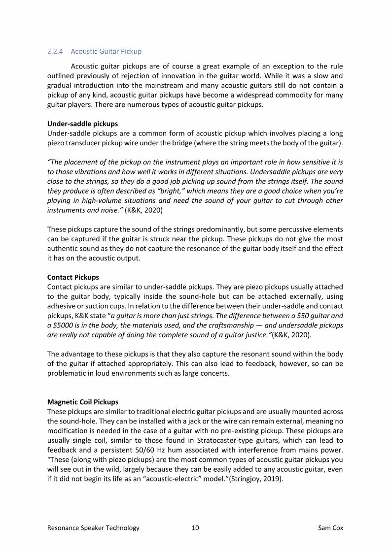
2.2.4 Acoustic Guitar Pickup
Acoustic guitar pickups are of course a great example of an exception to the rule outlined previously of rejection of innovation in the guitar world. While it was a slow and gradual introduction into the mainstream and many acoustic guitars still do not contain a pickup of any kind, acoustic guitar pickups have become a widespread commodity for many guitar players. There are numerous types of acoustic guitar pickups. Under-saddle pickups Under-saddle pickups are a common form of acoustic pickup which involves placing a long piezo transducer pickup wire under the bridge (where the string meets the body of the guitar). “The placement of the pickup on the instrument plays an important role in how sensitive it is to those vibrations and how well it works in different situations. Undersaddle pickups are very close to the strings, so they do a good job picking up sound from the strings itself. The sound they produce is often described as “bright,” which means they are a good choice when you’re playing in high-volume situations and need the sound of your guitar to cut through other instruments and noise.” (K&K, 2020) These pickups capture the sound of the strings predominantly, but some percussive elements can be captured if the guitar is struck near the pickup. These pickups do not give the most authentic sound as they do not capture the resonance of the guitar body itself and the effect it has on the acoustic output. Contact Pickups Contact pickups are similar to under-saddle pickups. They are piezo pickups usually attached to the guitar body, typically inside the sound-hole but can be attached externally, using adhesive or suction cups. In relation to the difference between their under-saddle and contact pickups, K&K state “a guitar is more than just strings. The difference between a $50 guitar and a $5000 is in the body, the materials used, and the craftsmanship — and undersaddle pickups are really not capable of doing the complete sound of a guitar justice.”(K&K, 2020). The advantage to these pickups is that they also capture the resonant sound within the body of the guitar if attached appropriately. This can also lead to feedback, however, so can be problematic in loud environments such as large concerts. Magnetic Coil Pickups These pickups are similar to traditional electric guitar pickups and are usually mounted across the sound-hole. They can be installed with a jack or the wire can remain external, meaning no modification is needed in the case of a guitar with no pre-existing pickup. These pickups are usually single coil, similar to those found in Stratocaster-type guitars, which can lead to feedback and a persistent 50/60 Hz hum associated with interference from mains power. “These (along with piezo pickups) are the most common types of acoustic guitar pickups you will see out in the wild, largely because they can be easily added to any acoustic guitar, even if it did not begin its life as an “acoustic-electric” model.”(Stringjoy, 2019).
Resonance Speaker Technology 11 Sam Cox
Microphone-Paired Pickups These pickups usually incorporate one of the previously mentioned pickup types with a small microphone and preamp embedded in the guitar itself and allows for the two pickup types to be blended to create the desired sound and combat issues such as feedback. Microphone-paired pickups give a “diverse range of tones available to the player, depending on the application” and the “microphone can be turned down if feedback is an issue.”(Stringjoy, 2019).
2.3 Applications
Guitar effects and amplification in general are used in a wide range of cases. While they are often used when practicing the instrument, they can be key in live environments such as concerts. This may be to recreate a sound heard on a record or just to create a more interesting sound for the audience that is better fitted to the sound being performed. Reverb, delay and chorus are of big importance to this project in particular, as they are some of the most commonly used effects in acoustic guitar signal chains. This project aims to create a product that could be used not only for practicing but also for small concerts and music sessions where traditional amplification may not be welcome or needed. The project aims to create a platform for acoustic guitar players to add depth to their sound without the need for a heavy amplifier. The project strives to allow players to also incorporate loop pedals into the signal chain, allowing a guitarist to accompany themselves without an amplifier. This is again good for small venues but also for practicing where loud volume may be an issue, where it may be too tedious to set up an amplifier, or where you may be practicing away from mains power or away from your amp, such as outdoors or simply in a different room in your house. By allowing for the use of a loop pedal, the system does allow for the guitar to be minimally louder than without it, but its main focus is on incorporating effects processing and looping with the potential for addition volume as an added bonus for those performing in small venues where it may be appreciated.
Resonance Speaker Technology 12 Sam Cox
2.4 Requirements 2.4.1 Similar products
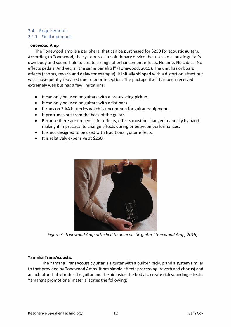
Tonewood Amp The Tonewood amp is a peripheral that can be purchased for $250 for acoustic guitars.
According to Tonewood, the system is a “revolutionary device that uses an acoustic guitar's own body and sound-hole to create a range of enhancement effects. No amp. No cables. No effects pedals. And yet, all the same benefits!” (Tonewood, 2015). The unit has onboard effects (chorus, reverb and delay for example). It initially shipped with a distortion effect but was subsequently replaced due to poor reception. The package itself has been received extremely well but has a few limitations:
• It can only be used on guitars with a pre-existing pickup.
• It can only be used on guitars with a flat back.
• It runs on 3 AA batteries which is uncommon for guitar equipment.
• It protrudes out from the back of the guitar.
• Because there are no pedals for effects, effects must be changed manually by hand making it impractical to change effects during or between performances.
• It is not designed to be used with traditional guitar effects.
• It is relatively expensive at $250.
Figure 3. Tonewood Amp attached to an acoustic guitar (Tonewood Amp, 2015)
Yamaha TransAcoustic
The Yamaha TransAcoustic guitar is a guitar with a built-in pickup and a system similar to that provided by Tonewood Amps. It has simple effects processing (reverb and chorus) and an actuator that vibrates the guitar and the air inside the body to create rich sounding effects. Yamaha’s promotional material states the following:

Resonance Speaker Technology 13 Sam Cox
“There’s nothing so inspiring as playing guitar in a great sounding room – it makes you play better, longer and with more creativity. The Yamaha TransAcoustic Guitar recreates that incredible experience without needing any external amplification or effects, just the guitar itself. It’s the most inspiring, engaging acoustic guitar you’ve ever played.”(Yamaha, 20) The advantage of this system over the Tonewood Amp is that the system is completely integrated into the guitar, with just three control knobs protruding from the guitar. The system and the built-in pickup all run off the same battery compartment using standard 9V batteries and involves no cables. Tonewood also claim to need no cables but there is in fact one cable needed to connect their system to the output of the guitar. The TransAcoustic does have a few limitations however:
• Limited to built-in effects (reverb and chorus)
• Cannot be installed in other guitars: Limited product range meaning there may not be a guitar that suits all players (No smaller scale length guitars for example or other acoustic instruments such as acoustic bass or bouzouki)
• Relatively expensive investment if the player already owns an acoustic guitar and is buying this product just for its additional feature (starting at $1200)
• Effects can’t be controlled with a foot switch, but the limited number of effects can be quickly adjusted with the control knobs on the side of the guitar like traditional acoustic pre-amp controls.
Figure 4. User changing effects controls on a TransAcoustic (Yamaha, 20
Resonance Speaker Technology 14 Sam Cox
2.4.2 Circuit building
This project may appear simple at a glance, but in order for the processed sound to be audible, a degree of amplification is needed. While not much amplification is needed for a slight reverb or delay effect to be audible, if the user wants to use a loop pedal, for example, the output volume must be similar to that of in the guitars acoustic volume. For this to be successful, an amplifier circuit is needed but must be small in size and power consumption. If the amplifier circuit were too large it would detract from the ease of use and portability of the product and it must also be able to run on batteries, whether that be a standard 9V battery used for most guitar related products or a more substantial portable battery like those used for multi-effects pedals. 2.4.3 Fabrication and installation
The project involves a level of fabrication that may prove difficult. The amplifier circuit outlined above, would need an enclosure to be rugged and safe for transport. However, with the ongoing restrictions a 3D printed enclosure, or laser cut wooden enclosure as initially hoped, may not be possible, at least at this time. If this remains the case throughout the year, a suitable replacement, whether sourced or fabricated, will have to be used instead. The speaker circuitry, however, can be installed with limited tools and supplies, needing only 3M adhesive and a soldering iron with good quality solder. 2.4.4 Understanding of the end user
This project requires a deep understanding of a wide variety of types of guitar players. This ranges from beginners to professionals, acoustic guitar players to electric guitar players and any combination of these two parameters. This understanding is achieved through not only playing guitar for numerous years and examining the market of already available products and their reception but also through the testing, both formally and informally, on fellow guitar players, online or in person, depending on restrictions. 2.4.5 Desired Outcome
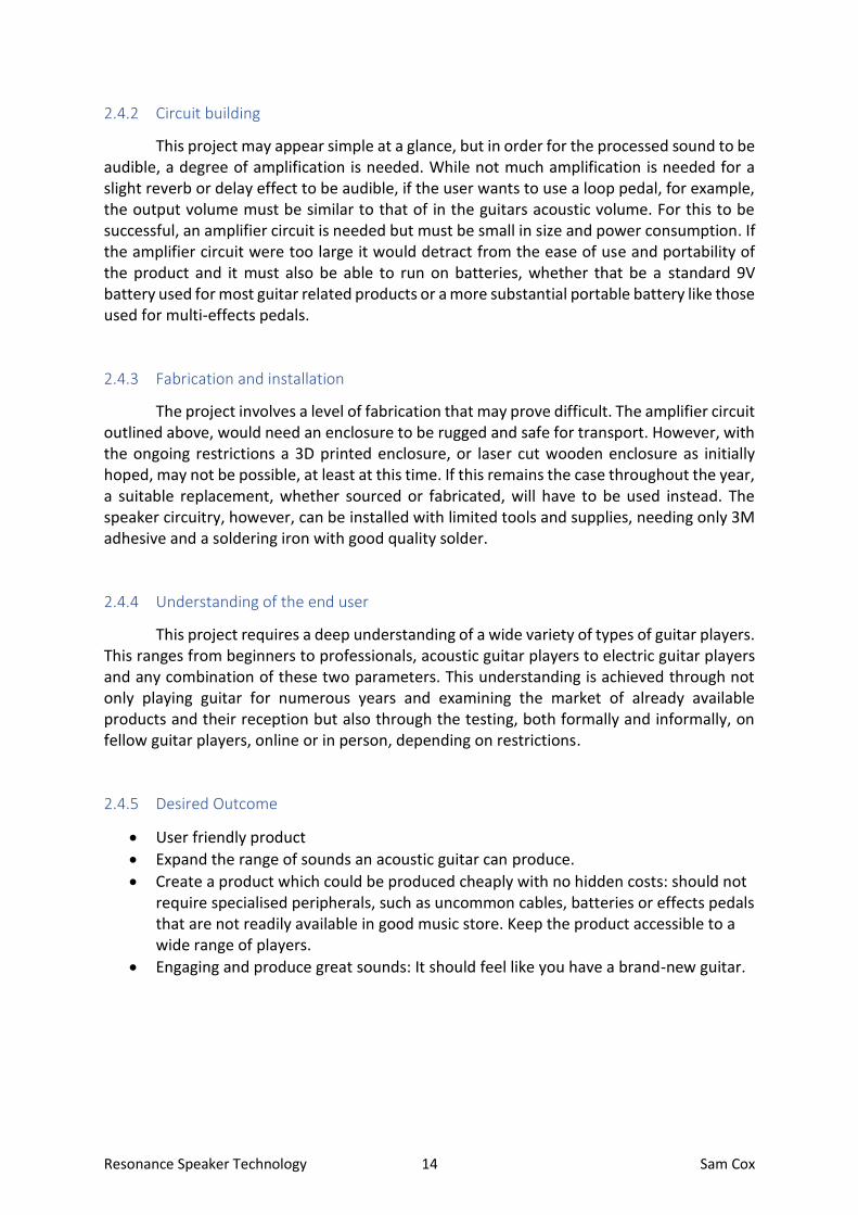
• User friendly product
• Expand the range of sounds an acoustic guitar can produce.
• Create a product which could be produced cheaply with no hidden costs: should not require specialised peripherals, such as uncommon cables, batteries or effects pedals that are not readily available in good music store. Keep the product accessible to a wide range of players.
• Engaging and produce great sounds: It should feel like you have a brand-new guitar.
Resonance Speaker Technology 15 Sam Cox
2.5 Conclusion In conclusion, this chapter has investigated and outline what is available in terms of
technologies and products, how they work and their unique advantages and disadvantages. It has created a foundation to work from, in the design and development of this project and has illustrated potential issues and what is needed for the project to be deemed a success. As the project continues to evolve, further research and testing will continue where necessary and will be outlined in later chapters. This project aims to add crucial features to acoustic guitars not currently available and will be unique to those already on the market. While it aims to correct some of the disadvantages of available products, it may also create its own limitations and will be tested thoroughly with this research used for comparison.

Resonance Speaker Technology 16 Sam Cox
3 Design 3.1 Introduction
This core concept of this project is incorporating resonance speaker technology into an acoustic guitar body. This is achieved by outputting the guitar’s signal, using an acoustic guitar pickup, and amplifying the signal using external circuitry before the signal is directed back into the guitar. This resonates the body and produces any effect the user chooses to add or simply amplifies the sound. One key focus of this project is to create a project that is simple to operate without the need for specialized equipment such as cables and batteries that are not readily available in music stores. User experience is fundamental to the success of this project and the project aims to add as much functionality as possible while keeping the product relatively simple to operate and reducing the number of potential issues by only including exactly what is needed for the product to function optimally. Another priority in relation to the product is for it to be removable. While the product attaches to a guitar securely with 3M tape, the product is removable and requires no additional holes or modifications to be installed. This is crucial as it prevents guitars from losing value should the user want to sell on their guitar as well as leaving the guitar intact from a preservation perspective.

Resonance Speaker Technology 17 Sam Cox
3.2 Overview of the Design 3.2.1 Circuit Overview
The circuit itself can be split into a few main modules/components; the pickup, preamp, effects unit/s, amplifier, and speaker. The block diagram below (Figure 5) shows a simplified circuit diagram containing these elements. The vibration caused by the guitar’s resonance causes the transducer pickup to vibrate. This mechanical energy is converted into a weak electrical signal by the piezo crystals found in the pickup. That weak signal is amplified to instrument level by the onboard Fishmen pickup system. That signal is then processed by whatever effects units the user connects and then amplified by the amplifier circuit. That signal then causes the resonance speaker inside the guitar to vibrate creating an audible response.
Figure 5: Block diagram showing general circuit design.
3.2.2 Onboard Circuit Diagram
Several important modifications were needed inside the guitar for this project to be possible. The guitar used, a Harley Benton GS-Travel, did not originally come with a pickup system (some models are now equipped with a simple pickup system), so a pickup had to be added. The Fishman Presys was chosen for this project. It consists of a piezo transducer pickup that sits under the bridge of the guitar which requires a small hole to be drilled for cable routing into the body. This pickup is then connected to the preamp system mounted in the side of the guitar which conveniently houses the 9V battery as well (some units require a second hole in the guitar to be cut for the battery compartment). This system does not have a power switch but instead opts to use a stereo jack as a switch. When the guitar player inserts a standard mono guitar cable into the jack it bridges the ring and sleeve connections and turns on the preamp circuit (see Figure 6). This is an ingenious and user-friendly solution but makes this project far more complicated as it removes the use of the extra connection found in the stereo jack that would be needed to send a return signal to the guitar and makes the use of a stereo cable impossible (see Figure 7).

Resonance Speaker Technology 18 Sam Cox
Figure 6: Diagram shows both GND wires connect when a mono cable is used.
Figure 7: Diagram shows GND wires are not connect when a stereo cable is used. The preamp
would not operate.
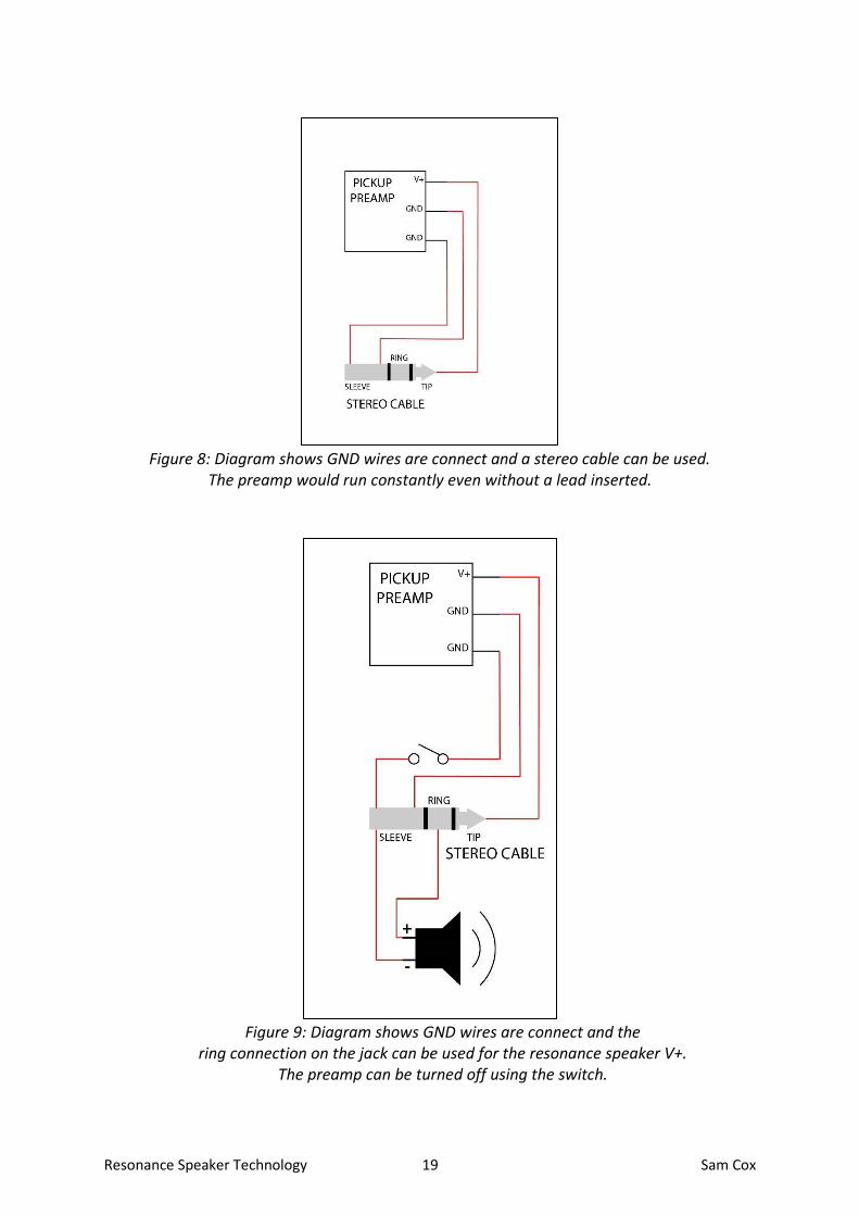
The solution to this problem was to connect both V- connections from the preamp to the common ground of the jack. This would cause the battery to drain quickly as the preamp would be running constantly (see Figure 8). To solve this issue, one of the V- wires had a switch added to it simulate what would usually happen when the player inserts a mono jack (see Figure 9).
Resonance Speaker Technology 19 Sam Cox
Figure 8: Diagram shows GND wires are connect and a stereo cable can be used. The preamp would run constantly even without a lead inserted.
Figure 9: Diagram shows GND wires are connect and the ring connection on the jack can be used for the resonance speaker V+.
The preamp can be turned off using the switch.

Resonance Speaker Technology 20 Sam Cox
The final circuit for the onboard electronics can be seen below in Figure 10. Note the stereo jack is now acting as both an input and output jack with one the tip of the cable, traditionally used as the left channel in stereo applications, used as the output from the pre-amp. That signal is processed by outboard electronics (effects and amplification circuits) and is then returned via the ring connection (traditionally the right channel), sending the processed signal to the resonance speaker.
Figure 10: Circuit diagram of onboard electronics.

Resonance Speaker Technology 21 Sam Cox
3.2.3 Effects Unit Diagram
To demonstrate the possibilities this project opens up in terms of sound, a delay circuit was added as a basic effect that can be used at the end of an effects chain of guitar pedals or used independently. Delay was chosen as while it can produce reverb-like delay using smaller time domains, it can also produce expansive delays which create a sound not usually possible acoustically (except for in large rooms which can produce echo) while not sounding synthesized due to the simplicity of the effect. The effect repeats the audio input multiple times with each repetitions volume lower than the last, known as decay. The time between the repetitions, the mix between the unaltered signal and the processed signal and the number of repetitions is all adjustable using potentiometers. The delay circuit itself is based on a PT2399 circuit that was used for initial testing. That PCB was purchased on eBay and used initially as breadboarding such a circuit introduced excessive feedback due to the nature of the circuit (eBay, 2021). It was also used as manufacturing the final PCB can take some time due to shipping delays. With extensive testing of this circuit, a revised PCB was created in Eagle and sent to Seeed Studios for manufacture.
Figure 11: Delay PCB created in Eagle rendered using Fusion 360.
Resonance Speaker Technology 22 Sam Cox
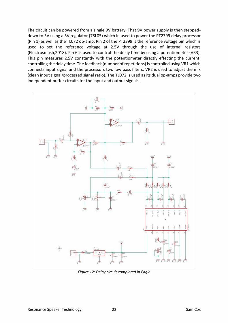
The circuit can be powered from a single 9V battery. That 9V power supply is then stepped-down to 5V using a 5V regulator (78L05) which in used to power the PT2399 delay processor (Pin 1) as well as the TL072 op-amp. Pin 2 of the PT2399 is the reference voltage pin which is used to set the reference voltage at 2.5V through the use of internal resistors (Electrosmash,2018). Pin 6 is used to control the delay time by using a potentiometer (VR3). This pin measures 2.5V constantly with the potentiometer directly effecting the current, controlling the delay time. The feedback (number of repetitions) is controlled using VR1 which connects input signal and the processors two low pass filters. VR2 is used to adjust the mix (clean input signal/processed signal ratio). The TL072 is used as its dual op-amps provide two independent buffer circuits for the input and output signals.
Figure 12: Delay circuit completed in Eagle

Resonance Speaker Technology 23 Sam Cox
3.2.4 Amplifier Circuit Circuit Diagram
The amplifier circuit is based around the TDA7297 IC. This is a stereo amplifier with two 15W channels. While this IC is “specially designed for TV and Portable Radio applications” its design makes it a great choice for applications such as this where audio quality is paramount. (ST,2003) This IC has a number of features built into it internally such as short circuit protection, stand-by and mute functions, thermal overload protection and an internally fixed gain. This means the circuit requires extremely few external components allowing for the finished circuit to remain compact especially in relation to other circuits tested for this project including LM386 op-amp and 12AX7 valve-based circuits.
This circuit can be run using a voltage supply of between 6 and 18V but for this purpose a 9V power supply was implemented to allow it to run off the same power supply as the delay circuit. 9V gives the amplifier ample headroom while allowing the project to run off of one standard 9V battery. This is helped further by the fact that only one of the two channels of the amplifier are being utilized for this application.
Figure 13: Amplifier schematic created in Eagle.
Resonance Speaker Technology 24 Sam Cox
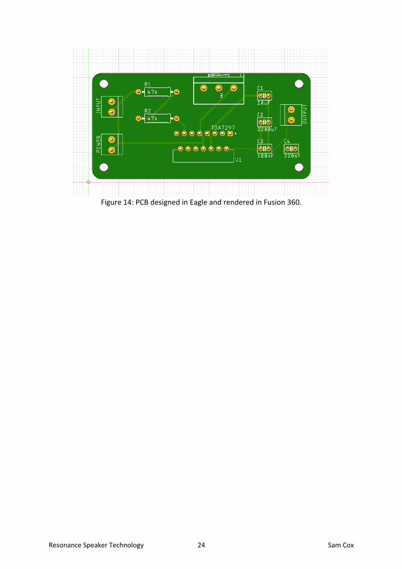
Figure 14: PCB designed in Eagle and rendered in Fusion 360.
Resonance Speaker Technology 25 Sam Cox
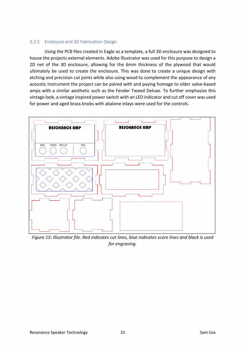
3.2.5 Enclosure and 3D Fabrication Design
Using the PCB files created in Eagle as a template, a full 3D enclosure was designed to
house the projects external elements. Adobe Illustrator was used for this purpose to design a
2D net of the 3D enclosure, allowing for the 6mm thickness of the plywood that would
ultimately be used to create the enclosure. This was done to create a unique design with
etching and precision cut joints while also using wood to complement the appearance of any
acoustic instrument the project can be paired with and paying homage to older valve-based
amps with a similar aesthetic such as the Fender Tweed Deluxe. To further emphasize this
vintage look, a vintage inspired power switch with an LED indicator and cut off cover was used
for power and aged brass knobs with abalone inlays were used for the controls.
Figure 15: Illustrator file. Red indicates cut lines, blue indicates score lines and black is used
for engraving.

Resonance Speaker Technology 26 Sam Cox
Figure 16: Illustrator cut files with colour added to aid with visibility.
Figure 17: Front view of the product with etched grill pattern

Resonance Speaker Technology 27 Sam Cox
Figure 18: Top down of unit turned off.
Figure 19: Top down of unit turned on with LED power indicator switch.

Resonance Speaker Technology 28 Sam Cox
Figure 20: Back view showing removable back panel with finger pull / external power route.
Figure 21: Back view with panel removed allowing access to battery and components.

Resonance Speaker Technology 29 Sam Cox
Figure 22: Left side view showing effects loop out (top) and stereo input/output (bottom)
Figure 23: Right side view showing effects loop in / mono input (top) and external speaker
output (bottom)

Resonance Speaker Technology 30 Sam Cox
Figure 24: I/O Configuration

Resonance Speaker Technology 31 Sam Cox
3.3 Conclusion This project has been designed with a strong focus on user experience. Every detail
from its appearance, operation and installation is centred around the user first and solving the issues that that may incur. This is evident in redesigning the way in which the output jack was modified, for example. There were many far simpler solutions to adding another connection to the guitar such as adding another guitar jack or connecting the two wires used for lead detection and letting the user remove the battery when the product was not in use. These solutions would not be practical, or user friendly and so other solutions had to be tested extensively and implemented. Using this approach, the guitar’s original jack could be repurposed by simply adding a power switch, a feature many users may want in the first place. Other examples of how this project implemented a user-first approach would be its determination to use readily available peripherals such as a standard ¼” stereo cable, a standard ¼” stereo jack should it ever fail and relying solely on 9V batteries which are used extensively in guitar peripherals such as pedals. All these choices made the manufacturing of this project more difficult due to limited grounding options regarding the stereo cable and limited power supply regarding the 9V batteries, for example. While these choices could have been overlooked in favour of simpler solutions, the user experience would have suffered and was therefore not an option.

Resonance Speaker Technology 32 Sam Cox
4 Implementation 4.1 Introduction
This section outlines the construction of the project and its evolution from early prototype to finished product. Many of the fundamental aspects are also documented in the in the Design and Testing chapters as the final product and its design are closely linked and were ultimately directed through extensive testing. The project began with commercially available circuits in order to test the projects feasibility and slowly transitioned to bespoke hardware and a unique laser-cut enclosure.
4.2 Prototype 1 The very first prototype was a feasibility prototype which involved using low power,
commercial products and connecting them to a modified acoustic guitar.
4.2.1 Process
The first stage of the fabrication process was modifying the guitar. The guitar chosen for this project did not originally come with a pickup installed and even models produced today do not include a pre-amp module. This ultimately meant a pickup and pre-amp system had to be installed. This step could be skipped if the guitar used already had a pre-amp installed but a high-quality pre-amp with volume control is crucial to this project. To install this pickup, a small hole was drilled to one side of bridge and this piezo sensor was then placed below under the bridge. This involved lowing the action of the guitar due to the increased height from the addition of the sensor. Action is a term used to describe the distance between the guitar’s strings and the fretboard and directly affects the playability of the instrument. This was corrected by sanding the bottom of the bridge using fine sandpaper on a flat surface, passing the bridge back and forth and checking the action regularly to ensure the action was not lowered too much, causing the strings to buzz undesirably. The next step was cut a hole in the side of the guitar to fit the pre-amp. This is done by marking the hole on the side of the guitar using a template, drilling a small hole in the corner of the outline and following the line with a jigsaw to remove the excess wood. This hole does not have to be perfectly accurate (and is quite hard to be completely straight-edged due to the curvature on the side of the guitar) but should allow the pre-amp to fit snuggly. The cut can be neatened with files and sandpaper but is not completely necessary as it will not be seen. Four screw-holes were also added to mount the housing.

Resonance Speaker Technology 33 Sam Cox
Figure 25: Mounting hole for pre-amp circuit.
Figure 26: Pre-amp housing mounted.
The final step was to widen the hole for the strap bottom on the bottom of the guitar to accommodate the output jack. This was done using a stepper drill bit, checking regularly for a tight fit.
Figure 27: Enlarged hole drilled for guitar jack.

Resonance Speaker Technology 34 Sam Cox
As mentioned, these previous steps could be skipped entirely if the end user planned to install the finished product on a guitar with a pre-existing pickup system. These steps obviously contradict the project’s aim to not physically alter the guitar in any way. However, this approach was chosen as a pickup system is common place for most acoustic guitars today and this pickup system is a great choice for the project. The user could also opt to use a pickup system that uses adhessive or suction cups if the guitar does not include a pickup system and they do not wish to alter their guitar or use a soundhole pickup which only involves widening the end-pin hole as outlined above. With the pickup and pre-amp installed, the output jack had to be altered to accommodate the extra connection needed for the speaker as outlined previously. To do this the two ground connections which are usually used as a power switch were soldered together. This would cause the battery to drain quickly however, so a switch was added to allow for the system to be turned off manually. This also allows the performer to turn off their instrument without having to unplug their lead. The position of the switch was determined based on a number of factors. The most important being that it had to placed somewhere the user could easily reach but would not accidentally press. The next was that it had to be added somewhere relatively flat as 3M tape would be used to allow it to be removable. Lastly, the placement relied on somewhere users are used to finding additional controls in acoustic pickup systems. These factors ultimately led to it being placed just inside the sound hole, close to where some pickup systems, notably Martin Guitars, place their volume control wheel.
Figure 28: Power switch and resonance speaker placement inside the guitar’s soundhole.

Resonance Speaker Technology 35 Sam Cox
Lastly the resonance speaker had to be added. The speaker used comes with a mounting plate that is intended to be screwed to a surface and the speaker is mounted to the plate via a threaded standoff on the center of the plate. As this project aims to avoid altering the guitar, an alternative had to be found. Through extensive testing, as outlined in the testing and research chapter to come, 3M tape was determined to be a viable solution. This placement of the speaker was determined using a loop pedal playing back audio produced by the guitar itself to recreate the final product as closely as possible and identify any areas that would cause excessive feedback. The mounting plate of the speaker was sanded with coarse sandpaper and any dust removed to create the best possible adhesion and was attached to the spot inside the guitar determined to be the most optimal (see Figure 11). The speaker was soldered to the ground and ring terminals of the guitar jack and the work on the guitar was finished. This early prototype was completed using off the shelf components including a TPA3116D2 based amplifier circuit and a number of effects pedals such as a Boss RC-3 Loop Pedal and various modulation and time-based effects such as delay, reverb and chorus pedals.
4.2.2 Features
This first prototype proved the feasibility of the project and proved resonance speaker technology could be added to electro-acoustic guitars with little alteration and no permanent changes that would otherwise de-value a guitar. While this prototype mainly involved modifying the guitar with the external circuitry prefabricated, it added multiple functions to a basic acoustic guitar.
• High quality Fishman Isys+ pickup and pre-amp added.
• Power switch added. Typically, a guitar would have to be unplugged for the pre-amp to turn off. In a live environment this would remove the need for assistance from the audio engineer who would need to disengage the audio channel first to avoid popping.
• Stereo jack modified to be input/output jack.
• Effects such as delay, reverb, chorus, and loop pedals can all be used with an acoustic guitar without the need for a traditional amplifier.
• Sound such as looped progressions sound natural from the guitar as they are produced much in the same was as plucking the strings vibrate the guitar body.
• Acoustic guitar can be made audibly louder.
4.2.3 Issues
There were several issues with this early prototype. Firstly, the amplifier circuit was not fully reliable as it could often produce excessive feedback caused by interference when set to certain parameters. Another issue was the reliance on circuits and effects not created specifically for this project not only making some components such as the amplifier less suited but also removing making the project much to small in scope. All connections (not including the guitar’s finalised internals and the stereo cable input/output) were also connected using block terminals, crocodile clips and solder joints. The final product would have to rely on standard ¼” audio jacks for audio connections and 9V DC barrel jacks for power connections.
Resonance Speaker Technology 36 Sam Cox
4.2.4 Resolution of Issues
In order to combat the instability of the amplifier circuit, a number of amplifier and pre-amp configurations were tested (as outlined in the Testing chapter) and ultimately a more optimized circuit was used for the project in a later prototype. This involved creating a custom amplifier circuit for the project and a delay circuit was also integrated into the project to alleviate some of the reliance on external guitar pedals. The final project also incorporated improved connections such as ¼” mono and stereo jacks and DC barrel jacks to make it more user friendly.
4.3 Prototype 2 This prototype involved the addition of a delay circuit into the project and the basic
design of the final enclosure including the addition of ¼” jacks for input and output.
4.3.1 Process
This prototype was fundamental in directing the final design of the project. Due to the pandemic, on campus facilities such as 3D printers and laser cutters were either inaccessible or only available in extremely short windows of time that did not line up with the progress of this project. To create a rough design for the final prototype a clear plastic box was used a basic enclosure.
The first step was to add the amplifier circuit used in the first prototype as the final amplifier was still in testing. A mounting hole for the amplifier’s potentiometer was drilled using an appropriately sized drill bit and the small circuit was mounted to the plastic enclosure.
After testing other effects such as distortion, delay was the effect chosen to be integrated into this project due to its versatility and due to the fact reverb and delay effects occur naturally in large spaces and therefore would be more appropriate for an acoustic instrument. A delay circuit PCB was purchased online for this prototype. This PCB was used as the final PCB would need to be fabricated and take some time to arrive. The PCB purchased came with all the components needed to complete the circuit separately which aided greatly with the transition to working from home as the abundance of resources found in the lab such as resistors and capacitors were no longer available due to the pandemic. With all the components soldered to the PCB, the delay circuit was ready to be added to the enclosure. Similarly to how the amplifier circuit was mounted, three holes were drilled for the circuits three potentiometers (mix, feedback, and delay). The pots could then be secured to the enclosure with their included nuts.
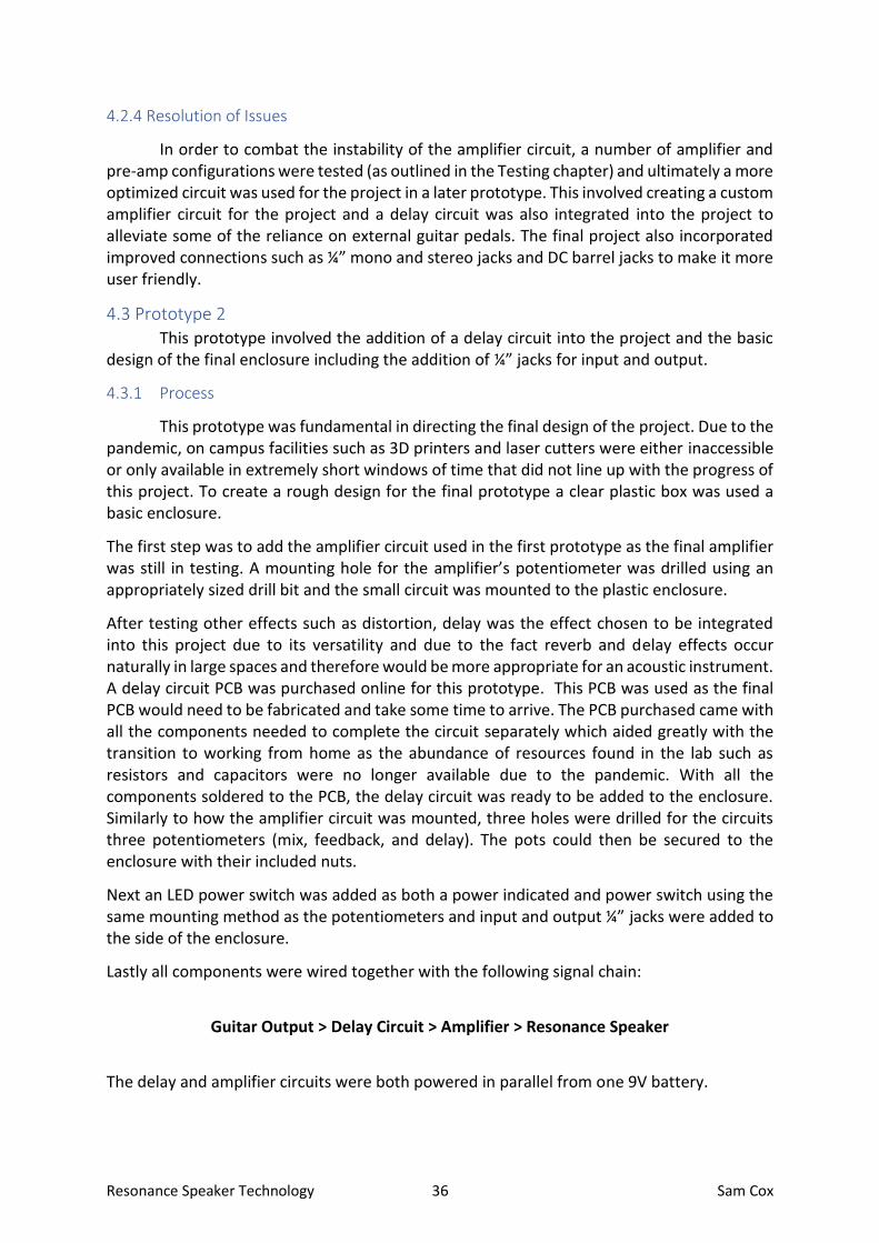
Next an LED power switch was added as both a power indicated and power switch using the same mounting method as the potentiometers and input and output ¼” jacks were added to the side of the enclosure.
Lastly all components were wired together with the following signal chain:
Guitar Output > Delay Circuit > Amplifier > Resonance Speaker
The delay and amplifier circuits were both powered in parallel from one 9V battery.

Resonance Speaker Technology 37 Sam Cox
Figure 29: Prototype enclosure top-down shot.
Figure 30: Prototype enclosure side view.

Resonance Speaker Technology 38 Sam Cox
4.3.2 Features
This prototype had several features that would be carried over to the final enclosure. The top mounted potentiometers and vertical design reminiscent of a full-sized amplifier are important in demonstrating what the product does visually and distinguishing it from standard guitar pedals. It avoids the traditional stomp box design and foot switch to prevent confusion and accidental switching. It also incorporates a switch with a valve-amp aesthetic that houses a red LED within the tip of the switch and is instantly shut off if the switch cap is closed. This also ensures the product is turned off when not in use.
4.3.3 Issues
The main issue with this prototype was its power consumption. At full volume, the power supply could become unstable, and the system could turn off. Another issue was the enclosures reliance on a mono ¼” jacks requiring a stereo cable with a Y split to be used.
4.3.4 Resolution of Issues
To allow a standard stereo cable to be used, the final enclosure features a stereo jack acting as the input and output jack for the guitar. The guitars output is then connected to a mono ¼” jack which acts a further output for effects pedals. A final ¼’ mono jack acts as an input to the delay and amplifier circuit, allowing effect pedals to be connected before the delay circuit. This adds what is essentially an effects loop to the unit without the need for additional cabling or proprietary solutions. Audio is then processed by the delay and amplifier circuits before being sent back to the stereo jack connected to the guitar and causing the resonance speaker to vibrate.
To make the circuit more stable regarding power, two options were found. The circuit could be powered off one higher quality 9V battery or two lower quality 9V batteries in series. One cheaper 9V battery could be used but as the battery began to die the circuit would become increasingly unstable. Two separate wiring harnesses were created to allow for either option. In this context, the batteries quality is being determined is relation to its capacity and maximum output.
4.4 Prototype 3 This final prototype involved the manufacturing of the final circuitry, interface, and
enclosure for the project.
4.4.1 Process
Following extensive testing, a final design for the amplifier circuit was created. The circuit utilises the TDA7297 IC which is a dual bridge amplifier with two 15W channels. This IC is designed for TV and radio applications and is therefore the perfect fit for a project such as this where audio quality is integral to the project’s success. As this IC is not intended for hobbyists, its pins are staggered meaning it cannot be used in a breadboard for testing. The IC was instead soldered directed to two pieces of Veroboard to allow for the staggered pitch. The circuit is based on a stereo amplifier design found online (Xtronics, 2012). With the final

Resonance Speaker Technology 39 Sam Cox
circuit soldered and tested, PCBs were designed for both the final amplifier and delay circuits and sent for manufacture by Seeed Studios.
With the PCBs designed in Eagle, exact measurements could be taken allowing for an extremely accurate enclosure to be designed in Adobe Illustrator to be made using laser cut 6mm plywood. This Illustrator file was sent to TechCreate based in Kildare to be laser cut due to the restricted access to on-campus facilities. The final enclosure was sanded to remove any burnt sections from the laser cutting process and was treated with carnauba wax to give some protection while allowing it to gradually age over time like older valve-amps such as a Fender Tweed Deluxe which gradually darken as they oxidize.
The same holes were then drilled for the volume, mix, feedback, and delay potentiometers as with the last enclosure, however due to the 6mm thickness of the plywood they had to be recessed slightly with a larger drill bit to allow the nut to secure to the threaded section of the potentiometer’s shaft. Holes for the stereo input jack and effects loop jacks were also drilled while an additional ¼” jack was added as an additional output jack for external speakers including resonance speakers.
A removable back panel was also added to allow the user to access the battery connection and is secured using Velcro. Initially magnets were considered due to minimise movement of the back panel and give a more premium experience. However, further testing would have been needed to ensure magnetic interference would not cause an issue with the complex audio circuitry and Velcro was instead used to minimise potential issues. The internals are accessible via a moderately sized hole used to pull the back cover off. While a handle was initially considered to prevent dust from entering the enclosure, this option allows a 9V power supply to be feed through the hole should the player which to uses a mains power supply instead of batteries.
In relation to 9V power, the system has a 9V barrel connection that accepts standard 9V battery packs and power supplies. In order to allow for greater capacity for long performances and to allow for higher power consumption if the amp is really being pushed, a 9V battery pack was created that allows for two 9V battery packs in parallel.
Finally, an external speaker add-on was created by soldering a female ¼” jack to an 8-ohm resonance speaker. This was finished off with heat shrink tubing to both add support and add a more professional appearance. A female jack was added to allow traditional ¼” guitar cables to connect the speaker to the system so that the user could use any length cable and therefore place the speaker wherever they wished. This external speaker also adds the possibility of using any audio source with the system and also allows the system to be connected to any suitable speaker or amplifier.

Resonance Speaker Technology 40 Sam Cox
4.4.2 Features
This prototype added a number of quality-of-life improvements and finalised the design of the project. The finished enclosure is striking yet simple and recreates the look of a traditional amplifier in a much smaller form factor. Some of the additional features added in this revision were:
• Handle created using a custom length cable connecting the effects loop jacks.
• Further output options – external speakers, resonance speakers or headphones can be connected. Could also be connected to a high-powered portable speaker via 3.5mm or Bluetooth adapter to increase volume further.
• Bespoke enclosure created.
• External speaker add-on created.
• Can be powered using one 9V battery, two 9V batteries in series for additional capacity and stability (using modifier battery pack created) or via 9V DC power supply.
4.4.3 Issues
The biggest issue faced was the custom PCBs being delayed. They were both ordered in early February but due to a number of issues including Chinese New Year, difficulties creating the custom ground planes implemented to reduce noise, pandemic related issues and shipping issues resulting from the Suez Canal blockage, the PCBs have not arrived as of writing (mid-April). This also has consequences for the layout of the potentiometers as the positioning was etched into the plywood precisely following the PCB design.
Another issue was the strain placed on the components used to bridge the two veroboards used for the amplifier circuit prototype. The pressure placed on both the components and the copper tracks ultimately resulted in the circuit no longer function adequately.
4.4.4 Resolution of Issues
After discussing all options with the project supervisor, it was decided to use the Veroboard circuit and blank delay circuit PCB (now populated with soldered components) purchased from eBay to complete the project. The positioning of the delay circuits potentiometers was calculated and had to be slightly repositioned on the enclosure as it had been designed for the custom PCBs which had not yet arrived. This created a relatively seamless look with the dials slightly off-centre to the outside rings etched into the wood.
The amplifier circuit was rebuilt to be far more compact and used a different technique to cut the Veroboard to allow the two pieces to align seamlessly without a gap, removing unnecessary pressure from the components and copper tracks.
The one drawback to this solution was if the final PCBs did arrive in time, they could not be added retro-actively as new holes had been drilled that were not compatible with the PCB layout.

Resonance Speaker Technology 41 Sam Cox
5 Testing & Results 5.1 Introduction
This chapter will outline the vast array of tests carried out in relation to the project, their results and how the conclusions made from these tests shaped further investigations and the final project as a whole. This testing includes circuit simulation, hardware testing, schematic and PCB testing and audio analysis.
5.2 Tests & Results
Initial testing was carried out using the analog electronic circuit simulation tool LTspice and the PCB and schematic design tool Eagle. This early testing was used to establish the direction of the project and ensure it was feasible. After much of this early testing was complete the project moved to a more hardware-based approach. Due to the pandemic, there was extremely limited access to the college and facilities and therefore limited the scope of the testing to a certain degree. To test the basic functionality of any of the hardware components involved in this project a few workarounds had to be engineered. Without the use of a dedicated calibrated signal generator, a 9V signal generator was created using a kit that provided an enclosure, PCB and components. Similarly, without access to an oscilloscope a few different methods had to be used. A 9V digital multimeter was used to measure input and output voltages where necessary while an Android app that provides audio spectrum analyzes and decibel readings called Spectroid was used to find frequency responses and test the gain findings captured from the multimeter readings. These results are of course unscientific in nature but were used as an additional tool to help test and direct the project in addition to other methods such as software simulation and subjectively testing audio aurally. 5.2.1 Distortion Circuit
As the premise of this project revolves around letting guitar players incorporate effects pedals into their acoustic guitar, building an effects pedal was essential to allow the player to quickly experience and understand the product immediately. By incorporating a limited number of effects into the unit the player would not need to bring additional equipment with them, making the product more portable.
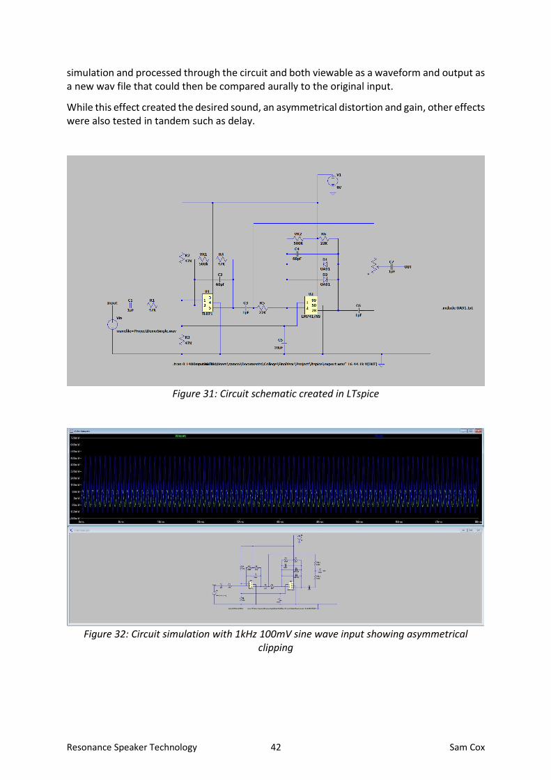
The first effects pedal tested was a distortion effect based around the TL071 and LM741 ICs and was constructed using a schematic from Advanced Projects for The Electric Guitar (Chatwin, 1996). This circuit was chosen as the distortion or overdrive effect is synonymous with the electric guitar and is a sound not often associated with the acoustic guitar, especially without an external amplifier. This would quickly demonstrate to the user the potential of the product.
As mentioned in the research chapter, similar products such as the ToneWood Amp have experimented with distortion effects in the past but ultimately removed the effect from their products by default and allowing the user to install the effect separately if they so choose.
For this test, several samples were recorded from the guitar’s pickup output. This was done using a Focusrite 2i2 interface using the digital audio workstation (DAW) Reaper. This audio was then rendered as a lossless wav audio file. That audio was then imported into the Ltspice
Resonance Speaker Technology 42 Sam Cox
simulation and processed through the circuit and both viewable as a waveform and output as a new wav file that could then be compared aurally to the original input.
While this effect created the desired sound, an asymmetrical distortion and gain, other effects were also tested in tandem such as delay.
Figure 31: Circuit schematic created in LTspice
Figure 32: Circuit simulation with 1kHz 100mV sine wave input showing asymmetrical clipping

Resonance Speaker Technology 43 Sam Cox
Figure 33: Circuit simulation with guitar audio used for input.
5.2.2 Pre-Amplifier Circuit
While several amplifier circuits were tested for this project many of them performed sub-optimally. One approach to combating the poor performance of these circuits was to implement a pre-amplifier circuit. This would allow the gain of the amplifier circuit to be reduced significantly to reduce interference or conversely allow the amplifier circuit to output a slightly louder signal. This approach was investigated as circuits based around ICs traditionally used for these types of projects, such as the LM386, can be quite sensitive to interference and distort signal at higher gain values. A pre-amplifier circuit is not objectively necessary for this project as the project is orientated around acoustic guitars with onboard pre-amplifiers. However, the addition of a pre-amplifier would allow more flexibility in terms of sound and allow guitars without pre-amps such as standard electric guitars to be used more seamlessly. Guitar amps traditionally used vacuum tubes to amplify the guitars output. Many modern amplifiers today do not use valve technology and instead rely on integrated circuits (this form of amplifier is known as a solid-state amplifier). However, valve amplifiers are still used extensively especially in professional applications and are highly sought after in both guitar amps and pedals. Vacuum tubes naturally have a unique frequency response, compression factor and distortion that can only be simulated by solid state amps. This sound is highly responsive and is determined by a number of factors including the input volume and bias. Typically, a dual triode such as the 12AX7 requires 250V AC but can be modified to run on much lower voltages. This project investigated powering that particular tube using 9V or 18V (using two 9V batteries in series). This reduced voltage was crucial as the project is intended to be highly portable and had to be able to run of the same 9V batteries used for guitar pedals and acoustic guitar pre-amps.

Resonance Speaker Technology 44 Sam Cox
The circuit was first tested using Ltspice following a low voltage circuit demonstrated by a YouTube user using a 12V leisure battery. (JohnAudioTech, 2013) This simulation showed favorable results and functioned using both 9V and 18V supplies. The one issue with simulating dual triodes like the 12AX7 in Ltspice is that it assumes adequate power is provided to the valves heating filament by default and does not allow a battery to be connected to the filament without modifying the part significantly. Similarly, to the distortion circuit outlined previously, the same guitar recording was processed using Ltspice in order to simulate the circuits output. When the circuit was recreated using the authentic hardware, the circuit was significantly less stable than the circuit simulation. The circuit was tested using a 9V battery, two 9V batteries in parallel for greater current, as well as two 9V batteries in series to produce 18V. This instability is likely due to the limited current provided by 9V batteries as the YouTube video cited proves the circuit is functional using just 12V but was tested using a leisure battery which can produce much higher currents over longer durations due to its increased capacity. By using higher quality 9V batteries such as an Ultra+ Premium Alkaline from Energizer it was possible to record a more consistent 9V at higher currents using a digital multimeter but proved the current draw was to significantly, quickly discharging the battery making the circuit unstable and ultimately making it unsuited to this particular project.
Figure 34: 12ax7 pre-amp schematic created in LTspice.

Resonance Speaker Technology 45 Sam Cox
Figure 35: Simulation showing 1kHz 100mV sinewave input and inverted 3V output.
Figure 36: PCB designed in Eagle
Resonance Speaker Technology 46 Sam Cox
5.2.3 Amplifier Circuit Prototypes
The core of this project is the amplifier section. As mentioned previously, a number of amplifier circuits were testing including numerous LM386 based circuits. Initially the feasibility of the project was established by using off-the-shelf amplifier circuits to quickly determine potential issues and direct the project. This included numerous LM386 based boards and a TPA3116D2 board. These were tested using the following basic signal chain, testing a number of different effects pedals both individually and in series.
Acoustic Guitar Output > Effects Unit/s > Amplifier Circuit > Resonance Speaker
While this quickly established the basic idea was possible, it also outlined a number of issues. The key issue was volume. While the circuits did amplify the sound significantly, amplifier circuits had to be stacked or an effects pedal with a form of signal boosting was needed to get the required output volume. In order for this project to be successful, the output volume must be audibly as loud as the guitar itself in order to allow loop pedals and delay effects to work convincingly. The exact gain factor needed is not possible to determine as it also depends on a number of factors such as the volume of the guitar acoustically, frequency response of the amplifier and even the positioning of the resonance speaker inside the guitar. The LM386, for example, is internally set to have a gain factor of 20 which is significantly lower than the approximate gain of 40 needed which was determined aurally using a dB meter and converting to gain.
Another potential issue was feedback. Feedback had to be completely minimized in this project due to the proximity of the resonance speaker to the piezo element inside the guitar. However, the TPA3116D2 circuit in particular was quite susceptible to feedback loops caused by interference rather than the speaker and piezo. This was determined as it was still possible to recreate without the piezo pickup activated.
This led to the LM386 being reinvestigated using a small modification to allow the gain to be adjusted to up to a factor of 200. This circuit was simulated as shown below in Figure 10 and produced promising results. This circuit still showed some potential issues, however. When the circuits gain was increased, the audio began to slightly distort asymmetrically as well as clip at higher voltages. When recreated on a breadboard the circuit did in fact clip with some asymmetrical distortion as the simulation showed as well as picking up some interference at higher gain values. To potentially solve this issue, a pre-amplifier circuit was introduced as mentioned previously.
Resonance Speaker Technology 47 Sam Cox
5.2.4 Final Amplifier Circuit
Up to this point ICs used by guitarists, makers and hobbyists such as the LM386 had not yielded optimal results. These ICs are used for a number of reasons including availability, price, ease of use and due to their ubiquity in this area of technology due to how long they have been in circulation. With this in mind, an IC not commonly used in these applications was tested. This IC was the TDA7297 which is a dual bridge amplifier with two 15W channels. This IC is designed for professional applications such as TV and radio making it ideal for an application such as this where audio integrity is fundamental whereas chips such as the LM386 are often used to their own advantage for their tendencies to distort clean guitar signal. While this IC is a dual channel amplifier, only one channel was needed for this application. Due to the asymmetrical pin layout, this chip does not fit on breadboards or Veroboard. However, two Veroboards were used to solve this issue, with one used for each side of the chip also alleviating the need to break the copper traces that would have otherwise connected the two rows of pins.
This IC is a dual bridge amplifier with two 15W channels. (ST, 2003) It accepts supply voltages from 6 to 18V which allowed the circuit to be tested with both a signal 9V battery as well as two 9V batteries in series giving a supply voltage of 18V. As the circuit has a fixed gain value of approximately 32dB, the additional headroom provided by the 18V power supply was not deemed necessary.
This IC proved to be well suited to the project for a number of reasons. The IC has enough gain for the application, is well priced, extremely easy to work with due to the minimal number of external components needed (with the exception of the staggered pitch making it difficult to implement without a PCB) and does not have the same tendency to feedback that was found in the LM386 circuits. This is particularly unexpected as the pickup system in this guitar is fundamentally similar to a single coil pickup similar to those found in a Fender Stratocaster. These pickups, as opposed to pickups such as humbuckers found in Gibson Les Pauls, have a tendency to feedback particularly when in close proximity to the amplifier such as in this case where the speaker and pickup are millimetres apart. Furthermore, these pickups tend to be susceptible to 50 or 60 cycle hum caused by interference caused by powerlines (powerlines operate at 50Hz in Ireland often resulting in 50 cycle hum).
There was not a set amount of gain required for this project as its use case varies greatly. The core idea was that resonance speaker would recreate the guitars audio at approximately the same volume as the guitar would produce acoustically, therefore making loop pedals and extreme delay effects hugely effective. In the 3 different guitars this guitar has been tested with the volume has been exceptionally louder than the volume of the guitar acoustically but ultimately it depends on the volume of the guitar acoustically, the positioning of the resonance speaker, the impedance of the resonance speaker (4-ohm resonances speaker significantly quieter than an 8-ohm resonance speaker), the output of the guitars pre-amp and how the user intends to use the system.

Resonance Speaker Technology 48 Sam Cox
5.2.5 Delay Circuit
This project’s main aim was always to allow guitar players to add effects to their
acoustic guitar sound. This was tested from the very start, first with the aid of the software
simulation tool LTspice and later with physical hardware. Multiple guitar effects pedals and
multi-effects pedals were tested with the initial prototype and delay was ultimately
determined to be the most important effect to incorporate into the project. Through research
it was determined the PT2399 IC was the best suited chip for this application. This chip is used
by hobbyists to create reverb, delay, echo and chorus effects but is also used in professional
applications and can be found in many boutique guitar pedals such as the Space Spiral by
EarthQuaker Devices.
This chip can allow for delays as short as 30ms and as long as 340ms allowing it to provide sounds from reverb like delay to cathedral style echo effects. This chip is also extremely efficient using just 30mA at max load (Electrosmash, 2018). While the chip needs just 5V DC to operate, a 9V battery with a 5V voltage regulator was used in this case to allow both the amp and delay circuit to be operated using a single power source. As outlined previously, a blank PCB designed for this application was purchased and populated for testing. With excellent audio quality and performance, a final PCB was designed in Eagle and sent to Seeed Studios for manufacture. The full circuit layout is explored in the design chapter.
Figure 37: Delay PCB purchased for testing (eBay, 2021).
Resonance Speaker Technology 49 Sam Cox
5.3 Interpretation of Results Following the testing, both hardware and software based, of the multiple approaches
taken to amplify the guitars signal, it was determined that a TDA7297 based amplifier circuit would be better suited to the project than a two-stage amplifier circuit such as the 12AX7 pre-amp and LM386 amplifier initially proposed. The TDA7297 was not only more reliable and consistent and consumed significantly less power than the other option, but it also produced a much better-quality audio signal with noticeably less interference and no hard-clipping.
In terms of effects both the distortion and delay circuit performed extremely well in
this use-case, but the delay circuit was chosen due to its wider range of applications. Furthermore, this product opens up the opportunity for players to incorporate any effects pedal, including distortion, into their acoustic guitar sound. Therefore, given the nuance surrounding distortion and overdrive pedals and the sheer variety available, it was determined the best option was to allow the player to choose what type of distortion they would like to add to their sound through the use of effects pedals.
5.4 Conclusions Following the expansive testing carried out, both hardware and software, of effects
and amplifier circuitry, it was ultimately determined that the most appropriate configuration
for this project was the PT2399 delay circuit and TDA7297 amplifier circuit to give the user
the most tonal possibilities while keeping the circuitry as minimal as possible and allowing for
great battery life. While other options were explored such as adding DTDP switching to allow
the user to select the audio output, additional level controls such as adding an input and
output control for the amplifier circuit or adding an independent power and bypass switch to
the delay circuit, it was decided to keep the product as minimal and user friendly as possible.
The omission of these features did not take away from the final product as the delay circuit
for instance can be set to output dry signal and, in this case, works as a buffer circuit and uses
significantly less power than at max load. Similarly, the lack of audio output switching does
not prevent the user from selecting their preferred output path and in fact adds the potential
to allow for two 8Ω resonance speakers to be used in parallel. The user can opt to only use an
external speaker by connecting any guitar, including the modified acoustic used for this
project, to the effects loop input.
Resonance Speaker Technology 50 Sam Cox
6 Conclusion In conclusion, this report has outlined the detailed research, testing and
implementation carried out over the course of the project. While the project’s aim appears
novel, incorporating a resonance speaker into an acoustic guitar, the project was ultimately
directed by its requirements and necessary limitations. The product can be installed in any
electro-acoustic guitar with minimal work with no permanent modifications needed and adds
the potential to use any audio effect with an acoustic guitar such as flanger, chorus or
distortion as well as the built-in delay/reverb. The product has been designed from the ground
up to run on a single 9V battery and is truly portable. Furthermore, it requires only one stereo
cable to be used with guitar modified in the same manner as outline while also allowing for
any guitar or audio source to be connected as an input and allowing for any speaker, including
a purpose-built external resonance speaker, to be connected as an output device via ¼” TS
cable.
This project has proven that this technology can be added to any acoustic guitar at a fraction
of the cost of its rivals while bringing greater functionality such as compatibility with standard
guitar pedals including loopers for solo artists. The project has added numerous features to
widen the scope of use cases such as the potential to use resonance speakers externally,
allowing any surface, and by extension utilising its unique acoustic properties, to become a
speaker. Other features such as a choice of power options (9V battery, two 9V batteries for
greater capacity or 9V power supply) make the product extremely versatile for larger cohort
of musicians.

Resonance Speaker Technology 51 Sam Cox
Appendix

Resonance Speaker Technology 52 Sam Cox

Resonance Speaker Technology 53 Sam Cox

Resonance Speaker Technology 54 Sam Cox

Resonance Speaker Technology 55 Sam Cox

Resonance Speaker Technology 56 Sam Cox

Resonance Speaker Technology 57 Sam Cox

Resonance Speaker Technology 58 Sam Cox

Resonance Speaker Technology 59 Sam Cox

Resonance Speaker Technology 60 Sam Cox

Resonance Speaker Technology 61 Sam Cox

Resonance Speaker Technology 62 Sam Cox

Resonance Speaker Technology 63 Sam Cox

Resonance Speaker Technology 64 Sam Cox
References ABRSM. (2014). Making Music. Retrieved from https://gb.abrsm.org/en/making-music/4-the-statistics/#:~:text=An%20encouraging%2085%25%20of%20children,fewer%20than%20half%20of%20adults
Arduino. Arduino - Introduction. Retrieved October 25, 2018, from https://www.arduino.cc/en/Guide/Introduction
Chatwin, J. (1996). Advanced Projects for The Electric Guitar. Babani Electronics Books
Disc Makers. (February 10th, 2016). Guitar Effects Pedals and the Evolution of Music. Retrieved from https://blog.discmakers.com/2016/02/effects-pedals-and-the-evolution-of-music/ eBay. (2021). DIY KIT FOR GUITAR DIGITAL AUDIO ECHO DELAY PT2399 MIX FEEDBACK DELAY. Retrieved from https://www.ebay.ie/itm/DIY-KIT-FOR-GUITAR-DIGITAL-AUDIO-ECHO-DELAY-PT2399-MIX-FEEDBACK-DELAY/223055205453?ssPageName=STRK%3AMEBIDX%3AIT&_trksid=p2057872.m2749.l2649
Electrosmash. (2018). PT2399 Analysis. Retrieved from https://www.electrosmash.com/pt2399-analysis
Guitar. (April 25th, 2018). Gibson’s Woes Continue with $50 Million Robot Tuner Lawsuit. Retrieved from https://guitar.com/news/gibsons-woes-continue-with-50-million-robot-tuner-lawsuit/
HowStuffWorks. (2012). How Vibration Speakers Work. Retrieved from https://electronics.howstuffworks.com/gadgets/audio-music/vibration-speakers.htm
JohnAudioTech. (2020). 12AX7 Stereo Tube Preamp Using 12V. [Video] YouTube. https://www.youtube.com/watch?v=BTrUJC_vpyc&t=123s
K&K. (2020). What is the Difference Between an Undersaddle and a Bridge Plate Pickup? Retrieved from https://kksound.com/support/pickups101/bridgeplatepickup.php
LG Magazine. (2018). LG G7 THINQ Puts the Boom Back into the Boombox Speaker. Retrieved from https://www.theverge.com/2019/2/13/18224394/lg-g8-thinq-oled-speaker-quad-dac-boombox
LTspice. (2020). Design Center. Retrieved from https://www.analog.com/en/design-center/design-tools-and-calculators/ltspice-simulator.html

Resonance Speaker Technology 65 Sam Cox
ST. (2003). TDA7297. Retrieved from https://www.st.com/resource/en/datasheet/tda7297.pdf
Stringjoy. (June 8th, 2019). Acoustic Pickup Types Explained. Retrieved from https://www.stringjoy.com/acoustic-guitar-pickup-types-explained/
Tonewood Amp. (2015). What is it? Retrieved from https://www.tonewoodamp.com/
Washington Post. (2017). The Death of the Electric Guitar. Retrieved from https://www.washingtonpost.com/graphics/2017/lifestyle/the-slow-secret-death-of-the-electric-guitar/
Xtronics. (2012). Stereo Power Audio Amplifer with TDA7297 -2 X 15 Watts. Retrieved from https://xtronic.org/circuit/amplifier/circuit-stereo-power-audio-amplifier-using-tda7297-2-x-15-watts-mute-and-stand-by-optional-easy-to-assemble/
Yamaha. (2017). TransAcoustic Guitars. Retrieved from https://europe.yamaha.com/en/products/musical_instruments/guitars_basses/ac_guitars/ta_series/features.html#product-tabs