Acoustic Cell Separation Based on Density and Mechanical ...
9
Transcript of Acoustic Cell Separation Based on Density and Mechanical ...

Yuliang XieDepartment of Chemical Engineering,The Pennsylvania State University,
University Park,State College, PA 16802
Zhangming MaoDepartment of Engineering Science and
Mechanics,
The Pennsylvania State University,University Park,
State College, PA 16802
Hunter BachmanDepartment of Mechanical Engineering and
Materials Science,Duke University,
Durham, NC 27708
Peng LiDepartment of Engineering Science and
Mechanics,The Pennsylvania State University,
University Park,
State College, PA 16802
Peiran ZhangDepartment of Mechanical Engineering and
Materials Science,Duke University,
Durham, NC 27708
Liqiang RenDepartment of Engineering Science and
Mechanics,The Pennsylvania State University,
University Park,State College, PA 16802
Mengxi WuDepartment of Mechanical Engineering and
Materials Science,
Duke University,Durham, NC 27708
Tony Jun Huang1
Department of Mechanical Engineering andMaterials Science,
Duke University,Durham, NC 27708
e-mail: [email protected]
Acoustic Cell Separation Basedon Density and MechanicalPropertiesDensity and mechanical properties (e.g., compressibility or bulk modulus) are importantcellular biophysical markers. As such, developing a method to separate cells directlybased on these properties can benefit various applications including biological research,diagnosis, prognosis, and therapeutics. As a potential solution, surface acoustic wave(SAW)-based cell separation has demonstrated advantages in terms of biocompatibilityand compact device size. However, most SAW-reliant cell separations are achieved usingan entangled effect of density, various mechanical properties, and size. In this work, wedemonstrate SAW-based separation of cells/particles based on their density and compres-sibility, irrespective of their sizes, by manipulating the acoustic properties of the fluidicmedium. Using our platform, SAW-based separation is achieved by varying the dimen-sions of the microfluidic channels, the wavelengths of acoustic signals, and the propertiesof the fluid media. Our method was applied to separate paraformaldehyde-treated andfresh Hela cells based on differences in mechanical properties; a recovery rate of 85%for fixed cells was achieved. It was also applied to separate red blood cells (RBCs) andwhite blood cells (WBCs) which have different densities. A recovery rate of 80.5%forWBCs was achieved.[DOI: 10.1115/1.4046180]
Keywords: surface acoustic wave (SAW), cell separation, cell density, cell mechanicalproperties
Introduction
Cell density and mechanical properties (e.g., bulk modulus orcompressibility) are important for cellular phenotyping, diagnosis,and prognosis [1–4]. For example, changes in the densities of redblood cells (RBCs) can be an indicator of membrane loss, abnor-mal surface-to-volume ratios, and/or alterations to the intracellularion count or water content [5]. Additionally, RBCs have a greaterdensity than white blood cells (WBCs) due to the presence of
highly concentrated hemoglobin; this density difference providesa criterion for cell separation. The abnormal mechanical proper-ties of cells can often be linked to inherited genetic disorders(e.g., sickle cell anemia and hereditary spherocytosis), noninfec-tious diseases (e.g., diabetes and cancer), or infectious diseases(e.g., malaria) [6–8]. Given these facts, methods that can rapidlyseparate cells of different densities, as well as mechanical proper-ties, are critical for detecting diseases such as cancers and infec-tions, and they also benefit many applications in biology,chemistry, and medicine [9–14].Density-based cell separation is conventionally achieved with
centrifugation [15]. Despite its robust performance, the process ofcentrifugation exerts strong rotational forces on cells which might
1Corresponding author.Manuscript received November 5, 2019; final manuscript received December 30,
2019; published online February 28, 2020. Assoc. Editor: Victor H. Barocas.
Journal of Biomechanical Engineering MARCH 2020, Vol. 142 / 031005-1CopyrightVC2020 by ASME
Downloaded from https://asmedigitalcollection.asme.org/biomechanical/articl
e-pdf/142/3/031005/6489136/bio_142_03_031005.pdf by Duke University, ys
[email protected] on 18 July 2020

alter their natural functionality, and requires bulky instrumenta-tion. On the other hand, separating cells based on differences inmechanical properties usually relies on interactions between cellsand cell-sized structures (e.g., pores, pillars, curves, and narrowchannels) in either bulk or microfluidic devices [16–22]. For exam-ple, Yang et al. [23] demonstrated fresh/fixed RBC separation bymanipulating the trajectories of either subgroup after passingthrough a narrow channel while suspended in a viscoelastic media;Holmes et al. [24] showed that RBCs treated with different concen-trations of glutaraldehyde display a varied displacement in a deter-ministic lateral displacement device. Hvichia et al. utilized cell-sized microfluidic channel to separate circulating tumor cells fromWBCs 25], which features larger deformability (i.e., softer) thanWBCs. Nevertheless, using devices with numerous cell-sized struc-tures that contact cells increases the risk of clogging or contact-based damage to the cells. Therefore, it is desirable to develop acell density and mechanical property-based separation method thatis compact, noncontact, and does not disrupt cellular functions.
The surface acoustic wave (SAW) [26–28] has demonstratedgreat momentum in cell separation [29–37] due to its compact, non-contact, and biocompatible operation [38–42]. Traditionally, to sep-arate cells in an acoustofluidic (i.e., the fusion of acoustics andmicrofluidics) device, a SAW field is established in a two-dimensional (2D) plane that is parallel [43] or tilted [44] withrespect to a microfluidic channel [45,46]; cells passing through thisSAW field deflect in response to acoustic radiation forces [47,48].The most widely used SAW separation mechanisms are based onan integrated effect of cell size, density, and mechanical properties[49] in which the cell size is often the dominant factor. As an exam-ple, since the range of densities present in a cell population may bevery narrow [2], the cellular mass and volume, which may vary byas much as 50%, have a much greater impact on distinguishing dif-ferent cell types during acoustic radiation force-based separation.However, utilizing a method that is heavily dependent on size maymask differences in compressibility or other mechanical propertiesthat are present between different cell types. In another case, meta-static cancer cells show a similar volume but “softer” phenotype tothat of their healthy counterparts due to the changes in thecytoskeleton structures [9,50]; in both cases, a cell’s density andmechanical properties, rather than size, may provide more appro-priate parameters to distinguish between cell populations.
In this work, we present an effort to decouple the effects of sizefrom density and other mechanical properties during acoustic cellseparation by adjusting the acoustic properties (i.e., density and/orspeed of sound) of the fluidic medium. Manipulating the fluidproperties allows us to determine whether cells equilibrate at posi-tions of pressure nodes (PNs) or antinodes (ANs). In addition,since all the cells migrate to their equilibrium positions at eitherpressure nodes or antinodes, regardless of their initial positions,this separation approach no longer requires a sheath flow to setthe initial positions of cells. To demonstrate the design, mecha-nism, and performance of our cell separation platform, we firstconducted a numerical simulation to elucidate the mechanism ofparticle/cell migration due to the acoustic radiation force. Second,we demonstrated the capability of our acoustofluidic devices inseparating polydimethylsiloxane (PDMS) and polystyrene micro-particles in water. Third, we added Ficoll to the fluidic domain tomodify its properties and separate different cell types. We demon-strated density-based (i.e., RBCs and WBCs) and compressibility(or bulk modulus)-based (i.e., paraformaldehyde-treated and freshHela cells) cell separations. With the ability to separate cells withdifferent densities and mechanical properties, the application ofour contactless, biocompatible SAW separation technology isexpected to be a powerful tool in many biological, chemical, bio-physical, and medical applications.
Methods
Materials. Ficoll (MW¼ 70 and 400 kDa) were purchased fromMillipore-Sigma (Burlington, MA). Polystyrene microparticles
with fluorescence (excitation at 480 nm; emission at 520 nm)(Warrington, PA) and 5 lm diameter were purchased from Poly-sciences, Inc. PDMS microparticles were prepared following theprotocol. A single gram of a 10:1 mixture of PDMS prepolymer tocuring agent (Sylgard 184, Dow Corning, Inc., Freeland, MI) wascombined with a 1% (w/w) sodium dodecyl sulfate solution; wesonicated this solution for 20 min to emulsify the PDMS polymerwith the sodium dodecyl sulfate, and then incubated the mixtureat 65 �C for 60 min and left it at ambient conditions for 12 h toallow curing.
Cells. Hela cells were grown in Dulbecco’s Modified EagleMedium: Nutrient Mixture F-12 (DMEM/F12) media (Fisher Sci-entific, Hampton, NH), supplemented with 10% fetal bovineserum (R&D Systems, Minneapolis, MN), penicillin (100 U/mL),and 100 lg/mL streptomycin (Mediatech, Manassas, VA). Thecell lines were maintained in T-25 cell culture flasks in a 37 �Cincubator at 5% CO2 and were cultured twice per week. Beforeeach experiment, an adherent culture was released from flasksusing 0.05% trypsin digestion (Cellgro, Corning, NY), and wasrinsed with Trypsin neutralizer solution (Life Technologies, Carls-bad, CA). After centrifugation at 800 rpm for 5 min and rinsingwith phosphate-buffered saline (PBS) buffer (1�, pH 7.4), cellswere resuspended in a PBS solution for experiments. To changethe mechanical properties of Hela cells, they were treated using4% (wt/vol) paraformaldehyde (Santa Cruz Biotechnology, Dal-las, TX) for 10 min at room temperature, then were resuspendedin a PBS solution.
Blood cells collected within 24 h of experiments were first lysedusing RBC lysis buffer for 5 min to remove most erythrocytes.WBCs were collected by centrifuging the blood at 800� g andresuspended in the same volume as the whole blood in 1� PBSsolution with 0.1% pluronic F-68. To prepare samples with prede-fined ratio between RBCs and WBCs, the suspended WBC samplewas mixed with a certain volume of whole blood.
Microfluidic Setup. Chrome-plated gold (Cr/Au, 50 A/500 A)was deposited onto a 128 deg Y-cut lithium niobate (LiNbO3)wafer (500 lm thick) that had been patterned with a photoresist,followed by a liftoff technique to form the pair of interdigitaltransducers (IDTs). The PDMS-based microchannel was fabri-cated per a standard soft-lithography and replica molding proce-dure using SU-8 photoresist. Holes were punched in the PDMSmicrochannel for inlets and outlets with a Harris Uni-Core 1.0 mmpunch. To bond the PDMS microchannel with a LiNbO3-basedSAW substrate, a plasma cleaner (Harrick Plasma, Ithaca, NY)was used to treat the components with oxygen plasma for 3 min.The PDMS microchannel was aligned and bonded to the SAWsubstrate between the IDTs. The whole device was cured for atleast 3 days in a 65 �C oven before being used in testing; this wasdone to avoid leakage between the channel and the SAWsubstrate.
We completed our testing using an inverted microscope (NikonEclipse Ti-U, Japan). To eliminate the virtual image from thedouble-side polished LiNbO3 substrate, a polarizer was placed inthe light path and adjusted to the requisite angle. Sample solutionswere prepared in 1 ml plastic syringes (Becton, Dickinson andCompany, Franklin Lakes, NJ), such that a syringe pump (neM-ESYS, cetoni GmbH, Germany) could be used to deliver the fluidinto the channel through polyethylene tubing (Becton, Dickinsonand Company). To control the flow, one pump injected samplesfrom the inlet; two other pumps were connected to the outlets forwithdrawal; and the last outlet was open. Radiofrequency signalswere generated (E4422B, Agilent, Santa Clara, CA) at desired fre-quencies and were amplified (100A250A, Amplifier Research,Souderton, PA) to generate the standing SAW fields. A CCDcamera (Coolsnap HQ2, Photometrics, Tucson, AZ) was posi-tioned facing the XY plane of the device to record the motion ofmicroparticles at 10 fps. The trajectories of particles during
031005-2 / Vol. 142, MARCH 2020 Transactions of the ASME
Dow
nloaded from https://asm
edigitalcollection.asme.org/biom
echanical/article-pdf/142/3/031005/6489136/bio_142_03_031005.pdf by Duke U
niversity, yspro16@gm
ail.com on 18 July 2020

particle separation were generated using IMAGEJ software to stackthe recorded video.
Recovery Rate. The recovery rate of a specific type ofparticles/cells collected from an outlet was calculated from thefollowing equation:
recovery rate ¼ c1v1
c0v0
(1)
where c1 is the concentration of a specific particle, v1 is the flow-rate from a specific outlet, c0 is the original concentration of par-ticles at the inlet, and v0 is the flowrate from the inlet. Therecovery rate was calculated with three experimental replicationsand represented by mean 6 standard deviation.
Viability Test. The viability of WBCs and Hela cells is testedto verify biocompatibility of the separation process. Tested cellswere immersed at the highest concentration of Ficoll which wehave used in separation experiments (30% w/w), and then flowedthrough the microfluidic channel with a flowrate of 10 lL/min andan acoustic power of �8 dBm (maximum power used in experi-ments). Cells were collected from the outlet during a 15 min oper-ation period. The WBCs were stained with propidium iodide. Ascontrol groups, viability tests were conducted on cells that wereimmersed in Ficoll without SAW, PBS without SAW, and etha-nol. In addition, Hela cells were collected at the outlets, they weretransferred to a DMEM/F12 medium and cultured at 37 �C forgrowth testing.
Numerical Methods. The SAW-induced acoustic field distri-bution and the particle motion were numerically studied usingCOMSOL MULTIPHYSICS 4.4. The SAW field was simulated with thepressure acoustics module using a frequency domain study. Parti-cle trajectories were simulated with the particle tracing for fluidicflow module. To simplify the model, the standing SAWs wereconsidered uniform along the longitudinal direction of the chan-nel; the acoustic field and the resulted particle migration in a 2Dchannel cross section were numerically investigated to simplifythe analysis of three-dimensional motion of the particles. In addi-tion, the piezoelectric substrate and the PDMS channel were notincluded in the 2D numerical model, and their physical effects onthe acoustic field in the fluid were modeled by boundary condi-tions. These simulations also solved the acoustic radiation force,the Stokes drag force, and the particles’ motion in the lateraldirection (x–z plane). Parameters used in this numerical studywere listed in Tables 1 and 2.
The governing equation for the acoustic field p in the fluiddomain was the lossy Helmholtz equation, given as [51]
x2
c2f
pþ 1þ ix 1þ bð Þlqf c2
f
" #r2p ¼ 0 (2)
where p, qf, cf, x, b, l, and i indicate, respectively, the acousticpressure, density of fluid, acoustic phase velocity of fluid, angularvelocity, fluid viscosity ratio, fluid dynamic viscosity, and imagi-nary unit. The acoustic particle velocity v (acoustic particle veloc-ity) was coupled with the acoustic pressure p via the momentumbalance equation in fluid
v ¼ � rp
ixqf
1þ ix 1þ bð Þlqf c2
f
" #(3)
This equation gave the velocity field v corresponding to a givenpressure from Eq. (2), which was solved by establishing boundaryconditions. The bottom of the 2D fluid domain was the actuationboundary of the standing SAW, which was modeled as the accel-eration of surface particles moving transversely
a ¼ �nrp
qf
1þ ix 1þ bð Þlqf c2
f
" #" #¼ n � A0x
2 e�iksx � e�iks w0�xð Þ½ �
(4)
where A0, ks, w0, and n correspond to the amplitude of SAW dis-placement, wave number of SAW, channel width, and boundarynormal vector, respectively. The other three boundaries aredefined as lossy [51] to model the acoustic pressure loss uponpropagation through the PDMS/fluid interface
n � rp ¼ ixqf
qwcwp (5)
where qw and cw are the density and the speed of sound in thewall’s material, respectively.
Once the acoustic fields p and v are obtained from the 2Dmodel, the time-averaged acoustic potential in the fluid domainand acoustic radiation force on a single spherical particle can becalculated by the following equations [52]:
U ¼ V0 f1
1
4qf c2f
Re p � p�ð Þ � f23qf
8Re v � v�ð Þ
" #(6)
Frad ¼ �rU (7)
In Eq. (6), V0 is the particle volume; qp and cp are the density andsound speed of the particle, respectively; Re is the real part of acomplex value; and the asterisk indicates complex conjugation.Two parameters in Eq. (7), i.e., f1¼ 1� (qfcf
2)/(qpcp2), and
f2¼ 2(qp�qf)/(2qpþ qf), determine the direction of the par-ticles’ motion, based on their densities and speed of sound,which is closely related with the compressibility and bulkmodulus.
Results and Discussion
Working Mechanism. The acoustofluidic cell separationdevice included a microfluidic channel for sample handling and apair of IDTs for acoustic actuation (Fig. 1(a)). The single-layermicrofluidic channel had a single inlet and three outlets. Thedimensions of microfluidic channel within the particle/cell deflec-tion region were 340 lm in width, 60 lm in depth, and 10 mm inlength. The IDT pairs were positioned parallel to the microfluidicchannel. Each IDT contained 20 pairs of electrodes each 10 mm inlength and a gap between each electrode 150 lm, yielding in anoperating frequency of 12.89 MHz (Fig. 1(b)). This operationalfrequency enabled us to establish three low pressure zones andtwo high pressure zones in the channel, as described in the follow-ing discussion.
The design of the separation system was guided by numericalstudies into the acoustic pressure distributions and particle
Table 1 Parameters of liquids and particles used in numericalsimulations
Water Polystyrene PDMS
Density (kg/m3) 997 1050 965Speed of sound (m/s) 1495 2350 1080Dynamic viscosity (Pa�s) 0.001 N/A N/A
Table 2 Parameters of SAWs used in simulations
Acoustic phase velocity of SAW (m/s) 3900Frequency (MHz) 13Amplitude of vibration of SAW (nm) 1
Journal of Biomechanical Engineering MARCH 2020, Vol. 142 / 031005-3
Dow
nloaded from https://asm
edigitalcollection.asme.org/biom
echanical/article-pdf/142/3/031005/6489136/bio_142_03_031005.pdf by Duke U
niversity, yspro16@gm
ail.com on 18 July 2020

Fig. 2 (a) Numerical studies conducted in the SAW-impacted region and outlet region. (b) The distribution ofacoustic pressure distributions in the SAW-impacted region, where a position with minimum acoustic pressure isnamed a PN and a position with maximum pressure is named a pressure AN. ((c) and (d)) The simulated trajecto-ries of acoustic negative and positive particles in the standing SAW field. (e) Simulated trajectories of particles inthe outlet region, where particles start at equilibrium positions at the end of SAW impact region, and follow lami-nar flow to each collecting outlets.
Fig. 1 (a) Schematic and (b) photo of the acoustic cell separation device
031005-4 / Vol. 142, MARCH 2020 Transactions of the ASME
Dow
nloaded from https://asm
edigitalcollection.asme.org/biom
echanical/article-pdf/142/3/031005/6489136/bio_142_03_031005.pdf by Duke U
niversity, yspro16@gm
ail.com on 18 July 2020
motions in the SAW region and outlet region of the device(Fig. 2(a)). In the SAW-impacted region, two parallel IDTs gen-erated a two-dimensional standing acoustic field in the channelthat was symmetric in the Y-direction. Aligning the microfluidicchannel and the IDTs produced two maximum acoustic pressurelines (i.e., pressure antinode lines) and three minimum pressurelines (i.e., pressure node lines). The pressure nodes werelocated at the two edges and the center of the channel, and theantinodes were located in between (Fig. 2(b)). Using our simu-lations, we showed that when randomly distributed particles oflesser density and/or bulk modulus (i.e., slower speed of sound,and larger compressibility) than those of the fluid medium areexposed to the acoustic field shown in Fig. 2(b), they will moveto the pressure antinodes (Fig. 2(c)) according to Eq. (6). Tosimplify our description of this phenomenon, particles migrat-ing to pressure antinodes were referred to as “acoustic negativeparticles.” Conversely, particles with larger density and speed
of sound than surrounding medium, referred to as “acousticpositive particles,” move to the pressure nodes (Fig. 2(d)). Wealso simulated the motion of acoustic positive/negative par-ticles along the length of the channel, and demonstrated that thePDMS and polystyrene particles align on opposite nodes (Fig.S1 available in the Supplemental Materials on the ASME Digi-tal Collection.). After particles exit the SAW-impacted regionof the device, a branched channel was designed to collect par-ticles at specific outlets. This design was guided by the motionof particles in the laminar flow field. The red lines shown in thesimulation of Fig. 2(e) provide the trajectories of particleswhich originated at the equilibrium positions of particles in thestanding SAW field. These simulation results showed that thetwo particle trajectories which originated from the pressureantinodes would flow toward outlet 2, whereas the lines origi-nating from the pressure nodes would flow to outlets 1 and 3(Fig. 2(e)).
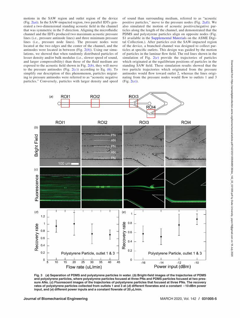
Fig. 3 (a) Separation of PDMS and polystyrene particles in water. (b) Bright-field images of the trajectories of PDMSand polystyrene particles, where polystyrene particles focused at three PNs and PDMS particles focused at two pres-sure ANs. (c) Fluorescent images of the trajectories of polystyrene particles that focused at three PNs. The recoveryrates of polystyrene particles collected from outlets 1 and 3 at (d) different flowrates and a constant 210 dBm powerinput, and (e) different power inputs and a constant flowrate of 20 lL/min.
Journal of Biomechanical Engineering MARCH 2020, Vol. 142 / 031005-5
Dow
nloaded from https://asm
edigitalcollection.asme.org/biom
echanical/article-pdf/142/3/031005/6489136/bio_142_03_031005.pdf by Duke U
niversity, yspro16@gm
ail.com on 18 July 2020
Separation of Polystyrene and PolydimethylsiloxaneParticles. Once we verified the mechanism of our acoustic sepa-ration device through simulations, we experimentally tested ourdevice’s ability to separate PDMS (polydisperse diameters,1–20 lm) and polystyrene particles (diameter 5 lm) in water (Fig.3). In this demonstration, the PDMS particles have a lower densityand higher compressibility than water, meaning that they shouldmove to the pressure antinodes; the relatively stiff polystyreneparticles should aggregate at the pressure nodes. From region ofinterest (ROI) 1 of Figs. 3(b) and 3(c), it can be seen that the mix-ture of particles was distributed randomly before the SAW-impacted region. When particles flowed through the SAW-impacted region, they were focused into five lines (ROI 2, Fig.3(b)). Fluorescent images confirmed that polystyrene particleswith green fluorescence focused at the three pressure node lines atthe sidewalls and the center of the channel, and the bright fieldimages confirmed that the PDMS particles aligned along the anti-node lines (ROI 2, Fig. 3(c)). The focused particles exited fromthe SAW-impacted regions to the outlets. The polystyrene par-ticles that were focused at the central line flow out at outlet 1(ROI 3, Fig. 3(b)); polystyrene particles focused at the two edgesof the channel were collected at outlet 3 (ROI 4, Fig. 3(c)). Thetwo lines of focused PDMS particles were collected at outlet 2(ROI 4, Fig. 3(b)).
The recovery rate of polystyrene particles collected from outlets1 and 3 was calculated according to Eq. (1) at different flowratesand power inputs. To test the effect of the flowrate, the recoveryrate of polystyrene particles from outlets 1 and 3 was evaluated atflowrates from 10, 20, 30, and 40 lL/min, and a constant�10 dBm of power input (Fig. 3(d)). At flowrates of 10 and20 lL/min, the average recovery rate of the polystyrene particleswas 95% and 99%, respectively, indicating that almost all of theparticles were collected from the expected outlets. When the flow-rate increased to 30 lL/min, the recovery rate began to decrease,falling to 73%; at the largest flowrate tested in the experiments(40 lL/min), the particle recovery rate dropped to 70%. When theflowrate increased, the time that the particles spent in the SAWregion was reduced, interrupting the particles’ migration to theirequilibrium positions and resulting in a lower recovery rate. Wealso explored how the power input influences the recovery rate ofpolystyrene particles (Fig. 3(e)). We found that at a constant flow-rate of 20 lL/min and lower power inputs (�16 and �14 dBm),
the recovery rate was also low because the weak acoustic radia-tion force was not sufficient to move particles to their equilibriumpositions. This was resolved when the power input was increasedto �12 and �10 dBm, where the particle recovery rate increasedto 90%.
The numerical and experimental exploration of PDMS andpolystyrene particle separation demonstrated several key featuresof our technique. First, this separation mechanism is based on thedifference in physical properties, rather than the size, of particles.Despite wide distributed size of PDMS particles (i.e., 1 to 20 lm),they all focused at pressure antinodes that were distinct from thepolystyrene particles’ equilibrium positions. However, althoughthe separation mechanism is independent of the size of the par-ticles, the authors would like to note that size still plays a factor inthe efficiency of this separation, and the device may not be able toseparate particles of any size. That is, particles that are too small(diameter less than 1 lm) are difficult to focus since the acousticradiation force is proportional to the volume of particles. Nonethe-less, with sufficient power and active IDT length, smaller particlescould eventually reach their equilibrium positions with this tech-nique. Second, this method does not require a sheath flow toestablish the initial positions of particles/cells; this means thatonly a single inlet is needed to inject the mixture of particles, sim-plifying the control of the system. Third, the throughput of separa-tion could potentially be improved by increasing the channelwidth and the flowrate. We designed a cell separation channelwith double the width (640 lm); in this design, the particles werefocused into nine lines (five lines for polystyrene particles andfour lines for PDMS particles), while other operation propertieswere unchanged (Fig. S2 available in the Supplemental Materialson the ASME Digital Collection.). The increased number of node/antinode lines in this device allows us to increase the total flow-rate while maintaining the channel flow velocity and deviceperformance.
Particle/Cell Separation by Adjusting Acoustic Propertiesof the Fluidic Medium. PDMS and polystyrene particles can beseparated in water due to their inherent differences in density andcompressibility. However, almost all cells (e.g., Hela cell andWBCs) have larger densities than water due to their cellular con-tent; this means that they all tend to move to pressure nodes in
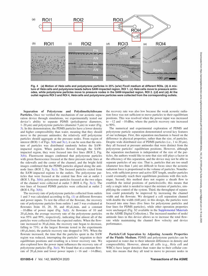
Fig. 4 (a) Motion of Hela cells and polystyrene particles in 25% (w/w) Ficoll medium at different ROIs. (b) A mix-ture of Hela cells and polystyrene beads before SAW-impacted region, ROI 1. (c) Hela cells move to pressure antin-odes, while polystyrene particles move to pressure nodes in the SAW-impacted region, ROI 2. ((d) and (e)) At theoutlet regions ROI 3 and ROI 4, Hela cells and polystyrene particles were collected from the corresponding outlets.
031005-6 / Vol. 142, MARCH 2020 Transactions of the ASME
Dow
nloaded from https://asm
edigitalcollection.asme.org/biom
echanical/article-pdf/142/3/031005/6489136/bio_142_03_031005.pdf by Duke U
niversity, yspro16@gm
ail.com on 18 July 2020

water or buffer solutions, preventing acoustic separations usingthis mechanism. To separate different types of cells using ourmethod, the acoustic properties of the fluidic medium need to bemanipulated so that one cell type will become acoustically nega-tive, while the other type of cell will remain acoustically positive.To achieve this manipulation, Ficoll was introduced into thesuspension medium. Ficoll is a high-molecular weight sucrose-polymer formed by copolymerization of sucrose with epichloro-hydrin [53–56]. The density of a Ficoll solution can beconveniently controlled by its concentration [57]. As such, by tun-ing the concentration of Ficoll, the equilibrium positions of cellscan be manipulated to pressure nodes or antinodes. Additionally,research has shown that the addition of Ficoll to cell suspensionsdoes not negatively affect the cell viability [57].
This exploitation was confirmed by analyzing the trajectories ofHela cells and polystyrene beads in 25% (w/w) Ficoll in PBSbuffer (Fig. 4(a)). In PBS, both Hela cells and polystyreneparticles would travel to pressure nodes. However, in the Ficollsolution, the Hela cells move to pressure antinodes (Fig. 4(c)) andare collected from outlet 2 (Fig. 4(e)). As expected, the polysty-rene particles still migrated to the pressure nodes at the center andtwo edges of channel (Fig. 4(c)), and could be collected from out-lets 1 and 3 (Fig. 4(d)). This phenomenon is consistent with thefact that although the density of polystyrene (1050 kg/m3) is
similar to that of Hela cells, the significantly greater speed ofsound in polystyrene (2350 m/s) than water means that polysty-rene particles remain acoustically positive. In addition, the Helacells are still able to attach and culture after separation, indicatingthat the Hela cells remained intact in the Ficoll medium and underthe influence of the SAWs.
Acoustic Cell Separation Based on Density. In this section,WBCs and RBCs were separated based on their differences indensity. The separation of WBCs and RBCs has been proven as avery important process in many biomedical applications such asthe proteomic or genomic analysis of WBCs [58], where bloodsamples need to be separated prior to analysis. However, usingacoustic-based methods to separate RBCs from WBCs is chal-lenging; although the volume of RBCs is less than WBCs, thelarger densities of RBCs neutralize this difference so that the radi-ation forces on WBCs and RBCs are very similar. As such, modi-fying the fluid properties using our device should enable moreefficient acoustic-based separation of RBCs and WBCs.
In the experiment, a spiked WBC and RBC sample was used tocontrol their ratio between the cell types in the test sample.Specifically, WBCs collected from 1 mL of whole blood were sus-pended in a 30% (w/w) Ficoll solution in PBS; whole blood wasadded to the mixture to yield a final RBC/WBC ratio of
Fig. 5 Acoustic separation of RBCs and WBCs. (a) Bright-field images of WBC and RBC mixtures show the cells focused atfive lines at positions of PNs and ANs. (b) Fluorescent image showing the trajectories of WBCs stained by Hoechst in the mix-ture, where WBCs are primarily focused at pressure ANs. (c) Plot of the recovery rate of RBCs and WBCs at three outlets.
Fig. 6 Acoustic separation of fresh and paraformaldehyde treated Hela cells. (a) Paraformaldehyde-treated Hela cells focusedinto three lines at the positions of PNs. (b) Fresh Hela cells focused into two lines at the positions of the pressure ANs. (c) Plotof the recovery rate of the two different cell groups at the three outlets.
Journal of Biomechanical Engineering MARCH 2020, Vol. 142 / 031005-7
Dow
nloaded from https://asm
edigitalcollection.asme.org/biom
echanical/article-pdf/142/3/031005/6489136/bio_142_03_031005.pdf by Duke U
niversity, yspro16@gm
ail.com on 18 July 2020
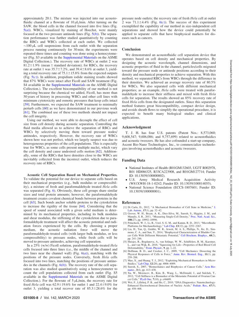
approximately 20:1. The mixture was injected into our acousto-fluidic channel at a flowrate of 10 lL/min. After turning on theSAW, the blood cells in the channel focused into five lines (Fig.5(a)). WBCs, visualized by staining of Hoechst, were mainlyfocused at the two pressure antinode lines (Fig. 5(b)). The separa-tion performance was further studied quantitatively by countingthe RBCs and WBCs collected at each outlet. We collected�100 lL cell suspensions from each outlet with the separationprocess running continuously for 30 min; the experiments wererepeated three times and counting was done using a hemocytome-ter (Fig. S3 available in the Supplemental Materials on the ASMEDigital Collection.). The recovery rate of WBCs at outlet 2 was81.261.9% (mean 6 standard deviation); for RBCs, the recoveryrate at outlet 1 was 35.767.2%, and 39.468.6% at outlet 3, yield-ing a total recovery rate of 75.1615.8% from the expected outputs(Fig. 5(c)). In addition, propidium iodide staining results showedthat 87% WBCs were intact after Ficoll and SAW treatment (Fig.S4 available in the Supplemental Materials on the ASME DigitalCollection.). The excellent biocompatibility of our method is notsurprising because the chemical we added, Ficoll, has more than50 years of history in processing WBCs and other cell lines withminimum cytotoxicity and osmotic pressures that keep cells intact[59]. Furthermore, we expected the SAW treatment to minimallyperturb cells [60] as we have demonstrated in our previous work[61]. The combined use of these two methods should not impactthe cell integrity.
Using our method, we were able to decouple the effect of cellsize from cell density during acoustic separation. Controlling thefluid media allowed us to achieve the separation of RBCs andWBCs by selectively moving them toward pressure nodes/antinodes, respectively. However, the recovery rate of WBCsshown here was not perfect, which we largely suspect was due toheterogeneous properties of the cell populations. This is especiallytrue for WBCs, as some cells present multiple nuclei, which varythe cell density and cause undesired cells motion [62]. Addition-ally, some of the RBCs that have densities close to the WBCs areinevitably collected from the incorrect outlet, which reduces therecovery rate of RBCs.
Acoustic Cell Separation Based on Mechanical Properties.To validate the potential for our device to separate cells based ontheir mechanical properties (e.g., bulk modulus or compressibil-ity), a mixture of fresh and paraformaldehyde treated Hela cellswas separated (Fig. 6). Obviously, these cell groups share similarsizes and total protein amounts; however, the paraformaldehydetreatment creates covalent chemical bonds between proteins in thecell [63]. Such bonds anchor soluble proteins to the cytoskeletonto increase the rigidity of the tissue [64]. Considering that thespeed of sound associated with a given solid medium is deter-mined by its mechanical properties, including its bulk modulusand shear modulus, the stiffening of the cytoskeleton due to para-formaldehyde treatment will affect the acoustic potential and radi-ation forces experienced by the cells. By choosing a propermedium, the acoustic radiation force will move theparaformaldehyde-treated cells (with larger bulk modulus, or lesscompressibility) to pressure nodes, while fresh cells will bemoved to pressure antinodes, achieving cell separation.
In a 25% (w/w) Ficoll solution, paraformaldehyde-treated Helacells focused into three lines (i.e., the middle of the channel andtwo lines near the channel wall) (Fig. 6(a)), matching with thepositions of the pressure nodes. Conversely, fresh Hela cellsfocused into two lines, matching the positions of pressure antino-des in the channels (Fig. 6(b)). The recovery rate of the cell sepa-ration was also studied quantitatively using a hemocytometer tocount the cell populations collected from each outlet (Fig. S5available in the Supplemental Materials on the ASME DigitalCollection.). For the flowrate of 5 lL/min, the recovery rate forfixed Hela cell was 62.9619.6% for outlet 1 and 22.469.0% foroutlet 3, yielding a total recover rate of 85.3628.6% for the
pressure node outlets; the recovery rate of fresh Hela cell at outlet2 was 71.164.4% (Fig. 6(c)). The success of this experimentexemplified the capability of our method in size-independent cellseparations and showed how the device could potentially beapplied to separate cells that have biophysical markers for dis-eases such as cancers.
Conclusion
We demonstrated an acoustofluidic cell separation device thatoperates based on cell density and mechanical properties. Bydesigning the acoustic wavelength, channel dimensions, andacoustic properties of fluid in the channel, particles/cells migratedtoward the pressure node or antinode positions according to theirdensity and mechanical properties to achieve separation. With thismethod, we separated RBCs from WBCs through the difference intheir densities. We achieved an average recovery rate of 80.5%for WBCs. We also separated cells with different mechanicalproperties; as an example, Hela cells were treated with parafor-maldehyde to increase their stiffness and mixed with fresh Helacells for separation. The results showed an 85% recovery rate offixed Hela cells from the designated outlets. Since this separationmethod features great biocompatibility, compact device design,and avoids sheath flows to simplify the operational procedure, it isexpected to benefit many biological studies and clinicalapplications.
Acknowledgment
T. J. H. has four U.S. patents (Patent Nos.: 8,573,060;9,608,547; 9,606,086; and 9,757,699) related to acoustofluidicsand acoustic tweezers. He has also cofounded a start-up company,Ascent Bio-Nano Technologies, Inc., to commercialize technolo-gies involving acoustofluidics and acoustic tweezers.
Funding Data
National Institutes of Health (R01GM132603, UG3T R002978,R01 HD086325, R33CA223908, and R01GM127714; FunderID: 10.13039/100000002).
U.S. Army Medical Research Acquisition Activity(W81XWH-18-1-0242; Funder ID: 10.13039/100014055).
National Science Foundation (ECCS-1807601; Funder ID:10.13039/100000001).
References[1] Di Carlo, D., 2012, “A Mechanical Biomarker of Cell State in Medicine,” J.
Lab. Autom., 17(1), pp. 32–42.[2] Grover, W. H., Bryan, A. K., Diez-Silva, M., Suresh, S., Higgins, J. M., and
Manalis, S. R., 2011, “Measuring Single-Cell Density,” Proc. Natl. Acad. Sci.,108(27), pp. 10992–10996.
[3] Polacheck, W. J., Li, R., Uzel, S. G. M., and Kamm, R. D., 2013, “MicrofluidicPlatforms for Mechanobiology,” Lab Chip, 13(12), pp. 2252–2267.
[4] Liu, H., Tan, Q., Geddie, W. R., Jewett, M. A. S., Phillips, N., Ke, D., Sim-mons, C. A., and Sun, Y., 2014, “Biophysical Characterization of Bladder Can-cer Cells With Different Metastatic Potential,” Cell Biochem. Biophys., 68(2),pp. 241–246.
[5] Huisjes, R., Bogdanova, A., van Solinge, W. W., Schiffelers, R. M., Kaestner,L., and van Wijk, R., 2018, “Squeezing for Life—Properties of Red Blood CellDeformability,” Front. Physiol., 9, pp. 1–22.
[6] Hoffman, B. D., and Crocker, J. C., 2009, “Cell Mechanics: Dissecting thePhysical Responses of Cells to Force,” Annu. Rev. Biomed. Eng., 11(1), pp.259–288.
[7] Mao, X., and Huang, T. J., 2012, “Exploiting Mechanical Biomarkers in Micro-fluidics,” Lab Chip, 12(20), pp. 4006–4009.
[8] Suresh, S., 2007, “Biomechanics and Biophysics of Cancer Cells,” Acta Bio-mater., 3(4), pp. 413–438.
[9] Xu, W., Mezencev, R., Kim, B., Wang, L., McDonald, J., and Sulchek, T.,2012, “Cell Stiffness is a Biomarker of the Metastatic Potential of Ovarian Can-cer Cells,” PLoS One, 7(10), p. e46609.
[10] Wei, F., Lillehoj, P. B., and Ho, C., 2010, “DNA Diagnostics: Nanotechnology-Enhanced Electrochemical Detection of Nucleic Acids,” Pediatr. Res., 67(5),pp. 458–468.
031005-8 / Vol. 142, MARCH 2020 Transactions of the ASME
Dow
nloaded from https://asm
edigitalcollection.asme.org/biom
echanical/article-pdf/142/3/031005/6489136/bio_142_03_031005.pdf by Duke U
niversity, yspro16@gm
ail.com on 18 July 2020

[11] Pisanic Ii, T. R., Zhang, Y., and Wang, T. H., 2014, “Quantum Dots in Diagnos-tics and Detection: Principles and Paradigms,” Analyst, 139(12), pp.2968–2981.
[12] Ndukaife, J. C., Mishra, A., Guler, U., Nnanna, A. G. A., Wereley, S. T., andBoltasseva, A., 2014, “Photothermal Heating Enabled by Plasmonic Nanostruc-tures for Electrokinetic Manipulation and Sorting of Particles,” ACS Nano,8(9), pp. 9035–9043.
[13] Guo, F., French, J. B., Li, P., Zhao, H., Chan, C. Y., Fick, J. R., Benkovic, S. J.,and Huang, T. J., 2013, “Probing Cell–Cell Communication With MicrofluidicDevices,” Lab Chip, 13(16), pp. 3152–3162.
[14] Tsutsui, H., and Ho, C.-M., 2009, “Cell Separation by Non-Inertial Force Fieldsin Microfluidic Systems,” Mech. Res. Commun., 36(1), pp. 92–103.
[15] English, D., and Andersen, B. R., 1974, “Single-Step Separation of Red BloodCells, Granulocytes and Mononuclear Leukocytes on Discontinuous DensityGradients of Ficoll-Hypaque,” J. Immunol. Methods, 5(3), pp. 249–252.
[16] Bow, H., Pivkin, I. V., Diez-Silva, M., Goldfless, S. J., Dao, M., Niles, J. C.,Suresh, S., and Han, J., 2011, “A Microfabricated Deformability-Based FlowCytometer With Application to Malaria,” Lab Chip, 11(6), pp. 1065–1073.
[17] Zhang, Z., Xu, J., Hong, B., and Chen, X., 2014, “The Effects of 3D ChannelGeometry on CTC Passing Pressure-Towards Deformability-Based Cancer CellSeparation,” Lab Chip, 14(14), pp. 2576–2584.
[18] Wang, G., Mao, W., Byler, R., Patel, K., Henegar, C., Alexeev, A., and Sul-chek, T., 2013, “Stiffness Dependent Separation of Cells in a MicrofluidicDevice,” PLoS One, 8(10), p. e75901.
[19] Van Den Bergh, J. P. W., Van Lenthe, G. H., Hermus, A. R. M. M., Corstens,F. H. M., Smals, A. G. H., and Huiskes, R., 2000, “Speed of Sound ReflectsYoung’s Modulus as Assessed by Microstructural Finite Element Analysis,”Bone, 26(5), pp. 519–524.
[20] Wang, G., Crawford, K., Turbyfield, C., Lam, W., Alexeev, A., and Sulchek,T., 2015, “Microfluidic Cellular Enrichment and Separation Through Differen-ces in Viscoelastic Deformation,” Lab Chip, 15(2), pp. 532–540.
[21] Lin, B. K., McFaul, S. M., Jin, C., Black, P. C., and Ma, H., 2013, “HighlySelective Biomechanical Separation of Cancer Cells From Leukocytes UsingMicrofluidic Ratchets and Hydrodynamic Concentrator,” Biomicrofluidics,7(3), p. 034114.
[22] Hur, S. C., Henderson-MacLennan, N. K., McCabe, E. R. B., and Di Carlo, D.,2011, “Deformability-Based Cell Classification and Enrichment Using InertialMicrofluidics,” Lab Chip, 11(5), pp. 912–920.
[23] Yang, S., Lee, S. S., Ahn, S. W., Kang, K., Shim, W., Lee, G., Hyun, K., andKim, J. M., 2012, “Deformability-Selective Particle Entrainment and Separa-tion in a Rectangular Microchannel Using Medium Viscoelasticity,” Soft Mat-ter, 8(18), pp. 5011–5019.
[24] Holmes, D., Whyte, G., Bailey, J., Vergara-Irigaray, N., Ekpenyong, A., Guck,J., and Duke, T., 2014, “Separation of Blood Cells With Differing DeformabilityUsing Deterministic Lateral Displacement,” Interface Focus, 4(6), p. 20140011.
[25] Hvichia, G. E., Parveen, Z., Wagner, C., Janning, M., Quidde, J., Stein, A.,M€uller, V., Loges, S., Neves, R. P. L., Stoecklein, N. H., Wikman, H., Rieth-dorf, S., Pantel, K., and Gorges, T. M., 2016, “A Novel Microfluidic Platformfor Size and Deformability Based Separation and the Subsequent MolecularCharacterization of Viable Circulating Tumor Cells,” Int. J. Cancer, 138(12),pp. 2894–2904.
[26] Yeo, L. Y., and Friend, J. R., 2014, “Surface Acoustic Wave Microfluidics,”Annu. Rev. Fluid Mech., 46(1), pp. 379–406.
[27] Tian, Z., Yang, S., Huang, P.-H., Wang, Z., Zhang, P., Gu, Y., Bachman, H.,Chen, C., Wu, M., Xie, Y., and Huang, T. J., 2019, “Wave Number–SpiralAcoustic Tweezers for Dynamic and Reconfigurable Manipulation of Particlesand Cells,” Sci. Adv., 5(5), p. eaau6062.
[28] Zhang, S. P., Lata, J., Chen, C., Mai, J., Guo, F., Tian, Z., Ren, L., Mao, Z., Huang,P.-H., Li, P., Yang, S., and Huang, T. J., 2018, “Digital Acoustofluidics EnablesContactless and Programmable Liquid Handling,” Nat. Commun., 9(1), p. 2928.
[29] Li, P., and Huang, T. J., 2019, “Applications of Acoustofluidics in BioanalyticalChemistry,” Anal. Chem., 91(1), pp. 757–767.
[30] Xie, Y., Bachman, H., and Huang, T. J., 2019, “Acoustofluidic Methods in CellAnalysis,” TrAC Trends Anal. Chem., 117, pp. 280–290.
[31] Wu, M., Ozcelik, A., Rufo, J., Wang, Z., Fang, R., and Jun Huang, T., 2019,“Acoustofluidic Separation of Cells and Particles,” Microsystems Nanoeng.,5(1), p. 32.
[32] Wu, M., Huang, P.-H., Zhang, R., Mao, Z., Chen, C., Kemeny, G., Li, P., Lee,A. V., Gyanchandani, R., Armstrong, A. J., Dao, M., Suresh, S., and Huang, T.J., 2018, “Circulating Tumor Cell Phenotyping Via High-Throughput AcousticSeparation,” Small, 14(32), p. 1801131.
[33] Ozcelik, A., Rufo, J., Guo, F., Gu, Y., Li, P., Lata, J., and Huang, T. J., 2018,“Acoustic Tweezers for the Life Sciences,” Nat. Methods, 15(12), pp.1021–1028.
[34] Wu, M., Ouyang, Y., Wang, Z., Zhang, R., Huang, P.-H., Chen, C., Li, H., Li,P., Quinn, D., Dao, M., Suresh, S., Sadovsky, Y., and Huang, T. J., 2017,“Isolation of Exosomes From Whole Blood by Integrating Acoustics andMicrofluidics,” Proc. Natl. Acad. Sci., 114(40), pp. 10584–10589.
[35] Augustsson, P., Magnusson, C., Nordin, M., Lilja, H., and Laurell, T., 2012,“Microfluidic, Label-Free Enrichment of Prostate Cancer Cells in Blood Basedon Acoustophoresis,” Anal. Chem., 84(18), pp. 7954–7962.
[36] Antfolk, M., Magnusson, C., Augustsson, P., Lilja, H., and Laurell, T., 2015,“Acoustofluidic, Label-Free Separation and Simultaneous Concentration ofRare Tumor Cells From White Blood Cells,” Anal. Chem., 87(18), pp.9322–9328.
[37] Franke, T., Braunm€uller, S., Schmid, L., Wixforth, A., and Weitz, D. A., 2010,“Surface Acoustic Wave Actuated Cell Sorting (SAWACS),” Lab Chip, 10(6),pp. 789–794.
[38] Bourquin, Y., Syed, A., Reboud, J., Ranford-Cartwright, L. C., Barrett, M. P.,and Cooper, J. M., 2014, “Rare-Cell Enrichment by a Rapid, Label-Free, Ultra-sonic Isopycnic Technique for Medical Diagnostics,” Angew. Chem. Int. Ed.,53(22), pp. 5587–5590.
[39] Collins, D. J., Alan, T., and Neild, A., 2014, “Particle Separation Using VirtualDeterministic Lateral Displacement (VDLD),” Lab Chip, 14(9), pp. 1595–1603.
[40] Destgeer, G., Lee, K. H., Jung, J. H., Alazzam, A., and Sung, H. J., 2013,“Continuous Separation of Particles in a PDMS Microfluidic Channel Via Trav-elling Surface Acoustic Waves (TSAW),” Lab Chip, 13(21), pp. 4210–4216.
[41] Ma, Z., Collins, D. J., and Ai, Y., 2016, “Detachable Acoustofluidic System forParticle Separation Via a Traveling Surface Acoustic Wave,” Anal. Chem.,88(10), pp. 5316–5323.
[42] Yunus, D. E., Sohrabi, S., He, R., Shi, W., and Liu, Y., 2017, “Acoustic Pattern-ing for 3D Embedded Electrically Conductive Wire in Stereolithography,” J.Micromech. Microeng., 27(4), p. 045016.
[43] Shi, J., Ahmed, D., Mao, X., Lin, S.-C. S., Lawit, A., and Huang, T. J., 2009,“Acoustic Tweezers: Patterning Cells and Microparticles Using Standing Sur-face Acoustic Waves (SSAW),” Lab Chip, 9(20), pp. 2890–2895.
[44] Ding, X., Peng, Z., Lin, S.-C. S., Geri, M., Li, S., Li, P., Chen, Y., Dao, M.,Suresh, S., and Huang, T. J., 2014, “Cell Separation Using Tilted-Angle Stand-ing Surface Acoustic Waves,” Proc. Natl. Acad. Sci., 111(36), pp.12992–12997.
[45] Lei, J., Hill, M., de Le�on Albarr�an, C. P., and Glynne-Jones, P., 2018, “Effectsof Micron Scale Surface Profiles on Acoustic Streaming,” Microfluid. Nano-fluid., 22(12), p. 140.
[46] Lei, J., Glynne-Jones, P., and Hill, M., 2016, “Modal Rayleigh-Like Streamingin Layered Acoustofluidic Devices,” Phys. Fluids, 28(1), p. 012004.
[47] Bernassau, A. L., Chun-Kiat, Ong, Yong, Ma, Macpherson, P. G. A., Courtney,C. R. P., Riehle, M., Drinkwater, B. W., and Cumming, D. R. S., 2011, “Two-Dimensional Manipulation of Micro Particles by Acoustic Radiation Pressurein a Heptagon Cell,” IEEE Trans. Ultrason. Ferroelectr. Freq. Control, 58(10),pp. 2132–2138.
[48] Melde, K., Choi, E., Wu, Z., Palagi, S., Qiu, T., and Fischer, P., 2018,“Acoustic Fabrication Via the Assembly and Fusion of Particles,” Adv. Mater.,30(3), p. 1704507.
[49] Wu, M., Chen, K., Yang, S., Wang, Z., Huang, P. H., Mai, J., Li, Z., and Huang,T. J., 2018, “High-Throughput Cell Focusing and Separation via AcoustofluidicTweezers,” Lab Chip, 18, pp. 3003–3010.
[50] Aghaamoo, M., Zhang, Z., Chen, X., and Xu, J., 2015, “Deformability-BasedCirculating Tumor Cell Separation With Conical-Shaped Microfilters: Concept,Optimization, and Design Criteria,” Biomicrofluidics, 9(3), p. 034106.
[51] Bruus, H., 2012, “Acoustofluidics 2: Perturbation Theory and Ultrasound Reso-nance Modes,” Lab Chip, 12(1), pp. 20–28.
[52] Gorkov, L. P., 1962, “On the Forces Acting on a Small Particle in an AcousticalField in an Ideal Fluid,” Sov. Phys.-Dokl., 6, pp. 773–775.
[53] Georgalis, Y., Philipp, M., Aleksandrova, R., and Kr€uger, J. K., 2012, “LightScattering Studies on Ficoll PM70 Solutions Reveal Two Distinct DiffusiveModes,” J. Colloid Interface Sci., 386(1), pp. 141–147.
[54] Chen, B., Wang, B., Zhang, W. J., Zhou, G., Cao, Y., and Liu, W., 2013,“Macromolecular Crowding Effect on Cartilaginous Matrix Production: AComparison of Two-Dimensional and Three-Dimensional Models,” TissueEng., Part C, 19(8), pp. 586–595.
[55] Rashid, R., Raghunath, M., and Wohland, T., 2011, “Macromolecular Crowd-ing and Stem Cell Differentiation,” Biophys. J., 100(3), pp. 142a–143a.
[56] Zeiger, A. S., Loe, F. C., Li, R., Raghunath, M., and Van Vliet, K. J., 2012,“Macromolecular Crowding Directs Extracellular Matrix Organization andMesenchymal Stem Cell Behavior,” PLoS One, 7(5), p. e37904.
[57] Pretlow, T. G., Boone, C. W., Shrager, R. I., and Weiss, G. H., 1969, “RateZonal Centrifugation in a Ficoll Gradient,” Anal. Biochem., 29(2), pp.230–237.
[58] Boyum, A., 1964, “Separation of White Blood Cells,” Nature, 204(4960), pp.793–794.
[59] Ulla, K., and Hallberg, T., 1983, “Separation of Lymphocyte Subsets byExpanding Velocity Sedimentation of E-Rosettes at Unit Gravity,” J. Immunol.Methods, 59, pp. 349–360.
[60] Wiklund, M., 2012, “Acoustofluidics 12: Biocompatibility and Cell Viability inMicrofluidic Acoustic Resonators,” Lab Chip, 12(11), pp. 2018–2028.
[61] Ding, X., Lin, S.-C. S., Kiraly, B., Yue, H., Li, S., Chiang, I.-K., Shi, J., Ben-kovic, S. J., and Huang, T. J., 2012, “On-Chip Manipulation of Single Micro-particles, Cells, and Organisms Using Surface Acoustic Waves,” Proc. Natl.Acad. Sci., 109(28), pp. 11105–11109.
[62] Kounis, N. G., Soufras, G. D., Tsigkas, G., and Hahalis, G., 2015, “White BloodCell Counts, Leukocyte Ratios, and Eosinophils as Inflammatory Markers inPatients With Coronary Artery Disease,” Clin. Appl. Thromb., 21(2), pp.139–143.
[63] Thavarajah, R., Mudimbaimannar, V., Rao, U., Ranganathan, K., and Elizabeth,J., 2012, “Chemical and Physical Basics of Routine Formaldehyde Fixation,” J.Oral Maxillofac. Pathol., 16(3), pp. 400–405.
[64] Kim, S.-O., Kim, J., Okajima, T., and Cho, N.-J., 2017, “Mechanical Propertiesof Paraformaldehyde-Treated Individual Cells Investigated by Atomic ForceMicroscopy and Scanning Ion Conductance Microscopy,” Nano Converg., 4(1),p. 5.
Journal of Biomechanical Engineering MARCH 2020, Vol. 142 / 031005-9
Dow
nloaded from https://asm
edigitalcollection.asme.org/biom
echanical/article-pdf/142/3/031005/6489136/bio_142_03_031005.pdf by Duke U
niversity, yspro16@gm
ail.com on 18 July 2020