ACO Building Drainage...ACO Building Drainage ACO offers drainage systems designed to protect your...
52
STAINLESS STEEL TRENCH BROCHURE Modular 125 Modular 200 Slot Drain 20 Custom Solutions ACO Building Drainage
Transcript of ACO Building Drainage...ACO Building Drainage ACO offers drainage systems designed to protect your...

STAINLESS STEEL TRENCH BROCHURE Modular 125
Modular 200
Slot Drain 20
Custom Solutions
ACO Building Drainage
www.acousa.com2
ACO Building Drainage
ACO offers drainage systems designed
to protect your business and the
environment. The stainless steel floor
drainage products in the Building
Drainage product line are designed for
ultimate hygienic and corrosion resistant
performance, ensuring health & safety of
workers, customers and products while
still allowing clean-in-place functionality.
www.acousa.com
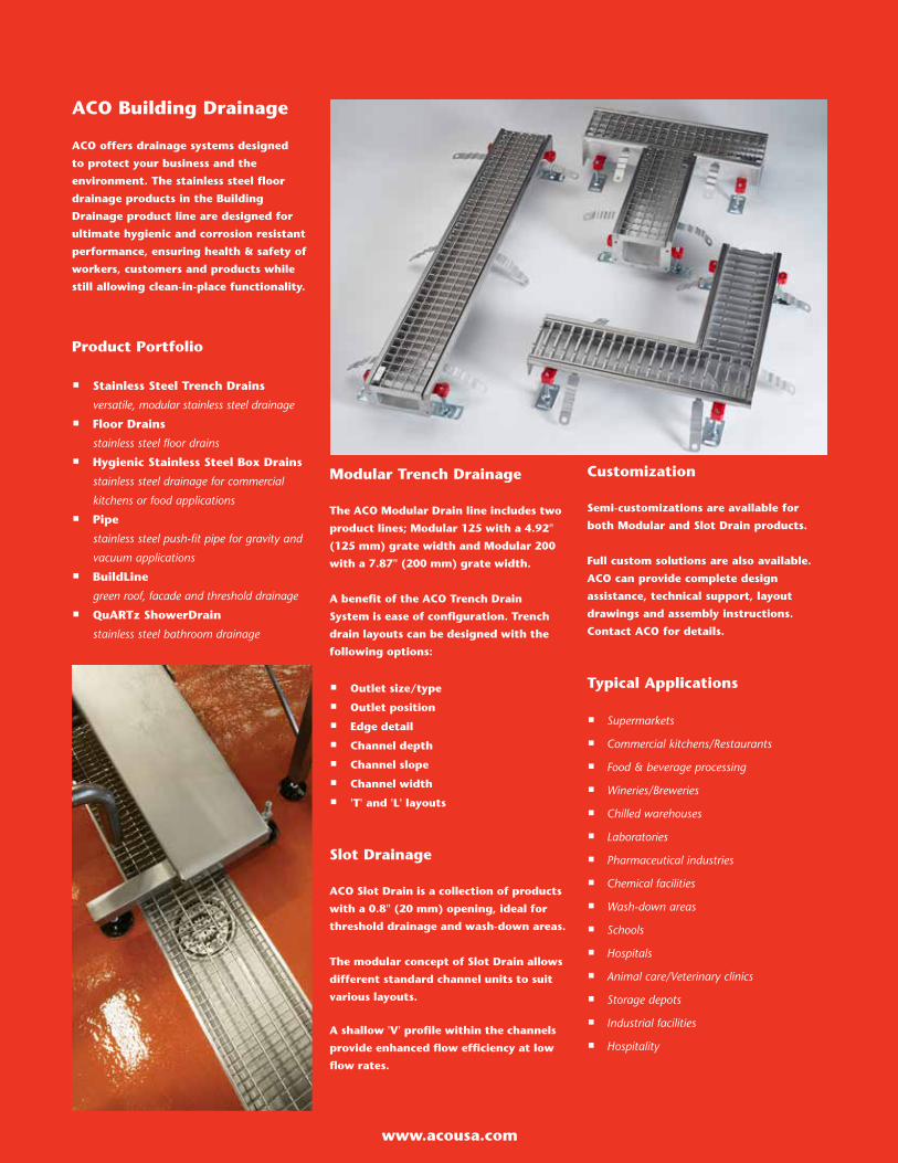
Modular Trench Drainage
The ACO Modular Drain line includes two
product lines; Modular 125 with a 4.92"
(125 mm) grate width and Modular 200
with a 7.87" (200 mm) grate width.
A benefit of the ACO Trench Drain
System is ease of configuration. Trench
drain layouts can be designed with the
following options:
� Outlet size/type
� Outlet position
� Edge detail
� Channel depth
� Channel slope
� Channel width
� 'T' and 'L' layouts
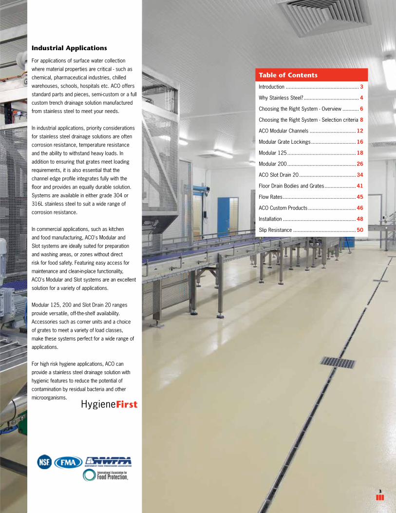
Slot Drainage
ACO Slot Drain is a collection of products
with a 0.8" (20 mm) opening, ideal for
threshold drainage and wash-down areas.
The modular concept of Slot Drain allows
different standard channel units to suit
various layouts.
A shallow 'V' profile within the channels
provide enhanced flow efficiency at low
flow rates.
Customization
Semi-customizations are available for
both Modular and Slot Drain products.
Full custom solutions are also available.
ACO can provide complete design
assistance, technical support, layout
drawings and assembly instructions.
Contact ACO for details.
Typical Applications
� Supermarkets
� Commercial kitchens/Restaurants
� Food & beverage processing
� Wineries/Breweries
� Chilled warehouses
� Laboratories
� Pharmaceutical industries
� Chemical facilities
� Wash-down areas
� Schools
� Hospitals
� Animal care/Veterinary clinics
� Storage depots
� Industrial facilities
� Hospitality
Product Portfolio
� Stainless Steel Trench Drains
versatile, modular stainless steel drainage
� Floor Drains
stainless steel floor drains
� Hygienic Stainless Steel Box Drains
stainless steel drainage for commercial
kitchens or food applications
� Pipe
stainless steel push-fit pipe for gravity and
vacuum applications
� BuildLine
green roof, facade and threshold drainage
� QuARTz ShowerDrain
stainless steel bathroom drainage
3
ACO STAINLESS TRENCH
www.acousa.com
Introduction ................................................. 3
Why Stainless Steel? ..................................... 4
Choosing the Right System - Overview ........... 6
Choosing the Right System - Selection criteria 8
ACO Modular Channels ............................... 12
Modular Grate Lockings .............................. 16
Modular 125 .............................................. 18
Modular 200 .............................................. 26
ACO Slot Drain 20 ...................................... 34
Floor Drain Bodies and Grates ..................... 41
Flow Rates ................................................. 45
ACO Custom Products ................................ 46
Installation ................................................. 48
Slip Resistance .......................................... 50
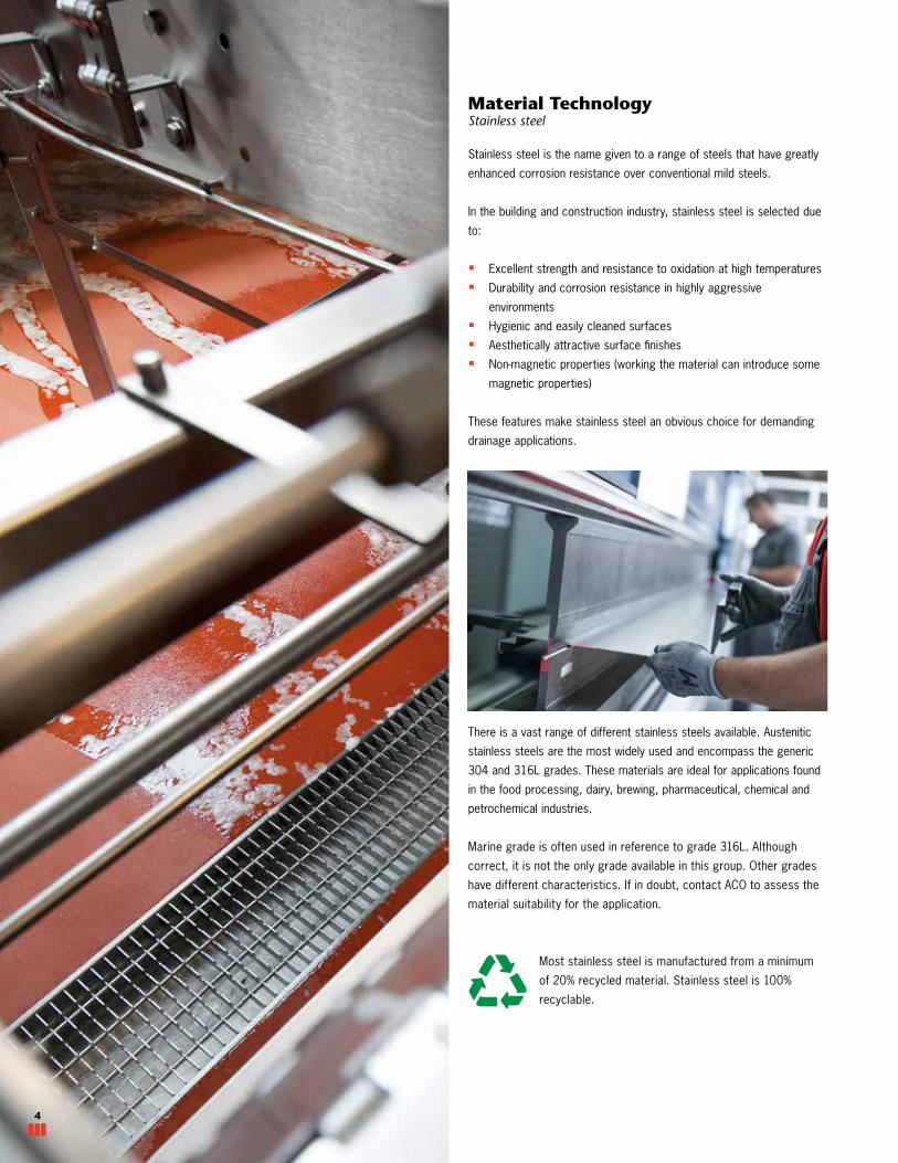
Industrial Applications
For applications of surface water collection
where material properties are critical - such as
chemical, pharmaceutical industries, chilled
warehouses, schools, hospitals etc. ACO offers
standard parts and pieces, semi-custom or a full
custom trench drainage solution manufactured
from stainless steel to meet your needs.
In industrial applications, priority considerations
for stainless steel drainage solutions are often
corrosion resistance, temperature resistance
and the ability to withstand heavy loads. In
addition to ensuring that grates meet loading
requirements, it is also essential that the
channel edge profile integrates fully with the
floor and provides an equally durable solution.
Systems are available in either grade 304 or
316L stainless steel to suit a wide range of
corrosion resistance.
In commercial applications, such as kitchen
and food manufacturing, ACO's Modular and
Slot systems are ideally suited for preparation
and washing areas, or zones without direct
risk for food safety. Featuring easy access for
maintenance and clean-in-place functionality,
ACO's Modular and Slot systems are an excellent
solution for a variety of applications.
Modular 125, 200 and Slot Drain 20 ranges
provide versatile, off-the-shelf availability.
Accessories such as corner units and a choice
of grates to meet a variety of load classes,
make these systems perfect for a wide range of
applications.
For high risk hygiene applications, ACO can
provide a stainless steel drainage solution with
hygienic features to reduce the potential of
contamination by residual bacteria and other
microorganisms.
3
Table of Contents
Material Technology Stainless steel
Stainless steel is the name given to a range of steels that have greatly
enhanced corrosion resistance over conventional mild steels.
In the building and construction industry, stainless steel is selected due
to:
� Excellent strength and resistance to oxidation at high temperatures
� Durability and corrosion resistance in highly aggressive
environments
� Hygienic and easily cleaned surfaces
� Aesthetically attractive surface finishes
� Non-magnetic properties (working the material can introduce some
magnetic properties)
These features make stainless steel an obvious choice for demanding
drainage applications.
There is a vast range of different stainless steels available. Austenitic
stainless steels are the most widely used and encompass the generic
304 and 316L grades. These materials are ideal for applications found
in the food processing, dairy, brewing, pharmaceutical, chemical and
petrochemical industries.
Marine grade is often used in reference to grade 316L. Although
correct, it is not the only grade available in this group. Other grades
have different characteristics. If in doubt, contact ACO to assess the
material suitability for the application.
Most stainless steel is manufactured from a minimum
of 20% recycled material. Stainless steel is 100%
recyclable.
4
5
ACO STAINLESS TRENCH
www.acousa.com
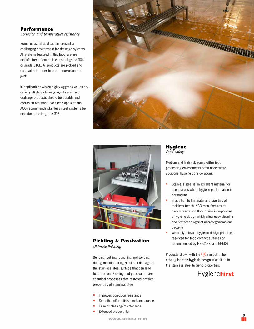
PerformanceCorrosion and temperature resistance
Some industrial applications present a
challenging environment for drainage systems.
All systems featured in this brochure are
manufactured from stainless steel grade 304
or grade 316L. All products are pickled and
passivated in order to ensure corrosion free
joints.
In applications where highly aggressive liquids,
or very alkaline cleaning agents are used
drainage products should be durable and
corrosion resistant. For these applications,
ACO recommends stainless steel systems be
manufactured in grade 316L.
Pickling & Passivation Ultimate finishing
Bending, cutting, punching and welding
during manufacturing results in damage of
the stainless steel surface that can lead
to corrosion. Pickling and passivation are
chemical processes that restores physical
properties of stainless steel.
� Improves corrosion resistance
� Smooth, uniform finish and appearance
� Ease of cleaning/maintenance
� Extended product life
HygieneFood safety
Medium and high risk zones within food
processing environments often necessitate
additional hygiene considerations.
� Stainless steel is an excellent material for
use in areas where hygiene performance is
paramount
� In addition to the material properties of
stainless trench, ACO manufactures its
trench drains and floor drains incorporating
a hygienic design which allow easy cleaning
and protection against microorganisms and
bacteria
� We apply relevant hygienic design principles
reserved for food contact surfaces or
recommended by NSF/ANSI and EHEDG
Products shown with the symbol in the
catalog indicate hygienic design in addition to
the stainless steel hygienic properties.

www.acousa.com6
Paving
Tile floor
External Applications
Internal Applications
1 LOADING - Grate Type & Edge Details
Choosing the Right System - Selection Overview
Consider type of traffic - pedestrian, carts,
forklifts. For wheeled traffic calculate wheel
load and contact area to estimate required psi
load (pneumatic tires have larger contact area
than solid tires).
Affects grate load class, channel edge detail
and installation details.
When selecting a stainless trench system,
careful consideration should be given to the
following factors:
3 SITE - Layout Requirements
Consider any fixed equipment and outlets to
work around, any restrictions to construction
depth, and type of flooring finish. BIM models
are available for standard products.
Affects product choice - fully standard parts
(often lower costs and lead time), semi
customized (shortened channels, non-standard
outlet size/position etc), or a full custom
solution. Flooring type may affect edge detail.
2 SITE - Material Requirements
Consider any chemical(s), concentration,
contact times, frequency and temperature.
Cleaning agents must also be considered.
Affects grade of stainless steel chosen (Grade
304 or 316L) and type of post fabrication
material finishing - pickling, passivation and
electropolishing. See page 10
7
ACO STAINLESS TRENCH
www.acousa.com
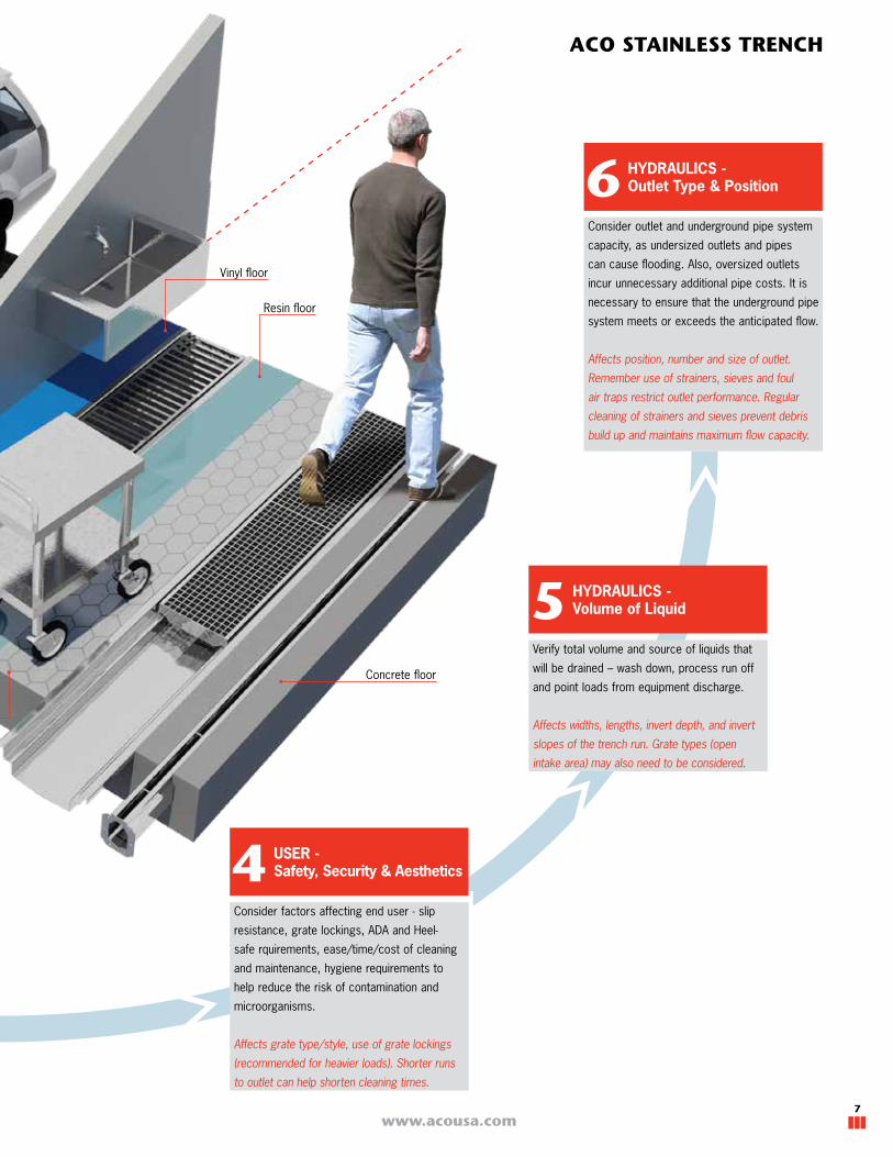
Vinyl floor
Resin floor
Concrete floor
HYDRAULICS - Outlet Type & Position6
Consider outlet and underground pipe system
capacity, as undersized outlets and pipes
can cause flooding. Also, oversized outlets
incur unnecessary additional pipe costs. It is
necessary to ensure that the underground pipe
system meets or exceeds the anticipated flow.
Affects position, number and size of outlet.
Remember use of strainers, sieves and foul
air traps restrict outlet performance. Regular
cleaning of strainers and sieves prevent debris
build up and maintains maximum flow capacity.
USER - Safety, Security & Aesthetics4
Consider factors affecting end user - slip
resistance, grate lockings, ADA and Heel-
safe rquirements, ease/time/cost of cleaning
and maintenance, hygiene requirements to
help reduce the risk of contamination and
microorganisms.
Affects grate type/style, use of grate lockings
(recommended for heavier loads). Shorter runs
to outlet can help shorten cleaning times.
HYDRAULICS - Volume of Liquid5
Verify total volume and source of liquids that
will be drained – wash down, process run off
and point loads from equipment discharge.
Affects widths, lengths, invert depth, and invert
slopes of the trench run. Grate types (open
intake area) may also need to be considered.

www.acousa.com8
1 LOADING - Grate Type & Edge Details
Choosing the Right System - Selection Details
ASME: A112.6.3 - 2016 Plumbing standard relating to internal floor drains.
Safe Live Load
EN 1433Load class of
similar rating:
EN 1253Load class of similar
rating:
4<8" channel
8<12" channel
All channel widths
Light Duty Less than 2,000lb
Medium Duty Between 2,000lb and 4,999lb
Heavy Duty Between 5,000lb and 7,499lb
Extra Heavy Duty Between 7,500lb and 9,999lb
Special Duty Greater than 10,000lb
A - B
B - C
C - D
D - E
E - F
A - B
B - D
D
E
E - F
L 15 - R 50
R 50 - M 125
M 125 - N 250
P400
-
In the US the ASME: A112.6.3 - 2016 is the most relevant standard. However, it is designed
primarily for floor drains and does not effectively address linear trench drains. ACO has
independent certification for floor drains to ASME 112.6.3 and EN 1253, trench drains are tested
to EN 1433 : 2002 Drainage channels for vehicular and pedestrian areas.
To assist with evaluating and comparing these standards to ACO products, a guide is provided
below equating stresses (psi) from ASME : A112.6.3 - 2016 Load categories to the Load Class
A - F categories from EN 1433. It is also broken down by internal channel widths. A comparison to
EN 1253 : 2015 Gullies for Buildings is also provided. Load class certification for each product is
available upon request.
Relevant Load StandardsLoading refers to any kind of traffic or load
being applied to the trench and grate.
To estimate load resistance required, consider:
� Type of traffic - Pedestrians, carts, forklift,
other vehicles, etc.
� Wheel loads - Include vehicle, weight of load
being carried and type of tire (solid wheel
vs. pneumatic tires create different size
contact area giving different psi loads).
� 'Unusual' traffic – e.g. food carts being
moved across trench etc.
� Frequency - Occasional versus frequent use
may also affect product choice.
� Dynamic loads
Load standards create a way to compare and
categorize loads - typically into several load
classes (light, medium and heavy etc.).
Load standards do not account for dynamic
(moving) loads. Faster moving and/or turning
loads will require a heavier duty drain and
grate. Applications with heavy duty turning
and/or braking traffic should avoid grates with
high anti-slip ratings as the dynamic nature will
potentially distort and damage those grates.
Pneumatic
tire
Same load transfered through pneumatic tire vs.
hard-wheel, heavy forklifts creates very different load
stress (psi).
Solid
wheel

9
ACO STAINLESS TRENCH
www.acousa.com
All ACO Stainless Steel Trench Systems are available with different edge details to suit varying load
requirements and the surrounding floor material.
Standard Edge
Suitable for tiled, concrete and epoxy resin floors in pedestrian and light industrial applications. Drains
without infill are susceptible to failure as the surrounding concrete rarely fills that void. As edges
compress, cavities create breeding grounds for pathogens and are impossible to clean. Edge in-fill in
other materials - contact ACO for details.
Solid Steel Edge In-fill - heavy duty
ACO recommends the use of a solid steel edge
in-fill when using class E grates or where fork
lift traffic is expected.
Stainless steel tack
welded into channel
edge
Hard rubber in-fill
pressed into
channel edge
Floor Angle Edge - heavy duty resin floor
Suitable for heavy duty tiled, paver and resin
floor applications, isolates channel from floor and
provides gap for sealant. If deeper steel angle
required contact ACO.
Vinyl Seal Edge - vinyl sheet floors
Fits standard channels - replaces standard edge
insert and provides an anchoring point and seal
between vinyl sheet flooring and trench edges.
(Vinyl Seal # 49061, flexible seal # 49062 per
meter)
Plastic insert to
provide anchor and
seal for sheet floors
Stainless steel
angle with 0.40"
(10 mm) spacer for
sealant
Extended Edge - tile floors
Suitable for tiled floors in pedestrian and light
industrial applications.
Extended channel
edge - height/
length to suit
Channel Edge Options
Loading will impact installation. It is necessary
that the installation detail and concrete
encasement provide sufficient support for all
anticipated loads.
Poor site conditions and low load bearing
pavements will require an increase in these
dimensions to meet both vertical and lateral
loads. Some applications will also require
concrete reinforcement.
Always seek engineering advice for specific
applications.
Installation Details
Semi-customization - Alternative Edge Options
Flexible seal
See page 42 for typical custom edge details
6
3.82in
6.02in VARIES
153mm
97mm
4" OR 6" PIPECONNECTION
4
53
8
1
7
2
4211 Pleasant Rd.
Casa Grande, AZ 85122
Fort Mill, SC 29708
BUILDING DRAINAGE MODULAR 125 - OUTLET
DRW NO:
STRAIGHT COUPLING (BY ACO)
7. ADJUSTABLE LOCATION FLANGE FLOOR DRAIN (BY ACO)
6.
Fax: 440-639-7235
Tel: 440-639-7230
ACO Polymer Products, Inc.
INSTALLATION DRAWING - ACO BUILDING DRAINAGE
DATE: 10/16RESIN FLOOR
Tel: 440-639-7230
Mentor, OH 44060
Fax: 803-802-1063
9470 Pinecone Dr.
Fax: 520-421-9899
Tel: 520-421-9988
4.
ENGINEERING ADVICE MAY BE REQUIRED.
MODULAR 125 OUTLET CHANNEL
5.CHOICE OF GRATE8.
THESE DETAILS ARE PROVIDED FOR REFERENCE ONLY. ACO RECOMMENDS CHECKING LOCAL STANDARDS AND PRACTICES.
9.
SPECIFICATION CLAUSE
825 W. Beechcraft St
NOTES:RESIN FLOOR
1.FLEXIBLE SEALANT
2.FLOOR SCREED
3.GROUND SLAB
ACO MODULAR 125 COMPLETE WITH * GRATE. OVERALL HEIGHT VARIES. MADE FROM 16ga (1.5mm) AISI 304 OR AISI 316L,
PICKLE PASSIVATED FINISH. ALL CHANNELS PROVIDED WITH NBR SEALS AND CONNECTION BOLTS ON ONE SIDE.
SYSTEM SHALL WITHSTAND LOADING TO LOAD CLASS AS OUTLINED BY EN 1433 / EN 1253. GRATE TYPE SHALL BE
APPROPRIATE TO MEET THE SYSTEM LOAD CLASS SPECIFIED AND INTENDED APPLICATION. THE SYSTEM SHALL BE
INSTALLED IN ACCORDANCE WITH THE MANUFACTURER'S INSTRUCTIONS AND RECOMMENDATIONS.
THE COMPLETE DRAINAGE SYSTEM SHALL BE SUPPLIED BY ACO POLYMER PRODUCTS, INC. ANY DEVIATION OR PARTIAL
SYSTEM DESIGN AND/OR IMPROPER INSTALLATION WILL VOID ANY AND ALL WARRANTIES PROVIDED BY ACO POLYMER
PRODUCTS, INC. CHANNEL SHALL WITHSTAND LOADING TO PROPER LOAD CLASS AS OUTLINED BY EN 1433. GRATE
TYPE SHALL BE APPROPRIATE TO MEET THE SYSTEM LOAD CLASS SPECIFIED AND INTENDED APPLICATION. THE
SYSTEM SHALL BE INSTALLED IN ACCORDANCE WITH THE MANUFACTURER'S INSTRUCTIONS AND RECOMMENDATIONS.
INSTALLERS MUST CHECK LOCAL PLUMBING CODES AND SEEK PROFESSIONAL ADVICE PRIOR TO INSTALLATION.
*INSERT GRATE TYPE
www.acousa.com10
Stainless steel is offered in several grades, ACO
offer trench drains and grates in non-magnetic
Austenitic stainless steel (see note page 4) in
either Grade 304 or 316L. All products are
pickled and passivated, and grates can be
electropolished.
Typical factors that affect material selection:
� Types of chemicals
� Concentration percentages
� Contact time with trench system
� Temperatures of liquid flowing into trench
� Flushing system used
� Type of cleaning agent
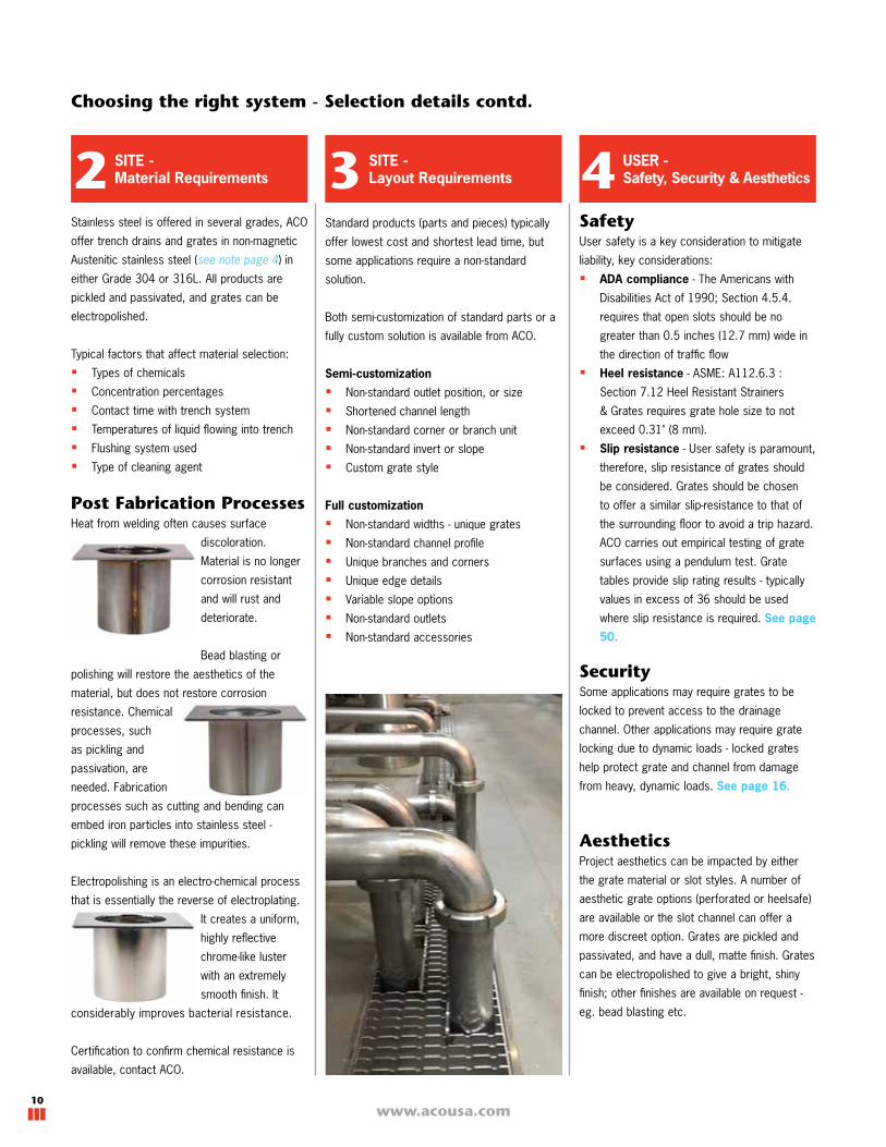
Post Fabrication ProcessesHeat from welding often causes surface
discoloration.
Material is no longer
corrosion resistant
and will rust and
deteriorate.
Bead blasting or
polishing will restore the aesthetics of the
material, but does not restore corrosion
resistance. Chemical
processes, such
as pickling and
passivation, are
needed. Fabrication
processes such as cutting and bending can
embed iron particles into stainless steel -
pickling will remove these impurities.
Electropolishing is an electro-chemical process
that is essentially the reverse of electroplating.
It creates a uniform,
highly reflective
chrome-like luster
with an extremely
smooth finish. It
considerably improves bacterial resistance.
Certification to confirm chemical resistance is
available, contact ACO.
Choosing the right system - Selection details contd.
2 3 USER - Safety, Security & Aesthetics4SITE -
Material RequirementsSITE - Layout Requirements
SecuritySome applications may require grates to be
locked to prevent access to the drainage
channel. Other applications may require grate
locking due to dynamic loads - locked grates
help protect grate and channel from damage
from heavy, dynamic loads. See page 16.
SafetyUser safety is a key consideration to mitigate
liability, key considerations:
� ADA compliance - The Americans with
Disabilities Act of 1990; Section 4.5.4.
requires that open slots should be no
greater than 0.5 inches (12.7 mm) wide in
the direction of traffic flow
� Heel resistance - ASME: A112.6.3 :
Section 7.12 Heel Resistant Strainers
& Grates requires grate hole size to not
exceed 0.31" (8 mm).
� Slip resistance - User safety is paramount,
therefore, slip resistance of grates should
be considered. Grates should be chosen
to offer a similar slip-resistance to that of
the surrounding floor to avoid a trip hazard.
ACO carries out empirical testing of grate
surfaces using a pendulum test. Grate
tables provide slip rating results - typically
values in excess of 36 should be used
where slip resistance is required. See page
50.
AestheticsProject aesthetics can be impacted by either
the grate material or slot styles. A number of
aesthetic grate options (perforated or heelsafe)
are available or the slot channel can offer a
more discreet option. Grates are pickled and
passivated, and have a dull, matte finish. Grates
can be electropolished to give a bright, shiny
finish; other finishes are available on request -
eg. bead blasting etc.
Standard products (parts and pieces) typically
offer lowest cost and shortest lead time, but
some applications require a non-standard
solution.
Both semi-customization of standard parts or a
fully custom solution is available from ACO.
Semi-customization
� Non-standard outlet position, or size
� Shortened channel length
� Non-standard corner or branch unit
� Non-standard invert or slope
� Custom grate style
Full customization
� Non-standard widths - unique grates
� Non-standard channel profile
� Unique branches and corners
� Unique edge details
� Variable slope options
� Non-standard outlets
� Non-standard accessories

11
ACO STAINLESS TRENCH
www.acousa.com
The volume of liquid a trench system needs
to collect and remove in a given time period
determines its minimum size.
The clear internal width and depth of a trench
drain determines its area available for flow.
Depth restrictions may limit maximum trench
depth leaving width as the only variable.
Slope increases liquid velocity providing a more
efficient trench. Constant depth channels are
suitable for restricted depth applications.
Grate intake: In some applications, grates can
be exposed to high water flows. Different open
area ratios can sometimes affect how quickly
liquids can enter the trench drain. ACO can
advise on grate intake performance
ACO offers different sized trench systems
and a broad selection of grates to meet most
hydraulic requirements.
A technical support service is available to help
ensure correct system specification.
HYDRAULICS - Volume of Liquid5 HYDRAULICS -
Outlet Type & Position6
Constant depth channels
Sloping channels
Type, size, position and number of outlets
is critical to efficient drainage of the trench
system. A number of options exist:
End outlet plate - pipe connected
horizontally at the end of the trench.
Minimizes excavation but offers
lowest outlet capacity.
Outlet channel - connect to waste system via
direct pipe connection, P-trap, or floor drain
body (required if floor membrane used).
Floor drain channel - offers connection to
larger outlet pipes, option of larger silt bakets if
run-off contains large amounts of debris
Floor drain top channel Outlet channel
Silt basketReduces flow and requires regular
maintenance
Direct push pipe
connection - See
ACO Pipe catalog
P-trap connection -
See ACO Pipe catalog
Floor drain body
- See pages 42
Areaavailablefor flow
Overall trench width
Clear opening width
Invert depth

www.acousa.com12
Modular Channel Systems
Modular 125 ...................................................... 18Modular 200 ...................................................... 26Floor Drain Bodies ............................................ 41
www.acousa.com12

13
ACO STAINLESS TRENCH
www.acousa.com
F
A
D
A
A
B
C E
F
F
D
ACO Modular 200ACO Modular 125
Modular Channel Systems
ACO Modular channels are available in AISI 304
or AISI 316L stainless steel with either a 4.92"
(125 mm) or 7.87" (200 mm) grate width. A
number of different grate styles and loadings are
available to suit any application - locking grates
are also available.
The constant depth or sloping system is
manufactured with a variety of different outlet
options to suit various applications and flow
requirements. Outlet units provide direct pipe
connection, P-trap connection or floor drain
body connection.
The modular format of the drain offers easy
layout configuration, transportation
and installation.
D
Straight channel ........................ pg 19/27
Corner channel.......................... pg 20/28
Branch channel ......................... pg 20/28
Outlet channel ........................... pg 21/29
Grate ........................................ pg 24/32
Silt basket ................................ pg 23/31
Gasket ..................................... pg 23/31
Floor Drain body ..............................pg 41
B
C
E
H
G
G
G
7.87” (200mm)
9.06” (230mm)
6.77” (172mm)
4.92” (125mm)
6.02” (153mm)
3.82” (97mm)
H
Semi-Customized ChannelsACO's Modular channels (straight units only)
can be customized to length to fit specific
configurations. A grate of same length is also
produced.
Customizations:
�Outlet position along channel
�Shortened channel length
�Non-standard junction layout
�Grate locking
�Edge detail
For projects that require a specific size, shape
or layout that cannot be achieved with a semi-
custom solution, ACO can manufacture a full-
custom product. See page 46.
H

www.acousa.com14
ACO Modular Features & Benefits
4.92" (125 mm) or 7.87" (200 mm) wide
channels
Flexible, off the shelf drainage solution available in:
� Constant depth or sloping straight units
� Corner units
� Branch units
� Various outlet options
Channel edge
Modular channels come standard with a solid rubber
edge in-fill. If a solid stainless steel in-fill is required,
please contact ACO. Load class or flooring type may
determine the edge in-fill choice.
Edge in-fill ensures stable and
durable transition of applied
loads between the trench
and surrounding floor,
which helps minimize
risk of floor cracks that
can harbor microorganisms.
Different edge details are available to suit different
types of floor finishes - See page 9.
V-bottom channel profile
Offers enhanced flow efficiency at low
flow rates and improved self cleaning
performance.
98ft (30m) continuous 0.5% slope to center outlet
Grate lockings
For applications where locked grates are required, ACO
Modular channel systems can be supplied with factory
fitted standard lockings (activated by a standard hexagon
wrench) or security locking (activated by a security
wrench). Channel section with optional grate locking
detail shown below. See pages 16-17 for details.
15
ACO STAINLESS TRENCH
www.acousa.com
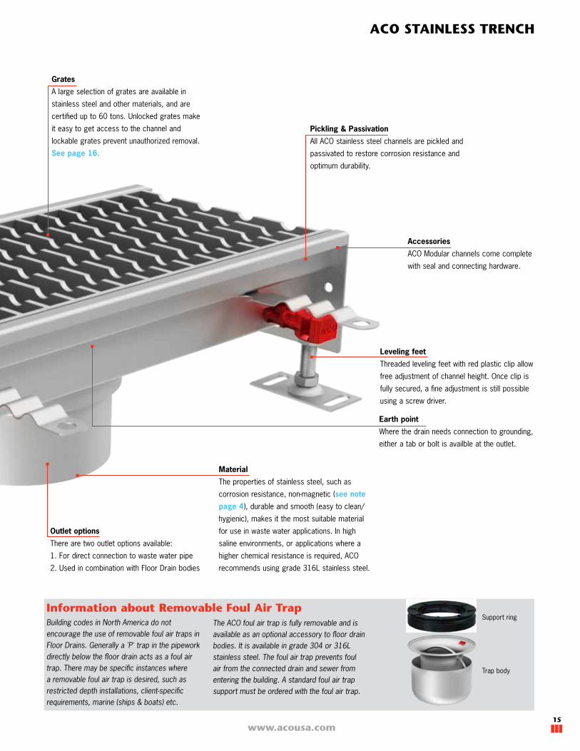
Leveling feet
Threaded leveling feet with red plastic clip allow
free adjustment of channel height. Once clip is
fully secured, a fine adjustment is still possible
using a screw driver.
Material
The properties of stainless steel, such as
corrosion resistance, non-magnetic (see note
page 4), durable and smooth (easy to clean/
hygienic), makes it the most suitable material
for use in waste water applications. In high
saline environments, or applications where a
higher chemical resistance is required, ACO
recommends using grade 316L stainless steel.
Pickling & Passivation
All ACO stainless steel channels are pickled and
passivated to restore corrosion resistance and
optimum durability.
Outlet options
There are two outlet options available:
1. For direct connection to waste water pipe
2. Used in combination with Floor Drain bodies
Accessories
ACO Modular channels come complete
with seal and connecting hardware.
Grates
A large selection of grates are available in
stainless steel and other materials, and are
certified up to 60 tons. Unlocked grates make
it easy to get access to the channel and
lockable grates prevent unauthorized removal.
See page 16.
Building codes in North America do not encourage the use of removable foul air traps in Floor Drains. Generally a 'P' trap in the pipework directly below the floor drain acts as a foul air trap. There may be specific instances where a removable foul air trap is desired, such as restricted depth installations, client-specific requirements, marine (ships & boats) etc.
The ACO foul air trap is fully removable and is available as an optional accessory to floor drain bodies. It is available in grade 304 or 316L stainless steel. The foul air trap prevents foul air from the connected drain and sewer from entering the building. A standard foul air trap support must be ordered with the foul air trap.
Information about Removable Foul Air Trap
Trap body
Support ring
Earth point
Where the drain needs connection to grounding,
either a tab or bolt is availble at the outlet.

www.acousa.com16
ACO Modular Grate Lockings
For applications where locked grates are required, the ACO Modular channel systems can be supplied with factory fitted standard lockings (activated by
a standard hexagon wrench) or security locking (activated by a security wrench).
Notes:
1. Channel systems required with locking accessory require appropriate grate recess. If locking recess is not standard, modification will be required.
2. Floor Drain grates will be modified at the factory for locking as part of the Floor Drain locking kit.
3. Locking kits include channel floor drain modification locking bar and fixing (four bolt lengths supplied in kit).
4. Appropriate standard or security locking wrench to be ordered separately.
Hexagonal or security bolt
Locking nut and carrier
welded to base of channel.
Locking turnbuckleLocking studs
welded to side of channel wall.
Grate
Channel
Grate
Channel
Lockings Details
Shallow Channel
Standard Channel
ACO Modular 125 Grate Locking Kits
Part # Description Unit
142665 Standard Modular 125 M8 Locking Kit - M8 - 1.25 One locking per 19.69" (500 mm) grate. Meter grates require
2 units142666 Security Modular 125 M8 Locking Kit - M8 - 1.25
142667 Standard Hexagon Locking Wrench to fit M8 -
142668 Security Hexagon Locking Wrench to fit M8 -
ACO Modular 200 Grate Locking Kits
142665 Standard Modular 200 M8 Locking Kit - M8 - 1.25 One locking per 19.69" (500 mm) grate. Meter grates require
2 units142666 Security Modular 200 M8 Locking Kit - M8 - 1.25
142667 Standard Hexagon Locking Wrench to fit M8 -
142668 Security Hexagon Locking Wrench to fit M8 -
Hexagonal or security bolt
Locking bolt with wrench Example of a security bolt
Example of a standard bolt
17
ACO STAINLESS TRENCH
www.acousa.com
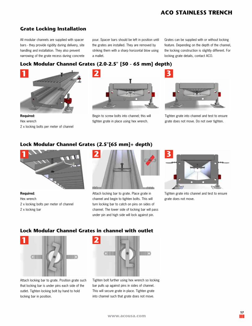
Grate Locking Installation
All modular channels are supplied with spacer
bars - they provide rigidity during delivery, site
handling and installation. They also prevent
narrowing of the grate recess during concrete
pour. Spacer bars should be left in position until
the grates are installed. They are removed by
striking them with a sharp horizontal blow using
a mallet.
Grates can be supplied with or without locking
feature. Depending on the depth of the channel,
the locking construction is slightly different. For
locking grate details, contact ACO.
Lock Modular Channel Grates (2.0-2.5" [50 - 65 mm] depth)
Lock Modular Channel Grates (2.5"[65 mm]+ depth)
Lock Modular Channel Grates in channel with outlet
Required:
Hex wrench
2 x locking bolts per meter of channel
Begin to screw bolts into channel; this will
tighten grate in place using hex wrench.
Tighten grate into channel and test to ensure
grate does not move. Do not over tighten.
Required:
Hex wrench
2 x locking bolts per meter of channel
2 x locking bar
Attach locking bar to grate. Place grate in
channel and begin to tighten bolts. This will
turn locking bar to catch on pins on sides of
channel. The lower side of locking bar will pass
under pin and high side will lock against pin.
Tighten grate into channel and test to ensure
grate does not move.
Attach locking bar to grate. Position grate such
that locking bar is under pins each side of the
outlet. Tighten locking bolt by hand to hold
locking bar in position.
Tighten bolt further using hex wrench so locking
bar pulls up against pins in sides of channel.
This will secure grate in place. Tighten grate
into channel such that grate does not move.
2 3
2
2 3
www.acousa.com18
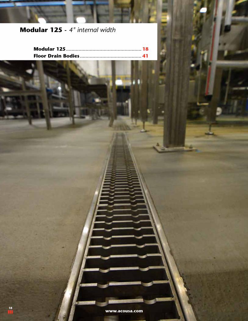
Modular 125 - 4" internal width
Modular 125 ...................................................... 18Floor Drain Bodies ............................................ 41
www.acousa.com18

19
ACO STAINLESS TRENCH
www.acousa.com
Lengthin (mm)
Invertin (mm)
Part #
AISI 304 AISI 316L
19.69 (500)
1.97 (50) 105119 407211
2.56 (65) 105120 407212
3.15 (80) 105121 407213
3.74 (95) 105122 407214
4.33 (110) 105123 407215
4.92 (125) 105124 407216
39.37 (1000)
1.97 (50) 105127 407217
2.56 (65) 105128 407218
3.15 (80) 105129 407219
3.74 (95) 105130 407220
4.33 (110) 105131 407221
4.92 (125) 105132 407222
78.74 (2000)
1.97 (50) 105135 407223
2.56 (65) 105136 407224
3.15 (80) 105137 407225
3.74 (95) 105138 407226
4.33 (110) 105139 407227
4.92 (125) 105140 407228
118.11 (3000)
1.97 (50) 105143 407229
2.56 (65) 105144 407230
3.15 (80) 105145 407231
3.74 (95) 105146 407232
4.33 (110) 105147 407233
4.92 (125) 105148 407234
Neutral invert Channel
Modular 125 Parts Tables
Lengthin (mm)
Slope%
Invert 1in (mm)
Invert 2in (mm)
Part #
AISI 304 AISI 316L
19.69 (500) 3.0
1.97 (50) 2.56 (65) 105151 407235
2.56 (65) 3.15 (80) 105152 407236
3.15 (80) 3.74 (95) 142726 142686
3.74 (95) 4.33 (110) 142727 142687
39.37 (1000) 1.5
1.97 (50) 2.56 (65) 105155 407237
2.56 (65) 3.15 (80) 105156 407238
3.15 (80) 3.74 (95) 105157 407239
3.74 (95) 4.33 (110) 105158 407240
78.74 (2000) 0.75
1.97 (50) 2.56 (65) 105161 407241
2.56 (65) 3.15 (80) 105162 407242
3.15 (80) 3.74 (95) 105163 407243
3.74 (95) 4.33 (110) 105164 407244
4.33 (110) 4.92 (125) 105165 407245
118.11 (3000) 0.5
1.97 (50) 2.56 (65) 105168 407246
2.56 (65) 3.15 (80) 105169 407247
3.15 (80) 3.74 (95) 105170 407248
3.74 (95) 4.33 (110) 105171 407249
4.33 (110) 4.92 (125) 105172 407250
Sloping Invert Channel
Length
Inve
rt
Length
Inve
rt 1
Inve
rt 2
Notes: Channels supplied with gasket and hardware to suit deeper end of unit.
A
A

www.acousa.com20
Length 1
Leng
th 2
Modular 125 Parts Tables
Length 1in (mm)
Length 2in (mm)
Gratesize
Invertin (mm)
Part #
AISI 304 AISI 316L
19.69 (500) 20.28 (515)1 Qty 19.69" (500)1 Qty 14.76" (375)
See page 24
1.97 (50) 409824 409830
2.56 (65) 409825 409831
3.15 (80) 409826 409832
3.74 (95) 409827 409833
4.33 (110) 409828 409834
4.92 (125) 409829 409835
Branch Channel
Corner Channel Length 1in (mm)
Length 2in (mm)
Gratesize
Invertin (mm)
Part #
AISI 304 AISI 316L
20.28 (515) 20.28 (515)1 Qty 19.69" (500)1 Qty 14.76" (375)
See page 24
1.97 (50) 409812 409818
2.56 (65) 409813 409819
3.15 (80) 409814 409820
3.74 (95) 409815 409821
4.33 (110) 409816 409822
4.92 (125) 409817 409823
Length 1
Leng
th 2
B
C
Notes: Channels supplied with gasket & hardware to suit deeper end of unit.Branch channels may need an additional gasket to be purchased depending upon layout
500mm grate
375m
m g
rate
500mm grate
375m
m g
rate
21
ACO STAINLESS TRENCH
www.acousa.com
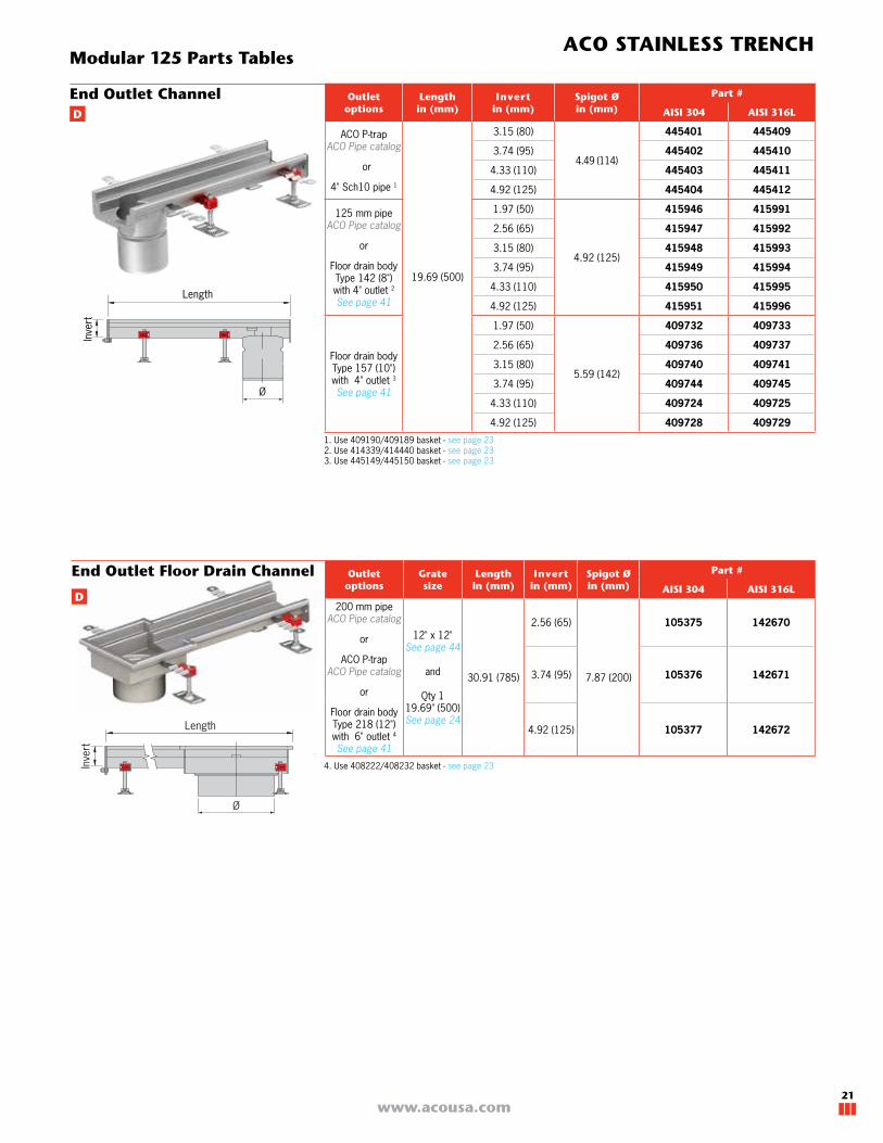
Modular 125 Parts Tables
Outlet options
Lengthin (mm)
Invertin (mm)
Spigot Øin (mm)
Part #
AISI 304 AISI 316L
ACO P-trap ACO Pipe catalog
or
4" Sch10 pipe 1
19.69 (500)
3.15 (80)
4.49 (114)
445401 445409
3.74 (95) 445402 445410
4.33 (110) 445403 445411
4.92 (125) 445404 445412
125 mm pipeACO Pipe catalog
or
Floor drain body Type 142 (8") with 4" outlet 2 See page 41
1.97 (50)
4.92 (125)
415946 415991
2.56 (65) 415947 415992
3.15 (80) 415948 415993
3.74 (95) 415949 415994
4.33 (110) 415950 415995
4.92 (125) 415951 415996
Floor drain body Type 157 (10") with 4" outlet 3 See page 41
1.97 (50)
5.59 (142)
409732 409733
2.56 (65) 409736 409737
3.15 (80) 409740 409741
3.74 (95) 409744 409745
4.33 (110) 409724 409725
4.92 (125) 409728 409729
End Outlet Channel
Ø
Inve
rt
Length
D
End Outlet Floor Drain Channel
D
Outlet options
Gratesize
Lengthin (mm)
Invertin (mm)
Spigot Øin (mm)
Part #
AISI 304 AISI 316L
200 mm pipe ACO Pipe catalog
or
ACO P-trap ACO Pipe catalog
or
Floor drain body Type 218 (12") with 6" outlet 4 See page 41
12" x 12"See page 44
and
Qty 119.69" (500)See page 24
30.91 (785)
2.56 (65)
7.87 (200)
105375 142670
3.74 (95) 105376 142671
4.92 (125) 105377 142672
Ø
Inve
rt
Length
4. Use 408222/408232 basket - see page 23
1. Use 409190/409189 basket - see page 232. Use 414339/414440 basket - see page 233. Use 445149/445150 basket - see page 23

www.acousa.com22
Modular 125 Parts Tables
D
4. Use 408222/408232 basket - see page 23
Outlet options
Gratesize
Lengthin (mm)
Invertin
(mm)
Spigot Øin (mm)
Part #
AISI 304 AISI 316L
200 mm pipe ACO Pipe catalog
or
ACO P-trap ACO Pipe catalog
or
Floor drain body Type 218 (12") with 6" outlet 4 See page 41
12" x 12"See page 44
and
Qty 219.69" (500)See page 24
50.0 (1270)
2.56 (65)
7.87 (200)
105378 142673
3.74 (95) 105379 142674
4.92 (125) 105380 142675
Center Floor Drain Outlet Channel
Ø
Inve
rt
Length
Center Outlet Channel
Ø
Inve
rt
Length
Notes: Channels supplied with gasket and hardware to suit deeper end of unit.Refer to page 41-45 for floor drain bodies and grates.
D
Outlet options
Lengthin (mm)
Invertin (mm)
Spigot Øin (mm)
Part #
AISI 304 AISI 316L
ACO P-trap ACO Pipe catalog
or
4" Sch10 pipe 1
19.69 (500)
3.15 (80)
4.49 (114)
445405 445413
3.74 (95) 445406 445414
4.33 (110) 445407 445415
4.92 (125) 445408 445416
125 mm pipeACO Pipe catalog
or
Floor drain body Type 142 (8") with 4" outlet 2 See page 41
1.97 (50)
4.92 (125)
415958 416003
2.56 (65) 415959 416004
3.15 (80) 415960 416005
3.74 (95) 415961 416006
4.33 (110) 415962 416007
4.92 (125) 415963 416008
Floor drain body Type 157 (10") with 4" outlet 3 See page 41
1.97 (50)
5.59 (142)
409734 409735
2.56 (65) 409738 409739
3.15 (80) 409742 409743
3.74 (95) 409746 409747
4.33 (110) 409726 409727
4.92 (125) 409730 409731
1. Use 409190/409189 basket - see page 232. Use 414339/414440 basket - see page 233. Use 445149/445150 basket - see page 23
23
ACO STAINLESS TRENCH
www.acousa.com
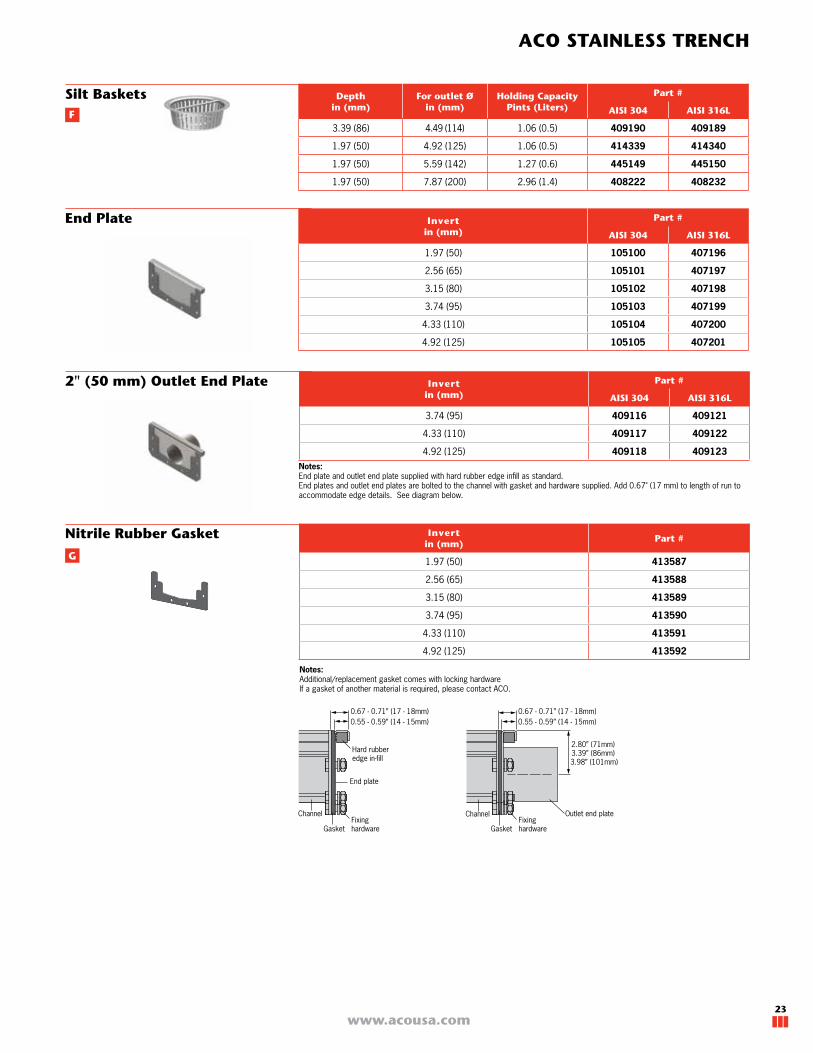
Depthin (mm)
For outlet Øin (mm)
Holding CapacityPints (Liters)
Part #
AISI 304 AISI 316L
3.39 (86) 4.49 (114) 1.06 (0.5) 409190 409189
1.97 (50) 4.92 (125) 1.06 (0.5) 414339 414340
1.97 (50) 5.59 (142) 1.27 (0.6) 445149 445150
1.97 (50) 7.87 (200) 2.96 (1.4) 408222 408232
Invertin (mm)
Part #
AISI 304 AISI 316L
1.97 (50) 105100 407196
2.56 (65) 105101 407197
3.15 (80) 105102 407198
3.74 (95) 105103 407199
4.33 (110) 105104 407200
4.92 (125) 105105 407201
Silt Baskets
End Plate
Invertin (mm)
Part #
AISI 304 AISI 316L
3.74 (95) 409116 409121
4.33 (110) 409117 409122
4.92 (125) 409118 409123
2" (50 mm) Outlet End Plate
Nitrile Rubber Gasket
Notes: End plate and outlet end plate supplied with hard rubber edge infill as standard.End plates and outlet end plates are bolted to the channel with gasket and hardware supplied. Add 0.67" (17 mm) to length of run to accommodate edge details. See diagram below.
0.55 - 0.59” (14 - 15mm)0.67 - 0.71” (17 - 18mm)
0.55 - 0.59” (14 - 15mm)
Channel
Gasket
End plate
Hard rubberedge in-fill
Fixinghardware
Channel
Gasket
Outlet end plateFixinghardware
0.67 - 0.71” (17 - 18mm)
2.80” (71mm)3.39” (86mm)
3.98” (101mm)
F
G
Notes: Additional/replacement gasket comes with locking hardwareIf a gasket of another material is required, please contact ACO.
Invertin (mm)
Part #
1.97 (50) 413587
2.56 (65) 413588
3.15 (80) 413589
3.74 (95) 413590
4.33 (110) 413591
4.92 (125) 413592

www.acousa.com24
Modular 125 Grates Parts Tables
Mesh Grate
Heelsafe Grate
Multi-Slot 5 Grate
Perforated Grate
Ladder Grate
Lengthin (mm)
Load classSlip
resistanceOpen area
sq in
Part #
EN 1433 ASME EN 1253AISI 304 AISI 316L
Non-Locking
Locking Non-Locking
Locking
14.76 (375)
A15 LD L15
14.6 414139 n/a 414189 n/a
19.69 (500) 19.6 409290 n/a 409291 n/a
39.37 (1000) 33.6 409286 n/a 409287 n/a
19.69 (500)B125 MD R50
19.6 409294 n/a 409295 n/a
39.37 (1000) 33.6 409236 n/a 409237 n/a
E
Lengthin (mm)
Load classSlip
resistanceOpen area
sq in
Part #
EN 1433 ASME EN 1253AISI 304 AISI 316L
Non-Locking
Locking Non-Locking
Locking
14.76 (375)
B125 MD R50
29.0 414135 n/a 414185 n/a
19.69 (500) 38.8 96819 n/a 401238 n/a
39.37 (1000) 78.1 96818 n/a 401237 n/a
Lengthin (mm)
Load classSlip
resistanceOpen area
sq in
Part #
EN 1433 ASME EN 1253AISI 304 AISI 316L
Non-Locking
Locking Non-Locking
Locking
14.76 (375)
A15 LD L15
57.8 414130 n/a 414180 n/a
19.69 (500) 77.5 21710 n/a 21715 n/a
39.37 (1000) 156.6 21610 n/a 21615 n/a
14.76 (375)
C250 MD-HD M125
51.8 414131 n/a 414181 n/a
19.69 (500) 69.8 21910 n/a 21915 n/a
39.37 (1000) 146.9 21810 n/a 21815 n/a
Lengthin (mm)
Load classSlip
resistanceOpen area
sq in *
Part #
EN 1433 ASME EN 1253AISI 304 AISI 316L
Non-Locking
Locking Non-Locking
Locking
14.76 (375)
A15 LD L15
38.2 414136 n/a 414186 n/a
19.69 (500) 50.2 21760 n/a 21765 n/a
39.37 (1000) 101.3 21660 n/a 21665 n/a
19.69 (500)C250 MD-HD M125
50.2 21960 105504 21965 142504
39.37 (1000) 101.3 21860 105505 21865 142505
Lengthin (mm)
Load classSlip
resistanceOpen area
sq in
Part #
EN 1433 ASME EN 1253AISI 304 AISI 316L
Non-Locking
Locking Non-Locking
Locking
14.76 (375)
C250 MD-HD M125
52.4 414134 142506 414184 142507
19.69 (500) 69.3 21740 142508 21745 142509
39.37 (1000) 139.2 21741 142510 21746 142511
14.76 (375)
E600 XHD P400
34.7 138222 142512 138225 142513
19.69 (500) 46.2 138223 142514 138226 142515
39.37 (1000) 94.4 138224 142516 138227 142517
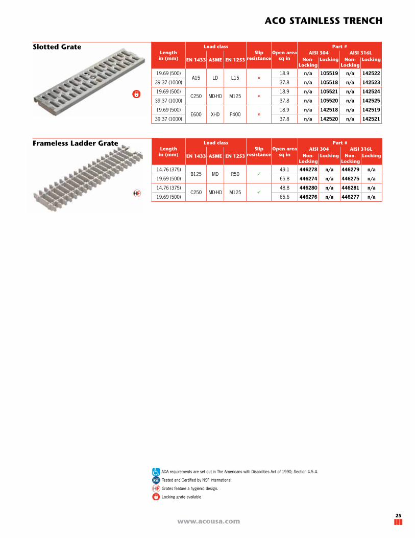
Tested and Certified by NSF International.
Grates feature a hygienic design.
ADA requirements are set out in The Americans with Disabilities Act of 1990; Section 4.5.4.
Locking grate available
* Locking will reduce open area by 1.04 sq in
25
ACO STAINLESS TRENCH
www.acousa.com
Tested and Certified by NSF International.
Grates feature a hygienic design.
ADA requirements are set out in The Americans with Disabilities Act of 1990; Section 4.5.4.
Locking grate available
Slotted Grate
Frameless Ladder GrateLengthin (mm)
Load classSlip
resistanceOpen area
sq in
Part #
EN 1433 ASME EN 1253AISI 304 AISI 316L
Non-Locking
Locking Non-Locking
Locking
14.76 (375)B125 MD R50
49.1 446278 n/a 446279 n/a
19.69 (500) 65.8 446274 n/a 446275 n/a
14.76 (375)C250 MD-HD M125
48.8 446280 n/a 446281 n/a
19.69 (500) 65.6 446276 n/a 446277 n/a
Lengthin (mm)
Load classSlip
resistanceOpen area
sq in
Part #
EN 1433 ASME EN 1253AISI 304 AISI 316L
Non-Locking
Locking Non-Locking
Locking
19.69 (500)A15 LD L15
18.9 n/a 105519 n/a 142522
39.37 (1000) 37.8 n/a 105518 n/a 142523
19.69 (500)C250 MD-HD M125
18.9 n/a 105521 n/a 142524
39.37 (1000) 37.8 n/a 105520 n/a 142525
19.69 (500)E600 XHD P400
18.9 n/a 142518 n/a 142519
39.37 (1000) 37.8 n/a 142520 n/a 142521
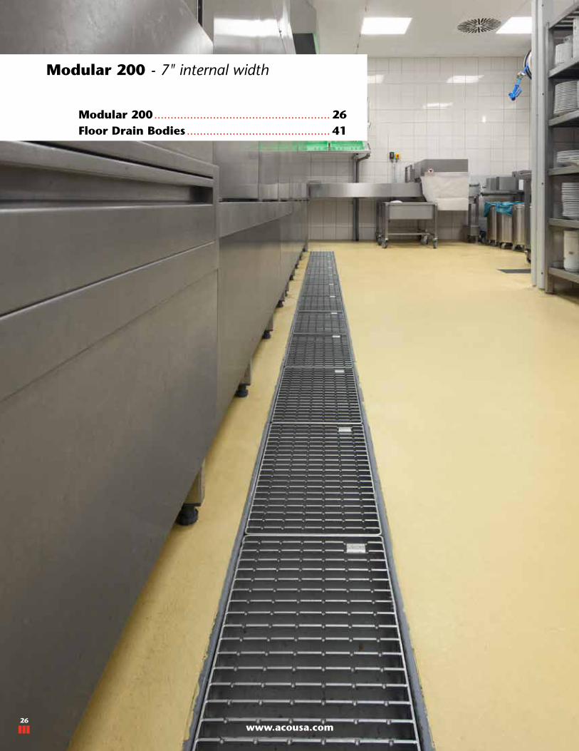
www.acousa.com26
Modular 200 - 7" internal width
Modular 200 ...................................................... 26Floor Drain Bodies ............................................ 41
www.acousa.com26

27
ACO STAINLESS TRENCH
www.acousa.com
Neutral Invert Channel
Modular 200 Parts Tables
Lengthin (mm)
Invertin (mm)
Part #
AISI 304 AISI 316L
19.69 (500)
2.36 (60) 409072 409050
2.76 (70) 409047 409051
3.15 (80) 409048 409052
3.94 (100) 409049 409053
39.37 (1000)
2.36 (60) 401859 401860
2.76 (70) 409054 409057
3.15 (80) 409055 409058
3.94 (100) 409056 409059
78.74 (2000)
2.36 (60) 401875 401876
2.76 (70) 409060 409063
3.15 (80) 409061 409064
3.94 (100) 409062 409065
118.11 (3000)
2.36 (60) 401895 401896
2.76 (70) 409066 409069
3.15 (80) 409067 409070
3.94 (100) 409068 409071
Lengthin (mm)
Slope%
Invert 1in (mm)
Invert 2in (mm)
Part #
AISI 304 AISI 316L
19.69 (500) 1.0 2.17 (55) 2.36 (60) 401855 401856
39.37 (1000) 1.0
2.36 (60) 2.76 (70) 401871 401872
2.76 (70) 3.15 (80) 402464 402465
3.15 (80) 3.54 (90) 402466 402467
3.54 (90) 3.94 (100) 402468 402469
3.94 (100) 4.33 (110) 402470 402471
78.74 (2000) 0.5
2.36 (60) 2.76 (70) 401887 401888
2.76 (70) 3.15 (80) 402472 402473
3.15 (80) 3.54 (90) 402474 402475
3.54 (90) 3.94 (100) 402476 402477
3.94 (100) 4.33 (110) 402478 402479
4.33 (110) 4.72 (120) 402480 402481
118.11 (3000) 0.67
2.36 (60) 3.15 (80) 402482 402483
3.15 (80) 3.94 (100) 402484 402485
3.94 (100) 4.72 (120) 402486 402487
4.72 (120) 5.51 (140) 402488 402489
Sloping Invert Channel
Notes: Channels supplied with gasket & hardware to suit deeper end of unit.
Length
Inve
rt
Length
Inve
rt 1
Inve
rt 2
A
A

www.acousa.com28
Modular 200 Parts Tables
Branch Channel
Length1
Leng
th 2
Corner Channel
Length2
Leng
th1
B
C
Length 1in (mm)
Length 2in (mm)
Gratesize
Invertin (mm)
Part #
AISI 304 AISI 316L
19.69 (500) 20.28 (515)1 Qty 19.69" (500)1 Qty 11.81" (300)
See page 32
2.36 (60) 401933 401934
3.15 (80) 402494 402495
3.94 (100) 402496 402497
Length 1in (mm)
Length 2in (mm)
Gratesize
Invertin (mm)
Part #
AISI 304 AISI 316L
20.28 (515) 20.28 (515)1 Qty 19.69" (500)1 Qty 11.81" (300)
See page 32
2.36 (60) 401921 401922
3.15 (80) 402490 402491
3.94 (100) 402492 402493
Notes: Channels supplied with gasket & hardware to suit deeper end of unit.Branch channels may need an additional gasket to be purchased depending upon layout
500mm grate
300m
m g
rate
500mm grate
300m
m g
rate
29
ACO STAINLESS TRENCH
www.acousa.com
Ø
Inve
rt
Length
Ø
Inve
rt
Length
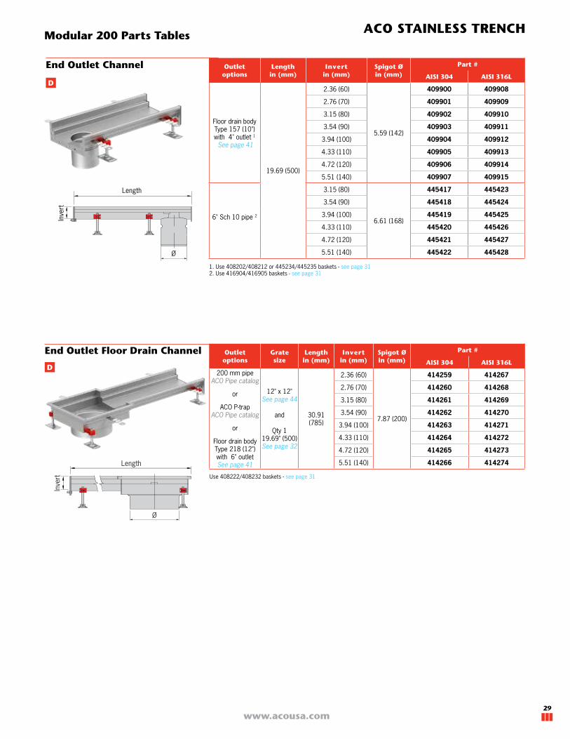
End Outlet Channel Outlet options
Lengthin (mm)
Invertin (mm)
Spigot Øin (mm)
Part #
AISI 304 AISI 316L
Floor drain body Type 157 (10") with 4" outlet 1
See page 41
19.69 (500)
2.36 (60)
5.59 (142)
409900 409908
2.76 (70) 409901 409909
3.15 (80) 409902 409910
3.54 (90) 409903 409911
3.94 (100) 409904 409912
4.33 (110) 409905 409913
4.72 (120) 409906 409914
5.51 (140) 409907 409915
6" Sch 10 pipe 2
3.15 (80)
6.61 (168)
445417 445423
3.54 (90) 445418 445424
3.94 (100) 445419 445425
4.33 (110) 445420 445426
4.72 (120) 445421 445427
5.51 (140) 445422 445428
Outlet options
Gratesize
Lengthin (mm)
Invertin (mm)
Spigot Øin (mm)
Part #
AISI 304 AISI 316L
200 mm pipe ACO Pipe catalog
or
ACO P-trap ACO Pipe catalog
or
Floor drain body Type 218 (12") with 6" outlet See page 41
12" x 12"See page 44
and
Qty 119.69" (500)See page 32
30.91 (785)
2.36 (60)
7.87 (200)
414259 414267
2.76 (70) 414260 414268
3.15 (80) 414261 414269
3.54 (90) 414262 414270
3.94 (100) 414263 414271
4.33 (110) 414264 414272
4.72 (120) 414265 414273
5.51 (140) 414266 414274
End Outlet Floor Drain Channel
Modular 200 Parts Tables
1. Use 408202/408212 or 445234/445235 baskets - see page 31 2. Use 416904/416905 baskets - see page 31
D
D
Use 408222/408232 baskets - see page 31

www.acousa.com30
Modular 200 Parts Tables
Ø
Inve
rt
Length
Center Outlet Channel
Outlet options
Gratesize
Lengthin (mm)
Invertin (mm)
Spigot Øin (mm)
Part #
AISI 304 AISI 316L
200 mm pipe ACO Pipe catalog
or
ACO P-trap ACO Pipe catalog
or
Floor drain body Type 218 (12") with 6" outlet See page 41
12" x 12"See page 44
and
Qty 119.69" (500)See page 32
50.00 (1270)
2.36 (60)
7.87 (200)
414243 414251
2.76 (70) 414244 414252
3.15 (80) 414245 414253
3.54 (90) 414246 414254
3.94 (100) 414247 414255
4.33 (110) 414248 414256
4.72 (120) 414249 414257
5.51 (140) 414250 414258
Outlet options
Lengthin (mm)
Invertin (mm)
Spigot Øin (mm)
Part #
AISI 304 AISI 316L
Floor drain body Type 157 (10") with 4" outlet 1
See page 41
19.69 (500)
2.36 (60)
5.59 (142)
409916 409924
2.76 (70) 409917 409925
3.15 (80) 409918 409926
3.54 (90) 409919 409927
3.94 (100) 409920 409928
4.33 (110) 409921 409929
4.72 (120) 409922 409930
5.51 (140) 409923 409931
6" Sch 10 pipe 2
3.15 (80)
6.61 (168)
445429 445435
3.54 (90) 445430 445436
3.94 (100) 445431 445437
4.33 (110) 445432 445438
4.72 (120) 445433 445439
5.51 (140) 445434 445440
Center Floor Drain Outlet Channel
Notes: Channels supplied with gasket and hardware to suit deeper end of unit.Refer to page 41-45 for floor drain bodies and grates.
Ø
Inve
rt
Length
D
D
1. Use 408202/408212 or 445234/445235 baskets - see page 31 2. Use 416904/416905 baskets - see page 31
Use 408222/408232 basket - see page 31
31
ACO STAINLESS TRENCH
www.acousa.com
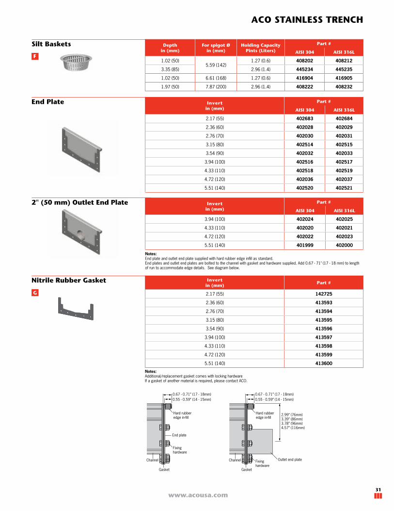
Notes: Additional/replacement gasket comes with locking hardwareIf a gasket of another material is required, please contact ACO.
Invertin (mm)
Part #
AISI 304 AISI 316L
2.17 (55) 402683 402684
2.36 (60) 402028 402029
2.76 (70) 402030 402031
3.15 (80) 402514 402515
3.54 (90) 402032 402033
3.94 (100) 402516 402517
4.33 (110) 402518 402519
4.72 (120) 402036 402037
5.51 (140) 402520 402521
End Plate
Invertin (mm)
Part #
AISI 304 AISI 316L
3.94 (100) 402024 402025
4.33 (110) 402020 402021
4.72 (120) 402022 402023
5.51 (140) 401999 402000
2" (50 mm) Outlet End Plate
Invertin (mm)
Part #
2.17 (55) 142725
2.36 (60) 413593
2.76 (70) 413594
3.15 (80) 413595
3.54 (90) 413596
3.94 (100) 413597
4.33 (110) 413598
4.72 (120) 413599
5.51 (140) 413600
Nitrile Rubber Gasket
Notes: End plate and outlet end plate supplied with hard rubber edge infill as standard.End plates and outlet end plates are bolted to the channel with gasket and hardware supplied. Add 0.67 - 71" (17 - 18 mm) to length of run to accommodate edge details. See diagram below.
Silt Baskets Depthin (mm)
For spigot Øin (mm)
Holding CapacityPints (Liters)
Part #
AISI 304 AISI 316L
1.02 (50)5.59 (142)
1.27 (0.6) 408202 408212
3.35 (85) 2.96 (1.4) 445234 445235
1.02 (50) 6.61 (168) 1.27 (0.6) 416904 416905
1.97 (50) 7.87 (200) 2.96 (1.4) 408222 408232
F
G
Outlet end plate
2.99” (76mm)3.39” (86mm)3.78” (96mm)4.57” (116mm)
0.55 - 0.59” (14 - 15mm)0.67 - 0.71” (17 - 18mm)
Channel
Gasket
End plate
Hard rubberedge in-fill
Fixinghardware
0.55 - 0.59” (14 - 15mm)0.67 - 0.71” (17 - 18mm)
Channel
Gasket
Hard rubberedge in-fill
Fixinghardware

www.acousa.com32
Mesh Grate
Modular 200 Grates Parts Tables
Multi-Slot 5 Grate
E
Heelsafe Grate
Lengthin (mm)
Load classSlip
resistanceOpen area
sq in
Part #
EN 1433 ASME EN 1253AISI 304 AISI 316L
Non-Locking
Locking Non-Locking
Locking
11.81 (300)
A15 LD L15
67.0 414140 n/a 414190 n/a
19.69 (500) 127.6 92200 n/a 92250 n/a
39.37 (1000) 256.0 92201 n/a 92251 n/a
Lengthin (mm)
Load classSlip
resistanceOpen area
sq in
Part #
EN 1433 ASME EN 1253AISI 304 AISI 316L
Non-Locking
Locking Non-Locking
Locking
11.81 (300)
A15 LD L15
40.3 142526 n/a 142527 n/a
19.69 (500) 67.1 142528 n/a 142529 n/a
39.37 (1000) 134.2 142530 n/a 142531 n/a
Lengthin (mm)
Load classSlip
resistanceOpen area
sq in
Part #
EN 1433 ASME EN 1253AISI 304 AISI 316L
Non-Locking
Locking Non-Locking
Locking
11.81 (300)
A15 LD L15
20.6 414145 n/a 414195 n/a
19.69 (500) 31.4 409292 n/a 409293 n/a
39.37 (1000) 53.5 409288 n/a 409289 n/a
19.69 (500)B125 MD R50
31.4 409296 n/a 409297 n/a
39.37 (1000) 53.5 409240 n/a 409241 n/a
Items shown with the NSF Mark have been tested and Certified by NSF International.
Grates shown with this mark feature a hygienic design.
ADA requirements are set out in The Americans with Disabilities Act of 1990; Section 4.5.4.
Grates shown with this mark can have locking added
Frameless Ladder GrateLengthin (mm)
Load classSlip
resistanceOpen area
sq in
Part #
EN 1433
ASME EN 1253AISI 304 AISI 316L
Non-Locking
Locking Non-Locking
Locking
11.81 (300)A15 LD L15
68.0 446250 n/a 446251 n/a
19.69 (500) 114.1 446246 n/a 446247 n/a
11.81 (300)C250 MD-HD M125
64.6 446252 n/a 446253 n/a
19.69 (500) 108.3 446248 n/a 446249 n/a

33
ACO STAINLESS TRENCH
www.acousa.com
Ladder Grate
Perforated Grate
Items shown with the NSF Mark have been tested and Certified by NSF International.
Grates shown with this mark feature a hygienic design.
ADA requirements are set out in The Americans with Disabilities Act of 1990; Section 4.5.4.
Grates shown with this mark can have locking added
Lengthin (mm)
Load classSlip
resistanceOpen area
sq in
Part #
EN 1433 ASME EN 1253AISI 304 AISI 316L
Non-Locking
Locking Non-Locking
Locking
11.81 (300)
A15 LD L15
15.6 414143 142532 414193 142533
19.69 (500) 26.0 402689 142534 405188 142535
39.37 (1000) 52.7 402688 142536 405187 142537
Lengthin (mm)
Load classSlip
resistanceOpen area
sq in
Part #
EN 1433
ASMEEN
1253
AISI 304 AISI 316LNon-
LockingLocking Non-
LockingLocking
39.37 (1000) A15 LD L15 201.0 445948 142538 445949 142539
11.81 (300)
C250 MD-HD M125
69.6 414142 142540 414192 142541
19.69 (500) 114.7 92214 142542 92264 142543
39.37 (1000) 231.3 92215 142544 92265 142545
11.81 (300)
E600 XHD P400
47.9 138228 142546 138231 142547
19.69 (500) 79.9 138229 142548 138232 142549
39.37 (1000) 159.7 138230 142550 138233 142551
Portable Tundish Depthin (mm)
Widthin (mm)
Part #
AISI 304 AISI 316L
9.84 (250) 9.84 (250) 415821 n/a

www.acousa.com34
Slot Drain 20 - 2½" internal width
Slot Drains ......................................................... 34Floor Drain Bodies ............................................ 41
www.acousa.com34

35
ACO STAINLESS TRENCH
www.acousa.com
ACO Slot Drain 20
ACO Slot Drain 20 is available in AISI 304 or
AISI 316 stainless steel offering a 0.79" (20
mm) central slot. The constant depth or sloping
system is manufactured with a central slot for
water capture and is available with corner and
branch channels.
The modular format of the ACO Slot Drain 20
offers easy layout configuration, transportation
and installation.
The continuous 0.79" (20 mm) slot allows for
easy cleaning. Flange and gasket connections
offer a secure seal.
Outlet units provide access to the channel and can be direct pipe connection, P-trap connection or floor drain connection (usually where floor membrane used). A choice of grates is available
for these units - See page 44.
ACO Slot Drain 20
1.97” (50mm)
0.79” (20mm)
2.44” (62mm)
F
A
D
Straight channel ..............................pg 38
Corner unit .....................................pg 38
Branch unit .....................................pg 39
Outlet unit .......................................pg 39
Grate ..............................................pg 44
Silt basket ......................................pg 40
Gasket ...........................................pg 40
Floor Drain body ..............................pg 41
B
C
E
H
G
A
A
B
C
D
D
E
E
F
F
H
G
H
Semi-Customized Slot Drain
The dimensions of the ACO Slot Drain 20 can
be made semi-custom to meet specific project
requirements.
Customizations:
�Slot width can be adjusted between 0.375"
(8 mm) and 0.8" (20 mm) wide
�Length can be fully customized.
�Longitudinal slope of bottom invert can be
customized between 1% and 5%
�Outlet position customized along length.
�ADA/Heelsafe compliant slot can be
created selecting a custom sized slot or by
adding a toe-bar - See page 47.
Projects that require a specific size, shape or
layout that cannot be achieved with a semi-
custom solution, ACO can manufacture a full-
custom product. See page 46.
www.acousa.com36
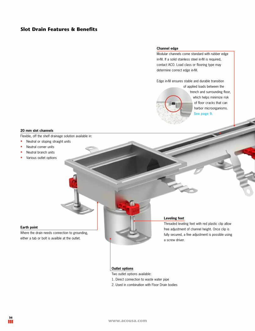
Slot Drain Features & Benefits
20 mm slot channels
Flexible, off the shelf drainage solution available in:
�Neutral or sloping straight units
�Neutral corner units
�Neutral branch units
�Various outlet options
Leveling feet
Threaded leveling feet with red plastic clip allow
free adjustment of channel height. Once clip is
fully secured, a fine adjustment is possible using
a screw driver.
Outlet options
Two outlet options available:
1. Direct connection to waste water pipe
2. Used in combination with Floor Drain bodies
Channel edge
Modular channels come standard with rubber edge
in-fill. If a solid stainless steel in-fill is required,
contact ACO. Load class or flooring type may
determine correct edge in-fill.
Edge in-fill ensures stable and durable transition
of applied loads between the
trench and surrounding floor,
which helps minimize risk
of floor cracks that can
harbor microorganisms.
See page 9.
Earth point
Where the drain needs connection to grounding,
either a tab or bolt is availble at the outlet.

37
ACO STAINLESS TRENCH
www.acousa.com
Material
The properties of stainless steel, such as corrosion resistance, non-
magnetic (see note page 4), durable and smooth (easy to clean/hygienic),
makes it the most suitable material for use in waste water applications.
In a high saline environment or in applications where a higher chemical
resistance is required, ACO recommends using grade 316L stainless steel.
Pickled & passivated
ACO stainless steel channels are pickled & passivated
to restore corrosion resistance and optimum durability.
Accessories
ACO Modular channels come
complete with gasket seal and
connecting hardware.
V-bottom channel profile
Offers enhanced flow efficiency at
low flow rates and improved self
cleaning performance.
Building codes in North America do not encourage the use of removable foul air traps in Floor Drains. Generally a 'P' trap in the pipework directly below the floor drain acts as a foul air trap. There may be specific instances where a removable foul air trap is desired, such as restricted depth installations, client-specific requirements, marine (ships & boats) etc.
The ACO foul air trap is fully removable and is available as an optional accessory to floor drain bodies. It is available in grade 304 or 316L stainless steel. The foul air trap prevents foul air from the connected drain and sewer from entering the building. A standard foul air trap support must be ordered with the foul air trap.
Information about Removable Foul Air Trap
Trap body
Support ring
Spacer bar
Spacer bar to maintain consistent
slot width and prevents channel
collapse

www.acousa.com38
Neutral Invert Channel
Slot Drain Parts Tables
Lengthin (mm)
Invertin (mm)
Part #
AISI 304 AISI 316L
19.69 (500)
2.76 (70) 92300 92350
3.54 (90) 92301 92351
4.72 (120) 92302 92352
39.37 (1000)
2.76 (70) 92305 92355
3.54 (90) 92306 92356
4.72 (120) 92307 92357
78.74 (2000)
2.76 (70) 92310 92360
3.54 (90) 92311 92361
4.72 (120) 92312 92362
118.11 (3000)
2.76 (70) 92316 92366
3.54 (90) 92317 92367
4.72 (120) 92318 92368
Lengthin (mm)
Slope%
Invert 1in (mm)
Invert 2in (mm)
Part #
AISI 304 AISI 316L
19.69 (500) 1.02.76 (70) 2.95 (75) 92303 92353
2.95 (75) 3.15 (80) 92304 92354
39.37 (1000) 0.52.76 (70) 2.95 (75) 92308 92358
2.95 (75) 3.15 (80) 92309 92359
78.74 (2000) 0.5
2.76 (70) 3.15 (80) 92313 92363
3.15 (80) 3.54 (90) 92314 92364
3.54 (90) 3.94 (100) 92315 92365
118.11 (3000) 0.33
2.76 (70) 3.15 (80) 92319 92369
3.15 (80) 3.54 (90) 92320 92370
3.54 (90) 3.94 (100) 92321 92371
3.94 (100) 4.33 (110) 92322 92372
4.33 (110) 4.72 (120) 92323 92373
Sloping Invert Channel
Corner Channel Length 1in (mm)
Length 2in (mm)
Invertin (mm)
Part #
AISI 304 AISI 316L
19.69 (500) 19.69 (500)
2.76 (70) 92338 92388
2.95 (75) 92339 92389
3.15 (80) 92340 92390
3.54 (90) 92341 92391
3.94 (100) 92342 92392
4.33 (110) 92343 92393
4.72 (120) 92344 92394
Length
Inve
rtLe
ngth
2
Length 1
Length
Inve
rt 1
Inve
rt 2
A
B
A
Notes: Channels supplied with gasket and hardware to suit deeper end of unit.
39
ACO STAINLESS TRENCH
www.acousa.com
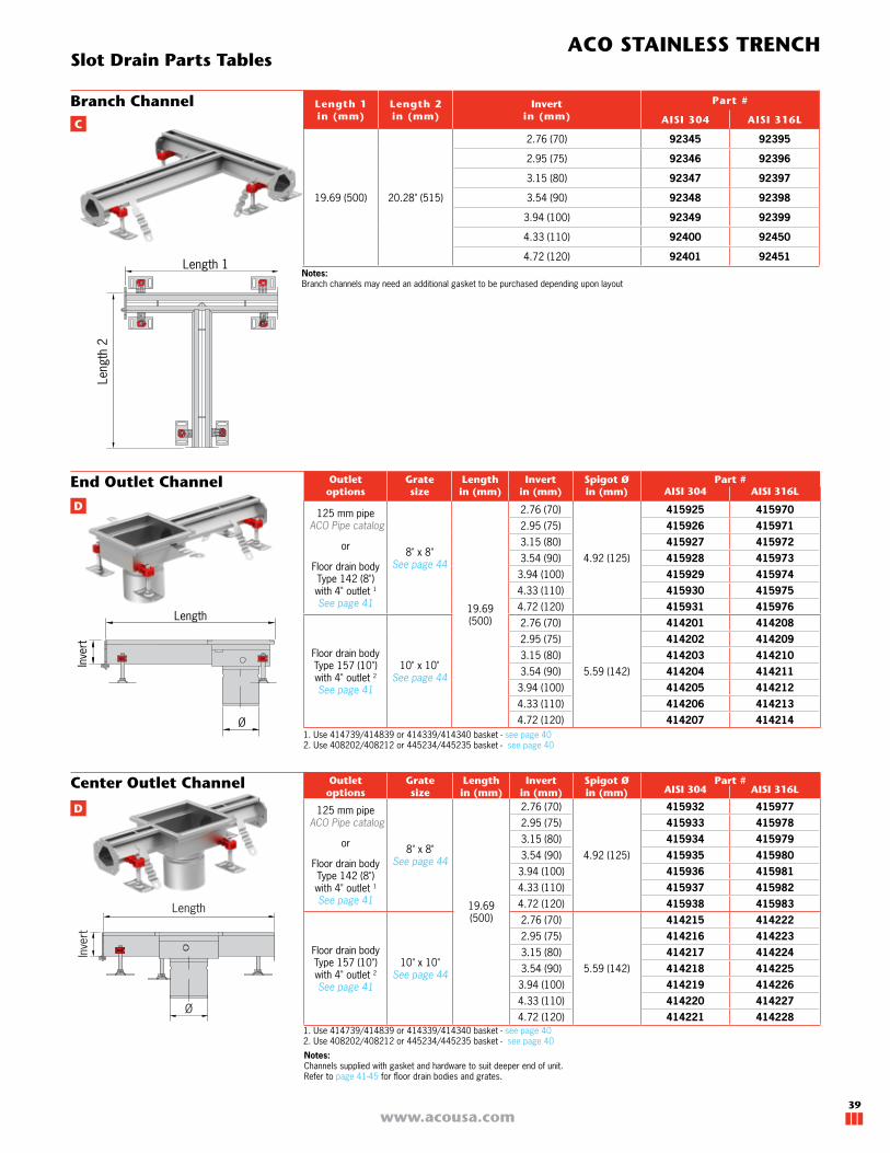
Branch Channel Length 1in (mm)
Length 2in (mm)
Invertin (mm)
Part #
AISI 304 AISI 316L
19.69 (500) 20.28" (515)
2.76 (70) 92345 92395
2.95 (75) 92346 92396
3.15 (80) 92347 92397
3.54 (90) 92348 92398
3.94 (100) 92349 92399
4.33 (110) 92400 92450
4.72 (120) 92401 92451
Outlet options
Grate size
Lengthin (mm)
Invert in (mm)
Spigot Øin (mm)
Part #AISI 304 AISI 316L
125 mm pipe ACO Pipe catalog
or
Floor drain body Type 142 (8") with 4" outlet 1
See page 41
8" x 8"See page 44
19.69 (500)
2.76 (70)
4.92 (125)
415925 4159702.95 (75) 415926 4159713.15 (80) 415927 4159723.54 (90) 415928 415973
3.94 (100) 415929 4159744.33 (110) 415930 4159754.72 (120) 415931 415976
Floor drain body Type 157 (10") with 4" outlet 2
See page 41
10" x 10"See page 44
2.76 (70)
5.59 (142)
414201 4142082.95 (75) 414202 4142093.15 (80) 414203 4142103.54 (90) 414204 414211
3.94 (100) 414205 4142124.33 (110) 414206 4142134.72 (120) 414207 414214
End Outlet Channel
Outlet options
Grate size
Lengthin (mm)
Invert in (mm)
Spigot Øin (mm)
Part #AISI 304 AISI 316L
125 mm pipe ACO Pipe catalog
or
Floor drain body Type 142 (8") with 4" outlet 1
See page 41
8" x 8"See page 44
19.69 (500)
2.76 (70)
4.92 (125)
415932 4159772.95 (75) 415933 4159783.15 (80) 415934 4159793.54 (90) 415935 4159803.94 (100) 415936 4159814.33 (110) 415937 4159824.72 (120) 415938 415983
Floor drain body Type 157 (10") with 4" outlet 2
See page 41
10" x 10"See page 44
2.76 (70)
5.59 (142)
414215 4142222.95 (75) 414216 4142233.15 (80) 414217 4142243.54 (90) 414218 4142253.94 (100) 414219 4142264.33 (110) 414220 4142274.72 (120) 414221 414228
Slot Drain Parts Tables
Leng
th 2
Length 1
Ø
Inve
rt
Length
D
C
D
Notes: Channels supplied with gasket and hardware to suit deeper end of unit.Refer to page 41-45 for floor drain bodies and grates.
1. Use 414739/414839 or 414339/414340 basket - see page 402. Use 408202/408212 or 445234/445235 basket - see page 40
1. Use 414739/414839 or 414339/414340 basket - see page 402. Use 408202/408212 or 445234/445235 basket - see page 40
Notes: Branch channels may need an additional gasket to be purchased depending upon layout
Ø
Inve
rt
Length
Center Outlet Channel
www.acousa.com40
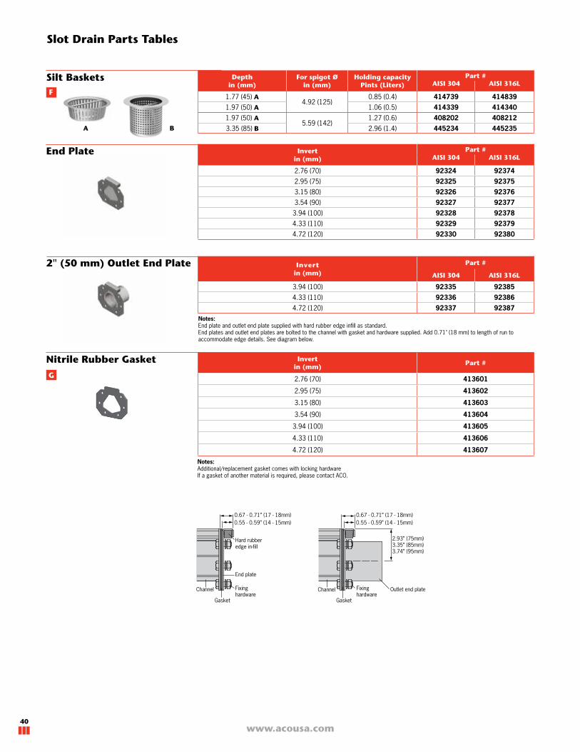
Notes: Additional/replacement gasket comes with locking hardwareIf a gasket of another material is required, please contact ACO.
Slot Drain Parts Tables
Depthin (mm)
For spigot Øin (mm)
Holding capacityPints (Liters)
Part #AISI 304 AISI 316L
1.77 (45) A4.92 (125)
0.85 (0.4) 414739 4148391.97 (50) A 1.06 (0.5) 414339 4143401.97 (50) A
5.59 (142)1.27 (0.6) 408202 408212
3.35 (85) B 2.96 (1.4) 445234 445235
Silt Baskets
Invertin (mm)
Part #AISI 304 AISI 316L
2.76 (70) 92324 923742.95 (75) 92325 923753.15 (80) 92326 923763.54 (90) 92327 923773.94 (100) 92328 923784.33 (110) 92329 923794.72 (120) 92330 92380
End Plate
Invertin (mm)
Part #
AISI 304 AISI 316L
3.94 (100) 92335 923854.33 (110) 92336 923864.72 (120) 92337 92387
2" (50 mm) Outlet End Plate
Invertin (mm)
Part #
2.76 (70) 413601
2.95 (75) 413602
3.15 (80) 413603
3.54 (90) 413604
3.94 (100) 413605
4.33 (110) 413606
4.72 (120) 413607
Nitrile Rubber Gasket
A B
Notes: End plate and outlet end plate supplied with hard rubber edge infill as standard.End plates and outlet end plates are bolted to the channel with gasket and hardware supplied. Add 0.71" (18 mm) to length of run to accommodate edge details. See diagram below.
0.55 - 0.59” (14 - 15mm)0.67 - 0.71” (17 - 18mm)
0.55 - 0.59” (14 - 15mm)
Channel
Gasket
End plate
Hard rubberedge in-fill
Fixinghardware
Channel
Gasket
Outlet end plateFixinghardware
0.67 - 0.71” (17 - 18mm)
2.93” (75mm)3.35” (85mm)3.74” (95mm)
F
G

41
ACO STAINLESS TRENCH
www.acousa.com
Floor Drain Bodies & Grates
www.acousa.com41

www.acousa.com42
Floor Drain Bodies Parts Tables
ACO stainless steel trench drains can be
connected to underground pipework by the
following ways:
1. Vertical pipe spigot out of channel bottom.
Simplest method to connect pipework.
The connection can be made with a no-hub
connector, or ACO stainless steel push fit
pipe system. This system usually requires
drain and pipework to be set up prior to
concrete/floor being poured.
2. Use of a floor drain body with location
flange. The floor drain body can be cast
into the slab at the first concrete pour. The
trench system is then set to finished height.
The vertical spigot on the underside of the
stainless steel trench will push-fit into the
floor drain body. This gives variable height
adjustment of approximately 1.4" (35 mm)
vertically.
3. Use of a floor drain body with mechanical
clamping flange. If the floor slab has a
waterproof membrane, the membrane can
be dressed into the floor drain body and
the trench system installed afterwards. As
with the location flange body, the vertical
spigot on the underside of the stainless
steel trench will push-fit into the floor drain
body. This gives variable height adjustment
of approximately 1.4" (35 mm) vertically.
Outlet Options
ACO mechanical clamping flangeFloor Drain body
Transition coupler/push-fit connection
Sch 10 pipe
End outlet channel
Membrane(by others)
End outlet channel
ACO location flangeFloor Drain body
End outlet channel
Varies up to1.4” (35mm)
depending on size
Varies up to1.4” (35mm)
dependingon size
Friction Ring
When using adjustable height floor drain with location flange, red sealing 'o' ring must be used to prevent water from entering body.
When using adjustable height floor drain with mechanical membrane clamping flange, red sealing 'o' ring must be removed to allow water to enter floor drain body through weep holes on friction ring.

43
ACO STAINLESS TRENCH
www.acousa.com
Foul air trap support ring (required when ordering foul air trap)
Foul air trap
Part Used withPart #
AISI 304 AISI 316L
Foul air trap support ring8" Floor Drain Body
(NBR) 414743
Foul air trap 414741 414841
Foul air trap support ring10" Floor Drain Body
(NBR) 408201
Foul air trap 408200 408210
Foul air trap support ring12" Floor Drain Body
(NBR) 408221
Foul air trap 408220 408230
Optional Removable Foul Air Trap
Building codes in North America do not encourage the use of removable foul air traps in Floor Drains. However, a removable foul air trap may be required due to restricted depth installations, client-specific requirements, marine (ships & boats) and others.
Body Size
Fits Spigot Øin (mm)
Flange TypeOutlet Øin (mm)
Part #
AISI 304 AISI 316L
8" 4.92 (125)
mechanical membrane clamp
4.49 (114) - 4" Sch 10 445256 445292
10" 5.59 (142) 4.49 (114) - 4" Sch 10 445133 445199
12" 7.87 (200)4.49 (114) - 4" Sch 10 445139 445205
6.61 (168) - 6" Sch 10 445145 445211
Mechanical Membrane ClampVertical Outlet
Body Size
Fits Spigot Øin (mm)
Flange TypeOutlet Øin (mm)
Part #
AISI 304 AISI 316L
8" 4.92 (125)mechanical
membrane clamp
4.49 (114) - 4" Sch 10 445268 445304
10" 5.59 (142) 4.49 (114) - 4" Sch 10 445157 445223
12" 7.87 (200) 4.49 (114) - 4" Sch 10 445163 445229
Mechanical Membrane ClampHorizontal Outlet
Body Size
Fits Spigot Øin (mm)
Flange TypeOutlet Øin (mm)
Part #
AISI 304 AISI 316L
8" 4.92 (125)
location
4.49 (114) - 4" Sch 10 445252 445288
10" 5.59 (142) 4.49 (114) - 4" Sch 10 445129 445195
12" 7.87 (200)4.49 (114) - 4" Sch 10 445135 445201
6.61 (168) - 6" Sch 10 445141 445207
Location FlangeVertical Outlet
Body Size
Fits Spigot Øin (mm)
Flange TypeOutlet Øin (mm)
Part #
AISI 304 AISI 316L
8" 4.92 (125)
location
4.49 (114) - 4" Sch 10 445264 445300
10" 5.59 (142) 4.49 (114) - 4" Sch 10 445153 445219
12" 7.87 (200) 4.49 (114) - 4" Sch 10 445159 445225
Location Flange Horizontal Outlet
Parts Table: Floor Drain Bodies
Note - an automatic trap primer can be installed to the floor drain body to prevent the 'P' trap from drying out.
Contact ACO for details.
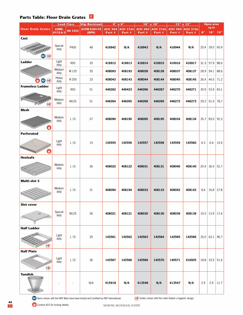
www.acousa.com44
Parts Table: Floor Drain Grates
Items shown with the NSF Mark have been tested and Certified by NSF International. Grates shown with this mark feature a hygienic design.
E
Contact ACO for locking details.
Floor Drain Grates
Load Class Slip Resistant 8” x 8” 10” x 10” 12” x 12” Open areasq in
ASME:A112.6.3
EN 1253ASTM E303-93
(BPN)AISI 304Part #
AISI 316LPart #
AISI 304Part #
AISI 316LPart #
AISI 304Part #
AISI 316LPart # 8” 10” 12”
Cast
Special duty P400 48 416942 N/A 416943 N/A 416944 N/A 20.4 39.0 60.9
Ladder Light duty R50 35 416912 416913 416914 416915 416916 416917 31.3 57.9 88.6
Medium duty M 125 35 408093 408193 408028 408128 408037 408137 28.9 54.1 88.6
Heavy duty N 250 33 408043 408143 408044 408144 408045 408145 26.4 44.5 71.2
Frameless Ladder Light duty R50 51 446262 446423 446266 446267 446270 446271 30.9 53.9 83.1
Medium duty M125 51 446264 446265 446268 446269 446272 446273 29.2 51.0 78.7
Mesh
Medium duty L 15 57 408090 408190 408095 408195 408034 408134 35.7 83.0 92.3
Perforated
Light duty L 15 15 142555 142556 142557 142558 142559 142560 4.3 6.4 10.4
Heelsafe
Medium duty L 15 36 408022 408122 408031 408131 408040 408140 20.4 36.5 52.7
Multi-slot 5
Medium duty L 15 31 408094 408194 408033 408133 408042 408142 8.6 16.8 27.8
Slot cover
Special duty M125 36 408021 408121 408030 408130 408039 408139 10.5 13.9 17.4
Half Ladder
Light duty L 15 35 142561 142562 142563 142564 142565 142566 35.0 63.1 96.7
Half Plate
Light duty L 15 36 142567 142568 142569 142570 140571 416925 18.8 33.5 51.6
Tundish
- - N/A 415918 N/A 413546 N/A 413547 N/A 2.9 2.9 11.7
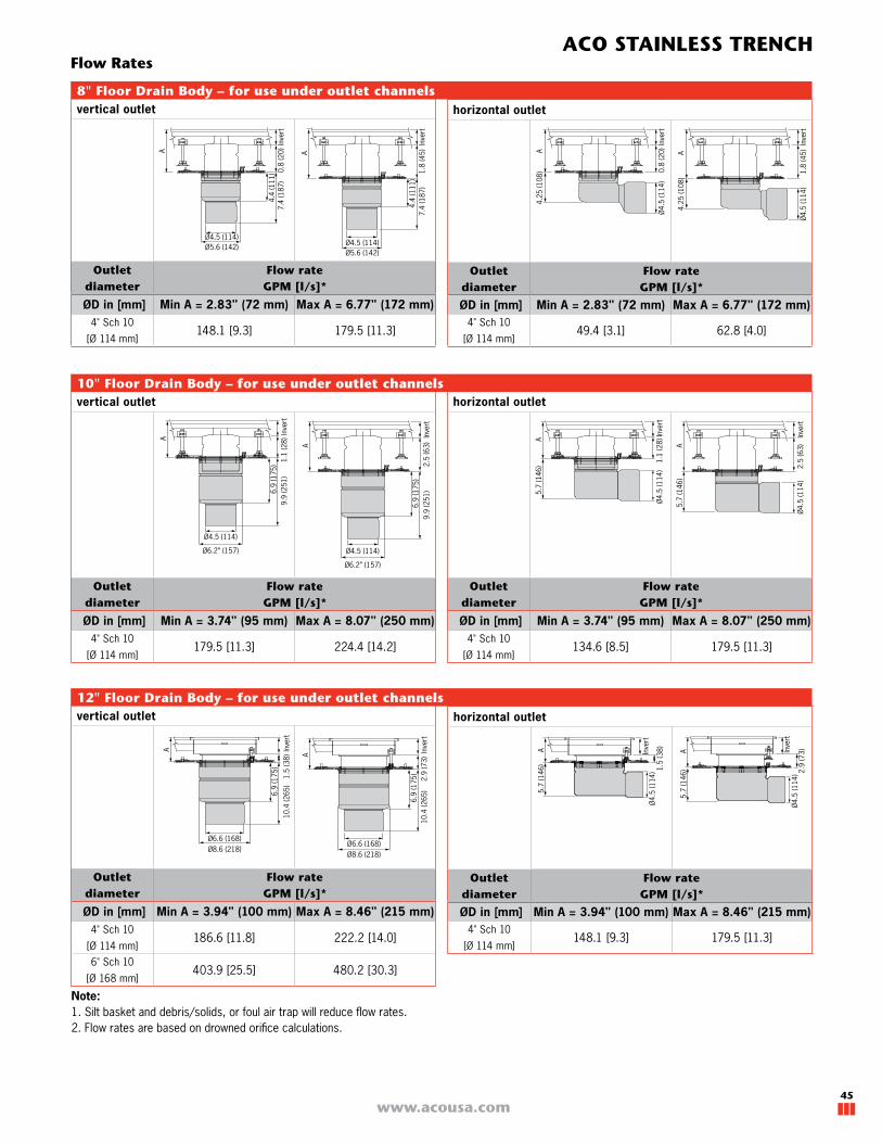
45
ACO STAINLESS TRENCH
www.acousa.com
vertical outlet
Outlet diameter
Flow rate GPM [l/s]*
ØD in [mm] Min A = 2.83" (72 mm) Max A = 6.77" (172 mm)4" Sch 10
[Ø 114 mm]148.1 [9.3] 179.5 [11.3]
Note:1. Silt basket and debris/solids, or foul air trap will reduce flow rates. 2. Flow rates are based on drowned orifice calculations.
horizontal outlet
Outlet diameter
Flow rate GPM [l/s]*
ØD in [mm] Min A = 2.83" (72 mm) Max A = 6.77" (172 mm)4" Sch 10
[Ø 114 mm]49.4 [3.1] 62.8 [4.0]
8" Floor Drain Body – for use under outlet channels
vertical outlet
Outlet diameter
Flow rate GPM [l/s]*
ØD in [mm] Min A = 3.74" (95 mm) Max A = 8.07" (250 mm)4" Sch 10
[Ø 114 mm]179.5 [11.3] 224.4 [14.2]
10" Floor Drain Body – for use under outlet channels
vertical outlet
Outlet diameter
Flow rate GPM [l/s]*
ØD in [mm] Min A = 3.94" (100 mm) Max A = 8.46" (215 mm)4" Sch 10
[Ø 114 mm]186.6 [11.8] 222.2 [14.0]
6" Sch 10
[Ø 168 mm]403.9 [25.5] 480.2 [30.3]
horizontal outlet
Outlet diameter
Flow rate GPM [l/s]*
ØD in [mm] Min A = 3.94" (100 mm) Max A = 8.46" (215 mm)4" Sch 10
[Ø 114 mm]148.1 [9.3] 179.5 [11.3]
12" Floor Drain Body – for use under outlet channels
horizontal outlet
Outlet diameter
Flow rate GPM [l/s]*
ØD in [mm] Min A = 3.74" (95 mm) Max A = 8.07" (250 mm)4" Sch 10
[Ø 114 mm]134.6 [8.5] 179.5 [11.3]
A
1.8
(45)
4.4
(111
)7.
4 (1
87)
Ø4.5 (114)Ø5.6 (142)
Inve
rt
4.4
(111
)7.
4 (1
87)
Ø4.5 (114)
0.8
(20)
Inve
rt
Ø5.6 (142)
A A
Inve
rt
4.25
(108
)
Ø4.
5 (1
14)
0.8
(20) A
Inve
rt
4.25
(108
)
Ø4.
5 (1
14)
1.8
(45)
A
6.9
(175
)9.
9 (2
51)
Ø4.5 (114)
1.1
(28)
Inve
rt
Ø6.2” (157)
A
2.5
(63)
Inve
rt6.
9 (1
75)
9.9
(251
)
Ø4.5 (114)
Ø6.2” (157)
1.1
(28)A
5.7
(146
)
Inve
rtØ
4.5
(114
)
A
Inve
rt
5.7
(146
)
Ø4.
5 (1
14)
2.5
(63)
A Inve
rtØ
4.5
(114
) 1.5
(38)
5.7
(146
)
A Inve
rtØ
4.5
(114
)
5.7
(146
) 2.9
(73)A In
vert
2.9
(73)
Ø6.6 (168)Ø8.6 (218)
6.9
(175
)10
.4 (2
65)
1.5
(38)
Inve
rt
Ø6.6 (168)Ø8.6 (218)
A
6.9
(175
)
10.4
(265
)
Flow Rates

www.acousa.com46
Custom Drain Solutions
www.acousa.com46

47
ACO STAINLESS TRENCH
www.acousa.com
Full Custom Solutions
Even unusual requirements can be solved
using stainless steel. The broad spectrum of
finishes and shapes gives complete design
freedom.
Typical non-standard stainless steel
drainage can include custom widths, special
grates, curved channels and unique depth
configurations. ACO has years of experience
with these types of applications, and in
instances where a standard or modified
standard product cannot fulfil the project,
please contact us.
Customers’ individual project designs can be
managed by our expert team with tailored
services for specific projects, including
complete technical support, CAD layout
drawings and assembly instructions.
Contact our Sales/Technical department team
to help find the best solution.
Fully customized channels can include:
�Radius channels and grates
�Custom widths
�Custom depths
�Custom base profile
�Custom edge profile
�Built-in back splash upstand
�Custom configurations of channel layout
�Different invert bottom configurations
�Maximum single piece of 18' (5.5m)
�Different gauge of material for channels
�End profile - overlap end flange
Channel Profile Ideas
Splash Back - Helps contain water into
the channel.
Folded Edge - Provides a discrete edge
detail.
Half Round - Easy clean as fewer corners
for debris to accumulate. Center toe-bar
Toe-bar for Slot 20Provides a smaller 1/4" (6.5 mm) twin slot
with 1/4" (6.5 mm) central toe-bar, while
keeping the larger drainage throat of the Slot
20 channel - perfect for ADA, Heelsafe and
bare foot applications. Custom slot width and
toe-bar width available.
Welded channel connectionFor certain installations it may be required to
weld ACO modular channels into continuous
runs. This will eliminate the 0.08-0.12" (2-3 mm)
rubber gasket at each joint and run lengths
and outlet positions need to be adjusted
accordingly. A technical bulletin is available
upon request for additional guidance.
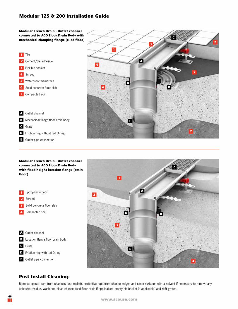
www.acousa.com48
Modular Trench Drain - Outlet channel connected to ACO Floor Drain Body with fixed height location flange (resin floor)
Epoxy/resin floor
Screed
Solid concrete floor slab
Compacted soil
Modular 125 & 200 Installation Guide
Tile
Cement/tile adhesive
Flexible sealant
Screed
Waterproof membrane
Solid concrete floor slab
Compacted soil
Post-Install Cleaning:Remove spacer bars from channels (use mallet), protective tape from channel edges and clean surfaces with a solvent if necessary to remove any
adhesive residue. Wash and clean channel (and floor drain if applicable), empty silt basket (if applicable) and refit grates.
Outlet channel
Mechanical flange floor drain body
Grate
Friction ring without red O-ring
Outlet pipe connection
Outlet channel
Location flange floor drain body
Grate
Friction ring with red O-ring
Outlet pipe connection
Modular Trench Drain - Outlet channel connected to ACO Floor Drain Body with mechanical clamping flange (tiled floor)

49
ACO STAINLESS TRENCH
www.acousa.com
ACO Slot Drain - Outlet channel connected to ACO Floor Drain Body with fixed height location flange (resin floor)
Epoxy/resin floor
Screed
Solid concrete floor slab
Compacted soil
ACO Slot Drain - Outlet channel con-nected to ACO Floor Drain Body with mechanical clamping flange (tiled floor)
Slot Drain Installation Guide
Tile
Cement/tile adhesive
Flexible sealant
Screed
Waterproof membrane
Solid concrete floor slab
Compacted soil
Post-Install Cleaning:Remove spacer bars from channels (use mallet), protective tape from channel edges and clean surfaces with a solvent if necessary to remove any
adhesive residue. Wash and clean channel (and floor drain if applicable), empty silt basket (if applicable) and refit grates.
Outlet channel - requires Floor drain grate
Mechanical flange floor drain body
Slot channel
Friction ring without red O-ring
Outlet pipe connection
Outlet channel - requires Floor drain grate
Location flange floor drain body
Slot channel
Friction ring with red O-ring
Outlet pipe connection
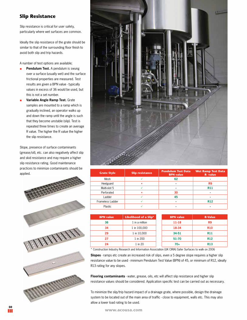
www.acousa.com50
Slip Resistance
Slip resistance is critical for user safety,
particularly where wet surfaces are common.
Ideally the slip resistance of the grate should be
similar to that of the surrounding floor finish to
avoid both slip and trip hazards.
A number of test options are available;
■ Pendulum Test. A pendulum is swung
over a surface (usually wet) and the surface
frictional properties are measured. Test
results are given a BPN value - typically
values in excess of 36 would be used, but
this is not a set number.
■ Variable Angle Ramp Test. Grate
samples are mounted to a ramp which is
gradually inclined, an operator walks up
and down the ramp until the angle is such
that they become unstable (slip). Test is
repeated three times to create an average
R value. The higher the R value the higher
the slip resistance.
Slope, presence of surface contaminants
(grease/oil), etc. can also negatively affect slip
and skid resistance and may require a higher
slip resistance rating. Good maintenance
practices to minimize contaminants should be
applied. Grate Style Slip resistancePendulum Test Data
BPN valueWet Ramp Test Data
R- value
Mesh 62 -Heelguard - R9Multi-slot 5 - R11Perforated 30 -
Ladder 45 -Frameless Ladder - R12
Plastic - -
Slopes - ramps etc create an increased risk of slips, even a 5 degree slope requires a higher slip
resistance value to be used - minimum Pendulum Test Value (BPN) of 45, or minimum of R12, ideally
R13 rating for any slopes.
Flooring contaminants - water, grease, oils, etc will affect slip resistance and higher slip
resistance values should be considered. Application specific test can be carried out as necessary.
To minimize the slip/trip hazard impact of a drainage grate, where possible, design the drainage
system to be located out of the main area of traffic - close to equipment, walls etc. This may also
allow a lower load rating to be used.
BPN value Likelihood of a Slip*
36 1 in a million
34 1 in 100,000
29 1 in 10,000
27 1 in 200
24 1 in 20
BPN value R-Value
11-18 R9
18-34 R10
34-51 R11
51-70 R12
70+ R13
* Construction Industry Research and Information Association (UK CIRIA) Safer Surfaces to walk on 2006

51
ACO STAINLESS TRENCH
www.acousa.com
Glossary
Anti-shunt lugs - device to prevent lateral grate
movement along channel length due to dynamic
traffic.
Anti-slip grate - grates certified to offer
improved grip.
Axle load - load carried by each axle of vehicle.
BPN - British Pendulum Number - a slip
resistance rating resulting from the Pendulum
test. See page 50.
Clamping flange - metal plate with mechanical
fixing (bolts) that allows a floor membrane to be
dressed into floor drain.
Electropolished - electrolytic process
producing a highly reflective luster which offers
chemical and bacterial resistance.
Earth point - either a tab or bolt is added at
the outlet to accept a grounding wire.
Floor edge - channel edge option that allows
floor material to be isolated from channel. See
page 9.
Flow rate - quantity of liquid evacuated through
outlet in a given time frame - gallons per minute
(GPM).
Foul air trap - shaped pipe section to prevent
odors traveling up from underground waste
water system. ACO also offer an inline option.
Gasket - flexible, non-absorbent seal between
connecting components. Supplied in neoprene
material as standard - viton and nitrile options
available - Call ACO for details.
Heelsafe - per ASME A112.6 - maximum grate
hole size in least dimension of 0.31", deemed
safe for high-heeled shoes.
Invert depth - depth from top of grate to inside
base of channel.
Leveling feet - fixed to base of channels to
allow height and level adjustment.
Linished - brushed effect usually on channel
edge surface.
Load class - ability of grate to resist load
specified in a load standard.
Pickled & passivated - chemical descaling
and coating of stainless steel part to restore
corrosion and chemical resistance qualities.
Point load - load exerted through a specific
area for specification and testing purposes.
'R' Value - a slip resistance rating resulting from
Variable Angle Ramp Test. See page 50.
Sieve - perforated plate to prevent sediment/
debris passing into pipework.
Silt basket - perforated basket to collect
larger volumes of sediment/debris passing into
pipework.
Spacer bars - stainless steel cross sections
tack welded in grate recess to maintain channel
width/profile during installation and handling.
Spigot - section of pipe used for outlet
connection, may require a coupler.
Splash back - custom channel edge detail for
areas where inflow liquids need to be contained.
Trap primer - an automatic trap primer can be
installed at the outlet to prevent the 'P' trap from
drying out.
Vinyl seal - channel edge option that allows
connection/sealing of vinyl sheet floor material.
See page 9.
Wheel load - load exerted through one wheel
of vehicle/trolley - not always equal to axle load
divided by number of wheels.

© May 2018 ACO, Inc.
All reasonable care has been taken in compiling the information in this document. All recommendations and suggestions on the use of ACO products are made without guarantee since the conditions of use are beyond the control of the company. It is the customer's responsibility to ensure that each product is fit for its intended purpose and that the actual conditions of use are suitable. ACO, Inc. reserves the right to change products and specifications without notice.
Re-order Part # BD017 v1.0
Other ACO products
External drainage
ACO DrainModular trench drain systems for commercial, industrial and landscape applications.
ACO Sport Surface drainage and building accessories for track & field.
ACO InfrastructureSurface drainage products engineered for highways, urban roads and bridges.
Aquaduct Custom design and manufacture of fiberglass trench drain systems.
ACO DuctLinear ducting system with removable solid covers.
ACO Environment Oil water separators and spill containment systems.
ACO Wildlife Tunnel and fence system to guide amphibians and other small creatures safely across roads.
ACO StormBrixxA unique and patented plastic geocellular storm water management system.
ACO Self Simple drainage and building components for use around the home, garden and office.
Building drainage
ACO Stainless Stainless steel trench drains.
ACO Floor Drain Stainless steel floor drains.
ACO BuildLineDrainage products for thresholds, balconies, green roofs and building façades.
ACO Pipe Stainless steel push-fit pipe system.
ACO ShowerDrainShower drainage.
QuARTzDesigner bathroom floor solutions.
ACO, Inc.
West Sales Office Northeast Sales Office Southeast Sales Office825 W. Beechcraft St. 9470 Pinecone Drive 4211 Pleasant RoadCasa Grande, AZ 85122 Mentor, OH 44060 Fort Mill, SC 29708Tel: (520) 421-9988 Tel: (440) 639-7230 Toll Free: (800) 543-4764Toll Free: (888) 490-9552 Toll Free: (800) 543-4764 Fax: (803) 802-1063Fax: (520) 421-9899 Fax: (440) 639-7235 Electronic Contact: [email protected] www.acousa.com