
ACKNOWLEGEMENT - Near East Universitydocs.neu.edu.tr/library/6346146321.docx · Web viewNEAR EAST...
57
NEAR EAST UNIVERSITY FACULTY OF ENGINEERING ELECTRICAL POWERED WHEELCHAIR Hasan Ozkan 20123742 Osman Galal 20110069 Alper Youssouf 20100222 Ramin Malikov 20102579 Graduation Project Thesis i
Transcript of ACKNOWLEGEMENT - Near East Universitydocs.neu.edu.tr/library/6346146321.docx · Web viewNEAR EAST...
NEAR EAST UNIVERSITY
FACULTY OF ENGINEERING
ELECTRICAL POWERED WHEELCHAIR
Hasan Ozkan 20123742
Osman Galal 20110069
Alper Youssouf 20100222
Ramin Malikov 20102579
Graduation Project Thesis
Department Of Biomedical Engineering
Nicosia 2014
i
The undersigned, appointed by the dean of the Graduate School, have examined the entitled
ELECTRICAL POWERED WHEELCHAIR
presented by HASAN OZKAN,OSMAN GALAL,ALPER YUSUF,RAMİN MALİKOV
a candidate for the degree of Biomedical Engineering.
and hereby certify that, in their opinion, it is worthy of acceptance.
Professor Doç Dr.Terin Adalı
ii
Academic Thesis: Declaration Of Authorship
We,Hasan Ozkan,Alper Yusuf,Osman Galal and Ramin Malikov
declare that this thesis and the work presented in it are my own and has been generated by me as the result of my
own original research.
Electical Powered Wheelchair.
I confirm that:
1. This work was done wholly or mainly while in candidature for a research degree at this University;
2. Where any part of this thesis has previously been submitted for a degree or any other qualification at this
University or any other institution, this has been clearly stated;
3. Where I have consulted the published work of others, this is always clearly attributed;
4. Where I have quoted from the work of others, the source is always given. With the exception of such
quotations, this thesis is entirely my own work;
5. I have acknowledged all main sources of help;
6. Where the thesis is based on work done by myself jointly with others, I have made clear exactly what was
done by others and what I have contributed myself;
Signed:
………………………………………………………………………………………………………………………
Date: ………………………………………………………………………………………………………………………….
iii

ACKNOWLEGEMENT
Firstly, we would like to thank our department chairman Assoc. Prof. Dr. Terin Adalı, and special thanks to our
friend Ramin Malikov for his all advices, supporting and belief in us and our works. He allowed us to regain
our self-confidence every time that we though to give up during the preparation of this Project, and thanks to our
co-supervisors Serife Kaba and Buse Ugur for their supporting.
Second, we have to thank to our families, material or moral, for each support and their constant encouragement
during the preparation of our Project.
Finally, we would like to thank all of our friends, they helped us with them advices and supports.
iv

ABSTRACT
A electric powered wheelchair is a medical device which is powered by electrical sources in order to help disabled people to
move the chair without using any mechanical force. This device will provide movement of disabled people..We have used a
PC mouse in order to control a wheelchair. This will help disabled people to move without using their arms or another
peoples’ help.Sometimes disabled people can only move their hands but not their arms so this is the main reason why we
have used a PC mouse to control the wheelchair.
v
LIST OF CONTENTS
ACKNOWLEGEMENT.............................................................................................................................. iv
ABSTRACT...............................................................................................................................................v
LIST OF ABBREVIATIONS.......................................................................................................................vii
LIST OF TABLES.....................................................................................................................................viii
LIST OF FIGURES..................................................................................................................................... ix
LIST OF FIGURES.....................................................................................................................................x
HISTORY OF WHEELCHAIR......................................................................................................................1
The Bath Wheelchair......................................................................................................................1
Late 1800s......................................................................................................................................1
The 1900s.......................................................................................................................................1
The Folding Wheelchair..........................................................................................................................1
First Motorized Wheelchair - Electric Wheelchair..................................................................................1
MANUFACTURERS AND EXAMPLES OF WHEELCHAIR............................................................................3
MANUFACTURERS AND EXAMPLES OF WHEELCHAIR............................................................................4
MATERIALS WE HAVE USED...................................................................................................................5
MATERIALS WE HAVE USED...................................................................................................................6
Relay...............................................................................................................................................6
Time delay relay.............................................................................................................................6
Leds................................................................................................................................................8
Dc Motor......................................................................................................................................10
Digital Voltmeter..........................................................................................................................13
BUILDING PROCESS..............................................................................................................................19
MOVEMENT MECHANISM....................................................................................................................27
Straight.........................................................................................................................................27
Turning Principle...........................................................................................................................27
Stopping Principle.........................................................................................................................27
DIFFUCULTIES DURING CONSTRUCTION..............................................................................................28
ADVANTAGES.......................................................................................................................................29
DISADVANTAGES..................................................................................................................................31
CURRENT DEVICES................................................................................................................................32
FUTURE IMPROVEMENTS.....................................................................................................................35
REFERENCES.........................................................................................................................................36
vi
LIST OF ABBREVIATIONS
Ohm(Ω): Unitofelectricalresistance.
V: Voltage
C: Current
W: Watt
BPM: Beat Per Minute
Sec(S): Second
mS: Millisecond
µ: Micro
m:Milli
k: Kilo
Hz: Hertz
Mm: millimeter
vii
LIST OF TABLES
Table 1 ……………………………………………………………………………………Catagories Of
Wheelchairs
Table 2………………………………………………………………………………….. Manufacturers And
Models
viii
LIST OF FIGURESFigure 1 ……………………………………………………………………………………………………………Relay
Figure 2 ………………………………………………………………………………………..Time Delay Relay
Figure 3 ……………………………………………………………………………………………………………..LED
Figure 4 ……………………………………………………………………………………………………………..LED
Figure 5 ……………………………………………………………………………………………………………..LED
Figure 6 ……………………………………………………………………………………………………DC-motor
Figure 7 ……………………………………………………………………………………………………….Battery
Figure 8………………………………………………………………………………………. Voltmeter Circuit
Figure 9 ……………………………………………………………………………………………………Voltmeter
Figure 10 ……………………………………………………………………………………………………..Wheels
Figure 11 ……………………………………………………………………………………………………..Wheels
Figure 12 ……………………………………………………………………………………………Front Wheels
Figure 13 ………………………………………………………………………………………………………….Horn
Figure 14 ……………………………………………………………………………………………..Wheel Chair
Figure 15 ……………………………………………………………………………………….Building Process
Figure 16 ………………………………………………………………………………………..Building Process
Figure 17 …………………………………………………………………………………………Building Process
Figure 18 …………………………………………………………………………………………Building Process
Figure 19 …………………………………………………………………………………………Building Process
ix

LIST OF FIGURESFigure 20 ……………………………………………………………………………………………………...Building Process
Figure 21………………………………………………………………………………………………………. Building Process
Figure 22 ……………………………………………………………………………………………………….…...Final
Product
Figure 23 …………………………………………………………………………………………………………….Circuit
Design
Figure 24 ……………………………………………………………………………………………………….Welding
Machine
Figure 25 ……………………………………………………………………………………………………………..Lirrus Plus
HD
Figure 26…………………………………………………………………………………………………. .Compact Mid-Wheel
Figure 27 ………………………………………………………………………………………..Compass Sportmedalist P22
Figure 28 ………………………………………………………………………………………..Compass Sportmedalist P23
Figure 29 …………………………………………………………………………………………………………..Predi Jazzy
Elite
Figure 30 …………………………………………………………………………………………………………..Travel Price
300
Figure 31………………………………………………………………………………………………………………….
Prontom51
Figure 32 ………………………………………………………………………………………………..Cirrus Plus Wheelchair
Figure 33 ……………………………………………………………………Quickie XFinder Power Assist Wheelchair
Figure 34 ………………………………………………………………………………………………..Quina Wheelchair 600
x
HISTORY OF WHEELCHAIR
It is uncertain as to what can be considered the first wheelchair, or who invented it. The first known dedicated
wheelchair (invented in 1595 and called an invalids chair) was made for Phillip II of Spain by an unknown
inventor. In 1655, Stephen Farfler, a paraplegic watchmaker, built a self-propelling chair on a three wheel
chassis.
The Bath Wheelchair
In 1783, John Dawson of Bath, England, invented a wheelchair named after the town of Bath. Dawson designed
a chair with two large wheels and one small one. The Bath wheelchair outsold all other wheelchairs throughout
the early.
Late 1800s
However, the Bath wheelchair was not that comfortable and during the last half of the 19th century many
improvements were made to wheelchairs. An 1869 patent for a wheelchair showed the first model with rear push
wheels and small front casters. Between, 1867 to 1875, inventors added new hollow rubber wheels similar to
those used on bicycles on metal rims. In 1881, the pushrims for added self-propulsion were invented.
The 1900s
In 1900, the first spoked wheels were used on wheelchairs. In 1916, the first motorized wheelchair was
manufactured in London.
The Folding WheelchairIn 1932, engineer, Harry Jennings, built the first folding, tubular steel wheelchair. That was the earliest
wheelchair similar to what is in modern use today. That wheelchair was built for a paraplegic friend of Jennings
called Herbert Everest. Together they founded Everest & Jennings, a company that monopolized the wheelchair
market for many years. An antitrust suit was actually brought against Everest & Jennings by the Department of
Justice, who charged the company with rigging wheelchair prices. The case was finally settled out of court.
First Motorized Wheelchair - Electric Wheelchair
1
The first wheelchairs were self-powered, and worked by a patient turning the wheels of their chair manually. Of
course, if a patient was unable to do this, another person would have to push the wheelchair and patient from
behind. A motorized or power wheelchair is one where a small motor drives the wheels to revolve. Attempts to
invent a motorized wheelchair were made as far back as 1916, however, no successful commercial production
occurred at that time.
The first electric-powered wheelchair was invented by Canadian inventor, George Klein and his team of
engineers while working for the National Research Council of Canada in a program to assist the injured veterans
returning after World War II. George Klein also invented the microsurgical staple gun.
Everest & Jennings, the same company whose founders created the folding wheelchair were the first to
manufacture the electric wheelchair on a mass scale beginning in 1956.
2
MANUFACTURERS AND EXAMPLES OF WHEELCHAIR
Table 1
3
MANUFACTURERS AND EXAMPLES OF WHEELCHAIR
Table 2
4

MATERIALS WE HAVE USED Relay
Led Lights
12V D.C Motor (50-60) Rpm
12V 50Ah Battery
Digital Voltmeter
Astable multivibrator
Wheels
Horn
Metal Frame
5

MATERIALS WE HAVE USED
Relay
A relay is an electrically operated switch. Many relays use an electromagnet to mechanically operate a switch,
but other operating principles are also used, such as solid-state relays. Relays are used where it is necessary to
control a circuit by a low-power signal (with complete electrical isolation between control and controlled
circuits), or where several circuits must be controlled by one signal. The first relays were used in long
distance telegraph circuits as amplifiers: they repeated the signal coming in from one circuit and re-transmitted it
on another circuit. Relays were used extensively in telephone exchanges and early computers to perform logical
operations.
A type of relay that can handle the high power required to directly control an electric motor or other loads is
called a contactor. Solid-state relays control power circuits with no moving parts, instead using a semiconductor
device to perform switching.
Figure 1
6

Time delay relay
Timing relays are arranged for an intentional delay in operating their contacts. A very short (a fraction of a
second) delay would use a copper disk between the armature and moving blade assembly. Current flowing in the
disk maintains magnetic field for a short time, lengthening release time. For a slightly longer (up to a minute)
delay, a dashpot is used. A dashpot is a piston filled with fluid that is allowed to escape slowly; both air-filled
and oil-filled dashpots are used. The time period can be varied by increasing or decreasing the flow rate. For
longer time periods, a mechanical clockwork timer is installed. Relays may be arranged for a fixed timing
period, or may be field adjustable, or remotely set from a control panel. Modern microprocessor-based timing
relays provide precision timing over a great range.
The high current of the cranking motor to be controlled with small wiring and contacts in the ignition key.
Figure 2
Electromechanical switching systems including Strowger and Crossbar telephone exchanges made extensive use
of relays in ancillary control circuits. The Relay Automatic Telephone Company also manufactured telephone
exchanges based solely on relay switching techniques designed by Gotthilf Ansgarius Betulander. The first
public relay based telephone exchange in the UK was installed in Fleetwood on 15 July 1922 and remained in
service until 1959.
The use of relays for the logical control of complex switching systems like telephone exchanges was studied
by Claude Shannon, who formalized the application of Boolean algebra to relay circuit design in A Symbolic
Analysis of Relay and Switching Circuits. Relays can perform the basic operations of Boolean combinatorial
logic. For example, the boolean AND function is realised by connecting normally open relay contacts in series,
the OR function by connecting normally open contacts in parallel. Inversion of a logical input can be done with a
7
normally-closed contact. Relays were used for control of automated systemsfor machine tools and production
lines. The Ladder programming language is often used for designing relay logic networks.
Early electro-mechanical computers such as the ARRA, Harvard Mark II, Zuse Z2, and Zuse Z3 relays for logic
and working registers. However, electronic devices proved faster and easier to use.
Because relays are much more resistant than semiconductors to nuclear radiation, they are widely used in safety-
critical logic, such as the control panels of radioactive waste-handling machinery. Electromechanical protective
relays are used to detect overload and other faults on electrical lines by opening and closing circuit breakers.
Leds
A light-emitting diode (LED) is a two-lead semiconductor light source. It is a basic pn-junction diode, which
emits light when activated.[6] When a suitable voltage is applied to the leads, electrons are able to recombine
with electron holes within the device, releasing energy in the form of photons. This effect is
called electroluminescence, and the color of the light (corresponding to the energy of the photon) is determined
by the energy band gap of the semiconductor.
An LED is often small in area (less than 1 mm2) and integrated optical components may be used to shape
its radiation pattern.[7]
Appearing as practical electronic components in 1962,[8] the earliest LEDs emitted low-intensity infrared light.
Infrared LEDs are still frequently used as transmitting elements in remote-control circuits, such as those in
remote controls for a wide variety of consumer electronics. The first visible-light LEDs were also of low
intensity, and limited to red. Modern LEDs are available across the visible,ultraviolet, and infrared wavelengths,
with very high brightness.
Early LEDs were often used as indicator lamps for electronic devices, replacing small incandescent bulbs. They
were soon packaged into numeric readouts in the form of seven-segment displays, and were commonly seen in
digital clocks.
Recent developments in LEDs permit them to be used in environmental and task lighting. LEDs have many
advantages over incandescent light sources including lower energyconsumption, longer lifetime, improved
physical robustness, smaller size, and faster switching. Light-emitting diodes are now used in applications as
diverse as aviation lighting, automotive headlamps, advertising, general lighting, traffic signals, and camera
flashes. However, LEDs powerful enough for room lighting are still relatively expensive, and require more
precise current and heat management than compact fluorescent lamp sources of comparable output.
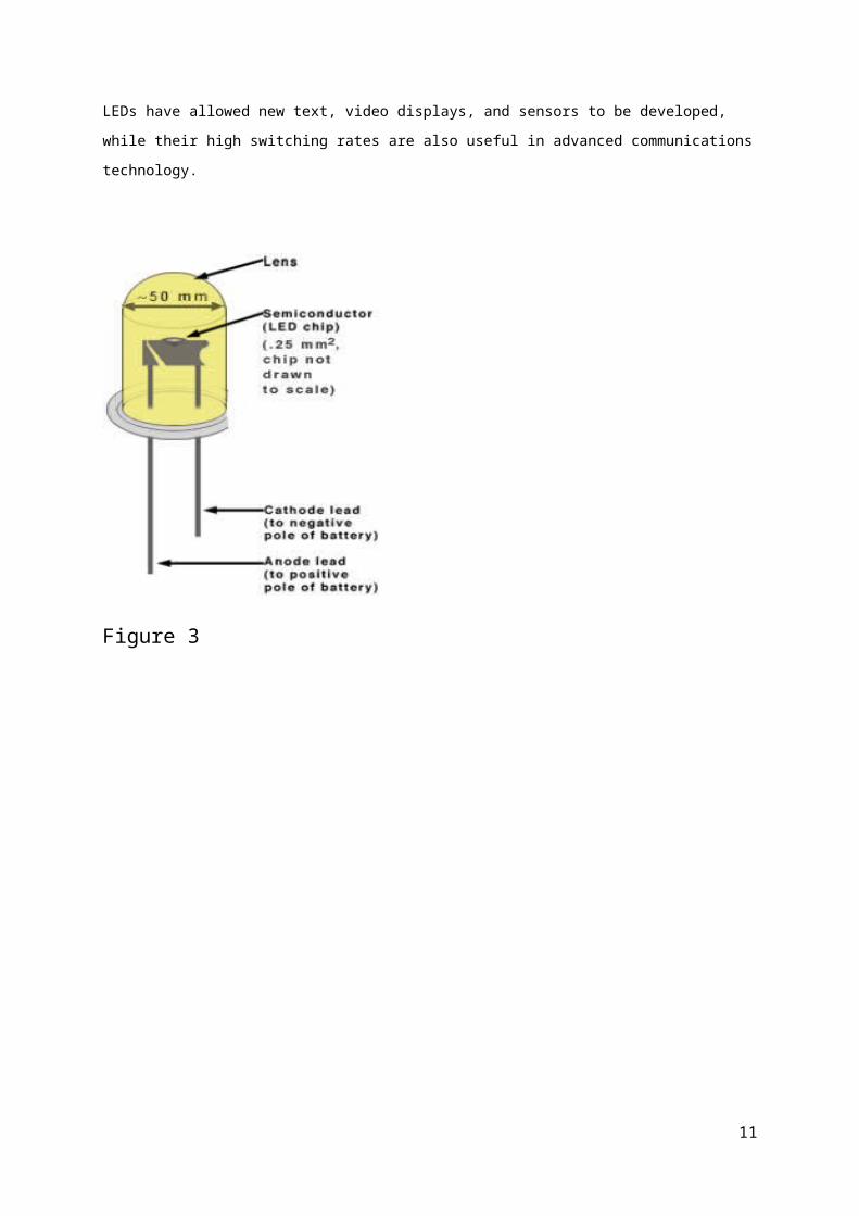
LEDs have allowed new text, video displays, and sensors to be developed, while their high switching rates are
also useful in advanced communications technology.
8
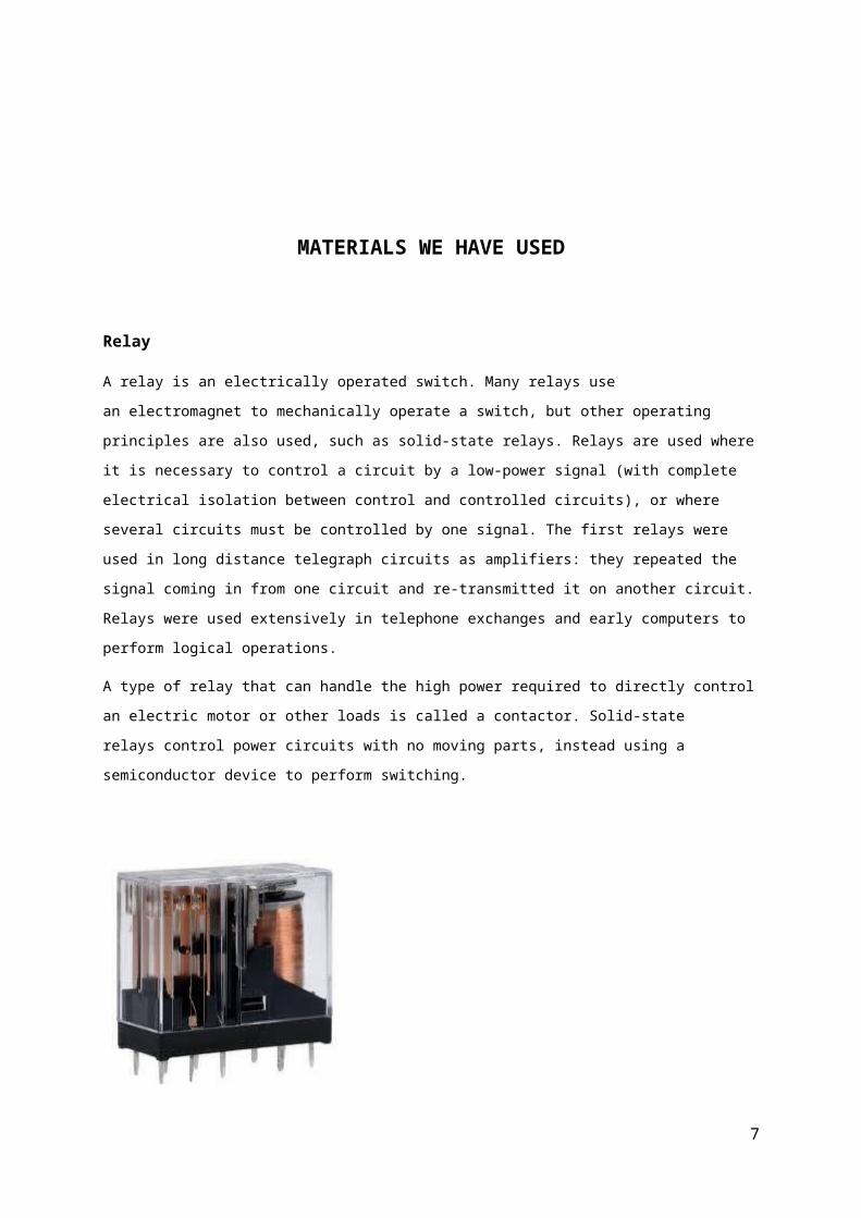
Figure 3
Figure 4
9

Figure 5
Dc Motor
A DC motor relies on the fact that like magnet poles repel and unlike magnetic poles attract each other. A coil of
wire with a current running through it generates an electromagnetic field aligned with the center of the coil. By
switching the current on or off in a coil its magnetic field can be switched on or off or by switching the direction
of the current in the coil the direction of the generated magnetic field can be switched 180°. A simple DC
motor typically has a stationary set of magnets in the stator and an armature with a series of two or more
windings of wire wrapped in insulated stack slots around iron pole pieces (called stack teeth) with the ends of the
wires terminating on a commutator. The armature includes the mounting bearings that keep it in the center of the
motor and the power shaft of the motor and the commutator connections. The winding in the armature continues
to loop all the way around the armature and uses either single or parallel conductors (wires), and can circle
several times around the stack teeth. The total amount of current sent to the coil, the coil's size and what it's
wrapped around dictate the strength of the electromagnetic field created. The sequence of turning a particular
coil on or off dictates what direction the effective electromagnetic fields are pointed. By turning on and off coils
in sequence a rotating magnetic field can be created. These rotating magnetic fields interact with the magnetic
fields of the magnets (permanent or electromagnets) in the stationary part of the motor (stator) to create a force
on the armature which causes it to rotate. In some DC motor designs the stator fields use electromagnets to
create their magnetic fields which allow greater control over the motor. At high power levels, DC motors are
almost always cooled using forced air.
The commutator allows each armature coil to be activated in turn. The current in the coil is typically supplied via
two brushes that make moving contact with the commutator. Now, some brushless DC motors have electronics
that switch the DC current to each coil on and off and have no brushes to wear out or create sparks.
10

Different number of stator and armature fields as well as how they are connected provide different inherent
speed/torque regulation characteristics. The speed of a DC motor can be controlled by changing the voltage
applied to the armature. The introduction of variable resistance in the armature circuit or field circuit allowed
speed control of dc motors.
Since the series-wound DC motor develops its highest torque at low speed, it is often used in traction
applications such as electric locomotives, and trams. The DC motor was the mainstay of electric traction
drives on both electric and diesel-electric locomotives, street-cars/trams and diesel electric drilling rigs for many
years. The introduction of DC motors and an electrical grid system to run machinery starting in the 1870s started
a new second Industrial Revolution. DC motors can operate directly from rechargeable batteries, providing the
motive power for the first electric vehicles and today's hybrid cars and electric cars as well as driving a host
of cordless tools. Today DC motors are still found in applications as small as toys and disk drives, or in large
sizes to operate steel rolling mills and paper machines.
If external power is applied to a DC motor it acts as a DC generator, a dynamo. This feature is used to slow
down and recharge batteries onhybrid car and electric cars or to return electricity back to the electric grid used on
a street car or electric powered train line when they slow down. This process is called regenerative braking on
hybrid and electric cars. In diesel electric locomotives they also use their DC motors as generators to slow down
but dissipate the energy in resistor stacks. Newer designs are adding large battery packs to recapture some of this
energy.
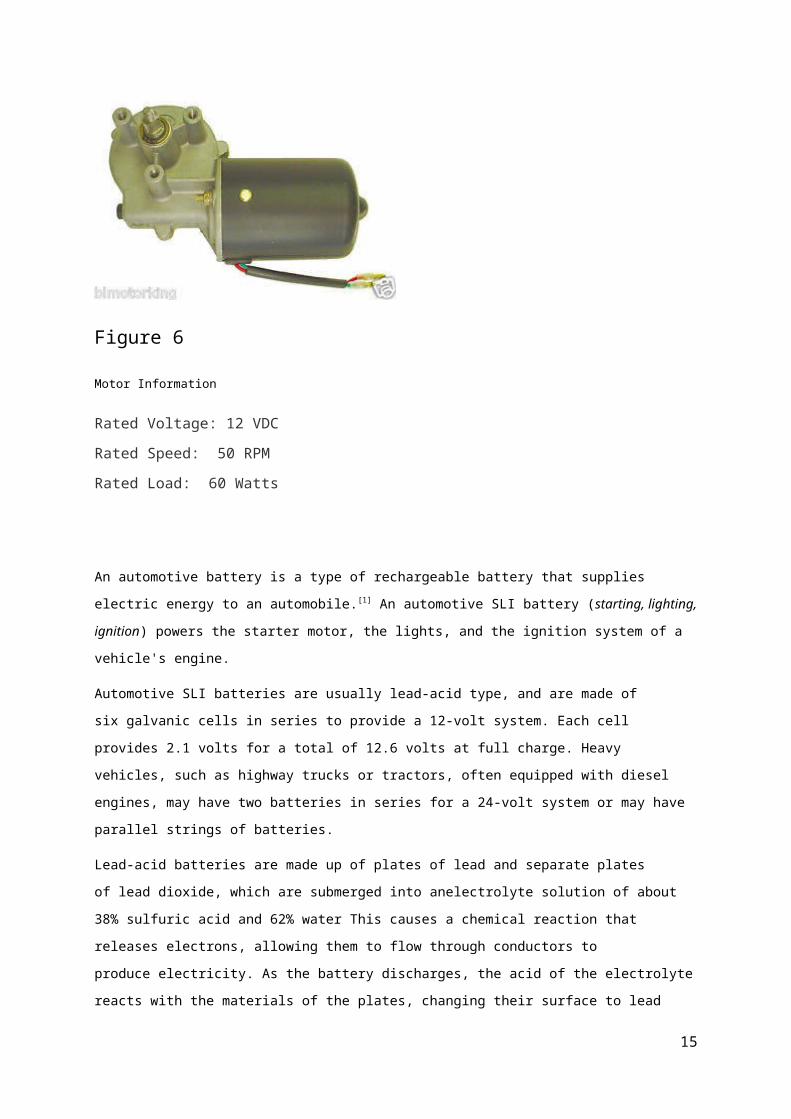
Figure 6
Motor Information
Rated Voltage: 12 VDC
Rated Speed: 50 RPM
Rated Load: 60 Watts
11

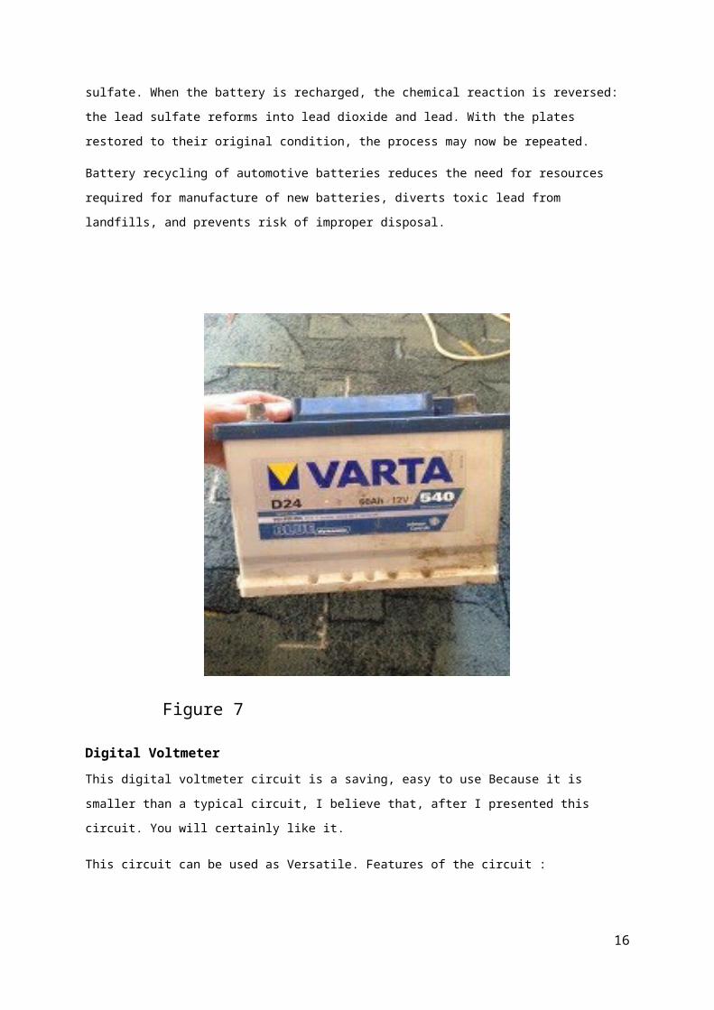
An automotive battery is a type of rechargeable battery that supplies electric energy to an automobile.[1] An
automotive SLI battery (starting, lighting, ignition) powers the starter motor, the lights, and the ignition
system of a vehicle's engine.
Automotive SLI batteries are usually lead-acid type, and are made of six galvanic cells in series to provide a 12-
volt system. Each cell provides 2.1 volts for a total of 12.6 volts at full charge. Heavy vehicles, such as highway
trucks or tractors, often equipped with diesel engines, may have two batteries in series for a 24-volt system or
may have parallel strings of batteries.
Lead-acid batteries are made up of plates of lead and separate plates of lead dioxide, which are submerged into
anelectrolyte solution of about 38% sulfuric acid and 62% water This causes a chemical reaction that
releases electrons, allowing them to flow through conductors to produce electricity. As the battery discharges,
the acid of the electrolyte reacts with the materials of the plates, changing their surface to lead sulfate. When the
battery is recharged, the chemical reaction is reversed: the lead sulfate reforms into lead dioxide and lead. With
the plates restored to their original condition, the process may now be repeated.
Battery recycling of automotive batteries reduces the need for resources required for manufacture of new
batteries, diverts toxic lead from landfills, and prevents risk of improper disposal.
Figure 7
12
Digital Voltmeter
This digital voltmeter circuit is a saving, easy to use Because it is smaller than a typical circuit, I believe that,
after I presented this circuit. You will certainly like it.
This circuit can be used as Versatile. Features of the circuit :
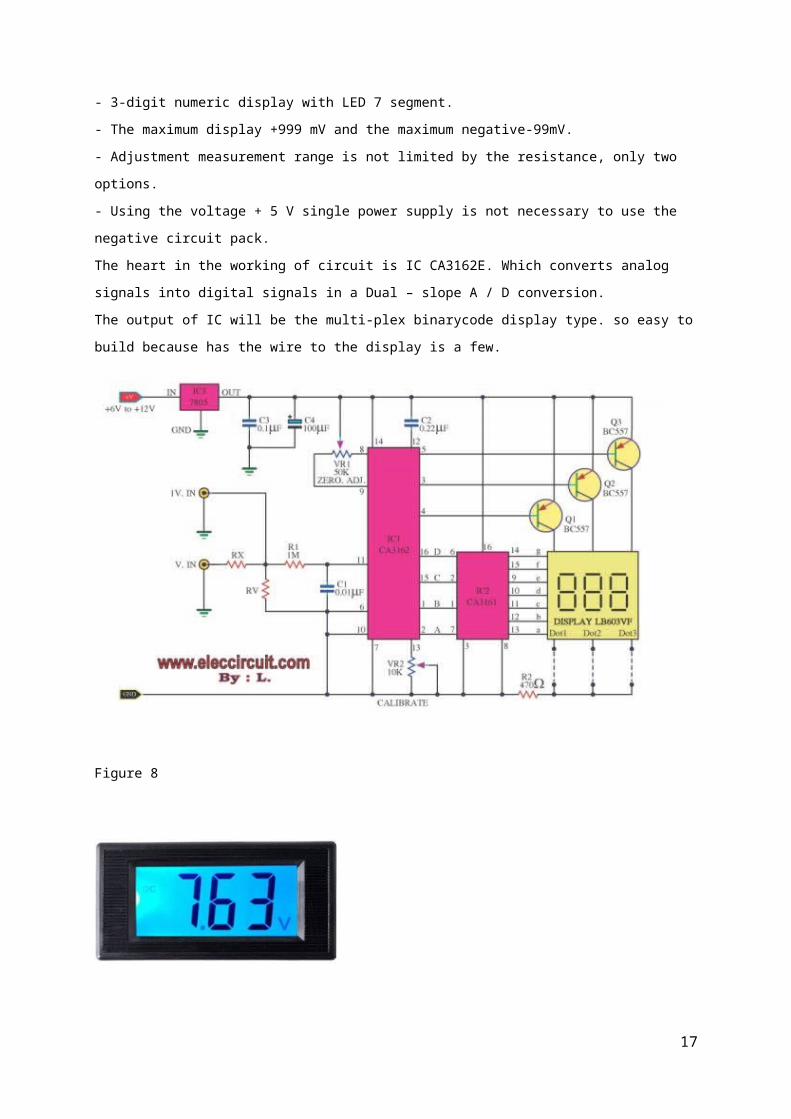
- 3-digit numeric display with LED 7 segment.
- The maximum display +999 mV and the maximum negative-99mV.
- Adjustment measurement range is not limited by the resistance, only two options.
- Using the voltage + 5 V single power supply is not necessary to use the negative circuit pack.
The heart in the working of circuit is IC CA3162E. Which converts analog signals into digital signals in a Dual –
slope A / D conversion.
The output of IC will be the multi-plex binarycode display type. so easy to build because has the wire to the
display is a few.
Figure 8
13

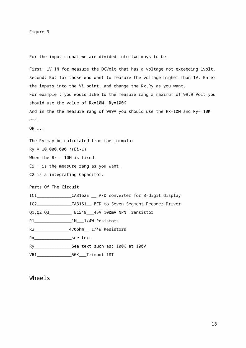
Figure 9
For the input signal we are divided into two ways to be:
First: 1V.IN for measure the DCVolt that has a voltage not exceeding 1volt.
Second: But for those who want to measure the voltage higher than 1V. Enter the inputs into the Vi point, and
change the Rx,Ry as you want.
For example : you would like to the measure rang a maximum of 99.9 Volt you should use the value of
Rx=10M, Ry=100K
And in the the measure rang of 999V you should use the Rx=10M and Ry= 10K etc.
OR …..
The Ry may be calculated from the formula:
Ry = 10,000,000 /(Ei-1)
When the Rx = 10M is fixed.
Ei : is the measure rang as you want.
C2 is a integrating Capacitor.
Parts Of The Circuit
IC1______________CA3162E __ A/D converter for 3-digit display
IC2______________CA3161__ BCD to Seven Segment Decoder-Driver
Q1,Q2,Q3_________ BC548___45V 100mA NPN Transistor
R1_______________1M___1/4W Resistors
R2______________470ohm__ 1/4W Resistors
Rx_______________see text
Ry_______________See text such as: 100K at 100V
VR1______________50K___Trimpot 18T
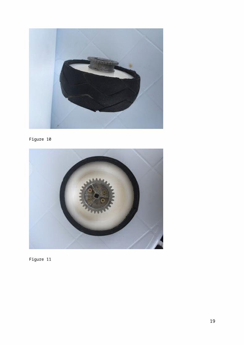
Wheels
14

Figure 10
Figure 11
15

Front wheels
Figure 12
16
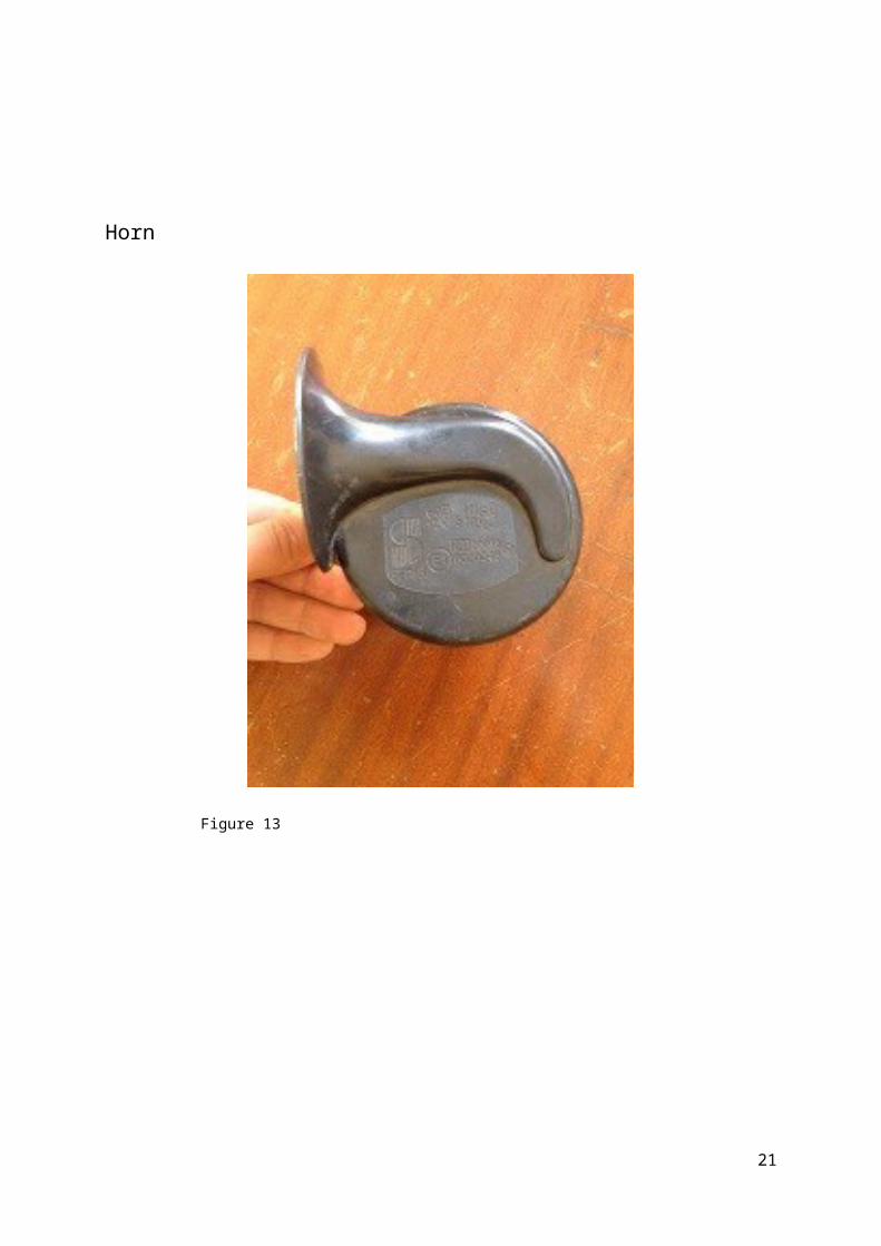
Horn
Figure 13
17
Metal frame of the wheelchair
Figure 14
18
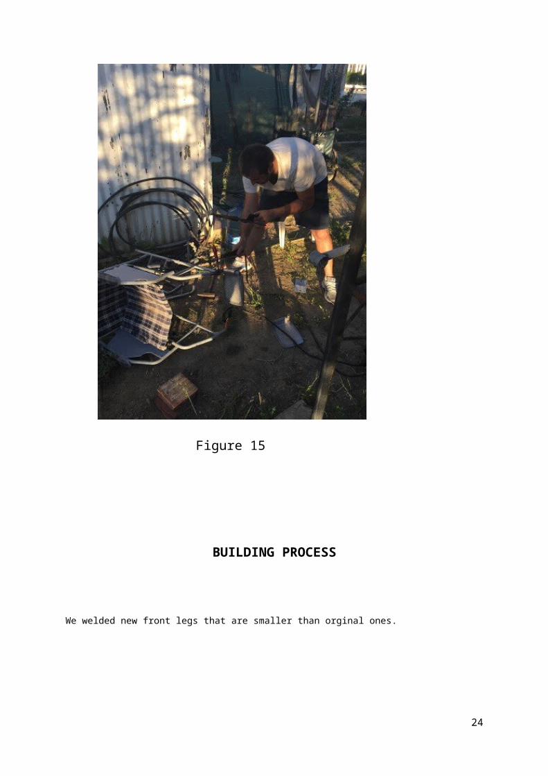
BUILDING PROCESS
First we took off the orginal wheels of the wheelchair , then
we took out the orginal elevating leg rests and we welded new leg rests
Figure 15
19
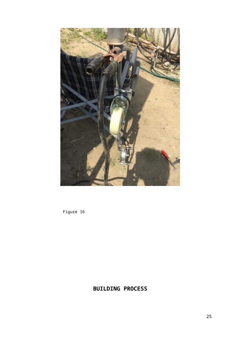
BUILDING PROCESS
We welded new front legs that are smaller than orginal ones.
Figure 16
20
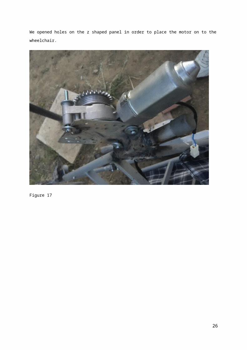
BUILDING PROCESS
We opened holes on the z shaped panel in order to place the motor on to the wheelchair.
Figure 17
21

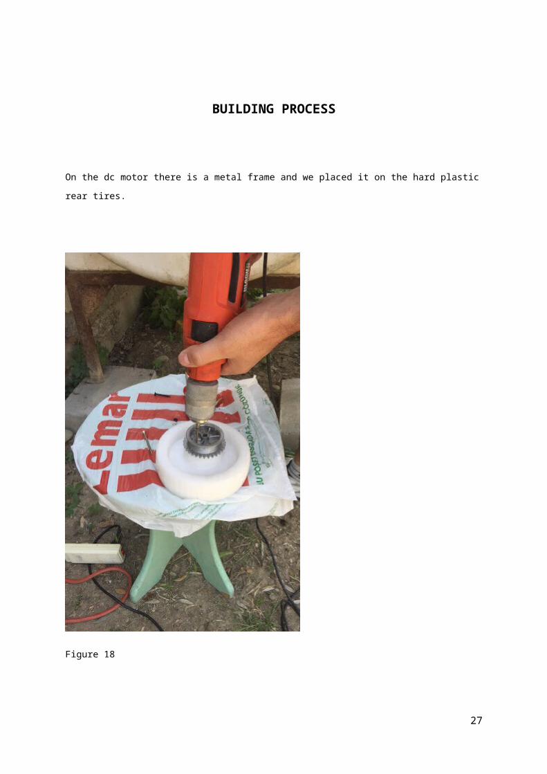
BUILDING PROCESS
On the dc motor there is a metal frame and we placed it on the hard plastic rear tires.
Figure 18
22
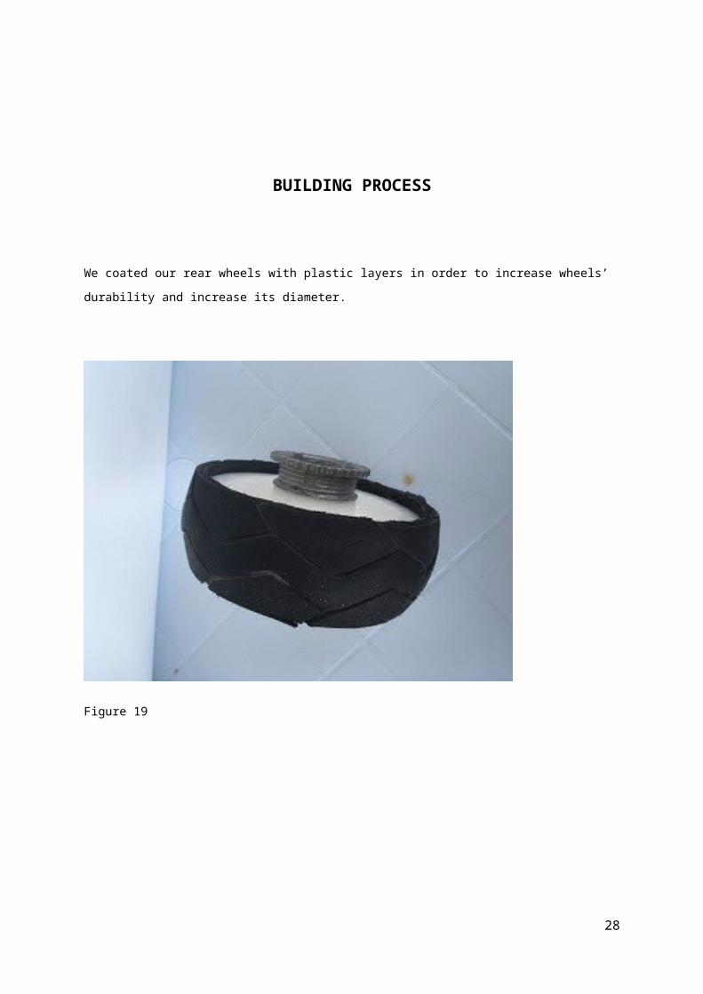
BUILDING PROCESS
We coated our rear wheels with plastic layers in order to increase wheels’ durability and increase its diameter.
Figure 19
23

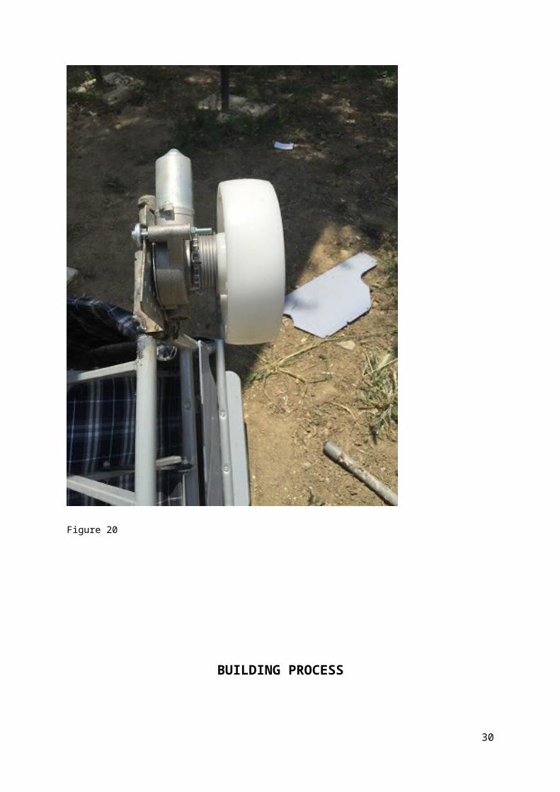
BUILDING PROCESS
We placed our coated wheels on the electric motor.
Figure 20
24

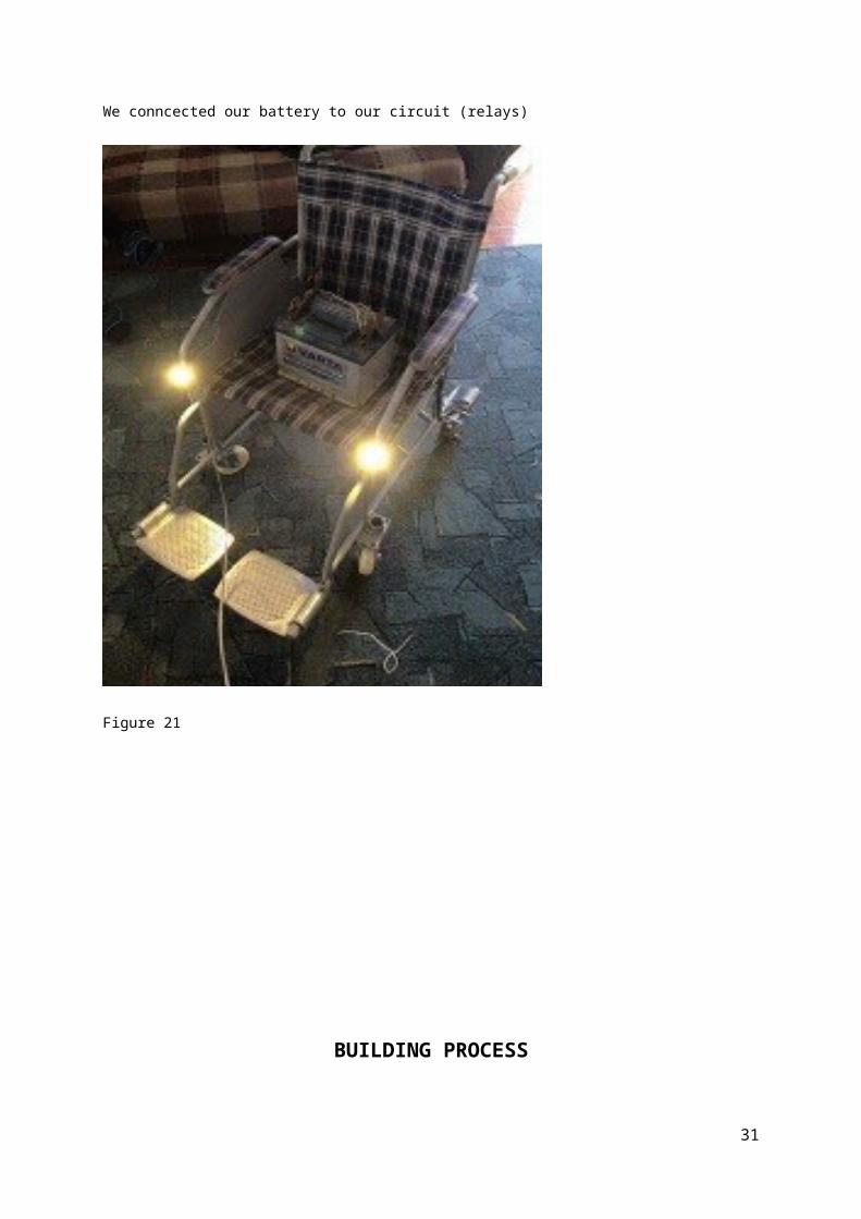
BUILDING PROCESS
We conncected our battery to our circuit (relays)
Figure 21
25
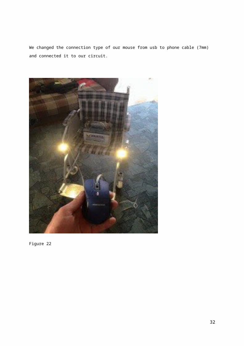
BUILDING PROCESS
We changed the connection type of our mouse from usb to phone cable (7mm) and connected it to our circuit.
Figure 22
26
MOVEMENT MECHANISM
Straight
As we said before our PC Mouse will contain two buttons.Chair will go straight if we push both buton.
When both buttons pushed each relays connected to each wheels become completed (smaller
ampere will cause magnetic field and this magnetic will pull metal part of relay and this metal part
will change its posittion) because of that main power from battery will directed from its source to
electrical wheels. Both electrical motor will start to work and each wheel start to turn.
Turning Principle
Wheelchair will go left if we push the left buton when left buton is pushed right relay will connect right wheel
(smaller ampere will cause magnetic field and this magnetic will pull metal part of relay and this metal part will
change its position) because of that main power from battery will directed from its source to electrical wheels.
Right electrical motor will work.While leff wheel won’t turn when right wheel turns our wheel chair will turn
left.
MOVEMENT MECHANISM
Stopping Principle
When there is no electic given the motors will not move since they have a gearmechanism.
27
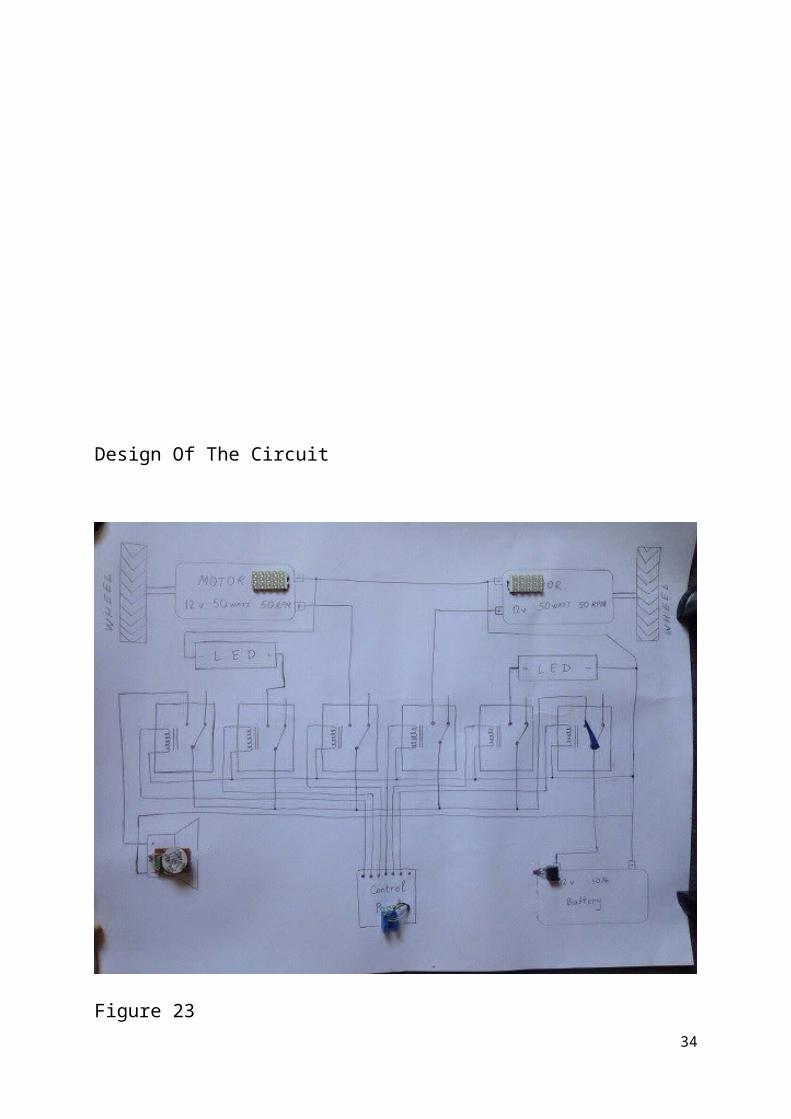
Design Of The Circuit
Figure 23
28
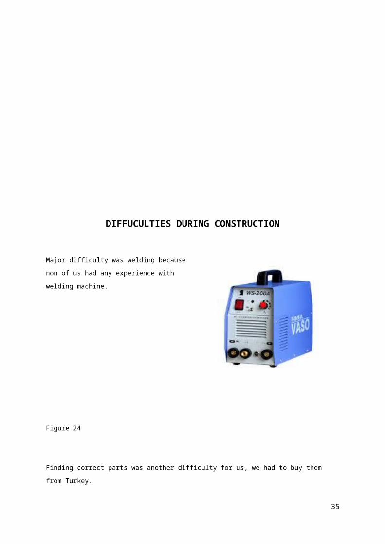
DIFFUCULTIES DURING CONSTRUCTION
Major difficulty was welding because non of us had
any experience with welding machine.
Figure 24
Finding correct parts was another difficulty for us, we had to buy them from Turkey.
Coating the rear wheels was another difficulty we couldn’t find any ready tire casing so we found a motorcycle
tires and cut it in to the pieces and just used the middle part of it.
ADVANTAGES
29
You can fold it easly just by removing battery.
Using mouse as controller : minimizing the patients’ hand movement (just using 2 finger will be
enough.)
You can easily remove electric motors if there is a problem.(They are not hidden under the metal
frame.)
It is very light when you compare it with other wheelchairs.
30

DISADVANTAGES
There is no alarm system for battery life.
We didn’t weld our motors on main metal frame,we welded them on a thin metal plate.So if there is too
much weight metal plate can fold to a wider angle.
It is not comfortable as other wheelchairs,since we used a limited budget .
With these parts it can not go backwards.
31
CURRENT DEVICES
Cirrus Plus HD Compact Mid-Wheel
Figure 25 Figure 26
Compass SportMedalist P22
Figure 27 Figure 28
32
CURRENT DEVICES
Pride Go-Chair TravelPride Jazzy 600
Figure 29 Figure 30
Pride Jazzy Elite HDPronto M51
Figure 31 Figure 32
33
CURRENT DEVICES
Quickie Xtender Power AssistZip'r PC
Figure 33 Figure 34
34

FUTURE IMPROVEMENTS
Adding backward movement.
Building it more higher off the ground .
We can use bigger tires which means using stronger motors .
We can add a mechanism that will raise the seat.
We can add ultrasound sensors around the wheelchair that will warn us if there is an obstacle.
We can add suspension to wheels in order to improve durability of wheelchair.
35
REFERENCES
http://electric-wheelchairs-review.toptenreviews.com/
http://themobilityproject.com/directory/list/wheelchair-power.aspx
http://en.wikipedia.org/wiki/Motorized_wheelchair
http://en.wikipedia.org/wiki/Light-emitting_diode
http://www.abledata.com/abledata_docs/Powered_Wheelchairs.htm
http://www.motionspecialties.com/component/virtuemart/?
page=shop.browse&category_id=2&Itemid=101
http://www.pridemobility.com.au/index.cfm/buyers-guide/power-chairs-or-electric-wheelchairs/
http://www.1800wheelchair.ca/browse/137/motorized-wheelchair
http://www.sunrisemedical.co.uk/products/quickie/power-wheelc
hairs.aspx
http://en.wikipedia.org/wiki/Mouse_%28computing%29
http://en.wikipedia.org/wiki/Direct_current
http://en.wikipedia.org/wiki/Diode
http://en.wikipedia.org/wiki/Relay
36
APPENDIX Suspension is the system of springs, shock absorbers and linkages that connects a vehicle to
its wheels and allows relative motion between the two.
Four Wheel Drive is a transmission system which provides power directly to all four wheels of a
vehicle.
Relay is an electrically operated switch. Many relays use an electromagnet to mechanically
operate a switch, but other operating principles are also used, such as solid-state relays.
LED is a light-emitting diode (LED) is a two-lead semiconductor light source.
Diode is a two-terminal electronic component with asymmetric conductance; it has low
(ideally zero) resistance to current in one direction, and high (ideally infinite) resistance in the
other.
DC Motor relies on the fact that like magnet poles repel and unlike magnetic poles attract each
other. A coil of wire with a current running through it generates an electromagnetic field
aligned with the center of the coil. By switching the current on or off in a coil its magnetic
field can be switched on or off or by switching the direction of the current in the coil the
direction of the generated magnetic field can be switched 180°.
Voltmeter is an instrument used for measuring electrical potential difference between two
points in an electric circuit.
Astable Multi Vibrator is an electronic circuit used to implement a variety of simple two-state
systems such as oscillators, timers and flip-flops.
Wheel is a circular component that is intended to rotate on an axial bearing.
Magnetic Field is the magnetic influence of electric currents and magnetic materials.
Voltage is the electric energy charge difference of electric potential energy transported
between two points.
Direct current (DC) is the unidirectional flow of electric charge.
Capacitor (originally known as a condenser) is a passive two-terminal electrical
component used to store energy electrostatically in an electric field.
Mouse (PC) In computing, a mouse is a pointing device that detects two-dimensional motion
relative to a surface.
37


![ACKNOWLEGEMENT Scan rate (mV/s) Raman Shift (cmphantomsfoundation.com/ONLINE/IM2020/Posters/IM2020...[4] Supria Chakrabarti et al., Nanoscale Adv. 1 (2019) 4915-4925. [5] Christian](https://static.fdocuments.in/doc/165x107/613e15a759df642846164e43/acknowlegement-scan-rate-mvs-raman-shift-4-supria-chakrabarti-et-al.jpg)