ACI SP-183 the Design of Two-Way Slabs
184
Copyright American Concrete Institute Provided by IHS under license with ACI Not for Resale, 10/05/2011 10:37:39 MDT No reproduction or networking permitted without license from IHS --`,``,,`,,`,,,,`,``,,,`,`,,,`,-`-`,,`,,`,`,,`---
-
Upload
dockdodger -
Category
Documents
-
view
956 -
download
398
description
ACI SP-183 the Design of Two-Way Slabs
Transcript of ACI SP-183 the Design of Two-Way Slabs
Copyright American Concrete Institute Provided by IHS under license with ACI Licensee=AECOM User Geography and Business Line/5906698001, User=Elmorsi, Mostaf
Not for Resale, 10/05/2011 10:37:39 MDTNo reproduction or networking permitted without license from IHS
--`,``,,`,,`,,,,`,``,,,`,`,,,`,-`-`,,`,,`,`,,`---
~~
Obb2949 054395b 92T W
The Design of Two-way Slabs
Editor T. C. Schaeffer
international SP-183
Copyright American Concrete Institute Provided by IHS under license with ACI Licensee=AECOM User Geography and Business Line/5906698001, User=Elmorsi, Mostaf
Not for Resale, 10/05/2011 10:37:39 MDTNo reproduction or networking permitted without license from IHS
--`,``,,`,,`,,,,`,``,,,`,`,,,`,-`-`,,`,,`,`,,`---

0bb2949 0543957 öbb W
DISCUSSION of individual papers in this symposium may be submitted in accordance with general requirements of the AC1 Publication Policy to AC1 headquarters at the address given below. Closing date for submission of discussion is November 1, 1999. Ail discussion approved by the Technical Activities Committee along with closing remarks by the authors will be published in the MarcWApril 2000 issue of either AC1 Structu ral Journal or AC1 IWgxids Journal depending on the subject emphasis of the individual paper.
The Institute is not responsible for the statements or opinions expressed in its publications. Institute publications are not able to, nor intended to, supplant indi- vidual training, responsibility, or judgment of the user, or the supplier, of the information presented.
The papers in this volume have been reviewed under Institute publication proce- dures by individuals expert in the subject areas of the papers.
Copyright O 1999 AMERICAN CONCRETE INSTITUTE
P.O. Box 9094 Farmington Hills, Michigan 48333-9094
All rights reserved including rights of reproduction and use in any form or by any means, including the making of copies by any photo process, or by any electronic or mechanical device, printed or written or oral, or recording for sound or visual reproduction or for use in any knowledge or retrieval system or device, unless permission in writing is obtained from the copyright proprietors.
Printed in the United States of America
Editorial production: Jane D. Carroll
Library of Congress catalog card number: 99-61474
Copyright American Concrete Institute Provided by IHS under license with ACI Licensee=AECOM User Geography and Business Line/5906698001, User=Elmorsi, Mostaf
Not for Resale, 10/05/2011 10:37:39 MDTNo reproduction or networking permitted without license from IHS
--`,``,,`,,`,,,,`,``,,,`,`,,,`,-`-`,,`,,`,`,,`---
m O662949 0543958 7T2 m
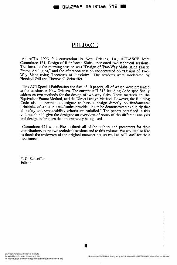
PREFACE
At ACI’s 1996 fall convention in New Orleans, La., ACI-ASCE Joint Committee 421, Design of Reinforced Slabs, sponsored two technical sessions. The focus of the morning session was “Design of Two-way Slabs using Elastic Frame Analogies,” and the afternoon session concentrated on “Design of Two- Way Slabs using Theorems of Plasticity.” The sessions were moderated by Hershel1 Gill and Thomas C. Schaeffer.
This AC1 Special Publication consists of 10 papers, all of which were presented at the sessions in New Orleans. The current AC1 3 18 Building Code specifically addresses two methods for the design of two-way slabs. These methods are the Equivalent Frame Method, and the Direct Design Method. However, the Building Code also “...permits a designer to base a design directly on fundamental principles of structural mechanics provided it can be demonstrated explicitly that all safety and serviceability criteria are satisfied.” The papers contained in this volume should give the designer an overview of some of the different analysis and design techniques that are currently being used.
Committee 421 would like to thank all of the authors and presenters for their contributions to the two technical sessions and to this volume. We would also like to thank the reviewers of the original manuscripts, as well as AC1 staff for their assistance.
T. C. Schaeffer Editor
Copyright American Concrete Institute Provided by IHS under license with ACI Licensee=AECOM User Geography and Business Line/5906698001, User=Elmorsi, Mostaf
Not for Resale, 10/05/2011 10:37:39 MDTNo reproduction or networking permitted without license from IHS
--`,``,,`,,`,,,,`,``,,,`,`,,,`,-`-`,,`,,`,`,,`---
Obb2949 0543959 639
CONTENTS
CONCEPT AND BACKGROUND OF ELASTIC FRAME ANALOGIES FOR
by S. Simmonds ................................................................................................... 1 TWO-WAY SLAB SYSTEMS
DESIGN FOR SEVERE DYNAMIC LOADS by S. Woodson and T. Krauthammer ................................................................. 17
DESIGN FOR PUNCHING SHEAR IN CONCRETE by S. Megaily and A. Ghali ............................................................................... 37
DEVELOPMENT IN YIELD LINE THEORY FOR SLABS by W. Gamble .................................................................................................... 67
USING THEORUMS OF PLASTICITY HISTORY AND CONCEPT by S. Simmonds ................................................................................................. 77
STRIP METHOD FOR FLEXURAL DESIGN OF TWO-WAY SLABS by S. Alexander .................................................................................................. 93
PLANE-FRAME ANALYSIS APPLIED TO SLABS by W. Gamble ................................................................................................... 119
DETAILING FOR SERVICEABILITY by D. Rogowsky .............................................................................................. 13 1
DESIGN AND CONSTRUCTION OF TWO-WAY SLABS FOR DEFLECTION CONTROL by A. Scanlon ................................................................................................... 145
STRIP DESIGN FOR PUNCHING SHEAR by S. Alexander ................................................................................................ 161
V
Copyright American Concrete Institute Provided by IHS under license with ACI Licensee=AECOM User Geography and Business Line/5906698001, User=Elmorsi, Mostaf
Not for Resale, 10/05/2011 10:37:39 MDTNo reproduction or networking permitted without license from IHS
--`,``,,`,,`,,,,`,``,,,`,`,,,`,-`-`,,`,,`,`,,`---
0bb2949 05439b0 350
SP 183-1
Concept and Background of Elastic Frame Analogies for Two-way Slab Systems
by S. Simmonds
Synopsis: The justification for using elastic frame analogies to determine design moments in two-way slab systems is discussed. A brief history of two-way reinforced concrete slab design leading to the current code procedures is presented. This history includes a description of the various elastic frame analogies that have existed in past codes, the reasons for changes and the research leading to improved frame analogies. This is followed by a critical review of the Equivalent Frame Method in the current code with suggestions for improving and simplifying provisions for elastic frame analogies in future codes.
Keywords: analysis; design; elastic frames; history; reinforced concrete slabs
1
Copyright American Concrete Institute Provided by IHS under license with ACI Licensee=AECOM User Geography and Business Line/5906698001, User=Elmorsi, Mostaf
Not for Resale, 10/05/2011 10:37:39 MDTNo reproduction or networking permitted without license from IHS
--`,``,,`,,`,,,,`,``,,,`,`,,,`,-`-`,,`,,`,`,,`---
D Obb2947 05437b3 297 2 Simmonds
Sidney H. Simmonds, currently Professor Emeritus, University of Alberta was for many years Secretary of the Canadian Concrete Code Committee A23.3. He also served on AC1 Committees; 118 - Computers (Chairman 1979-83), 120 - History (Chairman 1991-95), 318F - d c on Slabs, 334 - Shells, 340 - Handbook, 421 - Slabs, and was a founding member and first President of the Alberta AC1 Chapter.
WHY AN ELASTIC FRAME ANALOGY?
Two-way slab systems are a common structural component in reinforced concrete construction. If asked how they design these slabs, many designers in North America would answer 'I use a computer program'. If pressed as to the methodology incorporated in the program they would likely respond 'elastic frame analogy'. Why an elastic frame analogy?
Traditionally, in reinforced concrete design, one uses a linear elastic theory to determine design parameters and then proportions members using an ultimate strength procedure. The justification for this apparent anomaly is that by designing for moments determined from elastic theory the amount of moment redistribution at service load conditions will be minimized thereby ensuring that serviceability requirements will generally be satisfied. Except for special cases such as deep beams or sudden changes in cross section where elastic theory is not applicable, this technique has served us well.
To apply a similar procedure to the design of two-way slab systems it is necessary to have a means of obtaining an elastic analysis. As early as 18 11 , Lagrange proposed an elastic theory for thin slabs which requires determining a fiinction that will satis@ both a fourth-order differential equation and the boundary conditions. Solutions using this approach have been successful only for slabs with the simplest idealized boundary conditions, generally panels with non-deflecting boundaries. This method has been used to develop design procedures for slabs with beams between all supports. It was the need to provide a simple elastic analysis for column supported two-way slab systems that led to the concept of an elastic frame analogy.
Even today, although a number of ingenious techniques to obtain solutions for two-way systems have been proposed, for example Ang (1) and, more recently, numerical solutions based on finite element or finite difference techniques, none have proved practical for routine ofice use. Hence the continuing interest in elastic frame analogies.
WHAT IS AN ELASTIC FRAME ANALOGY?
The concept behind the use of elastic frame analogies is that satisfactory values for the design moments and shears in two-way slab systems can be obtained by considering a portion of the slab-column structure to form a design frame that can be analyzed as a plane frame.
a) define the analogous plane frame including assigning member stiffness The process consists of three parts:
Copyright American Concrete Institute Provided by IHS under license with ACI Licensee=AECOM User Geography and Business Line/5906698001, User=Elmorsi, Mostaf
Not for Resale, 10/05/2011 10:37:39 MDTNo reproduction or networking permitted without license from IHS
--`,``,,`,,`,,,,`,``,,,`,`,,,`,-`-`,,`,,`,`,,`---
= 0543qb2 Design of Two-way Slabs 3
b) analyze frame with appropriate loading to obtain maximum frame moments, and c) distribute frame moments laterally across the corresponding critical sections of the slab.
Frame analogies can be used for both gravity and lateral loading on slab- column structures.
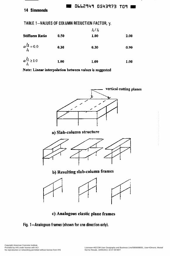
The basic approach for defining the geometry of the analogous elastic plane frames has remained essentially unchanged through various codes. The structure is considered to be made up of analogous or equivalent frames centered on the column lines taken longitudinally and transversely through the building, see Fig. 1. Each frame consists of a row of columns or supports and slab-beam strips bounded laterally by the centerline of the panel on each side of the centerline of the columns or supports. Frames adjacent and parallel to an edge are bounded by that edge and the centerline of the adjacent panel. Each frame may be analyzed in its entirety, or for vertical loading each floor or roof with attached columns may be analyzed separately.
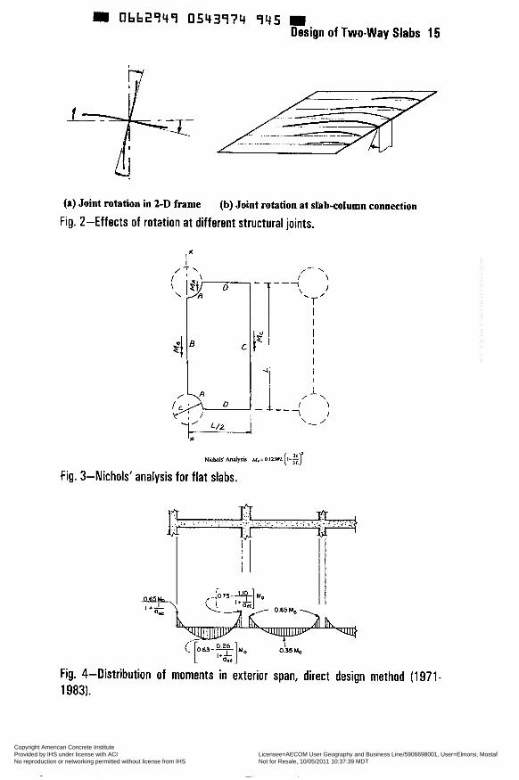
Success in applying this analogy depends on the appropriate apportioning of stiffness to the members of the frame so that the elastic analysis of the two- dimensional frame will approximate that of the non-linear three-dimensional slab- beam-column system. This problem is made more complex by a fundamental assumption in the analysis of plane frames that does not apply to slab-column systems. In a typical plane frame analysis it is assumed that at a beam-column connection all members framing into that joint undergo the same rotation as shown in Fig. 2(a). For slabs supported by columns this assumption is valid only locally at the column. Portions of the slab laterally removed from the column will rotate lesser or greater amounts depending on the geometry and loading patterns as shown in Fig. 2(b). Furthermore, actual slab systems crack even under service loading, especially near the face of the column resulting in locally reduced stiffness. To account for the differences in behavior of the actual slab-column system and the idealized plane frame, it is necessary to modi@ the stiffness of the frame elements. Unfortunately, the modifications required to the member stiffness for lateral loading differ fiom those for gravity loading.
The definition of the analogous frame, the apportioning of stiffness and the rules for the lateral distribution of design moments across the slab have evolved through successive codes. To follow this evolution, it is helpful to review the history of the development of two-way slab construction.
'TWO-WAY SLABS' AND 'FLAT SLABS'
Since the 1971 AC1 Code, the term 'two-way slab' refers to all slab systems reinforced for flexure in more than one direction with or without beams between supports. The term 'flat slab' is not used. Prior to 1971, the term 'two-way slab' referred only to those slabs with beams between supports along all sides of each panel and the term 'flat slab' referred to slabs without beams between supports but could have column capitals andlor drop panels. The need for the distinction in earlier codes was because of the different genesis of the two slab types and the resulting differences in design rules. The elastic frame method was initially
Copyright American Concrete Institute Provided by IHS under license with ACI Licensee=AECOM User Geography and Business Line/5906698001, User=Elmorsi, Mostaf
Not for Resale, 10/05/2011 10:37:39 MDTNo reproduction or networking permitted without license from IHS
--`,``,,`,,`,,,,`,``,,,`,`,,,`,-`-`,,`,,`,`,,`---
9 Obb2949 05439b3 ObT W 4 Sirnrnonds
developed for two-way slabs without beams (flat slabs). In the remainder of this paper the term flat slab is used as defined above when discussing design rules prior to 1971.
EARLY HISTORY OF SLAB DESIGN
Reinforced concrete flat slabs were invented in the sense that they were not a logical extension of elastic theory or construction practice. Credit for this invention is generally given to C. A. P. Turner who constructed his first 'mushroom slab' (a reinforced concrete slab supported on columns with flared column capitals) for the five-story C. A. Bovey Building in Minneapolis in 1906. Lacking a rational analysis, the validity of his design was verified with a load test. So successful was this slab that almost immediately competitors were constructing slabs using various proprietary methods. Since there was no generally accepted procedure for analyzing such slabs, it is not surprising that the amount of reinforcement required varied considerably fiom design to design. A comparison of the amounts of reinforcement required in an interior panel by six different design procedures made by McMillan (2) in 1910 showed that some designs required four times as quch steel as others.
In an attempt to reconcile these difference in designs, many of the slabs that were load tested had measurements of the strains in the reinforcement. Moments in the slab were computed from these steel strains using a straight line expression. These tests did not resolve the differences in design procedures.
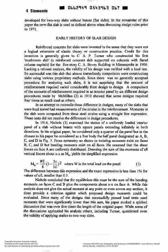
In 1914, Nichols (3) examined the statics of a uniformly loaded interior panel of a slab without beams with square panels extending infinitely in both directions. In his original paper, he considered only a quarter of the panel but in the closure to his paper he considered as a free body the half panel designated as A, B, C, and D in Fig. 3. From symmetry no shears or twisting moments exist on faces B, C, and D but bending moments exist on all faces. He assumed that the shear forces on face A are uniformly distributed. Denoting the sum of the moments of all vertical forces about x-x as M,,, yields the simplified expression
(1) WL 2c 8 3L
Mo = -(1--)2 where W is the total load on the panel.
The difference between this expression and the exact expression is less than 1% for values of CL smaller than 0.3.
Nichols concluded that for equilibrium this must be the sum of the bending moments on faces C and B plus the components about x-x on face A. While this analysis does not give the actual moment at any point or even across any section, it does provide a criterion against which proposed design moments could be evaluated. Since many of the designs that successfully passed load tests used moments that were significantly lower than this sum, his paper evoked a spirited discussion that was over five times the length of the original paper. While some of the discussions applauded his analysis others, including Turner, questioned even the validity of applying statics to two-way slabs.
Copyright American Concrete Institute Provided by IHS under license with ACI Licensee=AECOM User Geography and Business Line/5906698001, User=Elmorsi, Mostaf
Not for Resale, 10/05/2011 10:37:39 MDTNo reproduction or networking permitted without license from IHS
--`,``,,`,,`,,,,`,``,,,`,`,,,`,-`-`,,`,,`,`,,`---
O662949 05439h4 TTb Design of Two-way Slabs 5
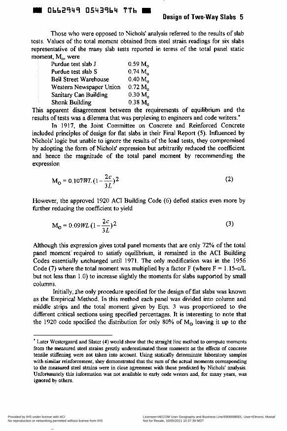
Those who were opposed to Nichols' analysis referred to the results of slab tests. Values of the total moment obtained from steel strain readings for six slabs representative of the many slab tests reported in terms of the total panel static moment, Mo, were
Purdue test slab J 0.59 Mo Purdue test slab S 0.74 Mo Bell Street Warehouse 0.40 M,, Western Newspaper Union 0.72 Mo Sanitary Can Building 0.30 Mo Shonk Building 0.38 M,,
This apparent ' disagreement between the requirements of equilibrium and the results of tests was a dilemma that was perplexing to engineers and code writers.'
In 1917, the Joint Committee on Concrete and Reinforced Concrete included principles of design for flat slabs in their Final Report (5 ) . Influenced by Nichols' logic but unable to ignore the results of the load tests, they compromised by adopting the form of Nichols' expression but arbitrarily reduced the coefficient and hence the magnitude of the total panel moment by recommending the expression
2c 3L
Mo = 0.107WL (1 - -)2
However, the approved 1920 AC1 Building Code (6) defied statics even more by firther reducing the coefficient to yield
2c 3L
Mo= 0.09WL(1--)2
Although this expression gives total panel moments that are only 72% of the total panel moment' required to satis@ equilibrium, it remained in the AC1 Building Codes essentially unchanged until 1971. The only modification was in the 1956 Code (7) where the total moment was multiplied by a factor F (where F = 1.15-cL but not less than 1 .O) to increase slightly the moments for slabs supported by small columns.
Initially, lhe only procedure specified for the design of flat slabs was known as the Empirical Method. In this method each panel was divided into column and middle strips and the total moment given by Eqn. 3 was proportioned to the different critical sections using specified percentages. It is interesting to note that the 1920 code specified the distribution for only 80% of Mo leaving it up to the
* Later Westergaard and Slater (4) would show that the straight line method to compute moments from the measured steel strains greatly underestimated these moments as the effects of concrete tensile stiffening were not taken into account. Using statically determinate laboratory samples with similar reinforcement, they demonstrated that the sum of the actual moments corresponding to the measured steel strains were in close agreement with those predicted by Nichols' analysis. Unfortunately this information was not available to early code writers and, for many years, was ignored by others.
Copyright American Concrete Institute Provided by IHS under license with ACI Licensee=AECOM User Geography and Business Line/5906698001, User=Elmorsi, Mostaf
Not for Resale, 10/05/2011 10:37:39 MDTNo reproduction or networking permitted without license from IHS
--`,``,,`,,`,,,,`,``,,,`,`,,,`,-`-`,,`,,`,`,,`---

0662749 0543765 932 6 Simmonds
designer to distribute the remaining 20% "as required by the physical details and dimensions of the particular design employed". In the 1928 code and all following codes until 1971, designer discretion was removed and M, from Eqn. 3 was distributed as follows:
Negative Moment Positive Moment Column Strip 46 22 Middle strip 16 16
ORIGIN OF ELASTIC FRAME ANALOGIES
In 1929, a subcommittee of the reinforced concrete section of the Uniform Building Code, California edition, was established to investigate the idea of considering a flat slab and its supporting columns as a series of elastic frames. Although the report of this subcommittee was not published until 1938 by Dewell and Hamnd (8), it did lead to the inclusion of an Elastic Frame Method as an alternative method for flat slab systems in the 1933 California edition of the Uniform Building Code. This method defined the frames as bounded by the centerlines of the panels as we do today. Columns were modeled as having hinges at the mid-height between the base of the capital and the top of the floor below. The column-slab joints were considered rigid.
Since the elastic frame analysis satisfied the equations of equilibrium, the design moments were considerably greater than those from the Empirical Method which accounted for only 72% of the static moment. This inconsistency was eliminated by arbitrarily reducing the negative moments obtained from the frame analysis by 40%. These positive and negative moments were distributed to column and middle strips in the same proportions specified for the Empirical Method.
An elastic frame method was first introduced into the AC1 Code in 1941. The geometry for the equivalent frames followed closely that proposed by Dewell and Hammil except that the columns were assumed fixed at their far ends. The joints between columns and slabs were considered rigid. This rigidity was assumed to extend in the slabs a distance A, (where A was the distance from the center of the column, in the direction of the span, to the intersection of a 45 degree diagonal from the center of the column to the bottom of the flat slab or drop panel but not greater than one-eighth of the span) and in the column to the intersection of the sides of the column and the 45 degree line defining A. Negative moment was computed at a distance 0.073L +0.57A from the column center-line, this distance being selected to result in total panel moments for interior square panels with uniform loading that agreed closely with those that would be obtained with the Empirical Method. Thus the effect was essentially the same as merely reducing the negative moments by 40 % as specified by the UBC, California Edition, but was not as transparent to or as easy for the designer,
The elastic frame method was modified in the 1956 Code so that the rigid joint extended in slabs from the center of the column to the edge of the column or capital and in the column from the top of slab to the bottom of the capital and the distance from the column center at which negative moments were computed was
Copyright American Concrete Institute Provided by IHS under license with ACI Licensee=AECOM User Geography and Business Line/5906698001, User=Elmorsi, Mostaf
Not for Resale, 10/05/2011 10:37:39 MDTNo reproduction or networking permitted without license from IHS
--`,``,,`,,`,,,,`,``,,,`,`,,,`,-`-`,,`,,`,`,,`---
Obb2949 0543966 879 Design of Two-way Slabs 7
simplified to the length A. With these changes the design moments remained essentially the same as before.
When the live load did not exceed three-quarters of the dead load, the design moments were assumed to occur with full live load on all spans. Otherwise, design moments were obtained with full live load on appropriate spans to give maximum values.
THE ILLINOIS SLAB STUDY
The situation in the early 50's was that flat slabs, even when using an elastic analysis with full span geometry and design loads, resulted in design moments that were substantially less than those required by considerations of equilibrium. On the other hand, two-way slabs (slabs with beams) were designed using coefficients that were in part developed from elastic plate theory and so satisfied equilibrium. As it was generally recognized that there is no essential difference in the behavior between slabs with or without beams, the differences in design procedures and differences in factors of safety needed to be addressed.
To resolve this situation, the Reinforced Concrete Research Council initiated a comprehensive study of slab systems at the University of Illinois, Urbana. This study, begun in September, 1956, involved both laboratory testing and analytical studies. A paper by Sozen and Siess (9) outlines the scope of this study and why it was commissioned.
Five tests of nine panel 1/4 scale slabs with and without beams were tested to failure. These tests confirmed that there was no fundamental difference in their behavior and the existing design rules led to smaller factors of safety for flat slabs. Using the Newmark plate analog to generate difference equations for beams and columns, elastic solutions were obtained for similar slabs for purposes of comparing with the test slabs and for extending the parameters.
The results of this study led to a unified approach to the design of two-way slabs with and without beams in the 1971 AC1 Code.
1971 AC1 CODE PROCEDURES
Two procedures, the Direct Design Method (DDM) and the Equivalent Frame Method (EFM) were introduced to replace the five methods for slab design in the 1963 code. Both methods are essentially frame methods.
The DDM originally considered a design strip similar to the elastic frame but without the interior columns. The total factored panel moment was computed for each span as:
Mo=0.125wl,lf, (4)
where w is the factored design load per unit area, l2 is the span length perpendicular to the design strip and 1, is the clear span length. For interior panels 65% of M, was assigned to the negative moment and 35% to the positive moment. For exterior spans, a modified frame analysis was performed by
Copyright American Concrete Institute Provided by IHS under license with ACI Licensee=AECOM User Geography and Business Line/5906698001, User=Elmorsi, Mostaf
Not for Resale, 10/05/2011 10:37:39 MDTNo reproduction or networking permitted without license from IHS
--`,``,,`,,`,,,,`,``,,,`,`,,,`,-`-`,,`,,`,`,,`---
0662949 0543967 705 D 8 Simmonds
computing a factor, ae, and distributing the moments in the exterior spans as functions of this factor as illustrated in Fig. 4. a, was defined as the ratio at a joint of the stiffness of the equivalent edge column (defined later for the EFM) to the stiffness of a slab-beam element based on gross concrete dimensions. Computing as was extremely tedious and in the 1983 AC1 Code this exterior column computation was replaced with a set of coefficients depending on the edge support. It now resembles the old Empirical Method except that the coefficient for M, is such that it gives a value of total panel moment that is much closer to a Nichols' type analysis.
The EFM replaced the former elastic frame analysis. As part of the Illinois study Corley, Sozen and Siess (10) compared the moments calculated from the elastic frame analogy defined in the 1956 AC1 Code with known elastic solutions. They concluded that, in general, the elastic frame analysis gave values of the positive moment that were to low and values of the negative moment at the column centerline that were to high. Generally the design negative moments after reducing to the critical section were either too high or too low for interior columns depending of the dimensions of the panel and column and too high for exterior columns. To overcome these difficulties required proposing new stiffnesses for the members of the elastic frame. These new stiffnesses incorporated in the EFM were presented by Corley and Jirsa (1 1).
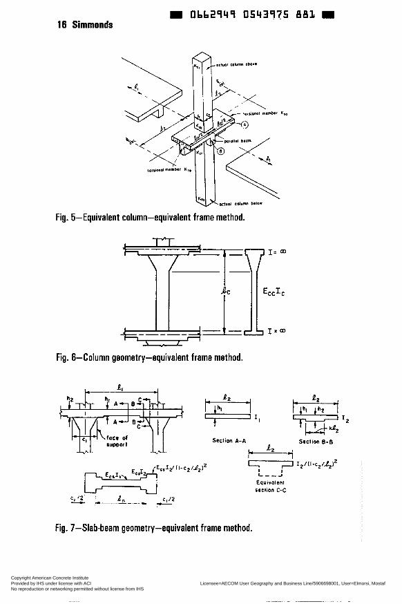
The concept is to introduce torsional members between the columns and slab-beam elements. The reduction in column stiffness is achieved by defining an equivalent column formed by the actual column and attached torsional members as shown in Fig. 5 . Torsional members are assumed to have a constant cross sections throughout their lengths consisting of a portion of slab having a width equal to that of the column or capital plus that portion of the transverse beam above or below the slab, if any. A stiffness K, is computed fiom the expression
where the section parameter C is evaluated for the cross section by dividing it into separate rectangular parts and summing as follows
Copyright American Concrete Institute Provided by IHS under license with ACI Licensee=AECOM User Geography and Business Line/5906698001, User=Elmorsi, Mostaf
Not for Resale, 10/05/2011 10:37:39 MDTNo reproduction or networking permitted without license from IHS
--`,``,,`,,`,,,,`,``,,,`,`,,,`,-`-`,,`,,`,`,,`---
Design of Two-way Slabs 9 Obb2949 05439b8 b4L
The stiffness of the equivalent column is defined as the sum of the flexibilities of the column and torsional member as
(7) 1 1
K e c C K c K I +- - - 1 - -
In computing the stiffness of the columns, K c , the moment of inertia at any cross section outside the joint is based on the gross area of concrete taking into account any variation in section along the axis and at a joint is considered infinite from the top to the bottom of slab-beam. This is shown in Fig. 6.
Similarly, Fig. 7 shows the geometry for a typical slab-beam element where the moment of inertia is based on the concrete section outside the joint but from the center of the column to the face of the column or capital is assumed equal to the moment of inertia at the face of the column or capital divided by the quantity
Since the frame is defined using the centerline dimensions of the members, the negative moments at the column centerlines must be reduced to obtain the design moments at the critical section, defined generally at the face of the supports.
As with previous elastic frame analyses, when the specified live load was less than three-quarters of the specified dead load, design moments were obtained with full factored load on all spans. However, when the specified live load exceeds three-quarters of the specified dead load, the design moments are obtained with full factored dead load on all spans but only three-quarters of factored live load on appropriate spans to give maximum effects.
At the time the EFM was formulated, the only practical solution for elastic frame analysis was the moment distribution procedure, hence the need to determine fixed end moments, distribution factors and carry-over factors for the non-prismatic members resulting from the stiffness definitions. Although approximate values for these parameters for different geometric conditions have been tabulated to assist designers, for example Misic and Simmonds (12), the method is impractical for manual computation. However the concept has been incorporated successfully in computer programs written expressly for these definitions of stiffness and using a slope-deflection formulation.
In both the DDM and the EFM the last step is to distribute the design moments at the critical section across the width of the panel. In the 1971 Code, rules for this distribution to column and middle strips were given as part of the DDM. The definition of the column strip was defined with a width equal to half the
( l-c2/12)2.
Copyright American Concrete Institute Provided by IHS under license with ACI Licensee=AECOM User Geography and Business Line/5906698001, User=Elmorsi, Mostaf
Not for Resale, 10/05/2011 10:37:39 MDTNo reproduction or networking permitted without license from IHS
--`,``,,`,,`,,,,`,``,,,`,`,,,`,-`-`,,`,,`,`,,`---
10 Simmonds - Obb2949 0543969 588
smaller of li or I z centered on the column line instead of half the frame width as was used in previous codes. The middle strip was the remainder of the slab width. The distributiori rules were specified for exterior negative, interior negative and positive moment critical sections and were functions of the panel aspect ratios.
LIMITS FOR APPLICATION OF ELASTIC FRAME ANALOGIES
Until the 1971 Code, the elastic fiame method and all design specifications for flat slabs were explicitly limited to slabs with square or rectangular panels. Ail of the rules for assigning member stiffness and distributing design moments laterally across the slab both before and for the 1971 Code were developed by considering only square or nearly square panels.
Six limitations are listed before the DDM can be used. Three of them, namely, a minimum of three spans, limiting successive span lengths to one-third of the longer span and limiting the ratio of live to dead load are required for the DDM in order for the coefficients used to analyze the design strip to be valid. The remaining three limitations, namely, ratio of longer to shorter spans not greater than 2, column offset to maximum of 10% of span and limits to the effective beam stiffness ratio are required to ensure two-way behavior and the validity of the lateral distribution rules. As such these limitations must also apply for use of the EFM or any other elastic fiame analogy.
While it may be argued that a fiame can be defined for any irregular slab system and this fiame analyzed for any arbitrary gravity loading including point loads, the use of elastic frame analyses as defined by the codes for other than rectangular panels should be viewed with caution. Certainly the lateral distribution of moments in irregular slabs may differ significantly from the rules given in the AC1 code.
FUTURE IMPROVEMENTS TO ELASTIC FRAME ANALOGIES
While there are many areas in which elastic fiame analogies may be improved, only two, simplifjing member stifhess for gravity loading and specifling member stiffness for lateral loading are mentioned here.
It is acknowledged that the attached torsional member concept developed for the EFM generally gives solutions that are closer to elastic solutions than previous fiame analyses. However, the method is unnecessarily complex and the
Copyright American Concrete Institute Provided by IHS under license with ACI Licensee=AECOM User Geography and Business Line/5906698001, User=Elmorsi, Mostaf
Not for Resale, 10/05/2011 10:37:39 MDTNo reproduction or networking permitted without license from IHS
--`,``,,`,,`,,,,`,``,,,`,`,,,`,-`-`,,`,,`,`,,`---
Design of Two-way Slabs 11 W Ob62949 0543970 2 T T E
amount of computation involved for even simple design strips requires specially written computer programs. This might be justified if there were no alternatives or if slab moments had to be determined with great accuracy. Since the EFM is an elastic analysis, many designers interpret the code to permit varying the design moments by up to 20% providing the total static moment is satisfied thereby taking advantage of the moment redistribution in the slab. Aso there are cases when the EFM does not work so well. For example, the attached torsional member concept breaks down when the span in the lateral direction is much greater than the span of the panel. This was recognized by Corley and Vanderbilt (13) who recommended that l2 in Eqn. 5 be the smaller of I , or 12. A better designation for the EFM,
since there are many ways of defining equivalent members, would be 'Elastic Frame with Attached Torsional Member Method'.
The primary purpose of the equivalent column for gravity load analysis is to reduce the effective stiffness of the column. The same result can be obtained by merely using the gross concrete section for the slab-beam and column to obtain the member stiffness but then multiplying the column stiffness by a column reduction factor, y, less than 1. The resulting frame consisting of prismatic members can then be analyzed by any plane frame program based on the direct stiffness method or even by hand calculations. Values of y presented in Table 1 derived by Mulenga and Simmonds (14) result in design moments that are in closer agreement with moments obtained using non-linear analyses at service loads than those given by the EFM. Such a method could be designated as 'Elastic Frame with Column Reduction Factor Method'. Other formulations for assigning stiffness to improve the agreement between the actual and equivalent frames and simpli9 the calculations may yet be proposed.
An elastic frame analogy can also be used to determine moments in slabs forming part of the lateral load resisting structure. The AC1 code allows the results of a lateral load analysis to be algebraically combined with those from gravity load analysis but is silent on how member stiffness should be assigned. In this case it is the slab-beam element stiffness that must be reduced.
Traditionally, for lateral loading, the 'equivalent beam width' concept has been used wherein only a portion of the slab width is considered when determining the slab-beam moment of inertia. An excellent review of this method is given by Vanderbilt and Corley (13). Their paper also describes an 'equivalent beam method' which is similar to the equivalent column in the EFM except that the torsional members are in series with the slab-beam element instead of the column
Copyright American Concrete Institute Provided by IHS under license with ACI Licensee=AECOM User Geography and Business Line/5906698001, User=Elmorsi, Mostaf
Not for Resale, 10/05/2011 10:37:39 MDTNo reproduction or networking permitted without license from IHS
--`,``,,`,,`,,,,`,``,,,`,`,,,`,-`-`,,`,,`,`,,`---
= Obb2949 0543971 b3b 12 Simmonds
element. Unfortunately, this procedure retains the complexities of the EFM and requires a specially written computer program to use. They also discuss the use of a reduction factor, ß, to account for the effects of cracking where ß is the ratio of effective moment of inertia to the gross moment of inertia and recommend a value of ß = 1/3 for lateral load analysis. It is hoped that future AC1 codes will include provisions to assist the engineer in assigning member stiffness for lateral loading of slab-column structures and that these provisions will not require specially written software.
CONCLUSIONS
Elastic frame analogies provide the only practical means for obtaining elastic analyses of column supported two-way slab systems with rectangular panels.
Future AC1 Building Codes should simpli@ the current provisions for modifjhg stiffness for gravity loading. These simplifications should make stiffness a property of the member rather than the joint so that any plane frame analysis program based on the direct stiffness formulation can be used. Provisions for assigning member stiffness for lateral loading of slab-column structures so that they may analyzed as elastic plane frames should also be included.
REFERENCES
1. Ang, A., "The Development of a Distribution Procedure for the Analysis of Continuous Rectangular Plates," Civil Engineering Studies, Structural Research Series No. 176, University of Illinois, Urbana, May, 1959.
2. McMillan, Angus B., "A Comparison of Methods of Computing the Strength of Flat Reinforced Plates," Engineering News, V. 63, No. 13, Mar. 31, 1910, pp. 364-367.
3. Nichols, J. R., "Statical Limitations Upon the Steel Requirements in Reinforced Concrete Flat Slab Floors," Transactions, ASCE, V. 77, 1914, 1670- 1736.
4. Westergaard, H. M. and Slater, W. A., "Moments and Stresses in Slabs," Proceedings, ACI, V 17, 1921, pp. 415-538.
5. Joint Committee on Concrete and Reinforced Concrete, "Final Report," Proceedings, ACI, V 13, 1917, pp. 509-566.
Copyright American Concrete Institute Provided by IHS under license with ACI Licensee=AECOM User Geography and Business Line/5906698001, User=Elmorsi, Mostaf
Not for Resale, 10/05/2011 10:37:39 MDTNo reproduction or networking permitted without license from IHS
--`,``,,`,,`,,,,`,``,,,`,`,,,`,-`-`,,`,,`,`,,`---
0bb2q4q 0543q72 07' Design of Two-way Slabs 13
6. AC1 Committee on Reinforced Concrete and Building Laws, "Standard Building Regulations for the Use of Reinforced Concrete," Proceedings, ACI, V 16, 1920, pp. 283-302.
7. AC1 Committee 3 18, "Building Code Requirements for Reinforced Concrete (ACI318-56)," AC1 Journal, Proceedings, V 52, No. 9, May, 1956, pp. 913-986.
8. Dewell, H. T. and Hammil, H. B., "Flat Slabs and Supporting Columns and Walls Designed as Indeterminate Structural Frames," AC1 Journal, Proceedings, V 34,No. 3, Jan.-Feb. 1938, pp. 321-343.
9. Sozen, M. A. and Siess, C. P., "Investigation of Multi-Panel Reinforced Concrete Floor Slabs: Design Methods-Their Evolution and Comparison," AC1 Journal, Proceedings, V 60, No. 8, Aug. 1963, pp. 999-1028.
10. Corley, W. G., Sozen, M. A. and Siess, C. P., "The Equivalent Frame Analysis for Reinforced Concrete Slabs," University of Illinois, Civil Engineering Studies, Structural Research Series No. 218, June, 1961.
1 1 . Corley, W. G. and Jirsa, J. O., "Equivalent Frame Analysis for Slab Design," AC1 Journal, Proceedings, 67, No. 1 1 , Nov. 1970, pp. 875-884.
12. Simmonds, S. H. and Misic, J., "Design Factors for the Equivalent Frame Method, AC1 Journal, Proceedings, V 68, No. 1 1 , Nov. 1971, pp. 825-831.
13. Vanderbilt, M. D. and Corley, W. G., "Frame Analysis of Concrete Buildings,' Concrete International, Design and Construction, V 5, No. 12, Dec. 1983, pp. 33-43.
14. Mulenga, M. N. and Simmonds, S. H., "Frame Methods for Analysis of Two-way Slabs," Structural Report No 183, Department of Civil Engineering, University of Alberta, Jan. 1993, 23 1 pp.
Copyright American Concrete Institute Provided by IHS under license with ACI Licensee=AECOM User Geography and Business Line/5906698001, User=Elmorsi, Mostaf
Not for Resale, 10/05/2011 10:37:39 MDTNo reproduction or networking permitted without license from IHS
--`,``,,`,,`,,,,`,``,,,`,`,,,`,-`-`,,`,,`,`,,`---
Obb2949 0543973 TO9 14 Simmonds
TABLE 1-VALUES OF COLUMN REDUCTION FACTOR, y,
Stiffness Ratio 0.50 1.00 2.00 12 1 11
ab = 0.0 0.30 0.30 0.90 l i
12
Il a- 2 1.0 1.00 1.00 1.00
Note: Linear interpolation between values is suggested
vertical cutting pianes
a) Slab-column structure
b) Resulting slab-column frames
c) Analogous elastic plane frames
Fig. 1-Analogous frames (shown for one direction only).
Copyright American Concrete Institute Provided by IHS under license with ACI Licensee=AECOM User Geography and Business Line/5906698001, User=Elmorsi, Mostaf
Not for Resale, 10/05/2011 10:37:39 MDTNo reproduction or networking permitted without license from IHS
--`,``,,`,,`,,,,`,``,,,`,`,,,`,-`-`,,`,,`,`,,`---
Obb2949 0543974 945 Design of Two-way Slabs 15
y- --
.- . . ..
(a) Joint rotation in 2-D frame (b) Joint rotation at slab-column connection Fig. 2-Effects of rotation at different structural joints.
'2
Nisholr'hdynr M.=O L?WZ(l-$l
Fig. 3-Nichols' analysis for flat slabs.
Fig. 4-Distribution of moments in exterior span, direct design method (1 971- 1983).
Copyright American Concrete Institute Provided by IHS under license with ACI Licensee=AECOM User Geography and Business Line/5906698001, User=Elmorsi, Mostaf
Not for Resale, 10/05/2011 10:37:39 MDTNo reproduction or networking permitted without license from IHS
--`,``,,`,,`,,,,`,``,,,`,`,,,`,-`-`,,`,,`,`,,`---
= 0662949 0543975 881 M 16 Simmonds
Fig. 5-Equivalent column-equivalent frame method.
Fig. 6-Column
-----
E,&,
geometry-equivalent frame method.
Fig. 7-Slab-beam geometry-equivalent frame method.
Copyright American Concrete Institute Provided by IHS under license with ACI Licensee=AECOM User Geography and Business Line/5906698001, User=Elmorsi, Mostaf
Not for Resale, 10/05/2011 10:37:39 MDTNo reproduction or networking permitted without license from IHS
--`,``,,`,,`,,,,`,``,,,`,`,,,`,-`-`,,`,,`,`,,`---
M Obb2949 054397b 718
SP 183-2
Design for Severe Dynamic loads
by S. Woodson and T. Krauthammer
SynoDsis: Traditionally, U.S. Government agencies have developed and maintained manuals for the design of structures to resist severe dynamic loads, i.e. blast effects. However, such manuais have been primarily directed toward structures of a military nature, and relatively little attention has been given to the design of civilian buildings to resist blast effects. The lack of concern for the blast resistance of buildings is not surprising in that the threat has been minimal. Although some design guidance for blast resistance has been available to the general public, the primary users have been petro-chemical industries that are aware of potential accidental explosions related to their normal operations (i.e., chemical plants). Historically, general design guidance, such as that of the American Concrete Institute?s Committee 3 18 (ACI, 1995) (1) has served the public well. However, two recent events, the World Trade Center and the Alfred P. Murrah explosions, have heightened awareness in the United States of the potential need to consider blast effects in the design of some buildings. The discussion presented herein summarizes existing blast-resistant design approaches and addresses issues that are critical to the development of buildings with improved resistance to severe dynamic loads. Emphasis is given to the design and behavior of reinforced concrete structures.
Keywords: desiy n; dynamic analysis; reinforced concrete; structural steel
17 Copyright American Concrete Institute Provided by IHS under license with ACI Licensee=AECOM User Geography and Business Line/5906698001, User=Elmorsi, Mostaf
Not for Resale, 10/05/2011 10:37:39 MDTNo reproduction or networking permitted without license from IHS
--`,``,,`,,`,,,,`,``,,,`,`,,,`,-`-`,,`,,`,`,,`---
0bb2949 0543977 b54 18 Woodson and Krautharnmer
Dr. Theodor Krauthammer, professor of civil engineering, Penn State, is a recognized researcher in enhanced structural performance and safety with more than twenty-five years experience in protective structures; a member of five technical committees of ACI; and a member of the ASCE Task Committee on Structural Design for Physical Security.
Dr. Stanley Woodson has more than eighteen years experience as a research structural engineer at the U.S. Army Engineer Waterways Experiment Station; serves as an adjunct professor at the WES Graduate Institute; chairman of AC1 370 on Short Duration Dynamics and Vibratory Load Effects; and a member AC1 42 1 on Design of Reinforced Concrete Slabs.
INTRODUCTION
Manuals for Blast-Resistant Design
Numerous reports and publications on weapons effects and structural response to blasts are available in the open literature, but a single document for all aspects of blast-resistant design does not exist. Technical Manual (TM) 5-855-1 (Department of the Army, 1984) (6) serves as the Army’s manual on protective construction, and TM 5-1300 (Department of the Army, the Navy, and the Air Force, 1990) (8) is the Tri-Service Manual for design against accidental explosions. The most widely used non- government blast-resistant design manual is published by the American Society of Civil Engineers (ASCE, 1985) (2) and is hereafter referred to as “ASCE Manual 42.” A summary of the purpose of each manual, as well as some general guidance from each of these references, follows.
Tri-Service Manual íTM 5- 1300). “Structures to Resist the Effects of Accidental Ex~1osions”--Intended primarily for explosives safety applications, TM 5-1300 (Army designation) is the most widely used manual for structural design to resist blast effects. One reason for its widespread use by industry is that it is approved for public release with unlimited distribution. The manual states its purpose: “. . . to present methods of design for protective construction used in facilities for development, testing, production, storage, maintenance, modification, inspection, demilitarization, and disposai of explosive materials.
Copyright American Concrete Institute Provided by IHS under license with ACI Licensee=AECOM User Geography and Business Line/5906698001, User=Elmorsi, Mostaf
Not for Resale, 10/05/2011 10:37:39 MDTNo reproduction or networking permitted without license from IHS
--`,``,,`,,`,,,,`,``,,,`,`,,,`,-`-`,,`,,`,`,,`---
Obb2949 0543978 590 U Design of Two-way Slabs 19
TM 5-1300 distinguishes between a “close-in” design range and a “far” design range for purposes of predicting the mode of response, Based upon the purpose of the structure and the design range, the allowable design response limits for the structural elements (primarily roof and wall slabs) are given in terms of support rotations. Such support rotations are computed simply by taking the arc tan of the quantity given by the predicted midspan deflection divided by one-half the clear span length, e.g. a three-hinge mechanism is assumed.
A unique requirement of TM 5-1300 is the use of lacing bars in certain conditions, particularly for very close-in explosions and for larger values of predicted support rotations. Figure 1 shows schematics of a structurai element with lacing bars and various types of stirrups. Lacing bars are reinforcing bars that extend in the direction parailel to the principal reinforcement and are bent into a diagonal pattern, binding together the two mats of principal reinforcement. It is obvious that the cost of using lacing is considerably greater than that of using stirrups due to the more complicated fabrication and installation procedures.
Amy Technical Manual 5-855-1-TM 5-855-1 is intended for use by engineers involved in designing hardened facilities to resist the effects of conventional weapons. The manual includes design criteria for protection against the effects of a penetrating weapon, a contact detonation, or the blast and fragmentation from a standoff detonation. TM 5-855-1 does not call for the use of lacing, but does require a minimum quantity of stirrups in ali slabs subjected to blast. For beams, one-way slabs, and two-way slabs, the manual recommends a design ductility ratio (ratio of maximum response to yield response) of 5.0 to 10.0 for flexural design. The recommended response limits are only given in terms of ductility ratios, not support rotations. However, a more recent supplement to TM 5-855-1, Engineer Technical Letter (ETL) 1 1 10-9-7 (Department of the Army, 1990) (7), provides response limit criteria based on support rotations.
ASCE Manual 42--The manual was prepared to provide guidance in the design of facilities intended to resist nuclear weapons effects. It attempts to extract concepts from other documents, such as the limited distribution design manual, “The Air Force Manual for Design and Analysis of Hardened Structures”; however, the intent is to provide a more general approach. ASCE Manual 42 presents conservative design ductility ratios for flexural response. Although the manual is an excellent source for general blast-resistant design concepts, it lacks specific guidelines on stnictural details, and it is out of print.
Copyright American Concrete Institute Provided by IHS under license with ACI Licensee=AECOM User Geography and Business Line/5906698001, User=Elmorsi, Mostaf
Not for Resale, 10/05/2011 10:37:39 MDTNo reproduction or networking permitted without license from IHS
--`,``,,`,,`,,,,`,``,,,`,`,,,`,-`-`,,`,,`,`,,`---
20 Woodson and Krauthammer W Obb2949 0543979 427 m
Design Issues
DistanceLoads-It is generally known that the greatest protection against blast effects is distance. The vehicle bomb has become a concern for buildings in the United States in regard to blast effects. Security and trafic route conditions that will prevent close access by an explosives- ladened vehicle are significant protection measures. However, when distance cannot be reasonably guaranteed, specific design issues must be considered. Generally, the potential location for vehicle bombs is in a basement parking garage or in an exterior parking area. Structural protection against a detonation in a basement parking area is rarely feasible. Major structural components may be vulnerable to very close-in blast effects. In such cases, good structural design may only be successful at limiting catastrophic progressive collapse of the building, Additionally, the loading is worsened by partial confinement of the interior explosion. In contrast, external detonations are vented to the outdoor environment, and the potential distance to a major structural element is usually greater than for the basement parking condition.
The manuals listed above, as well as other available literature, provide a means to establish a reasonable approximation of the loading (peak pressure and duration) to be expected for a given explosive threat. The loading referred to is that applied to the exposed surfaces. As openings are created (e.g., windows, walls, and breached floor slabs), the blast loading on subsequent surfaces becomes very difficult to define, and research is continuing in this area. Failed components or sections of structural elements may be propelled into other elements, thereby complicating the loading process. Additionally, heavy failed sections of floor and wall slabs may simply fall by gravity, causing a “pancake” effect on lower floors. Thus, structural details are needed to help prevent progressive collapse.
Columns-A primary concern for buildings is the widespread use of columns. Columns (particularly exterior columns) are avoided in protective structures, and continuous walls are preferred. Columns are generally very stiff against lateral flexural response due to the relatively large quantities of longitudinal reinforcement. Also, compressive forces from gravity loads enhance the laterai strength at initial loading. The consequence is a structural element that will likely respond in a brittle mode, such as shear, unless specifically detailed with adequate confining reinforcement. Fortunately, columns are not generally vulnerable to “far-away” blast loadings, which tend to have lower peak pressures and engulf all sides of
Copyright American Concrete Institute Provided by IHS under license with ACI Licensee=AECOM User Geography and Business Line/5906698001, User=Elmorsi, Mostaf
Not for Resale, 10/05/2011 10:37:39 MDTNo reproduction or networking permitted without license from IHS
--`,``,,`,,`,,,,`,``,,,`,`,,,`,-`-`,,`,,`,`,,`---
obb2q4q 0543q80 14’ - Design of Two-way Slabs 21
the column. However, columns may be vulnerable to intense close-in blast loadings. In such cases, it is imperative that the total structure is capable of redistributing gravity loads when a column(s) has been destroyed.
Principal Reinforcement--Primary design issues include the placement (location) and continuity of principal reinforcement in slabs. In floor and roof slabs of protective structures, the principal reinforcement is usually equal in each face of the slab and is continuous throughout the span. If lengths prohibit continuous bars, then mechanical couplers or long splice lengths (prescribed in blast-resistant design manuals) are required. Additionally, all principal reinforcement is well anchored into the supporting elements. In contrast, floor slabs in buildings are primarily reinforced in tension zones and are vulnerable to “reversed loading. Such reversed loading is very likely when shock waves from an explosion project upward and load floor slabs located at levels higher than the explosive source. When conventional slabs are loaded underneath by blast pressure, the reinforcement is generally in the ‘‘wrong” place. Consequently, the slabs are vulnerable to catastrophic failure and will probably come to rest in a pancake formation.
Membrane Behavior-As discussed in structural dynamics textbooks, such as Bigs (1964) (4), a fixed-supported beam or one-way slab element (Figure 2) under a slowly applied uniform load initially undergoes elastic deflection due to bending. As loading continues, plastic hinges first form at the supports and later at midspan. The load-deflection curve associated with the formation of the failure mechanism is referred to as a “resistance function.” A common approach is to develop a single-degree-of-freedom model for dynamic analysis, using the resistance function to define the peak resistance (ultimate capacity) and response limit of the element. The ultimate capacity and response limit can be significantly enhanced by membrane forces. The ultimate capacity may be enhanced by compressive membrane forces, and the response limit may be-enhanced by tensile membrane forces. Figure 3 presents a typical resistance function that includes membrane behavior.
As discussed by Park and Gamble (1980) (1 S), the ultimate flexural capacity is enhanced by compressive membrane forces in slabs whose edges are restrained against lateral (outward) movement. As the slab deflects, changes in geometry cause the slab’s edges to tend to move outward and to react against stiff boundary elements. The membrane forces enhance the flexural strength of the slab sections at the yield lines. Research has shown that compressive membrane forces can increase the ultimate capacity of
Copyright American Concrete Institute Provided by IHS under license with ACI Licensee=AECOM User Geography and Business Line/5906698001, User=Elmorsi, Mostaf
Not for Resale, 10/05/2011 10:37:39 MDTNo reproduction or networking permitted without license from IHS
--`,``,,`,,`,,,,`,``,,,`,`,,,`,-`-`,,`,,`,`,,`---
9 Obb2949 05Y398L 085 m 22 Woodson and Krauthammer
both one-way and two-way slabs, with values up to 17 times the yield-line (pure flexure) resistance as shown by Roberts (1969) (19). An ultimate capacity of 1.5 to 2 times the yield-line value is more common. Actually, past design manuals have not fully utilized compressive-membrane theory in defining resistance functions, but criteria currently under development will closely follow the theory presented by Park and Gamble (1980) (18). Designers should be cautious in relying on compressive membrane behavior in buildings, but may find confidence in applying the theory to slab systems that include stiff beams. In any case, knowledge that compressive- membrane forces exist will provide a “silent” safety factor.
Although compressive-membrane behavior may be limited, tensile- membrane behavior can be a significant factor in limiting catastrophic failure and progressive collapse. The tensile-membrane region defined in Figure 3 represents a region where the load resistance increases as the deflection increases. As discussed by Park and Gamble (1 980) (1 8), after the ultimate load resistance has been reached, the load resistance decreases until membrane forces in the central region of the slab change from compression to tension. In pure tensile-membrane behavior, cracks penetrate the whole thickness, and yielding of the steel spreads throughout the central region of the slab. The load is carried mainly by reinforcing bars acting as a tensile net or membrane; thus, the resistance increases as the steel is strained until rupture occurs. The increase in load resistance that accompanies this action is often called “reserve capaciw.”
Reserve capacity is important in the design of protective structures since moderate-to-severe damage is often acceptable if collapse is avoided. It is possible for a slab’s peak reserve capacity to equal or be greater than the ultimate capacity. Tensile membrane behavior can only occur if the principal reinforcement extends across the entire length of the slab (or is properly spliced) and is well anchored into supporting members or adjacent elements. Additionally, stirrups placed throughout the length of the slab will help to bind the top and bottom layers of principal steel, thus enhancing the integrity of the concrete element during the large deflections associated with tensile membrane behavior. Also, consideration should be given to the strength of supporting members for determining the extent of potential reserve capacity.
Copyright American Concrete Institute Provided by IHS under license with ACI Licensee=AECOM User Geography and Business Line/5906698001, User=Elmorsi, Mostaf
Not for Resale, 10/05/2011 10:37:39 MDTNo reproduction or networking permitted without license from IHS
--`,``,,`,,`,,,,`,``,,,`,`,,,`,-`-`,,`,,`,`,,`---
œ Obb2949 0543982 TLL œ Design of Two-way Slabs 23
Numerical Application of Membrane Effects
Although the information on membrane effects in structural concrete slabs has been known for more than three decades (Park and Gamble 1980, Wood 1971) (18, 21), its application for both numerical analysis and/or design has not yet matured. In blast-resistant structural behavior, until recently, the elastic and elasto-plastic models that have been in use since the early 196Os, as discussed by Biggs (1964) (4), were the most frequently used approaches. Those approaches, however, considerably underestimated the load-carrying capacity of slabs, as previously discussed herein. This underestimation of capacity, although acceptable for design, was not acceptable for performing detailed analysis of slab-type structures subjected to severe dynamic loads. Here, it should be noted that blast loads have durations that are about 1/1,000 earthquake durations, and under such conditions the inertia effects could dominate the behavior. In statically loaded slabs, the capacity underestimation was a hidden safety factor. Under severe dynamic conditions, however, the load-response relationship is much more complicated, and one needs to know how the loads are resisted to determine the structural safety.
The model presented by Park and Gamble (1980) (1 8) included an expression for estimating the peak load-carrying capacity, w-, of one-way reinforced concrete slabs in the compression membrane domain. It was noted, based on test data obtained by various researchers (Park and Gamble I 980) (1 8), that this capacity was associated with central deflections to slab thickness ratios (6k ) between 0.1 and 0.89. Woodson (September 1994) (22) reported 6/h ratios near 0.3 for one-way slabs with length-to-effective depth (L/d) ratios of 1 O. However, for deep one-way slabs (Ud of 3 and 5), Woodson (November 1994) (23) reported that the 6/h ratios varied between approximately 0.03 and 0.07. Obviously, the peak load capacity in deep slabs is reached at much smaller 6/h values, as compared with those in more slender slabs. Park and Gamble (1980) (18) recommended that for slabs with L/h = 20, the peak capacity w- can be estimated at 6/h=0.5. For slabs with lower Lk ratios, the 6 k values are expected to be lower (i.e., the peak capacity will be reached earlier). Furthermore, the peak load will be reached at lower 6/h values in strips (i.e., one-way action), as confirmed by Woodson (September, November 1994) (22, 23). The transition into the tensile membrane domain was noted to occur in the range 15 6/h 52, and it corresponded in load to the yield-line capacity of the slab. Beyond that transition, the resistance is governed by the tensile strength of the steel, and such a model was also discussed by Park and Gamble (1 980) (1 8).
Copyright American Concrete Institute Provided by IHS under license with ACI Licensee=AECOM User Geography and Business Line/5906698001, User=Elmorsi, Mostaf
Not for Resale, 10/05/2011 10:37:39 MDTNo reproduction or networking permitted without license from IHS
--`,``,,`,,`,,,,`,``,,,`,`,,,`,-`-`,,`,,`,`,,`---
Obb2949 0543983 958 W 24 Woodson and Krauthammer
Employing these models for both the compression and tension membranes enables one to describe a complete load-deflection relationship for structural concrete slabs subjected to uniformly distributed loads, and for several typical support conditions.
Compressive membrane action can develop if sufficient resistance exists at the supports to both outward motion and rotation. Similarly, preventing inward motion at the supports is essential for the development of tensile membrane effects. Park and Gamble (1980) (18) discussed the requirements of support restraint to enable compressive membrane action. They showed that compressive membrane action can be achieved when the lateral support stiffness has the value S = 2Ec / (LAI), in which Wh is the span-to-slab thickness ratio and E, is the slab’s modulus of elasticity. The ratio SEc defines the relative support stiffness, as compared with the slab’s modulus of elasticity. Although significant compressive membrane enhancement can be achieved even for low lateral support stiffness values, these support conditions must be adequately considered to ensure compressive membrane behavior.
Krauthammer (March 1984) (9) showed that considering membrane effects (both in compression and tension) improved considerably the ability to explain some observations in slabs tested under explosive loads. These preliminary results motivated further attention to detailed structural models that included both improved membrane effects and direct shear resistance mechanisms (Krauthammer et al. April 1986, Krauthammer August 1986) (1 1,12). This improved model was a modified version of that presented by Park and Gamble (1980) (18) to be used for two-way slabs, and it included the effects of externally-applied in-plane forces. In these later studies, such load-deflection relationships were adopted for dynamic structural analysis based on a single-degree-of-fieedom (SDOF) approach, as discussed next.
The relationship between load and structural response has to be emphasized, and the following brief discussion is aimed at illustrating the potential difficulties in the dynamic domain. Limiting the illustration to the linear response regime, the relationship between load and response under a static load for an SDOF mass-springdamper system (i.e., the equation of static equilibrium) is given as:
Copyright American Concrete Institute Provided by IHS under license with ACI Licensee=AECOM User Geography and Business Line/5906698001, User=Elmorsi, Mostaf
Not for Resale, 10/05/2011 10:37:39 MDTNo reproduction or networking permitted without license from IHS
--`,``,,`,,`,,,,`,``,,,`,`,,,`,-`-`,,`,,`,`,,`---
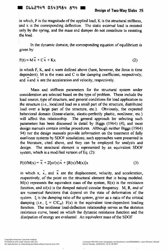
nbb2q4q 8q4 Design of Two-way Slabs 25
in which, F is the magnitude of the applied load, K is the structural stiffness, and x is the corresponding deflection. The static external load is resisted only by the spring, and the mass and damper do not contribute to resisting the load.
In the dynamic domain, the corresponding equation of equilibrium is given by:
in which F, K, and x were defined above (here, however, the force is time dependent). M is the mass and C is the damping coefficient, respectively; and and i are the acceleration and velocity, respectively.
Mass and stiffness parameters for the structural system under consideration are selected based on the type of problem. These include the load source, type of structure, and general conditions for load application to the structure (i.e., localized load on a small part of the structure, distributed load over a large part of the structure, etc.). Obviously, the expected behavioral domain (linear-elastic, elastic-perfectly plastic, nonlinear, etc.) will affect this relationship. The general approach for selecting such parameters has been discussed in detail by Biggs (1964) (4), and most design manuals contain similar procedures. Although neither Biggs (1964) 94) nor the design manuals provide information on the treatment of fully nonlinear systems by SDOF simulations, such approaches were presented in the literature, cited above, and they can be empioyed for analysis and design. The structural element is represented by an equivalent SDOF system, which is a modified version of Eq. (2):
F(t)/M(x) = ; + 25w'(x)x + [R(x)/M(x)]x (3)
in which x, i , and i are the displacement, velocity, and acceleration, respectively, of the point on the structural element that is being modeled. M(x) represents the equivalent mass of the system, R(x) is the resistance function, and o'(x) is the damped natural circular frequency. M, R, and w' are numerical functions that depend on the state of deformation of the system. 6 is the damping ratio of the system, given as a ratio of the critical damping (i.e., 6 = C/C,). F(x) is the equivalent time-dependent loading function. The nonlinear load-deflection relationship serves as the skeleton resistance curve, based on which the dynamic resistance function and the dissipation of energy are evaluated. An equivalent mass of the SDOF
Copyright American Concrete Institute Provided by IHS under license with ACI Licensee=AECOM User Geography and Business Line/5906698001, User=Elmorsi, Mostaf
Not for Resale, 10/05/2011 10:37:39 MDTNo reproduction or networking permitted without license from IHS
--`,``,,`,,`,,,,`,``,,,`,`,,,`,-`-`,,`,,`,`,,`---
m Obb2949 0543985 720 m 26 Woodson and Krauthammer
system is derived based on the deflected shape of the structural member. This approach bears similarities to previous methods, as described by Biggs (1964) (4) and as shown in design manuals, while the denvation of nonlinear resistance functions for various structural behavior mechanisms and other parameters was discussed by Krauthammer et al. (1990) (14). The effect of structural damping is usually small (5 is typically between 2% and 5%; however, this should be assessed based on the specific case under consideration). Therefore, the damping contribution, 2@1'(x) i may be ignored for many cases by setting 5 4 in Eq. (3).
The differences between the static and dynamic cases arise from the effects of inertia ( M i ) and damping ( C i ) that do not participate in the static response. Although the effect of structural damping is small, the inertia effect could be significant. Inertia may dominate the response whenever loading durations are much shorter than structural response times. Furthermore, unlike the static case where the magnitudes of force and stiffness determine directly the corresponding deflection, in the dynamic domain the response (ie., deflection, velocity, and acceleration) is obtained by solving the differential equation (2 or 3). Such solutions are usually obtained by employing a numerical approach, as discussed in Biggs (1964) and Clough and Penzien (1993) (4, 5). The system response will depend not only on the magnitude of the force, but also on the relationship between the dynamic characteristics of the force and the frequency characteristics of the structure. These are defined by the ratio IUM and the effect of damping. A detailed discussion of these issues is presented in Biggs (1964) (4), Clough and Penzien (1993) (5), and in Chapter 7 of Manual 42 (ASCE 1985) (2). The various design manuals (such as TM 5- 855-1, TM 5-1300, and Manual 42) contain dynamic response charts and tables that are based on SDOF considerations, and these can be used for design.
The differences between the approaches discussed by Biggs (1964) (4) and the various design manuals, cited above, and the modified approach proposed by Krauthammer (1984, 1986) (10, 12) and Krauthammer et al. (April i 986) ( i i ) include the use of a different stnictural resistance function. Instead of employing the classical concept for a resistance function (elastic, elastic-plastic, or plastic), the term R(x) was represented by the modified load-displacement relationship that included membrane effects, as described above. That relationship included membrane effects (compression and tension for one- or two-way slabs), and the influence of externally induced in-plane forces, shear effects, and strain rate effects on
Copyright American Concrete Institute Provided by IHS under license with ACI Licensee=AECOM User Geography and Business Line/5906698001, User=Elmorsi, Mostaf
Not for Resale, 10/05/2011 10:37:39 MDTNo reproduction or networking permitted without license from IHS
--`,``,,`,,`,,,,`,``,,,`,`,,,`,-`-`,,`,,`,`,,`---
W Obb2747 054378b 667 = Design of Two-way Slabs 27
the materials. Another modification extended the application of this approach to cases where the loads were localized rather than uniformly distributed.
When more advanced numerical approaches are considered important (e.g., fínite-element or finite-difference methods), one needs to ensure that the approach can represent membrane effects correctly. Certain types of elements may include tension membrane effects, but may lack the ability to exhibit compression membrane behavior. Others may introduce ‘‘numerical locking,” which is unrelated to the physical phenomenon of compression membrane behavior. Obviously, analysts and designers must understand the characteristics of the particular numerical tool they intend to use to ensure that the results would be interpreted correctly. Since a detailed discussion on such topics is beyond the scope of this paper, the reader can find further information in the literature (for example, Bathe 1996) (3).
Application for Analvsis and Design-The design of slabs in typical construction is often governed by serviceability requirements rather than by strength considerations. Therefore, the consideration of full compression and tension membrane enhancements may not be feasible. Since the peak compressive membrane capacity is expected to be associated with a central deflection of about OSh, it is quite possible that such conditions would meet AC1 deflection control requirements (AC1 1995) (i). Under certain conditions, considering some parts of membrane contribution could be advantageous. Furthermore, for special cases, the consideration of both compression and tension membrane effects could be justified. These issues need to be discussed further to illustrate such points of view.
Park and Gamble (1980) (7) showed that by considering compression membrane effects, designers could reduce the amount of steel in the slab to less than that required by the yield-line theory. However, additional steel had to be added to the supports to ensure sufficient restraining of the slab. Nevertheless, it was expected that more steel would be saved by considering compression membrane effects than that added to the supporting beams. However, designers would need to consider loading patterns on the floor slab to prevent overstressing the tie reinforcements in the supporting beams. In summary, one can include consideration of compressive membrane effects, but the detailing of steel in the support regions must be carefully examined to ensure that the enhanced slab capacity will not jeopardize the support integrity.
Copyright American Concrete Institute Provided by IHS under license with ACI Licensee=AECOM User Geography and Business Line/5906698001, User=Elmorsi, Mostaf
Not for Resale, 10/05/2011 10:37:39 MDTNo reproduction or networking permitted without license from IHS
--`,``,,`,,`,,,,`,``,,,`,`,,,`,-`-`,,`,,`,`,,`---
The consideration of membrane effects in special structures could be much more attractive. in fortifications, one must rely on every possible contribution to structural resistance for surviving severe loading environments. Often, under such conditions, survivability rather than serviceability may govern the required performance criteria. Obviously, a slab that can resist higher loads, even if it is associated with large deflections, could be very useful. Test data discussed by Krauthammer et al. (April 1986) (1 3) and Woodson (September 1994) (22) can be used to show such advantages. However, very careful attention must be given to shear reinforcement and to the support design to ensure that the slab can reach the corresponding resistance and deformation levels. Another type of structure that could benefit from membrane effect considerations would be a culvert. Again, based on operational needs for such structures, one may limit the design to only compressive membrane enhancement if deflections must be controlled. Otherwise, both compressive and tensile membrane effects could be considered. Besides the information presented by Park and Gamble (1980) (1 8), two recent examples of how compressive membrane enhancement could be utilized in design may illustrate this approach fwther.
Krauthammer et al. (1986) (13) adopted the approach in Park and Gambie (1 980) (1 8) for the redesign of reinforced concrete culverts. A one- barrel box culvert 40 ft long with a 1 2 4 by 1 2 4 opening was considered. Slab thicknesses were 11.5 in. for the roof, 12 in. for the floor, and 8 in. for the wails. The findings confirmed the expectations in Park and Gamble (1980) (18) as follows: First, in an existing slab, even small support stifniess can provide significant compressive membrane enhancements. When the ratio SEc was varied between 0.005 and 0.16 for the roof slab, the compressive membrane enhancements varied between 1.1 and 1.47. Second, when the slab was redesigned (the same steel was redistributed to accommodate compressive membrane action), its compressive membrane enhancement varied between 1.2 and 1.65. Third, a large SEc ratio would not ensure a much higher compressive membrane enhancement. When SEc was set to 50 in the original slab, the compressive membrane enhancement increased fiom 1.47 to 1.5. The slab was then checked for meeting serviceability requirements. It was found that cracking would be controlled by the given amount of steel, and the õ/h ratio varied between 0.5 and 0.2 for the given range of SEc ratios. For the roof slab, these ratios corresponded to deflections between 0.57 in. and 2.3 in. For a span of 144 in., these deflections correspond to deflection-to-span ratios ( 6 L ) in the
Copyright American Concrete Institute Provided by IHS under license with ACI Licensee=AECOM User Geography and Business Line/5906698001, User=Elmorsi, Mostaf
Not for Resale, 10/05/2011 10:37:39 MDTNo reproduction or networking permitted without license from IHS
--`,``,,`,,`,,,,`,``,,,`,`,,,`,-`-`,,`,,`,`,,`---
O b b Z ï 4 ï 0543988 43T = Design of Two-way Slabs 29
range between 0.004 and 0.016, which may be quite acceptable according to AC1 deflection control limits (AC1 1995) (i).
Meamarian et al. (November-December 1994) (15) continued the development of this approach by considering improved material and failure models and implemented them into an analysis and design computer code. In that approach, the general method presented by Park and Gamble (1 980) (1 8) was used to derive the ultimate load, deflections, and sectional forces. Then, the Modified Compression Field Theory (Vecchio and Collins, March through April 1986) (20) was used to compute the internal stresses, strains, crack angles, and total deflections. The proposed approach was used to simulate the behavior of 10 slabs for which test data were available. The average ratios of computed results to test data for axial force, moment, load, and deflection were 1.07, 1.07, 1 .O4 and 1 .O, respectively. However, the standard deviations for these comparisons were in the range between O. 13 and 0.38, showing that this approach will require additional attention before it could be used in support of design activities. Interestingly, for these slabs the compression membrane enhancement was estimated in the range between 1.7 and 2.9. Furthermore, this enhancement was important for thinner slabs with moderate amounts of steel (0.0071 p ~0.012)~ but it did not change for slabs with lower reinforcement ratios (e.g., p =0.005).
Connections and S u ~ w r t Conditions--It has been shown that the effect of the supports’ lateral restraint is very significant on the development of membrane enhancement in slabs. Although small magnitudes of support stiffness can introduce some membrane enhancement, one needs well- designed supports to enable the higher ranges of membrane enhancement. Attention to connection details is, therefore, an important factor that can ensure membrane enhancements. Reinforced concrete structures cannot develop their full capacity if their reinforcement details are inadequately designed. In connections, for example, the joint size is often limited by the size of the elements that fiame it. This restriction, along with poor reinforcement detailing, may create connections without sufficient capacity to develop the required strength of adjoining elements. Knee-joints are often the most difficult to design when continuity between adjoining members is required. The work by Nilsson (1973) (16) provided extensive insight into the behavior of joints under static loads, and on the relationships between performance and internal details. He showed that even slight changes in a connection detail had significant effects on the strength and behavior of the joint. Park and Paulay (1975) proposed the diagonal strut and the truss mechanisms to describe a joint’s internal
Copyright American Concrete Institute Provided by IHS under license with ACI Licensee=AECOM User Geography and Business Line/5906698001, User=Elmorsi, Mostaf
Not for Resale, 10/05/2011 10:37:39 MDTNo reproduction or networking permitted without license from IHS
--`,``,,`,,`,,,,`,``,,,`,`,,,`,-`-`,,`,,`,`,,`---
m Obb2949 0543989 376 m 30 Woodson and Krauthammer
resistance to the applied loads. The diagonal compression strut is obtained from the resultant of the vertical and horizontal compression stresses and shear stresses. When yielding in the flexural reinforcement occurs, the shear forces in the adjoining members are transferred to the joint core through the concrete compression zones in the beams and columns. The truss mechanism is formed with uniformly distributed diagonal compression, tensile stresses in the vertical and horizontal reinforcement, and the bond stresses acting along the beam and column exterior bars. These two mechanisms can transmit shearing forces from one face of a joint to the other, and their contributions were assumed to be additive.
The design approach for reinforced concrete connections by Park and Paulay (1975) was adopted in TM 5-1300 ( Department of the Army 1990) (9). Results from recent investigations of a blast containment structure by Krauthammer and Ku (accepted for publication) (14) and ûtani and Krauthammer (accepted for publication) (17) can be used to illustrate the importance of structural concrete detailing in connection regions. The findings showed that the location of the diagonal bar across the inner corner of the connection affected the joint's strength. The relationships between the maximum stress and the location of the diagonal bar, and/or its cross- sectional area, could be examined to produce design recommendations that can ensure a desired levei of performance. It was observed that the radial reinforcing bars across the connection (in the direction normal to the diagonal bar) affected the tensile stress in the diagonal bar at the inner corner of the connection. Furthermore, the diagonal compressive strut to resist the applied loads could be mobilized effectively by proper combination of radial and diagonal bars.
The strengthening of the joint regions by the diagonal bars caused the formation of plastic hinge regions in the walls near the ends of the diagonal bars. The relocation of the largest rotations from the support faces to the plastic hinge regions showed a shift of maximum moment and shear along the slabs. Examination of the stresses in the flexural bars along the slabs' planes of symmetry revealed that yielding and the maximum stresses in the interior flexural and tension bars were in the plastic hinge regions. Besides the damage to the flexural reinforcement, maximum shear stresses in the concrete and large tensile shock wave stresses also occurred in the plastic hinge regions. These stress patterns in both concrete and steel were in addition to the presence of direct in-plane tension in the slab (due to the expansion of the walls and roof caused by the interior explosion). They showed that excessive damage could occur at these regions if not properly designed. Current design procedures (in TM 5-1 300) do not address the
Copyright American Concrete Institute Provided by IHS under license with ACI Licensee=AECOM User Geography and Business Line/5906698001, User=Elmorsi, Mostaf
Not for Resale, 10/05/2011 10:37:39 MDTNo reproduction or networking permitted without license from IHS
--`,``,,`,,`,,,,`,``,,,`,`,,,`,-`-`,,`,,`,`,,`---
W O662949 0543990 O98 Design of Two-way Slabs 31
issue of plastic hinge regions, nor do they anticipate the location of maximum negative moment (negative yield-line location) to occur near the ends of the diagonal bars. Furthermore, the computation of structural capacity, in current design procedures, is based on the assumption of yield- line formation at the supports. Clearly, the shift in hinge location must be included to derive a more realistic structural capacity.
Using support rotations as a parameter that can indicate the extent of damage is customary, as defined in TM 5-1300. For the containment structure under consideration, it was required that such rotations would not exceed 2 degrees ( h i and Krauthammer, accepted for publication) (1 7). A support rotation (sometimes defined as the global rotation) is estimated by the slabs’ peak mid-span deflection divided by half the span length. The localized rotations computed in the hinge regions exceeded 12 degrees, and the global rotations exceeded 2 degrees. In this structure, the sidewall/roof connection, which had the largest local and global rotations, also had the largest diagonal and longitudinal stresses. This observation confirmed that the magnitudes of the local and global rotations provide a good indication of damage to the slab. Furthermore, these findings emphasize the need to address both local and global rotations in design approaches.
Conclusions
Research findings and design criteria developed for protective structures are available to assist engineers in the design of buildings to resist severe dynamic loads, particularly blast loads. Presently, no requirements for consideration of blast effects have been incorporated into general building design codes. It is clear that construction costs will be affected when the sûuctural resistance to blast effects is improved. Protective construction has led to practical and more economical design concepts and details; however, significant refinements of such approaches are required before they can be adopted in civilian construction.
Acknowledgements
The authors gratefully acknowledge permission from the OEce, Chief of Engineers to publish this paper.
Copyright American Concrete Institute Provided by IHS under license with ACI Licensee=AECOM User Geography and Business Line/5906698001, User=Elmorsi, Mostaf
Not for Resale, 10/05/2011 10:37:39 MDTNo reproduction or networking permitted without license from IHS
--`,``,,`,,`,,,,`,``,,,`,`,,,`,-`-`,,`,,`,`,,`---
Obb2949 0543993 T 2 4 W 32 Woodson and Krauthammer
References
American Concrete Institute (1 995), ?AC1 3 18-96, Building Code Requirements for Reinforced Concrete,? Detroit, Michigan. American Society of CiMi Engineers (1985) (out of print), ?Design of Structures to Resist Nuclear Weapons Effects,? Manual and Reports on Engineering Practice - No. 42, New York, New York.
Bathe, K.J. (1 996), ?Finite Element Procedures,? Prentice-Hall.
Biggs, John M. (1 964), Introduction to Structural Dvnamics, McGraw-Hill Book Company, New York.
Clough, *R. W., and Penzien, J. (1 993), ?Dynamics of Structures,? 2nd edition, McGraw-Hill.
Department of the Army (1 986), ?Fundamentals of Protective Design for Conventional Weapons,? TM 5-855-1 , Washington, DC.
Department of the Army (1 990), ?Response Limits and Shear Design for Conventional Weapons Resistant Slabs,? ETL 1 1 10-9-7, Washington, DC.
Department of the Army, the Navy, and the Air Force (1 990), ?Structures to Resist the Effects of Accidental Explosions,? Army TM 5-1 300, Navy NAVFAC P-397, Air Force AFR 88-22, Washington, DC.
Department of the Army (November 1990), ?Structures to Resist the Effects of Accidental Explosions,? TM5- 1300, Washington, DC.
Krauthammer, T: (March 1984), ?Shallow-Buried RC Box-Type Structures,?? Journal of Structural Engineering, ASCE, Vol 110, No. 3, pp 637-65.
Krauthammer, T., Bazos, N., and Holmquist, T.J. (April 1986), ?Modified SDOF Analysis of RC Box-type Structures,?? Journal of Structural Engineering, ASCE, Vol 112, No. 4, pp 726-744.
Krauthammer, T. (August 1986), ?A Numerical Gauge for Structural Assessment,? The Shock and Vibration Bulletin, Bulletin 56, Pari 1, pp 179-1 93.
Copyright American Concrete Institute Provided by IHS under license with ACI Licensee=AECOM User Geography and Business Line/5906698001, User=Elmorsi, Mostaf
Not for Resale, 10/05/2011 10:37:39 MDTNo reproduction or networking permitted without license from IHS
--`,``,,`,,`,,,,`,``,,,`,`,,,`,-`-`,,`,,`,`,,`---
0662949 0543992 Yb0 - Design of Two-way Slabs 33
Krauthammer, T., Hill, J.J., and Fares, T. (1986), “Enhancement of Membrane Action for Analysis and Design of Box Culverî~,~’ Transportation Research Record, No. 1087, pp 54-6 1 .
Krauthammer, T., and Ku, C.K. (accepted for publication, currently in print), “A Hybrid Computational Approach for the Analysis of Blast- Resistant Connections,” Computers and Structures.
Meamarian, N., Krauthammer, T., and OFallon, J. (November-December 1994), “Analysis and Design of One-way Laterally Restrained Structural Concrete Members,” Structural Journal. ACI, Vol 91, No. 6, pp 719-725.
Nilsson, I.H.E. (1 973), “Reinforcec‘ Concrete Corners and Joints Subjected to Bending Moment Design of Comers and Joints in Frame Structures,” Document D7: 1973, National Swedish Building Research. ûtani, R.K., and Krauthammer, T., (accepted for publication, currently in print), “Assessment of Reinforcing Details for Blast Containments Structures,” Structural Journal. ACI.
Roberts, E.H. (1969), “Load Carrying Capacity of Slab Strips Restrained Against Longitudinal Expansion,” Concrete, Vol 3, pp 369-378.
Vecchio, F.J., and Collins, M.P. (March-April 1986), “The Modified Compression Field Theory for Reinforced Concrete Elements Subjected to Shear,” Structural Journal. ACI, Vol 83, No. 2, pp 21 9-23 1 .
Wood, R.H. (1971), “How Slab Design has Developed in the Past, and What the Indications are for Future Development,” AC1 Publication SP-30.
Woodson, S.C., (September 1994), “Effect of Shear Reinforcement on the Large-Deflection Behavior of Reinforced Concrete Slabs,” Technical Report SL-94-18, US. Army Engineer Waterways Experiment Station.
Woodson, S.C. (November 1994), “Shear Reinforcement in Deep Slabs,” Technical Report SL-94-24, US. Army Engineer Waterways Experiment Station.
Copyright American Concrete Institute Provided by IHS under license with ACI Licensee=AECOM User Geography and Business Line/5906698001, User=Elmorsi, Mostaf
Not for Resale, 10/05/2011 10:37:39 MDTNo reproduction or networking permitted without license from IHS
--`,``,,`,,`,,,,`,``,,,`,`,,,`,-`-`,,`,,`,`,,`---
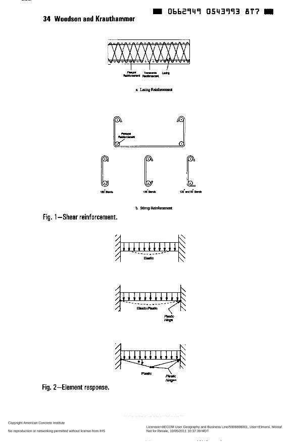
~
Ob62949 0543993 öT7 34 Woodson and Krauthammer
hSimpR' ' t
Fig. 1 -Shear reinforcement.
Fig. 2-Element response.
Copyright American Concrete Institute Provided by IHS under license with ACI Licensee=AECOM User Geography and Business Line/5906698001, User=Elmorsi, Mostaf
Not for Resale, 10/05/2011 10:37:39 MDTNo reproduction or networking permitted without license from IHS
--`,``,,`,,`,,,,`,``,,,`,`,,,`,-`-`,,`,,`,`,,`---

0bb2q4q 0543qq4 733 Design of Two-way Slabs 35
Compressive Tensile Membrane TransRion Membrane
Region Region Region
M e c t i o n
Fig. 3-Typical resistance function.
Copyright American Concrete Institute Provided by IHS under license with ACI Licensee=AECOM User Geography and Business Line/5906698001, User=Elmorsi, Mostaf
Not for Resale, 10/05/2011 10:37:39 MDTNo reproduction or networking permitted without license from IHS
--`,``,,`,,`,,,,`,``,,,`,`,,,`,-`-`,,`,,`,`,,`---
m Obb2949 0543995 h7T m
SP 183-3
Design for Punching Shear in Concrete
by S. Megally and A. Ghali
Design of connections of columns to flat slabs to ensure safety against punching failure is presented. The connections transfer shearing forces and moments between the columns and slabs. The objective is to cover the design procedure in most practical situations including: interior, edge and corner columns, prestressed and nonprestressed slabs, slabs with openings and slabs with shear reinforcement. The AC13 18-95 code requirements are adhered to where applicable. The designs are demonstrated by numerical examples. Design of shear reinforcement in raf? slabs, footings and walls subjected to concentrated horizontal forces is also discussed.
Keywords: columns (supports); connections; ductility; footings; prestressed concrete; punching shear; reinforced concrete; seismic design; shear strength; slabs; structural design
37 Copyright American Concrete Institute Provided by IHS under license with ACI Licensee=AECOM User Geography and Business Line/5906698001, User=Elmorsi, Mostaf
Not for Resale, 10/05/2011 10:37:39 MDTNo reproduction or networking permitted without license from IHS
--`,``,,`,,`,,,,`,``,,,`,`,,,`,-`-`,,`,,`,`,,`---
0662949 0543796 50b 38 Megally and Ghali
AC1 member Sami MegaUy is a post doctoral fellow in the Department of Civil Engineering at the University of Calgary, Alberta, Canada. He received a PhD degree from the University of Calgary in 1998 and a BSc degree from Ain- Shams University, Egypt, in 1988. His research interests are related to structurai analysis, the fuite element method and seismic design of reinforced concrete structures.
AC1 member Amin Ghaii is a professor of Civil Engineering at the University of Calgary, Alberta, Canada. He is the author of several papers and three books on the structural analysis and design of concrete structures. He is a member of ASCE, International Association of Bridges and Structures, and Council on Tall Buildings technical committees. He is also a member of AC1 Committees 344, Circular Prestressed Concrete Structures; and 43 5, Deflection of Concrete Building Structures; and a member of joint ACI-ASCE Committees 343, Concrete Bridge Design; and 421, Design of Reinforced Concrete Slabs.
INTRODUCTION
One of the most common floor systems is the flat plate. It provides architectural flexibility, more clear space, less building height, easier formwork and consequently shorter construction time. A serious problem that can arise in flat plates is brittle punching failure due to transfer of shearing forces and unbalanced moments between slabs and columns. Cracking due to shear occurs on inclined surfaces within the slab thickness. Thus up to or close to failure, the cracks are not visible on the slab surfaces. Occasionally, drop panels are used; this is an increase in the slab thickness over a small rectangular area above the supporting columns. Often more economical and more architecturally acceptable solution is to increase the strength and the ductility by use of shear reinforcement.
Requirements of ACI318-95 (1) building code for design of slabs against punching shear are reviewed. Design steps, following the code when applicable are presented. Prestressed and nonprestressed slabs and slabs with openings are covered. The design steps are demonstrated by numerical examples for interior, edge and corner columns. Reference is made to an available computer program which can be used for design. Design and arrangement of punching shear reinforcement in raft slabs, footings and walls is also discussed.
TYPES OF SHEAR REINFORCEMENT
The most commonly used type of shear reinforcement is vertical shear
Copyright American Concrete Institute Provided by IHS under license with ACI Licensee=AECOM User Geography and Business Line/5906698001, User=Elmorsi, Mostaf
Not for Resale, 10/05/2011 10:37:39 MDTNo reproduction or networking permitted without license from IHS
--`,``,,`,,`,,,,`,``,,,`,`,,,`,-`-`,,`,,`,`,,`---
0bb2949 0543997 4 4 2 Design of Two-way Slabs 39
reinforcing bars in the form of closed stirrups or shear studs (2) (Figs. 1 and 2). Vertical reinforcing bars crossing the surfaces of the crack (Fig. 3 ) will prevent their widening, provided that no slip occurs. A small amount of slip commonly occurs in the bends at the top and bottom of the vertical branch of a s t i p . The tensile force in the vertical branches of stimps can reach yield oniy in non- shallow members. In slabs, the vertical branch of a stirrup is relatively short; thus small slip causes large strain reduction, which does not allow the fiil1 yield strength of the stimp to be developed. For this reason the Canadian Standard (3) allows use of stimps oniy when the slab thickness is 2 12 in. (300 mm). The ACI318R (1) code commentary requires that stirrups be closed and be provided with heavy horizontal bars lodged in the stimp comers to assist in anchorage (Fig. la).
The shear studs detailed in Fig. 4 have anchor heads sufficiently large to develop the yield strength of the stud stem. Crushing of the concrete below the heads does not take place and no measurable slip occurs. This has been confirmed experimentally (4).
To be most effective, the shear reinforcing bars must be as tall as possible by being anchored close to the slab surfaces (see the left-hand side of Fig. 3) . A short shear reinforcing bar, as shown on the right-hand side of Fig. 3 , is not effective because the inclined cracks can pass above and below the bar without intersection. Figure 5 is a vertical section perpendicular to a stud strip showing the position of the Stud Shear Reinforcement (SSR) and the flexural reinforcement in the slab thickness. For most effectiveness of the SSR, its overall height should be as long as possible. Thus the overall length of the studs should not be less than the thickness of the slab minus the specified covers at top and bottom; a tolerance value, e.g. one half bar diameter of flexural reinforcement may be allowed.
Figure 6 represents load-deflection graphs for three slabs of thickness 5.9 in. The slabs differ only in the absence (5) or presence of conventional stirrups (6) or studs (5) as shear reinforcement. It can be seen that the beneficial effect of conventional stimps in such a thin slab is negligible. This represents partial justification of the Canadian Standard ( 3 ) provision that stirrups shall not be used in thin slabs.
ACI318-95 CODE REQUIREMENTS
Nonmestressed slabs
AC13 18-95 (1) requires that at a critical section at d/2 from column face (Fig. 7):
Copyright American Concrete Institute Provided by IHS under license with ACI Licensee=AECOM User Geography and Business Line/5906698001, User=Elmorsi, Mostaf
Not for Resale, 10/05/2011 10:37:39 MDTNo reproduction or networking permitted without license from IHS
--`,``,,`,,`,,,,`,``,,,`,`,,,`,-`-`,,`,,`,`,,`---
40 Megally and Ghali m 0hh2949 0543998 389 m
v u s 0 Vn (1) where vn is the nominal shear stress (Eqs. 4-6); is the strength reduction factor (4 = 0.85); vu is maximum shear stress caused by the transfer of a factored shearing force Vu and moments I& and & between the slab and column and acting at critical section centroid,
v u Y,Mu YY& Y+--- =-+-
u bod J, JY
where bo is length of perimeter of shear critical section; d is the distance fiom extreme compression fiber to centroid of longitudinal tension reinforcement; the subscripts x and y refer to centroidal axes in directions of both spans; (x, y) are coordinates of the point at which vu is maximum and J is a property of critical section “analogous to polar moment of inertia”. Figure 7 indicates the positive directions of x and y axes and the force Vu and moments M, and &; in this figure and others in this paper the arrows represent the directions of force and maments exerted by the column on the slab. Tw and TT are fiactions of the moments transferred by eccentricity of shear about the x and y axes, respectively: y , = l - 1
I + S J b ; T b ; (3)
AC13 18-95 (1) defines bi and bz, respectively, as widths of shear critical section measured in direction of the span for which moment is determined and perpendicular to it.
In absence of shear reinforcement, the code requires that the nominal shear stress of nonprestressed slabs be the smallest of (using Ib and in. units):
4 v,=v,= 2+- &
ß c
vn = v, = e + 2 & bo
v, = v, = 4 6
(4)
where vc is the nominal shear stress provided by concrete; ßc is ratio of long side to short side of column; fé is specified concrete compressive strength ; 4 = 40 for interior columns; 4 = 30 for edge columns and 4 = 20 for corner columns.
When vu > 4 vn ; slab thickness must be increased or shear reinforcement provided. When slab thickness is increased in the column vicinity, by means of
Copyright American Concrete Institute Provided by IHS under license with ACI Licensee=AECOM User Geography and Business Line/5906698001, User=Elmorsi, Mostaf
Not for Resale, 10/05/2011 10:37:39 MDTNo reproduction or networking permitted without license from IHS
--`,``,,`,,`,,,,`,``,,,`,`,,,`,-`-`,,`,,`,`,,`---
Design of Two-way Slabs 41 m 0662949 0543999 215 m
column capitals or drop panels, Eq. 1 must be satisfied at a critical section outside the thickened area of the slab. Aithough the stud shear reinforcement are shown (6) to be more effective than conventional stirrups because of the superiority of anchorage, AC13 18-95 (1) code does not distinguish between the two types of shear reinforcement, and expresses the nominal shear stress in presence of shear reinforcement as:
v, =v, +v, 56K (7)
v, = 2 6 (8)
where v, is nominal shear stress provided by shear reinforcement; Av is area of shear reinforcement within a distance s; fy is specified yield strength of shear reinforcement and s is spacing of shear reinforcement. The upper limit for s is 0.5 d. Shear reinforcement must be extended for a sufficient distance until the critical section outside the shear-reinforced zone (Fig. 8) satisfies Eq. 1 with V" =v, =2&
Other provisions for prestressed slabs and slabs with openings in the column vicinity will be discussed in following sections.
Prestressed Slabs
For prestressed slabs with no shear reinforcement, AC13 18-95 (i) replaces Eqs. 4 to 6 by:
where V, is the vertical component of ail effective prestress forces crossing the critical section; fF is average value of fF in two vertical slab sections in perpendicular directions, with fF being the compressive stress at section centroid after allowance for ail prestress losses; ß, is the smaller of 3.5 and [(% dh,) + 1.51. Eq. 10 can replace Eqs. 4 to 6 only if the following conditions are satisfied: (a) no portion of the cross section of the column shall be closer than 4 times the slab thickness to a discontinuous edge; (b) fcshall not be taken greater than 5000 psi and (c) fF in each direction shall not be less than 125 psi nor be taken greater than 500 psi.
Copyright American Concrete Institute Provided by IHS under license with ACI Licensee=AECOM User Geography and Business Line/5906698001, User=Elmorsi, Mostaf
Not for Resale, 10/05/2011 10:37:39 MDTNo reproduction or networking permitted without license from IHS
--`,``,,`,,`,,,,`,``,,,`,`,,,`,-`-`,,`,,`,`,,`---
Ob62949 0544000 635 M 42 Megally and Ghali
In thin slabs, it is difficult to control the slope of tendon profile at the point it crosses a critical section. Thus for practical consideration, the last term in Eq. 10 may be neglected, or V, reduced to account for the inaccuracy that can occur in the execution of the tendon profile.
Within the shear-reinforced zone, vn is to be calculated using the same equations as for nonprestressed slabs. Section 11.5.4.1 of ACI318-95 allows, for prestressed members, spacing of shear reinforcement, s to reach 3h/4 but not to exceed 24 in., where h is overall thickness of member. It is considered here that this limit is excessive in slabs and it is recommended that the spacing should not exceed 3d4. This is because the difference between d and h is more important in slabs than in beams and cracks could bypass the shear reinforcement as discussed earlier in conjunction with Fig. 3.
Slabs With Onenines
AC13 18-95 (1) requires that effect of openings on punching shear resistance of a slab-column connection must be considered when openings are located at a distance less than 10 times the slab thickness from the column, or when openings are located within the column strip. The effect of openings is taken into account by considering part of shear critical section to be ineffective. The ineffective part is that part of the critical section perimeter that is enclosed by straight lines projecting from the column centroid and tangent to the boundaries of the openings (see Example 4).
Reduction of the Coeficienty,
Section 13.5.3.3, introduced for the first time in ACI318-95 (i), allows, in design of slab-column connections without shear reinforcements, the use of values of h smaller than what is given by Eq. 3. This option is allowed oniy when the value of Vu is relatively small and when other conditions are satisfied. Discussions (7) of the new section, when it was proposed, indicated that this can lead to unsafe design. The present authors are of the same opinion; thus this option is not recommended here.
Desien for One-Wav Shear
Although this paper focuses on two-way (punching) shear design of slabs, one-
Copyright American Concrete Institute Provided by IHS under license with ACI Licensee=AECOM User Geography and Business Line/5906698001, User=Elmorsi, Mostaf
Not for Resale, 10/05/2011 10:37:39 MDTNo reproduction or networking permitted without license from IHS
--`,``,,`,,`,,,,`,``,,,`,`,,,`,-`-`,,`,,`,`,,`---
Obb2949 0544003 571 Design of Two-way Slabs 43
way shear resistance should also be checked. Figure 9a shows the one-way shear critical sections for interior and edge slab-column connections, according to the AC1 3 18-95 building code (1). The critical section extends in a plane across the entire slab width and is located at a distance d from the column face. Figure 9b shows the one-way shear critical section, according to the Canadian Standard (3), for comer slab-column connections in which case the critical section is a straight line of minimum length located not farther than d/2 fiom the column comer. If slab cantilevers extend beyond the face of the comer column, the length of the critical section may be extended into the cantilevered slab portion by a length not exceeding d.
The one-way shear check should satis@ the inequality:
where bo is the length of the critical section.
For the comer column in Fig. 9b, the angle 9 corresponding to the minimum b, should satis@
(c2+0.5dcosyr) i (c, +0.5dsin y) tanyr=3
This equation can be used to solve for + by trial. In the first trial @ = 4 9 , one additional trial will commoniy be sufficient.
It should be mentioned that the one-way shear critical section shown in Fig. 9b is not specified by the AC1 318-95 code (1). However, it is suggested here to use the section shown in Fig. 9b for one-way shear design of comer slab-column connections.
HIGHER ALLOWABLE VALUES FOR THE NOMINAL SHEAR STRESS AND SPACING OF SHEAR REINFORCEMENT
Shear reinforcement is not effective unless it is well anchored. ACI318R-95 code commentary (1) emphasizes the difficulty of anchorage of stirrups in slabs thinner than 10 in.; for such slabs, the commentary requires that stirrups should oniy be used if they are closed and enclose a longitudinal bar at each comer. The Canadian Standard CSAA23.3-94 (3) does not allow stirrups in slabs thinner than 12 in. (300 mm).
Copyright American Concrete Institute Provided by IHS under license with ACI Licensee=AECOM User Geography and Business Line/5906698001, User=Elmorsi, Mostaf
Not for Resale, 10/05/2011 10:37:39 MDTNo reproduction or networking permitted without license from IHS
--`,``,,`,,`,,,,`,``,,,`,`,,,`,-`-`,,`,,`,`,,`---

0bb2949 0544002 408 44 Megally and Ghali
Because of the superiority of anchorage of the stud shear reinforcement, justified by tests ($8-12), ACI421.1R-92 (2) suggests the following deviations fiom AC13 18 Code when shear studs are used: (a) the nominal shear stress, vn resisted by concrete and shear reinforcement (Eq. 7) can be as high as 8 6, instead of
6 & . This enables use of thinner slabs; (b) the upper limits for so and s can be based on the value of vu at the critical section at d 2 from column face: so s 0.5d and s s 0.75d when vu I @ I 6 6 (13.1)
so s 0.35d and s I 0.5d when vu 10 > 6 6 (13.2) where so is the distance between first peripheral line of studs and column face.
ACI421.1R-92 (2) considers a vertical branch of a stirrup to be less effective than a stud in controlling shear cracks because the stud stem is straight over its full length while the ends of the stirrup branch are curved, and the mechanical anchors at the stud ends ensure that the yield strength is available at ail sections of the stem; which is not the case with a vertical branch of a stirrup.
For the same reasons the Canadian standard CSA-A23.3-94 (3) allows, in presence of shear studs; a value of vc one-and-half times the allowable value when stirrups are employed. The same approach is adopted in the remainder of the paper; thus Eq. 8 is replaced by vc = 3 6 . The value of vc, the nominal shear stress provided by concrete in presence of shear reinforcement, represents the resistance of concrete after occurrence of shear cracks. Experiments indicate that studs are more efficient than conventional stirrups in controlling the width of inclined cracks. Thus, a higher value of vc should be expected. The value v, =3& is verified to be safe by experiments (10).
SHEAR REINFORCEMENT ARRANGEMENTS
Figures 10 and 11 show typical arrangements of stud shear reinforcement at rectangular and circular columns, respectively. Each group of studs on a l i e perpendicular to column face are welded to a steel strip, Fig. 2. ACI421.1R-92 (2) recommends that, in direction parallel to column face, the maximum distance, g between the steel strips be less than 2d. This limitation is to ensure that the studs confine the concrete and prevent widening of shear cracks over the perimeter of the critical section.
When stinups are used, they should be placed in rows parallel to the column t h e
Copyright American Concrete Institute Provided by IHS under license with ACI Licensee=AECOM User Geography and Business Line/5906698001, User=Elmorsi, Mostaf
Not for Resale, 10/05/2011 10:37:39 MDTNo reproduction or networking permitted without license from IHS
--`,``,,`,,`,,,,`,``,,,`,`,,,`,-`-`,,`,,`,`,,`---
m Obb2949 O544003 344 W Design of Two-way Slabs 45
(Fig. 1). In direction parallel to the column faces, the distance g between stirrup legs (Fig. la) should satis@ the requirement g 5 2d; or because stirrups are less effective than shear studs, a more restrictive limit should apply.
THE PARAMETER J
The vertical shear stress vu calculated by Eq. 2 has vertical resultant component = Vu; but has resultant moment components slightly smaller than Ya M, and Y, &. Replacing J, and J, by the moments of inertia I, and I,, respectively gives linearly varying stress distribution, whose resultants are exactly equal to V, Yw M, and Y, Mu,. Thus Eq. 2 becomes:
This equation satisfies the linear distribution required in Section 11.12.6.2 of ACI318-95 (1). The equation satisfies equilibrium only when x and y are centroidal principal axes (e.g. Figs. 7% b and 8% b).
The symbols J, and J,, defined by the code ( i ) as section properties "analogous to polar moment of inertia", have no known meaning in mechanics. For this reason, calculation of the two parameters is ambiguous when the critical section is irregular (e.g. slabs with openings and critical sections outside shear-reinforced zone). Ambiguity of the symbols J, and Jy is avoided by replacing them by the well-known second moments of area I, and I,.
THE COEFFICIENT Yv
The empirical Eq. 3 adopted by AC13 18-95 is shown by numerous experiments to be satisfactory for interior columns in which the critical section, at d/2 from column faces, has the shape of the perimeter of a closed rectangle. At the same location, the critical section for edge and comer columns has three or two sides, respectively (Fig. 7b and c). Outside the shear-reinforced zone, the critical section follows the perimeter of a closed or open polygon, whose sides are not all parallel to a column face (Fig. 8). Problems arise (13) when the empirical Eq. 3 is employed for comer and edge columns.
Elgabry and Ghali (14) showed by numerous finite element analyses that Eq. 3 does not apply for all cases and for all critical sections. AC1 3 18-95 code Eq. 3 proved to be satisfactory for interior columns only, but for other cases the finite eiemttnt resuits stisweu mat the same quation Gannat be applied. Elgabiry and
Copyright American Concrete Institute Provided by IHS under license with ACI Licensee=AECOM User Geography and Business Line/5906698001, User=Elmorsi, Mostaf
Not for Resale, 10/05/2011 10:37:39 MDTNo reproduction or networking permitted without license from IHS
--`,``,,`,,`,,,,`,``,,,`,`,,,`,-`-`,,`,,`,`,,`---
46 Megally and Ghali
~~
= 0662949 O544004 280
Ghaii (14) supplemented the AC1 code equation to give a set of equations applicable for ail cases (Fig. 12):
At interior columns: 1 I y , = l -
1 + $ =
1 y,=1- , + S a
At edge columns: y, = same as Eq. 15
e when 2 4 . 2 , y, = O 1 y,=1-
1 + A J m e, 3
At comer columns: y, = 0.4 y, = same as Eq. 18
where e , and fly are projections of the critical section on principal axes x and y respectively. The safes of design using the above equations has been verified using published experimental results (14).
DESIGN PROCEDURE
The data required for design of slab-column connections are: d, CI, CZ, V,,, b and and fi (Fig. 7). It is required to determine whether d is sufficient for safety against punching without the use of shear reinforcement and if not, design the necessary shear relliforcement. The steps of design are: Step 1: Replace V, & and at column centroid, O by the statical equivalents V, M, and & at the centroid of the critical section at d/2 fiom column face (Fig. 7):
where xo and yo are coordinates of the column centroid. Appropriate signs for the force and moments must be used; the positive sign convention is indicated in Fig. 7. Step 2: Calculate vu by Eq. 14 which is repeated here:
M,=M-+VUyo M,=M-+VUXO (21)
Copyright American Concrete Institute Provided by IHS under license with ACI Licensee=AECOM User Geography and Business Line/5906698001, User=Elmorsi, Mostaf
Not for Resale, 10/05/2011 10:37:39 MDTNo reproduction or networking permitted without license from IHS
--`,``,,`,,`,,,,`,``,,,`,`,,,`,-`-`,,`,,`,`,,`---
m Ob62949 0544005 LL7 m Design of Two-way Slabs 47
Vu Y Mu y I VU=- +" bo d 1, IY
x and y are coordinates of the point at which the shear stress is maximum, I, and I, are second moment of area of the critical section about centroidal principal axes x and y. When x and y are centroidal nonprincipal axes replace Eq. 14 by Eq. A. 1. (see Appendix A).
Properties of the critical section maybe determined with the help of Appendix B; Yw and TT are to be determined as functions of the ratio (PJQy); see Eqs. 15-20. Step 3: If vu 2 (Pvn (given by Eqs. 4-6), no shear reinforcement is required. If (vu/@) > vn limit, d must be increased; where vn limit = 6 6 or 8 &- when stirrups or studs are used as shear reinforcement, respectively. When vn < vu/@ s vn lit,
go to step 4. Step 4: Select Av and s such that Eq. 1 is satisfied. When conventional stirrups are used, Vn is determined using Eqs. 7 to 9. If stud shear reinforcement is used, the nominal shear stress becomes: V" - - vc + vs -
with (22)
v c = 3 A (23) and vs is given by Eq. 9. Step 5: Extend the shear-reinforced zone to chosen distances from column. Repeat Steps 1 and 2 for a critical section at dí2 outside the outermost peripheral line of shear reinforcement (Fig. 8). If vu s 2 @ 6 , extension of shear reinforcement is sufficient; if not, extend the shear reinforcement farther away from column and repeat steps 1 and 2 until the requirement is satisfied.
COMPUTER PROGRAM STDESIGN
The design procedure presented in this paper can be performed using the available computer program STDESIGN (1 S), for use with microcomputers.
SHEAR REINFORCEMENT M FOUNDATIONS AND WALLS
Shear reinforcement can be used and designed using the above equations to resist punching in raíl foundations, footings and in wails subjected to concentrated horizontal forces (e.g. offshore structures). Figure 13a represents the arrangement of shear studs in the vicinity of a column in a raíl foundation;
Copyright American Concrete Institute Provided by IHS under license with ACI Licensee=AECOM User Geography and Business Line/5906698001, User=Elmorsi, Mostaf
Not for Resale, 10/05/2011 10:37:39 MDTNo reproduction or networking permitted without license from IHS
--`,``,,`,,`,,,,`,``,,,`,`,,,`,-`-`,,`,,`,`,,`---
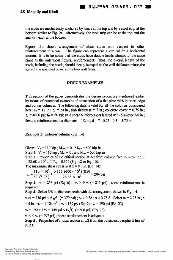
0bb2949 054400b 053 48 Megally and Ghali
the studs are mechanically anchored by heads at the top and by a steel strip at the bottom S i a r to Fig. 2a. Aiternatively, the steel strip can be at the top and the anchor heads at the bottom.
Figure 13b shows arrangement of shear studs with respect to other reinforcement in a wall. The figure can represent a vertical or a horizontal section. It is to be noted that the studs have double heads situated in the same plane as the outermost flexural reinforcement. Thus, the overall length of the studs, including the heads, should ideally be equal to the wall thickness minus the sum of the specified cover at the two wall faces.
DESIGN EXAMPLES
This section of the paper demonstrates the design procedure mentioned earlier by means of numerical examples of connection of a flat plate with interior, edge and comer columns. The following data is valid for all the columns considered here: CI = 12 in.; cz = 20 in.; slab thickness = 7 in.; concrete cover = 0.75 in.; f i = 4000 psi; fY = 50 ksi; stud shear reinforcement is used with diameter 3/8 in.; flexural reinforcement bar diameter = 1/2 in.; d = 7 - 0.75 - 0.5 = 5.75 in.
Examde 1: Interior column (Fig. 14)
Given: Vu = 110 kip ; k = O ; M,,,o = 600 kip-in. Step 1: Vu = 110 kip ; L= O ; and M,,,,= 600 kip-in. Step 2: Properties of the critical section at d/2 from column face: bo = 87 in.; Iy = 28.68 x io' in.4; 'Y, = 0.356 (Fig. 12 or Eq. 16). The maximum shear stress is at x = 8.9 in. (Eq. 14):
110 x lo3 + 0.356 ( 6 0 0 ~ 103)(8.9) 87 (5.75) 28.68 x lo3
= 286 psi. vu =
Step 3: vn = 253 psi (Eq. 6) ; vu > 0 vn (= 215 psi) ; shear reinforcement is required. Step 4: Select 3/8 in. diameter studs with the arrangement shown in Fig. 14. vJ0 = 336 psi < 6 6 (= 379 psi) ; so s 0.5d ; s s 0.75 d. Select so = 2.25 in.; s = 4 in.; A, = 1.104 in'. ; v, = 159 psi (Eq. 9) ; vc = 190 psi (Eq, 23). vn = 190 + 159 = 349 psi < 8 (= 506 psi) (Eq. 22). vu < 0 vn (= 297 psi) ; shear reinforcement is adequate. Step 5 : Properties of critical section at d/2 from the outermost peripheral line of studs:
Copyright American Concrete Institute Provided by IHS under license with ACI Licensee=AECOM User Geography and Business Line/5906698001, User=Elmorsi, Mostaf
Not for Resale, 10/05/2011 10:37:39 MDTNo reproduction or networking permitted without license from IHS
--`,``,,`,,`,,,,`,``,,,`,`,,,`,-`-`,,`,,`,`,,`---
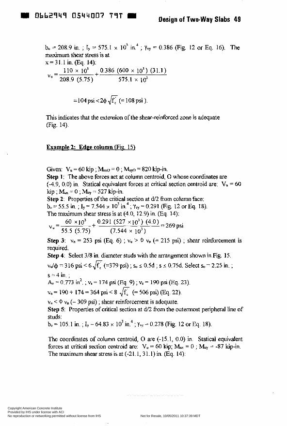
m 0662949 0544007 T 9 T Design of Two-way Slabs 49
bo = 208.9 in. ; I, = 575.1 x lo3 in.4 ; Yq = 0.386 (Fig. 12 or Eq. 16). The maximum shear stress is at x = 31.1 in. (Eq. 14):
- 110 x IO3 +0.386 (600 x io3) (31 .1 ) 208.9 (5.75) 575.1 x 10' vu -
= 104psi <24 &- (= 108 psi ).
This indicates that the extension of the shear-reinforced zone is adequate (Fig. 14).
Examde 2 Edge column Wig. 15)
Given: Vu = 60 kip ; & = O ; Mm = 820 kip-in. Step 1: The above forces act at column centroid, O whose coordinates are (-4.9, 0.0) in. Statical equivalent forces at critical section centroid are: Vu = 60 kip ; M, = O ; Step 2: Properties of the critical section at d/2 from column face: bo = 55.5 in. ; Iy = 7.544 x IO3 The maximum shear stress is at (4.0, 12.9) in. (Eq. 14):
= 527 kip-in.
; Yq = 0.291 (Fig. 12 or Eq. 18).
Step 3: vn = 253 psi (Eq. 6) ; vu > (P Vn (= 215 psi) ; shear reinforcement is required. Step 4: Select 3/8 in. diameter studs with the arrangement shown in Fig. 15. v./+ = 3 16 psi < 6 f i (=379 psi) ; so 5 0.5d ; s 5 0.75d. Select so = 2.25 in. ; s = 4 in. ; A, = 0.773 in2. ; vs = 174 psi (Eq. 9) ; vc = 190 psi (Eq. 23) vn = 190 -t 174 = 364 psi < 8 JfF (= 506 psi) (Eq. 22). vu < (P vn (= 309 psi) ; shear reinforcement is adequate. Step 5: Properties of critical section at dí2 from the outermost peripheral line of studs: bo = 105.1 in. ; Iy = 64.83 x lo3 in.4 ; Ys = 0.278 (Fig. 12 or Eq. 18).
The coordinates of column centroid, O are (-15.1, 0.0) in. Statical equivalent forces at critical section centroid are: Vu = 60 kip; M, = O ; Muy = -87 kip-in. Themaximumshear stressisat (-21.1, 31.1)in. (Eq. 14):
Copyright American Concrete Institute Provided by IHS under license with ACI Licensee=AECOM User Geography and Business Line/5906698001, User=Elmorsi, Mostaf
Not for Resale, 10/05/2011 10:37:39 MDTNo reproduction or networking permitted without license from IHS
--`,``,,`,,`,,,,`,``,,,`,`,,,`,-`-`,,`,,`,`,,`---
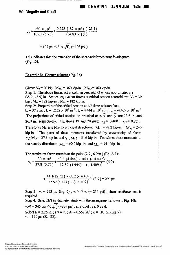
m Obb2949 0544008 92b m 50 Megally and Ghali
60 x io’ 0.278 (-87 x l d ) (-21.1) + v‘=105.1 (5.75) (64.83 x lo3)
This indicates that the extension of the shear-reinforced zone is adequate (Fig. 15).
Examde 3: Corner column (Fig. 16)
Given: Vu = 30 kip ; b = 360 kip-in. ; & = 360 kip-in. Step 1: The above forces act at column centroid, O whose coordinates are (-5.9 , -5.9) in. Statical equivalent forces at critical section centroid are: V. = 30 kip ; M, = 182 kip-in. ; h.z, = 182 kip-in. Step 2: Properties of the critical section at di2 from column face: bo = 37.8 in. ; h = 12.52 x IO’ in.4 ; Iy = 4.444 x lo3 in4 ; I, = -4.409 x 10 in. . The projections of critical section on principal axes and i are 13.6 in. and 26.9 in., respectively. Equations 19 and 20 give: yvx = 0.400 ; y,,; = 0.269. Transform & and U, to principal directions: Mu; = 93.2 kip-in. ; Mu;= 240 kip-in. The parts of these moments transferred by eccentricity of shear: y,,; Mu;= 37.3 kip-in. and yVy M ~ ; = 64.6 kip-in. Transform these moments to the x and y drections: M, = 60.2 kip- i n . and Muy = 44.1 kip- in.
3 4
The maximum shear stress is at the point (2.9 ,6.9 in.) (Eq. A. 1): 30 x lo3 + 60.2 (4.444) - 44.1 (- 4.409)
V” = (6.91 37.8 (5.75) 12.52 (4.444) - (- 4.409)’
44.1(12.52) - 60.2(- 4.409) + (2.9)= 293 psi 12.52(4.444) - (- 4.409)’
Step 3: Vn = 253 psi (Eq. 6) ; vu > @ Vn (= 215 psi) ; shear reinforcement is required. Step 4: Select 3/8 in. diameter studs with the arrangement shown in Fig. 16b. vJ@ = 345 psi < 6 6 (=379 psi) ; so I 0.5d ; s I 0.75 d. Select so = 2.25 in. ; s = 4 in. ;A,= 0.552 in.*; vs = 183 psi (Eq. 9). vc = 190 psi @q. 23).
Copyright American Concrete Institute Provided by IHS under license with ACI Licensee=AECOM User Geography and Business Line/5906698001, User=Elmorsi, Mostaf
Not for Resale, 10/05/2011 10:37:39 MDTNo reproduction or networking permitted without license from IHS
--`,``,,`,,`,,,,`,``,,,`,`,,,`,-`-`,,`,,`,`,,`---
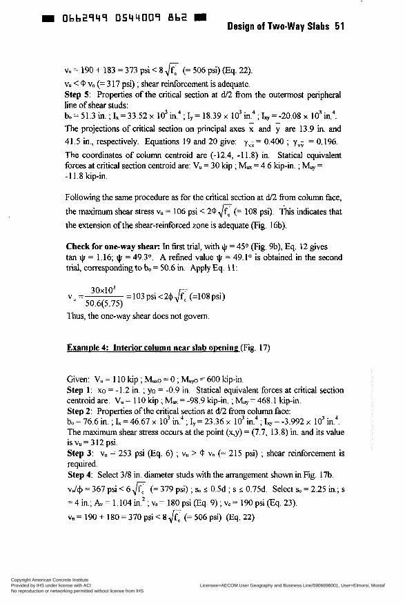
Ob62949 0544009 8b2 Design of Two-way Slabs 51
Vn = 190 + 183 = 373 psi < 8 .IfF (= 506 psi) (Eq. 22). vu < Q Vn (= 3 17 psi) ; shear reinforcement is adequate. Step 5: Properties of the critical section at d/2 fi-om the outermost peripheral line of shear studs: bo = 51.3 in. ; k = 33.52 x lo3 in.* ; Iy = 18.39 x lo3 in.4 ; S = -20.08 x lo3 in.4. The projections of critical section on principal axes and y are 13.9 in. and 41.5 in., respectively. Equations 19 and 20 give: y,;= 0.400 ; y,, = 0.196. The coordinates of column centroid are (-12.4, -11.8) in. Statical equivalent forces at critical section centroid are: Vu = 30 kip ; M, = 4.6 kip-in. ; Muy = -1 1.8 kip-in.
Following the same procedure as for the critical section at d/2 from column face, the maximum shear stress vu = 106 psi < 2 Q K (= 108 psi). This indicates that the extension of the shear-reinforced zone is adequate (Fig. 16b)
Check for one-way shear: In first trial, with * = 450 (Fig. 9b), Eq. 12 gives tan $ = 1.16; $I = 49.3". A refined value + = 49.1° is obtained in the second triai, corresponding to bo = 50.6 in. Apply Eq. 11:
3Ox1O3 5 O. 6( 5.75)
v, = = 103 psi <2$ (=lo8 psi)
Thus, the one-way shear does not govern.
Example 4: Interior column near slab oneninq(Fig. 17)
Given: Vu = 110 kip ; M d = O ; M,,,o = 600 kip-in. Step 1: xo = -1.2 in. ; yo = -0.9 in. Statical equivalent forces at critical section centroid are: Vu = 110 kip ; M, = -98.9 kip-in. ; Muy = 468.1 kip-in. Step 2: Properties of the critical section at d/2 fi-om column face: bo=76.6in.;I,=46.67x 103in.4;I,=23.36x 103in.4;I,=-3.992x 103in. . The maximum shear stress occurs at the point (x,y) = (7.7, 13.8) in. and its value is vu = 3 12 psi. Step 3: Vn = 253 psi (Eq. 6) ; vu > @ Vn (= 215 psi) ; shear reinforcement is required. Step 4: Select 3/8 in. diameter studs with the arrangement shown in Fig. 17b. vJ+ = 367 psi < 6& (= 379 psi) ; sa s 0.5d ; s 2 0.75d. Select so = 2.25 in.; s = 4 in.; A, = 1.104 in.* ; vs = 180 psi (Eq. 9) ; vc = 190 psi (Eq. 23).
4
Vn = 190 + 180 = 370 psi < 8 Jrc (= 506 psi) (Eq. 22)
Copyright American Concrete Institute Provided by IHS under license with ACI Licensee=AECOM User Geography and Business Line/5906698001, User=Elmorsi, Mostaf
Not for Resale, 10/05/2011 10:37:39 MDTNo reproduction or networking permitted without license from IHS
--`,``,,`,,`,,,,`,``,,,`,`,,,`,-`-`,,`,,`,`,,`---
52 Megally and Ghali
~
D 0bb2949 0544010 584
vu < GJ vn (= 3 15 psi) ; shear reinforcement is adequate. Step 5: Properties of the criti" 4'"" at d 2 from coFmnq face: bo = 204.5 in. ; I, = 843.6 x 10 in. ; Iy = 635.0 x 10 in. ; b = -80.99 x lo3 in4. The principal axes and the projections of the critical sections on the principal axes are shown in Fig. 1% ; y";= 0.408 ; yVy = 0.392 (Eqs. 15 and 16). The maximum shear stress occurs at (%y) = (3.4, -41.3) in. and its value =
98 psi < 29 6 (= 108 psi), indicating that the extension of the shear-reinforced zone is sufficient (Fig. 1%).
CONCLUSIONS
Brittle punching shear failure must be avoided in slabs, rafts or wails. The punching can be caused by large concentrated forces or the transfer of vertical shear and moments between slab and columns. A complete design procedure which satisfies the requirements of AC13 18-95 is applied. Where necessary, in situations not covered by the code, equations based on research are used. Numencal design examples covering most of the practical cases are presented.
ACKNOWLEDGEMENT
This study was funded by a grant from the Natural Sciences and Engineering Research Council of Canada which is gratefully acknowledged.
REFERENCES
1. AC1 Committee 318, Building C d Requirements for Structural Concrete (ACI318-95) and î o m m e n t q ACI318R-95, American Concrete Institute, Michigan, 1995,368 pp.
2. AC1 Committee 421, Shear Reinforcement for Slabs, American - Concrete Institute, ACI421.1R-92, February 1993, 1 1 pp.
3. Canadian Standards Association, Design of Concrete Structures (C'SA- A23.3-94, December 1994, 199 pp.
4. Eligehausen, R., Bericht über Zuguersuche mit Deha Kopfbolzen, (Report on Puil Tests on Deha Anchor Bolts), Institut fur Werkstoffe in
Copyright American Concrete Institute Provided by IHS under license with ACI Licensee=AECOM User Geography and Business Line/5906698001, User=Elmorsi, Mostaf
Not for Resale, 10/05/2011 10:37:39 MDTNo reproduction or networking permitted without license from IHS
--`,``,,`,,`,,,,`,``,,,`,`,,,`,-`-`,,`,,`,`,,`---
Design of Two-way Slabs 53 m Obb2949 0544011 410 - Bauwesen, University of Stuttgart, Report Nr. DE003/01-96132, September 1996 (Research carried out on behalf of Deha Ankersysteme GMBH & Co. KG, Gross-Gerau).
5.
6.
7.
8.
9.
10.
11.
12.
13.
14.
Mokhtar, A.S., Ghali, A., and Dilger, W.H., "Stud Shear Reinforcement for Flat Concrete Plates", ACI Slructural Journal, Proceedings, V. 82, No. 5, September-October 1985, pp. 676-683.
Ghali, A., and Hammill, N.L., "Eff'ectiveness of Shear Reinforcement in Slabs", Concrete International, V. 14, No. 1, January 1992, pp. 60-65.
"Discussion of Proposed Revisions to Building Code Requirements for Reinforced Concrete (AC13 18-89) (Revised 1992) and Commentary (AC13 18R-89) (Revised 1992)", Concrete International, V. 17, No. 7, July 1995, see contribution by Dilger, W., and Sherif, A., pp. 70-73; see also contribution by Ghali, A., and Megally, S., pp. 77-82.
Dilger, W.H., and Ghali, A., "Shear Reinforcement for Concrete Slabs", Proceedings, ASCE, V. 107, ST12, December 1981, pp. 2403-2420.
Andrä, H.P., "Strength of Flat Slabs Reinforced with Stud Rails in the Vicinity of the Supports (Zum Tragverhalten von Flachdecken mit Dubelliesten - Bewchruing im Auflogerbereich)", Beton-und Stahlbetonbau, Berlin, V. 76, No. 3, March 1981, pp. 53-57, and No. 4, April 1981, pp. 100-104.
Elgabry, A.A., and Ghali, A., "Tests on Concrete Slab-Column Connections with Stud Shear Reinforcement Subjected to Shear- Moment Transfer", ACI Slructural Journal, Proceedings, V. 84, No. 5, September-October 1987, pp. 433-442.
Mortin, J., and Ghali, A., "Connection of Flat Plates to Edge Columns", ACIStructural Jmmal, V. 88, No. 2, March-April 1991, pp. 191-198.
Dilger, W.H., and Shatila, M., "Shear Strength of Prestressed Concrete Edge Slab-Column Connections With and Without Stud Shear Reinforcement", Candian Journal of Civil Engineering, V. 16, No. 6, 1989, pp. 807-819.
Elgabry, A.A., and Ghali, A., "Transfer of Moments Between Columns and Slabs: Proposed Code Revisions", ACI Strzrctural Journal, V. 93, No. 1, January-February 1996, pp. 56-61.
Elgabry, A.A., and Ghali, A., "Moment Transfer by Shear in Slab- Column Connections", ACI Strircttrral Journal, V. 93, No. 2, March -
Copyright American Concrete Institute Provided by IHS under license with ACI Licensee=AECOM User Geography and Business Line/5906698001, User=Elmorsi, Mostaf
Not for Resale, 10/05/2011 10:37:39 MDTNo reproduction or networking permitted without license from IHS
--`,``,,`,,`,,,,`,``,,,`,`,,,`,-`-`,,`,,`,`,,`---
= 0662949 0544032 357 54 Megally and Ghali
Apd 1996, pp. 187-196,
15. Ghali: A. (Revised by N. Hammill, 1995), Computer Program SïDESZGN, Decon, 35 Devon Road, Brampton, Ontario, Canada L6T 5B6.
NOTATIONS
cross-sectional area of shear reinforcement on a line parallel to the perimeter of the column width of the critical section for shear, at d/2 from column face, measured in the direction of the span for which moments are determined width of the critical section for shear, at d/2 from column face, measured in the direction perpendicular to bi length of perimeter of critical section dimensions of column measured in the two span directions effective depth of slab specified compressive strength of concrete compressive stress in concrete (after allowance for all prestress losses) at centroid of cross section resisting extemaiiy applied loads specified yield strength of shear reinforcement spacing between a stirrup vertical branches or shear studs in a direction parallel to column face slab thickness second moments of area of critical section about axes x and y, respectively product of inertia of area of critical section about axes x and y property of the shear critical section defined by AC13 18-95 code as "analogous to the polar moment of inertia" projections of critical section on principal axes x and y, respectively = factored unbalanced moments transferred between the
slab and the column about axes x and y, respectively, at critical section centroid part of moments transferred by eccentricity of shear at slab-column connections factored unbalanced moments transferred between the slab and the column about axes x and y, respectively, at column centroid
=
=
spacing between peripheral lines of shear reinforcement
Copyright American Concrete Institute Provided by IHS under license with ACI Licensee=AECOM User Geography and Business Line/5906698001, User=Elmorsi, Mostaf
Not for Resale, 10/05/2011 10:37:39 MDTNo reproduction or networking permitted without license from IHS
--`,``,,`,,`,,,,`,``,,,`,`,,,`,-`-`,,`,,`,`,,`---
m Oh62949
so
Ve
Vn
VO
VP
vs vu VU X>Y
4 ß c
ßP Y"
O
4 iIr
0544013 293 9 Design of Two-way Slabs 55
spacing between the first peripheral line of shear reinforcement and column face nominal shear stress provided by concrete in presence of shear reinforcement nominal shear stress of critical section nominal capacity of a slab-column connection with no shear reinforcement in absence of unbalanced moment vertical component of effective prestress forces crossing the critical section nominal shear stress provided by shear reinforcement maximum shear stress at critical section due to applied forces applied shearing force at failure coordinates of point of maximum shear stress in critical section with respect to centroidal axes x and y factor which adjusts ve for support type ratio of long side to short side of concentrated load or reaction area constant used to compute vc in prestressed slabs fiaction of unbalanced moment transferred by eccentricity of shear at slab-column connections angle of inclination of principal axes x and y with respect to the centroidal axes x and y, respectively strength reduction factor = 0.85 angle of inclination of critical section for one-way shear with respect to the slab free edge
- -
CONVERSION FACTORS
1 in. = 25.4 mm 1 fi = 0.3048m 1 kip = 4.448kN
1 fi-kip = 1.356 kN-m 1 psi = 6.89 x 10⁵MPa
K , p s i = 0.083&,MPa
APPENDIX A: EQUATION FOR vu WHEN x AND y ARE CENTROIDAL NONPRINCIPAL AXES
The following equation applies when x and y are any two orthogonal centroidai
Copyright American Concrete Institute Provided by IHS under license with ACI Licensee=AECOM User Geography and Business Line/5906698001, User=Elmorsi, Mostaf
Not for Resale, 10/05/2011 10:37:39 MDTNo reproduction or networking permitted without license from IHS
--`,``,,`,,`,,,,`,``,,,`,`,,,`,-`-`,,`,,`,`,,`---

56 Megally and Ghali
axes:
~ ~~ ~
0bb2949 0544034 32T
Ed, I, Iy - - E v I v ] y + [ ~ v l x 1; I, I, - - M.I,] 1; X
where E, and M, are parts of moments transferred by eccentricity of shear at slab-column connections and = x y d A is the product of inertia of area of critical section about axes x and y (see Appendix B).
When x and y are principal axes Iy = O and Eq. A. 1 reduces to Eq. 14.
APPENDIX B: PROPERTIES OF SHEAR CRITICAL SECTION
In general, the periphery of shear critical section is composed of straight segments. The values of bo, I,, I, and I, of the critical section may be determined by summation of the contributions of straight segments:
m m m m
bo = x t, ; I, = CI,, ; I, = I,, : I, = I,, i = l i = l i=l i=l
where m is the total number of segments and i refers to the i th segment. A typical straight segment AB is shown in Fig. B.1; its contributions to b% L,,, I, and I, may be calculated by:
where d is effective depth ; (XA, YA) and (xb YB) are the coordinates of the segment ends A and B.
The angle 8 between the principal i axis and the x axis is given by (Fig. 16 ; the positive sign convention for 8 is indicated): tan28=- 2 L/(I, - I,) 03.6)
Copyright American Concrete Institute Provided by IHS under license with ACI Licensee=AECOM User Geography and Business Line/5906698001, User=Elmorsi, Mostaf
Not for Resale, 10/05/2011 10:37:39 MDTNo reproduction or networking permitted without license from IHS
--`,``,,`,,`,,,,`,``,,,`,`,,,`,-`-`,,`,,`,`,,`---
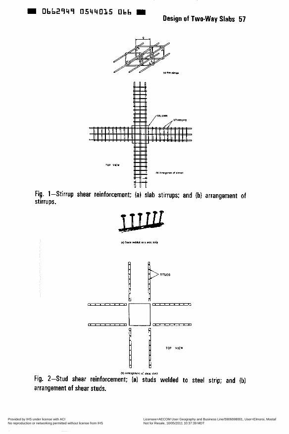
0662949 0544015 Obb Design of Two-way Slabs 57
Fig. l-Stirrup shear reinforcement; (a) slab stirrups; and (b) arrangement of stirrups.
f . . . . . . . . I
. . . . . . . . .
j p-ruos I I
. . . . . . . . . rl:. .. . . . . .I
TOP VIEW
@) A m S e m a < of *ur INdl
Fig. 2-Stud shear reinforcement; (a) studs welded to steel strip; and (b) arrangement of shear studs.
Copyright American Concrete Institute Provided by IHS under license with ACI Licensee=AECOM User Geography and Business Line/5906698001, User=Elmorsi, Mostaf
Not for Resale, 10/05/2011 10:37:39 MDTNo reproduction or networking permitted without license from IHS
--`,``,,`,,`,,,,`,``,,,`,`,,,`,-`-`,,`,,`,`,,`---

58 Megally and Ghali
Shear reinforcement
~
Obb2949 054401b T T 2 9
Too shoR to be effective
J-4- Fig. 3-Interception of cracks by vertical shear reinforcement.
HEAO AREA 1 IO TIMES SHAFT AREA
Fig. 4-Stud shear reinforcement details.
I I I
1 SPECIFIED ct CLURCOVER
1 Fig. 5-Section in slab perpendicular to stud strip.
Copyright American Concrete Institute Provided by IHS under license with ACI Licensee=AECOM User Geography and Business Line/5906698001, User=Elmorsi, Mostaf
Not for Resale, 10/05/2011 10:37:39 MDTNo reproduction or networking permitted without license from IHS
--`,``,,`,,`,,,,`,``,,,`,`,,,`,-`-`,,`,,`,`,,`---
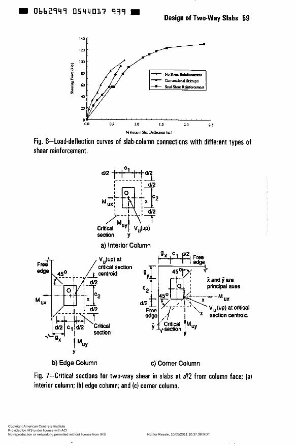
W Obb2949 0544017 939 W Design of Two-way Slabs 59
140
120
- -
- cmvsitmMlstimips
0.0 O 5 1.0 1.5 2.0 2.5
MaamimSkbDefkQion (ia.1
Fig. 6-Load-deflection curves of slab-column connections with different shear reinforcement. Fig. 6 shear
120 -
- cmvsitmMlstimips
0.0 O 5 1.0 1.5 2.0 2.5
MaamimSkbDefkQion (ia.1
i-Load-deflection curves of slab-column connections with different reinforcement.
Y
b) Edge Column
types of
c) Corner Column
Fig. 7-Critical sections for two-way shear in slabs at d/2 from column face; (a) interior column; (b) edge column; and (cl corner column.
Copyright American Concrete Institute Provided by IHS under license with ACI Licensee=AECOM User Geography and Business Line/5906698001, User=Elmorsi, Mostaf
Not for Resale, 10/05/2011 10:37:39 MDTNo reproduction or networking permitted without license from IHS
--`,``,,`,,`,,,,`,``,,,`,`,,,`,-`-`,,`,,`,`,,`---
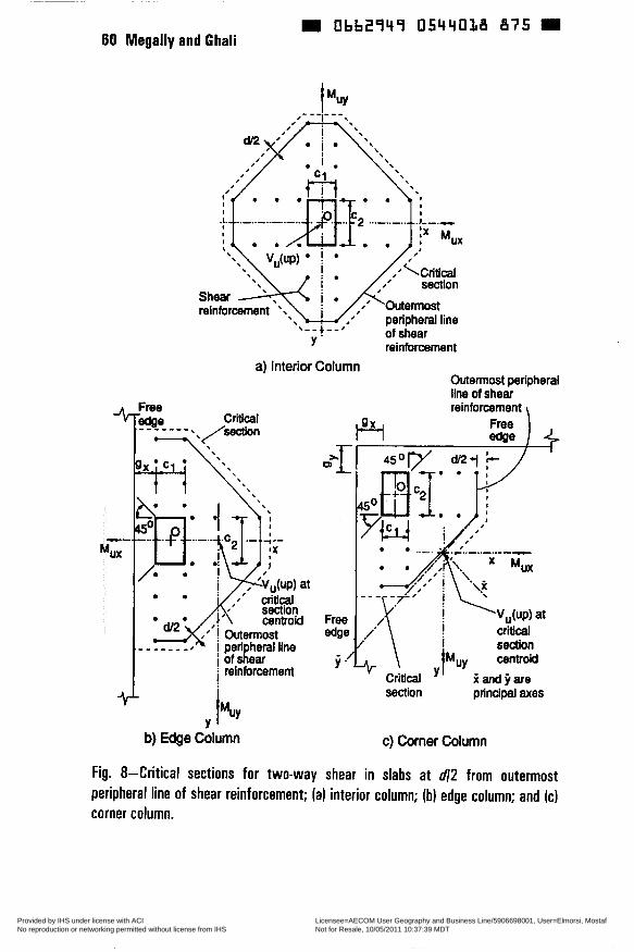
Obb2949 0544018 875 W 60 Megally and Ghali
of shear reinforcement
8 - - ! - - 8
Y
a) Interior Column Outermost peripheral ilne of shear reinforcement
l$Y 4
Y
section prind& axes
b) Edge Column c) Corner Column
Fig. 8-Critical sections for two-way shear in slabs at d/2 from outermost peripheral line of shear reinforcement; (a) interior column; (b) edge column; and IC) corner column.
Copyright American Concrete Institute Provided by IHS under license with ACI Licensee=AECOM User Geography and Business Line/5906698001, User=Elmorsi, Mostaf
Not for Resale, 10/05/2011 10:37:39 MDTNo reproduction or networking permitted without license from IHS
--`,``,,`,,`,,,,`,``,,,`,`,,,`,-`-`,,`,,`,`,,`---
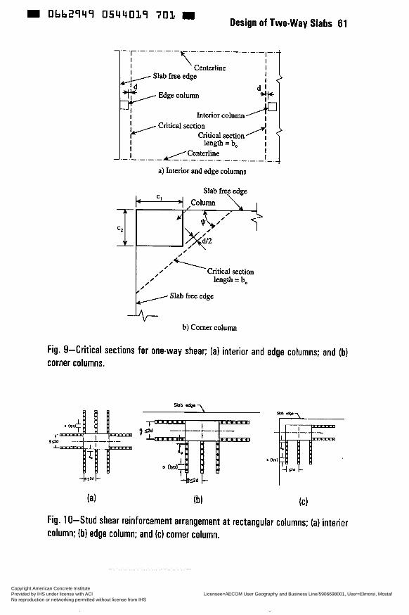
Design of Two-way Slabs 61 m Obb2949 0544019 7 0 1 m
I- I
Centerline I I ! 2
I
d l e Slab free edge I
P I Edge Interior column
Criticai section Critical section
I length = bo I I Center line I
-.-.-.-.-A/!- I !-
a) Interior and edge columns
Slab free edge
/ Critical section
/ Ø length =bo
0 I Slab free edge
b) Comer column
Fig. 9-Critical sections for one-way shear; (a) interior and edge columns; and (b) corner columns.
3-
9 %"L
(a) íbì IC)
Fig. 1 O-Stud shear reinforcement arrangement at rectangular columns; (a) interior column; (b) edge column; and (c) corner column.
Copyright American Concrete Institute Provided by IHS under license with ACI Licensee=AECOM User Geography and Business Line/5906698001, User=Elmorsi, Mostaf
Not for Resale, 10/05/2011 10:37:39 MDTNo reproduction or networking permitted without license from IHS
--`,``,,`,,`,,,,`,``,,,`,`,,,`,-`-`,,`,,`,`,,`---
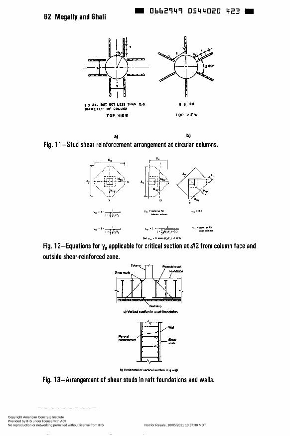
62 Megally and Ghali 0bb2949 0544020 423 m
-lT= H p DIAMETER OF COLUYN
TOP VIEW
Zd. BUT NOT L E S THAN 0.6
3 Fig. 1 1 -Stud shear reinforcement arrangement at circular columns.
orir *', . I - I I"" . I -I 1 . ; g 1.;-
mul I" - o rhn (l.lf,l c 0.1)
Fig. 12-Equations for yv applicable for critical section at ú/2 from column face and outside shear-reinforced zone.
Fig. 13-Arrangement of shear studs in raft foundations and walls.
Copyright American Concrete Institute Provided by IHS under license with ACI Licensee=AECOM User Geography and Business Line/5906698001, User=Elmorsi, Mostaf
Not for Resale, 10/05/2011 10:37:39 MDTNo reproduction or networking permitted without license from IHS
--`,``,,`,,`,,,,`,``,,,`,`,,,`,-`-`,,`,,`,`,,`---
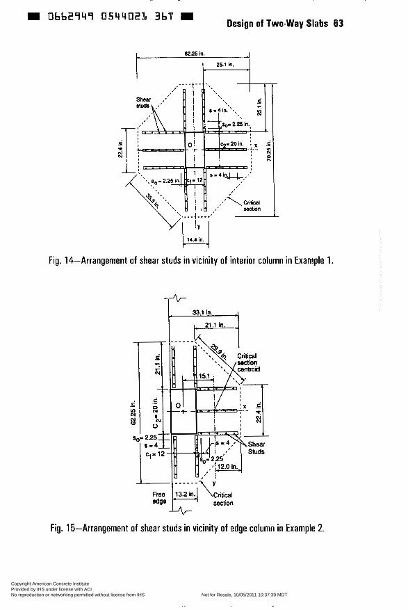
Design of Two-way Slabs Obb2949 054402L 3bT -
25.1 in.
yu 14.4 in.
Fig. 14-Arrangement of shear studs in vicinity of interior column in Example 1.
+ 33.1 in.
I 21.1 in.
Free 13.2in4 \critiai edge section
-uG Fig. 15-Arrangement of shear studs in vicinity of edge column in Example 2.
63
Copyright American Concrete Institute Provided by IHS under license with ACI Licensee=AECOM User Geography and Business Line/5906698001, User=Elmorsi, Mostaf
Not for Resale, 10/05/2011 10:37:39 MDTNo reproduction or networking permitted without license from IHS
--`,``,,`,,`,,,,`,``,,,`,`,,,`,-`-`,,`,,`,`,,`---
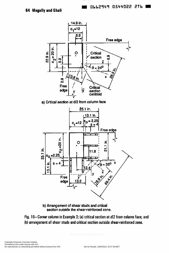
Obb2949 0544022 2Tb 64 Megally and Ghali
a) Critical section at d/2 from column face
b) Arrangement of shear studs and critical section outside the shear-reinforced zone.
Fig. 16-Corner column in Example 3; (a) critical section at d/2 from column face; and (b) arrangement of shear studs and critical section outside shear-reinforced zone.
Copyright American Concrete Institute Provided by IHS under license with ACI Licensee=AECOM User Geography and Business Line/5906698001, User=Elmorsi, Mostaf
Not for Resale, 10/05/2011 10:37:39 MDTNo reproduction or networking permitted without license from IHS
--`,``,,`,,`,,,,`,``,,,`,`,,,`,-`-`,,`,,`,`,,`---
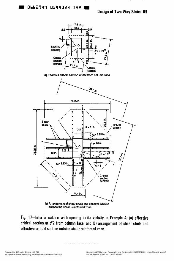
W 0662749 0544023 132 Design of Two-way Slabs 65
eedbn
a) Eiie&e criticai section at cü2 from column face
70.25 In. I
,’ centroid
b) Arrangement of shear studs and effective section outside the shear - reinforced zone.
Fig. 17-Interior column with opening in its vicinity in Example 4; (a) effective critical section at dl2 from column face; and (b) arrangement of shear studs and effective critical section outside shear reinforced zone.
Copyright American Concrete Institute Provided by IHS under license with ACI Licensee=AECOM User Geography and Business Line/5906698001, User=Elmorsi, Mostaf
Not for Resale, 10/05/2011 10:37:39 MDTNo reproduction or networking permitted without license from IHS
--`,``,,`,,`,,,,`,``,,,`,`,,,`,-`-`,,`,,`,`,,`---
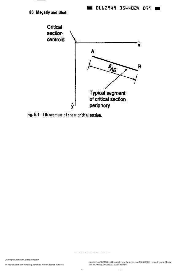
Obb29Y9 0544024 O79 m 66 Megally and Ghali
Critical
centroid
- Y
I - X
A
% Typical segment
of criticai section periphery
Fig. B.l-I th segment of shear critical section.
Copyright American Concrete Institute Provided by IHS under license with ACI Licensee=AECOM User Geography and Business Line/5906698001, User=Elmorsi, Mostaf
Not for Resale, 10/05/2011 10:37:39 MDTNo reproduction or networking permitted without license from IHS
--`,``,,`,,`,,,,`,``,,,`,`,,,`,-`-`,,`,,`,`,,`---
Obb2949 0544025 TO5 = SP 183-4
Development in Yield Line Theory for Slabs
by W. Gamble
Synopsis: The yield line theory for the determination of the ultimate load for slab structures is a well documented method of analysis. The basics of the method, which can be implemented using either equations of equilibrium or virtual work equations, are briefly reviewed, using a rectangular panel with all edges supported. A more complex single panel is then considered, followed by a brief review of multi-panel failure mechanisms. The potential importance of in-plane forces, both compression and tension, is noted. These forces, which can be thought of in arch or dome terms for compression and catenaries for tension, have led to slab failure loads much greater than can be explained on the basis of flexure alone in many tests. This phase of behavior is seldom usable for normal design of civil structures, but may be very useful and helpful in trying to understand the behavior of and design structures to resist blast loadings.
Keywords: collapse load analysis; in-plane forces; slabs; yield line analysis; yield mechanisms
67 Copyright American Concrete Institute Provided by IHS under license with ACI Licensee=AECOM User Geography and Business Line/5906698001, User=Elmorsi, Mostaf
Not for Resale, 10/05/2011 10:37:39 MDTNo reproduction or networking permitted without license from IHS
--`,``,,`,,`,,,,`,``,,,`,`,,,`,-`-`,,`,,`,`,,`---
68 Gamble Obb2949 O544026 941 D
AC1 Fellow William L. Gamble, Professor of Civil Engineering, has been a member of the faculty of the University of Illinois at Urbana-Champaign since 1963. He is engaged in teaching and research in the areas of reinforced and prestressed concrete. He is coauthor, with Robert Park, of a book on reinforced concrete slabs, and has published extensively.
Introduction
The Yield Line Method of analysis of slabs is a plastic analysis method in which a collapse mechanism is assumed - guessed- and a trial load capacity is then computed, based on the assumption. A number of different mechanisms may have to be considered, eventually leading to selection of the trial which leads to the smallest computed load capacity. The approach is first of all an analysis tool, and only secondly a design tool. It tells about the strength of a member, but not necessarily much about the behavior at service load levels, nor does it lead to information on, for example, the ratio of negative moment capacity relative to positive moment capacity which would be required for reasonable service load behavior. In spite of those limitations, it can be a useful design tool, especially for slabs with irregular shapes or odd boundary conditions. The illustrations cited here are but a few of the possible cases which have been or might be solved.
Rectangular Slab Panel
Fig. 1 shows the plan view of a rectangular slab panel which is supported at all edges and which has some edges fixed and some simply supported, but with no vertical deflection. This might be viewed as the classical case in which the yield line method has been applied to find the collapse load, wu. With either all edges fixed or all edges simply supported, it is not too hard to find tabulated solutions of the elastic moments, but when the support conditions become mixed, the available published elastic solutions diminish greatly and the yield line analysis becomes useful. This particular problem can be approached using either of two methods of analysis, with the choice depending on your preferences in mathematics.
In each case the slab is imagined to be divided into the four areas shown, separated in the interior of the panel by positive moment yield lines which represent the locations of maximum positive moment equal to the yield capacities (approximately the nominal ultimate moments) and also represent regions of concentrated flexural deformations. The panel boundaries are either negative moment yield lines, or if the edge is simply supported, lines of unrestrained rotation.
The two methods are:
Copyright American Concrete Institute Provided by IHS under license with ACI Licensee=AECOM User Geography and Business Line/5906698001, User=Elmorsi, Mostaf
Not for Resale, 10/05/2011 10:37:39 MDTNo reproduction or networking permitted without license from IHS
--`,``,,`,,`,,,,`,``,,,`,`,,,`,-`-`,,`,,`,`,,`---
(1) Virtual Work Method
One writes an equation, in terms of the three unknown dimensions, equating internal virtual work (done by the rotating areas of yielding slab) to external virtual work (done by the deflecting load). The solution is found by a simple statement:
Vary A, €3, & C to Find Minimum wu.
While the statement is simple enough, this was a formidable task in the fairly recent past. However, modern equation solving programs, including those included in current spreadsheets, can be used to find the minimum wu almost automatically once the equation has been written. Without this sort of tool, the variation of A, B, and C to find the minimum load can be a fairly blind trial-and-error process, without much guidance from Trial No. 1 to help select Trial No. 2. The equation can be solved by taking partial derivatives of the equation with respect to each variable, and then solving the resulting equations simultaneously, but this is seldom done.
(2) Equilibrium of Segments Method
In this method, equilibrium equations are written for each of the four different segments, making the assumption that there are no shear forces acting at the positive moment yield lines. The equations will ordinarily be written summing moments of the applied loads and of the resisting positive and negative moments about the supports. Again, there is a simple solution strategy statement:
Vary A, B, & C to Make wu the Same on Segments I, II, III, ¿?z IV
In this case, the solution process is not so blind. The four equations of equilibrium can be solved simultaneously, but ordinarily they will be done by trial and error, starting with some estimate (guess) about A, B, and C . However, in this case the results of Trial No. 1 will give considerable guidance about the changes needed for Trial No. 2. If the load on a particular segment is considerably larger than on the others, the segment should be enlarged. If the load is considerably smaller, the segment should be made smaller. This process converges quickly, given even a little judgement about the sizes of changes in the dimensions. A spreadsheet or other equation solver will be of great help, as it makes additional trials almost painless.
The two solutions, virtual work and equilibrium, can also be combined in some cases. Two students, working slightly before the personal computer era, were being frustrated at getting a converged solution. They found that a very quick convergence could be done by first solving the virtual work equations for wu, using any reasonable (or unreasonable) values of A, B, and C. They then back-calculated the values of A, B, and C from their equilibrium equations with their initial value of wu, and resolved for wu using the virtual work expressions with the new A, B, and C. Two iterations produced convergence in nearly every case.
Copyright American Concrete Institute Provided by IHS under license with ACI Licensee=AECOM User Geography and Business Line/5906698001, User=Elmorsi, Mostaf
Not for Resale, 10/05/2011 10:37:39 MDTNo reproduction or networking permitted without license from IHS
--`,``,,`,,`,,,,`,``,,,`,`,,,`,-`-`,,`,,`,`,,`---

Obb2949 0544028 714 W 70 Gamble
Warning Label
The caution which has to be applied to the yield line analysis is that it is an upper-bound solution. That is, the load found will be either correct or larger than the real collapse load. If one picks the wrong basic mechanism, the load fiom the converged solution could be very much too high relative to the mechanism the slab would pick if it were loaded to failure.
The mechanism show in Fig. 1 has been shown by numerous tests to be the correct basic mechanism for a slab with all edges supported, but once the panel edges are permitted to deflect, the number of possible mechanisms to be investigated may become large and not always obvious.
More Complex Single Panels
Fig. 2 shows the plan of a slab which is fixed against deflection and rotation along one edge and which has the other two comers supported by columns. There are two failure mechanisms, as shown, and there is no easy way to decide which one leads to the lower load. So both have to be analyzed. Mode 1 is simply a wide beam, while Mode 2 is fairly complex. There will be few ways of solving this problem other than yield line theory or doing a finite-element solution. The Mode 2 case will probably be most easily approached using the virtual work solution, varying two variables to obtain the minimum load. The equilibrium solution introduces some problems where the positive moment yield lines cross fiee edges at other than right angles. (See Wood (i), Wood and Jones (2) or Park and Gamble (3) for more information on this last problem.)
Fig. 3 suggests another use for the yield line theory solutions, once one has discovered, for a particular slab, that the Mode 1 load capacity is considerably higher than the Mode 2 capacity, for example. An edge beam can be added, and the analyses fairly easily altered to show its effect. As the beam is made stronger and stronger, the mechanism transitions smoothly to Mode 1. The required beam strength at this transition may be considerably less than one would expect on the basis of taking a free-body of the upper segment fkom the Mode 1 case, and assuming that the reaction acts as a uniformly distributed load on the edge beam.
Multiple-Panel Slab Cases
The previous cases are all single-panel slabs, while structures are of course usually more complex. Fig. 4 shows the end span of a “two-way” slab with beams on all column lines. If the beams are strong enough and stiff enough, the individual yield line patterns shown for the separate panels might be assumed to develop, and the capacities of each panel can be determined, independently of the neighboring panels. Such patterns have been observed in tests.
Copyright American Concrete Institute Provided by IHS under license with ACI Licensee=AECOM User Geography and Business Line/5906698001, User=Elmorsi, Mostaf
Not for Resale, 10/05/2011 10:37:39 MDTNo reproduction or networking permitted without license from IHS
--`,``,,`,,`,,,,`,``,,,`,`,,,`,-`-`,,`,,`,`,,`---
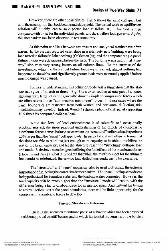
m 0662747 0544029 650 D Design of Two-way Slabs 71
However, there are other possibilities. Fig. 5 shows the same end span, but with the assumptionthat both beams and slabs yield. The virtual workor equilibrium solution will quickly lead to an expected load at failure, wu. This load is then compared with those for the individual panels, and the smallest load governs. Again, this mechanism has been observed in test structures.
At this point conflicts between test results and analytical results have often arisen. In the earliest reported case, slabs in a relatively new building were being load tested to failure in Johannesburg (Ockleston (4)), and the computed single-panel failure modes were determined before the tests. The building was a traditional “two- way” slab with very strong beams on all column lines. To the surprise of the investigator, when the theoretical failure loads were reached, almost nothing had happened to the slabs, and significantly greater loads were eventually applied before much damage was caused.
The key to understanding this behavior mode was a suggestion that the slab was acting as a flat arch or dome. Fig. 6 is a cross-section at midspan of a panel, showing fairly large deflections, and also showing in-plane compression forces which are often referred to as “compression membrane” forces. In those cases where the panel boundaries are restricted from both vertical and horizontal deflection, this mechanism may develop. Indeed, Wood (1) shows a photo of slab panel supporting 10.9 times its computed collapse load.
While this level of load enhancement is of scientific and occasionally practical interest, the more practical understanding of the effects of compressive membrane forces comes inthose cases where the “structural”col1apse load is perhaps 20% larger than the “panel” collapse loads. In such cases, it will often be found that the slabs are able to mobilize just enough extra capacity to be able to mobilize the rest of the beam capacity, and let the structure reach the “structural” collapse load and mode. Slabs have been designed utilizing the full effects of the membrane forces (Hopkins and Park (5)), but it turned out that while the reinforcement for the ultimate load could be minimized, the service load deflections could easily be excessive.
The “structural” and “panel” modes can also be used to illustrate the extreme importance of selecting the correct basic mechanism. The “panel” collapse mode can be hypothesized for beamless slabs, and the load capacities computed. However, the load capacity will be much higher than the “structurai” mode will lead to, with the difference being a factor of about three for an interior span. And without the beams to restrict deflections at the panel boundaries, there will be little opportunity for the compression membrane forces to develop.
Tension Membrane Behavior
There is also a tension membrane phase of behavior which has been observed in slabs supported on stiff beams, and in which horizontal movements of the borders
Copyright American Concrete Institute Provided by IHS under license with ACI Licensee=AECOM User Geography and Business Line/5906698001, User=Elmorsi, Mostaf
Not for Resale, 10/05/2011 10:37:39 MDTNo reproduction or networking permitted without license from IHS
--`,``,,`,,`,,,,`,``,,,`,`,,,`,-`-`,,`,,`,`,,`---
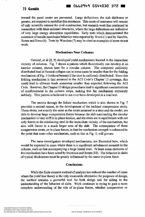
72 Gamble Obb2949 0544030 372
toward the panel center are prevented. Large deflections, the slab thickness or greater, are required to mobilize this resistance. This mode of resistance will remain of only scientific interest for civil construction, but research work has continued in connection with blast-resistant structures, where the large deflections are indicative of very large energy absorption capabilities. Early tests which demonstrated the existence of tensile membrane behavior were reported by Wood (1) and by Gamble, Sozen and Siess (6). Tests by Woodson (7) may be cited as examples of more recent work.
Mechanisms Near Columns
Gesund, et al (8, 9) developed yield mechanisms located in the immediate vicinity of columns. Fig. 7 shows a pattern which theoretically can develop at an interior column, shown here for a circular column. The computed uniformly distributed load at flexural collapse can in some cases be smaller than for the folding mechanism of Fig. 5 (without beams) if the steel is uniformly distributed. Since this folding mechanism is that assumed in the AC1 Code’s Chapter 13 coverage, this could lead to ultimate loads somewhat smaller than expected following the AC1 Code. However, the Chapter 13 design procedures lead to significant concentrations of reinforcement in the column strips, making this fan mechanism extremely unlikely. This pattern is believed to not ever have developed in a load test.
The section through the failure mechanism which is also shown in Fig. 7 provides a second reason, in the development of the inclined compression struts. These struts, not exactly the same as the struts assumed in a strut-and-tie model, are able to develop large compression forces because the slab surrounding the circular mechanism is very stiff in in-plane tension, and the struts are in equilibrium with not only forces in the reinforcing steel in the immediate vicinity of the mechanism, but also with forces in a much larger area of the slab. The consequence of these compression struts, or in-plane forces, is that the mechanism strength is enhanced to the point that some other mechanism, such as that in Fig. 5, will govern.
The same investigators developed mechanisms, not illustrated here, which would be expected in cases where there is a significant unbalanced moment in the column, such as that accompanying a large lateral load. At least some elements of this mechanism have been noted by Morrison and Sozen (10). The behavior in slabs of typical thicknesses must be greatly influenced by the same in-plane force.
Conclusions
While the finite element method of analysis has reduced the number of cases where the yield line theory is the only reasonable alternative for purposes of design, the method remains a powerful tool for both design and for aiding in the understanding of the behavior of slabs. Work continues in trying to gain a more complete understanding of the role of in-plane forces, whether compression or
Copyright American Concrete Institute Provided by IHS under license with ACI Licensee=AECOM User Geography and Business Line/5906698001, User=Elmorsi, Mostaf
Not for Resale, 10/05/2011 10:37:39 MDTNo reproduction or networking permitted without license from IHS
--`,``,,`,,`,,,,`,``,,,`,`,,,`,-`-`,,`,,`,`,,`---
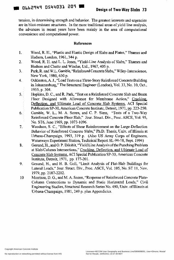
tension, in determining strength and behavior. The greatest interests and urgencies are in blast-resistant structures. In the more traditional areas of yield line analysis, the advances in recent years have been mainly in the area of computational convenience and computational power.
References
1.
2.
3.
4.
5.
6.
7.
8.
9.
10
Wood, R. H., “Plastic and Elastic Design of Slabs and Plates,” Thames and Hudson, London, 1961,344 p. Wood, R. H. and L. L. Jones, “Yield-Line Analysis of Slabs,” Thames and Hudson and Chatto and Windus, Ltd., 1967,405 p. Park, R. and W.L. Gamble, “Reinforced Concrete Slabs,” Wiley-Interscience, New York, 1980, 630 p. Ockleston, A. J., “Load Tests on a Three-Story Reinforced Concrete Building in Johannesburg,” The Structural Engineer (London), Vol. 33, No. 10, Oct., 1955, p. 304. Hopkins, D. C., and R. Park, “Test on a Reinforced Concrete Slab and Beam Floor Designed with Allowance for Membrane Action,” Crackin% Deflection, and Ultimate Load of Concrete Slab Systems, AC1 Special Publication SP-30, American Concrete Institute, Detroit, 1971, pp. 223-250. Gamble, W. L., M. A. Sozen, and C. P. Siess, “Tests of a Two-way Reinforced Concrete Floor Slab,” Jour. Struct. Div., Proc. ASCE, Vol. 95, No. ST6, June 1969, pp. 1073-1096. Woodson, S. C., “Effects of Shear Reinforcement on the Large-Deflection Behavior of Reinforced Concrete Slabs,” Ph.D. Thesis, Univ. of Illinois at Urbana-Champaign, 1993, 319 p. (Also US Army Corps of Engineers, Waterways Experiment Station, Technical Report SL-94-18, Sept. 1994) Gesund, H., and O. P. Dikshit, “Yield Line Analysis of the Punching Problem at SlabKolumn Intersections,” Cracking. Deflection, and Ultimate Load of Concrete Slab Systems, AC1 Special Publication SP-30, American Concrete Institute, Detroit, 1971, pp. 177-201. Gesund, H., and H. B. Goli, “Limit Analysis of Flat-Slab Buildings for Lateral Loads,” Jour. Struct. Div., Proc. ASCE, Vol. 105, No. ST 11, Nov.
Morrison, D. G., and M. A. Sozen, “Response of Reinforced Concrete Plate- Column Connections to Dynamic and Static Horizontal Loads,” Civil Engineering Studies, Structural Research Series No. 490, Univ. of Illinois at Urbana-Champaign, 198 1,249 p. plus Appendicies.
1979, pp. 2187-2202.
Copyright American Concrete Institute Provided by IHS under license with ACI Licensee=AECOM User Geography and Business Line/5906698001, User=Elmorsi, Mostaf
Not for Resale, 10/05/2011 10:37:39 MDTNo reproduction or networking permitted without license from IHS
--`,``,,`,,`,,,,`,``,,,`,`,,,`,-`-`,,`,,`,`,,`---
74 Gamble
~
Obb2949 0544032 b45 D
Simply Supported edge
-m Yield tine --- +m Yield Line 1-
%-y %? Fixed Edge
Fig. 1 -Yield mechanism for edge-supported rectangular slab.
Free Edge Column -
Mode 1 Mode 2
Which Has the Smaller wu?
Fig. 2-Mechanisms for slab supported on wall and columns.
to Force Mode l?
Fig. 3-Slab supported on wall, columns, and edge beam.
Copyright American Concrete Institute Provided by IHS under license with ACI Licensee=AECOM User Geography and Business Line/5906698001, User=Elmorsi, Mostaf
Not for Resale, 10/05/2011 10:37:39 MDTNo reproduction or networking permitted without license from IHS
--`,``,,`,,`,,,,`,``,,,`,`,,,`,-`-`,,`,,`,`,,`---
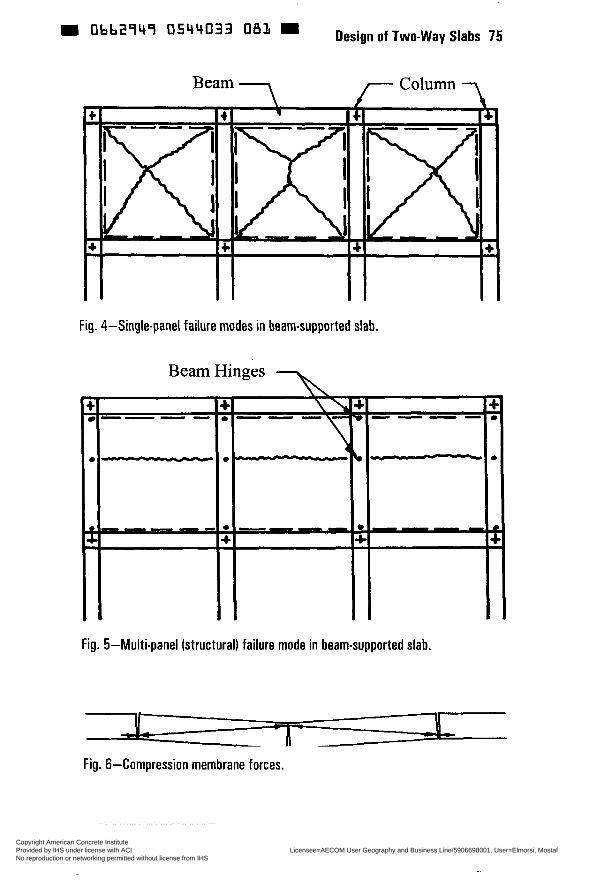
= abb29ir9 "' Design of Two-way Slabs 75
Fig. 4-Singlepanel failure mudes in beam-supported slab.
Fig. 5-Multi-panel (structural) failure mode in beam-supported slab.
Fig. 6-Compression membrane forces.
Copyright American Concrete Institute Provided by IHS under license with ACI Licensee=AECOM User Geography and Business Line/5906698001, User=Elmorsi, Mostaf
Not for Resale, 10/05/2011 10:37:39 MDTNo reproduction or networking permitted without license from IHS
--`,``,,`,,`,,,,`,``,,,`,`,,,`,-`-`,,`,,`,`,,`---
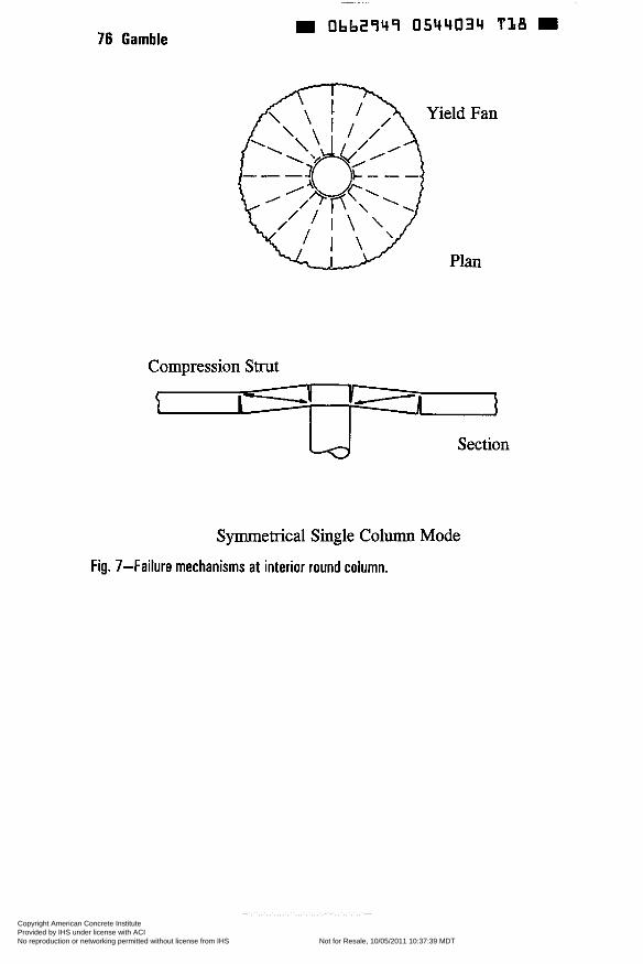
76 Gamble = Obb2949 0544034 T I 8 D
Yield Fan
Plan
Compression Strut
Section
Symmetrical Single Column Mode
Fig. 7-Failure mechanisms at interior round column.
Copyright American Concrete Institute Provided by IHS under license with ACI Licensee=AECOM User Geography and Business Line/5906698001, User=Elmorsi, Mostaf
Not for Resale, 10/05/2011 10:37:39 MDTNo reproduction or networking permitted without license from IHS
--`,``,,`,,`,,,,`,``,,,`,`,,,`,-`-`,,`,,`,`,,`---
H 0bb2949 0544035 954
SP 183-5
Using Theorums of Plasticity: History and Concept
by S. Simmonds
Synopsis: This paper reviews the requirements of the upper- and lower-bound theorems of plasticity as they apply to continuous reinforced concrete slabs. The background and assumptions leading to Johansen's yield line theory (upper-bound) and Hillerborg's strip methods (lower-bound) are presented and the advantages and disadvantages of these two methods are discussed. The segment equilibrium method proposed by Wiesinger is described and presented as an alternative procedure. It is concluded that the theory of plasticity provides a practical solution for the design of continuous reinforced concrete slabs, particularly for slab systems with irregular support geometry.
Keywords: analysis; design; equilibrium; plasticity; reinforced concrete; segment; slabs; strip method; yield line
77 Copyright American Concrete Institute Provided by IHS under license with ACI Licensee=AECOM User Geography and Business Line/5906698001, User=Elmorsi, Mostaf
Not for Resale, 10/05/2011 10:37:39 MDTNo reproduction or networking permitted without license from IHS
--`,``,,`,,`,,,,`,``,,,`,`,,,`,-`-`,,`,,`,`,,`---
m 0662949 O544036 890 m 78 Simmonds
Sidney H. Simmonds, Professor Emeritus, University of Alberta, served for many years as Secretary of the Canadian Concrete Code Committee A23.3. He has also served on AC1 Committees; 118 - Computers (Chairman 1979-83), 120 - History (Chairman 1991-95), 318F - s/c on Slabs, 334 - Shells, 340 - Handbook, 421 - Slabs, and was a founding member and first President of the Alberta AC1 Chapter.
DESIGN BY PLASTICITY
Traditionally, in North America, multi-panel reinforced concrete slabs are analyzed using elastic methods and sections proportioned using ultimate strength procedures. The theory of plasticity offers an alternative method for determining the flexural requirements in slabs that is an ultimate strength analysis.
plasticity analysis is to determine a relationship between factored load and the corresponding design moments, With plasticity analysis, this is accomplished by evaluating the load carrying capacity of the slab based solely on the flexural capacity. This requires that all other forms of failure such as shear capacity, unacceptable deflections or excessive cracking are evaluated separately and do not govern the design, a requirement in normal flexural design.
While procedures for the design of slabs based on the theory of plasticity have been used extensively in Europe for many years and were introduced into the Canadian reinforced concrete design code in 1994, they have still to be recognized explicitly in the AC1 building code. This is unfortunate since the concept of plasticity, although it can be applied to any two-way slab, has particular advantages for slabs with irregular support conditions.
Like elastic frame analysis, the purpose of
MOMENT-CURVATURE REQUIREMENTS
For the plasticity approach to be successfLII, the structural elements must be able to exhibit a large degree of plastic behavior. That is, the element must be capable of undergoing large deformations with little increase in load and maintain the load carrying capability. This is measured by the moment-curvature characteristics of the member. Typical moment-curvature response for reinforced concrete members with different levels of reinforcement are shown in Fig. 1 . It is seen that those elements that are lightly reinforced (small values of p) show the greatest ability to undergo plastic deformation. Since slabs are lightly reinforced, they may be designed using methods of analysis based on the theory of plasticity.
THE UPPER- ANTI LOWER-BOUND THEOREMS OF PLASTICITY
Whereas elastic theory gives one exact value of the load carrying capacity of the slab, the theory of plasticity gives two values, one upper-bound and one lower-bound. This is because there are two fundamentally different approaches to applying the concepts of plasticity. It is usual to define these two approaches by the two theorems of plasticity.
Copyright American Concrete Institute Provided by IHS under license with ACI Licensee=AECOM User Geography and Business Line/5906698001, User=Elmorsi, Mostaf
Not for Resale, 10/05/2011 10:37:39 MDTNo reproduction or networking permitted without license from IHS
--`,``,,`,,`,,,,`,``,,,`,`,,,`,-`-`,,`,,`,`,,`---
D Ob62949 0544037 727 = Design of Two-way Slabs 79
While several statements of the theorems of plasticity are found in the literature, the following are specific to slabs and are attributed to Hillerborg (1).
Upper-Bound Theorem: If, for a small virtual increment of deformation, the inner energy taken up be the slab on the assumption that the moment in every point where the cuwature is changed equals the yield moment and this energy is found to equal the work performed by the load wu for the same increment of deformation, then wu is an upper bound value of the carrying capacity. Loads greater than wu are certainly high enough to cause moment failure of the slab.
Lower-Bound Theorem: If there is a load w1 for which it is possible to find a moment field which fulfills all equilibrium conditions and the moment at no point is higher than the yield moment, then w1 is a lower-bound value of the load carrying capacity. The slab can certainly carry the load wl.
While the above are precise formal statements of the theorems, the essence of the concepts can be expressed more simply. An upper bound solution involves determining a load that is sufficient to cause flexural failure of the slab. As such it gives solutions that must be on the unsafe side and the object is to find the smallest such failure load for purposes of design. A lower bound solution provides a load path that satisfies equilibrium and the support conditions and where the moment at no point exceeds the yield moment. Such solutions must be on the safe side and the object is to find the solution that results in the most economic design. Obviously, if a solution can be found to satis@ both the upper and lower bounds, then it must be the exact solution in the sense that it is both safe and economical.
METHODS BASED ON THE THEOREMS OF PLASTICITY
Ail methods of plastic analysis are based on the application of either the upper- or lower-bound theorem. The two most common applications, "yield line" based on the upper-bound theorem and "strip method" based on the lower-bound theorem are the topics of two papers later in this session. Hence, this paper is limited to outlining the development of the basic concepts of these methods and a comparison of their advantages and disadvantages rather than a presentation of details of their application. Ais0 presented is a segment equilibrium method by Wiesinger that is especially attractive for column supported slabs with irregular column layouts.
It is interesting to note that the yield line and strip methods were developed essentially by single individuals, yield line by Johansen in Denmark and the strip method by Hillerborg in Sweden. This meant that their original work had to be translated into English which may be part of the reason that their use in North America is. not as extensive as in other parts of the world.
Copyright American Concrete Institute Provided by IHS under license with ACI Licensee=AECOM User Geography and Business Line/5906698001, User=Elmorsi, Mostaf
Not for Resale, 10/05/2011 10:37:39 MDTNo reproduction or networking permitted without license from IHS
--`,``,,`,,`,,,,`,``,,,`,`,,,`,-`-`,,`,,`,`,,`---
Obb2949 05ir4038 bb3 80 Simmonds
YIELD LINE THEORY
The basic premise is that, as a slab is loaded, significant portions of the reinforcement will reach its yield-point stress before the slab reaches its ultimate strength. Failure of the slab is assumed to occur when the lines along which the steel has yielded (yield lines) are sufficient to form a valid mechanism. Since elastic deformations are neglected and all deformations are assumed concentrated in the yield lines, the slab is divided by the yield lines into rigid regions which remain as plane areas. A valid failure mechanism occurs when the slab deflects causing the rigid regions to rotate about their axis of rotation defined by the support conditions while compatible rotations take place along the yield lines. Examples of yield line patterns to develop failure mechanisms are given in Fig. 2
For any pattern of yield lines that forms a mechanism there will be an infinite number of possible positions for the yield lines. The optimal or correct position is the position that results in the smallest failure load. Evaluation of the load corresponding to any assumed yield pattern is accomplished based on the principles of static equilibrium using either the virtual-work method or the equilibrium method. Finding the optimal position for a given pattern by either method does not preclude the possibility of a different pattern of yield lines giving a more critical solution so that all possible patterns resulting in a failure mechanism must be considered.
In the virtual-work method, for an assumed yield mechanism, the total (positive) work done by the ultimate load during the rigid body rotations of the slab segments is equated to the total (negative) work done by the bending and twisting moments on all of the yield lines. This method gives a single value of the failure load for the assumed position of yield lines. If the yield line pattern is simple and the work can be expressed in terms of a single geometric parameter, then the optimal position can be found by means of differential calculus. Otherwise, the optimal position is found by trial and error by successively moving the position of the yield lines until the minimum load for given moment capacities is obtained.
In the equilibrium method, again for an assumed yield mechanism, the equations of statical equilibrium are applied to each segment. The optimal position is found by trial and error and is reached when the same load is computed for each segment. The advantage of the equilibrium method is that, by examining the relative magnitudes of the failure load computed for each segment, the results from a trial give guidance as to how to move the yield lines to obtain a better position for the next trial.
The concept of analyzing a slab using the yield moment capacity was first proposed by Ingerslev (2) in 1923 for a sigle rectangular panel as shown in Fig. 3(a). He applied only yield moments along the yield lines using the equilibrium method and obtained the correct solution. However it was recognized that the same method could not be used for all slabs. Consider the slab in Fig. 3(b). At the free edge, the principal moment must cross a line that is perpendicular to the free edge. Geometry and compatibility of the rotation of the rigid segments dictate that one yield line be parallel to the simply supported sides and so intersects with the free edge at an angle other than 90 degrees. Hence the orientation of the principal
Copyright American Concrete Institute Provided by IHS under license with ACI Licensee=AECOM User Geography and Business Line/5906698001, User=Elmorsi, Mostaf
Not for Resale, 10/05/2011 10:37:39 MDTNo reproduction or networking permitted without license from IHS
--`,``,,`,,`,,,,`,``,,,`,`,,,`,-`-`,,`,,`,`,,`---
0bb2q4q 054403q 'TT Design of Two-way Slabs 81
moment and the yield moment do not coincide meaning that shear forces and /or twisting moments must also exist along the yield line.
This dilemma was not solved until 1943 when Johansen (3) presented his doctoral thesis on yield line theory to the Danmarks Tekniske Hojskole and was published in book form in Danish in 1952. His work marks the true beginning of modem yield line theory. The first paper published in English summarizing his work was by Hognestad (4) in 1953 but the full translation of his thesis ( 5 ) did not appear until 1962.
Johansen introduced the concept of nodal or knot forces. These are forces perpendicular to the plane of the slab that account for the effects of shear forces and twisting moments acting along the yield lines. Johansen had a rather simple means of computing nodal forces for orthogonally reinforced slabs. Jones and Wood (6) extended this work to cover more general cases of three intersecting yield lines with different intensities of reinforcement across each yield line.
Johansen also introduced what is referred to as the "stepped" or "square" yield criteria in which the yield moment across a yield line is determined from considering the yield line to consist of small steps at right angles to the reinforcement and simply summing the components of the yield moment of each bar. Although there has been much research to develop more sophisticated yield criteria6 his square yield criteria is still widely used.
There was also a problem of what to do with the yield line in the vicinity of a corner formed by the intersection of two non-deflecting edges. Tests show that the yield line fans into multiple yield lines near the corner. Possible treatments for this condition for a simply supported square panel having span L, with uniform load w/unit area and uniform isotropic reinforcement with yield moment capacity m are given in Fig. 4. Simply running the yield lines into the corner results in a solution of m=wL2/24. Considering the yield line pattern at the corner to be approximated by the triangular shape results in a value of m=wL2/22. If the corner fan is assumed circular, the value of m increases to of m=wL2/21.7. This ever increasing value of m was disturbing to many designers. However in 1957, Mansfield (7) proved that using hyperbolic corner fans the maximum value of m=wL2/21.4 or 12% greater than the solution neglecting comer effects. The comer effect increases as the angle becomes more acute. Johansen recognized that there were corner effects but rather than evaluate them he suggested that in practice it was satisfactory to neglect comer effects and to increase the computed required moment by 10%.
STRIP METHOD
The only practical lower-bound approach is due almost entirely to the work of Hillerborg (1,8,9,1 O, 1 1). Although Hillerborg originally referred to his method as 'equilibrium theory', it is almost universally known in English as the 'simple strip' and 'advanced strip' methods.
Hillerborg (8) satisfied the governing equations of equilibrium from plate theory assuming no contribution from torsion. If no external load is required to be carried by torsion, the slab can be considered as composed of strips, generally in
Copyright American Concrete Institute Provided by IHS under license with ACI Licensee=AECOM User Geography and Business Line/5906698001, User=Elmorsi, Mostaf
Not for Resale, 10/05/2011 10:37:39 MDTNo reproduction or networking permitted without license from IHS
--`,``,,`,,`,,,,`,``,,,`,`,,,`,-`-`,,`,,`,`,,`---
82 Simmonds m Obb2949 0544040 211
two directions at right angles, which enables the slab design moments to be calculated by simple statics involving only the equilibrium of the strips. It is for this reason that the method became known as the 'simple strip method'. Later Hillerborg (9) introduced triangular and rectangular elements for use with slabs that are supported on columns, or have reentrant comers and openings. Crawford (12) called this the 'advanced strip method'.
The simple strip method is applicable to slabs that do not have point supports (columns), supports with reentrant corners, two adjacent free edges or large point loads. Such slabs are treated with the advanced strip method
With the simple strip method, the slab surface is divided into strips that span between supports and the load is assigned to these strips to provide the best serviceability and economy based on designer judgment. The lines defining the strips and hence the regions of different load dispersion are called discontinuity lines. Within a strip, strict continuity of moment and shear is required. No attempt at continuity of moment and shear is attempted 'across discontinuity lines. For reasons of serviceability, each strip is generally analyzed using elastic theory although this is not a requirement. Since a complete moment field is obtained for each strip, reinforcement can be provided so that the yield moment is everywhere greater than the factored moment, a requirement of the lower-bound theorem.
The procedure is illustrated in Fig. 5 for a rectangular slab having two adjacent hinged and two adjacent fixed edges. Strips are selected to conform to the boundary conditions and how the load is expected to be carried to the supports. In this example, regions with a single arrow indicate that the entire load is to be carried in that direction whereas in regions with perpendicular arrows, the load is assumed to be carried equally in each direction. The term a is a fraction used to designate the strip widths and has a value less than 0.5. Smaller values of a will result in larger negative to positive moment ratios. For most slabs, good design is achieved with values of a between 0.37 and 0.40. It is seen that the relative location of the discontinuity lines can be selected so that the moment diagrams for some of the strips will be 'flat top' thereby ensuring economy in that the reinforcement provided will be utilized at maximum efficiency over much of its length.
The simple strip method also permits strips to be supported by other strips. An example would be strips along a free edge that can act as a support for other strips at right angles. Such strips have been designated as 'strong bands' by Wood and Armer (1 3).
The main feature of the advanced strip method is the introduction of the comer supported rectangular section for use with column supported slabs and slabs with reentrant comers. The dimensions of comer supported elements are selected to coincide with expected lines of zero shear. As shown in Fig. 6, equilibrium requires that the full load be carried in each direction. The sum of the average negative and positive moments along each edge is also computed from considerations of equilibrium. In each direction, this sum is proportioned between the negative and positive moment edges based on designer judgment of the overall slab geometry. Generally for column supported continuous slabs, the average negative moment is selected to be 1.5-2.0 times the average positive moment.
Copyright American Concrete Institute Provided by IHS under license with ACI Licensee=AECOM User Geography and Business Line/5906698001, User=Elmorsi, Mostaf
Not for Resale, 10/05/2011 10:37:39 MDTNo reproduction or networking permitted without license from IHS
--`,``,,`,,`,,,,`,``,,,`,`,,,`,-`-`,,`,,`,`,,`---
0662949 0544041 158 Design of Two-way Slabs 83
These moments are then distributed laterally along the element edges. While the positive moments may be distributed uniformly, it is usual to concentrate the negative moment reinforcement closer to the support resulting in 'column' and 'middle' strips. Examples of common distributions are given in Fig. 7 although other distributions can be justified. Hillerborg provides limits for the distribution of moments along the edges of the corner supported edges to ensure that the lower-bound requirements are satisfied for such elements.
COMPARISON BETWEEN YIELD LINE AND STRIP METHODS
The obvious advantage of the strip methods over the yield line method, from a designer's point of view, is that the strip methods always lead to safe designs whereas the yield line method may lead to unsafe designs unless the critical mechanism and the optimum position of the yield lines for that mechanism have been determined. When using the yield line method it is essential that the correct yield line pattern leading to the critical mechanism be considered otherwise the strength of the slab may be dangerously overestimated. Since there is no way of determining whether a particular mechanism is critical without comparing it with other mechanisms, all possible mechanisms must be investigated. This is time consuming and requires a certain degree of experience to determine less obvious patterns that may be critical, However, when the pattern for the correct failure mechanism has been established with certainty, the failure load is generally rather insensitive to the precise position of the yield lines in that pattern.
From a practical point of view, the chief advantage of the strip methods is that they are design tools. For most slab designs, the support system and the required factored loading have already been established by the overall occupancy of the structure. The flexural portion of the design is to determine the design moments from which the reinforcement is selected. This is the procedure followed with the strip methods and corresponds with the familiar elastic analysis approach. Placing reinforcement so that it can act most efficiently and locations where reinforcement 'may be terminated are natural outcomes from using the strip met hods.
To apply the yield line method, it is generally assumed that the yield moment capacity at any given point in the slab is known, that is, the slab reinforcement has already been selected. The method is then used to determine the failure load that corresponds to this reinforcement. Thus the yield line procedure, as it is usually defined, is an excellent tool for evaluating an existing slab design but is not so suitable for proportioning a slab for a given loading.
Attempts have been made to formulate the yield line method as a design tool. For example, in applying the virtual-work or equilibrium method, the load is treated as the known parameter and the corresponding required yield moment computed. However, unless it is assumed that the reinforcement intensity will everywhere be the same or will be placed in pre-established bands of known relative intensities, it is not possible to determine the Corresponding yield moments.
Copyright American Concrete Institute Provided by IHS under license with ACI Licensee=AECOM User Geography and Business Line/5906698001, User=Elmorsi, Mostaf
Not for Resale, 10/05/2011 10:37:39 MDTNo reproduction or networking permitted without license from IHS
--`,``,,`,,`,,,,`,``,,,`,`,,,`,-`-`,,`,,`,`,,`---
Obb2949 0544042 094 84 Simmonds
WIESINGER SEGMENT METHOD
In 1973, Wiesinger (14) proposed a procedure that is especially appropriate for uniformly loaded flat plates with irregularly spaced columns. The method is based on the following assumptions. Torsional moments are disregarded. Perpendicular bisectors of the lines joining columns are lines of zero shear and form the boundaries between the tributary areas of individual columns. Lines connecting the panel centers (points of intersection of the bisectors) with the comers of the column are also lines of zero shear and form the boundaries between the tributary areas of the strips. It will be seen that these line of zero shear divide the slab into a series of right angled triangles and one-way strips between columns equal to the width of the column face. Furthermore, each right angled triangle is supported by a column at one of its acute comers.
The effects of plotting the lines of zero shear for a continuous slab with rectangular panels is shown in Fig. 8. (Fig. 8 to 12 are modifications of figures in the original paper.) i n the general procedure one would work with the individual elements of the slab. However, for the case of rectangular panels, Wiesinger combines elements to form 'column' and 'middle' strips. He defines the column strip as the one-way strip between columns plus the four triangles immediately adjacent and the middle strip as the other four triangles. From the free body diagrams for these strips, also shown in Fig. 8, the total moment in a strip can be computed. To obtain the design moments, Weisinger proportions the total strip moments between the positive and negative regions in the same proportions used in the Direct Design Method. While the triangular shaped strips are used to determine the design moments, the reinforcement for each strip is distributed uniformly across bands corresponding to the traditional column and middle strip definitions. For a slab with rectangular panels the above procedure results in a slab with essentially the same reinforcement as for the Direct Design Method but without the simplicity of that method.
However, the technique has advantages when used for slabs with irregular column spacing. For such slabs, each right-angled triangle is considered separately. Moments are summed in each direction about the corner with the support. To facilitate keeping track of the calculations a notation for moments is introduced as follows. Consider triangle QRS in Fig. 8 which forms part of a column strip in the QR direction and part of a middle strip in the RS direction. The moments acting on this triangle are shown in Fig. 9 as square arrows for the perspective view. To permit representation of these moments in a plan view they are replaced by arrows with only one barb. Such arrows pointing toward the triangle represent positive moments and those pointing away indicate negative moments.
Consider the typical interior column in a flat plate with irregular column spacing designated in Fig. 10 as column A. To simpliQ presentation of the procedure it will be assumed initially that it is a point column. The intersection of the perpendicular bisectors to the five adjacent columns result in points C, E, F, G and H which define the centers of the adjacent panels and the tributary area to column A. Design moments for the four triangles in the column strip between columns A and D are shown in Fig. 1 i for a factored design load of 178 psf using
Copyright American Concrete Institute Provided by IHS under license with ACI Licensee=AECOM User Geography and Business Line/5906698001, User=Elmorsi, Mostaf
Not for Resale, 10/05/2011 10:37:39 MDTNo reproduction or networking permitted without license from IHS
--`,``,,`,,`,,,,`,``,,,`,`,,,`,-`-`,,`,,`,`,,`---
0544043 T 2 0 m Design of Two-way Slabs 85
the same proportions between positive and negative moments as specified in the Direct Design Method. Similar calculations can be made for the other four column strips framing into column A. The negative moments from all column strips framing into a column can be resolved into two perpendicular directions from which the top mat reinforcement is computed. The results of such calculations for column A are also shown in Fig. 1 1.
Wiesinger suggested that a uniform bottom mat be used over the entire slab sufficient to carry the middle strip positive moments and satis@ minimum reinforcement requirements. If required, additional bottom reinforcement is added to carry the column strip positive moment capacity. The width of the column strip is assumed to be half the distance between panel centers or, in the case for the column strip between columns A and D, half the distance between C and E as shown in Fig. 12.
The dimensions of actual columns are considered by assuming that the actual column is replaced with an equivalent column that has the same area but with a polygonal shape similar to the column tributary area. This permits defining the width of the one-way strips between columns which are then considered part of the column strip. In his paper, Wiesinger also discusses the incorporation of wails, beams and end panels.
Wiesinger claims that his method is an equilibrium method and therefore a lower-bound solution. However, he does not demonstrate that his assumptions for the locations of lines of zero shear are always valid, particularly with highly irregular column layouts and edge panels so that there may be regions where the method may not always result in a lower-bound solution. Notwithstanding this, the method has much merit and can be used by experienced designers exercising proper judgment.
CONCLUSIONS
Design procedures based on the theorems of plasticity offer attractive alternatives to methods based on elastic theory, particularly for slabs with irregular geometry due to openings and support spacing. The strip methods and the Wiesinger segment method are design procedures while the yield line method is primarily a procedure to determine the ultimate capacity of slabs with known reinforcement.
REFERENCES
1. Hillerborg, A., "Strip Method of Design," Viewpoint Publications, Cement and Concrete Association, Wexham Springs, Slough, 1975,256 pp.
2. Ingerslev, A., "The Strength of Rectangular Slabs," Journal of Institute of Structural Engineers, London, V 1 No. 1, Jan. 1923, pp. 3-19.
3. Johansen, K. W., "Brudlinieteorier", Doctoral Thesis, Danmarks Tekniske Hojskole, Copenhagen, 1943, 191 pp.
Copyright American Concrete Institute Provided by IHS under license with ACI Licensee=AECOM User Geography and Business Line/5906698001, User=Elmorsi, Mostaf
Not for Resale, 10/05/2011 10:37:39 MDTNo reproduction or networking permitted without license from IHS
--`,``,,`,,`,,,,`,``,,,`,`,,,`,-`-`,,`,,`,`,,`---
. Obb2949 0544044 î b 7 W 86 Simmonds
4. Hognestad, E., "Yield Line Theory for the Ultimate Flexural Strength of Reinforced Concrete Slabs," AC1 Journal, Proceedings, V. 49, No. 3, Mar. 1953, pp. 637-656.
5. Johansen, K. W., "Yield-Line Theory," Cement and Concrete Association, London, 1962, 18 1 pp. Translation into English of "Brudlin¡eteor¡er" Reference 3 above.
6. Jones, L. L. and Wood, R. H., "Yield-Line Analysis of Slabs," American Elsevier, New York, 1967,405 pp.
7. Mansfield, E. H., "Studies in Collapse Analysis of Rigid-Plastic Plates with a Square Yield Diagram" Proceedings, Royal Society (A), V. 241, 1957, pp. 31 1 .
8. Hillerborg, A., "Jamviktsteori for Armerade Betonplattor," Betong, V. 41, NO. 4, 1956, pp. 171-182.
9. Hillerborg, A., "Strimlemetoden for Plattorpa Pelare, Vinkelplattor m," Utgiven av Svenska Riksbyggen, Stockholm, 1959. ("Strip Method for Slabs on Columns, L-Shaped Plates, etc.," translated by F. A. Blakey, Commonwealth Scientific and Industrial Research Organization, Melbourne, 1964.)
10. Hillerborg, A., "The Advanced Strip Method - A Simple Design Tool" Magazine ofconcrete Research, V. 34, No. 121, Dec. 1982, pp. 175-181.
1 1 . Hillerborg, A, "Strip Method Design Handbook," Chapman & Hall, London, 1996,302 pp.
12. Crawford, R. E., "Limit Design of Reinforced Concrete Slabs," Ph. D. thesis, Department of Civil Engineering, University of Illinois, 1962, 163 pp.
13. Wood,.R. H. and Armer, G. S. T., "The Theory of the Strip Method for Design of Slabs," Proceedings, Institution of Civil Engineers V. 41, Oct., 1968, pp. 285-3 1 1 .
14. Wiesinger, F. P., "Design of Flat Plates with Irregular Column Layout," AC1 Journal V. 70, No. 2, Feb. 1973, pp. 1 17-123.
Copyright American Concrete Institute Provided by IHS under license with ACI Licensee=AECOM User Geography and Business Line/5906698001, User=Elmorsi, Mostaf
Not for Resale, 10/05/2011 10:37:39 MDTNo reproduction or networking permitted without license from IHS
--`,``,,`,,`,,,,`,``,,,`,`,,,`,-`-`,,`,,`,`,,`---

0bb2q4q 0544045 B T 3 Design of Two-way Slabs 87
M
p w p X- Fa ¡lu re
Small p
Unit curvature (b Fig. 1 -Moment-curvature relationship for reinforced concrete members.
simply ruppoded fixed
A-A, simply m, \ supported
/
free h e
Fig. 2-Examples of yield line patterns for valid failure mechanisms.
(a) correct soluiion (b) not correct solution
Fig. 3-Slab geometries for analyses based on yield moments only.
m=wL*/24 mwL2122 mwL2121.7
Fig. 4-Corner effects in yield line theory.
Copyright American Concrete Institute Provided by IHS under license with ACI Licensee=AECOM User Geography and Business Line/5906698001, User=Elmorsi, Mostaf
Not for Resale, 10/05/2011 10:37:39 MDTNo reproduction or networking permitted without license from IHS
--`,``,,`,,`,,,,`,``,,,`,`,,,`,-`-`,,`,,`,`,,`---
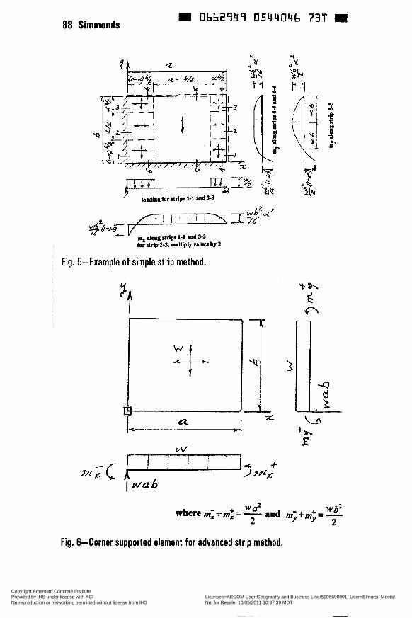
0662949 0544046 73T 88 Simmonds
# I . a
vflF-i-q-T\_Tz WL2M i?
m, h o g atdp~ 1-1 and 3-3 for strip 2-2, mulliply v i lua by 2
Fig. 5-Example of simple strip method.
_i 'Ii Fig. 6-Corner supported element for advanced strip method.
Copyright American Concrete Institute Provided by IHS under license with ACI Licensee=AECOM User Geography and Business Line/5906698001, User=Elmorsi, Mostaf
Not for Resale, 10/05/2011 10:37:39 MDTNo reproduction or networking permitted without license from IHS
--`,``,,`,,`,,,,`,``,,,`,`,,,`,-`-`,,`,,`,`,,`---
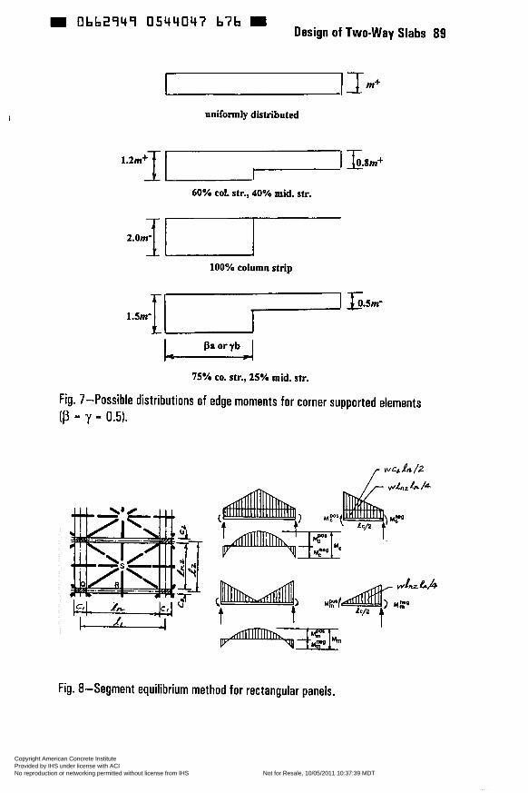
D Obb2949 0544047 b7b Design of Two-way Slabs 89
uniformly distributed
1.2m+t -1 S . û m +
60% col. str., 40% mid. str. I
100% column strip
75% CO. str., 25% mid. str.
Fig. 7-Possible distributions of edge moments for corner supported elements (ß = y = 0.5).
Fig. 8-Segment equilibrium method for rectangular panels.
Copyright American Concrete Institute Provided by IHS under license with ACI Licensee=AECOM User Geography and Business Line/5906698001, User=Elmorsi, Mostaf
Not for Resale, 10/05/2011 10:37:39 MDTNo reproduction or networking permitted without license from IHS
--`,``,,`,,`,,,,`,``,,,`,`,,,`,-`-`,,`,,`,`,,`---
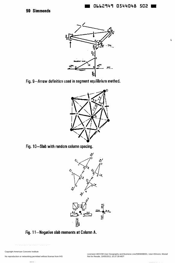
90 Simmonds
~
0662949 0544048 502 m
Fig. 9-Arrow definition used in segment equilibrium method.
Fig. 10-Slab with random column spacing.
$1
Fig. 11-Negative slab moments at Column A.
Copyright American Concrete Institute Provided by IHS under license with ACI Licensee=AECOM User Geography and Business Line/5906698001, User=Elmorsi, Mostaf
Not for Resale, 10/05/2011 10:37:39 MDTNo reproduction or networking permitted without license from IHS
--`,``,,`,,`,,,,`,``,,,`,`,,,`,-`-`,,`,,`,`,,`---
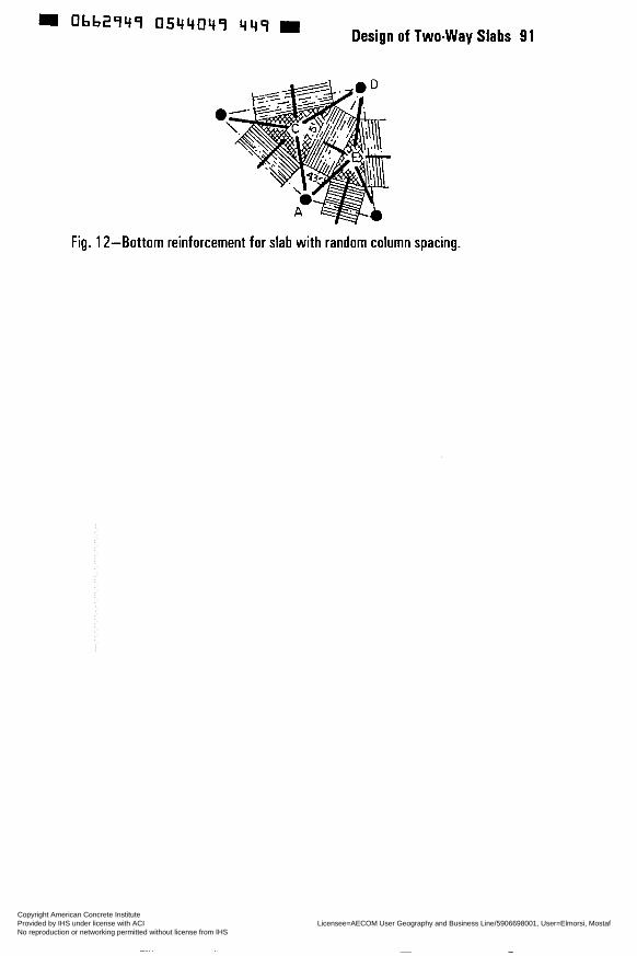
Fig. 12-Bottom reinforcement for slab with random column spacing.
Copyright American Concrete Institute Provided by IHS under license with ACI Licensee=AECOM User Geography and Business Line/5906698001, User=Elmorsi, Mostaf
Not for Resale, 10/05/2011 10:37:39 MDTNo reproduction or networking permitted without license from IHS
--`,``,,`,,`,,,,`,``,,,`,`,,,`,-`-`,,`,,`,`,,`---
Obb2949 0544050 3bO = SP 183-6
Strip Method for Flexural Desion of Two-way Slabs
by S. Alexander
Hillerborg's strip method of design (1,2) is a powerful and versatile technique for designing two-way reinforced concrete slabs and plates. The method is based on the lower bound theorem of plasticity, meaning that a design based on the strip method is always safe. The purpose of this paper is to provide an overview of the strip method, including design examples.
The strip method is usually divided into two parts. The simple strip method is used to design edge supported slabs. Many designers will recognize this as an application of the strong-band concept. The advanced strip method is used to design slabs with column supports or reentrant edge supports.
Keywords: columns; design; plates; reinforced concrete slabs
93
Copyright American Concrete Institute Provided by IHS under license with ACI Licensee=AECOM User Geography and Business Line/5906698001, User=Elmorsi, Mostaf
Not for Resale, 10/05/2011 10:37:39 MDTNo reproduction or networking permitted without license from IHS
--`,``,,`,,`,,,,`,``,,,`,`,,,`,-`-`,,`,,`,`,,`---
94 Alexander Obb2349 0544051 O T ï m
Scott Alexander is an Associate Professor of Civil and Environmental Engineering at the University of Alberta. His research interests are in the design and behavior of two-way flexural systems, the structural application of high-strength concrete, and the assessment and rehabilitation of existing structures. He is a member of AC1 committees 363-High Strength Concrete, and 42 1-Design of Reinforced Concrete Slabs.
INTRODUCTION
Hillerborg's strip method of design (1,2) is one of the most powerful and versatile techniques for designing two-way reinforced concrete slabs and plates. Like yield-line analysis, the strip method is based on the theory of plasticity. Unlike yield-line analysis, the strip method satisfies, for the most part, the lower bound theorem of plasticity. This means that, so far as flexural strength is concerned, the designer is always on the safe side using the strip method.
With the strip method of designing a two-way slab, one first assumes a pattern of load distribution and then determines average design moments that are consistent with that assumed load distribution. The load distribution scheme is made up of two types of load distribution elements: edge supported elements and comer supported elements.
The treatment of edge supported elements is usually referred to as the simple strip method. Many designers will recognize aspects of the simple strip method as a strong band approach to designing two-way slabs. While it is possible to design any slab using simple strips, certain support conditions such as columns or reentrant walls are awkward. To overcome this difficulty, Hillerborg developed a comer supported element, commonly referred to as the advanced strip method.
The purpose of this paper is to review, with design examples, the simple and advanced strip methods. The material contained here is available from a number of other sources and interested readers are urged to consult these. The most complete presentations of the strip method are in Hillerborg's books (i, 2). The first of these provides detailed theoretical development of both the simple and the advanced strip methods. The second focuses on the application of these methods in design. A journal article by Hillerborg (3) provides a concise presentation of the advanced strip method. Many textbooks on reinforced concrete design present the simple strip method and a few include material on the advanced strip method. Notable among these is Nilson (4), which devotes several chapters to slab design and one entire chapter to the strip method.
Copyright American Concrete Institute Provided by IHS under license with ACI Licensee=AECOM User Geography and Business Line/5906698001, User=Elmorsi, Mostaf
Not for Resale, 10/05/2011 10:37:39 MDTNo reproduction or networking permitted without license from IHS
--`,``,,`,,`,,,,`,``,,,`,`,,,`,-`-`,,`,,`,`,,`---
0662949 0544052 T33 Design of Two-way Slabs 95
EDGE SUPPORTED ELEMENTS: THE SIMPLE STRIP METHOD
Not counting membrane behaviour, two-way slabs carry load by means of three internal mechanisms. Relative to a rectangular coordinate system, these are bending in the x and y directions and torsion. It follows that the total load, q, at any point on the slab is made up of three components; that carried by flexure in the x and y directions (qx and qu respectively) and that carried by torsion (qJ.
Hillerborg recognized that, because of the tremendous ductility of two-way slabs, virtually any combination of qx, qv, and qxy may be used as the basis for the design of a slab as long as; (i) the slab is designed at all points to resist the moments resulting from the assumed load distribution, (ii) the shears and moments resulting from the assumed load distribution do not violate any boundary conditions (for example, the shear and moment at a free edge must be zero) and (iii) the assumed load distribution satisfies equilibrium. That is:
The simple strip method refers to one class of load distributions that is convenient for orthogonally reinforced, edge supported slabs. Choosing the x and y axes to be parailel to the reinforcement, the torsional moment relative to these axes is set to zero throughout the slab. As a result, the magnitude of qxu is also zero and the total load, q, is divided between the two bending components. Equation [ 11 is replaced with
The designer divides the total load at every point on the slab into two parts; that which spans in the x direction and that which spans in the y direction. Any strip of slab in either the x or y direction is treated as a one-way beam and designed to carry the load assigned to it.
To illustrate the simple strip method, consider a simply supported square slab of side length a = 5m subjected to a uniform load of q = 12 kN/m2, illustrated in Figures 1 through 4. One possible load distribution, shown in Figure 1, has, at every point on the slab, one-half of the load spanning in the x direction and one-half spanning in the y direction (Le. qx = qy = q/2 = 6 kN/m2). Following this load distribution, the slab would be designed across its full width, in both directions, for a mid span moment of qa2/1 6 = 18.75kN.dm.
There are two problems with this design. First, an average design moment of qa2/16 is too large for a square slab and requires too much reinforcement. Second, reinforcing for a uniform design moment across the full width of the slab places too much steel at the edge of the slab parallel to the support where
Copyright American Concrete Institute Provided by IHS under license with ACI Licensee=AECOM User Geography and Business Line/5906698001, User=Elmorsi, Mostaf
Not for Resale, 10/05/2011 10:37:39 MDTNo reproduction or networking permitted without license from IHS
--`,``,,`,,`,,,,`,``,,,`,`,,,`,-`-`,,`,,`,`,,`---

œ 0662949 OCir4053 97T œ 96 Alexander
curvatures are small, and too little in the middle of the slab where curvatures are large.
An alternate load distribution is shown in Figure 2. In this case, the slab is partitioned along the diagonals with each support carrying a triangular segment of slab. At any point on the slab, all the applied load is carried in either the x or y direction. The mid span moment for a thin strip of slab located a distance s 2 u/2 from the x-axis is qs2/2. The design moment across the width of the slab varies parabolically, from zero at the edge to a maximum value of qu2/8 in the middle.
The average value of the design moment across the width of the slab is qa2/24 = 12.5 k N d m , which is exactly the same result as one would obtain using a simple yield-line analysis with yield-lines following the load dispersion lines in Figure 2. The coincidence of upper and lower bound indicates that the solution is, in fact, exact. The solution is, however, impractical since it requires continual variations in the spacing of the reinforcement. Note that with a uniform distribution of reinforcement, the governing yield-line pattern differs from the simple load dispersion lines shown in Figure 2 in the vicinity of the simply supported corners. Accounting for this comer effect increases the average required reinforcement by approximately 1 O per cent.
Figure 3 illustrates a load distribution that leads to a banded reinforcement layout. In the central region and four corner regions, the load is distributed equally in the x and y directions. For regions along the edges of the slab all load is carried to the nearest support. This resulting design moment in both directions for the middle half of the slab is 5qa2/64 = 23.4 kN.m/m. The design moment for the outside quarters of the slab is qu2/64 = 4.7 k N d m . The average design moment over the full width of the slab is 3qu2/64 = 14.1 k N d m , which is only 13% greater than the solution shown in Figure 2.
The solutions shown in Figures 2 and 3 do not account for minimum reinforcement requirements. One of the strengths of the strip method of design is that it allows more effective use of minimum reinforcement. To satisfy deflection requirements, the example slab would have a thickness of about 150 mm (5.91in.). Minimum reinforcement for the slab would provide a factored moment resistance of about 12.3 kN-m/m. While the average design moment for the load distribution shown in Figure 3 is 14.1 k N d m , significant portions of the slab would be governed not by the calculated design moment but by minimum reinforcement requirements. With these regions reinforced for 12.3 kN*m/m in lieu of 4.7 k N d m , the average moment resistance provided is 17.85 kN-m/m.
One way to make better use of minimum reinforcement is to increase the width of the edge strips, as shown in Figure 4. The maximum width of edge strip that can be supported by minimum reinforcement is conservatively estimated as:
Copyright American Concrete Institute Provided by IHS under license with ACI Licensee=AECOM User Geography and Business Line/5906698001, User=Elmorsi, Mostaf
Not for Resale, 10/05/2011 10:37:39 MDTNo reproduction or networking permitted without license from IHS
--`,``,,`,,`,,,,`,``,,,`,`,,,`,-`-`,,`,,`,`,,`---
0bb2949 O544054 806 Design of Two-way Slabs 97
,/- = 2.02 m = 2.0 m
In other words, minimum reinforcement will support all load within the four 2m square comer regions. This leaves a lm wide central strip in each direction with a mid span design moment of 30.75 k N d m . With this scheme, the average moment resistance provided is 16.0 k N d m .
The preceding examples illustrate some important characteristics of the strip method. First, the economy of the method depends upon the choice of load distribution patterns. As a rule, carrying all load to its closest support will result in the lowest average design moments and, therefore, the most economical design. This means that load distributions are best determined using the areas of slab that are tributary to each support. As a guide, it is useful to visualize the yield-line pattern for the slab, with the yield-lines defining ideal load distribution lines. For economy, these optimal load distributions may have to be adjusted to account for minimum reinforcement. Second, unlike a yield-line analysis which provides only average reinforcement requirements, the strip method gives a clear indication of where reinforcement should be placed for greatest benefit. Bar cutoffs are easily determined since complete moment diagrams can be drawn for all strips.
Designing with the Simple Strip Method
The following examples provide a sampling of the sort of design problems using the simple strip method. Each example concerns a slab that is 150 mm (5.91in.) thick and supports a uniform factored load, including self-weight, of 12 kN/m2 (251 p.s.f.) Minimum reinforcement of grade 400 (58 k.s.i.) provides a flexural capacity of approximately 12.3 k N d m (2.77 fi,kips/ft.).
Rectangular slab with mixed supports - The rectangular slab of Figure 5 has two fixed and two simple supports, and spans 4.6 m (1 5.1 fi.) by 8 m (26.2 ft.). A simplified yield-line pattern for this slab is shown in Figure 5(a).
Figure 5(b) shows a load distribution scheme obtained by “squaring off‘ the yield line pattern of Figure 5(a). The slab is divided into eight elements of three different types: two central elements that span exclusively in the short direction, two end elements that span in the long direction, and four corner elements that carry half their load in the long direction and half in the short direction.
To produce average design moments that are close to minimum, Hillerborg suggests that the width of the central elements should be equal to the long span less one-half of the short span and the width of the end elements should be equal to one-half of the short span. With mixed support conditions, as in this
Copyright American Concrete Institute Provided by IHS under license with ACI Licensee=AECOM User Geography and Business Line/5906698001, User=Elmorsi, Mostaf
Not for Resale, 10/05/2011 10:37:39 MDTNo reproduction or networking permitted without license from IHS
--`,``,,`,,`,,,,`,``,,,`,`,,,`,-`-`,,`,,`,`,,`---
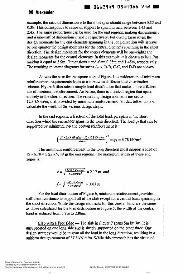
m Obb2949 0544055 742 W 98 Alexander
example, the ratio of dimension a to the short span should range between 0.35 and 0.39. This corresponds to ratios of support to span moment between 1.45 and 2.45. The same proportions can be used for the end regions, making dimensions c and d one-half of dimensions a and b respectively. Following these rules, the design moments for the end elements spanning in the long direction will always be one-quarter the design moments for the central elements spanning in the short direction. The design moments for the comer elements will be one-eighth the design moments for the central elements. In this example, a is chosen to be 1.7m making b equal to 2.9m. Dimensions c and dare 0.85m and 1.45m, respectively. The resulting moment diagrams for strips A-A, B-B, C-C, and D-D are shown.
As was the case for the square slab of Figure 1 , consideration of minimum reinforcement requirements leads to a somewhat different load distribution scheme. Figure 6 illustrates a simple load distribution that makes more efficient use of minimum reinforcement. As before, there is a central region that spans entirely in the short direction. The remaining design moments are set to 12.3 kN-m/m, that provided by minimum reinforcement. All that left to do is to calculate the width of the various design strips.
In the end regions, a fraction of the total load, qI, spans in the short direction while the remainder spans in the long direction. The load qI that can be supported by minimum top and bottom reinforcement is:
J4 x 12.3 k N d m + J îx 12.3 !d.m/m 4.6 m ) = qi = 6.78 kNlm2
The minimum reinforcement in the long direction must support a load of 12 - 6.78 = 5.22 W/m2 in the end regions. The maximum width of these end zones is:
e=,/==2.17rn and
f= ,/- = 3.07 m
For the load distribution of Figure 6, minimum reinforcement provides sufficient resistance to support all of the slab except for a central band spanning in the short direction. While the design moments for this centrai band are the same as those calculated for the load distribution in Figure 5, the width of the central band is reduced from 5.7m to 2.86111.
Slab with a Free Edge - The slab in Figure 7 spans 5m by 3m. It is unsupported on one long side and is simply supported on the other three. One design strategy would be to span all the load in the long direction, resulting in a uniform design moment of 37.5 k N d m . While this approach has the virtue of
Copyright American Concrete Institute Provided by IHS under license with ACI Licensee=AECOM User Geography and Business Line/5906698001, User=Elmorsi, Mostaf
Not for Resale, 10/05/2011 10:37:39 MDTNo reproduction or networking permitted without license from IHS
--`,``,,`,,`,,,,`,``,,,`,`,,,`,-`-`,,`,,`,`,,`---

054405b b8q Design of Two-way Slabs 99
simplicity, it fails to make any use of reinforcement that will be provided in the short direction. A more economical design involves the use of a strong band along the free edge of the slab.
Strong bands are an effective way to handle unsupported edges or large openings in slabs. A strong band is a strip of slab that acts like a beam, providing an internai support for other parts of the slab. To do this, the strong band must be designed to carry the applied load plus the internal support load.
Figure 7 shows a load distribution using a lm wide strong band along the free edge. Outside of the strong band, the slab will have minimum reinforcement in the long direction. The maximum load that can carried in the long direction by minimum reinforcement is:
= 3.94 kN/m2 12.3 kN.mim x 8 ( 5 m)’
Carrying 3.94 kN/m2 in the long direction leaves 8.06 kN/m2 to be carried in the short direction. From the loading diagram shown for section C-C, in Figure 7(b), the internal support load q, is calculated by summing moments about the simple support.
8.06 kN/m’ x2mxlm q1 = 2,5mx,m = 6.45 kN/m2
The maximum moment in the short span is 5.81 k N d m , which is less than the resistance provided by minimum reinforcement.
The strong band itself spans in the long direction and must be designed to carry a load of 12 + 6.45 = 18.45 kN/m2. The design moment for the simply supported strong band is 57.66 kN.m and the average design moment for the long span is 27.4 k N d m .
CORNER SUPPORTED ELEMENTS: THE ADVANCED STRIP METHOD
There are many instances in design where a portion of a two-way slab is tributary to a corner support. Examples of this occur at column supports or reentrant wall supports, illustrated in Figure 8. While it is possible to handle such design problems with a system of simple strips and strong bands, the resulting calculations and reinforcement patterns are often anything but simple.
To avoid these complications, Hillerborg developed the comer supported load distribution element. The design method incorporating this element was dubbed the advanced strip method, an unfortunate choice of words, for while the
Copyright American Concrete Institute Provided by IHS under license with ACI Licensee=AECOM User Geography and Business Line/5906698001, User=Elmorsi, Mostaf
Not for Resale, 10/05/2011 10:37:39 MDTNo reproduction or networking permitted without license from IHS
--`,``,,`,,`,,,,`,``,,,`,`,,,`,-`-`,,`,,`,`,,`---

1 O0 Alexander m Obb2949 0544057 5315 m
theoretical derivation of the element is quite complicated, its application in design is straightforward.
The comer supported element is a rectangular region of two-way slab with sides parallel to the flexural reinforcement. The element carries a uniform load q and is supported at one corner, with the edges of the element subject to bending moments only. All bending moments acting along an edge have the same sign or are zero. No shear forces or twisting moments act along any of the element boundaries.
Using the comer supported element is a two step procedure. First, average design moments on the element boundaries are determined to satis@ the gross equilibrium of the element. Next, these average design moments are distributed laterally according to a simple rule. This rule is required to ensure that the boundary design moments are the design moments for the entire element. In other words, if the distribution rule is satisfied, then at no point within the element will the bending moments exceed the magnitude of the boundary moments.
Figure 9 shows the distribution of design moments around the edges of one element. Consistent with Hillerborg's notation, the subscriptsfand s refer to mid span and support moments, respectively, and the subscripts x and y refer to the directions of the span. Rotational equilibrium of the element about its x and y axes imposes the following conditions on the average support and span moments in each direction.
In [3] and [4] the subscript m indicates a mean bending moment intensity across the width of the entire element. The moments qa2/2 and qbV2 are called cantilever moments. Note that a corner supported element must carry the entire distributed load w in both the x and y directions.
Consistent with standard practice, the boundary moments in each direction are subdivided into two bands, as shown in Figure 9. In the standard case, the width of each band is one-half the width of the element. The bands are subscripted 1 and 2 and are conceptually the same as the column and middle strips defined by AC1 3 18-95 (5).
The rule for the lateral distribution of design moment is expressed in terms of the "middle" strip moments. Typically, where the width of the column support strip (subscripts 1 and s) is one-half the width of the element, the middle strip moments should satisfy the following.
Copyright American Concrete Institute Provided by IHS under license with ACI Licensee=AECOM User Geography and Business Line/5906698001, User=Elmorsi, Mostaf
Not for Resale, 10/05/2011 10:37:39 MDTNo reproduction or networking permitted without license from IHS
--`,``,,`,,`,,,,`,``,,,`,`,,,`,-`-`,,`,,`,`,,`---
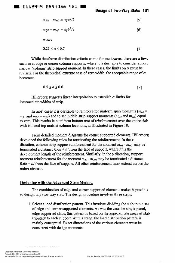
m Ob62949 054Lt058 451 II Design of Two-way Slabs 101
mf.2 - msx2 = aqu2/2 PI
where
0.25 I a 50.7 [71
While the above distribution criteria works for most cases, there are a few, such as at edge or corner column supports, where it is desirable to consider a more narrow "column" strip support moment. In these cases, the limits on a must be revised. For the theoretical extreme case of zero width, the acceptable range of a becomes:
0.5 5 a 5 0.6 181
Hillerborg suggests linear interpolation to establish a limits for intermediate widths of strip.
In most cases it is desirable to reinforce for uniform span moments (mIxl =
m,,, and mfil = mfiz) and to set middle strip support moments (ms2 and m,,) equal to zero. This results in a uniform bottom mat of reinforcement over the entire slab with isolated top mats at column locations, as illustrated in Figure 10.
From detailed moment diagrams for corner supported elements, Hillerborg developed the following rules for terminating the reinforcement. In the x direction, column strip support reinforcement for the moment m,] - ms2 may be terminated a distance 0 . 6 ~ + Id from the face of support, where Id is the development length of the reinforcement. Similarly, in the y direction, support moment reinforcement for the moment mvyl - m vz may be terminated a distance 0.6b + Id from the face of support. All other reinforcement must extend across the entire element.
Designing with the Advanced Strip Method
to design any two-way slab. The design procedure involves three steps: The combination of edge and corner supported elements makes it possible
1. Select a load distribution pattern. This involves dividing the slab into a set of edge and comer supported elements. As was the case for single panel, edge supported slabs, this pattern is based on the approximate areas of slab tributaxy to each support. At this stage, the load distribution pattern is mainly conceptual. Exact dimensions of the various elements must be consistent with design moments.
Copyright American Concrete Institute Provided by IHS under license with ACI Licensee=AECOM User Geography and Business Line/5906698001, User=Elmorsi, Mostaf
Not for Resale, 10/05/2011 10:37:39 MDTNo reproduction or networking permitted without license from IHS
--`,``,,`,,`,,,,`,``,,,`,`,,,`,-`-`,,`,,`,`,,`---
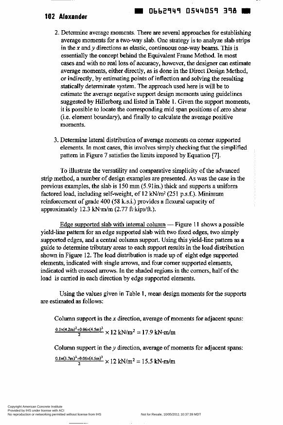
102 Alexander W 0662949 0544059 398
2. Determine average moments. There are several approaches for establishing average moments for a two-way slab. One strategy is to analyze slab strips in the x and y directions as elastic, continuous one-way beams. This is essentially the concept behind the Equivalent Frame Method. In most cases and with no real loss of accuracy, however, the designer can estimate average moments, either directly, as is done in the Direct Design Method, or indirectly, by estimating points of inflection and solving the resulting statically determinate system. The approach used here is will be to estimate the average negative support design moments using guidelines suggested by Hillerborg and listed in Table 1. Given the support moments, it is possible to locate the corresponding mid span positions of zero shear (i.e. element boundary), and finally to calculate the average positive moments.
3. Determine lateral distribution of average moments on corner supported elements. In most cases, this involves simply checking that the simplified pattern in Figure 7 satisfies the limits imposed by Equation [7].
To illustrate the versatility and comparative simplicity of the advanced strip method, a number of design examples are presented. As was the case in the previous examples, the slab is 150 mm (5.91in.) thick and supports a uniform factored load, including self-weight, of 12 kN/m2 (251 p.s.f.). Minimum reinforcement of grade 400 (58 k.s.i.) provides a flexural capacity of approximately 12.3 kN.m/m (2.77 ft-kips/ft.).
Edge supported slab with internal column - Figure 1 1 shows a possible yield-line pattern for an edge supported slab with two fixed edges, two simply supported edges, and a central column support. Using this yield-line pattern as a guide to determine tributary areas to each support results in the load distribution shown in Figure 12. The load distribution is made up of eight edge supported elements, indicated with single arrows, and four corner supported elements, indicated with crossed arrows. In the shaded regions in the comers, half of the load is carried in each direction by edge supported elements.
Using the values given in Table 1, mean design moments for the supports are estimated as follows:
Column support in the x direction, average of moments for adjacent spans:
Column support in the y direction, average of moments for adjacent spans:
x 12 kN/m2 = 15.5 k N d m O. 1~(3.7m)*+0.06x(4.5rn)* 2
Copyright American Concrete Institute Provided by IHS under license with ACI Licensee=AECOM User Geography and Business Line/5906698001, User=Elmorsi, Mostaf
Not for Resale, 10/05/2011 10:37:39 MDTNo reproduction or networking permitted without license from IHS
--`,``,,`,,`,,,,`,``,,,`,`,,,`,-`-`,,`,,`,`,,`---

W Obb2949 05440b0 OUT W Design of Two-way Slabs 103
Edge support in the x or y direction:
12 kN/m2x(4.5m)2 = 20.3 12
The element boundaries at mid span are positions of zero shear. Their position is determined using the support moments, span length, and loading. Mid span design moments are then calculated by considering the equilibrium of individual elements. For example, for a strip spanning in the x direction between the column and the fixed edge, the average distance from the edge to the location of zero shear is:
20.3 kN.m/m-17.9 k N d m + y = 2.29 4.5 m x 1 2 kN/mZ
Considering equilibrium of the edge supported element, the maximum
positive moment is:
- 20.3 k N d m = 11.2 k N d m 12 kN/m2 x ( 2 . 2 9 d 2 2
The moment diagrams resulting from these calculations are shown in Figure 12(a). Applying the lateral distribution pattern illustrated in Figure 7 results in the distribution of design moments shown in Figures 12(b) and (c). Support design moments are double the average support moment and are spread over half the element width. All a values are within allowable limits as follows:
18.2 k N d m 18.2 kNm/m+17.9 k N d n = 0.504
11.2 k N d m 11.2 kN.dm+l7 .9 k N d m =
12.6 k N . d m 12.6 kN.m/m+lS.S k N d m =
13.5 k N d m 13.5 kN.m/m+15.5 k N d m =
Because load in the shaded corner regions is divided equally between spanning in the x and y directions, the design moments are conservatively estimated at half the value of the adjacent simple strips. Further refinement is not worthwhile since these moments are all well below that provided by minimum reinforcement.
Slab with edpe column - Figure 13 shows a two-way slab similar to the preceding example except that one of the simple edge supports is replaced by a column. The average moments for spanning in the y direction are unchanged from the previous example.
Copyright American Concrete Institute Provided by IHS under license with ACI Licensee=AECOM User Geography and Business Line/5906698001, User=Elmorsi, Mostaf
Not for Resale, 10/05/2011 10:37:39 MDTNo reproduction or networking permitted without license from IHS
--`,``,,`,,`,,,,`,``,,,`,`,,,`,-`-`,,`,,`,`,,`---

Obb2947 0544QbL T4b 104 Alexander
Except at the edge column support, bending moments for spanning in the x direction are calculated using the coefficients of Table 1. The appropriate value of design moment at the edge column is somewhat debatable. The Direct Design Method would suggest 26% of the simple span moment. In the opinion of the author, this value is a littie high, particularly if the reinforcement is placed well outside the column. A more modest value of 20% of the simple span moment is chosen for this example. This gives an average support moment and total support moment, respectively, of:
o.2 (4.2 m)'x12 kN/mz 8 = 5.3 k N d m and
(2.2 m + 0.3 m + 2.16 m) x 5.3 kN.mírn= 24.7 kN.m
All other mean design moments are as shown in Figure 13(a). The support moment at the edge column will be carried by steel within the column width plus three times the slab thickness, for a total width of 750 mm. This produces a design moment intensity at the edge column of 32.9 kN.m/m.
The lateral distribution of design moments is shown in Fig 13(b) and (c). Of particular interest is the distribution of bottom steel perpendicular to the free edge. Because the support moment at the edge column is placed in a band that is narrower than half the design strip, the limits on ct must be adjusted for the two corner supported elements labeled A. The mid span moment must also satisfy the limits on a for the two elements labeled B but in this example, the constraint from the A elements is more severe. This leads to the following constraint on the "middle strip" positive moment, mjxz,
For element A:
0.42 5 ,z5,3 I 0.63
8.82 k N d m 5 r n ~ 2 5 13.23 kNm/m
The value of mfi2 will be set to 12.3 k N d m , corresponding to minimum reinforcement. To satisfy the mean positive moment requirements for the elements, the "column strip" reinforcement must be designed to resist 19.1 k N d m .
Slab with cantilever - The slab in Figure 14 illustrates the versatility of the corner supported element. The two comer supported elements adjacent to the fiee edge, labeled A, are constrained to have a span moment of zero. As a result, the distribution of the top reinforcement perpendicular to the free edge must satis@ the limits on a for these edge elements. However, this distribution of support moment must be compatible with the requirements of the interior
Copyright American Concrete Institute Provided by IHS under license with ACI Licensee=AECOM User Geography and Business Line/5906698001, User=Elmorsi, Mostaf
Not for Resale, 10/05/2011 10:37:39 MDTNo reproduction or networking permitted without license from IHS
--`,``,,`,,`,,,,`,``,,,`,`,,,`,-`-`,,`,,`,`,,`---

= 0bb2949 05440b2 982 = Design of Two-way Slabs 105
elements, labeled B. This leads to the following constraints on the "middle strip" support moment, mm2 at the outermost column.
For element A:
0.25 I 2 I 0.70
3.38 k N d m I mj.2 29.45 k N d m
For element B:
m,2+12.4 0.25 < - < 0.70
-5.93 IrN-dm I mfx2 I 5.73 k N d m
The value of mm2 will be set to 4.0 k N d m , leading to a design moment for the "column strip" reinforcement of 23.0 k N d m .
It should be noted that equilibrium for the shaded comer regions of the three preceding examples is not strictly satisfied. While it is possible to develop load distributions that rigorously satisfy the equilibrium of these sections, the difference in final design moments will be negligible. Because the design moments are well below that provided by minimum reinforcement, a more refined analysis will not change the final reinforcement layout.
Simulv suuuorted L-shaped slab - Figure 15 shows an L-shaped slab simply supported on all edges. The load distribution in Figure 15(a) features a single corner supported element at the reentrant comer of the edge support. The discussion here will concern mainly the design moments for this element as the rest of the slab is easily handled by simple strips.
The corner supported element is assumed to extend slightly more than half way across the slab, say 2.4 m. This leads to the distribution of average moments at section A-A shown in the figure.
The average support moment of 10.6 k N d m will be carried by top reinforcement concentrated over one quarter of the element width or 1.1 m. The limits on 01 are revised to:
0.375 5 a 2 0.65
The final distribution of design moments is shown in Figure 15(b) for reinforcement in the y direction only. By symmetry, the design moments for steel in the x direction are the same.
Copyright American Concrete Institute Provided by IHS under license with ACI Licensee=AECOM User Geography and Business Line/5906698001, User=Elmorsi, Mostaf
Not for Resale, 10/05/2011 10:37:39 MDTNo reproduction or networking permitted without license from IHS
--`,``,,`,,`,,,,`,``,,,`,`,,,`,-`-`,,`,,`,`,,`---
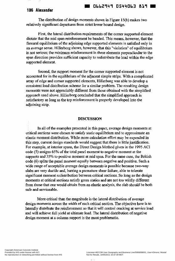
106 Alexander
~ ~
m Ob62949 05440b3 819 m
The distribution of design moments shown in Figure 1501) makes two relatively significant departures from strict lower bound design.
First, the lateral distribution requirements of the corner supported element dictate that the mid span reinforcement be banded. This means, however, that the flexural equilibrium of the adjoining edge supported elements is satisfied only in an average sense. Hillerborg shows, however, that this "violation" of equilibrium is not serious; the minimum reinforcement in these elements perpendicular to the span direction provides sufñcient capacity to redistribute the load within the edge supported element.
Second, the support moment for the corner supported element is not accounted for in the equilibrium of the adjacent simple strips. With a complicated array of edge and corner supported elements, Hillerborg was able to develop a consistent load distribution scheme for a similar problem. The resulting design moments were not appreciably different from those obtained with the simplified approach used above. Hillerborg concluded that the simplified approach is satisfactory as long as the top reinforcement is properly developed into the adjoining strip.
DISCUSSION
In all of the examples presented in this paper, average design moments at critical sections were chosen to satis@ static equilibrium and to approximate an elastic moment distribution. While more calculation effort may be expended in this step, current design standards would suggest that there is little justification. For example, at interior spans, the Direct Design Method given in the 1995 AC1 code ( 5 ) assigns 65% of the total panel moment to negative moment at the supports and 35% to positive moment at mid span. For the same case, the British code (6) splits the panel moment equally between negative and positive. Such a wide range of acceptable average design moments is possible because two-way slabs are very ductile and, barring a premature shear failure, able to tolerate significant moment redistribution between critical sections. So long as the design moments at critical sections satis@ gross statics and are not too wildly different from those that one would obtain from an elastic analysis, the slab should be both safe and serviceable.
More critical than the magnitude is the lateral distribution of average design moments across the width of each critical section. The objective here is to laterally distribute the reinforcement so that it will control cracking at service load and will achieve full yield at ultimate load. The lateral distribution of negative design moment at a column support is the most problematic.
Copyright American Concrete Institute Provided by IHS under license with ACI Licensee=AECOM User Geography and Business Line/5906698001, User=Elmorsi, Mostaf
Not for Resale, 10/05/2011 10:37:39 MDTNo reproduction or networking permitted without license from IHS
--`,``,,`,,`,,,,`,``,,,`,`,,,`,-`-`,,`,,`,`,,`---
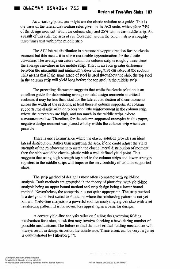
9 Obbtî4î 05440b4 755 Design of Two-way Slabs 107
As a starting point, one might use the elastic solution as a guide. This is the basis of the lateral distribution rules given in the AC1 code, which place 75% of the design moment within the column strip and 25% within the middle strip. As a result of this rule, the area of reinforcement within the column strip is roughly three times that within the middle strip.
The AC1 lateral distribution is a reasonable approximation for the elastic moment but this means it is also a reasonable approximation for the elastic curvature. The average curvature within the column strip is roughly three times the average curvature in the middle strip. There is an even greater difference between the maximum and minimum values of negative curvature at the section. This means that if the same grade of steel is used throughout the slab, the top steel in the column strip will yield long before the top steel in the middle strip.
The preceding discussion suggests that while the elastic solution is an excellent guide for determining average or total design moments at critical sections, it may be less than ideal for the lateral distribution of these moments across the width of the sections, at least those at column supports. At column supports, the elastic solution places too little reinforcement in the column strip, where the curvatures are high, and too much in the middle strips, where curvatures are low. Therefore, for the column supported examples in this paper, negative design moment was placed wholly within the column strip whenever possible.
There is one circumstance where the elastic solution provides an ideal lateral distribution. Rather than adjusting the area, if one could adjust the yield strength of the reinforcement to match the elastic lateral distribution of moment, then the slab would be elastic- plastic with a well defined yield point. This suggests that using high-strength top steel in the column strips and lower strength top steel in the middle strips will improve the serviceability of column-supported slabs.
The strip method of design is most often compared with yield-line analysis. Both methods are grounded in the theory of plasticity, with yield-line analysis being an upper bound method and strip design being a lower bound method. Nevertheless, the comparison is not quite appropriate. The strip method is a design tool, best suited to situations where the reinforcing pattern is not yet known. Yield-line analysis is a powerful tool for analyzing a given slab with a set reinforcing pattern. It is, however, less appealing as a basis for design.
A correct yield-line analysis relies on finding the governing folding mechanism for a slab, a task that may involve checking a bewildering number of possible mechanisms. The failure to find the most critical folding mechanism will always result in design errors on the unsafe side. These errors can be very large, as is demonstrated by Hillerborg (7).
Copyright American Concrete Institute Provided by IHS under license with ACI Licensee=AECOM User Geography and Business Line/5906698001, User=Elmorsi, Mostaf
Not for Resale, 10/05/2011 10:37:39 MDTNo reproduction or networking permitted without license from IHS
--`,``,,`,,`,,,,`,``,,,`,`,,,`,-`-`,,`,,`,`,,`---
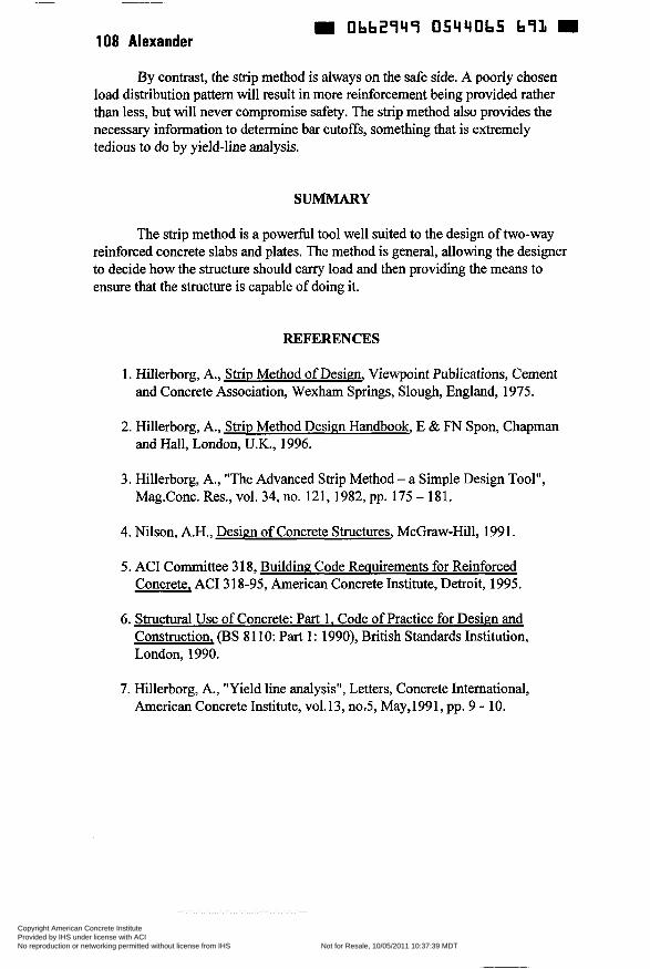
m Obb29q9 05440b5 b91i m 108 Alexander
By contrast, the sûip method is always on the safe side. A poorly chosen load distribution pattern will result in more reinforcement being provided rather than less, but will never compromise safety. The strip method also provides the necessary information to determine bar cutoffs, something that is extremely tedious to do by yield-line analysis.
SUMMARY
The strip method is a powerful tool well suited to the design of two-way reinforced concrete slabs and plates. The method is general, allowing the designer to decide how the structure should carry load and then providing the means to ensure that the structure is capable of doing it.
REFERENCES
1. Hillerborg, A., Strip Method of Desim, Viewpoint Publications, Cement and Concrete Association, Wexham Springs, Slough, England, 1975.
2. Hillerborg, A., Strip Method Design Handbook, E & FN Spon, Chapman and Hall, London, U.K., 1996.
3. Hillerborg, A., "The Advanced Strip Method - a Simple Design Tool", Mag.Conc. Res., vol. 34, no. 121, 1982, pp. 175 - 181.
4. Nilson, A.H., Design of Concrete Structures, McGraw-Hill, 1991.
5. AC1 Committee 3 18, Building Code Requirements for Reinforced Concrete, AC1 3 18-95, American Concrete Institute, Detroit, 1995.
6. Structural Use of Concrete: Part 1. Code of Practice for Design and Construction, (BS 8 1 10: Part 1 : 1990), British Standards Institution, London, 1990.
7. Hillerborg, A., "Yield line analysis", Letters, Concrete International, American Concrete Institute, vo1.13, noS, May,1991, pp. 9 - 10.
Copyright American Concrete Institute Provided by IHS under license with ACI Licensee=AECOM User Geography and Business Line/5906698001, User=Elmorsi, Mostaf
Not for Resale, 10/05/2011 10:37:39 MDTNo reproduction or networking permitted without license from IHS
--`,``,,`,,`,,,,`,``,,,`,`,,,`,-`-`,,`,,`,`,,`---
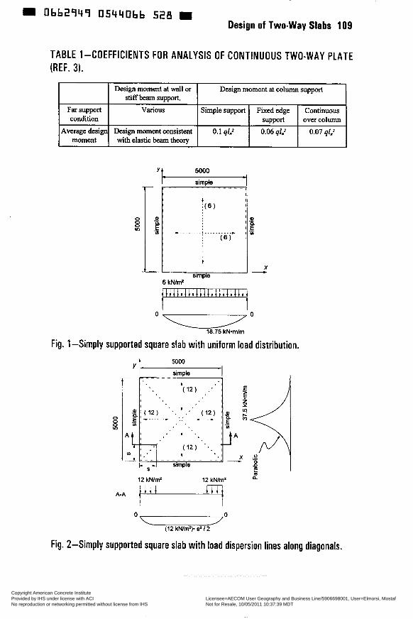
0bb2949 05440bb 5iIõ Design of Two-way Slabs 1 O9
TABLE 1-COEFFICIENTS FOR ANALYSIS OF CONTINUOUS TWO-WAY PLATE (REF. 3).
Y 5000
sirnde
x ln -1 O n 0 10.75 kN*m/rn
Fig. 1 -Simply supported square slab with uniform load distribution.
a 12 kNlrn' 12 kNimz
A+ 1-y (12 kNlm'). s'/ 2
Fig. 2-Simply supported square slab with load dispersion lines along diagonals.
Copyright American Concrete Institute Provided by IHS under license with ACI Licensee=AECOM User Geography and Business Line/5906698001, User=Elmorsi, Mostaf
Not for Resale, 10/05/2011 10:37:39 MDTNo reproduction or networking permitted without license from IHS
--`,``,,`,,`,,,,`,``,,,`,`,,,`,-`-`,,`,,`,`,,`---
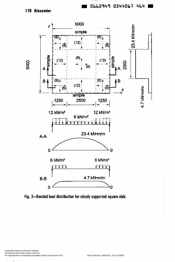
~
Ob62949 05440b7 4b4 m 1 1 O Alexander
O O O v)
I simple I
6 kN/mZ 6 kN/m2
I 4.7 kN*m/m I B-B
O 1 0
Fig. 3-Banded load distribution for simply supported square slab.
Copyright American Concrete Institute Provided by IHS under license with ACI Licensee=AECOM User Geography and Business Line/5906698001, User=Elmorsi, Mostaf
Not for Resale, 10/05/2011 10:37:39 MDTNo reproduction or networking permitted without license from IHS
--`,``,,`,,`,,,,`,``,,,`,`,,,`,-`-`,,`,,`,`,,`---
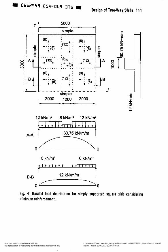
12 kN/m2 6 kN/m2 12 kN/m2
30.75 kNvn/m 1
6 kN/m2 6 kN/m2
t t i t t t t
I 12 kN*m/m I B-B
O
O o 7
Fig. 4-Banded load distribution for simply supported square slab considering minimum reinforcement.
Copyright American Concrete Institute Provided by IHS under license with ACI Licensee=AECOM User Geography and Business Line/5906698001, User=Elmorsi, Mostaf
Not for Resale, 10/05/2011 10:37:39 MDTNo reproduction or networking permitted without license from IHS
--`,``,,`,,`,,,,`,``,,,`,`,,,`,-`-`,,`,,`,`,,`---
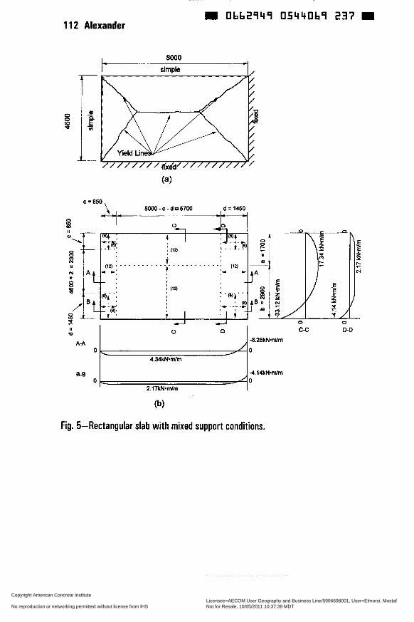
0bb2949 05440b9 237 1 12 Alexander
8000 . -I
O
9
simple
8000 - C - d 67W d = 1450 c=850\ k-cl- .--
-8.28kN-mlm
O 4.34kN.mlm
6-6 4 1 4 k N m h O O O 4 2.17kN-mlm (b)
.o
T / O
D-D
Fig. 5-Rectangular slab with mixed support conditions.
Copyright American Concrete Institute Provided by IHS under license with ACI Licensee=AECOM User Geography and Business Line/5906698001, User=Elmorsi, Mostaf
Not for Resale, 10/05/2011 10:37:39 MDTNo reproduction or networking permitted without license from IHS
--`,``,,`,,`,,,,`,``,,,`,`,,,`,-`-`,,`,,`,`,,`---
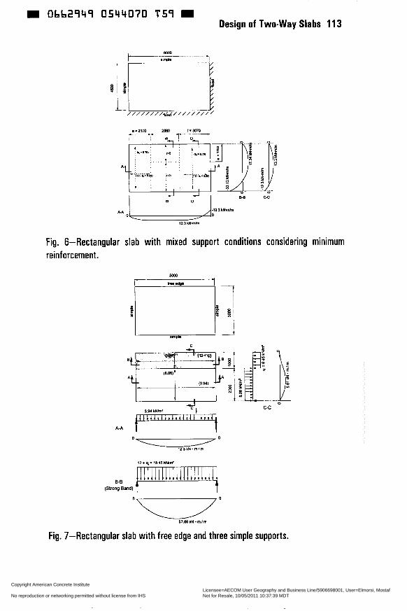
Obb2949 0544070 T59 Design of Two-way Slabs 11 3
Fig. 6-Rectangular slab with mixed support conditions considering minimum reinforcement.
A A
12+q,=1815kWnV
8-8 (Strang Band)
c-c
Fig. 7-Rectangular slab with free edge and three simple supports.
Copyright American Concrete Institute Provided by IHS under license with ACI Licensee=AECOM User Geography and Business Line/5906698001, User=Elmorsi, Mostaf
Not for Resale, 10/05/2011 10:37:39 MDTNo reproduction or networking permitted without license from IHS
--`,``,,`,,`,,,,`,``,,,`,`,,,`,-`-`,,`,,`,`,,`---
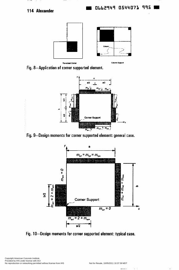
-
114 Alexander 0662949 05440’71 995 m
ReFnmltcoma
Fig. 8-Application of corner supported element.
Fig. 9-Design moments for corner supported element: general case.
Y a
If
O II
Comer Support
t-z---i Fig. 1 O-Design moments for corner supported element: typical case.
t X
Copyright American Concrete Institute Provided by IHS under license with ACI Licensee=AECOM User Geography and Business Line/5906698001, User=Elmorsi, Mostaf
Not for Resale, 10/05/2011 10:37:39 MDTNo reproduction or networking permitted without license from IHS
--`,``,,`,,`,,,,`,``,,,`,`,,,`,-`-`,,`,,`,`,,`---
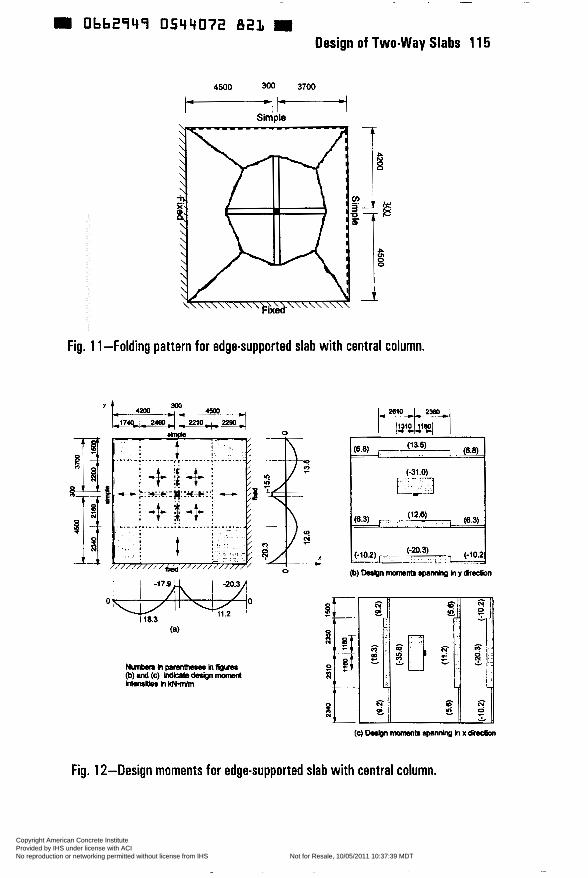
~
Obb291fq 0544072 82L Design of Two-way Slabs 1 15
4500 300 3700
i-P----l SimDle
Fig. 1 1-Folding pattern for edge-supported slab with central column.
(c) üesign m t r spandng h x dirmkn
Fig. 1 2-Design moments for edge-supported slab with central column.
Copyright American Concrete Institute Provided by IHS under license with ACI Licensee=AECOM User Geography and Business Line/5906698001, User=Elmorsi, Mostaf
Not for Resale, 10/05/2011 10:37:39 MDTNo reproduction or networking permitted without license from IHS
--`,``,,`,,`,,,,`,``,,,`,`,,,`,-`-`,,`,,`,`,,`---
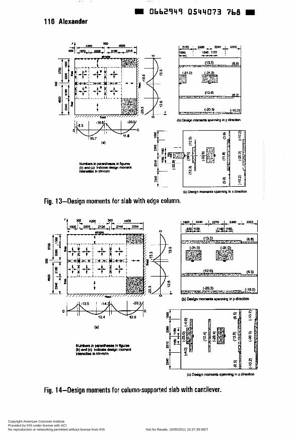
1 16 Alexander
~
Obb294ï 0544073 7b8 W
Fig.
Nvrklh-hfWm (b) uid (c) Mlats dedm mansnl iriaslissnm
(c) W i n mwnents spnnirg h x direcöon
, 13-Design moments for slab with edge column.
(c) W I n -b rpnnig m x dieelion
Fig. 14-Design moments for column-supported slab with cantilever.
Copyright American Concrete Institute Provided by IHS under license with ACI Licensee=AECOM User Geography and Business Line/5906698001, User=Elmorsi, Mostaf
Not for Resale, 10/05/2011 10:37:39 MDTNo reproduction or networking permitted without license from IHS
--`,``,,`,,`,,,,`,``,,,`,`,,,`,-`-`,,`,,`,`,,`---
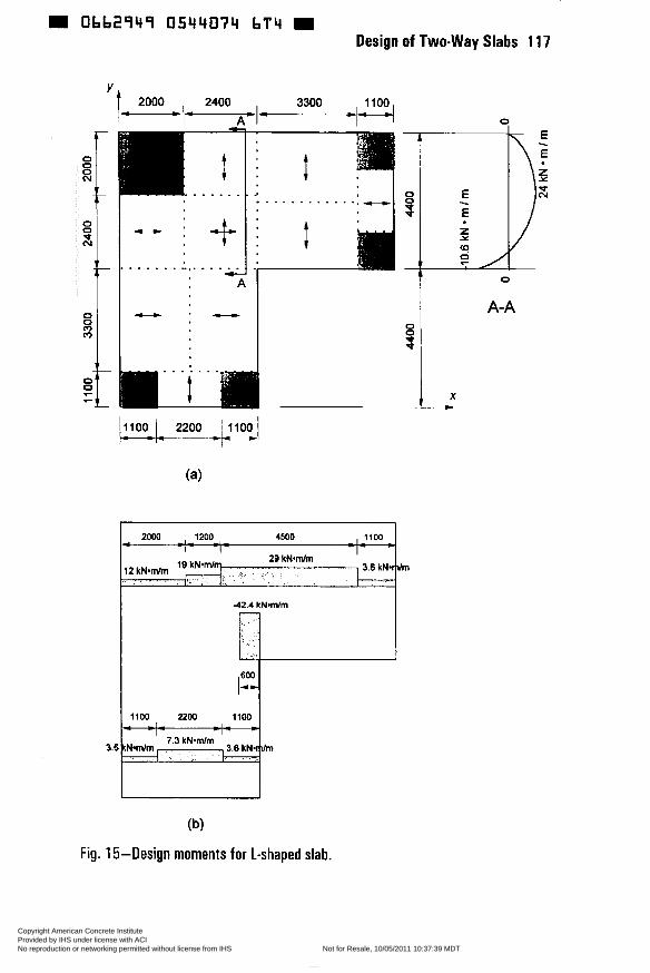
0bb2949 0544074 bT4
~
Design of Two-way Slabs 1 17
O O O N
o t N
O O (c> rn
O 4 7
2000 , 2400 3300 *=-I= -4 ..
. . . . . . . . . . .
I A-A
1200 4500
29 kN*mmi I
3.6 k N d m I ,
7.3 kN.mlm
(b)
Fig. 15-Design moments for 1-shaped slab.
Copyright American Concrete Institute Provided by IHS under license with ACI Licensee=AECOM User Geography and Business Line/5906698001, User=Elmorsi, Mostaf
Not for Resale, 10/05/2011 10:37:39 MDTNo reproduction or networking permitted without license from IHS
--`,``,,`,,`,,,,`,``,,,`,`,,,`,-`-`,,`,,`,`,,`---
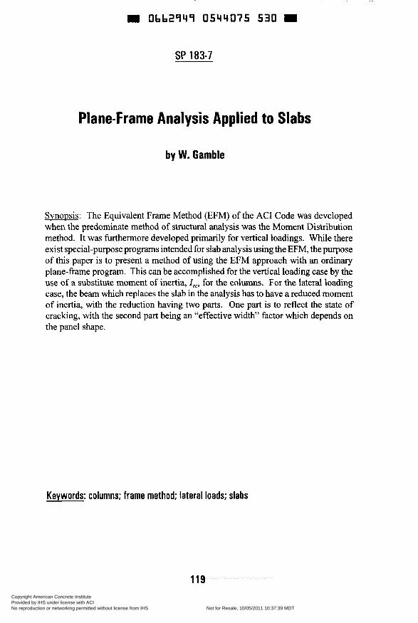
m Ob62949 0544075 530 m
SP 183-7
Plane-Frame Analysis Applied to Slabs
by W. Gamble
Svnopsis: The Equivalent Frame Method (EFM) of the AC1 Code was developed when the predominate method of structural analysis was the Moment Distribution method. It was furthermore developed primarily for vertical loadings. While there exist special-purpose programs intended for slab analysis using the EFM, the purpose of this paper is to present a method of using the EFM approach with an ordinary plane-frame program. This can be accomplished for the vertical loading case by the use of a substitute moment of inertia, I,,, for the columns. For the lateral loading case, the beam which replaces the slab in the analysis has to have a reduced moment of inertia, with the reduction having two parts. One part is to reflect the state of cracking, with the second part being an “effective width” factor which depends on the panel shape.
Keywords: columns; frame method; lateral loads; slabs
119 Copyright American Concrete Institute Provided by IHS under license with ACI Licensee=AECOM User Geography and Business Line/5906698001, User=Elmorsi, Mostaf
Not for Resale, 10/05/2011 10:37:39 MDTNo reproduction or networking permitted without license from IHS
--`,``,,`,,`,,,,`,``,,,`,`,,,`,-`-`,,`,,`,`,,`---
Obb2949 0544076 477 = 120 Gamble
AC1 Fellow William L. Gamble, Professor of Civil Engineering, has been a member of the faculty of the University of Illinois at Urbana-Champaign since 1963. He is engaged in teaching and research in the areas of reinforced and prestressed concrete. He is coauthor, with Robert Park, of a book on reinforced concrete slabs, and has published extensively.
PLANE-FRAME ANALYSIS APPLIED TO SLABS
The application of a plane-fiame analysis to a slab structure spanning in two directions sounds like an oxymoron. That is, of course, exactly what the “Equivalent Frame Method” analysis of the AC1 Codes has been doing for several decades, and the following are comments on how this can be done using whatever plane-frame program is available, rather than using a specialized slab program, or moment distribution methods. This is from the perspective of a low-tech computer user, recognizing that there are high-tech solutions using finite elements and other methods.
Different assumptions are needed when considering vertical and lateral loading cases, and they must be treated differently. For vertical loads, the primary interest is in the relative stiffnesses of the members. For lateral loads, one must have information on both the relative and absolute stiffnesses if one is to assess both the force distributions and displacements. In addition, the relative stiffnesses apparently must be quite different in the two cases. The original calibrations between analyses and experimental values of moment distributions were based on uncracked, gross section, Elvalues, as is still commonly done for the vertical loading case. The lateral loading case requires more complex evaluations of EI if the results are to be reasonable.
VERTICAL LOADING CASES
The Equivalent Frame Method (EFM) as included in the AC1 Code was formulated primarily for vertical load situations. The assumptions made about variations in member stiffnesses were thoroughly checked by Corley and Jirsa (1) against all data available at the time, and are believed to lead to reasonably accurate assessments of the moment distributions. The prevailing method of structural analysis at the time was the moment distribution method, and the EFM was made to fit into the moment distribution method. The horizontal members - slab-beams - and the vertical members - columns -are treated rather differently in any analysis.
Copyright American Concrete Institute Provided by IHS under license with ACI Licensee=AECOM User Geography and Business Line/5906698001, User=Elmorsi, Mostaf
Not for Resale, 10/05/2011 10:37:39 MDTNo reproduction or networking permitted without license from IHS
--`,``,,`,,`,,,,`,``,,,`,`,,,`,-`-`,,`,,`,`,,`---

obb2q4q 0544037 303 Design of Two-way Slabs 121
SLAB-BEAMS
The ACI EFM assigns a variable moment of inertia to the slab-beam components. In a frame analysis, the slab beam for a span is simply broken into several members as in Fig. 1. The moments of inertia are either I,,, or Is,J( 1 - cZ/ZJ2 as is appropriate to the segment. No more searching for the stiffness, fixed-end moment, and carry-over factors for anon-prismatic beam with stiffened end sections. And the moment at the node at the face of the column is the one which one wants for the slab reinforcement design, after division between the column and middle strips.
One caution is required at this point. The difference in stiffhess between the central member and the two short end members making up a span may be very great. In some cases this can introduce numerical instabilities which lead to erroneous results. In one classroom example, the same program gave correct results when all dimensions were in meters, and incorrect results when the dimensions were in mm. The incorrect solution resulted in beam end moments which were approximately the fixed end moments at all ends of all spans, regardless of the actual restraint conditions.
EQUIVALENT COLUMN STIFFNESS
The column stiffness is complex, on two bases. First, the end sections are assumed to be rigid for some distance. Second, a torsional member is interposed between the column and slab (for purposes of the analysis) (Fig. 2), and this member is thought of as being part of the column. The stiffness of this assembly is then taken as K,,, the stiffness of an equivalent column, defined as follows:
The derivation of Kec is of course well documented, but this stiffness value is of no help if you wish to use a plane-frame program, as opposed to a special purpose slab analysis program or moment distribution. K,, also has the problem of lumping together the combined stiffhesses of the columns above and below the slab, and these columns are of course often dissimilar.
The value of K,, can be subdivided between the two columns in the following manner:
Kc (Col. Above) For column above slab: Ke, = Ke,
XKc K, (Col. Below)
For column below slab: ICe: = K,, ZKC
This change, which was noted by Park and Gamble (2) , is helpful if you are doing the analysis by moment distribution, but not necessarily so for our plane-fi'ame
Copyright American Concrete Institute Provided by IHS under license with ACI Licensee=AECOM User Geography and Business Line/5906698001, User=Elmorsi, Mostaf
Not for Resale, 10/05/2011 10:37:39 MDTNo reproduction or networking permitted without license from IHS
--`,``,,`,,`,,,,`,``,,,`,`,,,`,-`-`,,`,,`,`,,`---
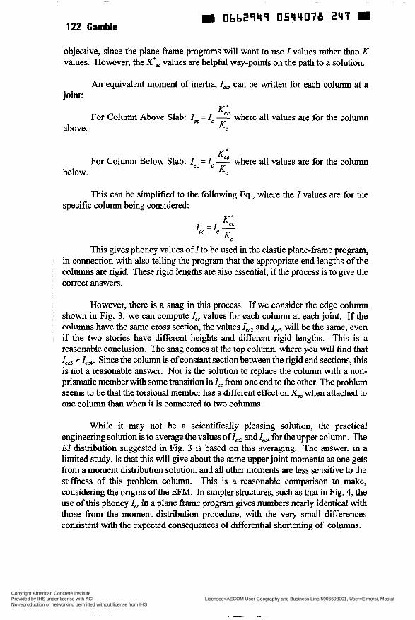
Ob62949 054ri078 2 4 T 122 Gamble
objective, since the plane frame programs will want to use I values rather than K values. However, the K',, values are helpful way-points on the path to a solution.
An equivalent moment of inertia, I,, can be written for each column at a joint:
Ke:
above. K C
For Column Above Slab: I,, = I, - where all values are for the column
KeL
below. KC For Column Below Slab: I,, = I, - where all values are for the column
This can be simplified to the following Eq., where the I values are for the specific column being considered:
This gives phoney values of I to be used in the elastic p l a n e - h e program, in connection with also telling the program that the appropriate end lengths of the columns are rigid. These rigid lengths are also essential, if the process is to give the correct answers.
However, there is a snag in this process. If we consider the edge column shown in Fig. 3, we can compute I,, values for each column at each joint. If the columns have the same cross section, the values I,, and Iec3 will be the same, even if the two stories have different heights and different rigid lengths. This is a reasonable conclusion. The snag comes at the top column, where you will find that Iec3 * Zed. Since the column is of constant section between the rigid end sections, this is not a reasonable answer. Nor is the solution to replace the column with a non- prismatic member with some transition in 1, from one end to the other. The problem seems to be that the torsional member has a different effect on 4, when attached to one column than when it is connected to two columns.
While it may not be a scientifically pleasing solution, the practical engineering solution is to average the values of Iec3 and Zed for the upper column. The EI distribution suggested in Fig. 3 is based on this averaging. The answer, in a limited study, is that this will give about the same upper joint moments as one gets from a moment distribution solution, and all other moments are less sensitive to the stiffness of this problem column. This is a reasonable comparison to make, considering the origins of the EFM. In simpler structures, such as that in Fig. 4, the use of this phoney I,, in a plane frame program gives numbers nearly identical with those from the moment distribution procedure, with the very small differences consistent with the expected consequences of differential shortening of columns.
Copyright American Concrete Institute Provided by IHS under license with ACI Licensee=AECOM User Geography and Business Line/5906698001, User=Elmorsi, Mostaf
Not for Resale, 10/05/2011 10:37:39 MDTNo reproduction or networking permitted without license from IHS
--`,``,,`,,`,,,,`,``,,,`,`,,,`,-`-`,,`,,`,`,,`---
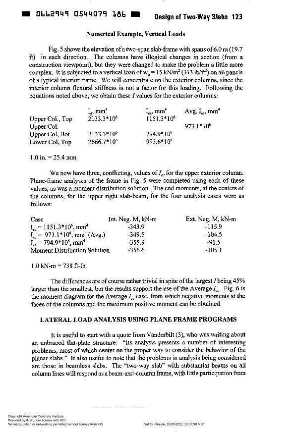
0662949 OClrY079 18b W Design of Two-way Slabs 123
Numerical Example, Vertical Loads
Fig. 5 shows the elevation of a two-span slab-frame with spans of 6.0 m (1 9.7 ft) in each direction. The columns have illogical changes in section (from a construction viewpoint), but they were changed to make the problem a little more complex. It is subjected to a vertical load of wu = 15 kN/m2 (3 13 lb/ft2) on all panels of a typical interior frame. We will concentrate on the exterior columns, since the interior column flexural stiffhess is not a factor for this loading. Following the equations noted above, we obtain these I values for the exterior columns:
I,, mm4 I,,, mm4 Avg. I,,, mm4 Upper Col., Top 2133.3*106 1151.3*106 Upper Col. 973.1* lo6
Lower Col, Top 2666.7*106 993.6* 1 O6 Upper Col, Bot. 2 133.3* 1 O6 794.9* lo6
1 .O in. = 25.4 mrn
We now have three, conflicting, values of I,, for the upper exterior column. Plane-frame analyses of the frame in Fig. 5 were completed using each of these values, as was a moment distribution solution. The end moments, at the centers of the columns, for the upper right slab-beam, for the four analysis cases were as follows:
Case Int. Neg. M, kN-m Ext. Neg. M, kN-m Iec= 1151.3*106,mm4 -343.9 -115.9 I,, = 973.1 * lo6, mm4 (Avg.) -349.5 -104.5 I,, = 794.9* lo6, mm4 -355.9 -91.5 Moment Distribution Solution -356.6 -105.1
1 .O kN-m = 738 fi-lb
The differences are of course rather trivial in spite of the largest I being 45% larger than the smallest, but the results support the use of the Average Zec. Fig. 6 is the moment diagram for the Average I,, case, from which negative moments at the faces of the columns and the maximum positive moment can be obtained.
LATERAL LOAD ANALYSIS USING PLANE FRAME PROGRAMS
It is useful to start with a quote from Vanderbilt (3), who was writing about an unbraced flat-plate structure: “Its analysis presents a number of interesting problems, most of which center on the proper way to consider the behavior of the planar slabs.” It also useful to note that the problems in analysis being considered are those in beamless slabs. The “two-way slab” with substantial beams on all column lines will respond as a beam-and-column frame, with little participation from
Copyright American Concrete Institute Provided by IHS under license with ACI Licensee=AECOM User Geography and Business Line/5906698001, User=Elmorsi, Mostaf
Not for Resale, 10/05/2011 10:37:39 MDTNo reproduction or networking permitted without license from IHS
--`,``,,`,,`,,,,`,``,,,`,`,,,`,-`-`,,`,,`,`,,`---
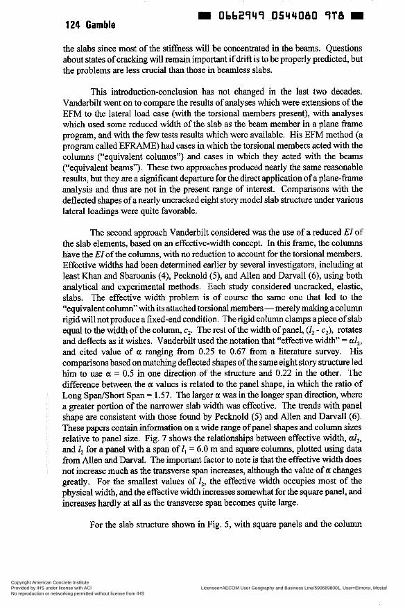
Obb2îriî 05ri4080 î T 8 D 124 Gamble
the slabs since most of the stiffness will be concentrated in the beams. Questions about states of cracking will remain important if drift is to be properly predicted, but the problems are less crucial than those in beamless slabs.
This introduction-conclusion has not changed in the last two decades. Vanderbilt went on to compare the results of analyses which were extensions of the EFM to the lateral load case (with the torsional members present), with analyses which used some reduced width of the slab as the beam member in a plane frame program, and with the few tests results which were available. His EFM method (a program called EFRAME) had cases in which the torsional members acted with the columns (“equivalent columns”) and cases in which they acted with the beams (“equivalent beams”). These two approaches produced nearly the same reasonable results, but they are a significant departure for the direct application of a plane-fi-ame analysis and thus are not in the present range of interest. Comparisons with the deflected shapes of a nearly uncracked eight story model slab structure under various lateral loadings were quite favorable.
The second approach Vanderbilt considered was the use of a reduced EI of the slab elements, based on an effective-width concept. In this frame, the columns have the EI of the columns, with no reduction to account for the torsional members. Effective widths had been determined earlier by several investigators, including at least Khan and Sbarounis (4), Pecknold (5 ) , and Allen and Darvall(6), using both analytical and experimental methods. Each study considered uncracked, elastic, slabs. The effective width problem is of course the same one that led to the “equivalent column” with its attached torsional members -merely making a column rigid will not produce a fixed-end condition. The rigid column clamps apiece of slab equal to the width of the column, c2. The rest of the width of panel, (12 - c2), rotates and deflects as it wishes. Vanderbilt used the notation that “effective width” = al2, and cited value of a ranging from 0.25 to 0.67 from a literature survey. His comparisons based on matching deflected shapes of the same eight story structure led him to use a = 0.5 in one direction of the structure and 0.22 in the other. The difference between the a values is related to the panel shape, in which the ratio of Long SpaníShort Span = 1.57. The larger a was in the longer span direction, where a greater portion of the narrower slab width was effective. The trends with panel shape are consistent with those found by Pecknold (5) and Allen and Darvall(6). These papers contain information on a wide range of panel shapes and column sizes relative to panel size. Fig. 7 shows the relationships between effective width, al,, and Z2 for a panel with a span of I , = 6.0 m and square columns, plotted using data from Allen and Darval. The important factor to note is that the effective width does not increase much as the transverse span increases, although the value of a changes greatly. For the smallest values of Z2, the effective width occupies most of the physical width, and the effective width increases somewhat for the square panel, and increases hardly at all as the transverse span becomes quite large.
For the slab structure shown in Fig. 5, with square panels and the column
Copyright American Concrete Institute Provided by IHS under license with ACI Licensee=AECOM User Geography and Business Line/5906698001, User=Elmorsi, Mostaf
Not for Resale, 10/05/2011 10:37:39 MDTNo reproduction or networking permitted without license from IHS
--`,``,,`,,`,,,,`,``,,,`,`,,,`,-`-`,,`,,`,`,,`---
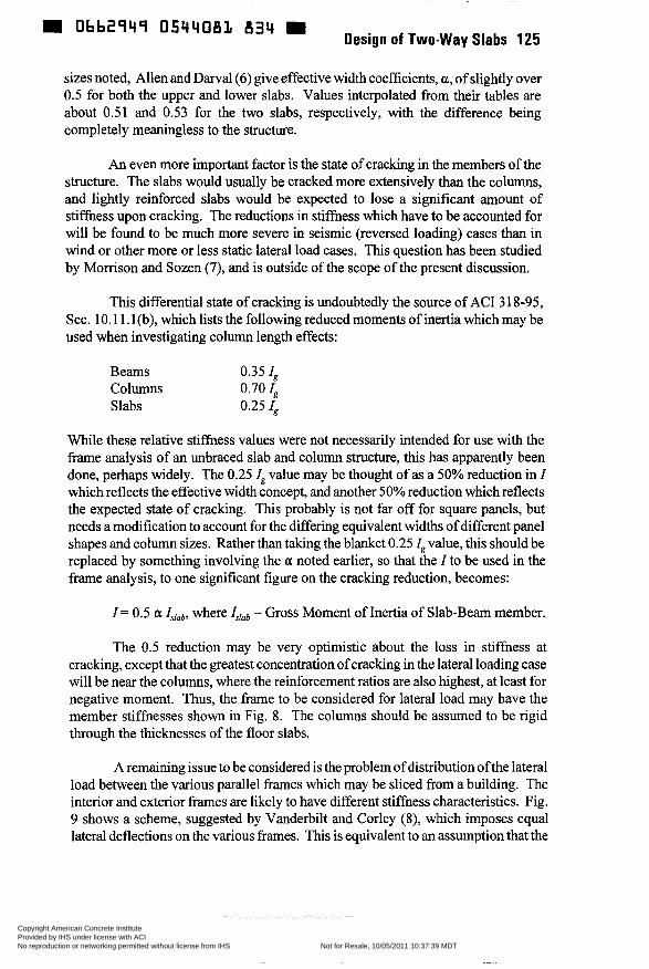
0bb2q4q 834 Design of Two-way Slabs 125
sizes noted, Allen and Darval (6) give effective width coefficients, a, of slightly over 0.5 for both the upper and lower slabs. Values interpolated from their tables are about 0.51 and 0.53 for the two slabs, respectively, with the difference being completely meaningless to the structure.
An even more important factor is the state of cracking in the members of the structure. The slabs would usually be cracked more extensively than the columns, and lightly reinforced slabs would be expected to lose a significant amount of stiffness upon cracking. The reductions in stiffness which have to be accounted for will be found to be much more severe in seismic (reversed loading) cases than in wind or other more or less static lateral load cases. This question has been studied by Morrison and Sozen (7), and is outside of the scope of the present discussion.
This differential state of cracking is undoubtedly the source of AC1 3 18-95, Sec. 1 O. 1 1.1 (b), which lists the following reduced moments of inertia which may be used when investigating column length effects:
Beams 0.35 I, Columns 0.70 I, Slabs 0.25 I,
While these relative stiffness values were not necessarily intended for use with the frame analysis of an unbraced slab and column structure, this has apparently been done, perhaps widely. The 0.25 Z, value may be thought of as a 50% reduction in Z which reflects the effective width concept, and another 50% reduction which reflects the expected state of cracking. This probably is not far off for square panels, but needs a modification to account for the differing equivalent widths of different panel shapes and column sizes. Rather than taking the blanket 0.25 Z, value, this should be replaced by something involving the o: noted earlier, so that the Z to be used in the frame analysis, to one significant figure on the cracking reduction, becomes:
I = 0.5 a Is[& where Ir,ab = Gross Moment of Inertia of Slab-Beam member.
The 0.5 reduction may be very optimistic about the loss in stiffness at cracking, except that the greatest concentration of cracking in the lateral loading case will be near the columns, where the reinforcement ratios are also highest, at least for negative moment. Thus, the frame to be considered for lateral load may have the member stiffnesses shown in Fig. 8. The columns should be assumed to be rigid through the thicknesses of the floor slabs.
A remaining issue to be considered is the problem of distribution ofthe lateral load between the various parallel frames which may be sliced from a building. The interior and exterior frames are likely to have different stiffness characteristics. Fig. 9 shows a scheme, suggested by Vanderbilt and Corley (8), which imposes equal lateral deflections on the various frames. This is equivalent to an assumption that the
Copyright American Concrete Institute Provided by IHS under license with ACI Licensee=AECOM User Geography and Business Line/5906698001, User=Elmorsi, Mostaf
Not for Resale, 10/05/2011 10:37:39 MDTNo reproduction or networking permitted without license from IHS
--`,``,,`,,`,,,,`,``,,,`,`,,,`,-`-`,,`,,`,`,,`---
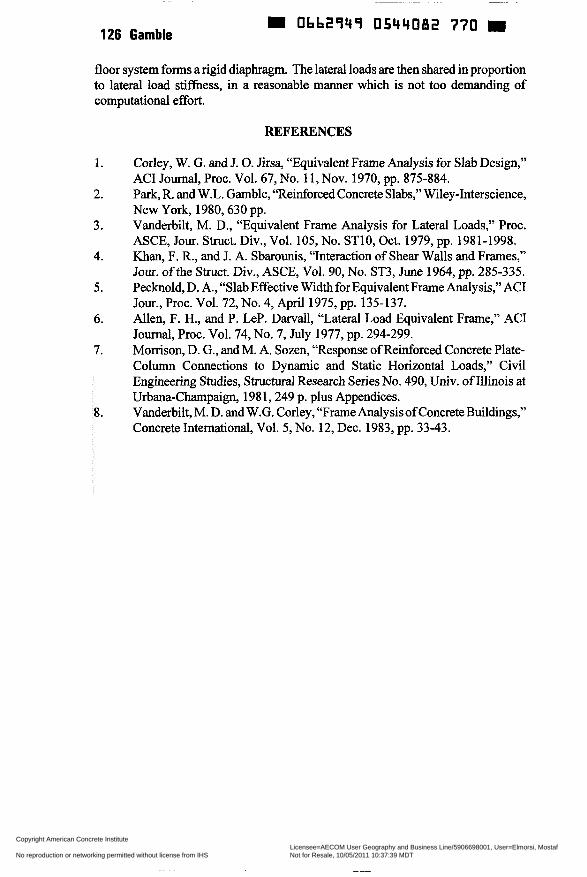
126 Gamble 0bb2949 0544082 770
floor system forms a rigid diaphragm. The lateral loads are then shared in proportion to lateral load stiffness, in a reasonable manner which is not too demanding of computational effort.
REFERENCES
1 .
2.
3.
4.
5.
6.
7.
8.
Corley, W. G. and J. O. Jirsa, “Equivalent Frame Analysis for Slab Design,” AC1 Journal, Proc. Vol. 67, No. 1 1 , Nov. 1970, pp. 875-884. Park, R. and W.L. Gamble, “Reinforced Concrete Slabs,” Wiley-Interscience, New York, 1980,630 pp. Vanderbilt, M. D., “Equivalent Frame Analysis for Lateral Loads,” Proc. ASCE, Jour. Stnict. Div., Vol. 105,No. STlO, Oct. 1979, pp. 1981-1998. Khan, F. R., and J. A. Sbarounis, “Interaction of Shear Walls and Frames,” Jour. ofthe Struct. Div., ASCE, Vol. 90, No. ST3, June 1964, pp. 285-335. Pecknold, D. A., “Slab Effective Width for Equivalent Frame Analysis,” AC1 Jour., Proc. Vol. 72, No. 4, April 1975, pp. 135-137. Allen, F. H., and P. LeP. Darvall, “Lateral Load Equivalent Frame,” AC1 Journal, Proc. Vol. 74, No. 7, July 1977, pp. 294-299. Morrison, D. G., and M. A. Sozen, “Response of Reinforced Concrete Plate- Column Connections to Dynamic and Static Horizontal Loads,” Civil Engineering Studies, Structural Research Series No. 490, Univ. of Illinois at Urbana-Champaign, 198 1,249 p. plus Appendices. Vanderbilt, M. D. and W.G. Corley, “Frame Analysis of Concrete Buildings,” Concrete International, Vol. 5, No. 12, Dec. 1983, pp. 33-43.
Copyright American Concrete Institute Provided by IHS under license with ACI Licensee=AECOM User Geography and Business Line/5906698001, User=Elmorsi, Mostaf
Not for Resale, 10/05/2011 10:37:39 MDTNo reproduction or networking permitted without license from IHS
--`,``,,`,,`,,,,`,``,,,`,`,,,`,-`-`,,`,,`,`,,`---
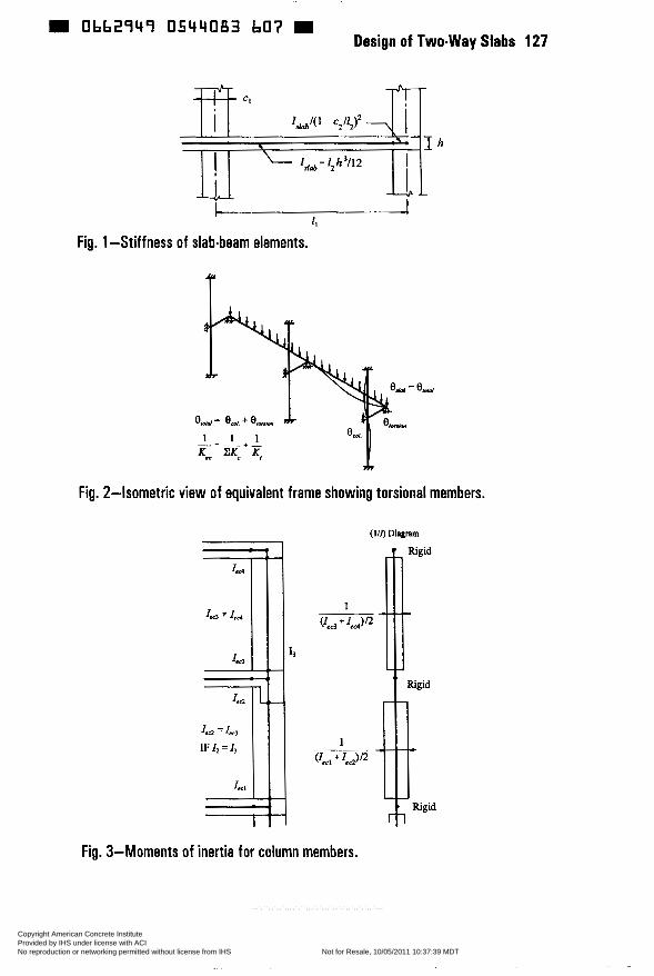
= 0662949 0544083 607 Design of Two-way Slabs 127
1,
Fig. 1 -Stiffness of slab-beam elements.
T
= +
K e K, A
Fig. 2-Isometric view of equivalent frame showing torsional members.
Fig. 3-Moments of inertia for column members.
Copyright American Concrete Institute Provided by IHS under license with ACI Licensee=AECOM User Geography and Business Line/5906698001, User=Elmorsi, Mostaf
Not for Resale, 10/05/2011 10:37:39 MDTNo reproduction or networking permitted without license from IHS
--`,``,,`,,`,,,,`,``,,,`,`,,,`,-`-`,,`,,`,`,,`---
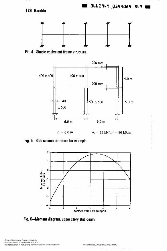
128 Gamble
t
200 mm
I
500 x 500
+7
Obb2949 O544084 543
Fig. 4-Simple equivalent frame structure.
400x400
*
400 x 400 El FI I
A 6.0 m
l2 = 6.0 m
Fig. 5-Slab-column structure for example.
2
1
-3
4
4.0 m
5.0 m
-I
6.0 m
W, = i 5 iCN/m* = 9O kN/m
O 1 2 3 4 5 6 Meters from Lefl Support
Fig. 6-Moment diagram, upper story slab-beam.
Copyright American Concrete Institute Provided by IHS under license with ACI Licensee=AECOM User Geography and Business Line/5906698001, User=Elmorsi, Mostaf
Not for Resale, 10/05/2011 10:37:39 MDTNo reproduction or networking permitted without license from IHS
--`,``,,`,,`,,,,`,``,,,`,`,,,`,-`-`,,`,,`,`,,`---
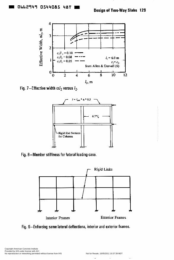
0bb2q4q 0544085 48T Design of Two-way Slabs 129
O 2 4 6 8 1 0 1 2
h, m Fig. 7-Effective width alp versus 12.
Fig. 8-Member stiffness for lateral loading case.
r Rigid Li*s
Interior Frames Exterior Frames
Fig. 9-Enforcing same lateral deflections, interior and exterior frames.
Copyright American Concrete Institute Provided by IHS under license with ACI Licensee=AECOM User Geography and Business Line/5906698001, User=Elmorsi, Mostaf
Not for Resale, 10/05/2011 10:37:39 MDTNo reproduction or networking permitted without license from IHS
--`,``,,`,,`,,,,`,``,,,`,`,,,`,-`-`,,`,,`,`,,`---
0662949 0544086 316
SP 183-8
Detailing for Serviceability
by O. Rogowsky
Svnousis: This paper deals with the selection c, slab reinforcement and details from the perspective of serviceability. The focus is on extending traditional detailing rules to slabs with higher strength concrete, and to slab designs based on finite element analysis. Traditional detailing rules when used with the direct design method and equivalent frame method produce satisfactory slabs for "ordinary" applications. Slabs that fall outside the limits of applicability of the equivalent frame method are becoming more common due to the relatively ease with which one can obtain a finite element solution for elastic bending moments and forces. Detailing rules need to be generalized to deal with higher strength concrete and the results of a finite element analysis, so that one can select reinforcement that provides adequate strength and serviceability. The issues addressed in this paper include: minimum reinforcement requirements; bar size, spacing and layout; bars oriented in non-principal moment directions; skew reinforcement; in-plane forces; and edge reinforcement. While there are other detailing issues, those discussed tend to have the most impact on slab performance and cost.
Keywords: detailing; finite element analysis; reinforced concrete design; slabs
131 Copyright American Concrete Institute Provided by IHS under license with ACI Licensee=AECOM User Geography and Business Line/5906698001, User=Elmorsi, Mostaf
Not for Resale, 10/05/2011 10:37:39 MDTNo reproduction or networking permitted without license from IHS
--`,``,,`,,`,,,,`,``,,,`,`,,,`,-`-`,,`,,`,`,,`---
Obb2949 0544087 252 132 Rogowsky
D. M. Rogowsky has been involved in the design and construction of concrete structures since 1973. As a practicing structural engineer, he was involved in the design and construction of numerous structures where ordinary slab design and detailing rules where not applicable. He is currently a Professor at the University of Alberta.
INTRODUCTION
This paper deals with the selection of slab reinforcement and details from the perspective of serviceability. The focus is on extending traditional detailing rules to slabs with higher strength concrete, and to slab designs based on finite element analysis. Traditional detailing rules when used with the direct design method and equivalent frame method produce satisfactory slabs for "ordinary" applications. Slabs that fall outside the limits of applicability of the equivalent frame method are becoming more common due to the relatively ease with which one can obtain a finite element solution for elastic bending moments and forces. Detailing rules need to be generalized to deal with higher strength concrete and the results of a finite element analysis, so that one can select reinforcement that provides adequate strength and serviceability.
The issues addressed in this paper include: minimum reinforcement requirements; bar size, spacing and layout; bars oriented in non-principal moment directions; skew reinforcement; in-plane forces; and edge reinforcement. While not all detailing issues are addressed, these tend to have the most impact on slab performance and cost. It turns out that plasticity theory is of considerable assistance in extending the detailing rules.
MINIMUM REINFORCEMENT REQUIREMENTS
All slabs should be provided with enough reinforcement to keep crack widths within acceptable limits. This is currently done through the provision of minimum shrinkage and temperature reinforcement. For Grade 60 reinforcement, AC1 318-95 [l] requires:
&,,,," = 0.0018bh
This is empirically based and has given satisfactory performance for concrete strengths of approximately 3000 psi, and slabs without "significant restraint". Clause 7.12.1.2, introduced in the 1995 edition of AC1 318, warns that additional reinforcement may be required when movements due to shrinkage and temperature changes are restrained by
Copyright American Concrete Institute Provided by IHS under license with ACI Licensee=AECOM User Geography and Business Line/5906698001, User=Elmorsi, Mostaf
Not for Resale, 10/05/2011 10:37:39 MDTNo reproduction or networking permitted without license from IHS
--`,``,,`,,`,,,,`,``,,,`,`,,,`,-`-`,,`,,`,`,,`---
0bb2q4q 054408* Iqq Design of Two-way Slabs 133
structural walls or large columns. As will be shown below, the minimum reinforcement required for satisfactory slab performance may be two to three times that given by Eq. 1.
The first improvement on Eq. 1 is to recognize, at least approximately, the degree of shrinkage restraint that one has. Some guidance can be found in AC1 350R-89 [2]. This report deals with the design of liquid containing structures such as water reservoirs and sewage treatment tanks where crack control is particularly important. For Grade 60 reinforcement, AC1 350R gives the minimum shrinkage and temperature reinforcement as a function of the distance between shrinkage dissipating joints as shown in Fig. 1. For shrinkage dissipating joints at a spacing of 60 or more feet, A,,, = 0.005bh. With closer joint spacing, the shrinkage restraint is reduced, and the recommended minimum area of steel is reduced; but, the report recommends at least 0.003bh. When one has severe exposure conditions and crack control is critical, this minimum should be used in preference to that given in Eq. I.
The author has used Fig. 1 as the design basis for ice hockey rink slabs. These are approximately 220 feet by 85 feet, and are cast in one placement without joints. Crack control requirements are more severe than an ordinary ofice building because of the damage that can be caused by water freezing in the cracks. Experience with six slabs indicates that a steel ratio of 0.005 sometimes gives a visible crack near mid-length that has a crack width of approximately 0.012". A steel ratio of 0.006 limits cracks to hairline width. Figure 2 shows a common example of a highly restrained slab. When slabs are cast against, and dowelled to, previously placed concrete walls, one gets shrinkage cracks perpendicular to the wall as shown. These cracks can be controlled by using a steel ratio of approximately 0.005 parallel to the walls in the half panels adjacent to the walls. This level of crack control is particularly important for slabs that are used for underground parking in areas where cars bring in chloride laden snow (road de-icing salts) on their undercarriage.
Equation 1, and Fig. 1 are empirically based. There is a need for a rational analysis so that minimum reinforcement requirements can be estimated for situations not envisioned in AC1 31 8, and AC1 350R. What follows is a rational analysis that at least approximately accounts for all of the important variables.
The starting premise is that we wish to prevent large cracks and, if the steel does not yield, the cracks do not become large. Prior to cracking, the concrete resists most of the force in a reinforced concrete slab. This can be confirmed by analysis with an elastic transformed section. After cracking, most of the tension force is resisted by the steel. This can be
Copyright American Concrete Institute Provided by IHS under license with ACI Licensee=AECOM User Geography and Business Line/5906698001, User=Elmorsi, Mostaf
Not for Resale, 10/05/2011 10:37:39 MDTNo reproduction or networking permitted without license from IHS
--`,``,,`,,`,,,,`,``,,,`,`,,,`,-`-`,,`,,`,`,,`---
Obb2949 0544089 025 m 134 Rogowsky
confirmed by analysis with a cracked transformed section. From this, it can be concluded that large cracks can be prevented if the area of steel provided is sufficient to take over the tensile force from the concrete without yielding.
Higher concrete tensile strength results in larger tensile forces in the concrete at cracking, and hence requires an increased minimum reinforcement. To predict the concrete tensile stress at rupture, one might be tempted to use the equation:
f, = 7.5K
Equation 2 is based on AC1 318 Clause 9.5.2.3. This however tends to overestimate the concrete tensile strength at cracking. When shrinkage is restrained, concrete tensile stresses and tensile strength both start from zero when the concrete is cast, and increase with time. Cracking occurs when the tensile stresses equal the tensile strength. This may occur well before the concrete reaches its 28 day strength. The Swiss concrete design standard [3] suggests that the concrete tensile stress at cracking is:
f, = 290 psi for f, c 3600 psi fa = 360 psi for f, 2 3600 psi
The values from Eq. 3 are significantly lower than the value from Eq. 2, and are believed to be more appropriate for real structures.
A larger concrete tensile stress block produces a larger tensile force at cracking, and hence requires more minimum reinforcement. When concrete slabs are subjected to flexure, half of the cross-section is in tension, with zero tensile stress at the centroid and f, at the extreme fiber in tension. When concrete slabs are subjected to direct tension, the full cross-section is in tension and all areas are subjected to f,. In thicker slabs, the size effect, and the residual stresses in the concrete due to moisture and thermal gradients reduce the average stress in the concrete at cracking. Figure 3 illustrates the area of concrete in tension &, and ß, the ratio of the average tensile stress in the concrete at cracking to the maximum concrete tensile stress at cracking.
The effectiveness of reinforcing bars at controlling crack widths is a function of bar spacing. The more widely the bars are spaced, the less effective they are at controlling cracks. Hence, for the same degree of
Copyright American Concrete Institute Provided by IHS under license with ACI Licensee=AECOM User Geography and Business Line/5906698001, User=Elmorsi, Mostaf
Not for Resale, 10/05/2011 10:37:39 MDTNo reproduction or networking permitted without license from IHS
--`,``,,`,,`,,,,`,``,,,`,`,,,`,-`-`,,`,,`,`,,`---
0bb2q4q 05440q0 847 Design of Two-way Slabs 135
crack control, a larger area of steel is required when bars are widely spaced. This may be accounted for with a bar spacing factor a, as shown in Table 1.
Setting the tensile force in the concrete at cracking equal to the yield force in the reinforcement one obtains:
Solving Eq. 4 for A,,,, gives:
For ordinary applications, Eq. 5 gives values of A,,,, that are very similar to those required by AC1 318. For example, a 6 inch thick 3000 psi concrete slab that is subjected primarily to flexure when it cracks and is reinforced with Grade 60 bars at a spacing of 12 or more inches on center requires:
A,,,, = aß&fdfy = 1.4x0.5x(6x12/2)x290/60,000 = 0.122 in2/ft width
Using #4@20"0/c, A,,,i,,/bh = 0.0017
Equation 5 can be used to estimate the minimum reinforcement required for crack control for special applications not covered by AC1 318. For example, a 6 inch thick 4500 psi concrete slab restrained by a shear wall (primarily direct tension when slab cracks) and is reinforced with Grade 60 bars at a spacing of 8 inches on center requires:
A,,,, = aß&fJfy = I .2x0.85x(6x12)x360/60,000 = 0.44 in% width
Using #5@8"0/c, &,,in/bh = 0.0061
Equation 5 is suggested as a provisional equation for determining the minimum reinforcement required for crack control for special situations. Examples of these special situations include: presence of significant shrinkage restraint; use of high strength concrete; and when stringent control of crack widths is required for durability or aesthetic reasons. Further study is undoubtedly warranted.
Copyright American Concrete Institute Provided by IHS under license with ACI Licensee=AECOM User Geography and Business Line/5906698001, User=Elmorsi, Mostaf
Not for Resale, 10/05/2011 10:37:39 MDTNo reproduction or networking permitted without license from IHS
--`,``,,`,,`,,,,`,``,,,`,`,,,`,-`-`,,`,,`,`,,`---
m Obb2949 054409L 783 W 136 Rogowsky
BAR SIZE, SPACING AND LAYOUT
Bars used in top mats should be large enough to walk on. Top mats with #3 bars are easily damaged by foot traffic unless very well supported. When a worker steps on a #3 bar in the top mat, it usually becomes bent and positioned lower than intended. This can result in a significant reduction in negative moment capacity. The minimum bar size for top mats should be at least #4, and preferably #5. Bottom mat reinforcing is typically less susceptible to damage. When a worker steps on a #3 bar in the bottom mat, it usually deflects elastically until it comes into contact with the form. When the worker steps off of the bar, it springs back to its original position, and no harm is done. Adequate bar supports for both the top and bottom mats are of course required.
Small diameter closely spaced bars are desirable for crack control, but they have a higher installed cost per ton than fewer large diameter bars at a wider spacing. The historic spacing limits for shrinkage and temperature reinforcement of five times the slab thickness but not more than 18 inches have proven to be satisfactory of ordinary applications. For special applications where Eq. 5 is used to determine minimum reinforcement, the bar spacing factor a will lead to minimum cost solutions with closer bar spacing than current maximum limits.
The layout of the bars should be as simple as possible. The bar layout should of course provide adequate positive and negative moment capacity. Since flexural failure of a slab occurs with yield lines crossing column and middle strips, the layout of reinforcement can be somewhat simpler than suggested by AC1 318, Chapter 13. The bottom mat can be essentially uniform, while the top mat can consist of top mats over the columns only. Cardenas and Kaar [4] describe load tests on a structure that show little difference in performance between a slab detailed as suggested above and a slab detailed in accordance with AC1 31 8 Chapter 13. Figure 4 compares the reinforcement layouts. The AC1 distribution of reinforcement locates bars in amounts proportional to the moments from an elastic analysis. Since elastic moments are proportional to the elastic curvature, locating top bars in the middle strip where curvatures are small produces little stress in the reinforcement. Large deformations are required to get enough curvature in the middle strip to yield the top reinforcement. The relocation of the top bars from the middle strip into the column strip is beneficial because it shifts these bars into a region of greater slab curvature. The strength of these bars can therefore be mobilized without large inelastic deformations. When special crack control is required, top steel should also be provided in the middle strip. This steel is proportioned for crack control rather than moment resistance.
Copyright American Concrete Institute Provided by IHS under license with ACI Licensee=AECOM User Geography and Business Line/5906698001, User=Elmorsi, Mostaf
Not for Resale, 10/05/2011 10:37:39 MDTNo reproduction or networking permitted without license from IHS
--`,``,,`,,`,,,,`,``,,,`,`,,,`,-`-`,,`,,`,`,,`---
Design of Two-way Slabs 137 = Obb2949 O544092 b l T
When supporting concentrated loads, or dealing with unusual geometry, it is often desirable to place the reinforcement in bands. If the slab has been analyzed by the finite element method, one will generally find that the factored moment demand varies continuously across a panel as shown in Fig. 5. It is not practical and not necessary to continuously vary the bar spacing to match the moment demand. The reinforcement may be placed in bands with a uniform spacing in each band such that the maximum moment in a band does not exceed 1.5 times the average moment in the band. The total moment capacity provided in each band, should equal or exceed the total moment demand over the width of the band.
BARS NOT IN PRINCIPAL DIRECTIONS
For ordinary structures that fall within the limitations of applicability of the equivalent frame method, the critical sections for positive and negative moments are in principal moment directions. That is, twisting moments are essentially zero at the critical sections. For general slabs that do not behave as orthogonal frames, orthogonal reinforcement will not necessarily be in the principal moment directions. Nielsen [5] used plasticity to determine the equivalent design moments for the design of reinforcement when normal moments are accompanied by twisting moments. The solution is given in Fig. 6. The coefficients k, and k, can theoretically be any positive number. Usually, they are taken as 1 .O. The algorithm shown in Fig. 6 can be used to convert the results of an elastic analysis into equivalent moments for bars placed parallel to the x and y axes. Figure 7 shows a example of a circular slab, where the principal moments are in the radial and tangential directions but the reinforcement is placed in x and y directions.
SKEW REINFORCEMENT
For skew slabs, such as the one shown in Fig. 8, it is sometimes desirable to place skew rather than orthogonal reinforcement. Hillerborg [6] extended the work of Nielson as shown in Fig. 9. Note that in his solution, x and y are skew coordinate directions.
IN-PLANE FORCES AND OUT OF PLANE SHEAR FORCES
In addition to the two normal moments m, and my and the twisting moment mv, there can be in-plane normal stress resultants n,, and ny and an in- plane shear stress resultant of nv, as well as ordinary out of plane shears of v, and v,. These eight stress resultants are shown in Fig. lO(a). Marti [7] used plasticity and the sandwich model shown in Fig. 1 O(b) to develop
Copyright American Concrete Institute Provided by IHS under license with ACI Licensee=AECOM User Geography and Business Line/5906698001, User=Elmorsi, Mostaf
Not for Resale, 10/05/2011 10:37:39 MDTNo reproduction or networking permitted without license from IHS
--`,``,,`,,`,,,,`,``,,,`,`,,,`,-`-`,,`,,`,`,,`---
D Obb2949 0544093 55b 138 Rogowsky
expressions for the required reinforcement in x and y directions for the top and bottom mats. The reader is referred to the original work by Marti for the detailed expressions. They permit one to dimension reinforcement for the eight stress resultants that one might obtains from a general three dimensional finite element analysis.
EDGE REINFORCEMENT
The twisting moment in a slab, m,, is analogous to torsion in a beam as shown in Fig. 11. One should reinforce the slab edge like one would reinforce the side face of a beam in torsion when m, is significant. For ordinary structures that fall within the limitations of applicability of the equivalent frame method, slab edges are in principal moment directions. That is, twisting moments are essentially zero, and slab edge reinforcement is not required. In structures where the yield lines intersect the slab edge at an angle other than 90 degrees, it is an indication that the twisting moments are significant and that slab edge reinforcement is required. Marti [7] gives the solution for the amount of edge reinforcement required. It is sufficient to provide U-bars as shown in Fig. 11 of a size and spacing that match, and lap with, the top and bottom slab bars.
SUMMARY
AC1 318 is sufficient for ordinary slabs, but provides little guidance for slabs that fall outside the scope of the direct design and equivalent frame methods. This paper has attempted to collect and present the design tools required for general slab design.
REFERENCES
1. AC1 Committee 318, "Building Code Requirements for Structural Concrete (AC1 318-95)," American Concrete Institute, Farmington Hills, MI, 1995.
2. AC1 Committee 350, "Environmental Engineering Concrete Structures (AC1 350R-89)," American Concrete Institute, Detroit, 1989.
3. "Betonbauten, SIA Norm 162 (i 989)", Schweizerischer Ingenieur und Architekten Verein, Zurich, 1989.
4. Cardenas A.E., and Kaar, P.H., "Field Test of a Flat Plate Structure," AC1 Journal, Proceedings, V. 68, No. 1, January, 1971, pp. 50-59.
5. Nielsen, M.P., "Limit Analysis and Concrete Plasticity", Prentice-Hall, New Jersey, 1984,420 pp.
Copyright American Concrete Institute Provided by IHS under license with ACI Licensee=AECOM User Geography and Business Line/5906698001, User=Elmorsi, Mostaf
Not for Resale, 10/05/2011 10:37:39 MDTNo reproduction or networking permitted without license from IHS
--`,``,,`,,`,,,,`,``,,,`,`,,,`,-`-`,,`,,`,`,,`---

= Obbt949 0544094 492 Design of Two-way Slabs 139
6. Hillerborg, A., "Strip Method of Design", Viewpoint Publication, Cement and Concrete Association, Wexham Springs, England, 1975, 256 pp.
7. Marti, P., "Design of Concrete Slabs for Transverse Shear," AC1 Structural Journal, V. 87, No. 2, March-April 1990, pp. 180-190.
Copyright American Concrete Institute Provided by IHS under license with ACI Licensee=AECOM User Geography and Business Line/5906698001, User=Elmorsi, Mostaf
Not for Resale, 10/05/2011 10:37:39 MDTNo reproduction or networking permitted without license from IHS
--`,``,,`,,`,,,,`,``,,,`,`,,,`,-`-`,,`,,`,`,,`---
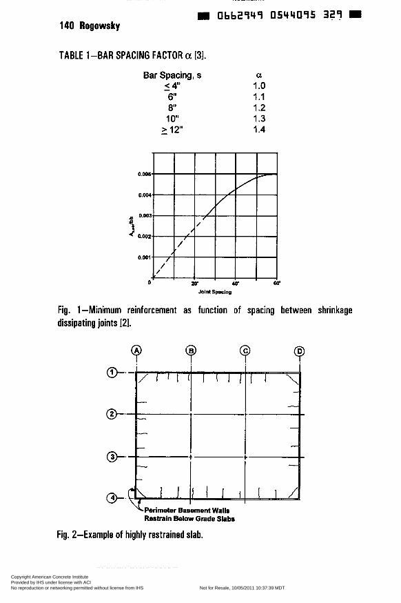
Obb2949 0544095 329 140 Rogowsky
0 . W
0.004.
0.003.
3 0.002..
0.Ooi.
TABLE 1-BAR SPACING FACTOR a [31.
/ / /
/ , I
/ / ,
/ /
Bar Spacing, s < 4" 6 8 , Io" - > 12"
- a 1 .o 1.1 1.2 1.3 1.4
w 60' Joint Spacing
Fig. 1 -Minimum reinforcement as function of spacing between shrinkage dissipating joints 121.
\Perimeter Basement Walls Restrain Below Grade Slabs
Fig. 2-Example of highly restrained slab.
Copyright American Concrete Institute Provided by IHS under license with ACI Licensee=AECOM User Geography and Business Line/5906698001, User=Elmorsi, Mostaf
Not for Resale, 10/05/2011 10:37:39 MDTNo reproduction or networking permitted without license from IHS
--`,``,,`,,`,,,,`,``,,,`,`,,,`,-`-`,,`,,`,`,,`---
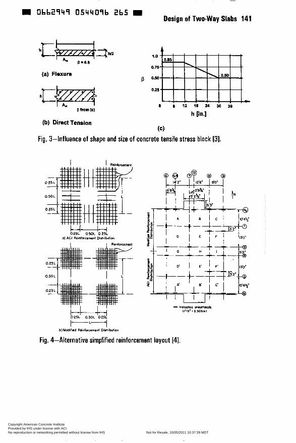
Obb2949 054409b 2b5 R Design of Two-way Slabs 141
(a) Flexure ß
h [in.] (b) Direct Tension
(cl Fig. 3-Influence of shape and size of concrete tensile stress block [3].
t t t I Reinfoi-t
D25L O W L 025L a) AGI Reinforcement Disinbdion
I 1 Reinfncemot
ILI b l Medifiad Reinfwcemcd Distribution
Fig. 4-Alternative simplified reinforcement layout [4].
Copyright American Concrete Institute Provided by IHS under license with ACI Licensee=AECOM User Geography and Business Line/5906698001, User=Elmorsi, Mostaf
Not for Resale, 10/05/2011 10:37:39 MDTNo reproduction or networking permitted without license from IHS
--`,``,,`,,`,,,,`,``,,,`,`,,,`,-`-`,,`,,`,`,,`---
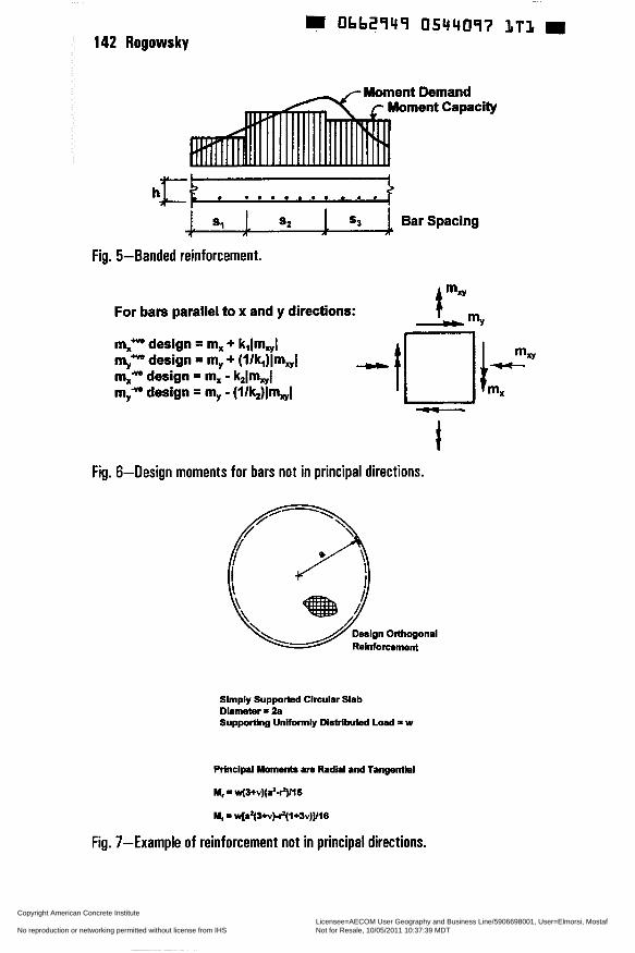
0bb2949 0544097 1 T 1 142 Rogowskv
Moment Demand Moment Capacity
. . i . * . . . . a .
. Sl 1 5 2 5 3 Bar Spacing a n "k
Fig. 5-Banded reinforcement.
For bars parallel to x and y directions:
m," design = m, + kilm,l * design = my + (l/k,)Im,J
design = m, - k,lm,l myy. design = my - (I/k2)lm,l -
t Fig. 6-Design moments for bars not in principal directions.
Slmply Supported Circular Slab Diameter = 2a Supportlng Unifomily Dlstrlbuied Load = w
RTnclpl Momenls am Radial and Tangentlai
M, = w(3+v)(a2$)/16
iu, = w[at(S+v)~(1+3v)]l16
Fig. 7-Example of reinforcement not in principal directions.
Copyright American Concrete Institute Provided by IHS under license with ACI Licensee=AECOM User Geography and Business Line/5906698001, User=Elmorsi, Mostaf
Not for Resale, 10/05/2011 10:37:39 MDTNo reproduction or networking permitted without license from IHS
--`,``,,`,,`,,,,`,``,,,`,`,,,`,-`-`,,`,,`,`,,`---
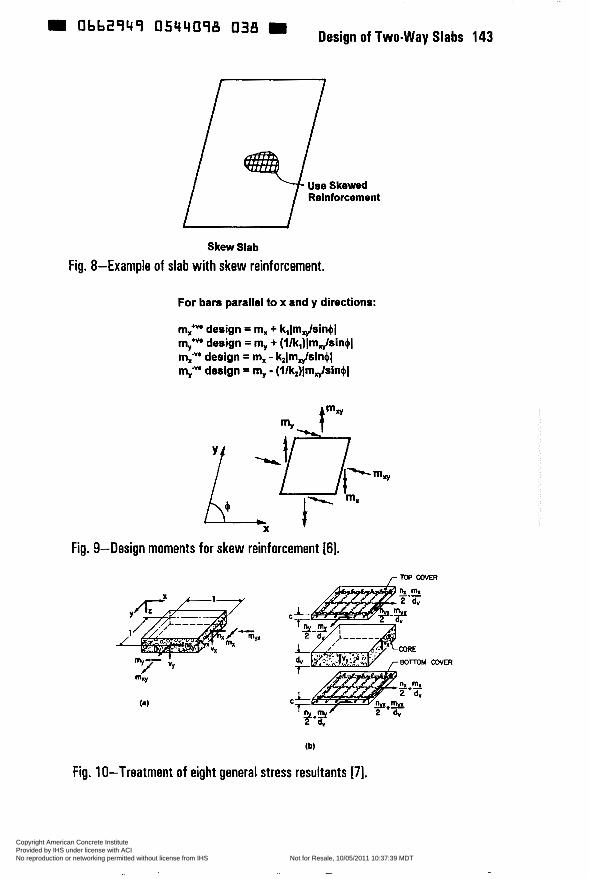
obb2q4q Design of Two-way Slabs 143
Skew Slab
Fig. 8-Example of slab with skew reinforcement.
For bars parallel to x and y directions:
m,* design = m, + krlmJsin,$l my* design = my + (l/k,)lmJsin+1 m,-"' design = m, - k21mJsin,$1 my-"* design = my - (l/kJlmJsin,$l
Fig. 9-Design moments for skew reinforcement [6].
r Top COVER
C
(b)
Fig. 1 O-Treatment of eight general stress resultants [7].
Copyright American Concrete Institute Provided by IHS under license with ACI Licensee=AECOM User Geography and Business Line/5906698001, User=Elmorsi, Mostaf
Not for Resale, 10/05/2011 10:37:39 MDTNo reproduction or networking permitted without license from IHS
--`,``,,`,,`,,,,`,``,,,`,`,,,`,-`-`,,`,,`,`,,`---
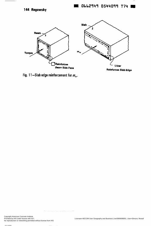
0662749 0544099 T74 144 Rogowsky
Beam Side Face Reinforcea Slab Edge
Fig. 1 1-Slab edge reinforcement for mry.
Copyright American Concrete Institute Provided by IHS under license with ACI Licensee=AECOM User Geography and Business Line/5906698001, User=Elmorsi, Mostaf
Not for Resale, 10/05/2011 10:37:39 MDTNo reproduction or networking permitted without license from IHS
--`,``,,`,,`,,,,`,``,,,`,`,,,`,-`-`,,`,,`,`,,`---
O662949 0544100 51b W
SP 183-9
Design and Construction of Two=Way Slabs for Deflection Control
by A. Scanlon
Synopsis: Deflection control for two-way slab systems requires attention to both design and construction requirements. This paper discusses both aspects and provides a design example to illustrate how construction loads, cracking and time- dependent effects can be accounted for in slab deflection calculations.
Keywords: cracking; deflection control; design; slabs
145 Copyright American Concrete Institute Provided by IHS under license with ACI Licensee=AECOM User Geography and Business Line/5906698001, User=Elmorsi, Mostaf
Not for Resale, 10/05/2011 10:37:39 MDTNo reproduction or networking permitted without license from IHS
--`,``,,`,,`,,,,`,``,,,`,`,,,`,-`-`,,`,,`,`,,`---
146 Scanlon Obb2949 0544bOL 452
AC1 Member Andrew Scanion is a professor of Civil Engineering at The Pennsylvania State University, University Park, PA. He obtained his Ph.D. from the University of Alberta in 1972. He is a former chairman of AC1 Committees 435 (Deflection) and 348 (Safety). His research interests focus on safety and serviceability of structural concrete.
INTRODUCTION
Two-way slab systems have been successfully designed and built in North America for more than 80 years. In most cases, deflection control has been achieved by selecting a slab thickness not less than the code specified minimum thickness given as a fraction of the slab span. Engineers have for the most part used this simple approach and thereby avoided the need to calculate deflections. The code does give the engineer the latitude to select a smaller thickness if deflections are computed and compared with permissible values. Difficulties associated with slab deflection calculations have made this option less than attractive in the past. Even when code minimum thickness is satisfied, serviceabiiity requirements for individual projects may require that deflection calculations be made. Examples include slabs designed to support heavy superimposed dead load and/or live loads such as library stacks or heavy machinery.
Deflection control however is not simply a matter of selecting an adequate thickness. Construction procedures must also be planned and executed in such a manner that the slab wiil not be overloaded during construction and that the concrete will not be loaded before it has achieved a certain strength and stiffness. The AC1 Code addresses this question by specifying that forms shali be removed in such a manner as not to impair safety and serviceabiiity. The 1995 code is more explicit in its treatment of this issue than previous versions of the code.
The objective of this paper is to provide practical guidance to engineers for the realization of serviceable two-way slab systems. Both design and construction are discussed.
DESIGN REQUIREMENTS
Minimum Thickness
Slab systems most susceptible to deflection are fiat plates of uniform thickness and flat slab systems with drop panels. Two-way slab systems with interior beams between columns are inherently stifíer than systems without beams but stiii need to satisfy code provisions for deflection control AC1 3 18 minimum thickness values for slabs without interior beams are given in AC1 3 18 Table 9.5
Copyright American Concrete Institute Provided by IHS under license with ACI Licensee=AECOM User Geography and Business Line/5906698001, User=Elmorsi, Mostaf
Not for Resale, 10/05/2011 10:37:39 MDTNo reproduction or networking permitted without license from IHS
--`,``,,`,,`,,,,`,``,,,`,`,,,`,-`-`,,`,,`,`,,`---
Obb2949 0544302 399 H Design of Two-way Slabs 147
(c) as a fraction of the clear span in the long direction. As noted in the code Commentary these vaiues have evolved through the years based on satisfactory performance. However the Commentary contains a cautionary note implying that these minimum thickness are applicable oniy in situations consistent with “previous experience in loads, environment, materials, boundary conditions, and spans”. Given the complexities of two-way slab behavior it is perhaps surprising that these simple provisions have served designers so well for so long, particularly since no consideration is given to design live load or other factors such as uneven adjacent span lengths and the subjectivity of serviceability requirements.
It is interesting to compare AC1 Code minimum thickness requirements for one-way and two-way slabs. A larger minimum thickness is required for one- way slabs than for two-way flat plates. In addition, the one-way slab minimum thickness applies only to members NOT supporting partitions and other construction likely to be damaged by deflection. This restriction does not apply to two-way construction.
A common criticism of the minimum thickness approach is that the designer does not have any indication of what the actual deflections wiü be. An extensive evaluation of the code minimum thickness equations conducted by Thompson and Scadon (1986) showed that the minimum thickness resulted in calculated deflections that meet the permissible limits of the code over a wide range of design parameters. This study was based on a finite element plate bending analysis accounting for cracking and using AC1 209 (1982) parameters for creep and shrinkage effects. The study allowed for effects of restraint cracking and construction loading and was a rather severe test of the code minimum thickness requirements. The results indicated that live load deflection did not govern for normal apartment and office occupancy load. The critical deflection was incremental deflection for slabs supporting non-structural elements likely to be damaged by large deflections (U480 limit). Based on the results of this study Thompson and Scanlon suggested a 10% increase in minimum thickness for square panels with a linear reduction as a function of aspect ratio. The proposed minimum thickness value matches the current AC1 318 at an aspect ratio of 1.5. The suggested 10% increase has been incorporated in the Canadian Code (1994) although without the reduction as a function of aspect ratio.
DEFLECTION CALCULATIONS
Calculation Methods
Early attempts to calculate slab deflections based onisotropic elastic plate bending theory Timoshenko and Woinowsky-Krieger, (1959) were hampered by the lack of solutions for general cases. AC1 Committee 435 (1974) presented a
Copyright American Concrete Institute Provided by IHS under license with ACI Licensee=AECOM User Geography and Business Line/5906698001, User=Elmorsi, Mostaf
Not for Resale, 10/05/2011 10:37:39 MDTNo reproduction or networking permitted without license from IHS
--`,``,,`,,`,,,,`,``,,,`,`,,,`,-`-`,,`,,`,`,,`---
148 Scanlon 9 Obb2949 0544103 225
summary of available calculation methods including classical solutions, numerical solutions, and methods based on Equivalent Frame or crossing beam analogies. The simplest and most effective approach for design office use is the crossing beam approach as described in a more recent AC1 435 report (1991).
The crossing beam approach is based on the idea that deflections can be calculated for column strips and middle strips based on simple beam deflection equations which are familiar to design engineers (See Fig. 1). Mid-panel deflections can be obtained by adding column strip and middle strip deflections. The bending moments required as input to the deflection equation are obtained as a by-product of the analysis for flexural reinforcement design by the Direct Design Method or Equivalent Frame Method. Since the design moments for flexural design represent approximate elastic solutions, a simple scaling of the moments to the load level of interest is adequate. The method has been shown to produce satisfactory agreement with finite element solutions and also with field-measured deflections.
Loads and Load History
AC1 318 does not specify the loads that are to be considered for deflection calculations other than s p e c M g limits for immediate deflection due to live load and incremental deflection due to sustained load and live load. Long- time deflections of slabs are affected by the level of sustahed load and by the load history during construction. The sustained load depends on the slab dead weight, superimposed dead load, and some fraction of the designlive load. These load components can be calculated with a reasonable degree of confidence. Construction loads however are more difficult to predict at the design stage since the construction procedures are generally not known until after the construction contract has been awarded. Grundy and Kabaila (1963) provided a procedure for estimating constructionloads due to shoring and reshoring when the construction sequence is known. Calculations indicate that such loads may approach or even exceed the design dead plus live load within 28 days of placing the concrete. This early age loading affects long-time deflections by causing cracking that reduces the slab stiffness for future loading and by causing early age creep deformation that may not be completely recoverable on removal of the construction loads. AC1 435 (1991) suggests that if the construction procedure is unknown, a load of 2 x dead load be used to estimate the short-time deflection due to construction load. This may exceed the design dead plus live load but will provide an allowance for unanticipated overload conditions that would affect the cracking and deflection of the slab. A more accurate estimate of peak construction load may be made if the construction shoring and re-shoring procedure is known. Another source of potentially high loading on slabs during construction is storage of materials on the slab due to lack of storage space at the construction site.
The 1995 AC1 Code provides more explicit requirements for construction
Copyright American Concrete Institute Provided by IHS under license with ACI Licensee=AECOM User Geography and Business Line/5906698001, User=Elmorsi, Mostaf
Not for Resale, 10/05/2011 10:37:39 MDTNo reproduction or networking permitted without license from IHS
--`,``,,`,,`,,,,`,``,,,`,`,,,`,-`-`,,`,,`,`,,`---
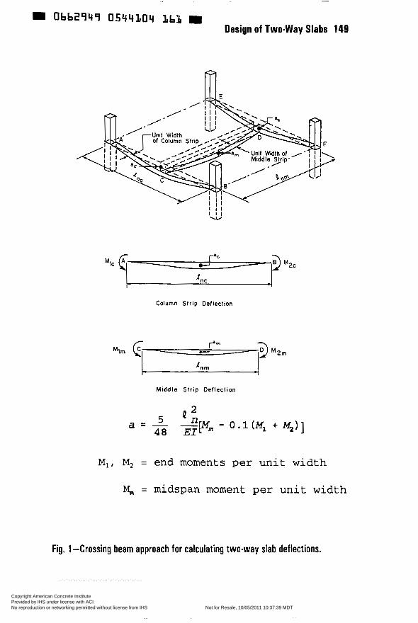
ObbL1944 0544304 lib3 9 Design of Two-way Slabs 149
I I I XW
Column Strip Deflection
Middle Str ip Deflection
MI, M, = end moments per unit width
M,,, = midspan moment per unit width
Fig. 1 -Crossing beam approach for calculating two-way slab deflections.
Copyright American Concrete Institute Provided by IHS under license with ACI Licensee=AECOM User Geography and Business Line/5906698001, User=Elmorsi, Mostaf
Not for Resale, 10/05/2011 10:37:39 MDTNo reproduction or networking permitted without license from IHS
--`,``,,`,,`,,,,`,``,,,`,`,,,`,-`-`,,`,,`,`,,`---
Obb2949 0544305 OTö W 150 Scanlon
procedures than previous versions of the code. The contractor is required to develop a procedure and schedule for removal of shores and installation of reshores. Information from such a pian can be used to evaluate potential problems due to construction loads before construction starts. Special measures are required if construction loads are expected to exceed the specified superimposed dead load and live load.
Cracking
Studies have shown that slab deflections are sensitive to the extent of cracking because slab sections are generally lightly reinforced, sometimes requiring only minimurn reinforcement for flexural strength. The cracked transformed moment of inertia is considerably smaller than the gross moment of inertia leading to a signjfícant loss of stiffness if cracking occurs. It is essential therefore to take proper account of cracking in slab deflection calculations.
Figure 2 shows plots of moment vs curvature for three reinforcement ratios. In each case the linear relationship through the origin is based on the cracked transformed section moment of inertia and represents a lower bound on the section st3ks.s. The other relationship plotted is based on gross moment of inertia up to cracking and the effective moment of inertia after cracking. Ais0 shown for each case are the yield moment and the range of service load moments. For a reinforcement ratio of 0.0075 the effective moment of inertia provides a stiffness close to that corresponding to the cracked transformed section. For a reinforcement ratio of 0.0019 (close to minimum steel) the service load moment range is below the calculated value of M, and there is a large difference between the cracked and uncracked stiffriess. Any effect leading to a reduction in the moment required to cause cracking could have a signincant effect on flexural stiffness. The reinforcement ratio of 0.0038 provides a difference between cracked and uncracked stiffness that is between the other two cases. Using Monte Carlo simulation, Ramsay et al. (1979) have shown that the variability of immediate deflections increases signiñcantly when the applied moment is close to the cracking moment.
Moments due to applied load and development of tensile stress due to temperature and shrinkage restraint are the two principal sources of cracking in slab systems. Cracking occurs when the applied moment exceeds the cracking moment calculated on the basis of the concrete modulus of rupture. In column- supported slab systems intensities of negative moment increase rapidly in the vicinity of the columns. Cracking is likely to occur at relatively low load levels causing a redistribution of moments approaching the approximate distributions used for design of reinforcement in column and middle strips. Ifin-plane restraint to temperature and shrinkage occurs tensile stresses build up that can reduce the magnitude of applied moment required to cause cracking. In some cases shrinkage restraint stresses may be sufficient to cause cracking before moments
Copyright American Concrete Institute Provided by IHS under license with ACI Licensee=AECOM User Geography and Business Line/5906698001, User=Elmorsi, Mostaf
Not for Resale, 10/05/2011 10:37:39 MDTNo reproduction or networking permitted without license from IHS
--`,``,,`,,`,,,,`,``,,,`,`,,,`,-`-`,,`,,`,`,,`---
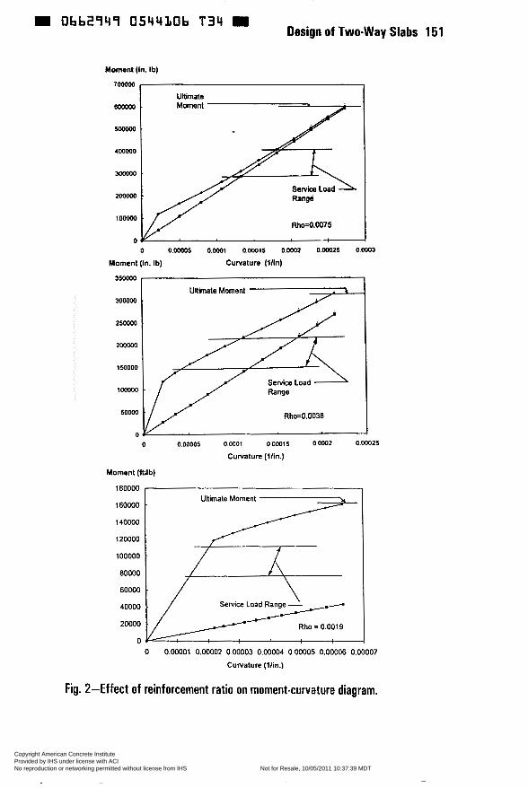
Design of Two-way Slabs 151 0bb2949 054430b T 3 4
Moment (in. Ib)
700000
U h a t e 600000
4 m
300000
200000
1 o m
O O O.oWO5 O.oW! 0.00015 O.OW2 0.00025 0.0003
Moment (in. Ib) Curvature (ilin)
35oooo , 3 0 0 0
25oooo
20woo
IMOW
100000
SWW
O O o.ooaos ow01 o00015 0.0002 0.00025
Curvature (Vin.)
Moment (&,lb)
180000 , Ultimate Marnent
160000 .
140000
120000
60000 8oooo I * 40000
Rho = 0.001 9
O O 0.00001 0.00002 O00003 0.00004 0.00005 0.00006 0.00007
Curvature (llin.)
Fig. 2-Effect of reinforcement ratio on moment-curvature diagram.
Copyright American Concrete Institute Provided by IHS under license with ACI Licensee=AECOM User Geography and Business Line/5906698001, User=Elmorsi, Mostaf
Not for Resale, 10/05/2011 10:37:39 MDTNo reproduction or networking permitted without license from IHS
--`,``,,`,,`,,,,`,``,,,`,`,,,`,-`-`,,`,,`,`,,`---
W Obb2949 0544107 970 m 152 Scanlon
are applied. These effects are difficult to q u a n w but can be accounted for in an approximate fashion by calculating the cracking moment on the basis of a reduced modulus of rupture as suggested by Scanlon and Murray (1982).
Other arguments can be made for reducing the modulus of rupture used in deflection calculations Laboratory data on modulus of rupture are based on small carefully made specimens tested in a manner to minimize boundary restraints. Slab systems are constructed over large plan areas often under less than perfect conditions of workmanship and weather. Much higher variability can therefore be expected for in-situ tensile strength than for tensile strength of laboratory specimens. Also, if construction loads are controlled to minimize cracking under construction loading, stresses in the slab may be close to the tensile strength under sustained loads. Although there is little data on tensile strength under sustained load, it would be reasonable to expect a reduction as is the case for compressive strength under sustained load.
Scanlon and Murray (1982) suggested a value of 4 E for use in design calculations for slab deflections. This approach has been found to give reasonable correlation with field-measured deflections by Jokinen and Scanlon (1987), Graham and Scanlon (1986), and Montgomery et. al. (1988).
Creep and Shrinkage
Time-dependent deflections occur due to creep under sustained stress and warping due to shrinkage on unsymmetrically reinforced sections. Methods to account for these effects separately are given by AC1 209 (1982) and applied to slab deflections by AC1 435 (1991). However AC1 318 allows time-dependent deflections to be computed based on a single long-time multiplier. A number of researchers have suggested that the basic multiplier of 2 should be increased for slab deflections (AC1 435, 1991). In some cases proposals for significant increases in the long-time multiplier have been based on field-measured deflections. However it is not clear whether the additional deflections are related to creep and shrinkage alone or to the combined effects of cracking, creep, and shrinkage particularly as affected by quality control during construction.
Creep and shrinkage in slabs may be somewhat higher than in beams due to higher surface to volume ratio leading to more rapid loss of moisture. For uncracked slabs, shrinkage warping may be a higher percentage of total deflection than is the case for cracked slabs, but experience has shown that slab deflections are not usually a problem if the slab remains uncracked. Slabs loaded at early age due to shoring and reshoring can experience irrecoverable creep during the construction stage. Graham and Scanlon (1986) suggested that with a reduced effective modulus of rupture to account for cracking an increase in the multiplier from 2 to 2.5 would account for shrinkage warping effects and non-
Copyright American Concrete Institute Provided by IHS under license with ACI Licensee=AECOM User Geography and Business Line/5906698001, User=Elmorsi, Mostaf
Not for Resale, 10/05/2011 10:37:39 MDTNo reproduction or networking permitted without license from IHS
--`,``,,`,,`,,,,`,``,,,`,`,,,`,-`-`,,`,,`,`,,`---
Design of Two-way Slabs 153 Obb2949 0544308 807 9
recoverable creep due to construction loads. These recommendations were based on average creep properties. AC1 435 (1991) provides suggestions for adjusting the multiplier if higher (or lower) than normal creep and shrinkage characteristics are expected.
PERMISSIBLE DEFLECTIONS
Maximum permissible computed deflections are given in AC1 3 18 Table 9.5 (b). Different limits are specified depending on whether or not the slab supports nonstructural elements likely to be damaged by large deflections. The code does not spec@ anexplicit limit on total deflection, however the limits on incremental deflection indirectly Illnit total deflection. Since the code provides minimum requirements for design, more stringent limits may need to be considered for specific applications.
Maximum permissible computed deflections are specified as a fraction of span length, 1. In two-way slab systems the span to be used depends on which deflection component is being considered. For checking column and middle strip deflections the corresponding span for each column and middle strip should be used. Because moment intensities are higher in the column strips, the column strip deflection in the long span direction wiü usually govern. Also, because partitions are most often placed along column lines, the column strip deflection will normaliy be most critical with respect to damage to non-structural elements. The maximum total deflection, calculated as the sum of orthogonal column and middle strip deflections, will occur at mid-panel. In this case the span should be measured along the diagonal of the panel to calculate the deflection limit.
It is worth emphasizing that limits are placed on computed deflections rather than field-measured deflections. The calculation criteria provided in the code are intended to provide an estimate of the average deflection that would be expected under prescribed loading conditions. However because of uncertainties associated with material properties and structural modeling as well as loading it is to be expected that in some cases deflections measured in the field wiü exceed the calculated values, Since the limits given in the AC1 Code appear to have resulted in satisfactory performance over the years, these limits must have a reasonable amount of conservativism built into them, in terms of providing serviceable structures.
CONSTRUCTION PROCEDURES
Deflection control of multi-story slab systems is affected by the construction methods used. Shoring and re-shoring procedures influence the magnitude of loads on the slab during the construction phase when the concrete is at early age. The 1995 AC1 Code provides more explicit requirements than previous versions of the code. The contractor is required to develop a procedure and schedule for
Copyright American Concrete Institute Provided by IHS under license with ACI Licensee=AECOM User Geography and Business Line/5906698001, User=Elmorsi, Mostaf
Not for Resale, 10/05/2011 10:37:39 MDTNo reproduction or networking permitted without license from IHS
--`,``,,`,,`,,,,`,``,,,`,`,,,`,-`-`,,`,,`,`,,`---
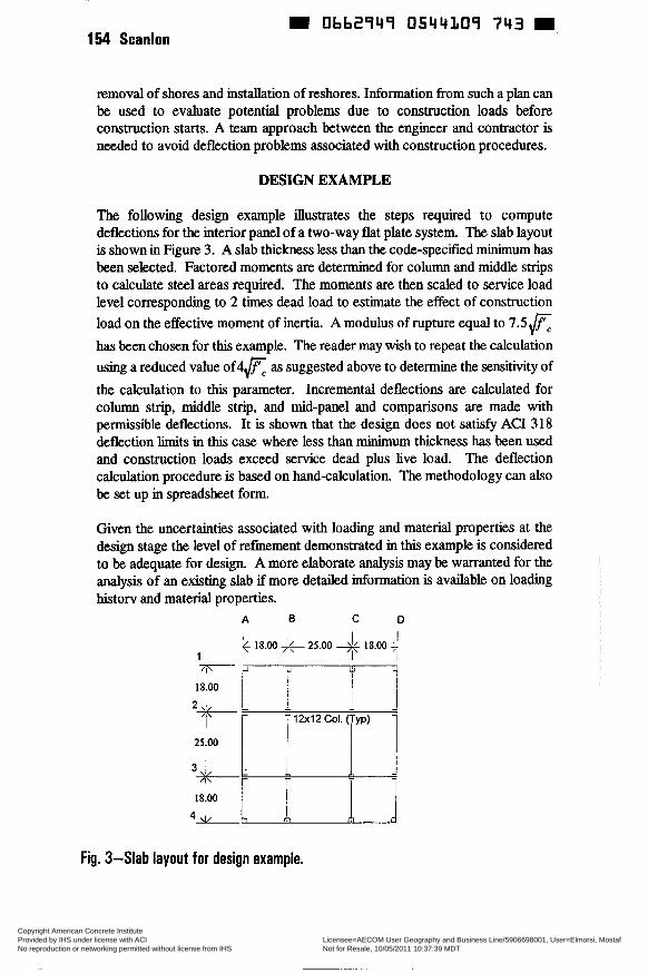
0662949 0544109 743 154 Scanlon
removal of shores and installation of reshores. Information from such a plan can be used to evaluate potential problems due to construction loads before construction starts. A team approach between the engineer and contractor is needed to avoid deflection problems associated with construction procedures.
DESIGN EXAMPLE
The following design example illustrates the steps required to compute deflections for the interior panel of a two-way flat plate system. The slab layout is shown in Figure 3. A slab thickness less than the code-specified minimum has been selected. Factored moments are determined for column and middle strips to calculate steel areas required. The moments are then scaled to service load level corresponding to 2 times dead load to estimate the effect of construction load on the effective moment of inertia. A modulus of rupture equal to 7.5E has been chosen for this example. The reader may wish to repeat the calculation using a reduced value o f 4 E as suggested above to determine the sensiíivity of the calculation to this parameter. Incremental deflections are calculated for column strip, middle strip, and mid-panel and comparisons are made with permissible deflections. It is shown that the design does not satisfy AC1 318 deflection limits in this case where less than minimum thickness has been used and construction loads exceed service dead plus live load. The deflection calculation procedure is based on hand-calculation, The methodology can also be set up in spreadsheet form.
Given the uncertainties associated with loading and materiai properties at the design stage the level of refinement demonstrated in this example is considered to be adequate for design. A more elaborate analysis may be warranted for the analysis of an existing slab if more detailed information is available on loading historv and material properties.
A B C D l I I f 18.00 - 25.00 ++ 18.00 +
1 I 'I
ia'oo i T
Fig. 3-Slab layout for design example.
Copyright American Concrete Institute Provided by IHS under license with ACI Licensee=AECOM User Geography and Business Line/5906698001, User=Elmorsi, Mostaf
Not for Resale, 10/05/2011 10:37:39 MDTNo reproduction or networking permitted without license from IHS
--`,``,,`,,`,,,,`,``,,,`,`,,,`,-`-`,,`,,`,`,,`---
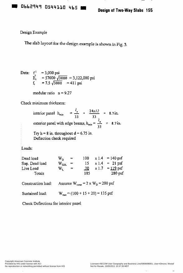
abb2q4q 05Li4LL0 4bs 9 Design of Two-way Slabs 155
Design Example
The slab layout for the design example is shown in Fig. 3.
Data: f: =3,OOOpsi E, = 57000 = 3,122,000 psi f, =7.5 =411 psi
modular ratio n = 9.27
Check minimum thickness:
‘n exterior panel with edge beams, kin = - = 8.7in.
Try h = 8 in. throughout d = 6.75 in. Deflection check required
33
Loads:
Dead load W, = 100 x 1.4 =140psf 15 x 1.4 = 21 psf
Live Load W, = 2 ~ 1 . 7 = u p s f Totals 185 280 psf
Sup. Dead load WSDL =
Construction load: Assume W,,,, = 2 x W, = 200 psf
Sustained load: W,,, = (100 + 15 + 20) = 135 psf
Check Deflections for interior panel
Copyright American Concrete Institute Provided by IHS under license with ACI Licensee=AECOM User Geography and Business Line/5906698001, User=Elmorsi, Mostaf
Not for Resale, 10/05/2011 10:37:39 MDTNo reproduction or networking permitted without license from IHS
--`,``,,`,,`,,,,`,``,,,`,`,,,`,-`-`,,`,,`,`,,`---
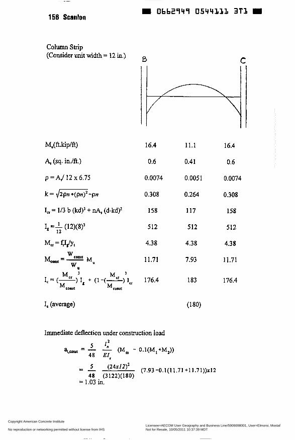
~
156 Scanlon
Column strip (Consider unit width = 12 in.)
M,(fr.kip/ft)
A, (sq. in./ft.)
p = A/ 12 x 6.75
I,, = 113 b (kd)? + nA, (d-kd)?
I, =+ (12)(8)?
MCr = fJgfYl
I, (average)
i3 C
16.4
0.6
0.0074
0.308
158
512
4.38
1 1.71
176.4
Immediate deflection under construction load 2
5 4 ai.cont, = - - (M, - 0.1(MI+M2))
48 Ei,
11.1
0.41
0.005 1
0.264
117
512
4.38
7.93
183
(1 80)
16.4
0.6
0.0074
0.308
158
512
4.38
11.71
176.4
- - - (24x12)2 (7.93-0.1(11.71+11.71))~12 48 (3122)(180)
= 1.03 in.
Copyright American Concrete Institute Provided by IHS under license with ACI Licensee=AECOM User Geography and Business Line/5906698001, User=Elmorsi, Mostaf
Not for Resale, 10/05/2011 10:37:39 MDTNo reproduction or networking permitted without license from IHS
--`,``,,`,,`,,,,`,``,,,`,`,,,`,-`-`,,`,,`,`,,`---

0544LL2 238 Design of Two-way Slabs 157
Immediate deflection due to sustained load
135 200
& = - (1.03) = 0.695h.
Immediate deflection due to non-sustained live load,
a, == x 1.03 h. ~ 0 . 2 6 h.
Incremental deflection
a, = 2 ~ 0 . 6 9 5 + 0.26 = 1.65 in.
Permissible computed deflection
24x12 = 0.60in. € 1.65 in. 41, - - - - NG - ‘n - 480 480
Mu (ft.kip/ft)
A, (sq. in./ft.)
p = (12 x 6.75)
k
I c r
4 M c r
M,,,
IC
IC (average)
5.5 7.4 5.5
0.20 0.27 0.20
0.0025 0.0033 0.0025
0.193 0.218 0.193
64 83 63
512 512 512
4.38 4.38 4.38
3.93 5.29 3.93
512 323 512
(41 8)
Copyright American Concrete Institute Provided by IHS under license with ACI Licensee=AECOM User Geography and Business Line/5906698001, User=Elmorsi, Mostaf
Not for Resale, 10/05/2011 10:37:39 MDTNo reproduction or networking permitted without license from IHS
--`,``,,`,,`,,,,`,``,,,`,`,,,`,-`-`,,`,,`,`,,`---

158 Scanlon 0662949 0544333 174
- 5 ( 2 4 ~ 1 2 ) ~ a,.conrt - - (5.29 - 0.1(3.93 +3.93))x12
48 (3 122)(4 18)
= 0.36 in.
13' x 0.36 = 0.24h. ai,, - - 200
-
a, = - 'o x 0.36 = 0.09 200
a,, = 2x0.24i-O.09 = 0.57 in.
Mid Panel Deflection
a,, = 1.65 f 0.57 = 2.22 in.
Span length dong diagonal = d-' = 33.94 ft.
- 33'94x12 = 0.85 < 2.22 in. %i = - - NG 480 480
Comments
Incremental deflections for column strip and mid-panel do not meet AC1 318 requirements. Note that thickness is less than minimum thickness and assumed construction loads are higher than total service load. Restraint cracking has not been considered.
In this example, the maximum load has been assumed to occur during construction early in the life of the slab. It is therefore appropriate to base I, on this load level for the life of the structure since the slab does not becorne uncracked after cracking occurs.
Copyright American Concrete Institute Provided by IHS under license with ACI Licensee=AECOM User Geography and Business Line/5906698001, User=Elmorsi, Mostaf
Not for Resale, 10/05/2011 10:37:39 MDTNo reproduction or networking permitted without license from IHS
--`,``,,`,,`,,,,`,``,,,`,`,,,`,-`-`,,`,,`,`,,`---
CONCLUSION
This paper has outlined factors that have a signiIicant effect on slab serviceability related to deflection control. Both minimum thickness and deflection calculation have been discussed as means to achieve control of deflections in design. Appropriate construction procedures are also necessary for serviceable slabs. Although relatively straightforward approaches to the calculation of deflections have been provided this should not be construed as encouragement to use slab thicknesses less than the code-specified minimum values. Experience has shown that slabs that develop deflection problems are usualiy those that have less than minimum thickness often combined with problems during construction. Problems have also developed in slabs constructed with concretes having high creep and shrinkage characteristics. Slabs with special serviceability requirements may require larger than minimum thickness.
REFERENCES
AC1 Committee 209 (1982). Prediction of Creep, Shrinkage, and Temperature Effects. American Concrete Institute.
AC1 Committee 318 (1995). Building Code Requirements for Structural Concrete. American Concrete Institute, Detroit.
AC1 Committee 435 (1974). Deflection of Two-way Reinforced Concrete Floor Systems, American Concrete Institute, Detroit.
AC1 Committee 435 (1991). State-of-the-Art Report : ControlofTwo-Way Slab Deflections. American Concrete Institute, Detroit.
Canadian Standards Association Committee A23.3 (1994). Design of Concrete Structures. Canadian Standards Association, Rexdale, Ontario, 220 pp.
Jokinen, E.P. and Scanlon, A. (1987). Field-Measured Two-way Slab Deflections. Canadian Journal of Civil Engineering, V. 14, No. 6, pp. 807-819.
Graham, C.J. and Scanlon, A. (1986). Long-The Multipliers for Estimating Two-way Slab Deflections. AC1 Journal, V. 83, No. 6, pp. 899-908.
Grundy, P. and Kabaila, P. (1963). Construction Loads on Slabs with Shored Formwork in Multi-Story Buildings. AC1 Journal, V. 60, No. 12, pp. 1729- 1738.
Montgomery, C.J., Brockbank, R.G., Stephens, M.J., and Krywiak, G. (1988). Design, Construction, and Deflection of Two-way Slabs. Proceedings of Symposium on Serviceability of Buildings, University of Ottawa, pp. 112-123.
Copyright American Concrete Institute Provided by IHS under license with ACI Licensee=AECOM User Geography and Business Line/5906698001, User=Elmorsi, Mostaf
Not for Resale, 10/05/2011 10:37:39 MDTNo reproduction or networking permitted without license from IHS
--`,``,,`,,`,,,,`,``,,,`,`,,,`,-`-`,,`,,`,`,,`---
160 Scanlon
~
Obb2949 0544315 T 4 7
Ramsay, R.J., Mirza, S.A., and MacGregor, J.G. (1979). Monte Carlo Study of Short Time Deflections of Reinforced Concrete Beams. AC1 Journal, V. 76, No. 8, pp. 897-918.
Scanlon, A. and Murray, D.W. (1982). Practical Calculation of Two-way Slab Deflections. Concrete International, V. 4, No. 11, pp. 43-50.
Thompson, D.P. and Scanlon, A. (1986). Minimum Thickness Requirements for Control of Two-way Slab Deflections. AC1 Structural Journal, V. 85, No. 1, pp. 12-22.
Tmoshenko, S . and Woinowsky-Krieger, S. (1959). Theory of Plates and Shells. McGraw-Hill Book Co., New York, 580 pp.
Copyright American Concrete Institute Provided by IHS under license with ACI Licensee=AECOM User Geography and Business Line/5906698001, User=Elmorsi, Mostaf
Not for Resale, 10/05/2011 10:37:39 MDTNo reproduction or networking permitted without license from IHS
--`,``,,`,,`,,,,`,``,,,`,`,,,`,-`-`,,`,,`,`,,`---
ûbb2949 05Y4LLb 983 m
SP 183-10
Strip Design for Punching Shear
by S. Alexander
Synopsis: Apart from column-slab connections, almost all reinforced concrete connections can be analyzed and designed using plastic strut and tie models. The strut and tie model provides a simple, rational and highly transparent explanation for the flow of forces within a connection. By examining a unique substructure within a column-slab connection, Alexander and Simmonds (1) develop what amounts to a plastic strut and tie model for concentrically loaded connections between interior columns and two-way slabs with orthogonal reinforcement. On the basis of this model, a general design procedure for gravity-loaded column-slab connections has been developed. The resulting design procedure is simple and it handles column-slab connection problems that are not easily analyzed by existing code provisions. This paper outlines the design procedure and the important features of the model upon which it is based. The model is compared both to existing test results in the literature and to the AC1 code design procedure. Two design examples are included.
Keywords: columns; punching shear; reinforced concrete; slabs
161 Copyright American Concrete Institute Provided by IHS under license with ACI Licensee=AECOM User Geography and Business Line/5906698001, User=Elmorsi, Mostaf
Not for Resale, 10/05/2011 10:37:39 MDTNo reproduction or networking permitted without license from IHS
--`,``,,`,,`,,,,`,``,,,`,`,,,`,-`-`,,`,,`,`,,`---
162 Alexander
Scott Alexander is an Associate Professor of Civil and Environmental Engineering at the University of Alberta. His research interests are in the design and behavior of two-way flexural systems, the structural application of high-strength concrete, and the assessment and rehabilitation of existing structures. He is a member of AC1 committees 363-High Strength Concrete, and 42 1-Design of Reinforced Concrete Slabs.
INTRODUCTION
For both analysis and design, it is useful to subdivide a reinforced concrete member into B-regions and D-regions. B-regions are those portions of the member that behave as a slender beam. D-regions are adjacent to discontinuities or disturbances in either the loading or the geometry of the member. D-regions behave like deep beams.
The distinguishing characteristic of a B- or D-region is the predominant mechanism of moment gradient or shear transfer. In a slender beam, moment gradient is caused by a varying flexural tension force acting on a more or less constant moment arm. Such behavior is called beam action. In a deep beam, moment gradient results from a constant tensile force acting on a varying moment arm. This behavior is called arching action.
it is both convenient and theoretically sound to model beam action shear transfer in terms of an average shear stress acting on the cross-section. As a result, a reasonable design strategy for slender members is to limit the average shear stress to some critical value. However, an average shear stress is not sufficient to model the behavior in a D-region. D-regions are best described using strut-and-tie models.
Column-slab connections exhibit the characteristics of both B and D-regions. Tests show that radial arching action is an important mechanism of shear transfer between a slab and a column, suggesting that column-slab connections should be considered D-regions. In the circumferential direction, however, column-slab connections behave more like B-regions. Measurements show that the distribution of circumferential strain is linear through the thickness of the slab, with maximum compression at the slab soffit.
SHEAR TRANSFER MECHANISM
Alexander and Simmonds (1) present a model, called the bond model, for the transfer of shear between columns and slabs with bonded orthogonal reinforcement. According to the bond model, an interior column-slab connection may be modeled with four slab strips, called radial strips, extending from the
Copyright American Concrete Institute Provided by IHS under license with ACI Licensee=AECOM User Geography and Business Line/5906698001, User=Elmorsi, Mostaf
Not for Resale, 10/05/2011 10:37:39 MDTNo reproduction or networking permitted without license from IHS
--`,``,,`,,`,,,,`,``,,,`,`,,,`,-`-`,,`,,`,`,,`---
Design of Two-way Slabs 163 - Obb2949 0544338 75b M
column parallel to the slab reinforcement to a point of zero shear, as shown in Figure 1 . The radial strips divide the slab into four quadrants. No load can reach the column without passing through one of the radial strips. Each radial strip is loaded on its side faces by the adjacent quadrants of two-way slab.
Figure 2 shows a free body diagram of one-half of a radial strip. The strip is loaded on its side face by a combination of plate bending moments, m,,, torsional moments, m,, and shears, Y. The strip is supported by a vertical reaction, P, at the column supported end and bending moments, Mms and MF, at the column and remote ends of the strip, respectively.
The net internal vertical shear at any point along the side face of a radial strip depends upon the interaction of bending and torsional moment gradient at that point. A number of assumptions are made about the nature of this internal shear. First, the mechanisms generating the net shear are assumed to be consistent with those of a slender flexural member. Second, it is assumed that there is an upper limit on the net internal shear. Finally, the mechanisms generating this shear are assumed to be ductile enough to allow for the optimal redistribution of the net internal shear. This results in the simplified free body diagram of a radial strip at ultimate load, shown in Figure 3. The loading term, w, is the limiting net internal shear that can be carried by the slab. Because the radial strip is loaded on two faces, the total distributed line load on the strip is 2w.
The flexural strength of the radial strip, M,, is the sum of the negative and positive flexural capacities, M& and M,,, at the ends of the strip. The loaded length of the strip is 1 and total load carried by one strip is P,. Equilibrium of the radial strip requires that:
The loaded length of each radial strip behaves like a deep beam under a uniform load - a D-region in which shear is carried to the column by means of arching action. In contrast, the quadrants of two-way slab are B-regions, each delivering an internal shear to the side faces of the supporting radial strip.
The shear capacity of a strip is limited by the intensity of the internal shear that can be carried on the boundary between the strip and its adjacent quadrants of slab and the flexural capacity of the strip itself. Since the slab behaves as a slender flexural member in the direction perpendicular to a radial strip, an appropriate limiting value for the internal shear between the strips and the quadrants of slab is the design value for one-way shear strength, w, of the slab. Based on AC1 3 18-95 (2), w is given by:
i31 w = (75 x d x 0 . 1 7 E
Copyright American Concrete Institute Provided by IHS under license with ACI Licensee=AECOM User Geography and Business Line/5906698001, User=Elmorsi, Mostaf
Not for Resale, 10/05/2011 10:37:39 MDTNo reproduction or networking permitted without license from IHS
--`,``,,`,,`,,,,`,``,,,`,`,,,`,-`-`,,`,,`,`,,`---
= Obb2949 0544119 692 164 Alexander
where #is the reduction factor for shear, d i s the flexural depth of the slab and f,' is the specified concrete strength measured in MPa.
The flexural capacity of a strip, M,, may be obtained in one of two ways. If the distribution of reinforcement is known, then the flexural capacities , Mneg and MPs, at the ends of the sirip are given by:
Pw fu [4a1 Mneg = 4 xpnegxh x ~8 x (1 - 3) xpmg x x 0 . 9 ~ 8
[4b] where 4 is the reduction factor for flexure,& is the yield stress of the reinforcement, c is the column dimension perpendicular to the strip, and pneg and pps are the ratios of top and bottom reinforcement respectively. Alternatively, the values of M& and MPaF may be determined directly from the design moments. The latter approach is more useful in design and will be examined in greater detail later.
Mpos = 4 x ppos xfy x c 8 x (1 - %) = 4 x ppos xfu x 0 . 9 ~ 8
A COMPARISON BETWEEN THE STRIP MODEL FOR SHEAR AND THE AC1 CODE
In the literature, there is a large body of test results of slab-column connections under concentric load. A database of 145 separate tests fiom ten different sources (3 to 12) is used to evaluate both the proposed model and the AC1 code model (2). All test specimens had either square or circular columns and uniformly spaced flexural reinforcement. Tests reported in references 3 through 8 and 12 are of isolated slab-column connections with no rotational restraint on the slab boundary. References 9 to 11 report tests with continuous slab boundaries. Reference 12 features connections with high-strength concrete.
Setting all + factors equal to 1 .O, failure loads for all 145 tests were predicted using Equations 2,3, and 4. On average, the strip model is conservative, with an average ratio of test to predicted load of 1.3 and a coefficient of variation of 12.2%. For comparison, similar predictions were made using the procedure in AC1 3 18-89. In this case, the average ratio of test to predicted load is 1.56 with a coefficient of variation of 26.2%.
Figures 4 and 5 graph the results obtained with both the strip model and the AC1 code method against slab reinforcing ratio and concrete strength. As shown in Figures 4a and 5a, the strip model produces uniformly accurate results over a wide range of reinforcing ratios and concrete strengths. In contrast, Figure 4b shows that predictions using the AC1 method become more conservative and more scattered with increasing reinforcing ratio. Figure 5b suggests that the AC1 procedure may be less conservative with increasing concrete strength.
Figures 4 and 5 show clearly that the strip model is a more reliable and accurate predictor of punching failure than the code model. One might suspect
Copyright American Concrete Institute Provided by IHS under license with ACI Licensee=AECOM User Geography and Business Line/5906698001, User=Elmorsi, Mostaf
Not for Resale, 10/05/2011 10:37:39 MDTNo reproduction or networking permitted without license from IHS
--`,``,,`,,`,,,,`,``,,,`,`,,,`,-`-`,,`,,`,`,,`---
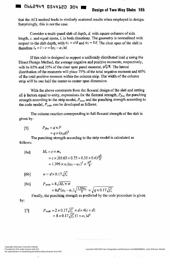
0544120 304 Design of Two-way Slabs 165
that the AC1 method leads to similarly scattered results when employed in design. Surprisingly, this is not the case.
Consider a multi-panel slab of depth, d, with square columns of side length, c, and equal spans, 1, in both directions. The geometry is normalized with respect to the slab depth, with a1 = dd and (12 = l/d. The clear span of the slab is therefore 1, = 1 - c = (a2 - a I )d.
If this slab is designed to support a uniformly distributed load q using the Direct Design Method, the average negative and positive moments, respectively, will be 65% and 35% of the clear span panel moment, ql?S. The lateral distribution of the moments will place 75% of the total negative moment and 60% of the total positive moment within the column strip. The width of the column strip will be one half the center-to-center span dimension.
With the above constraints from the flexural design of the slab and setting all I$ factors equal to unity, expressions for the flexural strength, PJex, the punching strength according to the strip model, PFlriP, and the punching strength according to the code model, Pcode, can be developed as follows.
The column reaction corresponding to full flexural strength of the slab is given by:
PJex = q x 12 2
FI = q x (a24
The punching strength according to the strip model is calculated as follows:
M, = c x m s [bal = c x 2(0.65 x 0.75 + 0.35 x 0.6)$
2 qd’ =1.395xa,(a2-ai) x s
Finally, the punching strength as predicted by the code procedure is given by:
[71 PCde=2x0.17& xdx4(c+d) = 8 X 0 . 1 7 z ( 1 +ai)&
Copyright American Concrete Institute Provided by IHS under license with ACI Licensee=AECOM User Geography and Business Line/5906698001, User=Elmorsi, Mostaf
Not for Resale, 10/05/2011 10:37:39 MDTNo reproduction or networking permitted without license from IHS
--`,``,,`,,`,,,,`,``,,,`,`,,,`,-`-`,,`,,`,`,,`---
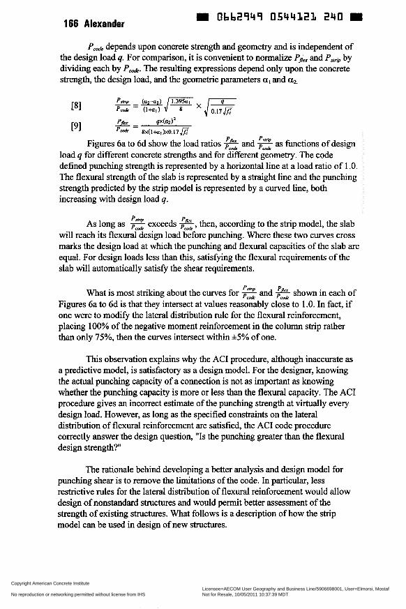
166 Alexander Obb2949 05441i21 240
depends upon concrete strength and geometry and is independent of the design load 4. For comparison, it is convenient to normalize Pia and PSlnp by dividing each by Ped. The resulting expressions depend only upon the concrete strength, the design load, and the geometric parameters al and a2.
pfir - qx(ad2 [91 pd 8x~ l+a l~xo . l7 f i
Figures 6a to 6d show the load ratios % and 2 as functions of design load q for different concrete strengths and for different geometry. The code defined punching strength is represented by a horizontal line at a load ratio of 1 .O. The flexural strength of the slab is represented by a straight line and the punching strength predicted by the strip model is represented by a curved line, both increasing with design load q.
As long as 2 exceeds 2, then, according to the strip model, the slab will reach its flexural design load before punching. Where these two curves cross marks the design load at which the punching and flexural capacities of the slab are equal. For design loads less than this, satisfiing the flexural requirements of the slab will automatically satis@ the shear requirements.
What is most striking about the curves for 2 and & shown in each of Figures 6a to 6d is that they intersect at values reasonably close to 1 .O. In fact, if one were to modi@ the lateral distribution rule for the flexural reinforcement, placing 100% of the negative moment reinforcement in the column strip rather than only 75%, then the curves intersect within %5% of one.
This observation explains why the AC1 procedure, although inaccurate as a predictive model, is satisfactory as a design model. For the designer, knowing the actual punching capacity of a connection is not as important as knowing whether the punching capacity is more or less than the flexural capacity. The AC1 procedure gives an incorrect estimate of the punching strength at virtually every design load. However, as long as the specified constraints on the lateral distribution of flexural reinforcement are satisfied, the AC1 code procedure correctly answer the design question, "Is the punching greater than the flexural design strength?"
The rationale behind developing a better analysis and design model for punching shear is to remove the limitations of the code. In particular, less restrictive rules for the lateral distribution of flexural reinforcement would allow design of nonstandard structures and would permit better assessment of the strength of existing structures. What follows is a description of how the strip model can be used in design of new structures.
Copyright American Concrete Institute Provided by IHS under license with ACI Licensee=AECOM User Geography and Business Line/5906698001, User=Elmorsi, Mostaf
Not for Resale, 10/05/2011 10:37:39 MDTNo reproduction or networking permitted without license from IHS
--`,``,,`,,`,,,,`,``,,,`,`,,,`,-`-`,,`,,`,`,,`---

Design of Two-way Slabs 167 - 0662749 0544322 LB7
DESIGN MODEL
The North American approach to the design of two-way column supported slabs is to address the shear and flexural requirements of the slab separately. A layout of reinforcement is selected to satis@ flexural equilibrium. The shear strength of the slab-column connections is checked by means of a calculation that is independent of the flexural design.
A similar approach can be taken using the strip method for shear. For a given connection geometry and distribution of flexural reinforcement, the strip method can be used to calculate a punching capacity. However, while valuable for the assessment of existing structures, this is not the best approach for design.
The strip method for shear highlights the link between shear and flexural design. It is, in fact, the lateral distribution of the flexural reinforcement that is instrumental in determining the shear strength of a slab-column connection. By making use of this link at the flexural design stage, the designer ensures the shear adequacy of the connection.
Lateral Distribution of Design Moments
An equilibrium flexural analysis of a slab, such as that used in Hillerborg's Strip Method, provides average design moments as well as areas of slab tributary to each support. Figure 7 shows the general lateral distribution of the design moments for a typical design strip of overall width b and length a. The design strip is divided into a column strip of width b/k and two middle strips of total width b(l-l/k) where k is a dimensionless factor.
Using Hillerborg's notation, rnF,,, and mj,, are the average negative (support) and positive (field or span) moments, respectively. The average positive design moment, m,, , is distributed over the width of the design strip with mp going to the middle strip and mfl going to the column strip. Similarly, the average negative design moment, msn,, is distributed with m,,2 going to the middle strip and m,, going to the column strip.
The non-dimensional parameter k controls the lateral distribution of the flexural reinforcement. Consistent with usual practice, k will never be taken less than 2.0.
Knowing the tributary area to each column, the required capacity of each radial strip can be determined. This can be incorporated in Equation 2. Rearranging produces a criteria for the lower limit on k necessary to provide adequate shear strength.
Copyright American Concrete Institute Provided by IHS under license with ACI Licensee=AECOM User Geography and Business Line/5906698001, User=Elmorsi, Mostaf
Not for Resale, 10/05/2011 10:37:39 MDTNo reproduction or networking permitted without license from IHS
--`,``,,`,,`,,,,`,``,,,`,`,,,`,-`-`,,`,,`,`,,`---
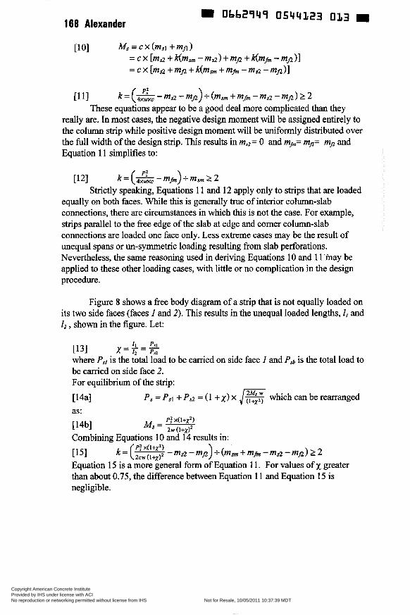
168 Alexander 9 Obb2949 0544323 013
PJ [ 1 i] k = (.ywxc - msz - mfl) t (m, + rnb - ms2 - mn) 2 2
These equations appear to be a good deal more complicated than they redly are. In most cases, the negative design moment will be assigned entirely to the column strip while positive design moment will be uniformly distributed over the full width of the design strip. This results in ms2= O and m,,= mfl= m, and Equation 11 simplifies to:
[12] k = (& - m h ) + msm 2 2 Strictly speaking, Equations 1 1 and 12 apply only to strips that are loaded
equally on both faces. While this is generally true of interior column-slab connections, there are circumstances in which this is not the case. For example, strips parallel to the free edge of the slab at edge and comer column-slab connections are loaded one face only. Less extreme cases may be the result of unequal spans or un-symmetric loading resulting from slab perforations. Nevertheless, the same reasoning used in deriving Equations 1 O and 1 1 may be applied to these other loading cases, with little or no complication in the design procedure.
Figure 8 shows a free body diagram of a strip that is not equally loaded on its two side faces (faces 1 and 2). This results in the unequal loaded lengths, I I and 1, , shown in the figure. Let:
II PYI i131 x='i;== where PSI is the total load to be carried on side face 1 and Psh is the total load to be carried on side face 2. For equilibrium of the strip:
~ 4 a 1 P , = Psi + Ps2 = (1 + x) x
PJ X ( l + X Z ) M , = -
which can be rearranged as:
[14b1 2w (i+# Combining Equations 1 O and 14 results in:
ri51 Equation 15 is a more general form of Equation 1 1. For values of x greater than about 0.75, the difference between Equation 1 1 and Equation 15 is negligible.
= (P? X(l+XZ) 2cw (i+x)2 m a - mp> + (msm + mr, - msz - mfl) 2 2
Copyright American Concrete Institute Provided by IHS under license with ACI Licensee=AECOM User Geography and Business Line/5906698001, User=Elmorsi, Mostaf
Not for Resale, 10/05/2011 10:37:39 MDTNo reproduction or networking permitted without license from IHS
--`,``,,`,,`,,,,`,``,,,`,`,,,`,-`-`,,`,,`,`,,`---
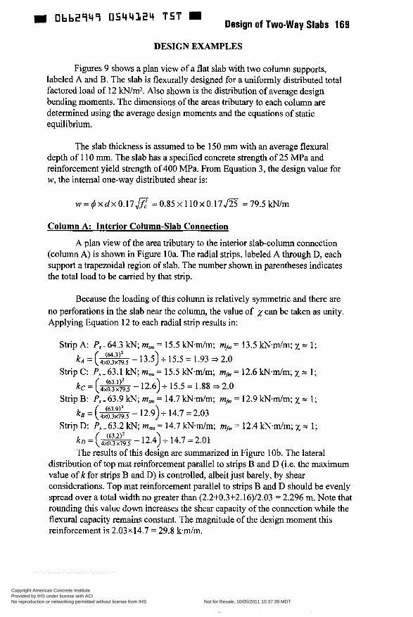
m Obb2949 0544124 T 5 T Design of Two-way Slabs 169
DESIGN EXAMPLES
Figures 9 shows a plan view of a flat slab with two column supports, labeled A and B. The slab is flexurally designed for a uniformly distributed total factored load of 12 kNím2. Also shown is the distribution of average design bending moments. The dimensions of the areas tributary to each column are determined using the average design moments and the equations of static equilibrium.
The slab thickness is assumed to be 150 mm with an average flexural depth of 1 10 mm. The slab has a specified concrete strength of 25 MPa and reinforcement yield strength of 400 MPa. From Equation 3, the design value for w, the internal one-way distributed shear is:
w = q3 x d x 0 . 1 7 E = 0.85 x 110 x 0 . 1 7 m = 79.5 kN/m
Column A: Interior Column-Slab Connection
A plan view of the area tributary to the interior slab-column connection [column A) is shown in Figure 1 Oa. The radial strips, labeled A through Dy each support a trapezoidal region of slab. The number shown in parentheses indicates the total load to be carried by that strip.
Because the loading of this column is relatively symmetric and there are no perforations in the slab near the column, the value of ,y can be taken as unity. Applying Equation 12 to each radial strip results in:
Strip A: P, = 64.3 kN; msni = 15.5 kN*m/m; mfnl = 13.5 k N d m ; x = 1;
Strip C: P,=63.1 kN; m, = 15.5 kNm/m; mfnl = 12.6 k N d m ; x = 1;
Strip B: Ps=63.9 kN; msnl = 14.7 kN*m/m; m,, = 12.9 kN.m/m; x = 1;
Strip D: P, = 63.2 kN; m,711, = 14.7 kNm/m; m,,, = 12.4 kNm/m; x = 1;
kA = (- - 13.5)+ 15.5 = 1.93 3 2.0
kc = (- - 12.6)+ 15.5 = 1.88 3 2.0
ks = (4xo1x79j- - 12.9) + 14.7 = 2.03
k D = (;ixo3;jgs. - 12.4) +- 14.7 = 2.01 The results of this design are summarized in Figure lob. The lateral
distribution of top mat reinforcement parallel to strips B and D (Le. the maximum value of k for strips B and D) is controlled, albeit just barely, by shear considerations. Top mat reinforcement parallel to strips B and D should be evenly spread over a total width no greater than (2.2+0.3+2.16)/2.03 = 2.296 m. Note that rounding this value down increases the shear capacity of the connection while the flexural capacity remains constant. The magnitude of the design moment this reinforcement is 2.03~14.7 = 29.8 k d m .
(63.1)’
(63.9)’
(63.2)’
Copyright American Concrete Institute Provided by IHS under license with ACI Licensee=AECOM User Geography and Business Line/5906698001, User=Elmorsi, Mostaf
Not for Resale, 10/05/2011 10:37:39 MDTNo reproduction or networking permitted without license from IHS
--`,``,,`,,`,,,,`,``,,,`,`,,,`,-`-`,,`,,`,`,,`---
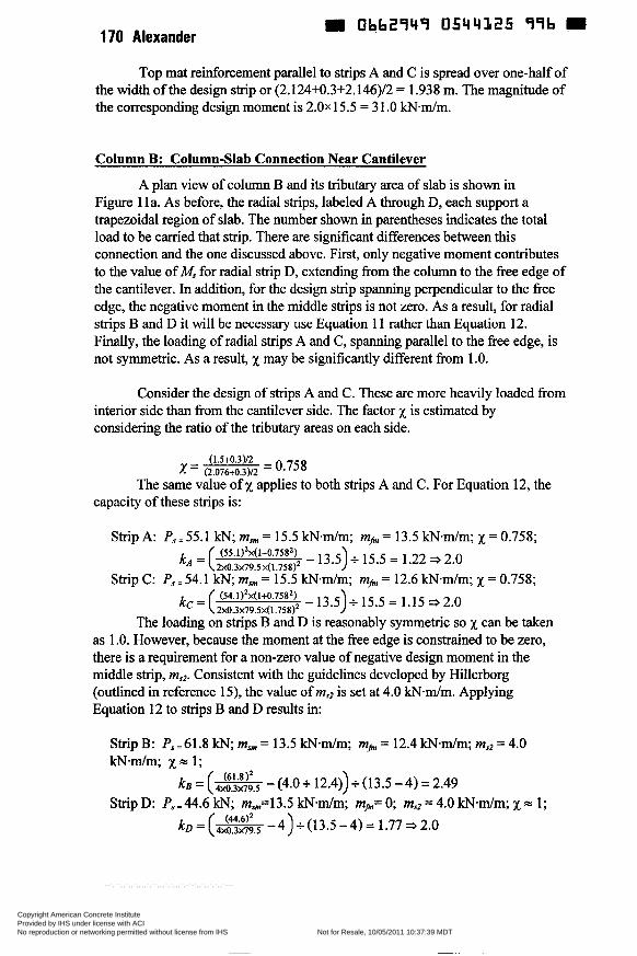
170 Alexander üb62949 0544L25 99b H
Top mat reinforcement parallel to strips A and C is spread over one-half of the width of the design strip or (2.124+0.3+2.146)/2 = 1.938 m. The magnitude of the corresponding design moment is 2 . 0 ~ 15.5 = 3 1 .O k N d m .
Column B: Column-Slab Connection Near Cantilever
A plan view of column B and its tributary area of slab is shown in Figure 1 la. As before, the radial strips, labeled A through D, each support a trapezoidal region of slab. The number shown in parentheses indicates the total load to be carried that strip. There are significant differences between this connection and the one discussed above. First, only negative moment contributes to the value of M, for radial strip Dy extending from the column to the free edge of the cantilever. In addition, for the design strip spanning perpendicular to the free edge, the negative moment in the middle strips is not zero. As a result, for radial strips B and D it will be necessary use Equation 1 1 rather than Equation 12. Finally, the loading of radial strips A and Cy spanning parallel to the free edge, is not symmetric. As a result, x may be significantly different from 1 .O.
Consider the design of strips A and C. These are more heavily loaded from interior side than from the cantilever side. The factor x is estimated by considering the ratio of the tributary areas on each side.
(1.5+0.3)/2 x = (2.076+0.3)/2 =
The same value of x applies to both strips A and C. For Equation 12, the capacity of these strips is:
Strip A: Ps=55.1 kN; m . , = 15.5 k N d m ; mh, = 13.5 k N d m ; x = 0.758; - 13.5)i 15.5 = 1.22 = 2.0 (55.1)2x(1+0.7582)
kA'( 2x0.3x79.5 ~ ( 1 . 7 5 8 ) ~
kc = ( (54'1)2x(1+0'7582) - 13.5)+ 15.5 = 1-15 j 2.0 Strip C: P.,=54.1 kN; msnl = 15.5 kN.m/m; mhl = 12.6 k N d m ; x = 0.758;
2x0.3~79.5xí1.758)~ The loading on strips B and D is reasonably symmetric so x can be taken
as 1 .O. However, because the moment at the free edge is constrained to be zero, there is a requirement for a non-zero value of negative design moment in the middle strip, m,,2. Consistent with the guidelines developed by Hillerborg (outlined in reference 15), the value of ms2 is set at 4.0 kN-m/m. Applying Equation 12 to strips B and D results in:
Strip B: Ps,61.8 kN; m, = 13.5 kN-dm; mhJ = 12.4 k N d m ; ms2 = 4.0 kN.m/m; x m 1;
B - -(--- 4xo.3x79,5 (4.0+ 12.4))+(13.5-4)=2.49 Strip D: P,=44.6 kN; mS,=13.5 k N d m ; mj,J= O; msz = 4.0 kN-m/m; x = 1;
k D = (*- 4><03x79.5 4)+(13.5-4)= 1 . 7 7 ~ 2 . 0
Copyright American Concrete Institute Provided by IHS under license with ACI Licensee=AECOM User Geography and Business Line/5906698001, User=Elmorsi, Mostaf
Not for Resale, 10/05/2011 10:37:39 MDTNo reproduction or networking permitted without license from IHS
--`,``,,`,,`,,,,`,``,,,`,`,,,`,-`-`,,`,,`,`,,`---
171
The resulting lateral distributions of design moment for column B are summarized in Figure i 1 b. As was the case for column A, the width of the column strip parallel to radial strips A and C is one-haif the width of the design strip. For column B, this is 1.938 m. The reinforcement in this column strip is designed for an average moment of 2 . 0 ~ 15.5 = 3 1 .O k N d m .
The width of the column strip parallel to radial strips B and D is controlled by shear considerations for radial strip B. The width of the column strip is (2.16+0.3+2.2)/2.49 = 1.871 m. The negative design moment in the middle strip, m,r2, is 4.0 k N d m . The negative design moment in the column strip, mSI, is (13.5 - 4.0) x 2.49 + 4.0 = 27.7 m.m/m.
CONCLUSION
The main components of a strip model for the plastic design of column-slab connections have been presented. The strip model accounts for the interplay of both slender and deep flexural behavior in the vicinity of column-slab connections.
As an analytical procedure, the strip model shows that the shear capacity of a column-slab connection is a function of both the one-way shear strength and the flexuraì strength of the slab in the vicinity of the column. When used to predict the failure strength of 145 punching tests reported in the literature, the strip model produced an average value for the ratio of test to predicted load of 1.3 with a coefficient of variation of 12.2%. On the same data, the AC1 code procedure produced an average value of 1.56 with a coefficient of variation of 26.2%.
In comparing the strip model with the AC1 code procedure, it is found that, as long as standard lateral distribution of reinforcement specified by the AC1 code is followed, the AC1 procedure should correctly predict if the punching strength is more or less than the flexural strength. This explains why the AC1 procedure is adequate as a design procedure even though it is a poor predictor of actual punching capacity.
When used as a design procedure, the strip model shows that adjusting the lateral distribution of flexural reinforcement is the most effective way to ensure adequate shear strength. The strip model therefore offers the designer a new strategy for dealing with the shear design of slab-column connections.
Copyright American Concrete Institute Provided by IHS under license with ACI Licensee=AECOM User Geography and Business Line/5906698001, User=Elmorsi, Mostaf
Not for Resale, 10/05/2011 10:37:39 MDTNo reproduction or networking permitted without license from IHS
--`,``,,`,,`,,,,`,``,,,`,`,,,`,-`-`,,`,,`,`,,`---
W Obb2949 0544327 7b9 172 Alexander
REFERENCES
1 Alexander, S.D.B. and Simmonds, S.H. 1992. Bond model for concentric punching shear. ACI Structural Journal, V. 89, No. 3, pp. 325-334.
AC1 Committee 3 18, 1995, Building code requirements for reinforced concrete. American Concrete Institute, Detroit.
Elstner, R.C., and Hognestad, E., "Shearing Strength of Reinforced Concrete Slabs," AC1 Journal, Proceedings, Vo1.53, No.1, July 1956, pp. 29-58.
Kinnunen, S., and Nylander, H., "Punching of Concrete Slabs Without Shear Reinforcement," Transactions of the Royal Institute of Technology (Sweden), No. 158, Stockholm, 1960, 112 pp.
Moe, J., "Shearing Strength of Reinforced Concrete Slabs and Footings Under Concentrated Loads," Development Department Bulletin No. D47, Portland Cement Association, Skokie, 1961, 130 pp.
Regan, P.E.; Walker, P.R.; Zakaria, K.A.A., "Tests of Reinforced Concrete Flat Slabs," CIRIA Project No. RP 220, Polytechnic of Central London, 1979,217 pp.
Rankin, G.I.B., and Long, A.E., "Predicting the Punching Strength of Conventional Slab-Column Specimens," Proceedings of the Institution of Civil Engineers, Part 1, Vo1.82, April 1987, pp. 327-346.
Gardner, N.J., "Relationship of the Punching Shear Capacity of Reinforced Concrete Slabs with Concrete Strength. AC1 Structural Journal, Vo1.87, No. 1 , Jan.-Feb. 1990, pp. 66-71.
Shilling, R.C., and Vanderbilt, M.D., "Behavior of Shear Test Structure," Structural Research Report No. 4, Colorado State University, Fort Collins, 1970,66 pp.
10 Lunt, B.G., "Shear Strength of Reinforced Concrete Slabs at Column Supports," PhD thesis, University of Witwatersrand, Johannesburg, 1988,292 PP.
11 Kuang, J.S. and Morley, C.T., 1992. Punching shear behavior of restrained reinforced concrete slabs. ACI Structural Journal, V. 89, No. 1, pp. 13 - 19.
12 Marzo&, H.M. and Hussein, A.,1991, Experimental investigation on the behavior of high-strength concrete slabs. ACI Structural Journal, V. 88,
13 Regan, P.E. 1983. Behaviour of reinforced concrete slabs. CIRIA Report 89, Construction Industry Research and Information Association, London, United Kingdom.
2
3
4
5
6
7
8
9
NO. 6, pp. 701-713.
Copyright American Concrete Institute Provided by IHS under license with ACI Licensee=AECOM User Geography and Business Line/5906698001, User=Elmorsi, Mostaf
Not for Resale, 10/05/2011 10:37:39 MDTNo reproduction or networking permitted without license from IHS
--`,``,,`,,`,,,,`,``,,,`,`,,,`,-`-`,,`,,`,`,,`---
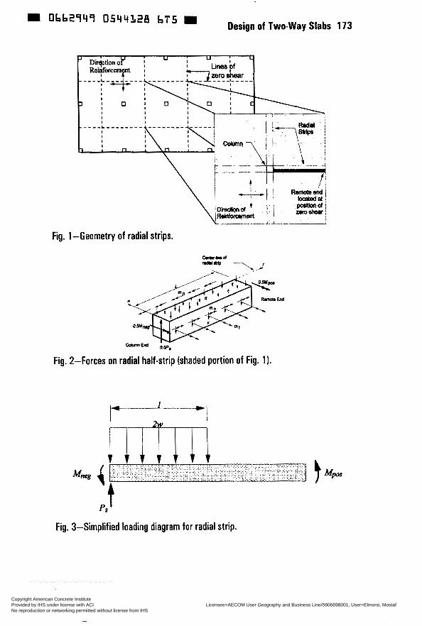
0544328 bT5 Design of Two-way Slabs 173
Fig. 1 -Geometry of radial strips.
Fig. 2-Forces on radial half-strip (shaded portion of Fig. 1).
ps'
Fig. 3-Simplified loading diagram for radial strip.
Copyright American Concrete Institute Provided by IHS under license with ACI Licensee=AECOM User Geography and Business Line/5906698001, User=Elmorsi, Mostaf
Not for Resale, 10/05/2011 10:37:39 MDTNo reproduction or networking permitted without license from IHS
--`,``,,`,,`,,,,`,``,,,`,`,,,`,-`-`,,`,,`,`,,`---

~~~
174 Alexander
* 8
i- 0.5
0.0
3.0
m
I 1 I I I
2.5
d u 2.0
ü Q
1.5
0.0 O I 2 3 4 5 0
Reinforcing Ratio (%)
(a) Results using strip model
Copyright American Concrete Institute Provided by IHS under license with ACI Licensee=AECOM User Geography and Business Line/5906698001, User=Elmorsi, Mostaf
Not for Resale, 10/05/2011 10:37:39 MDTNo reproduction or networking permitted without license from IHS
--`,``,,`,,`,,,,`,``,,,`,`,,,`,-`-`,,`,,`,`,,`---
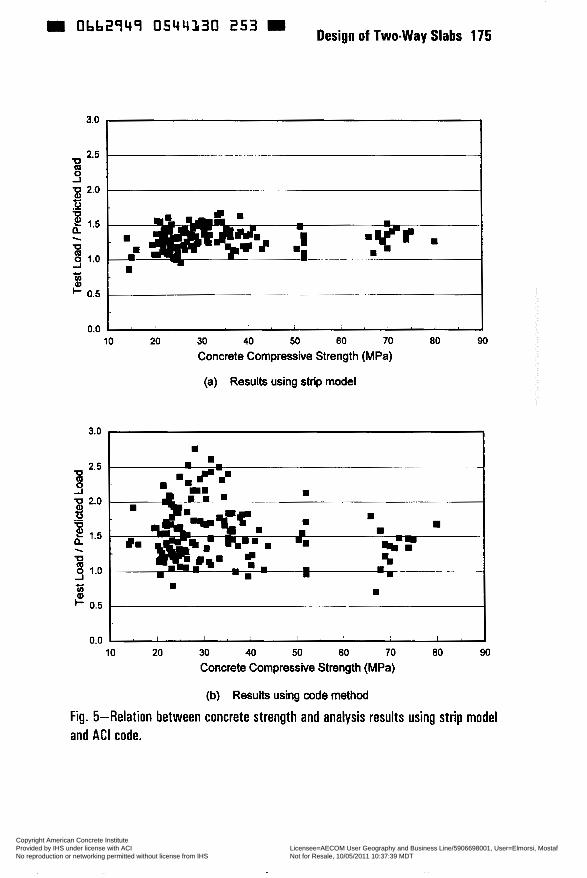
0bb2q4q 0544130 Design of Two-way Slabs 175
3.0
8
2.5 - -~ - U
m
i
__
.? -__ ~
Y
H W al
i- 0.5 ___
0.0 I . I , . , ! , I ,
3.0
2.5 U Q O -I p 2.0 ti 2 1.5
1.0
. U
-I
u> al i- 0.5
I
0.0
L- I
10 20 30 40 50 60 70 80 90 Concrete Compressive Strength (MPa)
(a) Results using strip model
Fig. 5-Relation between concrete strength and analysis results using strip model and AC1 code.
Copyright American Concrete Institute Provided by IHS under license with ACI Licensee=AECOM User Geography and Business Line/5906698001, User=Elmorsi, Mostaf
Not for Resale, 10/05/2011 10:37:39 MDTNo reproduction or networking permitted without license from IHS
--`,``,,`,,`,,,,`,``,,,`,`,,,`,-`-`,,`,,`,`,,`---
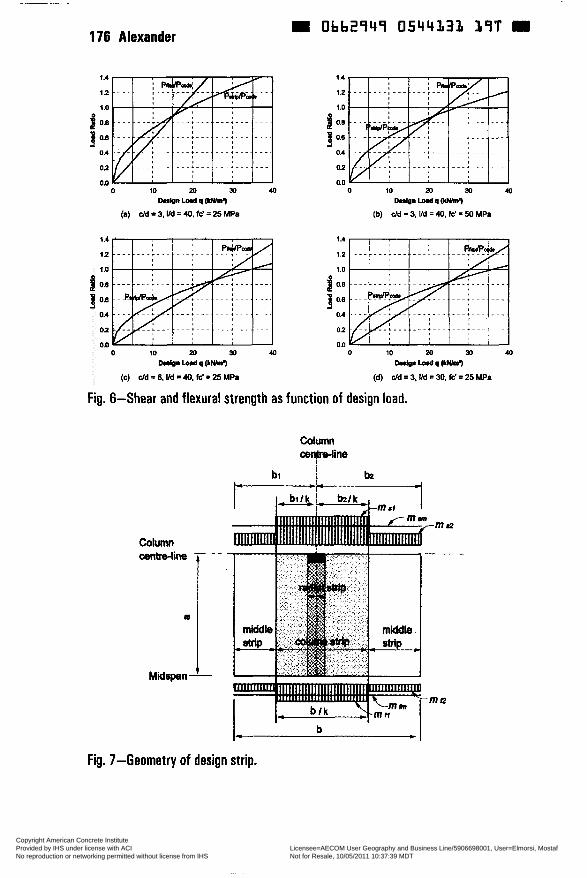
176 Alexander 9 Obb294î 0544131 1 î T
O 10 20 M Dabn L o d q Wml)
(a) cid = 3, IM = 40, fc' = 25 MPs
O 10 20 34 40 D..lpn-qpiwhn.)
(b) cid =3, Ild -40,fc' = 50 MPa
1.1
O 10 20 30 40 bior Lo*l q (LNhn.)
(e) cid =6. üd =4ü, W =25 MPa
Fig. 6-Shear and flexural strength a s
O 10 M 30 40
W n Lod o tuum7
(d) cid = 3, IM = 30. fc' = 25 MPa
function of design load.
Column cen)ine
j bi
Fig. 7-Geometry of design strip.
Copyright American Concrete Institute Provided by IHS under license with ACI Licensee=AECOM User Geography and Business Line/5906698001, User=Elmorsi, Mostaf
Not for Resale, 10/05/2011 10:37:39 MDTNo reproduction or networking permitted without license from IHS
--`,``,,`,,`,,,,`,``,,,`,`,,,`,-`-`,,`,,`,`,,`---
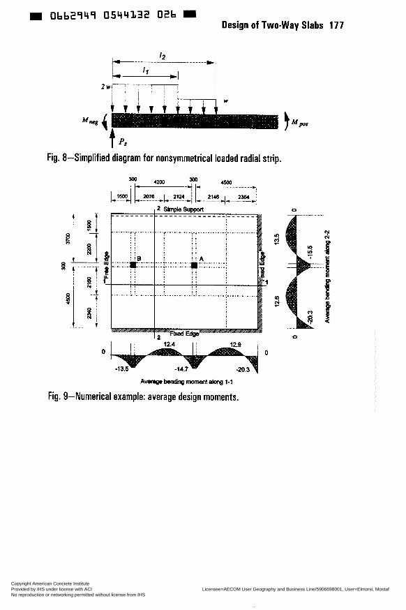
W Obb2949 0544132 Otb Design of Two-way Slabs 177
Fig. 8-Simplified diagram for nonsymmetrical loaded radial strip.
O O
o
O
A ~ ~ m o m e n t ~ l - 1
Fig. 9-Numerical example: average design moments.
Copyright American Concrete Institute Provided by IHS under license with ACI Licensee=AECOM User Geography and Business Line/5906698001, User=Elmorsi, Mostaf
Not for Resale, 10/05/2011 10:37:39 MDTNo reproduction or networking permitted without license from IHS
--`,``,,`,,`,,,,`,``,,,`,`,,,`,-`-`,,`,,`,`,,`---

m Obb2949 0544333 Tb2 m 178 Alexander
HU 3oo 2146 I- 4 I- -I 2
' g o c!
12.4 12.8 O O
(a) Average design moments and tributary area
12.6 (b) Lateral disinbuam of dedgn momenb
Fig. 1 O-Numerical example: Column A.
Copyright American Concrete Institute Provided by IHS under license with ACI Licensee=AECOM User Geography and Business Line/5906698001, User=Elmorsi, Mostaf
Not for Resale, 10/05/2011 10:37:39 MDTNo reproduction or networking permitted without license from IHS
--`,``,,`,,`,,,,`,``,,,`,`,,,`,-`-`,,`,,`,`,,`---
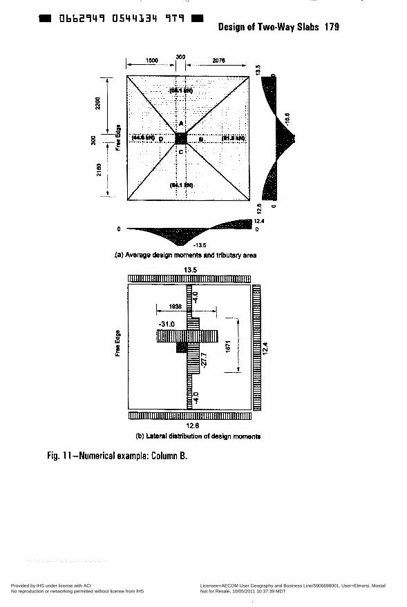
9 Ob62949 0544334 9T7 m Design of Two-way Slabs 179
2076 300 -' ? I I- m I- l5O0 -
12.4 O O
(a) Average design moments and tributary area
13.5
a
N s ? r Y
12.6 (b) Lateral distribution of design moments
Fig. 1 1 -Numerical example: Column B.
Copyright American Concrete Institute Provided by IHS under license with ACI Licensee=AECOM User Geography and Business Line/5906698001, User=Elmorsi, Mostaf
Not for Resale, 10/05/2011 10:37:39 MDTNo reproduction or networking permitted without license from IHS
--`,``,,`,,`,,,,`,``,,,`,`,,,`,-`-`,,`,,`,`,,`---
180 SI (Metric) Tables Obb2 î l l ï 0544135 835
CONVERSION FACTORS-INCH-POUND TO SI (METRIC)*
To convert from
inch foot
Yard mile (statute)
square inch
square foot
square yard
ounce
gallon
cubic inch
cubic foot
cubic yard
kilogram-force kip-force pound-force
kilogram-forceisquare meter kip-fordsquare inch (ksi)
newtorúsquare meter W/m2) pound-fodsquare foot pound-forceisquare inch (psi)
inch-pound-force foot-pound-force meter-kilogram-force
to
Length millimeter (mm) meter (m) meter (m)
kilometer (km)
ANS
square centimeter (cm2>
square meter (m2)
square meter (m2)
Volume (capacity)
cubic centimeter (cm3)
cubic meter (m3)$
cubic centimeter (cm3)
cubic meter (m’)
cubic meter (m3)$
Force newton (N) newton (N) newton (N)
Pressure or stm (force per area)
pascal (Pa) megapascal (MF’a)
pascal (Pa)
kilopascal (kPa) P a d (Pa)
Bending moment or torque newton-meter (Nm) newtonmeter (Nm) newton-meter (Nm)
multiply by
25.4Et 0.3048E 0.91448 1.609
6.45 1
0.0929
0.8361
29.51
0.003785
i 6.4
0.02832
0.7646
9.807 4448 4.448
9.807 6.895
1 .OOOE
41.88 6.895
0.1130 1.356 9.807
Copyright American Concrete Institute Provided by IHS under license with ACI Licensee=AECOM User Geography and Business Line/5906698001, User=Elmorsi, Mostaf
Not for Resale, 10/05/2011 10:37:39 MDTNo reproduction or networking permitted without license from IHS
--`,``,,`,,`,,,,`,``,,,`,`,,,`,-`-`,,`,,`,`,,`---
ubb2qYq 05Y4136 77L SI (Metric) Tables 181
To convert from
ounce-mass (avoirdupois) pound-mass (avoirdupois) ton (metric) ton (short, 2000 Ibm)
Mass per volume pound-masslcubic foot kilogram/cubic meter (kg/m3)
pound-masdcubic yard kilogram/cubic meter (kglrn’)
pound-masdgallon kilogradcubic meter (kg/m3)
deg Fahrenheit (F)
deg Celsius (C)
Temperaturea deg Celsius (C)
deg Fahrenheit (F)
multiply by
28.34 0.4536 1 .COJE 0.9072
16.02
0.5933
119.8
k = (tF - 32)/1.8
tF= 1.8k + 32
* This selected list gives practical conversion factors of units found in concrete technology. The reference source for information on SI units and more exact conversion factors is “Standard for Metric Practice” ASTM E 380. Symbols of metric units are given in parentheses. t E indicates that the factor given is exact. $ One liter (cubic decimeter) equals 0.001 m3 or loo0 cm3. 5 These equations convert one temperature reading to another and include the necessary scale corrections.
To convert a difference in temperature from Fahrenheit to Celsius degrees, divide by 1.8 only, ¡.e.. a change from 70 to 88 F represents a change of i 8 For 18/1.8 = IO C.
Copyright American Concrete Institute Provided by IHS under license with ACI Licensee=AECOM User Geography and Business Line/5906698001, User=Elmorsi, Mostaf
Not for Resale, 10/05/2011 10:37:39 MDTNo reproduction or networking permitted without license from IHS
--`,``,,`,,`,,,,`,``,,,`,`,,,`,-`-`,,`,,`,`,,`---
W Ob62949 0544337 bOô 9
A-B Alexander, S., 93, 161 analysis, 1,77
C collapse load analysis, 67 columns (supports), 37,93,119,161 connections, 37 cracking, 145
D deflection control, 145 design, 1,17,77,93,145 detailing, 131 ductility, 37 dynamic analysis, 17
E elastic frames, 1 equilibrium. 77
finite element analysis, 131 footings, 37 frame method, 119
F
INDEX
G Gamble, W., 67,119 Chali, A., 37
H
I- J
K
L
M-N-O
P-Q
history. 1
in-plane forces, 67
Krauthammer. T.. 17
lateral loads, 119
Megally. S. , 37
plates, 93 plasticity, 77 prestressed concrete. 37 punching shear, 37,161
Index 183
R reinforced concrete, 17,37,77, 161 reinforced concrete design, 131 reinforced concrete slabs, 1,93 Rogowsky, D., 131
S-T-U-V Scanlon. A., 145 segment. 77 seismic design. 37 shear strength, 37 Simmonds, S., 1,7? slabs, 37,67,77,119,131,145,161 strip method. 77 StNChld design, 37 StNChld Steel. 17
w-x
Y-z Woodson, S., 17
yield line, 77 yield line analysis. 67 yield mechanisms, 67
Copyright American Concrete Institute Provided by IHS under license with ACI Licensee=AECOM User Geography and Business Line/5906698001, User=Elmorsi, Mostaf
Not for Resale, 10/05/2011 10:37:39 MDTNo reproduction or networking permitted without license from IHS
--`,``,,`,,`,,,,`,``,,,`,`,,,`,-`-`,,`,,`,`,,`---