ACI Constructs Design -...
42
ACI Constructs Design • Common Tenant and User-Configured Tenant Policy Usage, page 1 • Common Pervasive Gateway, page 4 • Contracts and Policy Enforcement, page 7 • Contract Labels, page 13 • Taboo Contracts, page 16 • Bridge Domains, page 17 • Application-Centric and Network-Centric Deployments, page 22 • Layer 2 Extension, page 26 • Infrastructure VXLAN Tunnel Endpoint Pool, page 28 • Virtual Routing and Forwarding Instances, page 30 • Stretched Fabric, page 30 • Access Policies, page 32 • Managed Object Naming Convention , page 42 Common Tenant and User-Configured Tenant Policy Usage About Common Tenant and User-Configured Tenant Policy Usage A tenant is a logical container for application, networking and security policies. The rules governing policy reuse across tenants differ between user-configured tenants and the system-defined common tenant. An example would be that user-configured tenant "A" has a bridge domain, while user-configured tenant "B" has an endpoint group. By default, tenant B's endpoint group will never be able to make an association to tenant A's bridge domain. Objects within user-configured tenants cannot form relationships with objects in other user-configured tenants unless specified with explicit configurations. One example of this is the process of exporting a contract from one user-configured tenant to another. Otherwise, that contract can only be referenced by other objects within the same tenant. Cisco Application Centric Infrastructure Best Practices Guide 1
Transcript of ACI Constructs Design -...

ACI Constructs Design
• Common Tenant and User-Configured Tenant Policy Usage, page 1
• Common Pervasive Gateway, page 4
• Contracts and Policy Enforcement, page 7
• Contract Labels, page 13
• Taboo Contracts, page 16
• Bridge Domains, page 17
• Application-Centric and Network-Centric Deployments, page 22
• Layer 2 Extension, page 26
• Infrastructure VXLAN Tunnel Endpoint Pool, page 28
• Virtual Routing and Forwarding Instances, page 30
• Stretched Fabric, page 30
• Access Policies, page 32
• Managed Object Naming Convention , page 42
Common Tenant and User-Configured Tenant Policy Usage
About Common Tenant and User-Configured Tenant Policy UsageA tenant is a logical container for application, networking and security policies. The rules governing policyreuse across tenants differ between user-configured tenants and the system-defined common tenant.
An example would be that user-configured tenant "A" has a bridge domain, while user-configured tenant "B"has an endpoint group. By default, tenant B's endpoint group will never be able to make an association totenant A's bridge domain. Objects within user-configured tenants cannot form relationships with objects inother user-configured tenants unless specified with explicit configurations. One example of this is the processof exporting a contract from one user-configured tenant to another. Otherwise, that contract can only bereferenced by other objects within the same tenant.
Cisco Application Centric Infrastructure Best Practices Guide 1

When utilizing the system-generated tenant common, this rule does not apply. Objects within tenant commoncan be accessed by all other tenants within a Cisco Application Centric Infrastructure (ACI) fabric. This meansthat tenant B's endpoint group would be able to use a bridge domain configured within tenant common.Similarly, tenant B's endpoint group would be able to use a contract that exists within tenant common withoutneeding to be exported.
Prerequisites for Common Tenant and User-Configured Tenant Policy UsageYou must meet the following prerequisites to use the common tenant and user-configured tenant policies:
• Tenant common is system generated and has no prerequisite configuration to allow its policies to beaccessed by other tenants.
• A user-configured tenant must be created before usage. Not all user-configured tenant policies can bemade accessible to other tenants. The following policies can be exported from one user-configured tenantto another to form a relationship:
◦Contracts
◦Layer 4 to Layer 7 devices
Guidelines and Limitations for Common Tenant and User-Configured TenantPolicy Usage
The following guidelines and limitations apply for common tenant and user-configured tenant policy usage:
• There are specific policies within a user-configured tenant that can be exported to another tenant forrelationship usage.
• A VRF named "myVRF" within user-configured tenant A is not the same as a VRF named "myVRF"within user-configured tenant B. This difference can be observed by looking at the distinguished name(DN) of both VRFs.
• Depending on the intended usage of these exported policies, there might be other configuration changesrequired to complete inter-tenant communication. For more information, see About Shared Services.
Recommended Configuration Procedure for Common Tenant andUser-Configured Tenant Policy Usage
The following procedure exports contracts and Layer 4 to Layer 7 devices from a user-configured tenant usingthe Application Policy Infrastructure Controller (APIC) GUI, which you can then import into anotheruser-configured tenant. You must use the advanced GUI mode.
Cisco Application Centric Infrastructure Best Practices Guide2
ACI Constructs DesignPrerequisites for Common Tenant and User-Configured Tenant Policy Usage
Procedure
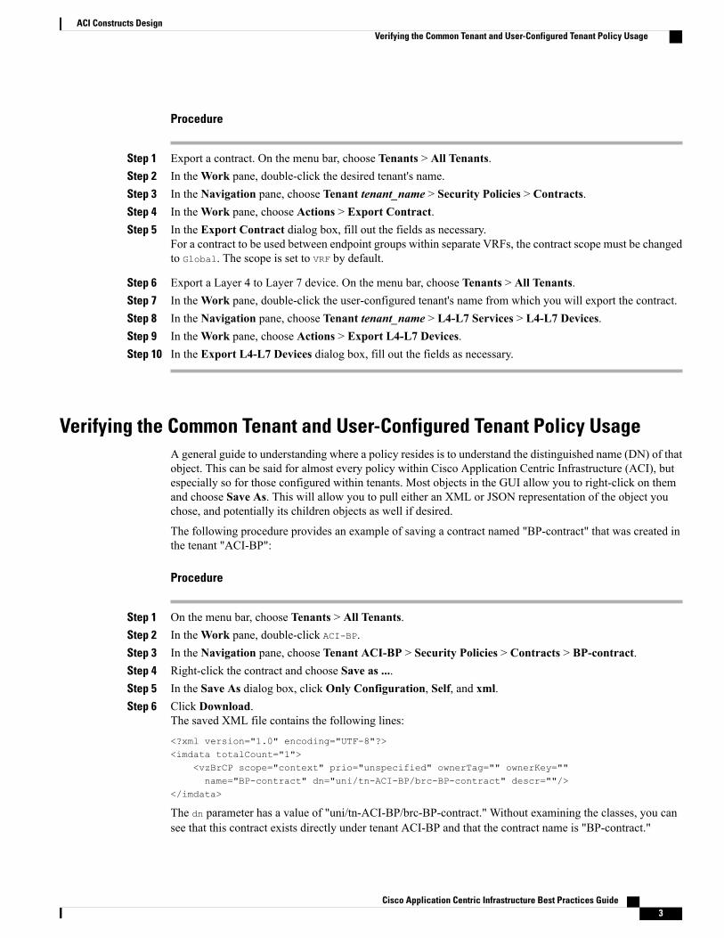
Step 1 Export a contract. On the menu bar, choose Tenants > All Tenants.Step 2 In theWork pane, double-click the desired tenant's name.Step 3 In the Navigation pane, choose Tenant tenant_name > Security Policies > Contracts.Step 4 In theWork pane, choose Actions > Export Contract.Step 5 In the Export Contract dialog box, fill out the fields as necessary.
For a contract to be used between endpoint groups within separate VRFs, the contract scope must be changedto Global. The scope is set to VRF by default.
Step 6 Export a Layer 4 to Layer 7 device. On the menu bar, choose Tenants > All Tenants.Step 7 In theWork pane, double-click the user-configured tenant's name from which you will export the contract.Step 8 In the Navigation pane, choose Tenant tenant_name > L4-L7 Services > L4-L7 Devices.Step 9 In theWork pane, choose Actions > Export L4-L7 Devices.Step 10 In the Export L4-L7 Devices dialog box, fill out the fields as necessary.
Verifying the Common Tenant and User-Configured Tenant Policy UsageA general guide to understanding where a policy resides is to understand the distinguished name (DN) of thatobject. This can be said for almost every policy within Cisco Application Centric Infrastructure (ACI), butespecially so for those configured within tenants. Most objects in the GUI allow you to right-click on themand choose Save As. This will allow you to pull either an XML or JSON representation of the object youchose, and potentially its children objects as well if desired.
The following procedure provides an example of saving a contract named "BP-contract" that was created inthe tenant "ACI-BP":
Procedure
Step 1 On the menu bar, choose Tenants > All Tenants.Step 2 In theWork pane, double-click ACI-BP.Step 3 In the Navigation pane, choose Tenant ACI-BP > Security Policies > Contracts > BP-contract.Step 4 Right-click the contract and choose Save as ....Step 5 In the Save As dialog box, click Only Configuration, Self, and xml.Step 6 Click Download.
The saved XML file contains the following lines:
<?xml version="1.0" encoding="UTF-8"?><imdata totalCount="1">
<vzBrCP scope="context" prio="unspecified" ownerTag="" ownerKey=""name="BP-contract" dn="uni/tn-ACI-BP/brc-BP-contract" descr=""/>
</imdata>
The dn parameter has a value of "uni/tn-ACI-BP/brc-BP-contract." Without examining the classes, you cansee that this contract exists directly under tenant ACI-BP and that the contract name is "BP-contract."
Cisco Application Centric Infrastructure Best Practices Guide 3
ACI Constructs DesignVerifying the Common Tenant and User-Configured Tenant Policy Usage
Configuration Examples for Common Tenant and User-Configured Tenant PolicyUsage
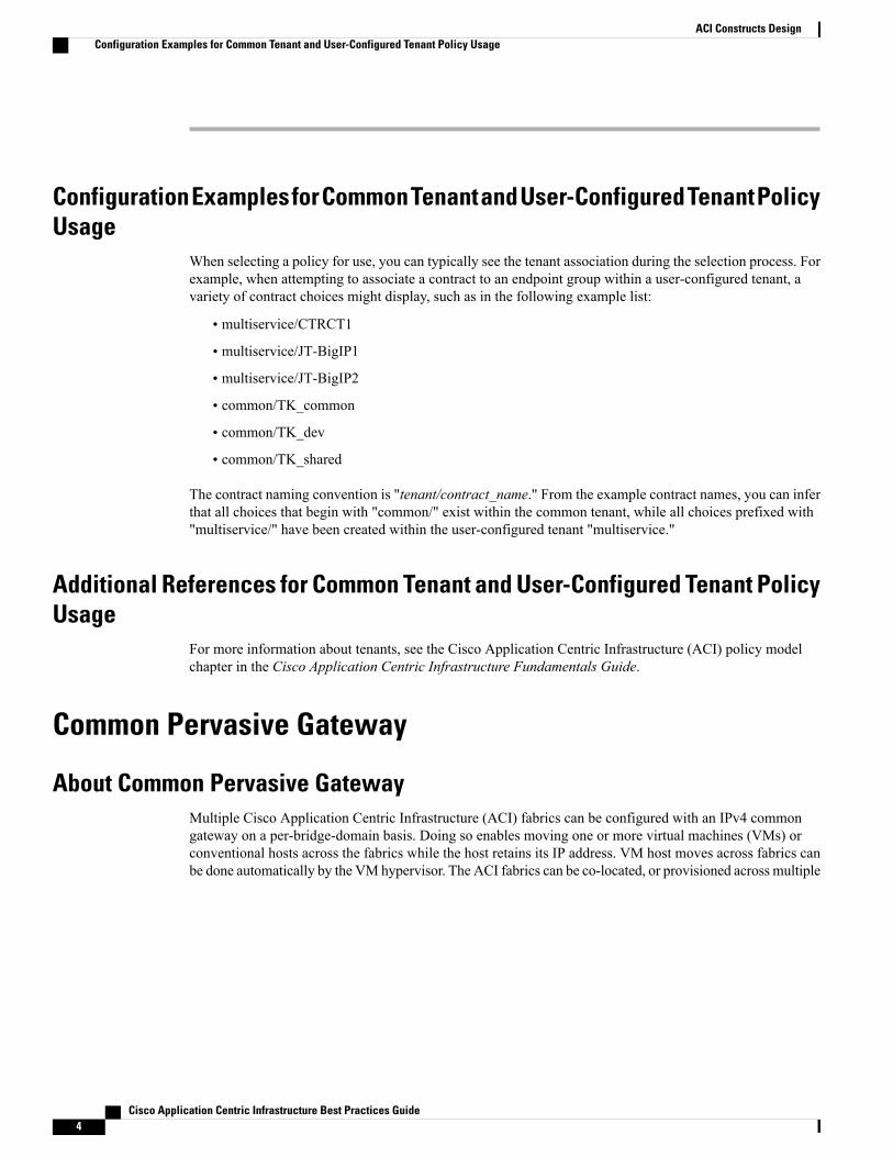
When selecting a policy for use, you can typically see the tenant association during the selection process. Forexample, when attempting to associate a contract to an endpoint group within a user-configured tenant, avariety of contract choices might display, such as in the following example list:
• multiservice/CTRCT1
• multiservice/JT-BigIP1
• multiservice/JT-BigIP2
• common/TK_common
• common/TK_dev
• common/TK_shared
The contract naming convention is "tenant/contract_name." From the example contract names, you can inferthat all choices that begin with "common/" exist within the common tenant, while all choices prefixed with"multiservice/" have been created within the user-configured tenant "multiservice."
Additional References for Common Tenant and User-Configured Tenant PolicyUsage
For more information about tenants, see the Cisco Application Centric Infrastructure (ACI) policy modelchapter in the Cisco Application Centric Infrastructure Fundamentals Guide.
Common Pervasive Gateway
About Common Pervasive GatewayMultiple Cisco Application Centric Infrastructure (ACI) fabrics can be configured with an IPv4 commongateway on a per-bridge-domain basis. Doing so enables moving one or more virtual machines (VMs) orconventional hosts across the fabrics while the host retains its IP address. VM host moves across fabrics canbe done automatically by the VM hypervisor. The ACI fabrics can be co-located, or provisioned across multiple
Cisco Application Centric Infrastructure Best Practices Guide4
ACI Constructs DesignConfiguration Examples for Common Tenant and User-Configured Tenant Policy Usage

sites. The Layer 2 connection between the ACI fabrics can be a local link, or can be across a routed WANlink. The following figure illustrates the basic common pervasive gateway topology:
Figure 1: Common Pervasive Gateway Topology
Prerequisites for Common Pervasive GatewayYou must meet the following prerequisites to use common pervasive gateway (CPG):
• Subnets should be determined for CPG
• Common vMAC and unique pMACs across fabrics should be determined
• Hosts to utilize CPG should be set to use the VIP gateway address
• Layer 2 connectivity between fabrics should be established
Guidelines and Limitations for Common Pervasive GatewayThe following guidelines and limitations apply for common pervasive gateway (CPG):
• The bridge domain MAC (pMAC) values for each fabric must be unique.
The default bridge domain MAC (pMAC) address values are the same for all Cisco Application CentricInfrastructure (ACI) fabrics. The common pervasive gateway requires an administrator to configure thebridge domain MAC (pMAC) values to be unique for each ACI fabric.
• The bridge domain virtual MAC (vMAC) address and the subnet virtual IP address must be the sameacross all ACI fabrics for that bridge domain.Multiple bridge domains can be configured to communicateacross connected ACI fabrics. The virtual MAC address and the virtual IP address can be shared acrossbridge domains.
• For endpoints residing off bridge domains with a CPG, the fabric will only route traffic that hits thebridge domain by utilizing the vMAC. Any traffic utilizing the pMAC upon entry of the ACI fabric thatis destined for an EP will not be routed. This is normally not a concern if the source device is utilizingARP lookups before sending a reply, as the gateway entry for the end device should be the VIP/vMAC
Cisco Application Centric Infrastructure Best Practices Guide 5
ACI Constructs DesignPrerequisites for Common Pervasive Gateway

combo. Traffic sourced from the ACI bridge domain will always exit the fabric by utilizing the pMAC,not the vMAC. This will cause certain appliances to have communication issues when utilizing specificforwarding features that bypass ARP lookup and instead use the src_mac as the dst_mac in the reply.The following list contains examples of features that bypass ARP lookup:
◦EMC "Packet Reflect"
◦F5 "Auto Last Hop"
◦Netapp "Fast Path"
Recommended Configuration Procedure for Common Pervasive GatewayThe following information applies when configuring common pervasive gateway (CPG):
• Ensure that all end devices utilizing a CPG as its gateway should perform ARP lookups in allcommunication scenarios. Any device that utilizes some feature that bypasses this lookup will havecommunication issues when trying to get to another subnet within the fabric.
• The pMAC for bridge domains across two separate Cisco Application Centric Infrastructure (ACI)fabrics are unique.
• The vMAC across matching bridge domains should be configured the same across both ACI fabrics thatare utilizing CPG.
• The VIP address will be set as a virtual IP and will act as the gateway for hosts within this subnet.
Verifying the Common Pervasive Gateway Using the GUIThe following procedure verifies the common pervasive gateway (CPG) configuration using the ApplicationPolicy Infrastructure Controller (APIC) GUI.
Procedure
Step 1 On the menu bar, choose Tenants > All Tenants.Step 2 In theWork pane, double-click the desired tenant's name.Step 3 In the Navigation pane, choose Tenant tenant_name > Networking > Bridge Domains >
bridge_domain_name.Step 4 In theWork pane, choose the Policy > L3 Configurations tabs.
The Work pane displays the configuration pieces that are needed for a common pervasive gateway.
Step 5 The CustomMAC Address field is the pMAC that must be unique between both Cisco Application CentricInfrastructure (ACI) fabrics sharing the CPG. By default, all ACI fabrics have the same value. If the value isthe same for both fabrics, change the value either of the fabrics.
Step 6 The Virtual MAC Address field is the vMAC that must be the same between both bridge domains acrossboth ACI fabrics. Replace the “Not Configured” text with a valid MAC address.
Step 7 Put a check in the Treat as virtual IP address check box to define the subnet to be the VIP address underthe bridge domain.
Cisco Application Centric Infrastructure Best Practices Guide6
ACI Constructs DesignRecommended Configuration Procedure for Common Pervasive Gateway

This should be done for the address that will be shared across both bridge domains and act as the GW forhosts on this subnet. Otherwise, another subnet/bridge domain address will need to be created that is uniqueto this fabric. For example, assume that 192.168.1.1 will be the VIP and exist as the virtual IP address on bothfabrics' bridge domains. Fabric 1 will have a second subnet under the bridge domain set as 192.168.1.2, andFabric 2 will have a second subnet under the bridge domain set as 192.168.1.3. These second subnets will notbe virtual IPs, but instead will act as the bridge domain SVI.
Additional References for Common Pervasive GatewayFor more information on the common pervasive gateway traffic flow, see the tenants chapter of theOperatingCisco Application Centric Infrastructure document at the following URL:
http://www.cisco.com/c/en/us/support/cloud-systems-management/application-policy-infrastructure-controller-apic/tsd-products-support-series-home.html
Contracts and Policy Enforcement
About Contracts and Policy Enforcement
Contracts
By default, a VRF is in enforced mode, which means that without a contract, different endpoint groups areunable to communicate to each other. Endpoint groups associate to a contract with provider/consumerrelationships. ACLs, rules, and filters are created in the leaf switches to realize the intent of contracts that willbe programmed on the ternary content-addressable memory (TCAM). The following figure illustrates endpointgroups communicating through contracts:
Figure 2: Endpoint Group Communication Through Contracts
Policy information in Cisco Application Centric Infrastructure (ACI) is programmed into two TCAM tables:
• Policy TCAM contains entries for the allowed endpoint-group-to-endpoint-group traffic
Cisco Application Centric Infrastructure Best Practices Guide 7
ACI Constructs DesignAdditional References for Common Pervasive Gateway

• App TCAM contains shared destination Layer 4 port ranges
The size of the policy TCAM depends on the generation of Cisco ASIC that is in use. For ALE-based systems,the policy TCAM size is 4k entries. For ALE2-based systems, 32k hardware entries are available. In certainlarger scale environments, it is important to take policy TCAM usage into account and ensure that the limitsare not exceeded.
TCAM entries are generally specific to each endpoint group pair. In other words, even if the same contractis reused, new TCAM entries are installed for every pair of endpoint groups, as shown in the following figure:
Figure 3: TCAM Entries Per Endpoint Group Pair
An approximate calculation for the number of TCAM entries is as follows:Number of entries in a contract * Number of Consumer EPGs * Number of Provider EPGs * 2
vzAny
The "Any" endpoint group is a collection of all of the endpoint groups within a context, which is also knownas a virtual routing and forwarding (VRF), that allows for a shorthand way to refer to all of the endpoint groupswithin that context. This shorthand referral eases management by allowing for a single point of contractconfiguration for all endpoint groups within a context, and also optimizes hardware resource consumption byapplying the contract to this one group rather than to each endpoint group individually.
Cisco Application Centric Infrastructure Best Practices Guide8
ACI Constructs DesignAbout Contracts and Policy Enforcement
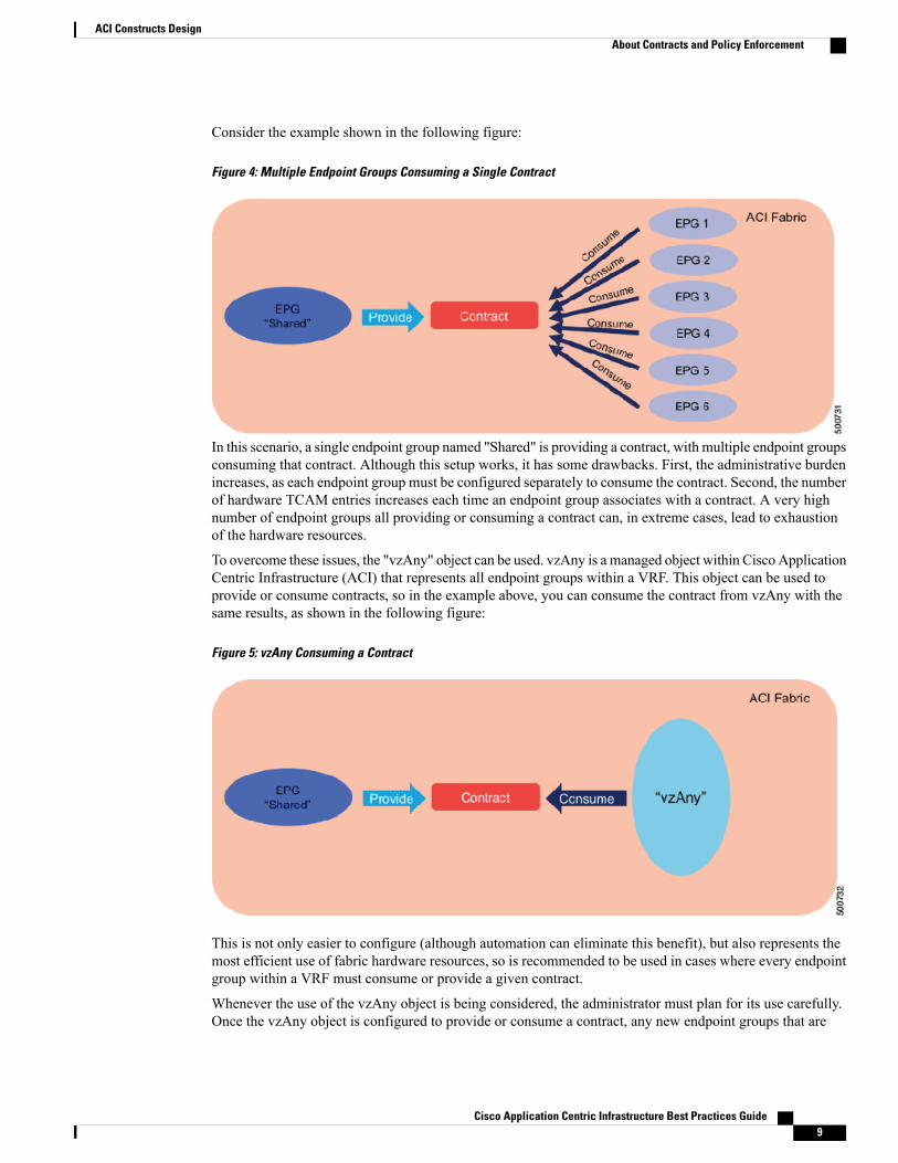
Consider the example shown in the following figure:
Figure 4: Multiple Endpoint Groups Consuming a Single Contract
In this scenario, a single endpoint group named "Shared" is providing a contract, with multiple endpoint groupsconsuming that contract. Although this setup works, it has some drawbacks. First, the administrative burdenincreases, as each endpoint group must be configured separately to consume the contract. Second, the numberof hardware TCAM entries increases each time an endpoint group associates with a contract. A very highnumber of endpoint groups all providing or consuming a contract can, in extreme cases, lead to exhaustionof the hardware resources.
To overcome these issues, the "vzAny" object can be used. vzAny is a managed object within Cisco ApplicationCentric Infrastructure (ACI) that represents all endpoint groups within a VRF. This object can be used toprovide or consume contracts, so in the example above, you can consume the contract from vzAny with thesame results, as shown in the following figure:
Figure 5: vzAny Consuming a Contract
This is not only easier to configure (although automation can eliminate this benefit), but also represents themost efficient use of fabric hardware resources, so is recommended to be used in cases where every endpointgroup within a VRF must consume or provide a given contract.
Whenever the use of the vzAny object is being considered, the administrator must plan for its use carefully.Once the vzAny object is configured to provide or consume a contract, any new endpoint groups that are
Cisco Application Centric Infrastructure Best Practices Guide 9
ACI Constructs DesignAbout Contracts and Policy Enforcement

associated with the VRF will inherit the policy; a new endpoint group added to the VRF will provide orconsume the same contracts that are configured under vzAny. If it is likely that new endpoint groups willneed to be added later and which might not need to consume the same contract as every other endpoint groupin the VRF, then vzAny might not be the most suitable choice. You should carefully consider this situationbefore you use vzAny.
To apply a contract to the vzAny group, choose a tenant in the Application Policy Infrastructure Controller(APIC) GUI. In the Navigation pane, navigate to Tenant tenant_name > Networking > VRFs > vrf_name> EPG Collection for Context. vrf_name is the name of the VRF for which you want to configure vzAny.EPG Collection for Context is the vzAny object; contracts can be applied here.
Using vzAny with the "Established Flag"
An additional example of the use of the vzAny policy to reduce resource consumption is to use it in conjunctionwith the "established" flag. By doing so, you can configure contracts as unidirectional in nature, which furtherreduces hardware resource consumption.
Consider the example shown in the following figure:
Figure 6: Bi-Directional Contracts - Regular Configuration
In this example, two contracts are configured for SSH and HTTP. Both contracts are provided by EPG2 andconsumed by EPG1. The Apply Both Directions and Reverse Filter Ports options are checked, resulting inthe four TCAM entries shown in the figure.
Cisco Application Centric Infrastructure Best Practices Guide10
ACI Constructs DesignAbout Contracts and Policy Enforcement
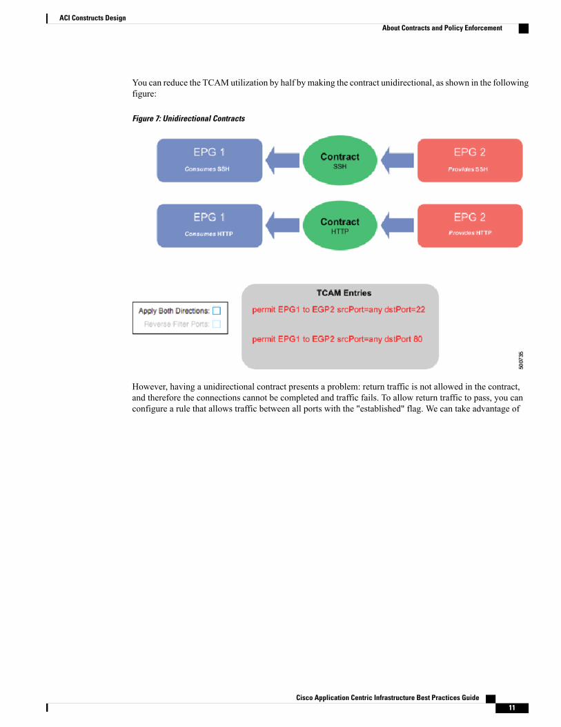
You can reduce the TCAMutilization by half by making the contract unidirectional, as shown in the followingfigure:
Figure 7: Unidirectional Contracts
However, having a unidirectional contract presents a problem: return traffic is not allowed in the contract,and therefore the connections cannot be completed and traffic fails. To allow return traffic to pass, you canconfigure a rule that allows traffic between all ports with the "established" flag. We can take advantage of
Cisco Application Centric Infrastructure Best Practices Guide 11
ACI Constructs DesignAbout Contracts and Policy Enforcement

vzAny in this case to configure a single contract for the "established" traffic and apply it to the entire VRF,as shown in the following figure:
Figure 8: Use of vzAny with an "Established" Contract
In an environment with a large number of contracts being consumed and provided, this can reduce the numberof TCAM entries significantly.
Ingress Policy Enforcement for Border Leaf TCAM Scalability
Software release 1.2 introduced a new policy enforcement model whereby security rules for all flows areenforced on the leaf node to which internal hosts are connected, rather than at the border leaf. This results ina more even distribution of security rules, rather than being concentrated at the border leaf as was the caseprior to release 1.2.
For more information, see About L3Out Ingress Policy Enforcement.
Guidelines and Limitations for Contracts and Policy EnforcementThe following guidelines and limitations apply when using a vzAny contract:
•When vzAny is used with a contract with scope = Application-Profile, this setting causes rule expansionin the leaf switches and therefore is not recommended
Cisco Application Centric Infrastructure Best Practices Guide12
ACI Constructs DesignGuidelines and Limitations for Contracts and Policy Enforcement

• vzAny is supported as a consumer of a shared service, but is not supported as a provider of a sharedservice
• vzAny is used only to optimize the specification of a source endpoint group or destination endpointgroup, by specifying a wildcard for either or both endpoint groups.
• If there are ranges in the filter with a vzAny contract, the port range will be done in TCAM to implementthe ranges
Additional References for Contracts and Policy EnforcementFor more information about contracts, including procedures for administering contracts, see the OperatingCisco Application Centric Infrastructure document at the following URL:
http://www.cisco.com/c/en/us/support/cloud-systems-management/application-policy-infrastructure-controller-apic/tsd-products-support-series-home.html
Contract Labels
About Contract LabelsContracts are key objects within the Cisco Application Centric Infrastructure (ACI) policy model to expressintended communication flows. Endpoint groups can only communicate with other endpoint groups accordingto the contract rules. A contract can be thought of as an ACL that opens ports between endpoint groups. Anadministrator uses a contract to select the types of traffic that can pass between endpoint groups, includingthe protocols and ports allowed. If there are no contracts connecting two endpoint groups, inter-endpointgroup communication is disabled by default as long as the VRF is set to Enforced. This is a representationof the white-list policy model that ACI is built around. There is no contract required for intra-endpoint groupcommunication; intra-endpoint group communication is always implicitly allowed regardless of VRF settings.There are configurations that can block intra-endpoint group communication, but is provided bymicrosegmentation and is not covered in this section.
Contracts can contain multiple communication rules, and multiple endpoint groups can both consume andprovide multiple contracts. Labels allow for control over which subjects and filters to apply whencommunicating between a specific pair of endpoint groups. Without labels, a contract will apply every subjectand filter between consumer and provider endpoint groups. A policy designer can use labels to compactlyrepresent a complex communication scenario, within the scope of a single contract, then re-use this contractwhile specifying only a subset of its policies across multiple endpoint groups.
Prerequisites for Contract LabelsYou must meet the following prerequisites to use contract labels:
• Contracts should be configured
• Depending on the type of matching to be done, the contract can contain multiple subjects (for subjectlabels to be useful)
• Have an understanding of the scope of the contract and how to change that setting (the default is VRF)
Cisco Application Centric Infrastructure Best Practices Guide 13
ACI Constructs DesignAdditional References for Contracts and Policy Enforcement
Guidelines and Limitations for Contract LabelsThe following guidelines and limitations apply for contract labels:
• Understand the scope of a label. Labels can be applied to a variety of provider and consumer managedobjects. This includes endpoint groups, contracts, bridge domains, DHCP relay policies, and DNSpolicies. Labels do not apply across object types; a label on an application endpoint group has no relevanceto a label on a bridge domain.
• Labels are managed objects with only one property: a name. Labels enable the classification of whichobjects can and cannot communicate with one another. Label matching is done first. If the labels do notmatch, no other contract or filter information is processed.
• Label matching can be applied based on logical operators. The label match attribute can be one of thesevalues: at least one (the default), all, none, or exactly one.
• Because labels are named references, do not to use duplicate label names unless the intent is to chainthose flows together.
Recommended Configuration Procedure for Contract LabelsIn general, contract labels are not required for contract deployments. For these general scenarios, a singleflow can be presented per contract (single subject/group of filters specific to that flow). Utilizing labels doesnot save resources compared to defining distinct contracts; labels are only another method available to provisioncontracts while defining specific flows.
Verifying the Contract Labels Using the GUIThe following procedure verifies the programmed rules of a contract under the EPG by using the ApplicationPolicy Infrastructure Controller (APIC) GUI. You can use either the advanced basic GUI mode.
Procedure
Step 1 On the menu bar, choose Tenants > All Tenants.Step 2 In theWork pane, double-click the tenant's name.Step 3 In the Navigation pane, choose Tenant tenant_name > Application Profiles > application_profile_name
> Application EPGs > EPG EPG_name.Step 4 In theWork pane, choose the Operational > Contracts tabs.
TheWork pane displays programmed rules for the contracts. You can ensure that the contract labels areconfigured properly.
Cisco Application Centric Infrastructure Best Practices Guide14
ACI Constructs DesignGuidelines and Limitations for Contract Labels
Configuration Examples for Contract LabelsThe following procedure provides an example of configuring contract labels using the Application PolicyInfrastructure Controller (APIC) GUI.
Procedure
Step 1 Configure contract labels (consumer and provider). On the menu bar, choose Tenants > All Tenants.Step 2 In theWork pane, double-click the tenant's name.Step 3 In the Navigation pane, choose Tenant tenant_name > Security Policies > Contracts > contract_name >
contract_subject_name.Step 4 In theWork pane, choose the Policy > Label tabs.
TheWork pane displays the existing consumed and provided contract labels, and you can configure newlabels.
Step 5 Configure endpoint group subject labels. In theNavigation pane, chooseTenant tenant_name >ApplicationProfiles > application_profiles_name > Application EPGs > EPG EPG_name.
Step 6 In theWork pane, choose the Policy > Subject Labels tabs.TheWork pane displays the existing consumed and provided endpoint group subject labels, and you canconfigure new labels.
Step 7 Configure an endpoint group label when associating a contract as a consumer or provider. In the Navigationpane, choose Tenant tenant_name > Application Profiles > application_profiles_name > ApplicationEPGs > EPG EPG_name > Contracts.
Step 8 In theWork pane, choose Action > Add Provided Contract or Action > Add Consumed Contract.Step 9 In theAdd Provided Contract orAdd Consumed Contract dialog box, fill out the fields as appropriate and
specify the contract label and subject label.
Additional References for Contract LabelsFor more information about contracts and contract labels, see the Cisco Application Centric InfrastructureFundamentals Guide at the following URL:
http://www.cisco.com/c/en/us/support/cloud-systems-management/application-policy-infrastructure-controller-apic/tsd-products-support-series-home.html
For more information about Application Policy Infrastructure Controller (APIC) policy enforcement, see theCisco Application Policy Infrastructure Controller Data Center Policy Model white paper at the followingURL:
http://www.cisco.com/c/en/us/solutions/collateral/data-center-virtualization/application-centric-infrastructure/white-paper-c11-731310.html
Cisco Application Centric Infrastructure Best Practices Guide 15
ACI Constructs DesignConfiguration Examples for Contract Labels
Taboo Contracts
About Taboo ContractsTaboo contracts are special contract managed objects in the model that the network administrator can use todeny specific classes of traffic. Taboos can be used to drop traffic matching a pattern, such as any endpointgroup, a specific endpoint group, or matching results from a filter. Taboo rules are applied in the hardwarebefore the rules of regular contracts are applied.
Prerequisites for Taboo ContractsTaboo contracts do not have any specific prerequisites that you must meet.
Guidelines and Limitations for Taboo ContractsIn general, the use case for taboo contracts are very specialized and are not seen in a typical deployment. Dueto the whitelist nature of Cisco Application Centric Infrastructure (ACI), all flows are blocked by default andthose that are to be allowed will need to be specified by a consumer/provider contract relationship.
Recommended Configuration Procedure for Taboo ContractsThe following procedure configures a taboo contract.
Procedure
Step 1 Configure a taboo contract within the security policies of a tenant. On the menu bar, choose Tenants > AllTenants.
Step 2 In theWork pane, double-click the desired tenant's name.Step 3 In the Navigation pane, choose Tenant tenant_name > Security Policies > Taboo Contracts.Step 4 In the Work pane, choose Action > Create Taboo Contract.Step 5 In the Create Taboo Contract dialog box, fill in the fields as necessary. You must specify the Name and
add at least one subject.The subject determines what flow to deny explicitly when the taboo contract is applied.
Step 6 Add a taboo contract to an endpoint group. In theNavigation pane, chooseTenant tenant_name >ApplicationProfiles > application_profile_name > Application EPGs > EPG_name > Contracts.
Step 7 In theWork pane, choose Action > Add Taboo Contract.Step 8 In the Add Taboo Contract dialog box, choose an existing taboo contract or create a new taboo contract.
When adding a taboo contract to an endpoint group, there is no consumer/provider relationship needed tocomplete the contract flow. The taboo contract will insert a deny specific to that endpoint group once it hasbeen associated to an endpoint group.
Cisco Application Centric Infrastructure Best Practices Guide16
ACI Constructs DesignTaboo Contracts
Step 9 (Optional) If you are creating a new taboo contract, in the Create Taboo Contract dialog box, fill in thefields as necessary. You must specify the Name and add at least one subject.The subject determines what flow to deny explicitly when the taboo contract is applied.
Configuration Examples for Taboo ContractsOne scenario in which taboo contracts can be used is while defining subnets under an L3Out, specifically inthe case that subnets are to be blocked. Generally speaking, for an L3Out, the first subnet to be defined is0.0.0.0/0 as the network, which allows all subnets into the fabric given proper configuration, although thisdefinition is not required. If there are specific subnets for which we want to restrict access into the fabric fromthis L3Out, you can do so by creating another network under the same L3Out, specifying the subnet to beblocked, then associating the subnet with a taboo contract.
Additional References for Taboo ContractsFor more information on taboo contract fundamentals, see the Cisco Application Centric InfrastructureFundamentals Guide at the following URL:
http://www.cisco.com/c/en/us/support/cloud-systems-management/application-policy-infrastructure-controller-apic/tsd-products-support-series-home.html
Bridge Domains
About Bridge DomainsWithin a private network, one or more bridge domainsmust be defined. A bridge domain is a Layer 2 forwardingconstruct within the fabric, used to constrain broadcast and multicast traffic.
Bridge domains in Cisco Application Centric Infrastructure (ACI) have a number of configuration options toallow the administrator to tune the operation in various ways. The configuration options are as follows:
• L2 Unknown Unicast—This option can be set to either Flood or Hardware Proxy. If this option is setto Flood, Layer 2 unknown unicast traffic will be flooded inside the fabric. If the Hardware Proxy optionis set, the fabric mapping database will be queried for Layer 2 unknown unicast traffic. This option doesnot have any impact on what the mapping database actually learns; the mapping database is alwayspopulated for Layer 2 entries regardless of this configuration.
• ARP Flooding—If ARP flooding is enabled, ARP traffic will be flooded inside the fabric as per regularARP handling in traditional networks. If this option is disabled, the fabric will attempt to unicast theARP traffic to the destination. This option only applies if unicast routing is enabled on the bridge domain.If unicast routing is disabled, ARP traffic is always flooded, regardless of the status of the ARP Flooding
option.
• Unicast Routing—This option enables the learning of IP addresses in the fabric mapping database.MACaddresses are always learned by the mapping database. Use of the unicast routing option is generallyrecommended, even when only Layer 2 traffic is present, to assist troubleshooting (such as with the
Cisco Application Centric Infrastructure Best Practices Guide 17
ACI Constructs DesignConfiguration Examples for Taboo Contracts

Traceroute tool) and to allow advanced functionality, such as dynamic endpoint attachment with Layer4 to Layer 7 services. Enabling unicast routing helps to reduce flooding in a bridge domain, as disablingARP flooding depends upon it. When considering unicast routing, consideration must be given to thedesired topology. If an external device (such as a firewall) is acting as the default gateway and there isrouting between two bridge domains, enabling unicast routing might cause traffic to be routed on thefabric and bypass the external device.
• Enforce Subnet Check for IP Learning—If this option is checked, the fabric will not learn IP addressesfrom a subnet other than the one configured on the bridge domain. For example, if a bridge domain isconfigured with a subnet address of 10.1.1.0/24, the fabric would not learn the IP address of an endpointby using an address that is outside of this range, such as 20.1.1.1/24. This feature does not affect thedata path; in other words, it will not drop packets coming from the wrong subnet. The feature simplyprevents the fabric from learning endpoint information in this scenario.
Given the above options, it might not be immediately obvious how a bridge domain should be configured.The following sections explain when and why particular options should be selected.
Guidelines and Limitations for Bridge DomainsA bridge domain can contain multiple subnets. When you configure a bridge domain with multiple subnets,the first subnet added becomes the primary IP address on the SVI interface. Subsequent subnets are configuredas secondary IP addresses. When the switch reloads, the primary IP address might change unless it is markedexplicitly.
When using a DHCP relay configuration for bridge domains with multiple subnets, DHCP relay policy canonly be configured for the primary IP address on the SVI interface.
If there are DHCP clients that use multiple subnets, make sure you define different bridge domains with eachsubnet to accommodate that requirement.
To configure a bridge domain subnet as primary, view the subnet's properties and do the following things:
• Put a check in theMake this IP address primary check box.
Recommended Configuration Procedure for Bridge DomainsThe following sections provide the recommended settings for common bridge domain scenarios.
Scenario 1: IP Address-Based Routed Traffic
In this scenario, the bridge domain has the following configuration:
• IP address-based routed traffic
• Firewalls and load balancers cannot be connected to this bridge domain
• The bridge domain cannot have clusters or similar things that might rely on "floating" IP addresses (thatis, IP addresses that might move to different MACs)
• Silent hosts are not expected to be connected to the bridge domain
Given the above requirements, the recommended bridge domain settings are as follows:
• L2 Unknown Unicast—Hardware Proxy
Cisco Application Centric Infrastructure Best Practices Guide18
ACI Constructs DesignGuidelines and Limitations for Bridge Domains
• ARP Flooding—Disabled
• Unicast Routing—Enabled
• Subnet Configured—Yes, if required
• Enforce Subnet Check for IP Learning—Yes
In this scenario, most of the bridge domain settings can be left at their default, optimized values. A subnet(that is, a gateway address) should be configured as required and you should enforce the subnet check for IPlearning.
Scenario 2: IP Address-Based Routed Traffic, Possible Silent Hosts
In this scenario, the bridge domain has the following configuration:
• IP address-based routed traffic
• Firewalls and load balancers cannot be connected to this bridge domain
• The bridge domain cannot have clusters or similar things that might rely on "floating" IP addresses (thatis, IP addresses that might move to different MACs)
• There might be silent hosts connected to the bridge domain
Given the above requirements, the recommended bridge domain settings are as follows:
• L2 Unknown Unicast—Hardware Proxy
• ARP Flooding—Disabled
• Unicast Routing—Enabled
• Subnet Configured—Yes
• Enforce Subnet Check for IP Learning—Yes
The bridge domain settings for this scenario are similar to scenario 1; however, in this case the subnet addressshould be configured. As silent hosts can exist within the bridge domain, a mechanism must exist to ensurethose hosts are learned correctly inside the Cisco Application Centric Infrastructure (ACI) fabric. ACIimplements an ARP gleaning mechanism that allows the spine switches to generate an ARP request for anendpoint using the subnet IP address as the source address. This ARP gleaning mechanism ensures that silenthosts are always learned, even when using optimized bridge domain features such as hardware proxy.
Cisco Application Centric Infrastructure Best Practices Guide 19
ACI Constructs DesignRecommended Configuration Procedure for Bridge Domains

The following figure shows the ARP gleaning mechanism when endpoints are not present in the mappingdatabase:
Figure 9: ARP Gleaning Mechanism in ACI
If a subnet IP address cannot be configured for any reason, ARP flooding should be enabled as an alternativeto allow the silent hosts to be learned.
Scenario 3: Non-IP Address-Based Switched Traffic, Possible Silent Hosts
In this scenario, the bridge domain has the following configuration:
• Non-IP address-based switched traffic
• Firewalls and load balancers cannot be connected to this bridge domain
• The bridge domain cannot have clusters or similar things that might rely on "floating" IP addresses (thatis, IP addresses that might move to different MACs)
• There might be silent hosts connected to the bridge domain
Given the above requirements, the recommended bridge domain settings are as follows:
• L2 Unknown Unicast: Flood
• ARP Flooding: N/A (enabled automatically due to no unicast routing)
• Unicast Routing: Disabled
• Subnet Configured: No
• Enforce Subnet Check for IP Learning: N/A
Cisco Application Centric Infrastructure Best Practices Guide20
ACI Constructs DesignRecommended Configuration Procedure for Bridge Domains
In this scenario, all optimizations inside the bridge domain are disabled and the bridge domain is operatingin a "traditional" manner. Silent hosts are dealt with through normal ARP flooding, which is always enabledwhen unicast routing is turned off.
Also, when operating the bridge domain in a "traditional" mode, the size of the bridge domain should be keptmanageable. That is, limit the subnet size and number of hosts as you would in a regular VLAN environment.
Scenario 4: Non-IP Address or IP Address-Based, Routed or Switched Traffic, Possible "Floating" IP Addresses
In this scenario, the bridge domain has the following configuration:
• IP address-based or non-IP address-based routed or switched traffic
• Firewalls and load balancers cannot be connected to this bridge domain
• Hosts or devices where the IP address might "float" between MAC addresses
• Silent hosts are not expected to be connected to the bridge domain
Given the above requirements, the recommended bridge domain settings are as follows:
• L2 Unknown Unicast: Hardware Proxy
• ARP Flooding: Enabled
• Unicast Routing: Enabled
• Subnet Configured: Yes
• Enforce Subnet Check for IP Learning: Yes
In this scenario, the bridge domain contains devices where the IP address might move from one device toanother, meaning that the IP address moves to a new MAC address. This might be the case where routedfirewalls are operating in active/standbymode, or where server clustering is used.Where this is a requirement,it is useful for gratuitous ARPs to be flooded inside the bridge domains to update the ARP cache of otherhosts.
In this example, unicast routing and subnet configuration are enabled for troubleshooting purposes, such asfor using traceroute, or for advanced features that require it, such as dynamic endpoint attachment.
Scenario 5: Migrating to ACI, Legacy Network Connected Through a Layer 2 Extension, Gateways on LegacyNetwork
In this scenario, you are migrating to ACI. You are extending Layer 2 from ACI to your legacy network, andLayer 3 gateways still reside on the legacy network.
Given the above requirements, the recommended bridge domain settings are as follows:
• L2 Unknown Unicast: Hardware Proxy
• ARP Flooding: Enabled
• Unicast Routing: Enabled
• Subnet Configured: If required
• Enforce Subnet Check for IP Learning: If required
Cisco Application Centric Infrastructure Best Practices Guide 21
ACI Constructs DesignRecommended Configuration Procedure for Bridge Domains
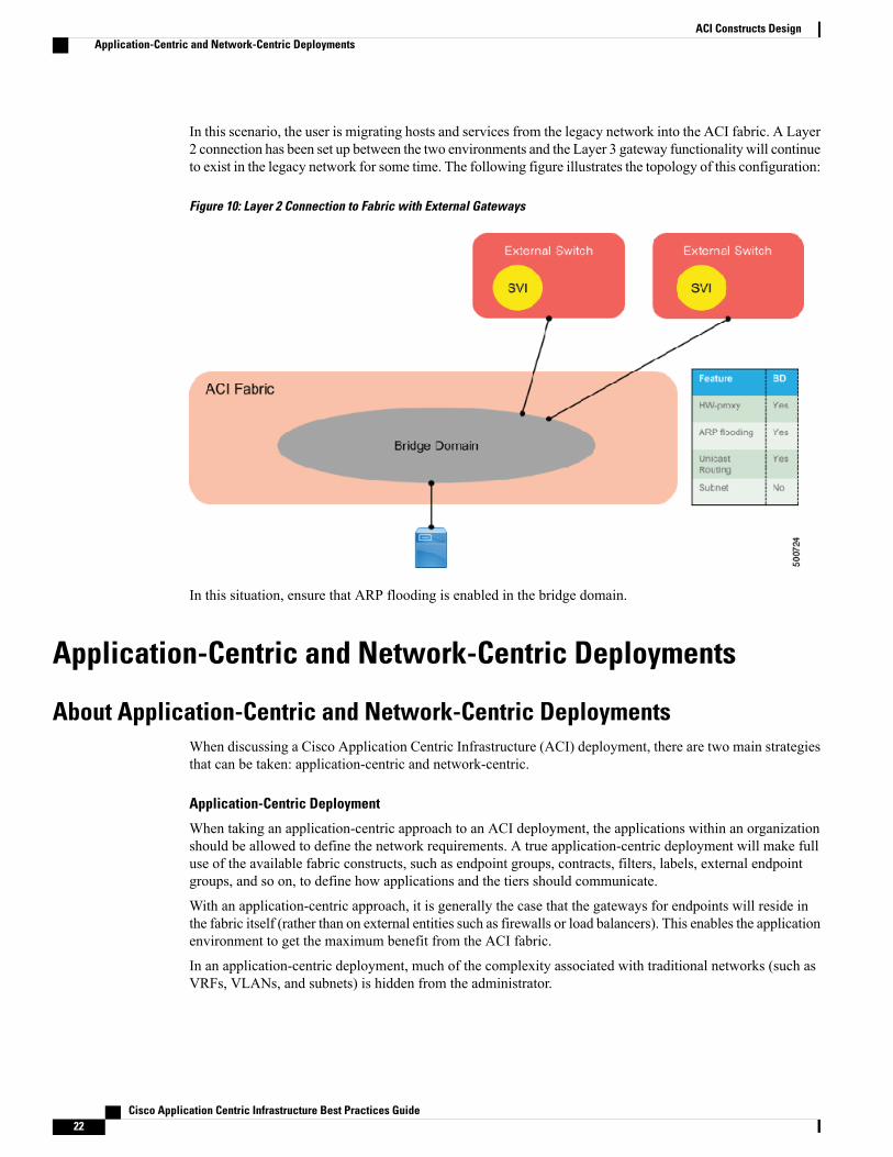
In this scenario, the user is migrating hosts and services from the legacy network into the ACI fabric. A Layer2 connection has been set up between the two environments and the Layer 3 gateway functionality will continueto exist in the legacy network for some time. The following figure illustrates the topology of this configuration:
Figure 10: Layer 2 Connection to Fabric with External Gateways
In this situation, ensure that ARP flooding is enabled in the bridge domain.
Application-Centric and Network-Centric Deployments
About Application-Centric and Network-Centric DeploymentsWhen discussing a Cisco Application Centric Infrastructure (ACI) deployment, there are two main strategiesthat can be taken: application-centric and network-centric.
Application-Centric Deployment
When taking an application-centric approach to an ACI deployment, the applications within an organizationshould be allowed to define the network requirements. A true application-centric deployment will make fulluse of the available fabric constructs, such as endpoint groups, contracts, filters, labels, external endpointgroups, and so on, to define how applications and the tiers should communicate.
With an application-centric approach, it is generally the case that the gateways for endpoints will reside inthe fabric itself (rather than on external entities such as firewalls or load balancers). This enables the applicationenvironment to get the maximum benefit from the ACI fabric.
In an application-centric deployment, much of the complexity associated with traditional networks (such asVRFs, VLANs, and subnets) is hidden from the administrator.
Cisco Application Centric Infrastructure Best Practices Guide22
ACI Constructs DesignApplication-Centric and Network-Centric Deployments
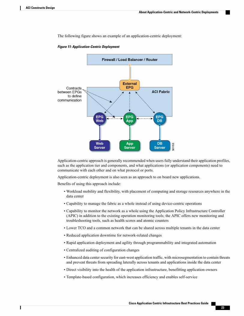
The following figure shows an example of an application-centric deployment:
Figure 11: Application-Centric Deployment
Application-centric approach is generally recommended when users fully understand their application profiles,such as the application tier and components, and what applications (or application components) need tocommunicate with each other and on what protocol or ports.
Application-centric deployment is also seen as an approach to on board new applications.
Benefits of using this approach include:
•Workload mobility and flexibility, with placement of computing and storage resources anywhere in thedata center
• Capability to manage the fabric as a whole instead of using device-centric operations
• Capability to monitor the network as a whole using the Application Policy Infrastructure Controller(APIC) in addition to the existing operation monitoring tools; the APIC offers new monitoring andtroubleshooting tools, such as health scores and atomic counters
• Lower TCO and a common network that can be shared across multiple tenants in the data center
• Reduced application downtime for network-related changes
• Rapid application deployment and agility through programmability and integrated automation
• Centralized auditing of configuration changes
• Enhanced data center security for east-west application traffic, with microsegmentation to contain threatsand prevent threats from spreading laterally across tenants and applications inside the data center
• Direct visibility into the health of the application infrastructure, benefitting application owners
• Template-based configuration, which increases efficiency and enables self-service
Cisco Application Centric Infrastructure Best Practices Guide 23
ACI Constructs DesignAbout Application-Centric and Network-Centric Deployments

Network-Centric Deployment
A network-centric deployment takes the opposite approach to the application-centric deployment in that thetraditional network constructs, such as VLANs and VRFs, are mapped as closely as possible to the newconstructs within the ACI fabric.
As an example, a traditional network deployment might consist of the following tasks:
• Define 2 server VLANs at the access and aggregation layers
• Configure the access ports to map server to VLANs
• Define a VRF at the aggregation layer
• Define an SVI for each VLAN, and map them to the VRF
• Define the HSRP parameters for each SVI
• Apply features such as ACLs to control traffic between server VLANs, and from server VLANs to thecore
The comparable ACI deployment when taking a network-centric approach might be as follows:
• Deploy the fabric
• Create a tenant and VRF
• Define bridge domains for the purposes of external routing entity communication
• Create an external/outside endpoint group to communicate with external networks
• Create two bridge domains and assign a network to each indicating the gateway IP address (such as10.10.10.1/24 and 10.10.11.1/24)
• Define the endpoint groups
• Define a "permit any" contract to allow any to any EPG communication, as a VRF would do in ‘classic’model without ACLs
If external gateways are defined (such as firewalls or load balancers) for endpoints to use, this constitutes anetwork-centric approach. In this scenario, no contracts are required to allow access to the default gatewayfrom endpoints. Although there are still benefits to be had in terms of centralized control, the fabric mightbecome more of a Layer 2 transport in certain situations where the gateways are not inside the fabric.
Cisco Application Centric Infrastructure Best Practices Guide24
ACI Constructs DesignAbout Application-Centric and Network-Centric Deployments
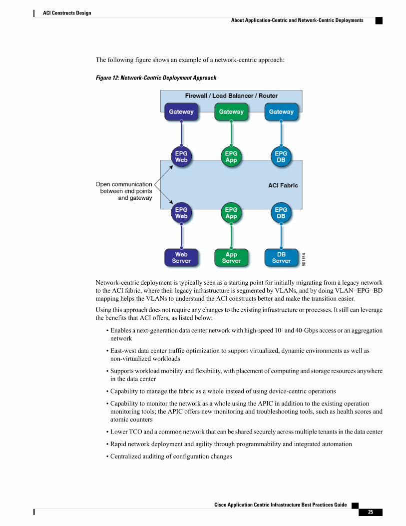
The following figure shows an example of a network-centric approach:
Figure 12: Network-Centric Deployment Approach
Network-centric deployment is typically seen as a starting point for initially migrating from a legacy networkto the ACI fabric, where their legacy infrastructure is segmented by VLANs, and by doing VLAN=EPG=BDmapping helps the VLANs to understand the ACI constructs better and make the transition easier.
Using this approach does not require any changes to the existing infrastructure or processes. It still can leveragethe benefits that ACI offers, as listed below:
• Enables a next-generation data center network with high-speed 10- and 40-Gbps access or an aggregationnetwork
• East-west data center traffic optimization to support virtualized, dynamic environments as well asnon-virtualized workloads
• Supports workloadmobility and flexibility, with placement of computing and storage resources anywherein the data center
• Capability to manage the fabric as a whole instead of using device-centric operations
• Capability to monitor the network as a whole using the APIC in addition to the existing operationmonitoring tools; the APIC offers new monitoring and troubleshooting tools, such as health scores andatomic counters
• Lower TCO and a common network that can be shared securely across multiple tenants in the data center
• Rapid network deployment and agility through programmability and integrated automation
• Centralized auditing of configuration changes
Cisco Application Centric Infrastructure Best Practices Guide 25
ACI Constructs DesignAbout Application-Centric and Network-Centric Deployments
• Direct visibility into the health of the application infrastructure
Layer 2 Extension
About Layer 2 ExtensionWhen extending a Layer 2 domain outside of the Cisco Application Centric Infrastructure (ACI) fabric tosupport migrations from the existing network to a newACI fabric, or to interconnect dual ACI fabrics at Layer2, there are the two methods to extend your Layer 2 domain:
• Extend the endpoint group out of the ACI fabric using endpoint group static path binding
• Extend the bridge domain out of the ACI fabric using an external bridged domain (also known as a Layer2 outside)
When extending the bridge domain, only a single Layer 2 outside can be created per bridge domain.Note
Endpoint group extension is the most popular approach to extend Layer 2 domains, where each individualendpoint group is extended using a dedicated VLAN beyond the fabric. This method is the most commonlyused, as it is easy to deploy and does not require the use of contracts between the inside and outside networks.
However, if you use one bridge domain with multiple endpoint groups, then when you interconnect ACIfabrics in Layer 2, you should not use the endpoint group extension method due to the risk of loops.
Configuration Examples for Layer 2 ExtensionWhen designing a Cisco Application Centric Infrastructure (ACI) environment for dual data centers, onetopology option is to use separate fabrics, one per site, with a Layer 2 interconnection between them. In thisscenario, each fabric is managed by its own Application Policy Infrastructure Controller (APIC) cluster, withno sharing or synchronization of policies between each.
Cisco Application Centric Infrastructure Best Practices Guide26
ACI Constructs DesignLayer 2 Extension

The following figure illustrates interconnecting ACI fabrics at Layer 2:
Figure 13: Interconnect Fabrics at Layer 2 with Multiple Endpoint Groups per Bridge Domain (Scenario Not Recommended)
In this example, multiple endpoint groups are associated with a single bridge domain. In this scenario, youshould not extend each individual endpoint group between fabrics as shown in the figure, as this might resultin loops between the fabrics. Instead, a Layer 2 Outside should be used to extend the entire bridge domainusing a single VLAN, as shown in the following figure:
Figure 14: Interconnect Fabrics at Layer 2 - Multiple Endpoint Groups per Bridge Domain (Recommended Scenario)
Additional References for Layer 2 ExtensionFor more information about Layer 2 extension, see the "ACI Layer 2 Connection to the Outside Network"section of the Connecting Application Centric Infrastructure (ACI) to Outside Layer 2 and 3 Networks whitepaper at the following URL:
http://www.cisco.com/c/en/us/solutions/data-center-virtualization/application-centric-infrastructure/white-paper-listing.html
Cisco Application Centric Infrastructure Best Practices Guide 27
ACI Constructs DesignAdditional References for Layer 2 Extension
Infrastructure VXLAN Tunnel Endpoint Pool
About Infrastructure VXLAN Tunnel Endpoint PoolThe Cisco Application Centric Infrastructure (ACI) fabric is brought up in a cascading manner, starting withthe leaf nodes that are directly attached to the Application Policy Infrastructure Controller (APIC). LLDP andcontrol-plane IS-IS convergence occurs in parallel to this boot process. The ACI fabric uses LLDP- andDHCP-based fabric discovery to automatically discover the fabric switch nodes, assign the infrastructureVXLAN tunnel endpoint (VTEP) addresses, and install the firmware on the switches.
The VTEP pool, which is specified only once during fabric discovery, is the pool of addresses used whilebuilding the fabric. That is, each switch node added to the fabric gets an address. The VTEP pool is used forother infrastructure related extensions, such as extending the infrastructure into a host for Application VirtualSwitch (AVS) integration.
Prerequisites for Infrastructure VXLAN Tunnel Endpoint PoolYou must meet the following prerequisites to use infrastructure VXLAN Tunnel Endpoint Pool (VTEP):
• The Application Policy Infrastructure Controllers (APICs) are clean and have no configuration. Theonly time the VTEP pool gets set for the infrastructure is during the startup script on the APICs.
• The leaf and spine nodes to be added to the fabric are running a Cisco Application Centric Infrastructure(ACI) image and not an NX-OS standalone image.
• The leaf and spine nodes to be added to the fabric are not part of another ACI fabric.
Guidelines and Limitations for Infrastructure VXLAN Tunnel Endpoint PoolThe following guidelines and limitations apply for infrastructure VXLAN Tunnel Endpoint Pool (VTEP):
• The infrastructure VTEP address cannot be changed once the fabric is built around it.
• To change the VTEP pool, the fabric must be rebuilt from scratch. This is a disruptive process and willrequire the configuration to be exported, then imported after the initial fabric steps are completed.
• Generally, the infrastructure subnet stays internal to the fabric. The subnet exists within its own VRFand is rarely exposed beyond that.
• There are a few scenarios, such as Application Virtual Switch (AVS) integration, where this subnet getsexposed outside of the fabric. Due to this, ensure that this subnet does not overlap with another subnetthat is in use within the data center.
•While the minimum supported subnet size is a /22, this is not an ideal pool size and will cause scaleissues while attempting to grow the fabric. Subnet size /22 is only recommended for a small labenvironment.
If subnet size is a concern, a recommended subnet size for the VTEP pool is a /19. Otherwise, the idealsubnet size for the VTEP pool is a /16.
Cisco Application Centric Infrastructure Best Practices Guide28
ACI Constructs DesignInfrastructure VXLAN Tunnel Endpoint Pool
Recommended Configuration Procedure for Infrastructure VXLAN TunnelEndpoint Pool
The Infrastructure VTEP pool only ever gets set on the Application Policy Infrastructure Controller (APIC)during the startup script before the fabric is ever built.
Verifying the Infrastructure VXLAN Tunnel Endpoint PoolThe point at which the infrastructure VTEP pool can be verified is right before accepting the configurationwithin the startup script on the Application Policy Infrastructure Controller (APIC). The APIC asks if theconfiguration is correct, including the VTEP pool address assignment. After you confirm that the configurationis correct, the larger pool gets broken into multiple DHCP pools for various purposes within the fabric andthere is currently no straightforward way to verify the initial pool size after startup script acceptance.
That being said, with the APIC connected to the fabric, the following procedure can be used to observe thepools that the initial TEP pool was carved up into, and subsequently the initial network it is carved from.
Procedure
Use themoquery –c dhcpPool command to view the TEP pool confugration.
Example:Apic1# moquery –c dhcpPool...dn : prov-3/net-[10.0.0.0/16]/pool-7Specifically within the output distinguished name of this class, there is a section that begins with "net-". Inthe example snippet above, the APIC was configured with 10.0.0.0/16 as its TEP pool within the setup scriptof the APIC.
Configuration Examples for Infrastructure VXLAN Tunnel Endpoint PoolThe default configuration is 10.0.0.0/16. The configuration is only set once during the startup script on theApplication Policy Infrastructure Controller (APIC).
Additional References for Infrastructure VXLAN Tunnel Endpoint PoolFor more information on setting up the Application Policy Infrastructure Controller (APIC), see the CiscoAPIC Getting Started Guide at the following URL:
http://www.cisco.com/c/en/us/support/cloud-systems-management/application-policy-infrastructure-controller-apic/tsd-products-support-series-home.html
Cisco Application Centric Infrastructure Best Practices Guide 29
ACI Constructs DesignRecommended Configuration Procedure for Infrastructure VXLAN Tunnel Endpoint Pool
Virtual Routing and Forwarding Instances
About Virtual Routing and Forwarding InstancesA virtual routing and forwarding (VRF) instance, also called a context, represents an application policy domainand Layer 3 forwarding. A tenant can have one or more VRF instances, and a single VRF instance can haveone or more bridge domains. A VRF instance in Cisco Application Centric Infrastructure (ACI) is equivalentto a VRF instance in a traditional network.
Guidelines and Limitations for Virtual Routing and Forwarding InstancesThe following guidelines and limitations apply for virtual routing and forwarding (VRF) instances:
•Within a single VRF instance, IP addresses must be unique. Between different VRF instances, you canhave overlapping IP addresses.
• If shared services is used between VRF instances or tenants, make sure there are no overlapping IPaddresses.
• Any VRF instances that are created in common tenant will be seen in other user-configured tenants.
• VRF supports enforced mode or unenforced mode. By default, a VRF instance is in enforced mode,which means all endpoint groups within the sameVRF instance cannot communicate to each other unlessthere is a contract in place.
• Switching from enforced to unenforced mode (or vice versa) is disruptive.
Additional References for Virtual Routing and Forwarding InstancesFor more information about virtual routing and forwarding (VRF) instances, see theCisco Application CentricInfrastructure Fundamentals Guide at the following URL:
http://www.cisco.com/c/en/us/support/cloud-systems-management/application-policy-infrastructure-controller-apic/tsd-products-support-series-home.html
Stretched Fabric
About Stretched FabricThe stretched fabric allows users to manage multiple datacenter sites as a single fabric by using the sameApplication Policy Infrastructure Controller (APIC) controller cluster. The stretched Cisco Application Centric
Cisco Application Centric Infrastructure Best Practices Guide30
ACI Constructs DesignVirtual Routing and Forwarding Instances
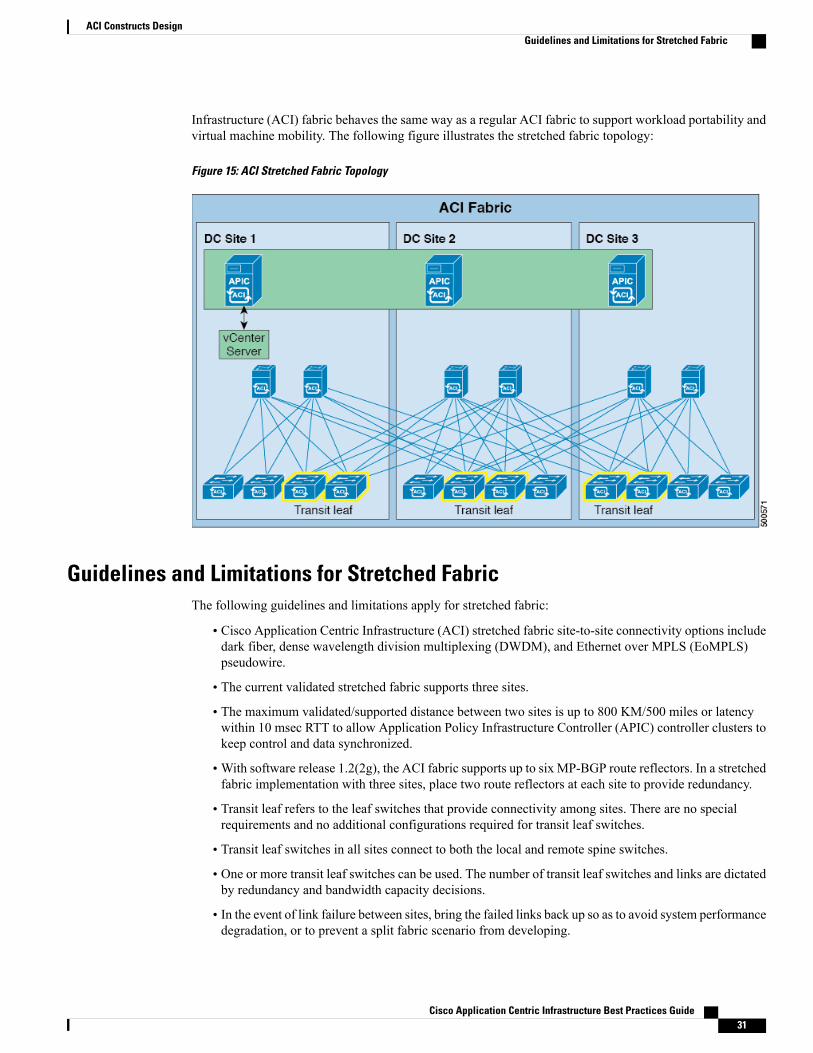
Infrastructure (ACI) fabric behaves the same way as a regular ACI fabric to support workload portability andvirtual machine mobility. The following figure illustrates the stretched fabric topology:
Figure 15: ACI Stretched Fabric Topology
Guidelines and Limitations for Stretched FabricThe following guidelines and limitations apply for stretched fabric:
• Cisco Application Centric Infrastructure (ACI) stretched fabric site-to-site connectivity options includedark fiber, dense wavelength division multiplexing (DWDM), and Ethernet over MPLS (EoMPLS)pseudowire.
• The current validated stretched fabric supports three sites.
• The maximum validated/supported distance between two sites is up to 800 KM/500 miles or latencywithin 10 msec RTT to allow Application Policy Infrastructure Controller (APIC) controller clusters tokeep control and data synchronized.
•With software release 1.2(2g), the ACI fabric supports up to six MP-BGP route reflectors. In a stretchedfabric implementation with three sites, place two route reflectors at each site to provide redundancy.
• Transit leaf refers to the leaf switches that provide connectivity among sites. There are no specialrequirements and no additional configurations required for transit leaf switches.
• Transit leaf switches in all sites connect to both the local and remote spine switches.
• One or more transit leaf switches can be used. The number of transit leaf switches and links are dictatedby redundancy and bandwidth capacity decisions.
• In the event of link failure between sites, bring the failed links back up so as to avoid system performancedegradation, or to prevent a split fabric scenario from developing.
Cisco Application Centric Infrastructure Best Practices Guide 31
ACI Constructs DesignGuidelines and Limitations for Stretched Fabric

• Bridge domains/IP subnets can be stretched between sites
Additional References for Stretched FabricFor more information about stretched fabric, including failure scenarios and more operational guidelines, seethe ACI Stretched Fabric Design knowledge base article at the following URL:
http://www.cisco.com/c/en/us/support/cloud-systems-management/application-policy-infrastructure-controller-apic/tsd-products-support-series-home.html
Access Policies
About Access PoliciesThe Fabric tab in the Cisco Application Policy Infrastructure Controller (APIC) GUI is used to configuresystem-level features including, but not limited to, device discovery and inventory management, diagnostictools, domain configuration, and switch and port behavior. The fabric pane is split into three sections: Inventory,Fabric Policies, and Access Policies. Understanding how fabric and access policies configure the fabric iskey for maintaining these policies for the purposes of internal connections between fabric leaf nodes,connections to external entities such as servers, networking equipment, and storage arrays.
This section lists guidelines and provides common configuration examples for key objects in the Fabric >Access Policies view. The Access Policies view is split into folders separating out different types of policiesand objects that affect fabric behavior. For example, the Interface Policies folder is where port behavior isconfigured such as port speed and the controls for specifying whether or not to run protocols, such as LACP,on switch interfaces. Domains and AEPs are also created in the Access Policies view. The fabric accesspolicies provide the fabric with the base configuration of the access ports on the leaf switches. For moreinformation, see Additional References for Access Policies, on page 37.
Guidelines and Limitations for Access PoliciesCisco has established several best practices for fabric configuration. These are not requirements, and mightnot work for all environments or applications, but might help simplify day-to-day operation of the CiscoApplication Centric Infrastructure (ACI) fabric.
This section contains basic guidelines for access policies.
General Guidelines
• Policies should be created once and reused when connecting new devices to the fabric. Maximizing thereusability of policy and objects makes day-to-day operations exponentially faster and easier to makelarge-scale changes.
The usage of these policies can be viewed by clicking the Show Usage button in theApplication Policy Infrastructure Controller (APIC) GUI. Use this to determine whatobjects are using a certain policy to understand the impact when making changes.
Note
Cisco Application Centric Infrastructure Best Practices Guide32
ACI Constructs DesignAdditional References for Stretched Fabric

• Avoid using the Basic GUI orQuick Startwizards, as these may create many automatic configurationsthat are not intuitive during troubleshooting.
Interface Policy Guidelines
• Do not use the default setting for interface policies, if possible.
• Reuse policies whenever possible. For example, create new separate interface policies for LACP active,passive, and mac-pinning; for 1-GE port speed and 10-GE port speed; and for CDP and LLDP policies.
•When naming interface policies, use names that clearly describe the setting. For example, a policy thatenables LACP in mode active could be called "LACP-Active". There are many default policies out ofthe box. However, it can be hard to remember what all the defaults are, which is why policies should beclearly named to avoid making a mistake when adding new devices to the fabric.
Domain Guidelines
• Build one physical domain per tenant for bare metal servers or servers without hypervisor integrationrequiring similar treatment.
• Build one external routed/bridged domain per tenant for external connectivity.
• For VMM domains, if both DVS and AVS is in use, create a separate VMM domain to support eachenvironment.
• For large deployments where domains (physical/VMM/etc) need to be leveraged across multiple tenants,a single physical domain or VMMdomain can be created and associated with all leaf ports where servicesare connected.
AEP Guidelines
• Multiple domains can be associated to a single AEP for simplicity. There are some cases where multipleAEPs may need to be configured to enable the infrastructure VLAN, such as overlapping VLAN pools,or to limit the scope of the presence of VLANs across the fabric.
• Another scenario in which multiple AEPs should be utilized is when making an association to VMMdomains. The AAEP also contains relationships to the vSwitch policies, which are then pushed to thevCenter VDS or AVS. If there are multiple VMM domains deployed with differing vSwitch policies,multiple AAEPs should be created to account for the various potential vSwitch policy combinations.
•When utilizing an AVS for VMM, HyperV, SCVMM, or OpenStack OpFlex integration, the AAEP iswhere the option to enable infra vlan is selected. For the most part, we do not want to extend this VLANoutside of the fabric aside for when performing this integration. For that purpose, it will be beneficialto create an AEP specific to the AVS VMM Domain if being utilized.
Configuration Examples for Access PoliciesThis section describes two common methods for deploying your leaf switches, explains how to create andassociate switch and interface profiles, and shows how to create a port channel policy and a vPC domain.
Creating Access Policies for SwitchesThe following describes two common methods for deploying your leaf switches:
Cisco Application Centric Infrastructure Best Practices Guide 33
ACI Constructs DesignConfiguration Examples for Access Policies
• Create a switch profile for each leaf switch individually regardless of vPC definition existence.
• Create a switch profile for each leaf switch individually. Additionally, create a switch profile for eachvPC pair (if using vPC).
For both methods, you also create an interface profile for each switch profile. Each interface profile will groupall the interface selectors associated to that specific switch. In the event of adding or deleting new/existingports, changes will only be made under interface profiles, as those interface profiles are already associated tothe corresponding switch profiles.
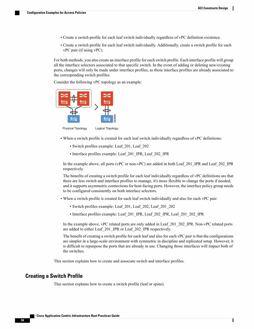
Consider the following vPC topology as an example:
•When a switch profile is created for each leaf switch individually regardless of vPC definitions:
• Switch profiles example: Leaf_201, Leaf_202
• Interface profiles example: Leaf_201_IPR, Leaf_202_IPR
In the example above, all ports (vPC or non-vPC) are added in both Leaf_201_IPR and Leaf_202_IPRrespectively.
The benefits of creating a switch profile for each leaf individually regardless of vPC definitions are thatthere are less switch and interface profiles to manage, it's more flexible to change the ports if needed,and it supports asymmetric connections for host-facing ports. However, the interface policy group needsto be configured consistently on both interface selectors.
•When a switch profile is created for each leaf switch individually and also for each vPC pair:
• Switch profiles example: Leaf_201, Leaf_202, Leaf_201_202
• Interface profiles example: Leaf_201_IPR, Leaf_202_IPR, Leaf_201_202_IPR
In the example above, vPC related ports are only added in Leaf_201_202_IPR. Non-vPC related portsare added to either Leaf_201_IPR or Leaf_202_IPR respectively.
The benefit of creating a switch profile for each leaf and also for each vPC pair is that the configurationsare simpler in a large-scale environment with symmetric in discipline and replicated setup. However, itis difficult to repurpose the ports that are already in use. Changing those interfaces will impact both ofthe switches.
This section explains how to create and associate switch and interface profiles.
Creating a Switch ProfileThis section explains how to create a switch profile (leaf or spine).
Cisco Application Centric Infrastructure Best Practices Guide34
ACI Constructs DesignConfiguration Examples for Access Policies
Before You Begin
You must have a configured leaf or spine switch.
Procedure
Step 1 From the Fabric tab, click Access Policies.Step 2 In the Navigation pane, choose Switch Policies > Profiles.
The Leaf Profile and Spine Profile options appear in the Navigation pane.Step 3 Choose Leaf Profile or Spine Profile.Step 4 In theWork pane, click Actions and choose the option to create a profile.
A dialog appears. When creating a leaf profile, theCreate Leaf Profile dialog appears. When creating a spineprofile, the Create Spine Profile dialog appears.
Step 5 Enter the appropriate values in the fields of the dialog.For an explanation of a field, click the 'i' icon on the top-right corner of the dialog box to display thehelp file.
Note
Step 6 When done, click Finish.
Creating an Interface ProfileThis section explains how to create a switch profile (leaf or spine).
Before You Begin
You must have a configured leaf or spine switch.
Procedure
Step 1 From the Fabric tab, click Access Policies.Step 2 In the Navigation pane, choose Interface Policies > Profiles.
The Leaf Profile and Spine Profile options appear in the Navigation pane.Step 3 Choose Leaf Profile or Spine Profile.Step 4 In theWork pane, click Actions and choose the option to create a profile.
A dialog appears. When creating a leaf profile, the Create Leaf Interface Profile dialog appears. Whencreating a spine profile, the Create Spine Interface Profile dialog appears.
Step 5 Enter the appropriate values in the fields of the dialog.For an explanation of a field, click the 'i' icon on the top-right corner of the dialog box to display thehelp file.
Note
Step 6 When done, click Submit.
Cisco Application Centric Infrastructure Best Practices Guide 35
ACI Constructs DesignConfiguration Examples for Access Policies
Associating Switch and Interface Profiles
Before You Begin
• You have created a switch (leaf or spine) profile.
• You have created an interface (leaf or spine) profile.
This section explains how to associate switch profiles with interface profiles.
Procedure
Step 1 From the Fabric tab, click Access Policies.Step 2 In the Navigation pane, click Switch Policies > Profiles.
The Leaf Profile and Spine Profile options appear in the Navigation pane.Step 3 Click the Leaf Profile or Spine Profile drop-down arrow.
Your profile icons appear in the drop-down list in the Navigation pane.Step 4 In the Navigation pane, click on a profile icon to choose a switch profile.
Your profile details appear in theWork pane.Step 5 From the Associated Interface Selector Profiles table in theWork pane, click the + (plus) symbol.
The Create Interface Profile dialog appears.Step 6 Click the Interface Select Profile drop-down arrow and choose an interface profile to associate with your
switch profile.Step 7 When done, click Submit.
Creating a Port Channel PolicyThis section explains how to create a port channel policy.
Procedure
Step 1 From the Fabric tab, click Access Policies.Step 2 In the Navigation pane, choose Interface Policies > Policies > Port Channel.Step 3 From theWork pane, click Actions > Create Port Channel Policy.
The Specify Port Channel Policy dialog appears.Step 4 Enter the appropriate values in the Specify Port Channel Policy dialog fields.
Note • For an explanation of a field, click the 'i' icon on the top-right corner of the dialog box to displaythe help file.
• The LACP Active option for theMode field sets a port to the suspended state if it does notreceive an LACP PDU from the peer. Although this feature helps in preventing loops createddue to misconfigurations, in some cases, the feature can cause servers to fail to boot up becausethey require LACP to logically bring up the port. This is the use case that you typically wouldsee with PXE boot. As a workaround, you click the checked Suspend-Individual Port checkbox in theControl options to uncheck/disable the option and put a port into an individual state.
Cisco Application Centric Infrastructure Best Practices Guide36
ACI Constructs DesignConfiguration Examples for Access Policies
Step 5 When finished, click Submit.
Creating a vPC DomainFor server active/active deployments, vPC can be used to provide larger uplink bandwidth and fasterconvergence upon link or switch failures.
Unlike traditional vPC design, there is no requirement for setting up either a vPC peer-link or vPCpeer-keepalive in the Cisco Application Centric Infrastructure (ACI) fabric. The fabric itself serves as thepeer-link. The rich interconnectivity between spine switches and leaf switches makes it very unlikely that allthe redundant paths between vPC peers fail at the same time. Hence, if the peer switch becomes unreachable,it is assumed to have crashed. The slave switch does not bring down vPC links.
For more information, see the Operating Cisco Application Centric Infrastructure document at the followingURL: http://www.cisco.com/c/en/us/support/cloud-systems-management/application-policy-infrastructure-controller-apic/tsd-products-support-series-home.html.
Procedure
Step 1 From the Fabric tab, click Access Policies.Step 2 In the Navigation pane, click Switch Policies > Policies > Virtual Port Channel default.
The Virtual Port Channel Security Policy - Virtual Port Channel default window appears.Step 3 Enter the appropriate values in the fields of theVirtual Port Channel Security Policy - Virtual Port Channel
default window.For an explanation of a field, click the 'i' icon on the top-right corner of the dialog box to display thehelp file.
Note
Step 4 When finished, click Submit.
Additional References for Access PoliciesFor more information, see Operating Cisco Application Centric Infrastructure document at the followingURL: http://www.cisco.com/c/en/us/support/cloud-systems-management/application-policy-infrastructure-controller-apic/tsd-products-support-series-home.html.
Mis-Cabling Protocol
About the Mis-Cabling ProtocolUnlike traditional networks, the Cisco Application Centric Infrastructure (ACI) fabric does not participate inthe Spanning Tree Protocol (STP) and does not generate bridge protocol data units (BPDUs). BPDUs areinstead transparently forwarded through the fabric between ports mapped to the same endpoint group. Therefore,Cisco ACI relies to a certain degree on the loop prevention capabilities of external devices.
Cisco Application Centric Infrastructure Best Practices Guide 37
ACI Constructs DesignAdditional References for Access Policies

Some scenarios, such as the accidental cabling of two leaf ports together, are handled directly using LLDP inthe fabric. However, there are some situations where an additional level of protection is necessary; in thosecases, enabling the Mis-Cabling Protocol (MCP) can help.
Consider the example in the following figure:
Figure 16: VLAN Misconfiguration
In this example, two endpoint groups are configured on the Cisco ACI fabric, both associated with the samebridge domain. An external switch has one port connected to each of the endpoint groups. In this example, amisconfiguration has occurred whereby the external switch is allowing VLAN 10 on port 1/20; however, theendpoint group associated with port 1/10 on leaf 102 is configured for VLAN 11. In this case, port 1/10 onleaf 102 will not be able to receive BPDUs for VLAN 10. As a result, the spanning tree cannot detect the loopand all ports will be forwarding.
The MCP protocol, if enabled, provides additional protection against this type of misconfiguration. MCP isa lightweight protocol designed to protect against loops that cannot be discovered by either STP or LLDP.You should enable MCP on all ports facing external switches or similar devices.
Per-VLANMCP will only run on 256 VLANs per interface. If there are more than 256 VLANs, then thefirst numerical 256 VLANs are chosen.
Note
Configuration Examples for the Mis-Cabling ProtocolTo enable the Mis-Cabling Protocol (MCP) in the fabric, you must enable MCP globally through the globalpolicies and also on individual ports or port channels through the interface policy group configuration.
Procedure
Step 1 On the menu bar, choose Fabric > Access Policies.Step 2 In the Navigation pane, choose Global Policies >MCP Insurance Policy Default.Step 3 In theWork pane, for the Admin State buttons, choose Enabled.Step 4 For the remaining properties, change the values as desired.
Cisco Application Centric Infrastructure Best Practices Guide38
ACI Constructs DesignMis-Cabling Protocol
• Key and Confirm Key—A key that uniquely identifies MCP packets within the fabric.
• Initial Delay (sec)—The delay time in seconds before MCP begins taking action.
• Loop Detect Multiplication Factor—Denotes the number of continuous packets a port must receivebefore declaring a loop.
Step 5 Enable MCP on the interface level, which is done when you create an access port policy group. On the menubar, choose Fabric > Access Policies.
Step 6 In the Navigation pane, choose Interface Policies > Policy Groups.Step 7 In theWork pane, choose Actions > Create Access Policy Group.Step 8 In the Create Access Policy Group dialog box, in theMCP Policy drop-down list, chooseMCP-Enabled.Step 9 Fill out the remaining fields as necessary.Step 10 Click Submit.
Additional References for the Mis-Cabling ProtocolFor more information about theMis-Cabling Protocol (MCP), see the section about loop detection in theCiscoApplication Centric Infrastructure Fundamentals Guide at the following URL:
http://www.cisco.com/c/en/us/support/cloud-systems-management/application-policy-infrastructure-controller-apic/tsd-products-support-series-home.html
Port Tracking
About Port TrackingPort tracking policies are used to monitor the status of links between leaf switches and spine switches. Whenan enabled port tracking policy is triggered, the leaf switches take down all access interfaces on the switchthat have endpoint groups deployed on them.
Port tracking addresses a scenario in which a leaf node might lose connectivity to the spine node and wherehosts connected to the affected leaf node in an active/standby manner might not be aware of the failure for aperiod of time. The following figure illustrates this scenario:
Cisco Application Centric Infrastructure Best Practices Guide 39
ACI Constructs DesignPort Tracking
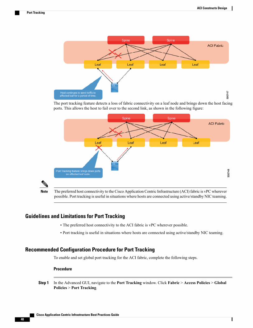
The port tracking feature detects a loss of fabric connectivity on a leaf node and brings down the host facingports. This allows the host to fail over to the second link, as shown in the following figure:
The preferred host connectivity to the Cisco Application Centric Infrastructure (ACI) fabric is vPCwhereverpossible. Port tracking is useful in situations where hosts are connected using active/standbyNIC teaming.
Note
Guidelines and Limitations for Port Tracking• The preferred host connectivity to the ACI fabric is vPC wherever possible.
• Port tracking is useful in situations where hosts are connected using active/standby NIC teaming.
Recommended Configuration Procedure for Port TrackingTo enable and set global port tracking for the ACI fabric, complete the following steps.
Procedure
Step 1 In the Advanced GUI, navigate to the Port Tracking window. Click Fabric > Access Policies > GlobalPolicies > Port Tracking.
Cisco Application Centric Infrastructure Best Practices Guide40
ACI Constructs DesignPort Tracking

Step 2 In the Port Tracking window, locate the Port Tracking state field and click on.Step 3 Set the Delay restore timer parameter.
This timer controls the number of seconds the fabric waits before bringing host ports up after the leaf spinelinks re-converge.
Step 4 Set the Number of Active Spine Links parameter.This value specifies how low the number of active links drop to before Port Tracking is triggered. The value'0' configures Port Tracking to be triggered after the number of active links to the spine drops to zero.
Step 5 Click Submit.
VLAN Pools
About VLAN PoolsWithin Cisco Application Centric Infrastructure (ACI), there is the concept of access policies, which are agroup of objects that define how traffic can get access into the fabric. Access policy definition matters whenan EPG is created for use. For example, an EPG that has a static path (for example, node 101, int eth1/10,trunked with VLAN 10) without access policies is essentially telling the EPG to use a set of policies to whichit does not have access. At this point, you will see faults indicating path issues. The access policies andsubsequent domain-to-EPG association tell this EPG that it now has access to a subset of nodes, interfaces,and VLANs that it can now use in path definitions.
VLAN pools are just one piece of the complete access policies definition. A VLAN pool is a container thatis comprised of encap blocks, which contain the actual VLAN definitions.
Prerequisites for VLAN Pools• A Cisco ACI fabric that has been initialized.
• An understanding of access policies and their purpose. For information on access policies, see AboutAccess Policies, on page 32
Guidelines and Limitations for VLAN Pools• VLAN pools containing overlapping encap block definitions should not be associated to the sameAAEP(and subsequently the same leaf nodes). This can cause issues with BPDU forwarding through the fabricif the domains associated to an EPG have overlapping VLAN block definitions.
• VLAN pools with an allocation mode of Dynamic are typically used for VMM integration deployments.VMM integration generally does not require explicit VLAN assignment, so a dynamic pool allows thesystem to pull free resources as needed.
• VLAN pools with an allocationmode is Static are typical for the majority of other deployment scenariosincluding static paths, L2Out and L3Out out definitions.
• A dynamic VLAN pool can have a static encap block defined within it. This is generally only done forthe specific case of utilizing the "pre-provision" resolution immediacy.
Cisco Application Centric Infrastructure Best Practices Guide 41
ACI Constructs DesignVLAN Pools

• A static VLAN pool cannot have a dynamic encap block. This will be rejected by the Application PolicyInfrastructure Controller (APIC), as there are no features that utilize this configuration.
Recommended Configuration Procedures for VLAN PoolsSee Guidelines and Limitations for VLAN Pools.
Configuration Examples for VLAN PoolsFor configuration examples of VLAN pools, please see the Creating Domains, Attach Entity Profiles, andVLANs to Deploy an EPG on a Specific Port at the following URL: http://www.cisco.com/c/en/us/support/cloud-systems-management/ application-policy-infrastructure-controller-apic/tsd-products-support-series-home.html
Additional References for VLAN PoolsFor additional information on access policies, including VLAN pools, see the Cisco Application CentricInfrastructure Fundamentals document at the following URL: http://www.cisco.com/c/en/us/support/cloud-systems-management/ application-policy-infrastructure-controller-apic/tsd-products-support-series-home.html
Managed Object Naming Convention
About the Managed Object Naming ConventionCisco Application Centric Infrastructure (ACI) is based upon the managed object (MO) model, where eachobject requires a name. A clear and consistent naming convention is therefore essential to aid manageabilityand troubleshooting.
Any change in naming convention for any MO such as profiles or policies requires disruption. It is highlyrecommended to plan ahead and define the policy naming convention before deploying the ACI fabric toensure that all policies are named consistently.
Cisco Application Centric Infrastructure Best Practices Guide42
ACI Constructs DesignManaged Object Naming Convention