(ACI 304R_89) - Guide for Measuring, Mixing, Transporting & Placing Concrete
49
This document has been approved for use by agen- cies of the Department of Defense and for listing in the DoD Index of Specifications and Standards. ACI 304R-89 Guide for Measuring, Mixing, Transporting, and Placing Concrete (Reapproved 1997) Reported by ACI Committee 304 James L. Cope,* chairman Raymond A. Ayres* Joseph C. Carson Thomas R. Clapp Wayne J. Costa* Robert M. Eshbach* J. R. Florey Donald E. Graham* Terence C. Holland* Stanley H. Lee* Robert A. Kelsey Kurt R. Melby* Gordon M. Kidd Richard W. Narva John C. King* Leo P. Nicholson William C. Krell* James S. Pierce* Bruce A. Lamberton William J. Sim* This guide presents information on the handling, measuring, and batching of all the materials used in making normal weight, light- weight structural and heavyweight concrete. It covers both weight and volumetric measuring, mixing in central mix plants and truck mixers and concrete placing using buckets, buggies, pumps and conveyors. Underwater concrete placing and preplaced aggregate concrete are also covered. The guide outlines procedures for ob- taining good quality concrete in completed structures. Keywords: absorption; admixtures; aggregate gradation; aggregates; aggre- gate size; air entrainment; batching; bleeding (concrete); cement content; ce- ments; chutes; coarse aggregates; concrete construction; concretes; consol- idation; construction joints; conveying; conveyors; curing; density (mass/ volume); falsework; fine aggregates; fineness modulus; formwork (construc- tion); grout; grouting; heat of hydration; heavyweight aggregates; laitance; lightweight aggregate concretes; lightweight aggregates; mass concrete; mate- rials handling; mixers; mixing; mixing time; mix proportioning; moisture content; placing; pozzolans; preplaced aggregate concrete; pumped concrete; quality control; ready-mixed concrete; retempering; segregation; slipform construction; stockpiling; temperature; transit mixers, tremie concrete; un- derwater construction; vibration; water; water-cement ratio; workability. CONTENTS Chapter 1 - Introduction, page 304R-2 1.1-Scope 1.2-Objective 1.3-Other considerations Jack H. Skinner, III James H. Sprouse Paul R. Stodola* William X. Sypher R. E. Tobin* Francis C.* Wilson Chapter 2 - Control, handling, and storage of materials, page 304R-3 2.1-General considerations 2.2-Aggregates 2.3-Cement Chapter 3 - Measurement and batching, page 304R-6 3.1-General requirements 3.2-Bins and weigh hatchers 3.3-Plant type 3.4-Cementitious materials 3.5-Water measurement 3.6-Measurement of admixtures 3.7-Measurement of materials for small jobs 3.8-Other considerations Chapter 4 - Mixing and transporting, page 304R-11 4.1-General requirements 4.2-Mixing equipment 4.3-Central mixed concrete 4.4-Truck mixed concrete 4.5-Charging and mixing 4.6-Mix temperature 4.7-Discharging 4.8-Mixer performance 4.9-Maintenance 4.10-General considerations for transporting concrete I ACI Committee Reports, Guides, Standard Practices, and Commen- taries are intended for guidance in designing, planning, executing, or I inspecting construction and in preparing specifications. Reference to these documents shall not be made in the Project Documents. If items found in these documents are desired to be a part of the Project Docu- ments, they should be phrased in mandatory language and incorpo- rated into the Project Documents. *Member of the task group which prepared this report. Copyright © 1989, American Concrete Institute. All rights reserved including rights of reproduction and use in any form or by any means, including the making of copies by any photo process, or by any electronic or mechanical device, unless permission in writing is obtained from the copyright proprietors.
-
Upload
pham-hong-minh -
Category
Documents
-
view
176 -
download
34
description
(ACI 304R_89) - Guide for Measuring, Mixing, Transporting & Placing Concrete
Transcript of (ACI 304R_89) - Guide for Measuring, Mixing, Transporting & Placing Concrete
This document has been approved for use by agen-cies of the Department of Defense and for listing inthe DoD Index of Specifications and Standards.
ACI 304R-89
Guide for Measuring, Mixing,Transporting, and Placing Concrete (Reapproved 1997)
Reported by ACI Committee 304
James L. Cope,* chairman
Raymond A. Ayres*Joseph C. CarsonThomas R. ClappWayne J. Costa*Robert M. Eshbach*J. R. FloreyDonald E. Graham*
Terence C. Holland* Stanley H. Lee*Robert A. Kelsey Kurt R. Melby*Gordon M. Kidd Richard W. NarvaJohn C. King* Leo P. NicholsonWilliam C. Krell* James S. Pierce*Bruce A. Lamberton William J. Sim*
This guide presents information on the handling, measuring, andbatching of all the materials used in making normal weight, light-weight structural and heavyweight concrete. It covers both weightand volumetric measuring, mixing in central mix plants and truckmixers and concrete placing using buckets, buggies, pumps andconveyors. Underwater concrete placing and preplaced aggregateconcrete are also covered. The guide outlines procedures for ob-taining good quality concrete in completed structures.
Keywords: absorption; admixtures; aggregate gradation; aggregates; aggre-gate size; air entrainment; batching; bleeding (concrete); cement content; ce-ments; chutes; coarse aggregates; concrete construction; concretes; consol-idation; construction joints; conveying; conveyors; curing; density (mass/volume); falsework; fine aggregates; fineness modulus; formwork (construc-tion); grout; grouting; heat of hydration; heavyweight aggregates; laitance;lightweight aggregate concretes; lightweight aggregates; mass concrete; mate-rials handling; mixers; mixing; mixing time; mix proportioning; moisturecontent; placing; pozzolans; preplaced aggregate concrete; pumped concrete;quality control; ready-mixed concrete; retempering; segregation; slipformconstruction; stockpiling; temperature; transit mixers, tremie concrete; un-derwater construction; vibration; water; water-cement ratio; workability.
CONTENTS
Jack H. Skinner, IIIJames H. SprousePaul R. Stodola*William X. SypherR. E. Tobin*Francis C.* Wilson
Chapter 1 - Introduction, page 304R-2
1.1-Scope1.2-Objective1.3-Other considerations
I ACI Committee Reports, Guides, Standard Practices, and Commen-taries are intended for guidance in designing, planning, executing, or Iinspecting construction and in preparing specifications. Reference tothese documents shall not be made in the Project Documents. If itemsfound in these documents are desired to be a part of the Project Docu-ments, they should be phrased in mandatory language and incorpo-rated into the Project Documents.
Chapter 2 - Control, handling, and storage ofmaterials, page 304R-32.1-General considerations2.2-Aggregates2.3-Cement
Chapter 3 - Measurement and batching,page 304R-63.1-General requirements3.2-Bins and weigh hatchers3.3-Plant type3.4-Cementitious materials3.5-Water measurement3.6-Measurement of admixtures3.7-Measurement of materials for small jobs3.8-Other considerations
Chapter 4 - Mixing and transporting,page 304R-114.1-General requirements4.2-Mixing equipment4.3-Central mixed concrete4.4-Truck mixed concrete4.5-Charging and mixing4.6-Mix temperature4.7-Discharging4.8-Mixer performance4.9-Maintenance4.10-General considerations for transporting concrete
*Member of the task group which prepared this report.Copyright © 1989, American Concrete Institute.All rights reserved including rights of reproduction and use in any form or
by any means, including the making of copies by any photo process, or by anyelectronic or mechanical device, unless permission in writing is obtained fromthe copyright proprietors.
304R-2 MANUAL OF CONCRETE PRACTICE
Chapter 5-Placing concrete, page 304R-14
5.1-General considerations5.2-Planning5.3-Reinforcement and embedded items5.4-Placing
Chapter 6-Forms, joint preparation, andfinishing, page 304R-216.l-Forms6.2-Joint preparation6.3-Finishing unformed surfaces
Chapter 7-Preplaced aggregate structural andmass concrete, page 304R-237.1-General considerations7.2-Materials7.3-Grout mix proportioning7.4-Temperature control7.5-Forms7.6-Grout pipe systems7.7-Coarse aggregate placement7.8-Grout mixing and pumping7.9-Joint construction7.10-Finishing7.11-Quality control
Chapter 8-Concrete placed under water,page 304R-288.l-General considerations8.2-Materials8.3-Mixture proportioning8.4-Concrete production and testing8.5-Tremie equipment and placement procedure8.6-Direct pumping8.7-Concrete characteristics8.8-Precautions8.9-Special applications8.10-New developments
Chapter 9-Pumping concrete, page 304R-32
9.1-General considerations9.2-Pumping equipment9.3-Pipelines and accessories9.4-Proportioning pumpable concrete9.5-Field practices9.6-Field control
Chapter 10-Conveying concrete, page 304R-3710.1-General considerations10.2-Conveyor requirements10.3-Conveyor types and functions10.4-Conveyor charging10.5-Discharge control10.6-Maintenance
Chapter 11-Heavyweight and radiation shieldingconcrete, page 304R-41
11.1-General considerations11.2-Materials11.3-Concrete characteristics11.4-Mixing equipment11.5-Formwork11.6-Placement11.7-Quality control
Chapter 12-Lightweight concrete, page 304R-44
12.1-General considerations12.2-Measuring and batching12.3-Mixing12.4-Job controls
Chapter 13-References, page 304R-4713.1-Recommended references13.2-Cited references
CHAPTER 1 -INTRODUCTION
1.1-Scope
This guide outlines procedures for obtaining goodresults in measuring and mixing ingredients for con-crete, transporting it to the site and placing it. Thefirst six chapters are general in nature and have broadapplication to all types of projects and concrete. Thefollowing, specialized chapters, deal with preplacedaggregate concrete, underwater placing, pumping,and conveying on belts. The concluding chaptersdeal with heavyweight, radiation shielding a n dlightweight concrete.
1.2-Objective
In preparing this guide, the committee followedthis philosophy.
1. Progress in improvement of concrete construc-tion will be better served by the presentation of highstandards rather than “common practices.”
2. In many cases, if not most, practices resulting inthe production and placement of high quality con-crete can be performed as economically as those re-sulting in poor concrete. Many of the practicesrecommended in this document improve concreteuniformity as well as quality so that effort and in-vestment are rewarded by a smoother operation andhigher production rates, both of which offset poten-tial additional cost.
3. It is assumed that anyone planning to use thisguide will have a basic knowledge of the generalpractices involved in concrete work. If more specificinformation on measuring, mixing, transporting, andplacing concrete is desired, the reader should refer tothe list of references given at the end of this docu-ment, and particularly to References 2 and 6 andASTM C 94, ACI 311 and 318 and EM 1110-2-2000.Committee 304 generally agrees with the informationgiven in these references although some exceptionsin emphasis and detail may be noted, To portraymore clearly certain principles involved in achievingmaximum uniformity, homogeneity, and quality ofconcrete in place, illustrations of good and poorpractices are also included.
1.3-Other considerations
All concerned with concrete work should be awareof the importance of maintaining the unit water con-
MEASURING, MIXING, TRANSPORTING, AND PLACING 304R-3
tent as low as possible consistent with placing re-quirements. 1,5 Even though the water-cement ratio iskept constant, an increase in unit water increases thepotential for drying shrinkage cracking, and withthis cracking, the concrete may lose a portion of itsdurability and other desirable characteristics, suchas monolithic properties and low permeability. In-discriminate addition of water which increases thewater-cement ratio adversely affects both strengthand durability. The more a form is filled with theright combination of solids and the less it is filledwith water, the better will be the resulting concrete.
Only as much cement should be used as is re-quired to obtain adequate strength, durability,placability, workability, and other essential proper-ties. Reducing cement content is particularly impor-tant in massive sections subject to restraint as thetemperature rise associated with the hydration of ce-ment may result in cracking as a result of volumechange (ACI 207.1R and 207.2R). Only as much waterand fine aggregate should be used as is required toobtain suitable workability for proper placing andconsolidation by means of vibration.
CHAPTER 2-CONTROL, HANDLING,AND STORAGE OF MATERIALS
2.1 -General considerations
Coarse and fine aggregates, cement, pozzolans andchemical admixtures must be properly stored, batchedand handled to maintain quality.
2.2-Aggregates
Fine and coarse aggregates should be of good qual-ity, uncontaminated and uniform in grading andmoisture content. Unless this is accomplishedthrough appropriate specifications (ASTM C 33) andeffective selection, preparation, and handling of ag-gregates (Fig, 2.2.la and b), the production of uni-
form concrete will be difficult1 (see ACI 221R).2.2.1 Coarse aggregate - Coarse aggregate shouldbe controlled to minimize segregation and undersizematerial.
2.2.1.1. Sizes - A practical method of reducingsegregation to a minimum in coarse aggregate is toseparate the material into several size fractions andbatch these fractions separately. As the range of sizesin each fraction is decreased and the number of sizeseparations is increased, segregation is further re-duced. Effective control of segregation and undersizematerials is most easily accomplished when the ratioof maximum to minimum size in each fraction isheld to not more than four for aggregates smaller than1 in. (25 mm) and to two for larger sizes. Examples ofsome appropriate aggregate fraction groupings are asfollows:
Example 1Sieve Designations
No. 4 to ¾ in. (4.75 mm to 19.0 mm)¾ in to 1½ in. (19.0 mm to 37.5 mm)1½ in. to 3 in. (37.5 mm to 75 mm)3 in. to 6 in. (75 mm to 150 mm)
Example 2Sieve Designations
1½ in. to ¾ in. (37.5 mm to 19.0 mm)1 in. to No. 4 (25.0 mm to 4.75 mm)3/8in. to No. 8 (9.5 mm to 2.36 mm)
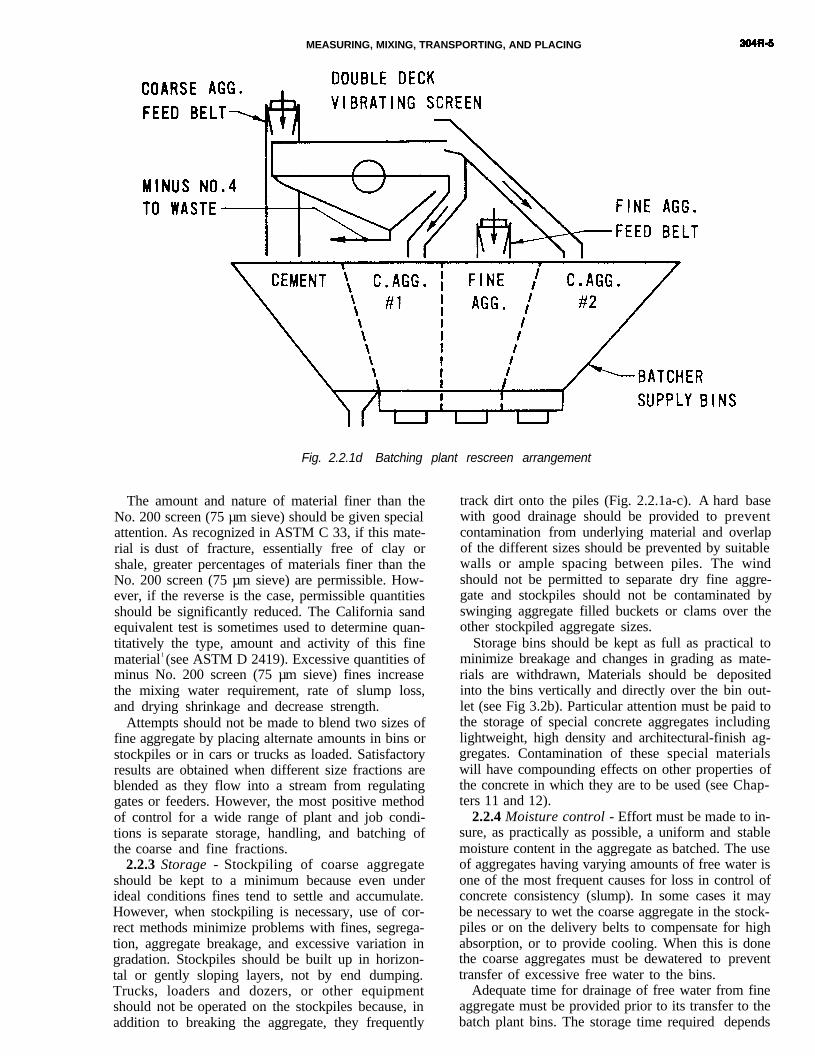
2.2.1.2 Control of undersize material - Under-size material for a given aggregate fraction is definedas that material which will pass a sieve having anopening five-sixths of the nominal minimum size ofeach aggregate fraction. 2 In Example 1 above, thatwould be material passing the following sieves: No. 5(4.0 mm), 5/8 in. (16.0 mm), 1¼ in. (31.5 mm) and 2½in. (63 mm). For effective control of gradation, it isessential that handling operations do not signifi- cantly increase the undersize materials in aggregatesprior to their use in concrete (Fig. 2.2,1a-d). The gra-dation of aggregate as it enters the concrete mixershould be uniform and within specification limits.Sieve analyses of coarse aggregate should be madewith sufficient frequency to assure that grading re-quirements are being met. When two or more aggre-gate sizes are being used, changes in the proportionsof the sizes should be made as required to improvethe overall grading of the combined aggregate. Whenspecification limits for grading cannot be met consis-tently, special handling methods should be in-stituted. Materials tend to segregate duringtransportation and reblending may be desirable. Re-screening the coarse aggregate, as it is charged to thebins at the batch plant, to waste or remove undersizematerials will effectively eliminate undesirable fineswhen usual storage and handling methods are notsatisfactory. Undersize materials in the smallercoarse aggregate fractions can be consistently re-duced to as low as two percent by rescreening (seeFig. 2.2.ld).
2.2.2. Fine aggregate (sand) - Fine aggregateshould be controlled to minimize variations in gra-dation, with special attention to keeping finer frac-tions uniform and exercising care to avoid excessiveremoval of fines during processing.
If the ratio of fine to coarse aggregate is adjusted inaccordance with ACI 211.1 recommendations formix proportioning, a wide range of fine aggregategradings can be used.3 However, variations in gradingduring production of concrete must be minimized,and the ASTM C 33 requirement that the finenessmodulus of the fine aggregate be maintained within0.20 of the design value should be met.

304R-4 MANUAL OF CONCRETE PRACTICE
INCORRECT METHODS OF STOCKPILING AGGREGATESCAUSE SEGREGATION AND BREAKAGE
a.
PREFERABLEOBJECTIONABLE
CRANE OR OTHER MEANS OF PLACING MATERIAL INPILE IN UNITS NOT LARGER THAN A TRUCK LOADWHICH REMAIN WHERE PLACED AND DO NOT RUNDOWN SLOPE.
METHODS WHICH PERMIT THE AGGREGATE TO ROLLDOWN THE SLOPE AS IT IS ADDED TO THE PILEOR PERMlT HAULING EQUIPMENT TO OPERATE OVERTHE SAME LEVEL REPEATEDLY
LIMITED ACCEPTABILITY-GENERALLY OBJECTIONABLE
PILE BUlLT RADIALLY IN HORIZONTAL LAYERS BY BULLDOZER OR FRONT LOADER STACKING PROGRESSIVE LAYERS ONBULLD0ZER OR FRONT LOADER WORKING FROM MATERIALS AS SLOPE NOT FLATTER THAN 3:1. UNLESS MATERIALSDROPPED FROM CONVEYOR BELT. A ROCK LADDER MAY STRONGLY RESIST BREAKAGE, THESE METHODS AREBE NEEDED IN SETUP. ALSO OBJECTIONABLE.
b. C.
CORRECT
CHlMNEY SURROUNDING MATERlAL FALLlNGFROM END Of CONVEYOR BELT TO PREVENTWIND FROM SEPARATING FINE AND COARSEMATERIALS. OPENINGS PROVIDED AS REQUIREDTO DISCHARGE MATERIALS AT VARIOUSELEVATIONS ON THE PILE.
INCORRECT
FREE FALL OF MATERIAL FROM HIGH END WHEN STOCKPILING LARGE SIZED AGGREGATESOF STACKER PERMITTING WIND TO SEPARATE FROM ELEVATED CONVEYORS, BREAKAGE ISFINE FROM COARSE MATERIAL MINlMlZED BY USE OF A ROCK LADDER.
UNFINISHED OR FINE AGGREGATE STORAGE FINISHED AGGREGATE STORAGE(DRY MATERIALS)
NOTE: IF EXCESSIVE FINES CANNOT BE AVOIDED IN COARSE AGGREGATE FRACTlONS BY STOCKPILING METHODS USED, FINISHSCREENING PRIOR TO TRANSFER TO BATCH PLANT BINS WILL BE REQUIRED.
Fig. 2.2. 1a-c Correct and incorrect methods of handling and storing aggregates
MEASURING, MIXING, TRANSPORTING, AND PLACING
Fig. 2.2.1d Batching plant rescreen arrangement
The amount and nature of material finer than theNo. 200 screen (75 µm sieve) should be given specialattention. As recognized in ASTM C 33, if this mate-rial is dust of fracture, essentially free of clay orshale, greater percentages of materials finer than theNo. 200 screen (75 µm sieve) are permissible. How-ever, if the reverse is the case, permissible quantitiesshould be significantly reduced. The California sandequivalent test is sometimes used to determine quan-titatively the type, amount and activity of this finematerial1 (see ASTM D 2419). Excessive quantities ofminus No. 200 screen (75 µm sieve) fines increasethe mixing water requirement, rate of slump loss,and drying shrinkage and decrease strength.
Attempts should not be made to blend two sizes offine aggregate by placing alternate amounts in bins orstockpiles or in cars or trucks as loaded. Satisfactoryresults are obtained when different size fractions areblended as they flow into a stream from regulatinggates or feeders. However, the most positive methodof control for a wide range of plant and job condi-tions is separate storage, handling, and batching ofthe coarse and fine fractions.
2.2.3 Storage - Stockpiling of coarse aggregateshould be kept to a minimum because even underideal conditions fines tend to settle and accumulate.However, when stockpiling is necessary, use of cor-rect methods minimize problems with fines, segrega-tion, aggregate breakage, and excessive variation ingradation. Stockpiles should be built up in horizon-tal or gently sloping layers, not by end dumping.Trucks, loaders and dozers, or other equipmentshould not be operated on the stockpiles because, inaddition to breaking the aggregate, they frequently
track dirt onto the piles (Fig. 2.2.1a-c). A hard basewith good drainage should be provided to preventcontamination from underlying material and overlapof the different sizes should be prevented by suitablewalls or ample spacing between piles. The windshould not be permitted to separate dry fine aggre-gate and stockpiles should not be contaminated byswinging aggregate filled buckets or clams over theother stockpiled aggregate sizes.
Storage bins should be kept as full as practical tominimize breakage and changes in grading as mate-rials are withdrawn, Materials should be depositedinto the bins vertically and directly over the bin out-let (see Fig 3.2b). Particular attention must be paid to
the storage of special concrete aggregates includinglightweight, high density and architectural-finish ag-gregates. Contamination of these special materialswill have compounding effects on other properties ofthe concrete in which they are to be used (see Chap-ters 11 and 12).2.2.4 Moisture control - Effort must be made to in-sure, as practically as possible, a uniform and stablemoisture content in the aggregate as batched. The useof aggregates having varying amounts of free water isone of the most frequent causes for loss in control ofconcrete consistency (slump). In some cases it maybe necessary to wet the coarse aggregate in the stock-piles or on the delivery belts to compensate for highabsorption, or to provide cooling. When this is donethe coarse aggregates must be dewatered to preventtransfer of excessive free water to the bins.
Adequate time for drainage of free water from fineaggregate must be provided prior to its transfer to thebatch plant bins. The storage time required depends

304R-6 MANUAL OF CONCRETE PRACTICE
primarily on the grading and particle shape of theaggregate. Experience has shown that a free moisturecontent of as high as 6 percent and occasionally ashigh as 8 percent can be stable in fine aggregate.However, tighter controls may be required for certainjobs. The use of moisture meters to indicate varia-tions in the moisture of the fine aggregate as batched,and the use of moisture compensators for rapid batchweight adjustments can minimize the influence ofmoisture variations in the fine aggregate.4,5
2.2.5 Samples for test - Samples representing thevarious aggregate sizes batched should be obtainedas closely as possible to the point of their introduc-tion into the concrete. The difficulty in obtainingrepresentative samples increases with the size of theaggregate. Therefore, sampling devices require care-ful design if meaningful test results are to be ob-tained, Methods of sampling aggregates are outlinedin detail in ASTM D 75.
It is good practice to maintain a running averageon from 5 to 10 previous gradation tests, droppingthe results of the oldest and adding the most recentto the total on which the average is calculated. Thisaverage gradation can then be used for both qualitycontrol and for proportioning purposes.
2.3-Cement
All cement should be stored in weathertight, prop-erly ventilated structures to prevent absorption ofmoisture.
Storage facilities for bulk cement should includeseparate compartments for each type of cement used.The interior of a cement silo should be smooth with aminimum bottom slope of 50 deg from the horizontalfor a circular silo and 55 to 60 deg for a rectangularsilo, Silos should be equipped with nonclogging airdiffuser flow pads through which small quantities ofdry, oil-free, low-pressure air, approximately 3 to 5psi (21 to 34 kPa) may be introduced intermittentlyto loosen cement which has settled tightly in thesilos. Storage silos should be drawn down fre-quently, preferably once per month, to prevent ce-ment caking.
Each bin compartment from which cement isbatched should include a separate gate, screw con-veyor, air slide, rotary feeder, or other conveyancewhich effectively combines characteristics of con-stant flow with precise cut off to obtain accuratebatching of cement.
Care must be used to prevent cement being trans-ferred to the wrong silo, whether by faulty pro-cedures or equipment. Fugitive dust should becontrolled during loading and transferring.
Bags of cement should be stacked on pallets orsimilar platforms to permit proper circulation of air.For a storage period of less than 60 days, it is recom-mended that the bags be stacked no higher than 14layers, and for long periods, no higher than 7 layers.AS an additional precaution, it is recommended that,insofar as practical, the oldest cement be used first.
2.4-Admixtures
Fly ash, ground slag and other finely divided orpowdered admixtures should be handled, conveyedand stored in the same manner as cement (see ACI212.2R). However, fly ash bins should be completelyseparate from cement bins, without common walls,which might allow fly ash to leak into the cementbin. Care must be taken to assure that fly ash is notloaded into a cement bin by mistake on delivery (seeSection 3.4.1).
In practice, most chemical admixtures are deliv-ered in liquid form. Care should be taken to protectliquid admixtures from freezing. If frozen, proper re-blending or mixing of the admixture should be donebefore it is used in concrete. Manufacturers’ recom-mendations should be followed.
Long term storage of liquid admixtures in ventedtanks should be avoided. Evaporation of a portion ofthe liquid could adversely affect the admixtures’ per-formance (see ACI 212).
CHAPTER 3-MEASUREMENT AND BATCHING
3.1 - General requirements
3.1.1. Objectives - An important objective in pro-ducing concrete is to obtain uniformity and homo-geneity as indicated by such physical properties asunit weight, slump, air content, strength, and air-freeunit weight of mortar in individual batches and suc-cessive batches of the same mixture proportions 2,6,7
(ASTM C 94, CE-CW-03305). During measurementoperations aggregates should be handled to maintainthe desired grading, and all materials should bemeasured within the tolerances required for desiredreproducibility of the concrete mix selected. Anotherimportant objective of successful batching is theproper sequencing and blending of the ingredients.6,7
Visual observation of each material being batched ishelpful to achieving this objective.
3.1.2 Tolerances - Most engineering organiza-tions, both public and private, issue specificationscontaining detailed requirements for manual, semi-automatic, partially automatic and automatic batch-ing equipment for concrete2 (CE-CW-03305, ASTM C94 and AASHTO). Batching equipment currentlymarketed will operate within the usual specifiedbatch weight tolerances when the equipment ismaintained in good mechanical condition. A fre-quently used document for specifying batching andscale accuracy is the "Concrete Plant Standards ofthe Concrete Plant Manufacturer’s Bureau."8,9 Batch-ing tolerances frequently used are given in Table3.1.2.
Other commonly used requirements include beamor scale divisions of 0.1 percent of total capacity andbatching interlock of 0.3 percent of total capacity atzero balance;8 quantity of admixture weighed neverto be so small that 0.4 percent of full scale capacity
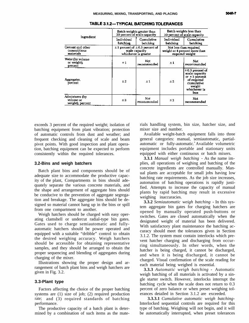
MEASURING, MIXING, TRANSPORTING, AND PLACING
exceeds 3 percent of the required weight; isolation ofbatching equipment from plant vibration; protectionof automatic controls from dust and weather; andfrequent checking and cleaning of scale and beampivot points. With good inspection and plant opera-tion, batching equipment can be expected to performconsistently within the required tolerances.
3.2-Bins and weigh batchers
Batch plant bins and components should be ofadequate size to accommodate the productive capac-ity of the plant, Compartments in bins should ade-quately separate the various concrete materials, andthe shape and arrangement of aggregate bins shouldbe conducive to the prevention of aggregate segrega-tion and breakage. The aggregate bins should be de-signed so material cannot hang up in the bins or spillfrom one compartment to another.
Weigh hatchers should be charged with easy oper-ating clamshell or undercut radial-type bin gates.Gates used to charge semiautomatic and fully-automatic hatchers should be power operated andequipped with a suitable “dribble” control to obtainthe desired weighing accuracy. Weigh hatchersshould be accessible for obtaining representativesamples, and they should be arranged to obtain theproper sequencing and blending of aggregates duringcharging of the mixer.
Illustrations showing the proper design and ar-rangement of batch plant bins and weigh hatchers aregiven in Fig. 3.2.
3.3-Plant type
Factors affecting the choice of the proper batchingsystems are (1) size of job; (2) required productionrate; and (3) required standards of batchingperformance.
The productive capacity of a batch plant is deter-mined by a combination of such items as the mate-
rials handling system, bin size, hatcher size, andmixer size and number.
Available weight-batch equipment falls into threegeneral categories: manual, semiautomatic, partial-automatic or fully-automatic.8 Available volumetricequipment includes portable and stationary unitsequipped with either continuous or batch mixers.
3.3.1 Manual weigh batching - As the name im-plies, all operations of weighing and batching of theconcrete ingredients are controlled manually. Man-ual plants are acceptable for small jobs having lowbatching rate requirements. As the job size increases,automation of batching operations is rapidly justi-fied. Attempts to increase the capacity of manualplants by rapid batching may result in excessiveweighing inaccuracies.
3.3.2 Semiautomatic weigh batching - In this sys-tem aggregate bin gates for charging hatchers areopened by manually operated push-buttons orswitches. Gates are closed automatically when thedesignated weight of material has been delivered.With satisfactory plant maintenance the batching ac-curacy should meet the tolerances given in Section3.1.2. The system must contain interlocks which pre-vent hatcher charging and discharging from occur-ring simultaneously. In other words, when thehatcher is being charged, it cannot be discharged,and when it is being discharged, it cannot becharged. Visual confirmation of the scale reading foreach material being weighed is essential.
3.3.3 Automatic weigh batching - Automaticweigh batching of all materials is activated by a sin-gle starter switch. However, interlocks interrupt thebatching cycle when the scale does not return to 0.3percent of zero balance or when preset weighing tol-erances detailed in Section 3.1.2 are exceeded.
3.3.3.1 Cumulative automatic weigh batching-Interlocked sequential controls are required for thistype of batching. Weighing will not begin, and it willbe automatically interrupted, when preset tolerances

304R-8 MANUAL OF CONCRETE PRACTICE
Fig. 3.2 Correct and incorrect methods of batching

MEASURING, MIXING, TRANSPORTING, AND PLACING 304R-9
in any of the successive weighings exceed valuessuch as those given in Section 3.1.2. The chargingcycle will not begin when the hatcher discharge gateis open, and the hatcher discharge cycle will not be-gin when hatcher charging gates are open or whenany of the indicated material weights are not withinapplicable tolerances. Presetting of desired batchweights is done by such devices as punched cards,digit switches or rotating dials and computers. Set-ting of weights, starting the batch cycle, and dis-charging the batch are all manually controlled. Mixand batch-size selectors, aggregate moisture meters,manually controlled fine aggregate moisture com-pensators, and graphic or digital devices for record-ing the batch weight of each mater ia l aresupplementary equipment that should be requiredfor good plant control .4,5 This type of batching systemprovides greater accuracy for high speed productionthan either the manual or semiautomatic systems. Itmay have a single graphic recorder for each scale or aseries of scales may simultaneously record on a sin-gle graphic chart. Also, the chart for each scaleshould not be less than 4 in. (100 mm) wide and haveone line for each 2 percent of scale capacity, but notmore than 25 lines per in. (one line per millimeter).The recorder reading should agree with the readingshown on the scale within one gradation of therecorder.
A digital recorder may have a single measuringdevice for each scale or a series of measuring devicesmay record on the same tape or ticket. This type ofrecorder shall reproduce the reading of the scalewithin 0.1 percent of the scale capacity or one incre-ment of any volumetric batching device.
A digital batch documentation recorder should re-cord information on each material in the mixturealong with the concrete mixture identification, sizeof batch, and production facility identification. Re-quired information may be preprinted, written, orstamped on the document. The recorder should pro-duce the number of documents needed and mayidentify the load by a batch count number or a ticketserial number. The recorder, if interlocked to an auto-matic batching system, should show a single indica-tion of all batching systems meeting zero or emptybalance interlocks.
Recorders should produce two or more ticketswith the data previously stated and space for theidentification of the job or project, location of place-ment, sand moisture content, the delivery vehicle,driver’s signature, purchaser’s representative’s sig-nature, and the amount of water added at the projectsite.
3.3.3.2 Individual automatic weigh batching -This system provides separate scales and hatchers foreach aggregate size and for each other materialbatched. The weighing cycle is started by a singlestart switch, and individual hatchers are charged si-multaneously. Interlocks for interrupting weighingand discharge cycles when tolerances are exceeded;
mixture selectors; aggregate moisture meters andcompensators; and recorders differ only in detailfrom those described for cumulative automaticbatching systems.
3.3.4 Volumetric batching - When aggregates orcementitious materials are batched by volume themethod of batching is considered volumetric. It isnormally a continuous operation coupled with con-tinuous mixing. Accurate volumetric batching isachieved by passing material through a calibrated ro-tary vane feeder, conveying material through a cali-brated gate opening or by any other method thatwould provide a known volume in a calibrated unittime.
Volumetric batching is suitable for the productionof most concretes, provided the equipment is oper-ated in accordance with ASTM C 685, and with thesame attention to detail as that required for weighbatching. The available equipment is highly mobile,requires little or no set-up time, and often serves asits own material transport. In many cases it isequipped with a continuous mixer (see Chapter 4,and can be adjusted to change the mixture propor-tions almost instantaneously.
3.3.4.1 Calibration - When recent experiencewith a specific piece of equipment and the materialsto be used is not available, calibration of the equip-ment is required. The calibration should be per-formed in accordance with ASTM C 686 and therecommendation of the manufacturer. The purpose ofthis calibration is to provide the operator (and thepurchaser) with the necessary meter, gauge, revolu-tion counter readings, and control settings needed toproduce the product desired.
3.3.4.2 Operation - As with any equipment op-eration it is essential that personnel responsible forcontrol be knowledgeable in all phases of its use.Operators must understand the ramifications of mak-ing adjustments because any change in the systemcould have an adverse affect on concrete quality. Ad-ditionally, care should be exercised to insure thatingredients used in production are the same, and inthe same state, as those used for calibration. Theequipment should be recalibrated when there is achange in material source or condition, when there isa change of operation, and/or when a significantchange in proportions is noted.
Because of the potential for variability, the mixshould be checked for air content, slump and yield atleast once per day of production or at intervals notexceeding 100 cu yd (80 m3) of production.
3.4-Cementitious materials
3.4.1 Batching - For high production requiringrapid and accurate batching it is recommended thatbulk cementitious materials be weighed with auto-matic, rather than semiautomatic or manual, equip-ment. All equipment should provide access forinspection and permit sampling at any time. The
304-10 MANUAL OF CONCRETE PRACTICE
bins and weigh hatchers should be equipped withaeration devices and/or vibrators to aid in the smoothand complete discharge of the batch. Return to zeroand weighing tolerance interlocks described in Sec-tion 3.1.2 should be used. Cement should be batchedseparately and kept separate from all ingredients be-fore discharging. When both cement and pozzolan orslag are to be batched, separate silos should be used.However, they may be batched cumulatively, if thecement is weighed first.
3.4.2 Discharging - Effective precautions shouldbe taken to prevent loss of cementitious materialsduring mixer charging. At multiple-stop plants,losses should be minimized by discharging the ce-mentitious materials through a rubber drop chute. Atone-stop plants, cement and pozzolan can be suc-cessfully charged along with the aggregate throughrubber telescopic dropchutes. For plant mixers, apipe should be used to discharge the cementitiousmaterials to a point near the center of the mixer afterthe water and aggregates have started to enter themixer. Proper and consistent sequencing and blend-ing of the various ingredients into the mixer duringthe charging operation will contribute significantlytoward the maintenance of batch-to-batch uniformityand perhaps reduced mixing time when confirmedby mixer performance tests6,10 (see ASTM C 94).
3.5-Water measurement
3.5.1 Batching equipment - On large jobs and incentral batching and mixing plants where high pro-duction is required, accurate water measurement canonly be obtained by the use of automatic weighhatchers or meters. Equipment and methods usedshould, under all operating conditions, be capable ofroutine measurement within the one percent toler-ance specified in Section 3.1.2. Tanks or vertical cyl-inders with center siphon discharge can bepermitted as an auxiliary part of the weighing, butshould not be used as the direct means of measure-ment. For accurate measurement a digital gallon (li-ter) meter should be used. Water glass measurementis the least desirable. All equipment for water meas-urement should be designed for easy calibration sothat accuracy of measurement can be quicklyverified.
3.5.2 Aggregate moisture determination and com-pensation - Measurement of the correct total mixingwater depends on accurately knowing the quantityand variation of moisture in the aggregate (particu-larly in the sand) as it is batched. Aggregate which isnot saturated surface dry will absorb mix water fromthe concrete, Sand moisture meters are frequentlyused in plants, and when properly maintained dosatisfactorily indicate changes in sand moisture con-tent. Moisture compensating equipment can also beused which will, by a single setting, reproportionwater and fine aggregate weight; for a change in ag-gregate moisture content. Compensators are usually
used on the sand, but occasionally they also are usedon the smallest coarse aggregate size fraction. Themoisture setting on the compensators is made manu-ally with the calibrated dials, buttons, or levers pro-vided. To date, the results obtained from moisturemeters have not been sufficiently accurate to warrantinterlocking them with compensators for automaticoperation. However, their individual use is recom-mended, and when used in conjunction with regu-larly performed conventional moisture control tests,they can be useful tools for maintaining satisfactorycontrol of the mixing water content.
3.5.3 Total mixing water - Uniformity in the meas-urement of total mixing water involves, in addition tothe accurate weighing of added water, control of suchadditional water sources as mixer wash water, ice,and free moisture in aggregates. One specified toler-ance (ASTM C 94) for accuracy in measurement oftotal mixing water, for all sources, is ±3 percent.
Use of admixtures in concrete is a universally ac-cepted practice. Batching tolerances (Section 3.1.2)and charging and discharge interlocks described pre-viously for other mixture ingredients should also beprovided for admixtures. Batching and dispensingequipment used should be readily capable of calibra-tion. When timer activated dispensers are used forlarge volume admixtures such as calcium chloride,visual graduated check tubes should be used in con-junction with the batching operation.
3.6-Measurement of admixtures
For additional information on recommended prac-tices in the use and dispensing of admixtures in con-crete, the reader is referred to the ACI 212.2R.
3.7-Measurement of materials for small jobs
If the concrete volume on a job is small, it may notbe practical to establish and maintain a batch plantand mixer at the construction site. In such cases itmay be preferable to use ready mixed concrete ormobile volumetric batching and continuous mixingequipment. If neither is available, precautions mustbe taken to properly measure and batch concrete ma-terials mixed on the jobsite. Bags of cementitious ma-terials should be protected from moisture andfractional bags should not be used unless they areweighed. The water measuring device should be ac-curate and dependable, and the mixer capacityshould not be exceeded.
In addition to accurate measurement of materials,correct operating procedures must also be used ifconcrete uniformity is to be maintained. Care shouldbe taken to insure that the batched materials areproperly sequenced and blended so that they arecharged uniformly into the mixture.6,7 The batchingplant control room, if possible, should be arranged
MEASURING, MIXING, TRANSPORTING, AND PLACING 304R-11
with the plant operator’s station located in a positionwhere the operator can closely and clearly see thescales and measuring devices during batching of theconcrete, as well as the charging, mixing, and dis-charging of the mixes, without leaving his operatingconsole, Some common batching deficiencies to beavoided are:
1. Overlapping of batches.2. Loss of materials.3. Loss or hanging up of a portion of one batch, or
its inclusion with another.
CHAPTER 4-MIXING AND TRANSPORTING
4.1 -General requirements
Thorough mixing is essential for the production ofuniform quality concrete. Therefore, equipment andmethods used should be capable of effectively mix-ing concrete materials containing the largest spec-ified aggregate to produce uniform mixtures of thelowest slump practical for the work. Recommenda-tions on maximum aggregate size and slump to beused for various types of construction are given inACI 211.1 for concretes made with ASTM C150 andC595 cements, and in ACI 223 for concretes madewith ASTM C845 expansive hydraulic cements. Suf-ficient mixing as well as transporting and placingcapacity should be provided so that unfinished con-crete lifts can be maintained plastic and free fromcold joints.
4.2-Mixing equipment
Mixers are either stationary parts of central mixplants or portable equipment. Satisfactorily de-signed mixers have a blade arrangement and drumshape which insure an end-to-end exchange of mate-rials parallel to the axis of rotation or a rolling, fold-ing, and spreading movement of the batch over itselfas it is being mixed. For additional descriptions ofsome of the various mixer types, refer to the "Con-crete Plant Mixer Standards of the Mixer Manufac-turers Division of the Concrete Plant ManufacturersBureau."11,67
The more common types of mixing equipment are:4.2.1 Tilting drum mixer - This is a revolving
drum mixer that discharges by tilting the axis of thedrum. In the mixing mode, the drum axis can beeither horizontal or at an angle to the horizontal.
4.2.2 Non-tilting drum mixer - This is a revolvingdrum mixer which is charged, mixes and dischargeswith the axis of the drum horizontal.
4.2.3 Vertical shaft mixer - This is often called aturbine or pan type mixer. Mixing is done with rotat-ing blades or paddles, mounted on a vertical shaft, ineither a stationary pan or one rotating in the oppositedirection to the blades. The batch can be easily ob-served and rapidly adjusted, if necessary. Rapid mix-ing and low overall profile are other significant
advantages. This mixer does an excellent job of mix-ing relatively dry concretes and is often used for lab-oratory mixing and by concrete p r o d u c t smanufacturers.
4.2.4 Puddle mixer - This mixer uses horizontalblades and is suitable for harsh, stiff concrete mix-tures. It is used primarily in the production of con-crete block units.
4.2.5 Truck mixers - There are two types of revolv-ing drum truck mixers in use today-rear dischargeand front discharge. The rear discharge, inclined axismixer predominates. Both utilize fins attached to thedrum to mix concrete in the mixing mode and thesame fins discharge the concrete when drum rotationis reversed.
4.3-Central mixed concrete
Central mixed concrete is mixed completely in astationary mixer and then transferred to anotherpiece of equipment for delivery. This transportingequipment can be a ready-mix truck operating as anagitator or it may be an open top truck body with orwithout an agitator. The tendency of concrete to seg-regate limits the distance it may be hauled in equip-ment not equipped with an agitator.
Sometimes the central mixer will partially mix theconcrete with the final mixing and transporting donein a revolving drum truck mixer, This process is oftencalled “shrink-mixing” as it reduces the volume ofthe “as charged” mixture. The total volume that atruck can handle is limited to 63 percent of the drumvolume.
4.4-Truck mixed concrete
Truck mixing is a process by which previouslyproportioned concrete materials from a batch plantare charged into a ready-mix truck for mixing anddelivery to the construction project. To achieve thor-ough mixing, total absolute volume of all ingredientsbatched in a revolving drum truck mixer should notexceed 63 percent of the drum volume.15 (see ASTMC 94).
4.5-Charging and mixing
The method and sequence of charging mixers is ofgreat importance in determining whether the con-crete will be properly mixed.
For central plant mixers, obtaining a preblendingor ribboning effect as the stream of materials flowinto the mixer is essential.6,7,10
In truck mixers all loading procedures must be de-signed to avoid packing of the material, particularlysand and cement, in the head of the drum duringcharging, The probablity of packing is decreased by
304-R12 MANUAL OF CONCRETE PRACTICE
placing about 10 percent of the coarse aggregate andwater in the mixer drum before the sand and cement.
The handling of water deserves special attention.Generally about one-fourth to one-third of the watershould be added to the discharge end of the drumafter all other ingredients have been charged. Watercharging pipes must be of proper design and of suffi-cient size so that water enters at a point well insidethe mixer and charging is complete within the first25 percent of the mixing time.10 Refer to Section4.5.3.1 for additional discussion of mixing water.
Chemical admixtures should be charged to themixer at the same point in the mixing sequencebatch after batch. Liquid admixtures should becharged with the water or on damp sand, andpowdered admixtures should be ribboned into themixer with other dry ingredients. When more thanone admixture is used, each should be batched sepa-rately unless premixing is shown to be permissibleand they should be properly diluted before they en-ter the mixer.
4.5.1 Central mixing -Procedures for chargingcentral mixers are less restrictive than those neces-sary for truck mixers. This is because a revolvingdrum central mixer is not charged as full as a truckmixer and the blading and mixing action is quitedifferent. In a truck mixer there is very little foldingaction compared to that in a stationary mixer. How-ever, batch size should not exceed the manufacturers’rated capacity as marked on the mixer name plate.
The mixing time required should be based uponthe ability of the mixer to produce uniform concretethroughout the batch and from batch to batch. Manu-facturers’ recommendations and usual specifica-tions, such as 1 min for 1 cu yd (¾ m3) plus ¼ min foreach additional cubic yard (cubic meter) of capacitycan be used as satisfactory guides for establishinginitial mixing time. However, final mixing timesused should be based on the results of mixer per-formance tests made at frequent intervals throughoutthe life of the job2,6,12 (see ASTM C 94 and CE-CRD-CSS). The mixing time should be measured from thetime all ingredients are in the mixer. Batch timerswith audible indicators used in combination withinterlocks which prevent under or over mixing of thebatch and discharge prior to completion of a presetmixing time should be provided on automatic plantsand are also desirable on manual plants. The mixershould be designed for starting and stopping underfull load.
4.5.2 Truck mixing - Generally, 70 to 100 revolu-tions at mixing speed are specified for truck mixing.With optimum charging sequences many truck mix-ers are able to produce uniformly mixed concrete in30 to 40 revolutions.
ASTM C 94 limits the total number of revolutionsto a maximum of 300. This is to limit grinding softaggregates, loss of slump, wear on the mixer andother undesirable effects on concrete in hot weather.
Final mixing may be done at the producer’s yard,
enroute to a project or, more commonly, it is done atthe project site.
If additional time elapses after mixing and beforedischarge, the drum speed is reduced to the agitationspeed or stopped. Then prior to discharging, themixer should be operated at mixing speed for ap-proximately 30 revolutions to enhance uniformity.
4.5.2.1 Extending transportation time - Theseprocedures are often called “dry batching” and wereevolved to accommodate long hauls and unavoidabledelays in placing by attempting to postpone the mix-ing of cement with water. However, when cement anddamp aggregate come in contact with each other, freemoisture on the aggregate does result in some cementhydration. Therefore, materials cannot be held in thismanner indefinitely.
In one method, the dry materials are batched intothe ready-mix truck and transported to the jobsitewhere all of the mixing water is added. Water must beadded under pressure, preferably at both front andrear of the drum with it revolving at mixing speed,and then mixing is completed with the usual 70 to100 revolutions. The total volume of concrete thatcan be transported in truck mixers by this method isthe same as for regular truck mixing, 63 percent ofthe drum vo1ume15 (see ASTM C 94).
4.5.3 Water4.5.3.1 Mixing water - The water required for
proper concrete consistency (slump) is affected bysuch things as amount and rate of mixing, length ofhaul, time of unloading and ambient temperatureconditions. In cool weather or for short hauls andprompt delivery, such problems as loss or variationin slump, excessive mixing water requirements, anddischarging, handling and placing problems rarelyexist. However, the reverse is true when rate of deliv-ery is slow or irregular, haul distances are long andweather is warm. Loss of workability during warmweather can be minimized by expediting deliveryand placement and by controlling the concrete tem-perature. It may also be desirable to use a retarder toprolong the time the concrete will respond to vibra-tion after is is placed. When feasible all mixing watershould be batched at the central plant. However, inhot weather it is desirable to withhold some of themixing water until the mixer arrives at the job. Thenwith the remaining required water added, an addi-tional 30 revolutions at mixing speed is required toadequately incorporate the additional water into themixture, When loss of slump or workability cannotbe offset by these measures, the procedures de-scribed in Section 4.5.2.1 may also be considered.
4.5.3.2 Addition of water on the job - The max-imum water-cement ratio should never be exceeded.
If all the water allowed by the specification has notbeen added at the start of mixing it may be permissi-ble to add the remaining allowable water at the pointof delivery. It should be noted that once part of abatch has been unloaded, it becomes impractical to
MEASURING, MIXING, TRANSPORTING, AND PLACING 304R-13
determine what water-cement ratio is produced byadditional water.
The production of concrete of excessive slump oradding water in excess of the proportioned water-cement ratio to compensate for slump loss resultingfrom delays in delivery or placing should be prohib-ited. Persistent requests for the addition of watershould be investigated.
Where permitted a high-range water-reducer (su-perplasticizer) can be added to the concrete to in-crease slump while maintaining a low water-cementratio.13,14 Addition may be made by the concrete sup-plier or the contractor by a variety of techniques.When this admixture is used, vibration for consol-idation may be reduced. However, in walls and slop-ing formed concrete some vibration is necessary toremove air trapped in the form. This admixture mayalso increase form pressure.
4.5.3.3 Wash water - Most producers find it nec-essary to rinse off the rear fins between loads withthe entire mixer washed and discharged only at theend of the day. Hot weather and unusual mix designsmay require washing and discharge of wash waterafter every load. Rinse water must not be allowed toremain in the mixer unless it can be accurately com-pensated for in the succeeding batch. Pollution con-trol regulations make it increasingly difficult to washout after every load and have created an interest insystems to reclaim and reuse both wash water andreturned concrete aggregates.
ASTM C 94 describes the reuse of wash waterbased on prescribed tests. Particular attention is nec-essary when admixtures are being used because therequired dosages may change dramatically. Whenwash water is used, admixtures should be batchedinto a limited quantity of clean water or onto dampsand.
4.6-Mix temperature
Batch-to-batch uniformity of concrete from amixer, particularly with regard to slump, water re-quirement, and air content, also depends on the uni-formity of the concrete temperature. It is, therefore,important that maximum and minimum concretetemperatures be controlled throughout all seasons ofthe year. Recommendations on control of concretetemperatures are discussed in detail in ACI 305R and306R.
Mixers must be capable of discharging concrete ofthe lowest slump suitable for the structure being con-structed without segregation (separation of coarse ag-gregate from the mortar). Prior to discharge ofconcrete transported in truck mixers, the drumshould again be rotated at mixing speed for about 30revolutions to reblend possible stagnant spots nearthe discharge end into the batch (see Fig. 5.1a and b).
4.8-Mixer performance
The performance of mixers is usually determinedby a series of uniformity tests made on samples takenfrom two or three locations within the concrete batchafter it has been mixed for a given time period2,12 (seeASTM C 94 and CE-CRD-C55). Mixer performancerequirements are based on allowable differences intest results of samples from any two locations or be-tween individual locations and the average of all lo-cations. The NRMCA has a description of theseprocedures and is an excellent reference.10,12
Among the many tests used to check mixer per-formance, the following are the most common: aircontent, slump, unit weight of air-free mortar, coarseaggregate content and compressive strength.
Another important aspect of mixer performance isbatch-to-batch uniformity of the concrete which isalso affected by the uniformity of materials and theirmeasurement as well as by the efficiency of themixer. Visual observation of the concrete during mix-ing and discharge from the mixer is an important aidin maintaining a uniform mixture, particularly uni-form consistency. Some recording consistencymeters, such as those operating from the amperagedraw on the electric motor drives for revolving drummixers, have also proved to be useful. However, themost positive control method for maintaining batch-to-batch uniformity is a regularly scheduled programof tests of the fresh concrete including unit weight,air content, slump, and temperature. Althoughstrength tests provide an excellent measure of theefficiency of the quality control procedures that areemployed, the strength test results are available toolate to be of practical use in controlling day to dayproduction.
Mixers should be properly maintained to preventmortar and dry material leakage. Inner mixer sur-faces should be kept clean and worn blades replaced.Mixers not meeting the performance tests referencedin Section 4.8 should be taken out of service untilnecessary maintenance and repair results in correc-tion of their deficient performance.
4.10-General considerations for transportingconcrete
4.10.1 General - Concrete can be transported by avariety of methods and equipment, such as truckmixers, open top truck bodies with and without agi-tators, buckets hauled by truck or railroad car, bypipeline, hose or conveyor belts. The method oftransportation used should efficiently deliver theconcrete to the point of placement without signifi-cantly altering its desired properties with regard towater-cement ratio, slump, air content and homoge-neity. Each method of transportation has advantagesunder particular conditions such as: mixture ingre-
304R-14 MANUAL OF CONCRETE PRACTICE
CHAPTER 5-PLACING CONCRETE
dients and proportions, type and accessibility ofplacement, required delivery capacity, location ofbatch plant, weather conditions, and others. Thesevarious conditions should be carefully reviewed inselecting the type of transportation best suited foreconomically obtaining quality concrete in place.4.10.2 Revolving drum - By this method, the truckmixer previously described serves as an agitatingtransportation unit. The drum is rotated at chargingspeed during loading and is reduced to agitatingspeed or stopped after loading is complete. Theelapsed time before discharging the concrete can bethe same as for truck mixing and the volume carriedmay be increased to 80 percent of the drum capacity(see ASTM C 94).
4.10.3 Truck body with and without an agitator -Units used in this form of transportation usuallyconsist of an open-top body mounted on a truck,although bottom dump trucks have been used suc-cessfully. The metal body should have smoothstreamlined contact surfaces and is usually designedfor discharge of the concrete at the rear when thebody is tilted. A discharge gate and vibratorsmounted on the body should be provided at thepoint of discharge for control of flow. An agitator aidsin the discharge and ribbon blends the concrete as itis unloaded. Water should never be added to con-crete in the truck body because no mixing is per-formed by the agitator.
Use of protective covers for truck bodies duringperiods of inclement weather, proper cleaning of allcontact surfaces, and smooth haul roads contributesignificantly to the quality and operational effi-ciency of this form of transportation. The maximumdelivery time usually specified is 30 to 45 min, al-though weather conditions may require shorter, orpermit longer, times.
4.10.4 Concrete buckets on trucks or railroadcars - This is a common method of transportation ofmass concrete from the batch plant to a location closeto the placement area. A crane then lifts the bucket tothe final point of placement. Occasionally transfercars operating on railroad tracks are used to transportthe concrete from the batch plant to buckets operat-ing from cableways. Discharge of the concrete fromthe transfer cars into the bucket, which may be fromthe bottom or by some form of tilting, must be closelycontrolled to prevent segregation. Delivery time forbucket transportation is the same as for other non-agitating units; usually 30 to 45 min.
4.10.5 Other methods - Transportation of concreteby pumping methods and by belt conveyors will bediscussed in Chapters 9 and 10, respectively. Heli-copter deliveries have been used in difficult to reachareas, where other transporting equipment could notbe used. This system usually employs one of theother methods to transport the concrete to the heli-copter which then lifts the concrete in a lightweightbucket to the area of placement.
5.1 -General considerations
Chapter 4 described some equipment and pro-cedures for transporting concrete from the batchingor batching and mixing plant to the placing site. Thischapter presents guides for transferring concretefrom the transporting equipment to its final positionin the structure under construction.
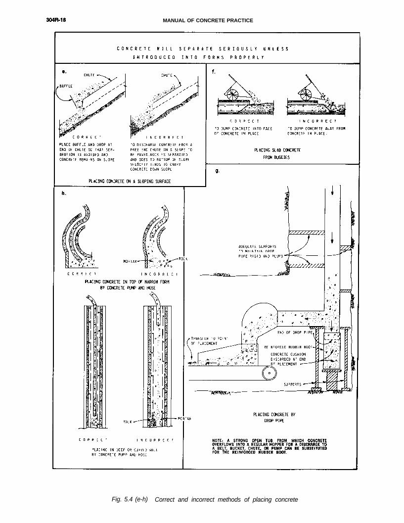
Placement of concrete is accomplished with buck-ets, hoppers, manual or motor propelled buggies,chutes and drop pipes, conveyor belts, pumps, trem-ies, and paving equipment. Figure 5.1 shows anumber of handling and placing methods discussedin this chapter and gives examples of both satisfac-tory and unsatisfactory construction procedures.
Placement of concrete by the preplaced aggregatemethod and by pumps and conveyors are discussedin Chapters 7, 9, and 10 respectively, In addition,placing methods peculiar to underwater, heavy-weight, and lightweight concreting are noted inChapters 8, 11, and 12 respectively. Another effectiveplacement technique for both mortar and concrete isthe shotcrete process in which thin layers are appliedpneumatically where forming is inconvenient or im-practical, access or location provides difficulties ornormal casting techniques cannot be employed (seeACI 506).
5.2-Planning
A basic requirement in all concrete handling isthat both quality and uniformity of the concrete, interms of water-cement ratio, slump, air content, andhomogeneity, must be preserved. The selection ofhandling equipment should be based on its ca-pability to efficiently handle concrete of the mostadvantageous proportions that can be readily consol-idated in place with vibration. Equipment which re-quires adjustment in mixture proportions beyondranges recommended by ACI 211.1 should not beused.
Advance planning should assure producing anadequate and consistent supply of concrete. Suffici-ent placing capacity should be provided so that theconcrete can be kept plastic and free of cold jointswhile it is being placed. All equipment for placingshould be clean and in proper repair. The placingequipment should be arranged to deliver the con-crete to its final position without objectionable segre-gation. The equipment should be adequately andproperly arranged so that placing may proceed with-out undue delays and manpower should be suffi-cient to assure the proper placing, consolidating, andfinishing of the concrete. If the concrete is to beplaced at night, the lighting system should be suffi-cient to illuminate the inside of the forms and toprovide a safe work place.

MEASURING, MIXING, TRANSPORTING, AND PLACING 304R-15
Fig. 5.1 Correct and incorrect methods of handling concrete
304R-16 MANUAL OF CONCRETE PRACTICE
Concrete placement should not be started whenthere is a probability of freezing temperatures occur-ring, unless adequate facilities for cold weather pro-tection have been provided (see ACI 306R). Facilitiesfor prompt commencement of curing or for the ap-plication of sealing compound should be in read-iness for use at the proper time (see ACI 308). Wherepractical, it is advantageous to have radio or tele-phone communications between the site of majorplacements and the batching and mixing plant tobetter control delivery schedules and prevent exces-sive delays and waste of concrete.
It is advisable that the concrete be delivered to thesite at a uniform rate compatible with the manpowerand equipment being used in the placing and finish-ing processes. Where an interruption in the concret-ing process could be a problem, considerationshould be given to the provision of backupequipment.
A final detailed inspection of the foundation, con-struction joints, forms, water stops, reinforcementand other items of the placement should be madeimmediately before the concrete is placed. A methodof documenting such inspection should be devel-oped and approved by all parties prior to the start ofwork. All of these features should be carefully exam-ined to make sure they are in accordance with thedrawings, specifications and good practice.
5.3-Reinforcement and embedded items
At the time of concrete placement, reinforcingsteel and embedded items should be clean and freefrom mud, oil and other coatings that may adverselyaffect bonding capacity. Most reinforcing steel is cov-ered with either mill scale or rust of some severityand such coatings are considered satisfactory pro-vided that loose rust and mill scale are removed andthat the minimum dimensions of the steel are notless than required in ACI 318.
Care should be taken to ensure that all reinforcingsteel is of the proper size and length and that it isplaced in the correct position and spliced in accor-dance with the plans. Adequate concrete cover of thereinforcing steel must be maintained.
Mortar coating on embedded items within a lift tobe completed within a few hours need not be re-moved, but loose dried mortar on embedded itemsprojecting into future lifts should be removed priorto placing those lifts.
The method of holding waterstop in the formsshould ensure that it cannot bend to form cavitiesduring concreting.
Bars and embedded items should be held securelyin the proper position by suitable supports and tiesto prevent displacement during concreting. Concreteblocks are sometimes used for support of the steel.Metal bar chairs with or without plastic protectedends or plastic bar chairs are more commonly used.Whatever system is used, there must be assurance
that the supports will be adequate to carry expectedloads before and during placement and will not stainexposed concrete surfaces, displace excessive quan-tities of concrete, nor allow bars to move from theirproper positions.16
In some cases when reinforced concrete is beingplaced, it may be advantageous to have a competentperson in attendance to adjust and correct the posi-tion of any reinforcement which may be displaced.Structural engineers should identify critical areaswhere such additional supervision would beadvantageous.
5.4-Placing
5.4.1 Precautions - Equipment should be arrangedso that the concrete has an unrestricted vertical dropto the point of the placement or into the containerreceiving it. The stream of concrete should not beseparated by permitting it to fall freely over rods,spacers, reinforcement or other embedded materials.If forms are sufficiently open and clear so that theconcrete is not disturbed in a vertical fall into place,direct discharge without the use of hoppers, trunksor chutes is usually desirable. Concrete should bedeposited at or near its final position in the place-ment because it has a tendency to segregate when ithas to be flowed laterally into place.
If monolithic placement of a deep beam, wall, orcolumn with a slab or soffit above is desired, a delayshould be scheduled to permit settlement of the deepconcrete before the slab or soffit concrete is placed.The length of delay will depend upon the tem-perature and setting characteristics of the concreteused (usually about 1 hr), but concreting should be-gin soon enough to permit a knitting of the new layerwith the old layer by vibration.
5.4.2 Equipment - When choosing placing equip-ment consideration must be given to the ability of theequipment to place the concrete in the correct loca-tion economically and without altering its quality.
The selection of equipment is influenced by themethod of concrete production. Certain types ofequipment such as buckets, hoppers, buggies, etc.will suit batch production while other equipmentsuch as belt conveyors and pumps are more suitablefor continuous production.
5.4.2.1 Buckets and hoppers - The use of prop-erly designed bottom dump buckets permits theplacement of concrete at the lowest practical slumpconsistent with consolidation by vibration. Thebucket should be self-cleaning upon discharge andconcrete flow should start upon opening of the dis-charge gate. Discharge gates should have a clearopening equal to at least fives times the maximumaggregate size being used. Side slopes should be atleast 60 deg from the horizontal.
Control of the bucket and its gate opening shouldbe done in such a manner as to ensure a steadystream of concrete discharged against previously

MEASURING, MIXING, TRANSPORTING, AND PLACING R-17
304Fig. 5.4 (a-d) Correct and incorrect methods of placing concrete
MANUAL OF CONCRETE PRACTICE
Fig. 5.4 (e-h) Correct and incorrect methods of placing concrete

MEASURING, MIXING, TRANSPORTlNG, AND PLACING 304R-19
placed concrete where possible. Stacking concrete bydischarging the bucket too close to the lift surfaceand discharging buckets while traveling are commoncauses of segregation.
In order to prevent contamination, spilled concreteshould not be shoveled back into buckets or hoppersfor subsequent use, and freshly finished concreteshould be protected by not swinging buckets directlyover it.
To expedite the placing schedule the use of twobuckets or more per crane is recommended.
5.4.2.2. Manual or motor propelled buggies-Buggies should run on smooth rigid runways inde-pendently supported and set well above reinforcingsteel. Concrete being transferred by buggies tends tosegregate during motion and planking should be but-ted rather than lapped to maintain a smooth surfaceto prevent separation of concrete materials in transit.
The recommended maximum horizontal deliverydistance to transfer concrete by manual buggies is200 ft (60 m) and for power buggies 1000 ft (300 m),Manual buggies range in capacity from 6 to 8 cu ft(0.2 m3) with placing capacity averaging from 3 to 5cu yd (2 to 4 m3) per hour. Power buggies are avail-able in sizes from 9 to 12 cu ft (0.3 m3) with placingcapacity ranging from 15 to 20 cu yd (11 to 15 m3) perhour depending upon the distance traveled.
5.4.2.3 Chutes and drop chutes - Chutes are fre-quently used for transferring concrete from upper tolower elevations. They should have rounded corners,be constructed of metal or be metal lined, and shouldhave sufficient capacity to avoid overflow. The slopeshould be constant and steep enough to permit con-crete of the slump required to flow continuouslydown the chute without segregation.
The flow of the concrete at the end of a chuteshould be controlled to prevent segregation.
Drop chutes are circular pipes used for transferringconcrete vertically from higher to lower elevations.The pipe should have a diameter of at least eighttimes the maximum aggregate size at the top 6 to 8 ft(2 to 3 m) of the chute, but may be tapered to approx-imately six times the maximum aggregate size below.It should be plumb, secure, and positioned so thatthe concrete will drop vertically.
Plastic or rubber drop chutes or tremies may beused and may be shortened by cutting them in lieu ofraising as the placement progresses. With the use ofplastic drop chutes care should be taken to ensurethat such chutes do not fold over or kink.
5.4.2.4 Paving equipment - The use of largemixers, high capacity spreaders, and slipform pavershas made it possible to place large volumes of con-crete pavement at a rapid rate. Most of the same prin-ciples of quality control are required for successfulpaving as in other forms of concrete placement. Dueto the speed of placement, routine inspection pro-cedures need to be more frequent so that detecteddeviations from acceptable quality can be corrected.
Some of the more frequent problems which can
detrimentally affect the desired quality of the con-crete in paving are also common in other types ofplacement; namely, poor batch-to-batch mixing uni-formity, variation in slump and air content, and im-proper distribution of the mortar in aggregatethroughout the placement.
Placing of concrete with paving equipment is cov-ered in ACI 316.
5.4.2.5 Slipforming - By this method concrete isplaced in prefabricated forms which are slipped pastthe point of placement as soon as the concrete hasgained dimensional stability and rigidity to retain itsdesign shape.
Careful, consistent concrete control with suitablemixture adjustments for changing ambient tem-peratures are required.
5.5-Consolidation
Internal vibration is the most effective method ofconsolidating plastic concrete for most applications.The effectiveness of an internal vibrator dependsmainly upon the head diameter, frequency and am-plitude. Detailed recommendations for equipmentand procedures for consolidation are given in ACI309.
Vibrators should not be used to move concrete lat-erally. They should be inserted and withdrawn ver-tically at close intervals, using a systematic pattern ofvibration to ensure that all concrete has been ade-quately consolidated.
As long as a running vibrator will sink into theconcrete by its own weight, it is not too late for theconcrete to benefit from revibration which shouldimprove compressive and bond strengths. There is noevidence of detrimental effects either to embeddedreinforcement or to concrete in partially hardenedlifts when they are revibrated by consolidationefforts on fresh concrete above.
In unusually difficult and obstructed placementssupplemental form vibration may be used. In thesecircumstances care should be taken to avoid exces-sive operation of the vibration units which wouldcause a weak paste surface layer.
On vertical surfaces where air void holes are objec-tionable, experience has shown that the voids can bereduced by using additional vibration. However, ex-tra vibration, spading or mechanical manipulation ofconcrete will not consistently remove air void holesfrom surfaces molded under sloping forms.
The use of experienced and competent vibrator op-erators working with well-maintained vibrators andwith a sufficient supply of standby units are essen-tial to satisfactory and successful consolidation offresh concrete.
5.6-Mass concreting
The equipment and method used for placing massconcrete should avoid separation of coarse aggregate

304R-20 MANUAL OF CONCRETE PRACTICE
Fig. 5.5 Correct and incorrect methods of consolidation
MEASURING, MIXING, TRANSPORTlNG, AND PLACING 304R-21
from the concrete. Although scattered pieces ofcoarse aggregate are not objectionable, clusters andpockets of coarse aggregate are objectionable andmust be scattered prior to placing concrete overthem. Segregated aggregate will not be eliminated bysubsequent placing and consolidation operations.
Concrete should be placed in horizontal layers notexceeding 2 ft (610 mm) in depth and inclined layersand cold joints should be avoided. For monolithicconstruction each concrete layer should be placedwhile the underlying layer is still responsive tovibration, and layers should be sufficiently shallowto permit the two layers to be knitted by propervibration.
The step method of placement should be used inmassive structures where large areas are involved inorder to minimize the occurrence of cold joints. Inthis method the lift is built up in a series of horizon-tal stepped layers 12 to 18 in. (300 to 450 mm) thick.Concrete placing on each layer extends for the fullwidth of the block, and the placing operations pro-gress from one end of the lift towards the other, ex-posing only small areas of concrete at a time. As theplacement progresses, part of the lift will be com-pleted while concreting continues on the remainder.
For a more complete discussion of mass concreteand the necessary thermal considerations see ACI207.1R.
CHAPTER 6-FORMS, JOINT PREPARATION,AND FINISHING
6.1 -Forms
Forms are the molds into which concrete is placedand falsework is the structural support and the nec-essary bracing required for temporary support duringconstruction. Formwork is the total system of sup-port for freshly placed concrete, including forms andfalsework. Formwork design should be establishedprior to erection, and shop drawings containing con-struction details, sequence of concrete placing andloading values used in the design should be ap-proved before commencement of construction. Shopdrawings should be available on site during form-work erection and when placing the concrete.
Design and construction of concrete forms shouldcomply with ACI 347. The design and constructionof concrete formwork should be reviewed to mini-mize costs without sacrificing either safety or qual-ity. Because workmanship in concrete constructionis frequently judged by the appearance of the con-crete after removal of the forms, proper performanceof formwork while bearing the plastic concreteweight and live construction loading is of vitalimportance.
Forms should be built with sufficient strength and rigidity to carry the mass and fluid pressure of con- crete and of the materials, equipment or runways that
are to be placed upon them. Fluid pressure on formsshould be correlated to the capacity and type of plac-ing equipment, the planned rate of placing concrete,the slump, temperature and stiffening characteristicsof the concrete.
Form panel joints, corners, connections, andseams should be mortar tight. Consolidation will liq-uefy the mortar in concrete, allowing it to leak fromany openings in the formwork, leaving voids, sandstreaks, or rock pockets. When forms are set for suc-ceeding lifts, bulges and offsets at horizontal jointscan be avoided by resetting forms with only 1 in, (25mm) of sheathing overlapping the concrete below theline made by the grade strip from the previous liftand by securely tying and bolting the forms close tothe joint. Rustification strips (formed grooves) canalso be used to obscure construction joints and im-prove appearance when they are well arranged.2 Theform ties used should result in the minimum prac-tical hole size and their design should permit re-moval without spalling surrounding concrete.Leakage of mortar around ties should be prevented,and filling of cone holes or other holes left by formties should be done in a manner which results in asecure, sound, nonshrinking, inconspicuous patch2
(see ACI 311). Prior to concreting, forms should beprotected from deterioration, weather, and shrinkageby proper oiling or by effective wetting. Form sur-faces should be clean and of uniform texture, andwhen reuse is permitted, they should be carefullycleaned, oiled, and reconditioned if necessary.
Steel forms should be thoroughly cleaned butnever sandblasted nor abraded to bright metal. If“peeling” of concrete is encountered when usingsteel forms, leaving the cleaned, oiled forms in thesun for a day, vigorously rubbing the affected areaswith liquid paraffin, or applying a thin coating oflacquer will usually eliminate the problem, Some-times peeling is the result of abrasion of certain formareas from impact during placement. Improvementcan be made by temporarily protecting form areassubject to abrasion with plywood or metal sheets.
Form faces should be treated with a releasing agentto prevent concrete sticking to the forms and therebyaid in stripping. The releasing agent may also act as asealer or protective coating for the forms to preventabsorption of water from the concrete into the form-work. Form coatings must be carefully chosen forcompatibility with the contact surfaces of the formsbeing used and with subsequent coatings to be ap-plied to the concrete surfaces. Form coatings that aresatisfactory on wood are not always suitable for steelforms, e.g., steel forms would require a coatingwhich acts primarily as a releasing agent, whileplywood will benefit from a coating that also sealsthe forms against moisture penetration.
Ample access should be provided within theforms for proper cleanup, placement, consolidationand inspection of the concrete.
304R-22 MANUAL OF CONCRETE PRACTICE
For the sake of appearance, it is important thatproper attention be paid to the mark made by a con-struction joint on exposed formed surfaces of con-crete. Irregular construction joints should not bepermitted. A straight line, preferably horizontal,should be obtained by filling forms to a grade strip.Rustication strips, either a vee or a beveled rec-tangular strip, can be used as a grade strip and toform a groove at the construction joint w h e nappropriate.
6.2-Joint preparation
Construction joints occur wherever concreting isstopped or delayed so that fresh concrete subse-quently placed against hardened concrete cannot beknitted to the previous placement. Horizontal con-struction joints will occur at the levels between liftswhile vertical joints occur where the structure is ofsuch length that it is not feasible to place the entirelength in one continuous operation. In general, thepreparation of a vertical construction joint for ac-ceptable performance and appearance is the same asfor horizontal joints.
The surfaces of all construction joints should becleaned and properly prepared so as to assure ade-quate bond with concrete placed on it or adjacent toit and to obtain required watertightness.2,17,18 Severalmethods of cleanup are available depending on thesize of the area to be cleaned, age of the concrete,skill of workmen, and availability of equipment. It isnot difficult to obtain a satisfactory joint when highquality low-slump concrete has been properlyplaced. Removal of sound mortar or concrete to ex-pose coarse aggregate or to create roughness is notjustified. For most construction joints, it is necessaryonly to remove laitance and expose the sand andsound surface mortar.
When large quantities of bleed water and fines arebrought to the construction joint surface, concrete atthe surface will be so inferior that obtaining adequatecleanup is difficult. This problem is compoundedwhen high-slump concrete is used. In such cases,green cutting, sand blasting, or high-pressure waterjets will be required to correctly prepare the joint.
Green cutting is the removal of all laitance andinferior surface concrete by means of a strong jet ofwater or air-water at approximately 100 psi (0.7 MPa).It must not be started until the concrete has hardenedsufficiently to prevent the jet from ravelling the sur-face below the desired depth. Care must be taken tosee that the cutting is done at the proper time, not tooearly so as to avoid too much cutting, and not too latein order to obtain sufficient removal of the surfacelaitance. Green cutting is usually performed 4 to 12hours after placement and can be successfully usedwhere the quality of the concrete at the joint is good.
Sandblasting is used to prepare the surface of theconstruction joint after the concrete has hardenedand preferably just before forms are erected for thenext placement.2,17,18 Wet sandblasting is usually pre-
ferred due to the objectionable dust associated withthe dry process. This method produces excellent re-sults on horizontal joint surfaces, particularly onthose placed with 2 in. (50 mm) (or less) slump con-crete using internal vibrators.
Another method for cleaning construction jointsutilizes a water jet under a minimum pressure of6,000 psi (40 MPa). As with the sandblast method,cleanup is delayed until the concrete is sufficientlyhard so that only the surface skin of mortar is re-moved and no undercutting of coarse aggregate parti-cles occurs.
Cloudy pools of water which will leave a weak filmon the surface when they dry should be removed bythorough washing after the main cleanup operationis completed. Cleaned joint surfaces should be con-tinuously moist cured until the next concrete place-ment or until the specified time of curing has beenfulfilled. Before placing new concrete at the joint, thesurface should be restored to the clean condition ex-isting immediately following initial cleanup. If thesurface has been properly cured, very little finalcleaning will be necessary prior to placement.
Hand tools such as wire brushes, wire brooms,hand picks, or bush-hammers may be used to removedirt, laitance, and soft mortar but are only practicalfor small areas.
Retarding agents may be used to treat concrete sur-faces after the finishing operations and before theconcrete has set. Manufacturer’s instructions for ap-plication and coverage rate should be followed. Sub-sequent removal of the unhardened surface mortar iscompleted with other cleanup methods such aswater jets, air-water jets, or hand tools. Concrete sur-faces treated with retarder should be cleaned as soonas practical after initial set, the longer the delay, theless retarded surface layer will be removed.
The clean concrete joint surface should be satu-rated, surface dry at the time new concrete is placedon it. Surface moisture weakens the joint by increas-ing the water-cement ratio of the newly placed con-crete. Care must be taken to ensure that the first layerof concrete on the construction joint is adequatelyconsolidated for good bond.
6.3-Finishing unformed surfaces
To obtain a durable surface on unformed concrete,proper procedures must be carefully followed, Theconcrete used should be of the lowest practicalslump that can be properly consolidated, preferablyby means of internal vibration. Following consolida-tion, the operations of screeding, floating, and firsttroweling should be performed in such a manner thatthe concrete will be worked and manipulated as littleas possible in obtaining the desired result. Over-manipulation brings excessive fines and water to thetop which impairs the quality of the finished surfacecausing such undesirable effects as checking, craz-ing, and dusting. For the same reason, each step inthe finishing operation, from the first floating to the
MEASURING, MIXING, TRANSPORTING, AND PLACING 304R-23
final floating or troweling, should be delayed as longas possible while still permitting the desired gradeand surface smoothness to be obtained. Free water isnot as likely to appear and accumulate between fin-ishing operations if proper mixture proportions andconsistency are used. However, if free water does ac-cumulate, it should be removed by blotting withmats, draining, or pulling off with a loop of hose, sothe surface loses its water sheen before the next fin-ishing operation is performed. Under no circum-stances should any finishing tool be used in an areabefore accumulated water has been removed, norshould neat cement or mixtures of sand and cementbe worked into the surface to dry such areas.
It is possible to obtain satisfactory results from cor-rectly designed mortar topping placed on a n dworked into base concrete before the base concretesets, The mortar consistency, consolidation, and fin-ishing should be as described above. However, a con-crete of correct proportions, consistency, and textureplaced and finished monolithically with the baseconcrete is preferable to a mortar topping.
For a detailed discussion and recommendations onconcrete floor and slab finishing, see ACI 302.lR.
Several special floor finishes which are installedover hardened concrete surfaces, such as terrazzo,require special techniques and are not covered in thisguide.
CHAPTER 7-PREPLACED AGGREGATESTRUCTURAL AND MASS CONCRETE
7.1 - General considerations
In this method of construction, forms are firstfilled with clean coarse aggregate. The voids in thiscoarse aggregate are then filled with structural qual-ity grout to produce preplaced aggregate (PA) con-crete. This type of concrete is particularly usefulwhere concrete is to be placed under water, wherestructures are heavily reinforced for seismic or otherreasons, where structural concrete or masonry is tobe repaired, or where concrete of low volume changeis required.2,19,20,21,22,23 (see CE EM-1110-2-2000).
Preplaced aggregate concrete differs from conven-tionally placed concrete in that it contains a higherpercentage of coarse aggregate; consequently, theproperties of the coarse aggregate appear to have agreater effect on the properties of the concrete. Forexample, the modulus of elasticity is slightly higherthan that of conventional concrete. Also, because ofpoint-to-point contact of the coarse aggregate, dryingshrinkage is about one-half the magnitude of that inconventionally placed concrete.23,24 However, struc-tural design for PA concrete is the same as for con-ventionally placed concrete2 (see CE EM-1110-2-2000).
Structural formwork is usually more expensive
than that required for conventionally placed con-crete because greater care is needed to prevent groutleaks. However, in underwater construction, higherplacing rates at lower cost have been achieved by thismethod than by conventional placing methods.
Since PA concrete construction is specialized innature, it is advisable that the work be undertaken byqualified personnel experienced in this method ofconstruction.
7.2.1 Cement - Grout can be made with any one ofthe non-air-entraining types of cement that complieswith ASTM C 150 or ASTM C 595. Use of air en-trained cements combined with gas-forming fluid-ifiers could result in excessive quantities ofentrained air in the mortar resulting in reducedstrengths. When air-entrainment is required to an ex-tent higher than that provided by the gas-formingfluidifier, air-entraining agent should be addedseparately.
7.2.2 Coarse aggregate - Coarse aggregate shouldbe washed, free of surface dust and fines, in confor-mance with the requirements of ASTM C 33, exceptas to grading.
The void content of the aggregate should be as lowas possible and is usually attained when the coarseaggregate is graded uniformly from the smallest al-lowable particle size to the largest size.22 Void con-tent will range from approximately 35 percent forwell-graded aggregate between ¾ in. (19 mm) and 6to 8 in. (150 to 200 mm) to as high as 50 percent forsingle-sized aggregate. Void contents as low as 25percent have been attained experimentally by delib-erate gap grading.
Gradings 1 or 2, Table 7.2, are recommended for
general use. Where reinforcement is crowded or theplacement is in relatively shallow patches, up to 10percent passing the ½ in. (12.5 mm) sieve with notmore than 2 percent passing the 3/8 in. (9.5 mm) sieve(Grading 1) may be used. Where special circum-stances dictate the use of coarser sand, Grading 3 isacceptable.7.2.3 Fine aggregate - Sand should conform toASTM C 33 except that grading should be as shownin Table 7.2. Fine aggregate that does not fall withinthese grading limits is useable provided results fallwithin the requirements of Section 7.3.
7.2.4 Pozzolan - Pozzolans conforming to ASTM C618, Class N or F, may be used. Class F has been usedin the great majority of installations since it improvespumpability of the fluid grout and extends grout han-dling time. Data from Class C fly ash use and testingare lacking.
7.2.5 Admixtures7.2.5.1 Grout fluidifier - This admixture is com-
monly used to offset the effects of bleeding, to reducethe water-cementitous materials (cement pluspozzolan) ratio for a given fluidity, and to retard stiff-ening. It normally consists of a water-reducing agent,
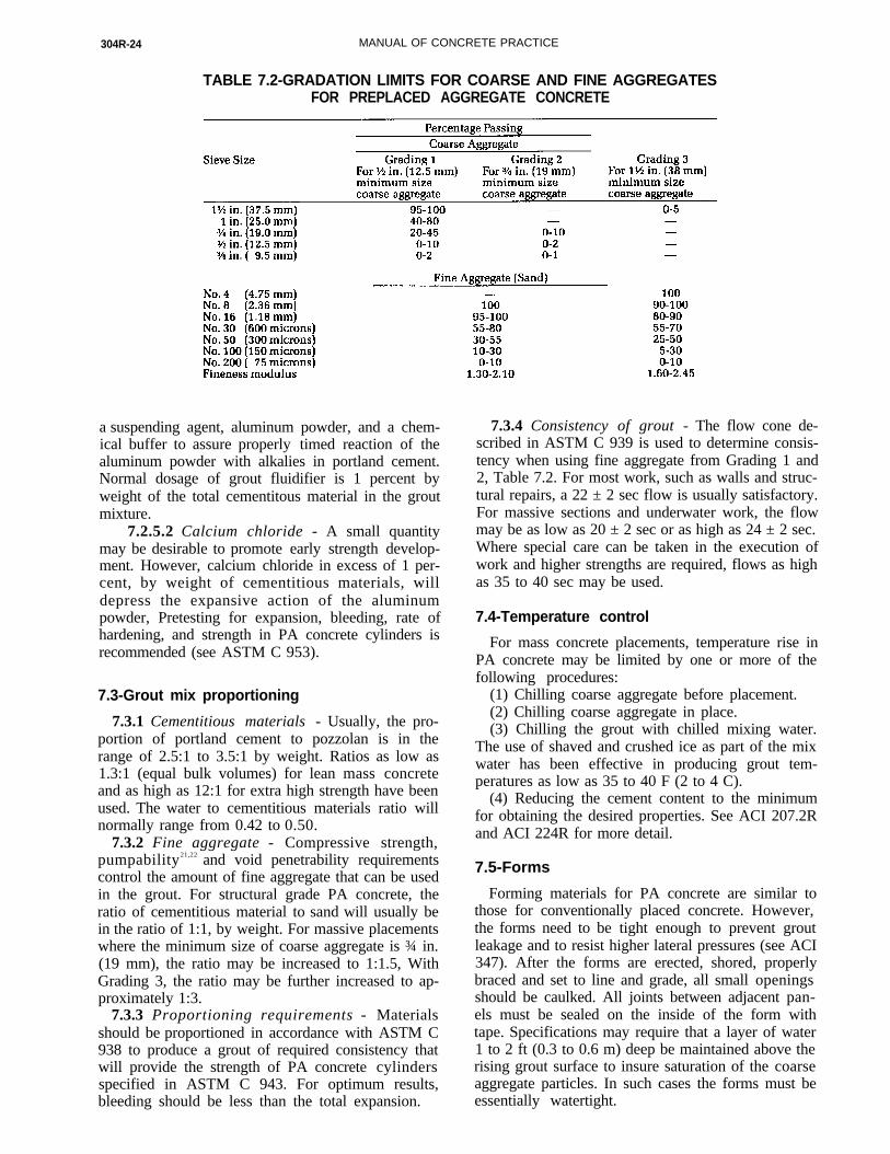
304R-24 MANUAL OF CONCRETE PRACTICE
TABLE 7.2-GRADATION LIMITS FOR COARSE AND FINE AGGREGATESFOR PREPLACED AGGREGATE CONCRETE
a suspending agent, aluminum powder, and a chem-ical buffer to assure properly timed reaction of thealuminum powder with alkalies in portland cement.Normal dosage of grout fluidifier is 1 percent byweight of the total cementitous material in the groutmixture.
7.2.5.2 Calcium chloride - A small quantitymay be desirable to promote early strength develop-ment. However, calcium chloride in excess of 1 per-cent, by weight of cementitious materials, willdepress the expansive action of the aluminumpowder, Pretesting for expansion, bleeding, rate ofhardening, and strength in PA concrete cylinders isrecommended (see ASTM C 953).
7.3-Grout mix proportioning
7.3.1 Cementitious materials - Usually, the pro-portion of portland cement to pozzolan is in therange of 2.5:1 to 3.5:1 by weight. Ratios as low as1.3:1 (equal bulk volumes) for lean mass concreteand as high as 12:1 for extra high strength have beenused. The water to cementitious materials ratio willnormally range from 0.42 to 0.50.
7.3.2 Fine aggregate - Compressive strength,pumpability21,22 and void penetrability requirementscontrol the amount of fine aggregate that can be usedin the grout. For structural grade PA concrete, theratio of cementitious material to sand will usually bein the ratio of 1:1, by weight. For massive placementswhere the minimum size of coarse aggregate is ¾ in.(19 mm), the ratio may be increased to 1:1.5, WithGrading 3, the ratio may be further increased to ap-proximately 1:3.
7.3.3 Proportioning requirements - Materialsshould be proportioned in accordance with ASTM C938 to produce a grout of required consistency thatwill provide the strength of PA concrete cylindersspecified in ASTM C 943. For optimum results,bleeding should be less than the total expansion.
7.3.4 Consistency of grout - The flow cone de-scribed in ASTM C 939 is used to determine consis-tency when using fine aggregate from Grading 1 and2, Table 7.2. For most work, such as walls and struc-tural repairs, a 22 ± 2 sec flow is usually satisfactory.For massive sections and underwater work, the flowmay be as low as 20 ± 2 sec or as high as 24 ± 2 sec.Where special care can be taken in the execution ofwork and higher strengths are required, flows as highas 35 to 40 sec may be used.
7.4-Temperature control
For mass concrete placements, temperature rise inPA concrete may be limited by one or more of thefollowing procedures:
(1) Chilling coarse aggregate before placement.(2) Chilling coarse aggregate in place.(3) Chilling the grout with chilled mixing water.
The use of shaved and crushed ice as part of the mixwater has been effective in producing grout tem-peratures as low as 35 to 40 F (2 to 4 C).
(4) Reducing the cement content to the minimumfor obtaining the desired properties. See ACI 207.2Rand ACI 224R for more detail.
7.5-Forms
Forming materials for PA concrete are similar tothose for conventionally placed concrete. However,the forms need to be tight enough to prevent groutleakage and to resist higher lateral pressures (see ACI347). After the forms are erected, shored, properlybraced and set to line and grade, all small openingsshould be caulked. All joints between adjacent pan-els must be sealed on the inside of the form withtape. Specifications may require that a layer of water1 to 2 ft (0.3 to 0.6 m) deep be maintained above therising grout surface to insure saturation of the coarseaggregate particles. In such cases the forms must beessentially watertight.
MEASURING, MIXING, TRANSPORTING, AND PLACING 304R-25
7.6-Grout pipe systems
7.6.1 Delivery pipes - The most reliable grout de-livery system consists of a single line. However toprovide for continuous grout flow, a wye fitting maybe incorporated. The grout should be injectedthrough only one leg of the wye at a time. A manifoldsystem should not be used, since distribution ofgrout within the aggregate mass may vary apprecia-bly from insert to insert.
The delivery line should be of sufficient diameterto permit grout velocity at the planned operating rateto range between 2 and 4 ft/sec (0.6 and 1.2 m/sec).Too low a velocity will permit segregation and even-tual line blockage. Too high a velocity may force thefluid grout to cascade over adjacent aggregate ratherthan penetrate from the bottom upward. Cascadingwill usually result in ungrouted pockets of coarseaggregate.
High-pressure grout hose, 400 psi (3 mPa) orhigher, is commonly used for delivery lines. A hosediameter of 1¼ or 1½ in. (30 or 40 mm) is preferredfor distances up to 500 ft (150 m), but 1 in. (25 mm)can sometimes be used. For longer distances, up toapproximately 1000 ft (300 m), 2 in. (50 mm) diame-ter is preferred.
7.6.2 Grout insert pipes - Insert pipes to inject thegrout into the aggregate mass are normally Schedule40 pipe, ¾ to 1¼ in. (20 to 30 mm) diameter, fornormal structural concrete and up to l½ in. (40 mm)for mass concrete. The grout insert pipes should ex-tend vertically to within 6 in. (150 mm) of the bottomof the aggregate mass, or they may extend horizon-tally through the formwork at different elevations.When inserts are required for use in depths of aggre-gate exceeding approximately 50 ft (15 m), flush-coupled Schedule 120 pipe or flush-coupled casingis recommended. For very deep placements, such ascaissons in deep water, telescoping inserts may berequired.
The spacing of insert pipes will range from 4 to 12ft (1.2 to 3.7 m), with 5 or 6 ft (1.5 or 1.8 m) beingcommon. As a guide for layout of insert pipes, it canbe assumed that the grout surface will assume a ver-tical to horizontal slope of 1:4 in the dry and 1:6under water.
All valves in the pipe system should be plug orball type, quick opening, and easily taken apart forcleaning. Valves over 1 in. (25 mm) in diametershould be stem lubricated.
7.6.3 Vent pipes - Vent pipes should be usedwhere water or air may be entrapped by the risinggrout surface, such as beneath a blockout or undersome embedments. Grout is usually injected throughinsert pipes until it returns through these vent pipes.
7.7-Coarse aggregate placement
7.7.1 Preparation for placement - Coarse aggregateshould not be flushed with water after placement inthe forms.21,22 This will cause fines to accumulate in
the lower strata of aggregate. No amount of washingor flushing will remove such accumulated fines,which if present will produce honeycomb, and un-bonded joint, or a very poor bottom surface. When itis necessary to flood the coarse aggregate to obtainsaturation or precooling, 2 2 the water should be in-jected through the insert pipes so that the water risesgently through the coarse aggregate.
For underwater placement, all loose fine materialshould be removed from the foundation area beforeplacement of aggregate to prevent subsequent coatingof the aggregate or filling of voids with stirred-upsediment. Where the concrete will bear on piles, it isonly necessary to remove soft material a sufficientdepth below pipe encasement depth to provide for afilter cloth on the mud plus a carefully dropped layerof aggregate on top of the cloth to stabilize it andform a base for the bulk of the coarse aggregate tofollow.
7.7.2 Aggregate placement - coarse aggregateshould be washed and screened immediately beforeplacing in the forms. For structural concrete work,aggregate is commonly delivered to the forms in con-crete buckets and placed through a flexible elephanttrunk to prevent segregation and breakage of the ag-gregate. A pipe having a diameter at least four timesthe maximum aggregate size has been used for lower-ing aggregate preplaced under water to depths rang-ing from 50 to 1000 ft (15 to 300 m).20 The pipe isnormally lowered to bottom contact, then graduallyfilled. Discharge is then controlled by raising thepipe only enough to permit discharge at a controlla-ble rate. Where coarse aggregate is being placedthrough water, it may be discharged directly into thewater from bottom dump barges or self-unloadingships. 19
Coarse aggregate may also be blown into placearound tunnel liners by using 6 in. (150 mm) orlarger pipe and large volumes of low pressure air.20
In most placements, there is little to be gainedfrom attempts to consolidate the coarse aggregate inplace by rodding or vibration. Rodding and the use ofcompressed air lances may be desirable, however, toachieve placement into heavily reinforced areas andin the construction of overhead repairs.
Around closely spaced piping, reinforcement, andpenetrations, such as in some nuclear shielding sit-uations where uniform high density and homogene-ity are desired, hand placement in shallow lifts maybe required.
7.7.3 Contamination - In underwater constructionwhere organic contamination is known or suspectedto exist, the water should be sampled and tested todetermine the rate of sludge build-up on immersedaggregate and its possible influence on the quality ofthe concrete. Normally, where moderate contamina-tion is present, the aggregate should be groutedwithin a day or two after placement. If contaminantsare present in such quantity or of such character thatthe harmful effects cannot be eliminated or con-

304R-26 MANUAL OF CONCRETE PRACTICE I
trolled, or if the construction schedule imposes along delay between aggregate placement and groutinjection, the PA concrete process should not beused. In clean water, coarse aggregate has been al-lowed to remain in situ for approximately 6 monthsbefore the grouting operation without apparent ad-verse results.
7.8-Grout mixing and pumping
7.8.1 Mixers - Vertical spindle paddle type doubletub mixers are commonly used for mixing grout. Onetub serves as a mixer while the second, from whichgrout is being withdrawn, serves as an agitator. Aremovable screen with ¼ to 3/8 in. (6 to 10 mm) open-ings should be located at the pump inlet to removeoversized material which might cause difficulty inpumping or line blockage. The vertical spindlescommonly operate at 60 to 120 rpm. Horizontal shaftmixers are used for large volume work. A separateagitator is used to permit continuous operation.
The pan or turbine type mixers are well suited formixing grout although maintenance of a tight seal atthe discharge gate can present problems. Conven-tional revolving drum concrete mixers are suitable ifthe mixing is sufficiently prolonged to assure thor-ough mixing. The colloidal, or shear mixer, providesextremely high speed first stage mixing of cementand water in a close-tolerance centrifugal pump fol-lowed by mixing of the cement slurry with sand withan open impeller pump. This type mixer provides arelatively bleed-free mixture, but because of high en-ergy input, mixing time must be very short to avoidheating up the grout.
7.8.2 Pumps - The pump must be positive dis-placement, such as the piston or progressive cavitytype. The pump should be equipped with a bypassline connecting the discharge with the pump inlet orthe agitator. It is prudent on large jobs to providestandby equipment so that continuous discharge canbe provided. A pressure gauge should be installed onthe pump line discharge in clear view of the pumpoperator to indicate incipient line blockage.
7.8.3 Grout injection - There are essentially twobasic patterns of grout injection: the horizontal layerand advancing slope techniques. With both systems,grout should start from the lowest point within theforms.
In the horizontal layer technique, grout is injectedthrough each insert pipe to raise the grout a shortdistance at the point of injection and by sequentialinjection through adjacent inserts a layer of coarseaggregate is grouted before proceeding to the nexthorizontal layer above. When injecting through ver-tical insert pipes, the injection pipes are withdrawnafter each injection, but leaving the lower end of theinsert embedded a minimum of 1 ft (0.3 m) below thegrout surface. When injecting through ports in theforms or horizontal inserts, grouting should be con-tinuous through the injection point until grout flows
from the next higher point, For the next lift of grout,injection should be into the insert point next abovethat just completed.
When the horizontal surface procedure is not prac-tical, as when plan dimensions are relatively largecompared to the depth, the advancing slope methodis used. In this method, intrusion is started at oneend of the narrowest dimension of the form andpumping is continued through the first row of insertsuntil the grout appears at the surface. The surface ofthe grout within the submerged aggregate will as-sume a general vertical to horizontal slope rangingfrom 1:5 to 1:10. The slope is advanced by pumpingsuccessive rows of inserts until the entire slab hasbeen grouted.
When setting time of grout is retarded in accor-dance with normal practice, insert pipes may be al-lowed to stand between injections for periods up toseveral hours, depending on mixture proportionsand ambient temperature. When several hours elapsebetween successive injections, it may be desirable torod out the insert pipes before each grout injection.Insert pipes must not be cleaned by injecting waterthrough them especially when the lower end of thepipe is below the grout surface, since this will causesevere segregation of sand and dilution of cement atthe end of the pipe.
Unpublished form pressure data showed that groutat 70 F (21 C) stiffened sufficiently 4 hr after place-ment to resist transmitting superimposed pressuresof as much as 5 psi (35 kPa), approximately equiv-alent to 5 ft (1.5 m) of fluid grout.
Normal injection rates through a given insert varyfrom less than 1 cu ft/min (0.03 m3/min) to over 4 cuft/min (0.11 m3/min). For a particular application, theinjection rate will depend on form configuration, ag-gregate voids, and grout fluidity.
7.8.4 Grout surface determination - The locationof the grout surface within the aggregate mass shouldbe known at all times. Where grout is injected hori-zontally through the side of the formwork, grout lo-cation can be readily determined by flow fromadjacent grouting points, the location of seepagethrough the forms, or with the aid of closable inspec-tion holes through the forms. Where grout is injectedthrough vertical insert pipes, sounding wells shouldbe provided. These sounding wells usually consist of2 in. (50 mm) diameter thin wall pipe provided with½ in. (12 mm) milled (not burned) slots at frequentintervals. Partially rolled unwelded tubing providinga continuous slot may also be used. The soundingline is equipped with a 1 in. (25 mm) diameter floatso weighted as to sink in water yet float on the groutsurface within the slotted pipe. Sounding wells arenormally left in place and become a permanent partof the structure.
When placement is being made on a complex jobin the dry, and where accurate location of the groutsurface is required at many points, a system of elec-tronically calibrated detector wires located within

MEASURING, MIXING, TRANSPORTING, AND PLACING
the coarse aggregate mass monitored by a time-domain reflectometer has been successfully used inconjunction with appropriate recording methods.
7.9-Joint construction
7.9.1 Cold joints - C o l d joints are formed withinthe mass of preplaced aggregate concrete whenpumping is stopped for longer than the grout re-mains plastic. When this occurs, the insert pipesshould be pulled to just above the grout surface be-fore the grout stiffens, and rodded clear. To resumepumping, the pipes should be worked back to nearcontact with the hardened grout surface and pump-ing resumed, slowly for a few minutes to create amound of grout around the end of the pipe. Becausethe coarse aggregate pieces cross this joint, bond andshear in most cases will be adequate. However, if thegrout bleeds excessively, some laitance may collecton the grout surface portion of the joint and weakenthe bond.
7.9.2 Construction joints - Construction jointsmay be formed in the same manner by stopping thegrout rise approximately 12 in. (300 mm) below theaggregate surface. In such event, dirt and debris mustbe prevented from filtering down to the grout surface.
If construction joints are made by bringing thegrout up to the surface of the coarse aggregate, thesurface should be green cut, chipped or sand blastedto present a clean, rough surface for the new grout inthe next lift.
7.10-Finishing
Care must be exercised when topping out to con-trol the grout injection rate and avoid lifting or dis-lodging the surface aggregate.21 Coarse aggregate at ornear the surface may be held in place by the use ofwire screening which is removed before finishing.
Low frequency, high amplitude external vibrationof forms at or just below the grout surface will permit
304R-28 MANUAL OF CONCRETE PRACTICE
grout to cover aggregate-form contacts, therebyproviding an excellent, smooth surface appearance.Excessive form vibration will encourage bleeding,the usual result being sand streaking from the up-ward movement of the bleed water. Internal vibrationserves no useful purpose and should be avoided ex-cept for short bursts to level the grout between in-serts for topping out purposes.
When a screeded or troweled finish is required, thegrout should be brought up to flood the aggregatesurface and any diluted surface grout should be re-moved by brooming. A thin layer of pea gravel is thenworked down into the surface by raking followed bytamping. When the surface is sufficiently hardenedto permit working, a screeded, floated, or troweledfinish is then applied in accordance with conven-tional concrete practice.
7.11 - Quality control
Jobsite control of fresh grout characteristics ismaintained by following the appropriate ASTMmethods. Compressive strength of PA concreteshould be determined in accordance with pro-cedures set forth in ASTM C 943. The strength ofgrout alone, when determined in cubes or cylinders,may bear little relation to the strength of PA concretemade with the same grout because they do not dupli-cate the weakening effect of excessive bleeding of thegrout in place. However, properly made PA concretecylinders bear a close relationship to cores takenfrom the concrete in place. A typical comparison oflab-made and field-made cylinders with cores takenfrom a major installation is given in Fig. 7.11.
CHAPTER 8-CONCRETE PLACEDUNDER WATER
8.1 -General considerations
Typical underwater concrete placements includenonstructural elements such as cofferdams or caissonseals and structural elements such as bridge piers, drydock walls and floors, water intakes, etc. Concreteplaced under water has also been used to add weight tosink precast tunnel sections, to join tunnel sectionsonce in place, and to repair erosion or cavitationdamage to major hydraulic structures.25,26
8.1.1 Scope - The recommendations given in thischapter are directed toward relatively large volumeplacements of concrete under water such as thosementioned above. These recommendations are alsogenerally applicable to small volume underwaterplacements such as thin overlays or deep confinedplacements. The reader is cautioned to consider thespecific problems associated with these placementsand how they differ from typical placements.
8.1.2 Methods available - The tremie is currentlythe most frequently used technique to place concrete
under water. Direct pumping of concrete is showingincreasing usage. These two methods are essentiallyvery similar and are described in detail in this chap-ter. Several other techniques which have been devel-oped recently are mentioned in Section 8.10.
8.1.3 Basic technique - Successful placement ofconcrete under water requires preventing flow ofwater across or through the placement site. Onceflow is controlled, either tremie or pump placementconsists of the following three steps:
1. The first concrete placed is physically separatedfrom the water by using a go-devil or “pig” in thepipe, or by having the pipe mouth sealed and thepipe dewatered.
2. Once filled with concrete, the pipe is raisedslightly to allow the go-devil to escape or to break theend seal. Concrete will then flow out and develop amound around the mouth of the pipe. This is termed“establishing a seal.”
3. Once the seal is established, fresh concrete isinjected into the mass of existing concrete. The exactflow mechanism which takes place is not preciselyknown, but the majority of the concrete apparently isnot exposed to direct contact with the water.
8.2-Materials
8.2.1 General requirements - Concrete materialsmust meet all appropriate specifications. In addition,materials should be selected for their contribution toimproved concrete flow characteristics.
8.2.2 Aggregates -Maximum size for aggregatesused in reinforced placements should be ¾ in. (19mm) and in nonreinforced placements should be 1½in. (38 mm).
8.2.3 Admixtures - Admixtures to improve thecharacteristics of fresh concrete, especially flow-ability, 27 are frequently used in concrete placed un-der water, For example, an air-entraining admixturemay be desirable because of the increased work-ability that can be achieved.
Water-reducing or water-reducing and retardingadmixtures are particularly beneficial in reducingwater content to provide a cohesive yet high slumpconcrete. Retarding admixtures will be beneficial ina large monolithic placement. Due to the extremeimportance of maintaining as high a slump as possi-ble for as long as possible, the use of a high-rangewater-reducing admixture (HRWR) for massiveplacements is not recommended, unless slump losstesting has shown no detrimental results. The use ofHRWR for smaller volume placements in which flowdistances are not as critical may be acceptable.
8.3-Mixture proportioning
8.3.1 Basic proportions - Pozzolans (approximate-ly 15 percent by weight of cementitious materials)are generally used because they improve flow charac-teristics. Relatively rich mixtures, 600 lb/cu yd (356kg/m3) cementitious materials, or more, or a max-

MEASURING, MIXING, TRANSPORTING, AND PLACING 304R-29
bt
mCfrlt
imum W/C + P ratio of 0.45 are recommended. Fineaggregate contents of 45 to 55 percent by volume oftotal aggregate and air contents of up to about 5 per-cent are generally desirable. See 8.8.5 for thermalcracking considerations.
A slump of 6 to 9 in. (150 to 230 mm) is generallynecessary, and occasionally a slightly higher range isneeded when embedded items obstruct the flow, orwhen relatively long horizontal flow is required.
8.3.2 Final selection - If possible, the final selec-tion of a concrete mixture should be based upon testplacements made under water in a placement box orin a pit which can be dewatered after the placement.Test placements should be examined for concretesurface flatness, amount of laitance present, qualityof concrete at the extreme flow distance of the test,and flow around embedded items, if appropriate.
8.4-Concrete production and testing
8.4.1 Production sampling and testing - Samplingshould be done as near to the tremie hopper as possi-ble to insure that concrete with the proper charac-teristics is arriving at the tremies. Once a concretemixture has been approved, slump, air content, unitweight, and compressive strength testing should beadequate for production control. Because of the im-portance of the flowability of the concrete to the suc-cess of the placement, slump and air content testsshould be performed more frequently than is usuallydone for concrete placed in the dry.
Compressive strength specimens should be avail-able for testing at early ages to determine when theconcrete has gained enough strength to allow dewa-tering the structure.
8.4.2 Concrete temperature - The concrete tem-perature should be kept as low as practical to im-prove placement and structural qualities. Dependingupon the volume of the placement and the antici-pated thermal conditions within the placement,maximum temperatures in the range of 60 to 90 F (16to 32 C) have been specified. Freezing of concreteplaced under water will not be a problem. A mini-mum concrete temperature of 40 F (5 C) should bemaintained. Because heating either water or aggre-gates may cause erratic slump loss behavior, extremecare should be taken when such procedures are usedto raise the concrete temperature.
8.5-Tremie equipment and placement procedure
8.5.1 Tremie pipes - The tremie should be fabri-cated of heavy gauge steel pipe to withstand all antic-ipated handling stresses. In very deep placements,buoyancy of the pipe may be a problem if an endplate is used to gain the initial tremie seal. Use ofpipe with thicker walls or weighted pipe can over-come buoyancy problems.
Tremie pipes should have a diameter large enoughto insure that aggregate-caused blockages will not oc-
cur. Pipes in the range of 8 to 12 in. (200 to 300 mm)diameter are adequate for the range of aggregates rec-ommended. For deep placements the tremie shouldbe fabricated in sections with joints that allow theupper sections to be removed as the placement pro-gresses. Sections may be jointed by flanged, boltedconnections (with gaskets) or may be screwed to-gether. Whatever joint technique is selected, jointsbetween tremie sections must be watertight. Thejoint system selected should be tested for water-tightness before beginning placement. The tremiepipe should be marked to allow quick determinationof the distance from the surface of the water to themouth of the tremie.
The tremie should be provided with a suitablysized funnel or hopper to facilitate transfer of suffici-ent concrete from the delivery device to the tremie. Astable platform should be provided to support thetremie during placement. Floating platforms are gen-erally not suitable. The platform should be capableof supporting the tremie while sections are being re-moved from the upper end of the tremie.
8.5.2 Placement procedures - All areas in whichthere is to be bond between steel, wood, or hardenedconcrete and fresh concrete should be thoroughlycleaned immediately prior to beginning concreteplacement.
8.5.2.1 Pipe spacing - Pipe spacing should beon the order of one pipe for every 300 sq ft (28 m2) ofsurface area or pipes on about 15 ft (4.5 m) centers.These spacings are optimum and it is recognized thatexcellent concrete has been placed which hasflowedas far as 70 ft (21 m). For most large placements itwill not be practical to achieve a pipe spacing asclose as 15 ft (5 m) on centers simply because itwould be impractical to supply concrete to thenumber of tremies or pumps involved.
Actual pipe spacing must be established on thebasis of the thickness of the placement, congestiondue to piles or reinforcing steel, the available con-crete production capacity, and the available capacityto transfer concrete to the tremies. The placementmethod selected must also be considered.
8.5.2.2 Starting placements - Tremies startedusing the end plate, dry pipe technique should befilled with concrete before being raised off the bot-tom. The tremie should then be raised a maximum of6 in. (150 mm) to initiate flow. These tremies shouldnot be lifted further until a mound is establishedaround the mouth of the tremie pipe. Initial lifting ofthe tremie should be done slowly to minimize distur-ance of material surrounding the mouth of theremie.
Tremies started using a go-devil should be lifted aaximum of 6 in. (150 mm) to allow water to escape.oncrete should be added to the tremie slowly to
orce the go-devil downward. Once the go-devileaches the mouth of the tremie, the tremie should beifted enough to allow the go-devil to escape. Afterhat, a tremie should not be lifted again until a suffi-
304R-30 MANUAL OF CONCRETE PRACTICE 4
cient mound is established around the mouth of thetremie.
Tremies should be embedded in the fresh concretefrom 3 to 5 ft (1.0 to 1.5 m). Exact embedment depthswill depend upon placement rates and setting timeof the concrete. All vertical movements of the tremiepipe must be done slowly and carefully to prevent“loss of seal.” If “loss of seal” occurs in a tremie,placement through that tremie must be halted imme-diately. The tremie must be removed, the end platemust be replaced, and flow must be restarted as de-scribed above. To prevent washing of concrete inplace, a go-devil must not be used to restart a tremieafter loss of seal.
8.5.2.3 Placing - Concrete placement should beas continuous as possible through each tremie. Ex-cessive delays in placement may allow the concreteto stiffen and resist flow once placement resumes.
Placement interruptions of up to approximately 30min should allow restarting without any special pro-cedures. Interruptions of between 30 min and theinitial setting time of the concrete should be treatedby removing, resealing, and restarting the tremie. In-terruptions of a duration greater than the initial set-ting time of the concrete should be treated as aconstruction joint. If a break in placement results in aplanned (or unplanned) horizontal constructionjoint, the concrete surface should be “green-cut” afterit sets. Experience shows that green cutting by adiver is difficult but it can be accomplished wherethere is no practical alternative for cleaning. Theconcrete surface should be water jetted immediatelyprior to resuming concrete placement.
Recommendations on the rate of concrete rise havegenerally been in the range of 1 to 10 ft/hr (0.3 to 3 m/hr). Calculation of a projected rate is somewhat diffi-cult since the exact flow pattern of the concrete willnot be known. The most logical approach is to com-pare concrete production with the entire area whichis being supplied. As with pipe spacing, achievingthe recommended values may be difficult. Concretehas been successfully placed under water at rates ofapproximately 0.5 ft (150 mm) of rise per hour.
The volume of concrete in place should bemonitored throughout the placement. Underruns areindicative of loss of tremie seal since the washed andsegregated aggregates will occupy a greater volume.Overruns are indicative of loss of concrete from theforms.
Once the placement scheme has been developed,flow distances and rates of rise can be calculated. Ifflow distances seem excessive or if the rate of con-crete rise is too low, judgments can be made as to thesuitability of available plant or the necessity forbreaking the placement into smaller segments.
Tremie blockages which occur during placementshould be cleared extremely carefully to prevent lossof seal. If a blockage occurs, the tremie should bequickly raised 6 in. to 2 ft (150 to 610 mm) and thenlowered in an attempt to dislodge the blockage. Thedepth of pipe embedment must be closely monitored
during all such attempts. If the blockage cannot becleared readily, the tremie should be removed,cleared, resealed, and restarted.
8.5.2.4 Horizontal distribution of concrete - Thepipe delivering concrete must remain fixed horizon-tally while concrete is flowing. Horizontal move-ment of the pipe will damage the surface of theconcrete in place, create additional laitance, and leadto loss of seal. Horizontal distribution of the concreteis accomplished by flow of the concrete after exitingthe pipe or by halting placement, moving the pipe,reestablishing the seal, and resuming placement.
Two methods typically are used to achieve hori-zontal concrete distribution in large placements; viz,the layer method or the advancing slope method. Inthe horizontal layer method the entire area of theplacement is concreted simultaneously using anumber of tremies. With the advancing slopemethod, one portion of the placement is brought tofinished grade and then the tremies are moved tobring adjacent low areas to grade. Work normallyprogresses from one end of a large placement. Con-crete slopes from nearly flat to 1:6 (vertical to hori-zontal) may be expected.
8.5.3 Post-placement evaluation - To evaluate theunderwater placement, the following techniquesmay be used:
1. Coring in areas of maximum concrete flow orin areas of questionable concrete quality,
2. After dewatering, accurately surveying theconcrete surface to evaluate the adequacy of the con-crete mixture and the placement plan,
3. After removal of forms or sheet piling, in-specting the exterior surface of the concrete with div-ers for evidence of cracking, voids, honeycomb, etc.
8.6-Direct pumping
Tremie placement techniques are generally ap-plicable to direct pump placement under water.However, the following minor differences are worthnoting:
1. The mechanism causing concrete flow throughthe pipeline is pump pressure rather than gravity.
2. The concrete must be proportioned for flow afterleaving the pipe rather than simply for pumping.
3. Pipes are typically smaller than those used fortremies. Rigid sections should always be used for theportion actually embedded in the concrete.
4. The pump action may cause some lateral move-ment of the pipe where it is embedded in the freshconcrete which may contribute to laitance formationby drawing fines to the pipe-concrete interface.
5. A relief valve (air vent) may be required near thehighest point in the pipeline to prevent developmentof a vacuum blockage.
8.7-Concrete characteristics
Concrete placed under water can be expected to beof excellent quality. Curing conditions are excellentand drying shrinkage is minimal. Compressive
MEASURING, MIXING, TRANSPORTING, AND PLACING 304R-31
strengths of the rich mixtures used will often be from4000 to 8000 psi (28 to 55 mPa). There is no evidencethat other structural properties differ from those ofsimilar concretes placed in the dry. In-place unitweight, often critical in massive placementsintended to offset hydrostatic uplift, will be veryclose to that measured for the fresh concrete. How-ever, if laitance is entrapped in the concrete, unitweight may be significantly below that of the freshconcrete.
Although there have been recent attempts to ascer-tain the quality and homogeneity of concrete placedunder water using non-destructive techniques,28 cor-ing is still the recommended technique for evalua-tion of questionable areas.
8.8-Precautions
The precautions in this section are applicable toeither tremie or pump placement.
8.8.1 Inspection - Inspection of concrete place-ments under water is very difficult. The water itselfwill become increasingly murky as the placementprogresses and the surface of the fresh concrete willnot support the weight of a diver. Therefore, pre-placement inspection becomes extremely importantand should concentrate on reviews of the proposedprocedures and equipment and the proposed con-crete mixture. Inspection during the placement willbe limited to observing all phases of concrete pro-duction and transportation and placing procedures.Because the success of an underwater placement de-pends largely upon the concrete itself, sampling andtesting during the placement to insure compliancewith approved mixtures and required concrete char-acteristics (slump, air content, temperature) is ex-tremely critical.
An inspection plan detailing sounding locationsand frequency of soundings should be developed.Soundings should be taken over the entire area of theplacement on a regular basis, such as every hour orevery 200 cu yd (75 m3). Locations for taking sound-ings should be marked on the structure to insure thatall soundings are made at the same location. Addi-tionally, soundings should be required on a more fre-quent basis adjacent to each tremie to monitor pipeembedment. Data obtained from soundings shouldbe plotted immediately to monitor the progress of theplacement.
8.8.2 Loss of seal - The most common cause of lossof seal is excessive vertical movement of the pipe toclear a blockage or to remove a pipe section. Witheither placement method, the loss of seal likely willresult in washing and segregation. A related and sim-ilar problem is the failure to establish a satisfactoryseal at the beginning of a placement.
8.8.3 Go-devils - The use of go-devils has tradi-tionally been advocated as a technique for sealingtremies or pump lines. While the technique is effec-tive, the water which is forced out of the pipe aheadof the go-devil may wash and scour the material un-
derlying the placement area. This condition may bealleviated by the placement of a layer of properlygraded rock prior to the start of concreting.
When a pipe is relocated during a placement, thewater forced out of the pipe will wash previouslyplaced concrete resulting in extreme segregation, lai-tance formation, and possibly entrapped zones ofuncemented aggregates. Therefore, the use of a go-devil at the beginning of a placement is acceptable,but not to restart a tremie or pumping line during aplacement.
8.8.4 Laitance - Because it is physically impossi-ble to separate the concrete and the water completely,a certain amount of laitance will be formed. If theseal is lost, or if the concrete is disturbed in any way,additional laitance will be formed when starting orrestarting pipes. The laitance will flow to and accu-mulate in any low areas on the surface of the con-crete. Such accumulations may prevent soundconcrete from filling an area and may become en-trapped by subsequent concrete flows. In either case,the zones of laitance will be highly permeable andlacking in strength. Problems with laitance may beavoided by using pumps or air-lifts during the place-ment to remove unsuitable material as it accumu-lates. Another way of reducing laitance problems isto waste several inches of concrete from the form.This can only be done where the top of the formcoincides with the top of the placement.
8.8.5 Cracking - Problems associated with heat de-velopment and subsequent cracking of massive un-derwater placements have generally been ignored.However, there is increasing evidence that the follow-ing characteristics of underwater placements shouldbe considered:
8.8.5.1 Cement content - Underwater concretemixtures have traditionally used high cement con-tents (650 lb/cu yd [385 kg/m3] or more) to compen-sate for cement washing out and to provide thenecessary flow characteristics to the concrete. Meas-urements made on one large placement indicatedmaximum internal concrete temperature in excess of95 F (35 C) above the placement temperature of 60 F(16 C).26
8.8.5.2 Placement environment - Tremie con-crete is usually placed in locations which act as ex-cellent heat sinks. The temperature of the watersurrounding the concrete will normally vary little;thus, the outside of the concrete mass cools veryquickly developing steep temperature gradients. Inthe placement mentioned above, the concrete tem-perature varied from 150 F (66 C) to river tem-perature 55 F (13 C) in only 40 in. (1 M).
8.8.5.3 Volume - To eliminate construction jointpreparation under water, placements tend to be largemonoliths which are placed over very short periodsof time.
8.8.5.4 Restraint - Underwater placements arefrequently made on rock or contain many piles withthe concrete acting as a pile cap. In either case, alarge degree of restraint may be present.
304R-32 MANUAL OF CONCRETE PRACTICE
Of the methods recommended for controllingcracking in mass concrete, modifying the materialsor mixture proportions appears to have the greatestpotential for application in underwater placements.In particular, use of lower heat cements, replacementof 15 to 30 percent of the cement with a suitablepozzolan, and cooled aggregates and water are rec-ommended. It is conceivable, but as yet untried, toprovide internal cooling using the water available atthe site or to include insulation in the fabrication offorms used in structural placements. The reader isreferred to the work of Polivka et al.29 and ACI 224Rfor additional information on cracking.
8.8.6 Detailing - Concrete placed under watermust move to its final position in the structure bygravity. Therefore, all formwork, reinforcing steel,and precast elements to be filled with concrete mustbe detailed with underwater placement in mind andincorporate the following:
1. Reinforcing steel should be sized and placed toallow the maximum possible openings between barsSO concrete flow will not be impeded.
2. Forms must be adequately sealed to prevent lossof concrete or mortar.
3. Forms and reinforcing steel must not trap lai-tance in areas intended to be filled with concrete.
8.8.7 Preplacement planning - Underwater con-crete placements are infrequently accomplished andthe tendency to treat them as just another concreteoperation must be overcome. Planning for an under-water placement should begin as soon as the deci-sion to do so has been made. Items which have a longlead time include: detailing reinforcing steel (if any);detailing of forms; consideration of overexcavatingthe placement area to avoid concrete removal if con-crete placed under water is above design grade; andconsideration of incorporating members required tosupport the tremie platforms into the internal brac-ing scheme of a cofferdam, if appropriate.
Consideration of the above items should result inthe development of a placement plan which includespipe spacings and locations throughout the durationof the placement. The plan should also include theplanned locations to be used for relocating pipes asthe placement progresses.
8.8.8 Personnel - Since underwater placementsare infrequent and since errors can lead to problemswhich are extremely difficult and costly to correct,all underwater placements should be done under thedirect supervision of qualified, experienced person-nel. An experienced individual must be available tointerpret soundings and make necessary decisionsconcerning relocation of placement pipes and air-lifts and to observe overall placement procedures.
8.9-Special applications
8.9.1 Fabric forming - Fabric forming30,31 offerssome unique advantages for specialized types of un-derwater concrete placement. Normally, a sand-
cement mortar, sometimes with the addition of peagravel, is pumped into a fabric container tailored tothe required shape. The fabric acts as a separator be-tween surrounding water and the concrete as it flowsinto the container, preventing segregation.
A high-strength water permeable fabric is pre-ferred. This fabric is usually woven of nylon or poly-ester yarns of industrial tire cord weight at about 20yarns per in. The use of textured multifilament yarnsproduces a more stable fabric and is also more effec-tive as a filter, permitting the release of excess mixingwater from the concrete and increasing the rate ofstiffening as well as the long-term strength anddurability.
Fabric forming is used in construction of erosioncontrol revetments produced by injecting mortar intoa double layer fabric envelope and in the construc-tion of concrete jackets used to rehabilitate deterio-rated marine piles. Large fabric containers have beenused to cast blocks of concrete weighing up to 15tons for construction of breakwaters. Specially de-signed fabric assemblies have been used to cast sad-dles and weights for underwater pipelines.
8.9.2 Diaphragm wall construction - In dia-phragm or slurry wall construction,32,33,34 concrete isplaced under water or under a bentonite slurry intrenches to form walls. These placements may serveas retaining walls for open excavations (when suita-bly braced or tied back) or as cutoff walls to stop flowthrough or under existing structures such as earthfilldams or levies.
Since these walls are confined placements, the rateof concrete rise will be very high necessitating fre-quent removal of tremie sections to maintain flow.
8.10-New developments
Several new developments in the area of under-water placement are worthy of note. However, thesedevelopments have not yet gained wide usage. Thesedevelopments include: Dutch hydrovalve,35 Japaneseflexible liner tremies,36 underwater placement ad-mixtures,37 Japanese valved tremies.38
CHAPTER 9-PUMPING CONCRETE
9.1 -General considerations
Pumping concrete is conveying concrete by pres-sure through suitable rigid pipe or flexible hose.Pumping may be used for most concrete construc-tion, but it is especially useful where space or accessfor construction equipment is limited.
Concrete pumps are generally either trailer ortruck mounted. Concrete pumps range from smallunits with pump pressure from 250 to 300 psi (1.7 to2.1 MPa) and outputs of 15 to 30 cu yd/hr (11 to 23m3/hr) to large units which exert pressures over 1000

MEASURING, MIXING, TRANSPORTING, AND PLACING 304R-33
TABLE 9.3-DATA ON LINES FOR PUMPED CONCRETE
psi (7 MPa) on the concrete and have up to 150 cu yd/hr (115 m3/hr) output potential. A majority of truckmounted pumps are equipped with hydraulicallyoperated placing booms which articulate or tele-scope to place concrete where needed.
Widespread pumping experience has resulted in areasonable ability to predict pumping successwhere known and well controlled mix proportionsare matched to suitable pumping equipment andpipeline.
For a detailed discussion on pumped concrete,the reader is directed to ACI 304.2R.
9.2-Pumping equipment
9.2.1 Piston pumps - These pumps consist of ahopper equipped with remixing blades for receivingconcrete, and a piston operating in a cylinder whichdraws concrete from the hopper on its backwardstroke and pushes the concrete from the cylinderinto the pipeline or hose on the forward stroke. Atthe end of the line a corresponding amount of con-crete is discharged into the placing area. Many varia-tions in the design and number of pistons, valves,drives, and primary power are available.
9.2.2 Pneumatic pumps - These pumps consist ba-sically of a pressure vessel and equipment for sup-plying compressed air. Concrete is delivered into thepressure vessel, and the vessel is sealed tightly. Com-pressed air is then supplied into the top of the vesselwhich pushes the concrete out through a pipe con-nected at the bottom. A reblending discharge box islocated at the end of the line to bleed off the air andprevent spraying of the concrete and resulting segre-gation, displacement of reinforcement, or damage tothe forms. The use of an air receiving tank to stabilizethe compressed air supply is desirable.
9.2.3 Squeeze pressure pumps - These pumps use
rollers to squeeze a flexible hose inside a metal drumwhich is maintained under a high vacuum. The flexi-ble hose is mounted around the inside periphery ofthe drum, entering at the bottom and exiting at thetop. Hydraulically powered rollers rotate on the flexi-ble hose to squeeze the concrete out at the top. Thevacuum causes the compressed hose to expand anddraw concrete into the tube from the receivinghopper.
9.3-Pipelines and accessories
The effective working capacity of a pump and pipesystem depends on several factors, including lengthof line, height to which concrete is being pumped,inside pipe surface, curves, couplings, and concretemixture (see Table 9.3). Newer pumps have the abil-ity to exert pressures well over 1,000 psi (7 MPa) onthe concrete being pumped. This exceeds the pres-sure rating of some pipelines, hoses and couplerscommonly used with earlier lower pressure pumps.
9.3.1 Pipelines - Steel pipe is available in sizesfrom 3 to 8 in. (75 to 200 mm) in diameter. However,the most commonly used sizes are 4 and 5 in. (100and 125 mm). Instances have been reported in whichconcrete pumped through aluminum alloy line hasexhibited an expansion apparently caused by reac-tion of abraded aluminum particles with the alkaliesin portland cement producing an expansive hydro-gen gas.39
Flexible conduit made of rubber, frequently rein-forced with steel is available in sizes from 3 to 5 in,(75 to 125 mm). Although flexible conduit is moreexpensive and provides a greater resistance to themovement of concrete, it may be used interchange-ably with rigid pipe sections. However, it is recom-mended that flexible conduit not be used close to thepump if a long line will follow.

304R-34 MANUAL OF CONCRETE PRACTICE
9.3.2 Couplings - Couplings must be leakproofand strong enough to withstand handling duringerection of the pipe system, misalignment, or poorsupport along the lines. They should be nominallyrated in excess of the maximum pressure capacity ofthe concrete pump. Couplings should be designed toallow replacement of any pipe section without mov-ing other pipe sections, and should provide a uni-form internal cross section with no constrictions orcrevices to disrupt the smooth flow of concrete.
9.3.3 Accessories - Pipeline accessories includeitems as follows: rigid curved sections; swivel jointsand rotary distributors; pin and gate valves to preventbackflow; switch valves to direct flow into anotherline; connection devices to fill forms from the bottomup; “splints” to reduce hose kinking, rollers, andother devices for protection of conduit over rock,concrete, reinforcement steel, and forms, and to pro-vide lifting and lashing points; reducers or transi-tions for connecting different sizes of pipe; air ventsfor downhill pumping; cleanout equipment; andpower controlled booms or specialized cranes.
9.4-Proportioning pumpable concrete
9.4.1 Basic considerations - Although mixesplaced by pump are generally the same as thoseplaced by other methods, dependable quality con-trol, batching and mixing equipment and the ser-
vices of personnel with knowledge and experienceare essential for successfully pumping concrete.
The principles of concrete proportioning are cov-ered in many publications, (see Reference 2, ACI304.2R, ASTM C 94 and CE EM-1110-2-2000), but inthis recommended practice the reader is referred par-ticularly to ACI 211.1 and ACI 211.2 covering mixproportioning principles for normal and lightweightconcrete. The maximum size of angular coarse aggre-gate should be limited to one-third of the minimuminside diameter of the hose or pipe, and the max-imum size of well-rounded aggregates should be lim-ited to 40 percent of this diameter.
9.4.2 Normal weight aggregates - For important in-formation on aggregates for concrete the reader is di-rected to ACI 221R. Aggregates should comply withthe requirements in ASTM C 33.
The properties of the fine aggregates (sand) play amore prominent role in the proportioning of pumpa-ble mixes than do those of the coarse aggregates. To-gether with the cement and water, the sand providesthe mortar which conveys the solids or coarse aggre-gates in suspension thus making the mix pumpable.The pumping characteristics of concrete containingnatural sand are usually better than those containingmanufactured sand of the same gradation.
The gradation of the sand should conform to therequirements of ASTM C 33 for sand (Fig. 9.42). Ex-perience has shown that particular attention should
Fig. 9.4.2 Suggested guide to normal weight sand gradation for pumped concrete
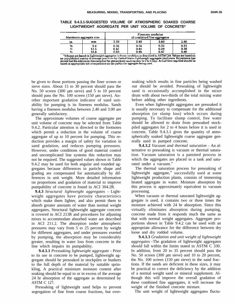
MEASURING, MIXING, TRANSPORTlNG, AND PLACING 304R-35
TABLE 9.4.3.1-SUGGESTED VOLUME OF ATMOSPHERIC SOAKED COARSELIGHTWEIGHT AGGREGATE PER UNIT VOLUME OF CONCRETE*
be given to those portions passing the finer screen orsieve sizes. About 15 to 30 percent should pass theNo. 50 screen (300 µm sieve) and 5 to 10 percentshould pass the No. 100 screen (150 µm sieve). An-other important gradation indicator of sand suit-ability for pumping is its fineness modulus. Sandshaving a fineness modulus between 2.40 and 3.00 aregenerally satisfactory.
The approximate volumes of coarse aggregate perunit volume of concrete may be selected from Table9.4.2. Particular attention is directed to the footnoteswhich permit a reduction in the volume of coarseaggregate of up to 10 percent for pumping. This re-duction provides a margin of safety for variation insand gradation, and reduces pumping pressures.However, under conditions of good material controland uncomplicated line systems this reduction maynot be required. The suggested values shown in Table9.4.2 may be used for both angular and rounded ag-gregates because differences in particle shape andgrading are compensated for automatically by dif-ferences in unit weight. More detailed informationon proportions and gradation of material to improvepumpability of concrete is found in ACI 304.2R.
9.4.3 Structural lightweight aggregates - Light-weight aggregates have porosity characteristicswhich make them lighter, and also permit them toabsorb greater amounts of water than normal weightaggregates, Structural lightweight aggregate concreteis covered in ACI 213R and procedures for adjustingmixes to accommodate absorbed water are describedin ACI 211.2. The absorption under atmosphericpressures may vary from 5 to 25 percent by weightfor different aggregates, and under pressures exertedby pumping, the absorption may be considerablygreater, resulting in water loss from concrete in theline which impairs its pumpability.
9.4.3.1 Presoaking lightweight aggregate - Priorto its use in concrete to be pumped, lightweight ag-gregate should be presoaked in stockpiles or bunkersto the full depth of the material by suitable sprin-kling, A practical minimum moisture content aftersoaking should be equal to or in excess of the average24 hr absorption of the aggregate as determined byASTM C 127.
Presoaking of lightweight sand helps to preventsegregation of fine from coarse fractions, but over-
soaking which results in fine particles being washedout should be avoided. Presoaking of lightweightsand is occasionally accomplished in the mixerdrum with about two-thirds of the total mixing waterbefore adding other ingredients.
Even when lightweight aggregates are presoaked itis usually necessary to compensate for the additionalabsorption (or slump loss) which occurs duringpumping. To facilitate slump control, free watershould be allowed to drain from presoaked stock-piled aggregates for 2 to 4 hours before it is used inconcrete. Table 9.4.3.1 gives the quantity of atmo-spherically soaked lightweight coarse aggregate gen-erally used in pumped concrete.
9.4.3.2 Vacuum and thermal saturation - An al-ternative to presoaking is vacuum or thermal satura-tion. Vacuum saturation is a patented process inwhich the aggregates are placed in a tank and satu-rated under a vacuum.40
The thermal saturation process for presoaking oflightweight aggregate,58 successfully used at somelightweight production plants, consists of immersingheated aggregate in water. Moisture absorption bythis process is approximately equivalent to vacuumprocessing.
When vacuum or thermal saturated lightweight ag-gregate is used, it contains two or three times themoisture achieved with 24 hr absorption. Since thisvirtually eliminates absorption during pumping,concrete made from it responds much the same asthat with normal weight aggregates. Aggregate pro-portions shown in Table 9.4.2 can be used with anappropriate allowance for the difference between dryloose and dry rodded volume.
9.4.3.3 Gradation and unit weight of lightweightaggregates -The gradation of lightweight aggregatesshould fall within the limits stated in ASTM C 330.In addition, from 20 to 35 percent should pass theNo. 50 screen (300 µm sieve) and 10 to 20 percent,the No. 100 screen (150 µm sieve) in the sand frac-tions. If the sands are deficient in these sizes, it maybe practical to correct the deficiency by the additionof a normal weight sand or mineral supplement. Al-though this will improve the overall gradation ofthese combined fine aggregates, it will increase theweight of the finished concrete mixture.
The unit weight of lightweight aggregates fluctu-
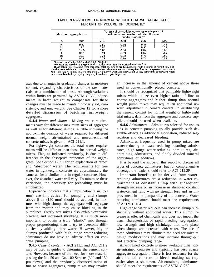
304R-36 MANUAL OF CONCRETE PRACTICE
TABLE 9.4.2-VOLUME OF NORMAL WEIGHT COARSE AGGREGATEPER UNIT OF VOLUME OF CONCRETE*
ates due to changes in gradation, changes in moisturecontent, expanding characteristics of the raw mate-rials, or a combination of these. Although variationswithin limits are permitted by ASTM C 330, adjust-ments in batch weight to compensate for thesechanges must be made to maintain proper yield, con-sistency, and unit weight. See Chapter 12 for a moredetailed discussion of batching lightweightaggregates.
9.4.4 Water and slump - Mixing water require-ments vary for different maximum sizes of aggregateas well as for different slumps. A table showing theapproximate quantity of water required for differentnormal weight air-entrained and non-air-entrainedconcrete mixes is given in ACI 211.1.
For lightweight concrete, the total water require-ments will be different than those for normal weightmixes. This, as indicated previously, is due to dif-ferences in the absorptive properties of the aggre-gates. See Section 12.2.1 for an explanation of “free”and “absorbed” water. The requirements for freewater in lightweight concrete are approximately thesame as for a similar mix in regular concrete. How-ever, the absorbed water will vary. To minimize thesevariations, the necessity for presoaking must beemphasized.
Experience indicates that slumps below 2 in. (50mm) are impractical for pumping and slumpsabove 6 in. (150 mm) should be avoided. In mix-tures with high slumps the aggregate will segregatefrom the mortar and may cause blocking in thepumplines. Overly wet mixes also exhibit excessivebleeding and increased shrinkage. It is much moreimportant to obtain a truly “plastic” mix throughproper proportioning, than to try to overcome diffi-culties by adding more water, However, higherslumps produced with high range water-reducingadmixtures do not have an adverse effect on con-crete pumping.
9.4.5 Cement content - ACI 211.1 and ACI 211.2may be used as guides to determine the cement con-tent. However, because of the need for more materialpassing the No. 50 and No. 100 Screens (300 and 150µm sieves) and the previously discussed ratios offine to coarse aggregates, pump mixes may involve
an increase in the amount of cement above thoseused in conventionally placed concrete.
It should be recognized that pumpable lightweightmixes which utilize even higher ratios of fine tocoarse aggregates and higher slump than normalweight pump mixes may require an additional up-ward adjustment in cement content. In establishingthe cement content for normal weight or lightweighttrial mixes, data from the aggregate and concrete sup-pliers should be used when available.
9.4.6 Admixtures - Admixtures selected for use asaids in concrete pumping usually provide such de-sirable effects as additional lubrication, reduced seg-regation and decreased bleeding.
Admixtures frequently used in pump mixes arewater-reducing or water-reducing retarding admix-tures, high-range water-reducing admixtures, air-entraining admixtures, and finely divided mineraladmixtures or additives.
It is beyond the scope of this report to discuss alltypes of concrete admixtures, but for comprehensivecoverage the reader should refer to ACI 212.2R.
Important benefits to be derived from water-reducing admixtures are a reduction in water re-quirement at constant slump with subsequentstrength increase or an increase in slump at constantwater-cement ratio with no strength loss and an im-provement in the pumpability of the concrete. Waterreducing admixtures should meet the requirementsof ASTM C 494.
High-range water reducers can increase slump sub-stantially without additional water. This slump in-crease is effected chemically and does not impart theusual characteristics of rapid bleeding, segregation,low strength and high shrinkage that take placewhen slumps are increased with water. The use ofthese admixtures may eliminate the need for mixturedesign modifications and may increase through-putand effective pumping range.
Air-entrained concrete is more workable than non-air-entrained concrete and typically has less coarseaggregate segregation. There is less tendency for theair-entrained concrete to bleed, making start-upeasier after a shutdown. Air-entraining admixturesshould meet the requirements of ASTM C 260.
MEASURING, MIXING, TRANSPORTING, AND PLACING 304R-37
Pumping does not materially affect the air contentof concrete; however, where air contents are requiredfor durability, ACI 201.2R states that they should betested at the point of placement in the structure.When durability is not a factor, an air content rangeof 3 to 5 percent gives best pumping results.
Finely divided mineral admixtures or additivesmay be used in pumped concrete to correct deficien-cies in sand gradation, reduce bleeding, and improveplasticity. Materials which could be included in thiscategory are:
1. Relatively chemically inert materials, such asground limestone, ground quartz, and hydrated lime;
2. Cementitious materials, such as granulatedblast-furnace slag, hydraulic lime, and slag cement;and
3. Pozzolans, such as fly ash, volcanic glass, someheat treated shales or clays, and diatomaceous earth(see ACI 212.1R and ACI 212.2R.).
9.4.7 Testing for pumpability - Since there is nouniversally accepted standard laboratory apparatusor equipment available to test the pumpability of amixture in the laboratory, 65 ,66 it is recommended thatmixtures be accepted for use on a pumping job basedon an actual test under field conditions. Testing amixture for pumpability involves a duplication ofanticipated job conditions including the batchingand mixing, the pump and operator, and the pipeand hose layouts. Prior use of a mixture on anotherjob may furnish evidence of pumpability but only tothe extent that all variable conditions are duplicated.
9.5-Field practices
The pump should be located as near to the placingarea as practical, and the delivery area must not im-pede the continuous supply of concrete. Pumplinesshould utilize the maximum amount of steel line andshould be laid out with a minimum of bends, nochanges in line size, and be firmly supported. If plac-ing booms or conveyors are not used, the setupshould include alternate lines and flexible pipe orhose to permit placing over a large area directly intothe work without rehandling. Careful handling of thepipeline during assembly, cleaning, and dismantlingwill aid in lowering line resistance by preventing theformation of rough surfaces and dents in pipesections.
When pumping downward 59 ft (15 m) or more, itis desirable to provide an air release valve at the mid-dle of the top bend to control vacuum or air buildup.When pumping upward it is desirable to have a valvenear the pump to prevent reverse flow of concreteduring the fitting of cleanup equipment or whenworking on the pump.
Direct communication should be maintained be-tween the pump operator and the concrete placingcrew. Good communication between the pump oper-ator and the batch plant is also desirable.
As a final check, the pump should be started and
cycled without concrete to be certain that all partsare operating properly. Pumped concrete moves as acylinder riding on a thin lubricating film of grout ormortar.41,62 To obtain this lubricating film at the be-ginning of the pumping operation, the first batchpumped through the line should be a properly pro-portioned grout or mortar. This material should beused for lubrication only and should not be used inconcrete placement. The same lubricating result maybe obtained by using concrete with a cement content100 to 200 lb (45 to 90 kg) higher than the concretespecified or the specified mix less the coarse aggre-gate. This procedure eliminates the need to disposeof excess lubricating grout. After provision is madefor grouting the line, the pump should be operatedslowly until the lines are completely full and theconcrete is moving steadily. Continuous pumping isdesirable. If the pump is stopped, it may be difficultor impossible to start movement of the concrete inthe line again. When a delay of pumping is antici-pated because of concrete delivery or other factors,the pump should be slowed down to maintain somemovement of the concrete in the line to avoid plug-ging. If, after a delay, concrete cannot be moved in theline, it will be necessary to clean out one line sec-tion, several sections, or the entire line and start over.
9.6-Field control
The locations at which concrete samples are takenis important. ASTM C 94 and C 685 require that sam-ples be taken from the discharge chute of the mixer.For pumped concrete, it may be desirable to sampleat both the point of delivery to the pump and thepoint of discharge from the line to perform com-parative testing to determine if any significantchanges in slump, air content, and other mix charac-teristics occur. If significant changes are found, ap-propriate allowances should be made for them.
The need for control of every operation has beenemphasized throughout this chapter. Good inspec-tion is probably the best assurance of a satisfactoryjob. ACI 311, SP-2, gives a detailed outline of inspec-tion to be performed in concrete construction. Goodmaterials and good equipment in the hands of com-petent and knowledgeable people will always pro-duce good results - t h i s is particularly true forpumped concrete.
CHAPTER l0-CONVEYING CONCRETE
10.1 -General considerations
Concrete belt conveyors are specially designed ormodified conveyors which transport fresh concretefrom a supply source to forms or other locations.Concrete placement by belt conveyor should be es-sentially a continuous operation. Maximum success

304R-38 MANUAL OF CONCRETE PRACTICE
requires a constant supply of properly mixed con-crete for charging the belt conveyor and a provisionfor moving the discharge point during placement sothe fresh concrete is deposited over the entire place-ment area without the need for rehandling or exces-sive vibration.
10.1.1 Concrete mixture proportioning - All struc-tural concrete can be handled satisfactorily by a con-crete belt conveyor. Extremes of slump, either below1 in. (25 mm) or above 7 in. (180 mm), tend to reducethe placing capacity of a conveyor significantly. Therollback tendencies of maximum-size aggregates(MSA) in excess of 4 in. (100 mm) greatly reduce thepermissible angle of elevation or decline. Maximumplacing efficiency and capacity with belt conveyorscan be obtained with a homogeneous concrete mixwhere the slump is controlled within a 2 to 4 in. (50to 100 mm) range. Belt speed becomes more criticalwhen the slump is outside this ideal range. Gener-ally, lower slumps require slower moving belts whilehigh slumps require faster moving belts.42
10.1.2 Concrete ribbon parameters - The charac-teristics of the ribbon of concrete on a conveyor beltare determined by the flowability of the concrete.Flowability determines the cross section which canbe efficiently carried on the belt. It also affects themaximum angle of incline or decline at which a beltconveyor can handle concrete (see ACI 304.4R).Many variables influence the flowability of concreteand make it difficult to predict the maximum per-missible angle of incline or decline. A good rule ofthumb is that a concrete belt conveyor can operatewith less than a 10 percent loss of horizontal capac-ity at an angle of 20 to 25 deg when equipped with asmooth belt and up to an angle of 30 to 35 deg whenthe belt is equipped with small straight corrugationsor ribs on the load-carrying surface.44 Concrete hasbeen successfully conveyed at greater angles withclose control of factors which affect flowability.
Concrete cannot be carried across the entire face ofa belt, The ribbon of concrete should be centered onthe belt with equal widths of clear belt or “edge dis-tance” (usually 1½ to 2 in. [40 to 50 mm]) between itand each edge of the belt. Failure to observe the“minimum edge distance” requirement will result inexcessive spilling and loss of large aggregate off theedge of the belt.
All concrete belt conveyors utilize belt support idl-ers which trough or cup the belt, enabling it to carrya deeper ribbon of concrete than would be possibleon a flat belt. Since the belt must flatten as it goesover the head pulley, the ribbon of concrete will tendto flow toward the belt edges in the area between thelast support idler and the head pulley. The action ofthe concrete in this area and in the area where it ischarged onto the belt will establish the maximumamount of any given concrete mixture which can behandled by a given conveyor.
As the angle of the conveyor (either incline or de-cline) is increased, the ribbon of concrete on the belt
becomes smaller. This reduction in ribbon size andthe effects of gravity increase the tendency for largerpieces of coarse aggregate to break loose from theribbon of concrete and roll away. The size, shape, andsurface characteristics of the coarse aggregate have animportant effect on this tendency. As the angle ofincline is increased the tendency of the concrete toflow or slide back also reduces belt capacity for agiven speed. The maximum angle at which a givenconcrete mixture can be conveyed is establishedwhen one of these factors becomes objectionable.
10.2-Conveyor requirements
Not all belt conveyors can successfully transportand place concrete. Concrete conveyors should bedesigned specifically to deal with the problems thatconcrete presents43 and adhere to the followingrequirements:
1. All components of the conveyor must be sized toaccommodate the weight of concrete. Normal weightconcrete is about 50 percent heavier than commonlyconveyed materials such as aggregates.
2. The conveyor itself, or at least the concrete dis-charge mechanism, must be capable of movementover the entire placement area without significantlyinterrupting or delaying placing. When placement inlifts is required for proper consolidation of the con-crete, the required movement is greatly increased.
3. Concrete belt conveyors must be able to stop,hold the concrete, and restart with the belt fullyloaded. This is necessary because placement cannotprogress faster than the concrete can be consolidatedand finished. This requirement is especially impor-tant when conveyors place concrete in wall and col-umn forms. The amount of concrete contained in theribbon on the belt is substantial compared to theamount of concrete which can be placed in suchforms. This makes it impractical to control filling ofthe form by controlling the charging of concrete ontothe conveyor.
4. Finally, conveyors must be designed to operatedependably under capacity loads. Once placementbegins, it should continue without any interruptionwhich could result in cold joints. The requirementsof reliability and dependability cannot be achievedsimply by making components larger and heavier be-cause this conflicts with the requirements of mobil-ity over the placement area.
10.2.1 Belt training - Concrete belt conveyorsmust be moved so frequently it is generally impossi-ble to assure that the supporting structure and beltidlers will always be level. Whenever a belt conveyoris not level, gravity will cause the belt to drift to thelow side. With longer conveyors this problem is moresevere. Relatively slight shifting of the belt on thesupporting idlers may result in concrete spillage orin damaging the belt by rubbing it against the sup-porting structure, so provisions must be made to
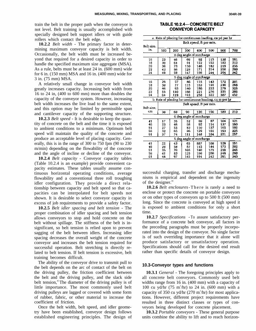
MEASURING, MIXING, TRANSPORTING, AND PLACING 304R-39
train the belt in the proper path when the conveyor isnot level. Belt training is usually accomplished withspecially designed belt support idlers or with guiderollers which contact the belt edge.
10.2.2 Belt width - The primary factor in deter-mining maximum conveyor capacity is belt width.Occasionally, the belt width must be increased be-yond that required for a desired capacity in order tohandle the specified maximum size aggregate (MSA).As a rule, belts must be at least 24 in. (600 mm) widefor 6 in. (150 mm) MSA and 16 in. (400 mm) wide for3 in. (75 mm) MSA.
A relatively small change in conveyor belt widthgreatly increases capacity. Increasing belt width from16 to 24 in, (400 to 600 mm) more than doubles thecapacity of the conveyor system. However, increasingbelt width increases the live load to the same extent,and this option may be limited by permissible spanand cantilever capacity of the supporting structure.
10.2.3 Belt speed - It is desirable to keep the quan-tity of concrete on the belt and the time it is exposedto ambient conditions to a minimum. Optimum beltspeed will maintain the quality of the concrete andproduce an acceptable level of placing capacity. Gen-erally, this is in the range of 300 to 750 fpm (90 to 230m/min) depending on the flowability of the concreteand the angle of incline or decline of the conveyor.
10.2.4 Belt capacity - Conveyor capacity tables(Table 10.2.4 is an example) provide convenient ca-
pacity estimates. These tables usually assume con-tinuous horizontal operating conditions, averageflowability and a conventional three roll troughingidler configuration. They provide a direct rela-tionship between capacity and belt speed so that ca-pacities can be interpolated for belt speeds notshown. It is desirable to select conveyor capacity inexcess of job requirements to provide a safety factor.10.2.5 Belt idler spacing and belt tension - Theproper combination of idler spacing and belt tensionallows conveyors to stop and hold concrete on thebelt without spillage. The stiffness of the belt is in-significant, so belt tension is relied upon to preventsagging of the belt between idlers. Increasing idlerspacing decreases the overall weight of the concreteconveyor and increases the belt tension required forsuccessful operation. Belt stretching is directly re-lated to belt tension. If belt tension is excessive, belttraining becomes difficult.
The ability of the conveyor drive to transmit pull tothe belt depends on the arc of contact of the belt onthe driving pulley, the friction coefficient betweenthe belt and the driving pulley, and the slack sidebelt tension,45 The diameter of the driving pulley is oflittle importance. The most commonly used beltdriving pulleys are lagged or covered with some formof rubber, fabric, or other material to increase thecoefficient of friction.
Once the belt width, belt speed, and idler geome-try have been established, conveyor design followsestablished engineering principles. The design of
successful charging, transfer and discharge mecha-nisms is empirical and dependent on the ingenuityof the designer.44
10.2.6 Belt enclosures - T h e r e is rarely a need toenclose or protect the concrete on portable conveyorsor on other types of conveyors up to 500 ft (500 mm)long. Since the concrete is conveyed at high speed itis exposed to ambient conditions for only a shorttime.
10.2.7 Specifications - To assure satisfactory per-formance of a concrete belt conveyor, all factors inthe preceding paragraphs must be properly incorpo-rated into the design of the conveyor. No single factoris of such overriding importance that it alone willproduce satisfactory or unsatisfactory operation.Specifications should call for the desired end resultrather than specific details of conveyor design.
10.3-Conveyor types and functions
10.3.1 General - The foregoing principles apply toall concrete belt conveyors. Commonly used beltwidths range from 16 in. (400 mm) with a capacity of100 cu yd/hr (75 m3/hr) to 24 in. (600 mm) with acapacity of 350 cu yd/hr (270 m3/hr) for most applica-tions. However, different project requirements haveresulted in three distinct classes or types of con-veyors being developed for concrete placement.
10.3.2 Portable conveyors - These general purposeunits combine the ability to lift and to reach horizon-

304R-40 MANUAL OF CONCRETE PRACTICE
tally with a limited spreading ability. General pur-pose conveyors are highly portable or maneuverableon the job and are either equipped with their ownundercarriage or are mounted on rough terrainhydraulic cranes to accomplish this maneuverability.The most common portable conveyors carry theirown gasoline or diesel power units and utilizehydraulic motor drive to the head pulley. Their sizeis limited by highway restrictions and the maximumlength is usually about 60 ft (18 m). This length es-tablishes a maximum horizontal reach of about 65 ft(20 m) with a spreading chute at the end up to 10 ft (3m) long and a discharge height, limited by the max-imum angle of elevation, of about 35 ft (10 m). Wheregreater lift or reach capability is required, hydrauliccranes are used to support the conveyor. Units capa-ble of reaching up to 140 ft (42 m) horizontally andup to 85 ft (26 m) vertically are available. Becauseportable conveyor set-up time is insignificant, theseunits are used for small placements like columns aswell as for larger placements in walls, footings, foun-dations, and slabs. Below grade placements are ac-complished using the cantilever reach of portableconveyors and an “elephant trunk” to control thedrop below grade. The only limit to the drop belowgrade is established by the ability of the conveyor tocarry the weight of the trunk.
10.3.3 Feeder or series conveyors - It is importantthat in these long reach applications the conveyorsautomatically start in sequence with the dischargeconveyor starting first and successive conveyors backto the charging point starting at intervals. This ar-rangement insures that each flight or unit of the sys-tem is operating at the proper belt speed beforeconcrete is discharged onto the belt.
The length of the conveyor units in a feeder trainare determined by the application. Short term jobslike overpass bridge decks are usually done with 30or 40 ft (9 or 12 m) long units which can be trans-ported over highways as completely assembledunits. Longer term projects generally use units 85 to100 ft (26 to 30 m) long which are relatively easilymoved by cranes. Where the job does not require fre-quent relocation, economic considerations dictatethe use of longer units even though their movementmay be more costly. The maximum length of suchlong units is generally determined by the horse-power requirements of the drive, with 450 to 500 ft(137 to 152 m) and 50 horsepower being the usualmaximums.
10.3.4 Spreading conveyors - These conveyors arespecifically designed for placing concrete and areusually radial or straight-line spreaders.
10.3.4.1 Radial spreaders - As the name im-plies, these conveyors employ a support whichswings the conveyor discharge end through an arc,up to 360 deg, while extending and retracting theplacing conveyor a substantial percentage of its over-all length. The support can be a moveable carriagewhich depends on outriggers to make a cantilever
reach possible. Shorter units can be operated manu-ally while longer conveyors, 40 ft (12 m) and over,require power to raise and lower and extend and re-tract the conveyor boom.
Radial spreaders have the advantage of relativelyquick setup time and the capability of reaching pastobstructions. They also create a minimum obstruc-tion or congestion in the placement area themselves.
10.3.4.2 Straight line spreaders - These sidedischarge conveyors span completely across theplacement area. By discharging concrete over theside of the belt with a traveling plow or diverter, theyplace a straight ribbon of concrete that is ideal formechanical finishing. They may be charged directlyfrom ready mix trucks, feeder conveyors or pumps,or by crane and bucket.
The diverter which removes concrete from the beltand discharges it over the side of the conveyor uti-lizes a wiper blade to remove the concrete from thebelt. The operation and adjustment of the wiperblade is more critical than on an end discharge con-veyor because it does not have gravity helping to re-move material from the belt. Provision must be madefor access to adjust the belt wiper or scraper on sidedischarge conveyors during the placement.
Some wear on the wiping strip is normal and asmall amount of grout may be carried past the diver-ter. A portion of this grout will be end discharged offthe conveyor belt and care should be taken that thismaterial does not form “grout puddles” in the con-crete placement.
10.3.5 Special conveyors - As long as belt speedsand widths are compatible, it is practical to combinedifferent types of conveyors to meet job require-ments.
A recent development has been the mounting ofconcrete belt conveyors on transporting equipmentsuch as truck mixers and on large concrete bucketsused in precast and prestressed plants. High capacitybelt conveyors are used in conjunction with slipformplacers for highway construction to transfer concretefrom points accessible to dump trucks to the place-ment area. While these conveyors do not fall com-pletely into any of the three types describedpreviously, they do operate within the limits andconditions which apply generally to all concrete beltconveyors.
10.4-Conveyor charging
Where ready-mixed concrete can be charged di-rectly from the truck mixer chute onto concrete beltconveyors, high capacities can be achieved by care-fully planning movement of the trucks to and fromthe charging hopper which is required to level outsurges in concrete flow and deliver a uniform ribbonof concrete to the belt with proper edge distance. Thebelt conveyor and truck delivery layout should beplanned so that one truck can be backing in and pre-paring to discharge while a second truck is discharg-
MEASURING, MIXING, TRANSPORTING, AND PLACING
ing. If conveyors are charged directly from a batchplant, a large surge hopper with an adjustable gatemust be used to receive the surge of material from themixer and provide a steady flow of concrete to thebelt conveyor.
10.5-Discharge control
Concrete is traveling at the same speed as the beltwhen it is discharged from a belt conveyor, It doesnot leave the belt as a stream or cohesive mass be-cause the inertia of the larger pieces of coarse aggre-gate tend to separate them from the stream and somemortar and fine aggregate will cling to the belt. Theenergy contained in the concrete mass must be dissi-pated or redirected by a discharge hopper to preventsegregation. The turbulence created by this dissipa-tion of energy has a remixing action in properly de-signed hoppers. As the angle of incline or decline ofa concrete belt conveyor is changed, the angle of thedischarge hopper attached to it is also changed.While most discharge hoppers function properly ifslightly tilted, they will plug and delay operation if acondition results where gravity will not pull the con-crete through the hopper.
Every end-discharge conveyor must be equippedwith a belt wiper or scraper to limit mortar loss.42
The wiper or scraper should be positioned so that themortar is directed into the discharge hopper for re-mixing. Belt wipers depend on moisture in the con-crete for lubrication and cooling. Dry belts shouldnot be operated unless the belt wipers are removed.
Properly designed discharge hoppers, chutes, ortremies will eliminate concrete segregation problemsat transfer and discharge locations. Job conditionsfrequently limit the size of such accessories, so nu-merous designs have been developed through trialand error which produce satisfactory results with thespecific concrete mixture being placed. A generalrule for the minimum length of a downpipe is 24 in.(600 mm). This length has been found to produceacceptable results in most cases; however, thisshould not preclude the use of other designs whichdemonstrate satisfactory performance under jobconditions.
As the placing progresses, fresh concrete shouldalways be discharged onto or against concrete that isalready in place so there will be no opportunity forobjectionable rock pockets to be formed. A vibratorshould be available for continuous operation wherethe concrete is dropping to prevent stacking and seg-regation of the large pieces of coarse aggregate. Thisvibration is intended to only provide minor levelingaction and the vibrators should not be inserted within2 ft (600 mm) of any leading (unconfined) edge of theconcrete. The point of delivery must be moved fre-quently so the concrete does not have to be rehandledor moved laterally by vibration, Since belt conveyorplacing rates are usually higher than can be achievedwith buckets, a larger number of vibrators may be
required for consolidation of the concrete. Vibrationat the delivery point and along the advancing edge ofthe concrete will cause the concrete to envelope rein-forcing steel without significant separation.
10.6-Maintenance
Some conveyor maintenance may be necessaryduring concrete placement on large volume projects.This is generally limited to three items.
10.6.1 Belt tension adjustment - All conveyor belt-ing will stretch to some degree during concrete plac-ing. Since transferring power from the drive pulley tothe belt depends on return belt tension (i.e., snub-bing of the belt around the drive pulley) adequatebelt tension must be maintained at all times whileconcrete is being placed. All concrete conveyorsmust have a provision for increasing belt tension inthe event the drive pulley begins slipping inside thebelt during concrete placing.
10.6.2 Belt wiper adjustment - The belt wiper is inconstant contact with the belt and abrasive concrete,and wear of the belt wiper is normal. Concrete con-veyors should have provisions to compensate or ad-just for this wear so that efficient belt wiping ismaintained. Belt wipers must be replaced when theyhave worn so much that adjustment will not producesatisfactory belt cleaning.
10.6.3 Equipment cleanup - No equipment oper-ates well or for a long time if it is not kept clean. Thisis especially true of belt conveyors. Any spilled con-crete should be cleaned off the conveyor before it canharden. Particular care should be taken to keep thecharging hopper, discharge hopper, belt wiper, andreturn idlers clean and free of concrete buildup. Ex-cept for the belt, it is desirable to coat all parts of theconveyor with form oil to expedite cleanup.
CHAPTER 11-HEAVYWEIGHT ANDRADIATION SHIELDING CONCRETE
11.1-General considerations
The procedures for measuring, mixing, transport-ing and placing heavyweight and radiation shieldingconcrete are similar to those used in conventionalconcrete construction. However, special expertiseand thorough planning are necessary for the suc-cessful completion of this type of concrete work.47
Normal weight concrete is generally specified forradiation shielding when space is available. However,when space is limited, the thickness of these shieldscan be reduced by utilizing both natural and syntheticheavyweight aggregates. Natural mineral aggregatesand synthetic aggregate can produce concrete havinga typical density as high as 240 lb/cu ft (3840 kg/m3)and 340 lb/cu ft (5450 kg/m3), respectively. Heavy-weight concrete not only has a higher density, but alsomore desirable attenuation properties.
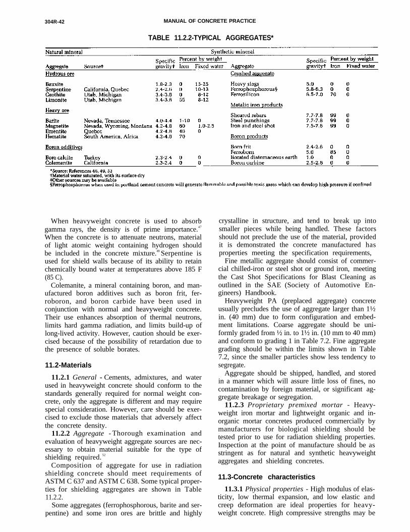
304R-42 MANUAL OF CONCRETE PRACTICE
TABLE 11.2.2-TYPICAL AGGREGATES*
When heavyweight concrete is used to absorbgamma rays, the density is of prime importance.47
When the concrete is to attenuate neutrons, materialof light atomic weight containing hydrogen shouldbe included in the concrete mixture.48 Serpentine isused for shield walls because of its ability to retainchemically bound water at temperatures above 185 F(85 C).
Colemanite, a mineral containing boron, and man-ufactured boron additives such as boron frit, fer-roboron, and boron carbide have been used inconjunction with normal and heavyweight concrete.Their use enhances absorption of thermal neutrons,limits hard gamma radiation, and limits build-up oflong-lived activity. However, caution should be exer-cised because of the possibility of retardation due tothe presence of soluble borates.
11.2-Materials
11.2.1 General - Cements, admixtures, and waterused in heavyweight concrete should conform to thestandards generally required for normal weight con-crete, only the aggregate is different and may requirespecial consideration. However, care should be exer-cised to exclude those materials that adversely affectthe concrete density.
11.2.2 Aggregate - Thorough examination andevaluation of heavyweight aggregate sources are nec-essary to obtain material suitable for the type ofshielding required. 52
Composition of aggregate for use in radiationshielding concrete should meet requirements ofASTM C 637 and ASTM C 638. Some typical proper-ties for shielding aggregates are shown in Table11.2.2.
Some aggregates (ferrophosphorous, barite and ser-pentine) and some iron ores are brittle and highly
crystalline in structure, and tend to break up intosmaller pieces while being handled. These factorsshould not preclude the use of the material, providedit is demonstrated the concrete manufactured hasproperties meeting the specification requirements,
Fine metallic aggregate should consist of commer-cial chilled-iron or steel shot or ground iron, meetingthe Cast Shot Specifications for Blast Cleaning asoutlined in the SAE (Society of Automotive En-gineers) Handbook.
Heavyweight PA (preplaced aggregate) concreteusually precludes the use of aggregate larger than 1½in. (40 mm) due to form configuration and embed-ment limitations. Coarse aggregate should be uni-formly graded from ½ in. to 1½ in. (10 mm to 40 mm)and conform to grading 1 in Table 7.2. Fine aggregategrading should be within the limits shown in Table7.2, since the smaller particles show less tendency tosegregate.
Aggregate should be shipped, handled, and storedin a manner which will assure little loss of fines, nocontamination by foreign material, or significant ag-gregate breakage or segregation.
11.2.3 Proprietary premixed mortar - Heavy-weight iron mortar and lightweight organic and in-organic mortar concretes produced commercially bymanufacturers for biological shielding should betested prior to use for radiation shielding properties.Inspection at the point of manufacture should be asstringent as for natural and synthetic heavyweightaggregates and shielding concretes.
11.3-Concrete characteristics
11.3.1 Physical properties - High modulus of elas-ticity, low thermal expansion, and low elastic andcreep deformation are ideal properties for heavy-weight concrete. High compressive strengths may be

MEASURING, MIXING, TRANSPORTING, AND PLACING 304R-43
required if heavyweight concrete is to be subjected tohigh stress levels. Heavyweight concrete with highcement contents and low water-cement ratios mayexhibit increased creep and shrinkage, and in a mas-sive concrete placement could generate high tem-peratures at early ages, causing undesirable localizedcracking from the thermally induced stresses. Whenstructural considerations require this cracking poten-tial to be eliminated, it will be necessary to utilizeappropriate temperature control measures whichcould include precooling or postcooling the con-crete, or both (ACI 207.2R).
11.3.2 Mixture proportioning - Procedures out-lined in Appendix 4 of ACI 211.1 should be used forconcrete proportioning. Conventionally placedheavyweight concrete should be proportioned to pro-vide the desired compressive strength and density aswell as adequate workability. Also, the chemical con-stituents and fixed water content of the resulting mix-ture must provide satisfactory shielding properties.50
Typical proportions for heavyweight, conventionallyplaced concrete, PA concrete, and grout mixes areshown in Table 11.3.2.
11.4-Mixing equipment
Standard mixing equipment is generally used tomix heavyweight concrete, but care should be taken
not to overload the equipment. In general, theamount of heavyweight concrete mixed should beequivalent to the mixture weight of normal weightconcrete rather than the volume capacity of the mix-ing equipment. Heavyweight concrete should be agi-tated when transported from the mixing plant to thepoint of placement to prevent segregation, consolida-tion, and packing.
11.5-Formwork
Formwork should conform to ACI 347. The formdesigner should be aware that formwork for conven-tionally placed heavyweight concrete must neces-sarily be stronger than comparable formwork forordinary concrete by reason of increased concretedensity.
Typical structures require a complex shape andmay contain many penetrations through the form-work. The strutting and bracing system must be care-fully designed to avoid unintentionally placing aload on penetrating members and to insure precisealignment of external fixtures corresponding to thesepenetrations. Consideration should be given to thepossible advantages of using permanent steel forms.
Steel penetrations are often precisely machinedand fabricated assemblies which may be subject todelays in delivery. It may be prudent to allow for
304R-44 MANUAL OF CONCRETE PRACTICE
such delays by providing for blockouts to receivethese penetrations. Blockouts should be providedwith normal bends or step configuration to reducethe possibility of radiation shine or leakage. Thebasic structure may then be completed around theblockouts. After the items to be embedded areplaced, the blockouts are filled with heavyweightgrout. Precautions should be taken to insure that allpenetrations and blockouts are tightly grouted with anonshrink grout of appropriate density.
11.6-Placement
11.6.1 Conventional method - Placement of con-ventionally mixed, heavyweight concrete is subjectto the same considerations of quality control as nor-mal weight concrete, except that it is far more sus-ceptible to variations in quality due to improperhandling.
The placement of heavyweight concrete dictatesthe strictest observation of good placement practice.Regular concrete placing techniques can be used, in-cluding pumping. Heavyweight concrete should beplaced as close as possible to its final position in theforms with a minimum of vibration to prevent segre-gation. The use of long, rigid chutes or drop pipesshould be avoided. Where concrete must be placedin narrow forms or through restricted areas, a short,flexible type drop chute which tends to collapse andrestrict the fall should be employed. Layers shouldbe limited to a maximum 12 in. (300 mm) thickness.
Consolidation procedures should conform to ACI309, Chapter 14. In heavyweight concrete, vibratorshave a smaller effective area or radius of action;therefore greater care must be exercised to insure thatthe concrete is properly consolidated.
Vibration and revibration for removing entrappedair and to establish aggregate to aggregate contactmay cause an excess amount of grout to collect on thetop of lift surfaces. 51 This grout should be removedfrom the lift surface while the concrete is still in afresh state.
11.6.2 Preplaced aggregate method - Precautionsfor placing heavyweight PA concretes are cited inChapter 7. Placing grout for heavyweight PA concreterequires extreme care because of a greater tendencyfor segregation and line blockages. Therefore, amplepreparations should be made for rapid clearing ofgrout hoses and pipes. Standby equipment should beprovided, and a trial run is recommended prior toactual operation.
11.7-Quality control
11.7.1 Samples and testing - All heavyweight andradiation shielding concrete materials should besampled and tested prior to and during constructionto insure conformance with applicable standardsand specifications. Guidance presented in ACI stan-dards and reports, as well as previous experience
with the same materials, will determine the fre-quency of testing.
The complexity of structures in which heavy-weight concrete is placed usually precludes the pos-sibility of taking test cores. It is, therefore, of theutmost importance that a thorough quality controlprogram be established prior to the start of construc-tion and maintained throughout construction.
11.7.2 Control tests - The quality of the concreteproduced and its constituent materials should becontrolled by an established program of samplingand testing in accordance with appropriate ASTMtest methods. The limits of rejection for heavyweightconcrete should be established in the constructionspecifications and conform to the design parametersof the structures involved. Prior to wasting expensiveheavyweight concrete, the engineer should be noti-fied so he can evaluate the severity of any nonconfor-mance problem.
Heavyweight PA concrete is adaptable to the use ofsophisticated and exacting quality control tests, theextent of control exercised depending on the com-plexity and importance of the project.
Tests of materials, grouts, and compressivestrength of heavyweight PA concrete should be thesame as those given in Chapter 7.
11.7.3 Inspection - The inspection of heavyweightconcrete should be in accordance with applicablestandards and project specifications.
Other than special modifications required by highunit weight, those inspection items emphasized asimportant in ACI 311.4R should be followed forheavyweight concrete as well.
CHAPTER 12-LIGHTWEIGHTSTRUCTURAL CONCRETE
12.1 -General considerations
Measuring, mixing, transporting and placing light-weight concrete is similar in many respects to com-parable procedures for normal weight concrete.However, there are certain differences, especially inproportioning and batching procedures, that shouldbe considered in order to produce a finished productof comparable quality. The weight and absorptiveproperties of lightweight aggregates are different andmust be properly considered. This chapter deals pri-marily with batching methods for the coarse light-weight aggregates to correct for changes in weightand moisture content to ensure proper yield.61 It alsocovers batching of lightweight fine aggregates using amodification of the method used for coarse light-weight aggregates. 55,56 These batching methods havebeen coordinated with the basic principles set forthin ACI 211.2 and other batching methods which pro-duce satisfactory results are reported in ACI 211.2. It

MEASURING, MIXING, TRANSPORTING, AND PLACING 304R-45
is necessary that the user refer to this document toget an overall view of the methods available forbatching lightweight aggregate as this material is notduplicated here.
12.2-Measuring and batching
12.2.1 Free water and absorbed water - One of thefirst considerations in batching lightweight concretemixtures is a proper understanding of the water usedin the mixture. 60 The total water used per unit vol-ume is divided into two components. One part is thewater absorbed by the aggregates, while the other issimilar to that in normal weight aggregate concreteand is classified as free water. Free water controls theslump and when mixed with a given quantity of ce-ment establishes the strength of the paste, as for anyconcrete mixture. The amount and weight of ab-sorbed water will vary with different lightweight ma-terials ,58,59 presoaking and mixing times. Absorbedwater does not change the volume of the aggregates orconcrete because it is inside the aggregate. Most im-portantly, absorbed water does not effect the water-cement ratio or the slump of the concrete.
12.2.2 Unit weight variations - The unit weight oflightweight aggregate varies depending on the rawmaterials used and the size of the aggregate. Smallerparticles usually have higher unit weights thanlarger particles. Unit weights also vary due tochanges in absorption or moisture content. If thelightweight aggregates are batched by weight withoutadjusting for these variations in unit weight, prob-lems of over or under yield of the concrete can result.
The dry, loose unit weight of aggregate dependsprimarily on its specific gravity, and on the grading,and shape of the particles. Angular crushed aggre-gates have more voids or unfilled spaces between theaggregate particles than rounded or sphericallyshaped pieces. 63,64 Poorly graded aggregate (i.e., allone size) generally has more voids than a uniformlygraded material which has enough smaller pieces tofit into the voids between the larger particles.
Numerous routine tests of both natural and light-weight aggregates show an amazingly close correla-tion of the void content for specific products beingproduced by a given plant over a long period. Eachproduction facility has its own characteristic voidcontent values for each size aggregate being pro-duced and this information can usually be obtainedfrom the source.
The absolute volume of a specific lightweightcoarse aggregate is the volume of material remainingafter the volume of voids has been subtracted. Theabsolute volume, or the displaced volume in the con-crete, for a given lightweight material remains thesame even though its density or its moisture contentchanges.
The proper usage of these basic principles makes itpossible to batch and deliver lightweight concrete atthe proper slump and yield for any job.
12.2.3 Volume-weight batching coarse aggregate-To avoid problems with yield of concrete, it is neces-sary to maintain the same absolute volumes of light-weight aggregates in each batch of concrete byadjusting the batch weights to compensate forchanges in unit weights. Standard unit weight testson the lightweight aggregates, made frequently dur-ing batching operations may be used to adjust batchweights to reflect any changes that may occur in unitweights. This practice may be rather time consumingin a busy production facility and a volume-weightbatching system has been developed and used insome areas as an alternate method. Either methodproduces satisfactory results. The principal differ-ence between the systems reported here and that re-ported in ACI 211.2 is that the volume-weightmethod provides automatic yield adjustments forevery single batch of lightweight concrete withoutthe need for determining specific gravity factors ofstructural lightweight aggregate.
12.2.3.1 Calibrating the weighing hopper - Thevolume-weight system can be set up for virtually anybatching system that employs a hopper or bin forweighing materials. The first operation is to deter-mine the volume of this weighing hopper.
When the discharge gate in the overhead bin con-taining the lightweight coarse aggregate is opened,the material will flow into the weighing hopper untilit builds up to the level of the discharge gate. Someplants may be slightly different than others but suit-able modifications can be made in the overhead binsor in the weighing hopper or both to allow the weigh-ing hopper to be filled to a prescribed level eachtime.
The volume of lightweight aggregate in this filledweighing hopper can be calibrated for most batchingplants in the following manner. The total weight ofthe material (either dry or containing absorbedwater) in the filled hopper can be read directly fromthe scales. The hopper is then discharged into adump truck and the unit weight of three or four sam-ples of loose material are determined in a suitablecontainer. The total hopper weight divided by theaverage unit weight will give the total volume of thematerial in the weighing hopper in cubic feet or incubic meters. As an example, if the net weight of thefilled hopper is 4650 lb (2100 kg) and the averageunit weight of the material in it is 48.2 lb/cu ft (772kg/m3), the volume is simply 4650/48.2 = 96.5 cu ft(2210/772 = 2.73 m3). This calibration procedureshould be performed about three times to insurevalid measurements. A new calibration might benecessary if the source of lightweight aggregate ischanged, since the new material may have a differentangle of repose which could alter the overall volumein the weighing hopper. If no major changes occur inthe lightweight aggregates, one calibration will suf-fice for several months or until some major changehas taken place in the materials.
The calibrated weighing hopper can be used as a
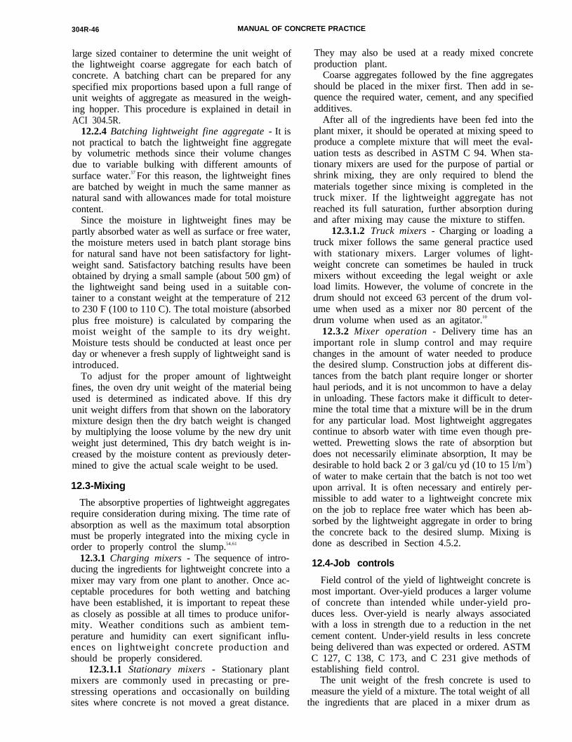
304R-46 MANUAL OF CONCRETE PRACTICE
t
large sized container to determine the unit weight ofthe lightweight coarse aggregate for each batch ofconcrete. A batching chart can be prepared for anyspecified mix proportions based upon a full range ofunit weights of aggregate as measured in the weigh-ing hopper. This procedure is explained in detail inACI 304.5R.
12.2.4 Batching lightweight fine aggregate - It isnot practical to batch the lightweight fine aggregateby volumetric methods since their volume changesdue to variable bulking with different amounts ofsurface water.57 For this reason, the lightweight finesare batched by weight in much the same manner asnatural sand with allowances made for total moisturecontent.
Since the moisture in lightweight fines may bepartly absorbed water as well as surface or free water,the moisture meters used in batch plant storage binsfor natural sand have not been satisfactory for light-weight sand. Satisfactory batching results have beenobtained by drying a small sample (about 500 gm) ofthe lightweight sand being used in a suitable con-tainer to a constant weight at the temperature of 212to 230 F (100 to 110 C). The total moisture (absorbedplus free moisture) is calculated by comparing themoist weight of the sample to its dry weight.Moisture tests should be conducted at least once perday or whenever a fresh supply of lightweight sand isintroduced.
To adjust for the proper amount of lightweightfines, the oven dry unit weight of the material beingused is determined as indicated above. If this dryunit weight differs from that shown on the laboratorymixture design then the dry batch weight is changedby multiplying the loose volume by the new dry unitweight just determined, This dry batch weight is in-creased by the moisture content as previously deter-mined to give the actual scale weight to be used.
12.3-Mixing
The absorptive properties of lightweight aggregatesrequire consideration during mixing. The time rate ofabsorption as well as the maximum total absorptionmust be properly integrated into the mixing cycle inorder to properly control the slump.54,61
12.3.1 Charging mixers - The sequence of intro-ducing the ingredients for lightweight concrete into amixer may vary from one plant to another. Once ac-ceptable procedures for both wetting and batchinghave been established, it is important to repeat theseas closely as possible at all times to produce unifor-mity. Weather conditions such as ambient tem-perature and humidity can exert significant influ-ences on lightweight concrete production andshould be properly considered.
12.3.1.1 Stationary mixers - Stationary plantmixers are commonly used in precasting or pre-stressing operations and occasionally on buildingsites where concrete is not moved a great distance.
They may also be used at a ready mixed concreteproduction plant.
Coarse aggregates followed by the fine aggregatesshould be placed in the mixer first. Then add in se-quence the required water, cement, and any specifiedadditives.
After all of the ingredients have been fed into theplant mixer, it should be operated at mixing speed toproduce a complete mixture that will meet the eval-uation tests as described in ASTM C 94. When sta-tionary mixers are used for the purpose of partial orshrink mixing, they are only required to blend thematerials together since mixing is completed in thetruck mixer. If the lightweight aggregate has notreached its full saturation, further absorption duringand after mixing may cause the mixture to stiffen.
12.3.1.2 Truck mixers - Charging or loading atruck mixer follows the same general practice usedwith stationary mixers. Larger volumes of light-weight concrete can sometimes be hauled in truckmixers without exceeding the legal weight or axleload limits. However, the volume of concrete in thedrum should not exceed 63 percent of the drum vol-ume when used as a mixer nor 80 percent of thedrum volume when used as an agitator.10
12.3.2 Mixer operation - Delivery time has animportant role in slump control and may requirechanges in the amount of water needed to producethe desired slump. Construction jobs at different dis-tances from the batch plant require longer or shorterhaul periods, and it is not uncommon to have a delayin unloading. These factors make it difficult to deter-mine the total time that a mixture will be in the drumfor any particular load. Most lightweight aggregatescontinue to absorb water with time even though pre-wetted. Prewetting slows the rate of absorption butdoes not necessarily eliminate absorption, It may bedesirable to hold back 2 or 3 gal/cu yd (10 to 15 l/m3)of water to make certain that the batch is not too wetupon arrival. It is often necessary and entirely per-missible to add water to a lightweight concrete mixon the job to replace free water which has been ab-sorbed by the lightweight aggregate in order to bringthe concrete back to the desired slump. Mixing isdone as described in Section 4.5.2.
12.4-Job controls
Field control of the yield of lightweight concrete ismost important. Over-yield produces a larger volumeof concrete than intended while under-yield pro-duces less. Over-yield is nearly always associatedwith a loss in strength due to a reduction in the netcement content. Under-yield results in less concretebeing delivered than was expected or ordered. ASTMC 127, C 138, C 173, and C 231 give methods ofestablishing field control.
The unit weight of the fresh concrete is used tomeasure the yield of a mixture. The total weight of allhe ingredients that are placed in a mixer drum as

MEASURING, MIXING, TRANSPORTING, AND PLACING 304R-47
given on the delivery ticket are added, or the entiretruck may be weighed before and after discharging.The unit weight of concrete divided into the weightof all the ingredients will give the total volume ofconcrete in the mixer drum. When the calculatedvolume is more than 2 percent above or below thevolume shown on the delivery ticket an adjustmentis required.
If the change in yield is due to entrained aircontent, then an adjustment in the amount of air-entraining admixture may correct this condition.
If the unit weight measured in the field is greaterthan the wet unit weight shown for the mixture de-sign this would indicate an under-yield, converselyif the weight is less, an over-yield may occur. Whenthere have been no appreciable changes in theweights of the lightweight aggregates themselves, inall probability the differences in yield can be at-tributed to an incorrect amount or an incorrect abso-lute volume of lightweight aggregates. In this casesteps should be taken at the batch plant to correct theabsolute volume of lightweight aggregates used in theconcrete as it is being batched.
C H A P T E R 1 3 - R E F E R E N C E S
13.1-Recommended references
The documents of the various standards-producingorganizations referred to in this document are listedbelow with their serial designation.
American Association of State Highway and TransportationOfficials
Guide Specifications for HighwayConstruction
American Concrete Institute
201.2R207.1R207.2R
211.1
211.2
212.2R
221R
223
224R
302.1R
304.2R
304.3R
Guide to Durable ConcreteMass ConcreteEffect of Restraint, Volume Change,and Reinforcement on Cracking ofMassive ConcreteRecommended Practice for Select-ing Proportions for Normal andHeavyweight ConcreteRecommended Practice for Select-ing Proportions for StructuralLightweight ConcreteGuide for Use of Admixtures inConcreteGuide for Use of Normal WeightAggregates in ConcreteStandard Practice for the Use ofShrinkage Compensating ConcreteControl of Cracking in ConcreteStructuresGuide for Concrete Floor and SlabConstructionPlacing Concrete by PumpingMethodsHigh Density Concrete: Measuring,Mixing, Transporting and Placing
304.4R
305R306R308
309
311.4R316R
318
347R
506R
ASTM
C 33
C 94
C 127
C 138
C 143
C 150C 172
C 173
C 231
C 260
C 330
C 494
C 595
C 637
C 638
C 685
C 845
C 937
C 938
C 939
C 943
Placing Concrete with Belt Con-veyorsHot Weather ConcretingCold Weather ConcretingStandard Practice for Curing Con-creteRecommended Practice for Consol-idation of ConcreteGuide for Concrete InspectionRecommended Practice for Con-struction of Concrete Pavementsand Concrete BasesBuilding Code Requirements forReinforced ConcreteRecommended Practice for Con-crete FormworkGuide for Shotcreting
Specifications for Concrete Aggre-gatesSpecification for Ready MixedConcreteTest Method for Specific Gravityand Absorption of Coarse Aggre-gatesTest Method for Unit Weight, Yieldand Air Content (Gravimetric) ofConcreteTest Method for Slump of PortlandCement ConcreteSpecification for Portland CementMethod of Sampling FreshlyMixed ConcreteTest Method for Air Content ofFreshly Mixed Concrete by theVolumetric MethodTest Method for Air Content ofFreshly Mixed Concrete by thePressure MethodSpecification for Air-EntrainingAdmixtures for ConcreteSpecification for Lightweight Ag-gregates for Structural ConcreteSpecification for Chemical Admix-tures for ConcreteSpecification for Blended Hydrau-lic CementsSpecification for Aggregates forRadiation-Shielding ConcreteDescriptive Nomenclature of Con-stituents for Radiation-ShieldingConcreteSpecification for Concrete Made byVolumetric Batching and Continu-ous MixingSpecification for Expansive Hy-draulic CementSpecification for Grout Fluidifierfor Preplaced-Aggregate ConcretePractice for Proportioning GroupMixtures for Preplaced-AggregateConcreteTest Method for Flow of Grout forPreplaced-Aggregate ConcretePractice for Making Test Cylindersand Prisms for DeterminingStrength and Density of Preplaced-Aggregate Concrete in the Labora-tory
304R-48 MANUAL OF CONCRETE PRACTICE
C 953
D 75D 2419
Test Method for Time of Setting ofGrouts for Preplaced-AggregateConcrete in the LaboratoryPractices for Sampling AggregatesTest Method for Sand EquivalentValue of Soils and Fine Aggregate
U.S. Army Corps of Engineers
CRD-C55
CW-03305
EM 1110-2-2000
Handbook for Concrete and Ce-ment, Test Method for ConcreteMixer PerformanceCivil Works Construction GuideSpecification for ConcreteStandard Practice for Concrete
The above publications may be obtained from thefollowing organizations:
American Association of State Highway and TransportationOfficials444 N. Capitol St. NWSuite 225Washington, DC 20001
American Concrete InstitutePO Box 19150Detroit, MI 48219
ASTM1916 Race St.Philadelphia, PA 19103
U.S. Army Corps of EngineersWaterways Experiment StationPO Box 631Vicksburg, MS 39180
13.2-Cited references1. Significance of Tests and Properties of Concrete and Con-
crete-Making Materials, STP-169B, ASTM, Philadelphia, 1978,pp. 539-763.
2. Concrete Manual, 8th Edition, U.S. Bureau of Reclamation,Denver, 1975 (Revised 1981), 627 pp.
3. Tynes, W. O., “Influence of Fine Aggregate Grading on Prop-erties of Concrete,” Technical Report No. 6-544, U.S. Army En-gineer Waterways Experiment Station, Vicksburg, Oct. 1962, 25pp.
4. Van Alstine, C. B., “Mixing Water Control by Use of aMoisture Meter,” ACI JOURNAL, Proceedings V. 52, No. 3, Nov.1955, pp 341-348. Also, Discussion, Part 2, Dec. 1956, p. 1209.
5. Lovern, J. D., “Important Variables Affecting Moisture Con-trol,” Modern Concrete, V. 30, No. 4, Aug. 1966, pp. 44-46.
6. “A Study of Mixing Performance of Large Central Plant Con-crete Mixers ,” U.S. Department of Commerce, Bureau of PublicRoads, Washington, DC., July 1966.
7. Bozarth, E. M., “Case Study of Influences of Imbalances inCharging of Cement and Water on Mixing Performance of an EightCubic Yard Central Plant Mixer,” U.S. Bureau of Public Roads,Washington, D.C., July 1967.
8. “Concrete Plant Standards of the Concrete Plant Manufactur-ers Bureau,” Concrete Plant Manufacturers Bureau, Silver Spring,Jan. 1983, 11 pp.
9. “Recommended Guide Specifications for Batching Equip-ment and Control Systems in Concrete Batch Plants,” PublicationNo. 102, Concrete Plant Manufacturers Bureau, Silver Spring,1977, 11 pp.
10. “Mixing Concrete in a Truck Mixer,” Publication No. 148,National Ready Mixed Concrete Association, Silver Spring, 1975,24 pp.
11. “Concrete Plant Mixer Standards of the Plant Mixer Manu-facturers Division, Concrete Plant Manufacturers Bureau,” 5th Re-
vision, Concrete Plant Manufacturers Bureau, Silver Spring, July1977, 4 pp.
12. “Recommended Practice for Measuring the Uniformity ofConcrete Produced in Truck Mixers,” Publication No. 117, Na-tional Ready Mixed Concrete Association, Silver Spring, 1965, 10pp.
13. “Superplasticizing Admixtures in Concrete,” PublicationNo. 45.030, Cement and Concrete Association, Wexham Springs,Jan. 1976, 32 pp.
14. "Recommended Practice for Use of High-Range Water Re-ducing Admixtures in Precast Prestressed Concrete Operations,”Journal, Prestressed Concrete Institute, V. 26, No, 5, Sept.-Oct.1981, pp. 28-48.
15. "Truck Mixer and Agitator Standards of the Truck MixerManufacturers Bureau,” 19th Edition, Truck Mixer ManufacturersBureau, Silver Spring.
16. CRSI Handbook, 5th Edition, Concrete Reinforcing SteelInstitute, Schaumburg, 1982.
17. Tynes, W. O., “Investigation of Methods of Preparing Hori-zontal Construction Joints in Concrete,” Technical Report No.6-518, U.S. Army Engineer Waterways Experiment Station,Vicksburg, July 1959, 19 pp.
18. Tynes, W. O., “Investigation of Methods of Preparing Hori-zontal Construction Joints in Concrete-Report 2, Tests of Joints ofLarge Blocks,” Technical Report No. 6-518, U.S. Army EngineerWaterways Experiment Station, Vicksburg, July 1963, 19 pp.
19. Davis, R. E., Jr., and Haltenhoff, C. E., “Mackinac Bridge PierConstruction,” ACI JOURNAL, Proceedings V. 53, No. 6, Dec.1956, pp. 581-596.
20. Davis, R. E., Jr.; Johnson, G. D.; and Wendell, G. E., “KemanoPenstock Tunnel Liner Backfilled with Prepakt Concrete,” ACIJOURNAL, Proceedings V. 52, No. 3, Nov. 1955, pp. 287-308.
21. “Investigation of the Suitability of Prepakt for Mass andReinforced Concrete Structure,” Technical Memorandum No.6-330, U.S. Army Engineer Waterways Experiment Station,Vicksburg, Aug. 1954, 44 pp.
22. King, John C., “Special Concretes and Mortars,” Handbookof Heavy Construction, 2nd Edition, McGraw-Hill Book Co., NewYork, 1971, pp. 22-l-22-30.
23, Davis, Harold S., “High Density Concrete for ShieldingAtomic Energy Plants,” ACI JOURNAL, Proceedings V. 54, No, 11,May 1958, pp. 965-978.
24. Davis, Raymond E., “Prepakt Method of Concrete Repair,”ACI JOURNAL, Proceedings V. 57. No. 2, Aug. 1960, pp. 155-172.
25. Gerwick, Ben C., “Placement of Tremie Concrete,” Sym-posium on Concrete in Aqueous Environments, SP-8, AmericanConcrete Institute, Detroit, 1964, pp. 9-20.
26. Gerwick, B. C.; Holland, T. C.; and Komendant, G. J.,“Tremie Concrete for Bridge Piers and Other Massive UnderwaterPlacements,” Report No. FHWA/RD-81/153, Sept. 1981.
27. Williams, J. Wayman, Jr., “Tremie Concrete Controlled withAdmixtures,” ACI JOURNAL, Proceedings V. 55, No. 8, Feb. 1959,pp. 839-850.
28. Laine, Edwin E.; Dines, K. A.; Okada, Justin T.; and Lytle, R.Jeffrey, “Probing Concrete with Radio Waves,” Proceedings, ASCE,V. 106, GT7, July 1980, pp. 759-766.
29. Carlson, Roy W.; Houghton, Donald L.; and Polivka, Milos,“Causes and Control of Cracking in Unreinforced Mass Concrete,”AC1 JOURNAL, Proceedings V. 76, No. 7, July 1979, pp. 821-837.
30. Lamberton, Bruce A., “Fabric Forms for Erosion Control andPile Jacketing,” Concrete Construction, V. 25, No. 5, May 1980, pp.395-399.
31. Koerner, Robert M., and Welsh, Joseph P., “Fabric FormsConform to Any Shape,” Concrete Construction, V. 25, No. 5, May1980, pp. 401-409.
32. Xanthakos, Petros P., Slurry Walls, McGraw-Hill Book Co.,New York, 1979, 622 pp.
33. Nash, Kevin L., “Diaphragm Wall Construction Tech-niques,” Proceedings, ASCE, V 100, C04, Dec. 1974, pp. 605-620.
34. Holland, Terence C., and Turner, Joseph R., “Construction ofTremie Concrete Cutoff Wall, Wolf Creek Dam, Kentucky,”Miscellaneous Paper No. SL-80-10, U.S. Army Engineer Water-ways Experiment Station, Vicksburg, Sept. 1980, 85 pp.
MEASURING, MIXING, TRANSPORTING, AND PLACING 304R-49
35. Schoewert, Louis C., and Hillen, Henri F., “UnderwaterTransporting of Concrete with the Hydro-Valve,” ACI JOURNAL,Proceedings V. 69, No. 9, Sept. 1972, pp. 584-588.
36. “Double-Tube Tremie Pipe Assures Quality of UnderwaterConcreting,” Engineering News-Record, V. 195, No. 1, July 1,1975,pp. 18-19.
37. Ironman, Ralph, “German R/M Firm Specializes in FlowingConcrete,” Concrete Products, V. 81, No, 10, Oct. 1978, pp. 60-65.
38. Shimizu Construction Co., “New Underwater ConcretingSystem Used in Innoshima Ohashi Bridge Substructure Work,”translated from Doboku Seko, V. 20, No. 2, 1979.
39. Fowler, E. L., and Holmgren, E. F., “Expansion of ConcretePumped Through Aluminum Pipeline,” ACI JOURNAL, Proceed-ings V. 68, No. 12, Dec. 1971, pp. 950-958,
40. Burgess, Gerald T., “Pumping Breakthrough,” Concrete Con-struction, V. 14, No. 2, Feb. 1969, pp. 41-46.
41. Dawson, O., “Pumping Concrete-Friction Between Con-crete and Pipeline,” Magazine of Concrete Research (London), V.1, No. 3, Dec. 1949, pp. 135-140.
42. Panarese, William C., “Belt Conveyors,” Concrete Construc-tion, V. 17, No. IO, Oct. 1972, pp. 479-482.
43. Illingworth, J. R., Movement and Distribution of Concrete,McGraw-Hill Book Co., London, 1972, 239 pp,
44. Belt Conveyors for Bulk Materials, Cahners Publishing Co.,Boston, 1966, pp. 2-4.
45. Handbook of Conveyor and Elevator Belting, Goodyear Tireand Rubber Co., Akron.
46. “Specification for Cast Shot and Grit for Peening and Clean-ing,” (SAE J 444, SAE Handbook, Society of Automotive En-gineers, New York.
47. Pihlajayaara, S. E., “Preliminary Recommendation for De-sign, Making and Control of Radiation Shielding Structures,”Concrete for Nuclear Reactors, SP-34, American Concrete In-stitute, Detroit, 1972, pp. 57-67.
48. Davis, Harold S. Toncrete for Radiation Shielding-InPerspective,” Concrete for Nuclear Reactors, SP-34, AmericanConcrete Institute, Detroit, 1972, pp. 3-13.
49. Davis, Harold S., “Aggregates for Radiation Shielding Con-crete,” Materials Research and Standards, V. 7, No. 11, Nov. 1967,pp. 494-501 l
50. Davis, Harold S. “Iron-Serpentine Concrete,” Concrete forNuclear Reactors, SP-34, American Concrete Institute, Detroit,1972, pp. 1195-1224.
51. Davis, Harold S., “N-Reactor Shielding,” Concrete for Nu-clear Reactors, SP-34, American Concrete Institute, Detroit, 1972,pp. 1109-1161.
52. Browne, R. D., and Blundell, R., “Relevance of ConcreteProperty Research to Pressure Vessel Design,” Concrete for Nu-
clear Reactors, SP-34, American Concrete Institute, Detroit, 1972,pp. 69-102.
53. Nuc1eonics, McGraw-Hill Publishing Co,, New York, June1955, pp. 60-65.
54. “Workability is Easy,” Lightweight Concrete InformationSheet No. 1, Expanded Shale, Clay and Slate Institute, Bethesda,1958, 3 pp.
55. “Suggested Mix Design for Job Mixed Structural Light-weight Concrete,” Lightweight Concrete Information Sheet No. 3,Expanded Shale, Clay and Slate Institute, Bethesda, 1958, 2 pp.
56. Design and Control of Concrete Mixtures, 12th Edition,Portland Cement Association, Skokie, 1979, 139 pp.
57. “Bulking of Sand Due to Moisture,” Concrete InformationSheet No. ST20, Portland Cement Association, Skokie, I944,2 pp,
58. Reilly, William E., “Hydrothermal and Vacuum SaturatedLightweight Aggregate for Pumped Structural Concrete,” ACIJOURNAL, Proceedings V. 69, No. 7, July 1972, pp. 428-432.
59. Shideler, J. J., “Lightweight Aggregate Concrete for Struc-tural Use,” ACI JOURNAL, Proceedings V. 54, No. 4, Oct. 1957, pp.299-328.
60. Tobin, R. E., “Lightweight Ready Mix-A New Approach,”Concrete Products, Oct. 1967, 5 pp.
61. Tobin, Robert E., “Handling Lightweight Concrete on theJob,” Lightweight Concrete, SP-29, American Concrete Institute,Detroit, 1971, pp. 63-70.
62. Tobin, Robert E., “Hydraulic Theory of Concrete Pumping,”ACI JOURNAL, Proceedings V. 69, No. 8, Aug. 1972, pp, 505-510.
63. Tobin, Robert E., “Flow Cone Sand Tests,” ACI JOURNAL,Proceedings V. 75, No. 1, Jan. 1978, pp. l-12.
64. Wills, Milton H., Jr., “Lightweight Aggregate Particle ShapeEffect on Structural Concrete,” ACI JOURNAL, Proceedings V. 71,No. 3, Mar. 1974, pp. 134-142.
65. Best, J. F., and Lane, R. O., “Testing for Optimum Pump-ability of Concrete,” Concrete International: Design & Construc-tion, v. 2, No. 10, Oct, 1980, pp. 9-17.
66. Ragan, Steven A., “Evaluation of Tests for Determining thePumpability of Concrete Mixtures,” Miscellaneous Paper No.SL-81-29, U.S. Army Engineer Waterways Experiment Station,Vicksburg, Oct. 1981, 50 pp.
67. “Truck Mixer and Agitator Standards,” 11th Revision, TruckMixer Manufacturers Bureau, Silver Spring, Jan. 1, 1982.
This report was submitted to letter ballot of the committeewhich consists of 26 members, all of whom votedaffirmatively.