
ACE Interface Selection Guide Split Systems Interface Selection Guide Split Systems.pdfEAT DB and...
14
SPLIT SYSTEMS SELECTION & OPTIMIZATION GUIDE www.addison-hvac.com
Transcript of ACE Interface Selection Guide Split Systems Interface Selection Guide Split Systems.pdfEAT DB and...
SPLIT SYSTEMS SELECTION & OPTIMIZATION GUIDE
www.addison-hvac.com
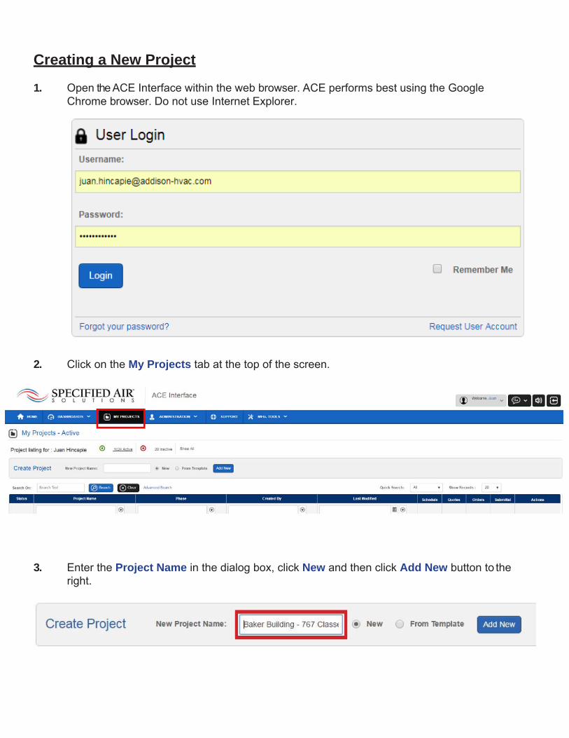
Creating a New Project
1. Open the ACE Interface within the web browser. ACE performs best using the Google Chrome browser. Do not use Internet Explorer.
2. Click on the My Projects tab at the top of the screen.
3. Enter the Project Name in the dialog box, click New and then click Add New button to the right.
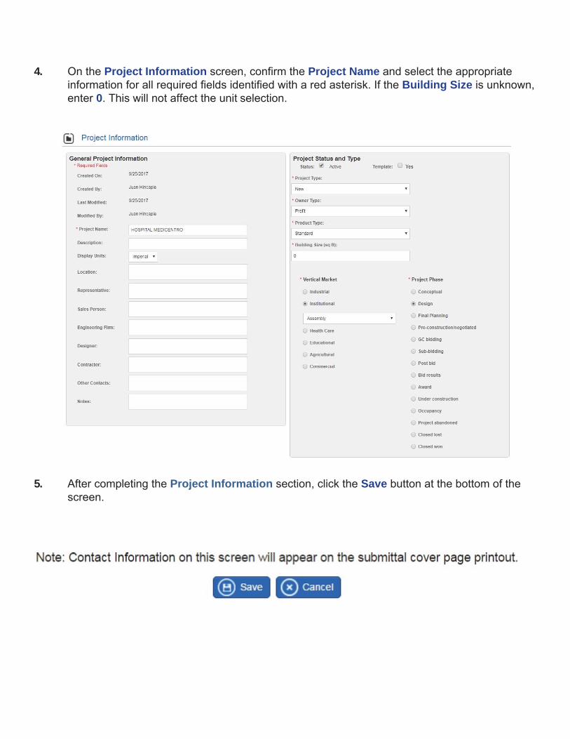
4. On the Project Information screen, confirm the Project Name and select the appropriate information for all required fields identified with a red asterisk. If the Building Size is unknown, enter 0. This will not affect the unit selection.
5. After completing the Project Information section, click the Save button at the bottom of the screen.
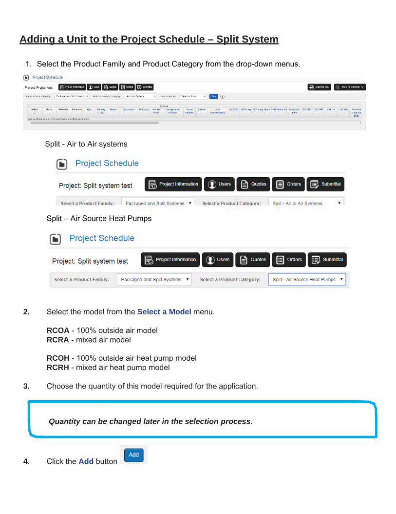
Adding a Unit to the Project Schedule – Split System 1. Select the Product Family and Product Category from the drop-down menus.
1. Select the Product Family and Product Category from the drop-down menus.
Split - Air to Air systems
Split – Air Source Heat Pumps
2. Select the model from the Select a Model menu.
RCOA - 100% outside air model RCRA - mixed air model RCOH - 100% outside air heat pump model RCRH - mixed air heat pump model
3. Choose the quantity of this model required for the application.
4. Click the Add button
Quantity can be changed later in the selection process.

Selecting the Unit Enter the unit tag referenced in the equipment schedule in the Tagging box within the Design Inputs section. 1. Leave the Unit Size set to Auto. This will allow the ACE tool to provide potential configurations
that will meet the application criteria.
2. Select the Unit Voltage for both CU and AHU
3. Select the Air Volume Application. 6 Select the Cabinet options.
7. Select the Heating Type from the drop-down menu. Additional information is provided in the Heat Selections section.
8. Enter the design CFM in the Total Airflow box. On mixed air units, enter the Outside Airflow
requirement in the associated box.
9. Enter the design external static pressure in the External SP box.
10. Enter the altitude of the equipment application in the Altitude box.
11. Enter the outdoor Ambient temperature and the EAT DB and EAT WB in the DX – Air Cooled
box
12. For heat pumps enter the Ambient (heating) design temperature and the EAT DB temperature during mechanical heat operation.

Heat Selections
The heat criteria box displayed is dependent on the Heating Type selection in the Design Inputs box.
- Hot water heat - skip to step 13 - Electric heat - skip to step 18
Supplemental and Auxiliary Heat
When selecting additional heat sources on air source heat pumps, an understanding of the difference between supplemental and auxiliary heat is necessary.
Supplemental heat is used when the mechanical heat available from the heat pump system is not sufficient to reach the desired leaving unit air temperature. In these situations, additional heat is added after the primary DX coil through the use of electric heat strips, gas heat, hot water or steam coils.
On supplemental heat applications, the capacity of the additional heat source adds to the heat capacity available from the heat pump system at design conditions.
On auxiliary heat applications, the capacity of the additional heat source is capable of supporting the entire heating load without heat from the heat pump system. This can serve as a redundant heat system in case of heat pump system failure or emergency heat in situations where the outdoor ambient temperature is too low for efficient heat pump heating operation.
Systems equipped for auxiliary heat operation are also capable of providing supplemental heat. This is accomplished by a control defined balance point or Compressor Disable temperature.
When selecting a DOAS unit with supplemental heat only, leave the Auxiliary button unchecked in the ACE selection tool Electric Heat or Hot Water heat box. The EAT DB for additional heat will auto calculate based on the heat pump output within the software.
When selecting a DOAS unit with auxiliary heat, select the Auxiliary button in the ACE selection tool Electric Heat, Gas Furnace, Steam or Hot Water heat box. The EAT DB box must be changed to the design condition for auxiliary heat operation.
On auxiliary heat applications, the heating design OA temperature will be below the specified unit balance point or Compressor Disable temperature. This information is often located in the equipment specifications report.
Hot Water
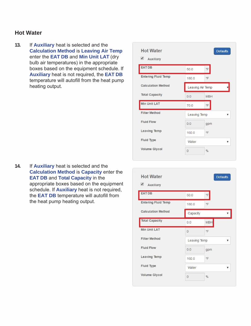
13. If Auxiliary heat is selected and the
Calculation Method is Leaving Air Temp enter the EAT DB and Min Unit LAT (dry bulb air temperatures) in the appropriate boxes based on the equipment schedule. If Auxiliary heat is not required, the EAT DB temperature will autofill from the heat pump heating output.
14. If Auxiliary heat is selected and the
Calculation Method is Capacity enter the EAT DB and Total Capacity in the appropriate boxes based on the equipment schedule. If Auxiliary heat is not required, the EAT DB temperature will autofill from the heat pump heating output.
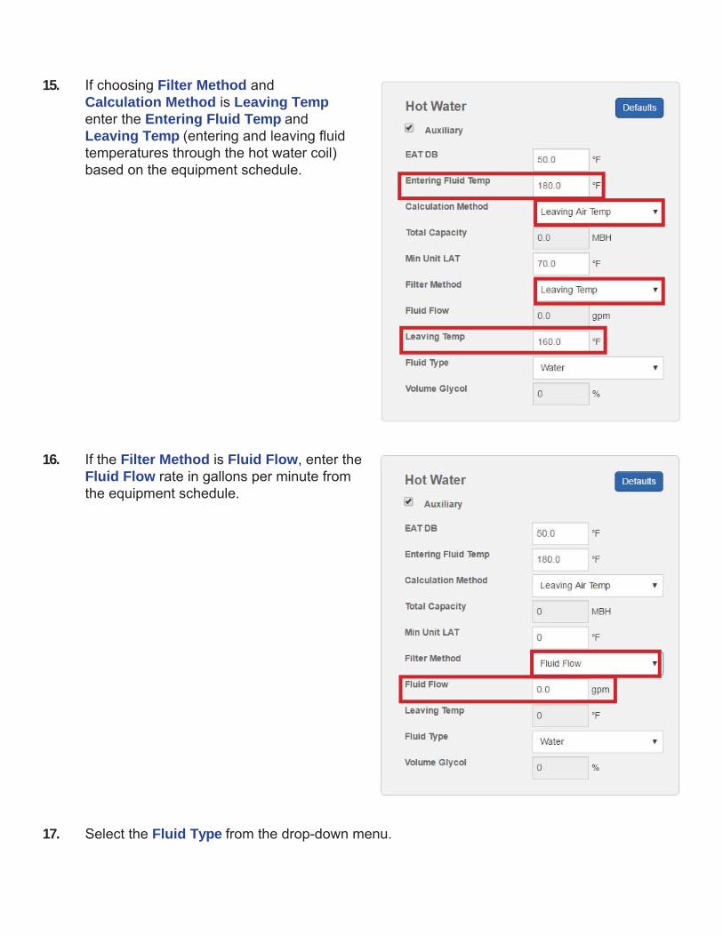
15. If choosing Filter Method and Calculation Method is Leaving Temp enter the Entering Fluid Temp and Leaving Temp (entering and leaving fluid temperatures through the hot water coil) based on the equipment schedule.
16. If the Filter Method is Fluid Flow, enter the
Fluid Flow rate in gallons per minute from the equipment schedule.
17. Select the Fluid Type from the drop-down menu.
Electric Heat
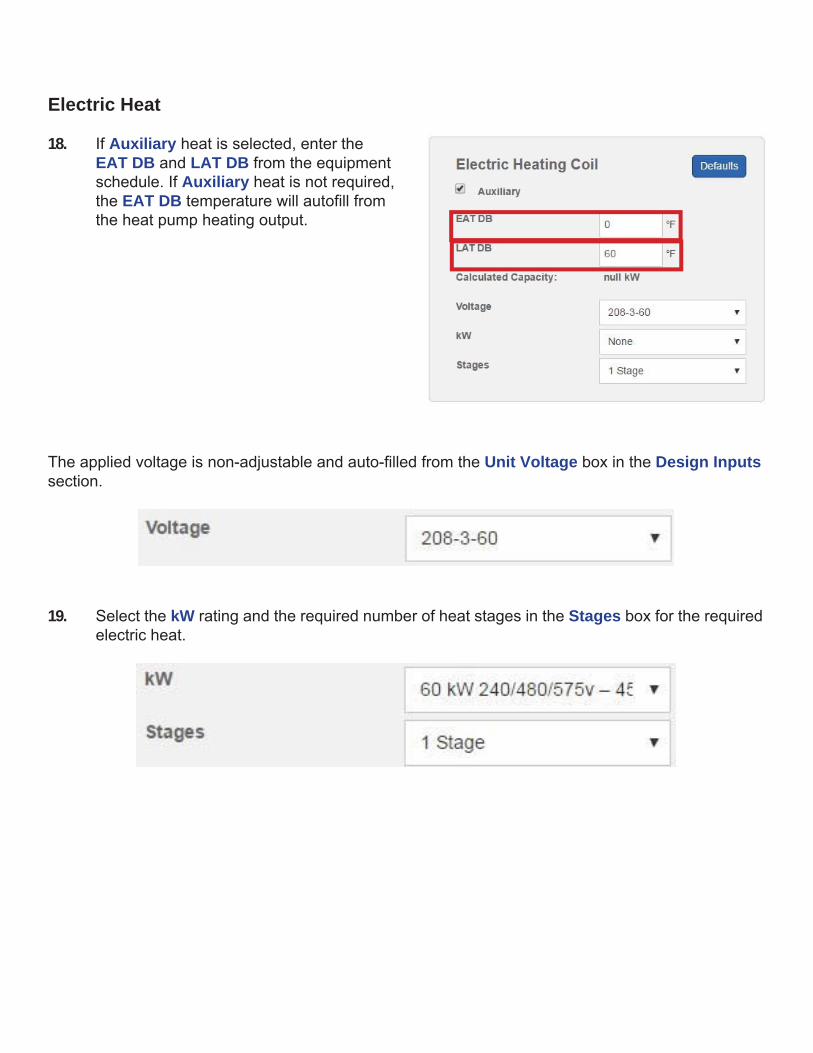
18. If Auxiliary heat is selected, enter the
EAT DB and LAT DB from the equipment schedule. If Auxiliary heat is not required, the EAT DB temperature will autofill from the heat pump heating output.
The applied voltage is non-adjustable and auto-filled from the Unit Voltage box in the Design Inputs section.
19. Select the kW rating and the required number of heat stages in the Stages box for the required electric heat.
Selecting the Unit (continued)
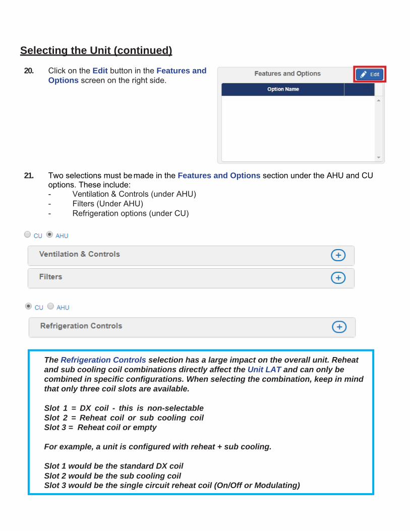
20. Click on the Edit button in the Features and Options screen on the right side.
21. Two selections must be made in the Features and Options section under the AHU and CU
options. These include: - Ventilation & Controls (under AHU) - Filters (Under AHU) - Refrigeration options (under CU)
The Refrigeration Controls selection has a large impact on the overall unit. Reheat and sub cooling coil combinations directly affect the Unit LAT and can only be combined in specific configurations. When selecting the combination, keep in mind that only three coil slots are available.
Slot 1 = DX coil - this is non-selectable Slot 2 = Reheat coil or sub cooling coil Slot 3 = Reheat coil or empty
For example, a unit is configured with reheat + sub cooling.
Slot 1 would be the standard DX coil Slot 2 would be the sub cooling coil Slot 3 would be the single circuit reheat coil (On/Off or Modulating)

22. After selecting the appropriate ventilation, filters and refrigeration options, click OK to exit the screen.
23. Select Calculate

Final Selection and Comparison
After making preliminary selections, the ACE Interface will provide potential units that fit the basic criteria in a Packaged and Split Systems Possible Selections screen. The initial selection criteria, airflow, cooling capacity, efficiency and heat section will determine what unit options are provided.
1. Compare the following information to the specified values on the equipment schedule and
select the best match.
- LAT DB/WB Coil - LAT DB/WB Unit - Total Cooling Capacity - Sensible Capacity - MCA/MFS - Cabinet size - consider options to move to a smaller cabinet that will still meet
performance requirements.

2. Select the unit by clicking on the model button at the top of the grid.
3. The ACE Interface will output a selection summary based on the model chosen.
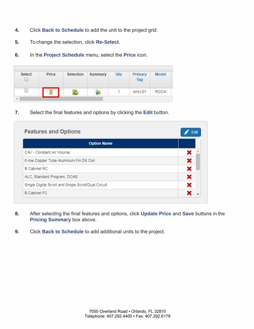
4. Click Back to Schedule to add the unit to the project grid. 5. To change the selection, click Re-Select.
6. In the Project Schedule menu, select the Price icon.
7. Select the final features and options by clicking the Edit button.
8. After selecting the final features and options, click Update Price and Save buttons in the
Pricing Summary box above. 9. Click Back to Schedule to add additional units to the project.
7050 Overland Road ▪ Orlando, FL 32810 Telephone: 407.292.4400 ▪ Fax: 407.292.6178