AccuShot Quick Start Guide - Great Plains · PDF fileThe AccuShot Quick Start Guide is for...
50
Transcript of AccuShot Quick Start Guide - Great Plains · PDF fileThe AccuShot Quick Start Guide is for...


-----------------------------------------------------------------------------------------------------Contents
CONTENTS
1.0 INTRODUCTION . . . . . . . . . . . . . . . . . . . . . . . . . . . 3
2.0 SAFETY . . . . . . . . . . . . . . . . . . . . . . . . . . . . . . . . . . 5
3.0 SETUP . . . . . . . . . . . . . . . . . . . . . . . . . . . . . . . . . . . 7AccuShot System – Screen ICON Description . . . . . 7HOME Screen . . . . . . . . . . . . . . . . . . . . . . . . . . . . . . 8PLACEMENT Settings . . . . . . . . . . . . . . . . . . . . . . . 9Procedure for Setting Liquid Bypass for AccuShot . 10Initial Setup . . . . . . . . . . . . . . . . . . . . . . . . . . . . . . . 11Close Main Bypass Valve . . . . . . . . . . . . . . . . . . . . 12Open Boom Shutoff Valve. . . . . . . . . . . . . . . . . . . . 12Activate Pump . . . . . . . . . . . . . . . . . . . . . . . . . . . . . 13Pressure Relief Valve Adjustment. . . . . . . . . . . . . . 14Pressure Gauge . . . . . . . . . . . . . . . . . . . . . . . . . . . 15DIAGNOSTICS SYSTEM Screen . . . . . . . . . . . . . . 17Activate the Key FOB Controls . . . . . . . . . . . . . . . . 19Operate the Key FOB Controls . . . . . . . . . . . . . . . . 20Purge Operation . . . . . . . . . . . . . . . . . . . . . . . . . . . 21Operate the System Info Screen. . . . . . . . . . . . . . . 22Valve Diagnostics . . . . . . . . . . . . . . . . . . . . . . . . . . 24TIP CALIBRATION Catch Test . . . . . . . . . . . . . . . . 25Tank Volume . . . . . . . . . . . . . . . . . . . . . . . . . . . . . . 29SENSOR SETTINGS - Factory Set. . . . . . . . . . . . . 30PUMP Settings - Factory Set . . . . . . . . . . . . . . . . . 32
4.0 FIELD OPERATION . . . . . . . . . . . . . . . . . . . . . . . . 35AUTO Mode . . . . . . . . . . . . . . . . . . . . . . . . . . . . . . 35Field Verify Seed and Shot Placement . . . . . . . . . . 36MANUAL Mode . . . . . . . . . . . . . . . . . . . . . . . . . . . . 39ON Mode. . . . . . . . . . . . . . . . . . . . . . . . . . . . . . . . . 42Active Seed / Valve Sensor Indicators . . . . . . . . . . 44OFF Mode . . . . . . . . . . . . . . . . . . . . . . . . . . . . . . . . 45
AccuShot™ | ©2015 Capstan Ag Systems, Inc. | Version: P-2.0 | 2/5/2016 | 1-----------------------------------------------------------------------------------------------------

-----------------------------------------------------------------------------------------------------Contents
System Control - Run / Hold. . . . . . . . . . . . . . . . . . 46
2 | AccuShot™ | ©2015 Capstan Ag Systems, Inc. | Version: P-2.0 | 2/5/2016
-----------------------------------------------------------------------------------------------------

-----------------------------------------------------------------------------------------------------1.0 - Introduction
1.0 INTRODUCTION
The AccuShot™ liquid delivery system is designed to apply a specific amount of liquid product at a specific location relative to each seed in the furrow. The correct amount of liquid product can now be delivered where the seed needs it...giving each seed a better shot at germination.
Application Based
To reduce seed burn and improve stand counts, the Operator supplies initial setup information via a VT Display so AccuShot can determine how close to the seed to apply the liquid product. By concentrating the liquid product where the seed needs it, AccuShot reduces wasted product between the seeds at wider seed spacings.
Results
Improved plant vigor and less wasted liquid product both drive more profit to the Producer’s bottom line with AccuShot.
Other Manuals
The AccuShot Quick Start Guide is for use with the companion AccuShot Operator and Maintenance Manual.
© 2015 CAPSTAN AG SYSTEMS, INC., All rights reserved. Capstan Ag Systems, Inc. shall retain sole ownership of Copyrights and Patents for the technology found in AccuShot; along with all documentation, which shall not be copied, in whole or in part, adapted, modified, or disseminated without written permission from Capstan Ag Systems, Inc. This equipment is an agricultural-based system operated by a trained operator and maintained by qualified personnel. Patented operational software, circuitry logic and processes supplied on each AccuShot product remain the exclusive property of Capstan Ag Systems, Inc.
is a trademark of Great Plains, Inc.
AccuShot™ | ©2015 Capstan Ag Systems, Inc. | Version: P-2.0 | 2/5/2016 | 3-----------------------------------------------------------------------------------------------------

-----------------------------------------------------------------------------------------------------1.0 - Introduction
THIS PAGE IS INTENTIONALLY LEFT BLANK
4 | AccuShot™ | ©2015 Capstan Ag Systems, Inc. | Version: P-2.0 | 2/5/2016
-----------------------------------------------------------------------------------------------------

-----------------------------------------------------------------------------------------------------2.0 Safety
2.0 SAFETY
This manual contains important information on how to safely, efficiently and correctly operate the AccuShot System. Following these instructions will help keep personnel safe, reduce downtime and increase the reliability and life of the equipment, its components and related systems.
• Review the Safety Information in the applicable tractor, planter and an-cilliary equipment manual(s).
• Follow the instructions (in this manual) for each step thoroughly to en-sure safe work conditions in and around the applicable tractor, planterand ancilliary equipment manual(s).
• It is important for all individuals working with chemicals to understand thepotential risks, necessary safety precautions and proper response in theevent of accidental contact.
• Review the applicable tractor, planter and ancilliary equipment manu-al(s) for chemical safety information.
• Review and understand procedures for obtaining and using Safety DataSheets (SDS)and the required Personal Protective Equipment(PPE) forwhen working around hazardous chemicals and sharp edges and ob-jects on applicable tractor, planter and ancillary equipment.
• Use the procedure in the appropriate Agricultural Equipment Manual forconnecting, disconnecting and jump starting the machine’s battery.
• Please keep this manual and all enclosed documentation in an accessi-ble location known to all operator personnel. Keep sparks and flamesaway from the battery. Battery gas can explode and cause serious injury.Do not smoke in battery charging area.
If you do not understand the AccuShot equipment after reading this manual, please obtain the proper training before working with the AccuShot system to ensure your own safety and well as your co-worker’s safety.
Make certain that all personnel have read this manual and thoroughly understand safe operating procedures.
AccuShot™ | ©2015 Capstan Ag Systems, Inc. | Version: P-2.0 | 2/5/2016 | 5-----------------------------------------------------------------------------------------------------

-----------------------------------------------------------------------------------------------------2.0 Safety
THIS PAGE IS INTENTIONALLY LEFT BLANK
6 | AccuShot™ | ©2015 Capstan Ag Systems, Inc. | Version: P-2.0 | 2/5/2016
-----------------------------------------------------------------------------------------------------

-----------------------------------------------------------------------------------------------------3.0 Setup
3.0 SETUP
AccuShot System – Screen ICON Description
Icon Icon Descriptions - LH Side of Monitor
Touch this icon to activate the AccuShot system.
Icon Icon Descriptions - RH Side of MonitorThe Alarm icon appears when there is an alarm in thesystem. Touch this icon to view and silence currentalarms.
Touch this icon to return to the Home Screen.
Touch this icon to open the Placement Settings Screen.
Touch this icon to open the Tip Calibration Screen.
Touch this icon to open the Diagnostics Screen.
Touch this icon to open the Tank Volume Screen.
Touch this icon to open the Active Seed/Valve SensorScreen.
Touch this icon to “go to” the Next Page of icons.
Touch this icon to open the Sensor Settings Screen.
Touch this icon to open the Pump Settings Screen.
AccuShot™ | ©2015 Capstan Ag Systems, Inc. | Version: P-2.0 | 2/5/2016 | 7-----------------------------------------------------------------------------------------------------
-----------------------------------------------------------------------------------------------------3.0 Setup
HOME Screen
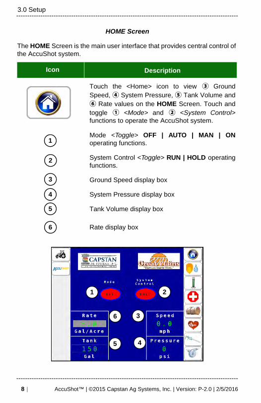
The HOME Screen is the main user interface that provides central control of the AccuShot system.
Icon Description
Touch the <Home> icon to view ③ GroundSpeed, ④ System Pressure, ⑤ Tank Volume and⑥ Rate values on the HOME Screen. Touch andtoggle ① <Mode> and ② <System Control>functions to operate the AccuShot system.
Mode <Toggle> OFF | AUTO | MAN | ONoperating functions.
System Control <Toggle> RUN | HOLD operatingfunctions.
Ground Speed display box
System Pressure display box
Tank Volume display box
Rate display box
2
1
3
4
5
6
1 2
3
45
6
8 | AccuShot™ | ©2015 Capstan Ag Systems, Inc. | Version: P-2.0 | 2/5/2016
-----------------------------------------------------------------------------------------------------

-----------------------------------------------------------------------------------------------------3.0 Setup
PLACEMENT Settings
Use the PLACEMENT SETTINGS Screen to enter / edit the placement and location of the shot in relation to the location of the seed.
Icon Description
Touch the <Seed Droplet> icon to set Population, num-ber of Planter Rows, Planter Width, Application Rate, System Pressure, Target Speed, and shot Distance from the seed.
Settings Defaults Units of Measure
Population 32.0 Thousand (k) Seed per Acre
Number of Rows 32
Planter Width 480 Inch
Application Rate 5.0 Gallon per Acre
Pressure Set Point 30.0 PSI
Target Speed 5.0 MPH
Dist. From Seed 1.0 Inch
Squirt Length 1.7 Inch
A warning will appear on the PLACEMENT SETTINGS Screen when Operator-entered values may not match or align with other settings. Read the warning and touch <Accept>, <Cancel> or <OK> to continue.
AccuShot™ | ©2015 Capstan Ag Systems, Inc. | Version: P-2.0 | 2/5/2016 | 9-----------------------------------------------------------------------------------------------------

-----------------------------------------------------------------------------------------------------3.0 Setup
Procedure for Setting Liquid Bypass for AccuShot
When the add-on hydraulically-driven centrifugal pump must run at different operating points on the AccuShot system, a ① liquid product bypass line(s) is (are) used to return some of the liquid back to the liquid product tank(s). This allows the pump to operate efficiently and reliably at its best efficiency point. If the pumped liquid product was returned through the suction line connections, turbulences at the pump suction would cause operational problems and even equipment damage.
AccuShot uses a Main Bypass Valve ②near the product pump and a Liquid Product Shutoff Valve ③ on the lower backside of each liquid product tank to manage different operating points. A total of up to 5.5 GPM of hydraulic flow is needed to operate the AccuShot system.
1
3
2
10 | AccuShot™ | ©2015 Capstan Ag Systems, Inc. | Version: P-2.0 | 2/5/2016
-----------------------------------------------------------------------------------------------------
-----------------------------------------------------------------------------------------------------3.0 Setup
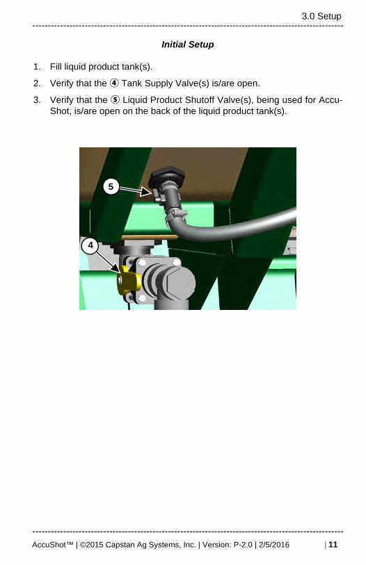
Initial Setup
1. Fill liquid product tank(s).
2. Verify that the ④ Tank Supply Valve(s) is/are open.
3. Verify that the ⑤ Liquid Product Shutoff Valve(s), being used for Accu-Shot, is/are open on the back of the liquid product tank(s).
4
5
AccuShot™ | ©2015 Capstan Ag Systems, Inc. | Version: P-2.0 | 2/5/2016 | 11
-----------------------------------------------------------------------------------------------------

-----------------------------------------------------------------------------------------------------3.0 Setup
Close Main Bypass Valve
4. Close the ① main bypass valve (near the product pump) on the Planter.
Closing Main Bypass Valve
Open Boom Shutoff Valve
5. Open ① shutoff valve to booms on the liquid product line.
6. Start the Tractor.
7. Engage the Planter Hydraulics
Opening Boom Shutoff Valve
1
1
12 | AccuShot™ | ©2015 Capstan Ag Systems, Inc. | Version: P-2.0 | 2/5/2016
-----------------------------------------------------------------------------------------------------

-----------------------------------------------------------------------------------------------------3.0 Setup
Activate Pump
8. Touch the red Key FOB Mode button on the DIAGNOSTIC Screen (thebutton will turn green and the function buttons will appear).
9. Start the liquid product pump by touching the ① pump <ON/OFF> button on the DIAGNOSTIC Screen or by pressing the button on the Key FOB.
Activate Pump
Icon Description
On the HOME Screen:
Touch the red <Diagnostic> icon on the right hand side of the HOME Screen.
1
1
AccuShot™ | ©2015 Capstan Ag Systems, Inc. | Version: P-2.0 | 2/5/2016 | 13
-----------------------------------------------------------------------------------------------------

-----------------------------------------------------------------------------------------------------3.0 Setup
Pressure Relief Valve Adjustment
10. While viewing the ① manual pressure gauge at the liquid product pump,adjust the ② pressure relief valve to set the pressure at 70 PSI maxi-mum.
Rotate CCW to decrease pressure.
Rotate CW to increase pressure.
11. Once pressure is set, use the locknut to lock the setting in place.
12. Open the main bypass valve (near the product pump) to the 10 o’clockposition.
1
2
14 | AccuShot™ | ©2015 Capstan Ag Systems, Inc. | Version: P-2.0 | 2/5/2016
-----------------------------------------------------------------------------------------------------

-----------------------------------------------------------------------------------------------------3.0 Setup
Pressure Gauge
13. While viewing the manual pressure gauge on planter, verify the pressureis 60 PSI. If not 60 PSI, do the following steps:
a. Under 60 PSI
i. Increase hydraulic flow to the planter hydraulics until 60 PSIis reached on the manual pressure gauge on the planter.
1. If hydraulics cannot get the pressure to 60 PSI, close① main bypass valve till pressure reaches 60 PSI.(Some bypass is needed for better AccuShot opera-tion.)
2. If pressure does not reach 60 PSI with main bypassfully closed, tractor hydraulic supply is not sufficient.Contact your Planter dealer for further assistance.
b. Above 60 PSI
i. Decrease hydraulic flow to the planter hydraulics until 60PSI is reached on the manual pressure gauge on theplanter.
1
AccuShot™ | ©2015 Capstan Ag Systems, Inc. | Version: P-2.0 | 2/5/2016 | 15
-----------------------------------------------------------------------------------------------------

-----------------------------------------------------------------------------------------------------3.0 Setup
14. Shut off the product pump by touching the pump on/off button on thescreen or Key FOB.
15. The bypass valve should be set at the correct pressure and flow afterperforming the above steps. Recheck pressure gauge on planter to ver-ify.
Minor hydraulic pump adjustment might be required when planting. See PUMP Settings - Factory Set on page 32.
16 | AccuShot™ | ©2015 Capstan Ag Systems, Inc. | Version: P-2.0 | 2/5/2016
-----------------------------------------------------------------------------------------------------

-----------------------------------------------------------------------------------------------------3.0 Setup
DIAGNOSTICS SYSTEM Screen
1. Enable Test Speed and/or Test Pressure for diagnostics and trouble-shooting.
2. Activate Key FOB operation.
3. View System Info.
4. Running valve diagnostics.
Icon Description
Touch the red Diagnostics icon to view the
DIAGNOSTIC Screen.
Select and toggle any of the red buttons on the Diagnostics Screen. This screen allows Key FOB use, viewing System Info and running Valve Diagnostics. The selected button will turn green when activated. Make sure the <Mode> button on the HOME Screen reads OFF to use the Key FOB and view diagnostics.
Procedure
The Operator can perform the following functions on the DIAGNOSTICScreen:
AccuShot™ | ©2015 Capstan Ag Systems, Inc. | Version: P-2.0 | 2/5/2016 | 17
-----------------------------------------------------------------------------------------------------

-----------------------------------------------------------------------------------------------------3.0 Setup
• HOME Screen in the center of the Speed and/or Pressure display boxes.• TIP CALIBRATION Screen in the System Pressure box at the bottom of
the screen.
Procedure
Touch to toggle any of the red buttons on the DIAGNOSTIC screen. The toggled button will turn green when activated.
When a Test Speed and/or Test Pressure procedure is enabled for trou-bleshooting and diagnostics, “TEST” will blink on the following two menu screens:
Both Test Speed and Test Pressure values can be edited (one at a time) from the DIAGNOSTIC Screen, by touching inside the value display box
to activate the keypad. Once a number is selected, touch the key to enter the chosen number.
18 | AccuShot™ | ©2015 Capstan Ag Systems, Inc. | Version: P-2.0 | 2/5/2016
-----------------------------------------------------------------------------------------------------

-----------------------------------------------------------------------------------------------------3.0 Setup
Activate the Key FOB Controls
Icon Description
Touch the red <Diagnostics> icon.
Procedure
Touch the red <Keyfob Mode> button on the DIAGNOS-TIC Screen to display the Key FOB function buttons.
Key FOB Mode Active will blink on the DIAGNOSTIC Screen and the red button will turn green.
AccuShot™ | ©2015 Capstan Ag Systems, Inc. | Version: P-2.0 | 2/5/2016 | 19
-----------------------------------------------------------------------------------------------------

-----------------------------------------------------------------------------------------------------3.0 Setup
Operate the Key FOB Controls
Icon Description
① Pulse Nozzles Right to Left.
② Turn Pump ON/OFF.
③ Pulse Nozzles Left to Right.
④ Repeat Current Nozzle Pulse.
NOTE: Button ④ has a dualfunction. During Tip Calibration, it isused to Start/Stop the TipCalibration Catch Test.
Procedure
Operator can also use the Key FOB or the AccuShot DIAGNOSTIC Screen in the Cab to clear any plugged rows, remove air from the system, and test row-by-row to ensure that all rows are still working properly.
The row number being tested can be edited from the DIAGNOSTIC Screen with Key FOB Controls activated.
Touch the inside of the “Now Testing Row” display box to enable the keypad. Touch / edit the row number being
tested. Touch the key to enter the value.
If the <Mode> is not set to OFF on the HOME Screen, a warning will appear when enabling Key FOB Mode.
1
2
3
4
20 | AccuShot™ | ©2015 Capstan Ag Systems, Inc. | Version: P-2.0 | 2/5/2016
-----------------------------------------------------------------------------------------------------

-----------------------------------------------------------------------------------------------------3.0 Setup
Purge Operation
The Operator can prime, purge the air or flush the AccuShot plumbing system from the DIAGNOSTIC Screen with the Key FOB Mode activated.
At the start of every planting day, an Operator should (at the very least) run the Purge All Valves operation to check the system for air or contamination.
Icon Description
To perform the Purge Operation, the VT Display must be on the DIAGNOSTIC Screen with no active warnings. (Read / Review Section 3.4 in the AccuShot Operator and Maintenance Manual.
Make sure the Key FOB Controls are activated and dis-plays a green <Keyfob Mode> button.
Procedure
Touch the red <Purge All Valves> button to start purge operation.
The red <Purge All Valves> button will turn green and all nozzle valves will open 100%, allowing a constant liquid flow from the product tank, through the plumbing system and discharging through the nozzle valves.
Purge will end when touching the green <Purging Valves> button, pressing any of the top 4 Key FOB buttons or touch-ing the Key FOB buttons on the DIAGNOSTIC Screen, or leaving the DIAGNOSTIC Screen.
AccuShot™ | ©2015 Capstan Ag Systems, Inc. | Version: P-2.0 | 2/5/2016 | 21
-----------------------------------------------------------------------------------------------------

-----------------------------------------------------------------------------------------------------3.0 Setup
Operate the System Info Screen
Icon Description
Touch the <System Info> button to display more information. The button will turn green when enabled. Operator can view System Voltage, Hour Meter, Pressure Sensor Voltage, Pump Duty Cycle, and GPS readouts.
22 | AccuShot™ | ©2015 Capstan Ag Systems, Inc. | Version: P-2.0 | 2/5/2016
-----------------------------------------------------------------------------------------------------

-----------------------------------------------------------------------------------------------------3.0 Setup
Touch the SW Versions button to view the AccuShot Controller’s circuit board information.
Circuit Board Information
AccuShot™ | ©2015 Capstan Ag Systems, Inc. | Version: P-2.0 | 2/5/2016 | 23
-----------------------------------------------------------------------------------------------------

-----------------------------------------------------------------------------------------------------3.0 Setup
Valve Diagnostics
Icon Description
Touch the red <Diagnostics> icon on the HOME Screen.
Touch the <Valve Diag> button. The button will turn green. The Operator can see if all nozzle valves and seed sensors are connected.
Icon Indicator Color Key
Indicates seed sensor and nozzlevalves are connected.
Indicates nozzle valve is connected while seed sensor is not being detected by controller.
Indicates seed sensor is connected while the nozzle valve is not being detected by controller.
See the AccuShot Operator and Maintenance Manual for more diagnostic help, if needed.
If the <Mode> is not set to OFF on the HOME Screen, a warning will appear when enabling Valve Diagnostics.
24 | AccuShot™ | ©2015 Capstan Ag Systems, Inc. | Version: P-2.0 | 2/5/2016
-----------------------------------------------------------------------------------------------------

-----------------------------------------------------------------------------------------------------3.0 Setup
TIP CALIBRATION Catch Test
Icon Description
The TIP CALIBRATION Screen is used to compensate for different viscosities and fluid dynamics.
1. Touch the <Tip Calibration> icon on the HOME Screen.
2. Verify and edit Tip Calibration information as needed. Changing val-ues on the TIP CALIBRATION Screen will also change the samevalues in the PLACEMENT SETTINGS Screen or vice versa.
Verify that the Tip Size is correct.
Spray Tip size is verified by looking at the outside surface of the tip near the spray end.
Procedure
3. Place the Calibration Pitcher directly underneath a spray nozzle onRow #1 of the Planter.
4. With the planter hydraulics engaged, touch the <START> button on the TIP CALIBRATION Screen or press button 4 on the Key FOB to begin the Tip Calibration Catch Test.
AccuShot™ | ©2015 Capstan Ag Systems, Inc. | Version: P-2.0 | 2/5/2016 | 25
-----------------------------------------------------------------------------------------------------
-----------------------------------------------------------------------------------------------------3.0 Setup
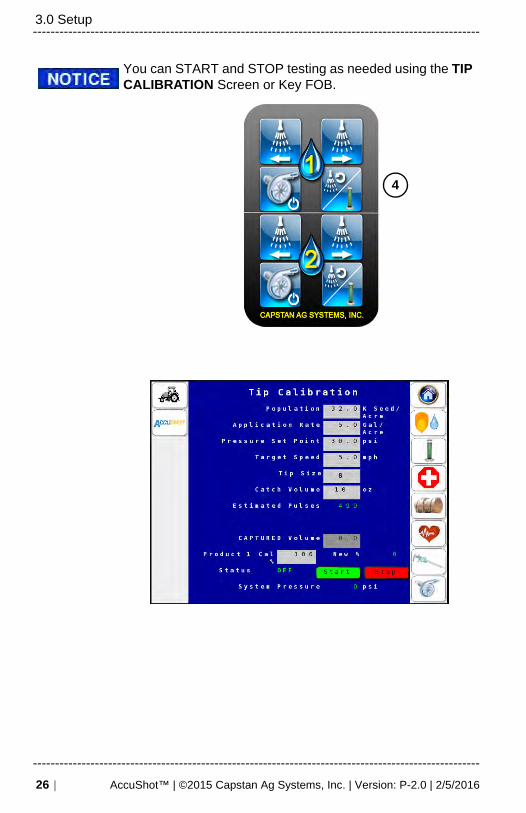
You can START and STOP testing as needed using the TIP CALIBRATION Screen or Key FOB.
4
26 | AccuShot™ | ©2015 Capstan Ag Systems, Inc. | Version: P-2.0 | 2/5/2016
-----------------------------------------------------------------------------------------------------
-----------------------------------------------------------------------------------------------------3.0 Setup
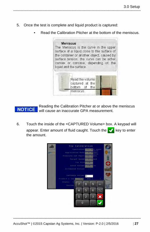
5. Once the test is complete and liquid product is captured:
• Read the Calibration Pitcher at the bottom of the meniscus.
Reading the Calibration Pitcher at or above the meniscus will cause an inaccurate GPA measurement.
6. Touch the inside of the <CAPTURED Volume> box. A keypad will
appear. Enter amount of fluid caught. Touch the key to enter the amount.
AccuShot™ | ©2015 Capstan Ag Systems, Inc. | Version: P-2.0 | 2/5/2016 | 27
-----------------------------------------------------------------------------------------------------

-----------------------------------------------------------------------------------------------------3.0 Setup
7. Once a CAPTURED Volume is entered, Touch
or
• A new Product 1 Cal% will be calculated. Touch <Accept> to se-lect new value or <Decline> to return to previous Product 1Cac%.
8. Repeat Catch Test until the correct catch volume is caught.
If the <Mode> is not set to OFF on the HOME Screen, a warning will appear when accessing the TIP CALIBRATION Screen.
28 | AccuShot™ | ©2015 Capstan Ag Systems, Inc. | Version: P-2.0 | 2/5/2016
-----------------------------------------------------------------------------------------------------

-----------------------------------------------------------------------------------------------------3.0 Setup
Tank Volume
The TANK VOLUME Screen can also be accessed by touching the <Tank> volume box on the HOME Screen.
Icon DescriptionTouch the <Tank> icon to view and set the Tank Volume and set the Warning Level.
Touching the <Tank> volume box on the HOME Screen opens the TANK INVENTORY Screen.
AccuShot™ | ©2015 Capstan Ag Systems, Inc. | Version: P-2.0 | 2/5/2016 | 29
-----------------------------------------------------------------------------------------------------

-----------------------------------------------------------------------------------------------------3.0 Setup
SENSOR SETTINGS - Factory Set
All settings are locked on this screen except the Flowmeter Cal. Locked screens are intended only for qualified Service Technician access and use.
The Flowmeter Cal value entered must match the Flowmeter (label) on the Planter. The Flowmeter Cal Value IS NOT locked and must be set by operator.
Icon Description
The default Sensor Settings are set at the factory.
Touch the LOCK icon to open the on-screen key-board.
30 | AccuShot™ | ©2015 Capstan Ag Systems, Inc. | Version: P-2.0 | 2/5/2016
-----------------------------------------------------------------------------------------------------

-----------------------------------------------------------------------------------------------------3.0 Setup
Type in the password and touch the key to enter the password and UNLOCK the screen.
Defaults
1. Pressure Sensor Voltage Low = 0.5VDC
2. Pressure Sensor Voltage High = 5.0VDC
3. Pressure Sensor Low = 0.0 PSI
4. Pressure Sensor High = 100.0 PSI
5. Radar Cal = 60.0 Pulse per 400 ft.
6. Row Fail Rate = 1 Seeds per sec.
7. Flowmeter Cal = 1740 Pulse per 10Gals.
AccuShot™ | ©2015 Capstan Ag Systems, Inc. | Version: P-2.0 | 2/5/2016 | 31
-----------------------------------------------------------------------------------------------------

-----------------------------------------------------------------------------------------------------3.0 Setup
PUMP Settings - Factory Set
All settings are locked on this screen. Locked screens are intended only for qualified Service Technician access and use.
Procedure After UNLOCK
Adjust Hydraulic pump settings by using the System Gain setting to tune a system where the pressure is oscillating or sluggish to respond.
• Select a lower number to stabilize an oscillating system.
• Select a higher number to speed up a sluggish system.Icon Description
The default Pump Settings are set at the factory.
Touch the LOCK icon to open the on-screen keyboard.
Type in the password and touch the key to enter the password and UNLOCK the screen.
32 | AccuShot™ | ©2015 Capstan Ag Systems, Inc. | Version: P-2.0 | 2/5/2016
-----------------------------------------------------------------------------------------------------

-----------------------------------------------------------------------------------------------------3.0 Setup
Settings Default Units of Measure
P 5 N/A
I 2 N/A
D 0 N/A
System Gain 4 N/A
Flow Meter Filter 5.0 Sec.
Pressure Sensor Filter 2.0 Sec.
Min Duty Cycle 20 N/A
Max Duty Cycle 55 N/A
AccuShot™ | ©2015 Capstan Ag Systems, Inc. | Version: P-2.0 | 2/5/2016 | 33
-----------------------------------------------------------------------------------------------------

-----------------------------------------------------------------------------------------------------3.0 Setup
THIS PAGE IS INTENTIONALLY LEFT BLANK
34 | AccuShot™ | ©2015 Capstan Ag Systems, Inc. | Version: P-2.0 | 2/5/2016
-----------------------------------------------------------------------------------------------------

-----------------------------------------------------------------------------------------------------4.0 Field Operation
4.0 FIELD OPERATION
AUTO Mode
Icon Description
On the HOME Screen:
Press <Mode> button and toggle to AUTO. In <Auto> mode, the system automatically adjusts the pressure, and activates the nozzle valves when seeds are sensed. This mode should be used for normal field operation.
Press <System Control> button and toggle to RUN. With the planter hydraulics engaged, the liq-uid product pump will turn on and raise the pres-sure to the pressure set point.
Touch and toggle <System Control> button to HOLD. Pump will shut OFF and nozzle valves will not pulse.
AccuShot™ | ©2015 Capstan Ag Systems, Inc. | Version: P-2.0 | 2/5/2016 | 35
-----------------------------------------------------------------------------------------------------

-----------------------------------------------------------------------------------------------------4.0 Field Operation
Field Verify Seed and Shot Placement
A field check should be completed at the initial trip to the field and again whenever the distance to the seed is changed. See Chapter 4.0 in the AccuShot Operator and Maintenance Guide for detail images of this procedure.
To perform the seed and shot placement check, complete the following steps:
1. On the AccuShot HOME Screen, touch and toggle <System Con-trol> button to select HOLD.
2. At the back of the planter, using tie-down straps, secure up theclosing wheels and shallow up the Side Gauge Wheel depth on therows to be checked. (Recommend on a twin row to perform checkprocedures on rows next to each other. i.e. row 1 and 2).
3. Using the excess from the tie-down strap, or using a bungee strap,hold the seed firmer out of the furrow.
36 | AccuShot™ | ©2015 Capstan Ag Systems, Inc. | Version: P-2.0 | 2/5/2016
-----------------------------------------------------------------------------------------------------

-----------------------------------------------------------------------------------------------------4.0 Field Operation
4. Once everything is out of the furrow and off the dirt and secured,return to the tractor cab. On the AccuShot HOME Screen, touchand toggle <System Control> button to select RUN. Resume plant-ing for the desired test distance, using the same settings andspeeds as normal planting.
5. Stop the tractor once test distance is reached. On the AccuShotHOME Screen, touch and toggle <System Control> button toselect HOLD. Visually verify placement of shot relative to seed inthe furrow.
AccuShot™ | ©2015 Capstan Ag Systems, Inc. | Version: P-2.0 | 2/5/2016 | 37
-----------------------------------------------------------------------------------------------------

-----------------------------------------------------------------------------------------------------4.0 Field Operation
6. When placement of the shot relative to the seed is correct, removeall straps and readjust the Side Gauge Wheel depth back to normaloperating depth. (See the manufacturer’s specific planter manualfor assistance.
Repeat field check periodically or when Rate and/or Dis-tance to Seed is modified.
a. If placement needs adjustment, change Distance to the Seedvalue on the PLACEMENT SETTINGS Screen.
b. Repeat field test to verify correct placement of shot relative toseed.
38 | AccuShot™ | ©2015 Capstan Ag Systems, Inc. | Version: P-2.0 | 2/5/2016
-----------------------------------------------------------------------------------------------------

-----------------------------------------------------------------------------------------------------4.0 Field Operation
MANUAL Mode
Manual Mode is used for troubleshooting or continuing to run when a pressure sensor has failed.
Icon Description
Touch the red Diagnostic icon to view the DIAG-NOSTIC Screen.
Touch to toggle the <Test Pressure> button to ENABLE the Test Pressure. Verify Test Pressure value is correct.
AccuShot™ | ©2015 Capstan Ag Systems, Inc. | Version: P-2.0 | 2/5/2016 | 39
-----------------------------------------------------------------------------------------------------

-----------------------------------------------------------------------------------------------------4.0 Field Operation
To edit the <Test Pressure> value if not correct, touch the pressure value box to enable the key-pad.
Upon enabling a <Test Pressure>, “TEST” will blink in the System Pressure box on the HOME and TIP CALIBRATION Screens.
40 | AccuShot™ | ©2015 Capstan Ag Systems, Inc. | Version: P-2.0 | 2/5/2016
-----------------------------------------------------------------------------------------------------

-----------------------------------------------------------------------------------------------------4.0 Field Operation
On the HOME Screen:
Touch and toggle <Mode> button to select MAN.
Touch and toggle <System Control> button to RUN.
Visually monitor the manual pressure gauge on the Planter.
Touch the “% DC” <Arrows> to INCREASE or DECREASE until the desired pressure is reached on the manual pressure gauge.
Touch and toggle <System Control> button to HOLD. Pump will shut OFF and nozzle valves will not pulse.
Pressure should be checked and readjusted once the planter is operating.
3 4% DC
AccuShot™ | ©2015 Capstan Ag Systems, Inc. | Version: P-2.0 | 2/5/2016 | 41
-----------------------------------------------------------------------------------------------------

-----------------------------------------------------------------------------------------------------4.0 Field Operation
ON Mode
Use ON mode to apply a constant stream of product. Orifice inserts will be required to achieve the desired GPA. (Use orifice rate charts to size the orifices correctly, or contact your local dealer.) The system automatically adjusts to maintain the pressure set-point. This pressure Set Point can be changed on the Placement Settings Screen.
Icon Description
Install Orifice Plates when running in ON Mode only. Remove orifice plates if wanting to run in Auto or Manual Mode.
On the HOME Screen:
Touch and toggle <Mode> button to select ON.
Touch and toggle <System Control> button to select RUN.
42 | AccuShot™ | ©2015 Capstan Ag Systems, Inc. | Version: P-2.0 | 2/5/2016
-----------------------------------------------------------------------------------------------------
-----------------------------------------------------------------------------------------------------4.0 Field Operation
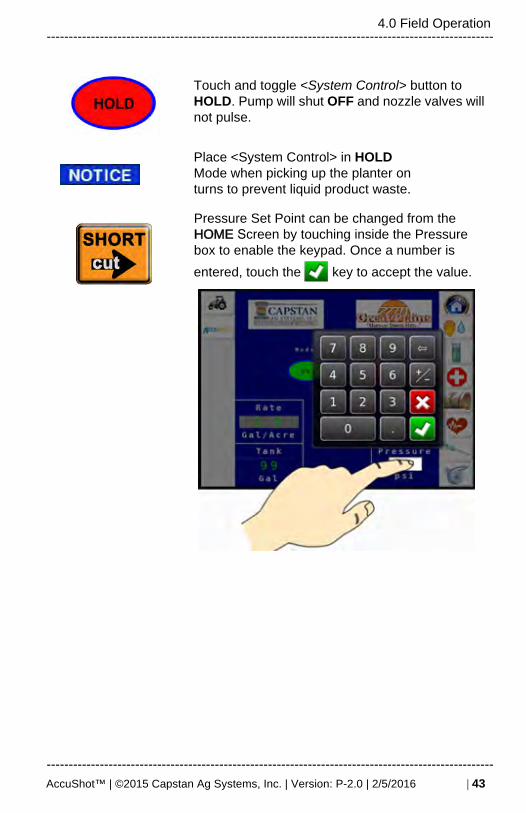
Touch and toggle <System Control> button to HOLD. Pump will shut OFF and nozzle valves will not pulse.
Place <System Control> in HOLDMode when picking up the planter onturns to prevent liquid product waste.
Pressure Set Point can be changed from the HOME Screen by touching inside the Pressure box to enable the keypad. Once a number is
entered, touch the key to accept the value.
AccuShot™ | ©2015 Capstan Ag Systems, Inc. | Version: P-2.0 | 2/5/2016 | 43
-----------------------------------------------------------------------------------------------------

-----------------------------------------------------------------------------------------------------4.0 Field Operation
Active Seed / Valve Sensor Indicators
Use this screen to verify the nozzle valves and seed sensors are working correctly while the planter is operating.
Icon Description
Touch the <Heart> icon to verify allrows are working in the Active Seed/Valve Sensor Screen. See troubleshooting for help with failed rows.
Icon Key to Indicator Colors
Indicates seed sensor and nozzle valves are con-nected.
Indicates seed sensor is not beingdetected by the AccuShot controller, while the nozzle valve is operational.
Indicates nozzle valve is not beingdetected by the AccuShotcontroller while the seed sensor isoperational.
44 | AccuShot™ | ©2015 Capstan Ag Systems, Inc. | Version: P-2.0 | 2/5/2016
-----------------------------------------------------------------------------------------------------

-----------------------------------------------------------------------------------------------------4.0 Field Operation
OFF Mode
Icon Description
When the Mode is switched to OFF, the system shuts down (pump and nozzle valves), and all alarms are deactivated. Choose the OFF Mode when the liquid product system is not being used.
Touch and toggle <Mode> button to select OFF.
System Control defaults to HOLD when the <Mode> button is toggled.
AccuShot™ | ©2015 Capstan Ag Systems, Inc. | Version: P-2.0 | 2/5/2016 | 45
-----------------------------------------------------------------------------------------------------
-----------------------------------------------------------------------------------------------------4.0 Field Operation
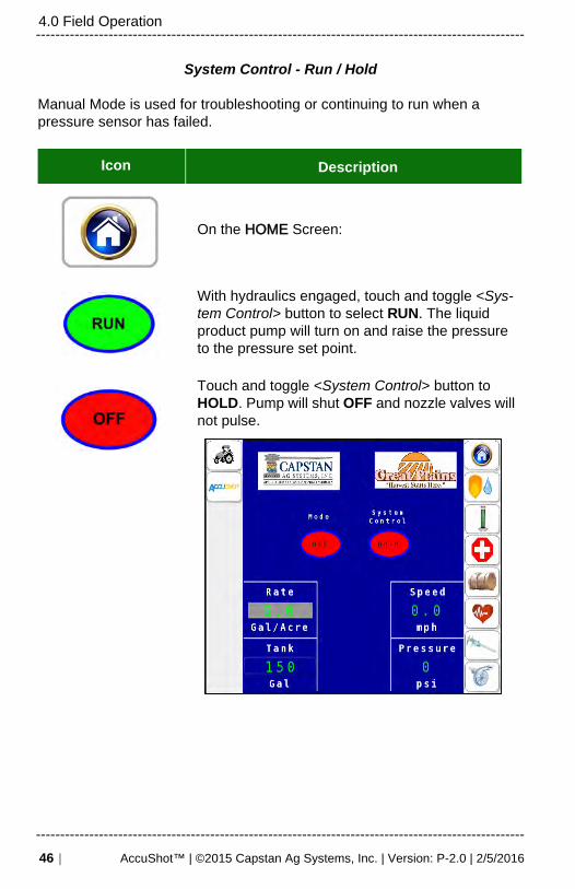
System Control - Run / Hold
Manual Mode is used for troubleshooting or continuing to run when a pressure sensor has failed.
Icon Description
On the HOME Screen:
With hydraulics engaged, touch and toggle <Sys-tem Control> button to select RUN. The liquid product pump will turn on and raise the pressure to the pressure set point.
Touch and toggle <System Control> button to HOLD. Pump will shut OFF and nozzle valves will not pulse.
46 | AccuShot™ | ©2015 Capstan Ag Systems, Inc. | Version: P-2.0 | 2/5/2016
-----------------------------------------------------------------------------------------------------