Accuseal Hydrocarbon Processing Valves // 2017...hydrocarbon residue taken out from partial reboiler...
16
Smart Solutions. Powerful Products. Accuseal ® Hydrocarbon Processing Valves // 2017
Transcript of Accuseal Hydrocarbon Processing Valves // 2017...hydrocarbon residue taken out from partial reboiler...
Smart Solutions. Powerful Products.
Accuseal® Hydrocarbon Processing Valves //2017

2//
EXPERIENCE, DEDICATION AND VISION
Introducing Forum Energy Technologies – a global provider of manufactured technologies and applied products and services. We may be a new name to you but our equipment and employees have a long history of solving our customers’ challenges. FET brings together some of the most well-known brands in our industry with an extensive range of mission critical products and services. We are building a world class company to bring innovative solutions to our worldwide customers. With offices in the key oilfield distribution centers of the globe, Forum is well-positioned to supply our clients with the equipment and related services that improve safety and performance and lower operating costs.
Forum’s products and services range from the underwater reservoir to the refinery, from the sea floor to the above ground transportation line. We pride ourselves on giving you a comprehensive offering of solutions to maximize your operations and improve your bottom line. Our customers are our partners and we work with them to solve their ever-changing challenges.

//1
FORUM provides a broad range of chokes/control valves, to meet most applications from basic manual operated to fully automated systems. As the industry continues to increase technology demands, operators select FORUM to obtain best-in-class service, performance and value. We are ISO-9001 certified, thus assuring design and manufacturing of the highest quality products available in the market.
Hydrocarbon Processing
Why Accuseal® MSBV’s?
There is a difference! 2
Optimized Ball Valve Design 2
Engineering Software 2
Superior Valve Coatings 3
Omni-Lap 360°™ 3
Vacuum Seal Testing 3
Our Services
Manual Operations 4
Valve Automation 4
Testing 4
Valve Modification 4
Accuseal® Features 4
Refinery Overview
Refinery Flow Chart 5
Continuous Catalytic Reformer 6
Fluidized Catalytic Cracking 7
Delayed Coking 8
Gasification 9
Critical Service Valve (CSV)
Ball & Seats 10
Unidirectional & Bidirectional Flow 11
Dual Spring 11
CSV - Metal Seated Ball Valve
Applications 12
Materials of Construction 12
End Connections 12
Actuator Options 12
Features & Benefits 12
ASME Certification 13
Dimensions 13
Testing Procedures 13
Purge Port Options 13
2//
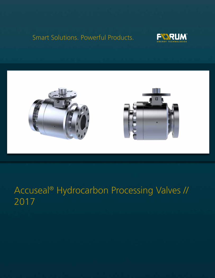
Why make Accuseal® your severe service metal-seated ball valve of choice?Demands on power generation plants are unprecedented. In combined cycle plants virtually every
unit is required to perform as a flexible generating plant, swinging in response to fluctuations in
energy demand. Mechanical equipment, including valves, must meet the frequent challenges
relating to cycling and thermal transience. Reliable, repeatable isolation has never been
more critical.
There is a difference!Many claim to be the best. All have a ball, seat and stem. But which valve most consistently
provides isolation under the most challenging of conditions? You choose severe service valves with
care because the consequences of failure are severe. COOPER® Valves provides many advantages in
power generation applications.
Accuseal® Valves delivers predictable reliability and performance• Optimized Ball Valve Design and Engineering Software
Proprietary software fast tracks optimal valve engineering.
• Superior Valve Coatings
Accuseal®'s state-of-the-art HP-HVOF (high pressure – high velocity oxygen fuel) coatings provide maximum
protection for longer valve life.
• Omni-Lap 360o TM
The propriretary Accuseal® mate-lapping process laps the entire spherical surface of the ball and seat surface,
not just the sealing band areas.
• Vacuum Seal Test
Accuseal® ball and seat sealing is tested prior to valve assembly, ensuring seal integrity.
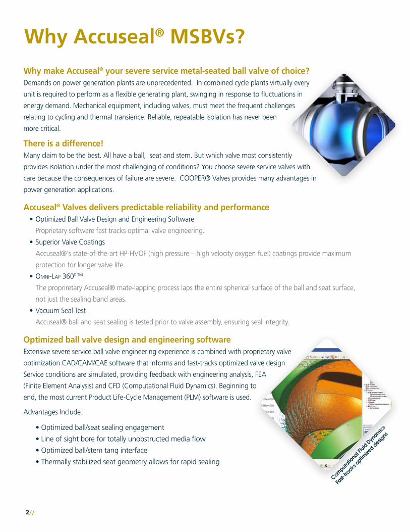
Optimized ball valve design and engineering softwareExtensive severe service ball valve engineering experience is combined with proprietary valve
optimization CAD/CAM/CAE software that informs and fast-tracks optimized valve design.
Service conditions are simulated, providing feedback with engineering analysis, FEA
(Finite Element Analysis) and CFD (Computational Fluid Dynamics). Beginning to
end, the most current Product Life-Cycle Management (PLM) software is used.
Advantages Include:
• Optimized ball/seat sealing engagement
• Line of sight bore for totally unobstructed media flow
• Optimized ball/stem tang interface
• Thermally stabilized seat geometry allows for rapid sealing
Why Accuseal® MSBVs?
//3
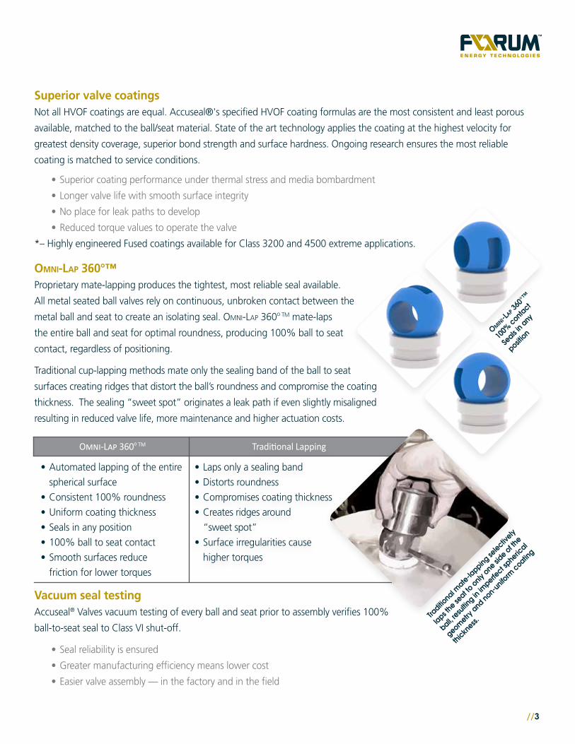
Superior valve coatingsNot all HVOF coatings are equal. Accuseal®'s specified HVOF coating formulas are the most consistent and least porous
available, matched to the ball/seat material. State of the art technology applies the coating at the highest velocity for
greatest density coverage, superior bond strength and surface hardness. Ongoing research ensures the most reliable
coating is matched to service conditions.
• Superior coating performance under thermal stress and media bombardment
• Longer valve life with smooth surface integrity
• No place for leak paths to develop
• Reduced torque values to operate the valve
*– Highly engineered Fused coatings available for Class 3200 and 4500 extreme applications.
Omni-Lap 360°™
Proprietary mate-lapping produces the tightest, most reliable seal available.
All metal seated ball valves rely on continuous, unbroken contact between the
metal ball and seat to create an isolating seal. Omni-Lap 360o TM mate-laps
the entire ball and seat for optimal roundness, producing 100% ball to seat
contact, regardless of positioning.
Traditional cup-lapping methods mate only the sealing band of the ball to seat
surfaces creating ridges that distort the ball’s roundness and compromise the coating
thickness. The sealing “sweet spot” originates a leak path if even slightly misaligned
resulting in reduced valve life, more maintenance and higher actuation costs.
Vacuum seal testing Accuseal® Valves vacuum testing of every ball and seat prior to assembly verifies 100%
ball-to-seat seal to Class VI shut-off.
• Seal reliability is ensured
• Greater manufacturing efficiency means lower cost
• Easier valve assembly — in the factory and in the field
Omni-Lap 360o TM
• Automated lapping of the entire
spherical surface
• Consistent 100% roundness
• Uniform coating thickness
• Seals in any position
• 100% ball to seat contact
• Smooth surfaces reduce
friction for lower torques
Traditional Lapping
• Laps only a sealing band
• Distorts roundness
• Compromises coating thickness
• Creates ridges around
“sweet spot”
• Surface irregularities cause
higher torques
4//
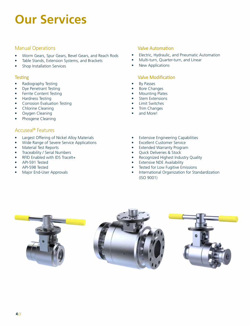
Accuseal® Features• Largest Offering of Nickel Alloy Materials• Wide Range of Severe Service Applications• Material Test Reports• Traceability / Serial Numbers• RFID Enabled with IDS TraceIt+• API-591 Tested• API-598 Tested• Major End-User Approvals
• Extensive Engineering Capabilities• Excellent Customer Service• Extended Warranty Program• Quick Deliveries & Stock• Recognized Highest Industry Quality• Extensive NDE Availability• Tested for Low Fugitive Emissions• International Organization for Standardization
(ISO 9001)
Our Services
Manual Operations
Valve ModificationTesting
Valve Automation• Worm Gears, Spur Gears, Bevel Gears, and Reach Rods• Table Stands, Extension Systems, and Brackets• Shop Installation Services
• Radiography Testing• Dye Penetrant Testing• Ferrite Content Testing• Hardness Testing• Corrosion Evaluation Testing• Chlorine Cleaning• Oxygen Cleaning• Phosgene Cleaning
• By Passes• Bore Changes• Mounting Plates• Stem Extensions• Limit Switches• Trim Changes• and More!
• Electric, Hydraulic, and Pneumatic Automation• Multi-turn, Quarter-turn, and Linear• New Applications
//5
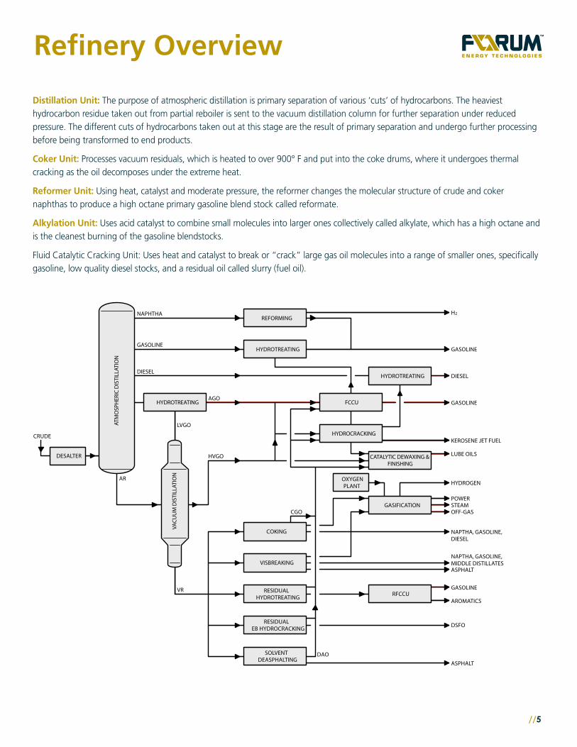
Refinery Overview
Distillation Unit: The purpose of atmospheric distillation is primary separation of various ‘cuts’ of hydrocarbons. The heaviest hydrocarbon residue taken out from partial reboiler is sent to the vacuum distillation column for further separation under reduced pressure. The different cuts of hydrocarbons taken out at this stage are the result of primary separation and undergo further processing before being transformed to end products.
Coker Unit: Processes vacuum residuals, which is heated to over 900° F and put into the coke drums, where it undergoes thermal cracking as the oil decomposes under the extreme heat.
Reformer Unit: Using heat, catalyst and moderate pressure, the reformer changes the molecular structure of crude and coker naphthas to produce a high octane primary gasoline blend stock called reformate.
Alkylation Unit: Uses acid catalyst to combine small molecules into larger ones collectively called alkylate, which has a high octane and is the cleanest burning of the gasoline blendstocks.
Fluid Catalytic Cracking Unit: Uses heat and catalyst to break or “crack” large gas oil molecules into a range of smaller ones, specifically gasoline, low quality diesel stocks, and a residual oil called slurry (fuel oil).
SOLVENTDEASPHALTING
RESIDUALEB HYDROCRACKING
RFCCU
DAOASPHALT
DSFO
AROMATICS
GASOLINE
OFF-GASSTEAMPOWER
HYDROGEN
LUBE OILS
KEROSENE JET FUEL
DIESELDIESEL
GASOLINE
NAPHTHA
GASOLINE
GASOLINE
ASPHALT
NAPTHA, GASOLINE, MIDDLE DISTILLATES
NAPTHA, GASOLINE, DIESEL
VISBREAKING
COKING
HYDROTREATING
REFORMING
HVGO
LVGO
AGO
CGO
VR
AR
CRUDE
DESALTER
OXYGENPLANT
GASIFICATION
VACU
UM
DIS
TILL
ATIO
N
ATM
OSP
HER
IC D
ISTI
LLAT
ION
HYDROTREATING
CATALYTIC DEWAXING &FINISHING
HYDROCRACKING
FCCUHYDROTREATING
RESIDUALHYDROTREATING
H 2
Refinery Overview

6//
9
6
3
13
12
2
4
11
6
10
9
77
8
5R
egen
To
wer
Rea
cto
rs
LiftEngager
LiftGas
N2N2
H2
LockhopperLockhopper
Surge
HopperAir
Air CatalystFunnel
Lift Engager
Valve SpecificationNumber Valve Description Temperature Pressure Pipe Size
1 Reactor Overhead Purge 400 – 1000 ºF 300 – 800 psi 1 – 8 inches
2 Reactor Overhead Regeneration 400 – 1000 ºF 300 – 800 psi 1 – 8 inches
3 Standby Reduction Zone Purge 400 – 1000 ºF 300 – 800 psi 1 – 8 inches
4 Reactor Bottoms Unloading Valve 400 – 1000 ºF 300 – 800 psi 1 – 8 inches
5
6
Hydrogen Loading to Lockhopper 400 – 700 ºF 300 – 700 psi 1 – 8 inches
7Hydrogen Vent for Lockhopper 400 – 700 ºF 300 – 700 psi 1 – 8 inches
8Nitrogen Purge for Lockhopper 400 – 700 ºF 300 – 700 psi 1 – 8 inches
9Catalyst to Lift Engager 400 – 700 ºF 300 – 700 psi 1 – 8 inches
10
11
Air Valve to Regeneration Cooler 400 – 700 ºF 300 – 700 psi 6 inches
12
Air Valve to Surge Hopper 400 – 700 ºF 300 – 700 psi 6 inches
13
Fresh Catalyst Addition 200 – 300 ºF 300 – 500 psi 2 – 8 inches
Regen Catalyst Unloading from Surge Hopper 400 – 700 ºF 300 – 700 psi 6 inchesPressure Balancing for Lockhopper / Lift Engager 400 – 700 ºF 300 – 700 psi 6 inches
1
Continuous Catalytic Reformer
89
6
3
13
12
2
4
11
6
10
9
77
8
5
Reg
en T
ow
er
Rea
cto
rs
LiftEngager
LiftGas
N2N2
H2
LockhopperLockhopper
Surge
HopperAir
Air CatalystFunnel
Lift Engager
Valve SpecificationNumber Valve Description Temperature Pressure Pipe Size
1 Reactor Overhead Purge 400 – 1000 ºF 300 – 800 psi 1 – 8 inches
2 Reactor Overhead Regeneration 400 – 1000 ºF 300 – 800 psi 1 – 8 inches
3 Standby Reduction Zone Purge 400 – 1000 ºF 300 – 800 psi 1 – 8 inches
4 Reactor Bottoms Unloading Valve 400 – 1000 ºF 300 – 800 psi 1 – 8 inches
5
6
Hydrogen Loading to Lockhopper 400 – 700 ºF 300 – 700 psi 1 – 8 inches
7Hydrogen Vent for Lockhopper 400 – 700 ºF 300 – 700 psi 1 – 8 inches
8Nitrogen Purge for Lockhopper 400 – 700 ºF 300 – 700 psi 1 – 8 inches
9Catalyst to Lift Engager 400 – 700 ºF 300 – 700 psi 1 – 8 inches
10
11
Air Valve to Regeneration Cooler 400 – 700 ºF 300 – 700 psi 6 inches
12
Air Valve to Surge Hopper 400 – 700 ºF 300 – 700 psi 6 inches
13
Fresh Catalyst Addition 200 – 300 ºF 300 – 500 psi 2 – 8 inches
Regen Catalyst Unloading from Surge Hopper 400 – 700 ºF 300 – 700 psi 6 inchesPressure Balancing for Lockhopper / Lift Engager 400 – 700 ºF 300 – 700 psi 6 inches
1
Continuous Catalytic Reformer
8
Continuous Catalytic Reformer
//7
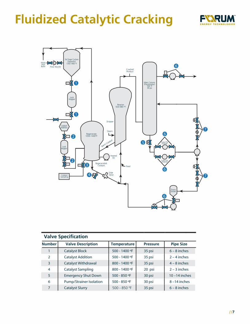
Fluidized Catalytic Cracking
3
1
1
2
23
36
36
36
36
37
3
35
4
Flow Nozzle
RegeneratedCatalyst
Stripper
Steam
Spent Catalyst
HeatedAir
Feed
Coke PotStrainer
CrackedProduct
WasteHeatBoiler
3rd Stage Cyclone(Separator)
1350-1400 °F
LockHopper
LockHopper
Regenerate1050-1400°F
Reactor920-980 °F
Main Column(Fractionator)
700 °F30 psi
SlurrySettler
CatalystSampling
CatalystAddition
37
Coke PotStrainer
Valve SpecificationNumber Valve Description Temperature Pressure Pipe Size
1 Catalyst Block 500 - 1400 ºF 35 psi 6 – 8 inches
2 Catalyst Addition 500 - 1400 ºF 35 psi 2 – 4 inches
3 Catalyst Withdrawal 800 - 1400 ºF 35 psi 4 – 8 inches
4 Catalyst Sampling 800 - 1400 ºF 20 psi 2 – 3 inches
5 Emergency Shut Down 500 - 850 ºF 30 psi 10 –14 inches
6 Pump/Strainer Isolation 500 - 850 ºF 30 psi 8 –14 inches
7 Catalyst Slurry 500 - 850 ºF 35 psi 6 – 8 inches
SlideValve
3
1
1
2
23
36
36
36
36
37
3
35
4
Flow Nozzle
RegeneratedCatalyst
Stripper
Steam
Spent Catalyst
HeatedAir
Feed
Coke PotStrainer
CrackedProduct
WasteHeatBoiler
3rd Stage Cyclone(Separator)
1350-1400 °F
LockHopper
LockHopper
Regenerate1050-1400°F
Reactor920-980 °F
Main Column(Fractionator)
700 °F30 psi
SlurrySettler
CatalystSampling
CatalystAddition
37
Coke PotStrainer
Valve SpecificationNumber Valve Description Temperature Pressure Pipe Size
1 Catalyst Block 500 - 1400 ºF 35 psi 6 – 8 inches
2 Catalyst Addition 500 - 1400 ºF 35 psi 2 – 4 inches
3 Catalyst Withdrawal 800 - 1400 ºF 35 psi 4 – 8 inches
4 Catalyst Sampling 800 - 1400 ºF 20 psi 2 – 3 inches
5 Emergency Shut Down 500 - 850 ºF 30 psi 10 –14 inches
6 Pump/Strainer Isolation 500 - 850 ºF 30 psi 8 –14 inches
7 Catalyst Slurry 500 - 850 ºF 35 psi 6 – 8 inches
SlideValve

8//
#1CokeDrum
#2CokeDrum
1
2
57
3 3
5
2
1
8
9
8
9
Purge Purge
Steam Steam
Overhead Vapor Line
CrudeHeater
Fractionator
Bottoms(Feed)
Metal-Seated Ball Valve Applications in Delayed Cokers
4 46 6
Valve SpecificationNumber Valve Description Temperature Pressure Pipe Size
1 Overhead Vapor 400 - 950 ºF 50 - 100 psi 6 – 8 inches
2 Steam Blowdown Control 400 - 950 ºF 50 - 100 psi 2 – 4 inches
3 Steam Warm-up 400 - 750 ºF 50 - 200 psi 4 – 8 inches
4 Quench Water 400 - 950 ºF
50 - 100 psi
50 - 200 psi
50 - 100 psi
50 - 100 psi
2000 psi
2 – 3 inches
5 Inlet Feed 400 - 950 ºF 10 –14 inches
6 Furnace Isolation 400 - 950 ºF 8 –14 inches
7
8
Switching
Cutting Water
400 - 950 ºF
Ambient
6 – 8 inches
2 – 6 inches
CuttingWaterPump
CuttingWaterPump
Delayed Coking
//9
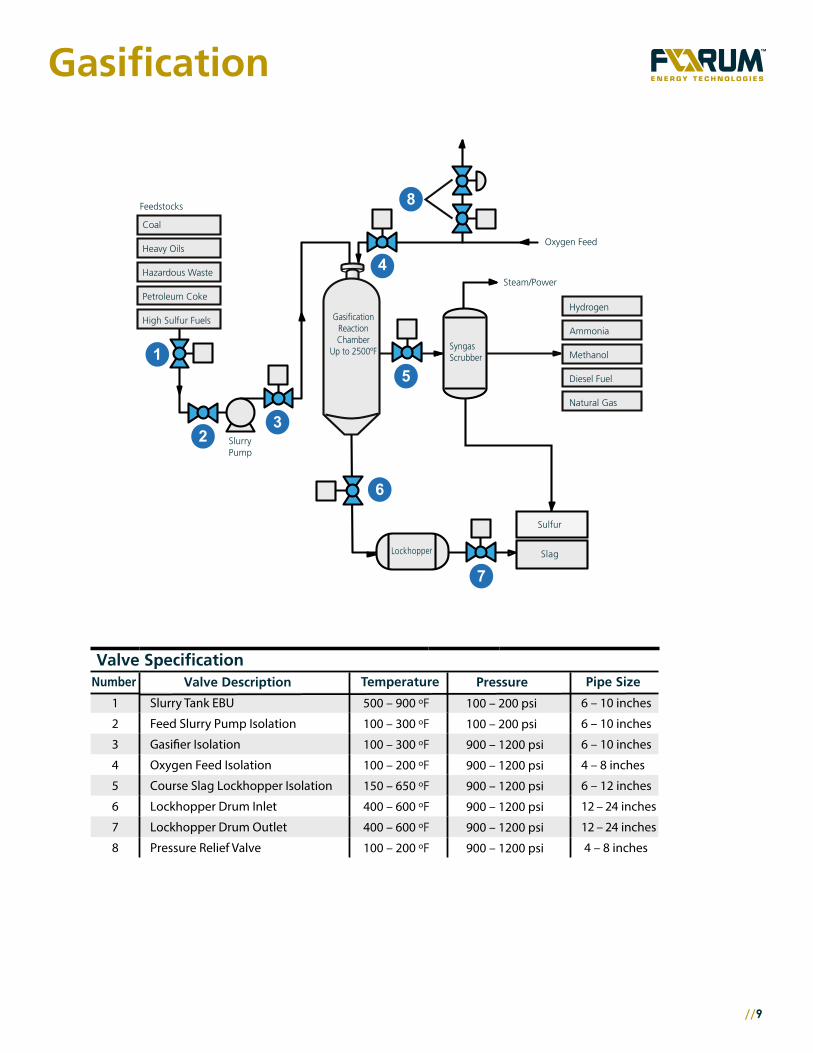
Gasification
Slag
23
4
Gasification
Valve SpecificationNumber Valve Description Temperature Pressure Pipe Size
1 Slurry Tank EBU 500 – 900 ºF 100 – 200 psi 6 – 10 inches
2 Feed Slurry Pump Isolation 100 – 300 ºF 100 – 200 psi 6 – 10 inches
3 Gasifier Isolation 100 – 300 ºF 900 – 1200 psi 6 – 10 inches
4 Oxygen Feed Isolation 100 – 200 ºF 900 – 1200 psi 4 – 8 inches
5 Course Slag Lockhopper Isolation 150 – 650 ºF 900 – 1200 psi 6 – 12 inches
6 Lockhopper Drum Inlet 400 – 600 ºF 900 – 1200 psi 12 – 24 inches
7 Lockhopper Drum Outlet 400 – 600 ºF 900 – 1200 psi 12 – 24 inches
8 100 – 200 ºF 900 – 1200 psi 4 – 8 inchesPressure Relief Valve
Feedstocks
GasificationReactionChamber
Up to 2500ºF
Lockhopper
Hydrogen
Ammonia
Methanol
Diesel Fuel
Natural Gas
Coal
Heavy Oils
Hazardous Waste
Petroleum Coke
High Sulfur Fuels
Steam/Power
Oxygen Feed
Sulfur
SyngasScrubber
SlurryPump
8
4
1
2
5
3
6
7Slag
23
4
Gasification
Valve SpecificationNumber Valve Description Temperature Pressure Pipe Size
1 Slurry Tank EBU 500 – 900 ºF 100 – 200 psi 6 – 10 inches
2 Feed Slurry Pump Isolation 100 – 300 ºF 100 – 200 psi 6 – 10 inches
3 Gasifier Isolation 100 – 300 ºF 900 – 1200 psi 6 – 10 inches
4 Oxygen Feed Isolation 100 – 200 ºF 900 – 1200 psi 4 – 8 inches
5 Course Slag Lockhopper Isolation 150 – 650 ºF 900 – 1200 psi 6 – 12 inches
6 Lockhopper Drum Inlet 400 – 600 ºF 900 – 1200 psi 12 – 24 inches
7 Lockhopper Drum Outlet 400 – 600 ºF 900 – 1200 psi 12 – 24 inches
8 100 – 200 ºF 900 – 1200 psi 4 – 8 inchesPressure Relief Valve
Feedstocks
GasificationReactionChamber
Up to 2500ºF
Lockhopper
Hydrogen
Ammonia
Methanol
Diesel Fuel
Natural Gas
Coal
Heavy Oils
Hazardous Waste
Petroleum Coke
High Sulfur Fuels
Steam/Power
Oxygen Feed
Sulfur
SyngasScrubber
SlurryPump
8
4
1
2
5
3
6
7
10//
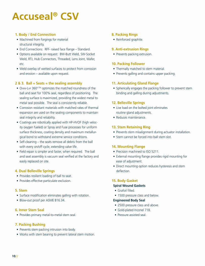
Accuseal® CSV
1. Body / End Connection • Machined from forgings for material
structural integrity.• End Connections: RFF- raised face flange – Standard.• Options available on request: BW-Butt Weld, SW-Socket
Weld, RTJ, Hub Connectors, Threaded, Lens Joint, Wafer, etc.
• Weld overlay of wetted surfaces to protect from corrosion and erosion – available upon request.
2 & 3. Ball + Seats = the sealing assembly• Omni-Lap 360o TM optimizes the matched roundness of the
ball and seat for 100% seal, regardless of positioning. The sealing surface is maximized, providing the widest metal to metal seal possible. The seal is consistently reliable.
• Corrosion resistant materials with matched rates of thermal expansion are used on the sealing components to maintain seal integrity and reliability.
• Coatings are robotically applied with HP-HVOF (high veloc-ity oxygen fueled) or Spray and Fuse processes for uniform surface thickness, coating density and maximum metallur-gical bond to withstand extreme service conditions.
• Self-cleaning – the seats remove all debris from the ball with every on/off cycle, extending valve life.
• Field repair is simpler and faster, when required. The ball and seat assembly is vacuum seal verified at the factory and easily replaced on site.
4. Dual Belleville Springs• Provides resilient loading of ball to seat. • Provides effective particulate exclusion.
5. Stem • Surface modification eliminates galling with rotation.• Blow-out proof per ASME B16.34.
6. Inner Stem Seal• Provides primary metal-to-metal stem seal.
7. Packing Bushing• Prevents stem packing intrusion into body.• Works with stem bearing to prevent lateral stem motion.
8. Packing Rings• Reinforced graphite.
9. Anti-extrusion Rings• Prevents packing extrusion.
10. Packing Follower• Thermally matched to stem material.• Prevents galling and contains upper packing.
11. Articulating Gland Flange• Spherically engages the packing follower to prevent stem
binding and galling during adjustments.
12. Belleville Springs • Live load on the bolted joint eliminates
routine gland adjustments.• Reduces maintenance.
13. Stem Retaining Ring• Prevents stem misalignment during actuator installation.• Stem cannot be forced into ball stem slot.
14. Mounting Flange• Precision machined to ISO 5211.• External mounting flange provides rigid mounting for
ease of adjustment.• Direct mounting option reduces hysteresis and stem
deflection.
15. Body GasketSpiral Wound Gaskets• Grafoil filled.• 1500 pressure class and below.
Engineered Body Seal• 2500 pressure class and above.• Gold-plated Inconel 718.• Pressure assisted seal.

//11
Articulating G
land Fla
nge
Preferred Flow Direction
ACCUSEAL® CSV SHOWN ABOVE: FLANGED SEAT DUAL SPRINGS
1
2
3
3
44
5
67
89
101112
13 14
15
Unidirectional flow• Flanged seat design.• Sharp leading edges of the seat scrape
the ball clean each time the valve is opened.
• Fully field service-able.• Vacuum tested to Class VI shutoff.
Bidirectional• Locked-in downstream seat.• Fully bidirectional - completely independent
of flow direction.• Redundant isolating seats - both upstream
and downstream seat are in continuous sealing engagement with ball.
Dual Belleville load springs provide effective particulate exclusion of critical annular area between load ring and body.
Dual Spring• Upstream Seat Landing is mate lapped to
upstream landing for bi-directional seat.• Line contact at the O.D. and I.D provides a
particulate barrier protecting the landing.
Various Seating Options Available per Application
12//
Accuseal® Critical Service Ball Valve
Applications• Critical isolation of Slurry, Liquids, Solids, and Gases• Custom designs to solve problematic applications
Any application with service conditions too hot and/or abrasive/erosive for commodity valves
Features and Benefits• Flow Isolation Options
• Unidirectional – Standard• Bidirectional – Shuts off flow in either direction
• Positive mechanical stops prevent over-travel• Operator – Per application requirements• Easily automated with ISO 5211 standard mounting pads• Self-cleaning ball and seats• Positive positioning feature prevents misalignment during actua-
tion. Stem cannot force ball out of correct position• Field repairable with Omni-Lap 360o TM ball and seat assemblies,
vacuum seal pretested at the factory 1 year warranty standard (contact Forum Accuseal® for details)
Bidirectional with Preferred Flow• Size: ½”- 36” • Full and reduced port valves • Bore to match pipe ID – available• ASME Pressure Class: 150 thru 4500
Materials of Construction• A105, Stainless Steel, Exotic Alloys and other
materials by request.
End Connections• RFF Standard or to customer
specifications (Butt Weld, Socket Weld, RTJ, Hub Connectors, Threaded)
Actuator Options • Factory installation of actuator of your
choice• Mounting kits provided to mount to
existing actuators
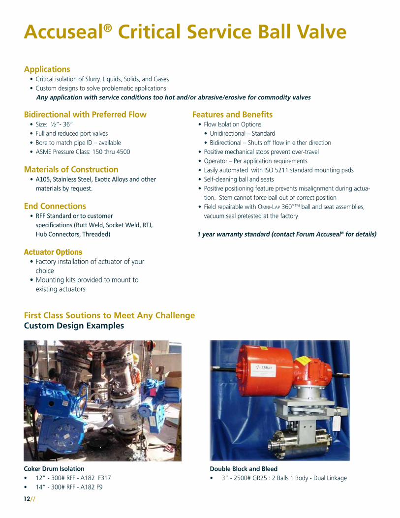
Coker Drum Isolation• 12” - 300# RFF - A182 F317• 14” - 300# RFF - A182 F9
Double Block and Bleed• 3” - 2500# GR25 : 2 Balls 1 Body - Dual Linkage
First Class Soutions to Meet Any ChallengeCustom Design Examples
//13
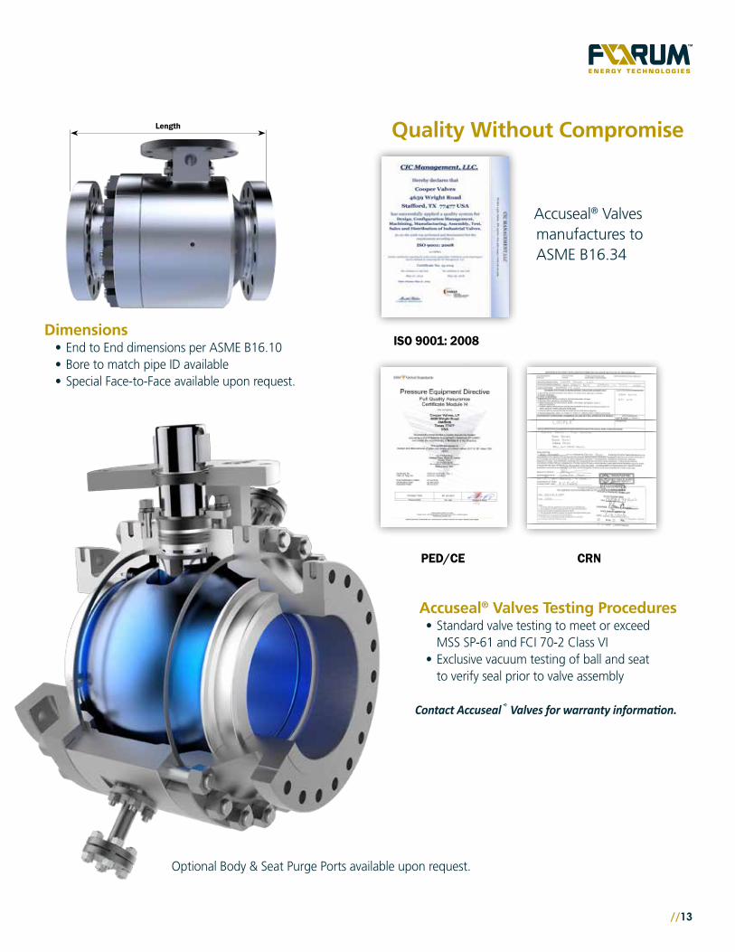
Length Quality Without Compromise
Accuseal® Valves manufactures to ASME B16.34
Accuseal® Valves Testing Procedures• Standard valve testing to meet or exceed
MSS SP-61 and FCI 70-2 Class VI• Exclusive vacuum testing of ball and seat
to verify seal prior to valve assembly
Contact Accuseal® Valves for warranty information.
ISO 9001: 2008
CRNPED/CE
Dimensions• End to End dimensions per ASME B16.10• Bore to match pipe ID available • Special Face-to-Face available upon request.
Optional Body & Seat Purge Ports available upon request.
Copyright © FORUM ENERGY TECHNOLOGIES, INC. All rights reserved • ACCUSEAL_Hydrocarbon_Processing_REV050117 • Stafford, USA
Our goal is to become the leading provider of mission critical oilfield products and related services in terms of customer satisfaction, safety and financial performance.
Our experienced management team and employees are dedicated to solving our customers’ problems. We invest in long term relationships and cooperate on product development with our clients, we consider them our partners.
OUR CORE VALUES
Integrity: In everything we do, in every interaction, both internally and externally, we strive to operate with the upmost integrity and mutual respect.
Long-term view: We are building our company for the long-term, a company that we can be proud of.
Open communication: We believe partnerships with our customers and co-workers must be based on trust, professionalism and transparency.
Customer focused: Our products enhance our customer’s performance and we listen to their needs and work with them to solve their challenges.
Good place to work: We are committed to creating a workplace that fosters innovation, teamwork and pride. Every team member is integral to our success and is treated equally and fairly.
No one gets hurt: The safety of our employees and customers is our first priority coupled with a healthy respect for the environment.
12735 Dairy Ashford RoadStafford, Texas 77477281.637.2000 [m] 800.256.6193 [tf] 281.340.5499 [f]www.f-e-t.com
For more information about our products and full Terms & Conditions please visit www.f-e-t.com.