Accurate and Efficient Simulation of Fracture–Matrix...
16
Transp Porous Med (2015) 107:305–320 DOI 10.1007/s11242-014-0437-x Accurate and Efficient Simulation of Fracture–Matrix Interaction in Shale Gas Reservoirs Long Cai · Didier-Yu Ding · Cong Wang · Yu-Shu Wu Received: 2 May 2014 / Accepted: 5 December 2014 / Published online: 16 December 2014 © Springer Science+Business Media Dordrecht 2014 Abstract Gas production from low-permeability shale formations relies on natural or man- made fractures for gas flow pathways to production wells. Shale gas reservoir simulation includes fracture–matrix flow and fracture–matrix interactions as they are key. Attention has focused on modeling fractures in shale gas production, yet there have been few studies carried out to address how to accurately simulate fracture–matrix interaction in unconven- tional low-permeability gas reservoirs. The classic double porosity model and the MINC method represent studies designed to accurately simulate fracture–matrix interaction; how- ever, methods continue to encounter issues causing them to fall short of the accuracy sought. Applicability of the classic double porosity model with a constant shape factor to low- permeability reservoir simulation is questionable and has not been validated as the required pseudo-steady-state flow condition timing may not sufficiently satisfy shale gas reservoirs. The MINC method treats inter-porosity flow in a fully transient mode by further subdividing individual blocks with a number of 1-D nested meshes. The MINC concept, however, assumes that fracture–matrix flow is controlled only by the distance to the nearest fracture surround- ing the matrix block and is shown to be no longer applicable after the early rapid transient period of fracture–matrix flow. A comparative investigation of commonly used fractured reservoir simulation approaches for applicability to fracture–matrix interaction in unconven- tional reservoirs is presented in this paper. A new nested subdividing concept, referred to as the Schwarz–Christoffel conformal mapping approach, will be introduced. The new method is able to accurately and efficiently simulate the matrix–fracture interaction for the entire tran- L. Cai (B ) · C. Wang · Y.-S. Wu Department of Petroleum Engineering, Colorado School of Mines, Golden, CO, USA e-mail: [email protected] C. Wang e-mail: [email protected] Y.-S. Wu e-mail: [email protected] D.-Y. Ding IFP Energies Nouvelles, Rueil Malmaison, France e-mail: [email protected] 123
Transcript of Accurate and Efficient Simulation of Fracture–Matrix...

Transp Porous Med (2015) 107:305–320DOI 10.1007/s11242-014-0437-x
Accurate and Efficient Simulation of Fracture–MatrixInteraction in Shale Gas Reservoirs
Long Cai · Didier-Yu Ding · Cong Wang · Yu-Shu Wu
Received: 2 May 2014 / Accepted: 5 December 2014 / Published online: 16 December 2014© Springer Science+Business Media Dordrecht 2014
Abstract Gas production from low-permeability shale formations relies on natural or man-made fractures for gas flow pathways to production wells. Shale gas reservoir simulationincludes fracture–matrix flow and fracture–matrix interactions as they are key. Attentionhas focused on modeling fractures in shale gas production, yet there have been few studiescarried out to address how to accurately simulate fracture–matrix interaction in unconven-tional low-permeability gas reservoirs. The classic double porosity model and the MINCmethod represent studies designed to accurately simulate fracture–matrix interaction; how-ever, methods continue to encounter issues causing them to fall short of the accuracy sought.Applicability of the classic double porosity model with a constant shape factor to low-permeability reservoir simulation is questionable and has not been validated as the requiredpseudo-steady-state flow condition timing may not sufficiently satisfy shale gas reservoirs.The MINC method treats inter-porosity flow in a fully transient mode by further subdividingindividual blocks with a number of 1-D nested meshes. The MINC concept, however, assumesthat fracture–matrix flow is controlled only by the distance to the nearest fracture surround-ing the matrix block and is shown to be no longer applicable after the early rapid transientperiod of fracture–matrix flow. A comparative investigation of commonly used fracturedreservoir simulation approaches for applicability to fracture–matrix interaction in unconven-tional reservoirs is presented in this paper. A new nested subdividing concept, referred to asthe Schwarz–Christoffel conformal mapping approach, will be introduced. The new methodis able to accurately and efficiently simulate the matrix–fracture interaction for the entire tran-
L. Cai (B) · C. Wang · Y.-S. WuDepartment of Petroleum Engineering, Colorado School of Mines, Golden, CO, USAe-mail: [email protected]
C. Wange-mail: [email protected]
Y.-S. Wue-mail: [email protected]
D.-Y. DingIFP Energies Nouvelles, Rueil Malmaison, Francee-mail: [email protected]
123
306 L. Cai et al.
sient flow by combining the MINC and Schwarz–Christoffel conformal mapping conceptsof gridding inside the matrix. The theoretical development, benchmarking, and applicationof the new modeling approach explanations follow.
Keywords Double porosity model · MINC · Schwarz–Christoffel conformal mapping ·Analytical solution · Shale gas reservoir simulation
Lists of Symbols
A Interface area of fracture–matrix (m2)ct Total gas compressibility coupled with gas sorption term (Pa−1)D Distance between flow potentials (m)L Dimension of the block (m)mg Gas sorption term (kg/m3)k, km, kg Permeability, permeability of matrix, and gas permeability (m2)PL Langmuir isotherm pressure (Pa)Pm, Pf Gas pressure at matrix and fracture, respectively (Pa)Pm,b Gas pressure at matrix coupled with the Klinkenberg effect (Pa)P̄m,b Averaged gas pressure at matrix coupled with the Klinkenberg effect (Pa)Pi Gas pressure at initial condition (Pa)q Sink/source term (kg/(m3 s))r Distance from the block center at radial direction (m)t Time (s)T Transmissibility term between two blocksv Velocity of fluid (m/s)VL Langmuir volume (m3/kg)Vm Volume of block (m3)∅,∅m Porosity, matrix porosityρ Density of the fluid (kg/m3)ρg Gas density at standard condition (kg/m3)ρR Rock bulk density at standard condition (kg/m3)β Gas density-related coefficient (kg/(m3 Pa))μ Viscosity of gas (Pa s)σ Shape factor (1/m2)
Subscripts
f Fractureg Gasi Initial conditioni, j Blocks i and jm Matrixx, y, z x, y, z-coordinate direction
123

Fracture–Matrix Interaction in Shale Gas Reservoirs 307
1 Introduction
The matrix provides most of the pore volume for storage in fractured reservoirs and con-tributes little to the global flow, while the fracture supplies the flow or transmissivity withnegligible contributions to reservoir porosity. Barenblatt et al. (1960) and by Warren andRoot (1963) introduced the dual-porosity model which treats a naturally fractured reservoirwith irregular matrix, vugs and fractures as an equivalent, homogeneous model. Compared toconventional reservoirs, gas production in ultra-low-permeability unconventional reservoirsis driven by highly non-linear flow equations (Wu et al. 2014), such as the gas Klinken-berg effect (e.g., Javadpour 2009), high gas compressibility, and adsorption and desorptionon organic surfaces (e.g., Sigal et al. 2013; Javadpour et al. 2007). Gas production drivenby non-linear flow equations involves several processes due to the presence of multi-scalefracture network, and the heterogeneous nature of a porous/fractured and stress-sensitiverock.
Several conceptual models have been developed to model fracture–matrix interactionfor flow in fractured porous media. Models share the same scheme, but possess differentassumptions or concepts dealing with flow inside the matrix. Explicitly dividing the matrixand fractures utilizing the discrete fracture model is an accurate option, but is limited in fieldscale simulation. The discrete fracture model generally requires an exceptional number ofgrid blocks to represent matrix and fracture systems, increasing the computational cost (Gongand Qin 2012). Lack of detailed knowledge for fracture and matrix geometric properties andtheir spatial distributions at given subsurface sites necessitates multiple realizations, renderingexplicit fracture simulations nearly impossible for field application.
The classic double porosity model may not be applicable in a shale gas reservoir simulationas transient flow may be long lasting. Efforts to improve transient flow have been establishedas Pruess and Narasimhan (1982, 1985) defined a Multiple Interacting Continuum (MINC)method to improve the transient flow simulation; however, when the flow stabilizes, an erroroccurs. Pruess and Wu (1989) introduced a semi-analytical solution utilizing a trial functiondeveloped by Vinsome and Westerveld (1980) to estimate the pressure distribution in a matrixblock when simulating slightly compressible fluid flow. Zimmerman et al. (1993) introducedanother type of semi-analytical treatment of fracture/matrix flow using a non-linear ordinarydifferential equation to calculate interaction term. Sarma and Aziz (2006) derived a time-dependent shape factor for simulation of naturally fractured reservoirs. Lu et al. (2008)introduced transfer functions for multiphase flow in fractured reservoirs that captures fluidexpansion, diffusion, and displacement. Improvements to the classical double model havebeen accomplished as a result of these efforts. Challenges in shale gas reservoir simulationpersist, however, in determining integral solutions dealing with the gas compressibility term,the gas Klinkenberg effect, and sorption term. Non-linear physics of the shale gas reservoirdesign do not allow for the derivation of an accurate form of analytical solutions. Karimi-Fardet al. (2006) proposed a subgridding technique which is constructed numerically by usingiso-pressure surfaces of fine grid pressure solution. Ding et al. (2014) verified the iso-pressuremethod combined with the MINC method being accurate in shale gas reservoir simulation,but advance iso-pressure surface generation was inefficient.
The flow behavior in a single square/cubical node is analyzed to determine methodsfor accurately handling flow from the matrix to the surrounding fracture and to understandcritical issues affecting gas recovery from the matrix. Four model types are discussed, theclassic double porosity model, the MINC model, the Schwarz–Christoffel conformal mappingapproach, and the method combining the MINC and the Schwarz–Christoffel conformalmapping approach. The combined MINC and the Schwarz–Christoffel mapping approach
123

308 L. Cai et al.
method demonstrates a significant improvement to the classic double porosity model and theMINC method.
2 Mathematical Model
Flow behavior in shale gas reservoirs is characterized by single gas phase or multiphase (gas,gas condensate, and/or brine). Wu et al. (2014) presented the mass balance equation of shalegas flow in an arbitrary flow region of a porous or fractured unconventional low-permeabilityreservoir. Models are tested only in single gas phase flow condition for purposes of this paper.The mass balance equation can be simplified as follows:
∂
∂t
(∅ρ + mg) = −∇ · (ρv) + q, (2.1)
where mg is the gas sorption term utilizing the Langmuir isotherm equation to accountfor the gas adsorbed/desorbed on the solid surface (Langmuir 1916); the Klinkenberg effect(Klinkenberg 1941) is considered as a contribution to the permeability by modifying absolutepermeability for the gas phase as a function of gas pressure in the velocity term v (Wu et al.1998).
2.1 Classic Double Porosity Model
The classic double porosity model with a shape factor is widely employed in conventionalnaturally fractured reservoir simulation, but is valid only when flow turns stable or reachespseudo-steady state. Warren and Root (1963), Kazemi et al. (1976), and many others (e.g.,Coats 1989; Thomas et al. 1983) provided shape factors for the model. Lim and Aziz (1995)derived a shape factor from an analytical solution of liquid flow in a porous medium, andMathias and Zimmerman (2003) verified the factor in the Laplace domain for liquid flow.An analytical solution for gas flow in a square (cubic) system is derived with two majorassumptions: flow is approximated in a square/cubical system to radial/spherical flow, andthe sorption term is linearized on the right-hand-side (RHS) of the governing equation. Thesame shape factors can be derived for shale gas flow when the same treatment derived by Limand Aziz (1995) is applied for the analytical solution. Shape factors verified in this paper aresummarized in Table 1.
2.2 MINC Model
Pruess and Narasimhan (1982, 1985) presented the MINC theory to improve the simulation oftransient flow. The theory assumes that the fracture–matrix flow is controlled by the distanceto nearest fractures only. Under this assumption, the matrix is divided into a set of nestedsub-blocks and, for a square/cubical system, the sub-blocks are square/cubic. The MINCmodel is accurate if the flow potential at each sub-block can be represented by the pressure at
Table 1 Summary of the shape factors for two/three-dimensional system derived from various authors
Dimension Warren and Root (1963) Kazemi et al. (1976) Lim and Aziz (1995)
2 32/L2 8/L2 18.17/L2
3 60/L2 12/L2 25.67/L2
123

Fracture–Matrix Interaction in Shale Gas Reservoirs 309
Fig. 1 Schematic of different inter-porosity flow concepts a explicit discretization b nested discretizationc double porosity discretization (Wu and Pruess 1988)
the center of each block. The schematics of the MINC and the double porosity discretizationare illustrated in Fig. 1.
2.3 Schwarz–Christoffel Conformal Mapping Approach
Fluid flow in matrices is driven by potential gradient and moves in the downward directionof the potential field. As in a disk-shaped matrix, flow streamlines are rays from the origin,and the orthogonal equipotential lines are concentric and homothetic to the disk boundary.The orthogonal field consists of fluid flow streamlines and equipotential curves. Schwarz–Christoffel conformal mapping can transfer the orthogonal field in the disk shape into anyother polygons. The Schwarz–Christoffel transformation is widely utilized in the potentialtheory and its applications, including minimal surfaces and fluid dynamics, most notablythose utilizing the 2D Laplace equation. The Schwarz–Christoffel mapping is a conformaltransformation of the upper half-plane into a polygon (e.g., Driscoll 1996, 2005; Delillo etal. 2006). The Riemann mapping theorem, with consideration of a polygon in a complexplane, implies there exists a one-to-one conformal mapping that is capable of mapping theupper half-plane to the polygon.
2.3.1 Schwarz–Christoffel Mapping Mesh Generation
The transformation is non-linearly constrained along the side of the target polygon. Axesof symmetry are initially mapped to determine the vertexes, as symmetry is advantageousfor reducing computational work. Consequently, the outer boundary can be determined, andintegration can occur along different rays from the disk to the square. Mapped curves nowrepresent flow streamlines in the square system, and concentric circles are able to be latermapped to the square. Perpendicularity in the disk system is kept on the square system, asdisplayed in Fig. 2.
Sub-blocks near the boundary are controlled more by the fracture, and the shape resemblesa square (but is not square). The location away from the fracture creates sub-block more likea circle than a square. Schwarz–Christoffel mapping is an applicable theory on the 2-D planeand can be extended to 3-D according to the symmetry, as illustrated in Fig. 3.
2.3.2 Transmissibility Calculation between Neighboring Sub-Blocks
Generation of the sub-block by using the Schwarz–Christoffel mapping essentially followsthe MINC theory (Pruess 1983). Block number and the volume fractions of each sub-block are
123

310 L. Cai et al.
Fig. 2 Schematic of the Schwarz–Christoffel mapping from disk shape onto the square system: rays from theorigin represent the flow streamlines, and concentric curves represent the iso-pressure curves
Fig. 3 Schematic of theSchwarz–Christoffel mappingnested blocks of athree-dimensional systemextended from the 2-D system(blue curves on each plane)
predefined, and utilize an iterative method to identify the sub-block boundaries (Pruess et al.1999). The Schwarz–Christoffel mapping provides coordinate values of all the points in theinterface allowing the interface area to be determined by a summation method. The distancebetween two sub-blocks is determined by the interface area and the sub-block volumes. Fluxbetween two-block is governed by the transmissibility term, and the transmissibility betweentwo gird blocks is calculated with a weighted harmonic average as
Ti j = Ai jki k j
D j ki + Di k j, (2.2)
where Ai j is the area of the interface between the blocks i and j ; Di and D j are, respectively,the distances from the block centers i and j to their interface; ki and k j are, respectively, theabsolute permeability along the direction toward the interface in the blocks i and j .
123

Fracture–Matrix Interaction in Shale Gas Reservoirs 311
Fig. 4 Schematic of the MINCcombines theSchwarz–Christoffel ConformalMapping Concepts: MINC nestedelements from the exterior totransition location “D” and theSchwarz–Christoffel mappingelements from “D” to the centerof the block
2.4 MINC Combines the Schwarz–Christoffel Conformal Mapping Concepts(MINC-SCCM)
The MINC concept assumes that fracture–matrix flow is controlled only by the distance tothe nearest fracture surrounding the matrix block, indicated as integral to the early rapidtransient period of fracture–matrix flow for the MINC solution to remain combined withthe true solution (Fig. 7). Early in the flow, the matrix has not been fully penetrated, andthe inner portion of the matrix acts as an infinite source feeding the outer portion. Duringearly production, pressure behavior resembles it in an infinite reservoir (Matthews 1986).The Schwarz–Christoffel conformal mapping concept, however, divides the matrix based onthe theory of flow potential and is indicated to apply following the early rapid transient period(Fig. 7).
Proceeding with the concept of the MINC concept in early stages and switching to theSchwarz–Christoffel conformal mapping concepts after the early transient flow period seemto be a clear step. However, this method is complicated to implement. A semi-analyticalsolution for matrix–fracture flow has utilized a concept referred to as penetration depth(where penetration depth and time are equivalent) for a pressure disturbance at the blocksurface thus, a function of time at certain reservoir conditions (e.g., Pruess and Wu 1989;Moridis 2002). Considering this solution, a method is introduced dividing the outer portionof the matrix utilizing the MINC concept, while the inner portion is divided on the theory ofthe Schwarz–Christoffel mapping concept (Fig. 4).
2.4.1 Transition Location from the MINC to the Schwarz–Christoffel MappingConcept Determination
The transition “D”, which is a distance from the block surface, from the MINC to the Schwarz–Christoffel mapping concept is determined by the Darcy velocity law and the shape factor,as determined by an analytical solution. The analytical solution describes the flow insidethe matrix block in a fully transient way (Appendix). Though the classic double porositymodel is not accurate in shale gas simulation, the analytical solution derived Lim and Azizshape factors (Eqs. 5.20, 5.23), which nearly match the reference solutions when flow turnsstabilize (Fig. 6). The MINC concept may be applied to divide the matrix from the block
123

312 L. Cai et al.
surface to the location “D”, and the Schwarz–Christoffel mapping concept may be appliedto divide the remaining matrix. In the double porosity model, mass out of the matrix equalsmass flowing into the fracture, or vice versa. Consider gas flow rate for a linear system withPm at the inlet and Pf at the outlet. The linear flow equation can be written as follows forcompressible gas flow according to the Darcy’s law:
q = βkg A
2μ
(P2m − P2
f )
D. (2.3)
In the two-dimensional system, interface area between the matrix and the fracture is A = 4L2;D indicates the potential distance from the matrix to the fracture; β is a gas density-relatedcoefficient, defined as β = M/Z RT . The classic double porosity model calculates the inter-porosity transfer rate to be proportional to the pressure difference between the matrix andthe fracture, based on the pseudo-steady-state flow assumption (Warren and Root 1963). Theresulting transfer rate between the matrix and the fracture in a control volume produces theequation below:
q = σ · βkg
2μ
(P2
m − P2f
)Vm. (2.4)
Substitute Lim and Aziz shape factor (Eq. 5.18) to Eq. 2.4, and equal to Eq. 2.3, leading to
D = 4
18.17L . (2.5)
Note that, D (Eqs. 2.5, 2.6) provides only an approximate location of the potential center andis not a factor in direct calculation. Slight errors originating from assumptions to “D” areacceptable. The transition distance from the fracture obtained from the analytical solution(use Eqs. 5.23, 2.3 and 2.4) for the cubical system with three sets of fracture calculated by
D = 6
25.67L . (2.6)
3 Results and Analysis
Concept evaluation utilizes a single node system for its simplified structure and limitedvariables. Pure methane single-phase gas flow in a square/cubical system is calculated takinginto account Darcy flow, gas sorption on the solid surface, and the Klinkenberg effect. Thelow-permeable square-shaped matrix is connected to two/three sets of conductive fractures(Table 2), while fracture pressure remains constant at 3.45E06 Pa and system dimension is10 m. Prevention and/or reduction of inconsistencies were minimized by keeping the numberof sub-blocks in a matrix and the volumes of each sub-block the same in all nested cases. Caseswith 5, 10, and 35 sub-blocks were tested, and in some cases, sub-blocks were even increasedto 100. Although there is a lack of rigorous proofs, the numerical results move toward the truesolution as the number of sub-blocks increases. An important result revealed that errors in theMINC model or the Schwarz–Christoffel mapping model cannot be completely eliminatedby raising the sub-block number. Results of cases with 10 sub-blocks are presented in thispaper.
The reference solution in Fig. 6 is obtained by fine grid simulation utilizing the MSFLOW-UG simulator (Wu 2012). In the two-dimensional case, the matrix is divided into 48 segmentsin both X and Y directions with only one layer in Z direction. In the three-dimensional case,
123
Fracture–Matrix Interaction in Shale Gas Reservoirs 313
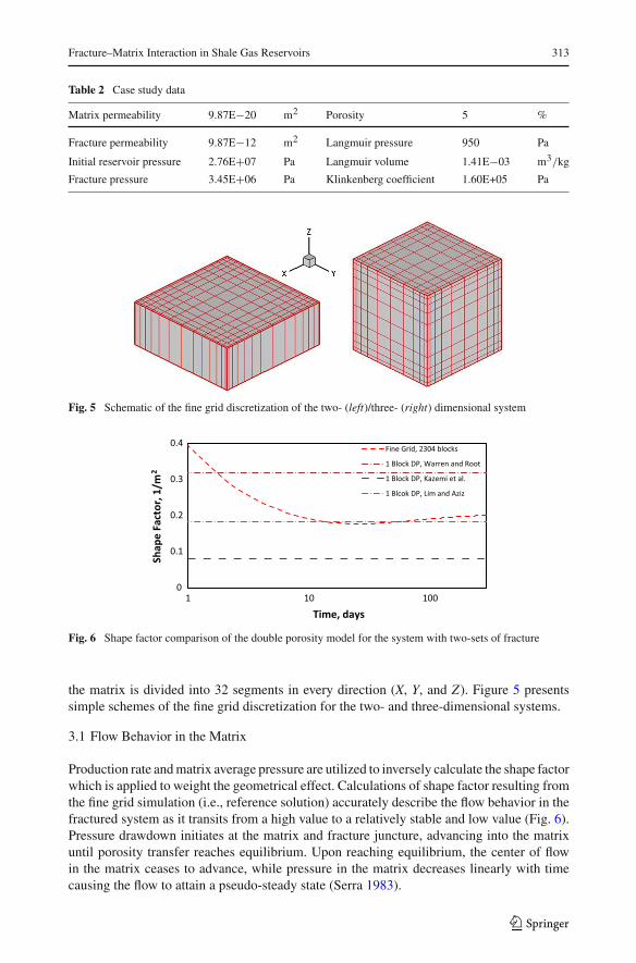
Table 2 Case study data
Matrix permeability 9.87E−20 m2 Porosity 5 %
Fracture permeability 9.87E−12 m2 Langmuir pressure 950 Pa
Initial reservoir pressure 2.76E+07 Pa Langmuir volume 1.41E−03 m3/kg
Fracture pressure 3.45E+06 Pa Klinkenberg coefficient 1.60E+05 Pa
Fig. 5 Schematic of the fine grid discretization of the two- (left)/three- (right) dimensional system
0
0.1
0.2
0.3
0.4
1 10 100
Shap
e Fa
ctor
, 1/m
2
Time, days
Fine Grid, 2304 blocks
1 Block DP, Warren and Root
1 Block DP, Kazemi et al.
1 Blcok DP, Lim and Aziz
Fig. 6 Shape factor comparison of the double porosity model for the system with two-sets of fracture
the matrix is divided into 32 segments in every direction (X, Y, and Z). Figure 5 presentssimple schemes of the fine grid discretization for the two- and three-dimensional systems.
3.1 Flow Behavior in the Matrix
Production rate and matrix average pressure are utilized to inversely calculate the shape factorwhich is applied to weight the geometrical effect. Calculations of shape factor resulting fromthe fine grid simulation (i.e., reference solution) accurately describe the flow behavior in thefractured system as it transits from a high value to a relatively stable and low value (Fig. 6).Pressure drawdown initiates at the matrix and fracture juncture, advancing into the matrixuntil porosity transfer reaches equilibrium. Upon reaching equilibrium, the center of flowin the matrix ceases to advance, while pressure in the matrix decreases linearly with timecausing the flow to attain a pseudo-steady state (Serra 1983).
123

314 L. Cai et al.
0
0.1
0.2
0.3
0.4
1 10 100
Shap
e Fa
ctor
, 1/m
2
Time, days
Fine Grid 2304 Blocks
10 Blocks Schwarz-Christoffel
10 Blocks MINC
10 Blocks MINC-SCCM
Fig. 7 Shape factor comparison of the nested sub-blocks model for the system with two-sets of fractures(shape factor is calculated by production rate and average matrix pressure)
Based on the pseudo-steady-state flow assumption with application of a constant shapefactor, the double porosity model neglects transient flow behavior and does not adequatelymanage the matrix–fracture interaction. The double porosity model with Warren and Rootor Kazemi et al.’s shape factors, even under the stable flow conditions, do not adequatelycompare to the reference solution (Fig. 6). In contrast, the Lim and Aziz shape factor nearlymatches the reference solution upon flow stabilization (Fig. 6), which indicates the analyticalsolutions are accurately acceptable.
3.2 Results Analysis of Nested Sub-Blocks Cases
The MINC model’s solution closely aligns with the reference solution at early times (Fig. 7),subsequently diverging following early transient flow and, finally not converging to the “true”solution with refinement of block subdivision. The MINC subdivides only in the X, Y, andZ directions toward the block boundary thus, the circular direction around the ring is notpreserved. Comparatively, the Schwarz–Christoffel mapping approach is superior to boththe double porosity and MINC models at later times. Errors in early stages of the Schwarz–Christoffel mapping approach, however, limit the overall advantages. The ability to eliminateearly stage errors with a refinement of the block is prevented due to the square shape of theiso-pressure curves other than the Schwarz–Christoffel conformal mapping shapes (e.g., Cai2014; Ding et al. 2014).
The MINC model and the Schwarz–Christoffel mapping model are accurate at differenttimes. The MINC-SCCM combination model takes advantage of both concepts and can accu-rately handle the gas flow in the matrix for the entire production period (Fig. 7). Cumulativeproduction curves (Fig. 8) also indicate the precise work of the MINC-SCCM combination.Shape factors and cumulative gas production from the three-dimensional case are not plottedin this paper, because they do not deviate from patterns of the two-dimensional case (moreplots can be found in Cai 2014).
4 Discussion
Transient flow regimes may be prolonged in shale gas reservoirs, and the widely used classicaldouble porosity model may not be applicable in the shale gas reservoir simulation. Fracture–matrix flow simulated by 1D MINC flow with the nested sub-blocks design was introduced
123

Fracture–Matrix Interaction in Shale Gas Reservoirs 315
0E+0
5E+3
1E+4
0 50 100
Cum
ula�
ve P
rodu
c�on
, m3
Time, days
Fine Grid 2304 Blocks
10 Blocks Schwarz-Christoffel
10 Blocks MINC
10 Blocks MINC-SCCM
1 Block DP, Lim and Aziz
Fig. 8 Cumulative production of the nested sub-block model and the double porosity model of system withtwo-sets of fractures
by Pruess and Narasimhan. The theory of the MINC approach is simple, and computationallyacceptable with pressure behavior essentially emulating that in infinite reservoirs. Flow iscontrolled only by the nearest fracture with flow streamlines along axes, which follows theMINC assumptions, making the MINC concept more suitable for the discretization of thematrix outer portion.
Flow streamlines begin to radiate out from the block center rather than along the axes as gasis produced from the reservoir following the initial transient period. This alteration in flowstreamlines derails perpendicularity with the iso-pressure curves and effective applicationof the MINC concept as flow does not converge with the correct solution. Preservation ofperpendicularity following the initial transient stage is pursued via the Schwarz–Christoffelmapping concept. The Schwarz–Christoffel conforming model is applied to stabilize flow,thus retaining perpendicularity. The transition from the MINC concept to the Schwarz–Christoffel conforming mapping model occurs in a transition location as determined by ananalytical solution.
Transition location “D” is determined by an analytical solution with flow in the matrixdescribed in a fully transient way. Two major assumptions exist in the derivation process:approximate the flow in a square/cubical system to a cylindrical/spherical flow and linearizethe pressure term on the right side of the governing equation. The simplified analytical solutionutilizes only the first term of the infinite summation series to produce an approximate solutionfor identifying transition location “D.” Approximating transition location “D” is acceptableas “D” is not imperative in calculations thus, does not affect node discretization. Combiningthe MINC and Schwarz–Christoffel mapping concept methods allows characterization ofmajority flow at different times while defining precision flow processes during the entire flowperiod. The combination operates to maximize advantages of both methods for attainmentof accurate results (Fig. 8).
5 Summary and Conclusions
This paper summarizes current major matrix–fracture interaction modeling concepts, intro-duces a new nested subdividing concept, evaluates several models at shale gas reservoirconditions, and recommends a combination method. Limitations of the classic double poros-ity model, the MINC model, and the Schwarz–Christoffel conformal mapping concept are
123

316 L. Cai et al.
discussed. In shale gas reservoirs, flow may become stable or reach a pseudo-steady stateafter a long period of transient flow due to the low matrix permeability inherent to thesereservoirs, the Klinkenberg effect, and the sorption of as molecules in the matrix. The classicdouble porosity model does not take into account simulation of the transient flow, resultingin a significant error in the early transient flow stage. Transient flow is negligible short inconventional reservoirs and the classic double porosity model functions accurately. Shale gasreservoirs, characterized by low matrix permeability, experience significantly prolonged anddistinct flow regimes. Transient and stable flow periods must both be fully addressed to ade-quately manage the flow in such a reservoir. The MINC model and the Schwarz–Christoffelconformal mapping model do not fully consider the flow characteristics at different timesand are not sufficient to manage the shale gas reservoir simulation. Combining the MINCand Schwarz–Christoffel mapping concepts of gridding inside the matrix allows majorityflow characterization at different times and is able to accurately and efficiently simulate thematrix–fracture interaction for the entire transient flow. The block is discretized with MINCnested elements from the exterior to an analytically derived transition location (“D”), fromthis location to the center of the block, the Schwarz–Christoffel conformal mapping approachis applied to complete the task.
Extensively used models include idealized blocks, i.e., square and rectangular shapeblocks, but the MINC concept, as well as the Schwarz–Christoffel mapping concept, canbe extended to any arbitrary polygonal shape in theory. The feasibility of methods appliedin other shapes should be tested and verified in our future work. Additionally, for a widerapplication, the MINC-SCCM model should be extended and evaluated under more complexconditions, such as multi-component/phase, and multi-scale conditions.
Appendix
Analytical Solutions of the Gas Flow in a Two-Dimensional System
Flow in a square system can be approximated to a cylindrical flow. The governing equation ofa single-phase gas radial flow through a fracture–matrix system can be derived by combininga mass balance on the control volume with the dual-continuum concept (Lai et al. 1983; Wuand Pan 2003). The interface area for any two adjacent control volumes at a distance of rfrom the center:
Ar = 2πrh (5.1)
where, subscript r is the distance from the block center at radial direction; and h is theformation thickness. Then control volume at radial distance r over distance dr :
Vr = Ar · dr = 2πrh · dr (5.2)
Consider an ideal gas flow in a homogenous, isothermal, and incompressible porous media.The gas mass balance equation for a control volume inside the matrix is written as,
ρqr Ar −[ρqr Ar + ∂
∂r(ρqr Ar ) dr
]= ∂
∂t
[Vr
(ρ∅m + αPm
Pm + PL
)](5.3)
where, α is the gas adsorption related coefficient,
α = ρkρgVL (5.4)
where, ρk and ρg respectively are kerogen density and gas density at standard condition;VL and PL are the Langmuir volume and Langmuir pressure. Flow rate (Darcy 1856) at
123

Fracture–Matrix Interaction in Shale Gas Reservoirs 317
surface of any control volume is proportional to the pressure gradient at the surface and thepermeability of the matrix, inversely proportional to the fluid viscosity, and with consideringthe Klinkenberg effect contribution to the gas permeability,
qr = −km(1 + bmPm
)
μg
∂ Pm
∂r(5.5)
The ideal gas law defines the gas density as a function of pressure with a constant coefficient,
ρ = β Pm (5.6)
The unit of the Klinkenberg coefficient is consistent with pressure. Define an equivalentpressure coupling gas pressure and Klinkenberg coefficient as follows,
Pm,b = Pm + bm (5.7)
Substitute (5.4) (5.5) and (5.6) into (5.3),
∂
∂r
(
β Pm · 2πrhkm(1 + bm
Pm)
μg
∂ Pm
∂r
)
dr = ∂
∂t
[2πrh · dr
(β Pm∅m + αPm
Pm + PL
)](5.8)
Use (5.7), leading to,
km
μg
1
r
∂
∂r
[r Pm,b
∂ Pm
∂r
]= ∂
∂t
[∅m Pm + αPm
β (Pm + PL)
](5.9)
In order to linearization of the above equation, define an averaged value of the gas pressurein the coefficient of RHS,
P̄m,b = P̄m + bm (5.10)
In terms of P2m,b and the averaged matrix gas pressure, the governing equation can be lin-
earized as follows
km
μg
1
r
∂
∂r
(
r∂ P2
m,b
∂r
)
= ∅m
[1
P̄m,b+ αPL
β∅m P̄m,b(P̄m,b − bm + PL)2
]∂ P2
m,b
∂t(5.11)
or,∂ P2
m,b
∂t= 1
r
∂
∂r
(
rkm
∅mμgCt
∂ P2m,b
∂r
)
(5.12)
Ct is a total gas compressibility, which includes the gas sorption term and the gas compress-ibility.
Ct = 1
P̄m,b+ αPL
β∅m P̄m,b(P̄m,b − b + PL)2(5.13)
The initial matrix pressure is Pi ; the boundary pressure is constant at Pf . The analyticalsolution can be expressed as follows (Crank 1975; Lim and Aziz 1995) in term of squarepressure,
P̄2m,b − P2
i
P2f,b − P2
i
= 1 −∞∑
n=1
4
R2 ∝2n
Exp
[− ∝2n kmt
∅mμCt
](5.14)
where, ∝n is the root ofJ0(R· ∝n) = 0 (5.15)
J0 is the Bessel J function of the first kind of order zero.
123

318 L. Cai et al.
Shape Factor Derivation for Gas Flow in a Two-Dimensional System with Lim and AzizAssumptions (1995)
Lim and Aziz (1995) suggested only using the first term of the infinite summation seriesto make an approximate solution. In the double porosity model, mass out of the matrixequals mass flowing into the fracture, or vice versa. As the square system for example, thematrix–fracture transfer rate can be expressed relating to the accumulation in the matrix asfollows,
q = ρ∅ct∂ P̄m,b
∂tVm (5.16)
Use (5.14) and (5.16), leading to,
q = Vm5.78
R2
km
2μβ(P2
m,b − P2f ) (5.17)
Darcy’s law suggests the flow rate from the matrix to the fracture is proportional to thepressure gradient at the matrix–fracture interface,
q = ρkm
μA
∂ P̄m,b
∂x|x=0 (5.18)
Leads to the matrix–fracture transfer rate as an equation with a shape factor,
q = σkm
2μβ(P2
m,b − P2f )Vm (5.19)
The volume is the basis of equating the square and the cylindrical geometries, leading toR = 0.56L . L is the fracture dimension of the square system; R is the radius of the equivalentcylindrical system. Therefore, the shape factor can be easily determined
σ = 18.17
L2 (5.20)
Analytical Solutions and Shape Factor for Gas Flow in a Three-Dimensional System
Pressure diffusion in a cubical system surrounded by three sets of fractures can be approx-imated by that of a spherical system. Follow the same steps above, leading to the pressurediffusion equation in a spherical geometry,
∂2∂2Pm,b
∂r2 + 2
r
∂ P2m,b
∂r= Ct
∂ P2m,b
∂t(5.21)
The analytical solution gives as follows (Crank 1975; Zimmerman et al. 1992; Lim and Aziz1995),
P̄2m,b − P2
i
P2f,b − P2
i
= 1 − 6
π2
∞∑
n=1
1
n2 Exp
[−n2π2kmt
∅mμCt R2
](5.22)
The equivalent radius equals to 0.62L.With the same assumption and treatment on the analyt-ical solution, the shape factor for a cubical matrix with three sets of fractures can be writtenas follows,
σ = 25.67
L2 (5.23)
123

Fracture–Matrix Interaction in Shale Gas Reservoirs 319
References
Barenblatt, G.I., Zheltov, I.P., Kochina, I.N.: Basic concepts in the theory of seepage of homogeneous liquidsin fissured rocks [strata]. J. Appl. Math. Mech. 24(5), 1286–1303 (1960)
Cai, L.: Matrix–fracture interaction analysis in fractured unconventional gas reservoir. Dissertation paper,UMI No. 1551463 (2014)
Coats, K.H.: Implicit compositional simulation of single-porosity and dual-porosity reservoirs, SPE 18427,presented at 10th SPE symposium reservoir simulation, Houston (1989)
Crank, J.: The Mathematics of Diffusion, 2nd edn, pp. 44–103. Claredon Press, Oxford (1975)Darcy, H.: Les fontaines publiques de la ville de Dijon. Dalmont, Paris (1856)Delillo, T.K., Driscoll, T.A., Elcrat, A.R., Pfaltzgraff, J.A.: Computation of multiply connected Schwarz–
Christoffel maps for exterior domains. Comput. Methods Funct. Theory 6(2), 301–315 (2006)Ding, D. Y., Wu, Y. S., Farah, N., Wang, C., Bourbiaux, B.: Numerical simulation of low permeability unconven-
tional gas reservoirs. Society of petroleum engineers, paper prepared for presentation at the SPE/EAGEEuropean unconventional conference and exhibition held in Vienna (2014)
Driscoll, T.A.: Algorithm 756: a toolbox MATLAB for Schwarz–Christoffel mapping. ACM Trans. Math.Softw. 22(2), 168–186 (1996)
Driscoll, T.A.: Algorithm 843: improvements to the Schwarz–Christoffel toolbox for MATLAB. ACM Trans.Math. Softw. 31(2), 239–251 (2005)
Gong, B., Qin, G.: A hybrid upscaling procedure for modeling of fluid flow in fractured subsurface formations.Int. J. Numer. Anal. Model. 9(3), 667–683 (2012)
Javadpour, F., Fisher, D., Unsworth, M.: Nano-scale gas flow in shale sediments. J. Can. Pet. Technol. 46(10),55–61 (2007)
Javadpour, F.: Nanopores and apparent permeability of gas flow in mudrocks (shales and siltstone). J. Can.Pet. Technol. 48, 16–21 (2009)
Kazemi, H., Merrill, L.S., Porterfield, K.L., Zeman, P.R.: Numerical simulation of water-oil flow in naturallyfractured reservoirs. Soc. Pet. Eng. J. 16(6), 317–326 (1976)
Karimi-Fard, M., Gong, B., Durlofsky, L.J.: Generation of coarse-scale continuum flow models from detailedfracture characterizations. Water Reserv. Res. 42, W10423 (2006)
Klinkenberg, L. J.: The permeability of porous media to liquids and gases. In: Drilling and Production Practice.American Petroleum Institute, pp. 200–213 (1941)
Lai, C. H., Bodvarsson, G. S., Tsang, C. F., Witherspoon, P. A.: A new model for well test data analysisfor naturally fractured reservoirs. Society petroleum engineers 11688 presented at California regionalmeeting Ventura (1983)
Langmuir, I.: The constitution and fundamental properties of solids and liquids. Part I. Solids. J. Am. Chem.Soc. 38(11), 2221–2295 (1916)
Lim, K.T., Aziz, K.: Matrix–fracture transfer shape factors for dual-porosity simulators. J. Pet. Sci. Eng.13(3–4), 169–178 (1995)
Lu, H., Donato, G.D., Blunt, M.J.: General transfer functions for multiphase flow in fractured reservoirs. SPEJ. 13, 289–297 (2008)
Mathias, S.A., Zimmerman, R.W.: Laplace transform inversion for late-time behavior of groundwater flowproblems. Water Res. Res. 39(10), 1283 (2003)
Matthews, C.S.: Transient, semisteady-state, and steady-state flow. J. Pet. Technol. 38(4), 385–386 (1986)Moridis, G.J.: Semianalytical solutions of radioactive or reactive solute transport in variably fractured layered
media. Water Reserv. Res. 38(12), 46-1–46-24 (2002)Pruess, K., Narasimhan, T.N.: On fluid reserves and the production of superheated steam from fractured,
vapor-dominated geothermal reservoirs. J. Geophys. Res. 87(B11), 9329–9339 (1982)Pruess, K.: GMINC-A mesh generator for flow simulations in fractured reservoirs, report LBL- 15227.
Lawrence Berkeley National Laboratory, Berkeley (1983)Pruess, K., Narasimhan, T.N.: A practical method for modeling fluid and heat flow in fractured porous media.
Soc. Pet. Eng. J. 25(1), 14–26 (1985)Pruess, K., Wu, Y.-S.: A new semi-analytical method for numerical simulation of fluid and heat flow in fractured
reservoir. In: SPE paper 18246, SPE symposium on reservoir simulation, Houston, 6–8 Feb (1989)Pruess, K., Oldenburg, C., Moridis, G.: TOUGH2 User’s Guide, Version 2.0, report LBNL-43134. Lawrence
Berkeley National Laboratory, Berkeley (1999)Sarma, P., Aziz, K.: New transfer functions for simulation of naturally fractured reservoirs with dual-porosity
models. SPE J. 11, 328–340 (2006)Serra, K., Reynolds, A.C., Raghavan, R.: New pressure transient analysis methods for naturally fractured
reservoirs (includes associated papers 12940 and 13014). J. Pet. Technol. 35(12), 227–2283 (1983)
123

320 L. Cai et al.
Sigal, R.F., Akkutlu, I.Y., Kang, S.M., Diaz-Campos, M., Ambrose, R.: The laboratory measurement of thegas storage capacity organic shales. Petrophysics 54, 224–235 (2013)
Thomas, L.K., Dixon, T.N., Pierson, R.G.: Fractured reservoir simulation. Soc. Pet. Eng. J. 23(1), 42–54(1983)
Vinsome, P. K. W., Westerveld, J.: A simple method for predicting cap and base rock heat losses in thermalreservoir simulators. J. Can. Pet. Tech. 19(3), 87–90 (1980)
Warren, J.E., Root, P.J.: The behavior of naturally fractured reservoirs. Soc. Pet. Eng. J. 3(3), 245–255 (1963)Wu, Y.-S.: MSFLOW-UG multiphase subsurface flow model of unconventional gas in porous and fractured
reservoirs. Documentation and User’s Guide, Version 1.0. (2012)Wu, Y.-S., Pan, L.: Special relative permeability function with analytical solutions for transient flow into
unsaturated rock matrix. Water Reserv. Res. 39(4), 1104 (2003)Wu, Y.S., Pruess, K.: A multiple-porosity method for simulation of naturally fractured petroleum reservoirs.
SPE Reserv. Eng. 3, 327–336 (1988)Wu, Y.-S., Pruess K., Persoff, P.: Gas flow in porous media with Klinkenberg effects. Transport in Porous
Media 32, 117–137 (1998)Wu, Y.-S., Li, J., Ding, D., Wang, C., Di, Y.: A generalized framework model for the simulation of gas
production in unconventional gas reservoirs. S. Pet. Eng. SPE J. Preprint (2014)Zimmerman, R.W., Chen, G., Hadgu, T., Bodvarsson, G.S.: A numerical dual-porosity model with semiana-
lytical treatment of fracture/matrix flow. Water Reserv. Res. 29(7), 2127–2137 (1993)Zimmerman, R.W., Chen, G., Bodvarsson, G. S.: A dual-porosity model with an improved coupling term.
Presented at 17th Stanford geothermal reservoir engineering workshop. Standford, 29–31 Jan (1992)
123

![arXiv:1503.02445v3 [cs.CV] 1 Apr 2015muhammad.uzair@research.uwa.edu.au, ffaisal.shafait, ajmal.miang@uwa.edu.au bernard.ghanem@kaust.edu.sa Abstract Efficient and accurate joint](https://static.fdocuments.in/doc/165x107/5f61c3616eec2d687f30c17a/arxiv150302445v3-cscv-1-apr-2015-researchuwaeduau-ffaisalshafait-ajmalmianguwaeduau.jpg)