
Accuracy of Planar Elements - West Virginia...
7
1 MAE 456 Finite Element Analysis Accuracy of Planar Elements MAE 456 Finite Element Analysis FE Model Accuracy • Problem and analytical solution 2 Figure from R. Cook, et al. Concepts and Applications of Finite Element Analysis, 1996.
-
Upload
truongcong -
Category
Documents
-
view
213 -
download
0
Transcript of Accuracy of Planar Elements - West Virginia...
1
MAE 456 Finite Element Analysis
Accuracy of Planar
Elements
MAE 456 Finite Element Analysis
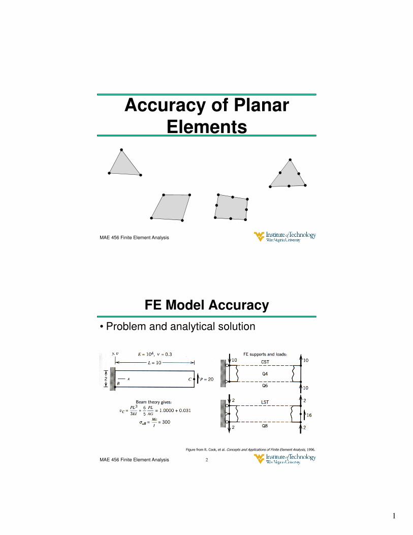
FE Model Accuracy
• Problem and analytical solution
2
Figure from R. Cook, et al. Concepts and Applications of Finite Element Analysis, 1996.
2
MAE 456 Finite Element Analysis
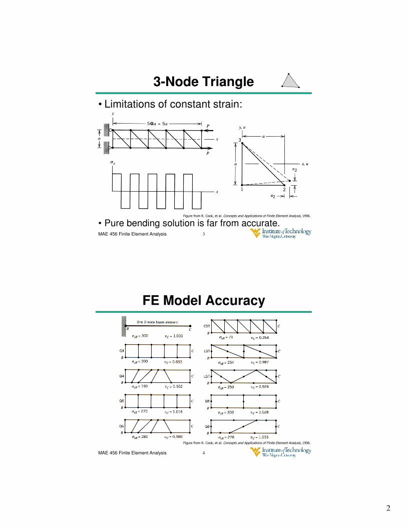
3-Node Triangle
3
• Pure bending solution is far from accurate.
• Limitations of constant strain:
Figure from R. Cook, et al. Concepts and Applications of Finite Element Analysis, 1996.
MAE 456 Finite Element Analysis
FE Model Accuracy
4
Figure from R. Cook, et al. Concepts and Applications of Finite Element Analysis, 1996.
3
MAE 456 Finite Element Analysis
Nature of the FE Approximation
Elasticity Theory tells us that a solution is
exact if:
1. The stress field obeys the equilibrium equations
2. Stress boundary conditions are met.
Fx and Fy are body forces per unit volume.
5
MAE 456 Finite Element Analysis
Nature of the FE Approximation
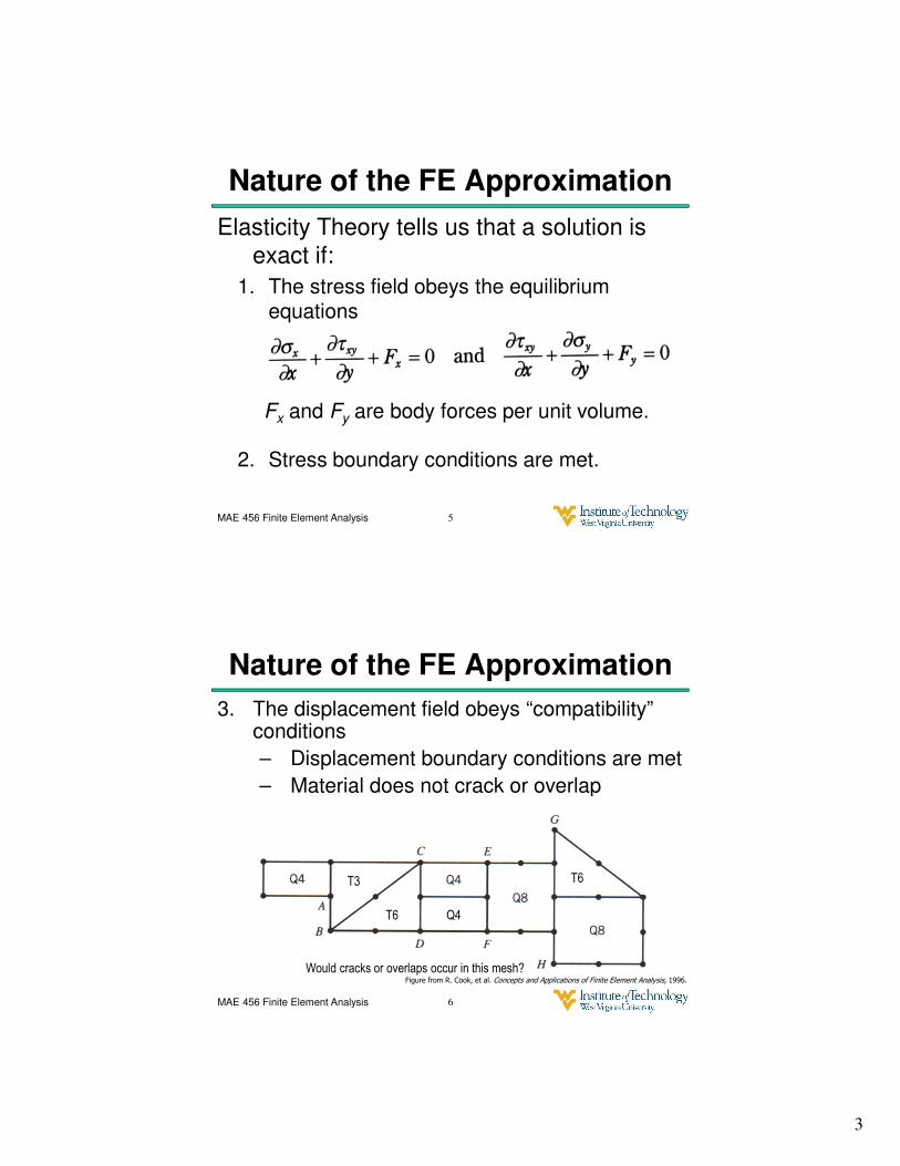
3. The displacement field obeys “compatibility” conditions
– Displacement boundary conditions are met
– Material does not crack or overlap
6
T3
T6 Q4
T6
Would cracks or overlaps occur in this mesh?Figure from R. Cook, et al. Concepts and Applications of Finite Element Analysis, 1996.
4
MAE 456 Finite Element Analysis
Nature of the FE Approximation
A Finite Element Model with elements
having polynomial shape functions will:
• Meet (3) the compatibility conditions
– Displacement BCs are met exactly at nodes
– Cracks/overlaps will not occur within elements
– Cracks/overlaps will not occur between elements with modern automated meshing
7
MAE 456 Finite Element Analysis
Nature of the FE Approximation
• Generally NOT meet Conditions (1) & (2)
– The stresses in adjacent elements will generally not match.
– The stresses in elements on the boundary will generally not match external pressures (represented by forces at nodes).
– However, these conditions are met in an average
sense. If you integrate the left side of the equilibrium equation,
the result will be zero for each element.
Refining the mesh size will improve the situation.
8
5
MAE 456 Finite Element Analysis
Nodal Averaging
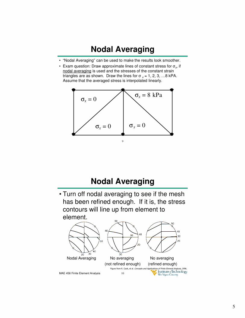
• “Nodal Averaging” can be used to make the results look smoother.
• Exam question: Draw approximate lines of constant stress for σx, if
nodal averaging is used and the stresses of the constant strain
triangles are as shown. Draw the lines for σ x = 1, 2, 3, …8 kPA.
Assume that the averaged stress is interpolated linearly.
σx = 0
σx = 0
σx = 8 kPa
σx = 0
9
MAE 456 Finite Element Analysis
Nodal Averaging
• Turn off nodal averaging to see if the mesh
has been refined enough. If it is, the stress
contours will line up from element to
element.
Nodal Averaging No averaging No averaging
(not refined enough) (refined enough)
10
Figure from R. Cook, et al. Concepts and Applications of Finite Element Analysis, 1996.
6
MAE 456 Finite Element Analysis 11
Gauss Quadrature
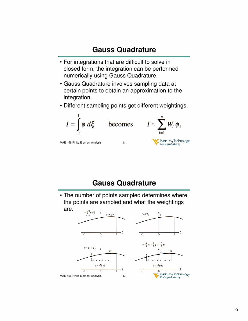
• For integrations that are difficult to solve in closed form, the integration can be performed numerically using Gauss Quadrature.
• Gauss Quadrature involves sampling data at certain points to obtain an approximation to the integration.
• Different sampling points get different weightings.
MAE 456 Finite Element Analysis 12
Gauss Quadrature
• The number of points sampled determines where the points are sampled and what the weightings are.
7
MAE 456 Finite Element Analysis 13
Gauss Quadrature
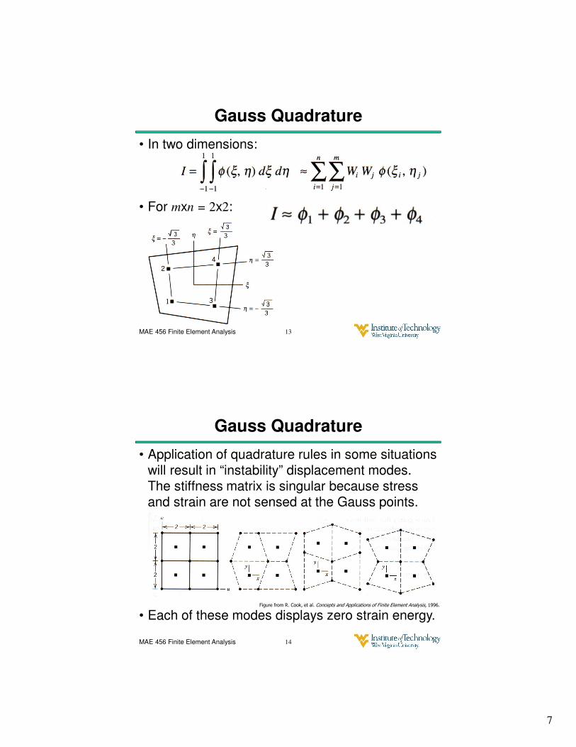
• In two dimensions:
• For mxn = 2x2:
MAE 456 Finite Element Analysis 14
Gauss Quadrature
• Application of quadrature rules in some situations will result in “instability” displacement modes. The stiffness matrix is singular because stress and strain are not sensed at the Gauss points.
• Each of these modes displays zero strain energy.Figure from R. Cook, et al. Concepts and Applications of Finite Element Analysis, 1996.


![Untitled 2 [] · /01-!." *23-!." 456-!." *+,-!7" /01-!7" *23-!7" 456-!7" *+,-#!" /01-#!" *23-#!" 456-#!" *+,-##" /01-##" *23-##" 456-##" *+,-#$" /01-#$" *23-#$" 456-#$" *+,-#%" /01](https://static.fdocuments.in/doc/165x107/5f2f2b6ad0823628e27434f2/untitled-2-01-23-456-7-01-7.jpg)