Accuracy and Realization Issues in Frequency Dependent...
7
Accuracy and Realization Issues in Frequency Dependent Sequence Networks Jo˜ ao P. L. Salvador, Felipe Camara Neto, Antonio C. S. Lima, Kai Strunz Abstract—With the more recent widespread of real-time simu- lation technologies, network equivalents received newly interest. Typically, the realization of a Frequency-Dependent Network Equivalent (FDNE) for electromagnetic transients (EMT) studies and its application on computational programs (EMTP) is based on a rational approximation of a given transfer function. One point that has not received much attention is to identify which aspects of the network being represented has a larger impact on the FDNE realization. In this paper we address some of these issues regarding the frequency dependency of overhead transmission lines parameters and the impact of actual transposition schemes on the realization network equivalents in sequence networks. Keywords: FDNE, Simulation Tools, EMTP, VF. I. I NTRODUCTION T YPICALLY power flow, harmonic penetration and tran- sient stability studies are carried out using positive se- quence networks considering a system with more than a few thousand busbars. Electromagnetic Transient (EMT) analysis on the other hand consider a different approach as the network modeling is more detailed, which demands a reduction on the actual size of the system to be represented. Although some recent efforts [1] tried to include a large portion of an actual network in EMTP-RV, the usual practice consists in deriving network equivalents to reduce the whole dimension of the system to be simulated. Furthermore, with the more recent widespread of real-time simulation technologies, there is a renew interest in improving the integration of the tools used to analyzed steady-state (load flow and harmonic penetration), electromechanical and electromagnetic transients. The main idea is to detail only a portion of the network in either a real-time simulation environment of EMT-type of program while the remainder of the network is represented using the conventional tools that rely on positive sequence networks modeling. The main reason why EMT studies are made in small parts of a given Power System is due to the relations between propagation functions and transmission line lengths. It is also important to note that the time range of the events considered are discrepant – less than a few miliseconds This work was made possible by a partial funding from INERGE, CNPq, CAPES and FAPEMIG. J.P.L. Salvador, F. Camara Neto and A.C.S. Lima are with Federal University of Rio de Janeiro, COPPE/UFRJ, Rio de Janeiro, RJ, Brazil (e-mails: [email protected], [email protected], [email protected]). K. Strunz is with Technical University of Berlin, Berlin, Germany (e-mail: kai.strunz@tu- berlin.de). Paper submitted to the International Conference on Power Systems Transients (IPST2015) in Cavtat, Croatia June 15-18, 2015. in EMT and more than a few seconds in angle stability or full steady-state in the case of harmonic penetration or load flow studies. Regardless of the procedure used to identify the rational approximation, one point remains of paramount importance: the impact of the accuracy of the network representation. If in one hand, the use of positive sequence is widely used in load flow and transient stability analysis, on the other hand, power system transients are usually evaluated in phase-coordinates and time-domain with different levels of approximation with respect to line modeling. Figure 1 presents a scheme that summarizes some possible interaction between power system simulation programs. Therefore, prior to the integration of the simulation tools, some investigations are required. In this paper we propose an approach where an Extra High Voltage AC transmission system is studied with different line models and transposition schemes. We obtain the rational approximations of frequency responses from the sequence networks of one terminal bus, i.e., a step before FDNE realization, and discuss its effects on the results. Simplified Network Large Dimensions Detailed Network Smaller Dimensions Load Flow Steady-state Fixed ω Positive Sequence Transient Stability Variable ω Positive Sequence Harmonic Studies Variable ω Positive Sequence EMTP Fig. 1. Simulation characteristics. The developments of an accurate representation of an equiv- alent reduced network, date back to 1970. The models then were implemented in a way of representing power system
Transcript of Accuracy and Realization Issues in Frequency Dependent...
Accuracy and Realization Issues in FrequencyDependent Sequence Networks
Joao P. L. Salvador, Felipe Camara Neto, Antonio C. S. Lima, Kai Strunz
Abstract—With the more recent widespread of real-time simu-lation technologies, network equivalents received newly interest.Typically, the realization of a Frequency-Dependent NetworkEquivalent (FDNE) for electromagnetic transients (EMT) studiesand its application on computational programs (EMTP) is basedon a rational approximation of a given transfer function. Onepoint that has not received much attention is to identify whichaspects of the network being represented has a larger impact onthe FDNE realization.
In this paper we address some of these issues regarding thefrequency dependency of overhead transmission lines parametersand the impact of actual transposition schemes on the realizationnetwork equivalents in sequence networks.
Keywords: FDNE, Simulation Tools, EMTP, VF.
I. INTRODUCTION
TYPICALLY power flow, harmonic penetration and tran-sient stability studies are carried out using positive se-
quence networks considering a system with more than a fewthousand busbars. Electromagnetic Transient (EMT) analysison the other hand consider a different approach as the networkmodeling is more detailed, which demands a reduction on theactual size of the system to be represented. Although somerecent efforts [1] tried to include a large portion of an actualnetwork in EMTP-RV, the usual practice consists in derivingnetwork equivalents to reduce the whole dimension of thesystem to be simulated. Furthermore, with the more recentwidespread of real-time simulation technologies, there is arenew interest in improving the integration of the tools usedto analyzed steady-state (load flow and harmonic penetration),electromechanical and electromagnetic transients.
The main idea is to detail only a portion of the networkin either a real-time simulation environment of EMT-type ofprogram while the remainder of the network is representedusing the conventional tools that rely on positive sequencenetworks modeling. The main reason why EMT studies aremade in small parts of a given Power System is due to therelations between propagation functions and transmission linelengths. It is also important to note that the time range of theevents considered are discrepant – less than a few miliseconds
This work was made possible by a partial funding from INERGE, CNPq,CAPES and FAPEMIG.J.P.L. Salvador, F. Camara Neto and A.C.S. Lima are with Federal Universityof Rio de Janeiro, COPPE/UFRJ, Rio de Janeiro, RJ, Brazil (e-mails:[email protected], [email protected], [email protected]). K. Strunz is withTechnical University of Berlin, Berlin, Germany (e-mail: [email protected]).Paper submitted to the International Conference on Power SystemsTransients (IPST2015) in Cavtat, Croatia June 15-18, 2015.
in EMT and more than a few seconds in angle stability or fullsteady-state in the case of harmonic penetration or load flowstudies.
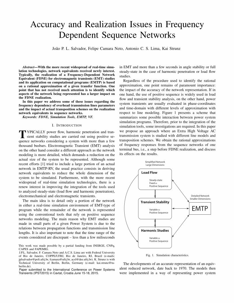
Regardless of the procedure used to identify the rationalapproximation, one point remains of paramount importance:the impact of the accuracy of the network representation. If inone hand, the use of positive sequence is widely used in loadflow and transient stability analysis, on the other hand, powersystem transients are usually evaluated in phase-coordinatesand time-domain with different levels of approximation withrespect to line modeling. Figure 1 presents a scheme thatsummarizes some possible interaction between power systemsimulation programs. Therefore, prior to the integration of thesimulation tools, some investigations are required. In this paperwe propose an approach where an Extra High Voltage ACtransmission system is studied with different line models andtransposition schemes. We obtain the rational approximationsof frequency responses from the sequence networks of oneterminal bus, i.e., a step before FDNE realization, and discussits effects on the results.
Simpli�ed NetworkLarge Dimensions
Detailed NetworkSmaller Dimensions
Load Flow
Steady-stateFixed ωPositive Sequence
Transient Stability
Variable ωPositive Sequence
Harmonic Studies
Variable ωPositive Sequence
EMTP
Fig. 1. Simulation characteristics.
The developments of an accurate representation of an equiv-alent reduced network, date back to 1970. The models thenwere implemented in a way of representing power system

behavior on Transient Network Analyzers (TNA) or on digitalcomputations. Computational tools were very limited at thattime so were some of the mathematical models involved.Consequently, very simple models were incorporated intothese types of analysis, specially regarding the representationof network equivalents.
Historically, the first publications aimed to synthesize fre-quency responses by the identification of resonance points [2]-[5]. In the following, series and/or parallel RLC branches wereset in order to match system behavior, only within a specificfrequency range. Some simplification assumptions, e.g., sym-metry, mainly in transmission lines, were adopted since itseffect should not affect significantly the evaluations. Anothercharacteristic from that time was that all network equiva-lents were single-port. Further developments enhanced fittingtechniques with new optimization features and extended themethods to multi-port equivalents [6], [7]. More recently, Gus-tavsen and Semlyen [8] proposed a robust frequency domainrational fitting technique based on a pole relocation scheme,the so-called Vector Fitting algorithm (VF). This method is areformulation of Sanathanan-Koerner (SK) [11] iteration usingpartial fractions basis, which later received improvements [12],[13]. Due its accuracy, its ready-to-use feature and the factthat it is available as a public domain Matlab routine, thistechnique became widely used. Nevertheless, there are otherapproaches applied for electromagnetic transient studies. Onemay approach the problem of rational fitting as an optimizationproblem using a Levenberg-Marquardt algorithm [14]–[16].The actual poles of a given system may be identified usingDominant Poles and Multiple Dominant Poles Methods [17]-[19]. After the identification of poles, residues can be easilyidentified. Another approach that is drawing more attentionnowadays is the use of the Matrix Pencil Method [20], [21].
II. SYSTEM MODELING
The main objective of this paper is to provide an analysisregarding the importance of frequency dependency inclusionand transposition schemes in actual power systems involvingoverhead transmission lines (OHL). The system used for thetest is shown in Fig. 2. It contains two generation equivalentsin buses #1 (500 kV) and #12 (230 kV); four 500 kV and nine230 kV overhead transmission lines, with lengths from 19 upto 240 km; shunt reactive compensation in buses #2 and #3;and a capacitor bank in bus #4. The loads are connected tovoltage levels below 230 kV, except the load on bus #4, whichrepresents a static compensator. The network configurationis based on a part of the actual Extra High Voltage Systemexisting in the North of Brazil. Figures 3(a) and 3(b) show theline profile for the 230 kV and 500 kV circuits.
Typically, for the harmonic penetration analysis of thesystem in Fig. 2, all OHL would assume ideal transpositionand constant parameter line model would be used. However,in fact only the longer circuits (with lengths over 100 km)should be transposed. Furthermore, an actual, instead of ideal,transposition is used. In this work we aim to investigate theimpact that this simplification might affect the realization
of a frequency dependent network equivalent (FDNE) in thesequence domain.
(a) 230 kV tower. (b) 500 kV tower.
Fig. 3. Profiles for overhead lines.
A. Overhead Transmission Lines
The Bergeron overhead transmission line model is a rep-resentation of the traveling wave model, with distributedparameters. It was first introduced on EMTP by Dommel [22].It also is known as the constant parameter line model. Lossesare included by lumped resistances [23] at line ends, seeFig. 4(a). Alternatively, one may use the modal domainfrequency dependent line model proposed by Marti [24], alsoknown as JMarti model. It consists on an accurate modelfor the inclusion of frequency dependency of parameters inelectromagnetic transient time-domain simulation as long asthe transformation matrix is assumed real and constant. Themodel is based on a polynomial fitting in the frequency domainof the characteristic impedance ZC(ω), ZEQ and the usageof a Thevenin equivalent as depicted in Fig. 4(b), whereBi and Fi are backward and forward waves, and Hc is thewave propagation function.
vm(t)ZC
Ik(t-τ)
ZC
R/2
Im(t-τ)
R/2ikm(t) imk(t)
vk(t)
(a) Bergeron (lossy constant parameter)
vm(t)
ikm(t) imk(t)
vk(t)
ZEQ = ZC(ω) ZEQ = ZC(ω)
Bm = HC(ω)Fm(ω) Bk = HC(ω)Fk(ω)
(b) JMarti (frequency dependent)
Fig. 4. Basic structure of line models.

#1 #2 #3 #4 #5
#6
#7#8
#9
#10
#11#12
195 km
195 km
107 km
107 km
19 km
19 km
36 km
95 km95 km120 km
223 km
129 km 240 km
Fig. 2. System under study.
B. TranspositionIn an actual transmission line, both impedance and admit-
tance matrices per unit length are symmetrical but not bal-anced [25]. For instance, the impedance presents the followingstructure
Z =
ZSA ZmAB ZmAC
ZmAB ZSB ZmBC
ZmAC ZmBC ZSC
(1)
where ZSi is the self-impedance of phase i and Zmij themutual impedances between phases i and j. In the case of anideally transposed line, i.e., if there are infinitesimal rotationbetween phase conductors, the impedance can be written as
Zapprox =
ZS Zm Zm
Zm ZS Zm
Zm Zm ZS
(2)
In actual transmission circuits the structure shown in (2) isapproximately obtained by a discrete transposition scheme.The circuit is divided in four parts with the transpositiontaking place at 1/6, 1/3, 2/3 and 5/6 of the total line length.The discrete transposition scheme creates a small unbalancewhich might be of importance, specially if harmonic studiesare involved.
C. Rational ApproximationThe so-called Vector Fitting Algorithm (VF) has become
one of the most applied techniques for the FDNE realization.Consider a discrete frequency function f(s), it is possible towrite an approximation in terms os a ratio of two polynomialfunctions [10]:
f(s) ≈ an sn + an−1 s
n−1 + · · ·+ a0bm sm + bm−1 sm−1 + · · ·+ b0
(3)
In order to avoid polynomial division, (3) may be rewritten asa sum of partial fractions, i.e., a rational approximation:
f(s) ≈N∑
n=1
rns− pn
+ d+ se (4)
where N is the order of approximation, rn are the residues,pn the poles, d is the independent term and e is the termproportional to s. VF identifies the poles of f(s) by solving(5) as a linear least squares problem
σ(s)f(s) =N∑
n=1
rns−pn
+ d+ se
σ(s) =N∑
n=1
rns−pn
+ 1
(5)
where pn are the chosen initial poles. It can be shown [10]that the poles of f(s) are equal to the zeros of σ(s) which arecalculated as the eigenvalues of the matrix
pn = eig(A− bcT) (6)
where A is a diagonal matrix containing the initial poles pn,b is a row vector of ones and cT is a column vector with theresidues rn. The procedure runs always with a known set ofpoles, since the new poles pn take the place of the old onespn in the following iteration. Once the poles are identified, theresidues are calculated by solving (5).
The advantage of VF usage lies with its capability ofapproximating the given function with no knowledge of thesystem itself, i.e., only approximating the frequency response,which speeds computation. Although the calculated poles maynot be the actual system poles, it is not always possibleto know all of them, hence, the approximation may be theonly way to describe the system under study. In this paper,we assumed that there are not coupling between sequencenetworks then only single-phase impedances or admittancesare involved and there is no need to enforce passivity as inthe case of rational approximation of admittance matrices [27],[28].
III. SIMULATION RESULTS
The rational approximation in terms of Eq. (4) parameterslead to the conclusion that variable e may be interpreted as acapacitance, if f(s) is the admittance of the measured bus [29].

(a) Bergeron. (b) JMarti.
Fig. 5. Y1 assuming all lines ideally transposed.
(a) Bergeron. (b) JMarti.
Fig. 6. Y0 assuming all lines ideally transposed.
(a) Bergeron. (b) JMarti.
Fig. 7. Y1 with untransposed (shorter) lines, longer lines ideally transposed.
Therefore, in this paper we will apply this information toconsider e = 0 and apply VF algorithm to obtain a FDNE fromthe admittance response of bus #4. It should be highlighted thattransmission lines directly connected to bus #4 have less than100 km. To obtain the frequency response of bus #4, we usedthe Frequency Scan from ATP. In appendix A we review thebasic procedure to obtain the sequence domain impedances.
The frequency responses and VF approximation of positive-and zero-sequence admittance simulated at bus #4 are shownin this Section. To determine the order of approximation, we
have chosen the lowest number of poles that produced an RMSerror below 10−2, based on the absolute minimum value ofeach curve.
Frequency responses obtained with the transmission systemmodeled by Bergeron have a noticeable oscillatory behavior,with peaks way higher than with JMarti model, for higherfrequencies. For positive-sequence and, specially, for zero-sequence responses, the attenuation of admittance magnitudewas significant.
Based on several evaluations on impedance and admittance

(a) Bergeron. (b) JMarti.
Fig. 8. Y0 with untransposed (shorter) lines, longer lines ideally transposed.
(a) Bergeron. (b) JMarti.
Fig. 9. Y1 using actual transposition scheme for longer lines, shorter lines untransposed.
(a) Bergeron. (b) JMarti.
Fig. 10. Y0 using transposition scheme for longer lines, shorter lines untransposed.
fitting [30], results showed that since admittance frequencyresponses presented more attenuate tendencies, they becomemore suitable for rational fitting than the impedance frequencyresponses.
For the ideally transposed transmission system, Figs. 5(a)and (b) depict the positive-sequence admittance calculated foreach line model and Figs. 6(a) and (b), the zero-sequence.For the entire frequency range, it is possible to notice theattenuation of the admittance behavior, considering JMartimodel, especially for zero-sequence response.
Considering the untransposed transmission system,Figs. 7(a) and (b) depict the positive-sequence and Figs. 8(a)and (b), the zero-sequence responses. We were unable toachieve the criterion of RMS error for positive-sequenceresponses, even though were they quite similar to those ofFigs. 5(a) and (b). Zero-sequence responses kept its behavior.
Finally, the influence of an actual transposition scheme ap-plied to the transmission system can be evaluated in Figs. 9(a)and (b) for the positive-sequence and in Figs. 10(a) and (b)for zero-sequence. Tab. I summarizes the results of the rational

approximation using VF, including the number of poles andRMS error calculated for each case.
TABLE IRESULTS OF VF.
Sequence OHL Transp. Number of RMS-Admittance Model Scheme Poles Err
Ideal 208 8.152× 10⁻³
Bergeron Un 424 2.219× 10⁻²
Positive Actual 256 8.456× 10⁻³
Y1 Ideal 282 6.659× 10⁻³
JMarti Un 418 2.490× 10⁻²
Actual 150 6.271× 10⁻³
Ideal 292 9.840× 10⁻³
Bergeron Un 284 7.866× 10⁻³
Zero Actual 350 9.676× 10⁻³
Y0 Ideal 78 8.816× 10⁻³
JMarti Un 60 9.839× 10⁻³
Actual 52 9.833× 10⁻³
IV. CONCLUSIONS
This work has focused on the rational approximations ofnetwork equivalents using sequence domain. It was foundthat regardless of the inclusion of frequency dependencyand transposition scheme, an accurate representation of thesystem’s frequency response was obtained using the VectorFitting technique. The inclusion of the frequency dependencywas of paramount importance for a lower order realization.The usage of conventional line models such as the Bergeronmodel implied in a significant increase in the number of thepoles to achieve a precise fitting function.
The evaluation of the RMS error for the fitted admit-tance presented a smoother behavior when compared withfitted impedance. The inclusion of the transposition schemeproduced a noticeable impact in the behavior of both theequivalent impedance and the admittance in the higher fre-quencies. This did impact the quality of the rational model. It isimportant to mention that more accurate representation of thenetwork provided functions that were more easily fitted, i.e.,considering a frequency dependent line model with an actualtransposition scheme provided equivalents that were moreeasily fitted using a rational model. This result emphasizesthat a system that has a modeling closer to its actual behaviorcan be approximated with rational functions.
V. ACKNOWLEDGMENT
The authors would like to thank Dr. Alecio Fernandes fromthe Brazilian National System Operator (ONS) for usefuldiscussions on the subject.
REFERENCES
[1] L. Grin-Lajoie, J. Mahseredjian, “Simulation of an Extra Large Networkin EMTP: from Electromagnetic to Electromechanical Transients,” In:IPST’09 – International Conference on Power System Transients, Kyoto,Japan, 2009.
[2] N. Hingorani, M. Burbery, “Simulation of AC System Impedance inHVDC System Studies,” IEEE Trans. on Power Apparatus and Systems,v. PAS-89, n. 5, May 1970.
[3] A. Clerici, L. Marzio, “Coordinated Use of TNA and Digital Computerfor Switching Surge Studies: Transient of a Complex Network,” IEEETrans. on Power Apparatus and Systems, v. PAS-89, n. 8, November1970.
[4] A. Morched, V. Brandwajn, “Transmission Network Equivalents forElectromagnetic Transients Studies,” IEEE Trans. on Power Apparatusand Systems, v. PAS-102, n. 9, September 1983.
[5] V. Do, M. Gavrilovic, “An Iterative Pole-Removal Method for Syn-thesis of Power System Equivalent Networks,” IEEE Trans. on PowerApparatus and Systems, v. PAS-103, n. 8, August 1984.
[6] V. Do, M. Gavrilovic, “A Synthesis Method for One-Port and Multi-PortEquivalent Networks for Analysis of Power System Transients,” IEEETrans. on Power Delivery, v. 01, n. 02, April 1986.
[7] A. Morched, J. Ottevangers, L. Mart, “Multi-Port Frequency DependentNetwork Equivalents for the EMTP,” IEEE Trans. on Power Delivery,v. 08, n. 03, July 1993.
[8] B. Gustavsen, A. Semlyen, “Simulation of Transmission Line transientsUsing Vector Fitting and Modal Decomposition,” IEEE Trans. on PowerDelivery, vol. 13, n. 02, April 1998.
[9] B. Gustavsen, A. Semlyen, “Combined Phase and Modal DomainCalculation of Transmission Line Transients Based on Vector Vitting,”IEEE Trans. on Power Delivery, vol. 13, n. 02, April 1998.
[10] B. Gustavsen, A. Semlyen, “Rational Approximation of FrequencyDomain Responses by Vector Fitting,” IEEE Trans. on Power Delivery,vol. 13, n. 04, 1999.
[11] C.K. Sanathanan, J. Koerner, “Transfer function synthesis as a ratio oftwo complex polynomials,” IEEE Trans. Automatic Control, vol. 8, no.1, pp. 56-58, Jan. 1963.
[12] B. Gustavsen, “Improving the pole relocating properties of vectorfitting,” IEEE Trans. on Power Delivery, vol. 21, no. 03, pp. 1587-1592,July 2006.
[13] D. Deschrijver, M. Mrozowski, T. Dhaene, D. De Zutter, “Macromod-eling of Multiport Systems Using a Fast Implementation of the VectorFitting Method,” IEEE Microwave and Wireless Components Letters,vol. 18, no. 6, pp. 383-385, June 2008.
[14] A. B. Fernandes, Transmission Lines: Optimized Model for Electromag-netic Transient Studies, M.Sc. Thesis (in Portuguese), Federal Universityof Paraıba, Brazil, 1996.
[15] A. B. Fernandes, W. L. A. Neves, “Transmission Lines: FittingTechnique Optimization,” In: IPST’97 – International Conference onPower Systems Transients, Seattle, 1997.
[16] A. B. Fernandes, W. L. A. Neves, “Frequency-Dependent Transforma-tion Matrices for Phase-Domain Transmission Line Models,” IEEE PESSummer Meeting, v. 3, pp. 1782-1787, 2001.
[17] N. Martins, L. T. G. Lima, H. J. C. P. Pinto, “Computing Dominant Polesof Power System Transfer Functions,” IEEE Trans. on Power Systems,v. 11, n. 1, pp. 162-170, 1996.
[18] N. Martins, P. E. M. Quintao, “Computing Dominant Poles of PowerSystem Multivariable Transfer Functions,” IEEE Trans. on Power Sys-tems, v. 18, n. 1, pp. 152-159, 2003.
[19] S. Gomes Jr., N. Martins, S. L. Varricchio, et al., “Modal Analysis ofElectromagnetic Transients in ac Network Having Long TransmissionLines,” IEEE Trans. on Power Delivery, v. 20, n. 4, pp. 2623-2630,2005.
[20] K. Sheshyekani, H. R. Karami, P. Dehkhoda, et al., “A New Method forthe Inclusion of Frequency Domain Responses in Time Domain Codes,”In: IPST’11 – International Conference on Power Systems Transients,Delft, 2011.
[21] K. Sheshyekani, H. R. Karami, P. Dehkhoda, et al., “Application ofthe Matrix Pencil Method to Rational Fitting of Frequency-DomainResponses,” IEEE Trans. on Power Delivery, v. 27, n. 4, pp. 2399-2408,2012.
[22] H. W. Dommel, “Digital Computer Solution of Electromagnetic Tran-sients in Single- and Multiphase Networks,” IEEE Trans. on PowerApparatus and Systems, v. PAS-88, n. 4, pp. 388-399, 1969.
[23] N. Watson, J. Arrillaga, Power Systems Electromagnetic TransientsSimulation, N. 39, IEE Power and Energy Series, 2007.
[24] J. R. Marti, “Accurate Modeling of Frequency-Dependent TransmissionLines in Electromagnetic Transient Simulations,” IEEE Trans. on PowerApparatus and Systems, v. PAS-101, n. 1, pp. 147-155, 1982.

[25] P. M. Anderson, Analysis of Faulted Power Systems, IEEE Press – PowerSystems Engineering Series, 1995.
[26] J. Arrillaga, E. Acha, T. J. Densem, P. S. Bodger, “Ineffectivenessof Transmission Line Transpositions at Harmonic Frequencies,” IEEProceedings, vol. 133, n. 2, 1986.
[27] B. Gustavsen, The Vector Fitting Web Site. Available:<http://www.sintef.no/Projectweb/VECTFIT/>, 1998.
[28] B. Gustavsen, A. Semlyen, “Enforcing Passivity for Admittance Ma-trices Approximated by Rational Functions,”, IEEE Trans. on PowerSystems, v. 16, n. 1, pp. 97-104, 2001.
[29] B. Gustavsen, “Computer Code for Rational Approximation of Fre-quency Dependent Admittance Matrices,” IEEE Trans. on Power De-livery, vol. 17, pp. 1093-1098, 2002.
[30] J. P. L. Salvador, “A Study of Frequency Dependent Network Equiva-lents,” M.Sc. Dissertation (in Portuguese), Federal University of Rio deJaneiro, COPPE/UFRJ, Rio de Janeiro, Brazil, 2014.
APPENDIX
A. Sequence NetworksThe procedure is based on calculating the Thevenin equiv-
alent impedance from the terminal of interest. By injecting athree-phase current source with magnitude 1.0 A and phaseangles shown in Tab. II, we establish a simplification wherethe only measured quantity is the voltage in phase A. Whenconsidering an ideally transposed transmission system, thesymmetric current source provokes symmetric voltage mea-surements, which gives a unique sequence network response.Hence, we may account, e.g., that the positive-sequenceimpedance is the ratio of the voltage measured over phase Awith respect to the current applied on phase A, i.e., 1.0 A, forthey are equal do the positive-sequence voltage and current,respectively. Equation (7) show this evaluation, also valid fornegative- and zero-sequence networks.
TABLE IIANGLES OF THE THREE-PHASE SOURCE.
Sequence θA θB θCZero 0◦ 0◦ 0◦
Positive 0◦ −120◦ +120◦
Negative 0◦ +120◦ −120◦
VAVB = α2VAVC = αVA
=⇒
V0 = 0V1 = VAV2 = 0
IA = 1∠0◦
IB = 1∠− 120◦
IC = 1∠+ 120◦
=⇒
I0 = 0I1 = IAI2 = 0
0VA0
=
Z0 0 00 Z1 00 0 Z2
01∠0◦
0
=⇒ Z1 =
VA1.0∠0◦
∴ Z1 = VA �
(7)
However, in the cases where the transmission system is notideally transposed, there exists mutual components betweenpositive- and zero-sequence networks. For the results we showin this paper, we bypass the mutual relations of sequencesand only consider Y1 = I1/V1 and Y0 = I0/V0 as sequencenetworks, due to the little influence these mutual componentsimpose over the responses.
As it consists on a single curve, the sequence admittancefrequency responses can be found simply by calculatingYseq(sk) = 1/Zseq(sk) for each point of frequency sk. Forthe power system we consider in this paper, we use admittanceinstead of impedance. In this paper, the generators are mod-eled as three-phase voltage sources behind impedances, thusnegative-sequence behavior is identical to the one presentedby positive-sequence.