AccuFlo HMP - ski-gmbh.com
12
AccuFlo ® HMP
Transcript of AccuFlo HMP - ski-gmbh.com
AccuFlo®HMP

2
Our highlights
• “Plug and Play“- system
• Maximum error of 0.3% of measured value
• Almost no straight inlet and outlet sections required
• Dynamic Measuring Ratio of 1:15
• Low pressure drop
• Maintenance-free if AccuFlo®-Zero option is used
• Fiscal measurement for steam, gas and liquids
• Various fi eld bus interfaces available
• Next generation fl ow computer with touchscreen display
and state of the art calculation algorithms
Highlights

3
AccuFlo® HMP G – Highly accurate fiscal measurement for gas
Due to the ever increasing energy prices exact
flow measurement of gas is becoming increasin-
gly important. This applies to natural gas but also
to compressed air and industrial gases. Especially
at larger diameters where more energy is trans-
ported the AccuFlo® HMP G offers an optimal so-
lution with a diameter range from DN40 to DN300
and a margin of error of up to 0.3% coupled with
an excellent price-performance ratio.
An example of the numerous areas of applica-
tion is the measurement of natural gas as a ma-
jor energy source. In addition to official custody
transfer measurements numerous operational
measurements are of particular importance
here. Price measurement of gas flow is one a
prerequisite for an efficient combustion process.
The AccuFlo® HMP G provides an economically
attractive solution, even under the toughest con-
ditions such as strong vibrations of the pipe and
high ambient temperatures. The AccuFlo® HMP G
is easy to use even in extremely compact instal-
lations. It combines very short installation length
with minimal to no additional straight inlet and
outlet sections in order to meet the specified
accuracy.
The measurement system can also be equipped
for completely maintenance free operation.
Changes in ambient and operating conditions
usually require regular zero point calibrations, all
of which are performed automatically in combi-
nation with the AccuFlo®-Zero option.
Due to its optionally variable length, the installa-
tion is possible without welding works by simple
replacing the existing measurement system.
Application: fiscal gas measurement

4
AccuFlo® HMP ST – Highly accurate fi scal measurement for steam
In the steam sector, the AccuFlo® HMP ST offers
the possibility to measure mass and energy fl ow
of steam accurately and traceably. Discussions
about precision are a thing of the past.
Since the calibration of measurements with
steam is almost impossible, it was normal in the
past to use measuring devices that are not tra-
ceable to calibration standards for the fi scal
metering of steam fl ow. This is very different with
the AccuFlo® HMP ST. Due to the measuring prin-
ciple the results of the water calibration can be
transferred to steam measurements without limi-
tations. This ensures a high accuracy and 100%
traceable steam measurement for the end user.
The AccuFlo® HMP ST can even be used in very
compact pipe networks due its short installation
length and furthermore it requires no additional
straight in- and outlet sections to achieve the
specifi ed accuracy.
The measurement system can also be equipped
for completely maintenance free operation.
Changes in ambient and operating conditions
usually require regular zero point calibrations, all
of which are performed automatically in combi-
nation with the AccuFlo® -Zero option.
The mass fl ow meter is easy to install and due its
variable length it offers great fl exibility when it
comes to upgrading facilities or replacing exis-
ting fl ow meters.
Application: fi scal steam measurement

5
AccuFlo® HMP L – highly accurateaccounting measurement forspecial fl uids
In the fi eld of fl ow measurement of liquids vari-
ous fl ow measurement methods are availab-
le. In particular for conductive water the list of
available devices is very long. For specifi c requi-
rements for the measurement of low-viscosity or
non-conductive liquids at high temperature and
high pressure this list is much shorter. The search
is getting more diffi cult if these specifi cations are
combined with the requirement of very high ac-
curacy. In these cases the AccuFlo® HMP L is the
fi rst choice.
The measurement of a fl ow of thermal oil or sup-
ply water at 300 ° C with an error margin of up
to 0.3% of the measured value in a span ratio of
1:15 are typical applications here. Also regarding
the process pressure, there are no restrictions for
pressures up to PN160.
The AccuFlo® HMP L can even be used in very
compact pipe networks due its short installation
length and furthermore it requires no additional
straight in- and outlet sections to achieve the
specifi ed accuracy.
The measurement system can also be equipped
for completely maintenance free operation.
Changes in ambient and operating conditions
usually require regular zero point calibrations, all
of which are performed automatically in combi-
nation with the AccuFlo®-Zero option.
The mass fl ow meter is easy to install and due its
variable length it offers great fl exibility when it co-
mes to upgrading facilities or replacing existing
fl ow meters.
Application: fi scal liquid measurement

6
The AccuFlo® HMP ST is a high accuracy differen-
tial pressure mass flow meter. The special design
of the measuring sensors results in a combinati-
on of high accuracy with low-pressure drop and
cost-efficiency in an optimal way.
The overall maximum measurement error under
reference conditions is +/- 0.3% of the measured
value for liquid and gaseous media and 0.5% of
the measured value for steam. When using the
AccuFlo®-Zero option the error limits are usually
met even taking into account the usual factors
such as changes in fluid and ambient tempera-
ture, media pressure and the long-term drift of
the electronic differential pressure transmitter.
The diagram below shows a typical calibration
curve for water. Due to f the physical relations
these results can be applied without restrictions
to compressible media if the expansion factor is
taken into account. The AccuMind serves as flow
computing unit of the AccuFlo® HMP and per-
forms all necessary calculations to achieve the
highest accuracy.
The graphic below demonstrates the indepen-
dence of the measurement result of inlet and
outlet section. The AccuFlo® HMP can be opera-
ted largely without inlet and outlet sections and is
therefore suitable for fiscal metering applications
in complex piping systems and in extremely com-
pact installations.
The use of the AccuFlo® -Zero option offers com-
plete freedom from maintenance in addition to
increased accuracy. Changes in ambient and
operating conditions usually require regular zero
point calibrations, all of which are performed
automatically in combination with the AccuFlo®-
Zero option.
AccuFlo® HMP – Principle of operation
0.30%
0.20%
0.10%
0.00%
-0.10%
-0.20%
-0.30%
0 50 100 150 200 250 300t/h
Measurement error (of actual value)

7
Intelligent Sensor Alignement
The combination of flow conditioning and fine-
meshed sampling of the flow profile provides a
stable measuring signal that is largely indepen-
dent of inlet disturbance over a wide measuring
range. The flow-optimized design ensures low-
pressure losses resulting usually in a static pressure
drop smaller than 21% of the generated differen-
tial pressure.
Your benefits:
• Very high accuracy
• Large dynamic measurement range
• Compact design of your installation,
since no straight inlet and outlet sections
are necessary
• Low operating costs due to low pressure
losses
Digital Communication betweenDifferential Pressure Transmitter and Flow Computer
In most differential pressure flow measurements
the communication between the differential
pressure transmitter and the flow computer elec-
tronics are based on analog signals. Due to the
quadratic relationship between flow and dif-
ferential pressure this results in severely limited
accuracy at low flow. Digital communication
(e.g.via PROFIBUS) requires special differential
pressure transmitters and processing electronics
which lead to a significant increase in cost. This is
different with the AccuFlo® HMP where commu-
nication between transmitter and flow computer
is purely digital – without additional cost for the
end-user.
Your benefits:
• High accuracy (measurement error of
0.3% of measured value for gas, 0.5% for
steam) Due to digital communication
there are virtually no extra costs
• Large dynamic measurement range
(typically 1:15) without additional device-
and installation effort
Our Innovation - Your Benefit

8
Next Generation Flow Computer
The fl ow computer can be operated intuitively
via the freely confi gurable capacitive touch-
screen display. For accurate mass fl ow metering
it features all relevant international regulations
such as calculation AGA8 DC92 (Detailed Me-
thod), ISO20765, SGERG-88, AGA-NX19 and IAP-
WS97. Integration into almost all available bus
systems such as Modbus, Profi bus and Profi net is
possible due to the AnyBus-module.
Your benefi ts:
• Highly accurate measurement of natural
gas according to virtually all applicable
standards
• Can be integrated in virtually all Fieldbus
systems
• Steam fl ow measurement according to
current standards
Optional Automatic Zero PointCalibration
Zero calibration is performed as required depen-
ding on ambient temperature and / or media
pressure fl uctuations. In addition, a zero point
calibration is performed to avoid measurement
errors due to the long-term drift of the differential
pressure transmitter.
Your benefi ts:
• High accuracy under realistic process
conditions
• Maintenance free
• Accurate measurement even at low fl ow
due to the extended dynamic measure-
ment range
Our innovation - your benefi ts

9
Liquid gas flow measurement
Steam measurement horizontal
Steam measurement vertical
Dimensions and weights
Nominal widthDN 80
DN 100
DN 125
DN 150
DN 200
DN 250
DN 300
* Total Length L can be differ according to the customer’s wishes
Length L* (mm)500
500
500
500
600
700
800
Height H(ca. mm)
435
450
460
475
500
530
555
Nominal widtheDN 80
DN 100
DN 125
DN 150
DN 200
DN 250
DN 300
Nominal widtheDN 80
DN 100
DN 125
DN 150
DN 200
DN 250
DN 300
* Total Length L can be different according to what the customer wants
* Total Length H3 can differ according to the customer’s wishes
Length L* (mm)500
500
500
500
600
700
800
Length H3 (mm)500
500
500
500
600
700
800
Height H1
(ca. mm)325
340
340
365
390
420
445
Height H4(ca. mm)
80
80
80
80
25
-
-
Height H2
(ca. mm)255
265
280
295
320
345
370
Depth1 T2(ca. mm)
375
385
400
415
440
465
490
Depth T1(ca. mm)
375
385
400
415
440
465
490
Depth2 T3(ca. mm)
195
210
220
235
260
290
315
Weights of gas- and liquid measurements (Standard Length)
Weight steam measurement (Standard Length)
DN
80
100
125
150
200
250
300
DN
80
100
125
150
200
250
300
PN6
30
36
46
58
92
144
213
PN6
33
39
49
61
95
147
216
PN10
32
38
48
63
97
150
217
PN10
35
41
51
66
100
153
220
PN16
32
38
48
63
98
154
227
PN16
35
41
51
66
101
157
230
PN63
37
46
61
84
140
212
311
PN63
40
49
64
87
143
215
314
PN40
33
42
53
70
114
185
280
PN40
36
45
56
73
117
188
283
PN100
41
52
73
98
166
267
403
PN100
44
55
76
101
169
270
406
Weight G(ca. kg)
See table as it
depends on the
pressure stage
10
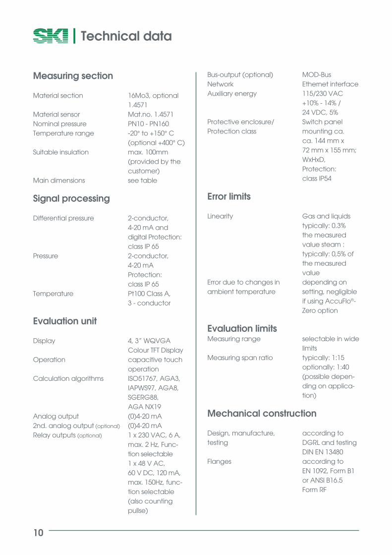
Measuring section
Material section 16Mo3, optional 1.4571Material sensor Mat.no. 1.4571Nominal pressure PN10 - PN160Temperature range -20° to +150° C (optional +400° C)Suitable insulation max. 100mm (provided by the customer)Main dimensions see table
Signal processing
Differential pressure 2-conductor, 4-20 mA and digital Protection: class IP 65Pressure 2-conductor, 4-20 mA Protection: class IP 65Temperature Pt100 Class A, 3 - conductor
Evaluation unit
Display 4, 3” WQVGA Colour TFT DisplayOperation capacitive touch operationCalculation algorithms ISO51767, AGA3, IAPWS97, AGA8, SGERG88, AGA NX19Analog output (0)4-20 mA2nd. analog output (optional) (0)4-20 mARelay outputs (optional) 1 x 230 VAC, 6 A, max. 2 Hz, Func- tion selectable 1 x 48 V AC, 60 V DC, 120 mA, max. 150Hz, func- tion selectable (also counting pullse)
Bus-output (optional) MOD-BusNetwork Ethernet interfaceAuxiliary energy 115/230 VAC +10% - 14% / 24 VDC, 5%Protective enclosure/ Switch panelProtection class mounting ca. ca. 144 mm x 72 mm x 155 mm; WxHxD, Protection: class IP54
Error limits
Linearity Gas and liquids typically: 0.3% the measured value steam : typically: 0,5% of the measured value Error due to changes in depending on ambient temperature setting, negligible if using AccuFlo®- Zero option
Evaluation limitsMeasuring range selectable in wide limitsMeasuring span ratio typically: 1:15 optionally: 1:40 (possible depen- ding on applica- tion)
Mechanical construction
Design, manufacture, according totesting DGRL and testing DIN EN 13480 Flanges according to EN 1092, Form B1 or ANSI B16.5 Form RF
Technical data

11
AccuFlo® HMP
Ordering Codes
40506580100125150200250300
10164063100160
GSTL
Nominal width (EN 1092, ANSI B16.5)
Type of medium
Pressure stage (EN 1092, ANSI B16.5)
DN40 / 1“ DN50 / 2“ DN65 / 2“ DN80 / 3“ DN100 / 4“ DN125 / 5“DN150 / 6“ DN200 / 8“ DN250 / 10“ DN300 / 12“
GasSteamLiquid
10164063100160
DC ACDEAE
HVSVF
A2R2MEEX
24AZX
Version
Pipeline layout – flow direction
Pipeline layout - flow direction
PN10 (available from DN250/10“)PN16 /class#150 (available from DN100/4“)PN40 /class#300PN63 /class#400PN100 /class#600PN160 /class#900
nach EN 1092, 16 Mo3nach ANSI B16.5, 16Mo3nach EN 1092, stainless steelnach ANSI B16.5, stainless steel
HorizontalVertical - risingVertikal - falling
Second analog outputTwo relay outputsmeasuring range extension (1:40)EX-version with feed separator(correction calculator without EX)24 V DC - VersionAccuFlo® ZeroFurther option – plain text input successful

12
S.K.I. Schlegel & KremerIndustrieautomation GmbHP.O. Box 41 01 31
D-41241 Mönchengladbach
Hanns-Martin-Schleyer-Straße 22
D-41199 Mönchengladbach
Phone: +49(0)2166-62317-0
Fax: +49(0)2166-62317-99
Web: www.ski-gmbh.com
Email: [email protected]
VAT Reg. No. De 811 352 712
Mönchengladbach Distrtict Court Companies Register HRB 4470
PR-AccuFlo HMP-en-1705