
AccuFIT 9000 - Accutec-IHS | Accuracy = Safety
39
Operation Manual Users are cautioned to read this manual carefully and understand the warnings described in this manual before operating the product. Please keep this manual handy for future reference. AccuTec-IHS AccuFIT 9000 01 002RC5 18.08
Transcript of AccuFIT 9000 - Accutec-IHS | Accuracy = Safety

Operation Manual
Users are cautioned to read this manual carefully and understand the warnings
described in this manual before operating the product.
Please keep this manual handy for future reference.
AccuTec-IHS
AccuFIT 9000
01 002RC5
18.08

Component List
■ Standard
ITEM MODEL QTY
Main Unit 1
AC Adapter(100-240V、12V 2A) AF90-ADP
1
Power Cord 1
Zero Filter 2
Alcohol Storage Container AF90-AFC 1
Storage Cap AF90-CAP 1
Alcohol Cartridge AF90-ACR 1
Spare Felt/Wire Mesh AF90-AWK 2
Software CD 1
Twin Tube (1m) 1
Carrying Case 1
■ Consumables
ITEM MODEL QTY
Zero Filter 2
Alcohol Cartridge 1
Spare Felt / Wire Mesh 2
For more details about the consumables, please contact your distributor.
Laser Classification i
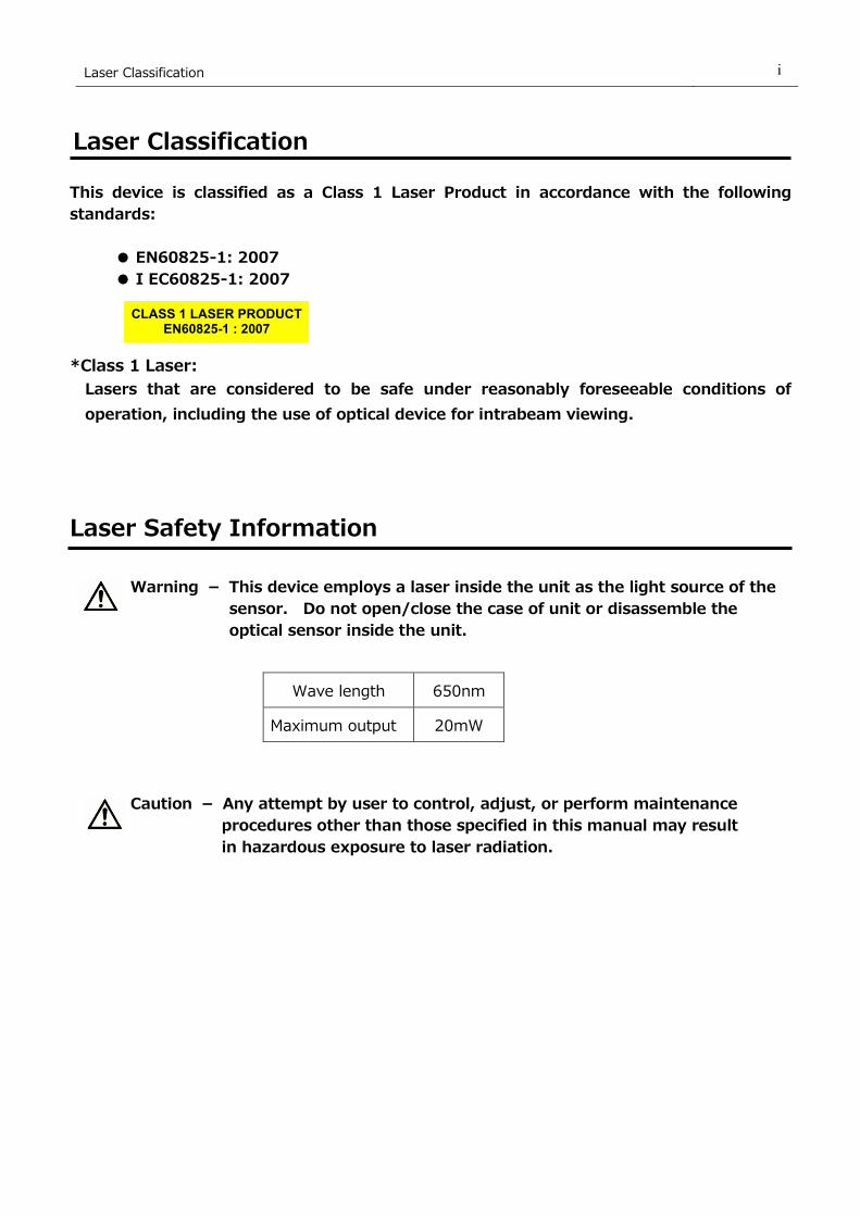
Laser Classification
This device is classified as a Class 1 Laser Product in accordance with the following
standards:
● EN60825-1: 2007
● I EC60825-1: 2007
*Class 1 Laser:
Lasers that are considered to be safe under reasonably foreseeable conditions of
operation, including the use of optical device for intrabeam viewing.
Laser Safety Information
Warning - This device employs a laser inside the unit as the light source of the
sensor. Do not open/close the case of unit or disassemble the
optical sensor inside the unit.
Caution - Any attempt by user to control, adjust, or perform maintenance
procedures other than those specified in this manual may result
in hazardous exposure to laser radiation.
Wave length 650nm
Maximum output 20mW
CLASS 1 LASER PRODUCT
EN60825-1 : 2007

Important Safety Information ii
Important Safety Information
The symbols for the warnings used in this manual are defined below:
Classifications
Warning:
Warnings in this classification indicate risks that may result in serious injury or death if not
observed.
Caution:
Warnings in this classification indicate risks that may result in damage to the product and
which may void the product warranty if not observed.
Description of Symbols
△ symbol indicates a condition that requires caution (including warning). The subject of
each caution is illustrated inside the triangle. (e.g. the high temperature caution symbol is
shown on the left.)
symbol indicates a prohibition. Do not take the prohibited action shown inside or near
this symbol. (e.g. the disassembly prohibition symbol is shown on the left.)
● symbol indicates a mandatory action. A specific action is given near the symbol.
Warning
○ Do not disassemble, modify, or attempt to repair the device.
…… A 3B laser diode is used as the optical source inside the device.
Never attempt to disassemble the device as it is potentially extremely
dangerous. Also, disassembling the unit may result in a
malfunction.
○ Use the device properly by carefully following this operation manual.
…… As with any electric device misuse may result in electric shock, fire,
damage to the instrument, etc.
Do not modify
or disassemble
Handle properly

Important Safety Information iii
○ If any abnormal noises, unusual odor or smoke is observed, or any liquid
is permitted to enter into the instrument, turn the power off immediately,
remove the battery or disconnect the power cable if connected.
…… These conditions may result in electric shock, fire, or damage to the
instrument. Contact your distributor.
Do not use this instrument in ambient temperature of 37℃ (99℉) or
greater.
…… The performance may deteriorate significantly and component damage
may result.
○ When the instrument is not in use, unplug the power cord.
…… Failure to observe the above may result in electric shock, fire or
damage to the internal circuit.
○ Install the instrument in a location where the power cord is accessible
such that you can disconnect the power cord easily.
○ When using the power cord, make sure that the plug is clean and dry.
○ The AC outlet must be within the specified power requirement.
…… Failure to observe the above may result in fire.
○ Use only the power cord and/or the AC adapter provided with this
instrument.
…… Other commercially available cords may have different voltage
specifications and polarity, which may result in short circuit, fire or
damage to the instrument.
Caution
○ Do not use or leave this instrument in an environment exceeding or
falling below the specified temperature/RH levels for the instrument.
The instrument should not be exposed to direct sunlight for a prolonged
period of time.
…… This instrument may not function properly beyond the specified
operable environment.
(5 to 35℃, 20 to 85%RH, with no condensation)
○ Do not use volatile solvents to clean the instrument.
…… The case of the main unit may be damaged by organic solvents.
Use a soft dry cloth to remove any dirt. If this is not effective, the user
may soak the cloth in neutral detergent or water and wipe the
instrument with the cloth.
Never use volatile solvents such as thinner or benzene.
Prohibited
installation
Prohibition
Prohibition

Important Safety Information iv
○ Do not subject the instrument to strong shocks. Do not place heavy
objects on the instrument.
…… Failure to observe the above may cause malfunction or damage to the
instrument.
○ If the instrument has been stored in a cold environment, allow the
instrument to come to temperature equilibrium with the environment in
which it will be operated before turning it on.
……Even when the instrument is used in the specified operating temperature
and humidity, a sudden temperature change may cause condensation.
Condensation on the sensor may cause inaccurate measurements or in
extreme situations, could damage the internal components.
○ Do not allow static electrical discharge to the instrument.
…… Failure to observe the above may affect the measurement value and
cause damage to the instrument circuitry.
○ Do not let the instrument draw in highly concentrated particles that
exceed the specification level. (i.e., >100,000 particles/cc)
○ Do not dispose of the instrument as Non-electronic waste.
…… Please note that any disposal of the instrument should be in line with
your local or national regulation.
For details, please contact your local distributor. Prohibition
Prohibition
Prohibition
Handle properly

Table of Contents
1. Part Names and Functions ................................................... 1
1.1 Main Unit .......................................................................................... 1
1.2 Software Screen ................................................................................ 2
2. Principle of Measurement .................................................... 4
2.1 Principle ........................................................................................... 4
3. Getting Started .................................................................... 5
3.1Recharging the Alcohol Cartridge ......................................................... 5
3.1.1 Preparation ............................................................................................. 5
3.1.2 Recharging the Alcohol Cartridge ................................................................ 6
3.1.3 Installing the Alcohol Cartridge ................................................................... 7
3.2 Getting Started (Main Unit) ................................................................. 8
3.2.1 Confirming the External Memory ................................................................ 8
3.2.2 Database Selection ................................................................................... 9
3.2.3 Particle Check .......................................................................................... 9
3.2.4 Zero Check .............................................................................................. 9
3.2.5 Fit Factor .............................................................................................. 10
3.2.6 Validation Check Settings ........................................................................ 10
3.3 Get the Person being Tested Ready .................................................... 10
4. Measurement .................................................................... 12
4.1 Step 1 ............................................................................................ 12
4.2 Step 2 ............................................................................................ 12
4.3 Step 3 ............................................................................................ 13
4.4 Step 4 .......................................................................................... 14
4.5 Record ........................................................................................... 14
4.6 Print ............................................................................................... 15
4.7 Real-time Measurement .................................................................... 15
4.8 Toolbox (Advanced Modes) ............................................................... 16
4.9 Remote Control Mode ....................................................................... 16
5. Administration and Setup .................................................. 17
5.1 Administration ................................................................................. 17

5.1.1 People .................................................................................................. 17
5.1.2 Respirators ............................................................................................ 17
5.1.3 Protocols ............................................................................................... 18
5.1.4 Fit Test Reports ..................................................................................... 19
5.1.5 Select Database ..................................................................................... 19
5.1.6 Toolbox ................................................................................................ 20
5.2 Setup ............................................................................................. 20
5.2.1 Printer Setup ......................................................................................... 20
5.2.2 Communication ...................................................................................... 20
5.2.3 Settings ................................................................................................ 23
5.2.4 Date and Time ....................................................................................... 23
5.2.5 Touch Screen Calibration ......................................................................... 24
5.2.6 Device Info ............................................................................................ 24
6.Maintenance ..................................................................... 25
6.1 Calibration ...................................................................................... 25
6.2 Alcohol Cartridge ............................................................................. 25
6.3 Mesh (Inlet) .................................................................................... 27
7. Specifications .................................................................... 28
8. Troubleshooting ................................................................ 29
9. Contact Information .......................................................... 31
1. Part Names and Functions 1
1. Part Names and Functions
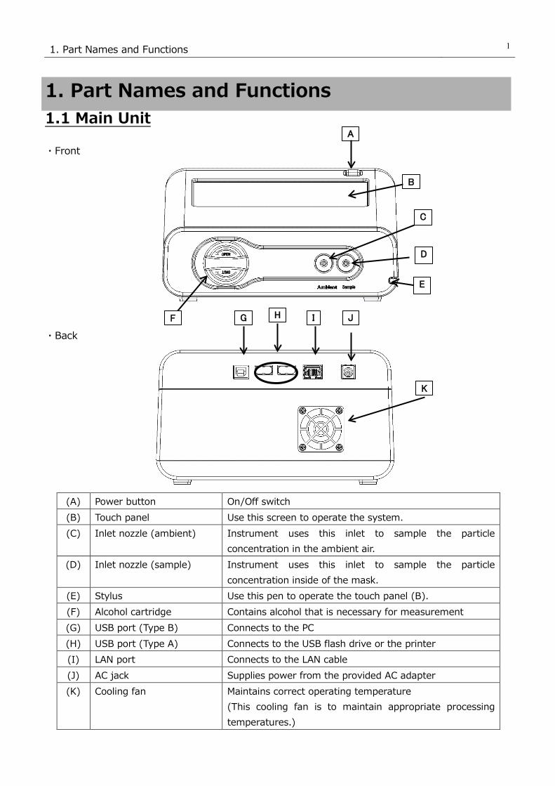
1.1 Main Unit
・Front
・Back
(A) Power button On/Off switch
(B) Touch panel Use this screen to operate the system.
(C) Inlet nozzle (ambient) Instrument uses this inlet to sample the particle
concentration in the ambient air.
(D) Inlet nozzle (sample) Instrument uses this inlet to sample the particle
concentration inside of the mask.
(E) Stylus Use this pen to operate the touch panel (B).
(F) Alcohol cartridge Contains alcohol that is necessary for measurement
(G) USB port (Type B) Connects to the PC
(H) USB port (Type A) Connects to the USB flash drive or the printer
(I) LAN port Connects to the LAN cable
(J) AC jack Supplies power from the provided AC adapter
(K) Cooling fan Maintains correct operating temperature
(This cooling fan is to maintain appropriate processing
temperatures.)
A
F
B
C
D
G H I J
K
E

1. Part Names and Functions 2
1.2 Software Screen
①Activities
(1) Fit Test Allows the user to perform respirator fit test
(2) Validation Check Allows user to conduct a system check prior to performing
series of measurements
(3) Realtime Displays the fit factor graph or particlulate concentration of
the ambient air on a real time basis
(4) Administration Proceeds to the screen ②
(Refer to 5. Administration and Setup for details.)
(5) Setup Proceeds to the screen ③
(Refer to 5. Administration and Setup for details.)
② Administration
(6) People Confirm and selects the list of people being tested.
Portal to enter a new person to database
(7) Respirators Confirm and selects the list of respirators
Portal to enter a new respirator to database
(1) (2) (3)
(4) (5)
(6) (7) (8)
(9) (10) (11)

1. Part Names and Functions 3
(8) Protocols Confirm, edit, and select the test protocol
Portal to enter a new test protocol to database
(9) Fit Test Reports Display and print the reports of conducted fit tests
(10) Select Database Select database to load as active; create new database
(11) Toolbox Proceed to the advanced mode
③ Setup
(12) Printer Setup Configure the printer setting
(13) Communication Configure and set the PC communication environment
(14) Settings Configure the settings for the device
(15) Date and Time Edit the date and time setting
(16) Touch Screen Calibration Calibrate the touch screen
(17) Device Info Check the device information
(12) (13) (14)
(15) (16) (17)

2. Principle of Measurement
4
2. Principle of Measurement
2.1 Principle This device measures particle concentration in the ambient air and inside of the mask, and
determines how well a mask fits by comparing the ratio of these particle concentrations. The
ratio of the above concentrations is called "fit factor". If the fit factor is 100, it essentially means
that the inside of the mask is 100 times as clean as the ambient air.
Fit factor=𝑃𝑃𝑃𝑃𝑃𝑃𝑃𝑃𝑃𝑃𝑃𝑃𝑃𝑃𝑃𝑃 𝑃𝑃𝑐𝑐𝑐𝑐𝑃𝑃𝑃𝑃𝑐𝑐𝑃𝑃𝑃𝑃𝑃𝑃𝑃𝑃𝑃𝑃𝑐𝑐𝑐𝑐 𝑃𝑃𝑐𝑐 𝑃𝑃ℎ𝑃𝑃 𝑃𝑃𝑎𝑎𝑎𝑎𝑃𝑃𝑃𝑃𝑐𝑐𝑃𝑃 𝑃𝑃𝑃𝑃𝑃𝑃𝑃𝑃𝑃𝑃𝑃𝑃𝑃𝑃𝑃𝑃𝑃𝑃𝑃𝑃𝑃𝑃 𝑃𝑃𝑐𝑐𝑐𝑐𝑃𝑃𝑃𝑃𝑐𝑐𝑃𝑃𝑃𝑃𝑃𝑃𝑃𝑃𝑃𝑃𝑐𝑐𝑐𝑐 𝑃𝑃𝑐𝑐𝑖𝑖𝑃𝑃𝑖𝑖𝑃𝑃 𝑐𝑐𝑜𝑜 𝑃𝑃ℎ𝑃𝑃 𝑎𝑎𝑃𝑃𝑖𝑖𝑚𝑚
In the older protocols, the device measures particle concentration in the ambient air twice in total,
before and after each mask fit test exercise. Particle concentration in the ambient air can be
variable over time; therefore this device measures the particle concentration in the ambient air
before and after each measurement, and uses the average value. The particle concentration in
the ambient air must be measured for the first measurement. For the second measurement and
subsequent measurements, the concentration after the previous measurement will be used and
there is no need for a redundant second measurement of the ambient air.
The sequence would thus be as follows:
Cambient // Cmask // Cambient // Cmask // Cambient …etc.
F: Fit factor
C b e f o r e:Particle concentration in the ambient air before measurement
C a f t e r:Particle concentration in the ambient air after measurement
C m a s k:Particle concentration inside of the mask
Note: Newer OSHA protocols approved in 2019 consist of 4 30-second exercises with the ambient
measurements taken before and after the complete suite of exercises. Empirical data show that
the ambient particulate concentration varies very little over two minutes, which is the time
required to perform the exercises. Careful observation shows that the preliminary value of the fit
factor for each exercise will change slightly as the test finishes when the two ambient values are
averaged.

3. Getting Started
5
3. Getting Started
3.1Recharging the Alcohol Cartridge
Isopropyl alcohol used for this device is a hazardous material.
Do not allow the alcohol to contact your eyes and skin.
Refer to the Safety Data Sheet (SDS) for chemical material when storing
alcohol in a special container and when using it.
Recap the alcohol container immediately after use to prevent the alcohol
from absorbing moisture and from evaporating.
The AccuFIT 9000 must be operated on a level surface, since tipping
the unit may allow alcohol to enter the optic bench.
The CPC (Condensation Particle Counter) in this device detects particles using isopropyl alcohol
vapor. Installing the alcohol cartridge soaked in the alcohol solution to this device will provide
the alcohol vapor in the CPC. When the alcohol vapor and an airborne particle come in contact,
a cloud which has the particle at its center will be formed. As this cloud passes into the
condenser the alcohol becomes tightly bound to the particle, thus increasing its diameter several
orders of magnitude. If the alcohol solution in the alcohol cartridge becomes depleted, the
device cannot measure particles correctly. To avoid this, please recharge the alcohol cartridge
before using the device.
3.1.1 Preparation
Isopropyl alcohol and the following components are required.
・Alcohol storage container
・Storage cap
・Alcohol cartridge
The isopropyl alcohol used for this device must be a high-purity guaranteed reagent alcohol.
Please do not use isopropyl alcohol that is available from pharmacies or supermarkets. The
purity of this alcohol is low (about 70%), and may cause damage to the CPC. Any problems
caused by a use of alcohol other than specified below is not covered by the warranty.
Please be sure to use the appropriate alcohol with strict adherence to the handling directions.
The alcohol used for this device must be a guaranteed reagent satisfying at least the following
requirements:
Chemical name: 2-Propanol
Synonym: Isopropyl alcohol
Chemical formula: (CH3)2CHOH
Formula weight: 60.10
Assay: 99.5% or better
Caution
Warning

3. Getting Started
6
When the device is not in use, the alcohol cartridge must be stored in the alcohol storage
container and the alcohol cartridge inlet must be sealed with the storage cap to keep
dust out.
When the device is in use, the storage cap must be used to seal the alcohol storage
container.
3.1.2 Recharging the Alcohol Cartridge
Do not leave the alcohol cartridge inlet open.
Failure to observe the above may cause contamination of the optical
system or a malfunction.
1. Turn the device off.
2. Open the alcohol storage container by turning the storage cap (or
the alcohol cartridge) about 45° counterclockwise.
Stand the storage cap (or the alcohol cartridge) straight up in a clean
place.
3. Pour isopropyl alcohol in the alcohol storage container up to the marked
level. Be careful not to tip the bottle and spill the alcohol prior to seating
the wick or storage cap, Once the wick assembly or storage cap is
seated securely in the capsule the alcohol will not leak.
4. Insert the alcohol cartridge into the alcohol storage container,
and turn it about 45° clockwise until it is firmly locked. Do not
use excessive force.
5. After the alcohol cartridge is inserted, the felt in the cartridge will be
soaked in alcohol. You can use the device after a few minutes of
soaking the felt in alcohol.
Fill level
Caution

3. Getting Started
7
3.1.3 Installing the Alcohol Cartridge
1. Remove the alcohol cartridge from the alcohol storage
container and gently shake off any excess alcohol solution.
Failure to do this may cause the absorbed alcohol to clog the
front of the alcohol cartridge. As a result, the flow of the
incoming airborne particles and alcohol vapor will be disturbed,
making it impossible to measure correctly.
Please wait until the outer surface of the alcohol cartridge dries
or wipe the excess alcohol off with a non-abrasive lint-free
wipe.
2. Insert the alcohol cartridge into the inlet as shown on the
right, and turn the alcohol cartridge clockwise about 45°.
To install the alcohol cartridge correctly, be sure to turn it
firmly until it stops. (See the picture at right.)
【Caution】 If alcohol accumulates inside the cartridge inlet, wipe
the alcohol off with a non-abrasive, lint-free wipe.
The front of the
Alcohol cartridge
3. Getting Started
8
・To prevent the alcohol from absorbing moisture and from evaporating,
always recap the alcohol storage container with the storage cap.
Contaminated alcohol must be disposed of.
・When the device is not in use, the alcohol cartridge must be stored in the
alcohol storage container. To keep the inside of the instrument clean, seal
the cartridge inlet with the storage cap.
・Do not carry or store the device with the alcohol cartridge installed.
Failure to observe the above may allow the alcohol solution to get into the
optical system and affect measurements. When carrying or storing the
device, seal the alcohol cartridge inlet with the storage cap to keep dust out.
・Always keep the storage cap and alcohol cartridge clean. (Refer to
6. Maintenance.) If dust sticks to the side of the cartridge or inside of the
cap, it may get into the device during operation, affecting measurtement.
・After measuring for a long period of time, alcohol may accumulate inside the
cartridge inlet. If you notice that the measured value of the ambient particle
concentration has shifted dramatically check the cartridge inlet, and wipe the
accumulated alcohol off with a non-abrasive, lint-free wipe before restarting
the device.
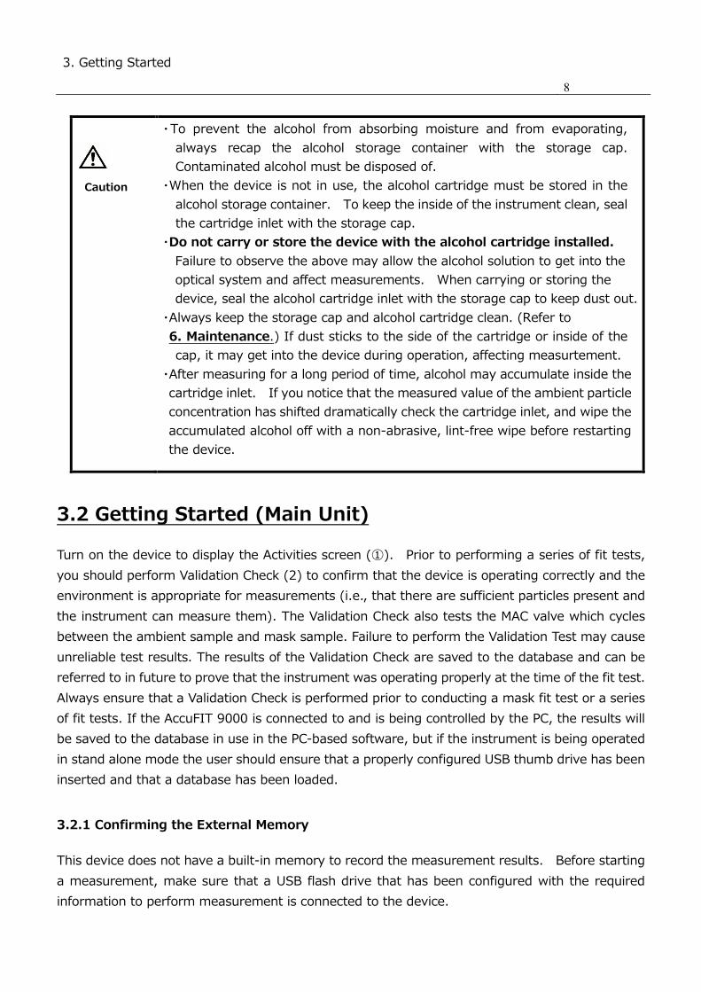
3.2 Getting Started (Main Unit)
Turn on the device to display the Activities screen (①). Prior to performing a series of fit tests,
you should perform Validation Check (2) to confirm that the device is operating correctly and the
environment is appropriate for measurements (i.e., that there are sufficient particles present and
the instrument can measure them). The Validation Check also tests the MAC valve which cycles
between the ambient sample and mask sample. Failure to perform the Validation Test may cause
unreliable test results. The results of the Validation Check are saved to the database and can be
referred to in future to prove that the instrument was operating properly at the time of the fit test.
Always ensure that a Validation Check is performed prior to conducting a mask fit test or a series
of fit tests. If the AccuFIT 9000 is connected to and is being controlled by the PC, the results will
be saved to the database in use in the PC-based software, but if the instrument is being operated
in stand alone mode the user should ensure that a properly configured USB thumb drive has been
inserted and that a database has been loaded.
3.2.1 Confirming the External Memory
This device does not have a built-in memory to record the measurement results. Before starting
a measurement, make sure that a USB flash drive that has been configured with the required
information to perform measurement is connected to the device.
Caution

3. Getting Started
9
3.2.2 Database Selection
Insert the USB flash drive into a USB port
Type A (H) of the device, prior to
performing Validation Check (2).
Select the desired database and tap [Load]
then tap [Fit Test] or [Exit] button.
By tapping the [Refresh] button, the
databases in the pull-down menu box will
be updated to display the databases
stored in the USB flash drive.
3.2.3 Particle Check Remove the HEPA filter or the mask if
attached, and tap the [Start] button to
check that the particle concentration in
the ambient air is sufficiently high enough
to calculate the mask fit factor.
Depending on the ambient particle
concentration (i.e., outside of the mask),
the environment may be inappropriate to
perform a mask fit test. This process also
confirms that the device is operating
properly. When this measurement is
complete, procede to the Zero Check

3. Getting Started
10
3.2.4 Zero Check
If a leak occurs in the sample train of the
device, the test result may be affected.
The Zero Check determines that there are
no internal leaks or loose connections.
Install the HEPA filter to the clear sample
inlet line (making sure that the arrow on
the HEPA cartridge is aligned with the
flow), and tap [Next] to begin the Zero
Check measurement. When the Zero
Check is complete the AccuFit 9000
automatically continues to the next check.
3.2.5 Fit Factor
To confirm whether the device performs
correctly, this test confirms the fit factor
using the HEPA filter. The instrument
measures the particle concentration in the
ambient air and calculates the ratio to the
particle concentration via the HEPA Filter.
By determining this ratio, the device
confirms that it is correctly performing this
function.
If the Validation Check is passed, a
message
"Test Passed" will appear. If no message
appears, perform Validation Check again.
*If there is no database, the alarm
appears. Execute the Save As command
from Toolbox (11) to create a database.
3. Getting Started
11
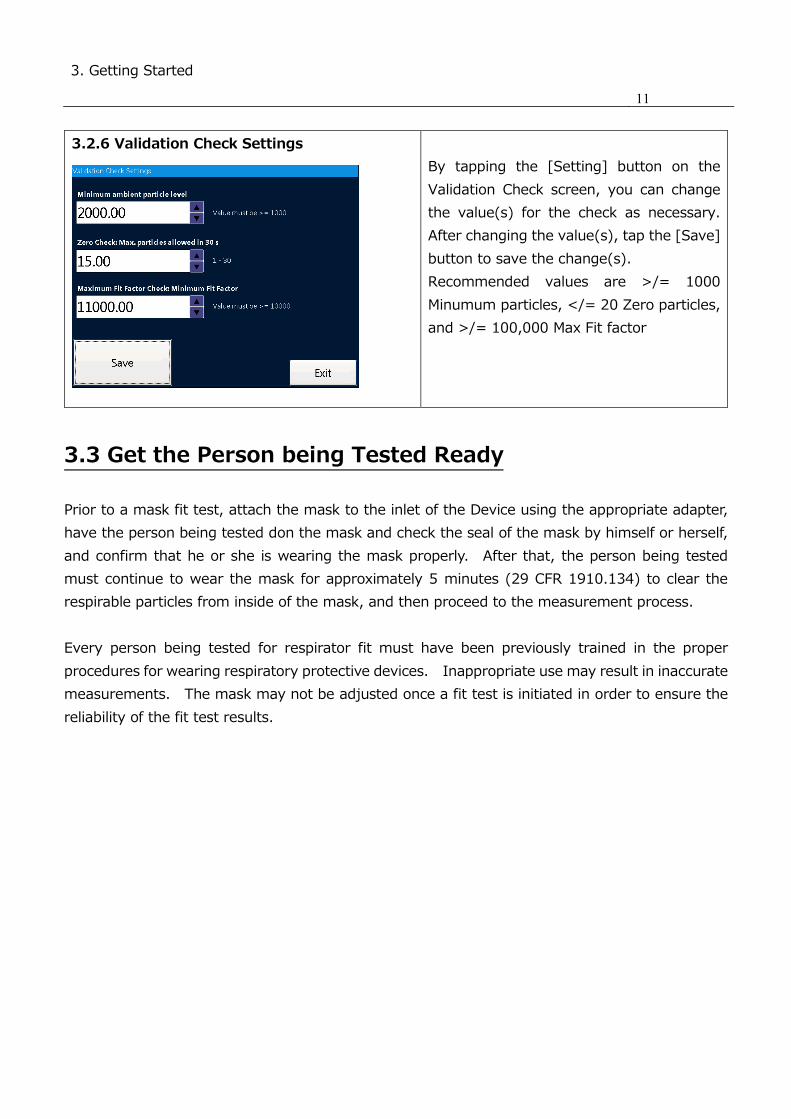
3.2.6 Validation Check Settings
By tapping the [Setting] button on the
Validation Check screen, you can change
the value(s) for the check as necessary.
After changing the value(s), tap the [Save]
button to save the change(s).
Recommended values are >/= 1000
Minumum particles, </= 20 Zero particles,
and >/= 100,000 Max Fit factor
3.3 Get the Person being Tested Ready
Prior to a mask fit test, attach the mask to the inlet of the Device using the appropriate adapter,
have the person being tested don the mask and check the seal of the mask by himself or herself,
and confirm that he or she is wearing the mask properly. After that, the person being tested
must continue to wear the mask for approximately 5 minutes (29 CFR 1910.134) to clear the
respirable particles from inside of the mask, and then proceed to the measurement process.
Every person being tested for respirator fit must have been previously trained in the proper
procedures for wearing respiratory protective devices. Inappropriate use may result in inaccurate
measurements. The mask may not be adjusted once a fit test is initiated in order to ensure the
reliability of the fit test results.

4. Measurement
12
4. Measurement
4.1 Step 1
Fit Test
Tap Fit Test icon (1) on the Activity
screen ① to start a measurement.
*If Validation Check (2) has not been
completed, the screen for the check
will be displayed.
Refer to 3.2 Getting Started (Main
Unit) to conduct the check prior to a
measurement.
SELECT PEOPLE
If the person to be tested is already
in the database, select the name from
the pull-down menu.
When the person is being tested for
the first time, or is not in your
database the subject's data must be
entered prior to the fit test.
Tapping the [New] button allows
these data to be entered. Use the
provided touch pen (stylus) and
display keypad to enter the personal
information.
When the entry is complete, tap the
[Save] button to finish the entry.
4.2 Step 2
Mask size
Select the size (Small, Medium,
Large, Other, or One Size Fits All)
Note: User may enter another size
(e.g., “Regular”) which will be saved
in the database, but which will not be
available in the drop-down menu.
SELECT RESPIRATOR
Select the mask to use for the test.
If the mask is already in the
database, you can select it. If the
mask is not already in the database it
must be entered prior to the test.

4. Measurement
13
4.3 Step 3
Confirming the measurement
parameters (Protocols)
Select the appropriate protocol.
Enter the name, initials, or ID of the
person conducting the fit test.
(Operator) (REMEMBER it’s your database so be consistent)
Check the next test date (Due Date)
The date of the next test is displayed.
(Per 29 CFR Part 1910.134 this would
be one year from current date.)

4. Measurement
14
4.4 Step 4
Start and Exit
The fit test exercises for the selected
protocol are displayed.
If not correct, tap the [Exit] button to
return to the previous page and select
the desired protocol. After
confirmation, tap the [Start] to start
the test.
When the test completes, the test
result (passed or failed) will be
displayed at the top of the screen.
The measurement result will be saved
automatically in the selected
database.
*If the test result is not passed and
there is reason to believe that there
may be a malfunction, refer to
8. Troubleshooting for details.
Tap the [Print] button to print the
result of the mask fit test.
To start a new test, tap the [New
Test] button.
*If there is no database, the alarm
appears. Execute the Save As
command from Toolbox (11) to create
a database.
To keep the inside of the device clean, attach the zero (HEPA) filter to the
inlet after using the device and run the AccuFIT9000 for approximately 5
minutes before turning the power off. Allowing the contaminated particles
to accumulate inside of the device could potentially cause trouble. When
the device is not in use, keep the zero filter attached to the inlet.
4.5 Record
After measurement, the data will be saved automatically into the active database on the USB flash
drive. If the AccuFIT9000 is used in Standalone mode data cannot be saved on the fit test
instrument by itself. To save data, use a USB flash drive that is configured with the database. If
Caution
4. Measurement
15
you do not have a USB flash drive, the device can perform measurements, but it can not record
the data.
4.6 Print
By connecting the device and the printer using a USB cable, you can print the measurement results.
You can configure printer setting from Printer Setup (12).
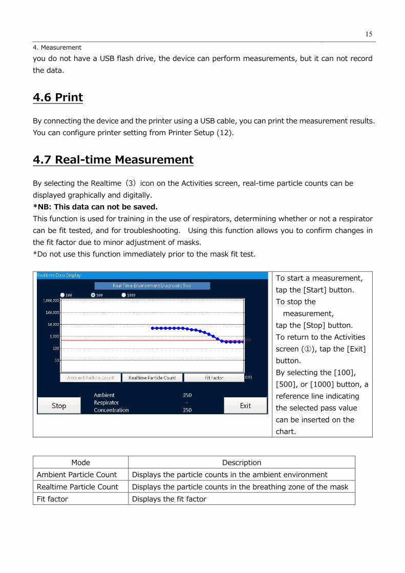
4.7 Real-time Measurement
By selecting the Realtime(3)icon on the Activities screen, real-time particle counts can be
displayed graphically and digitally.
*NB: This data can not be saved.
This function is used for training in the use of respirators, determining whether or not a respirator
can be fit tested, and for troubleshooting. Using this function allows you to confirm changes in
the fit factor due to minor adjustment of masks.
*Do not use this function immediately prior to the mask fit test.
To start a measurement,
tap the [Start] button.
To stop the
measurement,
tap the [Stop] button.
To return to the Activities
screen (①), tap the [Exit]
button.
By selecting the [100],
[500], or [1000] button, a
reference line indicating
the selected pass value
can be inserted on the
chart.
Mode Description
Ambient Particle Count Displays the particle counts in the ambient environment
Realtime Particle Count Displays the particle counts in the breathing zone of the mask
Fit factor Displays the fit factor

4. Measurement
16
4.8 Toolbox (Advanced Modes)
(11) Toolbox
Mode Functions
Clean Copy Copies data other than the fit test results from the original data base
Copy Copies all data saved in the database
Statistics Shows the number of records of each information type (Validation Check,
people, mask, protocol, fit test results) saved in the database and confirms
the file size
Save Stores the database in a USB flash drive. In the event that the
measurement data can not be saved in the USB flash drive in use, you can
use this command to save the measurement data in a substitute USB flash
drive.
Save As Creates and Stores a database by a different name from the current one.
When the device starts for the first time, there is a demo database only;
therefore, you can use this command to create and save a new database.
This command can also be used to create a backup database.
Delete Deletes data from the USB flash drive
Please note that the deleted data can not be restored.
4.9 Remote Control Mode
If the software for this device is installed in your PC, you can use your PC to remotely control the
device. For details, refer to the separately provided Software User Manual.

5. Administration and Setup 17
5. Administration and Setup
5.1 Administration
5.1.1 People
You can check the existing entry of
people. Select the person whose data
you wish to check from the pull-down
menu.
Tap the [New] button to start a new
entry as necessary.
For a new entry, the first name, last
name, and EMP.ID are required.
Enter the other information as desired.
Tap the [Create] button to allow these
data to be entered.
5.1.2 Respirators
You can review a mask that is already in
the database.
Select the mask to display the following
information: Manufacturer, Model, Type,
and Pass Value.
Tap the [New] button for a new entry as
necessary.

5. Administration and Setup 18
Enter information into the
[Manufacturer],
[Model], [Type], [Pass Value] fields, and
tap the [Save] button to confirm the
entry.
If the entry in each field is not
appropriate, tapping the [Save] button
will have no effect.
5.1.3 Protocols
You can check the mask fit test
protocols.
Select the protocol you wish to check
from the pull-down menu and tap the
[Display] button.
You can confirm the details of the
protocol
By checking the box at the bottom left
of the screen, you can modify
parameters of condition(s) to the mask
fit test.
5. Administration and Setup 19
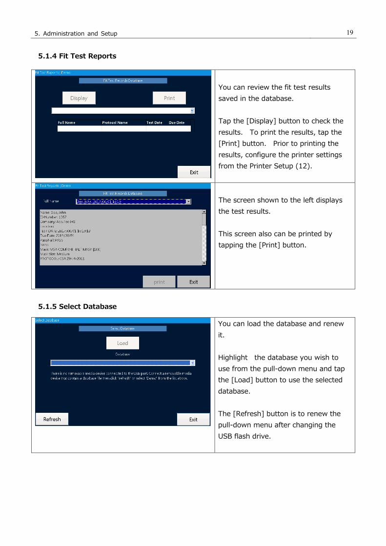
5.1.4 Fit Test Reports
You can review the fit test results
saved in the database.
Tap the [Display] button to check the
results. To print the results, tap the
[Print] button. Prior to printing the
results, configure the printer settings
from the Printer Setup (12).
The screen shown to the left displays
the test results.
This screen also can be printed by
tapping the [Print] button.
5.1.5 Select Database
You can load the database and renew
it.
Highlight the database you wish to
use from the pull-down menu and tap
the [Load] button to use the selected
database.
The [Refresh] button is to renew the
pull-down menu after changing the
USB flash drive.
5. Administration and Setup 20
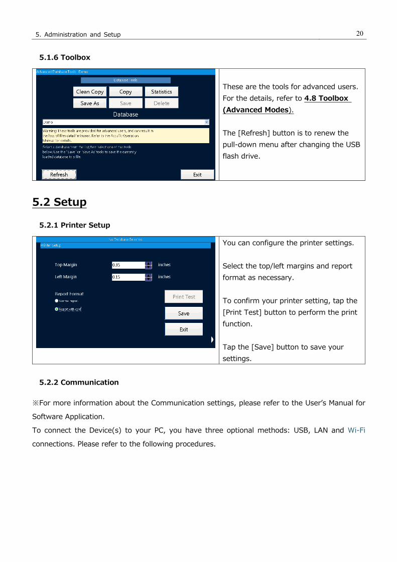
5.1.6 Toolbox
These are the tools for advanced users.
For the details, refer to 4.8 Toolbox
(Advanced Modes).
The [Refresh] button is to renew the
pull-down menu after changing the USB
flash drive.
5.2 Setup
5.2.1 Printer Setup
You can configure the printer settings.
Select the top/left margins and report
format as necessary.
To confirm your printer setting, tap the
[Print Test] button to perform the print
function.
Tap the [Save] button to save your
settings.
5.2.2 Communication
※For more information about the Communication settings, please refer to the User’s Manual for
Software Application.
To connect the Device(s) to your PC, you have three optional methods: USB, LAN and Wi-Fi
connections. Please refer to the following procedures.

5. Administration and Setup 21
PC Tool
You can select your desired
connection method by tapping the
appropriate button in the middle of
the screen (USB, LAN, or Wi-Fi).
For USB connection tap USB button.
For Wi-Fi or LAN connection to your
PC, enter IP Address of PC to the
Host field, and Port No. to the Port
field.
Note: Entering IP Address and Port
No. is necessary for LAN and Wi-Fi
connections, but not for USB
connection.
After you enter IP Address and Port
No., tap Save button to save the
data.
The status of the connection method
you selected will appear in the
Status text box. Typically, if you
have selected USB, the Status text
box will display “Not Connected”
until you select Validation Check or
Fit Test at the PC and then tap
“Connect” on the AccuFIT 9000.
Note: Windows ™ systems use a
resource management utility that
essentially “forgets” a USB
connection if the computer enters
the “sleep” mode. Simply unplug
either end of the USB connector and
reconnect.

5. Administration and Setup 22
LAN Connection
For LAN Connection, you are
required to enter IP Address, Subnet
Mask and Default Gateway.
If DHCP is enabled, select Obtain an
IP address via DHCP to obtain IP
Address, Subnet Mask and Default
Gateway automatically.
If DHCP is not enabled, select
Specify an IP address. Upon
confirming the network setting,
enter IP Address, Subnet Mask and
Default Gateway manually.
Selecting the appropriate text box
allows you to enter this required
information.
When you enter the required fields,
tap Save button to save the data.
And then tap Exit button to close
the Communication settings screen.
Wi-Fi Connection
Tap [search SSID] button, and
select SSID of wireless router you
use from the displayed list. Then
enter the password of SSID you
selected. Set Show password
characters to reveal the password
hidden behind asterisks. If DHCP is
enabled, select Obtain an IP
address via DHCP to obtain IP
Address, Subnet Mask and Default
Gateway automatically. If DHCP is
not enabled, select Specify an IP
address. Upon confirming the
5. Administration and Setup 23
network setting, enter IP Address,
Subnet Mask and Default Gateway
manually. Selecting appropriate text
box allows you to enter this required
information.
When you enter the required fields,
tap Save button to save the data.
Then tap Exit button to close the
Communication settings screen.
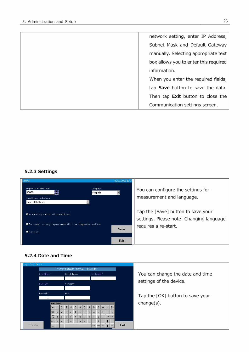
5.2.3 Settings
You can configure the settings for
measurement and language.
Tap the [Save] button to save your
settings. Please note: Changing language
requires a re-start.
5.2.4 Date and Time
You can change the date and time
settings of the device.
Tap the [OK] button to save your
change(s).

5. Administration and Setup 24
5.2.5 Touch Screen Calibration
You can calibrate the touch pen.
Tap the center of the cross icon on the
screen. Repeat tapping the center as
the cross icon moves around the screen.
When completed, the cross icon
disappears. Tap the screen to return
to the Setup screen (③).
5.2.6 Device Info
You can check the device information.

6. Maintenance 25
6.Maintenance This device requires routine maintenance according to the instruction below:
In addition, an annual calibration will ensure that the instrument is operating within
manufacturer's required parameters in order to perform accurate measurements. Please
contact your distributor for annual calibration.
6.1 Calibration
Do not attempt to calibrate this device by yourself. Contact your distributor.
Failure to observe the above may result in problems in measurements.
6.2 Alcohol Cartridge
The wick material inside of the alcohol cartridge absorbs and retains alcohol. The alcohol
cartridge is inserted into the main unit and therefore it must be kept clean. If dust gets into the
device, it may clog the internal nozzle and affect the proper operation. Be careful when storing
and handling the alcohol cartridge and storage cap to protect them from contamination.
・Cleaning and replacing the felt (wick material)
The wick material and mesh inside the alcohol cartridge are user-replaceable.
The device is provided with 2 sets of wicks and mesh. In normal use, there is no need for
replacing the wick material unless a problem described below occurs.
1. The wick material is contaminated with dust or oil.
→ This problem does not occur when the device is used in normal ambient air.
If the device is used for sampling highly-concentrated particles (e.g. sampling in a boiler
room or sampling combustion aerosols), the wick material may become contaminated
and will require replacement.
2. The mesh inside of the alcohol cartridge is clogged.
→ If the alcohol cartridge has been soaked in contaminated alcohol, the mesh inside
of the alcohol cartridge may be clogged. The mesh can be cleaned by washing;
however, if the clogging persists, the mesh must be replaced and the alcohol should be
checked.
DO NOT OPEN the outer case of the device.
It is hazardous to open the outer case of the device because a Class 3B
laser diode is contained in the device.
Opening the outer case will void the warranty.
For necessary maintenance or for any service that is not described in this
manual, please contact your distributor.
Warning

6. Maintenance 26
3. The device is not able to measure due to excess moisture in the alcohol.
→ Because of the fact that reagent grade 2-propanol is extremely hydroscopic, if
extremely humid air is drawn into the device, moisture may accumulate in the alcohol
cartridge and reduce the efficiency of the CPC. In this case, remove the wick material to
allow it to dry and replace it with the spare. When the moisture-contaminated felt is dry,
it can be re-used. If the wick material or mesh is obviously contaminated with something
other than moisture it must be replaced with one of the provided spares.
Over time, the felt may become discolored. Usually this will not cause a performance
problem.
・Checking and replacing the felt and mesh
1) To remove the wick from the cartridge, hold the cartridge at the joint line with both hands
and push the cap off the cylinder. The cartridge will be separated into the 2 parts, and
the white wick material will be visible (Figure 1).
2) After the cartridge is separated, use the wick removal tool (a small wooden stick) to push
the felt and mesh out of the cartridge cylinder (Figure 2).
3) Make sure that the wick and mesh are clean.
If no contamination is found on the wick, it can be reused. Dry the wick and reassemble
it.
If the wick is obviously contaminated, it must be replaced with the spare and disposed of.
Hold the mesh up to the light and confirm that all the holes of the mesh are open and
clear. If the mesh is clogged, clean air may be used to attempt to clear the mesh. If the
clogging persist, replace the mesh with the provided spare.
・Assembling the Cartridge
Before assembling, make sure that each part is clean.
If there is dust or debris stuck to the felt, it may get into the device and
cause several problems. Please confirm that there is no dust in the
alcohol cartridge or on the wick material.
Caution
1) Disassemble the Alcohol cartridge.
2) Remove the wick and mesh
from the cartridge cylinder.

6. Maintenance 27
Insert the clean mesh into the cartridge cylinder and confirm that the mesh lies flat on the
bottom of the cylinder. Insert the wick until it reaches the bottom of the cylinder, and
assemble the alcohol cartridge by reversing the steps shown above. The “O”-ring which holds
the cartridge cylinder should be lubricated with a VERY light coating of the Dow-Corning DC4
silicone lubricant found in the accessory kit. Simply touch the surface of the lubricant with
your index finger and apply a VERY light coating to the “O”-ring. Excessive lubricant will
degrade the performance of the instrument.
Finally, after the cartridge is fully assembled, blow air on the surface of the alcohol cartridge
to remove any dust particles.
6.3 Mesh (Inlet)
Over time, the mesh inside of the inlet may become clogged by dirt. Remove the inlet and
mesh for cleaning as necessary.
7. Specifications 28
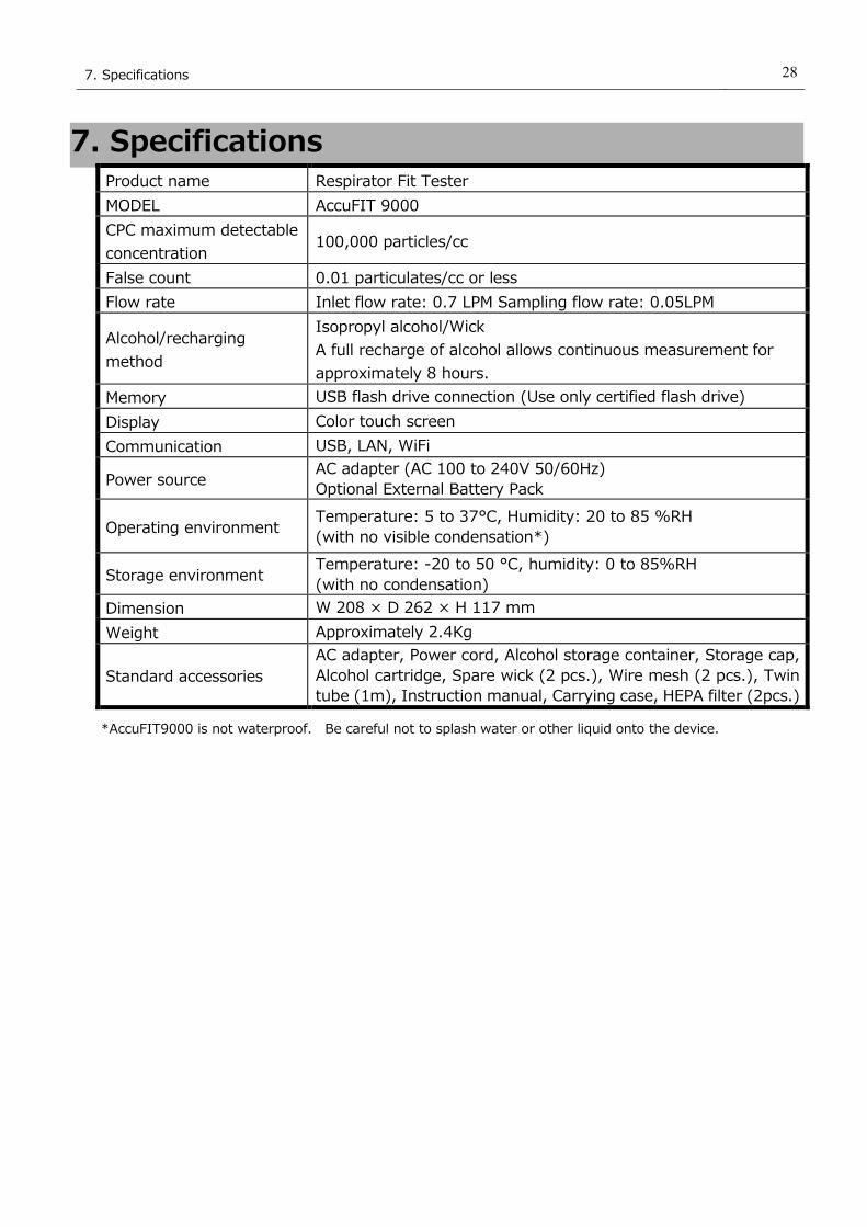
7. Specifications Product name Respirator Fit Tester
MODEL AccuFIT 9000
CPC maximum detectable
concentration 100,000 particles/cc
False count 0.01 particulates/cc or less
Flow rate Inlet flow rate: 0.7 LPM Sampling flow rate: 0.05LPM
Alcohol/recharging
method
Isopropyl alcohol/Wick
A full recharge of alcohol allows continuous measurement for
approximately 8 hours.
Memory USB flash drive connection (Use only certified flash drive)
Display Color touch screen
Communication USB, LAN, WiFi
Power source AC adapter (AC 100 to 240V 50/60Hz)
Optional External Battery Pack
Operating environment Temperature: 5 to 37°C, Humidity: 20 to 85 %RH
(with no visible condensation*)
Storage environment Temperature: -20 to 50 °C, humidity: 0 to 85%RH
(with no condensation)
Dimension W 208 × D 262 × H 117 mm
Weight Approximately 2.4Kg
Standard accessories
AC adapter, Power cord, Alcohol storage container, Storage cap,
Alcohol cartridge, Spare wick (2 pcs.), Wire mesh (2 pcs.), Twin
tube (1m), Instruction manual, Carrying case, HEPA filter (2pcs.)
*AccuFIT9000 is not waterproof. Be careful not to splash water or other liquid onto the device.

29
8. Troubleshooting
8. Troubleshooting
Symptom Possible Cause Troubleshooting
A count value is too
low (lower than
expected).
Alcohol depletion Recharge the alcohol cartridge with
alcohol. (Refer to 3.1 Recharging
the Alcohol Cartridge with
Alcohol.)
The actual particle count in the
ambient area is low. ―
Moisture has accumulated
inside the alcohol cartridge.
Replace the felt inside of the alcohol
cartridge or dry the felt.
(Refer to 6.2 Alcohol Cartridge.)
Pump has problems due to
low flow (or no flow).
Check the pump performance.
Check the touchscreen for an error
message.
Check the flow rate of the pump.
The flow rate must be approximately
700cc/min.
The device is being
operated in an environment
outside the specified operable
range.
Operate the device in the
specified environment.
(5 to 37℃, 20 to 85%RH, with no
condensation)
The alcohol is poor quality or
is contaminated.
Replace the wick inside the alcohol
cartridge. Use only the appropriate
alcohol.
(Refer to 6.2 Alcohol Cartridge.)
The mesh is clogged.
The mesh may be clogged with
excess alcohol. Remove the excess
alcohol.
(Refer to 6.2 Alcohol Cartridge.)
Dust and/or alcohol may have
gotten into the optical system.
Contact your distributor.
The device requires
calibration or service.
Contact your distributor.
【PD LD Error】
message
The optical system in the
main body is faulty.
Contact your distributor.
【Pump Error】
message
The pump in the main body
is faulty.
Contact your distributor.
【Peltier Error】
message
The Peltier device in the main
body is faulty.
Contact your distributor.

30
8. Troubleshooting
【Alcohol Error】
message
The amount of alcohol is low. Replenish the alcohol cartridge with
alcohol.
【Count Over】
message
Measurement concentration is
too high.
Ensure that ambient particle
concentration is 100,000 particles/cc
or less.
【Power Supply
Voltage Error】
message
Wrong AC adapter
is connected.
Make sure that the provided AC
adapter is connected.
The circuit in the main body
is fautly
Contact your distributor.

9. Contact Information 31
9. Contact Information
AccuTec-IHS, Inc.
1408 South Denver Ave Tulsa, OK 74119, USA
TEL: (800) 896-6959
URL: https://www.accutec-ihs.com/
E-Mail: [email protected]