ACCU 4560 MR - Welcome to Southern Automotive … Changers/Model 4560MR... · Page 4 ACCU 4560 MR...
21
ACCU 4560 MR ELECTRIC-HYDRAULIC TIRE CHANGER FOR MEDIUM AND LARGE SIZE TIRES INSTALLATION AND OPERATION INSTRUCTIONS SPARE PARTS EXPLODED VIEWS
Transcript of ACCU 4560 MR - Welcome to Southern Automotive … Changers/Model 4560MR... · Page 4 ACCU 4560 MR...

ACCU 4560 MR
ELECTRIC-HYDRAULIC TIRE CHANGERFOR MEDIUM AND LARGE SIZE TIRES
INSTALLATION AND OPERATION INSTRUCTIONSSPARE PARTS EXPLODED VIEWS
ACCU 4560 MR Operators Manual Page 3
Form 4560mr_e - Release B August 02ACCU reserves the right of modification without notice
TABLE OF CONTENTS
1.0 INTRODUCTION Page 41.1 USE LIMITATIONS Page 41.2 NOTICE Page 41.3 GENERAL SAFETY INSTRUCTIONS Page 41.4 NOMENCLATURE Page 41.5 SPECIFICATIONS Page 51.6 DIMENSIONS OF THE MACHINE Page 51.7 STANDARD ACCESSORIES Page 51.8 ACCESSORIES ON REQUEST Page 61.9 SAFETY PRECAUTIONS Page 71.10 SAFETY DEVICES Page 72.0 CARRIAGE INSTRUCTIONS Page 82.1 UNCRATING INSTRUCTIONS Page 82.2 INSTALLATION AREA Page 83.0 INSTALLATION INSTRUCTIONS Page 93.1 ELECTRIC INSTALLATION Page 93.2 MOTOR ROTATION CHECK Page 94.0 CONTROLS Page 105.0 MOUNTING AND DEMOUNTING - GENERAL PRECAUTIONS Page 115.1 LOCKING RIMS Page 115.2 DEMOUNTING TUBELESS TRUCK TIRES (UP TO 13 WIDE) Page 125.3 MOUNTING TUBELESS TRUCK TIRES (UP TO 13 WIDE) Page 145.4 DEMOUNTING DUPLEX AND SUPERSINGLE TUBELESS
TRUCK TIRES (OVER 13 WIDE) Page 165.5 MOUNTING DUPLEX AND SUPERSINGLE TUBELESS
TRUCK TIRES (OVER 13 WIDE) Page 175.6 DEMOUNTING TIRES FROM MULTI-PIECE RIM/WHEEL ASSEMBLIES Page 185.7 MOUNTING TIRES ONTO MULTI-PIECE RIM/WHEEL ASSEMBLIES Page 195.8 DEMOUNTING TRACTOR AND O.T.R. WHEELS
WITH ONE-PIECE RIMS Page 205.9 MOUNTING TRACTOR AND O.T.R. WHEELS
ON ONE-PIECE RIMS Page 226.0 MAINTENANCE Page 237.0 MOVING THE MACHINE Page 248.0 PUTTING THE MACHINE OUT OF SERVICE Page 249.0 SCRAPPING THE MACHINE Page 2410.0 TROUBLE SHOOTING Page 25

Page 4 ACCU 4560 MR Operators Manual
Form 4560mr_e - Release B August 02ACCU reserves the right of modification without notice
1.0 INTRODUCTION
Congratulations on purchasing the ACCU 4560 MRelectric-hydraulic tire changer.This tire changer is designed for ease of operation,safe handling of rims, reliability and speed.With a minimum of maintenance and care, yourtire changer will provide many years of trouble-freeoperation.Instructions on use, maintenance and operationalrequirements of the machine are covered in thismanual.
STORE THIS MANUAL IN A SAFE PLACEFOR FUTURE REFERENCE. READ THISMANUAL THOROUGHLY BEFOREUSING THE MACHINE.
1.1 USE LIMITATIONS
The ACCU 4560 MR model tire changer is intendedto be used as a device to demount and mounttubeless truck tires with the following specifications:
Maximum tire diameter: 2300 mm (90 ½)Maximum tire width: 1400 mm (55)
This device shall be used in the application forwhich it is specifically designed.Any other use shall be considered as improper,thus not reasonable.In particular, this device is not suitable to inflatetires. Inflation of tires shall be carried out in an ap-proved inflation safety cage.The manufacturer shall not be considered liable forpossible damage caused by improper, wrong ornon-reasonable use.
1.2 NOTICE
This manual is a part of the product.Read carefully the warnings and instructions of thismanual since they provide important informationconcerning safety and maintenance.
1.3 GENERAL SAFETY INSTRUCTIONS
THE USE OF THIS DEVICE IS ALLOWED ONLY TOPERSONNEL DULY TRAINED BY AN AUTHORIZEDACCU DEALER.
ANY MISUSE OR MODIFICATION OF THIS DEVICE OROF ITS PARTS OR COMPONENTS NOT PREVIOUSLYAUTHORIZED BY THE MANUFACTURER WAIVE THEMANUFACTURER FROM ANY DAMAGE CONSEQUENTOR RELATED TO THE ABOVE MENTIONED MISUSES.
REMOVING OR BYPASSING SAFETY DEVICES ORWARNING LABELS OF THE MACHINE IS A VIOLATIONOF THE SAFETY REGULATIONS.
THE USE OF THIS DEVICE IS ALLOWED ONLY INLOCATIONS WITH NO EXPLOSION OR FIRE HAZARD.
THIS EQUIPMENT IS DESIGNED TO RECEIVE ORIGINALSPARE PARTS AND ACCESSORIES ONLY.
THE INSTALLATION SHALL BE CARRIED OUT ONLY BYQUALIFIED PERSONNEL AND WITHIN THE SCOPE OFTHE INSTRUCTIONS PROVIDED IN THIS MANUAL.
CHECK FOR POSSIBLE DANGEROUS CONDITIONSDURING THE OPERATION OF THE MACHINE. IN SUCHA CASE STOP THE MACHINE IMMEDIATELY.IN CASE A DEFECTIVE FUNCTIONING CONDITION ISDETECTED, STOP USING THE MACHINE AND CALL THEAUTHORIZED ACCU DISTRIBUTOR FOR ASSISTANCE.
ALL ELECTRICAL CONNECTIONS SHALL BEPERFORMED BY A LICENCEDTECHNICIAN. ALL SERVICE MUST BEPERFORMED BY AN AUTHORIZED SERVICETECHNICIAN.
1.4 NOMENCLATURE
Before installing and using the tire changer it issuggested that you become familiar with the no-menclature of the machine's components (Fig.1).
764
Fig. 1

ACCU 4560 MR Operators Manual Page 5
Form 4560mr_e - Release B August 02ACCU reserves the right of modification without notice
1. 8 position switch2. Chuck switch3. Toolholder arm4. Main switch5. Toolholder carriage6. Footboard7. Jaws8. Self-centering chuck9. Chuck arm10. Chuck rotation control pedal11. Mount/demount tool12. Electric cabinet13. Toolholder arm switch
1.5 SPECIFICATIONS
Electric-hydraulic tire changer for tubeless truckwheels.
Weight with standard acc. 1032 kg(2270 lbs)Electric specifications 200VAC,3ph,60Hz,22AHydraulic motor power 1.5 kW (2 HP)Chuck rotation motor power 2.2-3 kW (3-4 HP)Chuck capacity 14 - 56Max. tire diameter 2300 mm (901/2)Max. tire width 1400 mm (55)Max. chuck torque 3100 Nm(2268 ftxlbs)Clamping power 60kNChuck rotation speed 4-7 rpmAcoustic pressure <70dBA
1.6 DIMENSIONS OF THE MACHINE
761
Fig. 2
1.7 STANDARD ACCESSORIES
#0001418 Shore tire tool#4004461 Long tire tool#4002354 Bead pushing lever
10001418 294
393 14004461
557 14002354
Fig.3
#14009472 Mounting clamp (Fig.4).To hold the bead when mounting tires on steel rims.Instructions for use is in section 5.3.
295
Fig.4

Page 6 ACCU 4560 MR Operators Manual
Form 4560mr_e - Release B August 02ACCU reserves the right of modification without notice
1.8 ACCESSORIES ON REQUEST
#14021852 Clamp for ligth-alloy rims (Fig.5).To hold the bead when mounting tires on light-alloyrims. Instructions for use is in section 5.3.
564
Fig.5
#14007611 O.T.R. Clamp(Fig.6)Useful when breaking the bead from the rim onmulti-piece wheels (O.T.R.).Instructions for use is in section 5.6.
396
Fig.6
#14008257 Protectors for alloy rims (Fig.7).Suitable for rims with a center hole of 220 and 280mm.
394
Fig.7
#14008264 Protectors for alloy rims (Fig.8)Suitable for rims with a center hole of 280 mm only.
667
Fig.8
#14014974 Tubeless roller (Fig.9).Facilitates mounting and dismounting tubeless tiresup to 13 wide.
395
Fig.9
#14019161 Extensions for 56 (Fig.9/A).Necessary when clamping rims without flange andwith a diameter exceeding 44.
443
Fig.9/A

ACCU 4560 MR Operators Manual Page 7
Form 4560mr_e - Release B August 02ACCU reserves the right of modification without notice
1.9 SAFETY PRECAUTIONS
A. BEFORE SERVICING ANY TIRES, WHEELS OR RIMSALL PERSONNEL SHOULD RECEIVE THOROUGHTRAINING FOR THE PROPER SERVICING OF TRUCKTIRES, WHEELS AND RIMS. CONSULT WITH YOURLOCAL CITY, COUNTRY STATE, AND NATIONALSAFETY AND HEALTH ADMISTRATIONS TO RECEIVECLARIFICATION OF ANY PUBLICATIONS AVAILABLEGOVERNING THIS SERIOUS MATTER.
B. DURING THE USE AND MAINTENANCE OF THEMACHINE IT IS MANDATORY TO COMPLY WITH ALLLAWS AND REGULATIONS FOR ACCIDENTPREVENTION.
C. THE ELECTRIC POWER SOURCE MUST HAVE AGROUND CABLE AND THE GROUND CABLE OF THEMACHINE (YELLOW WITH GREEN) MUST BECONNECTED TO THE GROUND CABLE OF THE POWERSOURCE.
D. BEFORE ANY MAINTENANCE OR REPAIRS AREACCOMPLISHED THE MACHINE MUST BEDISCONNECTED FROM THE ELECTRIC SUPPLY.
E. NEVER WEAR TIES, CHAINS OR OTHER LOOSEARTICLES WHEN USING, MAINTAINING ORREPAIRING THE MACHINE. LONG HAIR IS ALSODANGEROUS AND SHOULD BE KEPT UNDER A HAT.THE USER MUST WEAR PROPER SAFETY ATTIRE, I.E.GLOVES, SAFETY SHOES AND GLASSES.
F. MAINTAIN ALL ELECTRIC CORDS IN GOODREPAIR. G. KEEP SAFETY FEATURES IN PLACE AND INWORKING ORDER. H. KEEP WORKING AREA CLEAN. CLUTTERED AREASINVITE ACCIDENTS.
I. AVOID DANGEROUS ENVIRONMENTS. DONT USEPOWER TOOLS OR ELECTRICAL EQUIPMENT IN DAMPOR WET LOCATIONS, OR EXPOSE THEM TO RAIN.
L. NOBODY SHOULD BE ALLOWED TO STAND NEXTTO THE WHEEL, WHEN MOUNTING/DEMOUNTING ATIRE OR CLAMPING A WHEEL.
M. KEEP THE WORK AREA WELL LIGHTED.
N. PROPERLY ATTACH THE MACHINE TO THE FLOOR.
1.10 SAFETY DEVICES
This machine has several protectors to preventcompression or crushing hazards.There is a micro-switch protection under the chuckarm to prevent compression.The rotation speed of the chuck has been limitedto a maximum of 8 rpm to prevent dragging or en-trapping hazards.There is an emergency button on the portable con-trol unit.

Page 8 ACCU 4560 MR Operators Manual
Form 4560mr_e - Release B August 02ACCU reserves the right of modification without notice
2.0 CARRIAGE INSTRUCTIONS
The machine is crated in a wooden box of appro-priate strength.The box is mounted on a pallet.Handling of the machine must be performed withan appropriate lifting device (fork lift) (Fig.10).
321
Fig.10
2.1 UNCRATING INSTRUCTIONS
Uncrate the machine paying attention when re-moving the nails or during any other operationwhich may be hazardous.After removing the crate, check for any visibledamage to the machine and its components.If in doubt, call qualified personnel for assistance.The packing materials (plastic bags ,polystyrene,nails, screws, wood etc.) must be properly disposedof.Place the above-mentioned materials into a trashcontainer and dispose per local regulations.
ALWAYS WEAR GLOVES WHENUNCRATING THE MACHINE TOPREVENT SCRATCHES ORABRASIONS DUE TO THE CONTACTWITH PACKING MATERIALS.
2.2 INSTALLATION AREA
Install the machine in a covered and dry area.The installation of the machine requires a freespace of at least cm 500x500 (165x165) (Fig.11).
757
Fig.11
Make sure that from the operating position the usercan see all of the machine and the surroundingarea.The operator shall forbid, in such an area, the pres-ence of non-authorized persons and of objectswhich may create possible hazards.The machine shall be installed on a horizontal floor,preferably even. Do not install the machine on asinking or irregular floor.In case the machine is installed on a raised floor oron a service vehicle, the floor must have a capac-ity of at least 15000 N/m² (1500 kg/m² or 330 lbs xsqft ).
The machine must be secured to the floor throughthe holes provided in the cabinet. Expansionscrews 12x120 mm (or bolts 12x80mm) shall beused.Drill 12 mm holes in the floor flush with the holesprovided in the cabinet.Place the nogs into the holes drilled in the floor andmove the machine so that the holes of the cabinetare flush with the holes in the floor.Tighten the screws to 70 Nm (51 ftxlb).

ACCU 4560 MR Operators Manual Page 9
Form 4560mr_e - Release B August 02ACCU reserves the right of modification without notice
3.0 INSTALLATION INSTRUCTIONS
To install the machine proceed as follows:
A. Before raising the machine, ensure that thechuck is completely closed, that the chuck armis lowered and the toolholder carriage is in allthe way in Fig.12.
397
Fig.12
B. Remove the screws that secure the machine tothe pallet.
Lift the machine only with the two lifting lugs with abelt or rope of appropriate length and strength(300 cm - 10) (Fig.12).
DO NOT SWING THE MACHINE WHENLIFTED.DO NOT CUT THE REMOTE UNIT CORDWHEN LOWERING THE MACHINE TOTHE GROUND.
3.1 ELECTRIC INSTALLATION
ALL ELECTRICAL CONNECTIONSSHALL BE PERFORMED BY A LICENCEDTECHNICIAN. ALL SERVICE MUST BEPERFORMED BY AN AUTHORIZEDSERVICE TECHNICIAN.
Check on the plate of the machine that the elec-trical specifications of the power source are thesame as the machine.The machine uses 200VAC, 60 Hz, 3Ph, 22 Amp.Electrical specifications are clearly marked on alabel at the end of the electric cord.Before connecting the machine to the powersource, check that the power supply has an effi-cient grounding system.Connect the electric cord of the machine with atype approved plug.There should be less than 1 Ω between the groundpin and earth ground.
NOTE:The outlet installation must be verified by a licensedelectrician before connecting the tire changer.
NOTE:The yellow with green wire in the cord is thegrounding wire.Never connect the grounding wire to a live termi-nal.
Check that the power supply has an automaticcircuit breaker with a differential circuit set at 30mA.The electric motor operates in a wide voltagerange (plus 10% - minus 7%) and frequency range(50 or 60 cycles) and has a class of insulation suit-able for hot and moist climates.
3.2 MOTOR ROTATION CHECK
Once the machine is hooked-up, turn the machineon using the ON/OFF switch.Ensure that the rotation direction of the pump is thesame as indicated by the arrow on the motorcover.If not, reverse any two phase cables on the plug(i.e. reverse the brown and the blue cable).
ANY DAMAGE CAUSED BY THE NONAPPLICATION OF THE ABOVEINSTRUCTIONS SHALL NOT BE DEBITEDTO THE MANUFACTURER AND WILLVOID THE WARRANTY.

Page 10 ACCU 4560 MR Operators Manual
Form 4560mr_e - Release B August 02ACCU reserves the right of modification without notice
4.0 CONTROLS
Before operating the machine ensure that youhave well understood the operation and functionof all the controls.
1. To turn the machine on, rotate the ON/OFFswitch to position 1 and press the reset button:the pump motor starts turning and remains inoperation until the machine is turned off. Thepower required is minimum when the hydrauliccylinders are not in use.
NOTE:IT IS SUGGESTED TO TURN THE MACHINE OFF AFTEREVERY MOUNTING OR DEMOUNTING OPERATION, IFTHE TIME BEFORE THE NEXT OPERATION IS LONGERTHAN 5 MINUTES.
2. Press the chuck rotation pedal to the right: thechuck rotates clockwise. Press the other pedal:the chuck rotates counter clockwise.
3. Operate the control (#1 Fig.13) to position A:the chuck arm moves upwards.
Operate the control (#1 Fig.13) to position B: thechuck arm moves downwards.
4. Operate the control (#1 Fig.13) to position C:the toolholder carriage moves to the right.
Operate the control (#1 Fig.13) to position D: thetoolholder carriage moves to the left.
576
Fig.13
5. Operate the control (#2 Fig.13) to position A:the toolholder arm lifts and in the final stage ofthe movement, the tool rotates. Ensure that thearm is fully raised for complete rotation of thetool. If the tool is not required to rotate, lift thearm at only 3/4 of the movement.
6. Operate the control (#2 Fig.13) to position B: thetoolholder arm lowers and is properly blockedwhen the maximum pressure valve is activated,producing a characteristic hiss.
If the tool is required to rotate when the arm israised, lower the arm at about 1/4 of themovement and lift it again to engage the rota-tion mechanism.
7. Operate the control (#2 fig.13) to position C: thetoolholder carriage moves to the right.
Turn the switch to position D: the toolholder car-riage moves to the left.
8. By operating the controls in one of the diagonal
positions, the two adjacent movements areachieved simultaneously. This operation affordsconsiderable time saving in the intermediateoperations, but requires a little practice.
NOTE:IF ONE OF THE TWO HYDRAULIC MOVEMENTSREACHES THE END OF ITS COURSE, THE SPEED OF THEOTHER MOVEMENT IS APPRECIABLY REDUCED:INTERRUPT THE CONTROL ENGAGED AND OPERATEONLY THE DESIRED MOVEMENT IN ORDER TO GETNORMAL OPERATING SPEED.
BEFORE LIFTING THE TOOLHOLDER ARMBE SURE THAT NOBODY IS STANDING INTHE OPERATION AREA.
9. To open and close the chuck, operate the ap-propriate control (Fig.14).
762
Fig.14
WHEN OPENING THE CHUCK ENSURETHAT THE JAWS DO NOT HIT OTHERPARTS OF THE MACHINE.

ACCU 4560 MR Operators Manual Page 11
Form 4560mr_e - Release B August 02ACCU reserves the right of modification without notice
5.0 MOUNTING AND DEMOUNTING-GENERALPRECAUTIONS
BEFORE MOUNTING A TIRE ON A RIM, PAYATTENTION TO THE FOLLOWING:
A. THE RIM AND ALL ITS PARTS MUST BE CLEAN ANDIN GOOD CONDITION: IF NECESSARY CLEANAND PAINT IT AFTER REMOVING ALL WHEEL-WEIGHTS INCLUDING TAPE WEIGHTS INSIDE THERIM.
B. THE TIRE MUST BE CLEAN AND DRY, WITHOUT
ANY DAMAGE TO THE BEAD AND THE CARCASS. C. REPLACE THE RUBBER VALVE STEM WITH A NEW
ONE OR REPLACE THE O RING IF THE VALVESTEM IS MADE OF METAL.
D. IF THE TIRE REQUIRES A TUBE OR A FLAP, MAKE
SURE THE TUBE IS DRY AND IN GOODCONDITION.
E. LUBRICATION IS NECESSARY TO MOUNT THE TIRE
CORRECTLY AND GET A PROPER CENTERING. BESURE YOU ARE USING APPROVED LUBRICANTONLY.
F. MAKE SURE THE TIRE IS THE CORRECT SIZE FOR
THE RIM.
5.1 LOCKING RIMS
Lift the toolholder arm and move the toolholdercarriage all the way out.Put the wheel in vertically and roll it on the foot-board.Be sure to use alloy adapters when applicable.
ATTENTION!THE DROP CENTER OF THE RIM (WHEN IT EXISTS) MUSTBE KEPT TOWARDS THE OUTSIDE OF THE MACHINE(Fig.15).
402
Fig.15
IF THE WHEEL IS VERY HEAVY BE SURETO USE A SUITABLE EXTERNAL LIFTINGDEVICE (I.E. FORK LIFT, CRANE ETC.)
Close the jaws of the chuck and move the chuckapproximately to the center of the rim. Move thefootboard toward the chuck and move the chuckup-down while opening the chuck arms until therim is clamped properly (Fig.16).

Page 12 ACCU 4560 MR Operators Manual
Form 4560mr_e - Release B August 02ACCU reserves the right of modification without notice
600
601
602
603
Fig.16
5.2 DEMOUNTING TUBELESS TRUCK TIRES(UP TO 13 WIDE)
The tubeless truck tires are mounted on drop-center rims with a conical base. It is possible todemount these tires simply by pressure, with aproper lubrication (Fig.17).
297
Fig.17
1. Remove all wheel-weights from the rim. Remove the valve stem or core and deflate the tire. 2. Position the bead breaker disc or tubeless roller
(option) as shown in Fig.18, Fig.19.
578
Fig.18

ACCU 4560 MR Operators Manual Page 13
Form 4560mr_e - Release B August 02ACCU reserves the right of modification without notice
579
Fig.19
3. Lift or lower the chuck so that the bead breakerdisc or tubeless roller remains close to the rimedge. Turn the chuck counter-clockwise and atthe same time shift the toolholder carriage step-by-step toward the inside to demount the tire.
Continue to turn the chuck and lubricate the beadand the rim liberally with an approved lubricant.
USE ONLY SPECIFIC LUBRICANTS FORTIRES AND WHEELS.APPROVED LUBRICANTS DO NOTCONTAIN WATER, PETROLEUMPRODUCTS/HYDROCARBONS ORSILICONE.
4. Raise the toolholder arm to the rest position.
5. Move the toolholder arm all the way in.Lower the arm and secure.Bring the tool in contact with the inner bead.
6. Break the inner bead as described in point #3above.
7. Continue rotating the chuck, moving toolholdercarriage towards the outside until the beads aredemounted from the rim (Fig.20 and Fig.21)
580
Fig.20
581
Fig.21
Page 14 ACCU 4560 MR Operators Manual
Form 4560mr_e - Release B August 02ACCU reserves the right of modification without notice
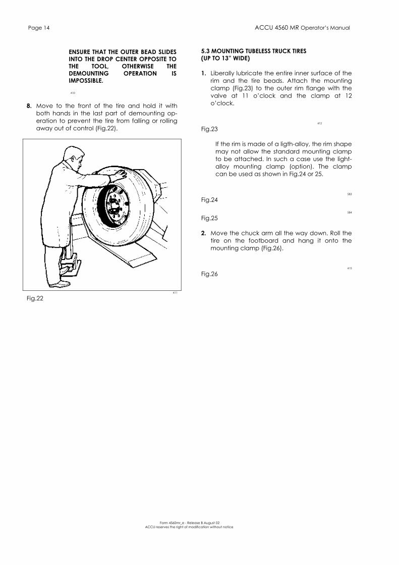
ENSURE THAT THE OUTER BEAD SLIDESINTO THE DROP CENTER OPPOSITE TOTHE TOOL, OTHERWISE THEDEMOUNTING OPERATION ISIMPOSSIBLE.
410
8. Move to the front of the tire and hold it withboth hands in the last part of demounting op-eration to prevent the tire from falling or rollingaway out of control (Fig.22).
411
Fig.22
5.3 MOUNTING TUBELESS TRUCK TIRES(UP TO 13 WIDE)
1. Liberally lubricate the entire inner surface of therim and the tire beads. Attach the mountingclamp (Fig.23) to the outer rim flange with thevalve at 11 oclock and the clamp at 12oclock.
412
Fig.23
If the rim is made of a ligth-alloy, the rim shapemay not allow the standard mounting clampto be attached. In such a case use the light-alloy mounting clamp (option). The clampcan be used as shown in Fig.24 or 25.
583
Fig.24
584
Fig.25
2. Move the chuck arm all the way down. Roll thetire on the footboard and hang it onto themounting clamp (Fig.26).
415
Fig.26

ACCU 4560 MR Operators Manual Page 15
Form 4560mr_e - Release B August 02ACCU reserves the right of modification without notice
3. Lift the chuck arm and position the mountinghook or tubeless roller approximately 1.5 cm (½) to the inside of the rim edge and approx.1.5 cm( ½) away from the rim edge (Fig.27).
The mounting clamp is at 11 oclock approxi-mately.
416
Fig.27
NEVER USE HAND PRESSURE TO HOLDTHE TIRE ONTO THE RIM.
4. Turn the chuck clockwise until the tire is com-pletely mounted (Fig.28).
417
Fig.28
ENSURE THAT THE OUTER BEADDESCENDS INTO THE DROP CENTERWHEN THE CLAMP IS OPPOSITE TO THETOOL.
423
STOP THE CHUCK BEFORE ONECOMPLETE TURN IS MADE TO AVOIDSERIOUS DAMAGE TO THE MOUNTINGCLAMP AND TO THE RIM.
DO NOT INFLATE THE TIRE ON THEMACHINE. THIS MACHINE IS NOT ANINFLATION DEVICE.FOR INFLATION PLACE THE WHEEL INAN APPROVED INFLATION RESTRAINTDEVICE (IN THE UNITED STATES OFAMERICA CONSULT O.S.H.A.REGULATIONS CONCERNING THEPROPER SERVICING OF TRUCKWHEELS AND RIMS).

Page 16 ACCU 4560 MR Operators Manual
Form 4560mr_e - Release B August 02ACCU reserves the right of modification without notice
5.4 DEMOUNTING DUPLEX AND SUPERSINGLETUBELESS TRUCK TIRES (OVER 13" WIDE)
NOTE:FOR THIS OPERATION THE MOUNT/DEMOUNT TOOLIS REQUIRED.
1. Break the bead of the tire as described in#5.2.1.- 5.2.6.
2. For this type of tire it is not possible to demountboth beads at the same time as described in#5.2.7.
Engage the hook of the mount/demount tool be-tween the bead and the rim.
3. Lift the chuck arm enough to clear the hook 2-3cm (1"-1"1/2) from the rim flange. Move themount/demount tool towards the outside. Thiswill allow you to place the long bar in betweenthe bead and the rim flange for necessary pry-ing (Fig.29).
418
Fig.29
4. Rotate the chuck counter clockwise until theouter bead is completely demounted (Fig.30).
585
Fig.305. Demount the inner bead with the bead breaker
disc, as described in @5.2.7. (Fig.31).
580
Fig.31
5.5 MOUNTING DUPLEX AND SUPERSINGLE TUBELESSTRUCK TiRES (OVER 13" WIDE)
1. Hang the inner bead of the tire on the mountingclamp (Fig.32).
420
Fig.32
2. Position the mounting hook about 3/4" (1.5 cm)to the inside of the rim edge and 1/2" (1 cm)away radially. Rotate the chuck clockwise.Normally less than 1/4 of a revolution is sufficientto mount the first bead (Fig.33).
586
Fig.33
3. Reattach the mounting clamp to the rim flangewith the valve after the mounting clamp, fol-lowing the rotation direction (Fig.34).
416
Fig.34
4. Rotate the chuck clockwise until the tire is com-pletely mounted.
Ensure that outer bead descends into the dropcenter when the clamp is opposite to themount/demount tool (Fig.35).
423
Fig.35

ACCU 4560 MR Operators Manual Page 17
Form 4560mr_e - Release B August 02ACCU reserves the right of modification without notice
NEVER USE HAND PRESSURE TO HOLDTHE TIRE INTO THE RIM.
STOP THE CHUCK BEFORE ONECOMPLETE TURN IS MADE TO AVOIDSERIOUS DAMAGE TO THE MOUNTINGCLAMP AND TO THE RIM.
DO NOT INFLATE THE TIRE ON THEMACHINE. THIS MACHINE IS NOT ANINFLATION DEVICE.FOR INFLATION PLACE THE WHEEL INAN APPROVED INFLATION RESTRAINTDEVICE (IN THE UNITED STATES OFAMERICA CONSULT O.S.H.A.REGULATIONS CONCERNING THEPROPER SERVICING OF TRUCK,WHEELS AND RIMS).
5.6 DEMOUNTING TIRES FROM MULTI-PIECERIM/WHEEL ASSEMBLIES
The multi-piece rim/wheel assembly can be in twoor more pieces (Fig.36).
424
425
Fig.36
1. Remove all wheel-weights from the rim.Remove the valve stem or core and deflate the
tire.
2. Position the tool close to the rim edge (Fig.37).When the lock ring is stuck to the bead, (on theO.T.R. tires) to make it to break the bead, it isnecessary to hold it to the rim with the appro-priate clamp #4007611 (on request).
426
Fig.373. Turn the chuck counter-clockwise and the
break bead as described in @5.2.1.-5.2.3.Do not lubricate.
4. To remove the lock ring, squeeze one edge withthe proper bar and place the bead breakerdisc as shown in Fig.38.
587
Fig.38
5. Turn the chuck clockwise (or counter-clockwise)until the lock ring is completely removed.
NO ONE SHOULD STAND IN FRONT OFTHE WHEEL WHEN REMOVING THELOCK RING.
Continue to demount all components of the rimmanually or with the disc tool.
6. When breaking the inner bead be sure not todamage the valve stem (Fig.39).
580
Fig.395.7 MOUNTING TIRES ONTO MULTI-PIECE RIM/WHEELASSEMBLIES
1. Roll the tire on the footboard (the tube and flapmust be in place).
NOTE:O.T.R. TIRES AND RIMS ARE VERY HEAVY AND ANOUTSIDE LIFTING TOOL MAY BE REQUIRED.
For tube type only, the valve should be placed at12 o'clock, for easier mounting.
2. Slide the tire onto the rim with the footboard orwith the bead breaker disc, if necessary.
3. Mount all the assembly components.
4. Engage one edge of the lock ring in its seat andcomplete the mounting process with the beadbreaker disc.
In the initial mounting phase hold the rim edge in itsseat with a bar (Fig.40).
588
Fig.40
DO NOT INFLATE THE TIRE ON THEMACHINE. THIS MACHINE IS NOT ANINFLATION DEVICE.FOR INFLATION PLACE THE WHEEL INAN APPROVED INFLATION RESTRAINTDEVICE (IN THE UNITED STATES OFAMERICA CONSULT O.S.H.A.REGULATIONS CONCERNING THEPROPER SERVICING OF TRUCK,WHEELS AND RIMS).
Page 18 ACCU 4560 MR Operators Manual
Form 4560mr_e - Release B August 02ACCU reserves the right of modification without notice
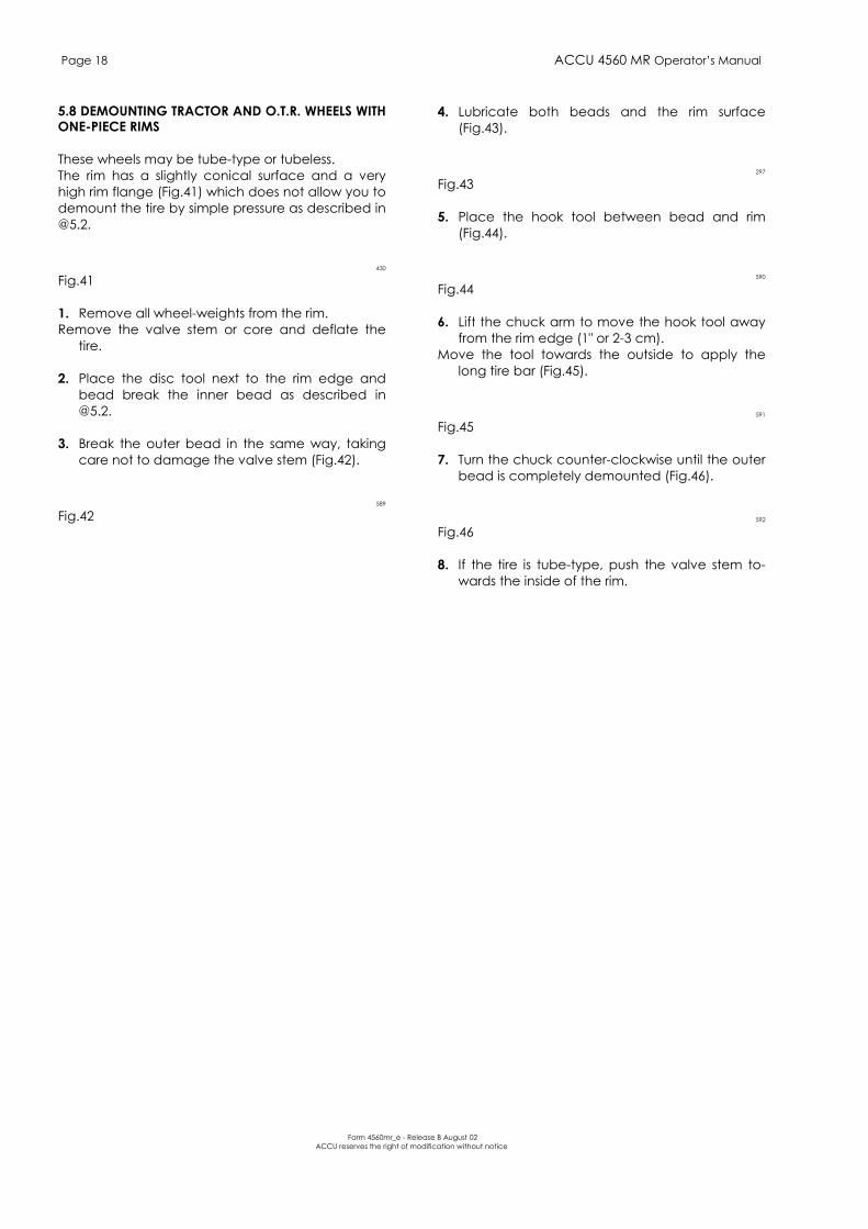
5.8 DEMOUNTING TRACTOR AND O.T.R. WHEELS WITHONE-PIECE RIMS
These wheels may be tube-type or tubeless.The rim has a slightly conical surface and a veryhigh rim flange (Fig.41) which does not allow you todemount the tire by simple pressure as described [email protected].
430
Fig.41
1. Remove all wheel-weights from the rim. Remove the valve stem or core and deflate the
tire. 2. Place the disc tool next to the rim edge and
bead break the inner bead as described [email protected].
3. Break the outer bead in the same way, taking
care not to damage the valve stem (Fig.42).
589
Fig.42
4. Lubricate both beads and the rim surface(Fig.43).
297
Fig.43
5. Place the hook tool between bead and rim(Fig.44).
590
Fig.44
6. Lift the chuck arm to move the hook tool awayfrom the rim edge (1" or 2-3 cm).
Move the tool towards the outside to apply thelong tire bar (Fig.45).
591
Fig.45
7. Turn the chuck counter-clockwise until the outerbead is completely demounted (Fig.46).
592
Fig.46
8. If the tire is tube-type, push the valve stem to-wards the inside of the rim.

ACCU 4560 MR Operators Manual Page 19
Form 4560mr_e - Release B August 02ACCU reserves the right of modification without notice
9. Lift the toolholder arm to the rest position.Shift the tire from the rim, moving the toolholder
carriage towards the outside: this will make itmuch easier to extract the tube (Fig.47).
593
Fig.47
10. Place the hook tool as in Fig.48.The edge of the hook should be about 2-3 cm (1")
away radially from the rim edge and about 2-3cm (1") to the outside.
594
Fig.48
11. Put the long tire bar in between the bead andthe rim.
12. Rotate the chuck counter-clockwise until the
tire is completely demounted.
DURING THE FINAL PHASE OF THEDEMOUNTING OPERATION REMOVE THETIRE BAR AND HOLD THE TIRE WITH BOTHHANDS, IN ORDER TO KEEP IT IN AVERTICAL POSITION.
5.9 MOUNTING TRACTOR AND O.T.R. WHEELS ONONE-PIECE RIMS
1. Liberally lubricate both beads and the rim.
2. Firmly fit the mounting clamp to the outer rimflange at 9 o'clock.
Roll the tire onto the footboard and hang it on themounting clamp attached to the rim edge.
3. Place the hook tool as shown in Fig.49. The edge of the hook should be about 2-3 cm (1")
away radially from the rim edge and 2-3 cm (1")to the outside.
595
Fig.49 4. Turn the chuck clockwise until the first bead is
mounted. Remove the clamp.
5. Place the tube (if any) in the tire and secure thevalve stem to the rim.
6. Firmly fit the mounting clamp to the outer rimedge at 11 o'clock with valve stem at 10 o'clockin such a way as to hold the outer bead. If nec-essary make use of the tool to create the spaceto fit the clamp.
Page 20 ACCU 4560 MR Operators Manual
Form 4560mr_e - Release B August 02ACCU reserves the right of modification without notice
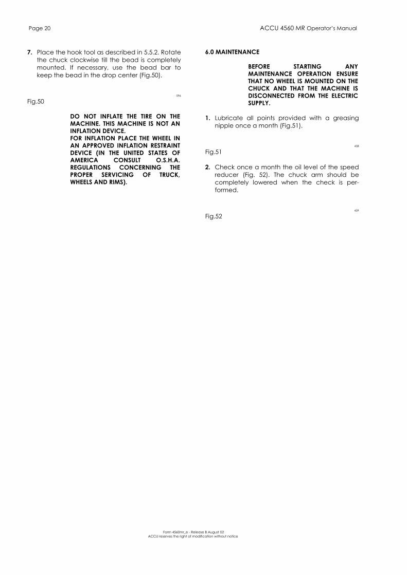
7. Place the hook tool as described in 5.5.2. Rotatethe chuck clockwise till the bead is completelymounted. If necessary, use the bead bar tokeep the bead in the drop center (Fig.50).
596
Fig.50
DO NOT INFLATE THE TIRE ON THEMACHINE. THIS MACHINE IS NOT ANINFLATION DEVICE.FOR INFLATION PLACE THE WHEEL INAN APPROVED INFLATION RESTRAINTDEVICE (IN THE UNITED STATES OFAMERICA CONSULT O.S.H.A.REGULATIONS CONCERNING THEPROPER SERVICING OF TRUCK,WHEELS AND RIMS).
6.0 MAINTENANCE
BEFORE STARTING ANYMAINTENANCE OPERATION ENSURETHAT NO WHEEL IS MOUNTED ON THECHUCK AND THAT THE MACHINE ISDISCONNECTED FROM THE ELECTRICSUPPLY.
1. Lubricate all points provided with a greasingnipple once a month (Fig.51).
438
Fig.51
2. Check once a month the oil level of the speedreducer (Fig. 52). The chuck arm should becompletely lowered when the check is per-formed.
439
Fig.52
ACCU 4560 MR Operators Manual Page 21
Form 4560mr_e - Release B August 02ACCU reserves the right of modification without notice
3. Check hydraulic oil level once a month (Fig.53).
599
Fig.53
NOTE:BEFORE CHECKING, ALL CYLINDERS MUST BECOMPLETELY RETRACTED.
If necessary add:ESSO : Nuto H 46SHELL : Tellus oil 46TOTAL : Azolla 46
Oil change is not required.
4. Clean and grease once a month the sliding barof the toolholder arm (Fig.54).
440
Fig.54
5. Clean the jaws of the chuck with a wire brushonce a month.
7.0 MOVING THE MACHINE
In case the machine is to be moved from a work-ing place to another, proceed as follows:
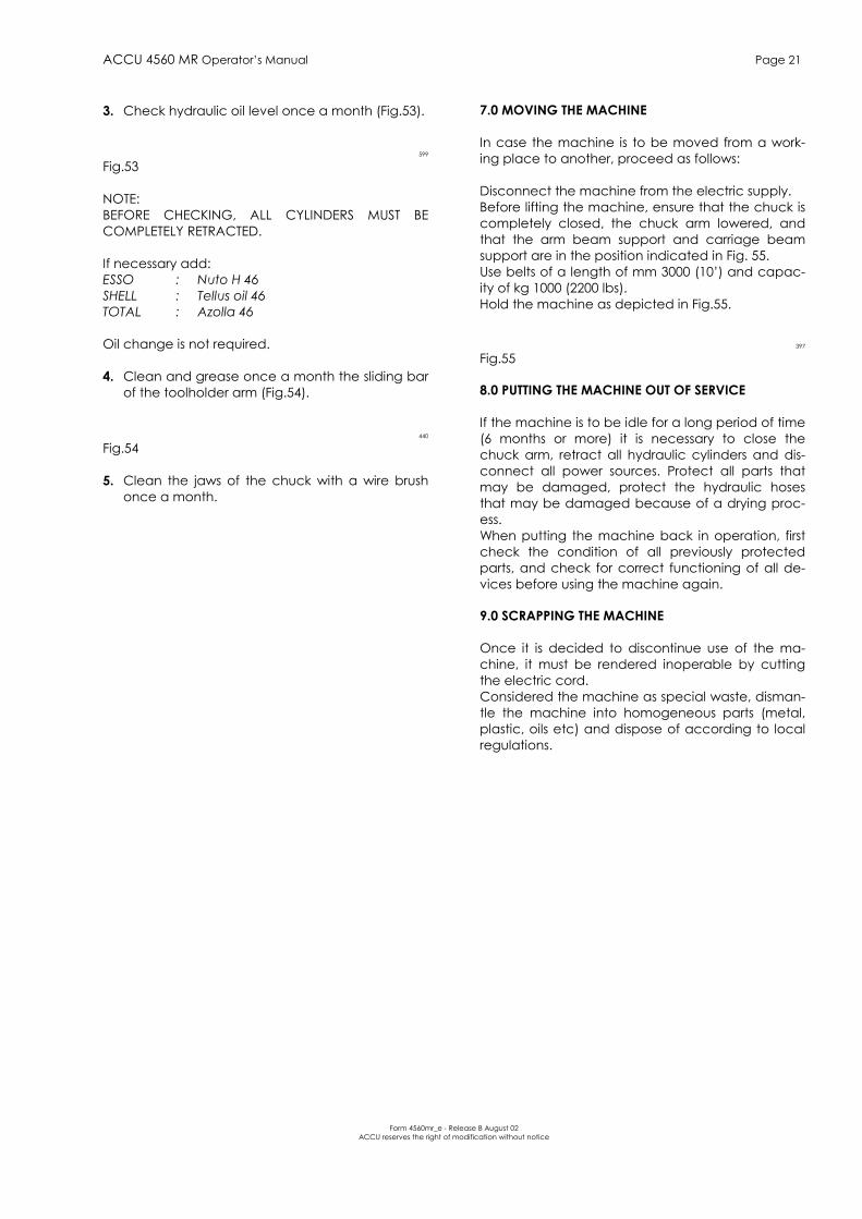
Disconnect the machine from the electric supply.Before lifting the machine, ensure that the chuck iscompletely closed, the chuck arm lowered, andthat the arm beam support and carriage beamsupport are in the position indicated in Fig. 55.Use belts of a length of mm 3000 (10) and capac-ity of kg 1000 (2200 lbs).Hold the machine as depicted in Fig.55.
397
Fig.55
8.0 PUTTING THE MACHINE OUT OF SERVICE
If the machine is to be idle for a long period of time(6 months or more) it is necessary to close thechuck arm, retract all hydraulic cylinders and dis-connect all power sources. Protect all parts thatmay be damaged, protect the hydraulic hosesthat may be damaged because of a drying proc-ess.When putting the machine back in operation, firstcheck the condition of all previously protectedparts, and check for correct functioning of all de-vices before using the machine again.
9.0 SCRAPPING THE MACHINE
Once it is decided to discontinue use of the ma-chine, it must be rendered inoperable by cuttingthe electric cord.Considered the machine as special waste, disman-tle the machine into homogeneous parts (metal,plastic, oils etc) and dispose of according to localregulations.
Page 22 ACCU 4560 MR Operators Manual
Form 4560mr_e - Release B August 02ACCU reserves the right of modification without notice
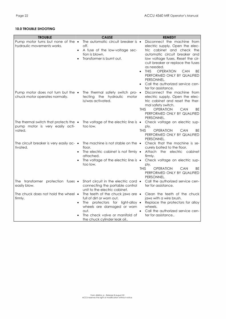
10.0 TROUBLE SHOOTING
TROUBLE CAUSE REMEDYPump motor turns but none of thehydraulic movements works.
• The automatic circuit breaker isoff.
• A fuse of the low-voltage sec-tion is blown.
• Transformer is burnt out.
• Disconnect the machine fromelectric supply. Open the elec-tric cabinet and check theautomatic circuit breaker andlow voltage fuses. Reset the cir-cuit breaker or replace the fusesas needed.
• THIS OPERATION CAN BEPERFORMED ONLY BY QUALIFIEDPERSONNEL.
• Call the authorized service cen-ter for assistance.
Pump motor does not turn but thechuck motor operates normally.
• The thermal safety switch pro-tecting the hydraulic motoris/was activated.
• Disconnect the machine fromelectric supply. Open the elec-tric cabinet and reset the ther-mal safety switch.
THIS OPERATION CAN BEPERFORMED ONLY BY QUALIFIEDPERSONNEL.
The thermal switch that protects thepump motor is very easily acti-vated.
• The voltage of the electric line istoo low.
• Check voltage on electric sup-ply.
THIS OPERATION CAN BEPERFORMED ONLY BY QUALIFIEDPERSONNEL.
The circuit breaker is very easily ac-tivated.
• The machine is not stable on thefloor.
• The electric cabinet is not firmlyattached.
• The voltage of the electric line istoo low.
• Check that the machine is se-curely bolted to the floor.
• Attach the electric cabinetfirmly.
• Check voltage on electric sup-ply.
THIS OPERATION CAN BEPERFORMED ONLY BY QUALIFIEDPERSONNEL.
The transformer protection fuseseasily blow.
• Short circuit in the electric cordconnecting the portable controlunit to the electric cabinet.
• Call the authorized service cen-ter for assistance.
The chuck does not hold the wheelfirmly.
• The teeth of the chuck jaws arefull of dirt or worn out.
• The protectors for light-alloywheels are damaged or wornout.
• The check valve or manifold ofthe chuck cylinder leak oil..
• Clean the teeth of the chuckjaws with a wire brush.
• Replace the protectors for alloywheels.
• Call the authorized service cen-ter for assistance..