Accessories for Web Slings, Round Slings and High ... · When you’re connecting synthetic slings,...
20
Products Accessories for Web Slings, Round Slings and High Performance Slings Scan this QR code to access this Brochure on the Crosby ® website.
Transcript of Accessories for Web Slings, Round Slings and High ... · When you’re connecting synthetic slings,...
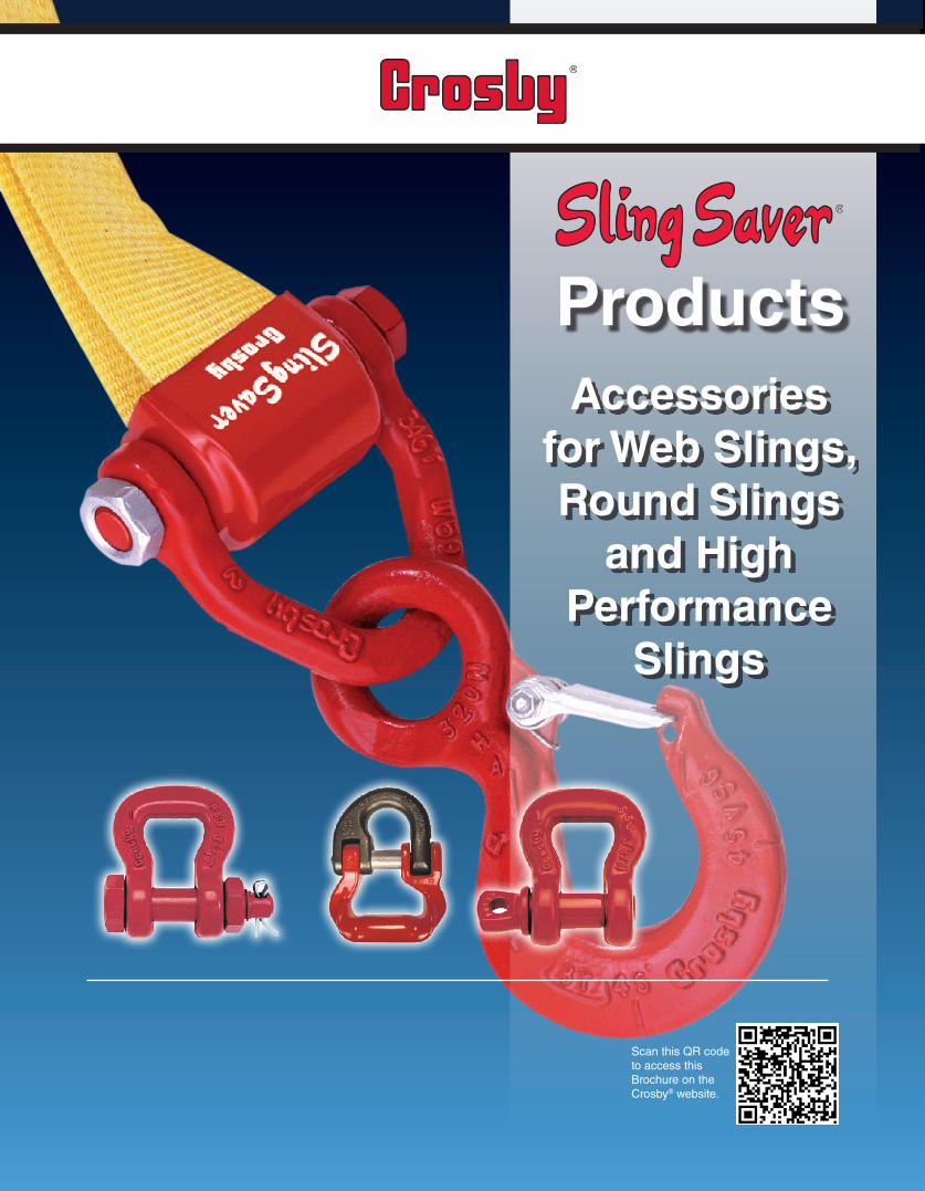
ProductsAccessories
for Web Slings, Round Slings
and High Performance
Slings
Scan this QR code to access this Brochure on the Crosby® website.
Copyright © 2018 The Crosby Group LLCAll Rights Reserved
Table of Contents
… LIFTING THE WORLD INTO THE FUTURE!
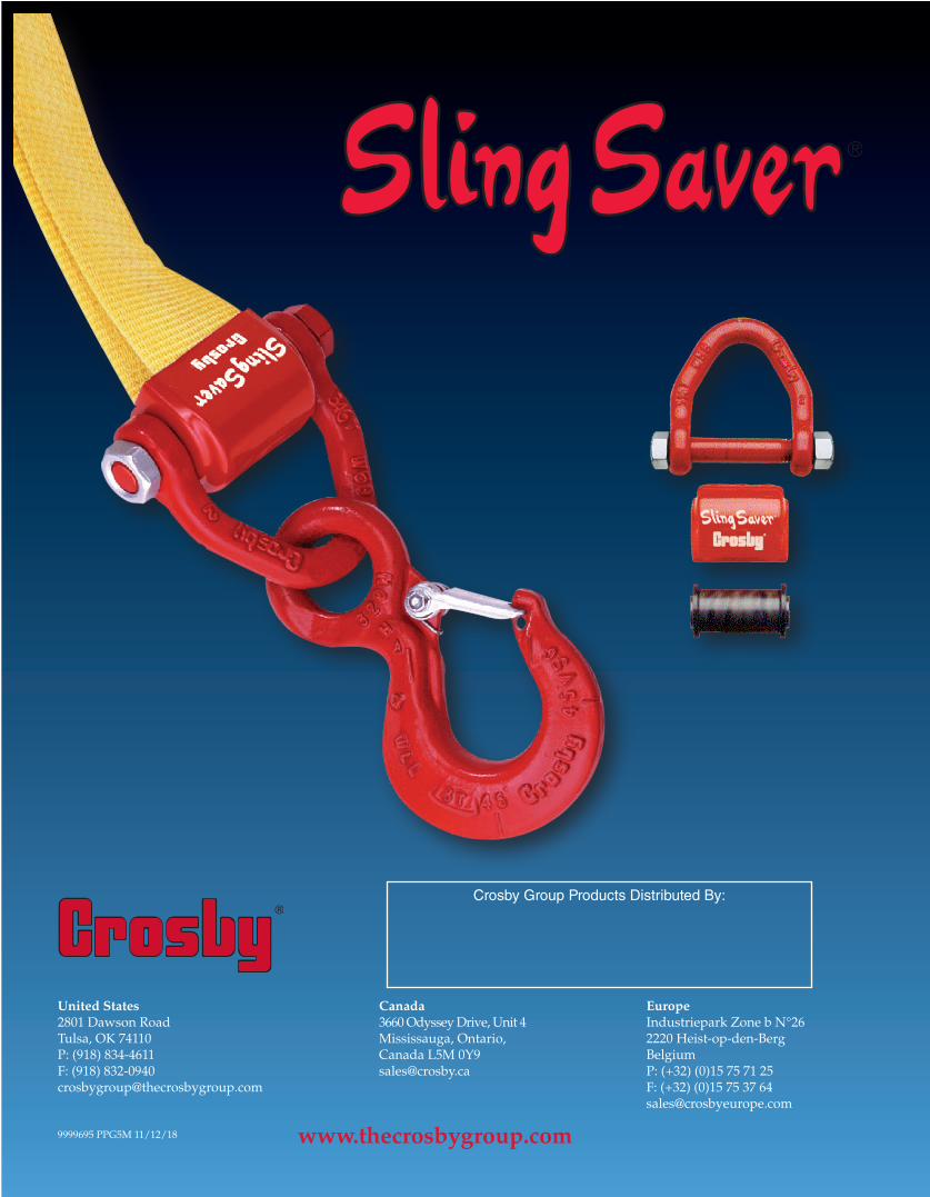
When you’re connecting synthetic slings, either webbing or round sling, to pad eyes, other hardware, chain or to another synthetic sling, Crosby now has the fittings you need.
Crosby’s new Sling Saver® line is the first broad line of fittings developed exclusively for use with synthetic slings. Combined with additional Crosby products currently offered, a complete system has now been developed.
Application Information ............................................................................................................................................................. 1S-280 Web Connector ................................................................................................................................................................... 4S-281 Web Sling Shackle .............................................................................................................................................................. 5S-252 / S-253 ................................................................................................................................................................................. 6S-255 / S-256 ................................................................................................................................................................................. 7WSL-320A ...................................................................................................................................................................................... 8S-282 / S-287 ................................................................................................................................................................................. 9S/G-2160 ...................................................................................................................................................................................... 10A-344 / A-347 ............................................................................................................................................................................. 11S-237 / S-238 High Performance Sling Connector ................................................................................................................ 12Sling Saver® Components ......................................................................................................................................................... 13Web System ................................................................................................................................................................................. 14Synthetic Sling System .............................................................................................................................................................. 15Inspection Information .............................................................................................................................................................. 16Inspection of Fittings ................................................................................................................................................................. 17Inspection of Round Slings ....................................................................................................................................................... 18Inspection of Web Slings ........................................................................................................................................................... 19
Member of
Use your internet-enabled device to scan this code & visit our website.
CANADA3660 Odyssey Drive, Unit 4 Mississauga, Ontario,Canada L5M 0Y9 P: (877) 462-7672F: (877) [email protected]
U.S.A.2801 Dawson Rd.Tulsa, OK 74110U.S.A.P: (918) 834-4611F: (918) [email protected]
EUROPEIndustriepark Zone B n°262220 Heist-op-den-BergBelgiumP: (+32) (0)15 75 71 25F: (+32) (0)15 75 37 [email protected]
www.thecrosbygrooup.com
Copyright © 2018 The Crosby Group LLCAll Rights Reserved
3
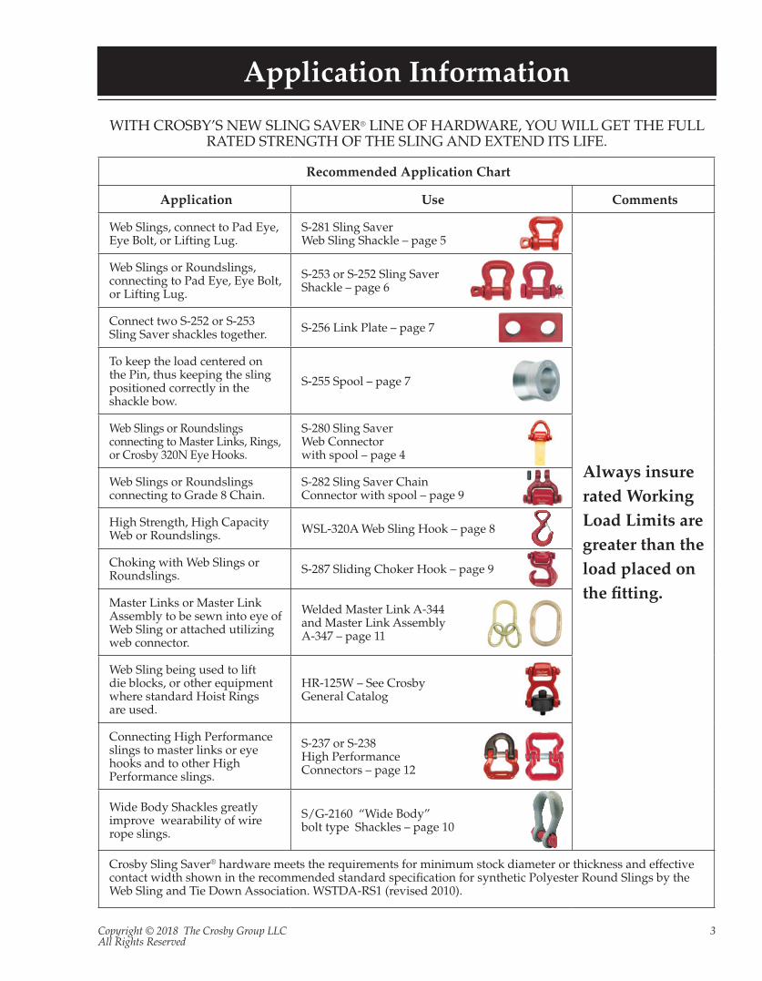
Recommended Application Chart
Application Use Comments
Web Slings, connect to Pad Eye, Eye Bolt, or Lifting Lug.
S-281 Sling Saver Web Sling Shackle – page 5
Always insure rated Working Load Limits are greater than the load placed on the fitting.
Web Slings or Roundslings, connecting to Pad Eye, Eye Bolt, or Lifting Lug.
S-253 or S-252 Sling Saver Shackle – page 6
Connect two S-252 or S-253 Sling Saver shackles together. S-256 Link Plate – page 7
To keep the load centered on the Pin, thus keeping the sling positioned correctly in the shackle bow.
S-255 Spool – page 7
Web Slings or Roundslings connecting to Master Links, Rings, or Crosby 320N Eye Hooks.
S-280 Sling Saver Web Connector with spool – page 4
Web Slings or Roundslings connecting to Grade 8 Chain.
S-282 Sling Saver Chain Connector with spool – page 9
High Strength, High Capacity Web or Roundslings. WSL-320A Web Sling Hook – page 8
Choking with Web Slings or Roundslings. S-287 Sliding Choker Hook – page 9
Master Links or Master Link Assembly to be sewn into eye of Web Sling or attached utilizing web connector.
Welded Master Link A-344 and Master Link Assembly A-347 – page 11
Web Sling being used to lift die blocks, or other equipment where standard Hoist Rings are used.
HR-125W – See CrosbyGeneral Catalog
Connecting High Performance slings to master links or eye hooks and to other High Performance slings.
S-237 or S-238 High Performance Connectors – page 12
Wide Body Shackles greatly improve wearability of wire rope slings.
S/G-2160 “Wide Body” bolt type Shackles – page 10
Crosby Sling Saver® hardware meets the requirements for minimum stock diameter or thickness and effective contact width shown in the recommended standard specification for synthetic Polyester Round Slings by the Web Sling and Tie Down Association. WSTDA-RS1 (revised 2010).
Application Information
WITH CROSBY’S NEW SLING SAVER® LINE OF HARDWARE, YOU WILL GET THE FULL RATED STRENGTH OF THE SLING AND EXTEND ITS LIFE.

Copyright © 2018 The Crosby Group LLCAll Rights Reserved
4
Sling Saver® Web Connector
RoundSlingSize(No.)
WebSlings*
WorkingLoadLimit
(Tons)†S-280
Stock No.
WeightEach(lbs.)
Dimensions(in.)
WebbingWidth(in.)
EyeWidth(in.) Ply A B C D E F G H I J
1 & 2 2 2 2 3-1/4 1021681 1.5 .75 .62 1.63 2.44 .63 .62 2.69 .56 1.19 2.02
3 3 1.5 2 4-1/2 1021690 1.9 .75 .69 1.10 2.01 .75 .69 2.19 .60 1.38 2.34
4 4 2 2 6-1/4 1021700 2.9 .75 .81 1.66 2.56 .88 .75 2.69 .69 1.62 2.46
5 & 6 6 3 2 8-1/2 1021709 5.1 1.00 .94 2.47 3.50 1.00 .88 3.69 .88 1.88 2.84
S-280 Web Connector
* Designed for use with Type III, (Eye & Eye), Class 7, 2 Ply web slings. For 3” and larger webbing width, tapered eye is required.† Maximum Proof Load is 2-1/2 times the Working Load Limit. Minimum Ultimate strength is 5 times the Working Load Limit.
Crosby Sling Saver® hardware meets the requirements for minimum stock diameter or thickness, and effective contact width shown in the Recommended Standards Specification for Synthetic Polyester Round Slings by the Web Sling & Tie Down Association. WSTDA-RS1 (revised 2010)
S-280• All Alloy construction.• Durable vinyl cover that:
• Protects sling at eye • Keeps sling positioned correctly on spool.
• Design Factor of 5 to 1.• Connects Synthetic Web and Synthetic Round Slings to conventional
Crosby hardware including: • 320N Eye Hook • Additional Crosby Grade 8 Fittings • Master Links • Rings • Shackles
• Makes a field assembled bridle quick and easy.• No cotter pin to snag sling material.• Increased radius of spool gives wider sling bearing surface resulting in
an increased area for load distribution, thus: • Increasing Synthetic Sling efficiency as compared to standard anchor
and chain shackle bows and conventional eye hooks. This allows 100% of the slings rated Working Load Limit to be achieved.
• Allowing better load distribution on internal fibers. • Replacement kit for spool and web cover available.• Designed for use with Type III (Eye & Eye), Class 7, 2 ply webbing &
Synthetic Round Slings. Also accomodates single ply and endless slings.
Copyright © 2018 The Crosby Group LLCAll Rights Reserved
5
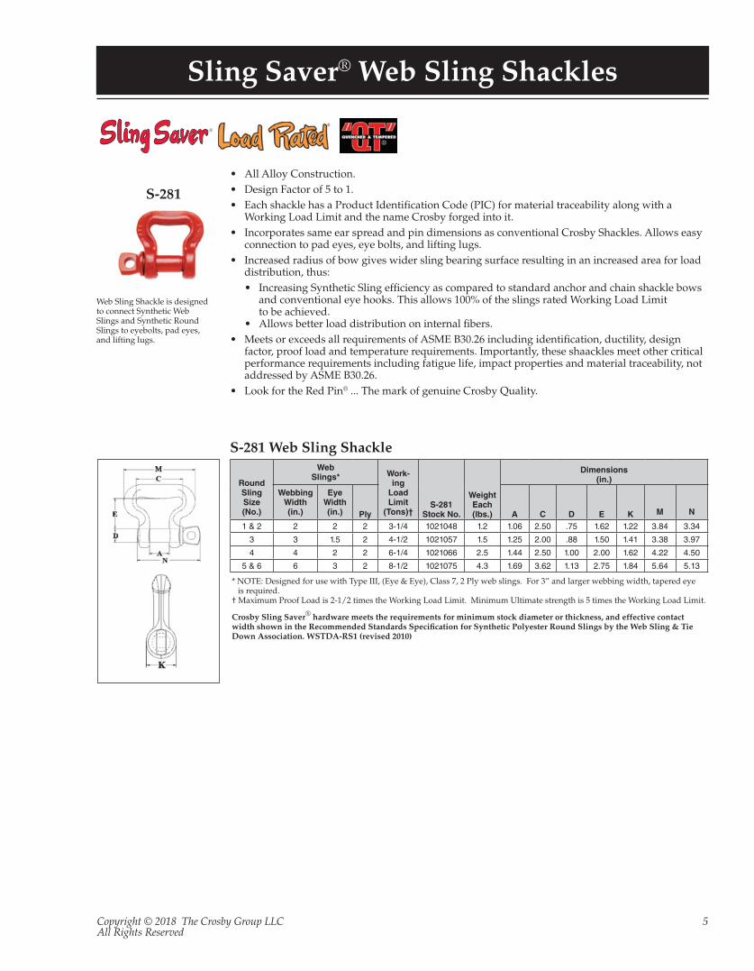
Sling Saver® Web Sling Shackles
RoundSlingSize(No.)
WebSlings* Work-
ingLoadLimit
(Tons)†S-281
Stock No.
WeightEach(lbs.)
Dimensions(in.)
WebbingWidth(in.)
EyeWidth(in.) Ply A C D E K M N
1 & 2 2 2 2 3-1/4 1021048 1.2 1.06 2.50 .75 1.62 1.22 3.84 3.34
3 3 1.5 2 4-1/2 1021057 1.5 1.25 2.00 .88 1.50 1.41 3.38 3.97
4 4 2 2 6-1/4 1021066 2.5 1.44 2.50 1.00 2.00 1.62 4.22 4.50
5 & 6 6 3 2 8-1/2 1021075 4.3 1.69 3.62 1.13 2.75 1.84 5.64 5.13
S-281 Web Sling Shackle
* NOTE: Designed for use with Type III, (Eye & Eye), Class 7, 2 Ply web slings. For 3” and larger webbing width, tapered eye is required.
† Maximum Proof Load is 2-1/2 times the Working Load Limit. Minimum Ultimate strength is 5 times the Working Load Limit.
Crosby Sling Saver® hardware meets the requirements for minimum stock diameter or thickness, and effective contact width shown in the Recommended Standards Specification for Synthetic Polyester Round Slings by the Web Sling & Tie Down Association. WSTDA-RS1 (revised 2010)
S-281
• All Alloy Construction.• Design Factor of 5 to 1.• Each shackle has a Product Identification Code (PIC) for material traceability along with a
Working Load Limit and the name Crosby forged into it.• Incorporates same ear spread and pin dimensions as conventional Crosby Shackles. Allows easy
connection to pad eyes, eye bolts, and lifting lugs.• Increased radius of bow gives wider sling bearing surface resulting in an increased area for load
distribution, thus:• Increasing Synthetic Sling efficiency as compared to standard anchor and chain shackle bows
and conventional eye hooks. This allows 100% of the slings rated Working Load Limit to be achieved.
• Allows better load distribution on internal fibers.• Meets or exceeds all requirements of ASME B30.26 including identification, ductility, design
factor, proof load and temperature requirements. Importantly, these shaackles meet other critical performance requirements including fatigue life, impact properties and material traceability, not addressed by ASME B30.26.
• Look for the Red Pin® ... The mark of genuine Crosby Quality.
Web Sling Shackle is designed to connect Synthetic Web Slings and Synthetic Round Slings to eyebolts, pad eyes, and lifting lugs.
Copyright © 2018 The Crosby Group LLCAll Rights Reserved
6
Sling Saver® Web Sling Shackles
®
M
C
E
D
BF
G
A
L
H
J
K
M
C
E
D
B
P
G
A
L
N
RK
WebSlingEye
Width(in.)
RoundSlingSize(No.)
WorkingLoadLimit(t)*
S-252StockNo.
WeightEach(lbs.)
Dimensions(in.)
A B C D E F G H J K L M
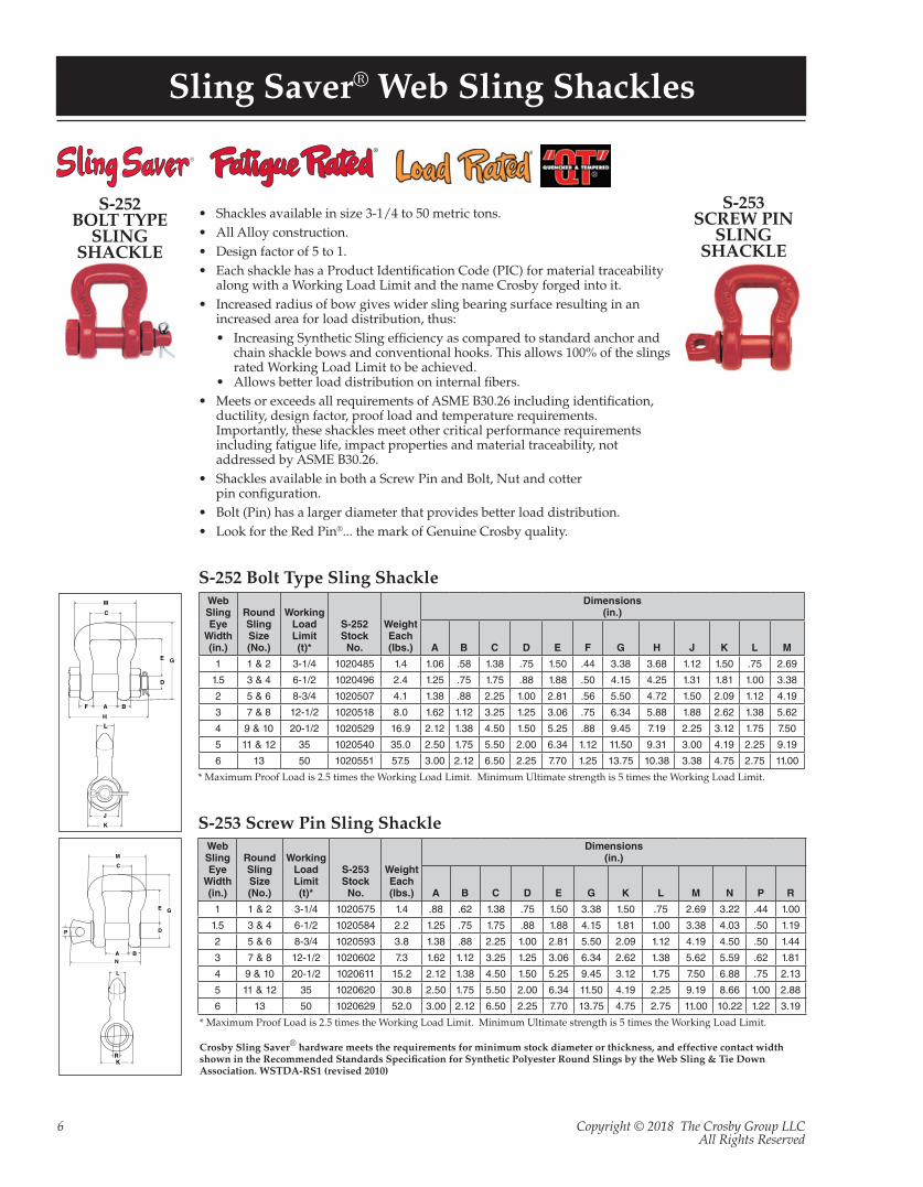
1 1 & 2 3-1/4 1020485 1.4 1.06 .58 1.38 .75 1.50 .44 3.38 3.68 1.12 1.50 .75 2.69
1.5 3 & 4 6-1/2 1020496 2.4 1.25 .75 1.75 .88 1.88 .50 4.15 4.25 1.31 1.81 1.00 3.38
2 5 & 6 8-3/4 1020507 4.1 1.38 .88 2.25 1.00 2.81 .56 5.50 4.72 1.50 2.09 1.12 4.19
3 7 & 8 12-1/2 1020518 8.0 1.62 1.12 3.25 1.25 3.06 .75 6.34 5.88 1.88 2.62 1.38 5.62
4 9 & 10 20-1/2 1020529 16.9 2.12 1.38 4.50 1.50 5.25 .88 9.45 7.19 2.25 3.12 1.75 7.50
5 11 & 12 35 1020540 35.0 2.50 1.75 5.50 2.00 6.34 1.12 11.50 9.31 3.00 4.19 2.25 9.19
6 13 50 1020551 57.5 3.00 2.12 6.50 2.25 7.70 1.25 13.75 10.38 3.38 4.75 2.75 11.00
WebSlingEye
Width(in.)
RoundSlingSize(No.)
WorkingLoadLimit(t)*
S-253StockNo.
WeightEach(lbs.)
Dimensions(in.)
A B C D E G K L M N P R
1 1 & 2 3-1/4 1020575 1.4 .88 .62 1.38 .75 1.50 3.38 1.50 .75 2.69 3.22 .44 1.00
1.5 3 & 4 6-1/2 1020584 2.2 1.25 .75 1.75 .88 1.88 4.15 1.81 1.00 3.38 4.03 .50 1.19
2 5 & 6 8-3/4 1020593 3.8 1.38 .88 2.25 1.00 2.81 5.50 2.09 1.12 4.19 4.50 .50 1.44
3 7 & 8 12-1/2 1020602 7.3 1.62 1.12 3.25 1.25 3.06 6.34 2.62 1.38 5.62 5.59 .62 1.81
4 9 & 10 20-1/2 1020611 15.2 2.12 1.38 4.50 1.50 5.25 9.45 3.12 1.75 7.50 6.88 .75 2.13
5 11 & 12 35 1020620 30.8 2.50 1.75 5.50 2.00 6.34 11.50 4.19 2.25 9.19 8.66 1.00 2.88
6 13 50 1020629 52.0 3.00 2.12 6.50 2.25 7.70 13.75 4.75 2.75 11.00 10.22 1.22 3.19
S-252 Bolt Type Sling Shackle
S-253 Screw Pin Sling Shackle
* Maximum Proof Load is 2.5 times the Working Load Limit. Minimum Ultimate strength is 5 times the Working Load Limit.
* Maximum Proof Load is 2.5 times the Working Load Limit. Minimum Ultimate strength is 5 times the Working Load Limit.
Crosby Sling Saver® hardware meets the requirements for minimum stock diameter or thickness, and effective contact width shown in the Recommended Standards Specification for Synthetic Polyester Round Slings by the Web Sling & Tie Down Association. WSTDA-RS1 (revised 2010)
S-252BOLT TYPE
SLING SHACKLE
S-253SCREW PIN
SLING SHACKLE
• Shackles available in size 3-1/4 to 50 metric tons.• All Alloy construction.• Design factor of 5 to 1.• Each shackle has a Product Identification Code (PIC) for material traceability
along with a Working Load Limit and the name Crosby forged into it.• Increased radius of bow gives wider sling bearing surface resulting in an
increased area for load distribution, thus: • Increasing Synthetic Sling efficiency as compared to standard anchor and
chain shackle bows and conventional hooks. This allows 100% of the slings rated Working Load Limit to be achieved.
• Allows better load distribution on internal fibers.• Meets or exceeds all requirements of ASME B30.26 including identification,
ductility, design factor, proof load and temperature requirements. Importantly, these shackles meet other critical performance requirements including fatigue life, impact properties and material traceability, not addressed by ASME B30.26.
• Shackles available in both a Screw Pin and Bolt, Nut and cotter pin configuration.
• Bolt (Pin) has a larger diameter that provides better load distribution.• Look for the Red Pin®... the mark of Genuine Crosby quality.
Copyright © 2018 The Crosby Group LLCAll Rights Reserved
7
Sling Saver® Shackle Accessories
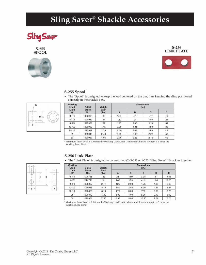
S-255 Spool• The “Spool” is designed to keep the load centered on the pin, thus keeping the sling positioned
correctly in the shackle bow.
S-256 Link Plate• The “Link Plate” is designed to connect two (2) S-252 or S-253 “Sling Saver®” Shackles together.
* Maximum Proof Load is 2.5 times the Working Load Limit. Minimum Ultimate strength is 5 times the Working Load Limit.
* Maximum Proof Load is 2.5 times the Working Load Limit. Minimum Ultimate strength is 5 times the Working Load Limit.
S-255SPOOL
S-256LINK PLATE
WorkingLoadLimit(t)*
S-255StockNo.
WeightEach(lbs.)
Dimensions(in.)
A B C D
3-1/4 1020903 .33 1.25 .81 .75 .19
6-1/2 1020912 .57 1.50 .94 1.00 .25
8-3/4 1020921 .89 1.75 1.05 1.19 .31
12-1/2 1020930 1.45 2.00 1.31 1.50 .38
20-1/2 1020939 2.79 2.50 1.63 1.88 .44
35 1020948 2.40 3.25 2.13 2.25 .50
50 1020957 4.06 3.75 2.38 2.75 .62
WorkingLoadLimit(t)*
S-256StockNo.
WeightEach(lbs.)
Dimensions(in.)
A B C D E
3-1/4 1020785 .83 .75 1.50 3.38 .81 1.88
6-1/2 1020796 1.62 1.00 1.75 4.12 .94 2.25
8-3/4 1020807 2.71 1.25 2.00 4.75 1.06 2.62
12-1/2 1020818 5.18 1.50 2.50 6.00 1.31 3.37
20-1/2 1020829 8.19 1.75 3.00 7.00 1.62 3.75
35 1020840 17.19 2.00 4.00 9.25 2.12 5.00
50 1020851 37.40 2.88 5.00 10.50 2.38 5.75
Copyright © 2018 The Crosby Group LLCAll Rights Reserved
8
Sling Saver® Synthetic Sling Hooks
®
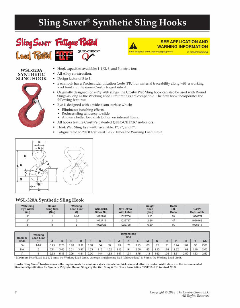
WSL-320A Synthetic Sling Hook
* Maximum Proof Load is 2-1/2 times the Working Load Limit. Average straightening load (ultimate load) is 5 times the Working Load Limit.
Crosby Sling Saver® hardware meets the requirements for minimum stock diameter or thickness, and effective contact width shown in the Recommended Standards Specification for Synthetic Polyester Round Slings by the Web Sling & Tie Down Association. WSTDA-RS1 (revised 2010)
WSL-320ASYNTHETIC
SLING HOOK
• Hook capacities available: 1-1/2, 3, and 5 metric tons.• All Alloy construction.• Design factor of 5 to 1.• Each hook has a Product Identification Code (PIC) for material traceability along with a working
load limit and the name Crosby forged into it.• Originally designed for 2-Ply Web slings, the Crosby Web Sling hook can also be used with Round
Slings as long as the Working Load Limit ratings are compatible. The new hook incorporates the following features:
• Eye is designed with a wide beam surface which: • Eliminates bunching effects. • Reduces sling tendency to slide. • Allows a better load distribution on internal fibers.
• All hooks feature Crosby’s patented QUIC-CHECK® indicators. • Hook Web Sling Eye width available: 1”, 2”, and 3”.• Fatigue rated to 20,000 cycles at 1-1/2 times the Working Load Limit.
SEE APPLICATION ANDWARNING INFORMATION
Para Español: www.thecrosbygroup.com in General Catalog
Web SlingEye Width
(in.)
RoundSling Size
(No.)
WorkingLoad Limit
(t)WSL-320AStock No.
WSL-320Awith Latch
WeightEach(lbs.)
HookI.D.
CodeS-4320
Rep. Latch
1” 1 1-1/2 1022701 1022706 1.10 FA 1096374
2” 2 3 1022712 1022717 2.86 HA 1096468
3” 3 5 1022723 1022728 6.60 IA 1096515
Hook ID Code
WorkingLoad Limit
(t)*
Dimensions(in.)
A B C D F G H J K L M N O P Q T AA
FA 1-1/2 5.25 2.26 3.98 3.11 1.38 .84 .94 .93 .71 1.50 .63 .75 .91 2.24 1.01 .98 2.00
HA 3 7.11 3.66 5.31 3.97 1.63 1.13 1.32 1.13 .94 2.50 .85 1.13 1.09 2.82 1.69 1.16 2.00
IA 5 9.33 5.13 7.06 4.81 2.00 1.44 1.63 1.47 1.31 3.75 1.13 1.63 1.36 3.51 2.59 1.53 2.50

Copyright © 2018 The Crosby Group LLCAll Rights Reserved
9
Sling Saver® Fittings / Accessories
S-282WEB / CHAINCONNECTOR
• Available in three sizes:• 3-1/4 ton Working Load Limit -2” Webbing to 3/8” (10mm) chain. • 4-1/2 ton Working Load Limit - 1-1/2” (3” Tapered Webbing) to 1/2” (13mm) chain. • 6-1/4 ton Working Load Limit - 2” (4” Tapered Webbing) to 5/8” (16mm) chain.
• Alloy Steel (Quenched and Tempered).• Each Connector has a Product Identification Code (PIC) for material traceability along with a
Working Load Limit and the name Crosby forged into it.• Uses same spool and cover as S-280 Web Connector.
• Replacement Kit for Spool and Web Cover available.
S-287CHOKER
HOOK
Designed around the same concept as our S-280 Web
Connector, the S-282 Chain Connector makes the
connection from your web sling to existing chain quick
and easy.
S-282 Web / Chain Connector
RoundSlingSize(No.)
WebSlings*
ChainSize
WorkingLoadLimit
(Tons) †
S-282StockNo.
WeightEach(lbs.)
Dimensions(in.)
WebbingWidth(in.)
EyeWidth(in.) Ply B C E F
1 & 2 2 2 2 3/8 3-1/4 1021084 1.9 4.33 2.13 2.11 4.77
3 3 1.5 2 1/2 4-1/2 1021093 2.8 5.04 1.63 2.44 4.54
4 4 2 2 5/8 6-1/4 1021100 4.3 5.69 2.13 2.54 5.31
* NOTE: Designed for use with Type III, (Eye & Eye), Class 7, 2 Ply web slings.† Maximum Proof Load is 2-1/2 times the Working Load Limit. Minimum Ultimate Strength is 5 times the Working Load Limit.
• Available in 2 sizes: 3-1/4 tons (2” webbing) and 4-1/2 tons (3” webbing)• Forged Alloy steel – Quenched & Tempered• Design factor of 5 to 1.• Each Connector has a Product Identification Code (PIC) for material traceability along with a
Working Load Limit and the name Crosby forged into it.• Special design of hook protects the synthetic sling when dropped or dragged.• Designed to reduce friction, abrasion, and fraying in choker area.• Uses same spool and cover as S-280 Web Connector.
• Replacement Kit for Spool and Web Cover available.
RoundSlingSize(No.)
WebSlings* Working
LoadLimit
(Tons) †
S-287StockNo.
WeightEach(lbs.)
Dimensions(in.)
WebbingWidth(in.)
EyeWidth(in.) Ply A B C D E F G H J AA
1 & 2 2 2 2 3-1/4 1021909 3.7 2.13 2.50 3.32 .38 6.03 4.77 4.88 .34 1.50 1.50
3 3 1.5 2 4-1/2 1021918 6.1 1.63 3.50 3.67 .38 7.06 4.53 6.51 1.36 1.88 –
* NOTE: Designed for use with Type III, (Eye & Eye), Class 7, 2 Ply web slings.† Maximum Proof Load is 2-1/2 times the Working Load Limit. Average straightening load (ultimate load) is 5 times the Working Load Limit.
Crosby Sling Saver® hardware meets the requirements for minimum stock diameter or thickness, and effective contact width shown in the Recommended Standards Specification for Synthetic Polyester Round Slings by the Web Sling & Tie Down Association. WSTDA-RS1 (revised 2010)
S-287 Sliding Choker Hook
Copyright © 2018 The Crosby Group LLCAll Rights Reserved
10
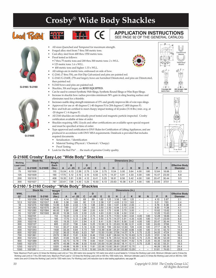
• All sizes Quenched and Tempered for maximum strength.• Forged alloy steel from 7 thru 300 metric tons. • Cast alloy steel from 400 thru 1550 metric tons.• Proof tested as follows:
• 7 thru 75 metric tons and 200 thru 300 metric tons: 2 x WLL. • 125 metric tons: 1.6 x WLL. • 400 metric tons and higher: 1.33 x WLL.
• All ratings are in metric tons, embossed on side of bow. • G-2160, (7 thru 55t), are Hot Dip Galvanized and pins are painted red.• G-2160/G-2160E, (75t and larger), bows are furnished Dimetcoted, and pins are Dimetcoted,
then painted red.• S-2160 bows and pins are painted red.• Shackles, 30t and larger, are RFID EQUIPPED.• Can be used to connect Synthetic Web Slings, Synthetic Round Slings or Wire Rope Slings. • Increase in shackle bow radius provides minimum 58% gain in sling bearing surface and
eliminates need for a thimble. • Increases usable sling strength minimum of 15% and greatly improves life of wire rope slings. • Approved for use at -40 degrees C (-40 degrees F) to 204 degrees C (400 degrees F).• Bow and bolt are certified to meet charpy impact testing of 42 joules (31 ft-lbs.) min. avg. at
-20 degree C (-4 degree F).• All 2160 shackles are individually proof tested and magnetic particle inspected. Crosby
certification available at time of order.• Shackles requiring ABS, Lloyds and other certifications are available upon special request
and must be specified at time of order.• Type approved and certification to DNV Rules for Certification of Lifting Appliances, and are
produced in accordance with DNV MSA requirements. Databook is provided that includes required documents.• Serialization / Identification • Material Testing (Physical / Chemical / Charpy) • Proof Testing
• Look for the Red Pin® . . . the mark of genuine Crosby quality.
Crosby® Wide Body ShacklesAPPLICATION INSTRUCTIONSSEE PAGE 92 OF THE GENERAL CATALOG
G-2160 / S-2160 Crosby® “Wide Body” Shackles
WWL(t)*
Stock No. WeightEach(lbs.)
Dimensions (in.)
G-2160 S-2160 AB
+/- .25 CD
+/- .02 E G H J K M N P REffective Body
Diameter7 1021256 1021548 4.0 4.14 1.25 .69 .88 1.82 1.25 3.56 1.60 1.25 – – 4.10 5.87 2.1
12.5 1021265 1021557 8.80 5.38 1.69 .92 1.13 2.38 1.37 4.63 2.13 1.63 – – 5.51 7.63 2.418 1021274 1021566 14.90 6.69 2.03 1.16 1.38 2.69 1.50 5.81 2.50 2.00 – – 6.76 9.38 2.830 1021283 1021575 26.50 7.69 2.37 1.38 1.63 3.50 2.50 6.94 3.13 2.50 – – 8.50 11.38 4.140 1021285 1021584 46.00 9.28 2.88 1.69 2.00 4.00 1.75 8.06 3.75 3.00 – – 10.62 13.62 3.655 1021287 1021593 68.00 10.36 3.25 2.00 2.25 4.63 2.00 9.36 4.50 3.50 – – 12.26 15.63 4.375 1022101 – 112 15.04 4.13 2.12 2.75 5.34 3.75 11.53 5.00 3.64 4.00 1.80 12.28 18.66 6.3125 1022110 – 193 17.70 5.12 2.66 3.15 6.50 3.75 14.37 5.91 4.33 4.00 1.80 15.47 23.00 6.8200 1022118 – 420 19.35 5.91 2.94 4.12 8.41 5.25 18.91 8.56 5.42 4.00 1.80 20.47 30.44 9.5300 1022127 – 805 22.61 7.38 3.84 5.25 10.50 6.13 23.63 10.38 6.31 4.00 1.80 24.00 37.66 11.4400 1021334 – 1143 30.27 8.66 5.16 6.30 12.56 7.99 22.64 12.60 7.28 4.00 1.80 27.17 38.78 14.3500 1021343 – 1439 33.35 9.84 5.73 7.09 13.39 8.09 24.81 13.39 8.86 4.00 1.80 31.10 42.72 14.8600 1021352 – 2132 36.02 10.83 6.23 7.87 15.50 13.00 27.56 14.57 9.74 5.75 2.25 34.05 47.24 20.3700 1021361 – 2579 38.91 11.81 6.59 8.46 17.03 8.87 28.94 15.75 10.63 5.75 2.25 37.01 50.18 16.6800 1021254 – 3025 41.66 12.80 7.30 9.06 17.69 9.76 29.53 16.54 10.92 5.75 2.25 38.39 52.09 18.0900 1021389 – 3678 43.73 13.78 7.78 9.84 18.81 13.00 29.82 18.81 11.52 5.75 2.25 40.35 54.59 22.41000 1021370 – 4079 45.98 14.96 8.33 10.63 20.00 10.26 29.92 18.11 12.11 5.75 2.25 42.32 55.31 19.31250 1021272 – 5320 49.86 16.99 9.16 11.81 22.56 13.92 36.61 20.87 12.70 – – 46.26 65.35 24.41550 1021281 – 8302 54.89 18.31 11.10 12.60 24.25 12.52 42.32 22.82 13.29 – – 51.81 74.63 23.9
*Note: Maximum Proof Load is 2.0 times the Working Load Limit on 7 thru 300 metric tons (except for 125 metric tons which is proof tested to 1.6 times the Working Load Limit). Minimum Ultimate Load is 5 times the Working Load Limit on 7 thru 300 metric tons. Maximum Proof Load is 1.33 times the Working Load Limit on 400 thru 1550 metric tons. Minimum Ultimate Load is 4.5 times the Working Load Limit on 400 thru 1250 metric tons and 4.5 times the Working Load Limit for 1550 metric tons. For Working Load Limit reduction due to side loading applications, see page 94.
G-2160E
G-2160 / S-2160
G-2160E Crosby® Easy-Loc “Wide Body” ShacklesWorking
Load Limit(t)*
Stock No.WeightEach(lbs.)
Dimensions (in.)
G-2160E S-2160E AB
+/- .25 CD
+/- .02 E G H J K M N P REffective Body
Diameter75 1021500 – 110 15.04 4.13 2.39 2.75 5.34 3.75 11.54 5.00 3.64 4.00 1.80 12.64 18.66 6.3125 1021509 – 190 17.70 5.12 3.10 3.15 6.50 3.75 14.37 5.91 4.33 4.00 1.80 15.47 23.00 6.8200 1021518 – 408 19.35 5.91 3.39 4.12 8.41 5.25 18.91 8.56 5.42 4.00 1.80 20.47 30.44 9.5300 1021527 – 787 22.61 7.38 4.30 5.25 10.50 6.13 23.63 10.38 6.31 4.00 1.80 23.93 37.51 11.4
J
R H
D
C A
B
M
E
P K G
N
J
R H
D
C A
B
M
E
P K G
N
Copyright © 2018 The Crosby Group LLCAll Rights Reserved
11
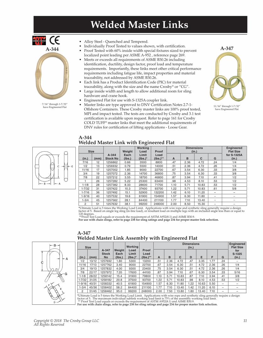
Welded Master Links
A-344
• Alloy Steel - Quenched and Tempered.• Individually Proof Tested to values shown, with certification.• Proof Tested with 60% inside width special fixtures sized to prevent
localized point leading per ASME A-952 , reference page 269.• Meets or exceeds all requirements of ASME B30.26 including
identification, ductility, design factor, proof load and temperature requirements. Importantly, these links meet other critical performance requirements including fatigue life, impact properties and material traceability, not addressed by ASME B30.26.
• Each link has a Product Identification Code (PIC) for material traceability, along with the size and the name Crosby® or “CG”.
• Large inside width and length to allow additional room for sling hardware and crane hook.
• Engineered Flat for use with S-1325A coupler link.• Master links are type approved to DNV Certification Notes 2.7-1-
Offshore Containers. These Crosby master links are 100% proof tested, MPI and impact tested. The tests are conducted by Crosby and 3.1 test certification is available upon request. Refer to page 161 for Crosby COLD TUFF® master links that meet the additional requirements of DNV rules for certification of lifting applications - Loose Gear.
SizeA-344
Stock No
WeightEach(lbs.)
WorkingLoad Limit(lbs.)*
ProofLoad
(lbs.)**
Dimensions(in.)
EngineeredFlat Size
for S-1325A(in.)(in.) (mm) A B C G
7/16 12 1256862 0.66 3500 8800 .47 2.36 4.72 .24 1/41/2 13 1256932 0.79 5500 14000 .51 2.36 4.72 .26 1/4
11/16 17 1257002 1.85 9000 22700 .67 3.54 6.30 .33 3/83/4 19 1257072 2.36 14700 36800 .75 3.54 6.30 .33 3/87/8 22 1257212 3.55 18700 46800 .87 3.94 7.10 .41 1/21 26 1257282 5.22 25300 63400 .98 4.53 8.10 .53 1/2
1-1/8 28 1257382 8.33 28600 71700 1.10 5.71 10.83 .53 1/21-7/32 31 1257422 10.3 37400 93700 1.22 5.71 10.83 .61 5/81-7/16 36 1257492 15.1 52900 132200 1.42 6.10 11.20 – –1-9/16 40 1257532 19.6 61900 154900 1.57 6.30 11.80 – –1-3/4 45 1257562 28.1 84400 211100 1.77 7.10 13.40 – –
2 51 1257632 38.1 99200 248000 2.00 8.50 15.30 – –
A-344Welded Master Link with Engineered Flat
A-347
SizeA-347Stock
No
WeightEach(lbs.)
WorkingLoad Limit(lbs.)*
ProofLoad
(lbs.)**
Dimensions(in.)
EngineeredFlat Size
forS-1325
(in.)(in.) (mm) A B C D E F G1/2 13/12 1257692 1.80 5300 13200 .51 2.36 4.72 .47 3.35 1.77 .24 –
11/16 17/13 1257762 3.40 9000 22700 .67 3.54 6.30 .51 4.72 2.36 .26 1/43/4 19/13 1257832 4.00 9300 23400 .75 3.54 6.30 .51 4.72 2.36 .26 1/47/8 22/17 1257972 7.20 17600 44100 .87 3.94 7.10 .67 6.30 3.54 .33 5/16
1-1/8 28/22 1258142 15.4 31900 79800 1.10 5.71 10.83 .87 7.10 3.94 .41 3/81-7/32 31/25 1258182 20.8 37500 93700 1.22 5.71 10.83 .98 8.10 4.53 .53 1/21-9/16 40/31 1258332 40.5 61900 154900 1.57 6.30 11.80 1.22 10.63 5.50 – –1-3/4 45/36 1258402 58.2 84400 211100 1.77 7.10 13.40 1.42 11.20 6.10 – –
2 51/45 1258462 95.0 99200 248000 2.00 7.50 13.80 1.80 13.40 7.10 – –
A-347Welded Master Link Assembly with Engineered Flat
*Ultimate Load is 5 times the Working Load Limit. Applications with wire rope and synthetic sling generally require a design factor of 5. Based on single leg sling (in-line load), or resultant load on multiple legs with an included angle less than or equal to 120 degrees. **Proof Test Load equals or exceeds the requirement of ASTM A952(8.1) and ASME B30.9.For use with chain slings, refer to page 238 for sling ratings and page 234 for proper master link selection.
*Ultimate Load is 5 times the Working Load Limit. Applications with wire rope and synthetic sling generally require a design factor of 5. The maximum individual sublink working load limit is 75% of the assembly working load limit. ** Proof Test Load equals or exceeds the requirement of ASTM A952(8.1) and ASME B30.9.For use with chain slings, refer to page 238 for sling ratings and page 234 for proper master link selection.
7/16” through 1-7/32” have Engineered Flat 11/16” through 1-7/32”
have Engineered Flat
Copyright © 2018 The Crosby Group LLCAll Rights Reserved
12
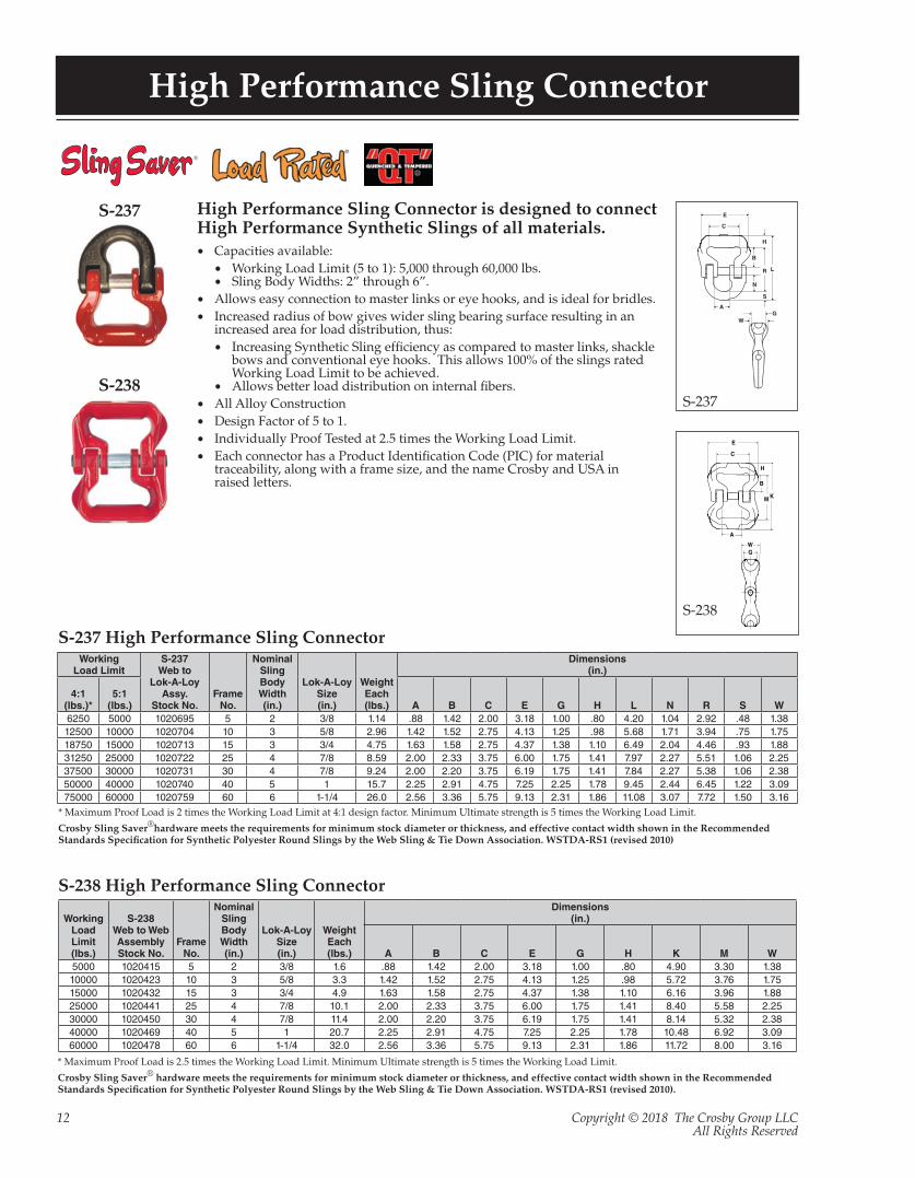
High Performance Sling Connector
S-237
S-238
High Performance Sling Connector is designed to connect High Performance Synthetic Slings of all materials.• Capacities available:
• Working Load Limit (5 to 1): 5,000 through 60,000 lbs.• Sling Body Widths: 2” through 6”.
• Allows easy connection to master links or eye hooks, and is ideal for bridles.• Increased radius of bow gives wider sling bearing surface resulting in an
increased area for load distribution, thus:• Increasing Synthetic Sling efficiency as compared to master links, shackle
bows and conventional eye hooks. This allows 100% of the slings rated Working Load Limit to be achieved.
• Allows better load distribution on internal fibers. • All Alloy Construction• Design Factor of 5 to 1.• Individually Proof Tested at 2.5 times the Working Load Limit.• Each connector has a Product Identification Code (PIC) for material
traceability, along with a frame size, and the name Crosby and USA in raised letters.
* Maximum Proof Load is 2 times the Working Load Limit at 4:1 design factor. Minimum Ultimate strength is 5 times the Working Load Limit.
Crosby Sling Saver®hardware meets the requirements for minimum stock diameter or thickness, and effective contact width shown in the Recommended Standards Specification for Synthetic Polyester Round Slings by the Web Sling & Tie Down Association. WSTDA-RS1 (revised 2010)
* Maximum Proof Load is 2.5 times the Working Load Limit. Minimum Ultimate strength is 5 times the Working Load Limit.
Crosby Sling Saver® hardware meets the requirements for minimum stock diameter or thickness, and effective contact width shown in the Recommended Standards Specification for Synthetic Polyester Round Slings by the Web Sling & Tie Down Association. WSTDA-RS1 (revised 2010).
E
C
B
L
H
S
N
A
R
WG
S-237
WorkingLoad Limit
S-237Web to
Lok-A-LoyAssy.
Stock No.Frame
No.
NominalSlingBodyWidth(in.)
Lok-A-LoySize(in.)
WeightEach(lbs.)
Dimensions(in.)
4:1(lbs.)*
5:1(lbs.) A B C E G H L N R S W
6250 5000 1020695 5 2 3/8 1.14 .88 1.42 2.00 3.18 1.00 .80 4.20 1.04 2.92 .48 1.3812500 10000 1020704 10 3 5/8 2.96 1.42 1.52 2.75 4.13 1.25 .98 5.68 1.71 3.94 .75 1.7518750 15000 1020713 15 3 3/4 4.75 1.63 1.58 2.75 4.37 1.38 1.10 6.49 2.04 4.46 .93 1.8831250 25000 1020722 25 4 7/8 8.59 2.00 2.33 3.75 6.00 1.75 1.41 7.97 2.27 5.51 1.06 2.2537500 30000 1020731 30 4 7/8 9.24 2.00 2.20 3.75 6.19 1.75 1.41 7.84 2.27 5.38 1.06 2.3850000 40000 1020740 40 5 1 15.7 2.25 2.91 4.75 7.25 2.25 1.78 9.45 2.44 6.45 1.22 3.0975000 60000 1020759 60 6 1-1/4 26.0 2.56 3.36 5.75 9.13 2.31 1.86 11.08 3.07 7.72 1.50 3.16
S-237 High Performance Sling Connector
S-238 High Performance Sling Connector
Working Load Limit(lbs.)
S-238Web to WebAssemblyStock No.
Frame No.
NominalSlingBodyWidth(in.)
Lok-A-LoySize(in.)
WeightEach(lbs.)
Dimensions(in.)
A B C E G H K M W5000 1020415 5 2 3/8 1.6 .88 1.42 2.00 3.18 1.00 .80 4.90 3.30 1.3810000 1020423 10 3 5/8 3.3 1.42 1.52 2.75 4.13 1.25 .98 5.72 3.76 1.7515000 1020432 15 3 3/4 4.9 1.63 1.58 2.75 4.37 1.38 1.10 6.16 3.96 1.8825000 1020441 25 4 7/8 10.1 2.00 2.33 3.75 6.00 1.75 1.41 8.40 5.58 2.2530000 1020450 30 4 7/8 11.4 2.00 2.20 3.75 6.19 1.75 1.41 8.14 5.32 2.3840000 1020469 40 5 1 20.7 2.25 2.91 4.75 7.25 2.25 1.78 10.48 6.92 3.0960000 1020478 60 6 1-1/4 32.0 2.56 3.36 5.75 9.13 2.31 1.86 11.72 8.00 3.16
E
C
B
H
M
A
WG
K
S-238
Copyright © 2018 The Crosby Group LLCAll Rights Reserved
13
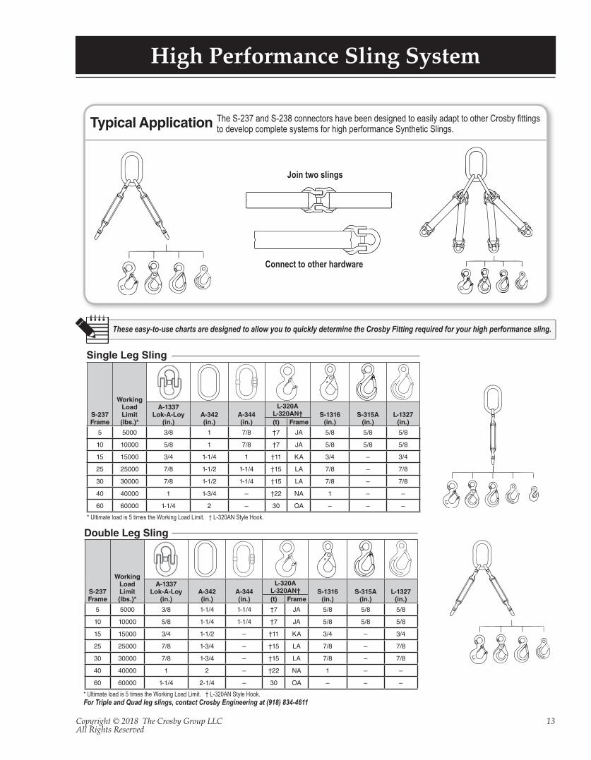
High Performance Sling System
These easy-to-use charts are designed to allow you to quickly determine the Crosby Fitting required for your high performance sling.
Single Leg Sling
Double Leg Sling
* Ultimate load is 5 times the Working Load Limit. † L-320AN Style Hook.
* Ultimate load is 5 times the Working Load Limit. † L-320AN Style Hook.For Triple and Quad leg slings, contact Crosby Engineering at (918) 834-4611
S-237Frame
Working Load Limit(lbs.)*
A-1337Lok-A-Loy
(in.)A-342(in.)
A-344(in.)
L-320AL-320AN† S-1316
(in.)S-315A
(in.)L-1327
(in.)(t) Frame
5 5000 3/8 1 7/8 †7 JA 5/8 5/8 5/8
10 10000 5/8 1 7/8 †7 JA 5/8 5/8 5/8
15 15000 3/4 1-1/4 1 †11 KA 3/4 – 3/4
25 25000 7/8 1-1/2 1-1/4 †15 LA 7/8 – 7/8
30 30000 7/8 1-1/2 1-1/4 †15 LA 7/8 – 7/8
40 40000 1 1-3/4 – †22 NA 1 – –
60 60000 1-1/4 2 – 30 OA – – –
S-237Frame
Working Load Limit(lbs.)*
A-1337Lok-A-Loy
(in.)A-342(in.)
A-344(in.)
L-320AL-320AN† S-1316
(in.)S-315A
(in.)L-1327
(in.)(t) Frame
5 5000 3/8 1-1/4 1-1/4 †7 JA 5/8 5/8 5/8
10 10000 5/8 1-1/4 1-1/4 †7 JA 5/8 5/8 5/8
15 15000 3/4 1-1/2 – †11 KA 3/4 – 3/4
25 25000 7/8 1-3/4 – †15 LA 7/8 – 7/8
30 30000 7/8 1-3/4 – †15 LA 7/8 – 7/8
40 40000 1 2 – †22 NA 1 – –
60 60000 1-1/4 2-1/4 – 30 OA – – –
The S-237 and S-238 connectors have been designed to easily adapt to other Crosby fittings to develop complete systems for high performance Synthetic Slings. Typical Application
Connect to other hardware
Join two slings
Copyright © 2018 The Crosby Group LLCAll Rights Reserved
14
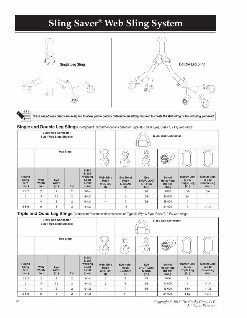
Sling Saver® Web Sling System
These easy-to-use charts are designed to allow you to quickly determine the fitting required to create the Web Sling or Round Sling you need.
Single Leg Sling Double Leg Sling
S-280 Web ConnectorS-281 Web Sling Shackle S-280 Web Connector
Web Sling
RoundSlingSize(No.)
WebWidth(in.)
EyeWidth(in.) Ply.
S-280S-281
WorkingLoad Limit(tons)
Web SlingHook
WSL-320(t)
Eye HoistHook
L-320AN(t)
EyeSHUR-LOC®
S-1316A(in.)
SwivelHoist Ring
HR-125(lbs.)
Master LinkA-342
Single Leg(in.)
Master LinkA-342
Double Leg(in.)
1 & 2 2 2 2 3-1/4 3 3 1/2 7,000 5/8 3/4
3 3 1.5 2 4-1/2 5 5 5/8 10,000 3/4 1
4 4 2 2 6-1/2 — 7 5/8 15,000 1 1
5 & 6 6 3 2 8-1/2 — 11 — 24,000 1 1-1/4
S-280 Web ConnectorS-281 Web Sling Shackle
S-280 Web Connector
Web Sling
RoundSlingSize(No.)
WebWidth(in.)
EyeWidth(in.) Ply.
S-280S-281
WorkingLoad Limit(tons)
Web SlingHook
WSL-320(t)
Eye HoistHook
L-320AN(t)
EyeSHUR-LOC®
S-1316(in.)
SwivelHoist Ring
HR-125(lbs.)
Master LinkA-342
Triple Leg(in.)
Master LinkA-342
Quad Leg(in.)
1 & 2 2 2 2 3-1/4 3 3 1/2 7,000 1 1
3 3 1.5 2 4-1/2 5 5 5/8 10,000 1 1-1/4
4 4 2 2 6-1/2 — 7 5/8 15,000 1-1/4 1-1/2
5 & 6 6 3 2 8-1/2 — 11 — 24,000 1-1/2 1-3/4
Single and Double Leg Slings Component Recommendations based on Type III, (Eye & Eye), Class 7, 2 Ply web slings.
Triple and Quad Leg Slings Component Recommendations based on Type III, (Eye & Eye), Class 7, 2 Ply web slings.
Copyright © 2018 The Crosby Group LLCAll Rights Reserved
15
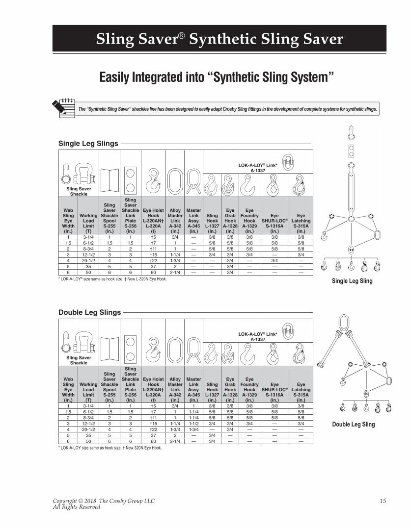
Sling Saver® Synthetic Sling Saver
The “Synthetic Sling Saver” shackles line has been designed to easily adapt Crosby Sling fittings in the development of complete systems for synthetic slings.
Sling SaverShackle
LOK-A-LOY® Link*A-1337
Web Sling Eye
Width(in.)
WorkingLoadLimit
(T)
SlingSaver
ShackleSpoolS-255(in.)
SlingSaver
ShackleLinkPlateS-256(in.)
Eye HoistHook
L-320AN†L-320A
(t)
AlloyMaster
LinkA-342(in.)
MasterLinkAssy.A-345(in.)
SlingHook
L-1327(in.)
EyeGrabHook
A-1328(in.)
EyeFoundry
HookA-1329
(in.)
EyeSHUR-LOC®
S-1316A(in.)
EyeLatchingS-315A
(in.)1 3-1/4 1 1 †5 3/4 — 3/8 3/8 3/8 3/8 3/8
1.5 6-1/2 1.5 1.5 †7 1 — 5/8 5/8 5/8 5/8 5/82 8-3/4 2 2 †11 1 — 5/8 5/8 5/8 5/8 5/83 12-1/2 3 3 †15 1-1/4 — 3/4 3/4 3/4 — 3/44 20-1/2 4 4 †22 1-3/4 — — 3/4 — 3/4 —5 35 5 5 37 2 — — 3/4 — — —6 50 6 6 60 2-1/4 — — 3/4 — — —
* LOK-A-LOY® size same as hook size. † New L-320N Eye Hook.
Single Leg Slings
Double Leg Slings
Sling SaverShackle
LOK-A-LOY® Link*A-1337
Web Sling Eye
Width(in.)
WorkingLoadLimit
(T)
SlingSaver
ShackleSpoolS-255(in.)
SlingSaver
ShackleLinkPlateS-256(in.)
Eye HoistHook
L-320AN†L-320A
(t)
AlloyMaster
LinkA-342(in.)
MasterLinkAssy.A-345(in.)
SlingHook
L-1327(in.)
EyeGrabHook
A-1328(in.)
EyeFoundry
HookA-1329
(in.)
EyeSHUR-LOC®
S-1316A(in.)
EyeLatchingS-315A
(in.)1 3-1/4 1 1 †5 3/4 1 3/8 3/8 3/8 3/8 3/8
1.5 6-1/2 1.5 1.5 †7 1 1-1/4 5/8 5/8 5/8 5/8 5/82 8-3/4 2 2 †11 1 1-1/4 5/8 5/8 5/8 5/8 5/83 12-1/2 3 3 †15 1-1/4 1-1/2 3/4 3/4 3/4 — 3/44 20-1/2 4 4 †22 1-3/4 1-3/4 — 3/4 — — —5 35 5 5 37 2 — 3/4 — — — —6 50 6 6 60 2-1/4 — 3/4 — — — —
* LOK-A-LOY size same as hook size. † New 320N Eye Hook.
Double Leg Sling
Single Leg Sling
Easily Integrated into “Synthetic Sling System”
Copyright © 2018 The Crosby Group LLCAll Rights Reserved
16
Sling Saver® Inspection Information
WEB SLING IDENTIFICATION INCLUDES:
SLING TYPE:TC – TRIANGLE CHOKERTT – TRIANGLE TRIANGLEEE – EYE AND EYEEN – ENDLESS
NUMBER OF PLIES: 1 OR 2WEBBING GRADE: 9 OR 6
SLING WIDTH (MM)
SLING LENGTH (MM)
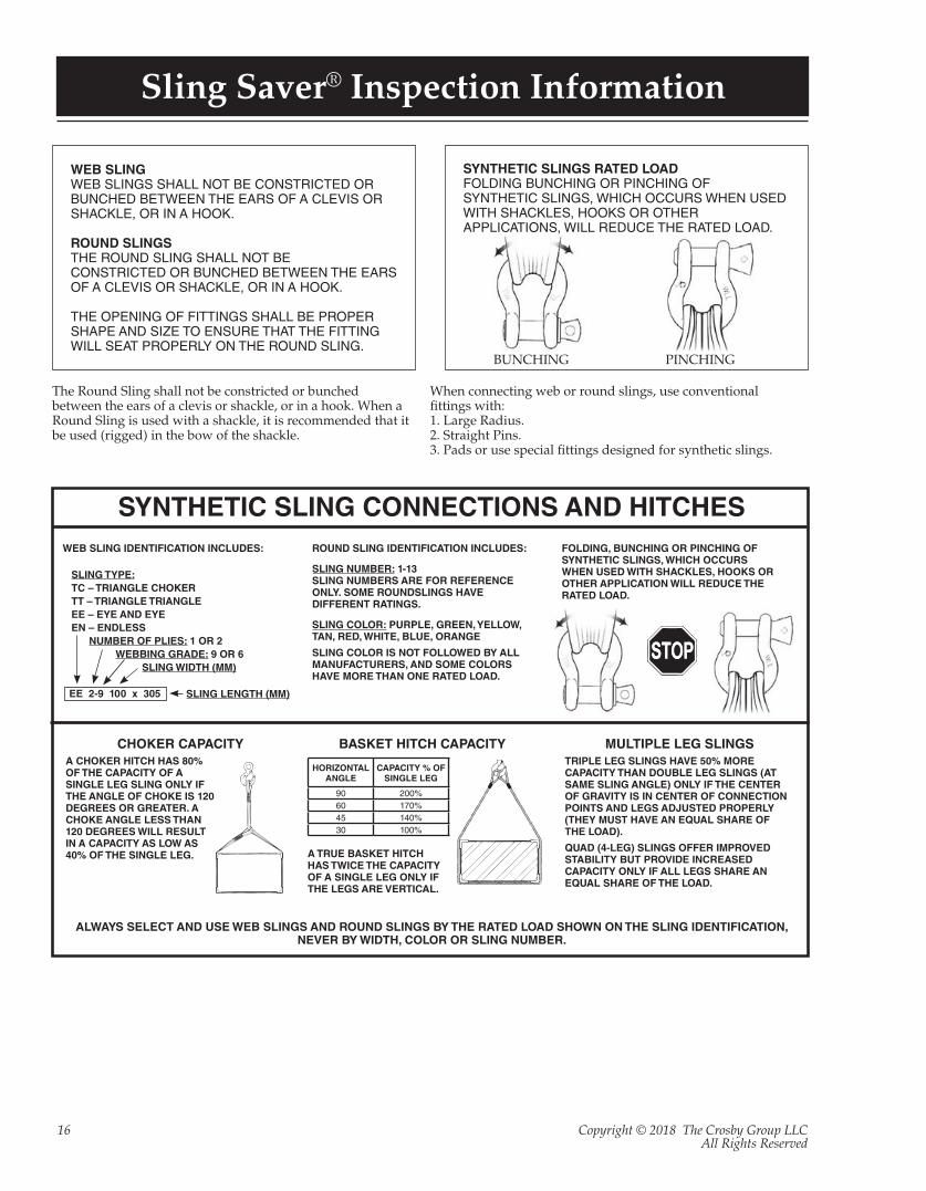
WEB SLINGWEB SLINGS SHALL NOT BE CONSTRICTED OR BUNCHED BETWEEN THE EARS OF A CLEVIS OR SHACKLE, OR IN A HOOK.
ROUND SLINGSTHE ROUND SLING SHALL NOT BE CONSTRICTED OR BUNCHED BETWEEN THE EARS OF A CLEVIS OR SHACKLE, OR IN A HOOK.
THE OPENING OF FITTINGS SHALL BE PROPER SHAPE AND SIZE TO ENSURE THAT THE FITTING WILL SEAT PROPERLY ON THE ROUND SLING.
SYNTHETIC SLINGS RATED LOAD FOLDING BUNCHING OR PINCHING OF SYNTHETIC SLINGS, WHICH OCCURS WHEN USED WITH SHACKLES, HOOKS OR OTHER APPLICATIONS, WILL REDUCE THE RATED LOAD.
PINCHINGBUNCHING
The Round Sling shall not be constricted or bunched between the ears of a clevis or shackle, or in a hook. When a Round Sling is used with a shackle, it is recommended that it be used (rigged) in the bow of the shackle.
When connecting web or round slings, use conventional fittings with:1. Large Radius.2. Straight Pins.3. Pads or use special fittings designed for synthetic slings.
SYNTHETIC SLING CONNECTIONS AND HITCHES
EE 2-9 100 x 305
ROUND SLING IDENTIFICATION INCLUDES:
SLING NUMBER: 1-13SLING NUMBERS ARE FOR REFERENCE ONLY. SOME ROUNDSLINGS HAVE DIFFERENT RATINGS.
SLING COLOR: PURPLE, GREEN, YELLOW, TAN, RED, WHITE, BLUE, ORANGE
SLING COLOR IS NOT FOLLOWED BY ALL MANUFACTURERS, AND SOME COLORS HAVE MORE THAN ONE RATED LOAD.
MULTIPLE LEG SLINGSTRIPLE LEG SLINGS HAVE 50% MORE CAPACITY THAN DOUBLE LEG SLINGS (AT SAME SLING ANGLE) ONLY IF THE CENTER OF GRAVITY IS IN CENTER OF CONNECTION POINTS AND LEGS ADJUSTED PROPERLY (THEY MUST HAVE AN EQUAL SHARE OF THE LOAD).
QUAD (4-LEG) SLINGS OFFER IMPROVED STABILITY BUT PROVIDE INCREASED CAPACITY ONLY IF ALL LEGS SHARE AN EQUAL SHARE OF THE LOAD.
FOLDING, BUNCHING OR PINCHING OF SYNTHETIC SLINGS, WHICH OCCURS WHEN USED WITH SHACKLES, HOOKS OR OTHER APPLICATION WILL REDUCE THE RATED LOAD.
CHOKER CAPACITYA CHOKER HITCH HAS 80% OF THE CAPACITY OF A SINGLE LEG SLING ONLY IF THE ANGLE OF CHOKE IS 120 DEGREES OR GREATER. A CHOKE ANGLE LESS THAN 120 DEGREES WILL RESULT IN A CAPACITY AS LOW AS 40% OF THE SINGLE LEG.
BASKET HITCH CAPACITY
A TRUE BASKET HITCH HAS TWICE THE CAPACITY OF A SINGLE LEG ONLY IF THE LEGS ARE VERTICAL.
HORIZONTALANGLE
CAPACITY % OFSINGLE LEG
90 200%60 170%45 140%30 100%
ALWAYS SELECT AND USE WEB SLINGS AND ROUND SLINGS BY THE RATED LOAD SHOWN ON THE SLING IDENTIFICATION, NEVER BY WIDTH, COLOR OR SLING NUMBER.
Copyright © 2018 The Crosby Group LLCAll Rights Reserved
17
Sling Saver® Inspection of Fittings
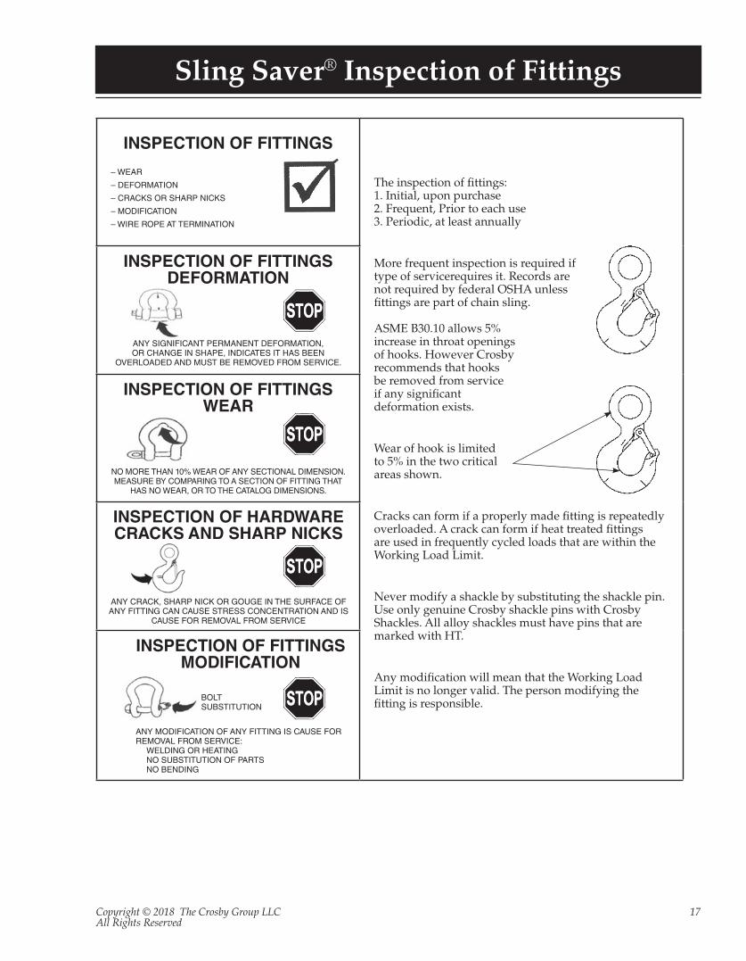
INSPECTION OF FITTINGS
– WEAR
– DEFORMATION
– CRACKS OR SHARP NICKS
– MODIFICATION
– WIRE ROPE AT TERMINATION
The inspection of fittings:1. Initial, upon purchase2. Frequent, Prior to each use3. Periodic, at least annually
More frequent inspection is required iftype of servicerequires it. Records are not required by federal OSHA unless fittings are part of chain sling.
ASME B30.10 allows 5% increase in throat openingsof hooks. However Crosbyrecommends that hooksbe removed from serviceif any significantdeformation exists.
Wear of hook is limited to 5% in the two criticalareas shown.
Cracks can form if a properly made fitting is repeatedlyoverloaded. A crack can form if heat treated fittingsare used in frequently cycled loads that are within the Working Load Limit.
Never modify a shackle by substituting the shackle pin.Use only genuine Crosby shackle pins with CrosbyShackles. All alloy shackles must have pins that are marked with HT.
Any modification will mean that the Working Load Limit is no longer valid. The person modifying the fitting is responsible.
INSPECTION OF FITTINGSDEFORMATION
ANY SIGNIFICANT PERMANENT DEFORMATION, OR CHANGE IN SHAPE, INDICATES IT HAS BEEN
OVERLOADED AND MUST BE REMOVED FROM SERVICE.
INSPECTION OF FITTINGSWEAR
NO MORE THAN 10% WEAR OF ANY SECTIONAL DIMENSION. MEASURE BY COMPARING TO A SECTION OF FITTING THAT
HAS NO WEAR, OR TO THE CATALOG DIMENSIONS.
INSPECTION OF FITTINGSMODIFICATION
ANY MODIFICATION OF ANY FITTING IS CAUSE FOR REMOVAL FROM SERVICE:
WELDING OR HEATINGNO SUBSTITUTION OF PARTSNO BENDING
BOLTSUBSTITUTION
INSPECTION OF HARDWARECRACKS AND SHARP NICKS
ANY CRACK, SHARP NICK OR GOUGE IN THE SURFACE OF ANY FITTING CAN CAUSE STRESS CONCENTRATION AND IS
CAUSE FOR REMOVAL FROM SERVICE
Copyright © 2018 The Crosby Group LLCAll Rights Reserved
18
Sling Saver® Inspection of Round Slings
INSPECTION OF POLYESTER ROUND SLINGS:WEB SLING AND TIE DOWN ASSOCIATION
Type of Inspectiona. Initial Inspection – Before any polyester round sling is placed into service it shall be inspected by a desig-
nated person to ensure that the correct round sling is being used, as well as to determine that the round sling meets the requirements of this specification.
b. Frequent Inspection – This inspection shall be made by a qualified person handling the polyester round sling each time the round sling is used.
c. Periodic Inspection – This inspection shall be conducted by a designated person.d. Frequency of inspection should be based on:
1. Frequency of use.2. Severity of service conditions.3. Experience gained on service life of polyester round sling used in similar applications.4. Periodic inspection should be conducted at least monthly.
Removal from ServiceA polyester round sling shall be removed from service if any of the following is visible:
a. If polyester round sling identification is missing or unreadable.b. Melting, charring or weld spatter on any part of the polyester round sling.c. Holes, tears, cuts, embedded particles, abrasive wear, or snags that expose thecore fibers of the polyester round sling.d. Broken or worn stitching in the cover which exposes the core fibers.e. Fittings when damaged, stretched or distorted in any way.f. Polyester round sling that is knotted.g. Acid or alkali burns of the polyester round sling.h. Any conditions which cause doubt as to the strength of the polyester round sling.
OPERATION OF POLYESTER ROUND SLINGS:WEB SLING AND TIE DOWN ASSOCIATION
✔ Determine weight of the load. The weight of the load shall be within the rated capacity of the polyester round slings(s).
✔ Select a polyester round sling having suitable characteristics for the type of load, hitch and environment.
✔ Polyester round slings shall not be loaded in excess of the rated capacity. Consideration shall be given to the round sling to load angle which affects rated capacities. (See WSTDA-RS1 Section 2.10.5)
✔ Polyester round slings with fittings which are used in a choking hitch shall be sufficient length to assure that the choking action is on the round sling, and never on the fittings.
✔ Polyester round slings used in a basket hitch shall have the load balanced to prevent slippage.
✔ The opening in fittings shall be the proper shape and size to ensure that the fittings will seat properly in the polyester round sling, crane hook, or other attachments.
✔ Polyester round slings shall always be protected from being cut by sharp corners, sharp edges and edges that are not adequately rounded to a suitable radius, protrusions, or abrasive surfaces.
✔ Polyester round slings shall not be dragged on the floor or over an abrasive surface.
✔ Polyester round slings shall not be twisted, shortened, lengthened, tied into knots, or joined by knotting.
✔ Polyester round slings shall not be pulled from under loads when the load is resting on the polyester round sling.
✔ Do not drop polyester round slings equipped with metal fittings.
✔ Polyester round slings that appear to be damaged shall
not be used unless inspected and accepted as useable under WSTDA-RS1 Section 4.4 and 4.5
✔ The polyester round sling shall be hitched in a manner providing control of the load.
✔ Personnel, including all portions of the human body, shall be kept from between the polyester round sling and the load, and from between the polyester round sling and the crane hook or hoist hook. Personnel shall stand clear of the suspended load.
✔ Personnel shall not ride the polyester round sling. ✔ Shock loading shall be avoided. ✔ Twisting the leg (branches) shall be avoided. ✔ Load applied to a hook shall be centered in the bowl of the hook to prevent point loading.
✔ During lifting, with or without the load, personnel shall be alert for possible snagging of the polyester round sling.
✔ The polyester round slings shall be long enough so the rated capacity is adequate when the sling to load angle is taken into consideration. (See WSTDA-RS1 Section 2.10.5)
✔ Only Polyester round slings with legible identification tags shall be used.
✔ Tags and labels should be kept away from the load, hook and point of choke.
✔ The polyester round sling shall not be constricted or bunched between the ears of the clevis or shackle, or in a hook. When a polyester round sling is used with a shackle, it is recommended that it be used (rigged) in the bow of the shackle.
✔ Place blocks under load prior to setting down the load, to allow removal of the polyester round slings, if applicable.

Copyright © 2018 The Crosby Group LLCAll Rights Reserved
19
Sling Saver® Inspection of Web Slings
SECTION 9-5.9: INSPECTION, REMOVAL AND REPAIR
Initial InspectionPrior to use, all new, altered, modified, or repaired slings shall
be inspected by a designated person to verify compliance with the applicable provisions of this chapter.
Frequent Inspection(a) A visual inspection for damage shall be performed by the user
or other designated person each day or shirt the sling is used.(b) Conditions such as those listed in para. 9-5.9.4 or any other
condition that may result in a hazard shall cause the sling to be removed from service. Slings shall not be returned to service until approved by a qualified person.
(c) Written records are not required for frequent inspections.
Periodic Inspection(a) A complete inspection for damage to the sling shall be
periodically performed by a designated person. Each sling and component shall be examined individually, taking care to expose and examine all surfaces. The sling shall be examined for conditions such as those listed in para. 9-5.9.4 and a determination made as to whether they constitute a hazard.
(b) Periodic Inspection Frequency. Periodic inspection intervals shall not exceed 1 yr. The frequency of periodic inspections should be based on
(1) frequency of sling use(2) severity of service conditions(3) nature of lifts being made(4) experience gained on the service life of lings used in similar
circumstances(c) Guidelines for the time intervals are
(1) normal service – yearly(2) severe service – monthly to quarterly(3) special service – as recommended by a qualified person
(d) Documentation that the most recent periodic inspection was performed shall be maintained.
(e) Inspection records of individual slings are not required.
Removal CriteriaA synthetic webbing sling shall be removed from service if
conditions such as the following are present:(a) missing or illegible sling identification (see Section 9-5.7)(b) acid or caustic burns(c) melting or charring of any part of the sling(d) holes, tears, cuts, or snags(e) broken or worn stitching in load bearing splices(f) excessive abrasive wear(g) knots in any part of the sling(h) discoloration and brittle or stiff areas on any part of the sling,
which may mean chemical or ultraviolet/sunlight damage(i) fittings that are pitted, corroded, cracked, bent, twisted, gouged,
or broken(j) for hooks, removal criteria as stated in ASME B30.10(k) for rigging hardware, removal criteria as stated in ASME B30.26(l) other conditions, including visible damage, that cause doubt as
to the continued use of the sling
OPERATING PRACTICES
Sling Selection(a) Slings that appear to be damaged shall not be used unless
inspected and accepted as usable under Section 9-5.9.(b) Slings having suitable characteristics for the type of load,
hitch, and environment shall be selected in accordance with the requirements of Sections 9-5.5 and 9-5.8.
INSPECTION, OPERATION, REMOVAL, AND REPAIR – ASME B30.9-2010(c) The rated load of the sling shall not be exceeded.(d) For multiple-leg slings used with nonsymmetrical loads, an
analysis by a qualified person should be performed to prevent overloading of any leg.
(e) Multiple-leg slings shall be selected according to Tables 9-5.5.2-1 through 9-5.5.2-5 when used at the specific angles given in the table. Operation at other angles shall be limited to rated loads of the next lower angle given in the table or calculated by a qualified person.
(f) Pin diameters smaller than those shown in WSTDA-WS-I may reduce the rated load of the sling.
(g) The fitting shall be of the proper shape and size to ensure that it is seated properly in the hook or lifting device.
Effects of Environment(a) Slings should be stored in an area where they will not be
subjected to mechanical, chemical, or ultraviolet damage or extreme temperatures (see Section 9-5.8).
(b) When used at or in contact with extreme temperatures the guidance provided in Section 9-5.8 shall be followed.
(c) When extensive exposure to sunlight or ultraviolet light is experienced by nylon or polyester webbing slings, the sling manufacturer should be consulted for recommended inspection procedure.
Rigging Practices(a) Slings shall be shortened or adjusted only by methods
approved by the sling manufacturer or a qualified person.(b) Slings shall not be shortened or lengthened by knotting or twisting.(c) The sling shall be hitched in a manner providing control of the load.(d) Slings in contact with edges, corners, protrusions, or abrasive
surfaces shall be protected with a material of sufficient strength, thickness, and construction to prevent damage.
(e) Shock loading should be avoided.(f) Loads should not be rested on the sling.(g) Slings should not be pulled from under a load when the load is
resting on the sling.(h) Twisting shall be avoided.(i) During lifting, with or without load, personnel shall be alert for
possible snagging.(j) When using multiple basket or choker hitches, the load should
be rigged to prevent the sling from slipping or sliding along the load.
(k) When using a basket hitch, the legs of the sling should contain or support the load from the sides, above the center of gravity, so that the load remains under control.
(l) Slings should not be dragged on the floor or over an abrasive surface.
(m) In a choker hitch, the choke point should only be on the sling body, not on a load-bearing splice or fitting.
(n) In a choker hitch, an angle of choke less than 120 deg should not be used without reducing the rated load (see para. 9-5.5.5).
(o) Slings should not be constricted, bunched, or pinched by the load, hook, or any fitting.
(p) The load applied to the hook should be centered in the base (bowl) of the hook to prevent point loading on the hook, unless the hook is designed for point loading.
(q) An object in the eye of a sling should not be wider than one-third the length of the eye.
“Reprinted from ASME B30.9-2010 by permission of The American Society of Mechanical Engineers”. All rights reserved.” No further copies can be made without written permission.
9999695 PPG5M 11/12/18 www.thecrosbygroup.com
United States2801 Dawson RoadTulsa, OK 74110P: (918) 834-4611F: (918) [email protected]
Canada3660 Odyssey Drive, Unit 4 Mississauga, Ontario,Canada L5M [email protected]
EuropeIndustriepark Zone b N°262220 Heist-op-den-BergBelgiumP: (+32) (0)15 75 71 25F: (+32) (0)15 75 37 [email protected]
Crosby Group Products Distributed By: