ACCESS TO MARS - space.nss.orgspace.nss.org/media/Access-To-Mars.pdf · Types of Mars Expeditions...
109
ACCESS TO MARS: (Part 1) EARTH TO MARS TRANSIT - LOGISTICS ALTERNATIVES John K. Strickland, Jr. ([email protected] ) Presented at the International Space Development Conference Huntsville, Alabama, May 18-22, 2011 Initial version presented at the 13th International Mars Society Convention, Dayton, Ohio, August 5-8, 2010
Transcript of ACCESS TO MARS - space.nss.orgspace.nss.org/media/Access-To-Mars.pdf · Types of Mars Expeditions...
ACCESS TO MARS: (Part 1) EARTH TO MARS TRANSIT -
LOGISTICS ALTERNATIVES John K. Strickland, Jr. ([email protected])
Presented at theInternational Space Development
ConferenceHuntsville, Alabama, May 18-22, 2011
Initial version presented at the 13th International Mars Society Convention,
Dayton, Ohio, August 5-8, 2010
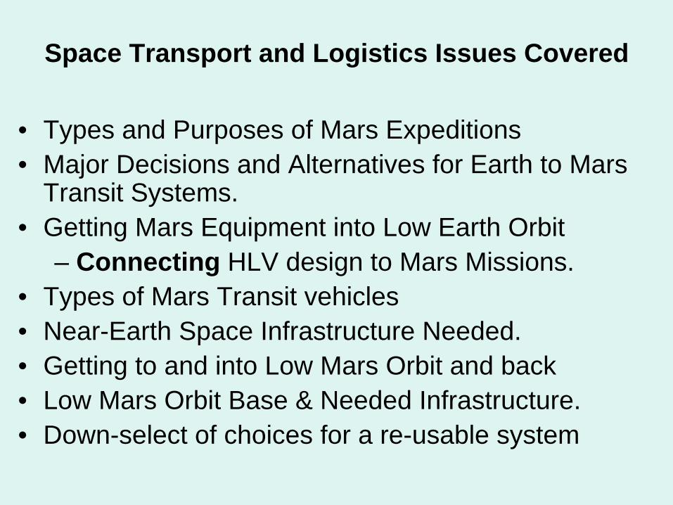
Space Transport and Logistics Issues Covered
• Types and Purposes of Mars Expeditions• Major Decisions and Alternatives for Earth to Mars
Transit Systems.• Getting Mars Equipment into Low Earth Orbit
– Connecting HLV design to Mars Missions.• Types of Mars Transit vehicles• Near-Earth Space Infrastructure Needed.• Getting to and into Low Mars Orbit and back• Low Mars Orbit Base & Needed Infrastructure.• Down-select of choices for a re-usable system
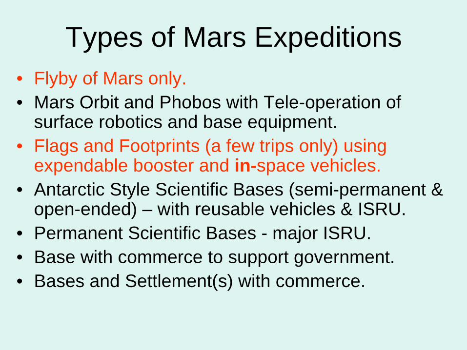
Types of Mars Expeditions• Flyby of Mars only.• Mars Orbit and Phobos with Tele-operation of
surface robotics and base equipment.• Flags and Footprints (a few trips only) using
expendable booster and in-space vehicles.• Antarctic Style Scientific Bases (semi-permanent &
open-ended) – with reusable vehicles & ISRU.• Permanent Scientific Bases - major ISRU.• Base with commerce to support government.• Bases and Settlement(s) with commerce.
Rational for avoiding “Flags and Footprints” Missions
• F&F is a dead end road. If you build a "flags and footprints" (non-re-usable) architecture, then all you will get is a short series of flags and footprints missions. Period. This path is not sustainable due to the continuing high cost of building replacement vehicles.
• There could be a very long gap afterward before Human Mars exploration is resumed, just like the one after Apollo.
• This creates a risk of loss of public interest and support similar to the post-Apollo period.
• It creates no Mars infrastructure usable for future missions.• It is inefficient and produces relatively few scientific results
for the money spent.• (The most important Mars Direct Concepts – such as
equipment pre-positioning and using local materials - are very useful for many kinds of missions).
How to avoid Flags and Footprints• Create a fleet of re-usable, preferably air-breathing HLV
Boosters, operated by private companies, to greatly reduce cost of launching payloads to LEO.
• Make it a policy to design all in-space vehicles to be re- usable except in very specific situations.
• Create an in-space infrastructure of propellant depots and crew refuges using fallback base & redundant equipment concepts, similar to those used on Everest expeditions.
• Create a powerful, compact electric power source to operate VASIMR engines for Mars Transit. (Alternate method).
• Conduct all manned Mars operations as an international enterprise to share costs, with each country contributing one or more major components.
• Plan missions to be on-going without major interruptions.
Interdependency of Manned Mars Entry Vehicle Types with Booster Diameter
• You cannot assemble a re-usable entry vehicle with an integral aero- shell in Earth orbit (no factory equipment and no manpower), so such vehicles must be launched intact from the surface.
• Two types of Mars Entry Vehicle concepts exist:– 1. Wide base – Blunt body (capsule shaped)– 2. Narrow Body – lifting body or cylindrically shaped
• Wide body (up to 15 meters wide at the base) landers are more stable and can carry more cargo since they need less fuel due to entry drag, but they need an HLV with a 10 meter or wider diameter.
• Narrow body landers carry less cargo but they can be launched on some currently projected HLV boosters with an 7-8 meter diameter.
• The booster’s launch cost must be affordable for dozens of launches per year to support a continuing Mars exploration program.
• We can choose a vehicle design based on the booster available OR we can pick a booster design to FIT the needs of the payload (the lander).
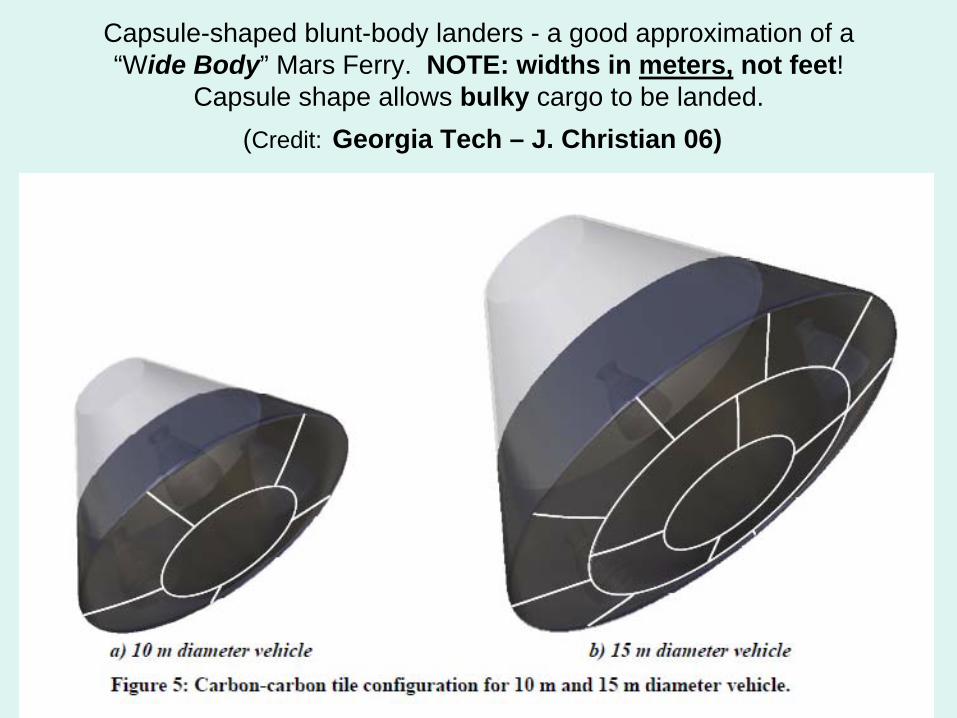
Capsule-shaped blunt-body landers - a good approximation of a “Wide Body” Mars Ferry. NOTE: widths in meters, not feet!
Capsule shape allows bulky cargo to be landed. (Credit: Georgia Tech – J. Christian 06)
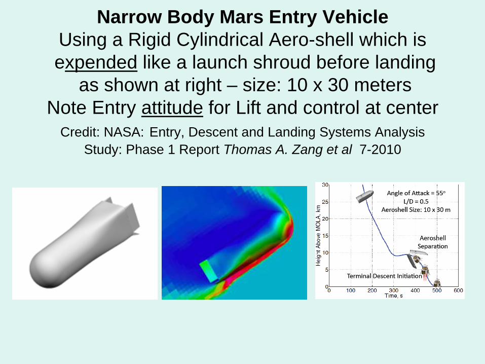
Narrow Body Mars Entry Vehicle Using a Rigid Cylindrical Aero-shell which is expended like a launch shroud before landing
as shown at right – size: 10 x 30 meters Note Entry attitude for Lift and control at center
Credit: NASA: Entry, Descent and Landing Systems Analysis Study: Phase 1 Report Thomas A. Zang et al 7-2010
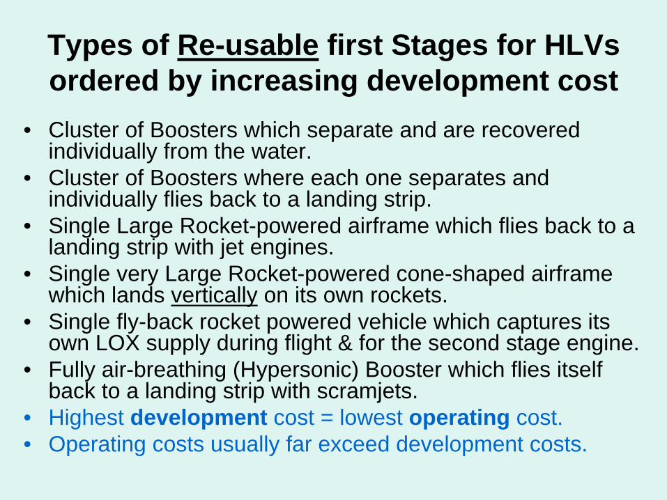
Types of Re-usable first Stages for HLVs ordered by increasing development cost
• Cluster of Boosters which separate and are recovered individually from the water.
• Cluster of Boosters where each one separates and individually flies back to a landing strip.
• Single Large Rocket-powered airframe which flies back to a landing strip with jet engines.
• Single very Large Rocket-powered cone-shaped airframe which lands vertically on its own rockets.
• Single fly-back rocket powered vehicle which captures its own LOX supply during flight & for the second stage engine.
• Fully air-breathing (Hypersonic) Booster which flies itself back to a landing strip with scramjets.
• Highest development cost = lowest operating cost.• Operating costs usually far exceed development costs.
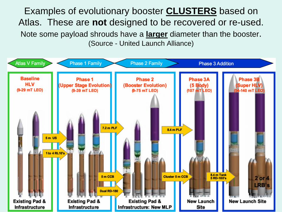
Examples of evolutionary booster CLUSTERS based on Atlas. These are not designed to be recovered or re-used. Note some payload shrouds have a larger diameter than the booster.
(Source - United Launch Alliance)
Why Solid Booster Based Rockets are NOT truly Re-usable
• Solid Rocket Propellant has to be manufactured and is very expensive compared to liquid fuel.
• The Solid Rocket Booster Casings have to be re-furbished after each mission.
• The Propellant then has to be cast inside the refurbished Casing using a mold.
• In effect, a solid rocket booster has to be Remanufactured each time it is used.
• The cost of re-using a solid booster is thus about 80% of the cost of a brand new solid booster.
Other Problems with Solids
• Continuing risk to space workers, crew, and buildings such as the VAB from accidental ignition of solid propellant.
• Once you turn Solid Boosters on, you cannot turn them off until all fuel is exhausted. One crew (Challenger) was already killed by solids.
• Solids exhaust produces a lot of air pollution and is creating an increasing public relations problem with environmentalists.
Desirable Near-Term HLV features• Re-usable first stage or first stage segments (required).• Airbreathing engine to increase payload mass.• Minimizing refurbishment to recovered stages, such as a stage that
flies back and lands like an airplane.• Flexible payload mass/size if a cluster.
• Very Wide payload capability to accommodate wide aero-shells, re- entry shields and vehicles (minimum 33 feet (10 meters) wide or more, up to 15 meters). Wider payloads can be launched with an inverted conical fairing, creating a “hammerhead” payload configuration, up to 50% wider diameter as the booster.7 meter (23 ft.) wide booster can launch a 10 meter wide payload8.4 meter booster (ET) can launch a 12.6 meter wide payload10 meter wide (33 ft) booster can launch a 15 meter (49 ft.) wide payload
• Large payload shroud volume to hold large integral structures with low density like habs.
• Ability to recover and re-use the second stage if possible.
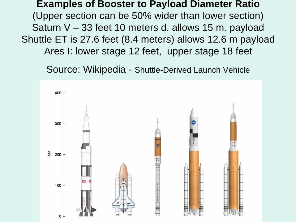
Examples of Booster to Payload Diameter Ratio (Upper section can be 50% wider than lower section) Saturn V – 33 feet 10 meters d. allows 15 m. payload
Shuttle ET is 27.6 feet (8.4 meters) allows 12.6 m payload Ares I: lower stage 12 feet, upper stage 18 feet
Source: Wikipedia - Shuttle-Derived Launch Vehicle
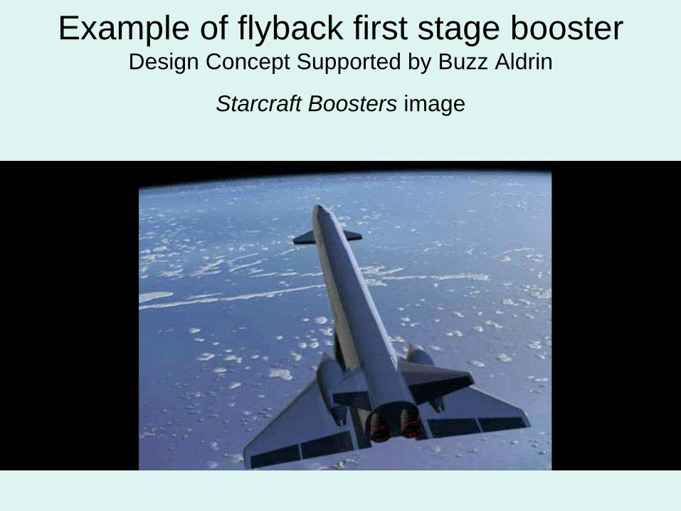
Example of flyback first stage booster Design Concept Supported by Buzz Aldrin
Starcraft Boosters image
Mars Transit: “Battlestar” configuration vs. multiple smaller independent vehicles
• Most previous plans for Mars missions have envisioned a single large composite vehicle carrying everything needed for an entire Human Mars Expedition leaving for Mars from Low Earth Orbit.
• Such a composite vehicle would mass many hundreds of tons with multiple connected segments and would have to have strong connections that could withstand thrusting without damage or leaks OR it would need to use a very low thrust (inefficient) departure.
• It would have to carry all the propellant, Mars landers, crew habitats, and food, water and equipment for the whole mission.
• Such a large, long vehicle would be very difficult to get into Low Mars orbit via aero-capture since any heat shield would need to be over 150 feet across or more, and would thus need to use a massive amount of fuel to brake into Mars Orbit.
• The alternative is to use a “fleet” of smaller, independent, compact vehicles, including crew vehicles, ferries, fuel depots and racks of payloads intended for use on the surface, which can all use aero-braking and also use full thrust on departure from Earth orbit.
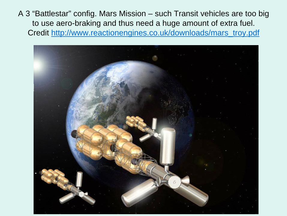
A 3 “Battlestar” config. Mars Mission – such Transit vehicles are too big to use aero-braking and thus need a huge amount of extra fuel.
Credit http://www.reactionengines.co.uk/downloads/mars_troy.pdf
Rationale for using Low Earth Orbit Propellant Depots with HLVs
• Most sources now show that Mars landers will need to have very wide diameters or bases: 10 meters (33 feet) or more.
• To use a lander on Mars, FIRST it needs to get to LEO.• Current ELV (small-diameter) launchers cannot launch such
wide payloads into LEO.• We need Mars landers that can carry very large payloads to
the surface - protected from re-entry heating.• We can launch much larger landers DRY than when WET.• If we launch them dry, we need orbital Propellant Depots to
accumulate propellants for Transit and Mars landing (EDL).• Without Depots, cryogenic propellants will sometimes boil off
before a crew can reach the vehicle to use it.• With Depots, the propellant in the first vehicle is not lost.• Building Propellant Depots should NOT be used as a
rationale for not building large Diameter HLV’s.
Buildup of Mars Fleet in LEO using HLVs and Use of Propellant Depot as a ‘Vehicle Accumulator’
• Vehicles and equipment are launched dry to LEO.• Mars Ferries may be able act as a second stage and
put themselves in orbit if fully fueled.• Space tugs move orbiting vehicles and cargo to depot
area and dock at adjacent assembly base.• External (non-integral) aero-capture shields are
attached to all Mars bound Transiting vehicles such as cargo carriers, crew Earth return vehicles and two Depots: LEO to LMO (Low Mars orbit).
• Ferries have integral aero-shells (as part of their vehicle structure).
• Cargo is loaded aboard cargo transit vehicles.• All Transit vehicles are fueled from large LEO Depot.
Mars “Fleet” prevents need for “Battlestar” vehicle and eliminates need for pre-positioning
• The preceding steps allow the accumulation of a large fleet of individual vehicles where fuel availability is guaranteed (in the depots) so that departure of many vehicles to Mars can be coordinated over a short period.
• This allows the departure of redundant vehicle types and eliminates the need for a 2 year delay after initial pre- positioning of equipment in Low Mars Orbit (LMO).
• Transit Vehicles in the fleet launch themselves from LEO to LMO (400 km high), reaching it by Aerocapture and orbit trim with OMS propellants only.
• OMS propellants could be either cryogenic or not.
Re-usable Crew and Cargo Transit vehicles• Crew transit and cargo vehicles left in Low Mars orbit can be re-
used to return to Earth orbit via aero-capture the same way they arrives at Mars. Cargo vehicles would return to Earth virtually empty. Both kinds would use interchangeable propulsion units.
• The crew Transit vehicles would consist of sections: water and food stores, inflatable crew habitat, crew radiation refuge and an external aero-shield.
• The cargo Transit vehicles would consist of thermally protected racks of 5-10, 20-25 ton cargo containers or large objects for delivery to the Martian surface. One kind would deliver a single large Depot full of cryogenic fuel.
• Both vehicles would have a large non-integral aero-shield, unlike the ferry vehicles, where the aero-shell is integral to the structure.
• Assuming that cryogenic propellant is available at both LEO and LMO (Low Mars orbit, both kinds of vehicle can leave powered by high Isp LOX-LH2 propellant and arrive via the aero-braking maneuver and orbit trim using non-cryogenic propellant.
• Cargo Transit vehicles would take the most efficient (slow) Hohmann orbit to Mars; Crew would take a fast transfer orbit.
Use of Propellant Depots and Tugs in LEO, Mars Transit and Mars Orbit
• Use of Cryogenic Propellant Depots allow all vehicles to be launched dry to LEO (with OMS fuel only) and then moved to a Depot for re-fueling.
• Allows transfer and storage of cyrogenic propellants without loss to boil-off (ZBO) using three methods: (1) sun-shields, (2) super-insulation, (3) cryo-coolers.
• Cryogenic propellants are taken to Low Mars Orbit Base from Earth in an active depot by a Mars transit propulsion vehicle.
• A Depot can operate with less refrigeration power at Mars orbit, but also gets less sunlight to power its equipment.
• Using cryogenic (Hydrogen-LOX) propellants allows re-use of vehicles without needing additional propellant from the Earth. All propellants for additional Ferry missions are supplied from the surface base. Methane-based propellants allow vehicle re- use but require most propellant re-supply in orbit from Earth.
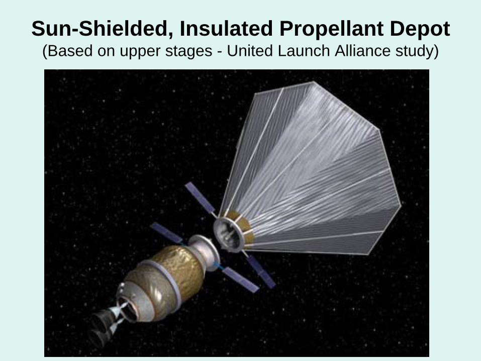
Sun-Shielded, Insulated Propellant Depot (Based on upper stages - United Launch Alliance study)
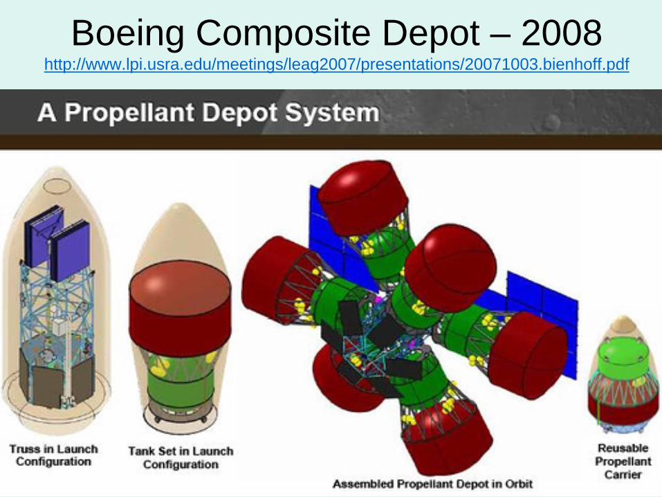
Boeing Composite Depot – 2008 http://www.lpi.usra.edu/meetings/leag2007/presentations/20071003.bienhoff.pdf
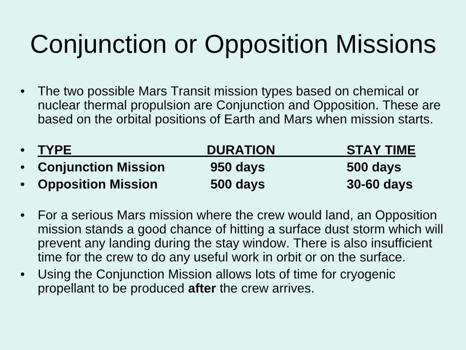
Conjunction or Opposition Missions• The two possible Mars Transit mission types based on chemical or
nuclear thermal propulsion are Conjunction and Opposition. These are based on the orbital positions of Earth and Mars when mission starts.
• TYPE DURATION STAY TIME• Conjunction Mission 950 days 500 days• Opposition Mission 500 days 30-60 days
• For a serious Mars mission where the crew would land, an Opposition mission stands a good chance of hitting a surface dust storm which will prevent any landing during the stay window. There is also insufficient time for the crew to do any useful work in orbit or on the surface.
• Using the Conjunction Mission allows lots of time for cryogenic propellant to be produced after the crew arrives.
VASIMR – a possible Transit Alternative• VASIMR is a very efficient plasma rocket system that, given a 200
Megawatt electrical power source, could reduce Mars Transit time to ~50 days from 6-8 months, greatly reducing crew exposure to solar radiation.
• This would save a huge mass of Mars Transit propellants.• VASIMR could widen windows for Mars Transit missions.• It reduces mission risk from damage to liquid fuel engines and loss of
liquid propellant accidents.• It could also move Mars-bound vehicles and cargo from LEO to GEO
before departure from GEO and maintain a Mars base orbit.• A current version is rated in tests at 250 KW. For Mars Transit
purposes, development should start now on a much larger and light weight space rated power supply needed to power VASIMR, such as a compact nuclear reactor, ultra-light solar panels, etc.
PROVISOS:• This System is NOT useful for Mars without the large power supply.• The use of chemical (cryogenic) propellants for Mars transit missions
is practical without waiting for a compact VASIMR power source.
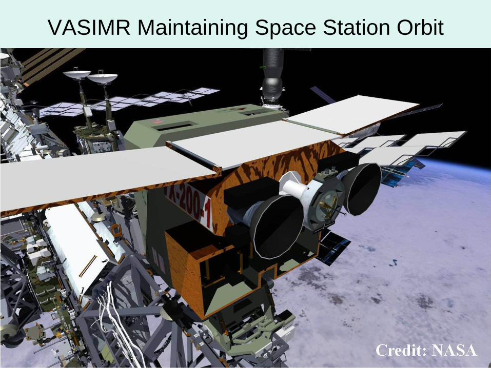
VASIMR Maintaining Space Station Orbit
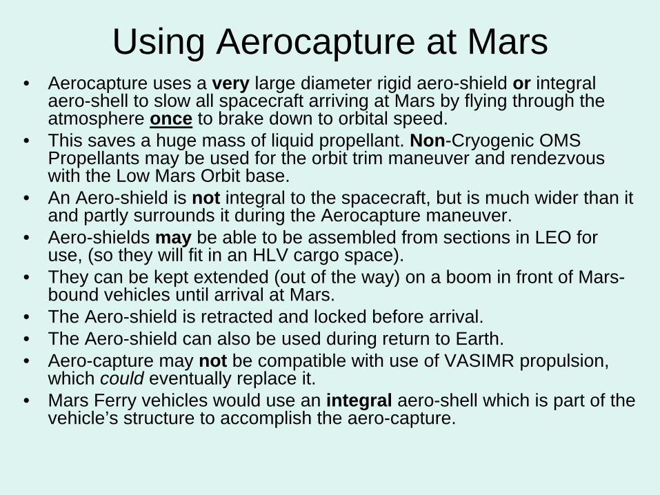
Using Aerocapture at Mars• Aerocapture uses a very large diameter rigid aero-shield or integral
aero-shell to slow all spacecraft arriving at Mars by flying through the atmosphere once to brake down to orbital speed.
• This saves a huge mass of liquid propellant. Non-Cryogenic OMS Propellants may be used for the orbit trim maneuver and rendezvous with the Low Mars Orbit base.
• An Aero-shield is not integral to the spacecraft, but is much wider than it and partly surrounds it during the Aerocapture maneuver.
• Aero-shields may be able to be assembled from sections in LEO for use, (so they will fit in an HLV cargo space).
• They can be kept extended (out of the way) on a boom in front of Mars- bound vehicles until arrival at Mars.
• The Aero-shield is retracted and locked before arrival.• The Aero-shield can also be used during return to Earth.• Aero-capture may not be compatible with use of VASIMR propulsion,
which could eventually replace it.• Mars Ferry vehicles would use an integral aero-shell which is part of the
vehicle’s structure to accomplish the aero-capture.
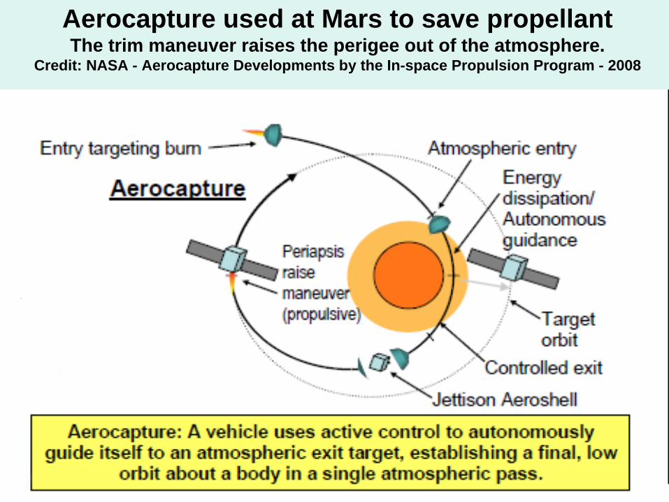
Aerocapture used at Mars to save propellant The trim maneuver raises the perigee out of the atmosphere.
Credit: NASA - Aerocapture Developments by the In-space Propulsion Program - 2008
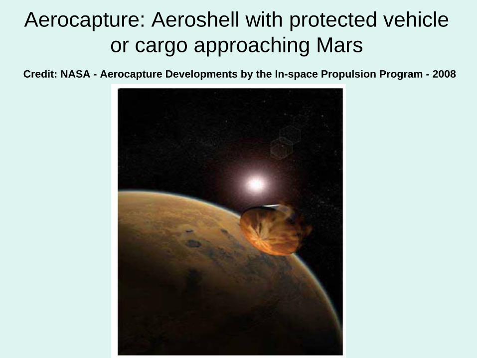
Aerocapture: Aeroshell with protected vehicle or cargo approaching Mars
Credit: NASA - Aerocapture Developments by the In-space Propulsion Program - 2008
Rationale and Policies for Designing a Low Mars Orbit Base
• A space-faring civilization needs to be able to operate both on planetary surfaces and in orbit for maximum effectiveness, such as increasing payloads to Mars per ton delivered from Earth.
• In-space operations and systems need to be designed to minimize man-hour requirements and maximize self- monitoring systems to reduce crew time. (Opposite of current space station design.)
• On-orbit systems should be able to operate for extended periods without crew directly on-board and with effective in- place redundancy and remote module switching capability.
• A 400 km circular orbit requires the least amount of propellant to reach from the surface of Mars, so that additional useful payloads can be brought down.
• This allows Ferries arriving individually in Mars orbit from Earth to access the Cryogenic Fuel Storage Depot and racks of payloads to be taken to the surface.
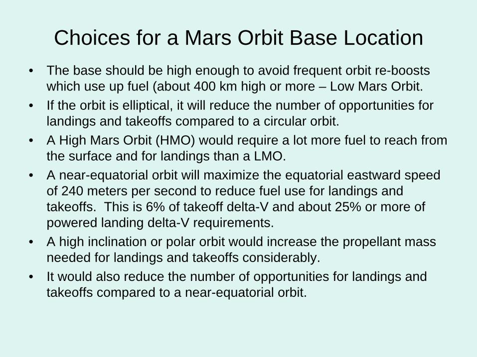
Choices for a Mars Orbit Base Location• The base should be high enough to avoid frequent orbit re-boosts
which use up fuel (about 400 km high or more – Low Mars Orbit.• If the orbit is elliptical, it will reduce the number of opportunities for
landings and takeoffs compared to a circular orbit.• A High Mars Orbit (HMO) would require a lot more fuel to reach from
the surface and for landings than a LMO.• A near-equatorial orbit will maximize the equatorial eastward speed
of 240 meters per second to reduce fuel use for landings and takeoffs. This is 6% of takeoff delta-V and about 25% or more of powered landing delta-V requirements.
• A high inclination or polar orbit would increase the propellant mass needed for landings and takeoffs considerably.
• It would also reduce the number of opportunities for landings and takeoffs compared to a near-equatorial orbit.
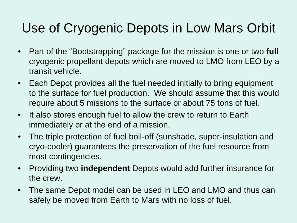
Use of Cryogenic Depots in Low Mars Orbit• Part of the “Bootstrapping” package for the mission is one or two full
cryogenic propellant depots which are moved to LMO from LEO by a transit vehicle.
• Each Depot provides all the fuel needed initially to bring equipment to the surface for fuel production. We should assume that this would require about 5 missions to the surface or about 75 tons of fuel.
• It also stores enough fuel to allow the crew to return to Earth immediately or at the end of a mission.
• The triple protection of fuel boil-off (sunshade, super-insulation and cryo-cooler) guarantees the preservation of the fuel resource from most contingencies.
• Providing two independent Depots would add further insurance for the crew.
• The same Depot model can be used in LEO and LMO and thus can safely be moved from Earth to Mars with no loss of fuel.
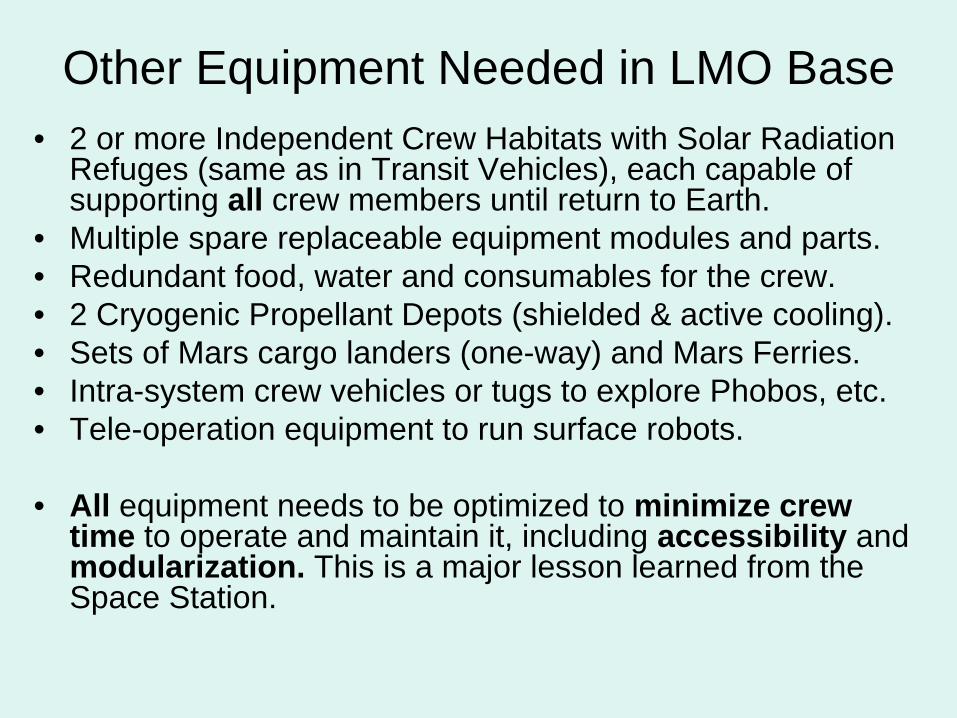
Other Equipment Needed in LMO Base• 2 or more Independent Crew Habitats with Solar Radiation
Refuges (same as in Transit Vehicles), each capable of supporting all crew members until return to Earth.
• Multiple spare replaceable equipment modules and parts.• Redundant food, water and consumables for the crew.• 2 Cryogenic Propellant Depots (shielded & active cooling).• Sets of Mars cargo landers (one-way) and Mars Ferries.• Intra-system crew vehicles or tugs to explore Phobos, etc.• Tele-operation equipment to run surface robots.
• All equipment needs to be optimized to minimize crew time to operate and maintain it, including accessibility and modularization. This is a major lesson learned from the Space Station.
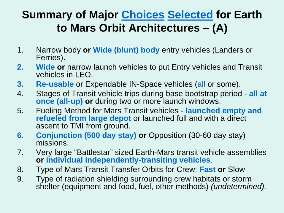
Summary of Major Choices Selected for Earth to Mars Orbit Architectures – (A)
1. Narrow body or Wide (blunt) body entry vehicles (Landers or Ferries).
2. Wide or narrow launch vehicles to put Entry vehicles and Transit vehicles in LEO.
3. Re-usable or Expendable IN-Space vehicles (all or some).4. Stages of Transit vehicle trips during base bootstrap period - all at
once (all-up) or during two or more launch windows.5. Fueling Method for Mars Transit vehicles - launched empty and
refueled from large depot or launched full and with a direct ascent to TMI from ground.
6. Conjunction (500 day stay) or Opposition (30-60 day stay) missions.
7. Very large “Battlestar” sized Earth-Mars transit vehicle assemblies or individual independently-transiting vehicles.
8. Type of Mars Transit Transfer Orbits for Crew: Fast or Slow9. Type of radiation shielding surrounding crew habitats or storm
shelter (equipment and food, fuel, other methods) (undetermined).
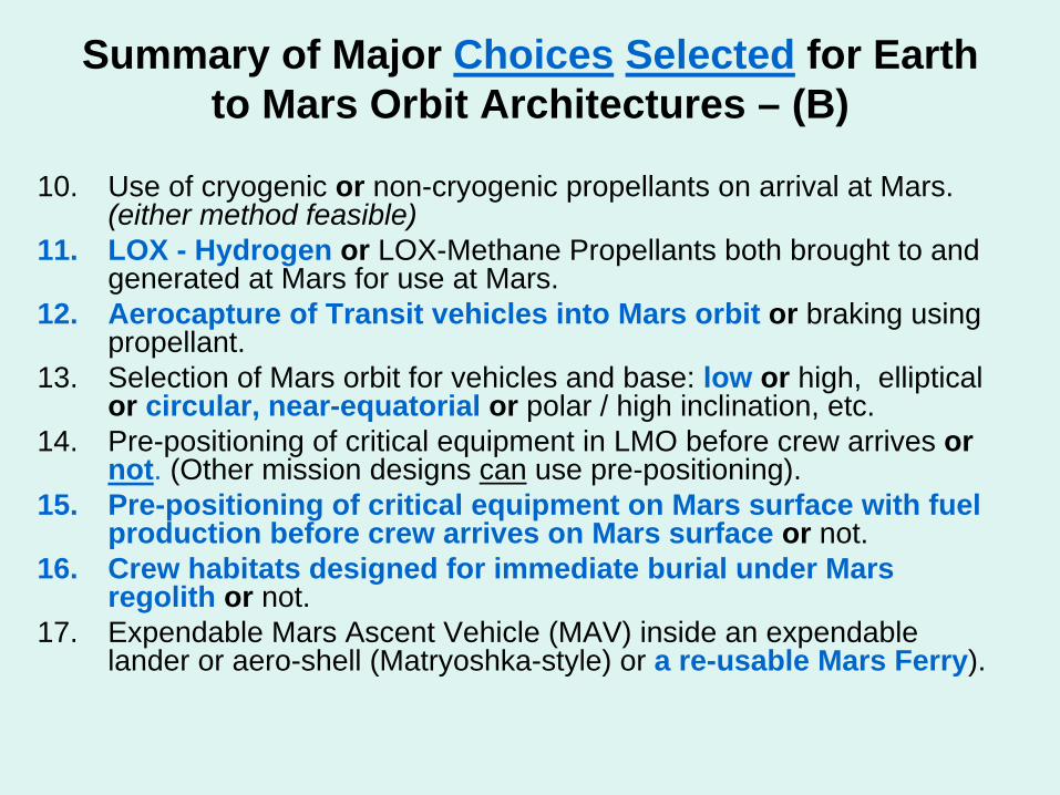
Summary of Major Choices Selected for Earth to Mars Orbit Architectures – (B)
10. Use of cryogenic or non-cryogenic propellants on arrival at Mars. (either method feasible)
11. LOX - Hydrogen or LOX-Methane Propellants both brought to and generated at Mars for use at Mars.
12. Aerocapture of Transit vehicles into Mars orbit or braking using propellant.
13. Selection of Mars orbit for vehicles and base: low or high, elliptical or circular, near-equatorial or polar / high inclination, etc.
14. Pre-positioning of critical equipment in LMO before crew arrives or not. (Other mission designs can use pre-positioning).
15. Pre-positioning of critical equipment on Mars surface with fuel production before crew arrives on Mars surface or not.
16. Crew habitats designed for immediate burial under Mars regolith or not.
17. Expendable Mars Ascent Vehicle (MAV) inside an expendable lander or aero-shell (Matryoshka-style) or a re-usable Mars Ferry).
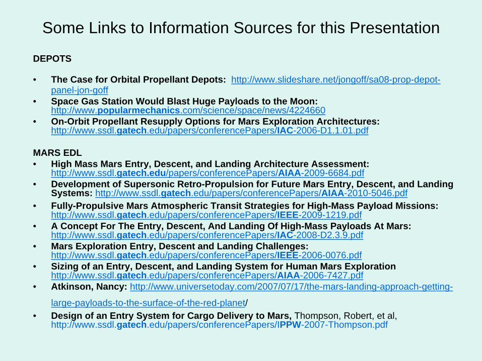
Some Links to Information Sources for this Presentation
DEPOTS
• The Case for Orbital Propellant Depots: http://www.slideshare.net/jongoff/sa08-prop-depot- panel-jon-goff
• Space Gas Station Would Blast Huge Payloads to the Moon: http://www.popularmechanics.com/science/space/news/4224660
• On-Orbit Propellant Resupply Options for Mars Exploration Architectures: http://www.ssdl.gatech.edu/papers/conferencePapers/IAC-2006-D1.1.01.pdf
MARS EDL• High Mass Mars Entry, Descent, and Landing Architecture Assessment:
http://www.ssdl.gatech.edu/papers/conferencePapers/AIAA-2009-6684.pdf• Development of Supersonic Retro-Propulsion for Future Mars Entry, Descent, and Landing
Systems: http://www.ssdl.gatech.edu/papers/conferencePapers/AIAA-2010-5046.pdf• Fully-Propulsive Mars Atmospheric Transit Strategies for High-Mass Payload Missions:
http://www.ssdl.gatech.edu/papers/conferencePapers/IEEE-2009-1219.pdf• A Concept For The Entry, Descent, And Landing Of High-Mass Payloads At Mars:
http://www.ssdl.gatech.edu/papers/conferencePapers/IAC-2008-D2.3.9.pdf• Mars Exploration Entry, Descent and Landing Challenges:
http://www.ssdl.gatech.edu/papers/conferencePapers/IEEE-2006-0076.pdf• Sizing of an Entry, Descent, and Landing System for Human Mars Exploration
http://www.ssdl.gatech.edu/papers/conferencePapers/AIAA-2006-7427.pdf• Atkinson, Nancy: http://www.universetoday.com/2007/07/17/the-mars-landing-approach-getting-
large-payloads-to-the-surface-of-the-red-planet/• Design of an Entry System for Cargo Delivery to Mars, Thompson, Robert, et al,
http://www.ssdl.gatech.edu/papers/conferencePapers/IPPW-2007-Thompson.pdf
ACCESS TO MARS: (Part 2) A Mars Transport and Logistics
System Based on a Fully Re-usable Mars Ferry John K. Strickland, Jr. ([email protected])
Presented at the30th International Space Development Conference
Huntsville, Alabama, May 18-22, 2011
Initial version presented at the 13th International Mars Society Convention,Dayton, Ohio, August 5-8, 2010
Mathematical modeling, vehicle sizing and EDL Simulation of the Mars SSTO Ferry are from online collaborative research with R.
Gopalaswami, Senior Aerospace Engineer (retired), Hyderabad, India
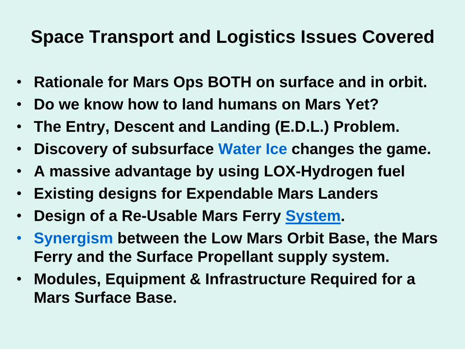
Space Transport and Logistics Issues Covered
•
Rationale for Mars Ops BOTH on surface and in orbit.•
Do we know how to land humans on Mars Yet?
•
The Entry, Descent and Landing (E.D.L.) Problem.•
Discovery of subsurface Water Ice changes the game.
•
A massive advantage by using LOX-Hydrogen fuel•
Existing designs for Expendable Mars Landers
•
Design of a Re-Usable Mars Ferry System.•
Synergism between the Low Mars Orbit Base, the Mars Ferry and the Surface Propellant supply system.
•
Modules, Equipment & Infrastructure Required for a Mars Surface Base.
We Cannot Land People on Mars Right Now !
•
We cannot land anything larger than the ~1 ton Mars Science Laboratory right now.
•
This is called the Mars EDL Problem (Entry, Descent and Landing).
•
No combination of available parachutes, re- entry shields and terminal descent rockets can land a 10 ton payload on Mars right now.
•
Minimal Crew Lander (expendable lander only) size is 20 tons, Cargo Landers and Re-usable Ferries probably weigh 60-200 tons.
•
Cargo Ferry should deliver 20+ tons to surface.•
Crew ferry includes a ~5 ton crew capsule.
The Leaders in this field confirm the facts
•
Two of the Leaders in this field are:•
Robert D. Braun, currently Chief Technologist for NASA, and Aerospace Professor of Space Technology at Georgia Institute of Technology, who just won the AIAA’s
Von Karman Award.
•
Robert Manning is the chief engineer for the Mars Science Lab Rover (JPL), previously was Mars Program Chief Engineer at JPL.
•
Much of this information on EDL is from papers by them and their Georgia Tech group of colleagues or writer’s interviews with them.
•
This problem first got serious attention in 2004.
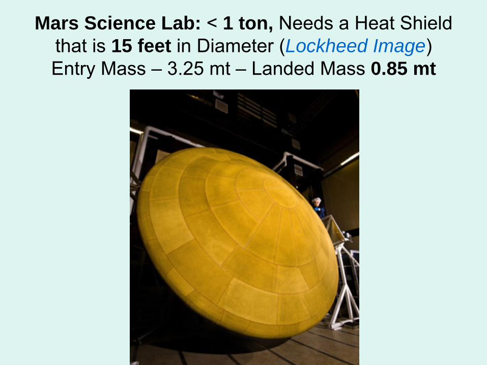
Mars Science Lab: < 1 ton, Needs a Heat Shield that is 15 feet in Diameter (Lockheed Image)
Entry Mass –
3.25 mt –
Landed Mass 0.85 mt
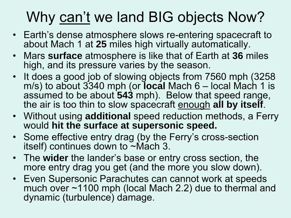
Why can’t
we land BIG objects Now?•
Earth’s dense atmosphere slows re-entering spacecraft to about Mach 1 at 25 miles high virtually automatically.
•
Mars surface atmosphere is like that of Earth at 36 miles high, and its pressure varies by the season.
•
It does a good job of slowing objects from 7560 mph (3258 m/s) to about 3340 mph (or local Mach 6 –
local Mach 1 is
assumed to be about 543 mph). Below that speed range, the air is too thin to slow spacecraft enough
all by itself.
•
Without using additional speed reduction methods, a Ferry would hit the surface at supersonic speed.
•
Some effective entry drag (by the Ferry’s cross-section itself) continues down to ~Mach 3.
•
The wider the lander’s
base or entry cross section, the more entry drag you get (and the more you slow down).
•
Even Supersonic Parachutes can cannot work at speeds much over ~1100 mph (local Mach 2.2) due to thermal and dynamic (turbulence) damage.
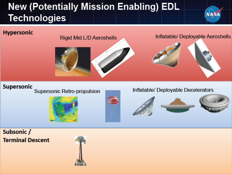
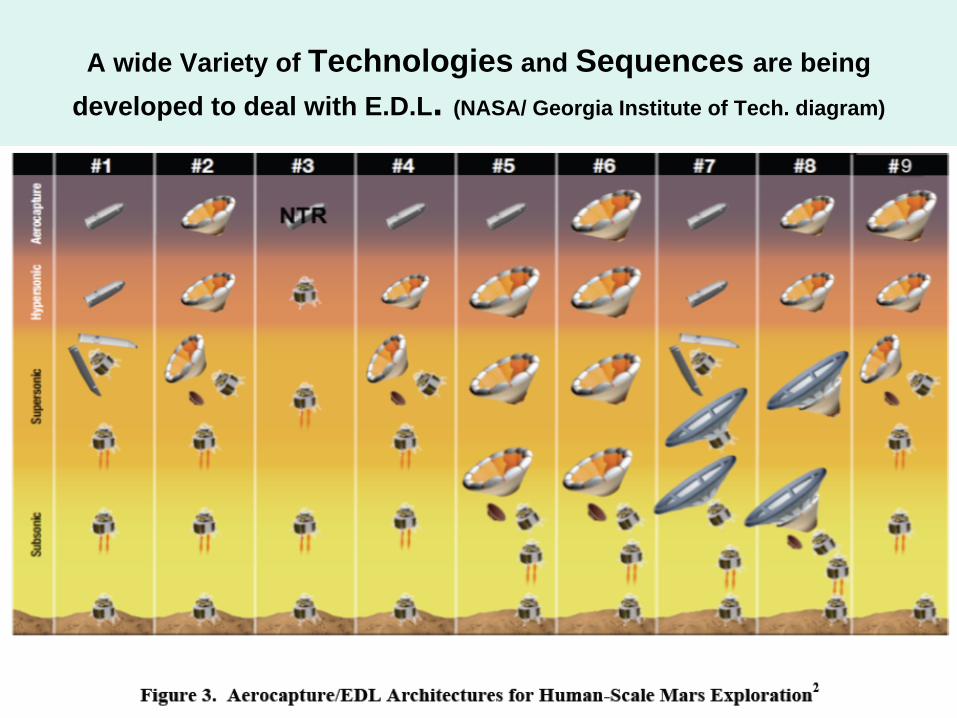
A wide Variety of Technologies and Sequences are being developed to deal with E.D.L. (NASA/ Georgia Institute of Tech. diagram)
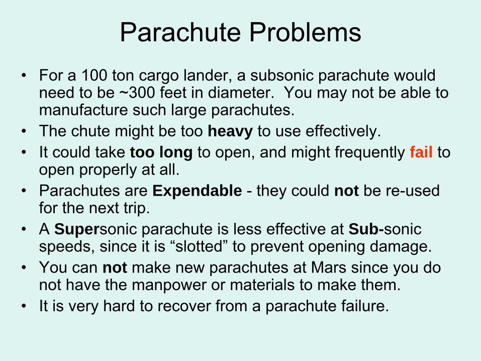
Parachute Problems•
For a 100 ton cargo lander, a subsonic parachute would need to be ~300 feet in diameter. You may not be able to manufacture such large parachutes.
•
The chute might be too heavy to use effectively.•
It could take too long to open, and might frequently fail to open properly at all.
•
Parachutes are Expendable -
they could not be re-used for the next trip.
•
A Supersonic parachute is less effective at Sub-sonic speeds, since it is “slotted”
to prevent opening damage.
•
You can not make new parachutes at Mars since you do not have the manpower or materials to make them.
•
It is very hard to recover from a parachute failure.
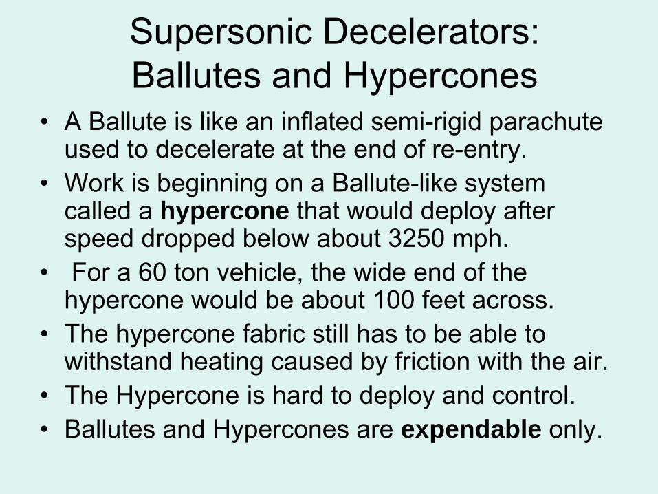
Supersonic Decelerators: Ballutes
and Hypercones
•
A Ballute
is like an inflated semi-rigid parachute used to decelerate at the end of re-entry.
•
Work is beginning on a Ballute-like system called a hypercone that would deploy after speed dropped below about 3250 mph.
•
For a 60 ton vehicle, the wide end of the hypercone
would be about 100 feet across.
•
The hypercone
fabric still has to be able to withstand heating caused by friction with the air.
•
The Hypercone
is hard to deploy and control.•
Ballutes and Hypercones
are expendable only.
Combinations are Required
if Supersonic Decelerators are used.Once speed drops below Mach 1, a subsonic parachute could be deployed.
•
Below about 1 kilometer, landing rocket engines would be needed to set the lander down gently.
•
This design requires 2 expendable systems, the Hypercone
and the subsonic parachute.
•
There is no way to recover and prevent a high speed crash if either the Hypercone
or the
parachute fails to open properly. A failed chute could also endanger separation of a crew cabin/escape capsule for abort to surface mode.
Atmosphere Problems•
All Mars landers need full heat shields and back shells for “re-entry”
from Mars orbit or directly from solar orbit.
•
We are glad that Mars does have an atmosphere, but if Mars had no atmosphere, it would be much easier to land on; it just would take more fuel.
•
On an airless Mars, descent rocket engines would fire continuously from some point along the descent transfer orbit down to the surface, just like landing on the Moon.
•
With
an atmosphere, the descent engines probably cannot fire during the peak period of re-entry.
•
However, they may be able to fire near the end of re- entry (at 3250 mph or about local Mach 6.)
Supersonic Retro Propulsion•
This method is called Supersonic Retro Propulsion (SRP).
It is now being taken seriously.
•
It requires rocket thrust firing directly through the heat shield and against the supersonic flow of air pressing against the base of the vehicle as it decelerates.
•
The rocket engines must be fixed in position with the nozzle ends flush with and sealed to the heat shield and thus they cannot gimbal
for steering.
•
Steering during re-entry and landing must be done by varying the thrust of a set of engines or by using side-mounted small vernier
engines.
Turbulence vs. Stability•
Thrusting directly against the air flow may cause extreme turbulence, endangering the vehicles stability, or it may increase
OR decrease
the
braking effect of the heat shield through which the rocket engines are firing, improving OR reducing the deceleration.
•
The rocket engines could be aimed directly forward, or placed along the edges of the heat shield and canted out at an angle from forward.
•
Very little work has ever been done on this method. It requires actual suborbital tests in the Earth’s atmosphere to prove which engine configurations and angles may work best.
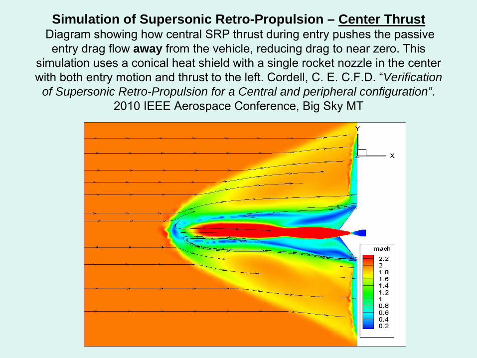
Simulation of Supersonic Retro-Propulsion – Center Thrust Diagram showing how central SRP thrust during entry pushes the passive entry drag flow away from the vehicle, reducing drag to near zero. This
simulation uses a conical heat shield with a single rocket nozzle in the center with both entry motion and thrust to the left. Cordell, C. E. C.F.D. “Verification
of Supersonic Retro-Propulsion for a Central and peripheral configuration”. 2010 IEEE Aerospace Conference, Big Sky MT
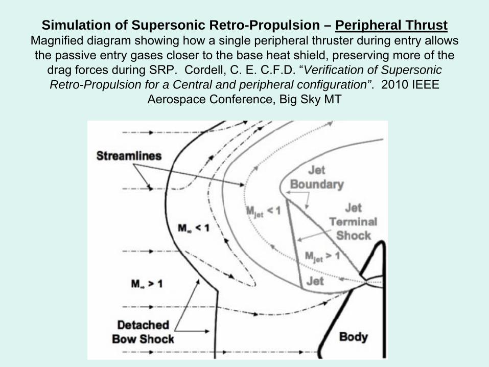
Simulation of Supersonic Retro-Propulsion – Peripheral Thrust Magnified diagram showing how a single peripheral thruster during entry allows the passive entry gases closer to the base heat shield, preserving more of the
drag forces during SRP. Cordell, C. E. C.F.D. “Verification of Supersonic Retro-Propulsion for a Central and peripheral configuration”. 2010 IEEE
Aerospace Conference, Big Sky MT
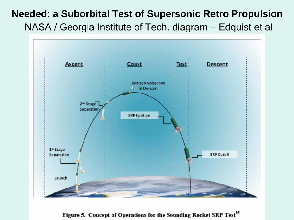
Needed: a Suborbital Test of Supersonic Retro Propulsion NASA / Georgia Institute of Tech. diagram –
Edquist
et al
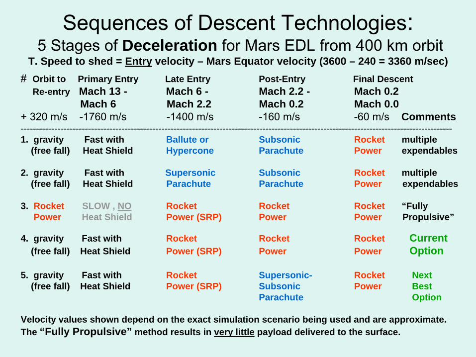
Sequences of Descent Technologies: 5 Stages of Deceleration for Mars EDL from 400 km orbit
T. Speed to shed = Entry velocity – Mars Equator velocity (3600 – 240 = 3360 m/sec)# Orbit to Primary Entry Late Entry Post-Entry Final Descent
Re-entry Mach 13 - Mach 6 - Mach 2.2 - Mach 0.2 Mach 6 Mach 2.2 Mach 0.2 Mach 0.0
+ 320 m/s
-1760 m/s
-1400 m/s
-160 m/s
-60 m/s
Comments---------------------------------------------------------------------------------------------------------------------------------------------1. gravity Fast with Ballute or Subsonic Rocket multiple
(free fall) Heat Shield Hypercone Parachute Power expendables
2. gravity Fast with Supersonic Subsonic Rocket multiple(free fall) Heat Shield Parachute Parachute Power expendables
3. Rocket SLOW , NO Rocket Rocket Rocket “Fully Power Heat Shield Power (SRP) Power Power Propulsive”
4. gravity Fast with Rocket Rocket Rocket Current(free fall) Heat Shield Power (SRP) Power Power Option
5. gravity Fast with Rocket Supersonic- Rocket Next(free fall) Heat Shield Power (SRP) Subsonic Power Best
Parachute Option
Velocity values shown depend on the exact simulation scenario being used and are approximate.The “Fully Propulsive” method results in very little payload delivered to the surface.
Banish the “Expendable Mentality” Think Re-Usable
!
•
Current scenarios for Manned Mars landings envision a very large lander which has, inside it , just like a nested Russian doll (Matryoshka), another entire vehicle for the ascent with its own engines, tanks, controls, structure, etc.
•
This means that every trip to the surface requires an entire additional pair of vehicles with all of the descent propellant brought from Earth.
•
It also wastes all of the perfectly good equipment in the descent vehicle or lander. This kind of architecture is only good for the kind of Mars expedition we do not want: the “Flags and Footprints”
style mission, which is financially un-
sustainable, and leads to the “one-way”
Mars trips currently being proposed by those desperate to see any kind of Manned Mars Mission during their lifetime.

Set of Russian Nested Dolls: Matryoshka, a Metaphor for
an object with another similar object inside it.

Narrow Body Mars Entry Vehicle Using a Rigid Cylindrical Aero-shell which is
expended like a launch shroud before landing as shown at right –
size: 10 x 30 meters
Note Entry attitude
for Lift and control at center Credit: NASA:
Entry, Descent and Landing Systems Analysis
Study: Phase 1 Report Thomas A. Zang et al 7-2010
The Case for Re-usable Mars Ferries•
Fewer ferries would need to be built , launched and shipped from Earth to Low Mars Orbit.
•
Provides additional backup vehicles for rescue.•
Allows swapping of internal equipment modules from older (retired) units (all designed for rapid swapping).
•
Increases reliability & safety after the first use of vehicle.•
Simplified designs -
most with few or no expendables.
•
Requires an integral (to vehicle) aeroshell for re-entry.•
Descent structure, engines and tanks can also be used for Ascent, which allows landed mass to be used more than once.
•
Two types: Cargo Ferry & Crew (has crew capsule).•
Each vehicle would be retired after about
10 flights
based on engineering reliability studies of components.
Designing a Re-Usable Mars FerryRe-usable vehicles using SRP can use their engines for:•
(1) Initial de-orbit burn: (7560 mph –
7400
mph) ~ Mach 13•
( ) “Passive”
Atmospheric Entry -
Deceleration (Mach 13 –
Mach 6)•
(2) Supersonic Retro-propulsion: (~Mach 6 -
Mach 0.9)•
(3) Subsonic Deceleration Mach 0.9 –
Mach 0.2•
(4) Final descent and landing: (Mach 0.2 / 100 mph to surface)•
(5) Ascent back into Low Mars Orbit.
•
With a fully re-usable vehicle, nothing is thrown away. Hydrogen and oxygen propellants can be created from Mars ice and volatiles, using a nuclear power source and carried back to orbit for use on the next trip down, since there is little cargo other than propellant that needs to go up.
•
Wide base vehicles with lower density slow down more during re-entry and thus need less propellant to land than a narrow base vehicle.
•
All of the propellants needed for Crew and Cargo Descent can be carried UP on ascent.
•
5 tons of
extra propellant
can be loaded back into the Propellant Depot in Low Mars Orbit from each Cargo
Ferry trip UP for use in Earth Return or access to Phobos
and Deimos.
A Single Stage to Orbit and Back Vehicle (SSTOAB) for Mars
•
The Mars Ferry is essentially an SSTO for Mars.•
Mars gravity is 0.38% of Earth’s, so achieving
low orbit is much easier than on earth -
about 2.5
miles per second.•
This takes only about ¼
of the energy
to reach L.E.O.•
Mars has 1/10 Earth mass, and 8 times lunar mass.•
If there is no staging, then there is no first stage to recover –
the entire vehicle goes to the Orbital “base”
and back to the surface base -
intact.•
Much less fuel is needed to land than take off to orbit since normal atmospheric re-entry sheds up to the first 4310 mph (1.7-
2.4 km/sec) of speed.
•
A cargo ferry would carry 25 tons of modules and equipment down to the surface and 20 tons of propellants back to orbit (15 tons to
use for descent and 5 tons for the Depot).
•
A
crew ferry (with its 5 ton crew cabin) would carry a crew with 20 tons of cargo down to the surface, and a crew and 15 tons of propellants back to orbit.
Discovery of Widespread Sub-Surface Ice on Mars makes propellant production a Non-Exotic operation
•
20 years ago, we had no knowledge of the widespread existence of Water
on Mars in the Form of Sub-surface ice deposits (ice regolith or permafrost), some of them fairly close to the equator.
•
Mars Direct (1989) and related concepts assumed we would bring the hydrogen to make methane fuel from all the way from Earth. Now the hydrogen
can be obtained from Mars ice in large enough quantities
to use as a fuel directly.
•
Producing propellants at a Mars surface base is NOT an exotic zero-gravity technology that still needs to be developed. All of the individual steps are already performed on Earth every day.
•
This avoids the need to first develop a technology to do it in micro-gravity, and allows a direct process of developing the hardware to do it under Mars conditions.
•
The extraction equipment and cryogenic storage system would be built in “package plant”
modules so that it could be set up easily by tele-operated robots, before crew members descend to the surface.
•
Any Surface Base Site would be influenced by the availability of
near-surface ice deposits that can be mined with simple excavation equipment.

Steps to create Propellant on Mars –
a standard sequence
•
Excavate and crush regolith and ice from surface strip mine using excavator and crusher. (The ice may be hard, and may require equipment similar to coal-mining grinders.)
•
Dump pulverized regolith with ice into pressurized hopper and melt the ice using power from a reactor.
•
Drain the water out of the regolith, dispose of the damp regolith, filter and purify the water.
•
Use Electrolysis or other process to produce hydrogen and oxygen gas from Water using electricity from reactor.
•
Liquefy the hydrogen and oxygen using reactor power.•
Store in insulated tanks and refrigerate using reactor power.
•
Bring propellants to launch site in insulated fuel tanker and fuel the Ascent configuration Ferry.
The case for using Cryogenic LOX-Hydrogen propellants instead of LOX-Methane.
•
LOX-Methane propellants, with their lower Specific Impulse, can only carry about 7 tons of cargo (as propellant) UP to orbit in a Ferry vs. about 20 tons for LOX-Hydrogen.
•
Methane would also take more propellants to land on Mars with less payload. This means that most of the propellant mass would still have to be supplied from Earth.
•
Hydrogen is harder to handle and store, but it has now been in use by the US for over 40 years, (2 generations) and we will have over 20 years to “ruggedize”
a LOX-Hydrogen
propellant system and automate handling and storage, reducing crew time and increasing reliability.
•
Since we will have the ability to maintain the cryogenic (LOX- H2) propellant supply both in orbit and on the surface, we
should use them, due to the huge advantage they give.•
The Bottom Line: LOX - Hydrogen has massive advantages !
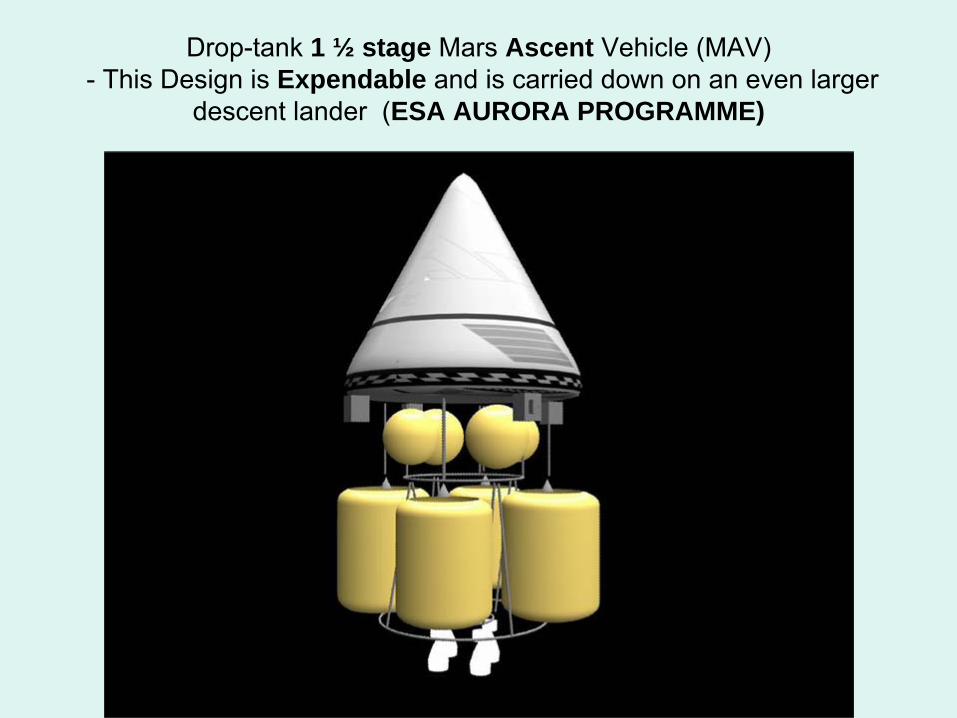
Drop-tank 1 ½ stage Mars Ascent Vehicle (MAV)
- This Design is Expendable and is carried down on an even larger descent lander (ESA AURORA PROGRAMME)
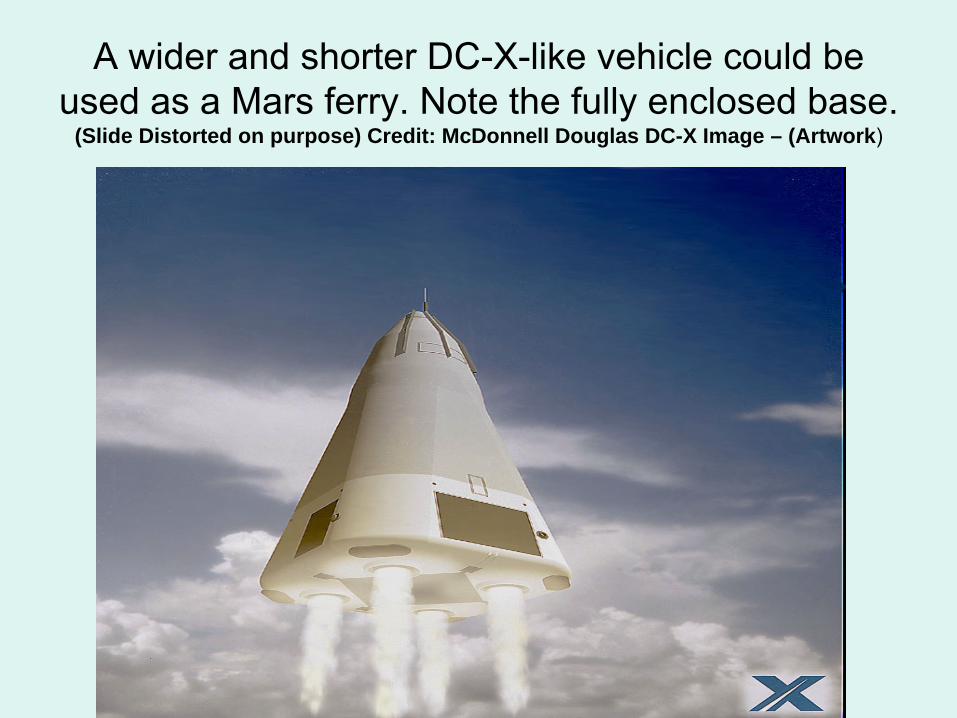
A wider and shorter DC-X-like vehicle could be used as a Mars ferry. Note the fully enclosed base.
(Slide Distorted on purpose) Credit: McDonnell Douglas DC-X Image – (Artwork)
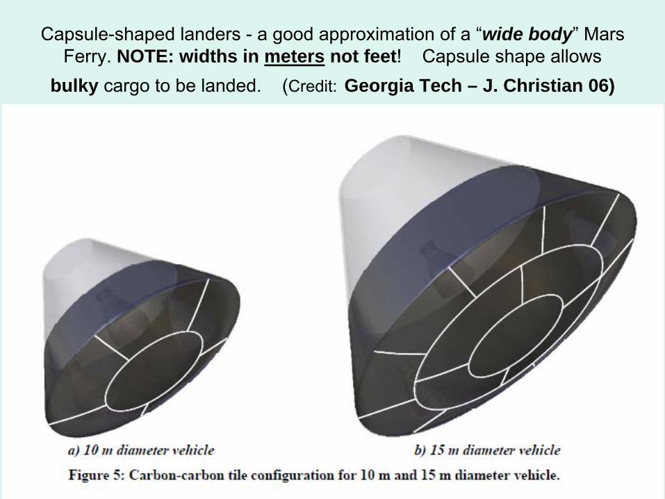
Capsule-shaped landers -
a good approximation of a “wide body” Mars
Ferry. NOTE: widths in meters not feet! Capsule shape allows
bulky cargo to be landed. (Credit:
Georgia Tech – J. Christian 06)
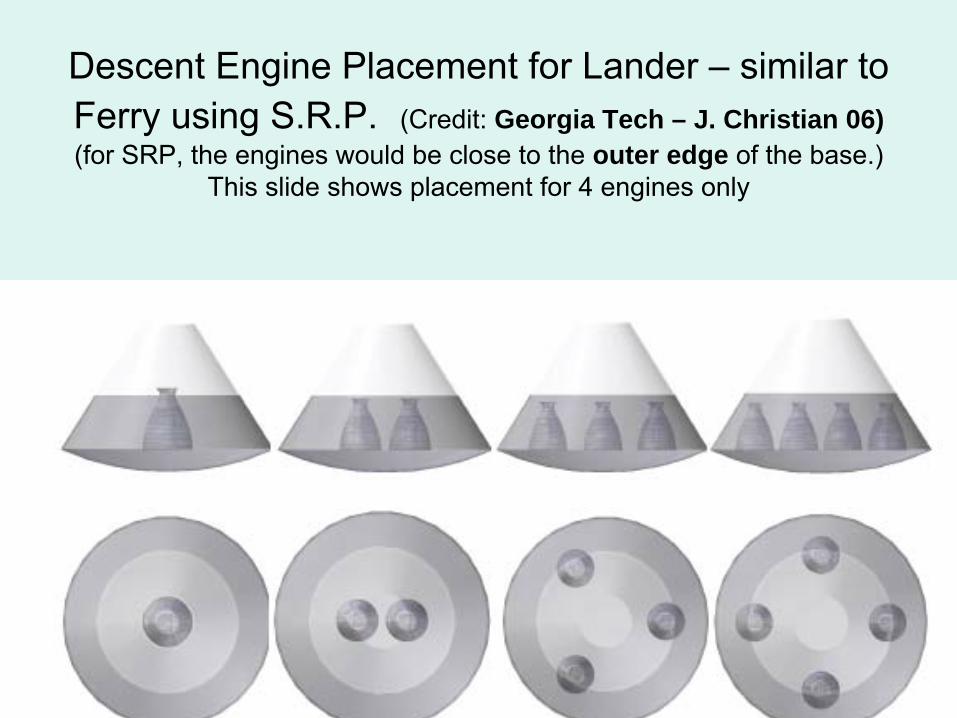
Descent Engine Placement for Lander –
similar to Ferry using S.R.P. (Credit: Georgia Tech – J. Christian 06) (for SRP, the engines would be close to the outer edge of the base.)
This slide shows placement for 4 engines only
Why do we need Mars Ferries?•
Without re-usable vehicles, you have to bring to Mars Orbit from Earth an expendable lander and all of its propellant for every 20 ton cargo you want to use on the surface, greatly increasing mission cost and mass.
•
With Ferries, you can make repeated trips with Cargo Ferries to bring equipment down for the crew to use. You do need a source (ice) of LOX and Hydrogen on the surface (ISRU) and a large propellant supply buffer in orbit (stored in the Propellant Depot) to operate the Ferries continuously. This means the base site must be where ice exists near the surface underground and can be excavated.
•
For early (Mars Direct style) missions to the surface, fuel producing equipment carried by cargo ferries could be offloaded and set up via tele-operations by crew in LMO.
•
This makes a good case for a Mars Orbit only early mission with a crew, and would allow buildup of a very large propellant supply on the surface before crew arrival on the surface.
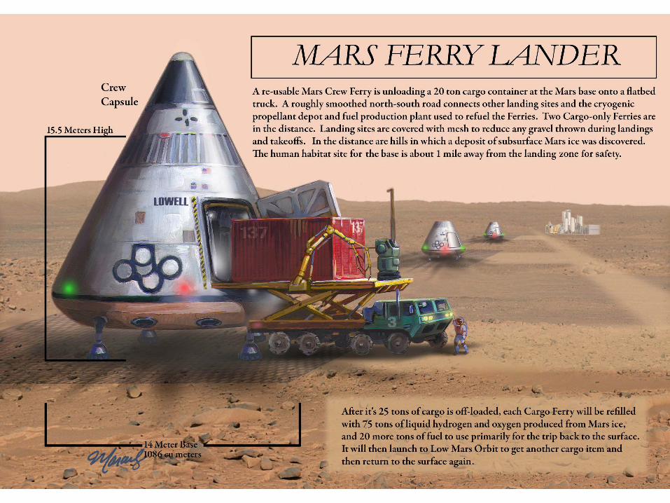
Mars Ferry: Launch Weight - 125 Tonnes•
Both Cargo & Crew designs mass ~ 70 mt at descent and 125 mt at lift off, with 20 tons total ascent payload and 25 tons for descent.
•
Both vehicles have a base heat shield diameter 14 meters wide.•
Both Ferry versions have a cargo bay to hold up to 25 tons of large cargo with cargo bay doors that open on the side below the fuel tanks.
•
Both Ferry versions have oversize tanks that can hold 95 tons of propellant (about 75 tons for ascent, about 15 tons for the subsequent descent, and about 5 tons extra for deposit in the propellant depot. (cargo ferry only)
•
CREW AND CARGO FERRY DIFFERENCES:•
The Crew Ferry has a 5 ton crew cabin / escape capsule on top. It would never separate from the Ferry except in an emergency. The cargo Ferry has
no equivalent capsule on top.•
The Crew Ferry would carry 15 tons of propellants UP as payload in its tanks during a ascent mission, and 20 tons of cargo DOWN during a descent mission.
•
The Cargo Ferry carries (as payload) 20 tons (fuel) UP in its tanks and 25 tons (cargo) DOWN in the cargo bay.
•
Total Ascent and Descent Masses are the same for both Ferries.
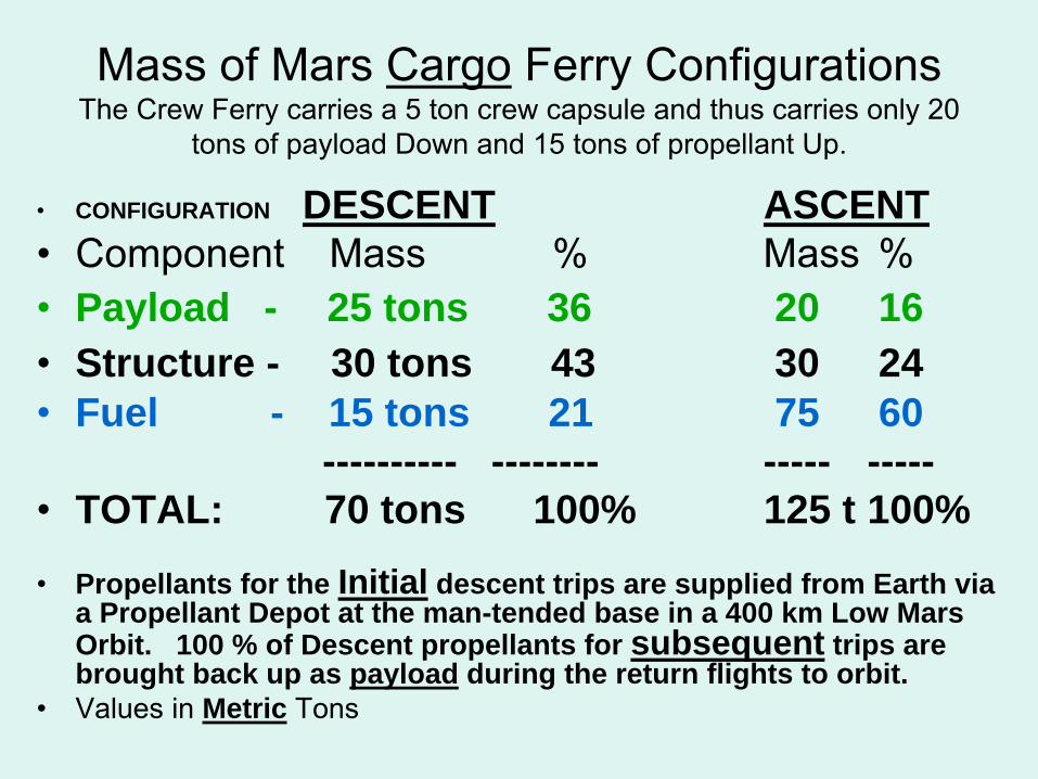
Mass of Mars Cargo
Ferry Configurations The Crew Ferry carries a 5 ton crew capsule and thus carries only 20
tons of payload Down and 15 tons of propellant Up.
•
CONFIGURATION DESCENT ASCENT•
Component Mass
%
Mass
%
•
Payload - 25 tons 36 20 16•
Structure - 30 tons 43 30 24
•
Fuel - 15 tons 21 75 60---------- -------- ----- -----
•
TOTAL: 70 tons 100% 125 t 100%
•
Propellants for the Initial descent trips are supplied from Earth via a Propellant Depot at the man-tended base in a 400 km Low Mars Orbit. 100 % of Descent propellants for subsequent trips are brought back up as payload during the return flights to orbit.
•
Values in Metric Tons
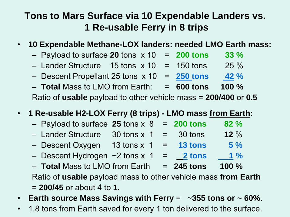
Tons to Mars Surface via 10 Expendable Landers vs. 1 Re-usable Ferry in 8 trips
•
10 Expendable Methane-LOX landers: needed LMO Earth mass:–
Payload to surface 20 tons x 10 = 200 tons 33 %–
Lander Structure 15 tons x 10 = 150 tons
25 %–
Descent Propellant 25 tons x 10 = 250 tons 42 %–
Total Mass to LMO from Earth:
= 600 tons 100 %Ratio of usable payload to other vehicle mass = 200/400 or 0.5
•
1 Re-usable H2-LOX Ferry (8 trips) - LMO mass from Earth:–
Payload to surface 25 tons x 8
= 200 tons 82 % –
Lander Structure 30 tons x 1
= 30 tons
12 % –
Descent Oxygen 13 tons x 1
= 13 tons 5 %–
Descent Hydrogen ~2 tons x 1 = 2 tons 1 %–
Total Mass to LMO from Earth
= 245 tons 100 %Ratio of usable payload mass to other vehicle mass from Earth= 200/45 or about 4 to 1.
•
Earth source Mass Savings with Ferry = ~355 tons or ~ 60%.•
1.8 tons from Earth saved for every 1 ton delivered to the surface.
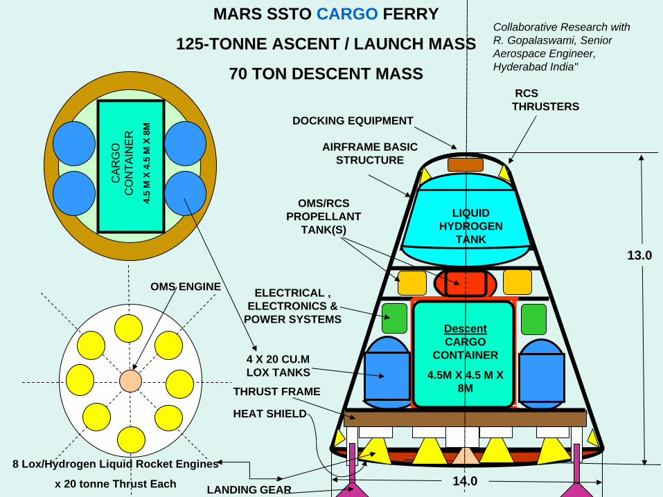
13.0
14.08 Lox/Hydrogen Liquid Rocket Engines
x 20 tonne Thrust Each
Descent CARGO
CONTAINER
4.5M X 4.5 M X 8M
LIQUID HYDROGEN
TANK
4 X 20 CU.M LOX TANKS
CA
RG
OC
ON
TAIN
ER
4.
5 M
X 4
.5 M
X 8
M
OMS/RCS PROPELLANT
TANK(S)
ELECTRICAL , ELECTRONICS &
POWER SYSTEMS
THRUST FRAME
LANDING GEAR
MARS SSTO CARGO FERRY
125-TONNE ASCENT / LAUNCH MASS
70 TON DESCENT MASS
AIRFRAME BASIC STRUCTURE
HEAT SHIELD
RCS THRUSTERS
Collaborative Research with R. Gopalaswami, Senior Aerospace Engineer, Hyderabad India"
OMS ENGINE
DOCKING EQUIPMENT
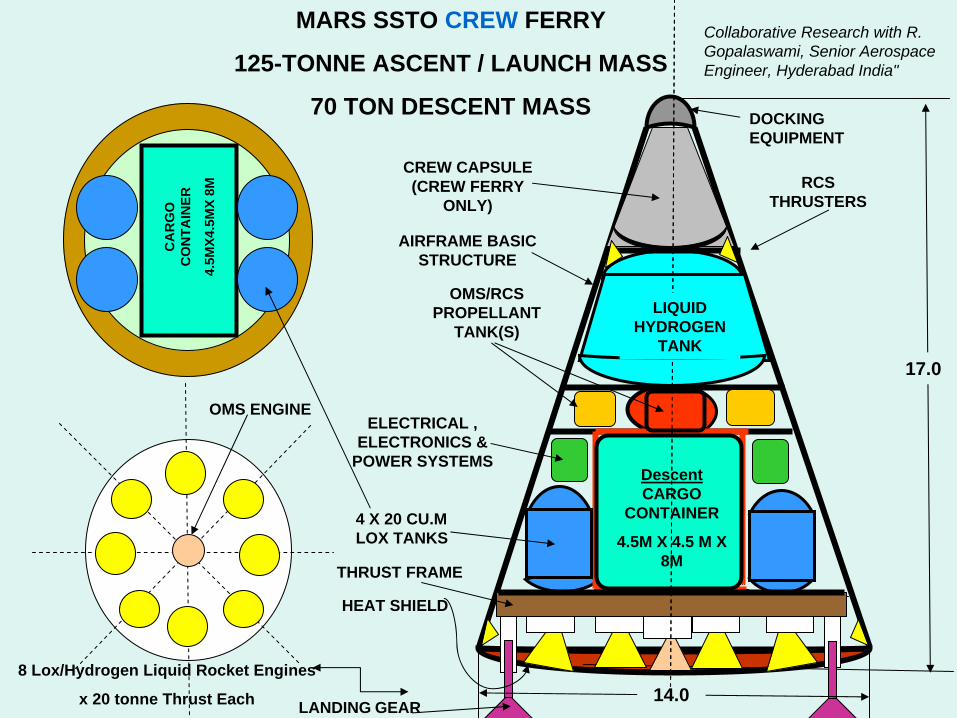
17.0
14.08 Lox/Hydrogen Liquid Rocket Engines
x 20 tonne Thrust Each
Descent CARGO
CONTAINER
4.5M X 4.5 M X 8M
LIQUID HYDROGEN
TANK
4 X 20 CU.M LOX TANKS
CA
RG
O
CO
NTA
INER
4.5M
X4.5
MX
8M RCS THRUSTERS
OMS/RCS PROPELLANT
TANK(S)
CREW CAPSULE (CREW FERRY
ONLY)
ELECTRICAL , ELECTRONICS &
POWER SYSTEMS
THRUST FRAME
LANDING GEAR
MARS SSTO CREW FERRY
125-TONNE ASCENT / LAUNCH MASS
70 TON DESCENT MASS
AIRFRAME BASIC STRUCTURE
HEAT SHIELD
Collaborative Research with R. Gopalaswami, Senior Aerospace Engineer, Hyderabad India"
OMS ENGINE
DOCKING EQUIPMENT
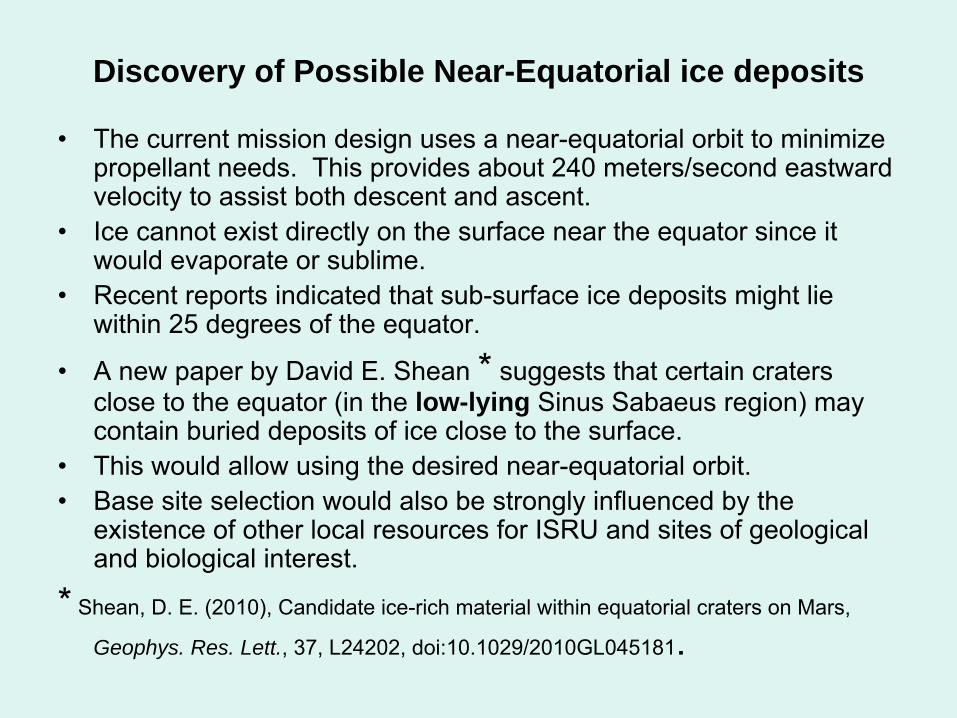
Discovery of Possible Near-Equatorial ice deposits
•
The current mission design uses a near-equatorial orbit to minimize propellant needs. This provides about 240 meters/second eastward velocity to assist both descent and ascent.
•
Ice cannot exist directly on the surface near the equator since it would evaporate or sublime.
•
Recent reports indicated that sub-surface ice deposits might lie within 25 degrees of the equator.
•
A new paper by David E. Shean
*
suggests that certain craters close to the equator (in the low-lying Sinus Sabaeus
region) may contain buried deposits of ice close to the surface.
•
This would allow using the desired near-equatorial orbit.•
Base site selection would also be strongly influenced by the existence of other local resources for ISRU and sites of geological and biological interest.
*
Shean, D. E. (2010), Candidate ice-rich material within equatorial craters on Mars,
Geophys. Res. Lett., 37, L24202, doi:10.1029/2010GL045181
.
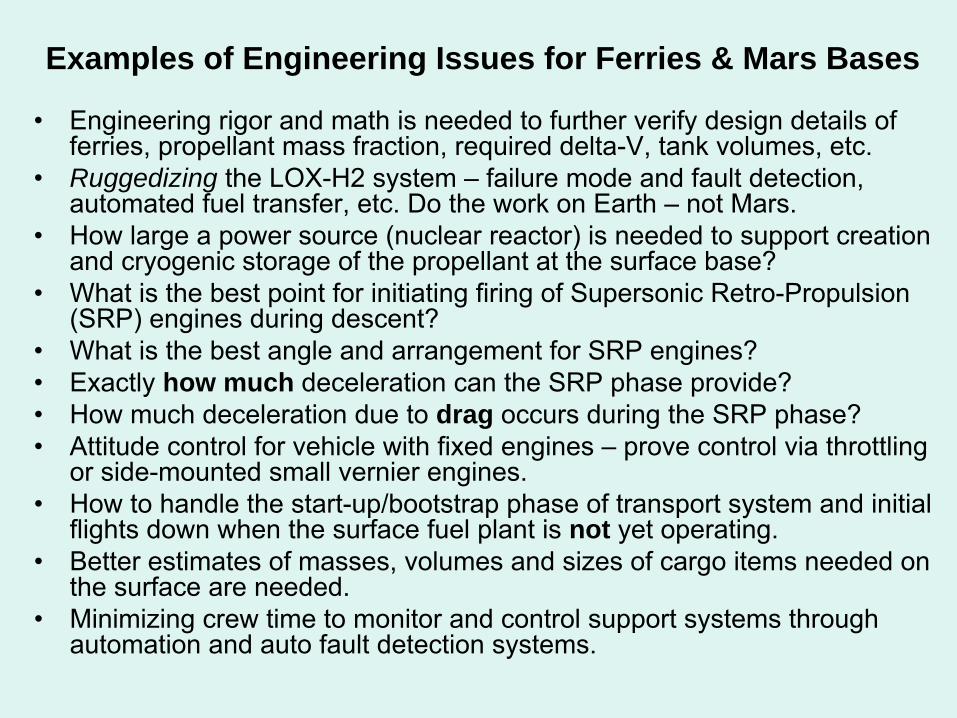
Examples of Engineering Issues for Ferries & Mars Bases
•
Engineering rigor and math is needed to further verify design details of ferries, propellant mass fraction, required delta-V, tank volumes, etc.
•
Ruggedizing the LOX-H2 system –
failure mode and fault detection, automated fuel transfer, etc. Do the work on Earth –
not Mars.•
How large a power source (nuclear reactor) is needed to support creation and cryogenic storage of the propellant at the surface base?
•
What is the best point for initiating firing of Supersonic Retro-Propulsion (SRP) engines during descent?
•
What is the best angle and arrangement for SRP engines?•
Exactly how much deceleration can the SRP phase provide?•
How much deceleration due to drag occurs during the SRP phase?•
Attitude control for vehicle with fixed engines –
prove control via throttling or side-mounted small vernier
engines. •
How to handle the start-up/bootstrap phase of transport system and initial flights down when the surface fuel plant is not yet operating.
•
Better estimates of masses, volumes and sizes of cargo items needed on the surface are needed.
•
Minimizing crew time to monitor and control support systems through automation and auto fault detection systems.
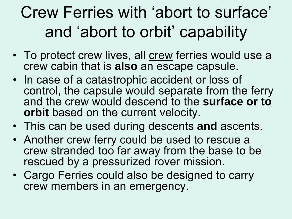
Crew Ferries with ‘abort to surface’ and ‘abort to orbit’
capability
•
To protect crew lives, all crew
ferries would use a crew cabin that is also an escape capsule.
•
In case of a catastrophic accident or loss of control, the capsule would separate from the ferry and the crew would descend to the surface or to orbit based on the current velocity.
•
This can be used during descents and ascents.•
Another crew ferry could be used to rescue a crew stranded too far away from the base to be rescued by a pressurized rover mission.
•
Cargo Ferries could also be designed to carry crew members in an emergency.
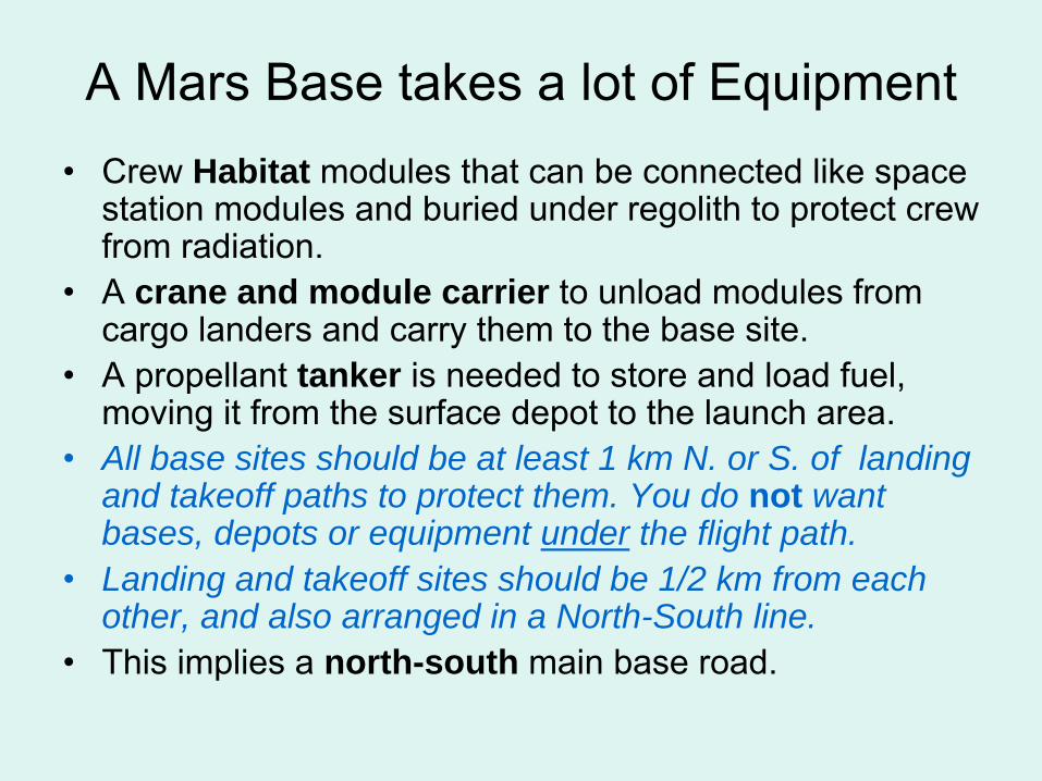
A Mars Base takes a lot of Equipment•
Crew Habitat modules that can be connected like space station modules and buried under regolith to protect crew from radiation.
•
A crane and module carrier to unload modules from cargo landers and carry them to the base site.
•
A propellant tanker is needed to store and load fuel, moving it from the surface depot to the launch area.
•
All base sites should be at least 1 km N. or S. of landing and takeoff paths to protect them. You do not want bases, depots or equipment under the flight path.
•
Landing and takeoff sites should be 1/2 km from each other, and also arranged in a North-South line.
•
This implies a north-south main base road.
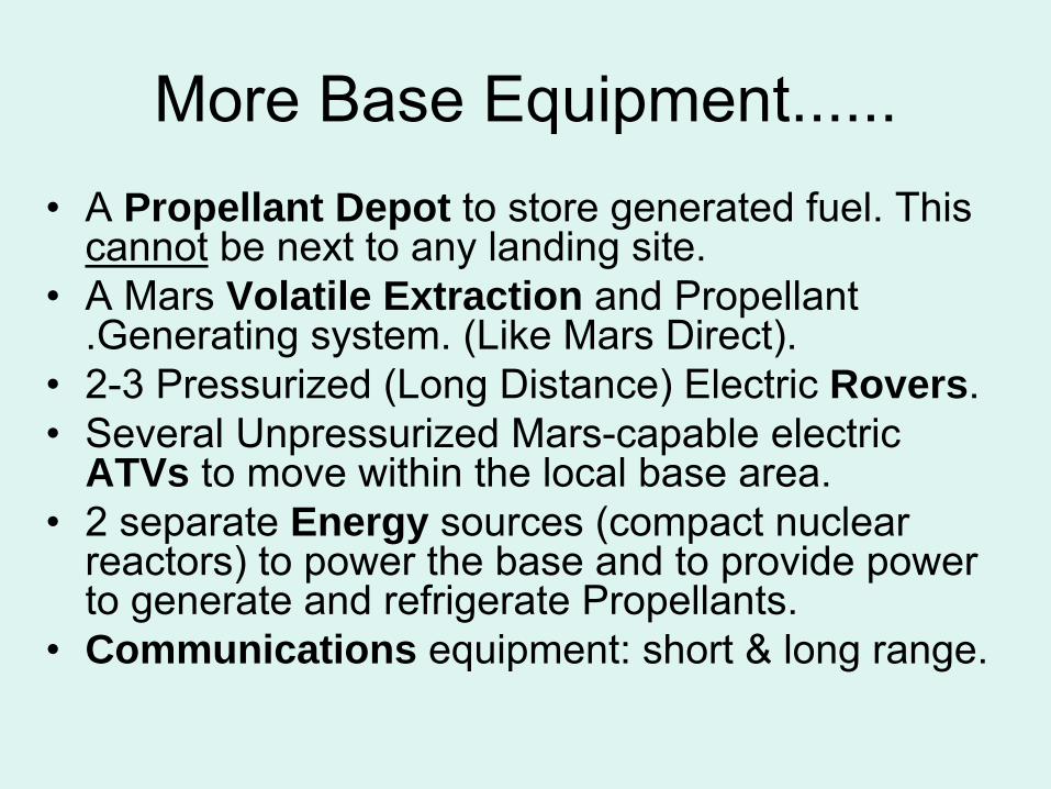
More Base Equipment......•
A Propellant Depot to store generated fuel. This cannot
be next to any landing site.
•
A Mars Volatile Extraction and Propellant .Generating system. (Like Mars Direct).
•
2-3 Pressurized (Long Distance) Electric Rovers.•
Several Unpressurized Mars-capable electric ATVs to move within the local base area.
•
2 separate Energy sources (compact nuclear reactors) to power the base and to provide power to generate and refrigerate Propellants.
•
Communications equipment: short & long range.
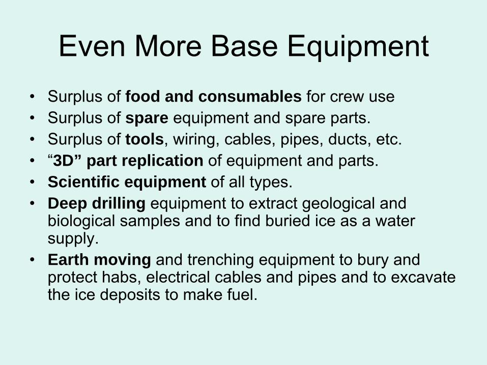
Even More Base Equipment•
Surplus of food and consumables for crew use
•
Surplus of spare equipment and spare parts.•
Surplus of
tools, wiring, cables, pipes, ducts, etc.
•
“3D” part replication of equipment and parts.•
Scientific equipment of all types.
•
Deep drilling equipment to extract geological and biological samples and to find buried ice as a water supply.
•
Earth moving and trenching equipment to bury and protect habs, electrical cables and pipes and to excavate the ice deposits to make fuel.
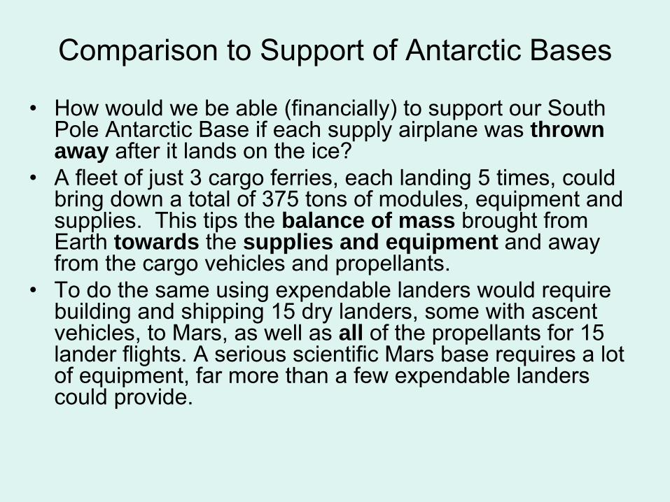
Comparison to Support of Antarctic Bases
•
How would we be able (financially) to support our South Pole Antarctic Base if each supply airplane was thrown away after it lands on the ice?
•
A fleet of just 3 cargo ferries, each landing 5 times, could bring down a total of 375 tons of modules, equipment and supplies. This tips the balance of mass brought from Earth towards the supplies and equipment and away from the cargo vehicles and propellants.
•
To do the same using expendable landers would require building and shipping 15 dry landers, some with ascent vehicles, to Mars, as well as all of the propellants for 15 lander flights. A serious scientific Mars base requires a lot of equipment, far more than a few expendable landers could provide.
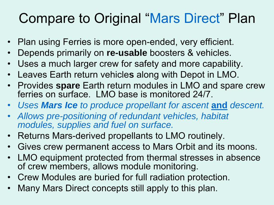
Compare to Original “Mars Direct” Plan•
Plan using Ferries is more open-ended, very efficient.
•
Depends primarily on re-usable boosters & vehicles.•
Uses a much larger crew for safety and more capability.
•
Leaves Earth return vehicles along with Depot in LMO. •
Provides spare Earth return modules in LMO and spare crew ferries on surface. LMO base is monitored 24/7.
•
Uses Mars Ice to produce propellant for ascent and descent.•
Allows pre-positioning of redundant vehicles, habitat modules, supplies and fuel on surface.
•
Returns Mars-derived propellants to LMO routinely.•
Gives crew permanent access to Mars Orbit and its moons.
•
LMO equipment protected from thermal stresses in absence of crew members, allows module monitoring.
•
Crew Modules are buried for full radiation protection.•
Many Mars Direct concepts still apply to this plan.
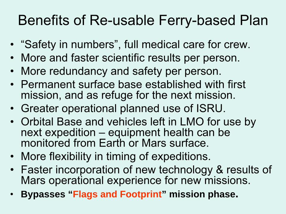
Benefits of Re-usable Ferry-based Plan•
“Safety in numbers”, full medical care for crew.
•
More and faster scientific results per person.•
More redundancy and safety per person.
•
Permanent surface base established with first mission, and as refuge for the next mission.
•
Greater operational planned use of ISRU.•
Orbital Base and vehicles left in LMO for use by next expedition –
equipment health can be
monitored from Earth or Mars surface.•
More flexibility in timing of expeditions.
•
Faster incorporation of new technology & results of Mars operational experience for new missions.
•
Bypasses “Flags and Footprint” mission phase.
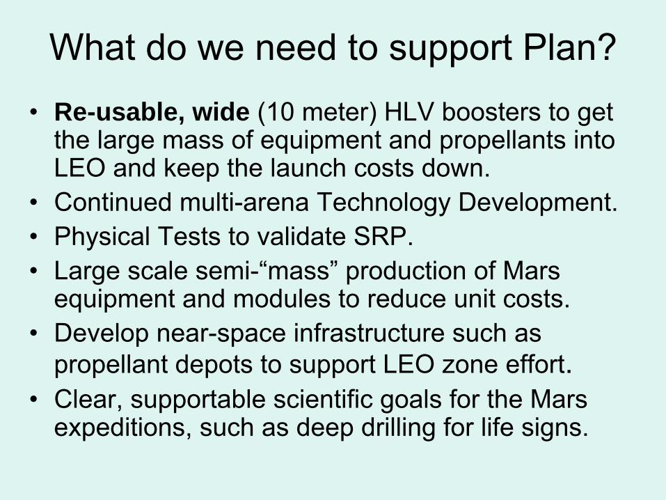
What do we need to support Plan?•
Re-usable, wide (10 meter) HLV boosters to get the large mass of equipment and propellants into LEO and keep the launch costs down.
•
Continued multi-arena Technology Development.•
Physical Tests to validate SRP.
•
Large scale semi-“mass”
production of Mars equipment and modules to reduce unit costs.
•
Develop near-space infrastructure such as propellant depots to support LEO zone effort.
•
Clear, supportable scientific goals for the Mars expeditions, such as deep drilling for life signs.
Lets Keep
Going to Mars
•
Our objective is to create a capability for continuing Manned Mars exploration.
•
Let us use the time until the First Mars Expedition making sure that once we go there, we can afford to keep going there.
•
Assuming the first expedition would take place after 2030, we have over 20 years to create Re-usable space vehicles.
•
Surely that is time enough to do it.
Engineering Data & Graphs
•
Values shown are current, and
will change as improvements are made to this concept.
•
NOTE: Some graphs and tables do not account for the gravitational acceleration during the period in the transfer orbit after the de-orbit burn and before start of entry. This is reflected in a difference in total descent delta-V requirements for the Ferries in those graphs.
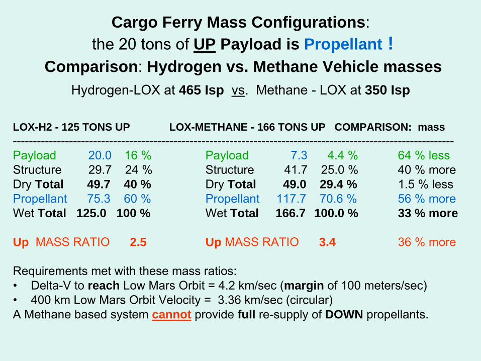
Cargo Ferry Mass Configurations: the 20 tons of UP Payload is Propellant !
Comparison: Hydrogen vs. Methane Vehicle masses Hydrogen-LOX at 465 Isp vs. Methane -
LOX at 350 Isp
LOX-H2 - 125 TONS UP LOX-METHANE - 166 TONS UP COMPARISON: mass--------------------------------------------------------------------------------------------------------------Payload 20.0
16 %
Payload 7.3
4.4 %
64 % lessStructure 29.7 24 % Structure 41.7 25.0 %
40 % more Dry Total 49.7 40 % Dry Total 49.0 29.4 % 1.5 % lessPropellant 75.3 60 %
Propellant 117.7 70.6 %
56 % moreWet Total 125.0 100 % Wet Total 166.7 100.0 % 33 % more
Up MASS RATIO 2.5 Up MASS RATIO 3.4 36 % more
Requirements met with these mass ratios:•
Delta-V to reach Low Mars Orbit = 4.2 km/sec (margin of 100 meters/sec)•
400 km Low Mars Orbit Velocity = 3.36 km/sec (circular)A Methane based system cannot provide full re-supply of DOWN propellants.
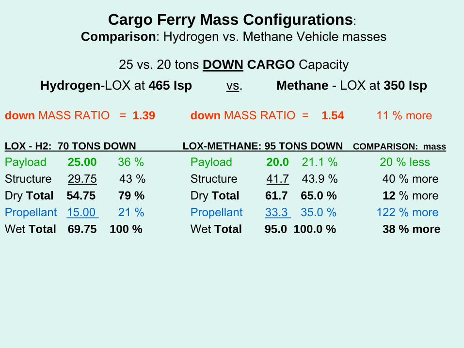
Cargo Ferry Mass Configurations:
Comparison: Hydrogen vs. Methane Vehicle masses
25 vs. 20 tons DOWN CARGO Capacity
Hydrogen-LOX at 465 Isp vs.
Methane - LOX at 350 Isp
down MASS RATIO = 1.39 down MASS RATIO = 1.54 11 % more
LOX - H2: 70 TONS DOWN LOX-METHANE: 95 TONS DOWN COMPARISON: mass
Payload 25.00 36 %
Payload 20.0 21.1 % 20 % lessStructure 29.75
43 % Structure 41.7
43.9 %
40 % more Dry Total 54.75 79 % Dry Total 61.7 65.0 % 12 % morePropellant 15.00 21 %
Propellant 33.3 35.0 %
122 % moreWet Total 69.75 100 % Wet Total 95.0 100.0 % 38 % more
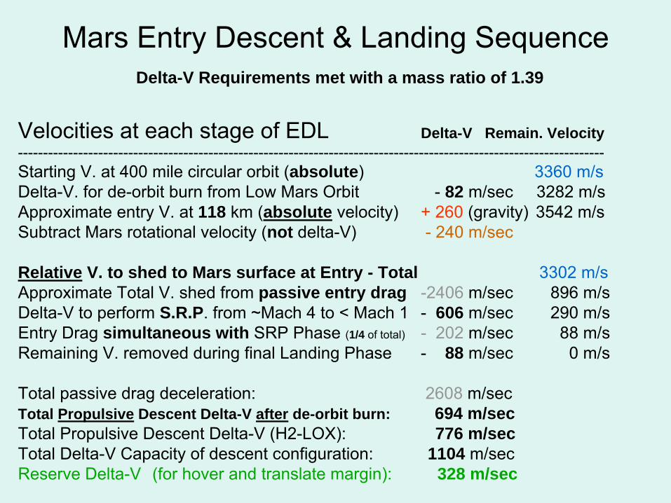
Mars Entry Descent & Landing Sequence Delta-V Requirements met with a mass ratio of 1.39
Velocities at each stage of EDL
Delta-V Remain. Velocity---------------------------------------------------------------------------------------------------------------------Starting V. at 400 mile circular orbit (absolute)
3360 m/sDelta-V. for de-orbit burn from Low Mars Orbit -
82 m/sec 3282 m/sApproximate entry V. at 118 km (absolute velocity)
+ 260
(gravity) 3542 m/sSubtract Mars rotational velocity (not delta-V)
-
240 m/sec
Relative V. to shed to Mars surface at Entry - Total 3302 m/sApproximate Total V. shed from passive entry drag -2406
m/sec 896 m/sDelta-V to perform S.R.P. from ~Mach 4 to < Mach 1
-
606 m/sec 290 m/sEntry Drag simultaneous with SRP Phase (1/4 of total)
-
202
m/sec 88 m/sRemaining V. removed during final Landing Phase -
88 m/sec 0 m/s
Total passive drag deceleration:
2608
m/secTotal Propulsive Descent Delta-V after de-orbit burn: 694 m/secTotal Propulsive Descent Delta-V (H2-LOX):
776 m/secTotal Delta-V Capacity of descent configuration: 1104 m/secReserve Delta-V
(for hover and translate margin):
328 m/sec
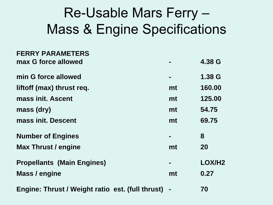
Re-Usable Mars Ferry – Mass & Engine Specifications
FERRY PARAMETERS max G force allowed - 4.38 G
min G force allowed - 1.38 Gliftoff (max) thrust req. mt 160.00mass init. Ascent mt 125.00mass (dry) mt 54.75mass init. Descent mt 69.75
Number of Engines - 8Max Thrust / engine mt 20
Propellants (Main Engines) - LOX/H2Mass / engine mt 0.27
Engine: Thrust / Weight ratio est. (full thrust) - 70
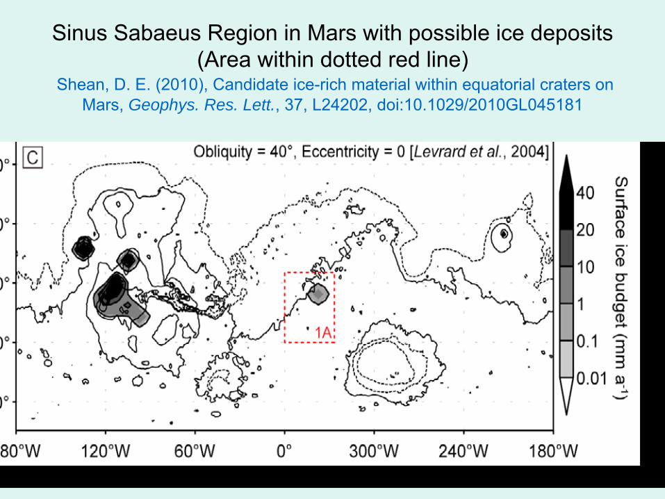
Sinus Sabaeus
Region in Mars with possible ice deposits (Area within dotted red line)
Shean, D. E. (2010), Candidate ice-rich material within equatorial craters on Mars, Geophys. Res. Lett., 37, L24202, doi:10.1029/2010GL045181
2.5
6.57.5
12.0
17.0
18.0
14.0
2.0
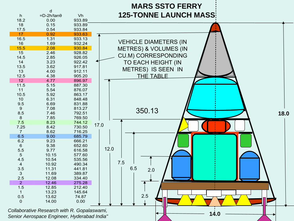
h d
=D-2h/tanθ Vh 18.2 0.00 933.89 18 0.15 933.89
17.5 0.54 933.84 17 0.92 933.63
16.5 1.31 933.13 16 1.69 932.24
15.5 2.08 930.84 15 2.46 928.82
14.5 2.85 926.05 14 3.23 922.42
13.5 3.62 917.81 13 4.00 912.11
12.5 4.38 905.20 12 4.77 896.97
11.5 5.15 887.30 11 5.54 876.07
10.5 5.92 863.17 10 6.31 848.48 9.5 6.69 831.88 9 7.08 813.27
8.5 7.46 792.51 8 7.85 769.50
7.5 8.23 744.12 7.25 8.42 730.50
7 8.62 716.25 6.5 9.00 685.79 6.2 9.23 666.21 6 9.38 652.60
5.5 9.77 616.58 5 10.15 577.60
4.5 10.54 535.56 4 10.92 490.34
3.5 11.31 441.81 3 11.69 389.87
2.5 12.08 334.40 2 12.46 275.28
1.5 12.85 212.40 1 13.23 145.64
0.5 13.62 74.87 0 14.00 0.00
MARS SSTO FERRY125-TONNE LAUNCH MASS
VEHICLE DIAMETERS (IN METRES) & VOLUMES (IN CU.M) CORRESPONDING
TO EACH HEIGHT (IN METRES) IS SEEN IN
THE TABLE
350.13
Collaborative Research with R. Gopalaswami, Senior Aerospace Engineer, Hyderabad India"
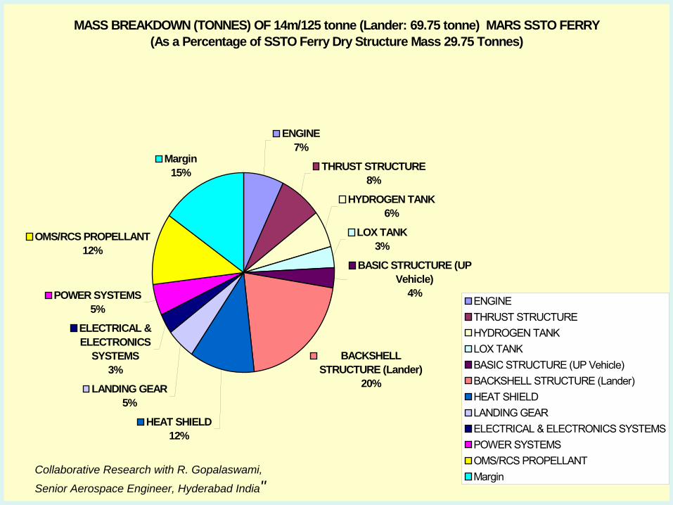
MASS BREAKDOWN (TONNES) OF 14m/125 tonne (Lander: 69.75 tonne) MARS SSTO FERRY(As a Percentage of SSTO Ferry Dry Structure Mass 29.75 Tonnes)
ENGINE7%
THRUST STRUCTURE8%
HYDROGEN TANK6%
LOX TANK3%
BASIC STRUCTURE (UP Vehicle)
4%
BACKSHELL STRUCTURE (Lander)
20%
HEAT SHIELD12%
LANDING GEAR5%
ELECTRICAL & ELECTRONICS
SYSTEMS3%
POWER SYSTEMS5%
OMS/RCS PROPELLANT12%
Margin 15%
ENGINETHRUST STRUCTUREHYDROGEN TANKLOX TANKBASIC STRUCTURE (UP Vehicle)BACKSHELL STRUCTURE (Lander)HEAT SHIELDLANDING GEARELECTRICAL & ELECTRONICS SYSTEMSPOWER SYSTEMSOMS/RCS PROPELLANTMargin Collaborative Research with R. Gopalaswami,
Senior Aerospace Engineer, Hyderabad India"
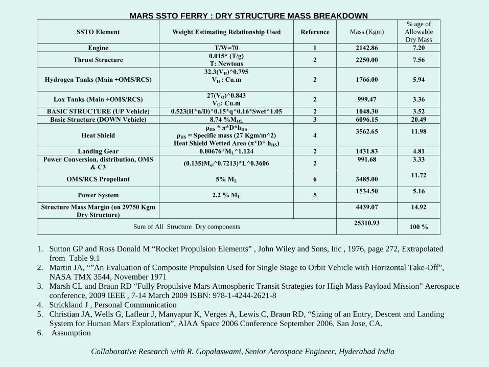
MARS SSTO FERRY : DRY STRUCTURE MASS BREAKDOWN
SSTO Element Weight Estimating Relationship Used Reference Mass (Kgm) % age of
Allowable Dry Mass
Engine T/W=70 1 2142.86 7.20
Thrust Structure 0.015* (T/g) T: Newtons 2 2250.00 7.56
Hydrogen Tanks (Main +OMS/RCS) 32.3(VH)^0.795
VH : Cu.m
2 1766.00 5.94
Lox Tanks (Main +OMS/RCS) 27(VO)^0.843 VO: Cu.m 2 999.47 3.36
BASIC STRUCTURE (UP Vehicle) 0.523(H*n/D)^0.15*q^0.16*Swet^1.05 2 1048.30 3.52 Basic Structure (DOWN Vehicle) 8.74 %MOL 3 6096.15 20.49
Heat Shield ρHS * π*D*hHS
ρHS = Specific mass (27 Kgm/m^2) Heat Shield Wetted Area (π*D* hHS)
4 3562.65
11.98
Landing Gear 0.00676*ML^1.124 2 1431.83 4.81 Power Conversion, distribution, OMS
& C3 (0.135)Mof^0.7213)*L^0.3606 2 991.68
3.33
OMS/RCS Propellant 5% ML 6 3485.00 11.72
Power System 2.2 % ML 5 1534.50
5.16
Structure Mass Margin (on 29750 Kgm Dry Structure) 4439.07
14.92
Sum of All Structure Dry components 25310.93 100 %
1. Sutton GP and Ross Donald M “Rocket Propulsion Elements” , John Wiley and Sons, Inc , 1976, page 272, Extrapolated
from Table 9.1 2. Martin JA, “”An Evaluation of Composite Propulsion Used for Single Stage to Orbit Vehicle with Horizontal Take-Off”,
NASA TMX 3544, November 1971 3. Marsh CL and Braun RD “Fully Propulsive Mars Atmospheric Transit Strategies for High Mass Payload Mission” Aerospace
conference, 2009 IEEE , 7-14 March 2009 ISBN: 978-1-4244-2621-8 4. Strickland J , Personal Communication 5. Christian JA, Wells G, Lafleur J, Manyapur K, Verges A, Lewis C, Braun RD, “Sizing of an Entry, Descent and Landing
System for Human Mars Exploration”, AIAA Space 2006 Conference September 2006, San Jose, CA. 6. Assumption
Collaborative Research with R. Gopalaswami, Senior Aerospace Engineer, Hyderabad India
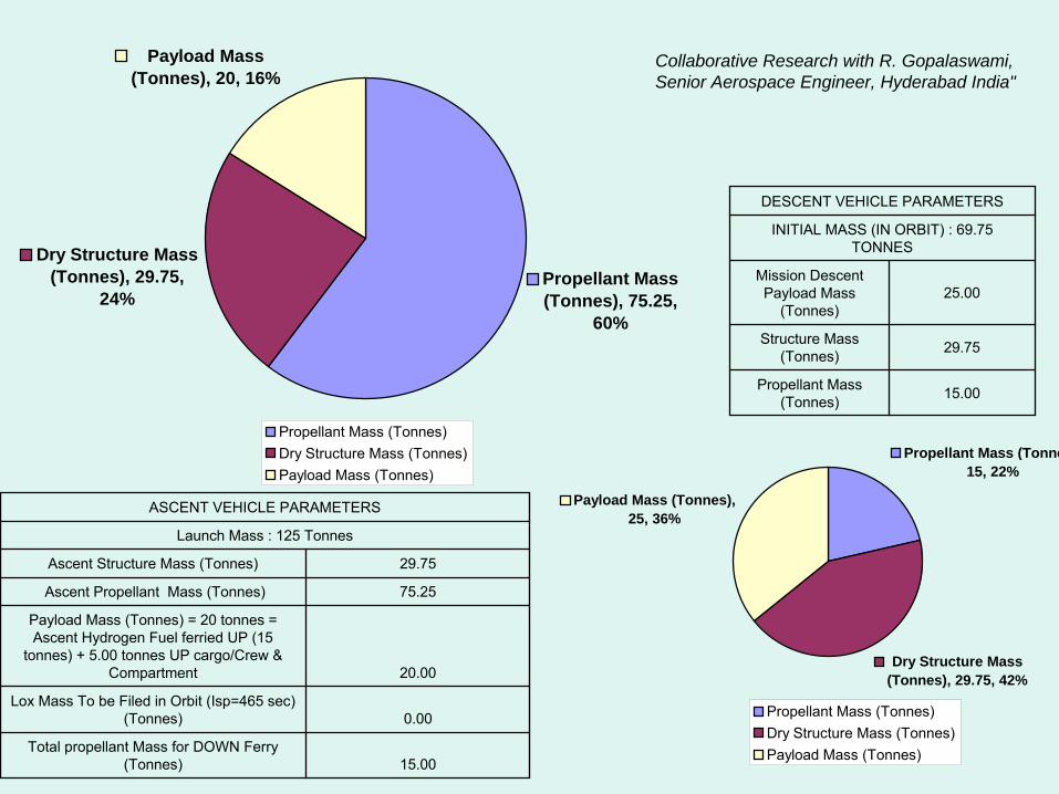
DESCENT VEHICLE PARAMETERS
INITIAL MASS (IN ORBIT) : 69.75 TONNES
Mission Descent Payload Mass
(Tonnes)25.00
Structure Mass (Tonnes) 29.75
Propellant Mass (Tonnes) 15.00
ASCENT VEHICLE PARAMETERS
Launch Mass : 125 Tonnes
Ascent Structure Mass (Tonnes) 29.75
Ascent Propellant Mass (Tonnes) 75.25
Payload Mass (Tonnes) = 20 tonnes = Ascent Hydrogen Fuel ferried UP (15
tonnes) + 5.00 tonnes UP cargo/Crew & Compartment 20.00
Lox Mass To be Filed in Orbit (Isp=465 sec) (Tonnes) 0.00
Total propellant Mass for DOWN Ferry (Tonnes) 15.00
Propellant Mass (Tonnes), 75.25,
60%
Dry Structure Mass (Tonnes), 29.75,
24%
Payload Mass (Tonnes), 20, 16%
Propellant Mass (Tonnes)Dry Structure Mass (Tonnes)Payload Mass (Tonnes)
Propellant Mass (Tonne15, 22%
Dry Structure Mass (Tonnes), 29.75, 42%
Payload Mass (Tonnes), 25, 36%
Propellant Mass (Tonnes)Dry Structure Mass (Tonnes)Payload Mass (Tonnes)
Collaborative Research with R. Gopalaswami, Senior Aerospace Engineer, Hyderabad India"
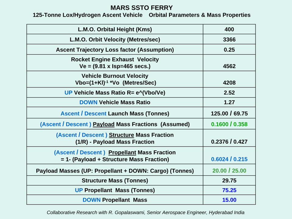
MARS SSTO FERRY125-Tonne Lox/Hydrogen Ascent Vehicle Orbital Parameters & Mass Properties
L.M.O. Orbital Height (Kms) 400
L.M.O. Orbit Velocity (Metres/sec) 3366
Ascent Trajectory Loss factor (Assumption) 0.25Rocket Engine Exhaust Velocity
Ve = (9.81 x Isp=465 secs.) 4562Vehicle Burnout Velocity
Vbo=(1+Kl)-1 *Vo (Metres/Sec) 4208
UP Vehicle Mass Ratio R= e^(Vbo/Ve) 2.52DOWN Vehicle Mass Ratio 1.27
Ascent / Descent Launch Mass (Tonnes) 125.00 / 69.75
(Ascent / Descent ) Payload Mass Fractions (Assumed) 0.1600 / 0.358
(Ascent / Descent ) Structure Mass Fraction (1/R) - Payload Mass Fraction 0.2376 / 0.427
(Ascent / Descent ) Propellant Mass Fraction = 1- (Payload + Structure Mass Fraction) 0.6024 / 0.215
Payload Masses (UP: Propellant + DOWN: Cargo) (Tonnes) 20.00 / 25.00
Structure Mass (Tonnes) 29.75UP Propellant Mass (Tonnes) 75.25
DOWN Propellant Mass 15.00
Collaborative Research with R. Gopalaswami, Senior Aerospace Engineer, Hyderabad India
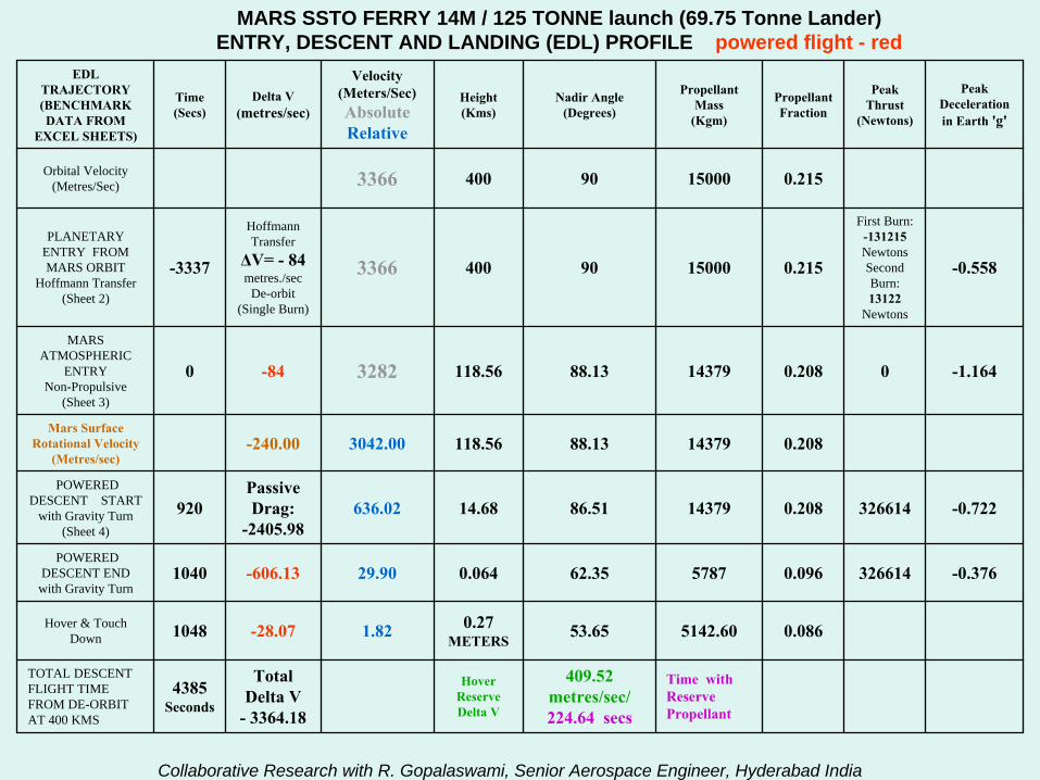
MARS SSTO FERRY 14M / 125 TONNE launch (69.75 Tonne Lander)ENTRY, DESCENT AND LANDING (EDL) PROFILE powered flight - red
EDL TRAJECTORY (BENCHMARK DATA FROM
EXCEL SHEETS)
Time (Secs)
Delta V (metres/sec)
Velocity (Meters/Sec)AbsoluteRelative
Height (Kms)
Nadir Angle (Degrees)
Propellant Mass
(Kgm)
Propellant Fraction
Peak Thrust
(Newtons)
Peak Deceleration in Earth 'g'
Orbital Velocity (Metres/Sec) 3366 400 90 15000 0.215
PLANETARY ENTRY FROM MARS ORBIT
Hoffmann Transfer (Sheet 2)
-3337
Hoffmann Transfer
ΔV= -
84
metres./sec De-orbit
(Single Burn)
3366 400 90 15000 0.215
First Burn: -131215
Newtons Second Burn: 13122
Newtons
-0.558
MARS ATMOSPHERIC
ENTRY Non-Propulsive
(Sheet 3)
0 -84 3282 118.56 88.13 14379 0.208 0 -1.164
Mars Surface Rotational Velocity
(Metres/sec) -240.00 3042.00 118.56 88.13 14379 0.208
POWERED DESCENT START
with Gravity Turn (Sheet 4)
920Passive Drag:
-2405.98636.02 14.68 86.51 14379 0.208 326614 -0.722
POWERED DESCENT END with Gravity Turn
1040 -606.13 29.90 0.064 62.35 5787 0.096 326614 -0.376
Hover & Touch Down 1048 -28.07 1.82 0.27
METERS 53.65 5142.60 0.086
TOTAL DESCENT FLIGHT TIME FROM DE-ORBIT AT 400 KMS
4385 Seconds
Total Delta V
-
3364.18
Hover Reserve Delta V
409.52 metres/sec/ 224.64 secs
Time with Reserve Propellant
Collaborative Research with R. Gopalaswami, Senior Aerospace Engineer, Hyderabad India
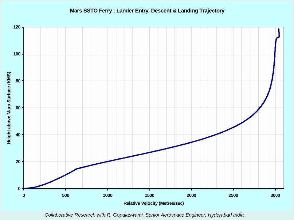
Mars SSTO Ferry : Lander Entry, Descent & Landing Trajectory
0
20
40
60
80
100
120
0 500 1000 1500 2000 2500 3000
Relative Velocity (Metres/sec)
Hei
ght a
bove
Mar
s Su
rfac
e (K
MS)
Collaborative Research with R. Gopalaswami, Senior Aerospace Engineer, Hyderabad India
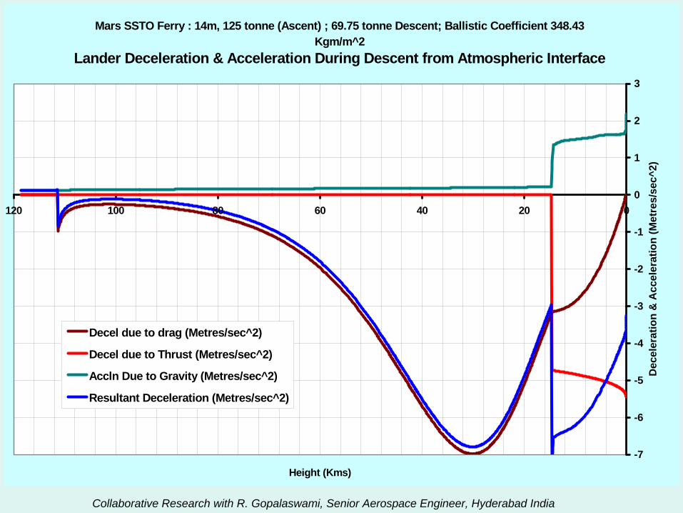
Mars SSTO Ferry : 14m, 125 tonne (Ascent) ; 69.75 tonne Descent; Ballistic Coefficient 348.43 Kgm/m^2
Lander Deceleration & Acceleration During Descent from Atmospheric Interface
-7
-6
-5
-4
-3
-2
-1
0
1
2
3
020406080100120
Height (Kms)
Dec
eler
atio
n &
Acc
eler
atio
n (M
etre
s/se
c^2)
Decel due to drag (Metres/sec^2)
Decel due to Thrust (Metres/sec^2)
Accln Due to Gravity (Metres/sec^2)
Resultant Deceleration (Metres/sec^2)
Collaborative Research with R. Gopalaswami, Senior Aerospace Engineer, Hyderabad India
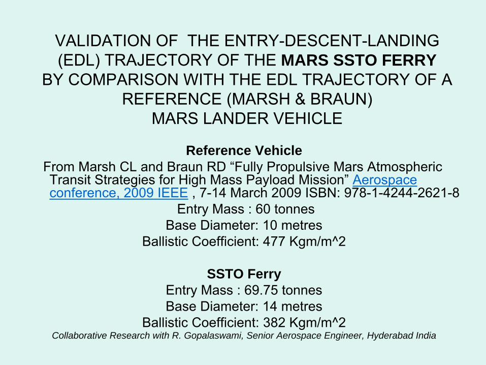
VALIDATION OF THE ENTRY-DESCENT-LANDING (EDL) TRAJECTORY OF THE MARS SSTO FERRY
BY COMPARISON WITH THE EDL TRAJECTORY OF A REFERENCE (MARSH & BRAUN)
MARS LANDER VEHICLE
Reference VehicleFrom Marsh CL and Braun RD “Fully Propulsive Mars Atmospheric Transit Strategies for High Mass Payload Mission”
Aerospace conference, 2009 IEEE
, 7-14 March 2009 ISBN: 978-1-4244-2621-8Entry Mass : 60 tonnes
Base Diameter: 10 metresBallistic Coefficient: 477 Kgm/m^2
SSTO FerryEntry Mass : 69.75 tonnesBase Diameter: 14 metres
Ballistic Coefficient: 382 Kgm/m^2Collaborative Research with R. Gopalaswami, Senior Aerospace Engineer, Hyderabad India
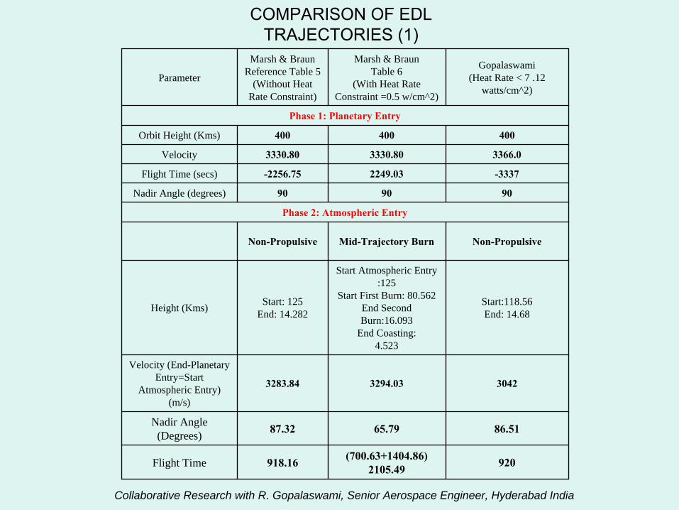
COMPARISON OF EDL TRAJECTORIES (1)
Parameter
Marsh & BraunReference Table 5
(Without Heat Rate Constraint)
Marsh & BraunTable 6
(With Heat Rate Constraint =0.5 w/cm^2)
Gopalaswami(Heat Rate < 7 .12
watts/cm^2)
Phase 1: Planetary Entry
Orbit Height (Kms) 400 400 400
Velocity 3330.80 3330.80 3366.0
Flight Time (secs) -2256.75 2249.03 -3337
Nadir Angle (degrees) 90 90 90
Phase 2: Atmospheric Entry
Non-Propulsive Mid-Trajectory Burn Non-Propulsive
Height (Kms) Start: 125End: 14.282
Start Atmospheric Entry :125
Start First Burn: 80.562End Second Burn:16.093
End Coasting:4.523
Start:118.56End: 14.68
Velocity (End-Planetary Entry=Start
Atmospheric Entry) (m/s)
3283.84 3294.03 3042
Nadir Angle (Degrees) 87.32 65.79 86.51
Flight Time 918.16 (700.63+1404.86)2105.49 920
Collaborative Research with R. Gopalaswami, Senior Aerospace Engineer, Hyderabad India
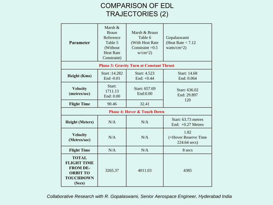
COMPARISON OF EDL TRAJECTORIES (2)
Parameter
Marsh & Braun
Reference Table 5
(Without Heat Rate
Constraint)
Marsh & BraunTable 6
(With Heat Rate Constraint =0.5
w/cm^2)
Gopalaswami(Heat Rate < 7.12 watts/cm^2)
Phase 3: Gravity Turn at Constant Thrust
Height (Kms) Start :14.282End -0.01
Start: 4.523End: +0.44
Start: 14.68End: 0.064
Velocity (metres/sec)
Start: 1711.13
End: 0.00
Start: 657.69End:0.00
Start: 636.02End: 29.897
120Flight Time 90.46 32.41
Phase 4: Hover & Touch Down
Height (Meters) N/A N/A Start: 63.73 metresEnd: +0.27 Metres
Velocity (Metres/sec) N/A N/A
1.82(+Hover Reserve Time
224.64 secs)
Flight Time N/A N/A 8 secs
TOTAL FLIGHT TIME
FROM DE-
ORBIT TO TOUCHDOWN
(Secs)
3265.37 4011.03 4385
Collaborative Research with R. Gopalaswami, Senior Aerospace Engineer, Hyderabad India
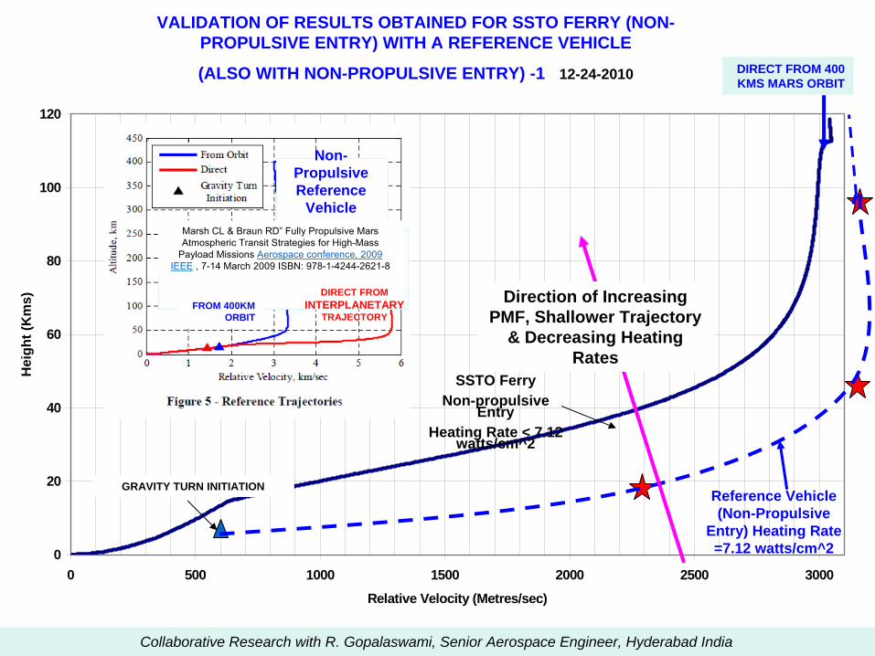
Mars SSTO EDL ProfileHeight as a Function of Relative Velocity
Entry Mass: 69.70 Tonnes; Vehicle Dia.: 14m; Ballistic Coefficient 348.28
0
20
40
60
80
100
120
0 500 1000 1500 2000 2500 3000
Relative Velocity (Metres/sec)
Hei
ght (
Km
s)
Marsh CL & Braun RD”
Fully Propulsive Mars Atmospheric Transit Strategies for High-Mass
Payload Missions Aerospace conference, 2009 IEEE
, 7-14 March 2009 ISBN: 978-1-4244-2621-8
DIRECT FROM 400 KMS MARS ORBIT
GRAVITY TURN INITIATION
FROM 400KM ORBIT
DIRECT FROM INTERPLANETARY
TRAJECTORY
Direction of Increasing PMF, Shallower Trajectory
& Decreasing Heating Rates
Reference Vehicle (Non-Propulsive
Entry) Heating Rate =7.12 watts/cm^2
Non- Propulsive Reference
Vehicle
SSTO Ferry Non-propulsive
Entry Heating Rate < 7.12
watts/cm^2
VALIDATION OF RESULTS OBTAINED FOR SSTO FERRY (NON- PROPULSIVE ENTRY) WITH A REFERENCE VEHICLE
(ALSO WITH NON-PROPULSIVE ENTRY) -1 12-24-2010
Collaborative Research with R. Gopalaswami, Senior Aerospace Engineer, Hyderabad India
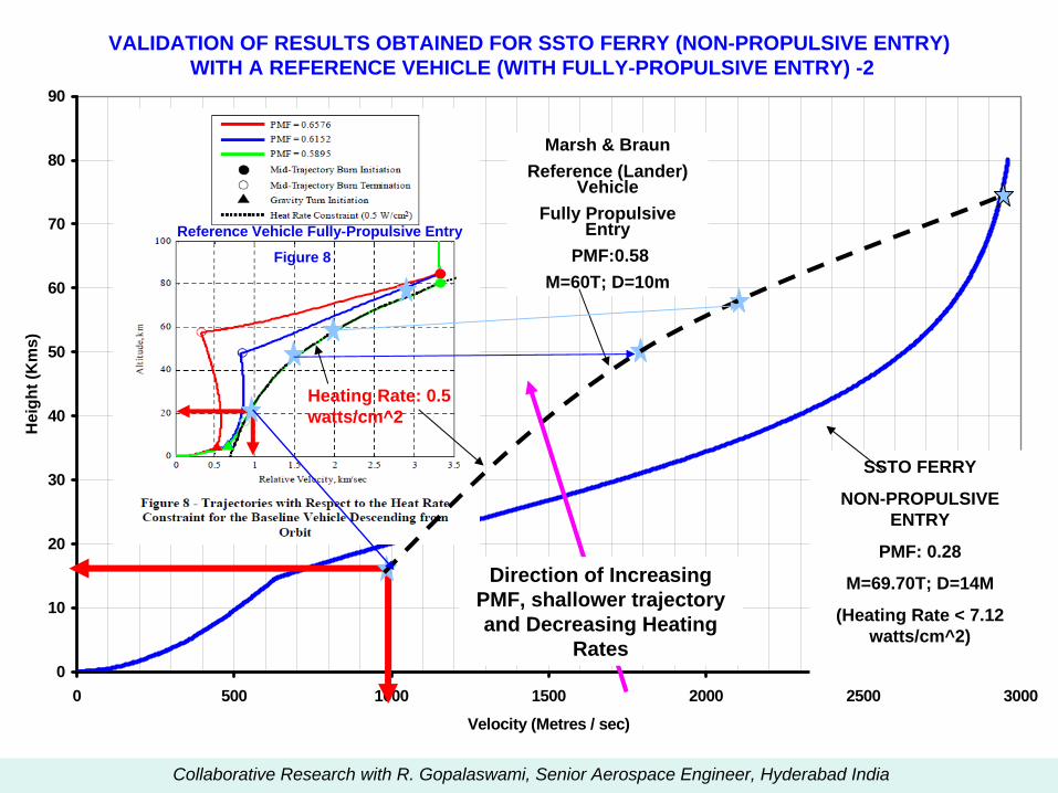
Mars SSTO Ferry Atmospheric Entry & Descent Trajectory
0
10
20
30
40
50
60
70
80
90
0 500 1000 1500 2000 2500 3000
Velocity (Metres / sec)
Hei
ght (
Km
s)
Marsh & BraunReference (Lander)
Vehicle Fully Propulsive
EntryPMF:0.58
M=60T; D=10m
SSTO FERRY
NON-PROPULSIVE ENTRY
PMF: 0.28
M=69.70T; D=14M
(Heating Rate < 7.12 watts/cm^2)
Heating Rate: 0.5 watts/cm^2
Direction of Increasing PMF, shallower trajectory and Decreasing Heating
Rates
VALIDATION OF RESULTS OBTAINED FOR SSTO FERRY (NON-PROPULSIVE ENTRY)WITH A REFERENCE VEHICLE (WITH FULLY-PROPULSIVE ENTRY) -2
Reference Vehicle Fully-Propulsive Entry
Figure 8
Collaborative Research with R. Gopalaswami, Senior Aerospace Engineer, Hyderabad India
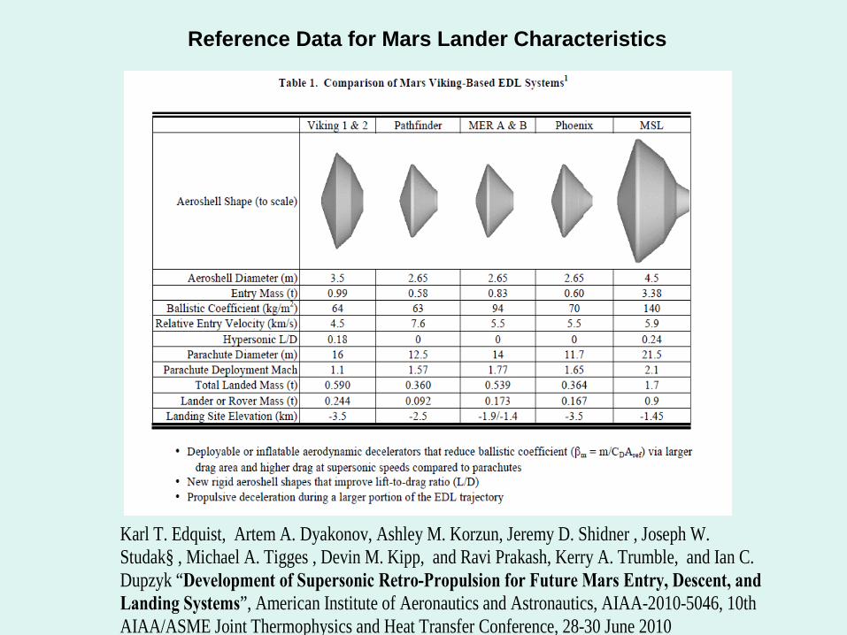
Reference Data for Mars Lander Characteristics
Karl T. Edquist, Artem A. Dyakonov, Ashley M. Korzun, Jeremy D. Shidner , Joseph W. Studak§ , Michael A. Tigges , Devin M. Kipp, and Ravi Prakash, Kerry A. Trumble, and Ian C. Dupzyk “Development of Supersonic Retro-Propulsion for Future Mars Entry, Descent, and Landing Systems”, American Institute of Aeronautics and Astronautics, AIAA-2010-5046, 10th AIAA/ASME Joint Thermophysics and Heat Transfer Conference, 28-30 June 2010
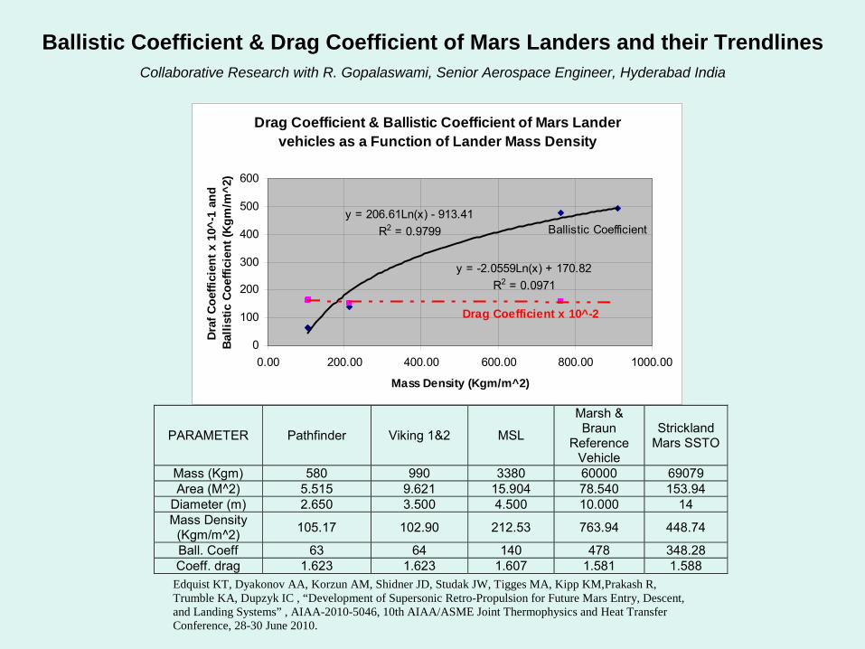
Ballistic Coefficient & Drag Coefficient of Mars Landers and their TrendlinesCollaborative Research with R. Gopalaswami, Senior Aerospace Engineer, Hyderabad India
Drag Coefficient & Ballistic Coefficient of Mars Lander vehicles as a Function of Lander Mass Density
y = 206.61Ln(x) - 913.41R2 = 0.9799
y = -2.0559Ln(x) + 170.82R2 = 0.0971
0
100
200
300
400
500
600
0.00 200.00 400.00 600.00 800.00 1000.00
Mass Density (Kgm/m^2)
Draf
Coe
ffici
ent x
10^
-1 a
nd
Balli
stic
Coe
ffici
ent (
Kgm
/m^2
) Ballistic Coefficient
Drag Coefficient x 10^-2
PARAMETER Pathfinder Viking 1&2 MSL
Marsh & Braun
Reference Vehicle
Strickland Mars SSTO
Mass (Kgm) 580 990 3380 60000 69079 Area (M^2) 5.515 9.621 15.904 78.540 153.94
Diameter (m) 2.650 3.500 4.500 10.000 14 Mass Density
(Kgm/m^2) 105.17 102.90 212.53 763.94 448.74
Ball. Coeff 63 64 140 478 348.28 Coeff. drag 1.623 1.623 1.607 1.581 1.588
Edquist KT, Dyakonov AA, Korzun AM, Shidner JD, Studak JW, Tigges MA, Kipp KM,Prakash R, Trumble KA, Dupzyk IC , “Development of Supersonic Retro-Propulsion for Future Mars Entry, Descent, and Landing Systems” , AIAA-2010-5046, 10th AIAA/ASME Joint Thermophysics and Heat Transfer Conference, 28-30 June 2010.

Selected Links to Information Sources for this Presentation
DEPOTS:
•
The Case for Orbital Propellant Depots: http://www.slideshare.net/jongoff/sa08-prop-depot-
panel-jon-goff
•
Space Gas Station Would Blast Huge Payloads to the Moon: http://www.popularmechanics.com/science/space/news/4224660
•
On-Orbit Propellant Resupply Options for Mars Exploration Architectures: http://www.ssdl.gatech.edu/papers/conferencePapers/IAC-2006-D1.1.01.pdf
MARS EDL:•
High Mass Mars Entry, Descent, and Landing Architecture Assessment: http://www.ssdl.gatech.edu/papers/conferencePapers/AIAA-2009-6684.pdf
•
Development of Supersonic Retro-Propulsion for Future Mars Entry, Descent, and Landing Systems: http://www.ssdl.gatech.edu/papers/conferencePapers/AIAA-2010-5046.pdf
•
Fully-Propulsive Mars Atmospheric Transit Strategies for High-Mass Payload Missions: http://www.ssdl.gatech.edu/papers/conferencePapers/IEEE-2009-1219.pdf
•
A Concept For The Entry, Descent, And Landing Of High-Mass Payloads At Mars: http://www.ssdl.gatech.edu/papers/conferencePapers/IAC-2008-D2.3.9.pdf
•
Mars Exploration Entry, Descent and Landing Challenges: http://www.ssdl.gatech.edu/papers/conferencePapers/IEEE-2006-0076.pdf
•
Sizing of an Entry, Descent, and Landing System for Human Mars Exploration http://www.ssdl.gatech.edu/papers/conferencePapers/AIAA-2006-7427.pdf
•
Atkinson, Nancy: http://www.universetoday.com/2007/07/17/the-mars-landing-approach-
getting-large-payloads-to-the-surface-of-the-red-planet/
•
Design of an Entry System for Cargo Delivery to Mars, Thompson, Robert, et al, http://www.ssdl.gatech.edu/papers/conferencePapers/IPPW-2007-Thompson.pdf