IP &) ' $ $ # IP Network Infrastructure for Video Transmission

HELSINKI UNIVERSITY OF TECHNOLOGYLaboratory of Telecommunications TechnologyS-38.128 Telecommunication Technology, special assignment
Access to IP network from a fixed networkusing Voice over IP
Name: Kaisa Kettunen, [email protected]
Supervisor: Vesa KosonenHelsinki University of Technology
Instructor: Erkki KaraharjuOy LM Ericsson Ab
Returned: 1.11.1999

S-38.128 Telecommunication Technology Special Assignment
1
Access to IP network from a fixed network using Voiceover IP
Kaisa KettunenTKK, Laboratory of Telecommunications Technology
Summary
This assignment was written as a requirement for the course S-38.128Telecommunication Technology Special Assignment, during the summer and fallof 1999. It studies the transition of speech from a fixed network based PCMsamples to a packet switched IP network. The goal was to become familiar withVoice over IP (VoIP) and it’s network elements.
The access to IP network is established by routing the transferred signal, i.e.speech or fax, through a Gateway element, which carries out the conversion fromone information format to another. In practise, the process includes echocancellation, coding, cryption and formatting to the correct form. Also thesignalling messages are converted.
The VoIP telephony system has many advantages and it will surely become moresignificant in the next few years.

S-38.128 Telecommunication Technology Special Assignment
2
TABLE OF CONTENTS
Summary...........................................................................................................................................................1
ABBREVIATIONS ..........................................................................................................................................4
1 INTRODUCTION........................................................................................................................................5
2 WHAT IS VOICE OVER IP ? ....................................................................................................................5
2.1 ADVANTAGES AND DISADVANTAGES OF USING VOIP ...............................................................................6
2.2 THE STRUCTURE OF A VOIP NETWORK.....................................................................................................6
2.2.1 Voice Gateway .................................................................................................................................7
2.2.2 Gatekeeper .......................................................................................................................................7
2.2.3 Accounting Server............................................................................................................................7
2.2.4 Management Site..............................................................................................................................7
2.2.5 AAA Server.......................................................................................................................................8
2.2.6 O&M Operator ................................................................................................................................8
2.2.7 IVR ...................................................................................................................................................8
2.2.8 MCU.................................................................................................................................................8
2.2.9 SS7 Gateway ....................................................................................................................................8
2.2.10 Terminals.......................................................................................................................................8
3 USED FORMES OF INFORMATION......................................................................................................8
3.1 SPEECH IN PCM SAMPLES ........................................................................................................................9
3.2 THE IP PACKET STRUCTURE .....................................................................................................................9
4 CALL CONTROL IN VOIP .....................................................................................................................11
4.1 PSTN – IP – PSTN CALL.......................................................................................................................12
4.2 PC – IP – PSTN CALL ...........................................................................................................................14
4.3 FAX – IP – FAX CALL .............................................................................................................................15
4.4 MS – IP – PSTN CALL...........................................................................................................................15
5 SIGNALLING ............................................................................................................................................16
5.1 COMMON CHANNEL SIGNALLING CCS...................................................................................................16
5.1.1 Signalling with SS7 Gateway .........................................................................................................17
5.1.1.1 Connection establishment to other network components ....................................................................... 17
5.1.1.2 ISUP message conversion....................................................................................................................... 18
5.1.2 Signalling through Voice Gateway ................................................................................................18
5.2 CHANNEL ASSOCIATED SIGNALLING CAS..............................................................................................18
6 CHARGING ...............................................................................................................................................19
7 THE VOICE GATEWAY .........................................................................................................................19
7.1 THE SPEECH PROCESSING MODULE .......................................................................................................20
7.2 THE VOICE GATEWAY IMPLEMENTATION ...............................................................................................22
8 CONCLUSIONS.........................................................................................................................................23
REFERENCES...............................................................................................................................................24

S-38.128 Telecommunication Technology Special Assignment
3
APPENDIX 1. UNVALIDATED PSTN-IP-PSTN CALL SETUP. SIMPLIFIED DIAGRAM...............25
APPENDIX 2. UNVALIDATED PSTN-IP-PSTN CALL CLEARING. SIMPLIFIED DIAGRAM. .....26
S-38.128 Telecommunication Technology Special Assignment
4
ABBREVIATIONS
AB Access BrokerAGW A-bis GatewayAN Access NodeAPI Application Program InterfaceBTS BasestationCAS Channel Associated SignallingCCS Common Channel SignallingCDR Call Detail RecordCIC Circuit Identification CodeCPT Call Progress TonesDPC Destination Point CodeDTMF Dual Tone Multiple FrequencyETC Exchange Terminal CircuitFPAD Facsimile Packet Assembly DeviceGSIP GSM over IPGW GatewayIP Internet ProtocolIPT IP TelephonyISDN Integrated Services Digital NetworkISUP ISDN User PartITU International Telecommunication UnionIVR Interactive Voice ResponseLAN Local Area NetworkMCU Multipoint Conference UnitMFC Multi Frequency CompelledMTP Message Transfer PartNI Network IndicatorOPC Originating Point CodeOSI Open Systems InterconnectionPCM Pulse Code ModulationPIN Personal Identification NumberPSTN Public Switched Telephony NetworkQoS Quality of ServiceRTP Real Time ProtocolSN Service NodeSPC Signalling Point CodeSS7 Signalling System number 7TCP Transmission Control ProtocolTDM Time Division Multiplexingt-ISUP Thin ISUPUDP User Datagram ProtocolVG Voice GatewayVoIP Voice over IP
S-38.128 Telecommunication Technology Special Assignment
5
1 INTRODUCTION
The society is changing. During the last decade, companies involved in communication andinformation technology have gotten a strong foothold. The number of Internet connections andmobile phones has been increasing and changing the person to person communication. Todaywe stand on the verge of information society, where data transfer among companies andpeople will continue to increase and versatile.
But the growth and new requirements of the data put pressure on research anddevelopment. Suppliers and operators face the challenge of enabling the transfer of new formsof information, for example video image, as effectively and extensively as possible, butmaintaining the compatibility and the practicability of existing hardware. In addition to this,the usage must be made simple and reasonable in price for the average user. As fortelecommunication, more and more services will be moved to the already existing, world widenetworks using Internet Protocol IP.
Perhaps the most prominent proposition mainly for voice is the Voice over IP, betterknown as VoIP. Because of it’s flexibility and simplicity, it has quickly become the next mostlikely cash magnet. VoIP can be seen as the first product of the next generation ofdatacommunication solutions. It’s success will to some extend anticipate the rise, or fall, ofother products to come.
In order to establish a call from a traditional telephone network via the Internet, somemodifications have to be made. This special assignment will study the conversion of thespeech signal from PCM samples of a fixed network to the packet data used by the IPnetworks. The goal is to become familiar with VoIP network and it's elements, especially theVoice Gateway.
This document will start with an overview of the VoIP, describing the general concepts,network elements and their role in call establishment. It will then focus on the problem abovegiving an example of a solution and introducing the function and structure of the VoiceGateway.
2 WHAT IS VOICE OVER IP ?
Up till now, information has been carried over the circuit switched connections of fixednetworks, such as the public switched telephone network PSTN. Since the introduction of thepacket networks, this exchange of voice, fax, and other forms of information has graduallymoved towards the IP networks. The technologies enabling this transformation are generallyreferred to as IP telephony.
In the mixture of relatively unregulated IP telephony, Voice over IP is an attempt at acommon standard. As the name indicates, it is a telephony system, which describes thefacilities managing the delivery of voice information using the internet protocol. The conceptis based on i.e. the ITU-T H.323 standard defining multimedia transmissions over packetnetworks.
S-38.128 Telecommunication Technology Special Assignment
6
LE
VoiceGateway
send
receive
LE
VoiceGatewayreceive
send
PSTN
LE = Local exchange
A B
IP
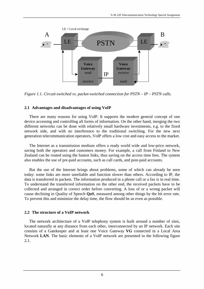
Figure 1.1. Circuit-switched vs. packet-switched connection for PSTN – IP – PSTN calls.
2.1 Advantages and disadvantages of using VoIP
There are many reasons for using VoIP. It supports the modern general concept of onedevice accessing and controlling all forms of information. On the other hand, merging the twodifferent networks can be done with relatively small hardware investments, e.g. to the fixednetwork side, and with no interference to the traditional switching. For the new nextgeneration telecommunication operators, VoIP offers a low cost and easy access to the market.
The Internet as a transmission medium offers a ready world wide and low-price network,saving both the operators and customers money. For example, a call from Finland to NewZealand can be routed using the fastest links, thus saving on the access time fees. The systemalso enables the use of pre-paid accounts, such as call cards, and post-paid accounts.
But the use of the Internet brings about problems, some of which can already be seentoday: some links are more unreliable and function slower than others. According to IP, thedata is transferred in packets. The information produced in a phone call or a fax is in real time.To understand the transferred information on the other end, the received packets have to becollected and arranged in correct order before converting. A loss of or a wrong packet willcause declining in Quality of Speech QoS, measured among other things by the bit error rate.To prevent this and minimize the delay time, the flow should be as even as possible.
2.2 The structure of a VoIP network
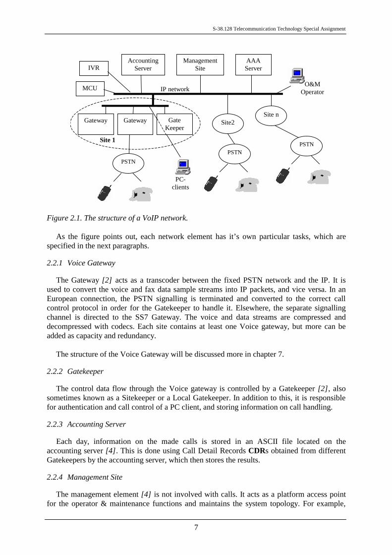
The network architecture of a VoIP telephony system is built around a number of sites,located naturally at any distance from each other, interconnected by an IP network. Each siteconsists of a Gatekeeper and at least one Voice Gateway VG connected in a Local AreaNetwork LAN. The basic elements of a VoIP network are presented in the following figure2.1.
S-38.128 Telecommunication Technology Special Assignment
7
GateKeeper
AccountingServer
ManagementSite
AAAServer
Gateway Gateway
IP network
Site 1
Site2Site n
O&MOperator
PC-clients
PSTN
PSTNPSTN
IVR
MCU
Figure 2.1. The structure of a VoIP network.
As the figure points out, each network element has it’s own particular tasks, which arespecified in the next paragraphs.
2.2.1 Voice Gateway
The Gateway [2] acts as a transcoder between the fixed PSTN network and the IP. It isused to convert the voice and fax data sample streams into IP packets, and vice versa. In anEuropean connection, the PSTN signalling is terminated and converted to the correct callcontrol protocol in order for the Gatekeeper to handle it. Elsewhere, the separate signallingchannel is directed to the SS7 Gateway. The voice and data streams are compressed anddecompressed with codecs. Each site contains at least one Voice gateway, but more can beadded as capacity and redundancy.
The structure of the Voice Gateway will be discussed more in chapter 7.
2.2.2 Gatekeeper
The control data flow through the Voice gateway is controlled by a Gatekeeper [2], alsosometimes known as a Sitekeeper or a Local Gatekeeper. In addition to this, it is responsiblefor authentication and call control of a PC client, and storing information on call handling.
2.2.3 Accounting Server
Each day, information on the made calls is stored in an ASCII file located on theaccounting server [4]. This is done using Call Detail Records CDRs obtained from differentGatekeepers by the accounting server, which then stores the results.
2.2.4 Management Site
The management element [4] is not involved with calls. It acts as a platform access pointfor the operator & maintenance functions and maintains the system topology. For example,
S-38.128 Telecommunication Technology Special Assignment
8
alarm information and routing configurations are stored to the site.
2.2.5 AAA Server
AAA server [4] gets it’s name from the three procedures it is involved with:Authentication, Accounting and Authorisation when the traffic is unvalidated. The server alsocontains the subscriber database.
2.2.6 O&M Operator
The fact that the platform and other elements are connected to an IP network facilitates theOperation & Maintenance [4]. The procedures can be done remotely, since all componentscan be accessed through i.e. a graphical interface using a web browser.
2.2.7 IVR
Interactive voice response IVR [2] is an optional network element, which is used inauthorising a call and in authentication. It can send voice messages to a subscriber and receiveDTMF tones, which in turn are then translated to corresponding digit information.
2.2.8 MCU
For conferencing purposes, the LAN network needs a Multipoint Control Unit MCU [2].This element connects three or more terminals and gateways into a multipoint conference. Itcan also be used to make a point-to-point connection between two terminals, possibly laterestablishing a multipoint conference.
2.2.9 SS7 Gateway
As the signalling information from a fixed network switch can also be received through aseparate network, it must be converted to the IP network in the SS7 Gateway [5]. The ISUPsignalling messages, for example, are converted between SS7 and TCP/IP message formats.
The conversion of the signalling channel and the function of the SS7 Gateway is discussedmore with signalling protocols.
2.2.10 Terminals
The VoIP supports calls made to/from PSTN, PC or a fax. In the future, also mobile, i.e.GSM, calls will be supported.
3 USED FORMES OF INFORMATION
The difference in information forms causes problems in the transfer and speech processingof the signal. For IP packets, the processing methods are totally different from the ones usedwith PCM samples. In spite of this, the conversion should be done as efficiently as possible,maintaining the original quality of speech and correct timing at the same time.
The two forms of information are discussed next.

S-38.128 Telecommunication Technology Special Assignment
9
3.1 Speech in PCM samples
The speech signal produced by a caller is in analog form. When a fixed network’ssubscriber makes a call, the data processing is started at the switch, where the speech signal isdigitally coded using pulse code modulation PCM.
The analog signal on the bandwith of 300 - 3400 Hz is first sampled by measuring theamplitude in intervals according to the sample frequency, normally 8000 Hz. The samples arethen quantizised (rounded to defined layers of values) and presented as a string of binaryvalues. The result is a digital voice channel of 64 kbit/s [8].
Before transmitting, a number of channels are multiplexed according to time divisionmultiplexing TDM to compose a frame. The multiplexer combines the data from each channelinto a time frame, which is then sent out. This process is repeated continuously.
On the other end, the PCM frames are received and unpacked by performing thecorresponding operations “backwards”.
32 slots x 8 bits x 8000 Hz = 2048 kbit/s
European PCM frame E1
(24 slots x 8 bits + 1 bit) x 8000 Hz = 1544 kbit/s
American PCM frame T1
125 ms
Figure 3.1. The PCM frame [8].
As illustrated in the previous figure, there are differences in the PCM frames between thetwo continents. In Europe, the quantization is done according to the A-law, where as in NorthAmerica and Japan the corresponding principle is µ-law. Also the number of used channels isdifferent. The European PCM frame E1 consists of 30 channels, one frame alignment wordand one signalling frame multiplexed into a flow of 2048 kbit/s [8]. The version used inNorth America and Japan, named T1, includes 24 voice channels and one frame alignmentmultiplexed into 1544 kbit/s. Because of the differences, the data transferred between the twocontinents needs to be converted to correct form on the American side.
3.2 The IP packet structure
The information in the Internet is packed using a combination of several protocol layersfounded on the OSI model. The lowest layer functions as a network interface handling thephysical interface with the cable, in this case the Ethernet.

S-38.128 Telecommunication Technology Special Assignment
10
Ethernet
IP
UDP TCP
RTP
Link layer
Network layer
Transport layer
Application layer Application PPP
Figure 3.2. The RTP/UDP/IP protocol suite in OSI layers.
The general concept is that the data packets are formed by appending the used protocolheaders in the processing order to the transferred data. Each layer considers the data from thenext higher level as a payload and adds it’s own header before it.
EthernetHeader14 bytes
IPHeader20 bytes
UDPHeader8 bytes
RTPHeader12 bytes
A number of encoded(and encrypted) speech
frames
Figure 3.3. The IP packet structure in VoIP.
The protocol suite is based on the IP protocol [7], which defines the transfer of informationin packets between computers. The header includes a 32-bit IP address of the sender, as wellas the destination address handled by the gateways. Since the IP packets are sent separately,they can travel through different routes in the network and therefore also arrive at differenttimes.
32-bit source IP address
32-bit destination IP address
Options (if any)
Data
8-bit time to live(TTL)
16-bit header checksum8-bit protocol
16-bit identification 13-bit fragment offset3-bitflags
16-bit total length (in bytes)8-bit type of service(TOS)
4-bit headerlength
4-bitversion
20bytes
Figure 3.4. Structure of the IP header [7].
On top of the IP, another protocol is used to actually get the data from a computer toanother. The most common option is the Transmission Control Protocol TCP, but in case ofraw data, such as in VoIP, User Datagram Protocol UDP is used. The TCP verifies the correctend-to-end delivery, whereas with the UDP there are no quarantees of the packet everreaching the receiver. The UDP header is also shorter, which increases the bit efficiency.
S-38.128 Telecommunication Technology Special Assignment
11
Another difference between these two is that unlike TCP, UDP has no sequencing. It doesn’tdivide the data to packets nor assemble them at the receiving end. All this is left to theapplication. On the other hand, this feature can be used to save process time, when using smallpackages.
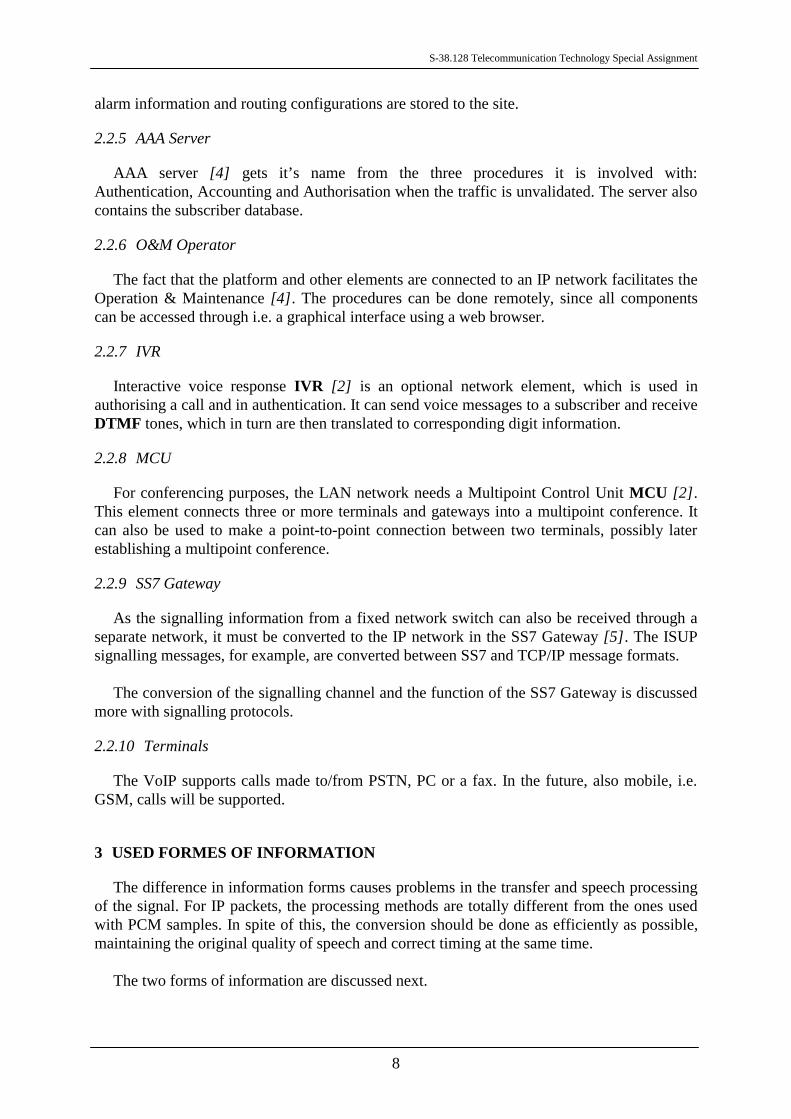
UDP provides a 16-bit port number, which enables it to distinguish between users evenfrom the same client. Since the IP header does not care if the data was transmitted intact, thetransmission is first checked in the UDP header with a 16-bit checksum.
Data (if any)
16-bit UDP checksum16-bit UDP length
8bytes
16-bit destination port number16-bit source port number
Figure 3.5. Structure of the UDP header [7].
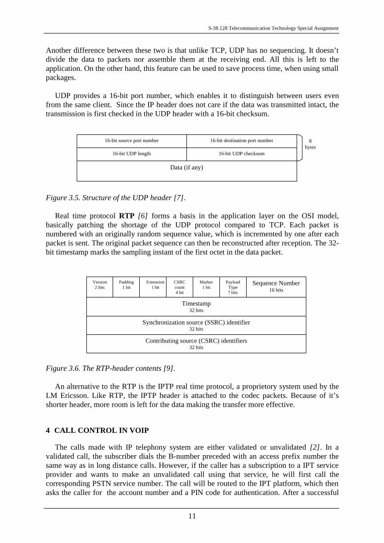
Real time protocol RTP [6] forms a basis in the application layer on the OSI model,basically patching the shortage of the UDP protocol compared to TCP. Each packet isnumbered with an originally random sequence value, which is incremented by one after eachpacket is sent. The original packet sequence can then be reconstructed after reception. The 32-bit timestamp marks the sampling instant of the first octet in the data packet.
Version2 bits
Padding1 bit
Timestamp32 bits
Synchronization source (SSRC) identifier32 bits
Contributing source (CSRC) identifiers32 bits
Extension1 bit
CSRCcount4 bit
Marker1 bit
PayloadType7 bits
Sequence Number16 bits
Figure 3.6. The RTP-header contents [9].
An alternative to the RTP is the IPTP real time protocol, a proprietory system used by theLM Ericsson. Like RTP, the IPTP header is attached to the codec packets. Because of it’sshorter header, more room is left for the data making the transfer more effective.
4 CALL CONTROL IN VOIP
The calls made with IP telephony system are either validated or unvalidated [2]. In avalidated call, the subscriber dials the B-number preceded with an access prefix number thesame way as in long distance calls. However, if the caller has a subscription to a IPT serviceprovider and wants to make an unvalidated call using that service, he will first call thecorresponding PSTN service number. The call will be routed to the IPT platform, which thenasks the caller for the account number and a PIN code for authentication. After a successful

S-38.128 Telecommunication Technology Special Assignment
12
identification, the subscriber is asked to dial the B-number.
The subscriber can make several ”follow on” calls once the unvalidated connection hasbeen established, thus saving time. Instead of hanging up, the caller dials a special DTMFsequence, which clears the connection to the present subscriber. A new B-number can now bedialed. The possibility to use ”follow on” service is independent from the subscriber's role incall termination.
Basically, the VoIP call is a combination of different technologies and co-operation ofnetwork components in charge of specific aspects of the call establishment. For example, thetwo Gatekeepers talk directly to each other with TCP messages, but the messaging betweenthe Voice Gateways is done using UDP format. The complexity can also be seen focusing one.g. connection setup. The system allows phone–phone, PC–phone and fax calls, all of whichare handled next.
4.1 PSTN – IP – PSTN call
In case of a PSTN-IP-PSTN call [2], the setup is largely effected by the fact whether thesubscriber is validated or unvalidated. Since an unvalidated call setup covers the situationsoccurring also in a validated call, we will use it as an example. Hence the subscriber has anaccount and a PIN code from a service provider, who in turn maintains a subscriber serviceprofile on the caller including i.e. the type of service (pre-paid or post-paid).
As the service provider number is dialed, a connection to the PSTN switch is made. Theswitch completes the call in a normal manner to the answering Voice Gateway. The VG thenpasses the setup to the Gatekeeper, which starts the authentication procedure by setting up aconnection to the IVR to request the authentication from the caller [4]. The information codesgiven by the subscriber are directed to the AAA Server for examination. For a positiveidentification, the server returns the Quality of Service class specified in the subscriberprofile. At this point also other information, e.g. the remaining amount of cash in case of pre-paid call, may be delivered. Finally, the IVR is disconnected.

S-38.128 Telecommunication Technology Special Assignment
13
OriginatingVoice Gateway
OriginatingSitekeeper
InteractiveVoice Response
TerminatingSitekeeper
DTMF tones
Setup
Setup
Facility
Call proceeding
Connect
Open logical channel
Setup
Connect
Open logical channel
OLC Acknowledge OLC Acknowledge
User Input Indications User Input Indications
Release completeClose logical channel
CLC Acknowledge
Call proceeding
Figure 4.1. The setup diagram for an unvalidated connection. Simplified diagram [4].
Since the subscriber now has an unvalidated connection to the IPT platform, the B-numberis requested and forwarded on to the Gatekeeper. With help of the subcriber profile, e.g.dynamic routing or requested QoS, the number is analyzed and routed to the correctterminating Gatekeeper. Also the originating digits are modified.
At the terminating Gatekeeper another analysis is made and the call is routed to theterminating Voice Gateway. A call to the B-subscriber is setup and completed by the PSTNswitch. The call is established, when the B-subscriber goes on-hook.
The call setup diagram is presented in the Appendix 1.
The termination process is done in the normal way. The charging information (CDR) fromboth VGs is sent to the corresponding Accounting Servers, and also to the AAA Server fromthe originating VG.
The call clearing diagram is presented in the Appendix 2.
For a validated call, the setup procedure does not include the IVR nor the subscriberidentification process presented previously. The originating Gatekeeper just determinates theroute and interconnects the both Voice Gateways. Information related to a certain call ishandled with an unique call identification number in the Gatekeeper.
The following figure illustrates the traffic paths through network elements during a voicecall. It can be seen that the call signalling path and the voice path are different. This is donefor example to save network resources and capasity.

S-38.128 Telecommunication Technology Special Assignment
14
Gateway
PSTN
GateKeeper
GateKeeper
PSTN
Gateway
IPNetwork
Originatinguser
Terminatinguser
PCclient
PCclient
Call signaling pathVoice path
Figure 4.2. PSTN to PSTN call path [4].
4.2 PC – IP – PSTN call
One of the new features provided by VoIP is the ability to establish and receive calls,including fax, with an ordinary PC. The connection uses a single line serving both as anaccess to the Internet as well as a path for telephone data.
The connection to the PSTN side is established very much the same way as in a PSTN-IP-PSTN call. The PC makes a connection to the assigned Gatekeeper, which finds out the IPaddress of the receiving gateway returning it to the PC. Because all signal processingfunctions are done by the computer, no gateway at the originating end is needed, and a straightconnection from the PC to the terminating gateway can be established. From here on the callis routed normally to the receiver.
While receiving a call from the fixed network, the system works in reversed order. The callis routed from the voice gateway to the receiving gatekeeper. It finds out the access route andonline status of the PC connection for a direct connection. At the PC, the call is routed to aspecific socket handling all the telephone traffic.
Conversion from a telephone number to an IP address in the Voice Gateway uses adynamic connection between the IP address and the temporary identification established bythe caller at log on. In case of an unvalidated call, an Access Broker AB takes the role of anIVR. The system needs no special hardware in order to work.
As an alternative implementation, an application called the Phone Doubler [9] uses anormal telephone Internet connection to establish calls. This application turns the PC’smicrophone and loudspeakers to be equivalent to the telephone’s handset. When the user has aconnection to the Internet through an access server, another virtual telephone line is createdfor the call. Several simultaneous calls can easily be handled. The subscriber doesn’t also have
S-38.128 Telecommunication Technology Special Assignment
15
to close the connection to the service provider between unvalidated calls.
4.3 Fax – IP – Fax call
The IP telephony system supports fax calls [6] treating them almost the same way as thevoice calls. For exmaple, the call setup is handled as in a PSTN-PSTN call. The calling faxsends a CNG tone, normally 1100 Hz for 0,5 s, which is then answered with a CED tone(2100 Hz) by the recepient.
After setup, the second phase is the handshake between the two parts. As a fax-specificproblem, the master party must have a reply in 3 seconds. Hence, a delayed IP packet cancause the sent and received messages to be unequal, which will lead to the call being hung up.Another problem is that the receiving fax needs a continuous fax data stream during the datatransmission.
Solution to these problems is the Facsimile Packet Assembly Device FPAD [9], based onthe protocol used in the inter-gateway fax transmission described in the ITU-T specificationT.38. The purpose of this machine is to handle timeouts during binary commands andresponses, and avoid duplication of messages.
When the Voice Gateway detects a fax call, a fax demodulator is placed on the path. Itconverts the tone information into a suitable format picture data, which is then transmittedthrough the IP network. At the other end, a conversion back to tones is executed by a faxmodulator.
4.4 MS – IP – PSTN call
An IP-based GSM network is sometimes referred to as GSM over IP GSIP [9]. A GSIPcall is based on a normal MS call.
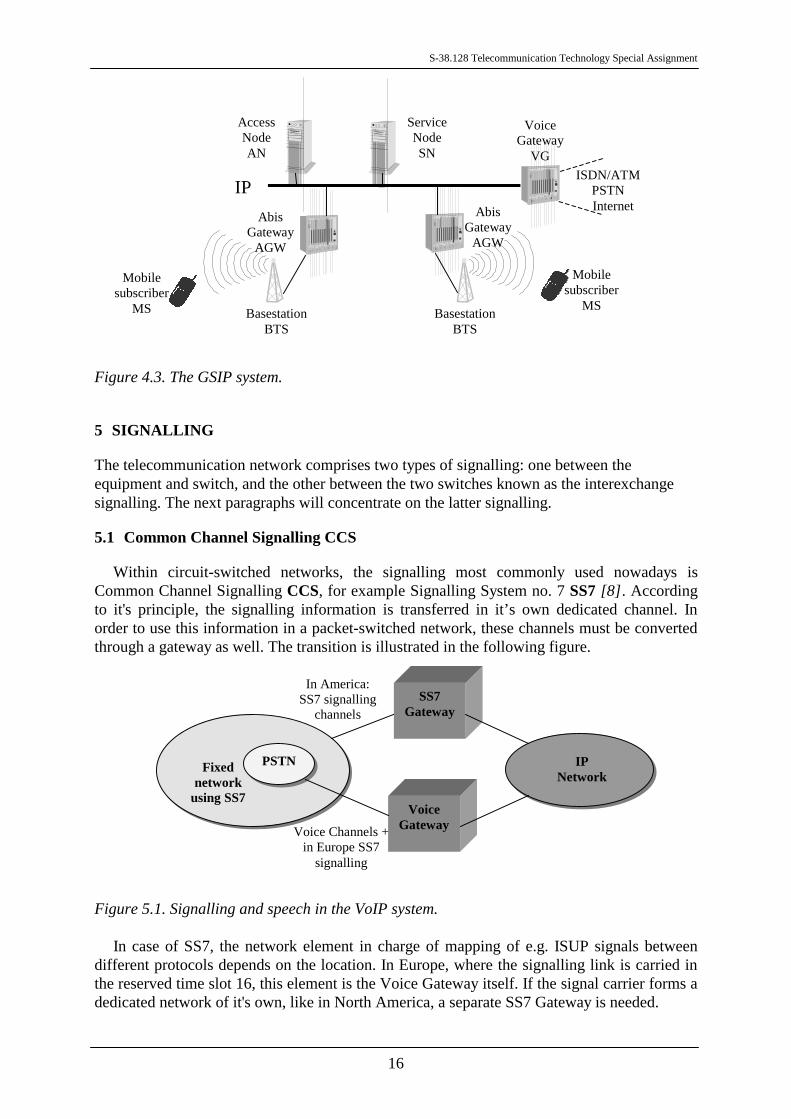
In a MS-IP-MS call, the GSM data from the basestation BTS is first routed to the Accessnode AN consisting of MSC and BSC, and the modified suitable for e.g. LAN network in theAbis Gateway AGW . The system related services, i.e. call setup, user administration andsecurity, are handled by the Service Node SN.
S-38.128 Telecommunication Technology Special Assignment
16
Figure 4.3. The GSIP system.
5 SIGNALLING
The telecommunication network comprises two types of signalling: one between theequipment and switch, and the other between the two switches known as the interexchangesignalling. The next paragraphs will concentrate on the latter signalling.
5.1 Common Channel Signalling CCS
Within circuit-switched networks, the signalling most commonly used nowadays isCommon Channel Signalling CCS, for example Signalling System no. 7 SS7 [8]. Accordingto it's principle, the signalling information is transferred in it’s own dedicated channel. Inorder to use this information in a packet-switched network, these channels must be convertedthrough a gateway as well. The transition is illustrated in the following figure.
Fixednetwork
using SS7
SS7Gateway
VoiceGateway
IPNetwork
PSTN
Voice Channels +in Europe SS7
signalling
In America:SS7 signalling
channels
Figure 5.1. Signalling and speech in the VoIP system.
In case of SS7, the network element in charge of mapping of e.g. ISUP signals betweendifferent protocols depends on the location. In Europe, where the signalling link is carried inthe reserved time slot 16, this element is the Voice Gateway itself. If the signal carrier forms adedicated network of it's own, like in North America, a separate SS7 Gateway is needed.
AbisGateway
AGW
AbisGateway
AGW
BasestationBTS
BasestationBTS
Mobilesubscriber
MS
Mobilesubscriber
MS
VoiceGateway
VG
ServiceNodeSN
AccessNodeAN
IPISDN/ATM
PSTN Internet
S-38.128 Telecommunication Technology Special Assignment
17
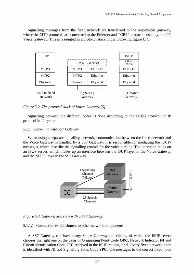
Signalling messages from the fixed network are transferred to the responsible gateway,where the MTP protocols are converted to the Ethernet and TCP/IP protocols used by the IPTVoice Gateway. This is presented as a protocol stack in the following figure [5].
Figure 5.2. The protocol stack of Voice Gateway [5].
Signalling between the different nodes is done according to the H.323 protocol or IPprotocol in IP system.
5.1.1 Signalling with SS7 Gateway
When using a separate signalling network, communication between the fixed network andthe Voice Gateway is handled by a SS7 Gateway. It is responsible for mediating the ISUP-messages, which describe the signalling control for the voice circuits. The operation relies onan ISUP-server, which makes up an interface between the ISUP layer in the Voice Gatewayand the MTP3 layer in the SS7 Gateway.
Figure 5.3. Network overview with a SS7 Gateway.
5.1.1.1 Connection establishment to other network components
A SS7 Gateway can have many Voice Gateways as clients, of which the ISUP-serverchooses the right one on the basis of Originating Point Code OPC, Network Indicator NI andCircuit Identification Code CIC received in the ISUP routing label. Every fixed network nodeis identified with NI and Signalling Point Code SPC. The messages to the correct fixed node
ISUP ISUP
MTP3
MTP2
Physical
MTP3
MTP2
Physical
TCP / IP
Ethernet
Physical
TCP / IP
Ethernet
Physical
SS7 in fixednetwork
SignallingGateway
IPT VoiceGateway
t-ISUP (server) t-ISUP(client)
VoiceGateway
SS7Gateway
TCP/IP
23 SpeechChannels
1 SignallingChannel(56kbps)
S-38.128 Telecommunication Technology Special Assignment
18
are routed on the basis of Destination Point Code DPC [5].
The signals from the fixed network and the VG are transferred transparently. Theconnection to SS7 network is established with an Application Program Interface API onMTP3 layer. The gateway’s ISUP-server acts as MTP3 user receiving events as MTPprimitives. It analyses the messages and converts them to thin-ISUP MTP primitives, whichcan then be sent to the VG. In case a t-ISUP MTP primitive is sent to the SS7 network, theconversion is done in reversed order.
To the VG’s side, the SS7 GW acts as a server listening to it’s client’s (VG) requests. Incase it receives a connection establishment request, the received originating IP address iscompared to the configuration database’s IP address, thus validating the connection. TCP/IPmessages can now be exchanged between the two.
5.1.1.2 ISUP message conversion
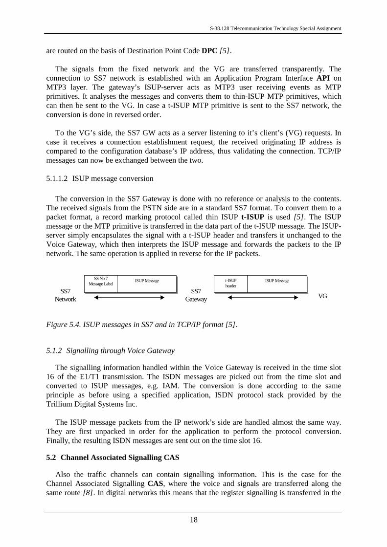
The conversion in the SS7 Gateway is done with no reference or analysis to the contents.The received signals from the PSTN side are in a standard SS7 format. To convert them to apacket format, a record marking protocol called thin ISUP t-ISUP is used [5]. The ISUPmessage or the MTP primitive is transferred in the data part of the t-ISUP message. The ISUP-server simply encapsulates the signal with a t-ISUP header and transfers it unchanged to theVoice Gateway, which then interprets the ISUP message and forwards the packets to the IPnetwork. The same operation is applied in reverse for the IP packets.
Figure 5.4. ISUP messages in SS7 and in TCP/IP format [5].
5.1.2 Signalling through Voice Gateway
The signalling information handled within the Voice Gateway is received in the time slot16 of the E1/T1 transmission. The ISDN messages are picked out from the time slot andconverted to ISUP messages, e.g. IAM. The conversion is done according to the sameprinciple as before using a specified application, ISDN protocol stack provided by theTrillium Digital Systems Inc.
The ISUP message packets from the IP network’s side are handled almost the same way.They are first unpacked in order for the application to perform the protocol conversion.Finally, the resulting ISDN messages are sent out on the time slot 16.
5.2 Channel Associated Signalling CAS
Also the traffic channels can contain signalling information. This is the case for theChannel Associated Signalling CAS, where the voice and signals are transferred along thesame route [8]. In digital networks this means that the register signalling is transferred in the
SS No 7Message Label
ISUP Message t-ISUPheader
ISUP Message
SS7Network VG
SS7Gateway
S-38.128 Telecommunication Technology Special Assignment
19
voice time slots of the corresponding channel and line signalling in separate signalling slot, 16in Europe.
One of the most common CAS signalling is the Multi Frequency Compelled R2 MFC, stillused in many parts of the world. It uses two frequencies from the six different possible ones todeliver a certain information. The requests and responses are further separated by differentfrequencies. We will use it as an example to discuss the CAS signalling path.
The line signalling messages, such as the connection status chances, composed of bit seriesare constantly being transferred in the time slot 16. The gateway listens to the stream findingseparate messages on the basis of their duration. It then filters the signal to a format where thecontents are recognized. If the message is a setup signal, the gateway reserves a channel forthe voice connection and opens it for signalling tones.
The register signalling messages from the trunk consisting of i.e. A- and B-number aretransmitted on the voice channel. The tone messages are detected in the Voice Gateway with aR2 tone detector, from which they are further processed with a special codec [9]. When allthe expected messages have been received, a speech codec for the channel is loaded and thedetector stopped.
The ISUP messages transferred via board processor to the receiving gateway areregenerated into a correct signalling format and sent on to the receiving network.
6 CHARGING
With 3rd generation telecommunication systems, the key word seems to be decentralizing -at least as far as charging is concerned. The charging element previously closely tied to thetraditional network along with other components is now becoming more and more a thirdparty application on the Internet. On the other hand, the integration to the network must besimple.
So far the billing information has been collected in batches. With systems such as VoIP,where the emphasis is on real-time, this is no longer convenient. New features, such as up todate information on an IPT account balance, must be supported. The possibilities are endless.Using billing data collected from e.g. AAA-Servers, the application is able to perform real-time rating and adapt to the current situation by varying bandwidth on usage ad hoc, makingservices and pricing plans. The customers can receive alerts from the billing center or berewarded with discounts based on usage. Combiding charging with Internet bankingapplications allows easy refilling of a calling card [1].
Naturally, the billing center will still maintain statistical information on the calls made. Inaddition, it will support the pre-paid calling card and zone-based rating.
7 THE VOICE GATEWAY
In theory, the Voice Gateway can be thought to consist of the following componentsdescribed below.
S-38.128 Telecommunication Technology Special Assignment
20
ETC
Control
SpeechProcessing
Module
IPi/f
VG
payload
Ctrl
IPPCM
PSTN
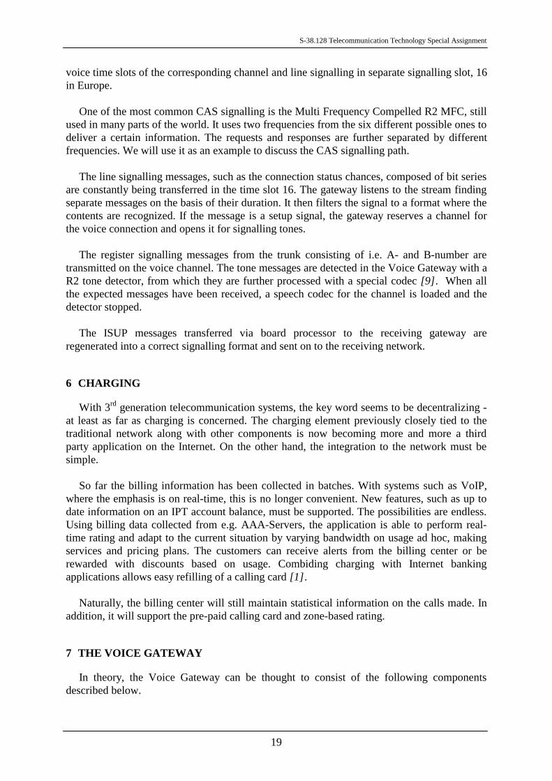
Figure 7.1. A schematic picture of the Voice Gateway [9].
The interface to the PSTN side is known as Exchange Terminal Circuit ETC [9]. Itteminates either a 2048 kbit/s E1 or a 1644 kbps T1 link, on which the information istransferred in PCM.
The data packets are transmitted to the packet switched network, e.g. Local Area NetworkLAN, using the IP interface. The most commonly used LAN technology is the Ethernet, i.e.the widely used 10BASE-T with a transmission speed of 10 Mbit/s. For more demandingbackbone systems, a 100BASE-T supporting 100 Mbit/s is used.
The control unit manages the speech processing module according to the signal mediatedfrom the interfaces. For example, it decides which processing devices are to be used at acertain time.
7.1 The Speech Processing Module
From the signal’s point of view, the Voice Gateway can be seen as a group of detectors orgenerators controlling the conversion process for different types of data. The signal processing[9] can be further illustrated with the following flow-chart.

S-38.128 Telecommunication Technology Special Assignment
21
EchoCanceller
R2tone
generator
Faxmodulator
Faxdemond
IPPSTN
(later phase)
(later phase)
CPTgenerator
DTMFgenerator
Errorconcealm
Speechdecoder
Speechcoder
DTMFdetector
Fax&modemdetector
R2tone
detector
Decryption
Encryption
Jitterbuffer
Packbuffer
Figure 7.2. Signal processing inside the Voice Gateway [9].
One of the main advantages of using VoIP are it’s low-cost long distance calls. But longtransfers through IP cause delay heard as disturbing echo on the PSTN side in a PSTN/PC-IP-PSTN connection. This is prevented with an echo canceller on the PSTN side of the VoiceGateway.
In spite of all possibilities, it is fairly safe to say that speech will remain the most commoninformation transmitted with VoIP. The speech signal is first compressed before sending it tothe IP. This is done with a speech coder to save bandwith, resulting to a bit stream with atransmission rate lower than the original 64 kbit/s. Since the transfer in the IP network isrelatively transparent, the signal is then encrypted to make interception more difficult. Thepurpose of the pack buffer is to assemble the data packets by filling them with a correctamount of coded speech frames and adding the RTP header.
When receiving speech from the IP network, the signal is naturally correspondinglydecrypted and decoded. To ensure a continuous bit stream required by the decoder, a jitterbuffer is used to temporarily store a number of packets.
In addition to speech, the PCM signal can also contain controlling information transmitted
S-38.128 Telecommunication Technology Special Assignment
22
in tones. To interpret them correctly after a packet transfer, they must be extracted from theoriginal signal before coding and processed separately in dedicated applications to prevent thepossible distortion and hence misinterpretation caused by some codecs.
One of this type of tone information is the Dual Tone Multi Frequency DTMF, which incase of VoIP detected and generated separately. The DTMF can be used to choose optionsduring a call. Each number from the phone’s numeric pad translates into two tones of specifichigh and low frequencies, which are then interpreted in the switch to the correspondingcontrol data.
In case of Channel assosiated signalling CAS, i.e. R1 or R2, the speech channel containsalso signalling information, which has to be separated and then generated in order to establisha call. If the connection is made from a mobile subscriber or a PC to a PSTN subscriber, thecall progress tones CPT, i.e. the busy tone, must also be generated.
The fax and data calls are detected based on the CNG or CED tones of the transfer. If amodulator or demodulator is used to separate the fax or data calls, the type of data must beknown to the detector.
Transmitting speech as a packet data requires that all the packets arrive to destinationwithout significant delay. The error situations of a packet missing or being late are handled bythe error concealment. One, codec-independent solution is that the last decoded packet isrepeated, attenuated and distorted. Another way is to manipulate the previously encoded bitstream to get a noisier and attenuated stream and send it to the speech coder.
7.2 The Voice Gateway implementation
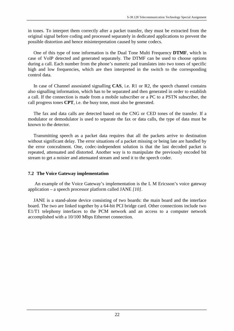
An example of the Voice Gateway’s implementation is the L M Ericsson’s voice gatewayapplication – a speech processor platform called JANE [10].
JANE is a stand-alone device consisting of two boards: the main board and the interfaceboard. The two are linked together by a 64-bit PCI bridge card. Other connections include twoE1/T1 telephony interfaces to the PCM network and an access to a computer networkaccomplished with a 10/100 Mbps Ethernet connection.
S-38.128 Telecommunication Technology Special Assignment
23
Figure 7.3. The main board of the L M Ericsson’s JANE.
One JANE is capable of handling up to 30 channels, but with paralleling more boardsmultiple channels can be achieved.
8 CONCLUSIONS
From the previous chapters it is easy to see that the IP telephony will become an importantmilestone on the transition to the Internet in the future. However, at the moment the VoIPmarket has been relatively small with the solutions still very much under development.Despite of all the versatility, compatibility and increasing competition on the market, VoIPstill suffers from e.g. limited access, preventing it from becoming a serious alternative to theused telephony systems. The much criticized speech quality depends partly on the networkquality, i.e. transmission accuracy, and on the codec choice, i.e. whether the codec is chosenbecause of it’s compression rate or error tolerance. Of course aside developing also theexisting network must be improved, so that for example the link unreliability and low capasityof today’s networks won’t become bottlenecks of the new system.
It has been estimated that Voice over IP will break through sometime in the beginning ofnext decade. The demand is expected to grow rapidly based on the number of Internetaccesses. Therefore, these first campaignes are especially targeted for the companies and alsootherwise active Internet users.
S-38.128 Telecommunication Technology Special Assignment
24
REFERENCES
[1] Bernier, P. VoIP Billing Gets Real. Sounding Board. (11/1998).http://www.soundingboardmag.com/articles/8b1feat3.html.
[2] ITU-T standard H.323 (11/1996). Visual telephone systems and equipment for local areanetworks which provide a non-guaranteed quality of service.
[3] ITU-T standard G.165 (03/1993). Echo Cancellers.
[4] L M Ericsson. (1999). IPTC for IPT Version 1.6. Product description. IPT-023 Uae.
[5] L M Ericsson. (1999). SS7 Gateway ISUP. Function Specification. 2/155 17-1/KDV 10402 Uen.
[6] Minoli, D. and Minoli, E. (1998). Delivering Voice over IP Networks. UK. John Wiley &Sons Inc. 276 p. ISBN 0-471-25482-7.
[7] Stevens, Richard W. (1994). TCP/IP Illustrated, Volume 1. The protocols. Reading, USA.Addison-Wesley. 576 p. ISBN 0-201-63346-9.
[8] Ericsson and Telia. (1997). Understanding Telecommunications 1. Lund, Sweden.Studentlitteratur. 493 p. ISBN 91-44-00212-2.
Internal documents of L M Ericsson:
[9] L M Ericsson. KI/ERA/B/P A. Roxström. (98-06-26). Voice Over IP DSP SW.Implementation proposal. Limited Internal. 1/159 41-FCP 103 1977/.
[10] L M Ericsson. LMF/T/LF N. Forsström. (99-04-01). Function Description of Jane.Function Description. Internal information. 1551-1/ROAH 219 101 Uen.

S-38.128 Telecommunication Technology Special Assignment
25
APPENDIX 1. UNVALIDATED PSTN-IP-PSTN CALL SETUP. SIMPLIFIED DIAGRAM.
User UserTE TEPSTN PSTNOriginatingGateway
TerminatingGateway
OriginatingGatekeeper
TerminatingGatekeeper
Pick-up
Dial tone
Dial digits
SETUP SETUPARQ
ACF/ARJ
Send_Routing_InfoProvide_Routing_Codes
Routing_Codes
ARQ
ACF/ARJSend_Routing_Info_Ack
SETUP
Call Proceeding
ALERTing
CONNECT
SETUP
ALERTing
CONNECT
SETUP
ALERTing
CONNECT
Ringing
Pick-up
CON ACK
ALERTing
CONNECTCONNECTRemoveringing
ALERTingRinging

S-38.128 Telecommunication Technology Special Assignment
26
APPENDIX 2. UNVALIDATED PSTN-IP-PSTN CALL CLEARING. SIMPLIFIED DIAGRAM.
User UserTE TEPSTN PSTNOriginatingGateway
TerminatingGateway
OriginatingGatekeeper
TerminatingGatekeeper
DISConnect DISConnect DISConnect Hang-up
DISC ACKDISConnectDISConnect
RELEASE
Release Complete