Access Easy Controller 2 - Bosch Security...
196
Access Easy Controller 2.1 APC-AEC21-UPS1 en Software Manual
Transcript of Access Easy Controller 2 - Bosch Security...
Access Easy Controller 2.1APC-AEC21-UPS1
en Software Manual


Table of contents
1 Copyright, Safety and Warranty 81.1 Copyright notice 81.2 Important safety notes 91.3 FCC information 10
2 Introduction 112.1 Access Easy Controller 2.1 Functional Features 112.2 Powering up Access Easy Controller 2.1 13
3 Overview of Access Easy Controller 2.1 144 Accessing Access Easy Controller 2.1 164.1 Connecting to Access Easy Controller 2.1 164.2 System Requirements 164.3 Accessing Access Easy Controller 2.1 Software 164.4 Logging into Access Easy Controller 2.1 174.4.1 Logging in Access Easy Controller 2.1 184.4.2 Logging off from Access Easy Controller 2.1 18
5 Installing ActiveX and VideoSDK 195.1 Installation Procedure for VideoSDK 195.2 Uninstall Procedure for ActiveX and VideoSDK 20
6 Main Menu Groups 226.1 Menu Description 226.1.1 Activity 226.1.2 Card 236.1.3 Configuration 236.1.4 System 236.1.5 Report 246.1.6 Logout 246.2 Navigating through Access Easy Controller 2.1 Page 246.3 Usage of the Buttons 24
7 Activity 267.1 Transactions 267.1.1 All 287.1.2 Alarm 307.1.3 Valid & Alarm 307.1.4 Restore & Alarm 307.1.5 Time Attendance 307.1.6 APB 307.1.7 Video Verification 317.1.8 Online Swipe 327.1.9 Surveillance 357.1.10 Camera Monitoring 397.2 Device Control 427.2.1 Door Control 427.2.2 Input Control 447.2.3 Output Control 467.3 Activity - Default Settings 477.3.1 To Edit Transactions Setting 48
Access Easy Controller 2.1 Table of Contents | en 3
Robert Bosch (SEA) Pte Ltd Software Manual 2013.05 | V1.0.5 | F.01U.122.797
8 Card Administration 498.1 Card Assignment 498.1.1 Card Details 518.1.2 Card Functionality 538.1.3 The Search Function 578.2 Card Enrollment 598.2.1 Card Enrollment using Web Page 598.2.2 Card Enrollment using Pre-assigned Enrollment Card 618.3 Import/Export Function 618.3.1 Exporting the Card Database 628.3.2 Importing the Card Database 638.4 Batch Cards 648.4.1 Adding Batch Cards 648.4.2 To Delete a Batch of Card Number 648.4.3 To Add a Batch of Card Number with Same Data Entries 658.4.4 System Messages 65
9 Card Fields Configuration 679.1 Access Groups 679.1.1 To Configure/Edit Access Group Parameters 679.2 Card Format 689.3 Department 719.4 Reset APB 729.5 Card - Default Settings 739.5.1 To Edit the User Definable Fields and Facility Code 73
10 Door Settings (Card Reader Settings) 7410.1 To Setup the Card Readers 7410.2 Reader Function 7610.2.1 Reader Options 7710.2.2 Scheduling Options 7910.3 IO Configuration 8010.3.1 Door Output Settings (for Entry Reader, Entry and Arm/Disarm Reader) 8010.3.2 Door Input Settings (for Entry Reader, Entry and Arm/Disarm Reader) 8210.3.3 Floor Output Settings (for Elevator Reader only) 8310.3.4 Output Link 8410.4 Advanced 8410.4.1 PIN Code Settings 8410.4.2 Anti-Passback (APB) Settings 8610.4.3 Dual Card Configuration 8710.5 Video Setup 8810.5.1 Verification Camera Setting 8910.5.2 Surveillance Camera Setting 9010.5.3 Optional Camera Setting 90
11 Videos 9111.1 Installing DirectX and Video SDK 9111.1.1 Installing Video SDK 9111.2 Web Browser Settings for Accessing Video Features in AEC2.1 9111.3 Video Configuration 9511.3.1 Device Type Addition 9511.3.2 Adding Camera to AEC2.1 96
4 en | Table of Contents Access Easy Controller 2.1
2013.05 | V1.0.5 | F.01U.122.797 Software Manual Robert Bosch (SEA) Pte Ltd
11.3.3 Miscellaneous 101
12 Input/Output Setup 10312.1 Input Setup 10312.1.1 To Activate the Input Setup 10412.2 Output Setup 10812.2.1 To Activate the Output Setup 10812.2.2 Disable Activity from Output Point 110
13 Advance IO Setup 11313.1 Guard Tour 11313.2 Feed Through 11413.3 OR Logic 11513.4 AND Logic 11613.5 XOR Logic 11713.6 NAND Logic 11713.7 Interlock/Man Trap 11813.8 Up-Down Counter 12213.9 Exit Door 12313.10 One Shot 12413.11 Intrusion Function 125
14 Input State 12714.1 Input Point Configuration 12714.1.1 To Activate Input Point Configuration 12714.1.2 To Select Input Point Configuration 12714.2 Alarm Zone Description 128
15 Criteria 12915.1 Configuration Setting 12915.2 Cardholder Setting 13115.3 Event Setting 13315.4 Time Setting 135
16 Schedules and Holidays 13616.1 Schedules 13616.1.1 System Behavior when Using Schedule 13816.2 Holidays 139
17 Users 14117.1 User Administration 14117.1.1 To Enter User Information 14117.1.2 To Select User Profile 142
18 Network Settings 14518.1 Network 14518.1.1 Network Setting 14518.1.2 Remote PC Addresses 14518.2 Email Server Setup Information 14618.2.1 To Configure the Email Server Setup Information 14618.3 Dial In IP Setup Information 14718.3.1 To Edit the Dial In IP Settings Information 14718.4 SMS Server Settings Information 14818.4.1 To Configure Access Easy Controller 2.1 as an SMS Server 14818.5 AEMC Settings 14918.6 LAN Converter 150
Access Easy Controller 2.1 Table of Contents | en 5
Robert Bosch (SEA) Pte Ltd Software Manual 2013.05 | V1.0.5 | F.01U.122.797

19 System Settings 15119.1 Date and Time 15119.1.1 Set Date & Time 15119.1.2 To Activate Date & Time Setting 15119.1.3 To Set the Date & Time 15119.2 NTP Settings (Network Time Protocol Settings) 15219.2.1 To Set the Time Synchronization 15219.3 System Log 153
20 Email/SMS Configuration 15420.1 Email Configuration 15420.1.1 To Edit the Email Configuration 15420.1.2 To Send the Email 15420.2 SMS Configuration 15520.2.1 To Send the Email 15520.3 Message Configuration 15620.3.1 To Edit the Message Field 156
21 Advance Settings 15721.1 System Maintenance 15721.1.1 To Activate Reboot Panel 15721.1.2 To Shutdown Panel 15721.2 Firmware Upgrade 15821.2.1 To Upload Settings and Configurations on the Panel 15821.2.2 To Update Panel Software 15921.3 Database Backup 15921.3.1 To Activate Database Backup 16021.3.2 To Define Daily Backup Schedule 16021.3.3 To Backup System Database to Desktop 16021.4 Customer Logo 16121.5 Video SDK 16121.5.1 Upload Video SDK 16321.6 System - Default Settings 16321.6.1 Auto Logout Timer 16321.6.2 PIN Settings 16321.6.3 Default System Language 16421.6.4 Web link for latest updates 164
22 Reports 16622.1 Activity 16622.1.1 To Format Report Based on Card Number 16622.1.2 To Format Report Based on Name 16722.1.3 To Format Report Based on Department 16722.1.4 To Format Report Based on Location 16722.1.5 To Format Report Based on Date/Time 16722.2 APB 16722.2.1 To Generate APB Zones Report 16722.3 Card 16822.4 Access Group 16922.4.1 To Generate an Access Groups Report 16922.5 Reader 16922.5.1 To Generate a Card Reader Report 170
6 en | Table of Contents Access Easy Controller 2.1
2013.05 | V1.0.5 | F.01U.122.797 Software Manual Robert Bosch (SEA) Pte Ltd
22.6 Input 17022.6.1 To Generate an Input Point Report 17022.7 Output 17022.7.1 To Generate an Output Point Report 17022.8 Advance I/O 17122.8.1 To Generate an I/O Function Block Report 17122.9 Camera 17122.9.1 To Generate a Report Based on Camera 17122.10 Schedule 17122.10.1 To Generate a Schedule Report 17222.11 Regular Holiday 17222.11.1 To Generate a Regular Holiday Report 17222.12 Special Holiday 17222.12.1 To Generate a Special Holiday Report 17222.13 Audit Log 17322.14 View .CSV File in Excel 17322.15 Report - Default Settings 17622.15.1 To Edit the Report Settings 176
23 Resetting to Factory Default 17723.1 Resetting IP Address to Default IP Address 178
24 APPENDIX A 17924.1 Initial Setup To Access Easy Controller 2.1 17924.2 Configuring a Web Browser to Work with Access Easy Controller 2.1 18024.3 Install AEC2.1 Certificate on a Windows Computer 183
25 APPENDIX B 18925.1 Procedure to set the IP Address of computer 189
26 APPENDIX C 19326.1 Alarm Activity 19326.2 Restore Activity 19326.3 Valid Activity 19326.4 Time Attendance 194
Access Easy Controller 2.1 Table of Contents | en 7
Robert Bosch (SEA) Pte Ltd Software Manual 2013.05 | V1.0.5 | F.01U.122.797

Copyright, Safety and Warranty
Copyright noticeAll rights reserved. No part of this manual may be reproduced, stored in a retrieval system, ortransmitted in any form or by any means, electronic, mechanical, photocopying, recording, orotherwise, without the prior written permission of BOSCH SECURITY SYSTEMS. This manual is provided pursuant to a license agreement containing restrictions on their use.The manual contains valuable trade secrets and proprietary information of BOSCH SECURITYSYSTEMS and is protected by international copyright law. It may not be copied or distributedto third parties, or used in any manner not provided for in the said license agreement. All software is provided "AS IS." The sole obligation of BOSCH SECURITY SYSTEMS shall be tomake available all published modifications that correct program problems are published withinone (1) year from the date of shipment. The software is intended for use only with the hardware specified in this manual and in theabsence of other software. Concurrent use with other software or with hardware not specifiedmay cause the program to function improperly or not at all. BOSCH SECURITY SYSTEMS maynot provide support for systems operating under such conditions. All efforts have been made to ensure the accuracy of the contents of this manual. The abovenotwithstanding, BOSCH SECURITY SYSTEMS assume no responsibility for any errors in thismanual or their consequences. The information on this document is subject to change without notice. Other product and company names mentioned herein may be the trademarks of theirrespective owners.
1
1.1
8 en | Copyright, Safety and Warranty Access Easy Controller 2.1
2013.05 | V1.0.5 | F.01U.122.797 Software Manual Robert Bosch (SEA) Pte Ltd
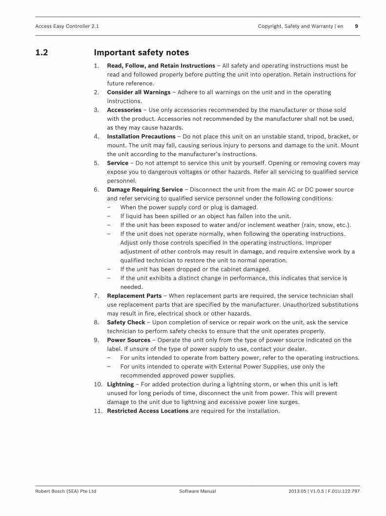
Important safety notes1. Read, Follow, and Retain Instructions – All safety and operating instructions must be
read and followed properly before putting the unit into operation. Retain instructions forfuture reference.
2. Consider all Warnings – Adhere to all warnings on the unit and in the operatinginstructions.
3. Accessories – Use only accessories recommended by the manufacturer or those soldwith the product. Accessories not recommended by the manufacturer shall not be used,as they may cause hazards.
4. Installation Precautions – Do not place this unit on an unstable stand, tripod, bracket, ormount. The unit may fall, causing serious injury to persons and damage to the unit. Mountthe unit according to the manufacturer’s instructions.
5. Service – Do not attempt to service this unit by yourself. Opening or removing covers mayexpose you to dangerous voltages or other hazards. Refer all servicing to qualified servicepersonnel.
6. Damage Requiring Service – Disconnect the unit from the main AC or DC power sourceand refer servicing to qualified service personnel under the following conditions:– When the power supply cord or plug is damaged.– If liquid has been spilled or an object has fallen into the unit.– If the unit has been exposed to water and/or inclement weather (rain, snow, etc.).– If the unit does not operate normally, when following the operating instructions.
Adjust only those controls specified in the operating instructions. Improperadjustment of other controls may result in damage, and require extensive work by aqualified technician to restore the unit to normal operation.
– If the unit has been dropped or the cabinet damaged.– If the unit exhibits a distinct change in performance, this indicates that service is
needed.7. Replacement Parts – When replacement parts are required, the service technician shall
use replacement parts that are specified by the manufacturer. Unauthorized substitutionsmay result in fire, electrical shock or other hazards.
8. Safety Check – Upon completion of service or repair work on the unit, ask the servicetechnician to perform safety checks to ensure that the unit operates properly.
9. Power Sources – Operate the unit only from the type of power source indicated on thelabel. If unsure of the type of power supply to use, contact your dealer.– For units intended to operate from battery power, refer to the operating instructions.– For units intended to operate with External Power Supplies, use only the
recommended approved power supplies.10. Lightning – For added protection during a lightning storm, or when this unit is left
unused for long periods of time, disconnect the unit from power. This will preventdamage to the unit due to lightning and excessive power line surges.
11. Restricted Access Locations are required for the installation.
1.2
Access Easy Controller 2.1 Copyright, Safety and Warranty | en 9
Robert Bosch (SEA) Pte Ltd Software Manual 2013.05 | V1.0.5 | F.01U.122.797
FCC information
Notice!
This device complies with Part 15 FCC Rules. Operation is subject to the following two
conditions: (1) this device may not cause harmful interference, and (2) this device must
accept any interference received including interference that may cause undesired operation.
1.3
10 en | Copyright, Safety and Warranty Access Easy Controller 2.1
2013.05 | V1.0.5 | F.01U.122.797 Software Manual Robert Bosch (SEA) Pte Ltd
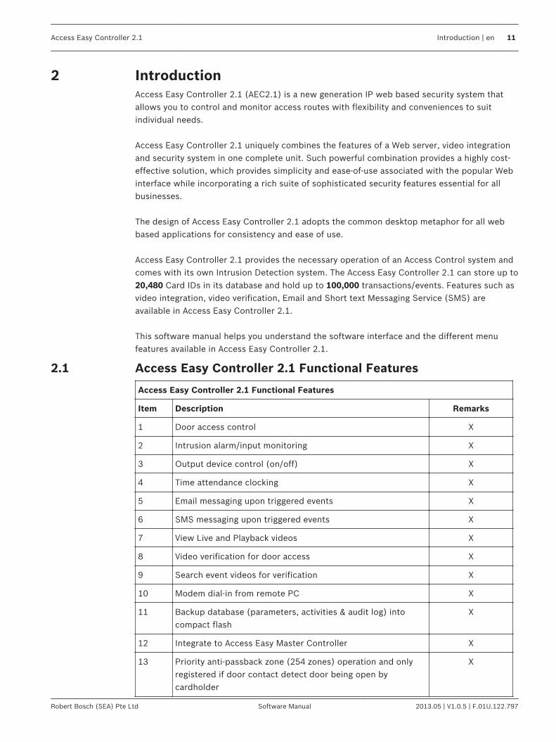
IntroductionAccess Easy Controller 2.1 (AEC2.1) is a new generation IP web based security system thatallows you to control and monitor access routes with flexibility and conveniences to suitindividual needs. Access Easy Controller 2.1 uniquely combines the features of a Web server, video integrationand security system in one complete unit. Such powerful combination provides a highly cost-effective solution, which provides simplicity and ease-of-use associated with the popular Webinterface while incorporating a rich suite of sophisticated security features essential for allbusinesses. The design of Access Easy Controller 2.1 adopts the common desktop metaphor for all webbased applications for consistency and ease of use. Access Easy Controller 2.1 provides the necessary operation of an Access Control system andcomes with its own Intrusion Detection system. The Access Easy Controller 2.1 can store up to20,480 Card IDs in its database and hold up to 100,000 transactions/events. Features such asvideo integration, video verification, Email and Short text Messaging Service (SMS) areavailable in Access Easy Controller 2.1. This software manual helps you understand the software interface and the different menufeatures available in Access Easy Controller 2.1.
Access Easy Controller 2.1 Functional Features
Access Easy Controller 2.1 Functional Features
Item Description Remarks
1 Door access control X
2 Intrusion alarm/input monitoring X
3 Output device control (on/off) X
4 Time attendance clocking X
5 Email messaging upon triggered events X
6 SMS messaging upon triggered events X
7 View Live and Playback videos X
8 Video verification for door access X
9 Search event videos for verification X
10 Modem dial-in from remote PC X
11 Backup database (parameters, activities & audit log) intocompact flash
X
12 Integrate to Access Easy Master Controller X
13 Priority anti-passback zone (254 zones) operation and onlyregistered if door contact detect door being open bycardholder
X
2
2.1
Access Easy Controller 2.1 Introduction | en 11
Robert Bosch (SEA) Pte Ltd Software Manual 2013.05 | V1.0.5 | F.01U.122.797
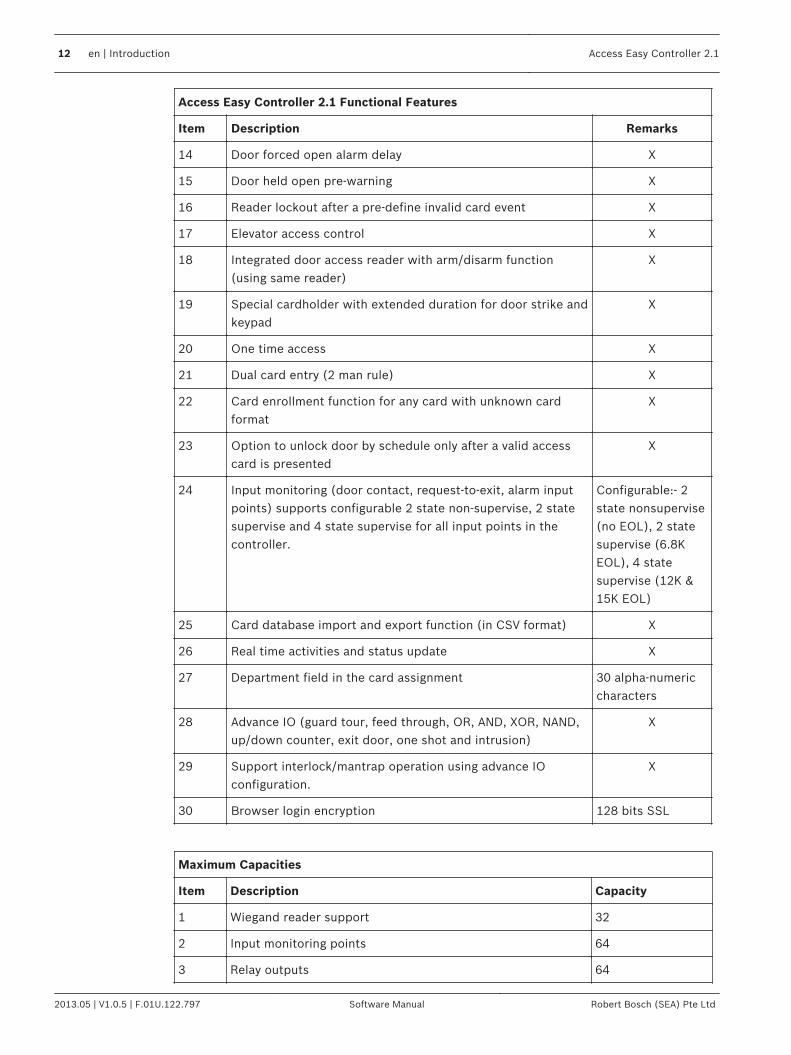
Access Easy Controller 2.1 Functional Features
Item Description Remarks
14 Door forced open alarm delay X
15 Door held open pre-warning X
16 Reader lockout after a pre-define invalid card event X
17 Elevator access control X
18 Integrated door access reader with arm/disarm function(using same reader)
X
19 Special cardholder with extended duration for door strike andkeypad
X
20 One time access X
21 Dual card entry (2 man rule) X
22 Card enrollment function for any card with unknown cardformat
X
23 Option to unlock door by schedule only after a valid accesscard is presented
X
24 Input monitoring (door contact, request-to-exit, alarm inputpoints) supports configurable 2 state non-supervise, 2 statesupervise and 4 state supervise for all input points in thecontroller.
Configurable:- 2state nonsupervise(no EOL), 2 statesupervise (6.8KEOL), 4 statesupervise (12K &15K EOL)
25 Card database import and export function (in CSV format) X
26 Real time activities and status update X
27 Department field in the card assignment 30 alpha-numericcharacters
28 Advance IO (guard tour, feed through, OR, AND, XOR, NAND,up/down counter, exit door, one shot and intrusion)
X
29 Support interlock/mantrap operation using advance IOconfiguration.
X
30 Browser login encryption 128 bits SSL
Maximum Capacities
Item Description Capacity
1 Wiegand reader support 32
2 Input monitoring points 64
3 Relay outputs 64
12 en | Introduction Access Easy Controller 2.1
2013.05 | V1.0.5 | F.01U.122.797 Software Manual Robert Bosch (SEA) Pte Ltd
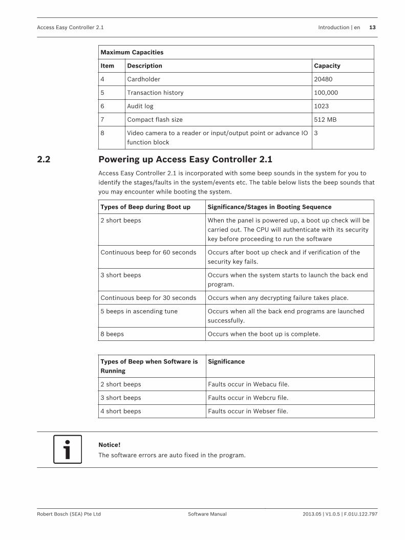
Maximum Capacities
Item Description Capacity
4 Cardholder 20480
5 Transaction history 100,000
6 Audit log 1023
7 Compact flash size 512 MB
8 Video camera to a reader or input/output point or advance IOfunction block
3
Powering up Access Easy Controller 2.1Access Easy Controller 2.1 is incorporated with some beep sounds in the system for you toidentify the stages/faults in the system/events etc. The table below lists the beep sounds thatyou may encounter while booting the system.
Types of Beep during Boot up Significance/Stages in Booting Sequence
2 short beeps When the panel is powered up, a boot up check will becarried out. The CPU will authenticate with its securitykey before proceeding to run the software
Continuous beep for 60 seconds Occurs after boot up check and if verification of thesecurity key fails.
3 short beeps Occurs when the system starts to launch the back endprogram.
Continuous beep for 30 seconds Occurs when any decrypting failure takes place.
5 beeps in ascending tune Occurs when all the back end programs are launchedsuccessfully.
8 beeps Occurs when the boot up is complete.
Types of Beep when Software isRunning
Significance
2 short beeps Faults occur in Webacu file.
3 short beeps Faults occur in Webcru file.
4 short beeps Faults occur in Webser file.
Notice!
The software errors are auto fixed in the program.
2.2
Access Easy Controller 2.1 Introduction | en 13
Robert Bosch (SEA) Pte Ltd Software Manual 2013.05 | V1.0.5 | F.01U.122.797

Overview of Access Easy Controller 2.1The basic AEC2.1 system consists of a single metal enclosure with three components: CPU, 4-Reader board, and Power Supply Unit (PSU). Space is provided for a 12-volt standby batteryto sustain the system in event of a power failure. The PSU in the controller has an input powerof 100~240 VAC. The enclosure is key locked and is equipped with a tamper switch to detect any tampering ofthe panel, and/or when the controller door is being opened.
Figure 3.1: AEC2.1 Main Enclosure
In its minimum configuration, an AEC2.1 system supports one 4-Reader board. The boardcomes with, 4 card reader, 8 input, and 8 output ports to support all necessary hardware(door lock/strike outputs, door contact inputs and request-to-exit inputs). A full AEC2.1system supports up to a maximum of 16 interface boards (eight 4-Reader boards and eight 8-IO boards). This allows the AEC2.1 system to support up to 32 card readers, 64 alarm typeinput and 64 controllable output points. CPU Board - The CPU board contains a microprocessor, RAM memory and all necessaryelectronic circuitry to interact with other circuit boards. The CPU board contains the hardwareand software needed to interface to an Ethernet-type network and to communicate with hostcomputers using TCP/IP protocol. 4-Reader Board - The 4-Reader board is an interface board for AEC2.1. The reader boardcontains all circuitry necessary to interface with, and operate, up to four card readers. Thereader board also provides wiring termination points for the readers, door strikes or magnetic
3
14 en | Overview of Access Easy Controller 2.1 Access Easy Controller 2.1
2013.05 | V1.0.5 | F.01U.122.797 Software Manual Robert Bosch (SEA) Pte Ltd

locks, door contacts and request-to-exit devices. The first interface board of the systemcommunicates with the CPU board via the RS232 channel. The subsequent interface boardsare linked through a multi-drop communication channel, RS485, to form the system. The PSUsupplies the required 12V DC power to the board. 8-Input-Output Board -The 8-IO board is an interface board for AEC2.1. The 8-IO boardprovides the necessary circuitry to monitor 8-alarm type (non-reader) inputs, and to control upto eight external devices, such as bells, fans, lights, etc. The board also provides wiringtermination points for the input and output devices. The first interface board of the systemcommunicates with the CPU board via the RS232 channel. The subsequent interface boardsare linked up through a multi-drop communication channel, RS485. The PSU supplies therequired 12V DC power to the board. Access Easy Extension - Access Easy Extension is a metal enclosure identical in size to thebasic AEC2.1. The Extension unit contains a Power Supply Unit, and space to install up to twoadditional 4-Reader boards and/or 8-IO boards. Space is provided for an optional 12V, 7AHstandby battery to sustain the system in time of power failure.
Notice!
AEC2.1 does not come with the 12V DC standby battery.
Access Easy Controller 2.1 Overview of Access Easy Controller 2.1 | en 15
Robert Bosch (SEA) Pte Ltd Software Manual 2013.05 | V1.0.5 | F.01U.122.797
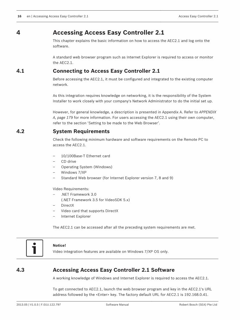
Accessing Access Easy Controller 2.1This chapter explains the basic information on how to access the AEC2.1 and log onto thesoftware. A standard web browser program such as Internet Explorer is required to access or monitorthe AEC2.1.
Connecting to Access Easy Controller 2.1Before accessing the AEC2.1, it must be configured and integrated to the existing computernetwork. As this integration requires knowledge on networking, it is the responsibility of the SystemInstaller to work closely with your company's Network Administrator to do the initial set up. However, for general knowledge, a description is presented in Appendix A. Refer to APPENDIXA, page 179 for more information. For users accessing the AEC2.1 using their own computer,refer to the section ‘Setting to be made to the Web Browser’.
System RequirementsCheck the following minimum hardware and software requirements on the Remote PC toaccess the AEC2.1. – 10/100Base-T Ethernet card– CD drive– Operating System (Windows)– Windows 7/XP– Standard Web browser (for Internet Explorer version 7, 8 and 9) Video Requirements:– .NET Framework 3.0
(.NET Framework 3.5 for VideoSDK 5.x)– DirectX– Video card that supports DirectX– Internet Explorer The AEC2.1 can be accessed after all the preceding system requirements are met.
Notice!
Video integration features are available on Windows 7/XP OS only.
Accessing Access Easy Controller 2.1 SoftwareA working knowledge of Windows and Internet Explorer is required to access the AEC2.1. To get connected to AEC2.1, launch the web browser program and key in the AEC2.1's URLaddress followed by the <Enter> key. The factory default URL for AEC2.1 is 192.168.0.41.
4
4.1
4.2
4.3
16 en | Accessing Access Easy Controller 2.1 Access Easy Controller 2.1
2013.05 | V1.0.5 | F.01U.122.797 Software Manual Robert Bosch (SEA) Pte Ltd

The screen below shows an example of the web browser with the default URL address for theAEC2.1.
Figure 4.1: AEC2.1 Default URL address
Note: All screens are presented in Internet Explorer 7.0. This will bring up the login page.
Logging into Access Easy Controller 2.1The login screen appears as shown below.
This User Login dialog box provides a security control that protects the AEC2.1 fromunauthorized access. Enter your user id and password in the User Name and Password fieldto gain access to the AEC2.1. Select the required GUI language from the language dropdown. The system allows up to 8 users to logon the same AEC2.1 using different computers.
Notice!
The User ID and Password are case-sensitive and can be changed.
4.4
Access Easy Controller 2.1 Accessing Access Easy Controller 2.1 | en 17
Robert Bosch (SEA) Pte Ltd Software Manual 2013.05 | V1.0.5 | F.01U.122.797
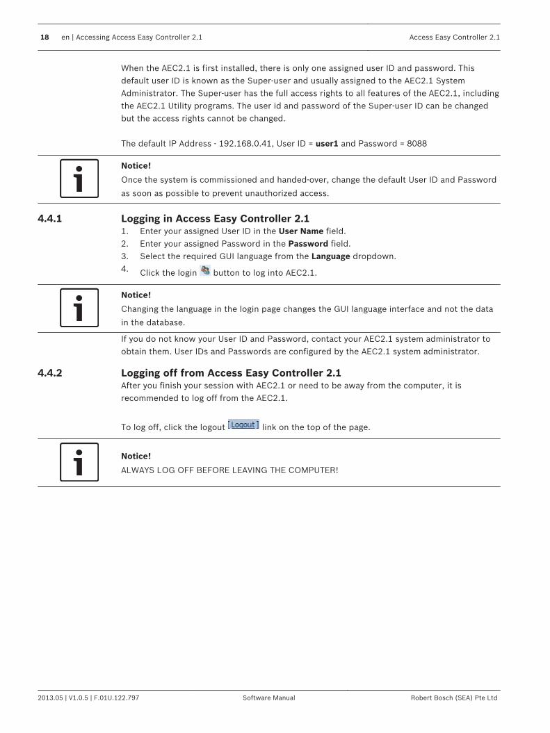
When the AEC2.1 is first installed, there is only one assigned user ID and password. Thisdefault user ID is known as the Super-user and usually assigned to the AEC2.1 SystemAdministrator. The Super-user has the full access rights to all features of the AEC2.1, includingthe AEC2.1 Utility programs. The user id and password of the Super-user ID can be changedbut the access rights cannot be changed. The default IP Address - 192.168.0.41, User ID = user1 and Password = 8088
Notice!
Once the system is commissioned and handed-over, change the default User ID and Password
as soon as possible to prevent unauthorized access.
Logging in Access Easy Controller 2.11. Enter your assigned User ID in the User Name field.2. Enter your assigned Password in the Password field.3. Select the required GUI language from the Language dropdown.4. Click the login button to log into AEC2.1.
Notice!
Changing the language in the login page changes the GUI language interface and not the data
in the database.
If you do not know your User ID and Password, contact your AEC2.1 system administrator toobtain them. User IDs and Passwords are configured by the AEC2.1 system administrator.
Logging off from Access Easy Controller 2.1After you finish your session with AEC2.1 or need to be away from the computer, it isrecommended to log off from the AEC2.1.
To log off, click the logout link on the top of the page.
Notice!
ALWAYS LOG OFF BEFORE LEAVING THE COMPUTER!
4.4.1
4.4.2
18 en | Accessing Access Easy Controller 2.1 Access Easy Controller 2.1
2013.05 | V1.0.5 | F.01U.122.797 Software Manual Robert Bosch (SEA) Pte Ltd

Installing ActiveX and VideoSDKInstall ActiveX and VideoSDK to access the video features of AEC2.1. The ActiveX and Video SDK is installed automatically when the AEC2.1 system is set. If theVideo SDK is not installed automatically then you can install it from the Utility CD or retrievethe files from the VideoSDK page. Refer to Video SDK, page 161 in Advance settings for moreinformation. Tips: If the ActiveX control is not shown correctly after auto-installation of ActiveX / VideoSDK, please restart the browser and try again. If problem still persists, please follow theUninstall Procedure for ActiveX and VideoSDK, page 20 and proceed with manual/autoinstallation. Refer to the section below for installing VideoSDK from the utility CD.
Notice!
The system will auto install VideoSDK only if a camera is configured.
Installation Procedure for VideoSDKThe steps below will guide you through the installation of the Video SDK. 1. Place the CD in the CD-ROM and open the folder BOSCH VideoSDK. In the BOSCH
VideoSDK folder look for the .exe file in the installer folder.2. Double click the .exe file. The screen below appears. Click the Next button to proceed
with the installation.
5
5.1
Access Easy Controller 2.1 Installing ActiveX and VideoSDK | en 19
Robert Bosch (SEA) Pte Ltd Software Manual 2013.05 | V1.0.5 | F.01U.122.797

3. Follow the instructions in the install Shield window to complete the installation. After theinstallation is completed successfully the screen below appears.
This completes the BOSCH VideoSDK installation.
Uninstall Procedure for ActiveX and VideoSDKFollow the procedures below to uninstall ActiveX and VideoSDK based on the version ofVideoSDK. Please close all the browsers and any other applications that is using ActiveX and/orVideoSDK.
Procedure for Video SDK 4.xUninstall AEC ActiveX– For 64 bit system:
Go to “C:\Program Files (x86)\Internet Explorer” and delete AECVideoActiveX.ocx– For 32 bit system:
Go to “C:\Program Files\Internet Explorer” and delete AECVideoActiveX.ocxUninstall VideoSDK 4.x– In ‘Control Panel’ > ‘Programs’ > ‘Programs and Features’, remove/uninstall ‘Bosch Video
SDK Runtime Library 4.X’
Procedure for Video SDK 5.xUninstall AEC ActiveX1. Go to '(OS installation Drive)\ProgramData\BOSCH\AEC2.1' folder. Run Uninstall
ActiveX.bat as Administrator.
5.2
20 en | Installing ActiveX and VideoSDK Access Easy Controller 2.1
2013.05 | V1.0.5 | F.01U.122.797 Software Manual Robert Bosch (SEA) Pte Ltd

2. Delete '(OS installation Drive)\ProgramData\BOSCH\AEC2.1' folder. (Please make sureBrowser is closed).
Notice!
If ProgramData folder is not visible, make sure that you have enabled the option to show
hidden files and folders. It can be done in Windows Explorer, press 'Alt' > 'Tools' > 'Folder
options...' and select 'Show hidden files, folders and drives'.
Uninstall VideoSDK– In ‘Control Panel’ > ‘Programs’ > ‘Programs and Features’, remove/uninstall ‘Bosch Video
SDK 5.X’
Access Easy Controller 2.1 Installing ActiveX and VideoSDK | en 21
Robert Bosch (SEA) Pte Ltd Software Manual 2013.05 | V1.0.5 | F.01U.122.797
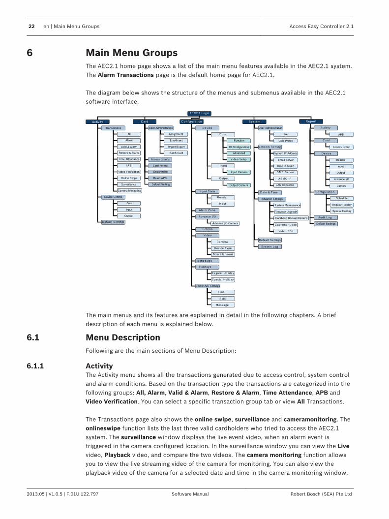
Main Menu GroupsThe AEC2.1 home page shows a list of the main menu features available in the AEC2.1 system.The Alarm Transactions page is the default home page for AEC2.1. The diagram below shows the structure of the menus and submenus available in the AEC2.1software interface.
AEC2.1 Login
Activity Card Configu ration System
Date & Time
Network Setting
Device
Device Control
Advance I/O
A larm Zone
Schedules
Holidays
Report
Activ ity
Card
Dev ice
Configura tion
Import/Export
D ia l In User
Crite ria
Video
Camera
Dev ice Type
M isce llaneous
Door
Input
Output
Function
Advanced
Video Setup
SMS Server
Customer Logo
Default Settings
Input S ta te
Reader
Input
Regular Ho liday
Spec ia l Ho liday
AEMC IP
Video SDK
Default Settings
System Log
Audit Log
IO Configuration
Time Attendance
APB
Output
Input
Door
Restore & Alarm
Valid & Alarm
Alarm
All
Transactions Card Administration
Assignment
Enrollment
Batch Card
Access Groups
Card Format
Department
Reset APB
Default Setting
Database Backup/Restore
Firmware Upgrade
System Maintenance
Advance Settings
Email Server
System IP Address
User Administration
Online Swipe
Surveillance
Video Verification
Camera Monitoring
Input Camera
Output Camera
SMS
Message
Email/SMS Settings
User Profile
User APB
Access Group
Reader
Input
Output
Advance I/O
Camera
Schedule
Regular Holiday
Special Holiday
Default Settings Advance I/O Camera
LAN Converter
The main menus and its features are explained in detail in the following chapters. A briefdescription of each menu is explained below.
Menu DescriptionFollowing are the main sections of Menu Description:
ActivityThe Activity menu shows all the transactions generated due to access control, system controland alarm conditions. Based on the transaction type the transactions are categorized into thefollowing groups: All, Alarm, Valid & Alarm, Restore & Alarm, Time Attendance, APB andVideo Verification. You can select a specific transaction group tab or view All Transactions. The Transactions page also shows the online swipe, surveillance and cameramonitoring. Theonlineswipe function lists the last three valid cardholders who tried to access the AEC2.1system. The surveillance window displays the live event video, when an alarm event istriggered in the camera configured location. In the surveillance window you can view the Livevideo, Playback video, and compare the two videos. The camera monitoring function allowsyou to view the live streaming video of the camera for monitoring. You can also view theplayback video of the camera for a selected date and time in the camera monitoring window.
6
6.1
6.1.1
22 en | Main Menu Groups Access Easy Controller 2.1
2013.05 | V1.0.5 | F.01U.122.797 Software Manual Robert Bosch (SEA) Pte Ltd

The video verification function enables automatic live video display of the access point forcomparison with cardholder’s photo for the operator to grant access or deny access to thecardholder. The Activity menu relates to the manual control of the system hardware and consists of DoorControl, Input Control and Output Control.
CardThe card menu relates to the card parameter set up, such as Card Number, Cardholder’sname, Cardholder’s photo etc including the right to Arm/Disarm an alarm zone. The card menu also relates to the Access Groups that allows to categorize the Card Readersinto different Access Groups for Cardholder’s access rights. A cardholder can have accessrights for a maximum of two access groups. In the card menu option you can create Card Formats, Departments and Reset the AntiPassback settings for a cardholder.
ConfigurationThe configuration menu relates to the door settings and camera settings of the system. In thecamera settings a maximum of three cameras can be configured to each reader or input/output point or advance IO function block. In the card menu option you can create alarm zones, criteria settings, configure Email, SMSand Message settings. Advance IO setup is used to enable the rerouting of physical or logical information from oneoperation to another. In the configuration menu you can add device types and configure cameras to the AEC2.1system. The auto detect camera option lists the available cameras. Schedules are used to set-up time intervals for use in access system and hardware control.Holidays are used to define and assign programmable holiday dates.
SystemUser ID’s and Password including access rights to the various menu items are set in thesystem menu. You can configure the Panel IP address, Dial In settings, and the AEMC IPsettings. The system menu allows you to set the date and time of the panel. Database Backup is used to backup (write) all databases into the flash memory of thecontroller and further download to the hard disk of a PC. You can define a time in the AEC2.1to perform an automatic backup to the flash memory. The database backup is also used fordatabase recovery. Firmware upgrade is used to upgrade firmware or program upgrade. Video update is used toupdate the video versions.
6.1.2
6.1.3
6.1.4
Access Easy Controller 2.1 Main Menu Groups | en 23
Robert Bosch (SEA) Pte Ltd Software Manual 2013.05 | V1.0.5 | F.01U.122.797

Reboot Panel function is used to reboot the AEC2.1 system. A reboot is usually performedafter resetting the AEC2.1 IP Address or during a firmware upgrade. Shutdown Panel functionis used to shutdown the AEC2.1 system. A shutdown is usually performed after hardwareupgrades.
ReportThis menu item allows you to print reports based on transactions, cardholders violating theAPB settings, access groups, schedules, user log, Input points, camera, holidays etc. You can provide a main header and sub headers for the reports generated from the AEC2.1system.
LogoutThe Logout option is used to log off from AEC2.1 system.
Navigating through Access Easy Controller 2.1 PageClick the main menu followed by the sub menus to access the web page of the functionsselected.
Usage of the ButtonsThe table below shows the functions of the action buttons available in AEC2.1 webpage.
Button Description
The save button saves the current settings to the (Dynamic RAM) DRAM andrefreshes the current web page
The add button performs the following functions:-– carries out the addition process– adds selected parameter to the list window
The delete button performs the following functions:-– deletes all configurable parameters and sets it to default– removes selected parameter from the list window
The previous button performs the following functions– does not save the settings made on the current screen and– brings up the previous screen
The edit button, edits the current parameter settings
The move left button, moves a selected parameter from the right list windowto the left list window
The move right button, moves a selected parameter from the left list windowto the right list window
The reboot panel button, reboots the AEC2.1 system
The shutdown button, shuts down the AEC2.1 system
Time synchronization button, synchronizes the AEC2.1 system time to theserver time or PC time
6.1.5
6.1.6
6.2
6.3
24 en | Main Menu Groups Access Easy Controller 2.1
2013.05 | V1.0.5 | F.01U.122.797 Software Manual Robert Bosch (SEA) Pte Ltd
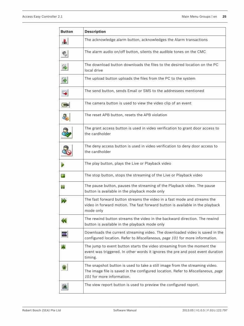
Button Description
The acknowledge alarm button, acknowledges the Alarm transactions
The alarm audio on/off button, silents the audible tones on the CMC
The download button downloads the files to the desired location on the PClocal drive
The upload button uploads the files from the PC to the system
The send button, sends Email or SMS to the addressees mentioned
The camera button is used to view the video clip of an event
The reset APB button, resets the APB violation
The grant access button is used in video verification to grant door access tothe cardholder
The deny access button is used in video verification to deny door access tothe cardholder
The play button, plays the Live or Playback video
The stop button, stops the streaming of the Live or Playback video
The pause button, pauses the streaming of the Playback video. The pausebutton is available in the playback mode only
The fast forward button streams the video in a fast mode and streams thevideo in forward motion. The fast forward button is available in the playbackmode only
The rewind button streams the video in the backward direction. The rewindbutton is available in the playback mode only
Downloads the current streaming video. The downloaded video is saved in theconfigured location. Refer to Miscellaneous, page 101 for more information.
The jump to event button starts the video streaming from the moment theevent was triggered. In other words it ignores the pre and post event durationtiming.
The snapshot button is used to take a still image from the streaming video.The image file is saved in the configured location. Refer to Miscellaneous, page101 for more information.
The view report button is used to preview the configured report.
Access Easy Controller 2.1 Main Menu Groups | en 25
Robert Bosch (SEA) Pte Ltd Software Manual 2013.05 | V1.0.5 | F.01U.122.797

ActivityThe Activity menu relates to the transactions generated by the AEC2.1 system and the videofeatures available in AEC2.1. The activity menu also relates to the manual control of thesystem hardware. The different features of the activity menu are explained in the following sections. The Activity main menu consists of the following submenus: – Transactions– Device Control– Default Settings The three submenus are explained in detail in the following pages.
TransactionsThe transactions submenu lists all the transactions or events triggered by the AEC2.1. Everyactivity transaction such as Door Forced Open, Door Held Open, Access Granted, AccessDenied etc. are captured by AEC2.1 and displayed on the transactions web page in real-timemode with the transaction occurrence date and time. The transactions window consists of two window panes, the left pane and the right pane. Theleft pane displays the transactions performed by AEC2.1 and the right pane displays theonline swipe, surveillance and camera monitoring features. The transactions are categorized into different groups based on the event triggered or actionsperformed on the AEC2.1. The transactions are categorized as follows: All, Alarm, Valid &Alarm, Restore & Alarm, Time Attendance, APB and Video Verification. You can select aspecific transaction event or view all the transactions by selecting the All tab. AEC2.1 can store up to 100,000 activity transactions and the Alarm transactions window isthe default screen for AEC2.1. Note: The default view of the transaction screen can be changed in the default settings pageof the activity menu. Refer to Activity - Default Settings, page 47 for more details. The screen below shows the transaction window with the All tab selected. You can select atransaction group by selecting the transaction group tab you want to view.
7
7.1
26 en | Activity Access Easy Controller 2.1
2013.05 | V1.0.5 | F.01U.122.797 Software Manual Robert Bosch (SEA) Pte Ltd
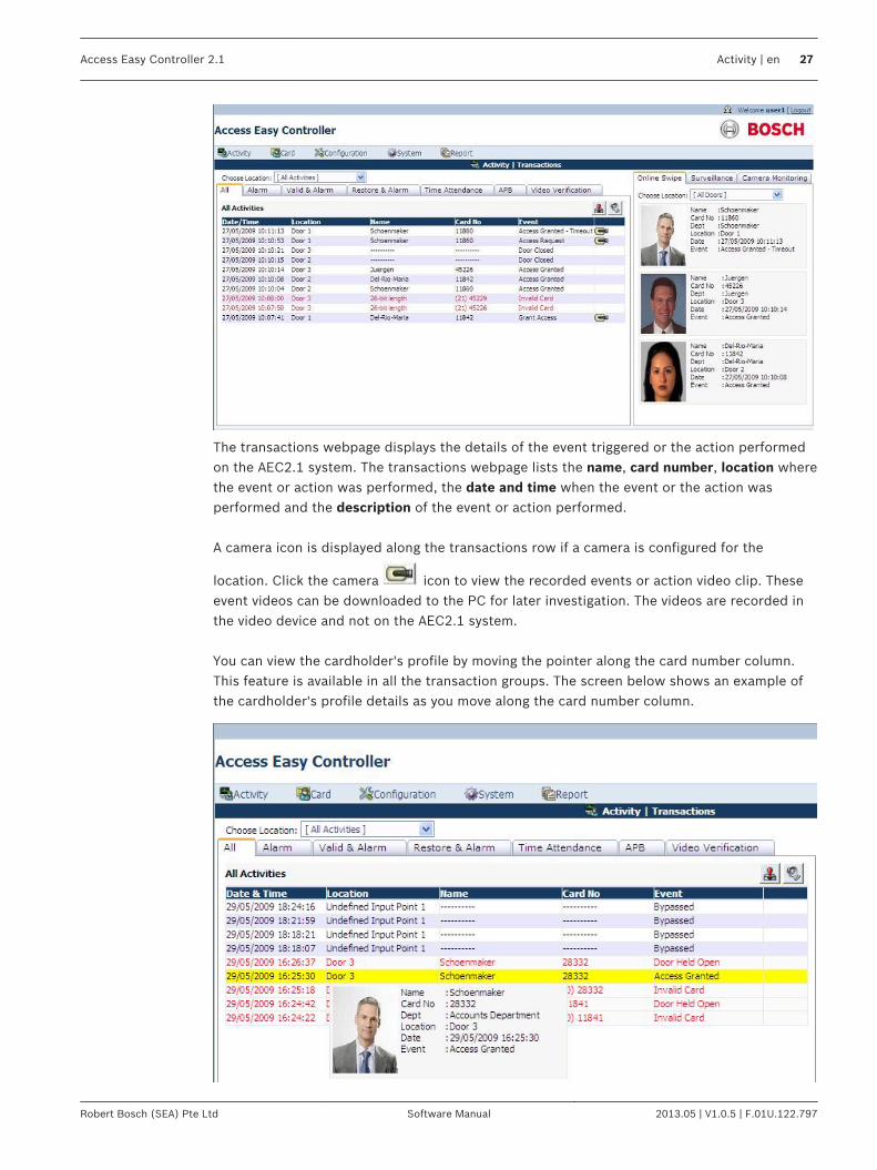
The transactions webpage displays the details of the event triggered or the action performedon the AEC2.1 system. The transactions webpage lists the name, card number, location wherethe event or action was performed, the date and time when the event or the action wasperformed and the description of the event or action performed. A camera icon is displayed along the transactions row if a camera is configured for the
location. Click the camera icon to view the recorded events or action video clip. Theseevent videos can be downloaded to the PC for later investigation. The videos are recorded inthe video device and not on the AEC2.1 system. You can view the cardholder's profile by moving the pointer along the card number column.This feature is available in all the transaction groups. The screen below shows an example ofthe cardholder's profile details as you move along the card number column.
Access Easy Controller 2.1 Activity | en 27
Robert Bosch (SEA) Pte Ltd Software Manual 2013.05 | V1.0.5 | F.01U.122.797
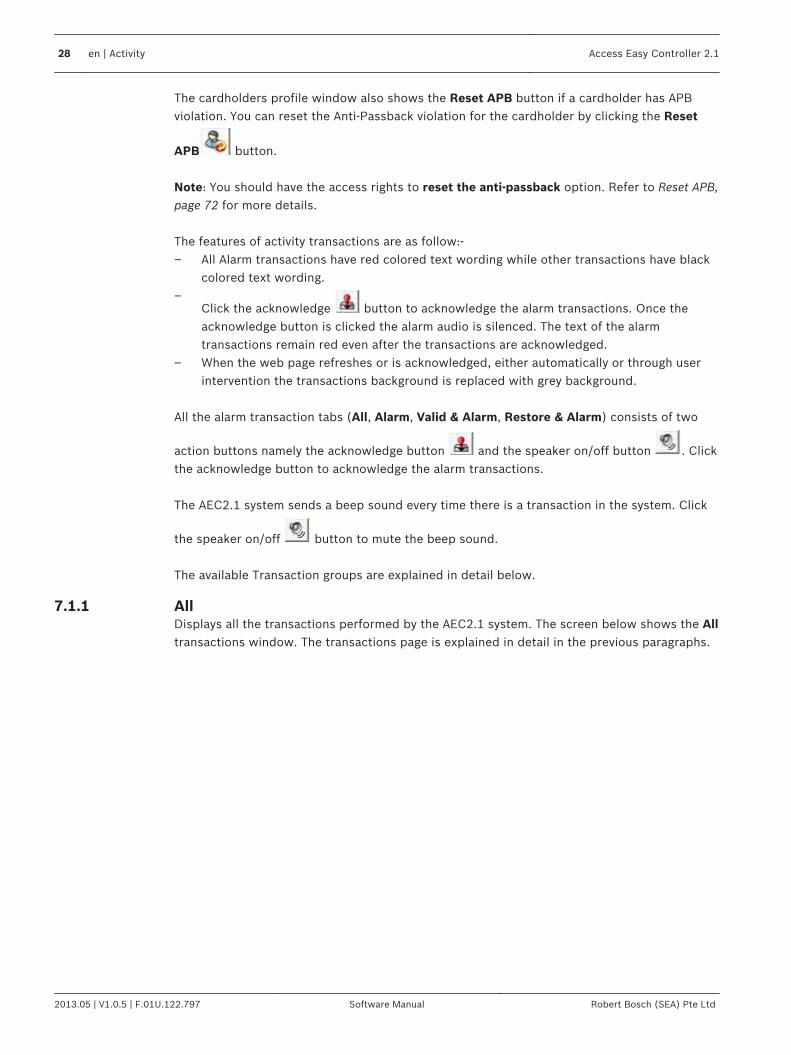
The cardholders profile window also shows the Reset APB button if a cardholder has APBviolation. You can reset the Anti-Passback violation for the cardholder by clicking the Reset
APB button. Note: You should have the access rights to reset the anti-passback option. Refer to Reset APB,page 72 for more details. The features of activity transactions are as follow:-– All Alarm transactions have red colored text wording while other transactions have black
colored text wording.–
Click the acknowledge button to acknowledge the alarm transactions. Once theacknowledge button is clicked the alarm audio is silenced. The text of the alarmtransactions remain red even after the transactions are acknowledged.
– When the web page refreshes or is acknowledged, either automatically or through userintervention the transactions background is replaced with grey background.
All the alarm transaction tabs (All, Alarm, Valid & Alarm, Restore & Alarm) consists of two
action buttons namely the acknowledge button and the speaker on/off button . Clickthe acknowledge button to acknowledge the alarm transactions. The AEC2.1 system sends a beep sound every time there is a transaction in the system. Click
the speaker on/off button to mute the beep sound. The available Transaction groups are explained in detail below.
AllDisplays all the transactions performed by the AEC2.1 system. The screen below shows the Alltransactions window. The transactions page is explained in detail in the previous paragraphs.
7.1.1
28 en | Activity Access Easy Controller 2.1
2013.05 | V1.0.5 | F.01U.122.797 Software Manual Robert Bosch (SEA) Pte Ltd

The Choose Location dropdown at the top of the page lists all the doors configured to thesystem. You can configure a group of doors as a set in Setting - Door Group… option availablein the choose location dropdown. Select Setting - Door Group… from the Choose Locationdropdown as shown below.The screen below appears to select the doors to be added to the Door Group.Select the check box corresponding to the respective doors which has to be configured in the
Door Group set. Click the save button to save the locations in the door group. Select theAll Items option if you want to select all the doors in the locations list to the door group. After
selecting the required doors click the save button to save the settings. Click the back
button to cancel the settings and return to the transactions page.
Notice!
The configured location is user based and is available to the user who configured the door
group.
After saving the settings the web page returns to the Transactions main page. Select alocation from the Choose Location dropdown to view the transactions/events of the AEC2.1system at the selected location. In the All transactions window, all the alarm transactions have red colored text while othertransactions have black colored text.
Access Easy Controller 2.1 Activity | en 29
Robert Bosch (SEA) Pte Ltd Software Manual 2013.05 | V1.0.5 | F.01U.122.797
AlarmDisplays the alarm events triggered by the system. Examples of Alarm transactions includeAccess Denied, Door Held Open, Panel Tamper, Duress etc. For a detailed list on Alarmtransaction, refer to Activity Transactions. When any of the Alarm Activity transactions is transacted, an alert audio tone is sent to theCentral Monitoring Computer (CMC). Ensure that the CMC's audio system is in working orderand the volume is set to a reasonable level. The working procedure and the features available in Alarm transaction group is the same asexplained in the All transactions group. Refer to All, page 28 for more information about thesoftware interface and the features available in the Alarm tab.
Valid & AlarmDisplays transactions performed by the system. Examples of Valid transactions include AccessGranted, Turn On, Disarmed, Duration On etc. For a detailed list on Valid transaction, refer toValid Activity, page 193. The working procedure and the features available in Valid & Alarm is the same as explained inthe All transactions group. Refer to All, page 28 for more information about the softwareinterface and the features available in the Valid & Alarm tab.
Restore & AlarmDisplays the Alarm and Restored transactions performed by the system. Examples of Restoredtransactions include Door Closed, Tamper Restored, Alarm Restored and PowerRestored.For a detailed list on Restored transaction, refer to Restore Activity, page 193. The working procedure and the features available in Restore & Alarm is the same as explainedin the All transactions group. Refer to All, page 28 for more information about the softwareinterface and the features available in the alarm tab.
Time AttendanceDisplays only Time Clocking transactions. Examples of Time Attendance transactions includeClock In and Clock Out. The working procedure and the features available in Time Attendance is the same asexplained in the All transactions group. Refer to All, page 28 for more information about thesoftware interface and the features available in the time attendance tab.
APBDisplays the list of cardholder's name who are currently present in the APB zone. Refer to theReset APB, page 72 for more information about Anti Passback. The APB Zone dropdown at the top of the page lists all the APB Zones configured in thesystem. Select a Zone from the Alarm Zone dropdown to view the list of cardholder’s who arein the selected APB zone.
7.1.2
7.1.3
7.1.4
7.1.5
7.1.6
30 en | Activity Access Easy Controller 2.1
2013.05 | V1.0.5 | F.01U.122.797 Software Manual Robert Bosch (SEA) Pte Ltd
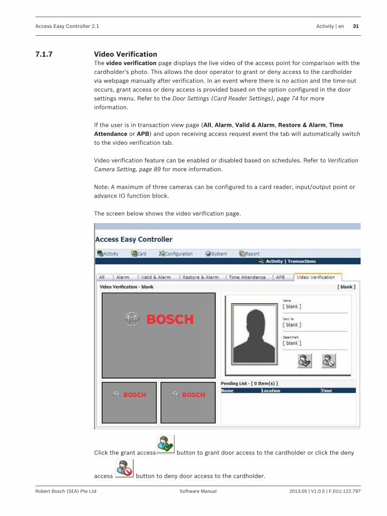
Video VerificationThe video verification page displays the live video of the access point for comparison with thecardholder's photo. This allows the door operator to grant or deny access to the cardholdervia webpage manually after verification. In an event where there is no action and the time-outoccurs, grant access or deny access is provided based on the option configured in the doorsettings menu. Refer to the Door Settings (Card Reader Settings), page 74 for moreinformation. If the user is in transaction view page (All, Alarm, Valid & Alarm, Restore & Alarm, TimeAttendance or APB) and upon receiving access request event the tab will automatically switchto the video verification tab. Video verification feature can be enabled or disabled based on schedules. Refer to VerificationCamera Setting, page 89 for more information. Note: A maximum of three cameras can be configured to a card reader, input/output point oradvance IO function block. The screen below shows the video verification page.
Click the grant access button to grant door access to the cardholder or click the deny
access button to deny door access to the cardholder.
7.1.7
Access Easy Controller 2.1 Activity | en 31
Robert Bosch (SEA) Pte Ltd Software Manual 2013.05 | V1.0.5 | F.01U.122.797

This view shows the Live video of all the cameras configured to the reader. Double click onthe main video to view the full screen video or select any small video at the bottom to view thevideo in the main window. The pending list at the bottom of the video verification tab lists the name and location of thecardholder waiting for door access at different configured locations. Select each cardholderfrom the list to grant or deny door access. The number of items is equal to the number ofcardholders waiting for access rights. The grant access and deny access button will be disabled if the cardholder in the pending listhas been granted or denied access by another user. Before the cardholder in the pending list is granted or denied access, another user flashes thecard on the same location it will overwrite the existing cardholder details in the pending list tothe latest cardholder details. The current date and time is displayed at the top right of the page and the location of thecardholder waiting for door access is described besides the video verification text. A samplevideo verification window is shown below for reference.
In the earlier example as soon as Maria is granted or denied access her transaction can beviewed in the online swipe window and Sachin’s video clips are displayed in the videoverification window.
Online SwipeThe online swipe function lists the last three valid cardholders with photo who tried to accessthe system. The online swipe tab lists the cardholder's profile and a button to reset APB if thecardholder has APB violation. The screen below shows the Online Swipe window.
7.1.8
32 en | Activity Access Easy Controller 2.1
2013.05 | V1.0.5 | F.01U.122.797 Software Manual Robert Bosch (SEA) Pte Ltd

In the online swipe window all the alarm transactions and access denied events, APB violatingtransactions are represented with a red border along the cardholder’s photo as shown below.The invalid card actions are not recorded or represented in the online swipe window.
Access Easy Controller 2.1 Activity | en 33
Robert Bosch (SEA) Pte Ltd Software Manual 2013.05 | V1.0.5 | F.01U.122.797
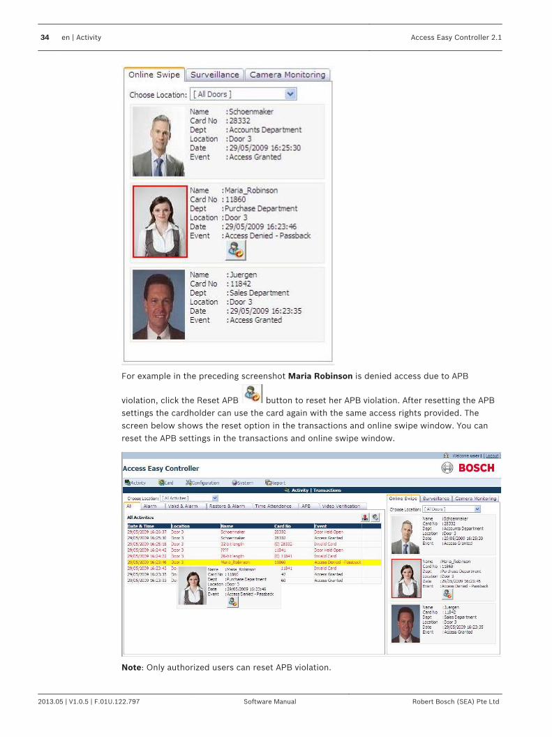
For example in the preceding screenshot Maria Robinson is denied access due to APB
violation, click the Reset APB button to reset her APB violation. After resetting the APBsettings the cardholder can use the card again with the same access rights provided. Thescreen below shows the reset option in the transactions and online swipe window. You canreset the APB settings in the transactions and online swipe window.
Note: Only authorized users can reset APB violation.
34 en | Activity Access Easy Controller 2.1
2013.05 | V1.0.5 | F.01U.122.797 Software Manual Robert Bosch (SEA) Pte Ltd

This tab also provides an option to see the list of cardholder's who tried to access the systemat a particular door or group of doors. The Choose Location dropdown at the top of the page lists all the doors configured to theAEC2.1 system. You can configure a group of doors as one door group in Setting - DoorGroup… option available in the Choose Location dropdown. Select Setting - Door Group…from the Choose Location dropdown as shown below. The screen below pops up to select the doors to be added to the Door Group.Select the check box corresponding to the respective doors which has to be configured in the
Door Group set. Click the save button to save the locations in the door group. Select theAll Items option if you want to select all the doors in the location list to the door group. After
selecting the required doors click the save button to save the settings. Click the back
button to cancel the settings and return to the transactions page.
SurveillanceWhen an alarm event is triggered the surveillance window will automatically display thesurveillance Live video of the event location and the event details, if a surveillance camera isconfigured for the event location. In the surveillance window you can view the Live andPlayback videos of the configured cameras. You can also compare the Live and Playbackvideos in the surveillance window. The surveillance camera for door is set in the door settingsoption, refer to Door Settings (Card Reader Settings), page 74 for more information.
Notice!
If an optional camera is configured for the event location without configuring a surveillance
camera, it is considered as no surveillance camera is configured for the event location.
The screen below shows the surveillance screen in the Live mode.
7.1.9
Access Easy Controller 2.1 Activity | en 35
Robert Bosch (SEA) Pte Ltd Software Manual 2013.05 | V1.0.5 | F.01U.122.797

The table below lists the function buttons available in the surveillance window of the AEC2.1system. The buttons mentioned in the table below have the same functionality in all the videofeature tabs.
Button Function
Compares the Live and Playback video
Toggles between the Live and Playback video
Plays the video. Starts the video streaming
Pauses the video streaming and this option is available in the Playback modeonly
Stops the video display or video streaming
The rewind button streams the video in the backward direction. The rewindbutton is available in the Playback mode only
The fast forward button streams the video in a fast mode and streams thevideo in forward motion. The fast forward button is available in the Playbackmode only
Downloads the current streaming video. The downloaded video is saved in theconfigured location. Refer to Miscellaneous, page 101 for more information.
36 en | Activity Access Easy Controller 2.1
2013.05 | V1.0.5 | F.01U.122.797 Software Manual Robert Bosch (SEA) Pte Ltd
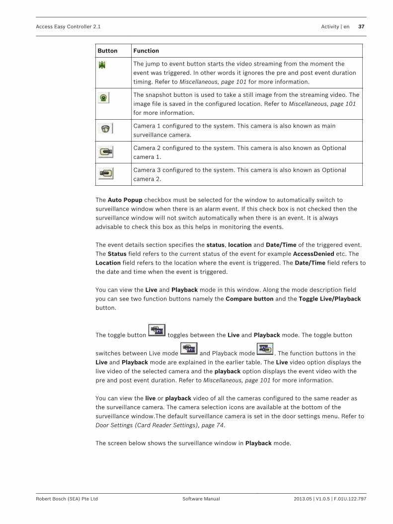
Button Function
The jump to event button starts the video streaming from the moment theevent was triggered. In other words it ignores the pre and post event durationtiming. Refer to Miscellaneous, page 101 for more information.
The snapshot button is used to take a still image from the streaming video. Theimage file is saved in the configured location. Refer to Miscellaneous, page 101for more information.
Camera 1 configured to the system. This camera is also known as mainsurveillance camera.
Camera 2 configured to the system. This camera is also known as Optionalcamera 1.
Camera 3 configured to the system. This camera is also known as Optionalcamera 2.
The Auto Popup checkbox must be selected for the window to automatically switch tosurveillance window when there is an alarm event. If this check box is not checked then thesurveillance window will not switch automatically when there is an event. It is alwaysadvisable to check this box as this helps in monitoring the events. The event details section specifies the status, location and Date/Time of the triggered event.The Status field refers to the current status of the event for example AccessDenied etc. TheLocation field refers to the location where the event is triggered. The Date/Time field refers tothe date and time when the event is triggered. You can view the Live and Playback mode in this window. Along the mode description fieldyou can see two function buttons namely the Compare button and the Toggle Live/Playbackbutton.
The toggle button toggles between the Live and Playback mode. The toggle button
switches between Live mode and Playback mode . The function buttons in theLive and Playback mode are explained in the earlier table. The Live video option displays thelive video of the selected camera and the playback option displays the event video with thepre and post event duration. Refer to Miscellaneous, page 101 for more information. You can view the live or playback video of all the cameras configured to the same reader asthe surveillance camera. The camera selection icons are available at the bottom of thesurveillance window.The default surveillance camera is set in the door settings menu. Refer toDoor Settings (Card Reader Settings), page 74. The screen below shows the surveillance window in Playback mode.
Access Easy Controller 2.1 Activity | en 37
Robert Bosch (SEA) Pte Ltd Software Manual 2013.05 | V1.0.5 | F.01U.122.797

At the bottom of the surveillance window you will see the play, stop, snapshot and exportvideo clip buttons. Click the play button to start the video streaming, stop button to end thevideo streaming, snapshot button to capture a still image from the streaming video and exportvideo clip to download the streaming video. The Playback mode consists of more function buttons namely pause, rewind, forward andjump to event. Click the pause button to pause the video streaming, rewind button to streamthe video in the backward direction, forward button to stream the video in the forwarddirection, jump to event button to start the video streaming from the moment the event wastriggered.
Notice!
The pause button , rewind button , forward button and jump to event are
available in Playback mode only.
A compare option is provided in the surveillance tab to compare the live and playback video
of the selected camera. Click the compare button to compare the Live video andPlayback video simultaneously. The playback video starts and ends the video display with thepre and post timer settings. Refer to Miscellaneous, page 101 for setting the pre and posttimer settings. The screen below shows the compare window.
38 en | Activity Access Easy Controller 2.1
2013.05 | V1.0.5 | F.01U.122.797 Software Manual Robert Bosch (SEA) Pte Ltd

The function buttons have the same functionality as explained in the earlier paragraphs. Click
the back button to return to the Transactions | surveillance page. Note: Double click on the video in the Live and Playback mode to view the enlarged video. Note: The exported videos can be viewed using the player available in BOSCH VideoSDKfolder on the utility CD.
Camera MonitoringThe camera monitoring tab is used to monitor the cameras configured to the AEC2.1 system.When you select the camera monitoring tab you can view the live or the playback video for aselected date and time. The screen below shows the camera monitoring screen in the Live mode.
7.1.10
Access Easy Controller 2.1 Activity | en 39
Robert Bosch (SEA) Pte Ltd Software Manual 2013.05 | V1.0.5 | F.01U.122.797
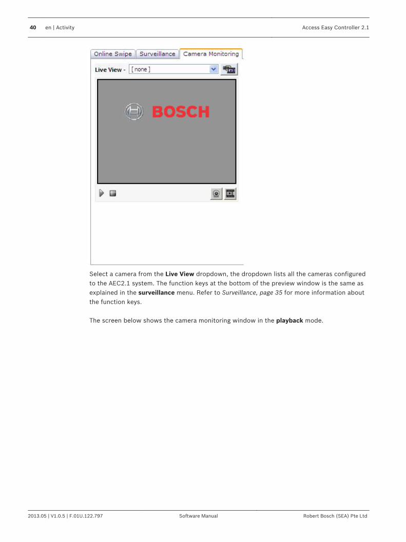
Select a camera from the Live View dropdown, the dropdown lists all the cameras configuredto the AEC2.1 system. The function keys at the bottom of the preview window is the same asexplained in the surveillance menu. Refer to Surveillance, page 35 for more information aboutthe function keys. The screen below shows the camera monitoring window in the playback mode.
40 en | Activity Access Easy Controller 2.1
2013.05 | V1.0.5 | F.01U.122.797 Software Manual Robert Bosch (SEA) Pte Ltd

Select a camera from the Playback dropdown, the dropdown lists all the cameras configuredto the AEC2.1 system. When you are in the playback view, a date and time text box appears as shown above to view
the earlier recorded event videos. Click the Date Selector button to select a date, and apop up appears as shown below.
Select the date to view the video of a recorded event. The selected date appears in the Datebox. Select the hour, minute and second from the respective dropdowns. Select a durationfrom the duration dropdown. After all the settings are made the surveillance window will startstreaming the video. If a duration is set the surveillance window will play video for the set duration only. If there areno videos in the selected date and time then the AEC 2.1 did not encounter any event on theselected date or time, try again with another date and time.
Access Easy Controller 2.1 Activity | en 41
Robert Bosch (SEA) Pte Ltd Software Manual 2013.05 | V1.0.5 | F.01U.122.797

The function keys at the bottom of the preview window is the same as explained in thesurveillance menu. Refer to Surveillance, page 35 for more information about the function keys. Note: Double click on the video in the Live and Playback mode to view the enlarged video. Note: The exported videos can be viewed using the player available in BOSCH VideoSDKfolder on the utility CD.
Device ControlThe device control is a submenu of the Activity menu. The device control submenu refers tothe manual door settings of the AEC2.1 system. The device control menu consists of threetabs namely Door Control, Input Control and Output Control. The three submenus are explained in detail in the following pages.
Door ControlThe Door Control option allows you to check the status of the doors and momentarily unlock/lock the door without having to be present at the door location. This is a manually operatedcontrol and has priority over the system control. However, the system will resume normaloperation once it encounters a valid schedule interval. Let's explain this with an example:The door is scheduled as follows Unlock Door Start - 0830 hrs and End - 1730 hrs.The manual control is as followsUnlock door 0730 hrs and Lock door at 0800 hrsLock door at 1230 hrs and Unlock door at 1315 hrs The figure below shows the status of the door during the schedule time and when there is amanual door control.
Door Locked Door Unlocked Door Locked
0830hrs 1731hrs
Door Status
according to
Schedule
Manual Door
Control
command sent
Resultant
Door Status
1. Unlock Door at 0730hrs
2. Lock Door at 0800hrs
3. Lock Door at 1230hrs
4. Unlock Door at 1315hrs
0730hrs 0800hrs
0830hrs0000hrs
1230hrs 1315hrs
2359hrs1731hrs
Legend:
Door is permanently Unlocked
Door is permanently Locked
7.2
7.2.1
42 en | Activity Access Easy Controller 2.1
2013.05 | V1.0.5 | F.01U.122.797 Software Manual Robert Bosch (SEA) Pte Ltd
Notice that the system resumes normal operation according to Schedule at 0830 hrs and 1731hrs.
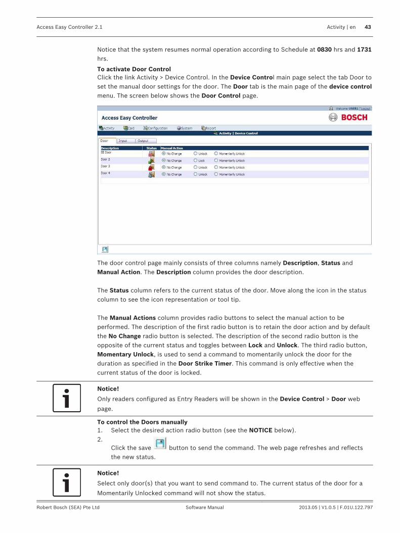
To activate Door ControlClick the link Activity > Device Control. In the Device Control main page select the tab Door toset the manual door settings for the door. The Door tab is the main page of the device controlmenu. The screen below shows the Door Control page.
The door control page mainly consists of three columns namely Description, Status andManual Action. The Description column provides the door description. The Status column refers to the current status of the door. Move along the icon in the statuscolumn to see the icon representation or tool tip. The Manual Actions column provides radio buttons to select the manual action to beperformed. The description of the first radio button is to retain the door action and by defaultthe No Change radio button is selected. The description of the second radio button is theopposite of the current status and toggles between Lock and Unlock. The third radio button,Momentary Unlock, is used to send a command to momentarily unlock the door for theduration as specified in the Door Strike Timer. This command is only effective when thecurrent status of the door is locked.
Notice!
Only readers configured as Entry Readers will be shown in the Device Control > Door web
page.
To control the Doors manually1. Select the desired action radio button (see the NOTICE below).2.
Click the save button to send the command. The web page refreshes and reflectsthe new status.
Notice!
Select only door(s) that you want to send command to. The current status of the door for a
Momentarily Unlocked command will not show the status.
Access Easy Controller 2.1 Activity | en 43
Robert Bosch (SEA) Pte Ltd Software Manual 2013.05 | V1.0.5 | F.01U.122.797

Input ControlThe Input Control menu allows you to check the status of all the Input Points and sends acommand to Arm/Disarm the device manually. This is a manually operated control and haspriority over the system set control. However, the system will resume normal operation once itencounters a valid schedule interval. For configuration of system control, refer to Input State, page 127. Let's explain this with an exampleThe door is scheduled as follows Unlock Door Start - 0830 hrs and End - 1730 hrs.The manual control is set as followsDisarm device 0730 hrs and Arm Device at 0800 hrsArm Device at 1230 hrs and Disarm device at 1315 hrs The figure below shows the status of the door during the schedule time and when there is amanual door control
Alarm Zone
Armed
0830hrs 1731hrs
Alarm Zone Status
according to
Schedule
Manual Input
Control
command sent
Resultant
Alarm Zone
Status
1. Disarm Zone at 0730hrs
2. Arm Zone at 0800hrs
3. Arm Zone at 1230hrs
4. Disarm Zone at 1315hrs
0730hrs 0800hrs
0830hrs0000hrs
1230hrs 1315hrs
2359hrs1731hrs
Legend:
All Input Points within the Alarm Zone are Disarmed
Alarm Zone
Armed
Alarm Zone
Disarmed
All Input Points within the Alarm Zone are Armed
Notice the system resumes normal operation according to Schedule at 0830 hrs and 1731 hrs.
To activate Input ControlClick the link Activity > Device Control. In the Device Control main page select the Input tab toset the manual input point settings. The screen below shows the Input Device Control page.
7.2.2
44 en | Activity Access Easy Controller 2.1
2013.05 | V1.0.5 | F.01U.122.797 Software Manual Robert Bosch (SEA) Pte Ltd

The input control page allows you to view the current status of all assigned Input Points. The input control consists of mainly three columns namely Description, Status andManualAction. The Description column provides the door description. The Status column refers to the current status of the input point. Move along the icon in thestatus column to see the icon representation or tool tip. The horizontal strip provides the Alarm Zone to which the Input Points belong. In this case,Undefined Input Point 1 belongs to Alarm Zone 1 and Undefined Input Point 2 is anindependent input point. In the preceding example Undefined Inpoint 1 belongs to Alarm Zone 1. Select a zone fromthe input points dropdown to arm or disarm the input points in an alarm zone. The screenbelow shows an example of an input point set in an alarm zone.
Click the arm or disarm button to arm/disarm the input points set in the alarmzones. The Manual Actions column provides radio buttons to select the manual action to beperformed. The description of the first radio button is to retain the door alarm zone and bydefault the No Change radio button is selected. The description of the second radio button isthe opposite of the current status and toggles between Disarm now and Arm now.
To control the Input points1. Select the desired action radio button
Access Easy Controller 2.1 Activity | en 45
Robert Bosch (SEA) Pte Ltd Software Manual 2013.05 | V1.0.5 | F.01U.122.797

2.Click the save button to arm the Input Points. The web page will refresh to reflectthe new status.
Output ControlThe Output Control menu allows you to check the status of all the Output Points and sends acommand to turn on/off the output points manually. This is a manually operated control andhas priority over the system set control. However, the system will resume normal operationonce it encounters a valid schedule interval. Let's explain this with an example:The door is scheduled as follows Unlock Door Start - 0830 hrs and End - 1730 hrs.The manual control is as follows -On Output 0730hrs and Off Input at 0800hrsOff Input at 1230hrs and On Output at 1315hrs The figure below shows the status of the door during the schedule time and when there is amanual door control.
Output Off
0830hrs 1731hrs
Output Status according to
Schedule
Manual OutputControl
command sent
ResultantOutput Status
1. On Output at 0730hrs
2. Off Input at 0800hrs
3. Off Output at 1230hrs
4. On Output at 1315hrs
0730hrs 0800hrs
0830hrs0000hrs
1230hrs 1315hrs
2359hrs1731hrs
Legend:
Output Points On
Output Points Off
Output OffOutput On
Notice the system resumes normal operation according to Schedule at 0830 hrs and 1731 hrs.
To activate Output ControlClick the link Activity > Device Control. In the Device control main page click the Output tab toset the manual output settings. The screen below shows the Output Device Control page.
7.2.3
46 en | Activity Access Easy Controller 2.1
2013.05 | V1.0.5 | F.01U.122.797 Software Manual Robert Bosch (SEA) Pte Ltd
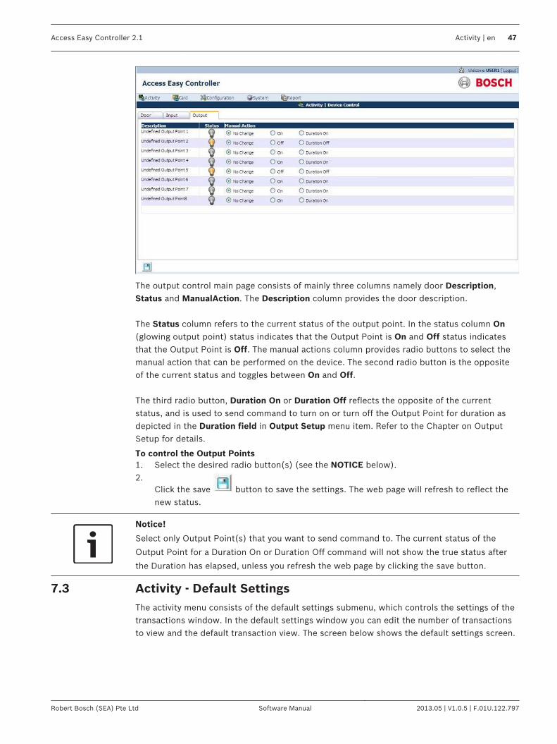
The output control main page consists of mainly three columns namely door Description,Status and ManualAction. The Description column provides the door description. The Status column refers to the current status of the output point. In the status column On(glowing output point) status indicates that the Output Point is On and Off status indicatesthat the Output Point is Off. The manual actions column provides radio buttons to select themanual action that can be performed on the device. The second radio button is the oppositeof the current status and toggles between On and Off. The third radio button, Duration On or Duration Off reflects the opposite of the currentstatus, and is used to send command to turn on or turn off the Output Point for duration asdepicted in the Duration field in Output Setup menu item. Refer to the Chapter on OutputSetup for details.
To control the Output Points1. Select the desired radio button(s) (see the NOTICE below).2.
Click the save button to save the settings. The web page will refresh to reflect thenew status.
Notice!
Select only Output Point(s) that you want to send command to. The current status of the
Output Point for a Duration On or Duration Off command will not show the true status after
the Duration has elapsed, unless you refresh the web page by clicking the save button.
Activity - Default SettingsThe activity menu consists of the default settings submenu, which controls the settings of thetransactions window. In the default settings window you can edit the number of transactionsto view and the default transaction view. The screen below shows the default settings screen.
7.3
Access Easy Controller 2.1 Activity | en 47
Robert Bosch (SEA) Pte Ltd Software Manual 2013.05 | V1.0.5 | F.01U.122.797
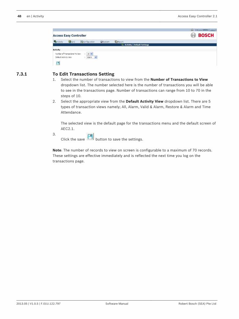
To Edit Transactions Setting1. Select the number of transactions to view from the Number of Transactions to View
dropdown list. The number selected here is the number of transactions you will be ableto see in the transactions page. Number of transactions can range from 10 to 70 in thesteps of 10.
2. Select the appropriate view from the Default Activity View dropdown list. There are 5types of transaction views namely; All, Alarm, Valid & Alarm, Restore & Alarm and TimeAttendance.
The selected view is the default page for the transactions menu and the default screen ofAEC2.1.
3.Click the save button to save the settings.
Note: The number of records to view on screen is configurable to a maximum of 70 records.These settings are effective immediately and is reflected the next time you log on thetransactions page.
7.3.1
48 en | Activity Access Easy Controller 2.1
2013.05 | V1.0.5 | F.01U.122.797 Software Manual Robert Bosch (SEA) Pte Ltd
Card AdministrationCard administration refers to the parameters that control the access rights of the cards. Cardparameters contain information such as which card reader a cardholder can access at aspecified schedule. The card parameters are used to configure additional card information likeDepartment, Arm/disarm, Access Group …etc. This chapter describes the features of the Card parameter function and the card assignment,enrollment, adding batch cards and database import/export procedure.
Notice!
AEC2.1 supports a maximum capacity of 20,480 cardholders.
Notice!
As the AEC2.1 supports different types of Card Formats, such as BOSCH 37-Bits, 26-Bits, 34-
bits or other customized format, there will be an overlapping of card number range. There is a
possibility to assign the same Card Number(s) with different Facility Code. The AEC2.1
processes the card number along with the Facility code.
The cards main menu consists of the following submenus:-– Card Administration– Access Groups– Card Format– Department– Reset APB– Default setting The above submenus are explained in detail in the following pages. Card Administration refers to the access rights of the cards and the cardholder. Cardadministration consists of the following card functionality parameters– Assignment– Enrollment– Import/Export– Batch Card The above card parameters are explained in detail in the following pages.
Card AssignmentCard Assignment refers to adding or editing card details. The card assignment parameter alsorefers to the access rights of the card and the schedule when a card can be accessed by thecard reader. Card assignment menu consists of the following card parameters: - Card Details– Card Number– User Name– Facility Code
8
8.1
Access Easy Controller 2.1 Card Administration | en 49
Robert Bosch (SEA) Pte Ltd Software Manual 2013.05 | V1.0.5 | F.01U.122.797
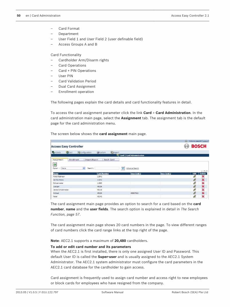
– Card Format– Department– User Field 1 and User Field 2 (user definable field)– Access Groups A and B Card Functionality– Cardholder Arm/Disarm rights– Card Operations– Card + PIN Operations– User PIN– Card Validation Period– Dual Card Assignment– Enrollment operation The following pages explain the card details and card functionality features in detail. To access the card assignment parameter click the link Card > Card Administration. In thecard administration main page, select the Assignment tab. The assignment tab is the defaultpage for the card administration menu. The screen below shows the card assignment main page.
The card assignment main page provides an option to search for a card based on the cardnumber, name and the user fields. The search option is explained in detail in The SearchFunction, page 57. The card assignment main page shows 20 card numbers in the page. To view different rangesof card numbers click the card range links at the top right of the page. Note: AEC2.1 supports a maximum of 20,480 cardholders.
To add or edit card number and its parametersWhen the AEC2.1 is first installed, there is only one assigned User ID and Password. Thisdefault User ID is called the Super-user and is usually assigned to the AEC2.1 SystemAdministrator. The AEC2.1 system administrator must configure the card parameters in theAEC2.1 card database for the cardholder to gain access. Card assignment is frequently used to assign card number and access right to new employeesor block cards for employees who have resigned from the company.
50 en | Card Administration Access Easy Controller 2.1
2013.05 | V1.0.5 | F.01U.122.797 Software Manual Robert Bosch (SEA) Pte Ltd

Card DetailsCard details refer to the card number, user name, department and the profile of thecardholder. Follow the steps below to add a new card and to assign access rights to thecardholder. 1.
Click the add button in the card assignment main page to add a new card. TheCardAssignment > Add main page shows the card number and user name text boxes.
2. Enter a card number in the Card Number field.3. Enter the Cardholder's (User) Name in the User Name field.4. The CardAssignment > Add main page consists of two card parameters or tabs namely
Details and Functionality. Click the Details tab and the screen below appears.
5. Enter the facility code in the Facility code field. The Facility code is configured in theCard > DefaultSettings page. Refer to Card - Default Settings, page 73 for moreinformation.
6. Select the Card Format from the card format dropdown list. The card format isconfigured in the Card > CardFormat page. Refer to Card Format, page 68 for moreinformation.
Notice!
The Card Number together with the Card Format and Facility Code is a unique field, so do not
enter duplicate information. The card number and the facility code are mandatory fields.
7. Select the Department from the department dropdown list. The department is configuredin the Card > Department page. Refer to Department, page 71 for more information.
8. Enter the required details in User Field 1 and User Field 2.
Notice!
The User Field 1 and User Field 2 are configured in Card > Default Settings page. Refer Card -
Default Settings, page 73 for more information.
8.1.1
Access Easy Controller 2.1 Card Administration | en 51
Robert Bosch (SEA) Pte Ltd Software Manual 2013.05 | V1.0.5 | F.01U.122.797

9. Select the Access Grouping for the cardholder in Access Group A and/or Access Group Bfrom the dropdown list. Leave the entry blank if there is only one or no assignment. Theaccess group is configured in Card > Access Group page. Refer to Access Groups, page67 for more information.
Notice!
Setting the access group allows the cardholder to access the door as scheduled in the access
group settings.
10. The cardholder photo uploaded here is used for the video verification feature. If thisphoto matches with the cardholder's video from the identification camera at the accessdoor, then the door operator grants or denies door access according to the cardholder'saccess rights. Click the browse button to upload the cardholder photo. A browse windowpops up as shown below.
a. Select a file and click the upload button. The following error message will pop upif the file size is more than 5 KB.
b. Click the OK button and browse another file with a smaller file size.
52 en | Card Administration Access Easy Controller 2.1
2013.05 | V1.0.5 | F.01U.122.797 Software Manual Robert Bosch (SEA) Pte Ltd

Notice!
AEC2.1 supports image files with format JPEG and BMP
11. Upload the photo and a preview can be seen in the Photo preview window as shownbelow.
Notice!
The photo is necessary for the video verification feature. Refer to Video Verification, page 31
for more details.
12.Click the save button to save the settings. Click the back button if you want tocancel the settings and return to the card assignment main page.
Card FunctionalityCard Functionality refers to the access rights and functionality of the cards such as Arm/Disarm the door, access behavior and validation dates. Each card can be configured withdifferent access rights. Some of the settings of the card can be activated in co-ordination withthe card reader parameters such as Card + PIN mode. These settings can be modified at anypoint of time. The screen below shows the card functionality page.
8.1.2
Access Easy Controller 2.1 Card Administration | en 53
Robert Bosch (SEA) Pte Ltd Software Manual 2013.05 | V1.0.5 | F.01U.122.797

All the card functions are explained in detail below
Cardholder is able to Arm/DisarmIf this feature is checked, it implies that the cardholder is given the authority to arm/disarm aspecific Alarm Zone or All Alarm Zones as defined in the field. Select the alarm zone from theZone dropdown list. This functionality works in conjunction with the reader that is set to arm/disarm the alarmzone. Refer to Door Output Settings (for Entry Reader, Entry and Arm/Disarm Reader), page 80for more details. If this function is enabled on the cardholder, then the alarm zone will toggle from arm todisarm or vice versa when the cardholder presses 0 before presenting the card to the cardreader. However if the cardholder presents the card to the reader without activating the arm/disarm function on the reader keypad, it will unlock the door and disarm the alarm zonedepending on the cardholders access right.
Cardholder must abide by holiday schedules (to work in conjunction with Reader Options)If this feature is checked, it implies the cardholders' access rights are different duringholidays. It works in conjunction with the Reader Options on holidays followed by the holidayschedules. If checked, the 4 sets of Regular or Special Holiday schedules are used to operatethe access mode, e.g. Cardholder is allowed to access the controlled area during weekdaysand during office hours. However during holidays, the cardholder is allowed to access thisarea as defined by the Holiday schedule intervals.
Allow exit reader usage only in accordance with time schedulesThis mode is valid only if there is an exit reader. If this function is checked, the Reader willallow the cardholder to exit the area within the valid Schedule intervals. When the function isunchecked, the reader will allow the cardholder to exit the area at all times.
Card holder can enable enrollment operationIf this feature is checked, it implies the selected cardholders have the right to use their card toactivate a Reader to be in enrollment mode. Refer to Card Enrollment using Pre-assignedEnrollment Card, page 61 for more details.
54 en | Card Administration Access Easy Controller 2.1
2013.05 | V1.0.5 | F.01U.122.797 Software Manual Robert Bosch (SEA) Pte Ltd

Disable card from all access permanentlyIf this feature is checked, it implies the cardholder will be denied access from the systemimmediately. This feature is useful to prevent illegal access to the system if the cardholderloses or misplaces the card.
Card holder with one time access onlyIf this feature is checked, it implies the cardholder will have only one time access to thesystem. This means that after the card holder has gained access, the cardholder's access willbecome invalid immediately. To gain access again, the AEC2.1 system administrator has toreactivate the one time access right. This function is useful in a remote station deliveryapplication. Ensure the Valid radio button is selected for the Access Status. After the card has been usedfor one time access, the Access Status will expire immediately and the Access Status will beupdated to Expired automatically.
Card + PIN is required on Keypad readersThis mode works only when the Card Reader's PIN mode is set. If this feature is checked, itimplies the cardholder must enter the PIN after presenting the card to the reader to gainaccess. The cardholder can configure up to 7 digits for the PIN. When using it on the reader, the cardholder must enter the PIN followed by the ‘E’ key for C3readers and S-Series reader or ‘#’ for HID compliant readers. For example, if the cardholderconfigures less than 7 digits as the pin, for example ‘5566’, then the cardholder must enter‘5566#’ for the PIN.
Enter user PIN (1-7 digits)This field is to be used for the Card + PIN mode (default PIN code 1234000).
Extended duration for door accessThis function is to facilitate special card holders to have extended duration for Door Strike andKeypad Time-out. If this feature is checked, it allows the cardholder to keep the door open fora longer time after a successful access is granted before a Door Held Open alarm is activated.The Keypad Time-out duration is also extended by the selected time on top of the normalKeypad Time-out duration. An example of such an application is for the handicapped peoplewho need a longer time to access the door. To select the extended time duration, select the time in seconds from the dropdown listbeside the extended duration for door access. The range is from 0 to 255 seconds.
Card Validation DatesThis feature defines the start and end date parameters. The Start Date is the date from when the card is valid and End Date is the date from when thecard is no longer valid. The card will not be able to access any door before the Start Date andafter the End Date. Cards having such parameter settings are normally issued to contractors or temporary staffwho will only be allowed to access the controlled area for a known period of time. The usageof this feature can be either one or the combination of both. You can define a card that onlyallow access after a specified future date but doesn't have an expiry date. In this case, youonly select and set the Start Date but leave the End Date unchecked.Alternatively, you can define a card that is valid with immediate effect but is valid only for 2days; in this case you can leave the Start Date unchecked but check and select the End Date.
Access Easy Controller 2.1 Card Administration | en 55
Robert Bosch (SEA) Pte Ltd Software Manual 2013.05 | V1.0.5 | F.01U.122.797

Notice!
You must check the respective box for Start Date or End Date in order for it to be effective.
Dual Card AssignmentThis mode is useful if 2 cards are required to be presented in sequence to the Reader tounlock the door. This mode works in conjunction with the Dual Card Configuration. Refer toDual Card Configuration, page 87 for more information. The First Card has to be presentedfirst before the Second Card is presented, else the door will not unlock. A Don't Care Cardcan act as the first or second card. In this setup here, you will need to define whether a cardis a First Card, Second Card or Don't Care Card, and which group it belongs to. Cards fromdifferent groups cannot unlock the door. Select the radio button besides Dual Card presentation sequence to enable this mode. Youwill need to define whether a card is a First Card, Second Card or Don't Care Card from thedropdown list. You will also have to select the Dual Card Group ID from the dropdown list. 2cards from the same Dual Card Group ID must be presented to the Reader to unlock the door.The table below shows all the possible card combinations that can be presented to theReader.
Possible card combination
First card Second Card
Don't Care Don't Care
First Card Don't Care
Don't Care Second Card
First Card Second Card
To select Card Functionality1. Select the Card Functionality tab and click the corresponding check boxes to show a tick
mark. To de-select the function click the checkbox again.2. To assign the Alarm Zone, select the appropriate Alarm Zone from the Zone dropdown
list.3. Click the appropriate radio button to show if the card is a valid card or an expired card.4. To edit User PIN code, highlight the default PIN code and enter the new User PIN code.
Notice!
You can enter 1 to 7 digits for the User PIN code. For security reason, every character entered
for the PIN code is represented by an dot.
To select and edit Card Validation Period1. To enable the Start Date, click the Start Date check box to show a tick mark. To deselect,
click the checkbox again.2. Select the appropriate Day from the calendar picker.3. To enable the End Date, click on the End Date check box to show a tick mark. To de-
select, click the checkbox again.
56 en | Card Administration Access Easy Controller 2.1
2013.05 | V1.0.5 | F.01U.122.797 Software Manual Robert Bosch (SEA) Pte Ltd
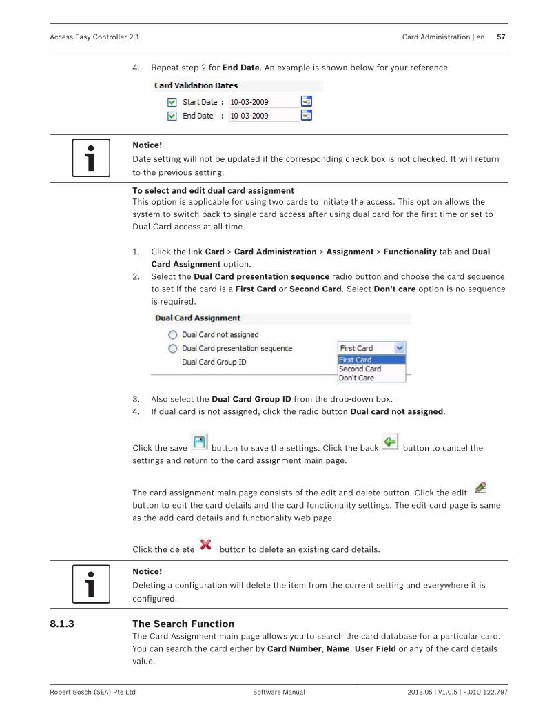
4. Repeat step 2 for End Date. An example is shown below for your reference.
Notice!
Date setting will not be updated if the corresponding check box is not checked. It will return
to the previous setting.
To select and edit dual card assignmentThis option is applicable for using two cards to initiate the access. This option allows thesystem to switch back to single card access after using dual card for the first time or set toDual Card access at all time. 1. Click the link Card > Card Administration > Assignment > Functionality tab and Dual
Card Assignment option.2. Select the Dual Card presentation sequence radio button and choose the card sequence
to set if the card is a First Card or Second Card. Select Don't care option is no sequenceis required.
3. Also select the Dual Card Group ID from the drop-down box.4. If dual card is not assigned, click the radio button Dual card not assigned.
Click the save button to save the settings. Click the back button to cancel thesettings and return to the card assignment main page.
The card assignment main page consists of the edit and delete button. Click the edit button to edit the card details and the card functionality settings. The edit card page is sameas the add card details and functionality web page.
Click the delete button to delete an existing card details.
Notice!
Deleting a configuration will delete the item from the current setting and everywhere it is
configured.
The Search FunctionThe Card Assignment main page allows you to search the card database for a particular card.You can search the card either by Card Number, Name, User Field or any of the card detailsvalue.
8.1.3
Access Easy Controller 2.1 Card Administration | en 57
Robert Bosch (SEA) Pte Ltd Software Manual 2013.05 | V1.0.5 | F.01U.122.797

To find a particular Cardholder based on Name.1. If you wish to find a Card Number whose Name is known, select the option Name from
the Option drop down box.
2. Enter the first few characters of the person's name in the Search field and click thesearch button. If you know the full name of the cardholder enter the full name in thesearch field.During the Search function, one of the following cases can happen:a. If the name specified is not found in the card database, the No records found messageappears, orb. If the result has only one match, the Card assignment page with the cardholders namewill appear, orc. If the result yields more than one match, a window will appear below the function fieldfor further selection.We will elaborate on case c. For example, let’s search the database for Cardholder withthe name “Maria”.a. Enter the word Maria in the Search field.b. Click the search button and the following result will be displayed.
The database contains two Cardholders whose name satisfies the word “Maria”.c. Click the edit button along the desired name to view and edit the cardholder details.
To find a particular Cardholder based on Card Number.If you want to find a Cardholder's details whose Card Number is known, use the Searchfunction as shown below. 1. Select the Card Number option from the Option dropdown list.
2. Enter the exact Card Number in the Search field.3. Click the search button.4. The card assignment main page appears with the list of card numbers entered.
Notice!
If the card number specified is not configured in the card database, than No records found
message appears.
To find a particular Cardholder based on User Field 1 or User Field 2.1. If you wish to find a Card Number whose user field 1 or user filed 2 is known, select the
option User Field 1 or User Field 2 from the Option drop down box.
2. Enter the value in search field.3. Click the search button.
58 en | Card Administration Access Easy Controller 2.1
2013.05 | V1.0.5 | F.01U.122.797 Software Manual Robert Bosch (SEA) Pte Ltd

4. The card assignment main page appears with the list of card numbers entered.
Advance SearchThe advance search window allows you to search the card database more easily. The AdvanceSearch window is shown below.
Enter a value in any one field of the search window. You can search the card database on thefollowing parameters Card Number, Name, Card Format, Facility Code, User Field 1, UserField 2, Department, Access Group A, Access Group B, Start date or End date. After enteringthe value click the search button. The search result is displayed in the card assignment mainpage.
Click the back button if you do not want to continue with the search option.
Card EnrollmentThe card enrollment option allows the use of any unknown proprietary wiegand card format,where an administrator can activate a Reader, either by pre-assigned enrollment card or byweb page, to be in enrollment mode and enroll any card into the card database (maximum bitlength is 64). The sections below will guide you on how to activate a Reader to be inenrollment mode, both by enrollment card feature and by web page feature.
Card Enrollment using Web PageFollow the steps below if you wish to enroll a card of unknown proprietary wiegand cardformat using the web page.
8.2
8.2.1
Access Easy Controller 2.1 Card Administration | en 59
Robert Bosch (SEA) Pte Ltd Software Manual 2013.05 | V1.0.5 | F.01U.122.797

1. Select the link Card > Card Administration menu. In the card administration main pageselect the Enrollment tab and the screen below appears.
Select a door from the Cards Enrollment Reader dropdown list. This reader can be adedicated reader or a door access reader. However, if a door access reader is selected asan Enrollment reader, the reader will only function as an enrollment reader and the dooraccess functions will be temporary disabled until the reader is set back as a door accessreader.
2. Select a Reader from the Cards Enrollment Reader dropdown to be the enrollmentReader. In this example, we select Door 1 to be the enrollment Reader.
3.Click the save button to activate the selected Reader as the enrollment Reader.
4. Present the card with unknown Wiegand Format to the enrollment Reader. The card thathas been presented to the enrollment Reader will appear in the box List of scannedcards.
5. You can now assign any Card Number and Name to the card.
Notice!
It is recommended that you assign a number to the card of unknown wiegand format
beforehand and stick a label on the card, so that it is easier to refer to the card number
during the card enrollment process.
60 en | Card Administration Access Easy Controller 2.1
2013.05 | V1.0.5 | F.01U.122.797 Software Manual Robert Bosch (SEA) Pte Ltd

6. Highlight the card in the List of scanned cards that you are assigning the Card Numberand Name to and enter the card number and name in the appropriate field as shownbelow.
7.Click the save button to save the card details.
Notice!
If you are using a door access reader as a temporary enrollment reader, after enrolling the
unknown wiegand card, it is required to reset the reader back to a door access reader.
Card Enrollment using Pre-assigned Enrollment CardCardholders can use their cards to activate a reader in enrollment mode if such functionality isassigned to the cards. This functionality is assigned by enabling the Card holder can enableenrollment operation check box. Refer to Card Functionality, page 53 for more details. Follow the steps below if you wish to use the pre-assigned enrollment card to enroll a card ofunknown proprietary Wiegand format. 1. Find the reader that you wish to use for enrollment.2. Press the ‘7’ key on the reader keypad.3. Flash the pre-assigned enrollment card to enable the reader in enrollment mode. The
reader will remain in enrollment mode until the keypad time out period has passed(default is 10 seconds).
4. Present cards with unknown Wiegand format to the enrollment reader during this periodto enroll them in the system.
5. The enrollment reader reverts back to normal state/operation after the keypad time outperiod has passed.
6. Refer Card Assignment, page 49 to configure the information of the enrolled cardsaccordingly.
Import/Export FunctionThis feature allows you to export or import the card database in a familiar CSV format. The import/Export function is also used as a backup and restores utility. Select the link Card >Card Administration and in the card administration page select the tab Import/Export, thescreen below appears.
8.2.2
8.3
Access Easy Controller 2.1 Card Administration | en 61
Robert Bosch (SEA) Pte Ltd Software Manual 2013.05 | V1.0.5 | F.01U.122.797

Exporting the Card DatabaseFollow the steps below to export the card database.1.
To export the card database, click the export button. A screen as shown below willappear.
8.3.1
62 en | Card Administration Access Easy Controller 2.1
2013.05 | V1.0.5 | F.01U.122.797 Software Manual Robert Bosch (SEA) Pte Ltd

2. Save the file to a local hard disk or an external drive. Click the Save button and thescreen below appears.
3. Select the drive you want to save the file in and give an appropriate File Name. Click thesave button to save the file.
4. Once the download is complete the screen below appears.
5. Click Open to view the file else click the Close button to close the window.
Importing the Card DatabaseFollow the steps below to import the above edited CSV file. 1. To import the card database, select a .CSV file using the Browse button or enter the
directory and the file name directly in the space provided beside Select a CSV file.
8.3.2
Access Easy Controller 2.1 Card Administration | en 63
Robert Bosch (SEA) Pte Ltd Software Manual 2013.05 | V1.0.5 | F.01U.122.797

2. Select the checkbox besides Clear the current database and then import the cards ifyou want to delete the existing database and import the new database.
3.Click the Import button to import the database to the system.
Batch CardsBelow sections describe the adding and deleting processes for Batch Cards.
Adding Batch Cards1. Select the link Cards > Card Administration. From the card administration main page
select the Batch Card tab.
2. Enter the card number in the Card Number field (the number specified here will be thestarting number of the batch card operation and will be included).
3. The number in the Facility code is configured in Card > Default Settings, if the code isdifferent from the default, then change the facility code. Refer to Card - Default Settings,page 73 for more details. Enter 0 if the Card Format doesn't support Facility Code.
4. Select the appropriate Card Format from the dropdown list. The Card format isconfigured in the section Cards > Card Format menu. Refer to Card Format, page 68 formore details.
5. Enter the number(s) of card number to add in the Number of Cards field.6.
Click the add button. If there is no error during the card numbers addition, theCards added successfully message will be shown. Refer to System Messages, page 65 ifother message are displayed.
7.Click the save button to return to the menu item first page.
8. Proceed to edit the newly added card number parameters.
To Delete a Batch of Card NumberThe procedures to delete a range of card numbers is similar to adding a batch of card
numbers. Instead of clicking the add button, click the delete button.
!Warning!
This function must be used carefully as it is not reversible. The delete option will delete all
the information permanently from the database.
8.4
8.4.1
8.4.2
64 en | Card Administration Access Easy Controller 2.1
2013.05 | V1.0.5 | F.01U.122.797 Software Manual Robert Bosch (SEA) Pte Ltd

To Add a Batch of Card Number with Same Data EntriesThis function allows addition of a range of card numbers with data entries copied from areference card number (see NOTICE below). All card number(s) added will be copied with thedata/parameters of the reference card. However, the following parameters will not be copied,Facility code, Card Format and Username as all these parameters relates to the individualcard and cardholder.
Notice!
In order for the process to be carried out, the reference card number entered must be exact
in term of Card Number, Facility Code and Card Format. The Controller will prompt the user
with an error message if a non-existence reference card number is specified.
This is very useful and time saving when assigning a batch of card number to a specifieddepartment staff.
Notice!
The Card Number 18020 is of BOSCH-ADC Proprietary Card Format with Facility Code of 0. It
is used as a reference as we wanted to set similar parameters for the new card numbers such
as Access Group(s), …etc.
1. In the batch card main page enter all the details as described in Add batch card section.In the default parameter window enter the card number in the card number field fromwhich you want to copy the card parameters.
2.Click the add button to proceed. A message will appear. Refer to System Messages,page 65 to interpret the meaning of the message.
Using automatically replace the existing card(s) with default/reference card informationfunction This function will overwrite all data within a card number when the software encountersexisting card number (with same Card Format and Facility Code) during Batch Cardsfunction. It allows recycling of card number allocation when employee resigns. The function will be activated when a tick appears in the check box.
!Warning!
This function should be used carefully as it is not reversible. All information on the existing
card number in the database will be permanently overwritten once this option is carried out.
System MessagesThe following are the sample messages that are displayed when batch card function is carriedout. Card numbers already exist.This message indicates that the card number, having the same Facility code and Card Format,already exist in the database and the Overwrite function was not activated. Card database full. 3 cards starting from card number 20479 were not added.
8.4.3
8.4.4
Access Easy Controller 2.1 Card Administration | en 65
Robert Bosch (SEA) Pte Ltd Software Manual 2013.05 | V1.0.5 | F.01U.122.797

This message appears when an attempt is made to add in more Card number when the carddatabase is already full. It indicates the card number and number of card(s) not added, in thisexample; card number 20480, 20481, and 20482 was not added. Card not found.This message indicates that the Card number specified during a batch card deletion does notexist and the deletion could not proceed. Cards deleted successfully.This message indicates that all Card Numbers specified during a batch card deletion has beencarried out successfully. 5 cards deleted.This message indicates that only 5 Card Numbers out of the Number of Cards specified duringa batch card deletion was carried out successfully. The remaining card numbers doesn't existin the database. 3 cards added successfully.This message indicates that only 3 Card Numbers out of the Number of Cards specified duringa batch card addition was added successfully. The remaining card numbers already exist in thedatabase and the Overwrite function was not activated. Unable to perform add operation.This message appears when the Card Number or the Number of Card field was not specifiedduring the add operation. Unable to perform delete operation.This message appears when the Card Number or the Number of Card field was not specifiedduring the delete operation. Reference card not found.This message shows that the reference card number does not exist.
66 en | Card Administration Access Easy Controller 2.1
2013.05 | V1.0.5 | F.01U.122.797 Software Manual Robert Bosch (SEA) Pte Ltd

Card Fields ConfigurationThis chapter explains the configuration of the card information fields.
Access GroupsAn Access Group defines a list of readers that the cardholders can access within certainauthorized time periods (pre-defined Schedule). This means that only within this Schedule,cardholders in this access group can access this reader. AEC2.1 supports upto 254programmable Access Groups. In addition, there are two more unique access groups. They are the Full Access group thatallows cardholders to access all readers at all times, usually reserved for the President,Chairman or Directors of the company and the Unused group that prohibits cardholder toaccess any reader at all times. All these features are explained in this chapter and this chaptercovers a step by step guide to set up the Access Groups. Access Group is implemented to simplify the process of assigning cardholder's access rightsto each reader. Usually a group of cardholders can access the same group of readers, using acommon Schedule. Assigning access groups reduces the pain of going through the same stepsrepeatedly. Rather than assigning each reader to one of the cardholder and going through thesame steps repeatedly, grouping of Access Group is implemented. It is highly recommendedthat detail planning be done before setting up the Access Groups. Each Access Group canconfigure up to 32 readers with each reader linked to a Schedule. Click the link Card > Access group to access the access group page. The screen below showsthe Access Group main page.
Click the corresponding range link at the top right to view the access groups.
To Configure/Edit Access Group Parameters1.
Click the add button to add a new access group. The screen below appears.
9
9.1
9.1.1
Access Easy Controller 2.1 Card Fields Configuration | en 67
Robert Bosch (SEA) Pte Ltd Software Manual 2013.05 | V1.0.5 | F.01U.122.797

Notice!
The Reader's Description shown above is configured in Card Readers setting. Refer to Door
Settings (Card Reader Settings), page 74 for more information.
2. Enter a description for the access group in the Description field.3. Select the appropriate check boxes besides the door description to be assigned to this
Access Group.4. Select the appropriate Schedule, from the dropdown list, for each selected Reader. Refer
to Schedules, page 136 for more information about schedule configuration.5. For an Elevator Reader, you need to select the Floor List and assign appropriate Floor
level that you want to allocate to this access group.
Notice!
You need to assign a Reader as an Elevator Reader in Card Reader Setup and assign Floor
Relay in the Floor Output Settings before assigning any access group for elevator reader.
Refer to Door Settings (Card Reader Settings), page 74 for more information.
6. To confirm the Floor List, click the OK button.7.
Click the save button to save the settings.
Card FormatThe card format feature allows you to customize the AEC2.1 to accept up to 16 different typesof Wiegand Card Format. AEC2.1 supports up to a maximum of 64 bit card format and up to 8Parity Format.
To activate Card Format 1. Click the link Card > Card Format to access the card format page. The screen below
shows the Card format main page.
9.2
68 en | Card Fields Configuration Access Easy Controller 2.1
2013.05 | V1.0.5 | F.01U.122.797 Software Manual Robert Bosch (SEA) Pte Ltd

2.Click the add button to add a new card format. The screen below shows the addCard format main page.
3. Enter a Description for this Card Format in the Description field.4. Enter the format for the Card Encoded Format field accordingly.5. Repeat for Parity Format 1 (see NOTICE).6. Repeat for Parity Format 2 (Apply the condition in NOTICE here and for subsequent
Parity Format fields).
Notice!
The entries to this field must not contain Parity Bit Location that depends on the resultant
Parity Bit of the next or higher (Parity Format 2 to 8) Parity Format field entries.
If the Card Format doesn't support Parity checking, leave the All Parity Format fields blank. In order to understand how to configure the different format, the standard 26-Bit WiegandCard Format will be used as an example. Example: 26-Bit Wiegand Card FormatThe 26-bits of transmission from the reader to the AEC2.1 consist of two parity bits and 24code bits. The first transmitted bit is the even parity bit E, it is calculated over the first 12 bits.The last bit transmitted is the Odd parity O, it is calculated over the last 12 bits. The string of bits for this code format is shown in the following tables. Due to the lack ofspace, the 26-Bits are split into two separate rows of 13 each. Code Format
1 2 3 4 5 6 7 8 9 10 11 12 13
E F F F F F F F F C C C C
14 15 16 17 18 19 20 21 22 23 24 25 26
C C C C C C C C C C C C O
Access Easy Controller 2.1 Card Fields Configuration | en 69
Robert Bosch (SEA) Pte Ltd Software Manual 2013.05 | V1.0.5 | F.01U.122.797

Legend:E: Resultant Even Parity BitF: Facility Code BitC: Card Number BitO: Resultant Odd Parity Bit Parity Format
1 2 3 4 5 6 7 8 9 10 11 12 13
P E E E E E E E E E E E E
14 15 16 17 18 19 20 21 22 23 24 25 26
O O O O O O O O O O O O P
Legend:E: Even Parity Bit LocationP: Resultant Even and Odd Parity BitO: Odd Parity Bit Location In order for the AEC2.1 to decode the data string correctly, we need to configure the codeaccordingly. Referring to the Code Format TableFor Card Encoded Format1. Enter P or p for the resultant Even (E) and Odd (O) Parity Bit2. Enter F or f for the Facility Code Bit (F)3. Enter C or c for the Card Number Bit (C) Referring to the Parity Format TableFor the Odd Parity Format (Parity Format 1).1. Enter O or o for the resultant Odd Parity Bit (O)2. Enter X or x for Odd Parity Bit Location.3. Enter B or b otherwise. For the Even Parity Format (Parity Format 2).1. Enter E or e for the resultant Even Parity Bit (E)2. Enter X or x for Even Parity Bit Location.3. Enter B or b otherwise. With the information, proceed to configure the Card Format as shown below.
70 en | Card Fields Configuration Access Easy Controller 2.1
2013.05 | V1.0.5 | F.01U.122.797 Software Manual Robert Bosch (SEA) Pte Ltd

Notice!
The system will not allow you to delete a card format if the card format is already in use.
Department1. Click the link Card > Department to edit or add a new department. The screen below
shows the department page.
2.Enter the department description in the Description field and click the add buttonto add a new department.
3. The added department appears in the department main page table.
9.3
Access Easy Controller 2.1 Card Fields Configuration | en 71
Robert Bosch (SEA) Pte Ltd Software Manual 2013.05 | V1.0.5 | F.01U.122.797
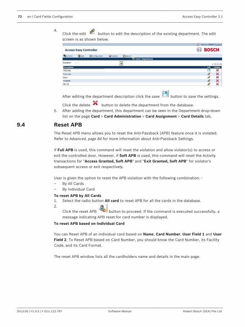
4.Click the edit button to edit the description of the existing department. The editscreen is as shown below.
After editing the department description click the save button to save the settings.
Click the delete button to delete the department from the database.5. After adding the department, this department can be seen in the Department drop-down
list on the page Card > Card Administration > Card Assignment > Card Details tab.
Reset APBThe Reset APB menu allows you to reset the Anti-Passback (APB) feature once it is violated.Refer to Advanced, page 84 for more information about Anti-Passback Settings. If Full APB is used, this command will reset the violation and allow violator(s) to access orexit the controlled door. However, if Soft APB is used, this command will reset the Activitytransactions for "Access Granted, Soft APB" and "Exit Granted, Soft APB" for violator'ssubsequent access or exit respectively. User is given the option to reset the APB violation with the following combination: -– By All Cards– By Individual Card
To reset APB by All Cards1. Select the radio button All card to reset APB for all the cards in the database.2.
Click the reset APB button to proceed. If the command is executed successfully, amessage indicating APB reset for card number is displayed.
To reset APB based on Individual Card You can Reset APB of an individual card based on Name, Card Number, User Field 1 and UserField 2. To Reset APB based on Card Number, you should know the Card Number, its FacilityCode, and its Card Format. The reset APB window lists all the cardholders name and details in the main page.
9.4
72 en | Card Fields Configuration Access Easy Controller 2.1
2013.05 | V1.0.5 | F.01U.122.797 Software Manual Robert Bosch (SEA) Pte Ltd

1. Click the radio button Individual Card to reset APB for a particular card as shown below.
2. Enter the Name, Card Number, User Field 1 or User Field 2 of the APB violator in theSearch field.
3. The Reset APB main page displays the result of the search criteria.4. You can also select the cardholder name from the existing list and click the reset APB
button to Reset the APB settings.
Card - Default SettingsThis setting allows you to define the descriptive Name for the two user fields and the globalFacility Code that appear under the title Card Details in Card Assignment page. These userfields are limited to 20 character entries each while the Facility code range depends on theCard Format in use.
To Edit the User Definable Fields and Facility Code1. In the User Definable Fields window enter the Description for User Field 1in the User
Field 1 field.
2. Repeat for User Field 2.3. In the facility code window enter the default Facility Code (you can obtain this code from
your card supplier; enter "0" if the Card Format doesn't support Facility Code).4.
Click the save button to save the settings.The changes done here are updated in the Card > Card Details > Assignment page.
9.5
9.5.1
Access Easy Controller 2.1 Card Fields Configuration | en 73
Robert Bosch (SEA) Pte Ltd Software Manual 2013.05 | V1.0.5 | F.01U.122.797
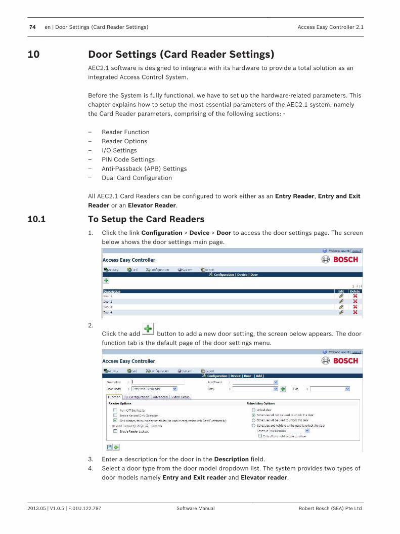
Door Settings (Card Reader Settings)AEC2.1 software is designed to integrate with its hardware to provide a total solution as anintegrated Access Control System. Before the System is fully functional, we have to set up the hardware-related parameters. Thischapter explains how to setup the most essential parameters of the AEC2.1 system, namelythe Card Reader parameters, comprising of the following sections: - – Reader Function– Reader Options– I/O Settings– PIN Code Settings– Anti-Passback (APB) Settings– Dual Card Configuration All AEC2.1 Card Readers can be configured to work either as an Entry Reader, Entry and ExitReader or an Elevator Reader.
To Setup the Card Readers1. Click the link Configuration > Device > Door to access the door settings page. The screen
below shows the door settings main page.
2.Click the add button to add a new door setting, the screen below appears. The doorfunction tab is the default page of the door settings menu.
3. Enter a description for the door in the Description field.4. Select a door type from the door model dropdown list. The system provides two types of
door models namely Entry and Exit reader and Elevator reader.
10
10.1
74 en | Door Settings (Card Reader Settings) Access Easy Controller 2.1
2013.05 | V1.0.5 | F.01U.122.797 Software Manual Robert Bosch (SEA) Pte Ltd
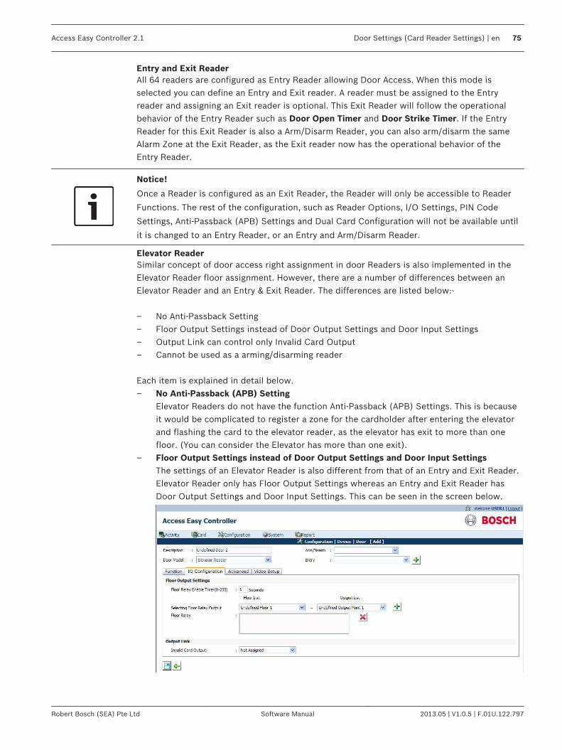
Entry and Exit ReaderAll 64 readers are configured as Entry Reader allowing Door Access. When this mode isselected you can define an Entry and Exit reader. A reader must be assigned to the Entryreader and assigning an Exit reader is optional. This Exit Reader will follow the operationalbehavior of the Entry Reader such as Door Open Timer and Door Strike Timer. If the EntryReader for this Exit Reader is also a Arm/Disarm Reader, you can also arm/disarm the sameAlarm Zone at the Exit Reader, as the Exit reader now has the operational behavior of theEntry Reader.
Notice!
Once a Reader is configured as an Exit Reader, the Reader will only be accessible to Reader
Functions. The rest of the configuration, such as Reader Options, I/O Settings, PIN Code
Settings, Anti-Passback (APB) Settings and Dual Card Configuration will not be available until
it is changed to an Entry Reader, or an Entry and Arm/Disarm Reader.
Elevator ReaderSimilar concept of door access right assignment in door Readers is also implemented in theElevator Reader floor assignment. However, there are a number of differences between anElevator Reader and an Entry & Exit Reader. The differences are listed below:- – No Anti-Passback Setting– Floor Output Settings instead of Door Output Settings and Door Input Settings– Output Link can control only Invalid Card Output– Cannot be used as a arming/disarming reader Each item is explained in detail below.– No Anti-Passback (APB) Setting
Elevator Readers do not have the function Anti-Passback (APB) Settings. This is becauseit would be complicated to register a zone for the cardholder after entering the elevatorand flashing the card to the elevator reader, as the elevator has exit to more than onefloor. (You can consider the Elevator has more than one exit).
– Floor Output Settings instead of Door Output Settings and Door Input SettingsThe settings of an Elevator Reader is also different from that of an Entry and Exit Reader.Elevator Reader only has Floor Output Settings whereas an Entry and Exit Reader hasDoor Output Settings and Door Input Settings. This can be seen in the screen below.
Access Easy Controller 2.1 Door Settings (Card Reader Settings) | en 75
Robert Bosch (SEA) Pte Ltd Software Manual 2013.05 | V1.0.5 | F.01U.122.797

To access this page, select Configuration > Device > Door. Enter a reader as an ElevatorReader. Then select IO Configuration tab. This feature allows you to set any of the 64programmable Output Point to the selected Floor.– To configure the Selecting Floor Relay Output, select a Floor from the Floor List.– Select an Output Point from the Output List.–
Click the add button to add the selected Output Point to the selected Floor.The selected items would appear on the Floor Relay list box. Each Floor and OutputPoint can only be selected once.
– To delete any selected items from the Floor Relay list box, highlight the item and
click the delete button.– To configure the Floor Relay Enable Timer, delete the default timing in seconds and
enter a new timing for it. The default timing is 5 seconds.– Output Link can control only Invalid Card Output
For an Elevator Reader, the Output Link is used to control Invalid Card Output only.When the Elevator Alarm Output is assigned to an Invalid Card Output it means that whenan invalid card is presented to the Elevator Reader, it will trigger Elevator Alarm Output,so that the security will be alerted.
Reader FunctionThis section allows you to define the use of the Reader in an Entry and Exit Reader or anElevator Reader. A screen of the Reader Function page is shown earlier.
Arm/DisarmWhen this mode is selected, this can be used for Arming and Disarming a specific Alarm Zone.Select an Alarm Zone from the Arm/Disarm drop-down list. To arm an Alarm Zone using the same access Reader, a card holder with the Arm/Disarmcontrol just has to press the <0> key on the Keypad before presenting the card. During an Armstate, all valid access cards will be disabled. Only a Arm/Disarm card (Card must be checkedat Card holder is able to Arm/Disarm under Card Assignment.) can disarm the Alarm Zoneand enable the door back to normal card access operation or manually disarm the alarm zonethrough input control.
10.2
76 en | Door Settings (Card Reader Settings) Access Easy Controller 2.1
2013.05 | V1.0.5 | F.01U.122.797 Software Manual Robert Bosch (SEA) Pte Ltd

During Arm state, if the door is unlocked by Schedule or manually from Door control page, thealarm zone will be disarmed first before door is unlocked. If the Reader is ONLY used for Arm/Disarm purpose, you just have to assign the cardholder with Arm/Disarm function withoutgiving access right to the Reader. This will allow the cardholder to arm the Alarm Zone withoutpressing the <0> key. To disarm the alarm zone, present the arming card to the reader, if the card has access rights,the door will be unlocked as well.
Notice!
In order for the Reader to work properly, additional wiring is required. Please consult your
System Installer for advice.
EntryThe door settings option consists of the following tabs:– Function– IO Configuration– Advanced– Video Setup The reader function tab consists of two options namely Reader Options and SchedulingOptions. The two options are explained in detail in the following pages.
Reader OptionsThis section allows you to configure parameters in relation to the Reader. You can de-activatethe Reader to prevent access to anyone, or allow access by entering the Card Numbermanually, and/or access in accordance to Holiday Schedules.A screen of the Reader Options page is shown below.
The Reader Options are explained in detail below.
Turn off the readerIf selected, it turns the reader off and does not read any card. The door will be locked and allaccess will be denied. For Arm/Disarm Reader, turning off the reader prevents arming anddisarming through the Reader.
Enable Keypad Only OperationIf selected, the cardholder need not present the card to gain access or Arm/Disarm the AlarmZone (see NOTICE 1). Instead, the cardholder has to key in the card number, (see NOTICE 2)followed by its PIN code (Only if PIN function is required) using the keypad.
10.2.1
Access Easy Controller 2.1 Door Settings (Card Reader Settings) | en 77
Robert Bosch (SEA) Pte Ltd Software Manual 2013.05 | V1.0.5 | F.01U.122.797

Notice!
NOTICE1: Cardholder can still present the card to gain access or Arm/Disarm. If PIN code is
required, cardholder has to present card followed by PIN code.
NOTICE2: Cardholder has to activate the key first before entering the card number.
On Holidays, follow holiday schedules (to work in conjunction with Card Functionality)This mode works in conjunction with the Card assignment, Cardholder must abide by holidayschedules. If both are selected and the current date is a holiday, the controller will apply the 4sets of Schedule intervals setting in the Regular or Special Holiday, depending on whichHoliday Type the current date setting is on, for access right processing (for each cardholder).
Keypad TimeoutKeypad Time-out relates to the interval where the Controller expects key entry via the reader'skeypad from the cardholder. If the cardholder does not press any key within this duration orwhen the cardholder forgets to quit from a specific operation, the Controller will return to thenormal mode to wait for card presentation or cardholder action during a PIN change or ManualCard Number Entry operation. To edit the Keypad Time-out, enter the time-out value. Thekeypad time-out can range from 0 - 255. The factory default is 10 seconds.
Enable Reader LockoutWhen this mode is selected, there is a restriction on the number of times a cardholder withinvalid access can present the card at the Reader. 1. Select the checkbox beside Enable Reader Lockout. The screen below appears.
2. Choose the events that you would like to lock the cardholder out by selecting from Select
an illegal event and click the add button.3. The illegal events will appear on the List of selected illegal events to trigger lockout.4. To remove the illegal event from the List of selected illegal events to trigger lockout,
highlight the event and click the delete button.5. Enter the Number of illegal attempts prior to lockout. The default is set to 3. The number
of attempts can range from 0 to 255.6. Enter the Duration between illegal attempts. The duration can range from 0 to 255
seconds. By default it is set to 10 seconds.
78 en | Door Settings (Card Reader Settings) Access Easy Controller 2.1
2013.05 | V1.0.5 | F.01U.122.797 Software Manual Robert Bosch (SEA) Pte Ltd

7. Enter the Lockout duration. The lockout duration can range from 0 to 255 seconds. Bydefault it is set to 30 seconds.
In the above example, the cardholder will be lockout after the 3rd attempt when thecardholder uses an Invalid Card to access the Reader, 3 times within 10 seconds. Thecardholder will not be able to access the Reader for 30 seconds, meaning the Reader will lockout for 30 seconds. However, if the cardholder only attempted 2 times with an invalid card,the Reader will reset the illegal attempt counter 10 seconds after the very first time thecardholder uses an invalid card to access the Reader.
Notice!
Once a reader is lockout, it will not be accessible by any cardholder. The reader can be used
only after the reader lockout duration.
Scheduling OptionsThe AEC2.1 can be programmed to activate or de-activate the reader based on pre-programmed Schedules. This is particularly useful if the reader is used for controlling dooraccess and the door is required to be unlocked during certain period of the day, but to belocked back at different time period for the same day. The above scenario is a typical operation of a Main Entrance Door of a building. During thetime when staffs normally come to work, you might want to unlock the door throughout theoffice working hours and automatically lock back after work. A screen of the Scheduling Options page is shown in the section Reader Options.
Unlock doorIf selected, the door controller by the particular reader is permanently unlocked. There is freeaccess to everyone. This function is applicable to Entry Reader. For Elevator Reader, thisfunction is replaced by a similar function Disable Elevator Reader, in the below section.
Disable Elevator Reader (For Elevator Reader Only)If selected, the elevator that is controlled by the particular reader is permanently unlocked.There is free access to everyone. This function is applicable to Elevator Reader only. For EntryReader, and Entry and Arm/Disarm Reader, it is replaced by a similar function Unlock door, inthe above section.
Schedules will not be used to unlock this doorIf selected, the reader access mode will be activated. Gaining access will require thecardholder to present the card and enter the PIN code (if PIN code is required).
10.2.2
Access Easy Controller 2.1 Door Settings (Card Reader Settings) | en 79
Robert Bosch (SEA) Pte Ltd Software Manual 2013.05 | V1.0.5 | F.01U.122.797

Schedules will be used to unlock this doorIf selected, the Reader access mode will function based on the Schedule intervals setting. Toset the scheduling options, refer to Schedules, page 136 for more information. For example: - The Start and End time for Interval 1 of Schedule settings is set to 0830 hrs and1730 hrs respectively. In this period, the door will be unlocked between 0830 hrs to 1731 hrs.The drawing below provides a pictorial representation of the function.
Door Locked Door Unlocked Door Locked
0830hrs 1731hrs
Door Status
Notice that the Door is locked only at 1731 hrs instead of 1730 hrs. The reason is that AEC2.1takes 17:30:59 hrs as a valid End time for 1730 hrs.
Schedules and Holidays will be used to unlock this doorIf selected, the Cardholder will be allowed to access this Reader during the specific period asdefined in Schedule intervals setting for holiday.
To set the Scheduling Options (Schedules and Holidays will be used to unlock this door)1. To assign the Scheduling Options, click the desired radio button. To de-select a
scheduling option, click the radio button again. By default, it is set at Schedules will notbe used to unlock this door.
2. If the selection is made on either Schedules will be used to unlock this door or Schedulesand Holidays will be used to unlock this door, please proceed to step 3 to select theSchedule.
3. Select the desired Schedule from the Schedule dropdown list.4. When Schedules will be used to unlock this door or Schedules and Holidays will be used
to unlock this door is selected, the door will unlock on time even if nobody is in thepremises. However, with the Only after a valid access condition selected, the system willonly unlock the door after a valid access card is presented during the schedule timeperiod.
IO ConfigurationFollowing are the settings for Input Output devices:
Door Output Settings (for Entry Reader, Entry and Arm/Disarm Reader)This parameter allows you to set the timer duration that is related to the door. A screen of the Door Output Settings page is shown below.
10.3
10.3.1
80 en | Door Settings (Card Reader Settings) Access Easy Controller 2.1
2013.05 | V1.0.5 | F.01U.122.797 Software Manual Robert Bosch (SEA) Pte Ltd

Door Open TimerThis setting defines how long the door can be held open, after an access/exit is granted,before the Controller registers it as Door Held Open transaction. If the reader has a built-inbuzzer, it will generate a beeping alert signal and will stop once the door is closed back. Thedoor open timer can range from 0 to 255 seconds. The factory default is 60 seconds.
Door Strike TimerThis setting defines the duration to de-energize the Door Strike when the Momentarily Unlockcommand is sent via the Door Control web page or when an access/exit is granted. Whenaccess is granted to a Cardholder, sufficient time must be given for the person to open thedoor before the Controller locks it back again. The door strike timer can range from 0 to 255seconds. The factory default is 5 seconds.
Notice!
When the Door Strike Timer is set to 0, and a valid card is presented at the Reader, the door
is unlocked (Transactions shows Door Unlocked) until the same card or another valid card is
presented at the Reader, only then the Reader will go back to locked mode (Transactions
shows Door Locked). Presenting an invalid card will not change the status. Transactions will
only show Invalid Card.
Door StrikeFor the Output device, such as Door Strike, though it is pre-defined, you can still change thedefault address to other available addresses within the same reader board, should the originaloutput relay is defective. To allocate an Output Address for Door Strike, select Output for Source, else select none.After allocating Output to Source, select an Address for it. Each reader has a predefinedoutput, however, if the allocated output is faulty, you can select other available output.
OutputIt defines the physical output on the reader board. The output channels are applicable forDoor Strike, Door Forced Alarm Output, Door Held Alarm Output and Invalid Card Output.Output channel assignment for devices connected in relation to the Reader is selectablewithin the spare Output channels of the card. You can disable the Output channel by selectingNone.
Access Easy Controller 2.1 Door Settings (Card Reader Settings) | en 81
Robert Bosch (SEA) Pte Ltd Software Manual 2013.05 | V1.0.5 | F.01U.122.797

NoneThis setting will disable the Output channel. An additional feature is the enabling schedules and holidays to be used for shunt doorcontact. If a schedule is selected, during the time interval, the door contact will be ignored.This is the same as setting the door contact to None. If the door contact is ignored, there willnot be any alarms like Door Held Open or Door Forced Open on that particular reader.
Notice!
Address for Door Strike is selectable only within the Card's spare Output channels. Door
Forced Alarm Output, Door Held Alarm Output and Invalid Card Output are selectable only
within the user programmable 64 outputs.
Door Input Settings (for Entry Reader, Entry and Arm/Disarm Reader)A screen of the Door Input Settings page is shown in the section Door Output Settings. The AEC2.1 has the capability to support a maximum of 32 wiegand card readers, 64 input (I)monitoring points, and 64 relay output (O) points. Of the 64 I/Os, 64 Inputs and Outputs areuser programmable, 32 I/Os are assigned to the Readers. The addresses for Input devices (Request-to-Exit device and Door Contact) connected inrelation to the Reader, are pre-defined and cannot be changed. The following is the list ofhardware to configure: -– Request-to-Exit Device,– Door Contact,– Door Forced Open Alarm delay duration,– Pre-alarm Warning before door held open alarm
Request-to-Exit DeviceTo allocate an Input Address for Request-to-Exit Device, select Input, else select None. TheAddress for Request-to-Exit Device is fixed and cannot be changed.
Door ContactTo allocate an Input Address for Door Contact, select Input for Source, else select None. TheAddress for Door Contact is fixed and cannot be changed.
InputIt defines the physical input on the interface board. The input channels are applicable toRequest-to-Exit device and Door Contact. Input channel assignment for devices connected inrelation to Reader is fixed and cannot be changed. However, you can disable the Input channelby selecting None.
NoneThis setting will disable the Input channel. If the door contact is ignored, there will not be anyalarms like ‘Door Held Open’ or ‘Door Forced Open’ on that particular reader.
Door Forced Open Alarm delay durationThis feature is available for Entry Reader, and Entry and Exit reader only. This is to facilitate some special exit requirement. You may just want to open the door to exitwithout pushing any exit button. This is also to prevent Door Forced Open false alarm due topoor mechanical problem. Enter the timing in seconds at the Door Forced Open Alarm delay duration if desired. Thetiming can range from 0 to 255 seconds.
10.3.2
82 en | Door Settings (Card Reader Settings) Access Easy Controller 2.1
2013.05 | V1.0.5 | F.01U.122.797 Software Manual Robert Bosch (SEA) Pte Ltd
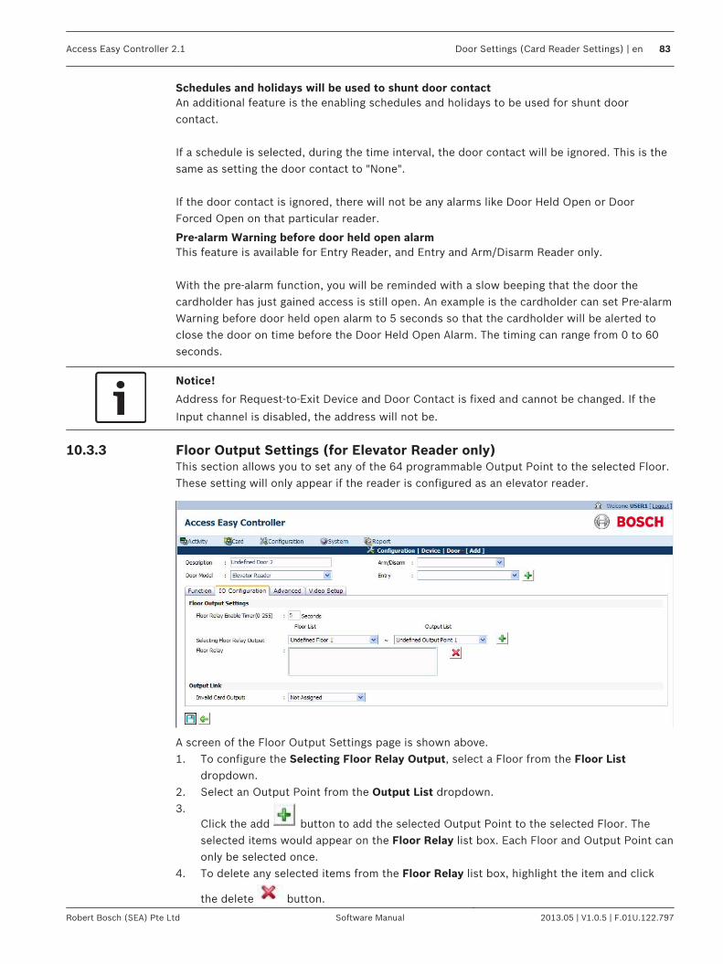
Schedules and holidays will be used to shunt door contactAn additional feature is the enabling schedules and holidays to be used for shunt doorcontact. If a schedule is selected, during the time interval, the door contact will be ignored. This is thesame as setting the door contact to "None". If the door contact is ignored, there will not be any alarms like Door Held Open or DoorForced Open on that particular reader.
Pre-alarm Warning before door held open alarmThis feature is available for Entry Reader, and Entry and Arm/Disarm Reader only. With the pre-alarm function, you will be reminded with a slow beeping that the door thecardholder has just gained access is still open. An example is the cardholder can set Pre-alarmWarning before door held open alarm to 5 seconds so that the cardholder will be alerted toclose the door on time before the Door Held Open Alarm. The timing can range from 0 to 60seconds.
Notice!
Address for Request-to-Exit Device and Door Contact is fixed and cannot be changed. If the
Input channel is disabled, the address will not be.
Floor Output Settings (for Elevator Reader only)This section allows you to set any of the 64 programmable Output Point to the selected Floor.These setting will only appear if the reader is configured as an elevator reader.
A screen of the Floor Output Settings page is shown above.1. To configure the Selecting Floor Relay Output, select a Floor from the Floor List
dropdown.2. Select an Output Point from the Output List dropdown.3.
Click the add button to add the selected Output Point to the selected Floor. Theselected items would appear on the Floor Relay list box. Each Floor and Output Point canonly be selected once.
4. To delete any selected items from the Floor Relay list box, highlight the item and click
the delete button.
10.3.3
Access Easy Controller 2.1 Door Settings (Card Reader Settings) | en 83
Robert Bosch (SEA) Pte Ltd Software Manual 2013.05 | V1.0.5 | F.01U.122.797

5. To configure the Floor Relay Enable Timer, delete the default timing in seconds and entera new timing for it. The default timing is 5 seconds.
Output LinkA screen of the Output Link page is shown in the section Door Output Settings for Entry andExit Reader. These output links allow you to configure individual outputs to trigger when aDoor Forced Open, Door Held Open or Invalid Card alarm occurs at the Reader. In an Entry Reader, and Entry and Exit Reader, it allows you to set any of the 64 programmableOutput Point to Door Forced Alarm Output, Door Held Alarm Output and Invalid Card Output.By default, all the 3 are set to Not Assigned. However, in an Elevator Reader, this section only allows you to set any of the 64programmable Output Point to Invalid Card Output. By default, it is set to Not Assigned.
AdvancedFollowing are the advanced settings for Input Output devices:
PIN Code SettingsThis section allows you to set the parameter on when the Personal Identification Number(PIN) is to be used. A screen of the PIN Code Settings page is shown below.
PIN code not requiredWhen this mode is selected, cardholders accessing this Reader do not have to key in the PINcode.
PIN code required at all timesWhen this mode is selected, cardholders are required to key in the PIN code.
10.3.4
10.4
10.4.1
84 en | Door Settings (Card Reader Settings) Access Easy Controller 2.1
2013.05 | V1.0.5 | F.01U.122.797 Software Manual Robert Bosch (SEA) Pte Ltd

Notice!
In order for the feature to work, the Cardholder's Card + PIN is required on keypad readers
mode must be activated, and the PIN must be set at the card in Card Assignment > Card
functionality page. For the setting of the PIN, refer to Card Functionality, page 53.
PIN code required, except during schedule intervalsWhen this mode is selected, cardholders are not required to key in the PIN code except duringspecific periods defined in the Schedule settings. As an example, the Start and End time for Interval 1 of the Schedule is set to 0830hrs and1730hrs respectively. The Reader status will be set accordingly. The following drawingprovides a pictorial representation of the function.
PIN RequiredPIN Not
RequiredPIN Required
0830hrs 1731hrs
Reader Status
Notice that PIN is required at 1731hrs instead of 1730hrs. The reason is that AEC2.1 takes17:30:59hrs as a valid End time for 1730hrs. This mode is not affected by Holiday setting, i.e.during holiday; it will still use the Day of Week schedule.
Notice!
To use this feature as intended, the cardholder must be given access rights to the reader(s).
In order for the feature to work, the cardholder's Card + PIN is required on keypad readers
mode must be activated.
PIN code required, except during regular schedule intervals and holiday schedule intervalsWhen this mode is selected, the operation is the same as the previous mode, except thatduring holiday the Holiday schedule is used instead of the normal Day of Week schedule.
To set the Schedule1. If selection is made on PIN code required, except during schedule intervals or PIN code
required, except during regular schedule intervals and holiday schedule intervals, theSchedule field must be set.
2. To edit the Schedule, select the appropriate schedule from the Schedule list box.
PIN code only operation using Reader's PIN codeWhen this mode is selected, all cardholders will use a pre-defined Reader's PIN code (defaultcode 1234000) to gain access to the controlled area or to arm/disarm the Alarm Zone. No cardis required. The Reader's PIN code is defined in the Reader's PIN code (1-7 digits) edit field.
Notice!
The PIN code only operation is not supported on the exit reader
To set the Reader's PIN Code1. If the selection is made on PIN code only operation using Reader's PIN code, the Reader's
PIN code (1-7 digits) field be entered.2. To edit the Reader's PIN code, delete the default PIN and enter the new Reader's PIN
code, limited to 7 digits. See NOTICE 1 and 2.
Access Easy Controller 2.1 Door Settings (Card Reader Settings) | en 85
Robert Bosch (SEA) Pte Ltd Software Manual 2013.05 | V1.0.5 | F.01U.122.797

Notice!
NOTICE1: Cardholder can enter from 1 to 7 digits for the Reader's PIN code (default code
1234000).
NOTICE2: For security reason, every character entered for the PIN code is represented by an
asterisk.
Anti-Passback (APB) SettingsA screen of the Anti-Passback (APB) Settings page is shown below.
Anti-Passback (APB) function prevents a cardholder from passing the card to another personto gain access to the door after accessing through it. It is normally implemented in sensitivearea having high security. Three types of APB modes are available namely: - Time Based APB, Soft APB, and Full APB.Each mode provides different level of security and is explained in detail in the following pages.
APB deactivatedIf selected, indicates there is no APB setting for the readers in this AEC2.1. By default, APBdeactivated is checked.
Activate Time Based APBTime Based APB relates to Entry Readers only. If selected, implies the Controller will notaccept the same card until the time set in 'Activate time based schedule' has elapsed. After selecting the option, select the time from the dropdown list provided, the time periodranges from 0 to 60 minutes.
Activate Soft APBSoft APB mode requires a cardholder to present the card at the Entry Reader and Exit Readerat all times. However, if the cardholder follows another person in or out the controlled area,the transaction "Exit Granted, Soft APB" or "Access Granted, Soft APB" will be shown on thecardholder's next exit or entry respectively. The administrator has to Reset APB in order toclear the above transaction. Refer to Reset APB, page 72 for more information.
10.4.2
86 en | Door Settings (Card Reader Settings) Access Easy Controller 2.1
2013.05 | V1.0.5 | F.01U.122.797 Software Manual Robert Bosch (SEA) Pte Ltd
Select the radio button besides 'Activate Soft APB' to activate this option. After selecting thisoption, select the Entry Zone and Exit Zone from the dropdown for this mode to workproperly.
Activate Full APBWhen this mode is selected, the cardholder must first enter using the Entry Reader in order toexit from the corresponding Exit Reader. If cardholder violates this, access will be denied. Theadministrator has to Reset APB before the cardholder can have access again. Refer to ResetAPB, page 72 for more information. Select the radio button besides 'Activate full APB' to activate this option. After checking thisoption, select the Entry Zone and Exit Zone from the dropdown for this mode to workproperly. The main difference between the Soft APB and Full APB is that, for Soft APB, the cardholder isallowed to exit the controlled area via the Exit Reader even if the cardholder entered thecontrolled area previously by following another person. Full APB does not allow that.
Understanding the APB ZoneAPB Zone is applicable to Soft APB and the Full APB mode. AEC2.1 is able to support up to254 Soft APB Entry Zones, 254 Soft APB Exit Zone, 254 Full APB Entry Zone and 254 Full APBExit Zone. Any Reader assigned to operate Soft APB mode or Full APB mode will be given an Entry Zoneand Exit Zone. When a cardholder presents card at Entry Reader #1, the system will verifywhether the cardholder has been registered in Zone 1. If the cardholder has been registered inZone 1, access is granted to the cardholder. When the cardholder opens the door to gainaccess such that the door contact sensing is opened, the cardholder is registered to be inZone 2. However, if the cardholder is verified to be in other zones instead of Zone 1, accesswill be denied to the cardholder.
Notice!
By default all APB settings are based on Door Sensor.
Select Door Contact as None in Device > Door > IO Configuration > Door Input Setting if you
do not want the the APB settings to be based on Door Sensor.
Notice!
In the case that the cardholder is verified to be in Zone 1 and is granted access but the
cardholder did not open the door to gain access, then the cardholder will not be registered in
Zone 2. The cardholder will only be registered in Zone 2 when access is granted. Using this
verification method, no card can bypass any zone to gain access to any other zone. In
addition, zone will only be registered into the card if the cardholder has opened the door
physically (based on door contact sensing).
Dual Card ConfigurationIn the Dual Card Configuration, the Reader can either be configured as Dual Card Modedisabled, After using 2 cards to initiate the access, the system will switch back to single cardaccess or Dual Card access at all time.A screen of the Dual Card Configuration page is shownbelow.
10.4.3
Access Easy Controller 2.1 Door Settings (Card Reader Settings) | en 87
Robert Bosch (SEA) Pte Ltd Software Manual 2013.05 | V1.0.5 | F.01U.122.797

Dual Card Mode disabledIf selected, it implies that no 2 cards are needed to activate the Reader.
After using 2 card to initiate the access, the system will switch back to single card accessIf selected, it implies that after two cards are presented to the same Reader to unlock thedoor, the Reader will switch back to single card access. An example of the scenario would be as follows: In the morning, 2 authorized personnel with dual card function have to present their card atthe high security door Reader before the door can be accessed normally. Subsequently therest of the employees would access the door using their own card. At the end of the day,either of the 2 authorized personnel holding the dual card will have to revert the system backto dual card mode by pressing the <3> key on the Keypad before presenting their cards.
Dual Card access at all timeIf selected, implies that two cards should be presented to the Reader at all times to unlockthe door. This mode works in conjunction with the Dual Card Assignment under the chapter CardAssignment as to check if there is any order in the presentation of cards.
Notice!
When a reader is set with Dual card mode, the cardholders should be configured with either
1st card, 2nd card or don't care card. Accessing the door will require cardholder to present
their cards in the correct order. Example, 1st card followed by 2nd card.
Video SetupThe video setup tab is used to configure cameras to the readers. The video verification cameraand the surveillance camera, for the reader are set in the video setup tab. A maximum of three cameras can be configured to a reader.
10.5
88 en | Door Settings (Card Reader Settings) Access Easy Controller 2.1
2013.05 | V1.0.5 | F.01U.122.797 Software Manual Robert Bosch (SEA) Pte Ltd
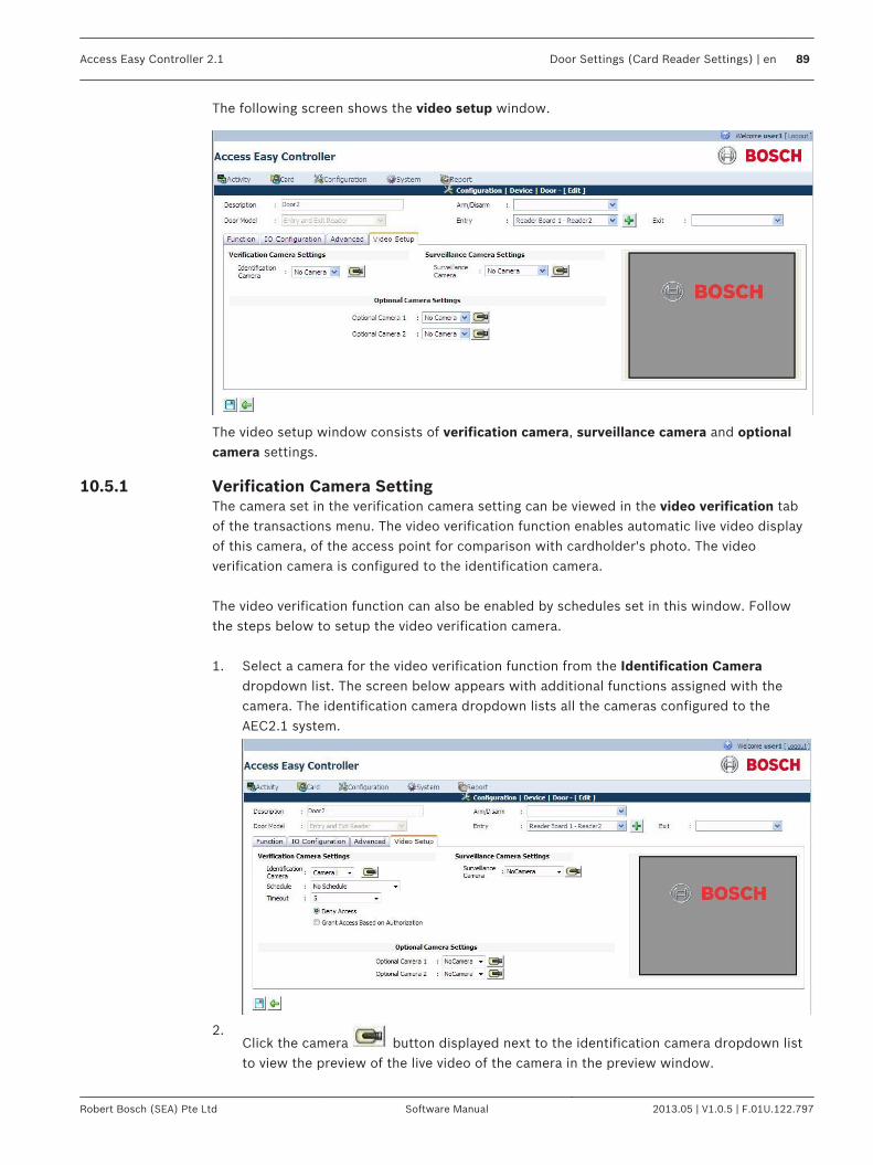
The following screen shows the video setup window.
The video setup window consists of verification camera, surveillance camera and optionalcamera settings.
Verification Camera SettingThe camera set in the verification camera setting can be viewed in the video verification tabof the transactions menu. The video verification function enables automatic live video displayof this camera, of the access point for comparison with cardholder's photo. The videoverification camera is configured to the identification camera. The video verification function can also be enabled by schedules set in this window. Followthe steps below to setup the video verification camera. 1. Select a camera for the video verification function from the Identification Camera
dropdown list. The screen below appears with additional functions assigned with thecamera. The identification camera dropdown lists all the cameras configured to theAEC2.1 system.
2.Click the camera button displayed next to the identification camera dropdown listto view the preview of the live video of the camera in the preview window.
10.5.1
Access Easy Controller 2.1 Door Settings (Card Reader Settings) | en 89
Robert Bosch (SEA) Pte Ltd Software Manual 2013.05 | V1.0.5 | F.01U.122.797

3. Select a schedule from the Schedule dropdown to activate the video verification functionat the set schedule. When a schedule is set, the video verification feature will be activeduring the set time only and at other times the door behaves like a normal access door.Select No Schedule if you do not want to set a schedule for the activation of the videoverification feature.
4. Select a time from the timeout dropdown. This timeout period is set for the operator togrant or deny access to the cardholder within the set time. If the time-out occurs, grantaccess or deny access is provided according to the cardholder's access permissions. Thetime-out period can range between 0 and 60 seconds.
5. Select the radio button Deny access if you want to deny door access to the cardholderafter the time out duration. If this option is enabled the cardholder will be denied accesseven if the cardholder has the access rights to the door. If this option is enabled thecardholder can access the door only if the operator grants access manually.
6. Select the radio button Grant Access based on Authorization if you want the cardholderto access the door after the time out duration.
Refer to Video Verification, page 31 for more details on video verification functions
Surveillance Camera SettingThe camera set in the surveillance camera setting is used for the surveillance tab in thetransactions window. The surveillance window will pop up automatically when an alarm eventis triggered by the AEC2.1 system in the configured location. Refer to Surveillance, page 35 formore information about the surveillance window functions. Follow the steps below to setupthe video surveillance window. 1. Select a camera for the video surveillance function from the Surveillance Camera
dropdown list. The surveillance camera dropdown lists all the cameras configured to theAEC2.1 system.
2.Click the camera button to view the preview of the live video in the previewwindow.
Optional Camera SettingAEC2.1 system supports a maximum of three cameras to a reader. The set optional camerasare available in the video verification and surveillance function. Follow the steps below to setthe remaining cameras to the AEC2.1 system. 1. Select a camera from the Optional Camera 1 dropdown list. The Optional camera
dropdown lists all the cameras configured to the AEC2.1 system.2.
Click the camera button to see the preview of the live video in the preview window.3. Repeat step 1 and 2 for the Optional camera 2 option. Leave the optional cameras
setting as No Camera if the reader is not configured to other cameras.This section completes the Door settings for the AEC2.1 system.
Notice!
If an optional camera is configured for the event location without configuring a surveillance
camera, it is considered as no surveillance camera is configured for the event location.
10.5.2
10.5.3
90 en | Door Settings (Card Reader Settings) Access Easy Controller 2.1
2013.05 | V1.0.5 | F.01U.122.797 Software Manual Robert Bosch (SEA) Pte Ltd

VideosAEC2.1 provides seamless integration with selected IP cameras, encoders, digital videorecorder and network video recorder. The video features include viewing Live and Playbackvideo, and comparing the live and playback videos. The video verification feature enablesautomatic live video display of the access point for comparison with cardholder's photo.
Notice!
Video integration features are available on Windows 7/XP OS only.
AEC2.1 supports up to a maximum of three live video cameras for each device. The videos arerecorded in the video device and not on the AEC system. The following software tools must be loaded in the remote PC before using the video featuresin AEC2.1:– DirectX– Video card that supports DirectX– Microsoft .NET Framework 3.0
(Microsoft .NET Framework 3.5 is required for VideoSDK 5.x) Note: The ActiveX and Video SDK is installed automatically when the AEC2.1 system isconfigured to a camera. If the Video SDK is not installed automatically then you can install itfrom the utility CD or retrieve them from the VideoSDK page. Refer to Video SDK, page 161 inAdvance settings for more information. The AEC2.1 integrates with the following video devices.
IP Camera : AutoDome IP, Dinion IP, FlexiDome IP
Encoders : VideoJet X10, VIP10, VIP-X
DVR/NVR : DiBos, DivarXF, Vidos NVR4.0, Divar 400/600/700, BRS
HD Camera : Works with VideoSDK 5.x only
Installing DirectX and Video SDKDirectX and Video SDK must be installed in the system for the video features to be accessible.Video features are available in Windows 7/XP OS only.
Installing Video SDKRefer to Installation Procedure for VideoSDK, page 19 to install VideoSDK.
Web Browser Settings for Accessing Video Features in AEC2.1Proceed as follows to make the necessary web browser settings for the working of the videofeatures available in AEC2.1.
11
11.1
11.1.1
11.2
Access Easy Controller 2.1 Videos | en 91
Robert Bosch (SEA) Pte Ltd Software Manual 2013.05 | V1.0.5 | F.01U.122.797

1. Launch Internet Explorer and in the menu bar select Tools > Internet Options. Thescreen below appears.
92 en | Videos Access Easy Controller 2.1
2013.05 | V1.0.5 | F.01U.122.797 Software Manual Robert Bosch (SEA) Pte Ltd

2. In the Internet options window select the tab Security and select the icon Trusted Sitesin Select a zone to view or change security settings as shown below.
Access Easy Controller 2.1 Videos | en 93
Robert Bosch (SEA) Pte Ltd Software Manual 2013.05 | V1.0.5 | F.01U.122.797

3. Click the button sites and the Trusted Sites window pops up as shown below. Enter theIP address of the panel in the Add this website to the zone window. Click the Addbutton.
4. The added IP address now appears in the Websites window as shown below.
5. Click the close button to return to the security tab in the Internet Options window. Clickthe button Custom Level in the Security level for this zone window. The screen belowappears.
94 en | Videos Access Easy Controller 2.1
2013.05 | V1.0.5 | F.01U.122.797 Software Manual Robert Bosch (SEA) Pte Ltd

Select the checkbox besides Enable for all the functions below ActiveX controls andplug-ins. Click the OK button repeatedly to exit from the Internet Options window.
Video ConfigurationThis section describes the steps to setup a camera on the AEC2.1 system. The videoconfiguration menu consists of three tabs namely Camera, Device Type and Miscellaneous.The three submenus are explained in detail in the following pages.
Device Type AdditionThe device type refers to the type of the camera being used, it can either be a IP Camera,Encoder camera etc. Camera device type is necessary to add a camera to the AEC 2.1 system.By default some of the camera types are defined in the AEC2.1 system.
Notice!
Contact the nearest BOSCH Security Systems representative to add a new Device Type to
the AEC2.1 system.
Notice!
Follow the steps below to configure the device type only if the Auto Detection option is not
available.
Click the link Configuration > Videos to add a new camera device type to the AEC2.1 system.In the Configuration | Video main page select the tab Device Type. The screen below appears.
11.3
11.3.1
Access Easy Controller 2.1 Videos | en 95
Robert Bosch (SEA) Pte Ltd Software Manual 2013.05 | V1.0.5 | F.01U.122.797

The Device type main page lists the existing Device name and Device type available in AEC2.1system. Cardholder’s having the access rights to add video devices can add new device typeto the system.
Click the add button to add a new video device. The screen below appears.
Enter the Device Name in the device name field, Device ID in the device id field, and select a
Device Type from the device type dropdown provided. Click the save button to save the
values added. Click the back button to cancel the changes and display the devicesettings main page.
Notice!
The Device ID is provided by the BOSCH Security Systems. Contact the nearest BOSCH
Security Systems representative to obtain a Device ID.
In the Device Settings main page you can edit or delete an existing video device. Click the edit
button to edit the settings of the existing video device. The edit device page is same asthe add device web page. Refer to the previous paragraphs for more information.
Click the delete button to delete an existing video device.
Adding Camera to AEC2.1After adding the camera device type, cameras can be configured on the AEC2.1 system. Selectthe Camera tab from Configuration > Video main page to add cameras to the AEC2.1 system. The screen below shows the default page for the camera tab.The camera tab is the defaultpage for Video Configuration menu.
11.3.2
96 en | Videos Access Easy Controller 2.1
2013.05 | V1.0.5 | F.01U.122.797 Software Manual Robert Bosch (SEA) Pte Ltd

The Camera main page shows a list of cameras configured in AEC2.1 system. The camera main
page consists of two function buttons namely the add button and the Auto Detection
Camera button . Auto Detection
Click the auto detection button to detect the cameras available in the system. Thescreen below shows the auto detection camera page.
Note: For Video SDK 5.x, Device Type will be shown in place of Device ID in the list detectedcameras. Once the Auto detection button is clicked the above window pops up and starts searching thedevice types available. Enter the username and password for the device types in the usernameand password field. You can search cameras without entering the username and password,
but PTZ cameras require a username and password. Click the search cameras icon tosearch the cameras available in the selected device type. The screen below shows the auto detection window with the list of cameras available.
Access Easy Controller 2.1 Videos | en 97
Robert Bosch (SEA) Pte Ltd Software Manual 2013.05 | V1.0.5 | F.01U.122.797
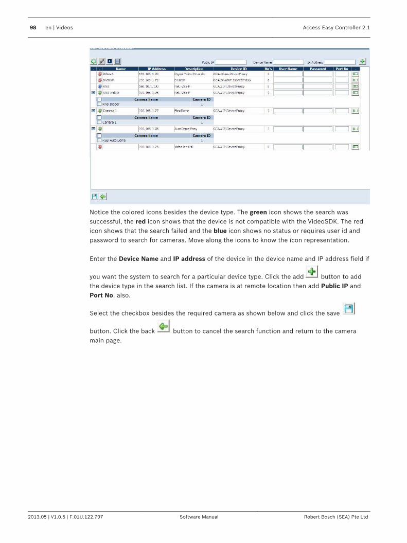
Notice the colored icons besides the device type. The green icon shows the search wassuccessful, the red icon shows that the device is not compatible with the VideoSDK. The redicon shows that the search failed and the blue icon shows no status or requires user id andpassword to search for cameras. Move along the icons to know the icon representation. Enter the Device Name and IP address of the device in the device name and IP address field if
you want the system to search for a particular device type. Click the add button to addthe device type in the search list. If the camera is at remote location then add Public IP andPort No. also.
Select the checkbox besides the required camera as shown below and click the save
button. Click the back button to cancel the search function and return to the cameramain page.
98 en | Videos Access Easy Controller 2.1
2013.05 | V1.0.5 | F.01U.122.797 Software Manual Robert Bosch (SEA) Pte Ltd

The selected cameras are now available in the camera main page as shown below.
If you click the auto detection button again you will notice that the checkbox besides theselected cameras will be disabled as shown below.
Manual Addition
Access Easy Controller 2.1 Videos | en 99
Robert Bosch (SEA) Pte Ltd Software Manual 2013.05 | V1.0.5 | F.01U.122.797

Click the add button to add a new camera to the AEC2.1 system. The screen belowappears.
Select the device type from Select the type dropdown. Refer to the Section 13.3.1 DeviceType addition, Page 128 for more details on adding new device type to the AEC2.1 system. Ifthe user selects Dibos then the port no automatically sets to 8080.
In the Encoder Settings window enter the Camera Name in the camera name field, Camera'sIP address in the camera IP field, and the Camera number in the camera no. field. The camera number can range from 0 to 64. If the camera ID is set to 0 the system will accessthe camera by camera name. The exact camera name has to be entered to access the camera.
Notice!
A maximum of 128 cameras can be configured in the AEC2.1 system.
Select the checkbox besides Is PTZ Camera if the camera is a Pan Tilt Zoom camera. Enter auser name and password for the camera. This user name and password is necessary tocontrol the camera and to view the video of this camera.
100 en | Videos Access Easy Controller 2.1
2013.05 | V1.0.5 | F.01U.122.797 Software Manual Robert Bosch (SEA) Pte Ltd

The server type refers to the storage of the recorded videos. Select a storage place for therecorded videos from the dropdown. If you select the server type as VIDOS the followingscreen appears. Enter the Server IP, Username and password in the appropriate fields.
Select No Storage option from the Server type dropdown if there is no video storage device.
After entering all the values click the save button to save the settings. Click the back
button to cancel the changes and return to the camera main page.
In the Camera main page you can edit or delete an existing camera. Click the edit buttonto edit the existing camera settings. The edit camera page is same as the add camera page.
Refer to the earlier paragraphs for more information.Click the delete button to delete anexisting camera.
MiscellaneousThe miscellaneous tab in Configuration > Video main page refers to the event pre and postrecording timer settings and the location configuration for snapshot and export video. The pre and post timer settings are used in the playback option of the video settings. Thescreen below shows the main page for the miscellaneous option.
11.3.3
Access Easy Controller 2.1 Videos | en 101
Robert Bosch (SEA) Pte Ltd Software Manual 2013.05 | V1.0.5 | F.01U.122.797

In the event timer settings window enter the pre event and post event duration. For exampleset 10 seconds in the pre timer and post timer settings. At any time if you view a playbackvideo, the video will start playing the video 10 seconds before the event and stop 10 secondsafter the event. The maximum number of seconds for pre event and post event duration is 180seconds. Type in a location for storing the snapshot and exported videos from the AEC2.1 system to the
PC in the Snapshot/Export Video location field. Click the save button to save thesettings.
Notice!
The Snapshot/Export Video location field must not be any drives, for example "C:\", "D:\" and
so on. It should be some folders inside the drives, for example "C:\Temp\” and so on.
After adding the video device and camera to the AEC2.1 system you can now go ahead andconfigure the camera to a reader.
102 en | Videos Access Easy Controller 2.1
2013.05 | V1.0.5 | F.01U.122.797 Software Manual Robert Bosch (SEA) Pte Ltd

Input/Output SetupThis chapter explains the steps to set the Input and Output points.
Input SetupThe AEC2.1 has 64 user programmable Input Points that will be used for Alarm Monitoringpurposes. The address for these Input Points ranges from 33 to 64 and is available on the 8-I/O board. Each board provides up to eight Input Points. These Input Points can be assigned into a Group (called an Alarm Zone) or as an Individual.Both the types provide the same function, the only difference is the way each is being armed/disarmed. AEC2.1 allows you to configure up to eight Alarm Zones. An Alarm Zone (see NOTICE) can be armed/disarmed by the following methods: -– manually via a dedicated Arm/Disarm Reader, or– manually via the web page (Input Control), or– system control based on Schedule Intervals.An Individual Input Point can be armed/disarmed only by Schedule intervals. All Input Points, Group or Individual, can be configured to trigger 1 to 4 Output Points (ofthe8-I/O board) for the purpose of status indication. The Outputs are labelled as: -
Status Description
Alarm Status Turns “ON” during an Alarm condition.
Arm/Disarm Status Turns “ON” when it is Armed.
Ready Status Turns “ON” when the Input Point is not in the normal condition.It is said to be Not Ready for Arming.
Bypass Status Turns “ON” when the Input Point is Bypassed.
Any alarm detected by any of the Input Points would also trigger the Common Alarm Outputrelay, at address 8, and is only restored when all the Input Points is restored back to Normalstate.
Notice!
The Input Control web page displays the status of the Alarm Zones only, and status of
Individual Input Points will not be displayed.
All Input Points configured to an Alarm Zone follows the First Input Point's setting for Arm
Delay, Alarm Delay, and Schedule of that Zone.
The paragraph below provides a brief description of how the AEC2.1 interprets the ScheduleIntervals for Input Points arming and disarming statuses. For example,If the setting for Schedule is: -Interval 1 Start 0830 hrs End 1730 hrsInterval 2, 3,and 4 has no setting. When the Schedule is tied to Input Point #1, the point will arm and disarm accordingly.
12
12.1
Access Easy Controller 2.1 Input/Output Setup | en 103
Robert Bosch (SEA) Pte Ltd Software Manual 2013.05 | V1.0.5 | F.01U.122.797

Armed
0830hrs 1731hrs
Input Point # 1
Status ArmedDisarmed
0000hrs 2359hrs
Take note that the Input Point is disarmed at exactly 0830 hrs but re-armed at 1731 hrs aminute delay as compared to the Schedule setting. The reason is that AEC2.1 takes 17:30:59hrs as a valid End time for 1730 hrs.
Notice!
Before you configure any Input Point(s), please ensure that the Alarm Monitoring Device with
the EOL resistor is in place with the necessary logic inversion on the Input Point
Configuration web page.
To Activate the Input Setup1. Click the link Configuration > Device > Input/Output. In the Input/Output main page
select the tab Input. The Input page is the default page of the Input/Output menu. Thescreen below shows the main page of the Input Point menu.
12.1.1
104 en | Input/Output Setup Access Easy Controller 2.1
2013.05 | V1.0.5 | F.01U.122.797 Software Manual Robert Bosch (SEA) Pte Ltd

2.In the Input main page click the button to add a new input point. The screen belowappears.
3.Select the check box besides the Input points to be configured. Click the edit
button to edit the description of the input point. Click the save button to save the
input point settings or click the back button to return to the Input point main page.
The added Input point is now available in the Input point main page. After adding the
input point to the device click the edit button to edit the settings of the configuredinput point.
4.New input points can also be configured by clicking the edit button besides anyUndefined Input Point. The input point main page consists of two tabs namely Input andCamera Input. Select the tab Input.
Access Easy Controller 2.1 Input/Output Setup | en 105
Robert Bosch (SEA) Pte Ltd Software Manual 2013.05 | V1.0.5 | F.01U.122.797
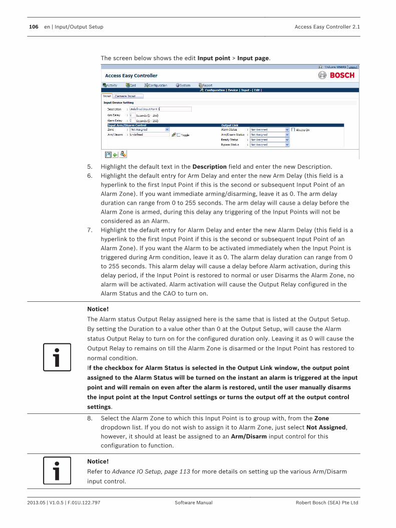
The screen below shows the edit Input point > Input page.
5. Highlight the default text in the Description field and enter the new Description.6. Highlight the default entry for Arm Delay and enter the new Arm Delay (this field is a
hyperlink to the first Input Point if this is the second or subsequent Input Point of anAlarm Zone). If you want immediate arming/disarming, leave it as 0. The arm delayduration can range from 0 to 255 seconds. The arm delay will cause a delay before theAlarm Zone is armed, during this delay any triggering of the Input Points will not beconsidered as an Alarm.
7. Highlight the default entry for Alarm Delay and enter the new Alarm Delay (this field is ahyperlink to the first Input Point if this is the second or subsequent Input Point of anAlarm Zone). If you want the Alarm to be activated immediately when the Input Point istriggered during Arm condition, leave it as 0. The alarm delay duration can range from 0to 255 seconds. This alarm delay will cause a delay before Alarm activation, during thisdelay period, if the Input Point is restored to normal or user Disarms the Alarm Zone, noalarm will be activated. Alarm activation will cause the Output Relay configured in theAlarm Status and the CAO to turn on.
Notice!
The Alarm status Output Relay assigned here is the same that is listed at the Output Setup.
By setting the Duration to a value other than 0 at the Output Setup, will cause the Alarm
status Output Relay to turn on for the configured duration only. Leaving it as 0 will cause the
Output Relay to remains on till the Alarm Zone is disarmed or the Input Point has restored to
normal condition.
If the checkbox for Alarm Status is selected in the Output Link window, the output point
assigned to the Alarm Status will be turned on the instant an alarm is triggered at the input
point and will remain on even after the alarm is restored, until the user manually disarms
the input point at the Input Control settings or turns the output off at the output control
settings.
8. Select the Alarm Zone to which this Input Point is to group with, from the Zonedropdown list. If you do not wish to assign it to Alarm Zone, just select Not Assigned,however, it should at least be assigned to an Arm/Disarm input control for thisconfiguration to function.
Notice!
Refer to Advance IO Setup, page 113 for more details on setting up the various Arm/Disarm
input control.
106 en | Input/Output Setup Access Easy Controller 2.1
2013.05 | V1.0.5 | F.01U.122.797 Software Manual Robert Bosch (SEA) Pte Ltd
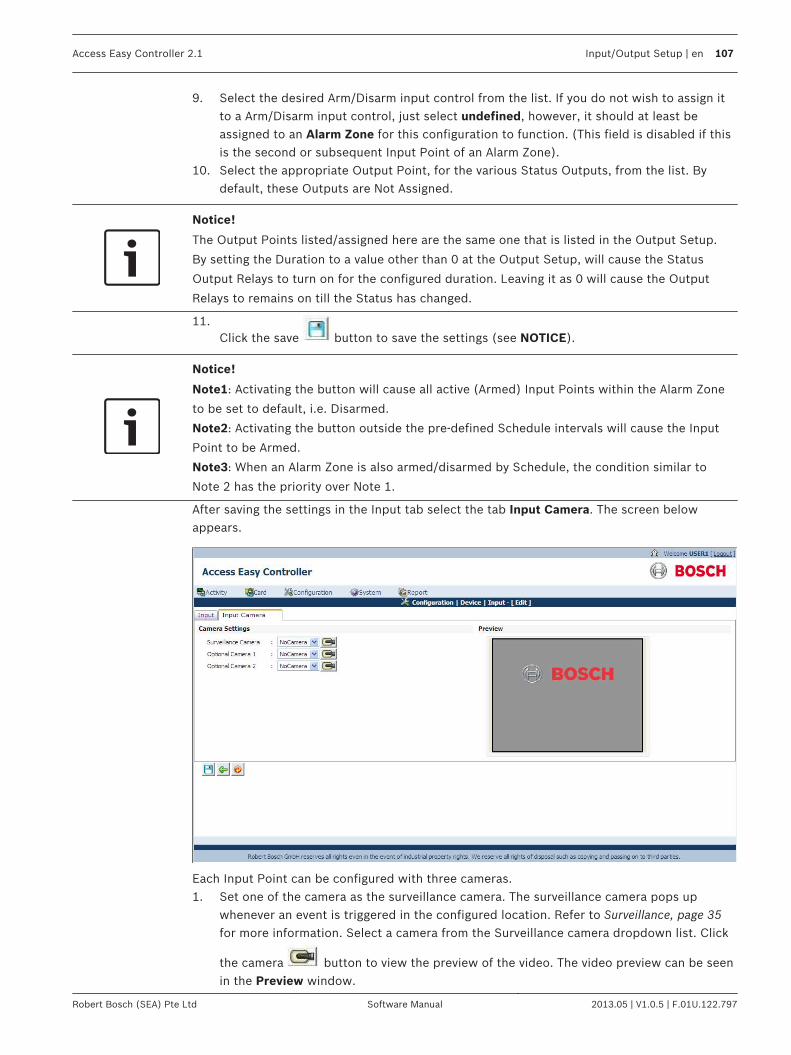
9. Select the desired Arm/Disarm input control from the list. If you do not wish to assign itto a Arm/Disarm input control, just select undefined, however, it should at least beassigned to an Alarm Zone for this configuration to function. (This field is disabled if thisis the second or subsequent Input Point of an Alarm Zone).
10. Select the appropriate Output Point, for the various Status Outputs, from the list. Bydefault, these Outputs are Not Assigned.
Notice!
The Output Points listed/assigned here are the same one that is listed in the Output Setup.
By setting the Duration to a value other than 0 at the Output Setup, will cause the Status
Output Relays to turn on for the configured duration. Leaving it as 0 will cause the Output
Relays to remains on till the Status has changed.
11.Click the save button to save the settings (see NOTICE).
Notice!
Note1: Activating the button will cause all active (Armed) Input Points within the Alarm Zone
to be set to default, i.e. Disarmed.
Note2: Activating the button outside the pre-defined Schedule intervals will cause the Input
Point to be Armed.
Note3: When an Alarm Zone is also armed/disarmed by Schedule, the condition similar to
Note 2 has the priority over Note 1.
After saving the settings in the Input tab select the tab Input Camera. The screen belowappears.
Each Input Point can be configured with three cameras.1. Set one of the camera as the surveillance camera. The surveillance camera pops up
whenever an event is triggered in the configured location. Refer to Surveillance, page 35for more information. Select a camera from the Surveillance camera dropdown list. Click
the camera button to view the preview of the video. The video preview can be seenin the Preview window.
Access Easy Controller 2.1 Input/Output Setup | en 107
Robert Bosch (SEA) Pte Ltd Software Manual 2013.05 | V1.0.5 | F.01U.122.797

2.Select the second camera from the Optional Camera1 dropdown list. Click the button to view the preview of the video. The video preview can be seen in the Previewwindow.
3.Select the third camera from the Optional Camera2 dropdown list. Click the buttonto view the preview of the video. The video preview can be seen in the Preview window.
Click the save button to save the settings. Click the back button to cancel thesettings and return to the Input main page. At any point of time click the reset to factory
default to reset the input points to factory default.
Output SetupThe AEC2.1 has 64 user programmable Output Points that will be used for Utility Triggeringpurposes. The address for these Input Points ranges from 33 to 64 and is available on the I/OCard. Each card provide up to 8 Output Points. The Output Points are triggered manually via the web page, or based on Schedule Intervals, oris triggered by an Input Point as a Status indicator. The status of all the Output Points is displayed in the Output Control web page except thosepoints that are triggered by Input Points. The paragraph below provides a brief description of how the AEC2.1 interprets the ScheduleIntervals for Output Points triggering status. For example,If the setting for Schedule is: -Interval 1Start 0830 hrs, End 1730 hrsInterval 2, 3,and 4 has no setting. When the Schedule is tied to Output Point #1, the point will turn on and off accordingly.
Off
0830hrs 1731hrs
Output Point # 1
Status OffOn
0000hrs 2359hrs
Take note that the Output Point switches On at exactly 0830hrs but switches Off at 1731hrsaminute delay as compared to the Schedule setting. The reason is that AEC2.1 takes 17:30:59hrs as a valid End time for 1730 hrs.
To Activate the Output SetupThe Input Setup can be activated only from the menu item page.
12.2
12.2.1
108 en | Input/Output Setup Access Easy Controller 2.1
2013.05 | V1.0.5 | F.01U.122.797 Software Manual Robert Bosch (SEA) Pte Ltd

1. Click Configuration > Device > Input/Output. In the Input/Output main page select thetab Output. The screen below shows the main page of the Output Point menu
2.In the Output main page click the button to add a new output point. The screenbelow appears.
3.Select the check box besides the output points to be configured. Click the edit
button to edit the description of the output point. Click the save button to save the
output point settings or click the back button to return to the output point mainpage. The added output point is now available in the output point main page.
After adding the output point to the device click the edit button to edit the settingsof the configured output point.
Access Easy Controller 2.1 Input/Output Setup | en 109
Robert Bosch (SEA) Pte Ltd Software Manual 2013.05 | V1.0.5 | F.01U.122.797

4.New output points can also be configured by clicking the edit button besides anyUndefined Output Point.
The screen below shows the edit Output point page.
5. Highlight the default text in the Description field and enter the new Description.6. Highlight the default entry for Duration and enter the new Duration (see NOTICE).
Notice!
This setting for the Duration field is applicable for Manual Output Control (refer to the
Chapter on Output Control). User can force the Output Point(s) to toggle its current state for
the duration specified here. User could also assign the Output Point as a Status Output for
the Input Point, however, if the Duration field has a value other than 0, the Output Point will
not remains on when the respective status is activated, instead, it will turns on only for the
duration as specified here.
If Duration Field is Always On, output point will be turned on infinitely when triggered until
the user turns it off manually at the Output Control settings. E.g. If Output Point 1 is
assigned to Door Forced Alarm Output of Reader 1, when door at Reader 1 is forced open,
Output Point 1 will be turned on, and will remain on even after the door is closed, until the
user turns it off manually at the output control settings.
7. Select the appropriate Schedule from the list. By default, an unused Output Point is tiedto No Schedule i.e. the Output will not be triggered.
8.Click the save button.
Notice!
Activating the button within the pre-defined Schedule intervals will cause the Output Relay to
turn On.
9.Click the save button to save the settings or click the back button to return to
Output main page. At any point of time click the reset to factory default button toreset the output points to factory default.
Disable Activity from Output PointThis will allow the user to disable any of the 64 output points activity to be logged, especiallywhen they are activated by other type of function or elevator operation which do not requirelogging. This means that the activity transactions associated with the Output Point will notbelogged at the Transactions page.
12.2.2
110 en | Input/Output Setup Access Easy Controller 2.1
2013.05 | V1.0.5 | F.01U.122.797 Software Manual Robert Bosch (SEA) Pte Ltd

1. To use this feature, select an Output Point that you do not want its activity transactionsto be logged.
2. Select a schedule from the output scheduling dropdown list.3. Select the Disable Transaction at Activity checkbox besides the schedule dropdown as
shown below.
4.Click the save button to save the settings or click the back button to return to
the output point main page. At any point of time, click the reset to factory default button to reset the output points to factory default.
After saving the settings in the output tab select the tab Output Camera. The screen belowappears.
Each Output Point can be configured with three cameras. 1. Set one of the camera as the surveillance camera. The surveillance camera pops up
whenever an event is triggered in the configured location. Refer to Surveillance, page 35for more information. Select a camera from the Surveillance camera dropdown list. Click
the button to view the preview of the video. The video preview can be seen in thepreview window.
2.Select the second camera from the Optional Camera1 dropdown list. Click the button to view the preview of the video. The video preview can be seen in the previewwindow.
3.Select the third camera from the Optional Camera2 dropdown list. Click the buttonto view the preview of the video. The video preview can be seen in the preview window.
Access Easy Controller 2.1 Input/Output Setup | en 111
Robert Bosch (SEA) Pte Ltd Software Manual 2013.05 | V1.0.5 | F.01U.122.797

Click the save button to save the settings or click the back button to return to the
output point main page. At any point of time click the reset to factory default button toreset the output points to factory default.Click the save button to save the settings.
112 en | Input/Output Setup Access Easy Controller 2.1
2013.05 | V1.0.5 | F.01U.122.797 Software Manual Robert Bosch (SEA) Pte Ltd
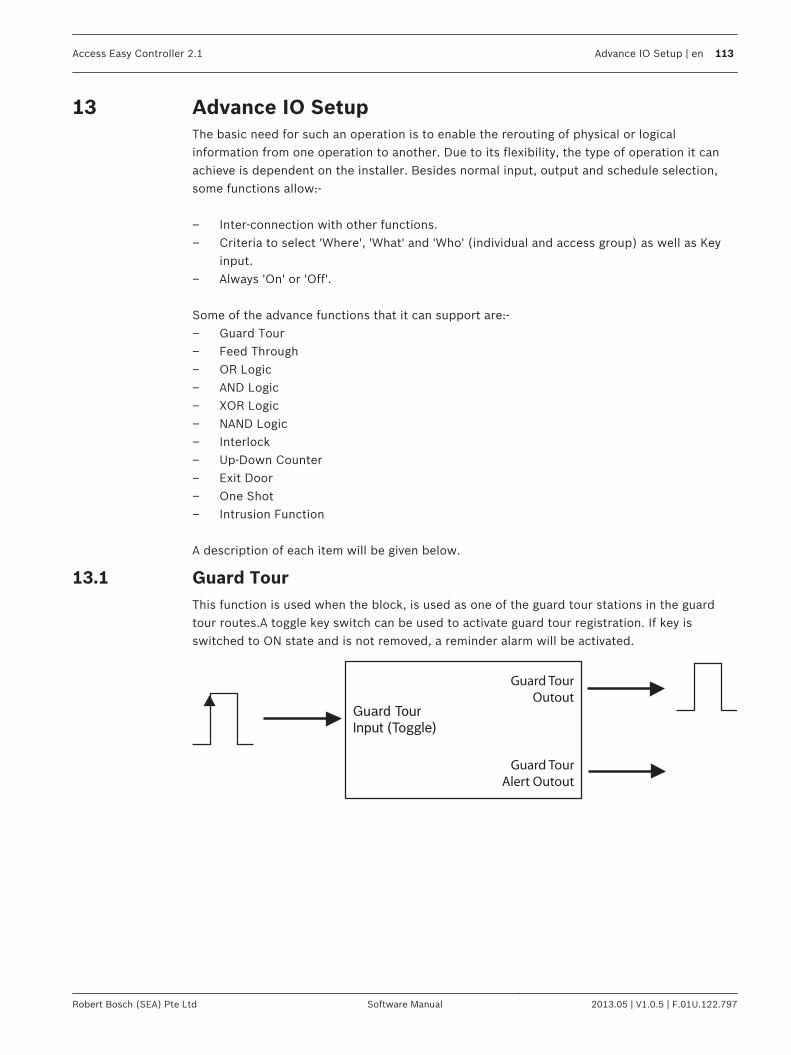
Advance IO SetupThe basic need for such an operation is to enable the rerouting of physical or logicalinformation from one operation to another. Due to its flexibility, the type of operation it canachieve is dependent on the installer. Besides normal input, output and schedule selection,some functions allow:- – Inter-connection with other functions.– Criteria to select 'Where', 'What' and 'Who' (individual and access group) as well as Key
input.– Always 'On' or 'Off'. Some of the advance functions that it can support are:-– Guard Tour– Feed Through– OR Logic– AND Logic– XOR Logic– NAND Logic– Interlock– Up-Down Counter– Exit Door– One Shot– Intrusion Function A description of each item will be given below.
Guard TourThis function is used when the block, is used as one of the guard tour stations in the guardtour routes.A toggle key switch can be used to activate guard tour registration. If key isswitched to ON state and is not removed, a reminder alarm will be activated.
Guard TourInput (Toggle)
Guard Tour
Outout
Guard Tour
Alert Outout
13
13.1
Access Easy Controller 2.1 Advance IO Setup | en 113
Robert Bosch (SEA) Pte Ltd Software Manual 2013.05 | V1.0.5 | F.01U.122.797

Input/Output Description
Guard Tour Input This input is edge triggered from '0' to '1' (leading edge) &toggling.A key switch can be connected to this input.
Guard Tour Output A LED is normally connected to this output. The LED will beturned on for the duration when the guard tour input istriggered.
Guard Tour Alert Output A LED is normally connected to this output. The LED will beturned on when the Input Duration has lapsed and the keyswitch, which is switched to ON state, is still not removed. Areminder alarm will be activated.
The timing diagram below gives a graphical description of the function.
In the timing diagram above, Guard Tour Input at transition A and B will cause the Guard TourOutput to be turned On for the duration when the Guard Tour Input is triggered. When theInput Duration, t1, has lapsed and the Guard Tour Input is still at High (1), the Guard TourAlert Output will be turned On until the Guard Tour Input is switched to Low (0). Whereas fort2, the Input Duration is such that the Guard Tour Input has already been switched to Low (0)before the Input Duration, t2, has lapsed. Therefore the Guard Tour Alert Output is nottriggered. In practical scenario, a key switch is normally connected to the Guard Tour Input, a LEDconnected to Guard Tour Output and a LED and/or an alarm is connected to the Guard TourAlert Output. When the guard goes for his daily routine, he would turn his key switch to Onstate. This will cause the LED in the Guard Tour Output to be turned On. And if the key is notremoved after the Input Duration has lapsed, the LED in the Guard Tour Alert Output will beturned On and the alarm will be activated to remind the guard that he has not removed thekey from the key switch.
Feed ThroughThis function is used when the output of a function block has to be fed into the input ofanother function block for further action.
13.2
114 en | Advance IO Setup Access Easy Controller 2.1
2013.05 | V1.0.5 | F.01U.122.797 Software Manual Robert Bosch (SEA) Pte Ltd
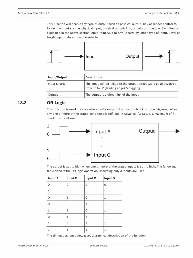
This function will enable any type of output such as physical output, link or reader control tofollow the input such as physical input, physical output, link, criteria or schedule. Each item isexplained in the above section Input Point Able to Arm/Disarm by Other Type of Input. Level ortoggle input behavior can be selected.
Input Output
Input/Output Description
Input source The input will be linked to the output directly.It is edge triggeredfrom '0' to '1' (leading edge) & toggling.
Output The output is a direct link of the input.
OR LogicThis function is used in cases whereby the output of a function block is to be triggered whenany one or more of the stated conditions is fulfilled. In Advance I/O Setup, a maximum of 7conditions is allowed.
Input A Output
Input G
.
.
.
.
1
1
0
0
The output is set to high when one or more of the stated inputs is set to high. The followingtable depicts the OR logic operation, assuming only 3 inputs are used.
Input A Input B Input C Input D
0 0 0 0
1 0 0 1
0 1 0 1
0 0 1 1
1 1 0 1
0 1 1 1
1 0 1 1
1 1 1 1
The timing diagram below gives a graphical description of the function.
13.3
Access Easy Controller 2.1 Advance IO Setup | en 115
Robert Bosch (SEA) Pte Ltd Software Manual 2013.05 | V1.0.5 | F.01U.122.797
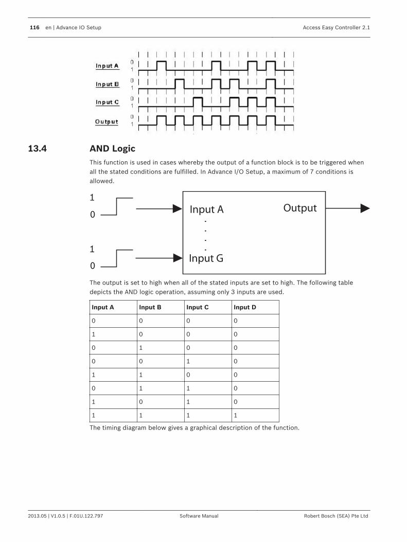
AND LogicThis function is used in cases whereby the output of a function block is to be triggered whenall the stated conditions are fulfilled. In Advance I/O Setup, a maximum of 7 conditions isallowed.
Input A Output
Input G
.
.
.
.
1
1
0
0
The output is set to high when all of the stated inputs are set to high. The following tabledepicts the AND logic operation, assuming only 3 inputs are used.
Input A Input B Input C Input D
0 0 0 0
1 0 0 0
0 1 0 0
0 0 1 0
1 1 0 0
0 1 1 0
1 0 1 0
1 1 1 1
The timing diagram below gives a graphical description of the function.
13.4
116 en | Advance IO Setup Access Easy Controller 2.1
2013.05 | V1.0.5 | F.01U.122.797 Software Manual Robert Bosch (SEA) Pte Ltd
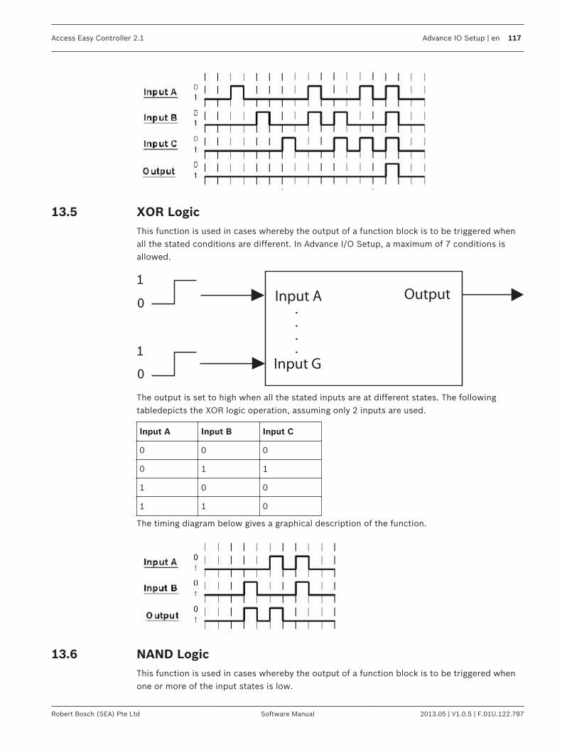
XOR LogicThis function is used in cases whereby the output of a function block is to be triggered whenall the stated conditions are different. In Advance I/O Setup, a maximum of 7 conditions isallowed.
Input A Output
Input G
.
.
.
.
1
1
0
0
The output is set to high when all the stated inputs are at different states. The followingtabledepicts the XOR logic operation, assuming only 2 inputs are used.
Input A Input B Input C
0 0 0
0 1 1
1 0 0
1 1 0
The timing diagram below gives a graphical description of the function.
NAND LogicThis function is used in cases whereby the output of a function block is to be triggered whenone or more of the input states is low.
13.5
13.6
Access Easy Controller 2.1 Advance IO Setup | en 117
Robert Bosch (SEA) Pte Ltd Software Manual 2013.05 | V1.0.5 | F.01U.122.797

Input A Output
Input G
.
.
.
.
1
1
0
0
The output is set to high when one or more of the input states is low. The following tabledepicts the NAND logic operation, assuming only 2 inputs are used.
Input A Input B Input C
0 0 1
0 1 1
1 0 1
1 1 0
The timing diagram below gives a graphical description of the function.
Interlock/Man Trap1. Interlock Operation
All doors will remain closed and unlocked. Opening any of the doors will cause all otherdoors to be locked until the opened door returns to the closed position. In AEC2.1, amaximum of 5 doors can be configured.Examples of such applications are darkrooms, laboratories, clean rooms, airlock rooms, X-ray or other treatment rooms.
13.7
118 en | Advance IO Setup Access Easy Controller 2.1
2013.05 | V1.0.5 | F.01U.122.797 Software Manual Robert Bosch (SEA) Pte Ltd

The figure below shows an illustration of Interlock Operation for 2 doors
The timing diagram below gives a graphical description of the function.
– Section 1In Section 1, a leading edge from '0' to '1' is detected at Input A first. This means thatthe door at A is opened. This causes the door at A to be unlocked (Output A-Low)and the rest of the doors to be locked (Output-High) until door at A is closed. Thesame applies when each door is opened in turn.
Access Easy Controller 2.1 Advance IO Setup | en 119
Robert Bosch (SEA) Pte Ltd Software Manual 2013.05 | V1.0.5 | F.01U.122.797

Enable is always high (In AEC2.1 configuration, Enable can be configured as “AlwaysOn”). Activate all output is always low (In AEC2.1 configuration, Activate all outputcan be configured as “Always Off”).
– Section 2In Section 2, a leading edge from '0' to '1' is first detected at Input A. From Section1, we know that the door at A is opened and this causes the door at A to beunlocked (Output A-Low) and the rest of the doors to be locked (Output-High) untildoor at A is closed.But before door at A is closed, someone tries to open door at B. He cannot open thedoor at B as it is locked (Output B-High) as door at A has not been closed back tooriginal position.
2. Man Trap OperationAll doors are normally closed and locked. Unlocking any door by reader causes the otherdoors to be incapable of being unlocked. In AEC2.1, a maximum of 5 doors can beconfigured.Examples of such applications are restricted darkrooms, laboratories, clean rooms,airlocks, showers, money counting rooms and computer rooms.The figure below shows an illustration of Mantrap for 2 doors.
120 en | Advance IO Setup Access Easy Controller 2.1
2013.05 | V1.0.5 | F.01U.122.797 Software Manual Robert Bosch (SEA) Pte Ltd
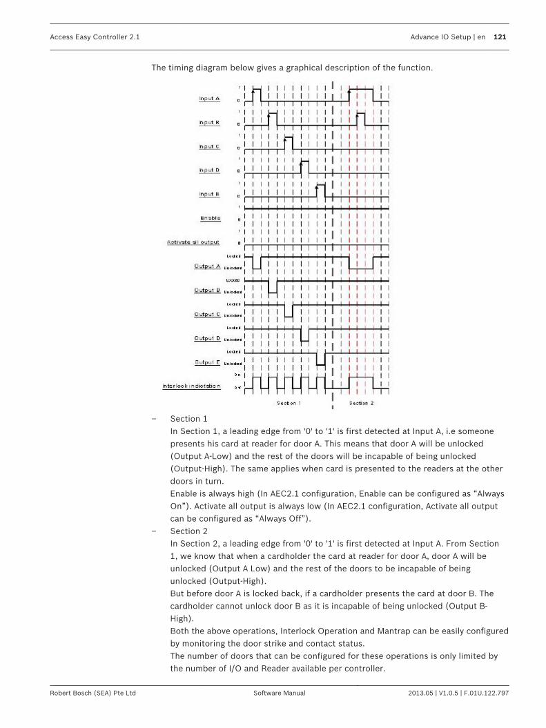
The timing diagram below gives a graphical description of the function.
– Section 1In Section 1, a leading edge from '0' to '1' is first detected at Input A, i.e someonepresents his card at reader for door A. This means that door A will be unlocked(Output A-Low) and the rest of the doors will be incapable of being unlocked(Output-High). The same applies when card is presented to the readers at the otherdoors in turn.Enable is always high (In AEC2.1 configuration, Enable can be configured as “AlwaysOn”). Activate all output is always low (In AEC2.1 configuration, Activate all outputcan be configured as “Always Off”).
– Section 2In Section 2, a leading edge from '0' to '1' is first detected at Input A. From Section1, we know that when a cardholder the card at reader for door A, door A will beunlocked (Output A Low) and the rest of the doors to be incapable of beingunlocked (Output-High).But before door A is locked back, if a cardholder presents the card at door B. Thecardholder cannot unlock door B as it is incapable of being unlocked (Output B-High).Both the above operations, Interlock Operation and Mantrap can be easily configuredby monitoring the door strike and contact status.The number of doors that can be configured for these operations is only limited bythe number of I/O and Reader available per controller.
Access Easy Controller 2.1 Advance IO Setup | en 121
Robert Bosch (SEA) Pte Ltd Software Manual 2013.05 | V1.0.5 | F.01U.122.797

Up-Down CounterThis function enables the tracking of the number of card holder/event and is able to triggeroutput or control based on the maximum configuration limit.
Up Count InputOutput>0
Reset
Down Count Input
Output>=Max
Input/Output Description
Up count Input Increment the counter when a low to high edge is detected.
Down count Input Decrement the counter when a low to high edge is detected.
Reset Reset the counter to zero when a low to high edge is detected.
Output > 0 Set high when the counter is not zero, and set low when thecounter is zero.
Output >= Max Set high when the counter is greater than or equal to themaximum limit, else set low.
The timing diagram below gives a graphical description of the function.
In the timing diagram, the basic operation of the function is outlined below: -
13.8
122 en | Advance IO Setup Access Easy Controller 2.1
2013.05 | V1.0.5 | F.01U.122.797 Software Manual Robert Bosch (SEA) Pte Ltd

Max Limit = 5 and Pre-Load = 0With the 2 defined parameters, the Output>=Max will be drivenhigh on the 5th pulse on the Up Count input. However, the Output>0 is driven high on the firstpulse. A Reset pulse clears both outputs to zero. Max Limit = 10 and Pre-Load = 5With a Pre-Load of 5 count, the Output>0 is driven high. ThisOutput>0 will be cleared on the 5th pulse on the Down Count input. A pulse on the Up Count input drives the Output>0 high again and the Output>=Max will bedriven high on the 10th pulse.
Exit DoorThis function is mainly used to monitor and control emergency exit doors.
Request to Exit
(Toggle)Door Strike
Lock/Unlock Door
Door Contact
(Level)Door Forced Open
Door Held Open
On
Off
On
Off
Input/Output Description
Request-to-Exit (Toggle) This input is edge triggered from '0' to '1' (leading edge) &toggling. It activates the Door Strike output for a period of theDoor Strike Duration when a leading edge is detected.
Door Contact (Level) This input is edge triggered from '0' to '1' (leading edge). Itactivates the Door Forced Open output when a leading edge isdetected and a period of the Door Forced Open Alarm DelayDuration has passed.
Lock/Unlock Door Permanently locks/unlocks the door when activated.
Door Strike Driven to high for a period of Door Strike Duration when aleading edge is detected at Request-to-Exit.
Door Forced Open Driven to high for the duration when Door Contact is high whena leading edge is detected at Door Contact and the Door ForcedOpen Alarm Delay Duration has lapsed.
Door Held Open Driven to high when the Door Strike Duration is over andsubsequently, the Door Open Duration is over.
The timing diagram below gives a graphical description of the function
13.9
Access Easy Controller 2.1 Advance IO Setup | en 123
Robert Bosch (SEA) Pte Ltd Software Manual 2013.05 | V1.0.5 | F.01U.122.797

In the timing diagram, it is divided into 4 sections. The basic operation of each section isoutlined below: - – Section 1
In Section 1, a leading edge from '0' to '1' is detected at Request-to-Exit. This causes theDoor strike to be driven high for a duration of t1, the Door Strike Duration.
– Section 2In Section 2, a leading edge is first detected at Lock/Unlock Door. This causes the Doorstrike to be driven high for the duration when the Lock/Unlock Door is triggered. Sincethe Door Strike is already at state high, meaning it is de-energized, when a leading edge isdetected at Request-to-Exit, there is no difference in Door Strike.
– Section 3In Section 3, a leading edge is detected at Door Contact. However there is a Door ForcedOpen Alarm Delay Duration of period t3. Hence the Door Forced Open is driven high onlyafter the Door Forced Open Alarm Delay Duration has passed and remains high until theDoor Contact is triggered low. The Door Forced Open Alarm Delay Duration is to ensurethat the alarm is genuine and not caused by noise or interference.
– Section 4In Section 4, a leading edge is detected at Door Contact. However the signal lasts for aperiod less than the Door Forced Open Alarm Delay Duration of period t3. Therefore theDoor Forced Open output is not activated. This is because the signal detected could bedue to noise or interference.
One ShotThis function is similar to Feed Through except it is used when the output of a function blockis triggered for a predefined duration when input state is high.
13.10
124 en | Advance IO Setup Access Easy Controller 2.1
2013.05 | V1.0.5 | F.01U.122.797 Software Manual Robert Bosch (SEA) Pte Ltd

This function will enable any type of output such as physical output, link or reader control tofollow the input such as physical input, physical output, link, criteria or schedule.
Input Output
Input/Output Description
Input source(Toggle) The input will be linked to the output directly.It is edge triggeredfrom '0' to '1' (leading edge).
Output The output is a direct link of the input.
Intrusion FunctionThis function is used to integrate a 3rd party intrusion system to AEC2.1 using standard input/output from the AEC.
Input A Output
Input B
1
1
0
0
Ready to Arm
Alarm Zone(Activated based on
Card)
Ready to Arm (3rd Party Alarm Zone Output
Ready to Arm Armed Armed
Ready to Arm Disarmed Disarmed
Not Ready to Arm Armed Disarmed
Not Ready to Arm Disarmed Disarmed
The triggering function for a signal to Arm/Disarm the IDS panel is determined by the criteriathat are set. When the IDS Status shows ‘ready’, and the criteria set is fulfilled, the AECsystem will Lock/Unlock a 4R8IO Output. This change in the status of the 4R8IO Output willbe used as a signal to Arm/Disarm the IDS panel.
13.11
Access Easy Controller 2.1 Advance IO Setup | en 125
Robert Bosch (SEA) Pte Ltd Software Manual 2013.05 | V1.0.5 | F.01U.122.797
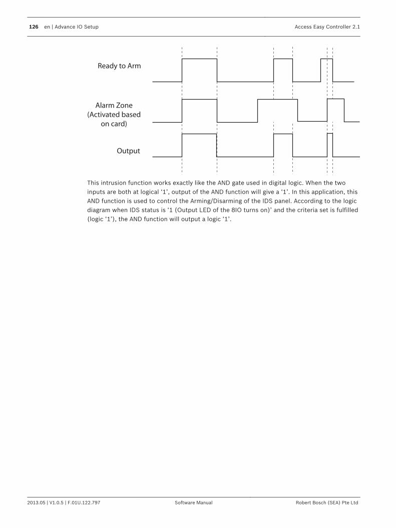
Ready to Arm
Alarm Zone
(Activated based
on card)
Output
This intrusion function works exactly like the AND gate used in digital logic. When the twoinputs are both at logical ‘1’, output of the AND function will give a ‘1’. In this application, thisAND function is used to control the Arming/Disarming of the IDS panel. According to the logicdiagram when IDS status is ‘1 (Output LED of the 8IO turns on)’ and the criteria set is fulfilled(logic ‘1’), the AND function will output a logic ‘1’.
126 en | Advance IO Setup Access Easy Controller 2.1
2013.05 | V1.0.5 | F.01U.122.797 Software Manual Robert Bosch (SEA) Pte Ltd

Input StateThis chapter explains the steps to configure the input and output points.
Input Point ConfigurationThe state of each Input point must be closed for the AEC2.1 to treat it as normal state.However, there are some devices whose normal state is open thus, representing an activated/alarm state.When such devices are connected to these Input points, without inverting an inputto the normal state, it would cause unexpected or false alarm. In simple term, thisconfiguration allows you to invert the logical state of the input that is seen in the AEC2.1 thusallowing such devices to be used. AEC2.1 allows all the Input Points to be inverted exceptthose assigned to Exit Readers and Arm/Disarm Readers.
To Activate Input Point ConfigurationClick the link Configuration > Input State to access the input point configuration.The screenbelow shows the input state page.
To Select Input Point ConfigurationSupport Configurable Non-Supervised/ Supervised for All Input PointsThe input state menu supports configurable Non-Supervised/Supervised for All Input Pointsand Readers. This provides the system installer to have the flexibility to configure any input inthe panel to be in any monitoring requirement. Each input is programmable for 2 state or 4 state supervised– 2 state non supervised or supervised is used to monitor normal conditions– 4 state supervised is used to monitor normal, open and short conditions. Example, a short condition is shorting the input wiring and open condition is a cut wire. Thepanel will report fault in open or short condition only when the input is configured as 4 StateSupervised monitoring. Follow the steps below to configure the input points.
14
14.1
14.1.1
14.1.2
Access Easy Controller 2.1 Input State | en 127
Robert Bosch (SEA) Pte Ltd Software Manual 2013.05 | V1.0.5 | F.01U.122.797

1. The screen below shows the Reader input state screen. To change the supervised modefor each input, select the radio button representing each mode.
2.Click the save button to save the settings.
Alarm Zone DescriptionThe Alarm Zone Description allows you to change the description for each Alarm Zone todescribe the alarm zone location more clearly. Click the link Configuration > Alarm Zone to access the Alarm Zone Description page. Thescreen below shows the alarm description page.
1. To change the Alarm Zone Description for each Alarm Zone, delete the default descriptionfrom each Alarm Zone and enter the new description accordingly.
2.After making the changes, click the save button to save the settings.
14.2
128 en | Input State Access Easy Controller 2.1
2013.05 | V1.0.5 | F.01U.122.797 Software Manual Robert Bosch (SEA) Pte Ltd

CriteriaCriteria are some of the conditions or limitations that are imposed on the input to thefunctional block. Conditions or limitations can be imposed on the devices, cardholders orevents. You can choose to include items to trigger the output or omit items so that it will nottrigger the output of the functional block. A table listing the choice that can be selected undereach item is shown below.
Criteria Configuration Choice that can be selected
Devices – All readers, input & output points– All readers only– All input points only– All output points only– Selected devices only– Omit these selected devices only
Cardholders – All cardholders– Selected cardholders only– Omit these selected cardholders only– Selected Access Group only
Events – All events– Selected events only– Omit these selected events only
Time – Based on Time
1. Click the link Configuration > Criteria to access the criteria page.2.
Click the button to add a new criteria. The screen below appears.
3. Enter a Description for the criteria in the Description field.4. The criteria main page consists of four function tabs namely Configuration, Cardholder,
Events and Time. Click the tab Configuration.5. In the Configuration > Criteria settings select the appropriate radio button.
Configuration SettingClick the Configuration tab in the criteria page to access the criteria setting details. In theconfiguration page, select the appropriate radio button. When Selected devices only is chosen
15
15.1
Access Easy Controller 2.1 Criteria | en 129
Robert Bosch (SEA) Pte Ltd Software Manual 2013.05 | V1.0.5 | F.01U.122.797
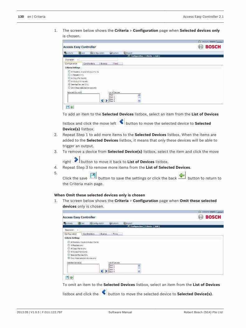
1. The screen below shows the Criteria > Configuration page when Selected devices onlyis chosen.
To add an item to the Selected Devices listbox, select an item from the List of Devices
listbox and click the move left button to move the selected device to SelectedDevice(s) listbox.
2. Repeat Step 1 to add more items to the Selected Devices listbox. When the items areadded to the Selected Devices listbox, it means that only these devices will be able totrigger an output.
3. To remove a device from Selected Device(s) listbox, select the item and click the move
right button to move it back to List of Devices listbox.4. Repeat Step 3 to remove more items from the List of Selected Devices.5.
Click the save button to save the settings or click the back button to return tothe Criteria main page.
When Omit these selected devices only is chosen1. The screen below shows the Criteria > Configuration page when Omit these selected
devices only is chosen.
To omit an item to the Selected Devices listbox, select an item from the List of Devices
listbox and click the button to move the selected device to Selected Device(s).
130 en | Criteria Access Easy Controller 2.1
2013.05 | V1.0.5 | F.01U.122.797 Software Manual Robert Bosch (SEA) Pte Ltd
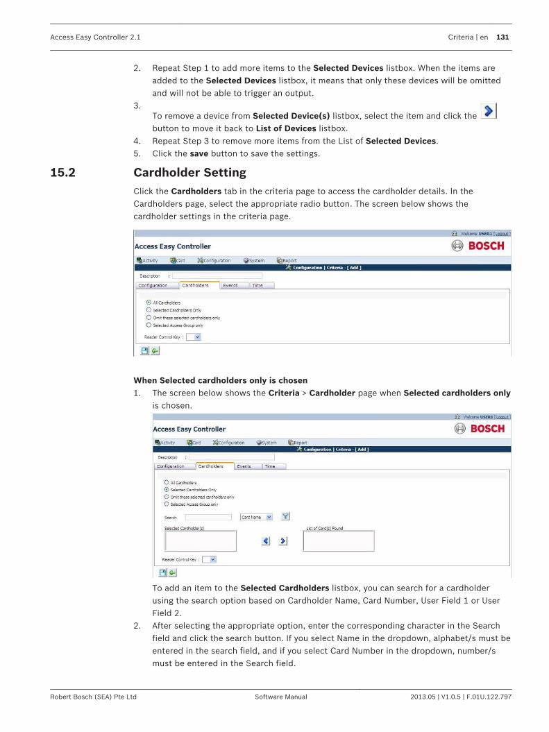
2. Repeat Step 1 to add more items to the Selected Devices listbox. When the items areadded to the Selected Devices listbox, it means that only these devices will be omittedand will not be able to trigger an output.
3.To remove a device from Selected Device(s) listbox, select the item and click the button to move it back to List of Devices listbox.
4. Repeat Step 3 to remove more items from the List of Selected Devices.5. Click the save button to save the settings.
Cardholder SettingClick the Cardholders tab in the criteria page to access the cardholder details. In theCardholders page, select the appropriate radio button. The screen below shows thecardholder settings in the criteria page.
When Selected cardholders only is chosen1. The screen below shows the Criteria > Cardholder page when Selected cardholders only
is chosen.
To add an item to the Selected Cardholders listbox, you can search for a cardholderusing the search option based on Cardholder Name, Card Number, User Field 1 or UserField 2.
2. After selecting the appropriate option, enter the corresponding character in the Searchfield and click the search button. If you select Name in the dropdown, alphabet/s must beentered in the search field, and if you select Card Number in the dropdown, number/smust be entered in the Search field.
15.2
Access Easy Controller 2.1 Criteria | en 131
Robert Bosch (SEA) Pte Ltd Software Manual 2013.05 | V1.0.5 | F.01U.122.797

3.Select a cardholder detail and click the button. The selected detail will appear in theSelected Cardholders listbox.
4. Repeat Step 1, 2 and 3 to add more items to the Selected Cardholders list. When theitems are added to the Selected Cardholders list, it means that only these cardholderswill trigger an output.
5. To remove an item from the Selected Cardholders list, select the item on the list and
click the button.6. Repeat Step 5 to remove more items from the List of Selected Cardholders When Omit these selected cardholders only is chosen1. The screen below shows the Criteria > Cardholder page when Omit these selected
cardholders only is chosen.
To add an item to the Selected Cardholders listbox, you can search for a cardholderusing the Search Option based on Cardholder Name, Card Number, User Field 1 or UserField 2.
2. After selecting the appropriate option, enter the corresponding character in the Searchfield and click the search button. If you select Name in the dropdown, alphabet/s must beentered in the search field, and if you select Card Number in the dropdown, number/smust be entered in the Search field.
3.Select a cardholder detail and click the move left button.
4. Repeat Step 1, 2 and 3 to add more items to the Selected Cardholders list. When theitems are added to the Selected Cardholders list, it means that these cardholders will beomitted and will not be able to trigger an output.
5. To remove an item from the Selected Cardholders list, select the item on the list and
click move right button.6. Repeat Step 5 to remove more items from the List of Selected Cardholders. When Selected Access Group only is chosen
132 en | Criteria Access Easy Controller 2.1
2013.05 | V1.0.5 | F.01U.122.797 Software Manual Robert Bosch (SEA) Pte Ltd
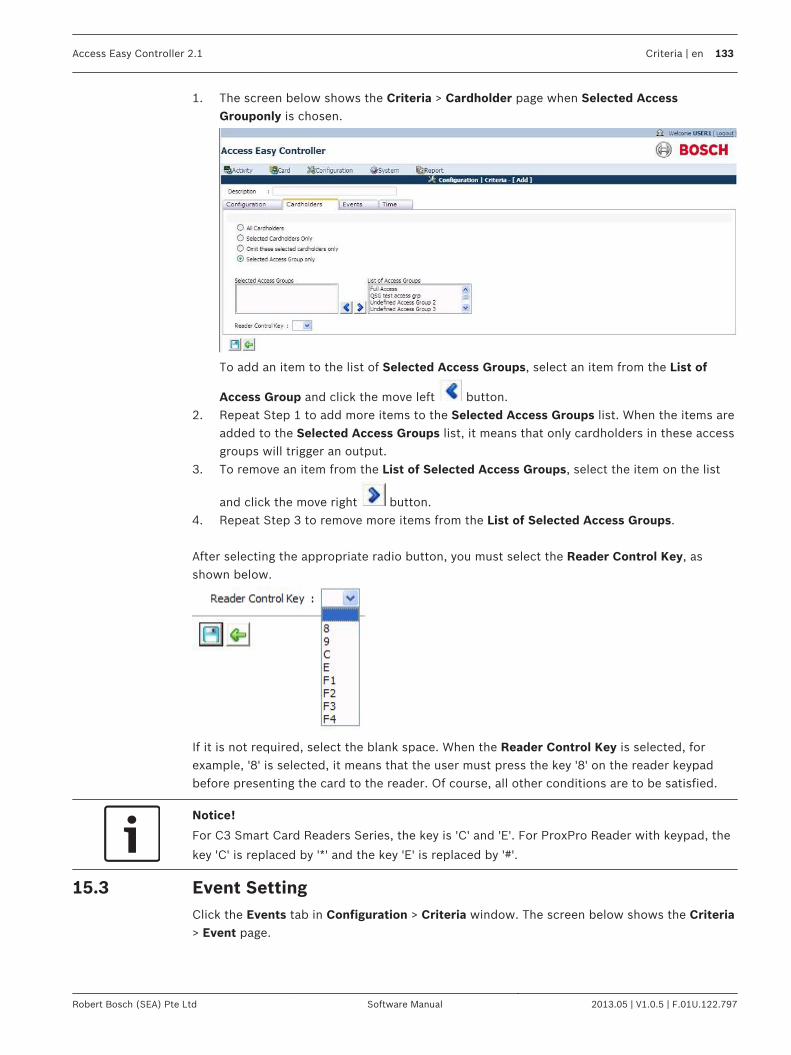
1. The screen below shows the Criteria > Cardholder page when Selected AccessGrouponly is chosen.
To add an item to the list of Selected Access Groups, select an item from the List of
Access Group and click the move left button.2. Repeat Step 1 to add more items to the Selected Access Groups list. When the items are
added to the Selected Access Groups list, it means that only cardholders in these accessgroups will trigger an output.
3. To remove an item from the List of Selected Access Groups, select the item on the list
and click the move right button.4. Repeat Step 3 to remove more items from the List of Selected Access Groups. After selecting the appropriate radio button, you must select the Reader Control Key, asshown below.
If it is not required, select the blank space. When the Reader Control Key is selected, forexample, '8' is selected, it means that the user must press the key '8' on the reader keypadbefore presenting the card to the reader. Of course, all other conditions are to be satisfied.
Notice!
For C3 Smart Card Readers Series, the key is 'C' and 'E'. For ProxPro Reader with keypad, the
key 'C' is replaced by '*' and the key 'E' is replaced by '#'.
Event SettingClick the Events tab in Configuration > Criteria window. The screen below shows the Criteria> Event page.
15.3
Access Easy Controller 2.1 Criteria | en 133
Robert Bosch (SEA) Pte Ltd Software Manual 2013.05 | V1.0.5 | F.01U.122.797

In the Events page, select the appropriate radio button. When Selected events only is chosen1. The screen below shows the Criteria > Events page when Selected events only is
chosen.
To add an item to the Selected Events list, select an item from the List of Events listbox
and click the button.2. Repeat Step 1 to add more items to the List of Selected Events. When the items are
added to the List of Selected Events, it means that only these events will trigger anoutput.
3. To remove an item from the List of Selected Events, select the item on the list and click
the button.4. Repeat Step 3 to remove more items from the List of Selected Events. When Omit these selected events only is chosen
134 en | Criteria Access Easy Controller 2.1
2013.05 | V1.0.5 | F.01U.122.797 Software Manual Robert Bosch (SEA) Pte Ltd

1. The screen below shows the Criteria > Events page when Omit these selected eventsonly is chosen.
To add an item to the List of Selected Events, select an item from the List of events
listbox and click the button.2. Repeat Step 1 to add more items to the List of Selected Events. When the items are
added to the List of Selected Events, it means that only these events will be omitted andwill not be able to trigger an output.
3. To remove an item from the List of Selected Events, select the item on the list and click
the button.4. Repeat Step 3 to remove more items from the List of Selected Events.
Time Setting1. Click the Time tab in Configuration > Criteria window.The screen below shows the
Criteria > Time page.
2. Select a schedule from the Based on Schedule dropdown. When a schedule is selected itmeans the events triggered during the selected schedule will trigger an output.
15.4
Access Easy Controller 2.1 Criteria | en 135
Robert Bosch (SEA) Pte Ltd Software Manual 2013.05 | V1.0.5 | F.01U.122.797

Schedules and HolidaysThis chapter explains the steps to set a schedule and holiday.
SchedulesSchedule defines 4 sets of start and end time for seven days a week. Regular and specialholidays have a separate 4 sets of time intervals. There are 255 programmable Schedules.Schedules can be used in the following way: – Schedules are allocated to Card Readers for Access Groupings. Schedules are used to set
a specific time when the cardholders can access specific readers or set a specific timewhen the cardholders need to enter PIN to access specific readers.
– Schedules are allocated to the Card Readers to activate or deactivate readers at specifiedtime. Schedules are used to define the time intervals to Arm/Disarm Alarm Zone.
– Schedules are used to define the time intervals for triggering the Output Points. Forexample, this is used for scheduled triggering of lighting utility for an area.
– Schedules are used for enabling the video verification function.The implementation of Schedule makes the system very flexible as its behavior can beprogrammed to be different for different time of a day, different days, or even during Holidays.A good example is, cardholders have to enter PIN only after office hours. 1. Click the link Configuration > Schedules to access the schedule page. The screen below
shows the schedule main page.
2.Click the button to add a new schedule. The screen below appears.
3. Enter a description for the schedule in the Description field. This is the name of theschedule that appears when a schedule is called.
16
16.1
136 en | Schedules and Holidays Access Easy Controller 2.1
2013.05 | V1.0.5 | F.01U.122.797 Software Manual Robert Bosch (SEA) Pte Ltd

4. Click and drag the cursor along the day and time chart to select the time. The screenappears as shown below.
The schedule info window is shown below.The selected day checkbox will be disabled inthe schedule info window.The schedule info will display the time scheduled by you in the date and time chart.
5. You can also edit the time by using the start and end time dropdown list.6. To copy the same time setting to other days use the insert info selection checkbox.7.
Click the save button to save the settings. Click the back button to return to
the schedule page without applying the changes or click the delete button to deletethe settings and return to the schedule page.
Access Easy Controller 2.1 Schedules and Holidays | en 137
Robert Bosch (SEA) Pte Ltd Software Manual 2013.05 | V1.0.5 | F.01U.122.797

8. After saving the settings the time of operation is copied to the selected days and asample schedule window is shown below for reference.
9.Click the save button to save the schedule. Click the back button to cancel thechanges and return to the schedule main page.
In the Schedule main page you can edit or delete a schedule. Click the edit button toedit the settings of the existing schedule. The edit schedule page is same as the add schedulepage.
Click the delete button to delete an existing schedule.
System Behavior when Using ScheduleThe diagram below provides a graphical representation of the system's behavior when aSchedule is used on the various functions.
16.1.1
138 en | Schedules and Holidays Access Easy Controller 2.1
2013.05 | V1.0.5 | F.01U.122.797 Software Manual Robert Bosch (SEA) Pte Ltd
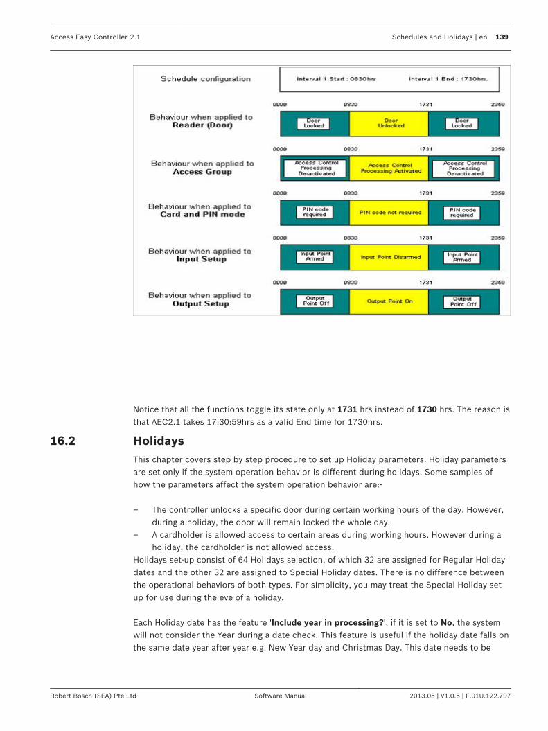
Notice that all the functions toggle its state only at 1731 hrs instead of 1730 hrs. The reason isthat AEC2.1 takes 17:30:59hrs as a valid End time for 1730hrs.
HolidaysThis chapter covers step by step procedure to set up Holiday parameters. Holiday parametersare set only if the system operation behavior is different during holidays. Some samples ofhow the parameters affect the system operation behavior are:- – The controller unlocks a specific door during certain working hours of the day. However,
during a holiday, the door will remain locked the whole day.– A cardholder is allowed access to certain areas during working hours. However during a
holiday, the cardholder is not allowed access.Holidays set-up consist of 64 Holidays selection, of which 32 are assigned for Regular Holidaydates and the other 32 are assigned to Special Holiday dates. There is no difference betweenthe operational behaviors of both types. For simplicity, you may treat the Special Holiday setup for use during the eve of a holiday. Each Holiday date has the feature 'Include year in processing?', if it is set to No, the systemwill not consider the Year during a date check. This feature is useful if the holiday date falls onthe same date year after year e.g. New Year day and Christmas Day. This date needs to be
16.2
Access Easy Controller 2.1 Schedules and Holidays | en 139
Robert Bosch (SEA) Pte Ltd Software Manual 2013.05 | V1.0.5 | F.01U.122.797

defined once and the holiday date is set on the same date every year. For those holiday datesthat vary from year to year the date has to be updated at the beginning of the year, and'Include year in processing?' must be set to Yes. You can use this feature to ease the updating of holiday dates every year by allocating thefixed holiday dates to regular holiday and the variable holiday dates to special holidays. In thisway, you just need to update the variable holiday dates i.e. special holidays and skip the fixedholiday dates i.e. regular holidays at the beginning of the year. 1. Click the link Configuration > Holidays to access the holiday page. The screen below
appears.
2.In the Holiday main page select the tab regular holiday and click the button to add anew holiday date. The screen below appears.
3. Enter a description for the holiday in the Description field.4. Click the calendar picker to select the holiday date.5. Click the radio button No besides Include year in processing? if the holiday date is fixed,
else click Yes.6. Click the save button to save the entries. Click the back button to cancel the entries and
return to the holiday main page.7. Repeat steps 2 to 7 for configuring special holidays also.
In the Holiday main page you can edit or delete a holiday. Click the edit button to editthe settings of the existing holiday. The edit holiday page is same as the add holiday page.
Click the delete button to delete an existing holiday.
140 en | Schedules and Holidays Access Easy Controller 2.1
2013.05 | V1.0.5 | F.01U.122.797 Software Manual Robert Bosch (SEA) Pte Ltd

UsersThis chapter explains the steps to define different access controls to users.
User AdministrationEach user is assigned access rights to access and carry out programming of certain or allfunctions of the AEC2.1. The User administration menu item allows the System Administrator to define different accesscontrol to users, by selecting whether a particular user can have View and/or Edit/Controlrights to programming certain functions. The system can assign 24 users. By default, user1 is defined as the Super-user having accessto all the AEC2.1 features. The user id and password of the super user can be changed but thefunction rights of the super user cannot be modified or disabled. The default super-user can define the access rights (View and/or Edit/Control) of theremaining 24 users, up to the level equivalent to the Super-user. The AEC2.1 software will not display the access button of the functions for the users who donot have the Supervisory Access Level rights login, implying that changes or settings madecannot be saved.
To Enter User Information1. Click the link System > User Administration to access the user details page. the screen
below shows the User Administration home page. The user administration main pageconsists of two tabs namely the User and User Profile.
2. Select the User tab to add or modify User information.3.
Click the button to add a new user to the AEC2.1 system. The screen below showsthe add user page.
4. Enter a username in the Username field.
17
17.1
17.1.1
Access Easy Controller 2.1 Users | en 141
Robert Bosch (SEA) Pte Ltd Software Manual 2013.05 | V1.0.5 | F.01U.122.797
5. Enter the password in the Password field. The password is limited to 50 alphanumericalcharacters including punctuation marks.
6. Re-enter the password in the confirm field. The password entered in the Password fieldand Confirm Password field must match else a error pops up indicating wrong passwordentered.
7. Select User Profile dropdown list. The user profile dropdown lists the user profilescreated in the user profile page. This lists the pre defined access rights for the user. Auser can be assigned to a profile by selecting the profile from the dropdown. This reducesthe time in creating individual user access rights.
8. Select the option for Default Login page from the drop down list. This action will take theuser to the particular page selected by the user.
9. Select Video Access options according to the location of the camera. If the camera is atremote location, then select Internet option else select Intranet.
10. Check or uncheck the Do not prompt to show current version info after log-in. checkboxaccordingly. If you want the system to check the current AEC version and availableupdates each time you log into the system, do not select this option. Selecting it willdisable the check for updates.
11.Click the save button to save the setting. Click the back button to cancel thesettings and to return to the user main page.
Notice!
The username and Password are case-sensitive. For security reason, every character entered
in the Password field is represented by a dot.
In the User main page you can edit or delete a user configuration. Click the edit buttonto edit the settings of the existing user. The edit user page is same as the add user page.
Click the delete button to delete an existing user configuration.
To Select User ProfileRefer to the corresponding chapters to understand the various menu items before assigningthe access rights to the user. The FTP (File Transfer) title refers to the use of the separate AEC2.1 Utility program called theDatabase Converter. Refer to AEC2.1 Utility Programs Manual for more details. User profile page consists of the option View and Edit/Control.
ViewIf checked, implies the user has rights to view the contents of that menu item.
Edit/ControlIf checked, implies the user has the right to access and edit the setting within the menu item
17.1.2
142 en | Users Access Easy Controller 2.1
2013.05 | V1.0.5 | F.01U.122.797 Software Manual Robert Bosch (SEA) Pte Ltd

1. Click the link System > User Administration to access the user page. In the useradministration page select the tab user profile to edit the access rights of the user. Thescreen below shows the User Profile page.
2.In the user profile main page click the button to add a new profile. The screen belowshows the add user profile page.
3. Enter a description for the user profile in the Description field. This description ispresented in the user profile dropdown list in the user information page.
4. Select the desired checkbox for the user to have access to view and/or Edit/Control themenu items. To de-select access rights, click the check box again.
For example in the Reports heading, you can grant access to the user to save the reportin a csv format. This option is available for the activity and audit log reports. For otherreports you can only view the report preview.
Access Easy Controller 2.1 Users | en 143
Robert Bosch (SEA) Pte Ltd Software Manual 2013.05 | V1.0.5 | F.01U.122.797
5.Click the save button to save the settings. Click the back button to cancel thesettings and return to the user profile main page.
In the User Profile main page you can edit or delete a user profile. Click the edit buttonto edit the settings of the existing user profile. The edit user profile page is same as the adduser profile page.
Click the delete button to delete an existing user profile.
144 en | Users Access Easy Controller 2.1
2013.05 | V1.0.5 | F.01U.122.797 Software Manual Robert Bosch (SEA) Pte Ltd
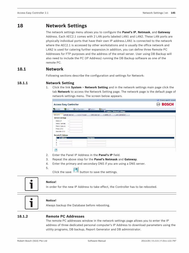
Network SettingsThe network settings menu allows you to configure the Panel's IP, Netmask, and GatewayAddress. Each AEC2.1 comes with 2 LAN ports labeled LAN1 and LAN2. These LAN ports arephysically individual ports that have their own IP address.LAN1 is connected to the networkwhere the AEC2.1 is accessed by other workstations and is usually the office network andLAN2 is used for catering further expansion.In addition, you can define three Remote PCAddresses for FTP purposes and the address of the email server. User using DB Backup willalso need to include the PC (IP Address) running the DB Backup software as one of theremote PC.
NetworkFollowing sections describe the configuration and settings for Network:
Network Setting1. Click the link System > Network Setting and in the network settings main page click the
tab Network to access the Network Setting page. The network page is the default page ofnetwork settings menu. The screen below appears.
2. Enter the Panel IP Address in the Panel's IP field.3. Repeat the above step for the Panel's Netmask and Gateway.4. Enter the primary and secondary DNS if you are using a DNS server.5.
Click the save button to save the settings.
Notice!
In order for the new IP Address to take effect, the Controller has to be rebooted.
Notice!
Always backup the Database before rebooting.
Remote PC AddressesThe remote PC addresses window in the network settings page allows you to enter the IPaddress of three dedicated personal computer's IP Address to download parameters using theutility programs, DB backup, Report Generator and DB administrator.
18
18.1
18.1.1
18.1.2
Access Easy Controller 2.1 Network Settings | en 145
Robert Bosch (SEA) Pte Ltd Software Manual 2013.05 | V1.0.5 | F.01U.122.797

Notice!
For usage of the utility programs, refer to the AEC2.1 Utility Programs Manual.
To edit Remote PC Addresses1. Enter the IP Address's of the remote PC in the IP address field.2. Enter the PC name as a complete word, with no spacing in the hostname field.3.
Click the save button to save the settings. The screen below shows an example ofthe network settings page.
Email Server Setup InformationThis section allows you to define the IP address of the Outgoing Mail (SMTP) server, the SMTPport to use and the AEC2.1 Email Address/Name. Click the link System > Network settingsand in the network settings main page click the Email Server tab to access the Email serverinformation page. The screen below shows the Email server page.
The Outgoing Mail (SMTP) Server defines the server that provides your email facilities and theAEC2.1 Email Address/Name in the reply address for emails sent by the AEC2.1 that is, thename address that is to appear in the 'sent to' field of the dispatched email. Check the EmailService Logon Information icon for authentication. The user can key in the user name andpassword of upto 16 characters.
To Configure the Email Server Setup Information1. Enter the Outgoing Mail Server IP address in the Outgoing Mail (SMTP) Server field.
18.2
18.2.1
146 en | Network Settings Access Easy Controller 2.1
2013.05 | V1.0.5 | F.01U.122.797 Software Manual Robert Bosch (SEA) Pte Ltd

2. Select the Outgoing Mail (SMTP) Server Port from the drop down list. The defaultnumber (25) is the commonly used port number. We suggest you skip this field unlessyour port is different.
3. If you have chosen a custom port number for the Outgoing Mail (SMTP) Server, you canselect the Encrypted Connection from the drop down list. Otherwise, the defaultEncrypted Connection is based on the selected Outgoing Mail (SMTP) Server Port.
4. Enter the AEC2.1 Address/Name as a complete word, with no spacing in between. Youcan use the underscore ( _ ) to denote spacing. The Address/Name specified in this fieldwill be used together with the Domain name to form the email address of the AEC2.1.Referring to the diagram and with the Domain name "bosch.com.sg", the email address ofAEC2.1 will be [email protected]
5.Click the save button to save the settings.
Dial In IP Setup InformationThis section allows you to configure the Dial In IP that is required for PPP protocol. In order tohave remote access ability using a modem for connection, a temporary IP address has to beissued to the incoming connection. When you dial in from home, using your PC and a modem,the AEC2.1's modem will answer the incoming call and negotiate with the remote modem for asuitable connection protocol and speed. If the process is successful, a temporary IP is issuedto the remote modem and the connection is established. By default, this Dial in IP address isset at 10.1.1.2. It work's fine on most network setup, change the address if you encounterconnection problem. To change this setting, click the link System > Network settings and in the network settingspage click the Dial In tab to access the Dial In Setting page.The screen below shows the DialIn settings page.
To Edit the Dial In IP Settings Information1. Enter the default IP in the Dial In IP field.2. Enter a Username and Password for the user to access the AEC2.1 through a dial In
process.3. Select a number from the dropdown for the number of illegal attempts the user can have
before successfully logging in the system.4. Select a time from the Lockout duration dropdown. This time is the time duration set
between illegal attempts. The time range is between 1 to 255 minutes.5.
Click the save button to save the settings.
18.3
18.3.1
Access Easy Controller 2.1 Network Settings | en 147
Robert Bosch (SEA) Pte Ltd Software Manual 2013.05 | V1.0.5 | F.01U.122.797
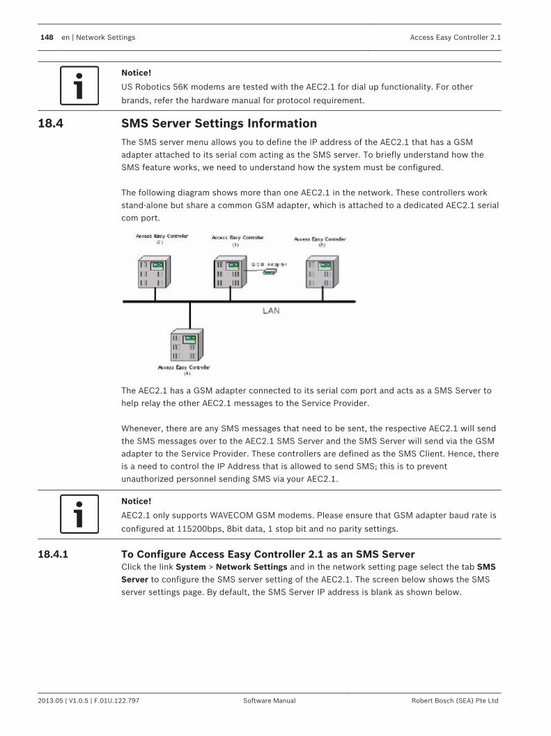
Notice!
US Robotics 56K modems are tested with the AEC2.1 for dial up functionality. For other
brands, refer the hardware manual for protocol requirement.
SMS Server Settings InformationThe SMS server menu allows you to define the IP address of the AEC2.1 that has a GSMadapter attached to its serial com acting as the SMS server. To briefly understand how theSMS feature works, we need to understand how the system must be configured. The following diagram shows more than one AEC2.1 in the network. These controllers workstand-alone but share a common GSM adapter, which is attached to a dedicated AEC2.1 serialcom port.
The AEC2.1 has a GSM adapter connected to its serial com port and acts as a SMS Server tohelp relay the other AEC2.1 messages to the Service Provider. Whenever, there are any SMS messages that need to be sent, the respective AEC2.1 will sendthe SMS messages over to the AEC2.1 SMS Server and the SMS Server will send via the GSMadapter to the Service Provider. These controllers are defined as the SMS Client. Hence, thereis a need to control the IP Address that is allowed to send SMS; this is to preventunauthorized personnel sending SMS via your AEC2.1.
Notice!
AEC2.1 only supports WAVECOM GSM modems. Please ensure that GSM adapter baud rate is
configured at 115200bps, 8bit data, 1 stop bit and no parity settings.
To Configure Access Easy Controller 2.1 as an SMS ServerClick the link System > Network Settings and in the network setting page select the tab SMSServer to configure the SMS server setting of the AEC2.1. The screen below shows the SMSserver settings page. By default, the SMS Server IP address is blank as shown below.
18.4
18.4.1
148 en | Network Settings Access Easy Controller 2.1
2013.05 | V1.0.5 | F.01U.122.797 Software Manual Robert Bosch (SEA) Pte Ltd

If this controller is attached to a GSM adapter, you will need to configure the IP address ofother AEC2.1 that will send SMS message through it. 1. Since this is an SMS Server, select the radio button Yes besides GSM Connected?. The
SMS Server Setting page is shown below:
2. There are up to 10 Remote Controller addresses that you can configure. These addressesare the IP Address of those AEC2.1’s that send SMS messages via the SMS Server. Besure to include the IP address of the AEC 2.1 that is acting as the SMS server or else itwill not be able to send SMS while the rest is able to.
3.Click the save button to save the settings.
AEMC SettingsAccess Easy series come with an Access Easy Master Controller. The master controller enablesyou to connect to up to 20 AEC2.1 through a hub. This will greatly increase the capacity of thewhole system. To differentiate between a stand-alone controller and one that is connected toa master controller, they will be referred as AEC2.1 and Access Easy Master 2 respectively.
18.5
Access Easy Controller 2.1 Network Settings | en 149
Robert Bosch (SEA) Pte Ltd Software Manual 2013.05 | V1.0.5 | F.01U.122.797

LAN ConverterThe LAN Converter tab will ask for the IP address of the LAN Converter. Connecting throughthe LAN converter, the system can be upgraded to 16 interface boards. The default IP addressis 192.168.2.42. If the user is connecting it to the CPU LAN 2 then enter 192.168.2.X, where Xcan be any number except 41 since 192.168.2.41 is the reserved IP address for LAN 2. The LAN converter support requires AEC2.1 firmware upgrade version 2.1.6.0 or later. Pleasecheck our online AEC software upgrade at http://www.boschsecurity.us/en-us/aec.
18.6
150 en | Network Settings Access Easy Controller 2.1
2013.05 | V1.0.5 | F.01U.122.797 Software Manual Robert Bosch (SEA) Pte Ltd
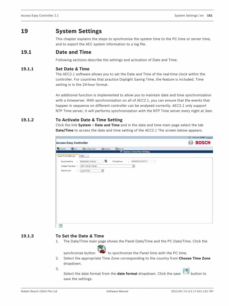
System SettingsThis chapter explains the steps to synchronize the system time to the PC time or server time,and to export the AEC system information to a log file.
Date and TimeFollowing sections describe the settings and activation of Date and Time:
Set Date & TimeThe AEC2.1 software allows you to set the Date and Time of the real-time clock within thecontroller. For countries that practice Daylight Saving Time, the feature is included. Timesetting is in the 24-hour format. An additional function is implemented to allow you to maintain date and time synchronizationwith a timeserver. With synchronization on all of AEC2.1, you can ensure that the events thathappen in sequence on different controller can be analyzed correctly. AEC2.1 only supportNTP Time server, it will performs synchronization with the NTP Time server every night at 3am.
To Activate Date & Time SettingClick the link System > Date and Time and in the date and time main page select the tabDate/Time to access the date and time setting of the AEC2.1 The screen below appears.
To Set the Date & Time1. The Date/Time main page shows the Panel Date/Time and the PC Date/Time. Click the
synchronize button to synchronize the Panel time with the PC time.2. Select the appropriate Time Zone corresponding to the country from Choose Time Zone
dropdown.3.
Select the date format from the date format dropdown. Click the save button tosave the settings.
19
19.1
19.1.1
19.1.2
19.1.3
Access Easy Controller 2.1 System Settings | en 151
Robert Bosch (SEA) Pte Ltd Software Manual 2013.05 | V1.0.5 | F.01U.122.797
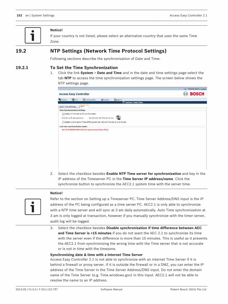
Notice!
If your country is not listed, please select an alternative country that uses the same Time
Zone.
NTP Settings (Network Time Protocol Settings)Following sections describe the synchronisation of Date and Time:
To Set the Time Synchronization1. Click the link System > Date and Time and in the date and time settings page select the
tab NTP to access the time synchronization settings page. The screen below shows theNTP settings page.
2. Select the checkbox besides Enable NTP Time server for synchronization and key in theIP address of the Timeserver PC in the Time Server IP address/name. Click thesynchronize button to synchronize the AEC2.1 system time with the server time.
Notice!
Refer to the section on Setting up a Timeserver PC. Time Server Address/DNS input is the IP
address of the PC being configured as a time server PC. AEC2.1 is only able to synchronize
with a NTP time server and will sync at 3 am daily automatically. Auto Time synchronization at
3 am is only logged at transaction, however if you manually synchronize with the timer server,
audit log will be logged.
3. Select the checkbox besides Disable synchronization if time difference between AECand Time Server is >15 minutes if you do not want the AEC 2.1 to synchronize its timewith the server even if the difference is more than 15 minutes. This is useful as it preventsthe AEC2.1 from synchronizing the wrong time with the Time server that is not accurateor is not in time with the timezone.
Synchronizing date & time with a internet Time ServerAccess Easy Controller 2.1 is not able to synchronize with an internet Time Server if it isbehind a firewall or proxy server. If it is outside the firewall or in a DMZ, you can enter the IPaddress of the Time Server in the Time Server Address/DNS input. Do not enter the domainname of the Time Server (e.g. Time.windows.gov) in this input. AEC2.1 will not be able toresolve the name to an IP address.
19.2
19.2.1
152 en | System Settings Access Easy Controller 2.1
2013.05 | V1.0.5 | F.01U.122.797 Software Manual Robert Bosch (SEA) Pte Ltd

Synchronizing date & time with an intranet Time ServerIt is recommended that AEC2.1 should synchronize its date & time to an intranet (internal)Time Server. Most of the office has an internal Time Server, this Time Server will synchronizeits date & time with an internet (external) Time Server, while all other PCs in the officesynchronize with this intranet Time Server. If the office does not have an intranet Time Server, you can setup any existing PC on thenetwork as a Time Server, hence, the AEC2.1 can synchronize its date and time with this PC.There are numerous freeware available that you could install in this PC to synchronize its dateand time with an external Time Server.
System LogThis function allows you to view the system information at a glance and export all necessaryinformation into a log file. Click the menu System > System Log to access the System Logpage. Overview of the system including product name and version, hardware address, Internetaddress and others are displayed on the System Log page.
Click the System Log button to export all the system information in detail to a log file,which you can open or save to your desktop.
19.3
Access Easy Controller 2.1 System Settings | en 153
Robert Bosch (SEA) Pte Ltd Software Manual 2013.05 | V1.0.5 | F.01U.122.797

Email/SMS ConfigurationThis function allows you to configure the AEC2.1 to send out messages or Lateness Reportusing Simple Mail Transfer Protocol (SMTP) to email addresses. A total of eight groups andeight messages field are available for configuration. Each group has two "Send To" and two"Carbon Copy (Cc)" email addresses. In order for the feature to work, you have to configure the Devices, Cardholders, and Events inan AND operation. To exclude/disable an item(s) from the operation, the option Selected Onlyor Omit Only must be used with nothing selected. While for the Lateness Report, the feature isdisable if no selection is made on any of the day of week (DOW).
Email ConfigurationClick the link Configuration > E-mail/SMS setting in the E-mail/SMS main page select the tabE-mail. In the Email page click the edit button besides any Undefined Email. The screen belowshows the Email configuration page.
This web page allows you to configure the email addresses of the recipients. The AEC2.1 willignore any configurations made for the group if there is no email address in the To field even ifthere is an email address in the Cc field. Each To and Cc must contain one email address,multiple email addresses are not allowed address, hence, will not send out the mail to therecipients.
To Edit the Email Configuration1. Enter a Description for the mail in the Description field. This description is the subject of
the mail.2. In the Email Address Setting window enter the email address in the appropriate field.3. In the Criteria settings window select a criteria from the Criteria Selection dropdown.4. Select a message from the Message dropdown. The messages are configured in the
message tab of the Email/SMS settings page.5.
Click the save button to save the email as a draft copy. Click the back buttonto cancel the settings and return to the main Email/SMS settings page. Click the send
button to send the Email to the recipients in the email address window.
To Send the Email1.
Click the send button to send the email.
20
20.1
20.1.1
20.1.2
154 en | Email/SMS Configuration Access Easy Controller 2.1
2013.05 | V1.0.5 | F.01U.122.797 Software Manual Robert Bosch (SEA) Pte Ltd

2. A successful test message will appear.3. Click the OK button to acknowledge the message.4. If you are unable to send out the email, please check your Email Server Settings again.
In the Email main page you can edit or delete a Email setting. Click the edit button toedit the settings of the existing Email. The edit Email settings page is same as the add Emailsettings page.
Click the delete button to delete an existing Email setting.
SMS ConfigurationClick the link Configuration > Email/SMS setting in the email/SMS main page select the tabSMS. In the SMS main page click the edit button besides any Undefined SMS. The screenbelow shows the SMS configuration page.
1. Enter a description in the Description field.2. In the Mobile Device Setting window enter the mobile numbers to which the SMS has to
be sent. The system can configure up to four mobile devices.3. In the Criteria settings window select a criteria from the Criteria Selection dropdown.4. Select a message from the Message dropdown. The messages are configured in the
message tab of the Email/SMS settings page.5.
Click the save button to save the SMS as a draft copy. Click the back button to
cancel the settings and return to the main Email/SMS settings page. Click the send button to send the SMS to the mobile devices in the Mobile device settings window.
To Send the Email1.
Click the send button to send the SMS.2. A successful test message will appear.3. Click the OK button to acknowledge the message.
In the SMS main page you can edit or delete a SMS. Click the edit button to edit thesettings of the existing SMS. The edit SMS page is same as the add SMS page.
20.2
20.2.1
Access Easy Controller 2.1 Email/SMS Configuration | en 155
Robert Bosch (SEA) Pte Ltd Software Manual 2013.05 | V1.0.5 | F.01U.122.797
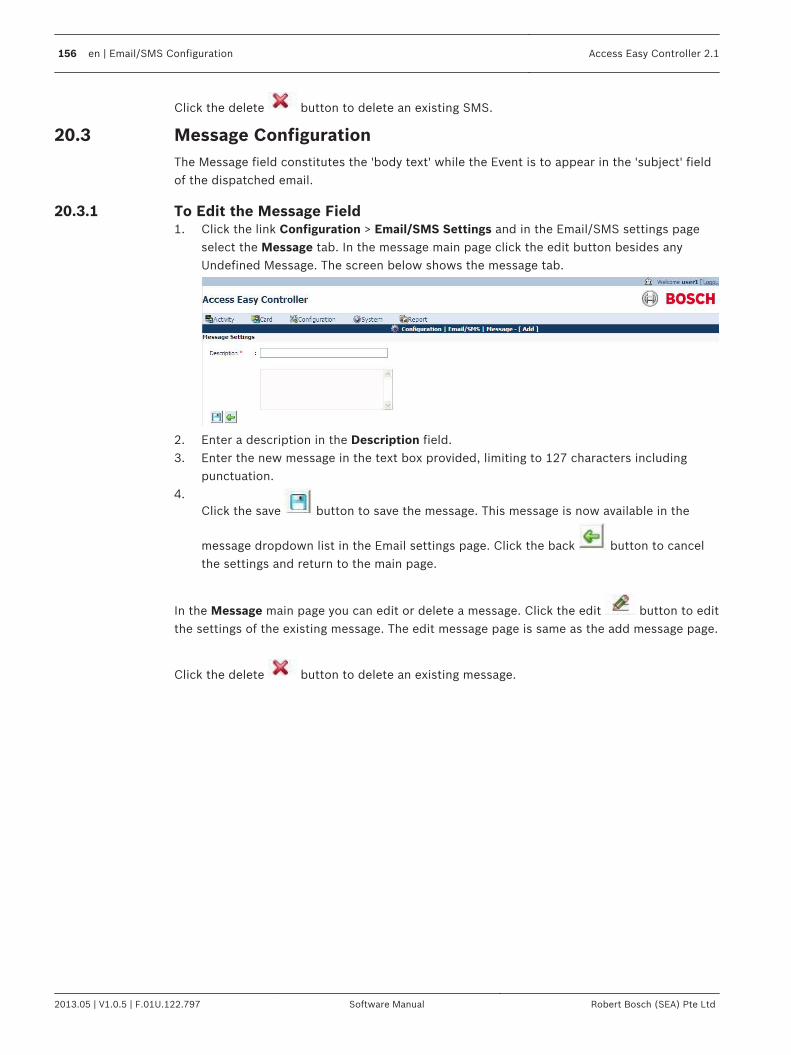
Click the delete button to delete an existing SMS.
Message ConfigurationThe Message field constitutes the 'body text' while the Event is to appear in the 'subject' fieldof the dispatched email.
To Edit the Message Field1. Click the link Configuration > Email/SMS Settings and in the Email/SMS settings page
select the Message tab. In the message main page click the edit button besides anyUndefined Message. The screen below shows the message tab.
2. Enter a description in the Description field.3. Enter the new message in the text box provided, limiting to 127 characters including
punctuation.4.
Click the save button to save the message. This message is now available in the
message dropdown list in the Email settings page. Click the back button to cancelthe settings and return to the main page.
In the Message main page you can edit or delete a message. Click the edit button to editthe settings of the existing message. The edit message page is same as the add message page.
Click the delete button to delete an existing message.
20.3
20.3.1
156 en | Email/SMS Configuration Access Easy Controller 2.1
2013.05 | V1.0.5 | F.01U.122.797 Software Manual Robert Bosch (SEA) Pte Ltd

Advance SettingsThis chapter will guide you through some of the advance features available in AEC2.1.
System MaintenanceFollowing sections describe the various maintanence activities for the panel:
To Activate Reboot PanelSince the AEC2.1's software is residing within its hardware. The Reboot Panel menu itemallows you to reboot the controller after upgrading to the system software or in order to allowchanges made to take effect, especially changes made to Network Setting, such as Panel's IPAddress.
!
Caution!
During a Reboot Panel function, all settings and parameters are taken from the flash
memories. In such a case, it is important that the Database Backup function is carried out
before proceeding to reboot the AEC2.1.
1. Click the link System > Advance Settings and in the advance settings main page selectthe System maintenance tab to reboot the panel.The screen below shows the AdvanceSettings > System Maintenance page.
2.In the maintenance options window click the reboot button to reboot the panel.
3. The message box appears for confirmation. Click the OK button to proceed.4. It takes about two minutes for the process to complete (see NOTICE).
Notice!
During the rebooting process, the AEC2.1 disconnects itself from the computer and the web
page on the computer screen might show an error message or be completely blank. You
should close and re-launch the web browser program. Login to AEC2.1 again after the
process is completed.
Once the AEC2.1 is up and running again, enter the AEC2.1 URL Address and proceed with theLogin.
To Shutdown PanelThe Shutdown Panel function allows you to do a proper shutdown of the controller hardware.This is usually done when controller hardware requires a hardware upgrade or maintenance.
21
21.1
21.1.1
21.1.2
Access Easy Controller 2.1 Advance Settings | en 157
Robert Bosch (SEA) Pte Ltd Software Manual 2013.05 | V1.0.5 | F.01U.122.797

1. Click the link System > Advance Settings and in the advance settings main page selectthe System maintenance tab to shutdown the panel. The screen below shows theAdvance Settings > System Maintenance page
2.In the maintenance options window click the shutdown button to shutdown thepanel.
3. A message box appears for confirmation. Click the OK button to proceed.4. You need to manually switch on the power at the controller once the necessary changes
are done at the controller.
Firmware UpgradeThis function allows AEC2.1 parameters update (database recovery) to the flash to be carriedout merely by a few clicks of the mouse button. You can upgrade the software at AEC.
Notice!
Notice 1: Check with BOSCH SECURITY SYSTEMS or its authorized dealers for the upgrade.
Notice 2: For Database Recovery, you must have the previous parameters setting in encrypted
zipped format (db_tar.gz) in their local hard disk. Refer to the Chapter on Database Backup
for more information.
Notice 3: Before attempting to FTP to the AEC2.1, the Remote PC IP needs to be configured
first in the Network Settings window; else the panel will not allow connection.
Click the link System > Advance Settings and in the advance settings main page select theFirmware upgrade tab to upgrade the firmware. The screen below shows the firmwareupgrade page.
Notice!
The uploading of db_tar.gz will replace all settings and configurations IP address. This action
is irreversible. Make sure that the current settings and configurations are backed up before
commencing.
To Upload Settings and Configurations on the Panel1. Click the browse button to select the file you wish to upload.2.
Click the upload button to upload the file.3. A message box appears for confirmation. Click the OK button to proceed. Once the
process is completed without error, the confirmation message will appear.
21.2
21.2.1
158 en | Advance Settings Access Easy Controller 2.1
2013.05 | V1.0.5 | F.01U.122.797 Software Manual Robert Bosch (SEA) Pte Ltd

4. Reboot the AEC2.1.
5. Click on the browser link AEC2.1 Update to download the latest patch from the Boschintranet.
To Update Panel SoftwareDue to the constant development of the software, the software is designed to allow you toupgrade to the newest version by uploading a file. To differentiate between uploading settingsand configurations, and updating the panel software, the names of the files to upload arefixed. For uploading settings and configurations to the panel, you will upload a db_tar file. Toupdate the panel software, a file named aec_sys will be uploaded.
Notice!
Upload db_tar file for uploading settings and configurations
Upload aec_sys file for updating the panel software
Database BackupThe database menu allows you to choose two options, Backup Database to the Flash Memoryor to the Desktop. Backup Database To Flash Memory allows you to overwrite the database inthe flash memory with the current parameters in the Dynamic Random Access Memory(DRAM). The flash memory acts as a permanent storage just like the computer's hard diskdrive. Every time a Reboot is initiated, the AEC2.1 software will access the flash memory forparameter setting, card database …etc. You are given the option to allow the AEC2.1 to carryout an automatic backup at specific time of the day or to do it manually. The backup database contains the entire database of the AEC2.1 inclusive of activities andlogs. Backup Database To Desktop provides downloading of information which relates to thesetting up of AEC2.1, for example: - Schedules details, Card Readers parameters…etc. It alsoallows you to download the history of the Activity and Attendance in Comma SeparatedVariable (CSV) format.
21.2.2
21.3
Access Easy Controller 2.1 Advance Settings | en 159
Robert Bosch (SEA) Pte Ltd Software Manual 2013.05 | V1.0.5 | F.01U.122.797

Notice!
The database backup functionality is inclusive of activities, events and logs. Please note that
cardholder’s photos or pictures are not included in the backup.
With the downloading, you can save the parameters (in encrypted zipped file) and thetransactions as a backup on your computer hard disk or other external storage media, orfloppy diskette.
!
Warning!
This function requires at least 2-3 minutes to complete the download. During this period,
please do not switch off power to the AEC2.1 or close your Web Browser application. You
MUST wait till the downloading page appears before you could proceed to other page or
close the Web Browser application. If this step is not followed, the backup operation will not
be completed.
To Activate Database BackupClick the link System > Advance Settings and in the advance settings main page select theDatabase Backup tab to access the Database backup page. The screen below shows thedatabase backup page.
To Define Daily Backup Schedule1. Select the appropriate hour and minute from the dropdown list besides Daily backup
schedule.2.
Click the save button to save the backup settings. If you wish to disable this feature, select the "blank" for both Hour and Minute field asillustrated above.
To Backup System Database to DesktopThis process involves two stages, when activated; the software will collect all parametersettings and zipped them up in an encrypted file called db_tar.gz. This encrypted file is onlyrecognizable by the AEC2.1 thus providing security of its contents.
!Warning!
This function required at least 2-3 minutes to complete. During this period, please do not
switch off power to either the computer or the AEC2.1.
21.3.1
21.3.2
21.3.3
160 en | Advance Settings Access Easy Controller 2.1
2013.05 | V1.0.5 | F.01U.122.797 Software Manual Robert Bosch (SEA) Pte Ltd
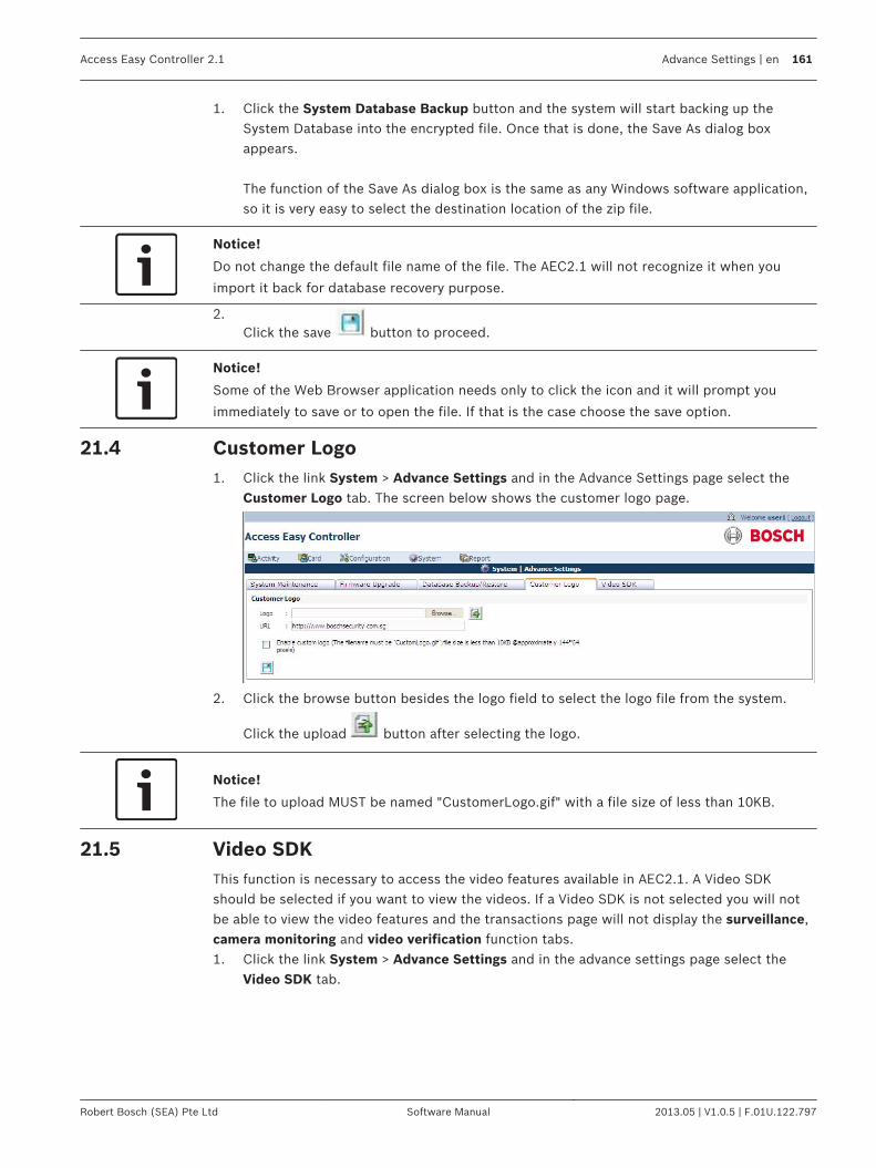
1. Click the System Database Backup button and the system will start backing up theSystem Database into the encrypted file. Once that is done, the Save As dialog boxappears.
The function of the Save As dialog box is the same as any Windows software application,so it is very easy to select the destination location of the zip file.
Notice!
Do not change the default file name of the file. The AEC2.1 will not recognize it when you
import it back for database recovery purpose.
2.Click the save button to proceed.
Notice!
Some of the Web Browser application needs only to click the icon and it will prompt you
immediately to save or to open the file. If that is the case choose the save option.
Customer Logo1. Click the link System > Advance Settings and in the Advance Settings page select the
Customer Logo tab. The screen below shows the customer logo page.
2. Click the browse button besides the logo field to select the logo file from the system.
Click the upload button after selecting the logo.
Notice!
The file to upload MUST be named "CustomerLogo.gif" with a file size of less than 10KB.
Video SDKThis function is necessary to access the video features available in AEC2.1. A Video SDKshould be selected if you want to view the videos. If a Video SDK is not selected you will notbe able to view the video features and the transactions page will not display the surveillance,camera monitoring and video verification function tabs.1. Click the link System > Advance Settings and in the advance settings page select the
Video SDK tab.
21.4
21.5
Access Easy Controller 2.1 Advance Settings | en 161
Robert Bosch (SEA) Pte Ltd Software Manual 2013.05 | V1.0.5 | F.01U.122.797

2. Select the latest Video SDK version and click the upload icon. Once it is updated themessage to restart the browser appears, as shown in the figure. Restart the browser toget the latest patch.
3. The Video SDK page lists all the available Video SDK’s. In the List of Available VideoSDK’s window the BOSCH Video SDK is selected by default. If any camera is configuredthen the selected Video SDK is automatically downloaded.
Note: If the auto installation fails or has some issues due to some reasons, pleaseuninstall the existing ActiveX (refer to Uninstall Procedure for ActiveX and VideoSDK, page20) and try again. If problem still persists, you can manually download the package using
the download button in the Download column, or you can get it from the utility CD.Contact the system administrator for installation, or alternatively, follow the uninstall andinstallation procedures as mentioned in the “readme.txt” file.
Notice!
At least one Video SDK has to be selected to view the video features and the video related
software interface pages in the AEC2.1 system.
4. To select a different active Video SDK, click the radio button corresponding to the Video
SDK. Click the save button to save the settings. Close or restart the browser.
Notice!
Multiple Bosch Video SDKs might cause failure in auto installation, auto scan of video devices
and others. Therefore, it is recommended not to have multiple Bosch Video SDKs on the
client machine. Please follow the instructions to uninstall the Bosch Video SDKs (refer to
Uninstall Procedure for ActiveX and VideoSDK, page 20).
5.To delete any uploaded Video SDK version, click the delete button. Click the save
button to save the settings.
162 en | Advance Settings Access Easy Controller 2.1
2013.05 | V1.0.5 | F.01U.122.797 Software Manual Robert Bosch (SEA) Pte Ltd

Upload Video SDKThe Video SDK window allows you to upload a Video SDK from the remote PC to the AEC2.1panel. The upload option is used to upload a Video SDK upgrade or insert a new SDK. Follow the steps below to upload a Video SDK file to the AEC2.1 system. 1. Click the Browse button to browse for the Video SDK file in the PC.2.
After selecting the file, click the upload button to upload the Video SDK from the PCto the AEC2.1 system.
If a Video SDK upgrade is uploaded, the version of the Video SDK will be automaticallyupdated in the List of Available Video SDK’s window once the upload is successful. Theupgrade is automatically downloaded to the PC the next time you access the video pages inthe AEC2.1 software interface.
System - Default SettingsFollowing sections describe the various default settings of the system:
Auto Logout TimerThe auto logout timer allows you to set the timer for the AEC2.1 software to Logoutautomatically if it detects no user activity. Default setting is 1 hour.
Notice!
This Timer setting is applicable to all menu items.
To activate Auto Logout Timer1. Click the link System > Default Settings to access the auto logout timer settings. The
screen below appears.
2. Select the hour and minutes from the hour and minute dropdown list.3.
Click the save button to save the settings.
PIN SettingsThe PIN setting option allows you to set the maximum PIN length. The PIN is entered in thereader settings of the AEC2.1. Refer to PIN Code Settings, page 84 for more information.
21.5.1
21.6
21.6.1
21.6.2
Access Easy Controller 2.1 Advance Settings | en 163
Robert Bosch (SEA) Pte Ltd Software Manual 2013.05 | V1.0.5 | F.01U.122.797

To activate PIN settings1. Click the link System > Default Settings to access the auto logout timer settings. The
screen below appears.
2. Select the number of characters from the Maximum PIN length dropdown.3.
Click the save button to save the settings.
Default System LanguageThe Default system language allows you to set the default system language of the AEC2.1Software. To set Default system language1. Click the link System > Default Settings to access the default system language settings.
The screen below appears.
2. Select the default language from the System Language dropdown.3.
Click the save button to save the settings.
Web link for latest updatesThe Web link for latest updates allows you to set the internet link for the latest updates of theAEC2.1 Software. To set Web link for latest updates
21.6.3
21.6.4
164 en | Advance Settings Access Easy Controller 2.1
2013.05 | V1.0.5 | F.01U.122.797 Software Manual Robert Bosch (SEA) Pte Ltd

1. Click the link System > Default Settings to access the web link for latest updatessettings. The screen below appears.
2. Enter the internet link in the URL text box.3.
Click the save button to save the settings.
Access Easy Controller 2.1 Advance Settings | en 165
Robert Bosch (SEA) Pte Ltd Software Manual 2013.05 | V1.0.5 | F.01U.122.797
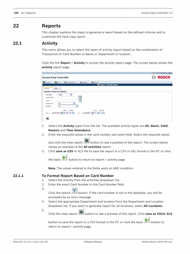
ReportsThis chapter explains the steps to generate a report based on the defined criterias and tocustomize the hard copy report.
ActivityThis menu allows you to select the types of activity report based on the combination ofTransaction or Card Number or Name or Department or location. Click the link Report > Activity to access the activity report page. The screen below shows theactivity report page.
1. Select the Activity types from the list. The available activity types are All, Alarm, Valid,Restore and Time Attendance.
2. Enter the required values in the card number and name field. Select the required values
and click the view report button to see a preview of the report. The screen belowshows an example of the All activities report.
3. Click save as CSV or XLS file to save the report in a CSV or XSL format in the PC or click
the back button to return to report > activity page.
Note: The values entered in the fields work on AND condition.
To Format Report Based on Card Number1. Select the Activity from the activities dropdown list.2. Enter the exact Card Number in the Card Number field.3.
Click the search button. If the card number is not in the database, you will beprompted by an error message.
4. Select the appropriate Department and location from the Department and Locationdropdown list. If you want to generate report for all locations, select All Locations.
5.Click the view report button to see a preview of the report. Click save as CSVor XLS
button to save the report in a CSV format in the PC or click the back button toreturn to report > activity page.
22
22.1
22.1.1
166 en | Reports Access Easy Controller 2.1
2013.05 | V1.0.5 | F.01U.122.797 Software Manual Robert Bosch (SEA) Pte Ltd

To Format Report Based on Name1.
Enter a character, a portion, or the full name in the name field. Click the search button to search the database for the entered value. If a match is found that satisfies theentry, a window will appear with the Names.
2. From the search result window, select the desired name. The selected name appears inthe Name field.
3. Select the appropriate department and location from the Department and Locationdropdown list. If you want to generate report for all location, select All Locations.
4.Click the view report button to see a preview of the report. Click save as CSVor XLS
file to save the report in a CSV or XLS format in the PC or click the back button toreturn to report > activity page.
To Format Report Based on Department1. Select the appropriate Department from the Department dropdown list.2. Select the appropriate location from the location dropdown list. If you want to generate
report for all locations, select All Locations.3.
Click the view report button to see a preview of the report. Click save as CSV or XSL
file to save the report in a CSV format or XLS format in the PC or click the back button to return to report > activity page.
To Format Report Based on Location1. Select the appropriate Location from the list.2. Select the appropriate location from the location dropdown list. If you want to generate
report for all readers, select All Locations.3.
Click the view report button to see a preview of the report. Click save as CSVor XSL
file to save the report in a CSV format or XSL format in the PC or click the back button to return to report > activity page.
To Format Report Based on Date/TimeYou can select the range of dates to view the activities in that date range. This would cutdown the time on scrolling through the list of activities if you know the date when theactivities have taken place.
APBThe APB Zones report allows you to know which cardholder is in the APB Zone at the time ofthe preview. Should there be a need to Reset APB for a particular cardholder, you can use thisreport to verify that the cardholder has actually violated the APB and not due to othercondition such as an Expired Card Number.
To Generate APB Zones ReportThis report shows the list of cardholders still in the APB zones. When a cardholder enters anAPB zone, by opening a door from an APB entry reader, the cardholder will be registered inthe system as present in the APB zone governed by the APB entry reader. Similarly, when the
22.1.2
22.1.3
22.1.4
22.1.5
22.2
22.2.1
Access Easy Controller 2.1 Reports | en 167
Robert Bosch (SEA) Pte Ltd Software Manual 2013.05 | V1.0.5 | F.01U.122.797

cardholder exits from an APB zone, by opening a door from an APB exit reader, the cardholderwill be de-registered in the system as present in the APB zone governed by the APB entryreader. 1. Click the link Report > Activity and in the activity main page select the APB tab to access
the APB report page. The screen below shows the APB report page.
2. Select the desired Zone from the APB zone dropdown list.3.
Select the required values and click the view report button to see a preview of thereport. Click save as CSVor XSL file to save the report in a CSV or XSL format in the PC
or click the back button to return to report > APB page.
Card1. Click the link Report > Card and in the card main page select the tab card to print a
report based on the cardholders. The screen below shows the card report page.
2. Enter the desired values in the appropriate fields.
22.3
168 en | Reports Access Easy Controller 2.1
2013.05 | V1.0.5 | F.01U.122.797 Software Manual Robert Bosch (SEA) Pte Ltd

3.Click the view report button to see a preview of the report. The screen below showsthe report for the search criteria based on name Maria.
4.Click the back button to return to report > card page.
Access GroupClick the link Report > Card and in the card main page select the tab Access Group to print areport based on the access groups. The screen below shows the access group page.
To Generate an Access Groups Report1. Select the desired access group from the access group dropdown list. 2.
Click the view report button to see a preview of the report. Click the back button to return to report > access groups page.
Notice!
Only Access Groups that are defined will be shown.
ReaderFollowing are the steps to generate a Card Reader Report:
22.4
22.4.1
22.5
Access Easy Controller 2.1 Reports | en 169
Robert Bosch (SEA) Pte Ltd Software Manual 2013.05 | V1.0.5 | F.01U.122.797

To Generate a Card Reader Report1. Click the link Report > Device and in the device main page select the reader tab to
access the Reader report settings. The screen below appears.
2. Select the desired Reader from the Reader Description dropdown list. Click the searchbutton to search the reader entered in the Reader Description field.
3.Click the view report button to see a preview of the report. Click the back button to return to report > reader page.
InputFollowing are the steps to generate an Input Point Report:
To Generate an Input Point Report1. Click the link Report > Device and in the device main page select the Input tab to access
the Input report settings. The screen below appears.
2. Select the desired Input point from the Input Description dropdown list. Click the searchbutton to search the Input Point entered in the Input Description field.
3.Click the view report button to see a preview of the report. Click the back button to return to report > input page.
OutputFollowing are the steps to generate an Output Point Report:
To Generate an Output Point Report1. Click the link Report > Device and in the device main page select the Output tab to
access the Output report settings. The screen below appears.
2. Select the desired output point from the Output dropdown list. Click the search buttonto search the Output Point entered in the Output field.
22.5.1
22.6
22.6.1
22.7
22.7.1
170 en | Reports Access Easy Controller 2.1
2013.05 | V1.0.5 | F.01U.122.797 Software Manual Robert Bosch (SEA) Pte Ltd

3.Click the view report button to see a preview of the report. Click the back button to return to report > output page.
Advance I/OFollowing are the steps to generate an I/O function Block Report:
To Generate an I/O Function Block Report1. Click the link Report > Device and in the device main page select the Advance I/O tab to
access the Advance I/O report settings. The screen below appears.
2. Select the desired I/O function block from the Advance I/O dropdown list. Click thesearch button to search the I/O function block entered in the AdvanceI/O field.
3.Click the view report button to see a preview of the report. Click the back button to return to report > advance I/O page.
CameraFollowing are the steps to generare a Report based on Camera:
To Generate a Report Based on Camera1. Click the link Report > Device and in the device main page select the Camera tab to
access the Camera report settings. The screen below appears.
2. Select the desired Camera from the Camera Description dropdown list. Click the searchbutton to search the Camera entered in the Camera Description field.
3.Click the view report button to see a preview of the report. Click the back button to return to report > camera page.
ScheduleFollowing are the steps to generate a Schedule report:
22.8
22.8.1
22.9
22.9.1
22.10
Access Easy Controller 2.1 Reports | en 171
Robert Bosch (SEA) Pte Ltd Software Manual 2013.05 | V1.0.5 | F.01U.122.797

To Generate a Schedule Report1. Click the link Report > Configuration and in the configuration main page select the
Schedule tab to access the Schedule report settings. The screen below appears.
2. Select the desired Schedule from the Schedule Description dropdown list. Click thesearch button to search the Schedule entered in the Schedule Description field.
3.Click the view report button to see a preview of the report. Click the back button to return to report > schedule page.
Regular HolidayFollowing are the steps to generate a Regular Holiday report:
To Generate a Regular Holiday Report1. Click the link Report > Configuration and in the configuration main page select the
Regular Holiday tab to access the Regular Holiday report settings. The screen belowappears.
2. Select the desired regular holiday from the Regular Holiday Description dropdown list.Click the search button to search the Regular Holiday entered in the Regular HolidayDescription field.
3.Click the view report button to see a preview of the report. Click the back button to return to report > regular holiday page.
Special HolidayFollowing are the steps to generate a Special Holiday Report:
To Generate a Special Holiday Report1. Click the link Report > Configuration and in the configuration main page select the
Special Holiday tab to access the Special Holiday report settings. The screen belowappears.
22.10.1
22.11
22.11.1
22.12
22.12.1
172 en | Reports Access Easy Controller 2.1
2013.05 | V1.0.5 | F.01U.122.797 Software Manual Robert Bosch (SEA) Pte Ltd

2. Select the desired regular holiday from the Special Holiday Description dropdown list.Click the search button to search the Regular Holiday entered in the Special HolidayDescription field.
3.Click the view report button to see a preview of the report. Click the back button to return to report > special holiday page.
Audit LogUser log tracks the Users operation on the AEC2.1, and logs all the action performed by theuser, such as manual on/off any output, change the settings for a Cardholder, set the date andtime, etc.
To View the User Log1. Click the link Report > Audit Log to access the user log report settings. The screen below
appears.
2. Choose the From date and To date, from the Calendar picker.3. Select the User Name from the Name dropdown list. If a particular User has been
selected, the report will only show the operation of that User. If All Names is selected,the result will show report containing all the action performed by all users on the system.
4.Click the view report button to see a preview of the report. Click save as CSV or XSL
file to save the report in a CSV or XSL format in the PC. Click the back button toreturn to report > audit log page.
View .CSV File in ExcelIn MS Excel you can only view the database details and not edit them. Follow the steps belowto view the .CSV file. Method 1
22.13
22.14
Access Easy Controller 2.1 Reports | en 173
Robert Bosch (SEA) Pte Ltd Software Manual 2013.05 | V1.0.5 | F.01U.122.797

1. Rename the Card.csv file to Card.bat. Launch MS Excel and click on File > Open. Selectthe Card.bat file from the saved location. The below window appears.
2. Select Delimited from the Original Data Type option and Unicode (UTF-8) from the FileOrigin dropdown. Click the Next button to complete the Text Import Wizard.
Method 21. Open Notepad. Click on File > Open. Select the .CSV file from the local hard disk or an
external drive and click the Open button.
174 en | Reports Access Easy Controller 2.1
2013.05 | V1.0.5 | F.01U.122.797 Software Manual Robert Bosch (SEA) Pte Ltd

2. Click on File > Save As, select Unicode from the Encoding dropdown as shown below.
3. Click the save button to save the file. Close the file.4. Launch Excel and click on File > Open. Select the Unicode Card.csv (the above saved
file) file from the saved location. The below window appears.
Access Easy Controller 2.1 Reports | en 175
Robert Bosch (SEA) Pte Ltd Software Manual 2013.05 | V1.0.5 | F.01U.122.797

5. Select Delimited from the Original Data Type option. Click the Next button to completethe Text Import Wizard.
Report - Default SettingsThe report menu consists of the default settings submenu. In the default settings you can editthe report header and sub headers. The screen below shows the default settings screen.
To Edit the Report Settings1. Type the report header in the Report Header field. For example you can type in the
company name as the Report header.2. Type the company address in Sub header 1 and Sub header 2 fields.3.
Click the save to save the settings.
22.15
22.15.1
176 en | Reports Access Easy Controller 2.1
2013.05 | V1.0.5 | F.01U.122.797 Software Manual Robert Bosch (SEA) Pte Ltd

Resetting to Factory DefaultOn the first 4-Reader board of AEC2.1 system, JP2 is used to reset the panel to factory defaultsetting. Refer to the Hardware Manual for more information.
When the jumpers on the left of JP2 (vertically), is shorted with a jumper link the systemprovides the option to retain the current settings and configuration or clear all the settingsand configuration. When the jumpers are shorted the screen below appears.
Click the Yes button to reset the AEC2.1 back to the factory default settings. This process willclear all the settings and configurations set, except for the IP address. Information like Cardnumbers and Advance IO settings will also be erased.
!Warning!
All information, settings and configurations will be erased. Users are advised to do a system
backup before proceeding (IP Address will not be reset with this function).
Click the No button to reboot the panel without changing the settings and configurations. After setting the jumper link the system will reboot. Upon system reboot, enter the AEC2.1URL address in the address field of a web browser.
23
Access Easy Controller 2.1 Resetting to Factory Default | en 177
Robert Bosch (SEA) Pte Ltd Software Manual 2013.05 | V1.0.5 | F.01U.122.797

Resetting IP Address to Default IP AddressThe jumpers on the right of JP2 (vertically), when shorted with a jumper link, will reset thepanel’s IP address back to AEC2.1 default IP address (i.e 192.168.0.41). Note that this willonly reset the IP Address back to default. No information, settings and configurations will bealtered. A reboot will be required for changes to take effect. Upon completion of rebooting,you will be able to log onto the login screen with the default IP Address.
Notice!
These two functions are independent of each other and can be carried out independently or
simultaneously.
Shorting the jumper on the left and rebooting the system will cause the panel to be reset to
factory default settings, keeping the IP Address unchanged.
Shorting the jumper on the right and rebooting the system will cause the panel to reset ONLY
the IP Address to default IP Address.
Shorting both will reset both the, configurations and settings, and IP Address.
23.1
178 en | Resetting to Factory Default Access Easy Controller 2.1
2013.05 | V1.0.5 | F.01U.122.797 Software Manual Robert Bosch (SEA) Pte Ltd

APPENDIX AThis chapter explains the initial setup required in the system to access the AEC2.1 system.
Initial Setup To Access Easy Controller 2.1Before connecting to the AEC2.1, the following conditions must be taken into consideration.They are:-1. If the Central Monitoring Computer (CMC) is not connected to a Network as in a
standalone.2. If the CMC is connected to a Network. For case 1, having the CMC as a stand-alone unit, either IP Address for the AEC2.1 or CMC canbe changed to suit the other. For an initial set-up, a Notebook or a Personal Computer either stand-alone or taken from anexisting network have to be used. For either case, there must be a 10Base-T Ethernet cardinstalled and with a running web browser program such as Internet Explorer, version 7.0 andlater. Connect the AEC2.1 server and Notebook using the industrial standard UTP Category 5 cableas shown below.
Notice!
The cable has to be terminated and polarized accordingly as shown.
The below drawing shows the Transmit (T+ & T-) and Receive (R+ & R-) lines between bothend of the connectors being twisted. The wires for pins 4, 5, 7 and 8 are connected withouttwisting at both end of the connectors, but are not drawn above. The drawing below showsthe full pin-to-pin connections with cable color coding.
24
24.1
Access Easy Controller 2.1 APPENDIX A | en 179
Robert Bosch (SEA) Pte Ltd Software Manual 2013.05 | V1.0.5 | F.01U.122.797

The individual conductors must be arranged as indicated above, taking reference to the pinnumbers on the left (standard).
Configuring a Web Browser to Work with Access EasyController 2.1The instructions in this section describes the steps necessary to configure the Web browser tooperate with the AEC2.1. In most instances, you will not need to make any changes to thesetup of a Web browser to connect to an AEC2.1. Follow the steps below to configure Microsoft's Internet Explorer version 7.0 and above. 1. Launch Internet Explorer and in the menu bar select Tools > Internet Options. The
screen below appears.
2. If you want the AEC2.1 login page to open every time you activate your Web browser,then set the Home page Address to the AEC2.1's assigned IP address in the Address field.
3.Under Temporary Internet Files, click the settings button to display thesettings dialog box as shown below. Confirm that the option in Check for newer versionsof stored pages is set to Every time I visit the webpage as shown below. If it is not,select the corresponding radio button to select this option. This step is necessary toupdate the ‘Activity’ user interface menu and to transfer the images from the server to thesystem periodically. The ’Activity > Transactions’ menu lists all the activities performedby the AEC panel.
4.Click the button to save the changes and exit from the Settings windows.You will return to the Internet Option dialog box as shown in point 1.
24.2
180 en | APPENDIX A Access Easy Controller 2.1
2013.05 | V1.0.5 | F.01U.122.797 Software Manual Robert Bosch (SEA) Pte Ltd

5. From the Internet Option screen, select the Connections tab to display the Connectionsdialog box. This screen below appears.
6.Click to display the LAN Settings dialog box.
Access Easy Controller 2.1 APPENDIX A | en 181
Robert Bosch (SEA) Pte Ltd Software Manual 2013.05 | V1.0.5 | F.01U.122.797
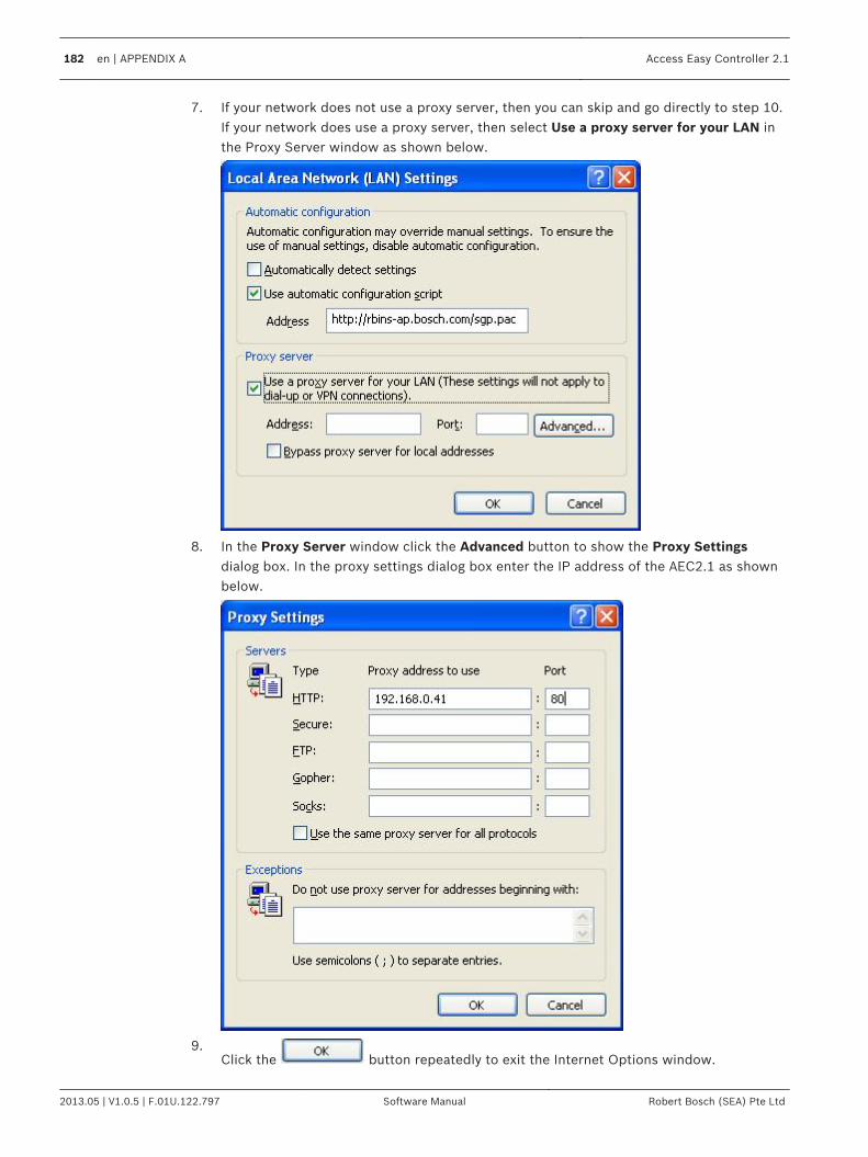
7. If your network does not use a proxy server, then you can skip and go directly to step 10.If your network does use a proxy server, then select Use a proxy server for your LAN inthe Proxy Server window as shown below.
8. In the Proxy Server window click the Advanced button to show the Proxy Settingsdialog box. In the proxy settings dialog box enter the IP address of the AEC2.1 as shownbelow.
9.Click the button repeatedly to exit the Internet Options window.
182 en | APPENDIX A Access Easy Controller 2.1
2013.05 | V1.0.5 | F.01U.122.797 Software Manual Robert Bosch (SEA) Pte Ltd
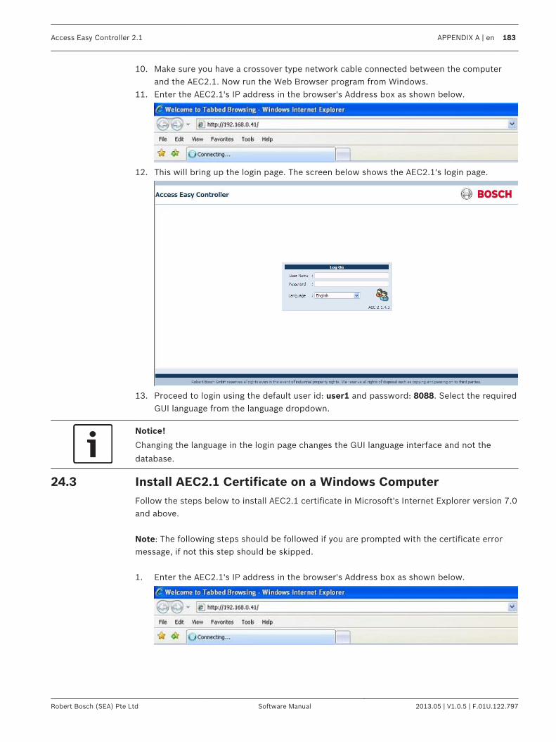
10. Make sure you have a crossover type network cable connected between the computerand the AEC2.1. Now run the Web Browser program from Windows.
11. Enter the AEC2.1's IP address in the browser's Address box as shown below.
12. This will bring up the login page. The screen below shows the AEC2.1's login page.
13. Proceed to login using the default user id: user1 and password: 8088. Select the requiredGUI language from the language dropdown.
Notice!
Changing the language in the login page changes the GUI language interface and not the
database.
Install AEC2.1 Certificate on a Windows ComputerFollow the steps below to install AEC2.1 certificate in Microsoft's Internet Explorer version 7.0and above. Note: The following steps should be followed if you are prompted with the certificate errormessage, if not this step should be skipped. 1. Enter the AEC2.1's IP address in the browser's Address box as shown below.
24.3
Access Easy Controller 2.1 APPENDIX A | en 183
Robert Bosch (SEA) Pte Ltd Software Manual 2013.05 | V1.0.5 | F.01U.122.797
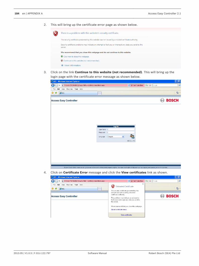
2. This will bring up the certificate error page as shown below.
3. Click on the link Continue to this website (not recommended). This will bring up thelogin page with the certificate error message as shown below.
4. Click on Certificate Error message and click the View certificates link as shown.
184 en | APPENDIX A Access Easy Controller 2.1
2013.05 | V1.0.5 | F.01U.122.797 Software Manual Robert Bosch (SEA) Pte Ltd

5. The screen below shows the certificate dialog.
Access Easy Controller 2.1 APPENDIX A | en 185
Robert Bosch (SEA) Pte Ltd Software Manual 2013.05 | V1.0.5 | F.01U.122.797
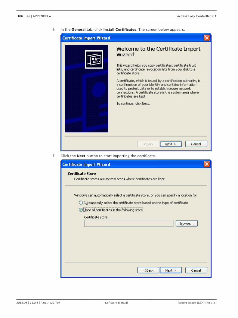
6. In the General tab, click Install Certificates. The screen below appears.
7. Click the Next button to start importing the certificate.
186 en | APPENDIX A Access Easy Controller 2.1
2013.05 | V1.0.5 | F.01U.122.797 Software Manual Robert Bosch (SEA) Pte Ltd

8. Select the radio button Place all certificates in the following store. Click the Browsebutton to select a location to save the certificates. The following window pops up for youto select the location.
9. Select the location Trusted Root Certificate Authorities and click the OK button.
Access Easy Controller 2.1 APPENDIX A | en 187
Robert Bosch (SEA) Pte Ltd Software Manual 2013.05 | V1.0.5 | F.01U.122.797

10. Click the Finish button to complete the installation. The following security warningprompts.
11. Click Yes to complete the installation. Enter the AEC2.1's IP address in the browser'sAddress box and the AEC2.1 login page appears without the certificate error message.
188 en | APPENDIX A Access Easy Controller 2.1
2013.05 | V1.0.5 | F.01U.122.797 Software Manual Robert Bosch (SEA) Pte Ltd

APPENDIX BThis section provides procedure to set the IP Address for the PC.
Procedure to set the IP Address of computerFollow through the procedures to set the IP Address of the PC.
Notice!
The example described here is based on Windows 98 and Internet Explorer 5.
Differencesmight appear for the dialog box, displays, or description if other version or
different operatingsystem is used. However, the principle of setting is the same.
1.Click the button, followed by Settings > Control Panel > NetworkConnections.
2.
Double-click the existing network connection icon and select Properties, thescreen below appears.
3. Look up for Internet Protocol TCP/IP from the list. If the component is found, highlight itby single clicking on it. Then skip forward to step 8 of this procedure. However if thecomponent is not found, continue with steps 4 to 7 and install the component.
25
25.1
Access Easy Controller 2.1 APPENDIX B | en 189
Robert Bosch (SEA) Pte Ltd Software Manual 2013.05 | V1.0.5 | F.01U.122.797

4. If Internet Protocol TCP/IP is not found, then you need to install it. To add the TCP/IP
component, click the button, the screen below appears:
5.Highlight the Protocol by single clicking on it, and then click the button.
6. The dialog box below appears. From this box, select Microsoft TCP/IP version 6 in theNetwork Protocol window.
7.Click the button to proceed with the component installation. Follow anyinstructions that may be displayed on the screen. Note that the system may ask you toinsert your Windows Installation Disk in the CD ROM drive. When done, go back to step 3and select the TCP/IP Protocol - network adapter line from the list of installed networkcomponents. Then proceed to step. 8.
190 en | APPENDIX B Access Easy Controller 2.1
2013.05 | V1.0.5 | F.01U.122.797 Software Manual Robert Bosch (SEA) Pte Ltd

8.With the TCP/IP - adapter component highlighted, click the button todefine the TCP/IP Properties. The TCP/IP properties dialog box appears as shown below.
9. Select Use the following IP address radio button. This will enable the fields for IPAddress and Subnet Mask.
Access Easy Controller 2.1 APPENDIX B | en 191
Robert Bosch (SEA) Pte Ltd Software Manual 2013.05 | V1.0.5 | F.01U.122.797

10. Enter the IP Address and Subnet Mask Address. The following examples shows therecommended address and subnet mask to assign to the computer to communicate witha brand new AEC2.1 as received from the factory. Leave DNS field blank.
11.Click the button after verifying the IP address and subnet mask.
12. The computer will proceed to configure the TCP/IP settings. When completed, you will beprompted to reboot the computer for the new settings to take effect.
192 en | APPENDIX B Access Easy Controller 2.1
2013.05 | V1.0.5 | F.01U.122.797 Software Manual Robert Bosch (SEA) Pte Ltd
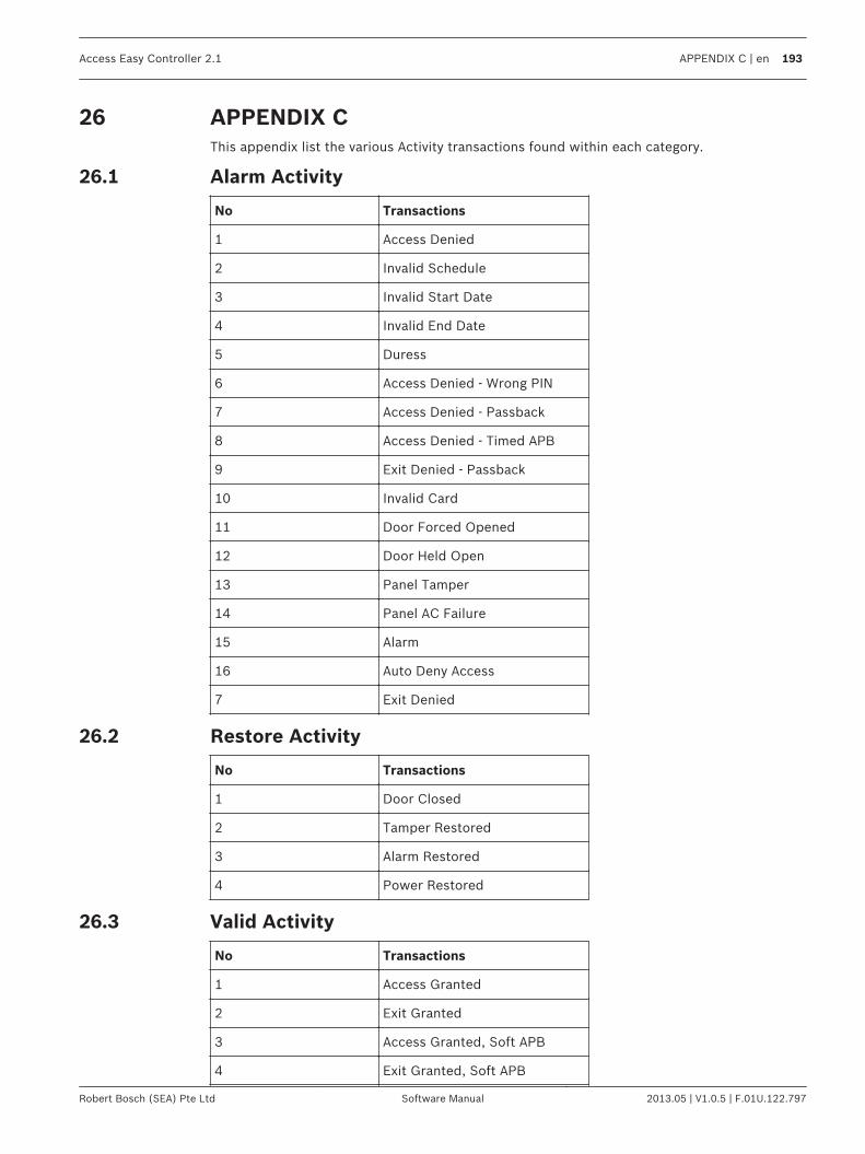
APPENDIX CThis appendix list the various Activity transactions found within each category.
Alarm Activity
No Transactions
1 Access Denied
2 Invalid Schedule
3 Invalid Start Date
4 Invalid End Date
5 Duress
6 Access Denied - Wrong PIN
7 Access Denied - Passback
8 Access Denied - Timed APB
9 Exit Denied - Passback
10 Invalid Card
11 Door Forced Opened
12 Door Held Open
13 Panel Tamper
14 Panel AC Failure
15 Alarm
16 Auto Deny Access
7 Exit Denied
Restore Activity
No Transactions
1 Door Closed
2 Tamper Restored
3 Alarm Restored
4 Power Restored
Valid Activity
No Transactions
1 Access Granted
2 Exit Granted
3 Access Granted, Soft APB
4 Exit Granted, Soft APB
26
26.1
26.2
26.3
Access Easy Controller 2.1 APPENDIX C | en 193
Robert Bosch (SEA) Pte Ltd Software Manual 2013.05 | V1.0.5 | F.01U.122.797

No Transactions
5 PIN Changed
6 Disarmed
7 Armed
8 Turn On
9 Turn Off
10 Door Locked
11 Door Unlocked
12 Door Locked By Schedule
13 Door Unlocked By Schedule
14 Door Momentarily Unlocked
15 Door Access Enabled
16 Door Access Disabled
17 Armed By Schedule
18 Disarmed By Schedule
19 Bypassed
20 Turned Off By Schedule
21 Turned On By Schedule
22 Duration Off
23 Duration On
24 Grant Access
25 Auto Grant Access
26 Access Granted - No Entry
27 Exit Granted - No Entry
28 Access Soft APB - No Entry
29 Exit Soft APB - No Entry
30 Grant Access - No Entry
31 Auto Grant Access - No Entry
Time Attendance
No Transactions
1 Clock In
2 Clock Out
26.4
194 en | APPENDIX C Access Easy Controller 2.1
2013.05 | V1.0.5 | F.01U.122.797 Software Manual Robert Bosch (SEA) Pte Ltd


Robert Bosch (SEA) Pte Ltd
11 Bishan Street 21
573943 Singapore
Singapore
www.boschsecurity.com
© Robert Bosch (SEA) Pte Ltd, 2013