ACCE.S5lON Ferry Nuclear OC Stationi Unit li Ferry Nuclear ...
54
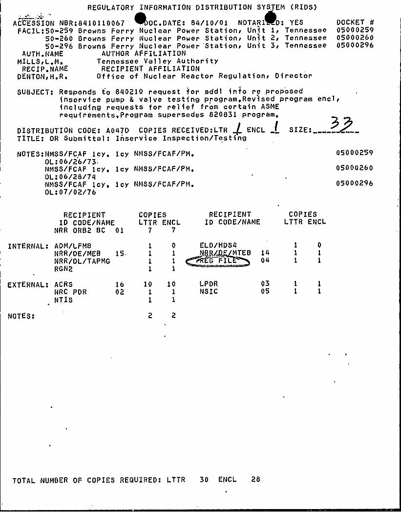
REGULATORY INFORMATION DISTRIBUTION SYSTEM (RIDS) ACCE.S5lON NBR:8410110067 OC DATE: 84/10/01 NOTARI D: YES FACIL:50-259 Browns Ferry Nuclear Power Stationi Unit li Tennessee 50-260 Browns Ferry Nuclear Power Stations Unit 2< Tennessee 50-296 Browns Ferry Nuclear Power 'Stations Unit 3< Tennessee AUTH. NAME AUTHOR AFFILIATION MILLSg L,M» Tennessee Valley Authority RECIP ~ NAME RECIPIENT AFFILIATION DENTONgH ~ RE Office of Nuclear Reactor Regulationi Director DOCKET 05000259 05000260 05000296 SUBJECT: Responds to 800210 request for addi info re proposed inser vice pump 8 valve testing program. Revised program encl/ including requests for relief from certain ASME requirements, Program supersedes 820831 program, DISTRIBUTION CODE: A047D COPIES RECEIVED:LTR ENCL SIZE; TITLE. "OR Submittal: Inservice Inspection/Testing NOTES:NMSS/FCAF 1cy. 1cy NMSS/FCAF/PM'L:06/26/73 NMSS/FCAF 1cy, 1cy NMSS/FCAF/PM'L:06/28/7q NMSS/FCAF 1cy. 1cy NMSS/FCAF/PM'Lo07/0?/76 05000?59 05000260 05000296 RECIPIENT ID CODE/NAME NRR ORB2 BC 01 COPIES LTTR ENCL 7 7 RECIPIENT ID CODE/NAME COPIES LTTR ENCL INTERNAL: ADM/LFMB NRR/DE/MEB 15 NRR/DL/TAPMG RGN2 1 0 ELD/HDSO 1 1 gg/ MTEB 14 1 1 rRE'G FIL 04 1 1 EXTERNAL: ACRS NRC PDR NTIS NOTES; 16 10 10 02 1 1 1 1 LPDR NSIC 03 05 TOTAL NUMBER OF COPIES REQUIRED! LTTR 30 ENCL 28
Transcript of ACCE.S5lON Ferry Nuclear OC Stationi Unit li Ferry Nuclear ...
REGULATORY INFORMATION DISTRIBUTION SYSTEM (RIDS)
ACCE.S5lON NBR:8410110067 OC DATE: 84/10/01 NOTARI D: YESFACIL:50-259 Browns Ferry Nuclear Power Stationi Unit li Tennessee
50-260 Browns Ferry Nuclear Power Stations Unit 2< Tennessee50-296 Browns Ferry Nuclear Power 'Stations Unit 3< Tennessee
AUTH.NAME AUTHOR AFFILIATIONMILLSg L,M» Tennessee Valley Authority
RECIP ~ NAME RECIPIENT AFFILIATIONDENTONgH ~ RE Office of Nuclear Reactor Regulationi Director
DOCKET050002590500026005000296
SUBJECT: Responds to 800210 request for addi info re proposedinser vice pump 8 valve testing program. Revised program encl/including requests for relief from certain ASMErequirements, Program supersedes 820831 program,
DISTRIBUTION CODE: A047D COPIES RECEIVED:LTR ENCL SIZE;TITLE."OR Submittal: Inservice Inspection/Testing
NOTES:NMSS/FCAF 1cy. 1cyNMSS/FCAF/PM'L:06/26/73
NMSS/FCAF 1cy, 1cyNMSS/FCAF/PM'L:06/28/7q
NMSS/FCAF 1cy. 1cyNMSS/FCAF/PM'Lo07/0?/76
05000?59
05000260
05000296
RECIPIENTID CODE/NAME
NRR ORB2 BC 01
COPIESLTTR ENCL
7 7
RECIPIENTID CODE/NAME
COPIESLTTR ENCL
INTERNAL: ADM/LFMBNRR/DE/MEB 15NRR/DL/TAPMGRGN2
1 0 ELD/HDSO1 1 gg/ MTEB 141 1 rRE'G FIL 041 1
EXTERNAL: ACRSNRC PDRNTIS
NOTES;
16 10 1002 1 1
1 1
LPDRNSIC
0305
TOTAL NUMBER OF COPIES REQUIRED! LTTR 30 ENCL 28
4 ~
1 E
li
lpll
ll
'I
4
k
h
il
;-0 ~TENNESSEE VALLEYAUTHORITY
cHATTANooGA. TENNEssEE 37401
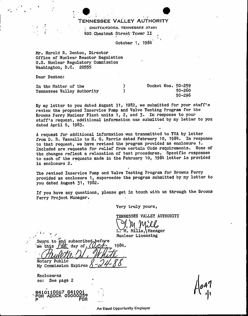
400,Chestnut 'Street"Tower IIOctober 1, 1984
Mr. Harold R. Denton, DirectorOffice of Nuclear Reactor RegulationU.S. Nuclear Regulatory CommissionWashington, D.C. 20555
Dear Denton:
In the Matter of theTennessee Valley Authority
Docket Nos. 50-25950-26050-296
By my letter to you dated August 31, 1982, we submitted for your staff'sreview the proposed Inservice Pump and Valve Testing Program for theBrowns Ferry Nuclear Plant units 1, 2, and 3. In response to yourstaff's request;, additional information was submitted by my letter to youdated April 6, 1983.
I
A request for additional information was transmitted to TVA by letterfrom D. B. Vassallo to H. G. Parris dated February 10, 1984. In responseto that request, we have revised the program provided as enclosure 1.Included are requests for relief from certain Code requirements. None ofthe changes reflect a relaxation of test procedures. Specific responsesto each of the requests made in the February 10, 1984 letter is providedin enclosure 2.
The revised Inservice Pump and Valve Testing Program for Browns Ferryprovided as enclosure 1, supersedes the program submitted by my letter toyou dated August 31, 1982.
If you have any questions, please get in touch with us through the Browns
Ferry Project Manager.
Very truly yours,
d
Sworn to .ng subscribeme th s 'M day of
TENNESSEE VALLEY AUTHORITY
c
L. M. Mills, ManagerNuclear Licensing
befo e1984.
Notar y PublicMy Commission Expires
Enclosurescc: See page 2
„84iOii0067 84100i
"PDR ADOCK 05000259P PDR
An Equal Opportunity Employer
l
9 'I
~ k'y( '~'I'g
g '$P lt t', 1 *I F
F" '
~ ~ . 'P C
f 'h I JI
S y I
I' ae F h
4
r-1 4 ~ A
N
ll
h
0
II
V L
-~ p l
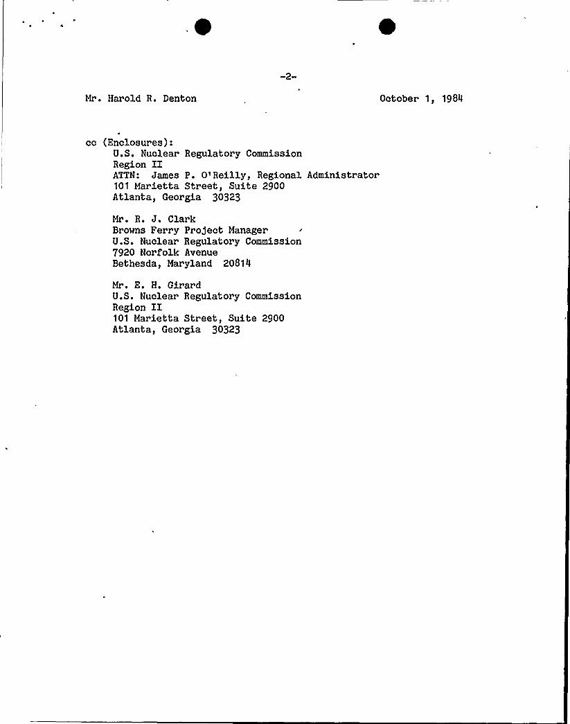
Mr. Harold R. Denton October 1, 1984
cc (Enclosures):U.S. Nuclear Regulatory CommissionRegion IIATTN: James P. O'Reilly, Regional Administrator101 Marietta Street, Suite 2900Atlanta, Georgia 30323
Mr. R. J. ClarkBrowns Ferry Project ManagerU.S. Nuclear Regulatory Commission7920 Norfolk AvenueBethesda, Maryland 20814
Mr. E. H. GirardU.S. Nuclear Regulatory CommissionRegion II101 Marietta Street, Suite 2900Atlanta, Georgia 30323
1
ENCLOSURE 1
ASME SECTION XI INSERVICE PUMP
AND VALVE TESTING PROGRAMBROMNS FERRY NUCLEAR PLANT
UNITS 1, 2, AND 3(DOCKET NOS. 50-259, -260, -296)
Attachment 1: Inservice Testing Program for ASME Code Classes 1, 2, and 3Pumps
Attachment 2: Valves to be Cycled for ASME Section XI (IWV-3410, 3510,3520, and 3610)
Attachment 3: Category A Valves and Testing Criteria (Appendix J, Secti'onXI, or both)
Attachment 4: Requests for Relief
1 ~
AXiKP29K 1
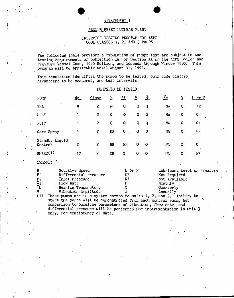
ItJSERVICE leSTIN'i PKCP~uk FOR AS c.CODE CLASSES 1, 2, AtJD 3 PU."'PS
The following table provide" a tabulation of pmps thattesting requirements of Sub"ecticn IMP of Section XI ofPressur": Vessel Code, 1980 Edi'icn, and Add nda thrcughp. ograrn will be applicable until August 31, 1992.
are subjec'c t'.ethe I~YZ J.'w ler andHinter 19tC. Thi s
This tabulation identifies the pcnps to be tes'ed, pup code classes,pararne'ers to be rneasur ed, and test irtervals.
HPCI.
RCIC
Core Spray
Standby LiquidControl
RFIRS'„'( 1 )
2 NR Q 0 Q
2 Q Q Q 0
2 Q 0 Q 0
JJR Q Q Q
'2 2 lJR JR Q Q
3 tJR Q Q Q
H~ Ma~ 3 Zi Z
tJA
tJA
0 0<
Q JJR
'JA Q
tJA' !JR
J ~n
tJA 0 NR
tJA ~ 0 0
H Rotative Speed Lor P Lubricant Level or Pressur"P'ifferential Pressr:r e tJR tarot RequiredPi Inlet Pres ure tJA tJo AvailableQi Flow Rate H Mcntrg yTb Bearir:g Temperature Q QuarterlyV Vibraticrr Anrpl i tude A Annually(1) These punps are ir a systerr ccexnon to units 1, 2, and 3. Ability to
start the pumps will be derncnstrated frcrn each control roan, butcanparison to baseline parameters of vibraticn, flew rate, anddifferential pressure will be perfcrrned for instrumentation in unit 3only, for ccnsistency of d'ata.

4 ~
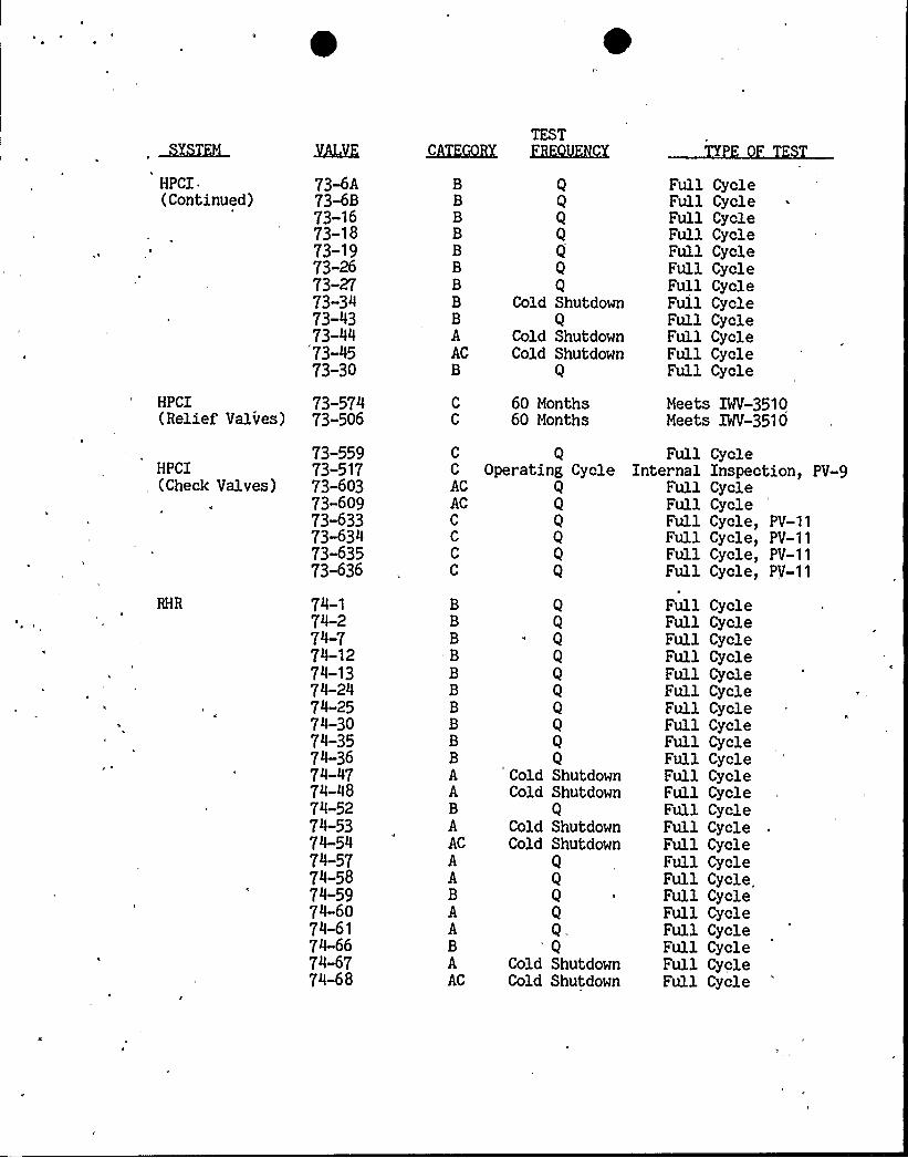
The following table provides a listing of systems, valve numbers, types,
categories, test frequencies, and type of tests for those valves to beI
cycled in accordance with ASME Section XI, IHV-3410, 3510, 3520, and 3610.
4
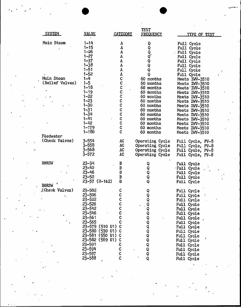
Main Steam
Main Steam(Rel'ief Valves)
Feedwater(Check Valves)
XLQD'.
1-141-151-261-271-371-381-511-521-41-51-181-191-221-231-301-311-341-411-421-1791-180
3-5543-5583-5683-572
23-3423-4023-4623-5223-57 ( U-142)
AAAAAAAAC
C
C
C
C
C
C
C
C
C
C
C
C
ACACACAC
TESTHKQXH<Y
Q
Q
Q
Q
60 months60 months60 months60 months60 months60 months60 months60 months60 months60 months60 months60 months60 months
Operating CycleOperating CycleOperating CycleOperating Cycle
Full CycleFull CycleFull CycleFull CycleFull CycleFull CycleFull CycleFull CycleMeets IWV-3510Meets IWV-3510Meets'IWV-3510Meets IWV-3510Meets IWV-3510Meets IWV-3510Meets IWV-3510Meets IWV-3510Meets IWV-3510Meets IWV-3510Meets IWV-3510Meets Mf-3510Meets IWV-3510
Full Cycle, PV-8Full Cycle, PV-8Full Cycle, PV-8Full Cycle, PV-8
Full Cycle- Full CycleFull CycleFull CycleFull Cycle
RHRSW
,(Check Valves) 23-50223-50623-52223-52623-54223-54623-56123-56523-57923-58023-58123-58223-59123-59423-59723-588
C
C
C
C
C
C
C
C
(510 U1) C
(530 U1) C
(550 U1) C
(569 U1) C
C
C
C
C
Q
Q
Q
Q
Q
Q
Q
Q
Q
Q
Q
Q
Q
Q
Full CycleFull, CycleFull CycleFull CycleFull CycleFull CycleFull CycleFull CycleFull CycleFull CycleFull CycleFull CycleFull Cycle
- Full CycleFull CycleFull Cycle
~Y~gM
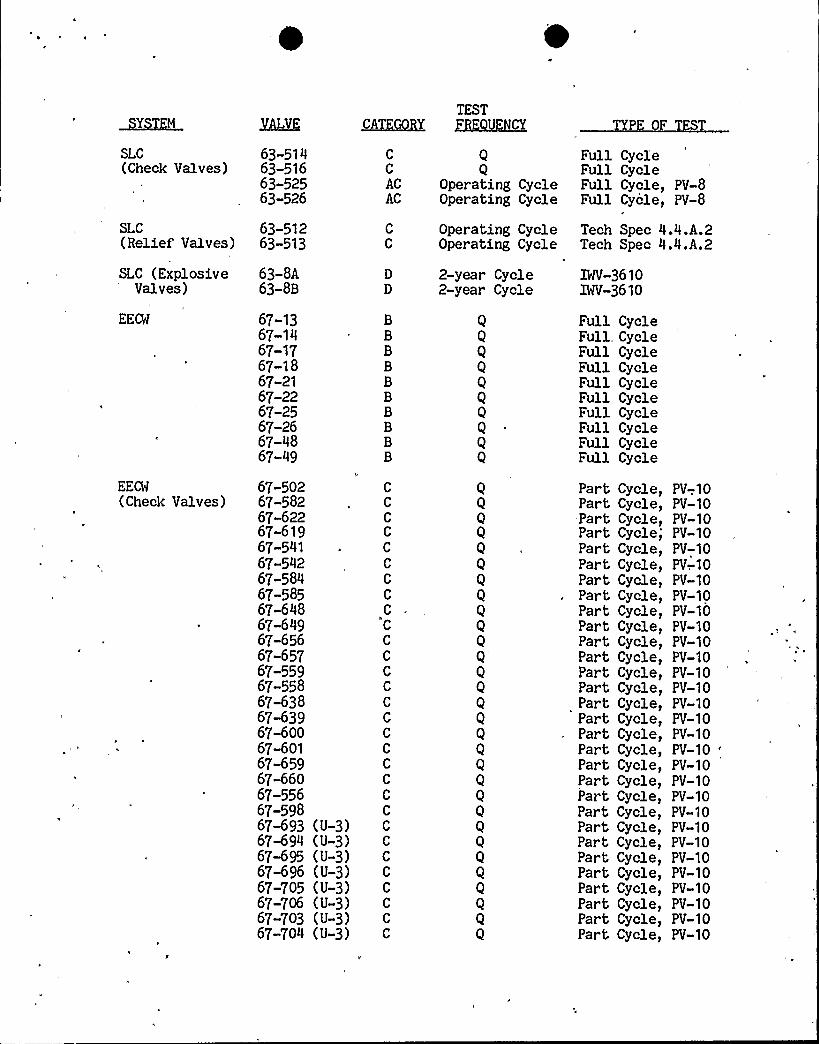
SLC(Check Valves)
63-51463-51663-52563-526
MCXKQBX
C
C
ACAC
TESTGKQUKKX
Operating CycleOperating Cycle
P OF
Full CycleFull CycleFull Cycle,Full Cycle,
PV-8PV-8
SLC(Relief Valves)
SLC (ExplosiveValves)
EE%
63-51263-513
63-SA63-SB
67-1367-1467-1767-1867-2167-2267-2567-2667-4867-49
2-year2-year
CycleCycle
Operating CycleOperating Cycle
Tech Spec 4.4.A.2Tech Spec 4.4.A.2
IWV-36101WV-3610
Full CycleFull. CycleFull CycleFull CycleFull CycleFull CycleFull CycleFull CycleFull CycleFull Cycle
EEL(Check Valves)
67-50267-58267-62267-61967-54167-54267-58467-58567-64867-64967-65667-65767-55967»55867-63867<3967-60067-60167-65967-66067-55667-59867693 (U-3)67-694 (U-3)67%95 (U-3)67-696 (U-3)67-705 (U-3)67-706 (U-3)67-703 (U-3)67-704 (U-3)
C
C
C
C
C
C
C
C
C
C
C
Q
Q
Q
Q
Q
Q
Q
Q
Q
Q
Q
Q
Q
Q
Q
Q
Q
Q
Q
Q
Part Cycle,Part Cycle,Part Cycle,Part Cycle,Part Cycle,Part Cycle,Part Cycle,Part Cycle,Part Cycle,Part Cycle,Part Cycle,Part Cycle,Part Cycle,Part Cycle,Part Cycle,Part Cycle,Part Cycle,Part Cycle,Part Cycle,Part Cycle,Part Cycle,Part Cycle,Part Cycle,Part Cycle,Part Cycle,Part Cycle,Part Cycle,Part Cycle,Part Cycle,Part Cycle,
PV-,10PV-10PV-10PV-10PV-10PV-.10PV-10PV-10PV-10PV-10PV-10PV-10PV-10PV-10PV-10PV-10PV-10PV-10PV-10PV-10PV-10PV-10PV-10PV-10PV-10PV-10PV-10PV-10PV-10PV-10

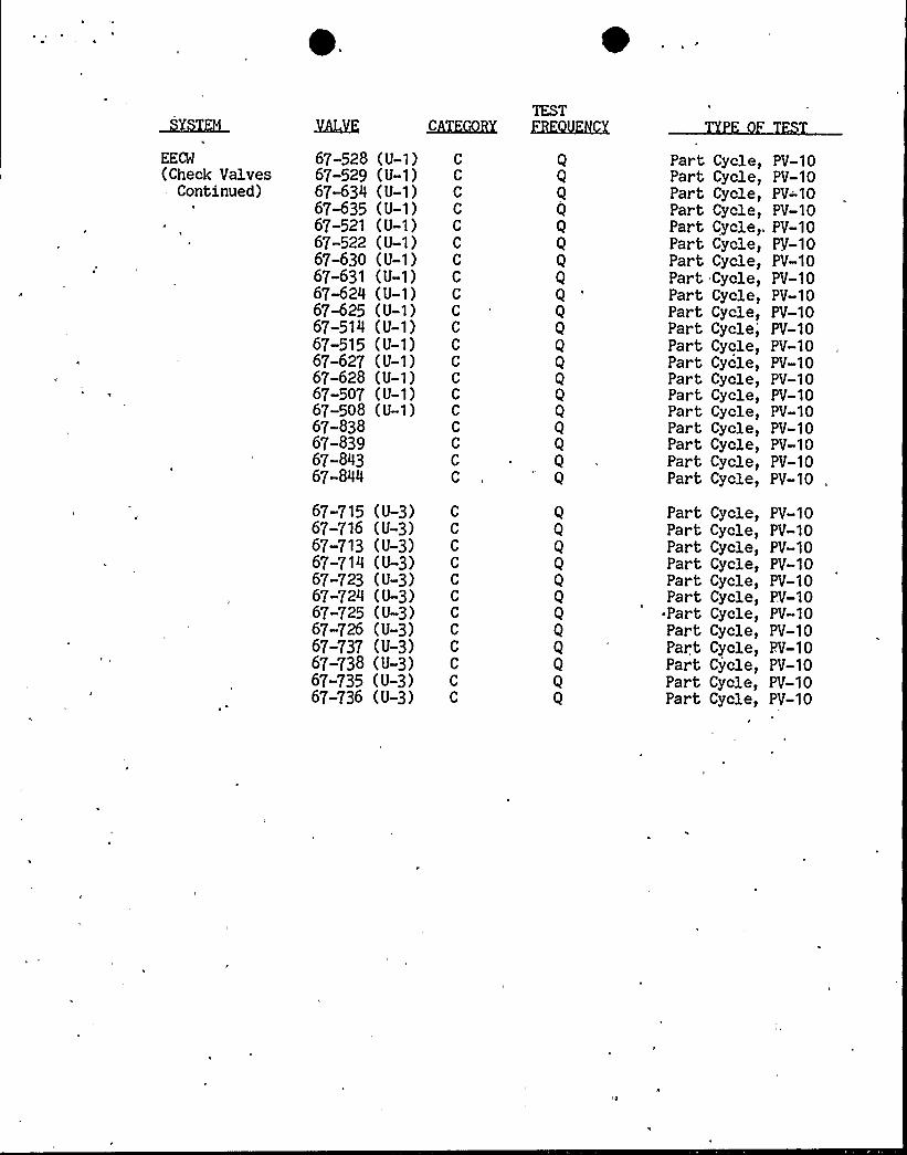
EECM(Check Valves
- Continued)
67-528 (U-1)67-529 (U-1)67%34 (U-1)67%35 (U-1)67-521 (U-1)67-522 (U-1)67-630 (U-1)67-631 (U-1)67-624 (U»1)67-625 (U-1)67-514 (U-1)67-515 (U-1)67-627 (U-1)67-628 (U-1)67-507 (U-1)67-508 (U-1)67-83867-83967-84367-844
KQBX
CC
C
C
C
C
C
C
C
C
C
C
C
C
CC
CC
C
C
TESTZEK8LKKX
Q
Q
Q
Q
Q
Q
Q
Q
Q
Q
Part Cycle,Part Cycle,Part Cycle,Part Cycle,Part Cycle,Part Cycle,Part Cycle,Part Cycle,Part Cycle,Part Cycle,,Part Cycle,Part Cycle,Part Cycle,Part Cycle,
PV-10PV-10PV-10PV-10PV-10PV-10PV-10PV-10PV-10PV-10PV-10PV-10PV-10PV-10
Part Cycle, PV-10Part Cycle, PV-10Part Cycle, PV-10Part Cycle, PV-10Part Cycle,. PV-10Part Cycle, PV-10
67-715 (U-3)67-716 (U-3)67-713 (U-3)67-714 (U-3)67-723 (U-3)67-724 (U-3)67-725 (U-3)67-726 (U-3)67-737 (U-,3)67-738 (U-3)67-735 (U-3)67-736 (U-3)
Q
Q
Q
Q
Q
Q
Q
Q
Part Cycle,Part Cycle,Part Cycle,Part Cycle,Part Cycle,Part Cycle,Part Cycle,Part Cycle,Part Cycle,Part Cycle,Part Cycle,Part Cycle,
PV-10PV-10PV-10PV-10PV-10PV-10PV-10PV-10PV-10PV-10PV-10PV-10
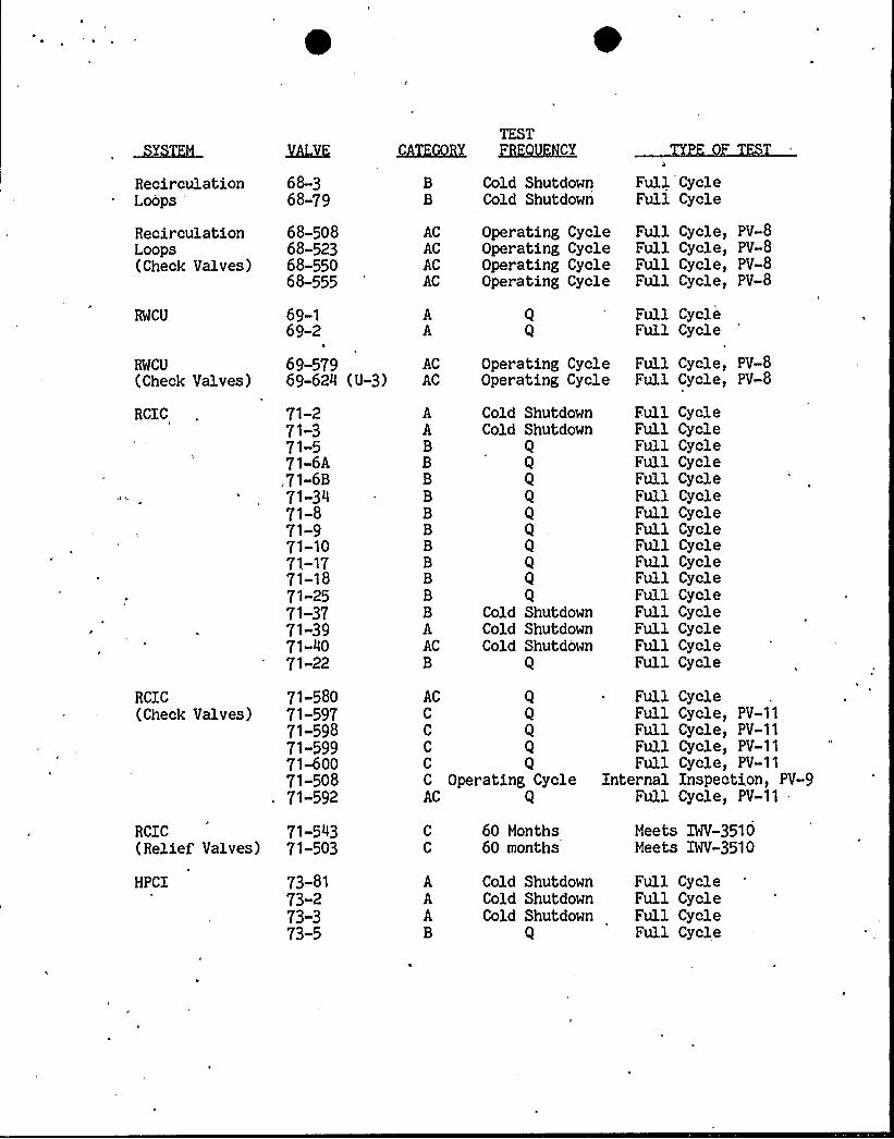
RecirculationLoops
68-368-79
TEST~CKBX HMlKhLCX
Cold ShutdownCold Shutdown
Full CycleFull Cycle
RecirculationLoops(Check Valves)
68-50868-52368-55068-555
ACACACAC
Operating CycleOperating CycleOperating CycleOperating Cycle
FullFullFullFull
Cycle,Cycle,Cycle,Cycle,
PV-8PV-8PV-8PV-8
RWCU
RWCU
(Check Valves)
RCIC
69-169-2
69-57969-624
71-271-371-571-6A,71-6B71-3471-871-971-1071-1771-1871-2571-3771-3971-4071-22
(U-3)-AC
AC
AABBBBBBBBBBBAACB
Operating CycleOperating Cycle
Cold ShutdownCold Shutdown
Q
Q
Q
Q
Q
Q
Q
QCold ShutdownCold ShutdownCold Shutdown
Q
FullFull
FullFull
CycleCycle
Cycle,Cycle,
Full CycleFull CycleFull CycleFull CycleFull CycleFull CycleFull CycleFull CycleFull CycleFull CycleFull CycleFull CycleFull CycleFull CycleFull CycleFull Cycle
PV-8PV-8
RCIC(Check Valves)
RCIC(Relief Valves)
HPCI
71-58071-59771-59871-59971-60071-50871-592
71-54371-503
73-8173-273-373-5
AC QC QC QC QC QC Operating CycleAC Q
60 Months60 months
Cold ShutdownCold ShutdownCold Shutdown
Q
FullFullFullFullFull
CycleCycle,Cycle,Cycle,Cycle,
PV-11PV-11PV-11PV-11
Full CycleFull CycleFull CycleFull Cycle
Internal Inspection, PV-9Full Cycle, PV-11
Meets IWV-3510Meets IWV-3510
TESTMCZKEK ZlKQL~~Y
HPCI ~
(Continued)
HPCI(Relief Valves)
HPCI(Check Valves)
RHR
73-6A73-6B73-1673-1873-1973-2673-2773-3473-4373 44
'73-4573-30
73-57473-506
73-55973-51773-60373-60973-63373-63473-63573-636
74-174-274-774-1274-1374-2474-2574-3074-3574-3674 4774-4874-5274-5374 5474-5774-5874-5974-6074-6174-6674-6774-68
BBBBBBBBBAACB
C
C
ACACC
C
C
C
BBBBBBBBBBAABAACAABAABAAC
Q
Q
QCold Shutdown
QCold ShutdownCold Shutdown
Q
60 Months60 Months
QOperating Cycle
Q
Q
QQQ
Q
Q
Q
Q
Q
Q
Q
Q
Q
Q
QCold ShutdownCold Shutdown
QCold ShutdownCold Shutdown
Q
Q
Q.'Q
Cold ShutdownCold Shutdown
Full CycleFull CycleFull CycleFull CycleFull CycleFull CycleFull CycleFull CycleFull CycleFull CycleFull CycleFull Cycle
Meets IHV-3510Meets IHV-3510
CycleCycleCycle,Cycle,Cycle,Cycle,
FullFullFullFullFullFull
FullFullFullFullFullFullFullFullFullFullFullFullFullFullFullFullFullFullFullFullFullFullFull
PV-11PV-11PV-11PV-11
CycleCycleCycleCycleCycleCycleCycleCycleCycleCycleCycleCycleCycleCycleCycleCycleCycle,CycleCycleCycleCycleCycleCycle
Full CycleInternal Inspection, PV-9
. ~GAL
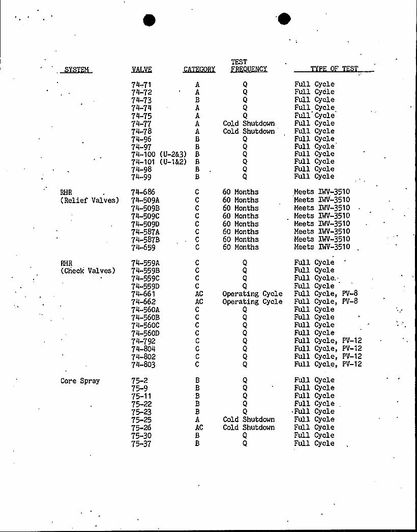
RHR
(Relief Valves)
74-.7174-7274-7374 7474-7574-7774-7874-9674-9774-10074-10174-9874-99
74-68674-509A74-509B74-509C74-509D74-587A74-587B74-659
(U-28 3)(U-18 2)
AABAAAABBBBBB
TESTZBKKFJLX
Q
Q
QCold ShutdownCold Shutdown
QQQQQQ
60 Months60 Months60 Months60 Months60 Months60 Months60 Months60 Months
Full CycleFull CycleFull CycleFull CycleFull CycleFull CycleFull CycleFull CycleFull CycleFull CycleFull CycleFull CycleFull Cycle
Meets IWV-3510Meets IWV-3510Meets IWV-3510Meets IWV-3510Meets IWV-3510Meets IWV-3510Meets IWV-3510Meets IWV-3510
RHR(Check Valves)
Core Spray
74-559A74-559B74-559C74-559D74-66174-66274-560A74-560874«560C74-560D74-79274-80474-80274-803
75-275-975-1175-2275-2375-2575-2675-3075-37
C
C
C
C
ACACC
C
C
C
C
C
C
C
BBBBBAACBB
Q
Q
Q
QOperating CycleOperating Cycle
Q
Q
Q
Q
QQQQ
QCold ShutdownCold Shutdown
Q
Q
Full CycleFull CycleFull Cycle.Full CycleFull Cycle, PV-8Full Cycle, PV-8Full CycleFull CycleFull CycleFull CycleFull Cycle, PV-12Full Cycle, PV-12Full Cycle, PV-12Full Cycle, PV-12
Full CycleFull CycleFull CycleFull Cycle „
~ Full CycleFull CycleFull CycleFull CycleFull Cycle
)LEAKTEST
QKKQQBX GEQXKK
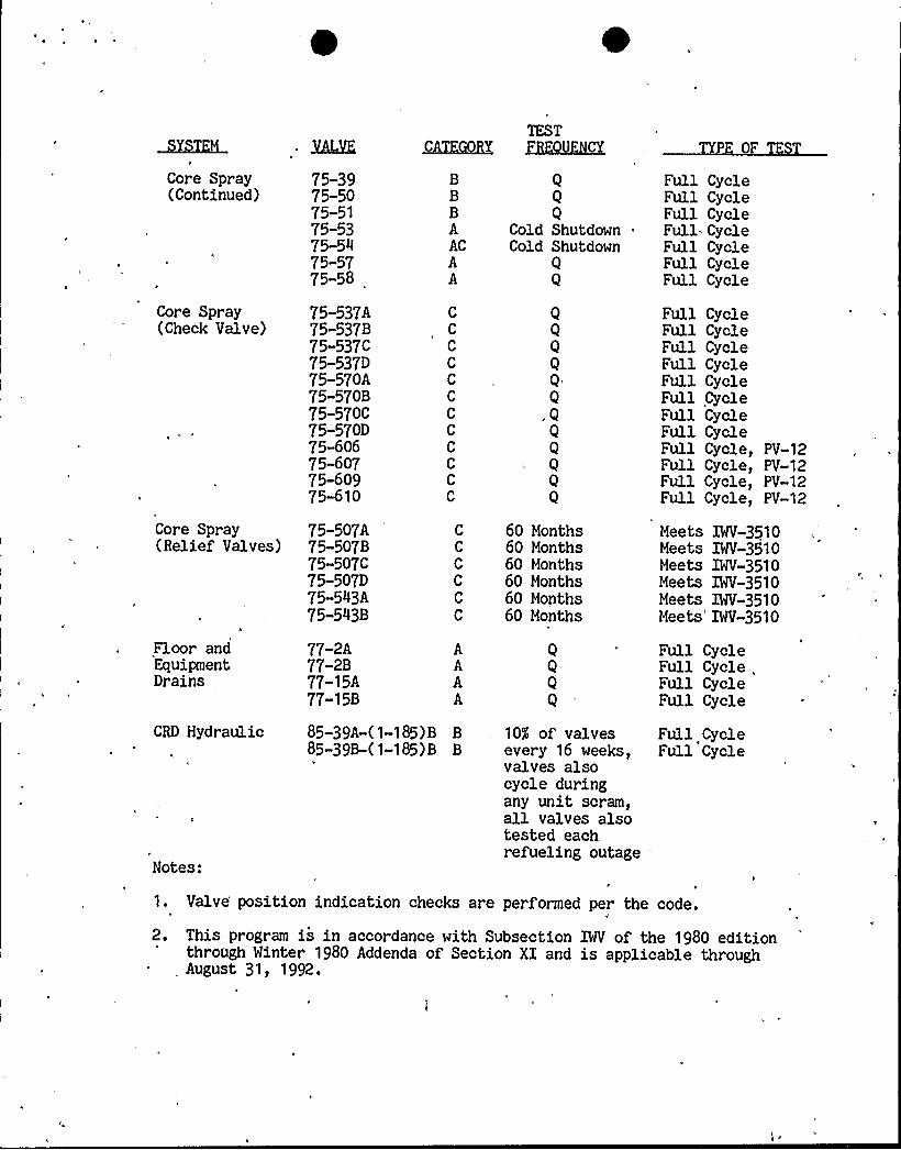
Core Spray(Continued)
75-39 B75-50 B75-51 B75-53 A75-54 AC75-57 A75-58 A
Q
Q
QCold Shutdown «
Cold ShutdownQ
Q
Full CycleFull CycleFull CycleFull CycleFull CycleFull CycleFull Cycle
Core Spray(Check Valve)
Core Spray(Relief Valves)
Floor andEquipmentDrains
75-537A75-537B75-537C75-537D75-570A75-570B75-570C75-570D75-60675-60775-60975-610
75-507A75-507B75-507C75-507D75-543A75-543B
77-2A77-2B77-15A77-15B
C
C
C
C
C
C
C
C
C
CC
C
C
C
C
C
C
C
AAAA
QQQ
Q
Q
Q
60 Months60 Mont;hs60 Mont;hs60 Mont;hs60 Months60 Months
Q
Q
Q
Q
Full CycleFull CycleFull CycleFull CycleFull CycleFull CycleFull CycleFull CycleFull Cycle, PV-12Full Cycle, PV-12Full Cycle, PV-12Full Cycle, PV-12
Meets IWV-3510Meets IWV-3510Meets IWV-3510Meets IWV-3510Meets IWV-3510Meets IWV-3510
Full CycleFull Cycle,Full CycleFull Cycle
CRD Hydraulic 85-39A-(1-185) B B85-39B-( 1-185) B B
1
10$ of valvesevery 16 weeks,valves alsocycle duringany unit scram,all valves alsotested eachrefueling outage
Full CycleFull Cycle
Notes:
1. Valve position indication checks are performed per the code,
2. This program is in accordance with Subsection IWV of the 1980 editionthrough Winter 1980 Addenda of Section XI and is applicable throughAugust 31, 1992.
'

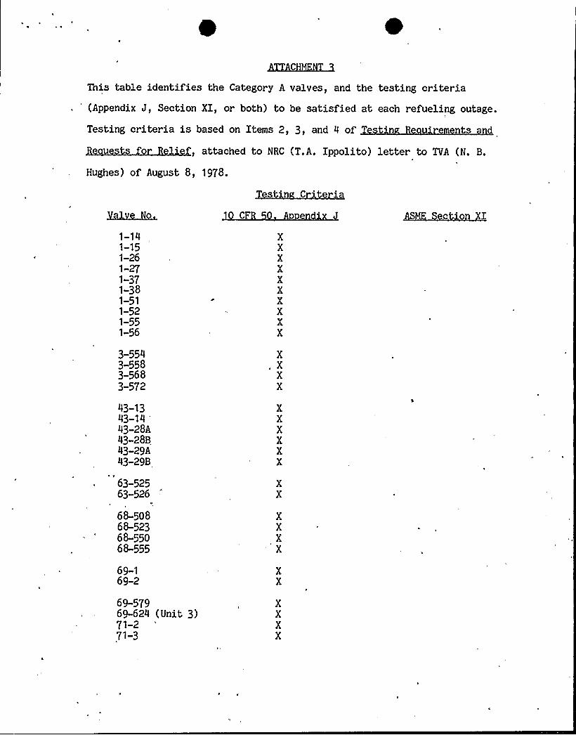
This table identifies the Category A valves, and the testing criteria, 'Appendix J, Section XI, or both) to be satisfied at each refueling outage.
Testing criteria is based on Items 2, 3, and 4 of t'n ' nts
, attached to NRC
Hughes) of August 8, 1978.
(T.A. Ippolito) letter to TVA (N. B.
1-141-151-261-271-371-381-511-521-551-56
3-5543-5583-5683-572
43-1343-14
'3-28A
43-28B43-29A43-29B
63-52563-526
68-5o868-52368-55O68-555
69-169-2
69-57969-624 (Unit 3)71-271-3
XXXXXXXXXX
XXXX
XXXXXX
XX
XXXX
XX
XXXX
ed'
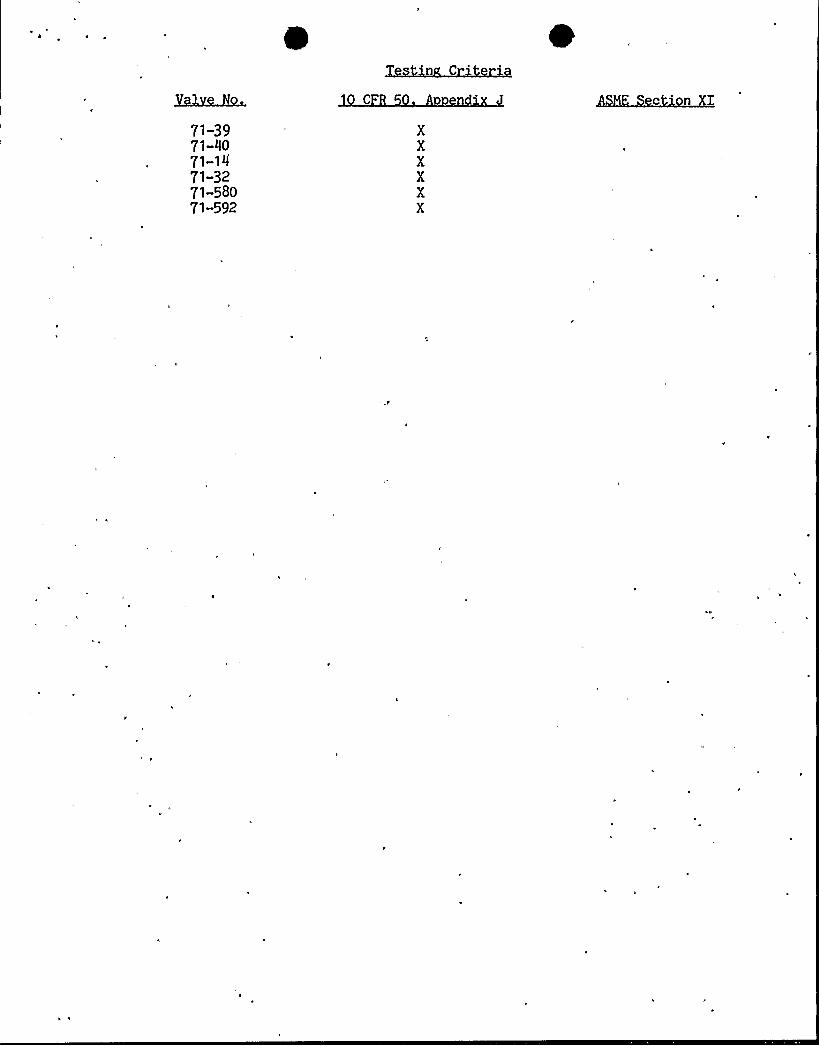
71-3971-4071-1471-3271-58071-592
0n C
XXXXXX
M c'n I
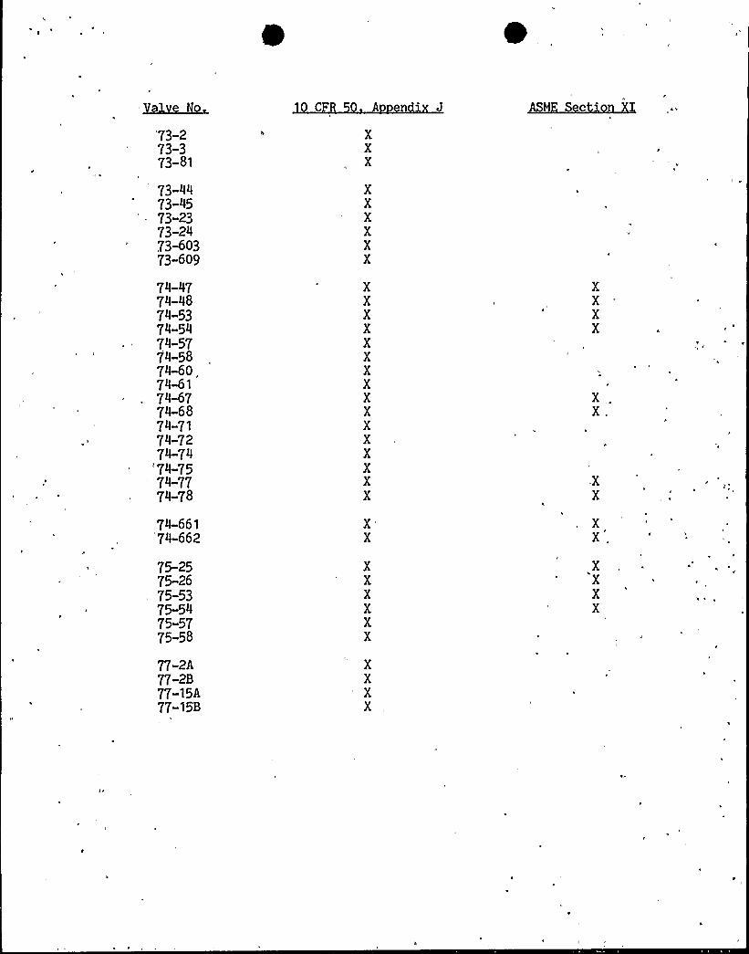
Yale.~~73-273-373-81
73-4473-4573-2373-2473-60373-609
74 4774-4874-5374-5474-5774-5874-60.74-6174-6774-6874-7174-7274 74
'74-75'4-77
74-78
74-661'74-662
75-2575-2675-5375-5475-5775«58
77-2A77-2B77-15A77-15B
XXX
XXXXXX
XXXXXXXXXXXXXXXX
X'
XXXXXX
XXXX
ASM c
XXXX
XX.
XX
XX,
XXXX

C M
REQUEST FOR RELIEF
LI P
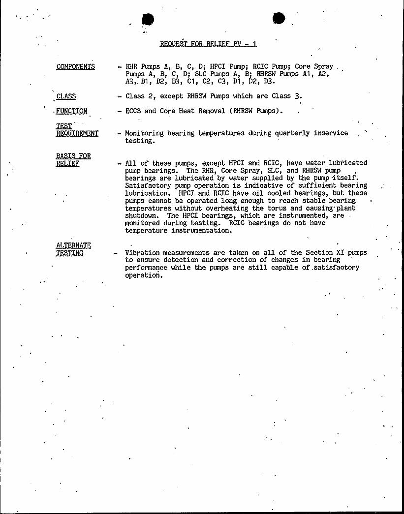
~CM Qg~S
~CA~)
QUQCCggg
- RHR Pumps A, B, C, D; HPCI Pump; RCIC Pump; Core Spray,Pumps A, B, C, D; SLC Pumps A, B; RHRSM Pumps A1, A2,A3). B1 ~ B2~ B3~ C1 ~ C2~ C3~ D1 ~ D2~ D3
- Class 2, except RHRSW Pumps which are Class 3.
- ECCS and Core Heat Removal (RHRSM Pumps).
- Monitoring bearing temperatures during quarterly inservicetesting.
Bh@MRE
LLZKBHKK
- All of these pumps, except HPCI and RCIC, have water lubricatedpump bearings. The RHR, Core Spray, SLC, and RHRSW pumpbearings are lubricated by water supplied by the pump itself.Satisfactory pump operation is indicative of sufficient bearinglubrication. HPCI and RCIC have oil cooled bearings, but thesepumps cannot be operated long enough to reach stable bearingtemperatures without overheating the torus and causing plantshutdown. The HPCI bearings, which are instrumented, aremonitored during testing. RCIC bearings do not havetemperature instrumentation.
4
Vibration measurements are taken on all of the Section XI pumpsto ensure detection and correction of changes in bearingperformance while the pumps are still capable of .satisfactoryoperation.

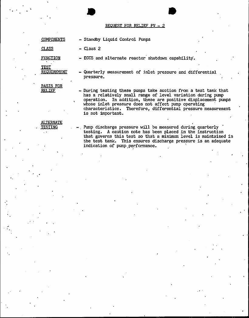
— Standby Liquid Control Pumps
- Class 2
— ECCS and alternate reactor shutdown capability'.
— Quarterly measurement of inlet pressure and differentialpressure.
- During testing these pumps take suction from a test tank thathas a relatively small range of level variation during pumpoperation. In addition, these are positive displacement pumpswhose inlet pressure does not affect pump operatingcharacteristics. Therefore, differential pressure measurementis not important.
—, Pump discharge pressure will be measured during quarterly
testing. A caution note has been placed in the instructionthat governs this test so that a minimum level is maintained inthe test tank. This ensures discharge pressure is an adequateindication of pump performance.

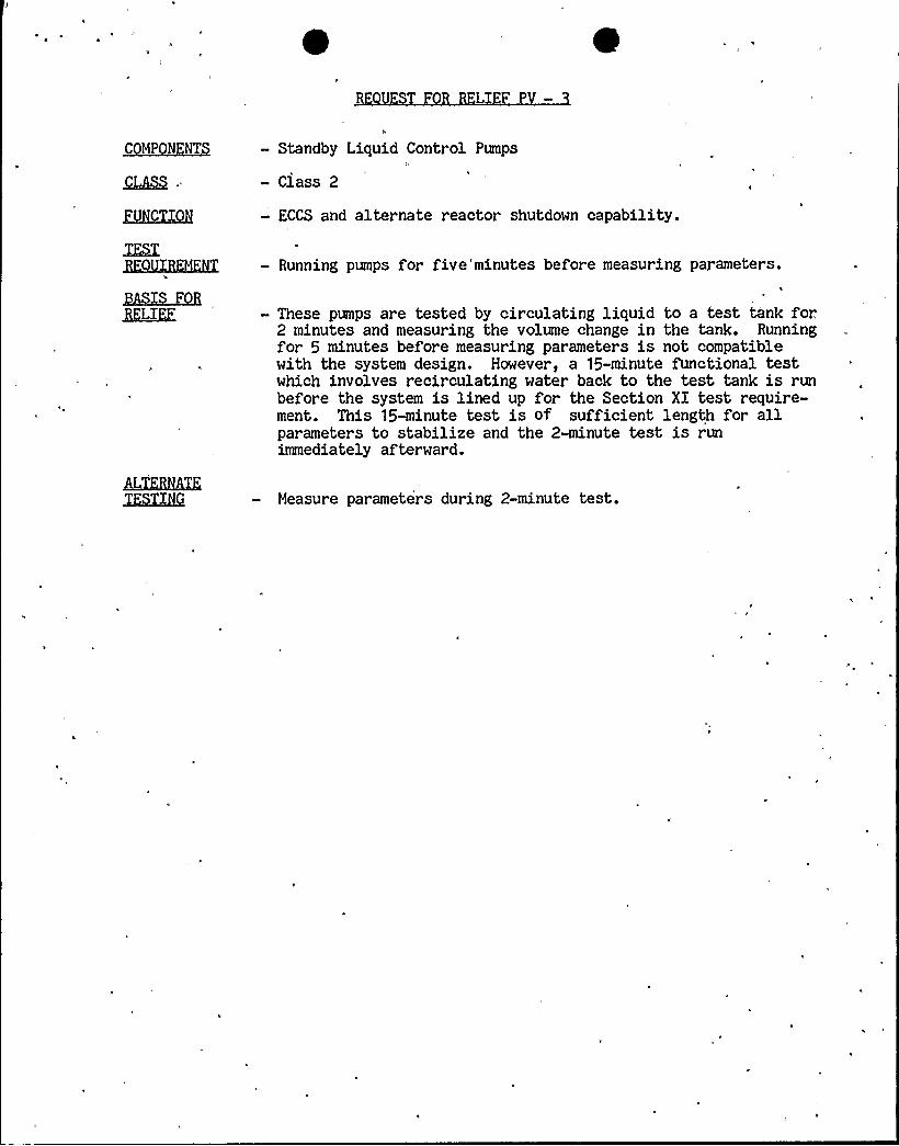
~C~P~NT — Standby Liquid Control Pumps
~CPS . - Class 2
f~CJQg - ECCS.and alternate reactor shutdown capability.
L
~3~/XK42Z
— Running pumps for five'minutes before measuring parameters.
- These pumps are tested by circulating liquid to a test tank for.2 minutes and measuring the volume change in the tank. Runningfor 5 minutes before measuring parameters is not compatiblewith the system design. However, a 15-minute functional testwhich involves recirculating water back to the test tank is runbefore the system is lined up for the Section XI test require-ment. This 15-minute test is of sufficient length for allparameters to stabilize and the 2-minute test is runimmediately afterward.
ZRXXK Measure parameters during 2-minute test.

C
4
IJ
L
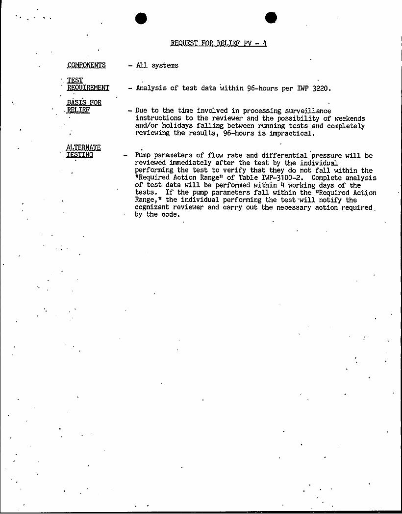
- All systems
- Analysis of test data within 96-hours per 1WP 3220.
B~~S. I~LI'F - Due to the time involved in processing surveillance
instructions to the reviewer and the possibility of weekendsand/or holidays falling between running tests and completelyreviewing the results, 96-hours is impractical.
Pump parameters of flow rate and differential pressure will bereviewed imnediately after the test by the individualperforming the test to verify that they do not fall within the"Required Action Range» of Table IWP-3100-2. Complete analysisof test data will be performed within 4 working days of thetests. Xf the pump parameters fall within the "Required ActionRange," the individual performing the test will notify thecognizant reviewer and carry out the necessary action required .
by the code.

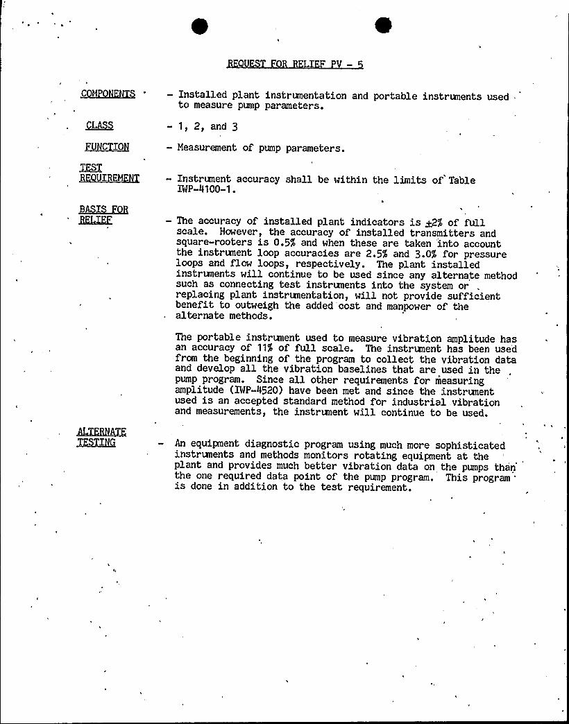
~C pgg5XQ — Installed plant instrumentation and portable instruments usedto measure pump parameters.
Q~>S
QJ~CI~O
-1,2,and3— Measurement of pump parameters.
— Instrunent accuracy shall be within the limits of'TableIMP-4100-1.
- The accuracy of installed plant indicators is ~2'5 of fullscale. However, the accuracy of installed transmitters andsquare-rooters is 0.5$ and when these are taken into accountthe instrument loop accuracies are 2.5$ and 3.0$ for pressureloops and flow loops, respectively. The plant installedinstr+vents will continue to be used since any alternate methodsuch as connecting test instrunents into the system or* .replacing plant instrumentation, will not provide sufficientbenefit to outweigh the added'cost and manpower of thealternate methods.
The portable instrument used to measure vibration amplitude hasan accuracy of 11% of full scale. The instrunent has been usedfrom the beginning of the program to collect the vibration dataand develop all the vibration baselines that are used in thepump program. Since all other requirements for measuringamplitude (XWP-4520) have been met and since the instrunentused is an accepted standard method for industrial, vibrationand measurements, the instrunent will continue to be used.
XFAGHG An equipment diagnostic program using much more sophisticatedinstrunents and methods monitors rotating equipment at theplant and provides much better vibration data on the pumps thanthe one required data point of the pump program. This programis done in addition to the test requirement.

S LI F
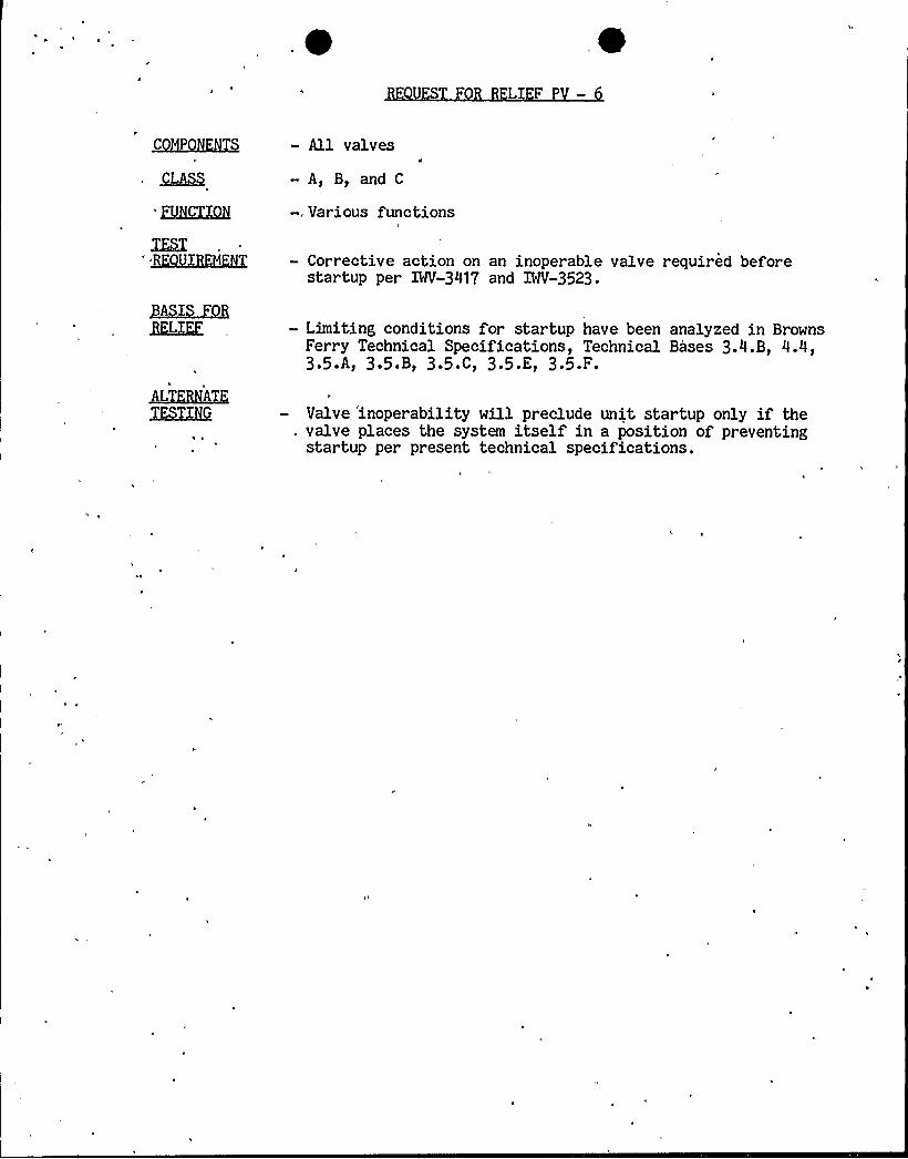
- All valves
- A, B, and C
-, Various functions
— Corrective action on an inoperable valve required beforestartup per Mf-3417 and IWV-3523.
- Limiting conditions for startup have been analyzed in BrownsFerry Technical Specifications, Technical Bases 3.4.B, 4.4,3 O'As 3'5 't 3 O'Ct 3'O'Es 3'5 F
Valve 'inoperability will preclude unit startup only if the. valve places the system itself in a position of preventing
startup per present technical specifications.

fl
L P
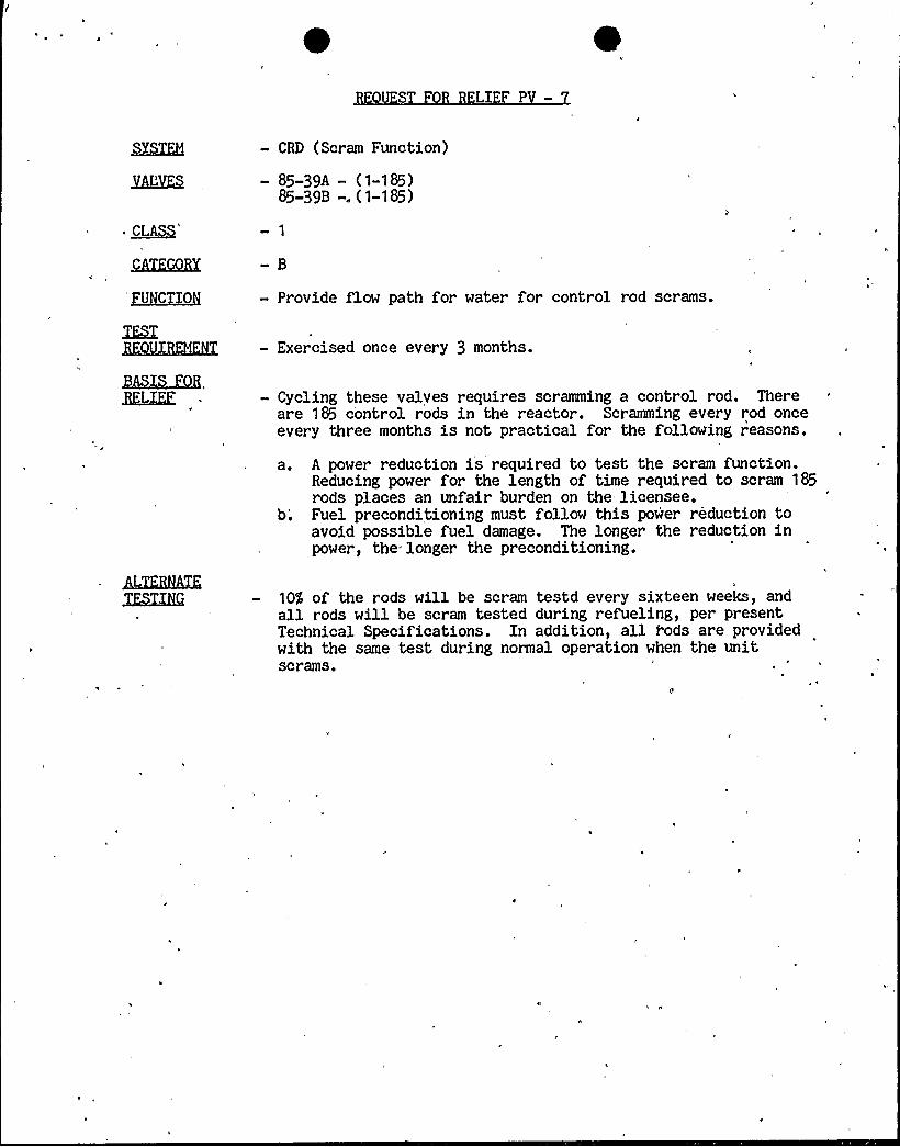
— CRD (Scram Function)
- 85-39A — (1-185)85-39B -. (1-185)
- Provide flow path for water for control rod scrams.
— Exercised once every 3 months.
— Cycling these valves requires scramming a control rod. Thereare 185 control rods in the reactor. Scramming every rod onceevery three months is not practical for the following reasons.
a. A power reduction is required to test the scram function.Reducing power for the length of time required to scram 185rods places an unfair burden on the licensee.b.'uel preconditioning must follow this power reduction toavoid possible fuel damage. The longer the reduction inpower, the longer the pr'econditioning.
10$ of the rods will be scram testd every sixteen weeks, andall rods will be scram tested during refueling, per presentTechnical Specifications. Xn addition, all rods are providedwith the same test during normal operation when the unitscrams.

lt
LlE
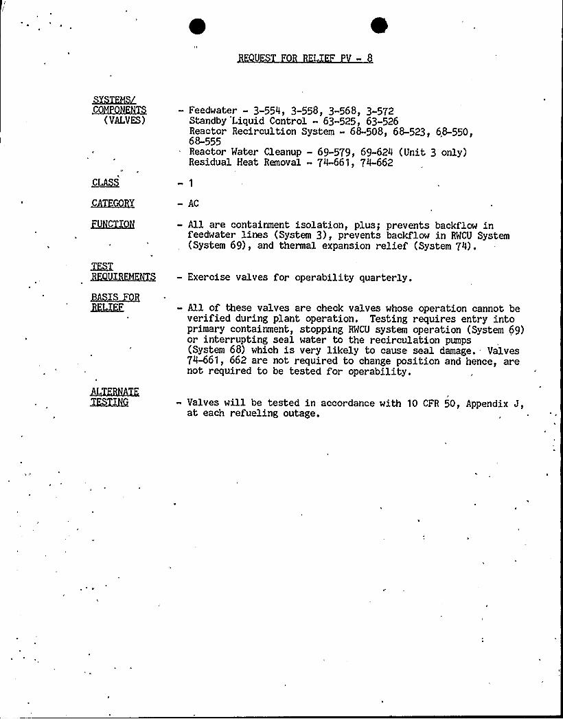
&5XF85LMCHRQHlBG5
(VALVES)— Feedwater — 3-554, 3-558, 3-568, 3 572
Standby Liquid Control - 63-525, 63-526Reactor Recircultion System — 68-508, 68-523, 68-550,68-555Reactor Water Cleanup - 69-579, 69-624 (Unit 3 only)Residual Heat Removal - 74-661, 74-662
- AC
ZEKTXQH - All are containment isolation, plus; prevents backflow infeedwater lines (System 3), prevents backflow in RWCU System(System 69), and thermal expansion relief (System 74).
~ASS QQjgL:gF
- Exercise valves for operability quarterly.
—All of these valves are check valves whose operation cannot beverified during plant operation. Testing requires entry intoprimary containment, stopping RWCU system operation (System 69)or inter rupting seal water to the recirculation pumps(System 68) which is very likely to cause seal damage. — Valves74-661, 662 are not required to change position and hence, arenot required to be tested for operability.
~BHbXI'.— Valves will be tested in accordance with 10 CFR 50, Appendix J,
at each refueling outage.
L
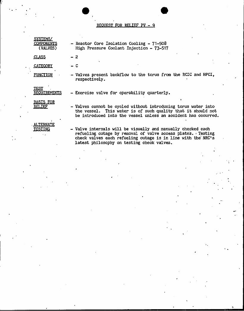
~XIZQLQZEQHKHX5
(VALVES)— Reactor Core Isolation Cooling - 71-508
High Pressure Coolant Injection —73-517
ZUK<UQH - Valves present backflow to the torus from the RCIC and HPCI,respectively.
- Valves cannot be cycled without introducing torus water intothe vessel. This water is of such quality that it should notbe introduced into the vessel unless an accident has occurred.
XLZ2583X— Valve internals will be visually and manually checked each
refueling outage by removal of valve access plates. Testingcheck valves each refueling outage is in line with the'RC'slatest philosophy on testing check valves.

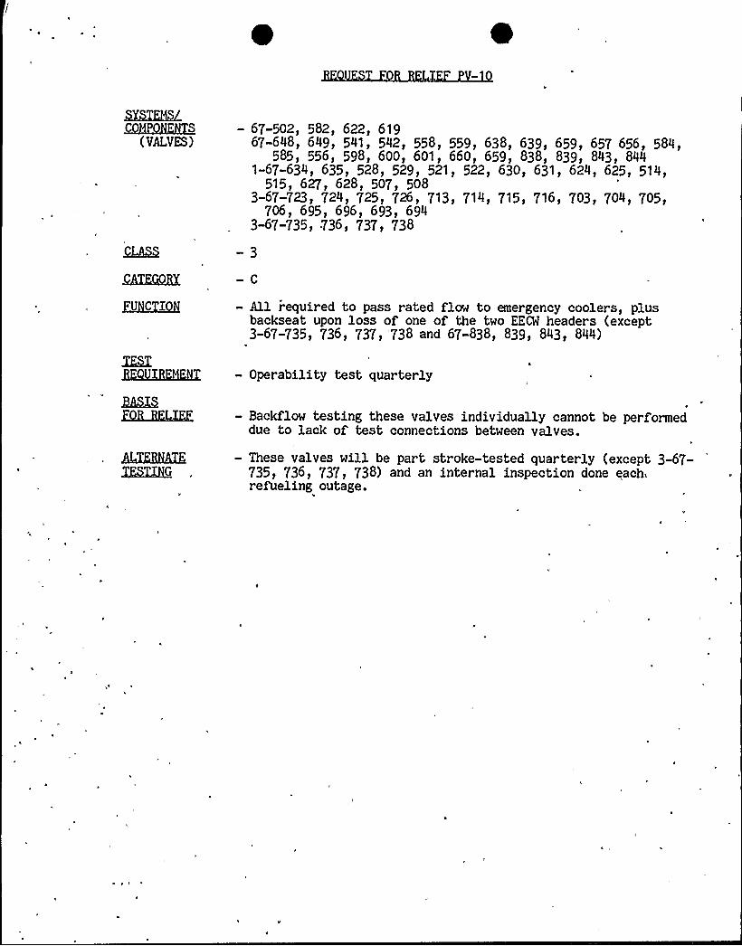
~Y~MMCKQKHXQ
(VALVES)- 67-502, 582, 622, 619
67-648, 649, 541, 542, 558, 559, 638, 639, 659, 657 656, 584,585, 556, 598, 600, 601, 660, 659, 838, 839, 843, 844
1-67-634, 635, 528, 529, 521, 522, 630, 631, 624, 625, 514,515, 627, 628, 507, 508
3-67-723, 724, 725, 726, 713, 714, 715, 716, 703, 704, 705,706, 695, 696, 693, 694
3-67-735, 736, 737, 738
j~UC 'Igg - All required to pass rated flow to emergency coolers, plusbackseat upon loss of one of the two EEL headers (except3-67-735, 736, 737, '738 and 67-838, 839, 843, 844)
— Operability test quarterly
WXQEKTK3XGX3¹
- Backflow testing these valves individually cannot be performeddue to lack of test connections between valves.
— These valves will be part stroke-tested quarterly (except 3-67-735, 736, 737, 738) and an internal inspection done each.refueling outage.
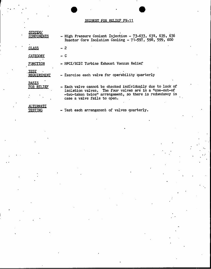
- High Pressure Coolant Injection —73-633, 634, 635, 636Reactor Core Isolation Cooling - 71-597, 598, 599) 600
- HPCI/RCIC Turbine Exhaust Vacuum Relief
— Exercise each valve for operability quarterly
- Each valve cannot be checked individually due to lack ofisolation valves. The four valves are in a "one-out-of-two-taken twice" arrangement, so there is redundancy incase a valve fails to open.
- Test each arrangement of valves quarterly.

It
'I
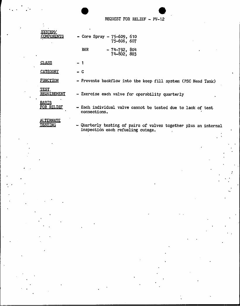
REQUEST FOR RELIEF - PV-12
MCHKHKHXQ - Core Spray - 75-609, 61075-606, 607
- 74-792, 80474-802, 803
XIX,
— Prevents backflow into the keep fillsystem (PSC Head Tank)
— Exercise each valve for operability quarterly
ZKU~IE
L4TQ5hXK3XSLQKi
- Each individual valve cannot be tested due to lack of testconnections.
— Quarterly testing of pairs of valves together plus an internalinspection each refueling outage.

'(
dl

ENCLOSURE 2RESPONSE TO NRC REQUEST FOR ADDITIONAL INFORMATION REGARDING
INSERVICE PUMP AND VALVE TESTING PROGRAM
BROWNS FERRY NUCLEAR PLANTUNITS 1, 2, AND 3
(Reference: NRC Letter from D. B. Vassallo to H. G. Parrisdated February 10, 1984)
NOTE: TVA's philosophy in writing the pump and valve testing program has beento include those systems and piping that carry water, steam, orradioactive material. We see no defined regulatory basis for the NRC
staff to increase the scope of testing in the inservice pump and valvetesting program, as is apparently the intent of questions 1 and 2. We,therefore, plan to respond only to those water, steam, or radioactivewaste-containing components in questions land 2, and request that oursubmittals be reviewed against currently defined regulatoryrequirements.
1. , NRC REQUEST
The pump portion of the IST program was reviewed to verify that all pumpsthat are important to safety are included in the program and aresubjected to the testing required by the ASME Code. In the staff'sjudgment there are additional systems wherein the associated pumps shouldbe in the program. These systems are:
Plant Service WaterPSC Head TankFuel Oil Transfer
Please justify the omission of the pumps in, these systems or revise theIST program to include them.
TVA RESPONSE
Plant Service Water Pumps--The plant service water system performs no safety-related function; hence, its pumps are not considered in the scope of SectionXI.
Pressure Suppression Chamber (PSC) Head Tank--The pumps in the Keep Fillsystem do not perform an active safety function in "keeping the core spray andRHR systems charged. The head tank water volume maintains these systemscharged at the required pressure. The head tank pumps maintain the proper
ahead tank level with occasional makeup to the head tank.
Fuel Oil Transfer —See note above.
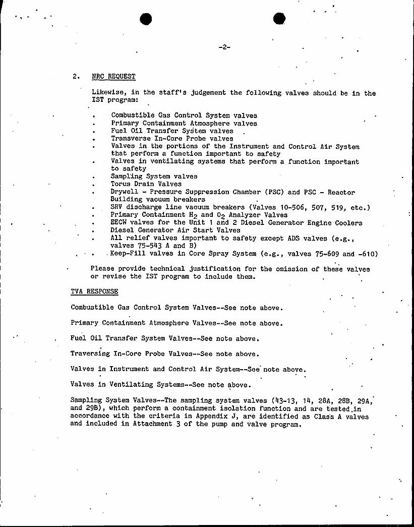
2. NRC REQUEST
Likewise, in the staff's judgement the following valves should be in theIST program:
Combustible Gas Control System valvesPrimary Containment Atmosphere valvesFuel Oil Transfer System valvesTransverse In-Core Probe valvesValves in the portions of the Instrument and Control Air Systemthat perform a function important to safetyValves in ventilating systems that perform a function importantto safetySampl'ing System valvesTorus Drain ValvesDrywell - Pressure Suppression Chamber (PSC) and PSC — ReactorBuilding vacuum breakersSRV discharge line vacuum br eakers (Valves 10-506, 507, 519, etc.)Primary Containment H2 and 02 Analyzer ValvesEECM valves for the Unit 1 and 2 Diesel Generator Engine CoolersDiesel Generator Air Start ValvesAll relief valves important to safety except ADS valves (e.g.,valves 75-543 A and B)
. Keep-Fill valves in Core Spray System (e.g., valves 75-609 and -610)
Please provide technical justification for the omission of these valvesor revise the IST program to include them.
TVA RESPONSE
Combustible Gas Control System Valves--See note above.I
Primary Containment Atmosphere Valves--See note above.
Fuel Oil Transfer System Valves--See note above.A
Traversing In-Core Probe Valves —See note above.
Valves in Instrument and Control Air System--See note above.I
Valves in Ventilating Systems--See note above.
Sampling System Valves —The sampling system valves (43-13, 14, 28A, 28B, 29A,and 29B), which perform a containment isolation function and are tested, inaccordance with the criteria in Appendix J, are identified as Clas's A valvesand included in Attachment 3 of the pump and valve program.

0 r
Torus Drain Valves —The torus drain valves (75-57, 58) that perform acontainment isolation function are included in the program.
Drywell —PSC and PSC-Reactor Building Vacuum Breakers--See note above.
SRV Discharge Line Vacuum Breakers--See note above.
Primary Containment H2 and 02 Analyzer Valves--See note above.
EECW Valves for units 1 and 2 Diesel Generator Engine Coolers--Thesevalves are tested per Section XI requirements but were inadvertently left outof the program submittal. They are included in the updated program.
Diesel Generator Air Start Valves--See note above.
All Relief Valves Important to Safety--We have reviewed the various safetysystems and have included those relief valves determined to be needed in ourprogram.
Keep Fill Valves in Core Spray and RHR Systems —These valves have beenincluded in the progr am as indicated in the valve listing with the conditionsnoted in Request for Relief PV-12.
3. NRC REQUEST
You requested relief for all pumps from the requirements of paragraphIWP-3220 that all pump test data be analyzed within 96 hours aftercompletion of the test. We agree that a delay of an additional daybefore pump test data is completely analyzed is not significant if thereis no delay in performing preliminary reviews of test data (includingvibration levels) immediately after the test, and any pumps whosemeasured test parameters fall within the Code "Required Action Range" areimmediately declared inoperable upon completion of the preliminaryreviews. Confirm that this is your intent.
TVA RESPONSE
A preliminary analysis is performed on pump test data (including vibration)immediately after the test. Any pump whose measured test parameters fallwithin the Code "Required Action Range" are immediately declared inoperable.We still need four working days for performing a complete analysis of pumpdata per relief request PV-4.

C
n
NRC REQUEST
You requested relief from paragraph IWV-3411 for valves 63-525 and 63-526and propose to exercise these valves during refueling to verify that theywill close. You must also verify that these valves will perform theirsafety-related function by passing design flow from the SLCS to the core.Please verify that this function will also be tested during refueling.
TVA RESPONSE
We verify that valves 63-525 and -526 will perform their safety-relatedfunction by passing design flow from the SLCS to the core during refueling.
5. NRC REQUEST
You requested relief from paragraph IWV-3411 for valves 74-661 and -662and propose to exercise these valves at each refueling because such atest entails entry into containment. We approve this request with thecondition that these valves also are tested during a cold shutdownwhenever the containment is de-inerted. Please pr ovide a commitment toperform tests during cold shutdown whenever possible (not to exceed thr eemonths frequency) or provide justification for not commiting to thisschedule.
TVA RESPONSE
We do not believe the benefits of testing of valves 74-661 and -662 duringcold shutdown warrant the increased risks to personnel safety. These risksinclude working and carrying test equipment in high radiation, hightemperature, and poorly accessible areas. These risks were discussed in-detail with NRC at the May 1982 meetings at Browns Ferry.
6. NRC REQUEST
From a review of your IST program, the staff finds that you have electedto leak test pressure-isolation valves to verify integrity. It is thestaff's position that,,when leak-rate testing is used to ve'rify theintegrity of pressure isolation valves, the leakage limits selected mustassure that valve sealing function has not excessively degraded. Thestaff does not consider relief valve capacity in setting pressureisolation valve 'leakage limits. The staff recommends a leakage limit for'pressure isolation valves of 0.5 gpm per nominal inch of valve size witha maximum leakage rate of 5 gpm. State whether you comply with thispostion. If you do not comply state and justify your acceptance testlimits.
TVA RESPONSE
We do not'comply with the staff recommended limits. Our Section XI acceptancetest limits for Pressure Isolation Valves (PIV) are based on system reliefvalve capacities, which are higher than the NRC staff recommended leakagelimits. However, these valves are also tested in accordance with Appendix Jand with reference leakage rate acceptance criteria that are more stringentthan the recommended limits. Rather than a basis of unnecessarily limitingvalues our acceptance criteria were chosen considering the design funct'ion ofthese valves and their integrated system responses with the closed loop safetysystems. In practice we easily meet the recommended limits while on the otherhand we do not limit ourselves to PIV leakage rates that would be less thanthose needed to protect the system integrity.
7. NRC REQUEST
Your IST program did not indicate performance of position indicatorverifications as required by the Code. Please verify that you meet thisCode requirement or )ustify your failure to do so.
TVA RESPONSE
We do meet the Code requirement of position indication verifications. Thisrequest was made previously in a letter from D. B. Vassallo to H. G.. Parrisdated January 17, 1983, and responded to in letter from L. M. Mills toH. R. Denton dated April 6, 1983.

N