Accepted for publication. DOI: 10.1109/MMM.2017.2680078...
32
56 June 2017 1527-3342/17©2017IEEE The COST IC1301 WiPE Team is a group of researchers in Europe focusing on the study of efficient wireless power transmission circuits, systems, and strategies specially tailored for batteryless systems. Digital Object Identifier 10.1109/MMM.2017.2680078 Date of publication: 8 May 2017 Europe and the Future for WPT T his article presents recent European-based contributions for wireless power transmis- sion (WPT), related to applications rang- ing from future Internet of Things (IoT) and fifth-generation (5G) systems to high- power electric vehicle charging. The contributors are all members of a European consortium on WPT, COST Action IC1301 (Table 1). WPT is the driving technology that will enable the next stage in the current consumer electronics revolution, including batteryless sensors, passive RF identification (RFID), passive wireless sen- sors, the IoT, and machine-to-machine solutions. These new devices can be powered by harvesting energy from the surroundings, including electromag- netic energy, or by designing specially tailored beamed wireless energy to power them. In this respect, we can further separate the WPT beam in the near field and the far field, where near field implies normally inductive or capacitive coupling and far field implies RF transmission. In Europe, a group of universities, research institutes, and companies have joined efforts to achieve advances in this area. This consortium, Wireless Power Transmission for Sustainable Electronics (or “WiPE”) and also known as COST Action IC1301, is a European Union framework for breakthrough science and technology. Here, we summarize the most recent developments in research by some of the members of this group. The article is divided into three major technology discussions: far-field (WPT) developments, near-field developments, and WPT applications. Within the far- field approaches, we discuss such issues as waveform analysis and modeling of RF–dc converters, propaga- tion modeling, and antennas specifically tailored for WPT schemes. For near-field approaches, we consider topics such as the optimized design of WPT induc- tive links and the modeling of these schemes, use of COST Action IC1301 Team Accepted for publication. DOI: 10.1109/MMM.2017.2680078 © 2017 IEEE. Personal use of this material is permitted. Permission from IEEE must be obtained for all other uses, in any current or future media, including reprinting/republishing this material for advertising or promotional purposes, creating new collective works, for resale or redistribution to servers or lists, or reuse of any copyrighted component of this work in other works.
Transcript of Accepted for publication. DOI: 10.1109/MMM.2017.2680078...

56 June 20171527-3342/17©2017IEEE
The COST IC1301 WiPE Team is a group of researchers in Europe focusing on the study of efficient wireless power transmission
circuits, systems, and strategies specially tailored for batteryless systems.
Digital Object Identifier 10.1109/MMM.2017.2680078
Date of publication: 8 May 2017
Europe and the Future for WPT
This article presents recent European-based
contributions for wireless power transmis-
sion (WPT), related to applications rang-
ing from future Internet of Things (IoT)
and fifth-generation (5G) systems to high-
power electric vehicle charging. The contributors are
all members of a European consortium on WPT, COST
Action IC1301 (Table 1). WPT is the driving technology
that will enable the next stage in the current consumer
electronics revolution, including batteryless sensors,
passive RF identification (RFID), passive wireless sen-
sors, the IoT, and machine-to-machine solutions.
These new devices can be powered by harvesting
energy from the surroundings, including electromag-
netic energy, or by designing specially tailored beamed
wireless energy to power them. In this respect, we can
further separate the WPT beam in the near field and the
far field, where near field implies normally inductive or
capacitive coupling and far field implies RF transmission.
In Europe, a group of universities, research institutes,
and companies have joined efforts to achieve advances in
this area. This consortium, Wireless Power Transmission
for Sustainable Electronics (or “WiPE”) and also known
as COST Action IC1301, is a European Union framework
for breakthrough science and technology.
Here, we summarize the most recent developments
in research by some of the members of this group.
The article is divided into three major technology
discussions: far-field (WPT) developments, near-field
developments, and WPT applications. Within the far-
field approaches, we discuss such issues as waveform
analysis and modeling of RF–dc converters, propaga-
tion modeling, and antennas specifically tailored for
WPT schemes. For near-field approaches, we consider
topics such as the optimized design of WPT induc-
tive links and the modeling of these schemes, use of
COST Action IC1301 Team
Accepted for publication. DOI: 10.1109/MMM.2017.2680078© 2017 IEEE. Personal use of this material is permitted. Permission from IEEE must be obtained for all other uses, in any currentor future media, including reprinting/republishing this material for advertising or promotional purposes, creating new collectiveworks, for resale or redistribution to servers or lists, or reuse of any copyrighted component of this work in other works.

June 2017 57
MAP—©ISTOCKPHOTO.COM/NOTVIPER,
TREE—©ISTOCKPHOTO.COM/ERHUI1979
electrical resonance for transferring power across
non-negligible distances, and underwater WPT. Finally,
we discuss several applications, including integra-
tion of WPT in buildings, the use of such systems in
wireless sensor networks (WSNs), embedding WPT
schemes in car textiles, and using RFID schemes for
improved efficiency.
Far-Field Deployments
Waveform Design for Maximizing RF–dc Conversion EfficiencyThe power transfer efficiency of WPT systems is one
of the most important parameters for the practical
application of the technology. The total efficiency of
a WPT system can be defined as
,T T L Rh h h h= (1)
where Th is the transmitter's dc–RF conversion effi-
ciency, Lh is the wireless link efficiency, and Rh is the
receiver's RF–dc conversion efficiency. The various
contributions to overall efficiency can be looked at
in more detail by considering the individual efficien-
cies corresponding to specific system blocks, such as
separating receiver efficiency into receive antenna effi-
ciency, rectifier efficiency, and dc–dc converter circuitry
efficiency contributions [1].

58 June 2017
TABLE 1. COST Action IC1301 contributors to this article.
Name Institution Name Institution
Nuno Borges Carvalho Instituto de Telecomunicacoes,
Universidade de Aveiro, Portugal
Apostolos Georgiadis Heriot-Watt University, Edinburgh,
Scotland, United Kingdom
Alessandra Costanzo University of Bologna, Italy
Nobby Stevens DraMCo Research Group, KU
Leuven, Belgium
Jan Kracek Czech Technical University in
Prague, Czech Republic
Luís Pessoa INESC TEC, Porto, Portugal
Luca Roselli University of Perugia, Italy
Fortunato Dualibe University of Mons, Belgium
Dominique Schreurs KU Leuven University, Belgium
Senol Mutlu Bogazici University, Istanbul, Turkey
Hendrik Rogier University of Ghent, Belgium
Huib Visser IMEC, Eindhoven, The Netherlands
Alexandru Takacs CNRS–LAAS, University of Toulouse, France
Paolo Rocca ELEDIA Research Center, University of Trento, Italy
Antonis Dimitriou Aristotle University of Thessaloniki, Greece
Jerzy Michalski SpaceForest Ltd., Poland
Zbynek Raida Brno University of Technology, Czech Republic
Smail Tedjini University Grenoble Alpes, Grenoble-INP, LCIS, Valence, France
Wout Joseph Ghent University/iMinds, Belgium
Yvan Duroc University of Lyon, France
John N. Sahalos University of Nicosia, Cyprus
Aggelos Bletsas Technical University of Crete, Greece
Theodoros Samaras Aristotle University of Thessaloniki, Greece
Sotiris Nikoletseas University of Patras, Greece, and Computer Technology Institute and Press “Diophantus,” Greece
Theofanis P. Raptis National Research Council, Institute of Informatics and Telematics, Pisa, Italy
Alírio Boaventura Universidade de Aveiro, Portugal
Ana Collado Heriot-Watt University, Edinburgh,
Scotland, United Kingdom
Riccardo Trevisan University of Bologna, Italy
Ben Minnaert DraMCo Research Group, KU
Leuven, Belgium
Milan Svanda Czech Technical University in
Prague, Czech Republic
Mário Pereira INESC TEC, Porto, Portugal
Mauro Mongiardo University of Perugia, Italy
Grigory Popov University of Mons, Belgium
Ning Pan KU Leuven University, Belgium
Herve Aubert CNRS–LAAS, University of Toulouse, France
Federico Viani ELEDIA Research Center, University of Trento, Italy
Stavroula Siachalou Aristotle University of Thessaloniki, Greece
Przemyslaw Kant SpaceForest Ltd., Poland
Gianfranco Andia Vera University Grenoble Alpes, Grenoble-INP, LCIS, Valence, France
Anastasis C. Polycarpou University of Nicosia, Cyprus
Pedro Cruz Universidade de Aveiro, Portugal
Franco Mastri University of Bologna, Italy
Milos Mazanek Czech Technical University in
Prague, Czech Republic
Hugo Santos INESC TEC, Porto, Portugal
Federico Alimenti University of Perugia, Italy
Hugo García-Vázquez University of Mons, Belgium
Sofie Pollin KU Leuven University, Belgium
Lorenzo Poli ELEDIA Research Center, University of Trento, Italy
Daniel Belo Universidade de Aveiro, Portugal
Diego Masotti University of Bologna, Italy
Jan Machac Czech Technical University in
Prague, Czech Republic
Vítor Tavares INESC TEC, Porto, Portugal
Paolo Mezzanotte University of Perugia, Italy
Papy Ndungidi University of Mons, Belgium
Giacomo Oliveri ELEDIA Research Center, University of Trento, Italy
Ricardo Fernandes Universidade de Aveiro, Portugal
Henrique Salgado INESC TEC, Porto, Portugal
Véronique Moeyaert University of Mons, Belgium
Andrea Massa ELEDIA Research Center, University of Trento, Italy
Ricardo Gonçalves Universidade de Aveiro, Portugal
Pedro Pinho Instituto de Telecomunicações, ISEL, Lisboa, Portugal
Giuseppina Monti University of Salento, Italy
Luciano Tarricone University of Salento, Italy
Marco Dionigi University of Salento, Italy
Peter Russer Technical University of Munchen, Germany
Johannes Russer Technical University of Munchen, Germany

June 2017 59
In an attempt to maximize the obtained efficiency,
recent literature has investigated the effect of the
transmitted signal waveforms on the RF–dc conver-
sion efficiency of rectifier circuits [2], [3] (Figure 1).
Initial results have shown that signals with peak-to-
average power ratio (PAPR) greater than 3 dB, which
corresponds to the PAPR of a pure sine wave, may
lead to a higher RF–dc conversion efficiency com-
pared to continuous wave (CW) signals. The effect of
different signals with a time-varying envelope, such
as chaotic waveforms [4] and various digitally modu-
lated signals and white noise [5]–[8], on RF–dc con-
version efficiency has been investigated. The results
show that it is possible to obtain better RF–dc conver-
sion efficiency compared to CW signals using signals
with a high PAPR. This can occur under certain aver-
age input-signal power levels as well as under certain
output-load conditions [9].
Additionally, the complementary cumulative dis-
tribution function of a signal reveals detailed infor-
mation about the number and frequency of signal
peak occurrences relative to its average value, and
signals with the same PAPR can lead to a differ-
ent RF–dc conversion efficiency [9]. Depending on
the application requirements that define a target
input average power and output load, one may syn-
thesize a signal waveform that maximizes the
RF–dc conversion efficiency, such as the so-called
multisine signals [10]. These signals are composed
of a sum of sine waves equally spaced in frequency
by ∆f and, usually, .f f∆ c% It can be shown that,
if all the subcarriers are added in phase, the resul-
tant time-domain signal exhibits a high PAPR value
that depends on the number of subcarriers and their
spectral weight distribution.
Another important consideration is that the enve-
lope is a periodic signal, with its period being in -
versely proportional to the frequency spacing .f∆^ h
A small value for this ∆f is desired to increase the
number of subcarriers in a limited bandwidth; how-
ever, a small ∆f leads to a very long envelope period,
decreasing the frequency at which the output filter-
ing capacitor is refreshed. Thus, multisine signals
should be carefully designed and must take into
account receiver characteristics such as the low-pass
filter time constant.
To increase the output filtering capacitor's refresh
rate, the work reported in [13]–[15] proposes a new
type of multisine signal. Using subcarriers that are
harmonically related ∆f f0=^ h, the envelope’s peak fre-
quency will be as high as the first subcarrier frequency,
reducing the constraints on the output low-pass filter's
time constant. Moreover, if the subcarriers are equally
weighted and in phase, the time-domain waveform is
asymmetric, with high positive peaks and low nega-
tive peaks. This asymmetric characteristic will boost
the efficiency not only in low-power environments due
to its high PAPR (such as conventional multisines) but
also in high power, when the diode is operating near
its breakdown (asymmetry reduces the peak-to-peak
swing). Because of the harmonic relation between car-
riers, several intermodulation products generated by
the rectifying process will contribute to a dc increase.
Another type of high PAPR waveform suitable for
WPT is proposed in [14]. Following radar fundamen-
tals, a linear frequency-modulated signal known as a
chirp signal is considered. If an up-chirp is correlated
with a down-chirp (a pulse-compression technique),
a pulse will be created, and its high PAPR and occur-
rence can be controlled with the basic chirp band-
width and frequency sweep time. The occurrence
of the pulse should be carefully controlled to avoid
a large ripple in the output, which in turn reduces
the output dc voltage. Due to its very high PAPR, this
kind of signal will drive the rectifying element into
its breakdown zone for lower input power when com-
pared with other excitations.
Finally, we should emphasize that the absolute
value of the RF–dc conversion efficiency strongly
depends on the nonlinear device and circuit architec-
ture characteristics of the rectifier, and it is possible
to improve the obtained efficiency by combining
These new devices can be powered by harvesting energy from the surroundings, including electromagnetic energy, or by designing specially tailored beamed wireless energy to power them.
25
20
15
Effic
iency (
%)
10
5
0–20 –15 –10
Pin (dBm)–5 0 4
Radar Compressed Pulse
929–949 MHz/Sweep Time = 0.28 µs
CW at 939 MHz
Multisine, N = 2, 938 and 940 MHz
Harmonically Related Multisine, N = 2,
939 and 1,878 MHz
Figure 1. A comparison of RF–dc conversion efficiency with different waveforms.

60 June 2017
WPT with other energy harvesting technologies such
as mechanical [11] or thermal [12].
Modeling Aspects of RF–dc ConversionAfter realizing the advantage of multisine excitation
for WPT, it becomes necessary to understand the impact
of various design parameters such as bandwidth or the
number of tones. In [16], the multisine signal is rep-
resented as an amplitude-modulated signal (2) with
bandwidth B (3):
,cosx t A f t2m cr=^ ^h h (2)
.fB N t $T= (3)
Here, fc is the carrier frequency, Am is the envelope of
the signal, Nt represents the number of tones, and fT
their frequency spacing.
Given this signal representation, the analytical RF
power-conversion efficiency (PCE) /PCE V R pDC L in$=^ ^ hh
is calculated by relating the bandwidth and envelope
amplitudes to the output dc voltage VDC for different sig-
nals by applying
. .dtV V A Pdf ADC
N
m m0
out
period
$= 8 ^ ^h h (4)
Pdf Am^ h is the probability distribution function
of the envelope amplitude as triggered by the multi-
sines. ,VDC as described in (4), is the average function
of instantaneous output voltage Vout depending on
different ,Am reflecting the input-power-dependent
performance of rectifiers.
The input signal to the rectifier x ti ^ h is the multi-
sine signal ,x t^ h where parts of the signal are reflected
due to circuit mismatches that depend on the B of the
input signal .x t^ h As a result, B and circuit mismatches
also change .Pdf Am^ h By studying the reflection coef-
ficient S11 of the given rectifier, we can select the opti-
mal bandwidth of the signal. For the circuit used in
this analysis, the optimal B is 2 MHz, as shown in Fig-
ure 2. Knowing that the number of tones Nt influences
both the B and amplitude shape Pdf A ,m i^ h of ,x tin ^ h
the optimal Nt can be determined using the mathe-
matical model described earlier.
The analytical results are confirmed by measure-
ments. The measurement configuration is shown in
Figure 3. Depending on the rectifier used in this exper-
iment, the PCE of the multisine-based WPT system can
be improved 25.1% compared to a CW excitation WPT for
−5-dBm input power, as shown in Figure 4.
Link Modeling and Integrated Antenna Design Strategies for Ultrawide-Band WPTThe IoT vision requires the deployment of vast amounts
of wireless nodes that are invisibly integrated into their
environment. Important challenges when designing
such nodes include ensuring sufficient autonomy to
guarantee reliable wireless communication over sus-
tained periods of time, while avoiding interference with
other devices. For compactness and eco-friendliness,
the use of large batteries should be avoided, and small
energy buffers such as super-capacitors should be pre-
ferred. Therefore, the device should be able to continu-
ously harvest energy from multiple sources available in
its environment. Intentional WPT may supplement the
powering process, or it may act as the only power sup-
ply in cases where all energy sources are scarce.
Interference issues and health risks associated with
the transmission of RF power beams may be avoided
by lowering the power spectral density. This is achieved
by spreading out the radiated power over a large fre-
quency band. Such a technique is already applied
Spectrum
Analyzer
Waveform
Generator
Voltage
Meter Power
Splitter
Figure 3. The measurement configuration for the tests described in the “Modeling Aspects of RF–dc Conversion” section.
Figure 2. VDC versus B, with RF signal input power of −5 dBm and 1.6 GHz carrier frequency.
9
8.5
8
2 4 6 8B (MHz)
VD
C (
mV
)
The power transfer efficiency of WPT systems is one of the most important parameters for the practical application of the technology.

June 2017 61
in ultrawide-band (UWB) communication, which is
allowed by the U.S. Federal Communications Com-
mission in the 3.1–10.3-GHz frequency band, provided
that the power spectral density remains smaller than
−41.3 dBm/MHz [17]. Similarly, the European Com-
mission (EC) has issued an EC decision allowing UWB
devices to use the 3.4–4.8- and 6.0–8.5-GHz bands with
the same maximum power spectral density, provided
that signals in the lower frequency band meet a low
duty-cycle restriction [18].
An important challenge for implementing such
UWB WPT in an IoT setting is that wireless nodes will
operate in a diverse range of deployment scenarios.
In most of them, many objects will be present in close
proximity to the receive antenna, causing potential
antenna detuning and reduction in radiation effi-
ciency. Moreover, the WPT wireless channel will differ
significantly from free space, as important shadowing
and multipath fading effects may occur. Therefore,
we have developed robust high-performance UWB
antennas and a dedicated block model that describes
all antenna and multipath propagation characteristics
that play a role in the complete wireless power link.
Both components enable the development and opti-
mization of stable UWB WPT links, operating in all
kinds of adverse deployment conditions. They enable
optimal exploitation of the large bandwidth through the
design of suitable waveforms, and they maximize WPT
while still respecting safety and health regulations.
Designing UWB antennas for the IoT paradigm is
highly complex. Deployment conditions require anten-
nas featuring a high antenna/environment isolation
for stable radiation. A low-profile, compact, and adapt-
able geometry that also conforms to the environment is
needed for invisible integration. Such antenna topologies
typically exhibit narrow-band radiation characteristics.
Recently, the implementation of substrate integrated
waveguide (SIW) technology in novel antenna materi-
als such as textile fabrics [19], paper, and cork [20] has
resulted in novel designs that reconcile all these require-
ments. By confining the electromagnetic fields by rows
of vias, components operate in isolation from their envi-
ronment, yielding a performance almost as stable as in
waveguide components [21]. For cavity-backed SIW slot
antennas, such as the antenna array shown in Figure 5,
only the slot radiates, thus enabling the deployment of
active circuitry directly underneath and energy har-
vesters on top of the cavity [22]. The complete antenna
area may be reused, apart from the radiating slot.
UWB operation is implemented by exciting multiple cav-
ity modes at carefully selected frequencies within the
operational bandwidth. Moreover, the antenna may
be miniaturized by exploiting half-mode and quarter-
mode principles.
Besides using a suitably designed antenna, the
optimization of the WPT channel requires that the
wireless channel characteristics and the deployment
characteristics of the antennas be fully taken into
account. Indeed, multipath propagation will affect the
power transfer, causing fading and shadowing effects
as experienced in conventional communication chan-
nels. Furthermore, because they are in the reactive near
field, objects in direct proximity to the transmit and/
or receive antennas will modify the channel’s power
transfer characteristics. Therefore, they should also be
included in a global WPT model applied to optimize
the power transfer.
As a computer-aided-engineering tool for UWB
WPT system designers, we have developed a modeling
framework [23] for WPT over UWB links in multipath
propagation environments. Although the concatenated
black-box model is specifically implemented for WPT
1.80010
5
0
1.600
1.400
1.200
10 20 30 40 50Nt
2 64 8 10 12Nt
(a) (b)
VD
C (
mV
)
VD
C (
mV
)
Figure 4. VDC behavior with increasing Nt; the RF signal input power is −5 dBm, and carrier frequency is 1.6 GHz. (a) The Matlab simulation result and (b) the measure-ment result.
Figure 5. A UWB SIW textile antenna array for WPT.
Multisine signals should be carefully designed and must take into account receiver characteristics such as the low-pass filter time constant.
62 June 2017
in the vicinity of the human body, the framework may
also be successfully applied to other typical IoT config-
urations. The modularity of the model makes it easy to
replace the measured or simulated black-box descrip-
tions of the antennas and the channel by those that are
pertinent to the setup at hand. Proximity effects caused
by objects in the reactive near field of the antenna may
easily be accounted for by incorporating the embed-
ded active-element antenna pattern and the detuned
antenna impedance in the black-box description of the
antenna under study. For the application of this model
to body-centric WPT, we refer to [24]. By relying on a
fast-multipole-based expansion of the channel [24], the
Friis-based path-loss black box may be extended such
that the channel model also applies to the radiative
near field.
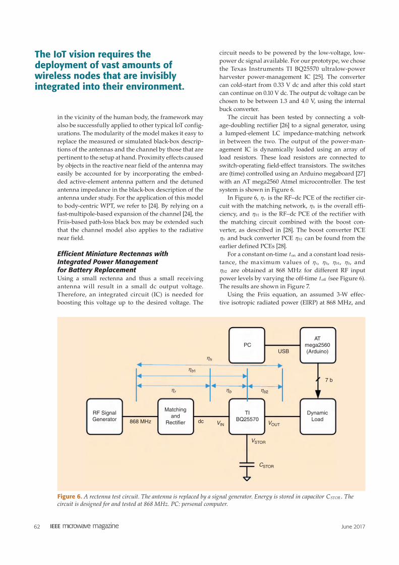
Efficient Miniature Rectennas with Integrated Power Management for Battery ReplacementUsing a small rectenna and thus a small receiving
antenna will result in a small dc output voltage.
Therefore, an integrated circuit (IC) is needed for
boosting this voltage up to the desired voltage. The
circuit needs to be powered by the low-voltage, low-
power dc signal available. For our prototype, we chose
the Texas Instruments TI BQ25570 ultralow-power
harvester power-management IC [25]. The converter
can cold-start from 0.33 V dc and after this cold start
can continue on 0.10 V dc. The output dc voltage can be
chosen to be between 1.3 and 4.0 V, using the internal
buck converter.
The circuit has been tested by connecting a volt-
age-doubling rectifier [26] to a signal generator, using
a lumped-element LC impedance-matching network
in between the two. The output of the power-man-
agement IC is dynamically loaded using an array of
load resistors. These load resistors are connected to
switch-operating field-effect transistors. The switches
are (time) controlled using an Arduino megaboard [27]
with an AT mega2560 Atmel microcontroller. The test
system is shown in Figure 6.
In Figure 6, rh is the RF–dc PCE of the rectifier cir-
cuit with the matching network, hh is the overall effi-
ciency, and b1h is the RF–dc PCE of the rectifier with
the matching circuit combined with the boost con-
verter, as described in [28]. The boost converter PCE
bh and buck converter PCE b2h can be found from the
earlier defined PCEs [28].
For a constant on-time ton and a constant load resis-
tance, the maximum values of ,rh ,hh ,b1h ,bh and
b2h are obtained at 868 MHz for different RF input
power levels by varying the off-time toff (see Figure 6).
The results are shown in Figure 7.
Using the Friis equation, an assumed 3-W effec-
tive isotropic radiated power (EIRP) at 868 MHz, and
PCUSB
AT
mega2560
(Arduino)
7 b
Dynamic
Load
VSTOR
CSTOR
VOUTdc VIN
TI
BQ25570
Matching
and
Rectifier
RF Signal
Generator 868 MHz
ηh
ηb1
ηb2ηbηr
Figure 6. A rectenna test circuit. The antenna is replaced by a signal generator. Energy is stored in capacitor .CSTOR The circuit is designed for and tested at 868 MHz. PC: personal computer.
The IoT vision requires the deployment of vast amounts of wireless nodes that are invisibly integrated into their environment.

June 2017 63
the results shown in Figure 8, the average obtained dc
power has been calculated as a function of distance for
two receive antennas (1- and 6.1-dBi gain). The results
are shown in Figure 9.
From Figure 7 and Figure 9, we can conclude that with
a 6.1-dBi receive antenna we can get W30 n of continuous
dc power up to a 10-m distance or 60 mW for 40 ms every
2 min up to the same distance.
For a prototype, a 2-dBi miniaturized 915-MHz
antenna [29], complex-conjugately matched to the
rectifier, has been combined with the TI BQ22570 IC,
resulting in a 10-cm × 6-cm wireless battery, as shown
in Figure 10.
Compact Microwave Rectenna for Satellite Health MonitoringTo provide reliable high-bit-rate broadcasting links, high-
gain microwave antennas are used on broadcasting sat-
ellites. These antennas are located on panels positioned
on the external surfaces of the satellite and are subject
to spillover losses. In some areas of the antenna pan-
els, the electric field generated by the spillover losses of
microwave antennas may reach the following maximum
levels (effective values) [30]: 40 V/m in C-band, 49.5 V/m
in X-band, 106 V/m in Ku-band, and 127 V/m in K-band.
These electric field levels are unusual for terrestrial appli-
cations, but they can occur on satellites when data links
are functional. These (residual) electromagnetic fields
can be harvested to power-autonomous wireless sensors
for structural health monitoring of the satellite. The radi-
ated power of microwave antennas is almost constant;
consequently, the dc power regulatory circuits should be
minimal for such harvesting systems.
To demonstrate the proof of concept and feasibil-
ity of such harvesters, several rectennas were devel-
oped by the research group at CNRS-LAAS Toulouse
[31] in the framework of research grants funded by
CNES (the French space agency). The goal was to
Pout
0
Time
T
ton toff
Figure 7. A time diagram of drawing dc power from the circuit shown in Figure 6. T is the period. During ,ton a dc power Pout is drawn. During ,toff no power is drawn.
100
80
60
40
Effic
iencyη
(%
)
20
0–15 –10 –5 0 5 10
RF Input Power (dBm)
RectifierBoost Convertor
Rectifier + BoostBuck ConvertorTotal
Figure 8. Maximum PCEs as a function of RF input power level for the setup shown in Figure 6.
104
103
102
101
Availa
ble
Pow
er
(µW
)
100
10–1
0 2 4 6 8 1210
Distance (m)
1.0-dBi Antenna
6.1-dBi Antenna
Figure 9. The average obtained dc power versus free line-of-sight distance for two antennas. The solid lines represent the results for the circuit described in Figure 6. The dashed lines represent the results for a commercially available radiative WPT system tested for the same EIRP but for a frequency of 915 MHz.
(b)(a)
Figure 10. A printed circuit board (PCB)-integrated rectenna and its power management: (a) the PCB and (b) the system powering a temperature sensor with display.

64 June 2017
develop compact, high-efficiency rectennas providing
dc power in the milliwatt range. Based on innovative
antenna topologies, the cross-dipole antenna (CDA)
and CDA array (CDAA), we recently proposed com-
pact coplanar stripline-supported rectennas. Figure 11
shows the CDA rectenna topology, while the CDAA
rectenna is depicted in Figure 12.
CDA rectennas use only the top side of the PCB.
In the case of a CDAA, the antenna and the diode are
located on the top side of the PCB, while the short-
ing RF capacitor and the load are located on the bot-
tom side. The conjugate matching condition (between
antenna and rectifier) is achieved without the use of
a dedicated matching circuit but by properly control-
ling the input impedance of the antenna (CDA or
CDAA) and the input impedance of the rectifier. A
reflector plane, positioned below the rectennas at an
approximately quarter-wavelength distance, is used to
increase the antenna gain and thus improve the overall
performance of the CDA and CDAA rectennas.
The efficiency h (in %) of the rectenna can be com-
puted using the following [32]:
S A
P100
G
DC1
$
$h = (5)
,S A
P
S G
P100
4100DC
R
DC2 2
eff$
$
$ $
$ $
$hm
r= = (6)
where PDC is the harvested dc power, S is the incident
electromagnetic power density, AG denotes the area of
the radiating surface, Aeff is the antenna effective area,
GR is the gain of the antenna, and m is the wavelength
of the illuminating electromagnetic wave. The effi-
ciency 1h can be viewed as a “worst-case” definition,
because A Aeff G# for passive antennas.
Experimental results [33] show that 1.15 mW of dc
power can be harvested in the Ku-band (14.7 GHz)
using a compact CDAA rectenna illuminated by an
electric field of 60 V/m ( W/cm ).S 955 2+ n This ultra-
compact Ku-band CDAA rectenna (2.5 cm2 or 0.6
square wavelength) exhibits a conversion efficiency
of %( %).48 661 2h h= = A low-cost silicon Schottky
diode (SMS201 from Aeroflex/Metelics) in a molded
plastic (dual flat no-lead) package was used for this
design. A manufactured K-band (18.8 GHz) CDA
rectenna (using a gallium arsenide Schottky diode
MZBD-9161 from Aeroflex/Metelics) [30] demon-
strated that a dc power of 1.28 mW can be harvested
when an electric field of 91 V/m ( . /cm )S 2 2 mW 2+
illuminates the rectenna. The efficiency of this CDA
rectenna is %.481h = We note that CDA and CDAA
rectenna topologies can be easily adapted for other
operating frequencies. The experimental results ob -
tained with these rectennas demonstrate that imple-
menting autonomous wireless sensors can be a feasible
solution for the structural health monitoring of satel-
lite antenna panels.
Design and Optimization of Phased Arrays for Long-Range WPTThe design of phased-array antennas is key to guar-
anteeing high-efficiency, reliable, and cost-effective
long-range WPT system deployments [34]. Unlike com-
munications and radar applications, the goal of a WPT
system is to maximize end-to-end power transfer effi-
ciency. Therefore, unconventional constraints need
to be taken into account and, consequently, uncon-
ventional design methodologies explored [34a]. For
long-range WPT systems, the transmitting array must
focus power within a narrow, angular sector toward
the receiving station or stations, while the receiving
(i.e., rectenna) array must be able to convert the larg-
est amount of RF impinging power. In this framework,
several research projects have been carried out over
the last few years, spurred by the diffusion of electrical
PCB Top
PCB Bottom
Diode
Capacitor
Load
Figure 12. The top and bottom layers of the CDAA rectenna and (inset) a photo of the manufactured prototype.
DiodeCapacitor
Load
Figure 11. The top view of the CDA rectenna and (inset) a photo of the manufactured prototype.

June 2017 65
autonomous systems (e.g., drones, cars, and high-alti-
tude platforms) and growing interest in the very chal-
lenging and fascinating application of space-based
solar power (SBSP), which is aimed at guaranteeing a
continuous feeding of the Earth with renewable and
clean energy [35]. Novel methodologies for the design
of arrays for long-range WPT and the optimization of
their degrees of freedom (DoFs) have been introduced
aimed at
defining the best array configurations (e.g., positions
and excitation weights of the array elements) to
maximize 1) the beam collection efficiency (BCE),
i.e., the ratio of the power transmitted toward
the receiving/target area and the total radiated
power, in the case of transmitting arrays or 2) the
efficiency of the microwave power collection in
the case of rectenna arrays
synthesizing simplified array architectures to
reduce antenna complexity and cost as well as
to make the hardware/software implementa-
tion easier.
As for the optimal design of transmitting planar
phased arrays, a strategy for synthesizing the opti-
mal tapering of the amplitude weights that guaran-
tees maximum BCE performance in cases of arbitrary
transmitting planar ap ertures and target areas has been
proposed in [36]. The approach, based on the solu-
tion of a generalized eigenvalue problem by means of
a deterministic method, has allowed study of the theo-
retical limits of the power transmission efficiency of
WPT planar phased arrays. Useful guidelines on the
design of the transmitting array configuration have
been reported to achieve high values of BCE (close to
100%), whatever the shape of the transmitter and/or
receiving area. As a representative example, Figure 13(a)
shows the power pattern generated by a planar array
consisting of 20 × 20 elements, the excitation amplitudes
of which [Figure 13(b)] have been synthesized by means
of the method described in [36] to achieve a BCE per-
formance of 99.96%.
Work regarding receiving antennas for long-range
WPT has focused on studying and defining innova-
tive rectenna arrays for SBSP systems to be used in
the ground station. Starting from the key observation
that the dc currents at the output of the rectifying
circuitry used for each individual element or cluster
of elements have no phase term (and, consequently,
their coherent sum is not needed), the position of
the elements has been properly optimized to avoid
superpositions and shadowing effects that would
reduce end-to-end WPT efficiency [37]. Moreover,
because a portion of the microwave power arriving
on the rectenna array is unavoidably backscattered,
the DoFs of the element positions have been defined
such that the reradiated field is focused toward a
mirror that can redirect the power toward the rec-
tenna array [37].
Innovative array architectures to reduce the com-
plexity and weight of the transmitting arrays have
been studied, as well. Two strategies, in particular,
have been investigated: 1) clustering the elements
into subarrays to reduce the number of amplifiers
and phase shifters/delay units and 2) using irregu-
lar (e.g., sparse) array layouts to minimize the num-
ber of radiating elements [38]. Optimization of the
arrays' DoFs has been carried out by means of ad hoc
design methodologies. As for clustered arrays, an
excitation matching approach based on the contigu-
ous partition method (CPM) [39] has been exploited
to define the clustering configuration and the sub-
array excitations so as to obtain a pattern as close
as possible to the one having optimal BCE [36]. The
availability of the optimal excitations has enabled,
through the CPM, the effective synthesis of very
large phased arrays, not feasible when using con-
ventional design methods.
The design of sparse planar arrays matching a desir-
ed reference pattern has been addressed by means of
an innovative synthesis method based on Bayesian
compressive sensing (BCS) [40]. The key advantage
of the BCS methodology is that it allows light-trans-
mitting arrays with a minimum number of elements.
Preliminary results have shown that BCS-designed
array configurations with a 35% reduction in the total
number of elements guarantee a BCE-optimal power
pattern by considering the same antenna aperture.
Further studies in this area of research will consider
the design of arrays with more complex geometries
(e.g., conformal) as well as the use of simpler feeding
networks characterized, for example, by isophoric (i.e.,
uniform) amplitude weights.
Far-Field Channel Modeling for WPT SystemsWell-designed, efficient WPT systems often fail in the
application field due to undesired effects caused by
the propagation channel. The power limitations of
WPT systems, imposed by the turn-on voltage of the
front-end diodes, require careful field installations
and good prediction of the channel so that most of the
available RF power will be harvested. Far-field WPT
systems are found at frequencies starting from
100 MHz up to several gigahertz, with the most com-
mon application field, being passive UHF RFID tech-
nology around 900 MHz.
As a computer-aided-engineering tool for UWB WPT system designers, we have developed a modeling framework [23] for WPT over UWB links in multipath propagation environments.

66 June 2017
The necessary minimum input power (~ −20 dBm)
for the operation of batteryless devices imposes spe-
cific limitations in the associated propagation channel.
Unobstructed line-of-sight conditions between the trans-
mitter and the passive device must exist. The transmitted
electromagnetic signal reaches the receiver from other
paths after interacting with the environment (scatter-
ing, reflections, diffractions, etc.) and interacts with
the strong line-of-sight contribution constructively or
destructively depending on the phase of each mul-
tipath component. This process creates fading, which
varies in time depending on the variability of the prop-
agation environment. Careful modeling of the envi-
ronment and the transmit-receive system is necessary,
including the radiation patterns and polarizations of
the antennas, the geometrical and electromagnetic
characteristics of the surrounding environment, and
so forth. Simplified path-loss models, not accounting
for fading, should be avoided. Suitable candidates
for WPT channel modeling are analytical ray-tracing
models, computational electromagnetic models, and
probabilistic models.
In [41], [42], an analytical ray-tracing model is devel-
oped to analyze the fading patterns in typical indoor
WPT application areas. Methods to improve the per-
formance of passive UHF RFID systems are proposed.
For instance, it is shown that by deploying two trans-
mit antennas illuminating the same region and con-
necting a 180° phase shifter in one of them, one can
eliminate “holes” (destructive interference patterns)
inside the area of interest by changing the phase of
one of the antennas in a sequential manner, boosting
the performance of the WPT systems. Furthermore,
multiantenna configurations are analyzed that could
be used when minima of the field are desired in spe-
cific locations, e.g., above the bed of a patient.
0
–10
–20
–30
–40
–50
–60
1
0.8
Am
plit
ude E
xcitation
0.6
0.4
0.2
0
24
68
1012
1416
1820
24
68
1012
1416
1820
–1
–0.5
0
0.5
1 –1
–0.5
0
0.5
1
0
–10
–20
–30
–40
–50
–60
v
u
(dB
)
Element Index (n)Element Index (m)
1
0.8
0.6
0.4
0.2
0
(a)
(b)
Figure 13. The (a) power pattern and (b) distribution of the amplitude weighting coefficients of an optimal Slepian planar array.

June 2017 67
Ray-tracing propagation modeling delivers accu-
rate predictions, provided that the actual environment
is exactly as modeled. However, this is not possible
for the majority of applications, where walls and fur-
niture are incorrectly modeled (geometrically or/and
electromagnetically). Furthermore, such models out-
put a static screen shot of the field with maxima and
minima at fixed locations, implying that the field pat-
tern will remain unchanged, and do not accommodate
the reality of the fast-changing environment. Finally,
even though they are much faster than computational
electromagnetic models (CEMs), ray-tracing methods
are still very slow to handle problems of automated
planning (deployment) of WPT networks. Clearly,
CEMs suffer from all the aforementioned disadvan-
tages, plus they require vast amounts of memory and
time. Nevertheless, CEMs provide the most accurate
estimations for problems with known geometry in
well-defined spaces, e.g., the field of a shelf antenna
inside a library [43].
To overcome, these limitations a fast, site-specific
probabilistic model was developed exploiting the par-
ticularities of WPTs, due to the power constraints of
the system, while carefully considering all significant
propagation factors that affect the accuracy of the esti-
mations [44]. The probability that the power is above a
specified threshold is derived for any antenna and any
polarization axis. The model overcomes the limitation
of delivering an unrealistic stationary output field. In
fact, it cannot predict the location of a minimum or
a maximum; however, it can evaluate the probability
that such an event might happen.
The model exploits the existence of a strong power
component in WPT systems and models the reception
level by a Rician probability density function:
| , ,f x x e I xx
2 2 0 22
2 2
o v
v v
o= v
o- +^ `c ^h jh m (7)
where 2o is the power of the line-of-sight strong com-
ponent and 2 2v is the mean power of the other contri-
butions. Therefore, by calculating these two parameters
at each location inside the area of interest, one can esti-
mate the probability that the reception magnitude x is
greater than a given threshold y (see, e.g., Figure 14).
Further, in [44] all multiply-reflected rays initially
bouncing on the same obstacles are clustered in a sin-
gle “super-ray.” Then, the contribution of this super-
ray is approximated by a closed-form equation; the
key to derive the equation is to treat the phases of each
ray within the cluster as random variables, identically
and uniformly distributed over .0 2r-6 @ The success
of the model is that the output probability carefully
considers the radiation patterns, the polarization
of the involved antennas, and the geometry and elec-
tromagnetic properties of the surrounding environ-
ment, similar to an analytical ray-tracing model. The
key assumptions of the model are validated against
ray tracing and measurements in [45]. The probabilistic
model is compared to a finite-difference time-domain
(FDTD) model in [46] along with additional measure-
ments. A realistic model of the environment was inserted
in the CEM model (Figure 15), including all furniture,
and measurements were conducted in the same area.
Both models demonstrated similar performance in
terms of accuracy; in fact, the probabilistic model was
slightly better (1.7% root-mean-square error versus
3.6% of the CEM model), as shown in Figure 16. The
simulationtime was 135 h for the CEM model in an
advanced workstation and less than a minute for the
probabilistic model running on a laptop. Finally, the
5 1
0.8
0.6
0.4
0.2
4
3
2
1
00 1 2 3 4
x-Axis of the Room (m)
y-A
xis
of th
e R
oom
(m
)
Pro
babili
ty
5 20
16
12
8
4
4
3
2
1
00 1 2 3 4
x-Axis of the Room (m)
(a) (b)
y-A
xis
of th
e R
oom
(m
)
K-R
atio
Figure 14. The characteristic result of the probabilistic model in [44]. (a) The probability of reception x polarization and (b) the Rician distribution K ratio (dB) for x-polarized tags.
zyx
Figure 15. A detailed model of the measurements’ area in [45].

68 June 2017
proposed model is exploited in a deployment problem
in a large area and is combined with a particle swarm
optimization method to deliver a deployment solution
satisfying specific constraints [47].
Near-Field Deployments
Simultaneous WPT and Near-Field Communication
Theoretical and Numerical ContributionsTo realize mid-range magnetic resonant WPT (MRWPT)
systems, the efficiency of the system has been opti-
mized by numerical electromagnetic modeling [48]–
[50]. In [48], a MRWPT system consisting of electrically
and magnetically coupled spiral resonators and loop
inductances was presented. In [48] and [49], the experi-
ment reported in [50] was reproduced using a full-wave
simulation. An approach considering the WPT link as
a two-port network has been used. A theoretical inves-
tigation was performed [49] to find, for a given WPT
link, the load values that maximize either efficiency
or the power on the load. In [51], a unified approach
was proposed for energy harvesting and WPT. In
[52], we presented the rigorous network modeling of
several concepts for realizing efficient MRWPT. We
implemented the ideally required 1:n transformer
using immittance inverters. We derived series and par-
allel matching topologies for maximum WPT [53].
Inductive Power Transfer for Electric VehiclesThe possibility of using inductive power transfer for
electric vehicles has been considered in [54]–[57]. This
moving-field inductive-power transfer (MFIPT) system
for supplying power to electric vehicles while driving
uses primary coils arranged below the pavement along
the route for transmitting the energy via an alternating
magnetic field to a secondary coil located on the vehicle
below its floor (see Figure 17). To minimize losses, only
the primary coils located below the secondary coil of a
vehicle are excited. The operating principle of this MFIPT
system is based on a resonantly operated switched dc –dc
converter, converting the dc power supplied by the sta-
tionary power line to dc power delivered to the moving
electric vehicle.
Contactless power supply of electric vehicles on
highways allows low battery capacities because the
batteries are required only in local traffic and on side
roads where no MFIPT system would be installed.
Inductive Power Transfer for Implantable Medical DevicesThe use of a wireless resonant-energy link to ener-
gize modern implantable medical device has been
suggested in [58]–[61]. More specifically, [59] pres-
ents a WPT link for powering pacemakers. The pro-
posed system consists of two inductively coupled
planar resonators and has been optimized for opera-
tion in the Medical Device Radiocommunications
Service core band centered at 403 MHz. The implant-
able receiver is a compact, square split-ring resonator
[see in Figure 18(a)], while the transmitter is a spi-
ral loop loaded by a lumped capacitor [see the inset
of Figure 18(b)]. The performance of the WPT link
was experimentally investigated by using the setup
illustrated in Figure 18(b); minced pork was used
to simulate the presence of human tissues. The mea-
sured two-port scattering parameters are illustrated
in Figure 18(c); from experimental tests, a power
transfer efficiency of 5.24% is demonstrated at a dis-
tance of 10 mm.
Frequency-Agile Systems for Near-Field DeploymentsNear-field WPT can be operated either at a fixed fre-
quency, as considered in [49] (and, in this case, the
optimal load value is dependent on the coupling), or
with an agile frequency. In fact, when the coupling
is changed, by appropriately changing the operating
frequency, we can obtain higher power values on the
load. The latter operating principle has been consid-
ered in [62] and [63], where a Royer oscillator was used.
Secondary
Coil
Primary Coils
Figure 17. The coil arrangement in the MFIPT system from [57].
60
40
20
0Tag R
eadabili
ty (
%)
–18 –17 –16 –15
Tag Power Sensitivity (dBm)
Tag’s Height = 1.6 m
–14 –13 –12 –11
XZ Aggregated Data (Measurements)
XZ Aggregated Data (Probabilistic Model)
XZ Aggregated Data (Analytical Model)
Figure 16. A comparison of the model proposed in [45], the CEM, and measurements.
June 2017 69
Design of Nonstandard Inductive Wireless Power Configurations and the Potential ApplicationsRecent advances in battery and super-capacitor tech-
nology and the further miniaturization of embedded
hardware have enabled the integration of inductive
WPT (IWPT) in contemporary smart electronic devices
[64]. At the same time, a number of industrial standard-
ization actions and regulations have been established:
the Qi standard of the Wireless Power Consortium has
been defined [65], while the Power Matters Alliance
merged with the Alliance for Wireless Power [66]. The
name of this new alliance will be published later this
year. The current state of the art for consumer electron-
ics is oriented toward low power transfer (i.e., up to
15 W) and a well-defined alignment of the receiving
structure with regard to the transmitting coil for a cer-
tain amount of time in inductive coupled systems.
Due to the basic principle of wireless inductive
power transfer, it is possible to realize configurations
with on-the-fly energizing of moving receivers and
situations with random separations and orientations
between the receiver and transmitter. However, these
require further research toward an optimal design.
As a representative example for moving receivers, the
research group DraMCo of KU Leuven, Belgium, has
investigated the inductive charging of a wireless mouse
[67] of type M705 from Logitech [68], which is nor-
mally powered by two AA batteries. The available
amount of space for the receiver circuitry, receiver coil,
and super-capacitors was created by removing the
two AA batteries. Careful design led to a solution that
functions autonomously for more than 15 min, while
the full charging takes only 10 s. The required time
to activate the transmitter to the high-power mode is
only 50 ms. Strategic placement of the transmitting
structure led to an autonomous system in which regu-
lar replacement of batteries is longer no needed.
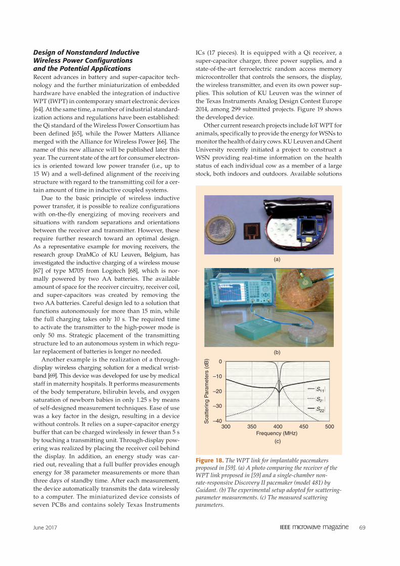
Another example is the realization of a through-
display wireless charging solution for a medical wrist-
band [69]. This device was developed for use by medical
staff in maternity hospitals. It performs measurements
of the body temperature, bilirubin levels, and oxygen
saturation of newborn babies in only 1.25 s by means
of self-designed measurement techniques. Ease of use
was a key factor in the design, resulting in a device
without controls. It relies on a super-capacitor energy
buffer that can be charged wirelessly in fewer than 5 s
by touching a transmitting unit. Through-display pow-
ering was realized by placing the receiver coil behind
the display. In addition, an energy study was car-
ried out, revealing that a full buffer provides enough
energy for 38 parameter measurements or more than
three days of standby time. After each measurement,
the device automatically transmits the data wirelessly
to a computer. The miniaturized device consists of
seven PCBs and contains solely Texas Instruments
ICs (17 pieces). It is equipped with a Qi receiver, a
super-capacitor charger, three power supplies, and a
state-of-the-art ferroelectric random access memory
microcontroller that controls the sensors, the display,
the wireless transmitter, and even its own power sup-
plies. This solution of KU Leuven was the winner of
the Texas Instruments Analog Design Contest Europe
2014, among 299 submitted projects. Figure 19 shows
the developed device.
Other current research projects include IoT WPT for
animals, specifically to provide the energy for WSNs to
monitor the health of dairy cows. KU Leuven and Ghent
University recently initiated a project to construct a
WSN providing real-time information on the health
status of each individual cow as a member of a large
stock, both indoors and outdoors. Available solutions
0
–10
–20
–30
–40Scatteri
ng
Para
mete
rs (
dB
)
300 350 400
Frequency (MHz)
(c)
(b)
(a)
450 500
|S11|
|S21|
|S22|
|S11|
|S21SS |
|S22SS |
Figure 18. The WPT link for implantable pacemakers proposed in [59]. (a) A photo comparing the receiver of the WPT link proposed in [59] and a single-chamber non-rate-responsive Discovery II pacemaker (model 481) by Guidant. (b) The experimental setup adopted for scattering-parameter measurements. (c) The measured scattering parameters.

70 June 2017
for this kind of configuration consists of onboard bat-
tery-powered hardware [70]; regular replacement of
the battery hinders the widespread application of this
wireless solution. The goal of the project is to make
use of specific and regular time slots (e.g., the animal's
drinking) to wirelessly charge a super-capacitor inte-
grated in a small, collar-attached box—thus leading to
a maintenance-free technology. The energy stored on
the super-capacitors can then be used for longer-haul
wireless communications and powering the animal's
wireless body-sensor network. Aspects such as the
distance between the drinking troughs, the time the
animal typically needs to drink, and the energy con-
sumption during autonomous operation determine
the design space for this inductive wireless power
solution. This work is supported by the iMinds-Moni-
Cow project (cofunded by iMinds, a research institute
founded by the Flemish Government in 2004) and the
involved companies and institutions.
Implantable, Inductively Powered UHF RFID TagThis section provides a short overview of the devel-
opment of a system design for a humanbody implant
with a UHF RFID tag powered by IWPT. More details
about the design can be found in [71a].
A classic RFID tag is usually passive, and its opera-
tion is enabled by power received from an RFID reader
during communication [71]. However, in the case of
the implantable tag, the power emitted by the reader
at 866 MHz in the UHF frequency band is dissipated
in the human body tissue. Increasing thickness of
the tissue between the reader and the tag leads to a
decrease in the tag's sensitivity for communication
due to an insufficient level of power for tag operation.
The problem can be overcome with the help of a tag
using a semiactive chip. Powering this kind of chip
can be assured not only by the reader but also by an
additional source. In this case, the additional source
delivering power by IWPT [72] at 6.78 MHz in the
industrial, scientific, and medical (ISM) frequency
band is considered.
Figure 20(a) and (b) shows the mutual arrangement
and scheme of the side of the reader and the side of
the tag, respectively. The elements for RFID commu-
nication and powering through IWPT on the side of
the reader are designed as a center-excised Archime-
des spiral antenna and a circular loop, respectively
[see Figure 21(a)]. These elements on the side of the
tag are represented by a folded dipole antenna and a
rectangular loop [see Figure 21(b)]. Additional circuits
are connected between the powering pins of the tag's
RFID chip and the rectangular loop as well as to the
circular loop to assure efficient powering.
The structure of the reader side is designed to
be placed on the surface of the human body. The
structure of the tag side is compact and suitable for
implantation into the human body. The communica-
tion sensitivity of the tag is increased by 21 dB with
the help of IWPT.
WPT UnderwaterToday, deploying sensors in underwater environments
is standard practice in several fields of activity, such
as environmental monitoring aimed at collecting data
on water or seabed parameters as well as to inspect
permanent subsea infrastructures. These sensors
may be located in fixed or mobile structures. Sensors
deployed on permanent subsea structures or on the
seabed generally lack cabled connections and there-
fore rely on batteries. Approaching these sensors with
Reader-Side Structure
Tag-Side Structure
Human Body Tissue
Human Body Tissue
R RA
RR
LR LT
RT
CT
DT
CDCR
RL TLReader Side Tag Side
VRRCTA
M
(a)
(b)
PS
Figure 20. (a) A cross section of a mutual arrangement of reader-side and tag-side structures. (b) The system scheme. R: reader; RA: reader antenna; TA: tag antenna; RC: RFID chip; VR: voltage regulator; PS: power source; RL: reader loop; TL: tag loop.
(a) (b)
Figure 19. User-friendly, through-display charging of a medical wristband and its autonomous functionality: (a) the charging of the device and (b) the performance of a measurement.

June 2017 71
autonomous underwater vehicles (AUVs) to replen-
ish their batteries and recover measurement data is
very appealing. However, presently the most common
solution involves the operation of remotely operated
vehicles (ROVs), which is very expensive because a
support vessel is required; therefore, this can be con-
sidered only for small-scale operations. On the other
hand, sensors may be carried by mobile underwater
vehicles such as ROVs or AUVs for underwater sensing
in specific missions. In fact, the deployment of AUVs
is an emerging practice, potentially suitable for large-
scale autonomous operation [72], [80]. Figure 22 shows
the MARES AUV, a highly flexible, small-scale AUV,
developed at the Institute for Systems and Computer
Engineering, Technology, and Science (INESC TEC),
that can operate at a maximum depth of 100 m and be
configured to carry specific prototypes and logging
systems for experimental evaluation [73].
The use of AUVs is limited by the duration of their
energy-source charge. Therefore, there is a need for
an energy solution that can support the operation of a
number of AUVs within underwater environments for
long periods of time. Currently available AUV recharg-
ing solutions are very complex, typically requiring
so-called wet-mate connectors [74], which are prone to
failure and require frequent maintenance and/or overly
complex docking mechanisms. As such, these solutions
are not appropriate for scaling up due to the high costs;
therefore, their use has been limited. Research on tech-
niques for underwater WPT has been growing over the
past few years, targeting not only the battery charging
of AUVs but also wireless powering of underwater sensors.
Witricity released a white paper in 2013 [75] demon-
strating the possibility of using resonant magnetic
coupling through salt water. The authors transferred
power across a plastic container filled with water and
used a halogen lamp as a load. They concluded that a
significant power level (up to several kilowatts) may be
transferred across a gap of 15 cm with wireless trans-
fer efficiency in the order of 80%. Inductive coupling is
currently the alternative to wet-mate connectors most
often seen in the literature.
For instance, the authors of [76] describe an under-
water WPT system based on inductive coupling. The
efficiency and power transfer capability reported
are very good, 90% and 400 W, respectively. How-
ever, the operating distance is extremely small,
2 mm. This means that there is no margin for error
in terms of alignment in the AUV charging scenario.
This is also the reason that in these cases some kind
of mechanical stabilization is usually required. For
instance, in [77] the charging station is outfitted with
cones. In [78], an underwater WPT system is reported
with wireless transfer efficiency of 60% across a gap
of 10 cm using an antenna 25 cm × 25 cm in size.
The authors state that the energy flow in seawater
is guided by eddy currents caused by the magnetic
field (although the power level is not mentioned).
A novel WPT technique that considers the coupling
RFID Antenna
RFID Antenna
RFID Chip
Rectifier
SMA
Inputs
CR
LR
LT
CT
DT CD
IWPT Loop
IWPT Loop100
100
VR 25
25
(a) (b)
Figure 21. (a) The reader-side structure and (b) the tag-side structure. Dimensions are in millimeters. Properties of substrate: . , ( ) . , . mm.tan h3 00 0 0014 0 76rf d= = = SMA: subminiature version A.
Figure 22. The MARES AUV developed at INESC TEC.

72 June 2017
through the electric field rather than from the mag-
netic field is resonant electrical coupling (REC),
which was independently proposed by [79] and [80]
in 2014. However, deployment of REC for underwater
WPT has not yet been reported.
The following discusses the results from an under-
water WPT system evaluation using three-dimen-
sional (3-D) electromagnetic simulation. As shown in
Figure 23, we consider two different architectures: a
coil-based and a spiral-based copper inductor setup,
both having a maximum diameter of 16 cm and 3 mm
of copper thickness. In both cases, a parallel capaci-
tor was included to achieve antiresonance at around
100 kHz, where the system operates optimally using
50-Ω impedance at both the transmitter and load sides.
Seawater was considered as the transfer medium
(permittivity of 81 and conductivity of 4 S/m), while
the transmitter and receiver where kept in a box filled
with distilled water to avoid resonance losses. A third
configuration based on parallel plates was evaluated
to assess the viability of the REC principle for under-
water WPT. However, the conductivity of the trans-
fer medium was observed to dramatically reduce the
efficiency of the method, rendering it useless even at
very short ranges.
The simulated efficiency as a function of the sea-
water gap is presented in Figure 24. As can be seen,
the efficiency remains approximately constant in the
overcoupled region, up to 8 cm and 13 cm, for the
coil-based and spiral-based inductors, respectively.
Efficiency falls rapidly after that point, correspond-
ing to the undercoupled region. Depending on the
requirements of the problem at hand, any of the solu-
tions may be attractive. Underwater WPT using mag-
netic resonance appears to be a promising solution to
transfer power to underwater equipment.
REC in WPTThe wireless transfer of power based on electrical res-
onance mentioned in the previous section is based on
the circuit model shown in Figure 25. In this circuit,
power is wirelessly transferred from the source (on
the left) to the load (on the right) through the capaci-
tances C3 and C4. The resonances at the transmitter
and the receiver are defined by L1 and C1 and by L2
and C2, respectively. As shown in [81], a very reason-
able efficiency can be achieved with very low values of
C3 and C4, as long as the losses, represented by R1 and
R2, are kept low. This is similar to resonant magnetic
coupling in the sense that very reasonable efficien-
cies can be achieved with very low magnetic coupling
coefficients if the losses are kept low. Low values of
C3 and C4 and low magnetic coupling coefficients are
extremely important to the increase of spatial freedom.
Spatial freedom is currently one of the most desirable
properties in WPT.
An implementation of the circuit in Figure 25, con-
sisting of two identical devices, is shown in Figure 26.
Each device measures approximately 16 cm × 16 cm ×
3.6 cm and is composed of a coil and two conductive
plates identical in area. The capacitances C1 and C2 are
implemented by the close proximity of the conductive
plates in each device. Figure 27 shows the voltage mea-
sured at the terminals of a 680-Ω load connected to the
output of an RF–dc converter. As shown in Figure 26,
the RF–dc converter is connected to one of the devices,
with the other device connected to a signal generator.
RI RO
VOVI
R1 R2L1 L2I1 I2
I3 I4
C1C2
C3
C4
V1V2+
+
Figure 25. The circuit model considered in studying REC.
(a) (b)
Figure 23. Two underwater WPT simulation models: (a) a coil-based inductor and (b) a spiral-based inductor.
80
70
60
50
Effic
iency (
%)
40
30
20
10
00 5 10 15 20 25 30
Seawater Gap (cm)
Autotuned–Coil
Fixed Frequency–CoilAutotuned–Spiral
Fixed Frequency–Spiral
Figure 24. The efficiency versus seawater gap for both configurations shown in Figure 23.

June 2017 73
At this point, experimental peak efficiencies of 61%
and 38% can be obtained at distances of 12 cm and
30 cm, respectively.
It is also possible to observe a relatively low variation
of peak voltage in the case of a rotational misalignment,
in particular when the receiver is perpendicular to
the transmitter, as shown in Figure 28. However, it is
important to note that this behavior is most likely
caused by the constructive combination of REC and res-
onant magnetic coupling addressed in [82], rather than
REC alone.
WPT Applications
WPT Integration in BuildingsThe physical layer is crucial for the effective integration
of the electronics with any hosting object. Mechanical
flexibility, high shape customization, recyclability, and
low fabrication-process and materials costs are needed
to enable the IoT. For these reasons, particular atten-
tion has to be given by the scientific community to
demonstrating substrate-independent processes that
make possible the application of the devices on many
materials, especially those not normally used in elec-
tronics [85]. Common substrate-independent processes
that fit these requirements include inkjet printing [7],
3-D printing, gravure printing, screen printing, and
metal adhesive laminate [86], [87].
As a case of study, we consider so-called energy
evaporation, a system in which localization capabili-
ties in conjunction with long- and short-range WPT func-
tionalities are combined and embedded into floors [88].
This example is significant because it shows the need
for integration between large-area electronic devices
and the environment.
Figure 29(a) shows the scheme of a distributed
matrix of unit cells composed of a 5.8-GHz patch antenna
surrounded by a high-frequency coil at 13.56 MHz.
The patch is responsible for long-range WPT, while the
coil has the dual role of short-distance WPT source and
localization through connection with near-field com-
munication tags. In Figure 29(b), the performance of
the unit cell fabricated on top of a cork substrate dem-
onstrates the scheme's feasibility, adopting a material
that is unconventional for electronics (but common in
indoor environments). The fabrication was performed
using a metal adhesive method [87].
The importance of the result shown in Figure 29 is
its demonstration that, if properly designed, RFID tags
and RFID sensors could be integrated in tiles and simi-
lar construction materials, thus enabling a variety of
novel energy-autonomous IoT and WPT applications.
Algorithmic WPT Applications in Wireless Ad Hoc NetworksWPT technologies offer new possibilities for manag-
ing the available energy and lead the way toward a
2.5
2
Voltage (
V)
1.5
1
0.5
0
1
2
3
4
5
12 12.5 13 13.5 14 14.5 15
Frequency (MHz)
Figure 27. The measured voltage as a function of frequency for distances equal to 12 cm (curve 1), 16 cm, 20 cm, 24 cm, and 30 cm (curve 5), considering a transmitted power of 16 dBm.
2.5
2
Voltage (
V)
1.5
1
0.5
0
3
4
5
1
2
12 12.5 13 13.5 14 14.5 15
Frequency (MHz)
Figure 28. The measured voltage as a function of frequency for angles equal to −90° (curve 1), −40°, 0° (the same as in Figure 27), 40°, and 90º (curve 5), considering a transmitted power of 16 dBm and a distance of 16 cm.
Figure 26. The prototype used in the experimental validation of REC.

74 June 2017
new paradigm for wireless ad hoc networking [89].
WPT-enabled networks consist of nodes that may be
either stationary or mobile, as well as a few mobile
nodes with high energy supplies [90]. The latter, by
using WPT technologies, are capable of quickly re -
charging the network nodes. In this way, the highly
constrained resource of energy can be managed very
precisely and efficiently. Another important aspect is
that energy management can be performed passively
from the perspective of nodes and without the com-
putational and communication overhead introduced
by complex energy-management algorithms. Finally,
energy management can be studied and designed
independently of the underlying routing mechanism
used for data propagation.
There are considerable challenges in making such
wireless-power-enabled ad hoc networks work. First,
the control of wireless chargers, whether stationary or
mobile, is not trivial. Assuming a finite initial energy,
these devices have a limited lifetime, so their avail-
able energy supplies should be injected into the net-
work wisely. Second, the WPT process is, in itself, a
challenging task. For example, the extent to which a
network node should be charged to prolong the global
network's lifetime is not obvious. Finally, other issues
such as the amount of energy given to the chargers,
the trajectory they should follow inside the network,
and their behavior with respect to the communication
pattern and the energy dissipation inside the network
further complicate the design and implementation of a
wireless ad hoc network of this kind. An example lay-
out of a proof-of-concept setting for WPT in wireless
ad hoc networks is shown in Figure 30.
The charging process's impact on the network's
lifetime is studied in [91] for selected routing proto-
cols. Following a detailed experimental evaluation, a
mobile charging protocol that locally adapts the circu-
lar trajectory of the mobile charger to the energy dis-
sipation rate of each network subregion is proposed
and compared against several other trajectories. The
derived findings demonstrate significant performance
gains in uniform network deployments.
The authors of [92] propose three alternative proto-
cols for efficient recharging, addressing key issues iden-
tified as 1) the extent to which each sensor should
be recharged, 2) the best split of the total energy
between the charger and the sensors, and 3) the
optimal trajectories the mobile charger should fol-
low. One of the protocols performs some limited,
distributed sampling of the network status; another
reactively adapts to energy shortage alerts judiciously
spread across the network. As detailed simulations
demonstrate, both protocols significantly outperform
known state-of-the-art methods and get quite close
to the performance of the global knowledge method,
which is also discussed, especially in heterogeneous
network deployments.
The idea of deploying multiple mobile chargers in a
network is investigated in [93]. Here, four new proto-
cols for efficient recharging are proposed, addressing
optimal coordination procedures and good trajectories
for mobile chargers. Two of the protocols perform lim-
ited, distributed network knowledge coordination and
charging, while two others perform centralized global
network knowledge coordination and charging. As
detailed simulations demonstrate, one of the distrib-
uted protocols outperforms a known state-of-the art-
method [93a], while its performance gets quite close
Short-Range WPT
13.56 MHz
Long-Range WPT
5.8 GHz
(a)
0
–5
–10
–15
–20
–25
5.0 5.5 6.0 6.5
Frequency (GHz)
Tag Detected
ExperimentalSimulated
S11 (
dB
)
(b)
Figure 29. Energy evaporation: (a) an illustration of the concept and (b) the performance of a unit cell fabricated on cork. Based on [86].
Figure 30. The layout of an experimental setting for WPT in wireless ad hoc networks.

June 2017 75
to the performance of the powerful centralized global
knowledge method.
The collaborative charging feature is enhanced in
[94] by forming a hierarchical structure. Two types
of chargers are distinguished: hierarchically lower
mobile chargers, which charge sensor nodes, and
hierarchically higher special chargers, which charge
the mobile chargers. Four new collaborative charging
protocols are designed and implemented to achieve
efficient charging and improve important network
properties. The protocols are either centralized or
distributed and assume different levels of network
knowledge. Extensive simulation findings demon-
strate significant performance gains with respect to
noncollaborative state-of-the-art charging methods.
In particular, the protocols improve several network
properties and metrics, such as network lifetime, rout-
ing robustness, coverage, and connectivity. A useful
feature of these methods is that they can be suitably
added on top of noncollaborative protocols to further
enhance their performance.
In [95], another approach is followed to study the
problem of efficiently charging a set of rechargeable
nodes using a set of wireless energy chargers, impos-
ing safety constraints on the electromagnetic radiation
incurred. A new charging model is defined that dif-
fers greatly from existing models in that it takes into
account real technology restrictions on the chargers
and system nodes, mainly regarding energy limita-
tions. The model also introduces nonlinear constraints
(in the time domain) that radically change the nature
of the computational problems considered. In this
charging model, the low-radiation efficient charging
(LREC) problem is presented and studied; here, the
amount of “useful” energy transferred from chargers
to nodes (under constraints on the maximum level of
imposed radiation) is optimized. Several fundamental
properties of this problem are presented, and indica-
tions of its difficulty are shown. Finally, an iterative
local improvement heuristic for LREC is proposed,
which runs in polynomial time and the performance
of which is evaluated via simulation. The algorithm
decouples the computation of the objective function
from the computation of the maximum radiation and
also does not depend on the exact formula used for the
computation of the electromagnetic radiation in each
point of the network, thus achieving good tradeoffs
between charging efficiency and radiation control. In
addition, the algorithm exhibits good energy balance
properties. Extensive simulation results supporting
the claims and theoretical results are provided [95].
In [96], wireless power transmitters that charge the
battery of the network nodes in mobile ad hoc networks
are employed, and two new alternative protocols that
configure the activity of the chargers are proposed.
One protocol performs wireless charging focused on
charging efficiency, while the other aims at a proper
balance of the transmitter's residual energy. Toward a
more realistic validation, an evaluation is performed
not in a simulation environment but through an ex -
perimental setting of real devices. Figure 30 shows
the layout of the experimental setting in which four
wireless power transmitters and three wireless sensor
motes were used.
Solution of WPT for Spatially Distributed Nodes of WSNsWSNs based on the ZigBee protocol, for example, are
low-power, low-throughput networks commonly used
for distributed low-range sensing and control. In some
cases, spatially distributed ZigBee nodes cannot be
powered up using batteries or cables. In these cases,
an RF-based WPT system can be considered a potential
solution. Because demand on power for each WSN
node can vary over time, the charging system must
constantly monitor the state of each node and send an
adequate amount of energy to allow constant opera-
tion. Examples of other WPT schemes for WSNs can be
found in [96] and [97].
This work presents a concept and physical realiza-
tion of a 2.45-GHz WPT system for charging WSN
nodes that are spatially distributed. The system uti-
lizes a 4 × 1 patch-array transmitter with a switched
radiation beam to ensure large spatial coverage. The
beamswitching is realized using a 4 × 4 Butler matrix,
the inputs of which are connected to an SP4T four-way
high-isolation RF switch. After connecting the switch to
the high-power signal generator (here, a WSN node
generating a single-tone, 2.45-GHz signal along with
a 1-W amplifier for each Butler matrix input to in -
crease the power level), a directional transmitter
was obtained. On the receiving side, the RF power was
collected using a highly directional planar Yagi-Uda
antenna. The antenna was connected to a rectifier includ-
ing a five-stage voltage multiplier and a matching circuit
for a high dc output level. The output of the rectifier
was connected to the 0.47-F super-capacitor gather-
ing energy for powering one WSN node. In total,
four receivers were used in the proposed system, each
placed in the maximum gain direction of each trans-
mitter radiation pattern. The schematic drawing of the
system is shown in Figure 31.
During the operation of a WSN node, measure-
ments of certain physical quantities can be completed
(by a WSN in the receiver site in Figure 31) and sent
to the data sink. Apart from that, each WSN node
can measure and send the voltage level of the super-
capacitor to which it is connected. The voltage levels
can be collected periodically from each WSN node to
the data sink located at the transmitter. Based on WSN
node responses, the transmitter radiation pattern can
be autonomously switched in time to cover current
energy demand of each WSN node and thus allow the
network to remain operational for a long time.

76 June 2017
Using received voltage levels, the transmitter can
switch radiation patterns according to the follow-
ing algorithm:
1) Receive voltage levels from all nodes.
2) Calculate difference and offset from the limit
voltage value for each node.
3) Calculate illumination duration for each node,
i.e., the weighted sum of factors from point 2).
4) Start counter and switch radiation patterns in cal-
culated moments.
5) Go to point 1).
Figure 32 shows a WPT system for automated charg-
ing of WSN nodes. To verify performance of the WPT
system, a charging experiment was performed. In
the experiment, all WSN nodes both measured and
sent data to the sink while being charged accord-
ing to the algorithm. Voltage levels measured by all
WSN nodes versus time are presented in Figure 33.
As can be seen, the node with the lowest voltage
level obtains the highest amount of energy from the
transmitter. Other nodes discharge slowly, but in case
of high energy loss (the sudden voltage drop shown in
Figure 33), the system would direct the energy flow to
the nodes most in need of energy.
The presented 2.45-GHz WPT system allows wire-
less charging of multiple WPT nodes by switching
the transmitter’s radiation pattern. The implemented
algorithm allows full automation of the charging
process and also equalization of voltage levels for all
WSN nodes, independent of the node’s measurement
frequency and initial voltage level.
Exploitation of 3-D Textile Materials for Wireless Feeding of In-Car Sensor NetworksThe 3-D textile material shown in Figure 34 consists
of two firm layers at a constant distance. The distance
between the layers is kept constant by fine fibers per-
pendicular to the firm layers. Hence, the 3-D fabric
can be understood as a dielectric waveguide. This
3-D fabric can be used as upholstery in cars, buses, or
airplanes, and such upholstery can play the role of a
feeder or a communication channel.
The idea of exploiting a 3-D textile material for
a WPT was tested in a car with a metallic roof (Fig-
ure 35). The transmit antenna and receive antenna
were attached to a 3-D textile upholstery. Using this
technique, the electromagnetic energy was efficiently
guided by the textile material along the car roof.
Receivers
WSNNode
WSNNode
WSNNode
WSNNode
Rectenna
Rectenna
Rectenna
Rectenna
Transmitter
4 × 4
Butler
Matrix
Amplifier
Amplifier
Amplifier
Amplifier
SP4T
2.45 GHz
Figure 31. The schematic of the proposed WPT system.
Transmitter and Receivers
Receiver Antennas
Transmitter Antenna
Butler Matrix
Generator + Switch
+ Amplifiers
Figure 32. An autonomous WPT system realized for supplying power to WSN nodes distributed in space.
3.3
3.23.1
32.9
2.8
Super-
Capacitor
Voltage (
V)
2.7
2.62.5
2.40 20 40 60 80 100 120 140 160
Time (min)
N1N2N3N4
Fully Automated Charging
Sudden Voltage Drop
Figure 33. The results of the charging experiment for the example system shown in Figure 32.

June 2017 77
The idea was verified by measurements in a real
car. In Figure 36, the transmission between antennas
in free space (black) is compared with the transmis-
sion between antennas placed on the roof upholstery
of an empty car (blue) and a fully occupied car (red).
The efficiency of the described WPT is demonstrated
in Figure 37, which compares transmission between
the transmit antenna and the receive antenna placed
in free space (black), on conventional upholstery
(blue), on 3-D textile (green), and in 3-D textile (red).
To minimize attenuation of the channel, the trans-
mitted electromagnetic wave must be polarized perpen-
dicularly to the metallic surface of the roof. Therefore,
an open-ended rectangular waveguide and a planar
horn antenna integrated to the substrate were used in
the experiments (Figure 38).
For experiments in a car, the planar horn antenna inte-
grated to the substrate showed better behavior, thanks to
its narrower radiation pattern (Figure 39). For measure-
ments in the laboratory, the open-ended rectangular
waveguide was exploited due to a simpler calibration.
Harmonic TagsIn the field of passive UHF RFID, the nonlinear behav-
ior of the harvesting section of the RFID chip can be
exploited to develop augmented tags. Three categories
of applications can be envisaged by exploiting 1) the
impedance power dependency [101], [102], 2) har-
monic generation [103]–[105], and 3) efficient waveform
design [106]–[108].
To enable such applications, the nonlinear
characteristics of the RFID chip must be determined.
Figure 40 shows the normalized power spectral density of
Rx Tx
Figure 35. An experimental radio link that runs along the roof of a vehicle using a 3-D textile upholstery. Rx: receive; Tx: transmit.
–46
–48
–50
Tra
nsm
issio
n C
oeffic
ient (d
B)
→
–52
–54
–56
–58
–6057.5 58 58.5 59 59.5 60 60.5
Frequency (GHz) →
61 61.5 62 62.5
Empty Car Occupied Car Free Space
Figure 36. The transmission between SIW horn antennas fixed on 3-D textile upholstery on the roof of a car.
–20
–25
–30
–35
–40
Tra
nsm
issio
n C
oeffic
ient (d
B)
→
–4557.5 58 58.5 59 59.5 60 60.5
Frequency (GHz) →
61 61.5 62 62.5
Free Space On Upholstery
On 3-D Textile Into 3-D Textile
Figure 37. The transmission between antennas over a distance of 180 mm in free space (black), on conventional upholstery (blue), on 3-D textile (green) and in 3-D textile (red).
(b)(a)
Figure 38. (a) The planar horn antenna integrated to a substrate and (b) the open-ended rectangular waveguide.
Figure 34. The 3-D textile material.
20
10
0
–10
–20Gain
(dB
i) →
–300 20 40 60 80 100 120 140 160 180
θ, φ (°) →
H
E
Figure 39. The directivity patterns of the planar horn antenna integrated to substrate in the E plane (red) and H plane (blue).

78 June 2017
a passive RFID chip response measured using a similar
method to the one reported in [104]. The setup considers
the chip activation threshold power, the reader harmon-
ics suppression, and the chip impedance matching at the
fundamental frequency as in common tags. The har-
monic frequency level (i.e., at 1.736 GHz and, notably, at
2.604 GHz) at the chip activation threshold is signifi-
cant compared to the fundamental frequency level. The
energy contained in the third harmonic generated by
the RFID chip can be exploited to set a second RF tag-to-
reader link at that harmonic frequency.
Harmonic Tag DesignA proper design of the tag antenna enables the trans-
mission of the modulated third harmonic signal from
tag to reader [102]. The obtained channel diversity can
be exploited as a redundant communication channel,
e.g., to increase the robustness of the RF uplink. Addi-
tionally, the pattern direction of the antenna can be
designed to be different than the one for the fundamen-
tal signal, e.g., to develop an application for localization.
It can also be used to enable some specific applications
by receiving the signal at the third harmonic.
MeasurementFigure 41 shows an example of a harmonic tag using a
dual-band, low-frequency inverted antenna. Figure 42
shows the third order harmonic response levels of two
prototypes based on the harmonic tag with a differ-
ent chip in each one (chip 1 [108] and chip 2 [109]) and
one commercial tag. The results of an experimental
parametric analysis are summarized in Table 2.
10 15 20 25 30 35–115
–110
–105
–100
–95
–90
–85
–80
–75
EIRP Transmitted Power (dBm)
Isotr
opic
Receiv
ed
Pow
er
(dB
m)
Harmonic Tag–Chip 2
Harmonic Tag–Chip 1
Commercial Tag
Figure 42. The isotropic received power of the harmonic tag response at the third harmonic in function of the EIRP transmitted by the reader. The measured power considers an isotropic antenna at reception in a bistatic configuration with 1-m distance between the reader and tag.
0
–15
–30
–45
Norm
aliz
ed
Pow
er
(dB
)
–60
–75
0.8 1.0 1.2 1.4 1.6 1.8 2.0 2.2 2.4 2.6
Frequency (GHz)
SecondHarmonic
Third Harmonicto Be Exploited
RFID Signal forCommunication
at 868 MHz
Figure 40. An example of the normalized power spectral density of a tag response measured at the activation threshold of the chip under test.
x
y
RFID Chip
62 mm
60 m
m
Figure 41. An example of a harmonic tag. It communicates at the fundamental frequency and third harmonic. The RFID chip is connected to the dual band antenna with appropriate matching sections.
TABLE 2. Parametric analysis results.
Frequency
Power
of the
Response
at 3f
Read
Range at
the Third
Harmonic*
Fabrication
sensitivity
12-MHz
detuning
−82 dBm High
dependency
Kind of chip Greater
bandwidth
with chip 1
Quasi-similar
for both chips
3.5 m for
chip 2
3.0 m for
chip 1
Commercial
tag
Slightly wider
bandwidth for
commercial tag
−90 dBm Lower than
1.5 m
* The read range at 3f0 considers −90 dBm of reader sensitivity.

June 2017 79
As can be seen in Table 1, the read range at the third
harmonic is a few meters, which is comparable to that
at fundamental frequency in this design. However, the
design of the antenna at the third harmonic could be
quite different to enable new applications. Localiza-
tion, energy harvesting, sensing, and authentication
are among the possible options.
UHF RFID Library Management SystemA passive UHF RFID library management system (LMS)
was designed and built to serve the purpose of a univer-
sity library [112]. The prototype was actually built and
tested in a laboratory setting with very good evaluation
results. The main objectives of the project were to 1) pro-
vide stock management, including inventory monitor-
ing, identification of missing or lost library items, and
locating books on shelves; 2) implement item security
measures against possible thefts often incurred in librar-
ies; and 3) eliminate time-consuming processes when
checking items out of the library or returning items to
the library.
A block diagram of the RFID-enabled LMS is shown
in Figure 43. It consists of several subsystems includ-
ing smart shelves, a user self-service desk, a database
server, a portal security system, and a mobile cart unit.
The database server is the backbone for the entire sys-
tem. It is the place where all the relevant information
such as book titles, user accounts, checked-out books,
and stock-taking reports are kept.
Using the self-service desk [see Figure 44(b)-(c)],
which consists of a PC, an RFID reader, and a near-field
antenna, library users can perform all functions that
Smart Shelves
Multiplexer
Administrator’s Desk User Self-Service Desk
Database Server Mobile Cart Unit Portal Security System
LAN/Wireless LAN Network Internet
Wi-FiFirewall
Figure 43. A block diagram of the RFID-enabled LMS. LAN: local-area network.
(a) (b) (c)
Figure 44. (a) The mobile cart unit equipped with an RFID reader, antenna, and autonomous power supply; (b) and (c) the self check-out/in counter for library users.

80 June 2017
typically take place in a library environment: search
for a book by title, author, publisher, or ISBN number. In
addition, they are allowed to review their own activity
record, self-checkout books, and return to the library pre-
viously checked-out books. A user-friendly graphical
interface was developed to provide users with enhanced
functionality and transparency. Through this interface,
the librarian has additional privileges compared to the
average user, including the ability to modify system set-
tings, edit user accounts and book entries (e.g., add new
books), take stock, and monitor the RFID entrance secu-
rity system (shown in Figure 43).
The smart shelves of the LMS, depicted in Fig-
ure 45, are especially designed to serve the tasks
of the university library. Each cabinet is equipped
with an RFID reader with multiple ports connected
through cables to each of its shelves. Although these
shelves look like common shelves, they are, in fact,
especially designed RFID antennas, such as the one
illustrated in Figure 46, through which the reader can
receive the unique identification numbers (electronic
product code) of the books that are placed on top of
them. This enables automatic stock-taking with the
push of a button, as well as locating and identify-
ing missing and misplaced books on library shelves
in record time. RF multiplexers (as shown in Fig-
ure 47) are also used at intermediate points between
the reader and the shelf antennas to reduce the total
number of readers required to cover the overall needs
of the library. The multiplexers are software-controlled
(using Arduinos), and they are already implemented
in the in-house developed software application.
Each RFID reader can be connected and service up to
32 antennas.
A security portal at the entrance of the library, as
shown in Figure 43, consists of a stationary RFID reader
and a high-gain antenna or array of antennas. This sys-
tem is connected to the network to provide access to the
software application developed for this purpose. Alert
information is passed to a dedicated software applica-
tion that runs on the circulation desktop, which is
controlled by the library administrator. The system is
programmed to activate an alarm every time a nonau-
thorized attempt is made to remove library items (e.g.,
books and magazines) from the library entrance.
A mobile cart unit, shown in Figure 44(a), enables
book identification and localization on the library
shelves. The mobile cart system is equipped with an
RFID reader, an antenna, a laptop/tablet with touch
screen, and a UPS that provides power to the reader
and laptop. The system uses the Wi-Fi connection to
access the database server and provide valuable infor-
mation to the user. The mobile cart can be pushed
around the library while scanning the books on indi-
vidual shelves.
The ability of the system to effectively read and
correctly identify the books residing on top of the
shelf antenna depends on the electromagnetic cover-
age, the uniformity and strength of the field in the
volume of the shelf, and the interference to nearby
shelves. It was identified experimentally that tag re -
adability requires a minimum field level of approxi-
mately 20 dBV/m [113]. The wooden cabinet that was
built and tested in the laboratory was also modeled
on SEMCAD-X using a FDTD algorithm [114]. Our
goal was to identify problematic regions either due to
reduced electromagnetic coverage or strong interfer-
ence in neighboring shelves.
In Figure 48, the areas where the electric field val-
ues are above 20 dBV/m are shown in yellow for two
antenna designs: a straight line and a meander line.
Figure 48(a) and (b) represents the field magnitude for
the straight line; Figure 48(c) and (d) represents the
corresponding field for the meander line. The straight
line was excited with a power source set to 20 dBm,
whereas the meander line was excited with a power
source at 15 dBm. It is clear that both antennas result Figure 46. The shelf antenna with an N-type connector on the side.
RFID ReaderRFID Reader
Figure 45. The prototype library cabinet with four shelves. The shelf antennas are fed on the side with coaxial cables running from the reader’s ports or the multiplexer. Books (equipped with RFID tags) reside on top of the shelf antennas.
June 2017 81
in reduced electromagnetic interference for nearby
shelves. However, the meander line with a lower input
power level seems to provide a better electromagnetic
coverage and even lower electromagnetic interference.
In addition to electromagnetic coverage and inter-
ference at nearby shelves, the distribution of the peak
spatial specific absorption rate (SAR), averaged over
10 g of tissue mass (psSAR10g), was assessed for a hu -
man model (phantom) [115] in close proximity to shelf
antennas with and without the presence of books
on the shelf. The dielectric properties of the human
tissues were calculated according to the parametric
model proposed by Gabriel et al. [114]. In the worst-
case scenario, all shelf antennas in the cabinet were
active. All values were normalized to 1 W of power
radiated by each antenna.
In the case of the wooden cabinet and straight-line
antennas, higher psSAR10g values were calculated when
the model was placed at the shortest distance to the
shelf but in the absence of books. SAR values were
in all cases reduced by a factor of ten as compared to
those obtained for a metallic cabinet. Specifically, at
5-mm distance, the maximum SAR values are 0.076 W/kg
for Thelonious (see Figure 49), 0.059 W/kg for Ella, and
0.041 W/kg for Duke (all these are all human models)
[114]. When the human models were placed 10 cm away
from the cabinet, the corresponding SAR values were
reduced to 0.022 W/kg, 0.015 W/kg, and 0.012 W/kg, for
Thelonious, Ella, and Duke, respectively.
WPT for Batteryless Biomedical and Implantable MicrosystemsWPT is desperately needed in wearable biomedical sen-
sors [116], implants [117], individually addressable
neurostimulators [118], retinal and other prostheses
[119], and biomedical applications such as interven-
tional magnetic resonance imaging (MRI) [120]. In each
of these critical applications, there is an important size
constraint on a system that makes the use of batteries
impractical because this limits overall size and shortens
lifetime. Certain applications such as MRI have high-
power internal electromagnetic fields that prohibit the
use of long metallic wires due to induced heating. There-
fore, power and data transmission must be done wire-
lessly to the systems in these applications, and they must
be miniaturized.
Antenna 1 Antenna 1
Reading Range
Antenna 2
Reading Range
Antenna 2
Antenna 3
Antenna 4
To MultiplexerTo MultiplexerFeeding Path
Figure 47. The proposed library cabinet composed of four shelves. Each of the four shelf antennas is connected to an RF multiplexer output.
(a) (b) (c) (d)
Figure 48. Electromagnetic coverage and interference for nearby shelves. The yellow color corresponds to the magnitude of the electric field above 20 dBV/m. (a)–(b) The shelf antenna is a straight microstrip line at the bottom of the shelf; (c)–(d) the shelf antenna is a meander line at the bottom of the shelf.
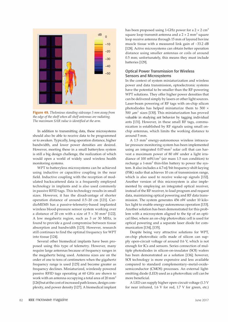
82 June 2017
In addition to transmitting data, these microsystems
should also be able to receive data to be programmed
or to awaken. Typically, long operation distance, higher
bandwidth, and lower power densities are desired.
However, meeting these in a small batteryless system
is still a big design challenge, the realization of which
would open a world of widely used wireless health
monitoring systems.
WPT to batteryless microsystems can be achieved
using inductive or capacitive coupling in the near
field. Inductive coupling with the reception of mod-
ulated backscattered data is a frequently employed
technology in implants and is also used commonly
in passive RFID tags. This technology results in small
sizes. However, it has the disadvantage of shorter
operation distance of around 0.5–20 cm [121]. Car-
dioMEMS has a passive-telemetry-based implanted
wireless blood-pressure sensor system working over
a distance of 20 cm with a size of 5 × 30 mm2 [122].
A low megahertz region, such as 3 or 30 MHz, is
found to provide a good compromise between tissue
absorption and bandwidth [123]. However, research
still continues to find the optimal frequency for WPT
into tissue [124].
Several other biomedical implants have been pro-
posed using this type of telemetry. However, many
require large antennas because of frequency ranges in
the megahertz being used. Antenna sizes are on the
order of one to tens of centimeters when the gigahertz
frequency range is used [125] and become greater as
frequency declines. Miniaturized, wirelessly powered
passive RFID tags operating at 60 GHz are shown to
work with an antenna occupying a total area of 20 mm2
[126] but at the cost of increased path losses, design com-
plexity, and power density [127]. A biomedical implant
has been proposed using 1-GHz power for a 2 × 2 cm2
square loop transmit antenna and a 2 × 2 mm2 square
loop receive antenna through 15 mm of layered bovine
muscle tissue with a measured link gain of −33.2 dB
[128]. Active microsystems can obtain better operation
distance using smaller antennas or coils of around
0.5 mm; unfortunately, this means they must include
batteries [129].
Optical Power Transmission for Wireless Sensors and MicrosystemsIn the context of system miniaturization and wireless
power and data transmission, optoelectronic systems
have the potential to be smaller than the RF-powering
WPT solutions. They offer higher power densities that
can be delivered simply by lasers or other light sources.
Laser-beam powering of RF tags with on-chip silicon
photodiodes has helped miniaturize them to 500 ×
500 m2n sizes [130]. This miniaturization has proved
valuable in studying ant behavior by tagging individual
ants [131]. However, in these small RF tags, commu-
nication is established by RF signals using small on-
chip antennas, which limits the working distance to
around 5 mm.
A 1.5 mm3 energy-autonomous wireless intraocu-
lar pressure monitoring system has been implemented
using an integrated 0.07-mm2 solar cell that can har-
vest a maximum power of 80 nW under a light irra-
diance of 100 mW/cm2 (air mass 1.5 sun condition) to
recharge a 1-mm2 thin-film battery to power the sys-
tem. It also includes a 4.7-nJ/bit frequency-shift keying
(FSK) radio that achieves 10 cm of transmission range,
which is also used to receive wake-up signals [132].
Another version of this microsystem is also imple-
mented by employing an integrated optical receiver,
instead of the RF receiver, to load program and request
data, maintaining optical powering and RF data trans-
mission. The system generates 456 nW under 10 kilo-
lux light to enable energy-autonomous operation [133].
Another solution has been demonstrated for this prob-
lem with a microsystem aligned to the tip of an opti-
cal fiber, where an on-chip photovoltaic cell is used for
optical powering and a separate laser diode for com-
munication [134], [135].
Despite being very attractive solutions for WPT,
on-chip photovoltaic cells made of silicon can sup-
ply open-circuit voltage of around 0.6 V, which is not
enough for ICs and sensors. Series connection of mul-
tiple photodiodes in silicon-on-insulator (SOI) wafers
has been demonstrated as a solution [136]; however,
SOI technology is more expensive and less available
compared to standard complementary–metal-oxide-
semiconductor (CMOS) processes. An external light-
emitting diode (LED) used as a photovoltaic cell can be
more beneficial.
A LED can supply higher open-circuit voltage (1.3 V
for near infrared, 1.6 V for red, 1.7 V for green, etc.)
dB0
–10
–20
–30
–40
–50
Figure 49. Thelonious standing sideways 5 mm away from the edge of the shelf when all shelf antennas are radiating. The maximum SAR value is identified at the arm.

June 2017 83
than silicon photodiodes. Circuitry can be run directly
from this higher voltage without the need for voltage
elevation, which consumes valuable power. Because
the microsystem needs an external optoelectronic
element to transmit data optically (silicon, being an
indirect semiconductor, cannot generate photons of
any sufficient quantity), the LED can also work as a
data transceiver. Placing the photodiode outside the IC
die saves expensive on-chip area. With the photovol-
taic cell placed out of the die, the die can be covered in
optically opaque material because the powering light
can induce latch-up and noise and increase leakage
currents. Photon absorption is more efficient in direct
bandgap materials of LEDs [e.g., aluminium gallium
arsenide (AlGaAs)] in contrast to indirect bandgap
materials (e.g., silicon) [137]. Record-level efficiency
improvements in GaAs solar cells have been achieved
in this way, stressing commonalities between efficient
photovoltaic cell and LED designs [138]. An LED is also
an efficient photovoltaic cell for a limited range of its
wavelengths, which are about 20–30-nm shorter than
the peak emission wavelength.
With the added benefits of LEDs, an improvement
in a wireless and batteryless optoelectronic microsys-
tem has been made by using it for both wireless pow-
ering and data transmission, as depicted in Figure 50.
The use of a single LED having a die size of 350 ×
350 m2n with the help of an IC (230 × 210 m
2n ) and
a storage capacitor (0.5 × 1 mm2) resulted in a 1-mm3
wireless and batteryless microsystem [139].
For transcutaneous implants, optical powering
can be accomplished using light with wavelengths
between 600 and 900 nm (called the near-infrared win-
dow), where hemoglobin absorbs weakly and penetra-
tion of light can reach a maximum depth of around
5 cm [140]. Experimental results show that the laser
power level of 1 W/cm2 drops to 1 mW/cm2 (30-dB
power loss) through 3.4-cm-thick bovine tissue when
a 808-nm wavelength is used [141].
Design of Batteryless CMOS Sensors for RF-Powered WSNsThe WSN is a group of spatially dispersed sensors
(nodes) to collect physical or environmental infor-
mation and cooperatively pass that information
through the network to a central location. A WSN has
several applications, e.g., building monitoring and
automation, health-care monitoring, air pollution
monitoring, forest-fire detection, and water-quality
monitoring. Normally, each network node comprises
a radio transceiver, a microcontroller, sensors, and
an energy source, usually a battery. The lifetime of
most sensors is mainly limited by the autonomy of
their batteries. There are several solutions for extend-
ing the life of batteries, among which we can include
the harvesting of electromagnetic energy available
in the environment. As semiconductor technologies
evolve over time, not only the size of MOS transistors
decreases toward nanometric scales; the circuits'
power consumption is also considerably reduced. This
trend favors the integration of several complex func-
tions in a system-on-chip. It is thus possible to inte-
grate complete ultralow-power autonomous sensors
for RF-powered WSNs.
UMONS Microelectronics Laboratory is engaged in
designing a wireless RF-powered temperature sensor.
The architecture of the temperature sensor is depicted
in Figure 51. RF energy is harvested with an receive
antenna that is adapted to a rectifier/multiplier through
an inductor/capacitor (LC) matching network to maxi-
mize energy transfer. The rectifier output charges an
external capacitor that supplies the rest of the circuits
on the chip. A power-management unit checks and
regulates the minimum voltage level required across
the external capacitor. It also controls the sensor work-
ing cycle by properly enabling/disabling each block in
view of minimal power consumption. The temperature
Electromagnetic
Energy Harvesting in
ISM Band (2.4 GHz)External
CapacitorFour-FSK
867 MHz
LCMatchingNetwork
Rectifier PowerManager
T°
Sensor
100-kHz
Clock VCO
DAC28
Modulator
Turn On/Off CommandClock
Data Path
Figure 51. A wireless and batteryless temperature sensor architecture.
Optically
DeliveredPower
Optical Data
Transmission
Integrated Circuit Die
AIGaAs LED Die
External Storage
Capacitor
Figure 50. A conceptual representation of an optically powered and optically transmitting microsystem using a single LED.

84 June 2017
is measured with an ultralow-power temperature sen-
sor that delivers a digital word to a modulator, which
yields the transmission frame. The modulator output
controls a voltage-controlled oscillator (VCO) through
a digital-to-analog converter (DAC) to generate the
four-FSK signal, which is transmitted by a transmit
antenna. A 100-kHz master-clock generator provides
the time reference for all digital circuits of the sensor.
For a 15.6-ms long transmission frame at 50 kb/s, the
bit error rate results in 10−4. The system can operate
at 0.5 V, while consuming 84 µW in on mode and
28.6 nW in idle mode. The achieved input sensitivity
is −26 dBm.
The use of low-threshold voltage transistors avail-
able in the 65-nm CMOS technology allows a system
capable of operating at ultralow voltage. This fact,
together with the adopted design methodology [142],
permitted significant reduction in power consumption
and increase in rectifier sensitivity compared to prior
works [143].
AcknowledgmentsThe work presented in this paper was accomplished
within the European Union COST Action IC1301.
The work of J. Kracek, M. Svanda, M. Mazanek,
and J. Machac was supported by the Czech Ministry
of Education, Youth and Sports within the framework
of the project LD14122 Electromagnetic Structures and
Circuits for Wireless Power Transmission.
References[1] M. Pinuela, D. C. Yates, S. Lucyszyn, and P. D. Mitcheson, “Maxi-
mizing DC-to-load efficiency for inductive power transfer,” IEEE
Trans. Power Electron., vol. 28, no. 5, pp. 2437–2447, May 2013.
[2] M. S. Trotter, J. D. Griffin, and G. D. Durgin, “Power-optimized
waveforms for improving the range and reliability of RFID sys-
tems,” in Proc IEEE Int. Conf. RFID, 27–28 Apr. 2009, pp. 80–87.
[3] A. S. Boaventura and N. B. Carvalho, “Maximizing dc power in en-
ergy harvesting circuits using multisine excitation,” in Proc. IEEE
MTT-S Int. Microwave Symp. Digest, Jun. 5–10, 2011.
[4] A. Collado and A. Georgiadis, “Improving wireless power trans-
mission efficiency using chaotic waveforms,” in Proc. IEEE MTT-S
Int. Microwave Symp. Digest, Montreal, 17–22 June 2012.
[5] A. Collado and A. Georgiadis, “Optimal waveforms for efficient
wireless power transmission,” IEEE Microwave Wireless Compon
Lett., vol. 24, no. 5, pp. 354–356, May 2014.
[6] A. Georgiadis, A. Collado, and K. Niotaki, “Rectenna design and
signal optimization for electromagnetic energy harvesting and
wireless power transfer,”’ IEICE Trans. Electron., vol. E98-C, no. 07,
pp. 608–612, July 2015.
[7] H. Sakaki, S. Yoshida, K. Nishikawa, and S. Kawasaki, “Analysis of
rectifier operation with FSK modulated input signal,” in Proc. IEEE
Wireless Power Transfer Conf., May 2013, pp. 187–190.
[8] G. Fukuda, S. Yoshida, Y. Kai, N. Hasegawa, and S. Kawasaki,
“Evaluation on use of modulated signal for microwave power
transmission,” in Proc. 44th European Microwave Conf., Oct. 2014,
pp. 425–428.
[9] J. Blanco, F. Bolos, A. Collado, and A. Georgiadis, “RF-energy
harvesting and wireless power transfer efficiency from digitally
modulated signals,” in Proc. IEEE 15th Mediterranean Microwave
Symp., Lecce, Italy, 2015.
[10] A. Boaventura, D. Belo, R. Fernandes, A. Collado, A. Georgiadis,
and N. B. Carvalho, “Boosting the efficiency: Unconventional
waveform design for efficient wireless power transfer,” IEEE
Microwave Mag., vol. 16, no. 3, pp. 87–96, Apr. 2015.
[11] C. H. P. Lorenz, S. Hemour, W. Liu, A. Badel, F. Formosa, and K.
Wu, “Hybrid power harvesting for increased power conversion
efficiency,” IEEE Microwave Wireless Compon. Lett., vol. 25, no. 10,
pp. 687–689, Oct. 2015.
[12] M. Virili, A. Georgiadis, A. Collado, K. Niotaki, P. Mezzanotte,
L. Roselli, F. Alimenti, and N. B. Carvalho, “Performance improve-
ment of rectifiers for WPT exploiting thermal energy harvesting,”
Wireless Power Transfer, vol. 2, no. 1, pp. 22–31, Mar. 2015.
[13] D. Belo and N. Borges Carvalho, “Harmonic spaced multisines
for efficient wireless power transmission,” in Proc. IEEE Wireless
Power Transfer Conf., Boulder, May 2015
[14] D. Belo, J.-M. Munoz-Ferreras, R. Gomez-Garcia, and N. Borges Car-
valho, “Exploiting radar waveforms for wireless power transmis-
sion,” in Proc. IEEE Wireles Power Transfer Conf., Boulder, May 2015.
[15] A. Boaventura, N. B. Carvalho, and A. Georgiadis, “The impact
of multisine tone separation on RF-DC efficiency,” in Proc. Asia-
Pacific Microwave Conf., 4–7 Nov. 2014, pp. 606–609.
[16] N. Pan, A. Boaventura, M. Rajabi, D. Schreurs, N. B. Carvalho, and
S. Pollin, “Amplitude and frequency analysis of multisine wireless
power transfer,” in Proc. Int. Workshop Integrated Nonlinear Micro-
wave and Millimetere-wave Circuits Conf., Oct. 2015.
[17] Federal Communications Commission. “Revision of part 15 of
the Commission’s Rules Regarding Ultra-Wideband Transmission
Systems, First Rep. Order (ET Docket 98-153),” Adopted Feb. 14,
2002. Released Apr. 22, 2002.
[18] Electronic Communications Committee (ECC). “Specific UWB
Applications in the bands 3.4-4.8 GHz and 6.8-8.5 GHz Location
Tracking Applications for Emergency Services (LAES), Location
Tracking Applications Type 2 (LT2) and Location Tracking and
Sensor Applications for Automotive and Transportation Environ-
ments (LTA), Oct. 2011.
[19] S. Lemey and H. Rogier, “SIW textile antennas as a novel technol-
ogy for UWB RFID tags,” in Proc. IEEE RFID Technology and Ap-
plications Conf., Sept. 2014, pp. 256–260.
[20] O. Caytan, S. Lemey, S. Agneessens, D. Vande Ginste, P. De-
meester, C. Loss, R. Salvado, and H. Rogier, “Half-mode sub-
strate-integrated-waveguide cavity-backed slot antenna on cork
substrate,” IEEE Antenn. Wireless Propagat. Lett., 2015. doi: 10.1109/
LAWP.2015.2435891.
[21] R. Moro, S. Agneessens, H. Rogier, A. Dierck, and M. Bozzi, “Tex-
tile microwave components in substrate integrated waveguide
technology,” IEEE Trans. Microwave Theory Tech., vol. 63, no. 2,
pp. 422–432, Feb. 2015.
[22] S. Lemey, F. Declercq, and H. Rogier, “Textile antennas as hy-
brid energy harvesting platforms,” Proc. IEEE, vol. 102, no. 11,
pp. 1833–1857, Nov. 2014.
[23] T. Cuyckens and H. Rogier, “Framework for the simulation of
wireless power transmission over ultra wide band links in mul-
tipath propagation environments in the vicinity of the human
body,” Int. J. Numer. Model. Electron. Netw. Devices Field, vol. 28,
Mar. 2015. doi: 10.1002/jnm.2070.
[24] G. Stockman, H. Rogier, and D. Vande Ginste, “Dedicated model
for the efficient assessment of wireless power transfer in the radia-
tive near-field,” Int. J. Numer. Model. Electron. Netw. Devices Field,
vol. 28, Apr. 2015. doi: 10.1002/jnm.2075.
[25] [Online] Available: www.ti.com/lit/ds/symlink/bq25570.pdf
[26] H.J. Visser and S. Keyrouz, “Radiative RF Power Transfer Solu-
tions for Wireless Sensors,” in Proc. IEEE Int. Symp. Antennas and
Propagation, Memphis, TN, 2014, pp. 1401–1402.
[27] [Online] Available: http://arduino.cc/en/main/arduinoboard-
mega2560
[28] H. J. Visser, H. W. Pflug, and S. Keyrouz, “Rectenna demonstra-
tors at Holst Centre/imec and Eindhoven University of Technology,”

June 2017 85
in Proc. European Conf. Antennas and Propagation, Lisbon, Portugal,
2015, pp. 44.
[29] M. Stoopman, S. Keyrouz, H.J. Visser, K. Philips and W.A. Serdijn,
“A self-calibrating RF energy harvester generating 1V at –26.3-
DBm,” in Proc. Symp. VLSI Circuits, 2013, pp. C226–C227.
[30] A. Takacs, H. Aubert, S. Fredon, L. Despoisse, and H. Blondeaux,
“Microwave power harvesting for satellite health monitoring,” IEEE
Trans. Microwave Theory Tech., vol. 62, no. 4, pp. 1090–1098, Apr. 2014.
[31] [Online] Available: www.laas.fr
[32] Z. Popovic, E. A. Falkenstein, D. Costinett, and R. Zane, “Low-
power far-field wireless powering for wireless sensors,” in Proc.
IEEE, vol. 101, no. 6, pp. 1397–1407, June 2013.
[33] A. Takacs, H. Aubert, and S. Charlot, “Ultra-compact Ku band
rectenna,” in Proc. IEEE MTT-S Int. Microwave Symp., Phoenix,
June, 2015, pp. 17–22.
[34] A. Massa, G. Oliveri, F. Viani, and P. Rocca, “Array designs for
long-distance wireless power transmission—State-of-the-art and
innovative solutions,” IEEE Proc., vol. 101, no. 6, pp. 1464–1481, June
2013.
[34a] P. Rocca, G. Oliveri, R. J. Mailloux, and A. Massa, “Unconven-
tional phased array architectures and design methodologies: A
review,” in Proc. IEEE, vol. 104, no. 3, pp. 544–560, Mar. 2016.
[35] P. E. Glaser, “The potential of satellite solar power,” in Proc. IEEE,
vol. 65, no. 8, pp. 1162–1176, Aug. 1977.
[36] G. Oliveri, L. Poli, and A. Massa, “Maximum efficiency beam
synthesis of radiating planar arrays for wireless power transmis-
sion,” IEEE Trans. Antenn. Propagat., vol. 61, no. 5, pp. 2490–2499,
May 2013.
[37] G. Franceschetti, P. Rocca, F. Robol, and A. Massa, “Innovative
rectenna design for space solar power systems,” in Proc. IEEE
MTT-S Int. Microwave Workshop Series on “Innovative Wireless Power
Transmission: Technologies, Systems, and Applications,” Kyoto, Japan,
May 2012, pp. 151–153.
[38] P. Rocca, G. Oliveri, and A. Massa, “Array synthesis for opti-
mal wireless power systems,” in Proc. IEEE AP-S Int. Symp. and
USNC-URSI Radio Science Meeting, Memphis, Tennessee, July 2014,
pp. 1407–1408 (Invited paper).
[39] L. Manica, P. Rocca, and A. Massa, “Design of subarrayed linear
and planar array antennas with SLL control based on an excitation
matching approach,” IEEE Trans. Antenn. Propagat., vol. 57, no. 6,
pp. 1684–1691, Jun. 2009.
[40] F. Viani, G. Oliveri, and A. Massa, “Compressive sensing pattern
matching techniques for synthesizing planar sparse arrays,” IEEE
Trans. Antennas Propagat., vol. 61, no. 9, pp. 4577–4587, Sept. 2013.
[41] A. G. Dimitriou, A. Bletsas, and J. N. Sahalos, “Room coverage im-
provements of UHF RFID with commodity hardware,” IEEE Trans.
Antennas Propagat., vol. 53, no. 1, pp. 175–194, Feb. 2011.
[42] A. G. Dimitriou, A. Bletsas, A. Polycarpou, and J. N. Sahalos,
“Theoretical findings and measurements on planning a UHF
RFID system inside a room,” Radioeng. J., vol. 20, no. 2, pp. 387–397,
June 2011.
[43] I. T. Markakis, T. Samaras, A. C. Polycarpou, and J. N. Sahalos,
“An RFID-enabled Library Management System using Low-SAR
Smart Bookshelves,” in Proc. Int. Conf. Electromagnetics Advanced
Applications, Torino, Italy, Sept. 2013, pp. 227–230.
[44] A. G. Dimitriou, S. Siachalou, A. Bletsas, and J. N. Sahalos, “A
site-specific stochastic propagation model for passive UHF RFID,”
IEEE Antenn. Wireless Propagat. Lett., vol. 13, pp. 623–626, Mar. 2014.
[45] A. G. Dimitriou, S. Siachalou, A. Bletsas, and J. N. Sahalos,
“Site-specific stochastic propagation model for automated RFID
network planning,” in Proc. Int. Conf. Electromagnetics Advanced
Applications, Torino, Italy, Sept. 2013, pp. 603–606.
[46] A. G. Dimitriou, A. Boursianis, I. Markakis, S. Siachalou, T. Sama-
ras, and J. N. Sahalos, “Comparison of a fast probabilistic propa-
gation model against an analytical computational-EM model and
measurements for the evaluation of passive RFID systems,” in
Proc. 9th European Conf. Antennas and Propagation, Lisbon, Portugal,
Apr. 2015.
[47] A. G. Dimitriou, S. Siachalou, A. Bletsas, and J. N. Sahalos, “Auto-
mated RFID network planning with site-specific stochastic model-
ing and particle swarm optimization,” in Proc. IEEE RFID Technol-
ogy and Applications Conf., Tampere, Finland, Sept. 2014, pp. 44–49.
[48] M. Dionigi and M. Mongiardo, “Numerical electromagnetic mod-
elling of a wireless power transfer system,” in Proc. IEEE Int. Conf.
Numerical Electromagnetic Modeling and Optimization for RF, Micro-
wave, and Terahertz Applications, May 2014, pp. 1–8.
[49] M. Dionigi, M. Mongiardo, and R. Perfetti, “Rigorous network
and fullwave electromagnetic modeling of wireless power transfer
links,” IEEE Trans. Microwave Theory Tech., vol. 63, no. 1, pp. 65–75,
Jan. 2015.
[50] A. Kurs, A. Karalis, R. Moffatt, J. D. Joannopoulos, P. Fisher, and
M. Soljacic, “Wireless power transfer via strongly coupled mag-
netic resonances,” Science, vol. 317, no. 5834, pp. 83–86, 2007.
[51] A. Costanzo, M. Dionigi, M. Masotti, M. Mongiardo, G. Monti,
L. Tarricone, and R. Sorrentino, “Electromagnetic energy harvest-
ing and wireless power transmission: A unified approach,” in
Proc. IEEE, vol. 102, no. 11, pp. 1692–1711, Nov. 2014.
[52] A. Costanzo, M. Dionigi, F. Mastri, M. Mongiardo, J. A. Russer,
and P. Russer, “Rigorous design of magnetic-resonant wireless
power transfer links realized with two coils, in Proc. European
Microwave Conf., Rome, Italy, 2014, pp. 414–417.
[53] A. Costanzo, M. Dionigi, F. Mastri, M. Mongiardo, J. A. Russer,
and P. Russer, “Rigorous network modeling of magnetic-resonant
wireless power transfer,” Wireless Power Transfer, vol. 1, no. 1,
pp. 27–34, 2014.
[54] J. Russer and P. Russer, “Design considerations for a moving field
inductive power transfer system,” in Proc. IEEE Wireless Power
Transfer, May 2013, pp. 147–150.
[55] J. A. Russer, M. Dionigi, M. Mongiardo, and P. Russer, “A moving
field inductive power transfer system for electric vehicles,” in Proc.
IEEE European Microwave Conf., Nuremberg, Germany, Oct. 2013,
pp. 519–522.
[56] J. A. Russer, M. Dionigi, M. Mongiardo, and P. Russer, “A bidi-
rectional moving field inductive power transfer system for electric
vehicles,” in Proc. 11th IEEE Int. Conf. Telecommunication in Modern
Satellite, Cable and Broadcasting Services, Oct. 2013, vol. 1, pp. 17–20.
[57] J.A. Russer M. Dionigi, M. Mongiardo, F. Mastri, A. Costanzo,
and P. Russer, “A system for dynamic inductive power supply of
electric vehicles on the road,” in Proc. IEEE Wireless Power Transfer
Conf., Aveiro, 2016.
[58] G. Monti, L. Tarricone, and C. Trane, “Experimental characteriza-
tion of a 434 mhz wireless energy link for medical applications,”
Prog. Electromagnet. Res. C, vol. 30, pp. 53–64, May 2012.
[59] G. Monti, P. Arcuti, and L. Tarricone, “Resonant inductive link
for remote powering of pacemakers,” IEEE Trans. Microwave Theory
Tech., vol. 63, no. 11, pp. 3814–3822.
[60] G. Monti, M. D. Paolis, and L. Tarricone, “Wireless energy link for
deep brain stimulation,” in Proc. European Microwave Conf., Paris,
France, Sept. 2015, pp. 1–4.
[61] G. Monti, M. D. Paolis, and L. Tarricone, “Wireless power transfer
link for rechargeable deep brain stimulators,” in Proc. Mediterra-
nean Microwave Symp., Lecce, Italy, 2015, pp. 1–4.
[62] F. Mastri, A. Costanzo, M. Dionigi, and M. Mongiardo, “Harmon-
ic balance design of wireless resonant-type power transfer links,”
in Proc. IEEE MTT-S Int. Microwave Workshop Series on Innovative
Wireless Power Transmission: Technologies, Systems, and Applications,
2012, pp. 245–248.
[63] A. Costanzo, M. Dionigi, F. Mastri, and M. Mongiardo, “Rigorous
modeling of mid-range wireless power transfer systems based on
Royer oscillators,” in Proc. IEEE Wireless Power Transfer, pp. 69–72, 2013.
[64] [Online] Available: http://www.qinside.biz/en/support/qi-enabled-
phones-2015

86 June 2017
[65] [Online] Available: http://www.wirelesspowerconsortium.com
[66] [Online] Available: http://a4wppmamerge.com/Release.pdf
[67] B. Thoen and N. Stevens, “Development of a communication scheme
for wireless power applications with moving receivers,” IEEE Trans.
Microwave Theory Tech., vol. 63, no. 3, pp. 857–863, Mar. 2015.
[68] [Online] Technical specifications. Available: http://www.logitech
.com/en-us/product/marathon-mouse-m705
[69] S. Wielandt, B. Thoen, J. Goemaere, D. Strycker, and N. Stevens,
“Inductive charging of an EDLC powered wristband device for
medical measurements,” in Proc. 22nd IEEE European Conf. Circuit
Theory and Design, Trondheim, Norway, Aug. 2015.
[70] [Online] Available: http://www.bellaag.com
[71] K. Finkenzeller, RFID Handbook: Fundamentals and Applications in
Contactless Smart Cards and Identification, 2nd ed. New York: Wiley,
2005.
[71a] J. Kracek, M. Svanda, M. Mazanek, and J. Machac, “Implantable
semi-active UHF RFID tag with inductive wireless power transfer,”
IEEE Antenn. Wireless Propagat. Lett., vol. 15, pp. 1657–1660, 2016.
[72] J. Kracek and M. Mazanek, “Wireless power transmission
for power supply: State of art,” Radioengineering, vol. 20, no. 2,
pp. 457–463, 2011.
[73] R. B. Wynn, et al. “Autonomous Underwater Vehicles (AUVs):
Their past, present and future contributions to the advancement of
marine geoscience,” Mar. Geol., vol. 352, pp. 451–468, 2014.
[74] N. A. Cruz and A. C. Matos, “The MARES AUV, a modular au-
tonomous robot for environment sampling,” in Proc. IEEE Oceanic
Engineering Society, Sept. 2008, pp. 1–6.
[75] T. Kojiya, F. Sato, H. Matsuki, et al. “Automatic power supply sys-
tem to underwater vehicles utilizing non- contacting technology,”
in Proc. IEEE Oceanic Engineering Society, 2004, pp. 2341–2345.
[76] M. Kesler and C. McCarthy, “Highly resonant wireless power
transfer in subsea applications,” Witricity white paper, 2013.
[77] Z.-S. Li, D.-J. Li, L. Lin, and Y. Chen, “Design considerations for
electromagnetic couplers in contactless power transmission sys-
tems for deep-sea applications,” J. Zhejiang Univ. Sci. C, vol. 11,
no. 10, pp. 824–834, 2010.
[78] J.-G. Shi, D.-J. Li, and C.-J. Yang, “Design and analysis of an un-
derwater inductive coupling power transfer system for autono-
mous underwater vehicle docking applications,” J. Zhejiang Univ.
Sci. C, vol. 15, no. 1, pp. 51–62, 2014.
[79] K. Shizuno, S. Yoshida, M. Tanomura, and Y. Hama, “Long dis-
tance high efficient underwater wireless charging system using
dielectric-assist antenna,” in Proc. IEEE Oceanic Engineering Soci-
ety, 2014, pp. 1–3.
[80] R. D. Fernandes, J. N. Matos, and N. B. Carvalho, “Behavior of
resonant electrical coupling in terms of range and relative orienta-
tion,” in Proc. IEEE Wireless Power Transfer Conf., 2014, pp. 118–121.
[81] R. D. Fernandes, J. N. Matos, and N. B. Carvalho, “Resonant elec-
trical coupling: circuit model and first experimental results,” IEEE
Trans. Microwave Theory Tech., vol. 63, no. 9, pp. 2983–2990, Sept. 2015.
[82] R. D. Fernandes, J. N. Matos, and N. B. Carvalho, “Constructive
combination of resonant magnetic coupling and resonant electri-
cal coupling,” in Proc. IEEE Wireless Power Transfer Conf., Boulder,
CO, May, 2015.
[83] C. Yang and K. Tsunekawa, “Analysis and performance improve-
ment of independent electric coupled resonance WPT system with
impedance transformer,” in Proc. IEEE Wireless Power Transfer
Conf., 2014, pp. 239–242.
[84] R. B. Wynn, et al. “Autonomous underwater vehicles (AUVs):
Their past, present and future contributions to the advancement of
marine geoscience,” Mar. Geol., vol. 352, pp. 451–468, 2014.
[85] L. Roselli, N. Borges Carvalho, F. Alimenti, P. Mezzanotte,
G. Orecchini, M. Virili, C. Mariotti, R. Goncalves, and P. Pinho,
“Smart surfaces: Large area electronics systems for internet of
things enabled by energy harvesting,” in Proc. IEEE, vol. 102,
no. 11, pp. 1723–1746, Nov. 2014.
[86] B. Cook, C. Mariotti, J. Cooper, D. Revier, B. Tehrani, L. Aluigi,
L. Roselli, and M. Tentzeris, “Inkjet-printed, vertically-integrated,
high performance inductors and transformers on flexible LCP sub-
strate,” in Proc. IEEE MTT-S Int. Microwave Symp., 2014.
[87] F. Alimenti, P. Mezzanotte, M. Dionigi, M. Virili, and L. Roselli,
“Microwave circuits in paper substrates exploiting conductive ad-
hesive tapes,” IEEE Microwave Wireless Compon. Lett., vol. 22, no. 12,
pp. 660–662, Dec. 2012.
[88] C. Mariotti, R. Gonalves, L. Roselli, N. Carvalho, and P. Pinho,
“Energy evaporation”: The new concept of indoor systems for
wpt and eh embedded into the floor,” in Proc. IEEE Int. Microwave
Symp., 2015.
[89] S. Nikoletseas and T. P. Raptis, “Efficient protocols for wireless
power transfers in ad hoc networks,” in Cyber-Physical Systems.
Boca Raton, FL: CRC, 2015, pp. 527–558.
[90] S. Nikoletseas and T. P. Raptis, “Efficient algorithms for charac-
teristic wireless power transfer problems in sensor networks,” in
Lecture Notes of the Institute for Computer Sciences, Social Informat-
ics and Telecommunications Engineering. New York: Springer-Verlag,
2014, vol. 140, pp. 204–215.
[91] C. M. Angelopoulos, S. Nikoletseas, T. P. Raptis, C. Raptopoulos,
and F. Vasilakis. “Efficient energy management in wireless re-
chargeable sensor networks,” in Proc. 15th ACM Int. Conf. Model-
ing, Analysis and Simulation of Wireless and Mobile Systems, 2012. pp.
309–316.
[92] C. M. Angelopoulos, S. Nikoletseas, and T. P. Raptis, “Wireless
energy transfer in sensor networks with adaptive, limited knowl-
edge protocols,” Comput. Netw., vol. 70, pp. 113–141, Sept.2014.
[93] A. Madhja, S. Nikoletseas, and T. P. Raptis, “Distributed wireless
power transfer in sensor networks with multiple mobile chargers,”
Comput. Netw., vol. 80, pp. 89–108, Apr. 2015.
[93a] C. Wang, J. Li, F. Ye, and Y. Yang, “Multi-vehicle coordination for
wireless energy replenishment in sensor networks,” in Proc. 27th
IEEE Int. Parallel & Distributed Processing Symp., 2013, pp. 1101–1111.
[94] A. Madhja, S. Nikoletseas, and T. P. Raptis, “Hierarchical, collab-
orative wireless energy transfer in sensor networks with multiple
mobile chargers,” Comput. Netw., vol. 97, pp. 98–112, Mar. 2016.
[95] S. Nikoletseas, T. P. Raptis, and C. Raptopoulos, “Low radiation
efficient wireless energy transfer in wireless distributed systems,”
in Proc. 34th IEEE Int. Conf. Distributed Computing Syst., 2015, pp.
196–204.
[96] S. Nikoletseas, T. P. Raptis, A. Souroulagkas, and D. Tsolovos,
“An experimental evaluation of wireless power transfer protocols
in mobile ad hoc networks,” in Proc. IEEE Wireless Power Transfer
Conf., 2015, pp. 1–3.
[97] S. Riviere, “An integrated model of a wireless power transporta-
tion for RFID and WSN applications,” in Proc. 16th IEEE Int. Conf.
Electronics, Circuits, and Systems, Dec. 2009, pp. 235–238.
[98] S. Riviere, “Study of complete WPT system for WSN applications
at low power level,” Electron. Lett., vol. 46, no. 8, pp. 597–598, 2010.
[99] M. Roberg, T. Reveyrand, I. Ramos, E. Falkenstein, and Z. Popo-
vic, “High-efficiency harmonically terminated diode and transis-
tor rectifiers,” IEEE Trans. Microwave Theory Tech., vol. 60, no. 12,
pp. 4043–4052, 2012.
[100] R. Scheeler, S. Korhummel, and Z. Popovic, “A dual-frequency
ultralow-power efficient 0.5-g rectenna,” IEEE Microwave Mag.,
vol. 15, no. 1, pp. 109–114, Jan. 2014.
[101] A. Georgiadis, G. Andia, and A. Collado, “Rectenna design and
optimization using reciprocity theory and harmonic balance anal-
ysis for electromagnetic (EM) energy harvesting,” IEEE Antenn.
Wireless Propagat. Lett., vol. 9, pp. 444–446, 2010.
[102] G. Andia Vera, Y. Duroc, and S. Tedjini, “Analysis of harmonics
in UHF RFID signals,” IEEE Trans. Microwave Theory Tech., vol. 61,
no. 6, pp. 2481–2490, 2013.
[103] S. Ladan and K. Wu, “35 GHz harmonic harvesting rectifer for
wireless power transmission,” in Proc. IEEE MTT-S Int. Microwave
Symp. Digest, June 2014, pp. 1–3.

June 2017 87
[104] G. Andia Vera, Y. Duroc, and S. Tedjini, “RFID test platform:
nonlinear characterization,” IEEE Trans. Instrum. Measure., vol. 63,
no. 9, pp. 2299–2305, Sept. 2014.
[105] A. Boaventura and N. Carvalho, “Maximizing dc power in en-
ergy harvesting circuits using multisine excitation,” in Proc. IEEE
MTT-S Int. Microwave Symp. Digest, June 2011, pp. 1–4.
[106] M. Trotter, J. Griffin, and G. Durgin, “Power-optimized wave-
forms for improving the range and reliability of rfid systems,” in
Proc. IEEE Int. Conf. RFID, Apr. 2009, pp. 80–87.
[107] A. Collado and A. Georgiadis, “Optimal waveforms for efficient
wireless power transmission,” IEEE Microwave Wireless Compon.
Lett., vol. 24, no. 5, pp. 354–356, May 2014.
[108] NXP. Ucode g2xm and g2xl product data sheet company public.
[Online]. Available: http://www.nxp.com/documents/data sheet/
SL3ICS1002 1202.pdf
[109] Impinj Monza 5. Impinj uhf rfid product downloads – monza tag
chips. [Online]. Available: http://www.impinj.com
[110] G. Andia-Vera, A. Georgiadis, Y. Duroc and S. Tedjini, “Coop-
erative integration of harvesting sections for passive RFID com-
munication,” in Proc IEEE MTT-S Int. Microwave Symp., Phoenix,
AZ, May 2015.
[111] A. C. Polycarpou, T. Samaras, and J. N. Sahalos, “An RFID-
based library management system using smart cabinets: A pilot
project,” in Proc. 8th European Conf. Antennas & Propagation, 2014,
pp. 2954–2955.
[112] A. C. R. Medeiros, J. R. Costa, and C. A. Fernandes, “RFID reader
antennas for tag detection in self-confined volumes at UHF,” IEEE
Antenn. Propagat. Mag., vol. 53, no. 2, pp. 39–50, Apr. 2011.
[113] A. Christ, W. Kainz, E. G. Hahn, K. Honegger, M. Zefferer, E.
Neufeld, W. Rascher, R. Janka, W. Bautz, J. Chen, B. Kiefer, P. Schmitt,
H. P. Hollenbach, J. Shen, M. Oberle, D. Szczerba, A. Kam, J. W. Guag,
and N. Kuster, “The virtual family—Development of surface-based
anatomical models of two adults and two children for dosimetric
simulations,” Phys. Med. Biol., vol. 55, no. 2, pp. 23–38, 2010.
[114] S. Gabriel, R. W. Lau, and C. Gabriel, “The dielectric properties of
biological tissues: III. Parametric models for the dielectric spectrum
of tissues,” Phys. Med. Biol., vol. 41, no. 11, pp. 2271–2293, Nov. 1996.
[115] SEMCAD, Schmid & Partner Engineering AG (SPEAG) [Online].
Available: http://www.semcad.com
[116] A. Pantelopoulos and N. G. Bourbakis, “A survey on wearable
sensor-based systems for health monitoring and prognosis,” IEEE
Trans. Syst. Man. Cybern. Syst. Rev., vol. 40, no. 1, pp. 1–12, 2010.
[117] J. Walk, J. Weber, C. Soell, R. Weigel, G. Fischer, and T. Ussm-
ueller, “Remote powered medical implants for telemonitoring,” in
Proc. IEEE, vol. 102, no. 11, pp. 1811–1832, 2014.
[118] K. D. Wise, D. J. Anderson, J. F. Hetke, D. R. Kipke, and K. Najafi,
“Wireless implantable microsystems: high-density electronic inter-
faces to the nervous system.,” in Proc. IEEE, vol. 92, no. 1, pp. 76–97, 2004.
[119] T. Schanze, L. Hesse, C. Lau, N. Greve, W. Haberer, S. Kammer, T.
Doerge, A. Rentzos, and T. Stieglitz, “An optically powered single
channel stimulation implant as test system for chronic biocompat-
ibility and biostability of miniaturized retinal vision prostheses,”
IEEE Trans. Biomed. Eng., vol. 54, no. 6, pp. 983–992, June 2007.
[120] S. Fandrey, S. Weiss, and J. Muller, “Development of an active in-
travascular MR device with an optical transmission system,” IEEE
Trans. Med. Image, vol. 27, no. 12, pp. 1723–1727, Dec. 2008.
[121] J. A. Potkay, “Long term, implantable blood pressure monitor-
ing systems,” Biomed. Microdevices, vol. 10, no. 3, pp. 379–392, 2008.
[122] M. Allen, M. Fonseca, J. White, J. Kroh, and D. Stern, “Implant-
able wireless sensor for blood pressure measurement with an ar-
tery 2005,” CardioMEMS, Inc.
[123] A. D. DeHennis and K. D. Wise, “A wireless microsystem for the
remote sensing of pressure, temperature, and relative humidity,”
J. Microelectromech. Syst., vol. 14, no. 1, pp. 12–22, 2005.
[124] A. S. Y. Poon, O’Driscoll. Stephen, and T. H. Meng, “Optimal
frequency for wireless power transmission into dispersive tissue,”
IEEE Trans. Antenn. Propagat., vol. 58, no. 5, pp. 1739–1750, 2010.
[125] K. V. S. Rao, P. V. Nikitin, and S. F. Lam, “Antenna design for
UHF RFID tags: A review and a practical application,” IEEE Trans.
Antenn. Propagat., vol. 53, no. 12, pp. 3870–3876, Dec. 2005.
[126] P. Pursula, T. Vaha-Heikkila, A. Muller, D. Neculoiu, G. Konstan-
tinidis, A. Oja, and J. Tuovinen, “Millimeter-wave identification—
A new short-range radio system for low-power high data-rate
applications,” IEEE Trans. Microwave Theory Tech., vol. 56, no. 10,
pp. 2221–2228, Oct. 2008.
[127] B. W. Cook, S. Lanzisera, and K. S. J. Pister, “SoC issues for RF
smart dust,” in Proc. IEEE, vol. 94, no. 6, pp. 1177–1196, June 2006.
[128] S. O’Driscoll, P. Ada, and T. H. Meng, “A mm-sized implantable
power receiver with adaptive link compensation,” in Proc. IEEE
Int. Solid-State Circuits Conf. Digest Technical Papers, 2009.
[129] I. Lee, Y. Kim, S. Bang, G. Kim, H. Ha, Y.-P. Chen, D. Jeon, et al.
“Circuit techniques for miniaturized biomedical sensors,” in Proc.
IEEE Custom Integrated Circuits Conf., 2014, pp. 1–7.
[130] K. E. Laflin, C. J. Morris, N. Bassik, M. Jamal, and D. H. Gracias,
“Tetherless microgrippers with transponder tags,” J. Microelectro-
mech. Syst., vol. 20, no. 2, pp. 505–511, Apr. 2011.
[131] E. J. Robinson, F. D. Smith, K. M. Sullivan, and N. R. Franks, “Do
ants make direct comparisons?,” in Proc. Biol. Sci., vol. 276, no. 1667,
pp. 2635–2641, July 2009.
[132] M. H. Ghaed, G. Chen, R-U. Haque, M. Wieckowski, Y. Kim, G.
Kim, Y. Lee, et al. “Circuits for a cubic-millimeter energy-autono-
mous wireless intraocular pressure monitor,” IEEE Trans. Circuits
Syst. I, Reg. Papers. , vol. 60, no. 12, pp. 3152–3162, 2013.
[133] G. Kim, L. Yoonmyung, F. Zhiyoong, P. Pat, K. Ye-Sheng, K. Ben,
G. Mohammad Hassan, et al. “A millimeter-scale wireless imag-
ing system with continuous motion detection and energy harvest-
ing,” in Proc. Symp. VLSI Circuits Digest of Technical Papers, 2014,
pp. 1–2.
[134] O. Aktan, B. Sarioglu, U. Cindemir, S. Onur Unlu, G. Dundar,
S. Mutlu, and A. D. Yalcinkaya, “Optoelectronic CMOS power
supply unit for electrically isolated microscale applications,”
IEEE J. Sel. Top. Quantum Electron., vol. 17, no. 3, pp. 747–756,
May/June 2011.
[135] B. Sarioglu, O. Aktan, A. Oncu, S. Mutlu, G. Dundar, and A. D.
Yalcinkaya, “An optically powered CMOS receiver system for in-
travascular magnetic resonance applications,” IEEE Trans. Emerg.
Sel. Topics Circuits Syst., vol. 2, no. 4, pp. 683–691, 2012.
[136] B. A. Warneke, M. D. Scott, B. S. Leibowitz, L. Zhou, C. L. Bellew,
J. A. Chediak, J. M. Kahn, B. E. Boser, and K. S. J. Pister, “An autono-
mous 16 mm3 solar-powered node for distributed wireless sensor
networks,” in Proc. IEEE Sens. vol. 2, pp. 1510–1515, 2002.
[137] P. Bhattacharya, Semiconductor Optoelectronic Devices. New
Jersey: Prentice Hall, 1994.
[138] O. D. Miller, E. Yablonovitch, and S. R. Kurtz, “Strong internal
and external luminescence as solar cells approach the Shock-
ley–Queisser limit,” IEEE J. Photovolt., vol. 2, no. 3, pp. 303–311,
July 2012.
[139] I. Haydaroglu and S. Mutlu, “Optical power delivery and data
transmission in a wireless and batteryless microsystem using a
single light emitting diode,” J. Microelectromech. Syst., vol. 24, no. 1,
pp. 155–165, 2015.
[140] T. Vo-Dinh, Ed. Biomedical Photonics Handbook: Biomedical
Diagnostics, vol. 2. Boca Raton, FL: CRC, 2014.
[141] D. E. Hudson, et al. “Penetration of laser light at 808 and 980
nm in bovine tissue samples,” Photomed. Laser Surg., vol. 31, no. 4,
pp. 163–168, 2013.
[142] R. Fiorelli, “An all-inversion-region gm/ID based design meth-
odology for radio frequency blocks in CMOS nanometer technolo-
gies,” PhD dissertation, CNM Sevilla, Spain, Oct. 2011.
[143] G. Papotto, et al. “A 90-nm CMOS 5-Mbps crystal-less RF-pow-
ered transceiver for wireless sensor network nodes,” J. Solid-State
Circuits, vol. 49, no. 2, pp. 335–346, Feb. 2014.