AC SERVO DRIVES SERIES Series.pdf · AC SERVO DRIVES SERIES JQA-0422 JQA-EM0202 ... high-resolution...
103
AC SERVO DRIVES SERIES JQA-EM0202 JQA-0422 Certified for ISO9001 and ISO14001 Direct Drive Servomotors
Transcript of AC SERVO DRIVES SERIES Series.pdf · AC SERVO DRIVES SERIES JQA-0422 JQA-EM0202 ... high-resolution...
AC SERVO DRIVESSERIES
JQA-EM0202JQA-0422
Certi�ed forISO9001 andISO14001
Direct Drive Servomotors
1
CONTENTS
Direct Drive Servomotors
SGM7D (With Core, Outer Rotor) 118
SGM7E (Coreless, Inner Rotor) 144
SGM7F (With Core, Inner Rotor) 160
SGMCV (Small Capacity, with Core, Inner Rotor) 182
SGMCS (Small Capacity, Coreless, Inner Rotor or Medium Capacity, with Core, Inner Rotor) 196
EichenbergerE
Rechteck
EichenbergerE
Rechteck
EichenbergerE
Rechteck
EichenbergerE
Rechteck
EichenbergerE
Rechteck
EichenbergerE
Rechteck
EichenbergerE
Rechteck
EichenbergerE
Rechteck
EichenbergerE
Rechteck
SGM7D
SGM7E
SGM7F
SGMCV
SGMCS
Direct Drive Servomotors
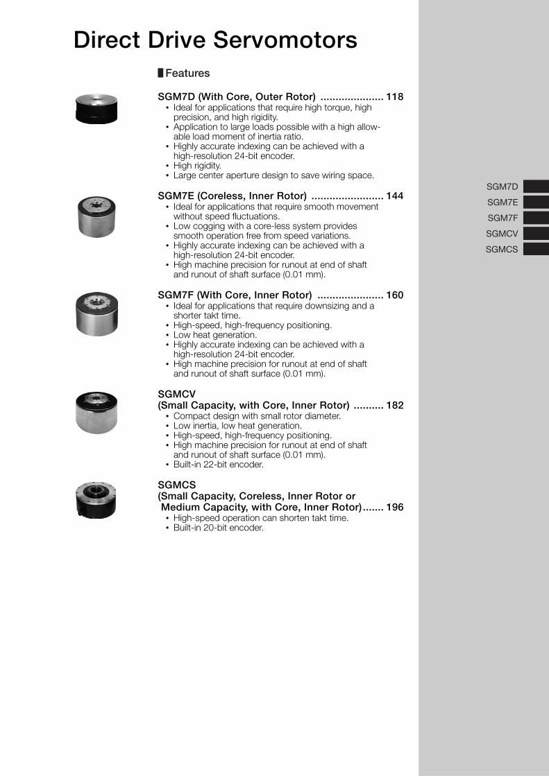
SGM7D (With Core, Outer Rotor) ..................... 118• Ideal for applications that require high torque, high
precision, and high rigidity.• Application to large loads possible with a high allow-
able load moment of inertia ratio.• Highly accurate indexing can be achieved with a
high-resolution 24-bit encoder.• High rigidity.• Large center aperture design to save wiring space.
SGM7E (Coreless, Inner Rotor) ........................ 144• Ideal for applications that require smooth movement
without speed fluctuations.• Low cogging with a core-less system provides
smooth operation free from speed variations.• Highly accurate indexing can be achieved with a
high-resolution 24-bit encoder.• High machine precision for runout at end of shaft
and runout of shaft surface (0.01 mm).
SGM7F (With Core, Inner Rotor) ...................... 160• Ideal for applications that require downsizing and a
shorter takt time.• High-speed, high-frequency positioning.• Low heat generation.• Highly accurate indexing can be achieved with a
high-resolution 24-bit encoder.• High machine precision for runout at end of shaft
and runout of shaft surface (0.01 mm).
SGMCV (Small Capacity, with Core, Inner Rotor) .......... 182
• Compact design with small rotor diameter.• Low inertia, low heat generation.• High-speed, high-frequency positioning.• High machine precision for runout at end of shaft
and runout of shaft surface (0.01 mm).• Built-in 22-bit encoder.
SGMCS(Small Capacity, Coreless, Inner Rotor or Medium Capacity, with Core, Inner Rotor) ....... 196
• High-speed operation can shorten takt time.• Built-in 20-bit encoder.
Features
Direct Drive Servomotors
118
SGM7D (With Core, Outer Rotor)
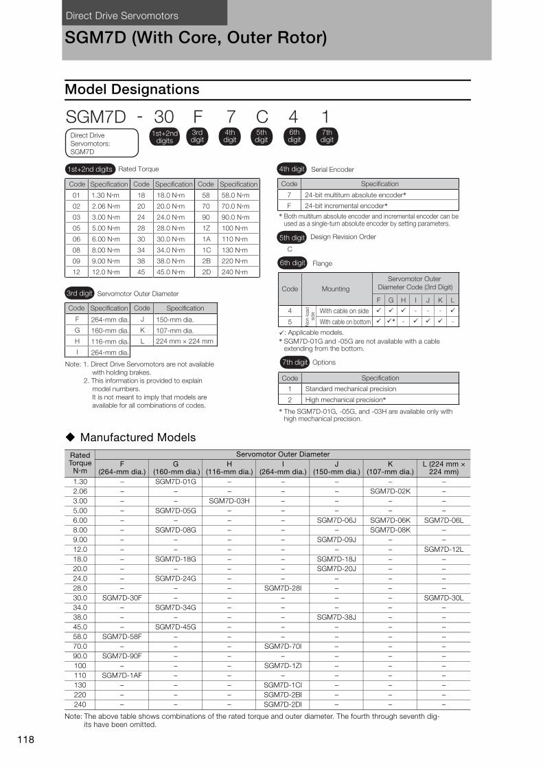
Model Designations
Manufactured Models
Note: The above table shows combinations of the rated torque and outer diameter. The fourth through seventh dig-its have been omitted.
Rated Torque
Nm
Servomotor Outer DiameterF
(264-mm dia.)G
(160-mm dia.)H
(116-mm dia.)I
(264-mm dia.)J
(150-mm dia.)K
(107-mm dia.)L (224 mm ×
224 mm)1.30 – SGM7D-01G – – – – –2.06 – – – – – SGM7D-02K –3.00 – – SGM7D-03H – – – –5.00 – SGM7D-05G – – – – –6.00 – – – – SGM7D-06J SGM7D-06K SGM7D-06L8.00 – SGM7D-08G – – – SGM7D-08K –9.00 – – – – SGM7D-09J – –12.0 – – – – – – SGM7D-12L18.0 – SGM7D-18G – – SGM7D-18J – –20.0 – – – – SGM7D-20J – –24.0 – SGM7D-24G – – – – –28.0 – – – SGM7D-28I – – –30.0 SGM7D-30F – – – – – SGM7D-30L34.0 – SGM7D-34G – – – – –38.0 – – – – SGM7D-38J – –45.0 – SGM7D-45G – – – – –58.0 SGM7D-58F – – – – – –70.0 – – – SGM7D-70I – – –90.0 SGM7D-90F – – – – – –100 – – – SGM7D-1ZI – – –110 SGM7D-1AF – – – – – –130 – – – SGM7D-1CI – – –220 – – – SGM7D-2BI – – –240 – – – SGM7D-2DI – – –
C
Code Specification
7 24-bit multiturn absolute encoder*24-bit incremental encoder*F
SGM7D - 30 F 7 C 4 1
Code MountingServomotor Outer
Diameter Code (3rd Digit)
F
�
�
G
�
�*
H
�
-
I
-
�
J
-
�
K
-
�
4
5
With cable on side
With cable on bottom
1 Standard mechanical precision
�: Applicable models.
Specification
2 High mechanical precision*
L
�
-Non
-load
si
de
Direct Drive Servomotors: SGM7D
4th digit
6th digit
3rd digit
7th digit Options
5th digit Design Revision Order
Servomotor Outer Diameter
Serial Encoder
Flange
1st+2nd digits
1st+2nd digits Rated Torque
3rd digit
4th digit
5th digit
6th digit
7th digit
Code
* SGM7D-01G and -05G are not available with a cable extending from the bottom.
* The SGM7D-01G, -05G, and -03H are available only with high mechanical precision.
* Both multiturn absolute encoder and incremental encoder can be used as a single-turn absolute encoder by setting parameters.
Note: 1. Direct Drive Servomotors are not available with holding brakes.
2. This information is provided to explain model numbers. It is not meant to imply that models are available for all combinations of codes.
F
G
H
I
Code
264-mm dia.
264-mm dia.
116-mm dia.
160-mm dia.
J
L 224 mm × 224 mm
K 107-mm dia.
150-mm dia.
Specification
Code Specification Code Specification
Code Specification Code Specification
01 1.30 N�m
02 2.06 N�m
03 3.00 N�m
05 5.00 N�m
06 6.00 N�m
08 8.00 N�m
09 9.00 N�m
12 12.0 N�m
18 18.0 N�m
20 20.0 N�m
24 24.0 N�m
28 28.0 N�m
30 30.0 N�m
34 34.0 N�m
38 38.0 N�m
45 45.0 N�m
1Z 100 N�m
1A 110 N�m
1C 130 N�m
2B 220 N�m
2D 240 N�m
58 58.0 N�m
70 70.0 N�m
90 90.0 N�m
Direct Drive Servomotors SGM7D (With Core, Outer Rotor)
119
SG
M7D
Specifications and Ratings
Specifications
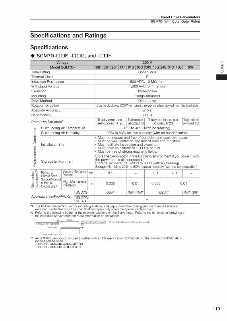
SGM7D-F, -G, and -H
*1. The hollow hole section, motor mounting surface, and gap around the rotating part on non-load side are excluded. Protective structure specifications apply only when the special cable is used.
*2. Refer to the following figure for the relevant locations on the Servomotor. Refer to the dimensional drawings of the individual Servomotors for more information on tolerances.
*3. An SGM7D Servomotor is used together with an FT-specification SERVOPACK. The following SERVOPACK models can be used.• SGD7S-AF82• SGD7S-00AF83
Voltage 200 VModel SGM7D- 30F 58F 90F 1AF 01G 05G 08G 18G 24G 34G 45G 03H
Time Rating ContinuousThermal Class FInsulation Resistance 500 VDC, 10 MΩ min.Withstand Voltage 1,500 VAC for 1 minuteExcitation Three-phaseMounting Flange-mountedDrive Method Direct driveRotation Direction Counterclockwise (CCW) for forward reference when viewed from the load sideAbsolute Accuracy ±15 sRepeatability ±1.3 s
Protective Structure*1 Totally enclosed, self-cooled, IP20
Totally enclosed, self-cooled, IP30
Totally enclosed, self-cooled, IP20
Totally enclosed, self-cooled, IP30
Env
ironm
enta
l Con
diti
ons Surrounding Air Temperature 0°C to 40°C (with no freezing)
Surrounding Air Humidity 20% to 80% relative humidity (with no condensation)
Installation Site
• Must be indoors and free of corrosive and explosive gases.• Must be well-ventilated and free of dust and moisture.• Must facilitate inspection and cleaning.• Must have an altitude of 1,000 m or less.• Must be free of strong magnetic fields.
Storage Environment
Store the Servomotor in the following environment if you store it with the power cable disconnected.Storage Temperature: -20°C to 60°C (with no freezing)Storage Humidity: 20% to 80% relative humidity (with no condensation)
Mec
hani
cal
Tole
ranc
es*2 Runout of
Output Shaft Surface/Runout at End of Output Shaft
Standard Mechanical Precision mm 0.1 – 0.1 0.1 –
High Mechanical Precision mm 0.005 0.01 0.005 0.01
Applicable SERVOPACKsSGD7S- 120A*3 2R8A*3, 2R8F*3 120A*3 2R8A*3, 2R8F*3
SGD7W-SGD7C- –
AB
Load side
Non-load side
Runout of output shaft surfaceRunout at end of output shaft
� dia.�: Diameter determined by motor model.
Direct Drive ServomotorsSGM7D (With Core, Outer Rotor)
120
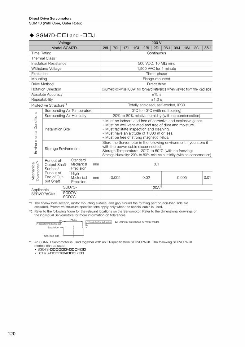
SGM7D-I and -J
*1. The hollow hole section, motor mounting surface, and gap around the rotating part on non-load side are excluded. Protective structure specifications apply only when the special cable is used.
*2. Refer to the following figure for the relevant locations on the Servomotor. Refer to the dimensional drawings of the individual Servomotors for more information on tolerances.
*3. An SGM7D Servomotor is used together with an FT-specification SERVOPACK. The following SERVOPACK models can be used.• SGD7S-AF82• SGD7S-00AF83
Voltage 200 VModel SGM7D- 28I 70I 1ZI 1CI 2BI 2DI 06J 09J 18J 20J 38J
Time Rating ContinuousThermal Class FInsulation Resistance 500 VDC, 10 MΩ min.Withstand Voltage 1,500 VAC for 1 minuteExcitation Three-phaseMounting Flange-mountedDrive Method Direct driveRotation Direction Counterclockwise (CCW) for forward reference when viewed from the load sideAbsolute Accuracy ±15 sRepeatability ±1.3 s
Protective Structure*1 Totally enclosed, self-cooled, IP30
Env
ironm
enta
l Con
diti
ons Surrounding Air Temperature 0°C to 40°C (with no freezing)
Surrounding Air Humidity 20% to 80% relative humidity (with no condensation)
Installation Site
• Must be indoors and free of corrosive and explosive gases.• Must be well-ventilated and free of dust and moisture.• Must facilitate inspection and cleaning.• Must have an altitude of 1,000 m or less.• Must be free of strong magnetic fields.
Storage Environment
Store the Servomotor in the following environment if you store it with the power cable disconnected.Storage Temperature: -20°C to 60°C (with no freezing)Storage Humidity: 20% to 80% relative humidity (with no condensation)
Mec
hani
cal
Tole
ranc
es*2 Runout of
Output Shaft Surface/Runout at End of Out-put Shaft
Standard Mechanical Precision
mm 0.1
HighMechanical Precision
mm 0.005 0.02 0.005 0.01
Applicable SERVOPACKs
SGD7S- 120A*3
SGD7W-SGD7C- –
AB
Load side
Non-load side
Runout of output shaft surfaceRunout at end of output shaft
� dia.�: Diameter determined by motor model.
Direct Drive Servomotors SGM7D (With Core, Outer Rotor)
121
SG
M7D
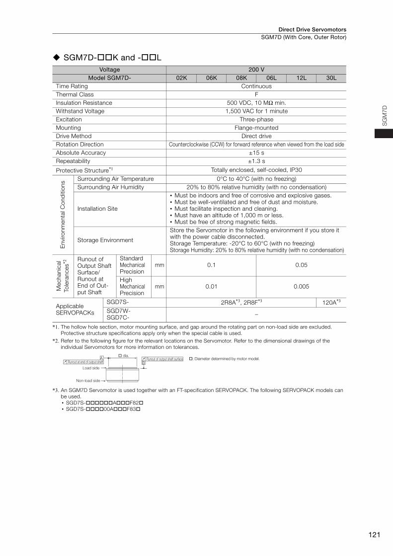
SGM7D-K and -L
*1. The hollow hole section, motor mounting surface, and gap around the rotating part on non-load side are excluded. Protective structure specifications apply only when the special cable is used.
*2. Refer to the following figure for the relevant locations on the Servomotor. Refer to the dimensional drawings of the individual Servomotors for more information on tolerances.
*3. An SGM7D Servomotor is used together with an FT-specification SERVOPACK. The following SERVOPACK models can be used.• SGD7S-AF82• SGD7S-00AF83
Voltage 200 VModel SGM7D- 02K 06K 08K 06L 12L 30L
Time Rating ContinuousThermal Class FInsulation Resistance 500 VDC, 10 MΩ min.Withstand Voltage 1,500 VAC for 1 minuteExcitation Three-phaseMounting Flange-mountedDrive Method Direct driveRotation Direction Counterclockwise (CCW) for forward reference when viewed from the load sideAbsolute Accuracy ±15 sRepeatability ±1.3 s
Protective Structure*1 Totally enclosed, self-cooled, IP30
Env
ironm
enta
l Con
diti
ons Surrounding Air Temperature 0°C to 40°C (with no freezing)
Surrounding Air Humidity 20% to 80% relative humidity (with no condensation)
Installation Site
• Must be indoors and free of corrosive and explosive gases.• Must be well-ventilated and free of dust and moisture.• Must facilitate inspection and cleaning.• Must have an altitude of 1,000 m or less.• Must be free of strong magnetic fields.
Storage Environment
Store the Servomotor in the following environment if you store it with the power cable disconnected.Storage Temperature: -20°C to 60°C (with no freezing)Storage Humidity: 20% to 80% relative humidity (with no condensation)
Mec
hani
cal
Tole
ranc
es*2 Runout of
Output Shaft Surface/Runout at End of Out-put Shaft
Standard Mechanical Precision
mm 0.1 0.05
HighMechanical Precision
mm 0.01 0.005
Applicable SERVOPACKs
SGD7S- 2R8A*3, 2R8F*3 120A*3
SGD7W-SGD7C- –
AB
Load side
Non-load side
Runout of output shaft surfaceRunout at end of output shaft
� dia.�: Diameter determined by motor model.
Direct Drive ServomotorsSGM7D (With Core, Outer Rotor)
122
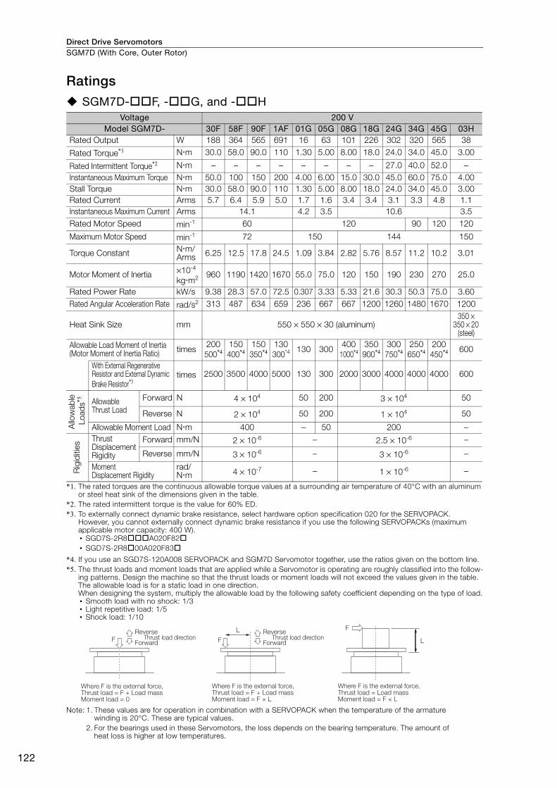
Ratings
SGM7D-F, -G, and -H
*1. The rated torques are the continuous allowable torque values at a surrounding air temperature of 40°C with an aluminum or steel heat sink of the dimensions given in the table.
*2. The rated intermittent torque is the value for 60% ED.*3. To externally connect dynamic brake resistance, select hardware option specification 020 for the SERVOPACK.
However, you cannot externally connect dynamic brake resistance if you use the following SERVOPACKs (maximum applicable motor capacity: 400 W).• SGD7S-2R8A020F82• SGD7S-2R800A020F83
*4. If you use an SGD7S-120A008 SERVOPACK and SGM7D Servomotor together, use the ratios given on the bottom line.*5. The thrust loads and moment loads that are applied while a Servomotor is operating are roughly classified into the follow-
ing patterns. Design the machine so that the thrust loads or moment loads will not exceed the values given in the table. The allowable load is for a static load in one direction.When designing the system, multiply the allowable load by the following safety coefficient depending on the type of load.• Smooth load with no shock: 1/3• Light repetitive load: 1/5• Shock load: 1/10
Note: 1. These values are for operation in combination with a SERVOPACK when the temperature of the armature winding is 20°C. These are typical values.
2. For the bearings used in these Servomotors, the loss depends on the bearing temperature. The amount of heat loss is higher at low temperatures.
Voltage 200 VModel SGM7D- 30F 58F 90F 1AF 01G 05G 08G 18G 24G 34G 45G 03H
Rated Output W 188 364 565 691 16 63 101 226 302 320 565 38
Rated Torque*1 Nm 30.0 58.0 90.0 110 1.30 5.00 8.00 18.0 24.0 34.0 45.0 3.00
Rated Intermittent Torque*2 Nm – – – – – – – – 27.0 40.0 52.0 –Instantaneous Maximum Torque Nm 50.0 100 150 200 4.00 6.00 15.0 30.0 45.0 60.0 75.0 4.00Stall Torque Nm 30.0 58.0 90.0 110 1.30 5.00 8.00 18.0 24.0 34.0 45.0 3.00Rated Current Arms 5.7 6.4 5.9 5.0 1.7 1.6 3.4 3.4 3.1 3.3 4.8 1.1Instantaneous Maximum Current Arms 14.1 4.2 3.5 10.6 3.5Rated Motor Speed min-1 60 120 90 120 120
Maximum Motor Speed min-1 72 150 144 150
Torque Constant Nm/Arms 6.25 12.5 17.8 24.5 1.09 3.84 2.82 5.76 8.57 11.2 10.2 3.01
Motor Moment of Inertia ×10-4 kgm2 960 1190 1420 1670 55.0 75.0 120 150 190 230 270 25.0
Rated Power Rate kW/s 9.38 28.3 57.0 72.5 0.307 3.33 5.33 21.6 30.3 50.3 75.0 3.60Rated Angular Acceleration Rate rad/s2 313 487 634 659 236 667 667 1200 1260 1480 1670 1200
Heat Sink Size mm 550 × 550 × 30 (aluminum)350 ×
350 × 20 (steel)
Allowable Load Moment of Inertia(Motor Moment of Inertia Ratio) times
200500*4
150400*4
150350*4
130300*4 130 300
4001000*4
350900*4
300750*4
250650*4
200450*4 600
With External Regenerative Resistor and External Dynamic Brake Resistor*3
times 2500 3500 4000 5000 130 300 2000 3000 4000 4000 4000 600
Allo
wab
le L
oads
*5 Allowable Thrust Load
Forward N 4 × 10⁴ 50 200 3 × 10⁴ 50
Reverse N 2 × 10⁴ 50 200 1 × 10⁴ 50
Allowable Moment Load Nm 400 – 50 200 –
Rig
iditi
es
Thrust Displacement Rigidity
Forward mm/N 2 × 10⁻⁶ – 2.5 × 10⁻⁶ –
Reverse mm/N 3 × 10⁻⁶ – 3 × 10⁻⁶ –
Moment Displacement Rigidity
rad/Nm 4 × 10⁻⁷ – 1 × 10⁻⁶ –
F
Where F is the external force,Thrust load = F + Load massMoment load = F × L
Where F is the external force,Thrust load = F + Load massMoment load = 0
Where F is the external force,Thrust load = Load massMoment load = F × L
Reverse
ForwardThrust load direction
Reverse
ForwardThrust load direction
F
LF
L
Direct Drive Servomotors SGM7D (With Core, Outer Rotor)
123
SG
M7
D
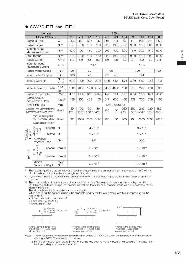
SGM7D-I and -J
*1. The rated torques are the continuous allowable torque values at a surrounding air temperature of 40°C with an aluminum heat sink of the dimensions given in the table.
*2. If you use an SGD7S-120A008 SERVOPACK and SGM7D Servomotor together, use the ratios given on the bot-tom line.
*3. The thrust loads and moment loads that are applied while a Servomotor is operating are roughly classified into the following patterns. Design the machine so that the thrust loads or moment loads will not exceed the values given in the table. The allowable load is for a static load in one direction.When designing the system, multiply the allowable load by the following safety coefficient depending on the type of load.• Smooth load with no shock: 1/3• Light repetitive load: 1/5• Shock load: 1/10
Note: 1. These values are for operation in combination with a SERVOPACK when the temperature of the armature winding is 20°C. These are typical values.
2. For the bearings used in these Servomotors, the loss depends on the bearing temperature. The amount of heat loss is higher at low temperatures.
Voltage 200 VModel SGM7D- 28I 70I 1ZI 1CI 2BI 2DI 06J 09J 18J 20J 38J
Rated Output W 264 440 628 817 691 754 75 113 226 251 358
Rated Torque*1 Nm 28.0 70.0 100 130 220 240 6.00 9.00 18.0 20.0 38.0Instantaneous Maximum Torque Nm 50.0 100 150 200 300 400 8.00 15.0 30.0 45.0 60.0
Stall Torque Nm 28.0 70.0 100 130 220 240 6.00 9.00 18.0 20.0 38.0Rated Current Arms 5.2 5.6 5.5 5.0 5.6 4.8 4.0 3.4 3.0 2.2 3.1Instantaneous Maximum Current Arms 14.1 10.6
Rated Motor Speed min-1 90 60 30 120 90
Maximum Motor Speed min-1 108 72 60 48 144
Torque Constant Nm/Arms 6.90 13.9 20.8 27.8 41.5 54.4 1.71 3.29 6.62 9.88 13.3
Motor Moment of Inertia ×10-4 kgm2 1800 2000 2300 2850 3400 4000 150 210 240 260 330
Rated Power Rate kW/s 4.36 24.5 43.5 59.3 142 144 2.40 3.86 13.5 15.4 43.8Rated Angular Acceleration Rate rad/s2 156 350 435 456 647 600 400 429 750 769 1150
Heat Sink Size mm 550 × 550 × 30Allowable Load Moment of Inertia(Motor Moment of Inertia Ratio) times
50125*2
100250*2
90230*2
80200*2 100 150
350700*2
250600*2
240550*2
220550*2
180450*2
With External Regenera-tive Resistor and External Dynamic Brake Resistor*3
times 800 2000 2500 3000 100 150 700 900 2500 2000 2000
Allo
wab
le L
oads
*3
Allow
able
Thru
st L
oad Forward N 4 × 10⁴ 3 × 10⁴
Reverse N 2 × 10⁴ 1 × 10⁴
Allowable Moment Load Nm 400 200
Rig
iditi
es
Thru
st D
isplac
emen
t R
igidi
ty Forward mm/N 2 × 10⁻⁶ 3 × 10⁻⁶
Reverse mm/N 3 × 10⁻⁶ 4 × 10⁻⁶
Moment Displacement Rigidity
rad/Nm 4 × 10⁻⁷ 2 × 10⁻⁶
F
Where F is the external force,Thrust load = F + Load massMoment load = F × L
Where F is the external force,Thrust load = F + Load massMoment load = 0
Where F is the external force,Thrust load = Load massMoment load = F × L
Reverse
ForwardThrust load direction
Reverse
ForwardThrust load direction
F
LF
L
Direct Drive ServomotorsSGM7D (With Core, Outer Rotor)
124
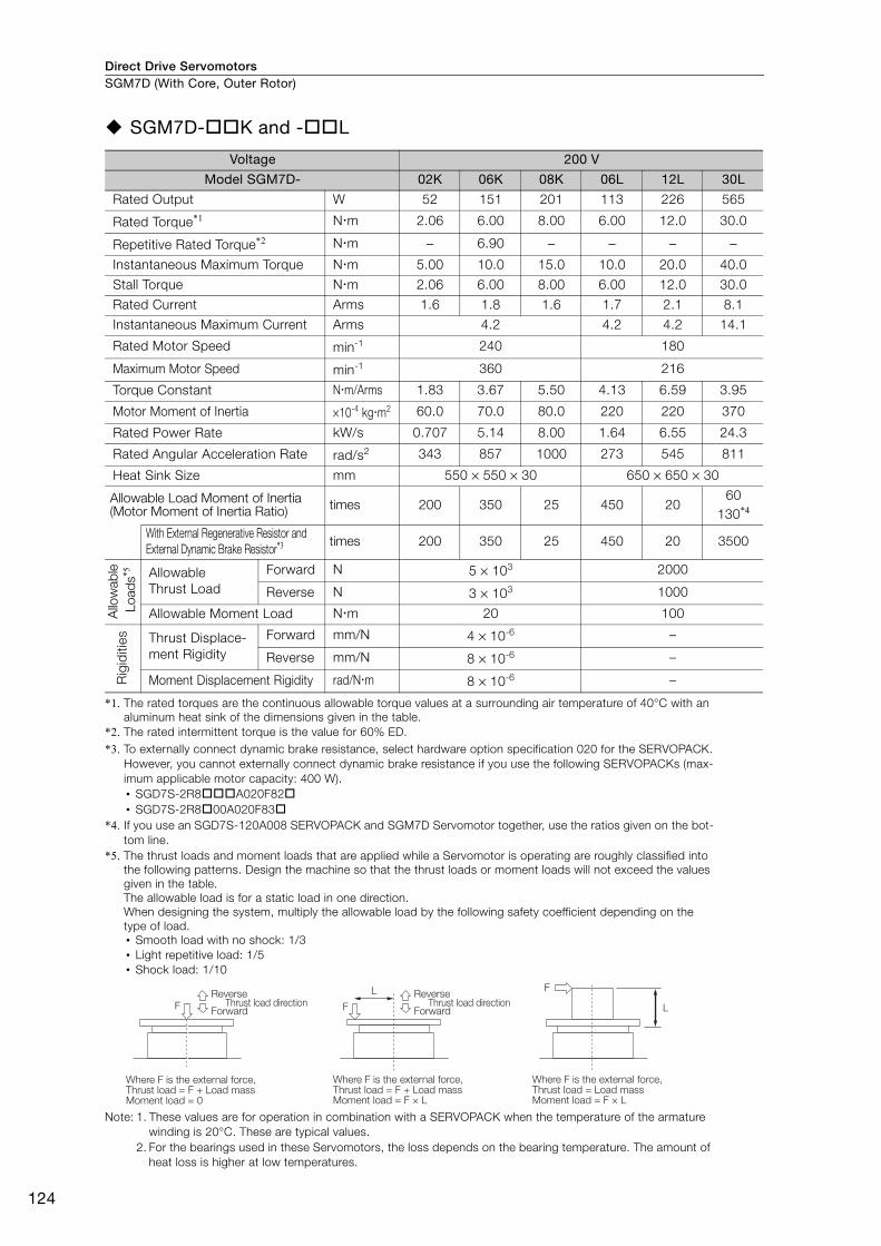
SGM7D-K and -L
*1. The rated torques are the continuous allowable torque values at a surrounding air temperature of 40°C with an aluminum heat sink of the dimensions given in the table.
*2. The rated intermittent torque is the value for 60% ED.*3. To externally connect dynamic brake resistance, select hardware option specification 020 for the SERVOPACK.
However, you cannot externally connect dynamic brake resistance if you use the following SERVOPACKs (max-imum applicable motor capacity: 400 W).• SGD7S-2R8A020F82• SGD7S-2R800A020F83
*4. If you use an SGD7S-120A008 SERVOPACK and SGM7D Servomotor together, use the ratios given on the bot-tom line.
*5. The thrust loads and moment loads that are applied while a Servomotor is operating are roughly classified into the following patterns. Design the machine so that the thrust loads or moment loads will not exceed the values given in the table. The allowable load is for a static load in one direction.When designing the system, multiply the allowable load by the following safety coefficient depending on the type of load.• Smooth load with no shock: 1/3• Light repetitive load: 1/5• Shock load: 1/10
Note: 1. These values are for operation in combination with a SERVOPACK when the temperature of the armature winding is 20°C. These are typical values.
2. For the bearings used in these Servomotors, the loss depends on the bearing temperature. The amount of heat loss is higher at low temperatures.
Voltage 200 V
Model SGM7D- 02K 06K 08K 06L 12L 30L
Rated Output W 52 151 201 113 226 565
Rated Torque*1 Nm 2.06 6.00 8.00 6.00 12.0 30.0
Repetitive Rated Torque*2 Nm − 6.90 − − − −Instantaneous Maximum Torque Nm 5.00 10.0 15.0 10.0 20.0 40.0
Stall Torque Nm 2.06 6.00 8.00 6.00 12.0 30.0
Rated Current Arms 1.6 1.8 1.6 1.7 2.1 8.1
Instantaneous Maximum Current Arms 4.2 4.2 4.2 14.1
Rated Motor Speed min-1 240 180
Maximum Motor Speed min-1 360 216
Torque Constant Nm/Arms 1.83 3.67 5.50 4.13 6.59 3.95
Motor Moment of Inertia ×10-4 kgm2 60.0 70.0 80.0 220 220 370
Rated Power Rate kW/s 0.707 5.14 8.00 1.64 6.55 24.3
Rated Angular Acceleration Rate rad/s2 343 857 1000 273 545 811
Heat Sink Size mm 550 × 550 × 30 650 × 650 × 30
Allowable Load Moment of Inertia(Motor Moment of Inertia Ratio) times 200 350 25 450 20
60130*4
With External Regenerative Resistor and External Dynamic Brake Resistor*3 times 200 350 25 450 20 3500
Allo
wab
le L
oads
*5 Allowable Thrust Load
Forward N 5 × 10³ 2000
Reverse N 3 × 10³ 1000
Allowable Moment Load Nm 20 100
Rig
iditi
es Thrust Displace-ment Rigidity
Forward mm/N 4 × 10⁻⁶ –
Reverse mm/N 8 × 10⁻⁶ –
Moment Displacement Rigidity rad/Nm 8 × 10⁻⁶ –
F
Where F is the external force,Thrust load = F + Load massMoment load = F × L
Where F is the external force,Thrust load = F + Load massMoment load = 0
Where F is the external force,Thrust load = Load massMoment load = F × L
Reverse
ForwardThrust load direction
Reverse
ForwardThrust load direction
F
LF
L
Direct Drive Servomotors SGM7D (With Core, Outer Rotor)
125
SG
M7
D
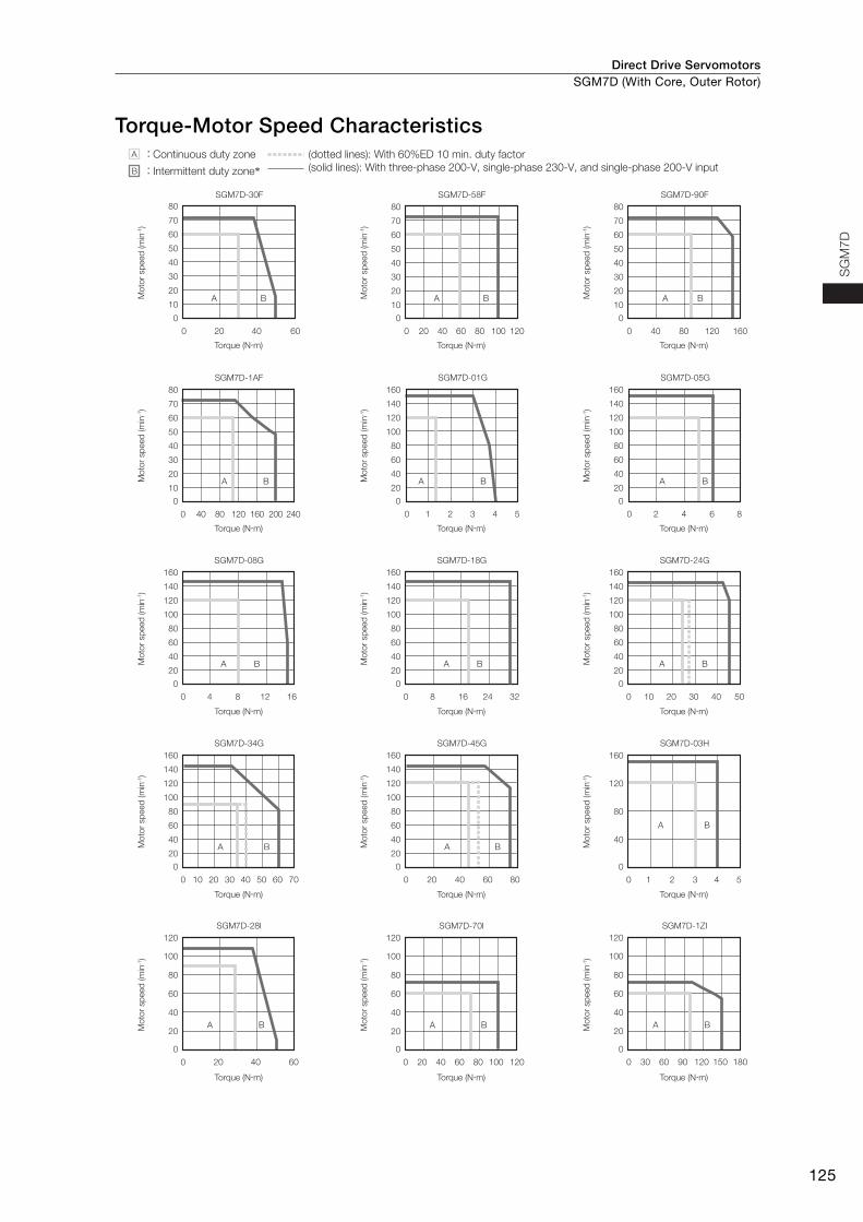
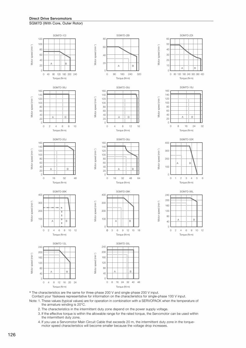
Torque-Motor Speed CharacteristicsA : Continuous duty zone (dotted lines): With 60%ED 10 min. duty factor
(solid lines): With three-phase 200-V, single-phase 230-V, and single-phase 200-V inputB : Intermittent duty zone*
A
0 20 40 60 80
0
B20
40
60
80
100
120
140
160
A
0 20 30 40 50 60 7010
0
B20
40
60
80
100
120
140
160
A
0 10 20 30 40 50
0
B20
40
60
80
100
120
140
160
A
0 8 16 24 32
0
B20
40
60
80
100
120
140
160
A
0 4 8 12 16
0
B20
40
60
80
100
120
140
160
A
0 2 4 6 8
0
B20
40
60
80
100
120
140
160
A
0 1 2 3 4 5
0
B20
40
60
80
100
120
140
160
A
0 1 2 3 4 5
0
B
40
80
120
160
A
0 20 40 60
0
10
A
0 8040 120 160 200 240
0
B10
20
30
40
50
60
70
80
A
0 40 80 120 160
0
B10
20
30
40
50
60
70
80
A
0 20 40 60 80 100 120
0
B10
20
30
40
50
60
70
80
20
30
40
50
60
70
80
B
A
0 20 40
0
B20
40
60
120
80
100
60
A
0 4020 8060
0
B20
40
60
120
80
100
120100
A
0 6030 12090
0
B20
40
60
120
80
100
180150
SGM7D-30F SGM7D-90FSGM7D-58F
SGM7D-05GSGM7D-01GSGM7D-1AF
Torque (N�m)
SGM7D-24GSGM7D-18GSGM7D-08G
SGM7D-45GSGM7D-34G SGM7D-03H
SGM7D-28I SGM7D-70I SGM7D-1ZI
Mo
tor
sp
eed
(m
in-1)
Torque (N�m)
Mo
tor
sp
eed
(m
in-1)
Torque (N�m)
Mo
tor
sp
eed
(m
in-1)
Torque (N�m)
Mo
tor
sp
eed
(m
in-1)
Torque (N�m)
Mo
tor
sp
eed
(m
in-1)
Torque (N�m)
Mo
tor
sp
eed
(m
in-1)
Torque (N�m)
Mo
tor
sp
eed
(m
in-1)
Torque (N�m)
Mo
tor
sp
eed
(m
in-1)
Torque (N�m)
Mo
tor
sp
eed
(m
in-1)
Torque (N�m)
Mo
tor
sp
eed
(m
in-1)
Torque (N�m)
Mo
tor
sp
eed
(m
in-1)
Torque (N�m)
Mo
tor
sp
eed
(m
in-1)
Torque (N�m)
Mo
tor
sp
eed
(m
in-1)
Torque (N�m)
Mo
tor
sp
eed
(m
in-1)
Torque (N�m)
Mo
tor
sp
eed
(m
in-1)
Direct Drive ServomotorsSGM7D (With Core, Outer Rotor)
126
* The characteristics are the same for three-phase 200 V and single-phase 200 V input.Contact your Yaskawa representative for information on the characteristics for single-phase 100 V input.
Note: 1. These values (typical values) are for operation in combination with a SERVOPACK when the temperature of the armature winding is 20°C.
2. The characteristics in the intermittent duty zone depend on the power supply voltage.3. If the effective torque is within the allowable range for the rated torque, the Servomotor can be used within
the intermittent duty zone.4. If you use a Servomotor Main Circuit Cable that exceeds 20 m, the intermittent duty zone in the torque-
motor speed characteristics will become smaller because the voltage drop increases.
A
0 4 62 108
B
SGM7D-06J
A
0 4 8 12 16
B
SGM7D-09J
A
8 16 24 32
B
SGM7D-18J
A
0 16 4832
B
SGM7D-20J
A
0 16 644832
B
SGM7D-38J SGM7D-02K
SGM7D-1CI SGM7D-2BI SGM7D-2DI
SGM7D-06LSGM7D-08KSGM7D-06K
0
A
0 8040 160120
0
B20
40
60
120
80
100
240200
A
0 16080 320240
0
B20
40
80
60
A
0 18060 120 420240 300 360
0B
10
20
30
60
40
50
A
0 1 2 3 4 5 6
0
B
400
300
200
100
A
0 2 4 6 8 10
0
B40
80
120
240
160
200
12
A
0 4 8 12 16 20
0
B40
80
120
240
160
200
24
A
0 8 16 24 32 40
0
B40
80
120
240
160
200
48
A
0
400
300
200
100BA
0 42 8 106 12
0
400
300
200
100B
00 63 12 159 18
0
20
40
60
160
140
120
80
100
0
20
40
60
160
140
120
80
100
0
20
40
60
160
140
120
80
100
0
20
40
60
160
140
120
80
100
0
20
40
60
160
140
120
80
100
SGM7D-12L SGM7D-30L
Torque (N�m)
Mo
tor
sp
eed
(m
in-1)
Torque (N�m)
Mo
tor
sp
eed
(m
in-1)
Torque (N�m)
Mo
tor
sp
eed
(m
in-1)
Torque (N�m)
Mo
tor
sp
eed
(m
in-1)
Torque (N�m)
Mo
tor
sp
eed
(m
in-1)
Torque (N�m)
Mo
tor
sp
eed
(m
in-1)
Torque (N�m)
Mo
tor
sp
eed
(m
in-1)
Torque (N�m)
Mo
tor
sp
eed
(m
in-1)
Torque (N�m)
Mo
tor
sp
eed
(m
in-1)
Torque (N�m)
Mo
tor
sp
eed
(m
in-1)
Torque (N�m)
Mo
tor
sp
eed
(m
in-1)
Torque (N�m)
Mo
tor
sp
eed
(m
in-1)
Torque (N�m)
Mo
tor
sp
eed
(m
in-1)
Torque (N�m)
Mo
tor
sp
eed
(m
in-1)
Direct Drive Servomotors SGM7D (With Core, Outer Rotor)
127
SG
M7
D
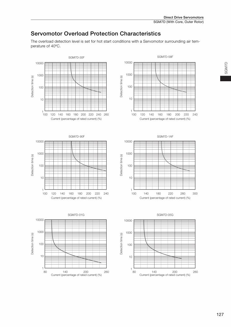
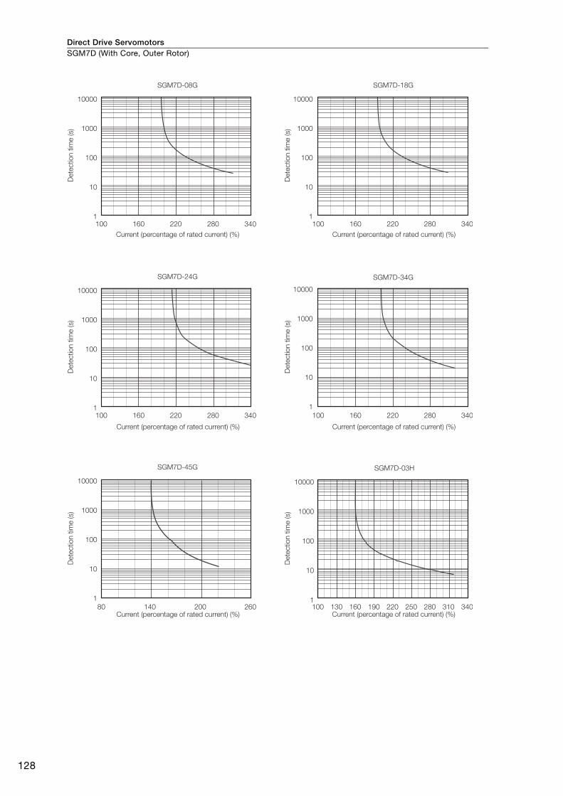
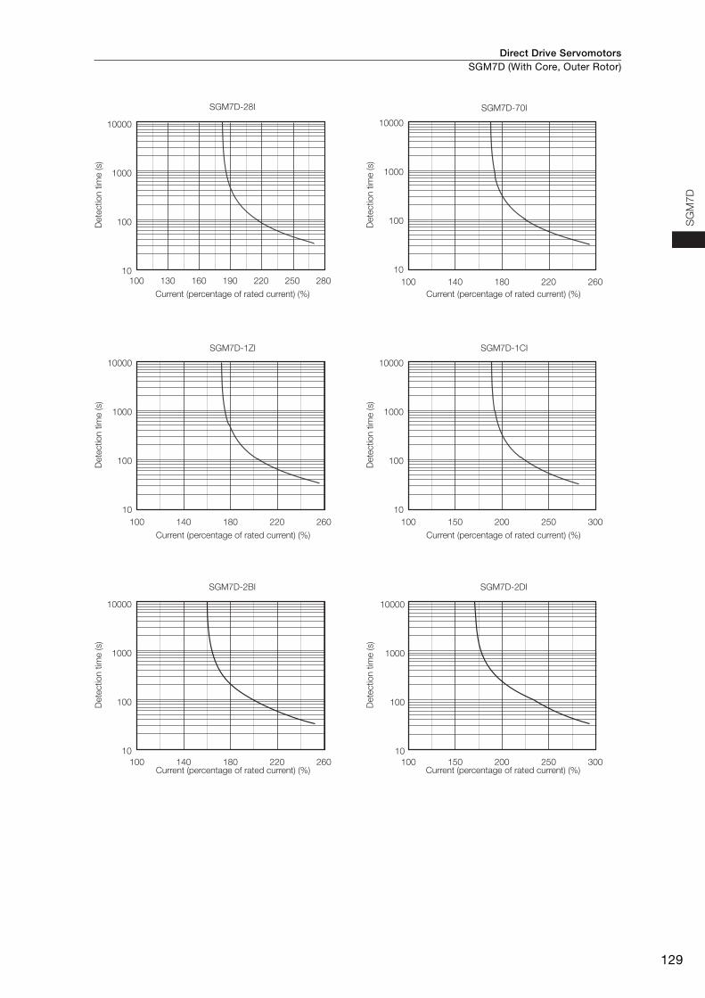
Servomotor Overload Protection CharacteristicsThe overload detection level is set for hot start conditions with a Servomotor surrounding air tem-perature of 40ºC.
SGM7D-30F
100 120 260240220200160140 180
10000
1000
100
10
1
SGM7D-58F
100 120 140 240220200160 180
100 120 140 240220200160 180
10000
1000
100
10
1
SGM7D-90F
10000
1000
100
10
1
SGM7D-1AF
100 300180140 260220
10000
1000
100
10
1
SGM7D-01G
80 260140 200 80 260140 200
10000
1000
100
10
1
SGM7D-05G
10000
1000
100
10
1
Current (percentage of rated current) (%) Current (percentage of rated current) (%)
Current (percentage of rated current) (%) Current (percentage of rated current) (%)
Current (percentage of rated current) (%) Current (percentage of rated current) (%)
Dete
ctio
n t
ime (s)
Dete
ctio
n t
ime (s)
Dete
ctio
n t
ime (s)
Dete
ctio
n t
ime (s)
Dete
ctio
n t
ime (s)
Dete
ctio
n t
ime (s)
Direct Drive ServomotorsSGM7D (With Core, Outer Rotor)
128
SGM7D-08G
340
10000
1000
100
10
1
SGM7D-18G
10000
1000
100
10
1
SGM7D-34G
10000
1000
100
10
1
SGM7D-24G
SGM7D-45G
10000
1000
100
10
1
100 160 220 280 340100 160 220 280
340100 160 220 280 340100 160 220 280
10000
1000
100
10
1
26080 140 200
SGM7D-03H
100 130 340310280250220160 190
10000
1000
100
10
1
Current (percentage of rated current) (%) Current (percentage of rated current) (%)
Current (percentage of rated current) (%) Current (percentage of rated current) (%)
Current (percentage of rated current) (%) Current (percentage of rated current) (%)
Dete
ctio
n t
ime (s)
Dete
ctio
n t
ime (s)
Dete
ctio
n t
ime (s)
Dete
ctio
n t
ime (s)
Dete
ctio
n t
ime (s)
Dete
ctio
n t
ime (s)
Direct Drive Servomotors SGM7D (With Core, Outer Rotor)
129
SG
M7
D
SGM7D-28I
100 130 280250160 190 220
10000
1000
100
10
SGM7D-1CI
100 150 300250200
10000
1000
100
10
SGM7D-2BI
SGM7D-1ZI
100 140 260220180
100 150 300250200100 140 260220180
10000
1000
100
10
SGM7D-70I
100 140 260220180
10000
1000
100
10
SGM7D-2DI
10000
1000
100
10
10000
1000
100
10
Current (percentage of rated current) (%) Current (percentage of rated current) (%)
Current (percentage of rated current) (%) Current (percentage of rated current) (%)
Current (percentage of rated current) (%) Current (percentage of rated current) (%)
Dete
ctio
n t
ime (s)
Dete
ctio
n t
ime (s)
Dete
ctio
n t
ime (s)
Dete
ctio
n t
ime (s)
Dete
ctio
n t
ime (s)
Dete
ctio
n t
ime (s)
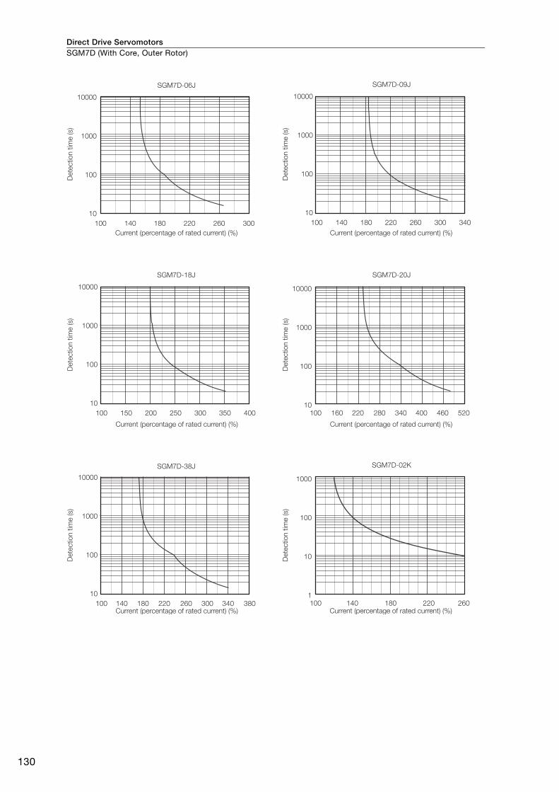
Direct Drive ServomotorsSGM7D (With Core, Outer Rotor)
130
SGM7D-06J
100 140 300260220180
10000
1000
100
10
SGM7D-20J
100 220160 520400 460280 340
10000
1000
100
10
SGM7D-09J
100 340220 260 300180140
10000
1000
100
10
SGM7D-18J
100 150 400350200 300250
10000
1000
100
10
SGM7D-38J
100 140 380340180 220 260 300
10000
1000
100
10
SGM7D-02K
100 260220180140
1000
100
10
1
Current (percentage of rated current) (%) Current (percentage of rated current) (%)
Current (percentage of rated current) (%) Current (percentage of rated current) (%)
Current (percentage of rated current) (%) Current (percentage of rated current) (%)
Dete
ctio
n t
ime (s)
Dete
ctio
n t
ime (s)
Dete
ctio
n t
ime (s)
Dete
ctio
n t
ime (s)
Dete
ctio
n t
ime (s)
Dete
ctio
n t
ime (s)
Direct Drive Servomotors SGM7D (With Core, Outer Rotor)
131
SG
M7
D
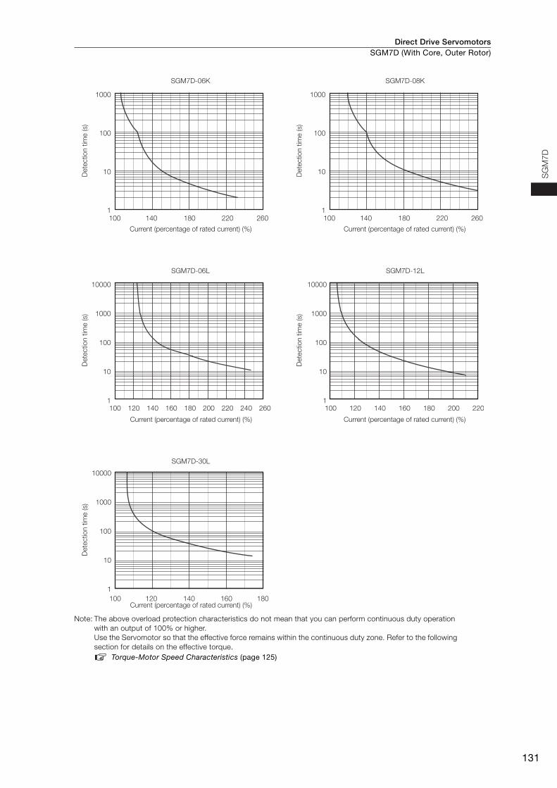
Note: The above overload protection characteristics do not mean that you can perform continuous duty operation with an output of 100% or higher.Use the Servomotor so that the effective force remains within the continuous duty zone. Refer to the following section for details on the effective torque.
Torque-Motor Speed Characteristics (page 125)
SGM7D-06L
100 120 260240220200180160140
10000
1000
100
10
1
SGM7D-12L
100 120 140 160 180 200 220
10000
1000
100
10
1
SGM7D-30L
100 180160140120
10000
1000
100
10
1
SGM7D-08K
100 260220180140
1000
100
10
1
SGM7D-06K
100 260220180140
1000
100
10
1
Current (percentage of rated current) (%) Current (percentage of rated current) (%)
Current (percentage of rated current) (%) Current (percentage of rated current) (%)
Current (percentage of rated current) (%)
Dete
ctio
n t
ime (s)
Dete
ctio
n t
ime (s)
Dete
ctio
n t
ime (s)
Dete
ctio
n t
ime (s)
Dete
ctio
n t
ime (s)

Direct Drive ServomotorsSGM7D (With Core, Outer Rotor)
132
Allowable Load Moment of InertiaThe allowable load moments of inertia (motor moment of inertia ratios) for the Servomotors are given in the Ratings (pages 122 to 124). The values are determined by the regenerative energy processing capacity of the SERVOPACK and are also affected by the drive conditions of the Servomotor. Per-form the required Steps for each of the following cases.
Use the SigmaSize+ AC Servo Drive Capacity Selection Program to check the driving conditions. Contact your Yaskawa representative for information on this program.
Exceeding the Allowable Load Moment of InertiaUse one of the following measures to adjust the load moment of inertia to within the allowable value.• Reduce the torque limit.• Reduce the deceleration rate.• Reduce the maximum motor speed.
If the above steps is not possible, install an external regenerative resistor.
When an External Regenerative Resistor Is RequiredInstall the External Regenerative Resistor. Refer to the following section for the recommended products.
External Regenerative Resistors (page 472)
An Overvoltage Alarm (A.400) is likely to occur during deceleration if the load moment of iner-tia exceeds the allowable load moment of inertia. SERVOPACKs with a built-in regenerative resistor may generate a Regenerative Overload Alarm (A.320). Refer to Built-In Regenerative Resistor (page 472) for the regenerative power (W) that can be processed by the SERVO-PACKs.Install an External Regenerative Resistor when the built-in regenerative resistor cannot process all of the regenerative power.
Information
Direct Drive Servomotors SGM7D (With Core, Outer Rotor)
133
SG
M7
D
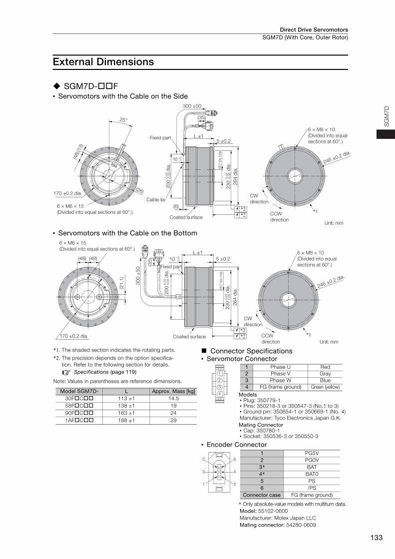
External Dimensions
SGM7D-F• Servomotors with the Cable on the Side
• Servomotors with the Cable on the Bottom
*1. The shaded section indicates the rotating parts.
*2. The precision depends on the option specifica-tion. Refer to the following section for details.
Specifications (page 119)
Note: Values in parentheses are reference dimensions.
Connector Specifications• Servomotor Connector
Models• Plug: 350779-1• Pins: 350218-3 or 350547-3 (No.1 to 3)• Ground pin: 350654-1 or 350669-1 (No. 4)Manufacturer: Tyco Electronics Japan G.K.Mating Connector• Cap: 350780-1• Socket: 350536-3 or 350550-3
• Encoder Connector
* Only absolute-value models with multiturn data.Model: 55102-0600Manufacturer: Molex Japan LLCMating connector: 54280-0609
Unit: mm
CW
direction
6 × M8 × 10
(Divided into equal
sections at 60°.)
CCW
direction
246 ±0.2 dia.
*1
25°
(13)
(48)
6 × M6 × 15
(Divided into equal sections at 60°.)Coated surface
5 ±0.2L ±1Fixed part
26
4 d
ia.
23
0
dia
.-0
.02
-0.0
6
+0.
50
(6)
20
0
dia
.-0
.02
-0.0
5
*2*2
170 ±0.2 dia.
58
dia
. ho
le
300 ±50
(35)
Cable tie
(26)
10 +20
Unit: mm
CW
direction
6 × M8 × 10
(Divided into equal
sections at 60°.)
CCW
direction
246 ±0.2 dia.
*1
6 × M6 × 15
(Divided into equal sections at 60°.)
170 ±0.2 dia.
(21
.1)
(48) (48) 5 ±0.210+2
0
L ±1
Fixed part
23
0
dia
.-0
.02
-0.0
6
Coated surface
20
0
dia
.-0
.02
-0.0
5
*2*2
+0.
50
58 d
ia. hole
26
4 d
ia.
30
0 ±
50
(35
)
Model SGM7D- L Approx. Mass [kg]30FC 113 ±1 14.558FC 138 ±1 1990FC 163 ±1 241AFC 188 ±1 29
1
2
3
4
1 Phase U Red2 Phase V Gray3 Phase W Blue4 FG (frame ground) Green (yellow)
4
2
6
3
1
5
1 PG5V2 PG0V3* BAT4* BAT05 PS6 /PS
Connector case FG (frame ground)
Direct Drive ServomotorsSGM7D (With Core, Outer Rotor)
134
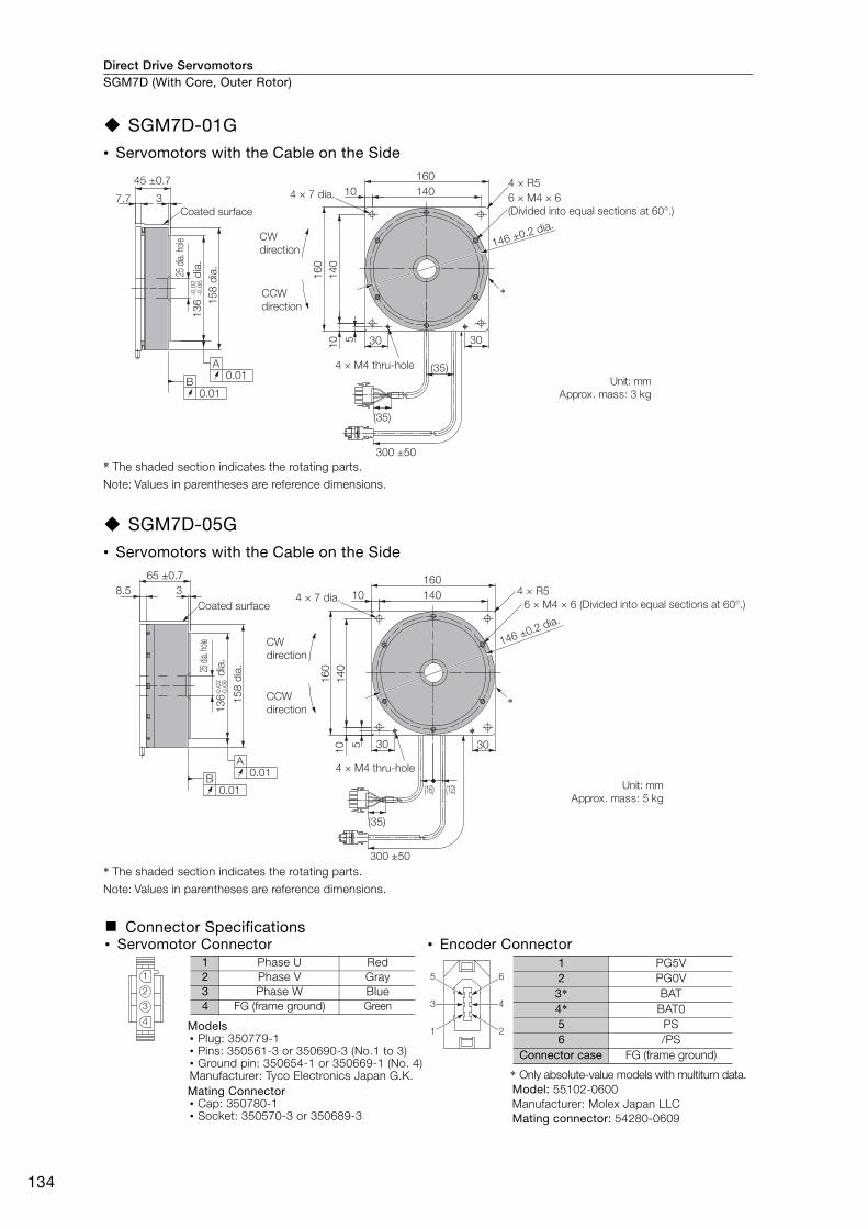
SGM7D-01G• Servomotors with the Cable on the Side
* The shaded section indicates the rotating parts.
Note: Values in parentheses are reference dimensions.
SGM7D-05G• Servomotors with the Cable on the Side
* The shaded section indicates the rotating parts.
Note: Values in parentheses are reference dimensions.
Connector Specifications• Servomotor Connector • Encoder Connector
Models• Plug: 350779-1• Pins: 350561-3 or 350690-3 (No.1 to 3)• Ground pin: 350654-1 or 350669-1 (No. 4)Manufacturer: Tyco Electronics Japan G.K.Mating Connector• Cap: 350780-1• Socket: 350570-3 or 350689-3
* Only absolute-value models with multiturn data.Model: 55102-0600Manufacturer: Molex Japan LLCMating connector: 54280-0609
Unit: mm
Approx. mass: 3 kg
*
15
8 d
ia.
13
6
dia
.-0
.02
-0.0
6
Coated surface
45 ±0.7
37.7 6 × M4 × 6
(Divided into equal sections at 60°.)
4 × 7 dia.
CW
direction
CCW
direction
160
140104 × R5
16
0
14
01
0 5 30 30
146 ±0.2 dia.
(35)4 × M4 thru-hole
0.01B
0.01A
25 d
ia. h
ole
300 ±50
(35)
Unit: mm
Approx. mass: 5 kg
65 ±0.7
8.5
13
6
dia
.-0
.02
-0.0
6
Coated surface
3
6 × M4 × 6 (Divided into equal sections at 60°.)
4 × R5
146 ±0.2 dia.
4 × 7 dia.
160
14010
CW
direction
CCW
direction
16
0
14
01
0 5 30 30
(16) (12)
4 × M4 thru-hole
*
0.01A
0.01B
25 d
ia. h
ole
15
8 d
ia.
300 ±50
(35)
1
2
3
4
1 Phase U Red2 Phase V Gray3 Phase W Blue4 FG (frame ground) Green 4
2
6
3
1
5
1 PG5V2 PG0V3* BAT4* BAT05 PS6 /PS
Connector case FG (frame ground)
Direct Drive Servomotors SGM7D (With Core, Outer Rotor)
135
SG
M7
D
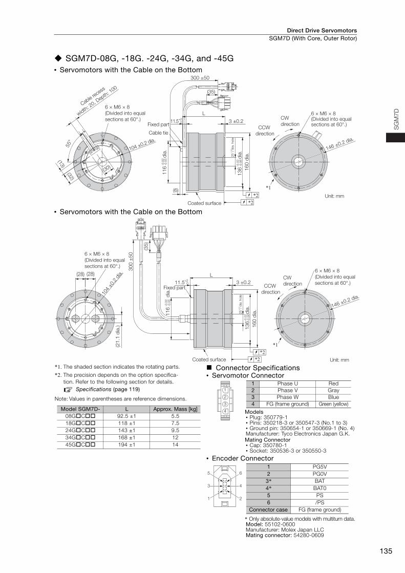
SGM7D-08G, -18G. -24G, -34G, and -45G• Servomotors with the Cable on the Bottom
• Servomotors with the Cable on the Bottom
*1. The shaded section indicates the rotating parts.
*2. The precision depends on the option specifica-tion. Refer to the following section for details.
Specifications (page 119)
Note: Values in parentheses are reference dimensions.
Connector Specifications• Servomotor Connector
Models• Plug: 350779-1• Pins: 350218-3 or 350547-3 (No.1 to 3)• Ground pin: 350654-1 or 350669-1 (No. 4)Manufacturer: Tyco Electronics Japan G.K.Mating Connector• Cap: 350780-1• Socket: 350536-3 or 350550-3
• Encoder Connector
* Only absolute-value models with multiturn data.Model: 55102-0600Manufacturer: Molex Japan LLCMating connector: 54280-0609
Unit: mm
CW
directionCCW
direction
*1
146 ±0.2 dia.
6 × M6 × 8 (Divided into equal sections at 60°.)
L
3 ±0.211.5+2
0
16
0 d
ia.
13
6
dia
.-0
.02
-0.0
6
11
6
dia
.-0
.02
-0.0
5
(6)
Coated surface
(13)
(32)
55°
(30)
104 ±0.2 dia.
Cable recess
width: 2
0, Depth
: 100
6 × M6 × 8
(Divided into equal
sections at 60°.)Fixed part
Cable tie
*2*2
-0.0
20
25 d
ia. hole
300 ±50
(35)
Unit: mm
(21
.1 d
ia.)
104
±0.
2 di
a.
6 × M6 × 8
(Divided into equal
sections at 60°.)
(28) (28)
16
0 d
ia.
13
6
d
ia.
-0.0
2-0
.06
Coated surface
L
3 ±0.211.5+2
0
Fixed part
11
6
dia
.-0
.02
-0.0
5
*2*2
CCW
direction
CW
direction
6 × M6 × 8
(Divided into equal
sections at 60°.)
146 ±0.2 dia.
*1
+0.
50
25 d
ia. hole
30
0 ±
50
(35
)
Model SGM7D- L Approx. Mass [kg]08GC 92.5 ±1 5.518GC 118 ±1 7.524GC 143 ±1 9.534GC 168 ±1 1245GC 194 ±1 14
1
2
3
4
1 Phase U Red2 Phase V Gray3 Phase W Blue4 FG (frame ground) Green (yellow)
4
2
6
3
1
5
1 PG5V2 PG0V3* BAT4* BAT05 PS6 /PS
Connector case FG (frame ground)
Direct Drive ServomotorsSGM7D (With Core, Outer Rotor)
136
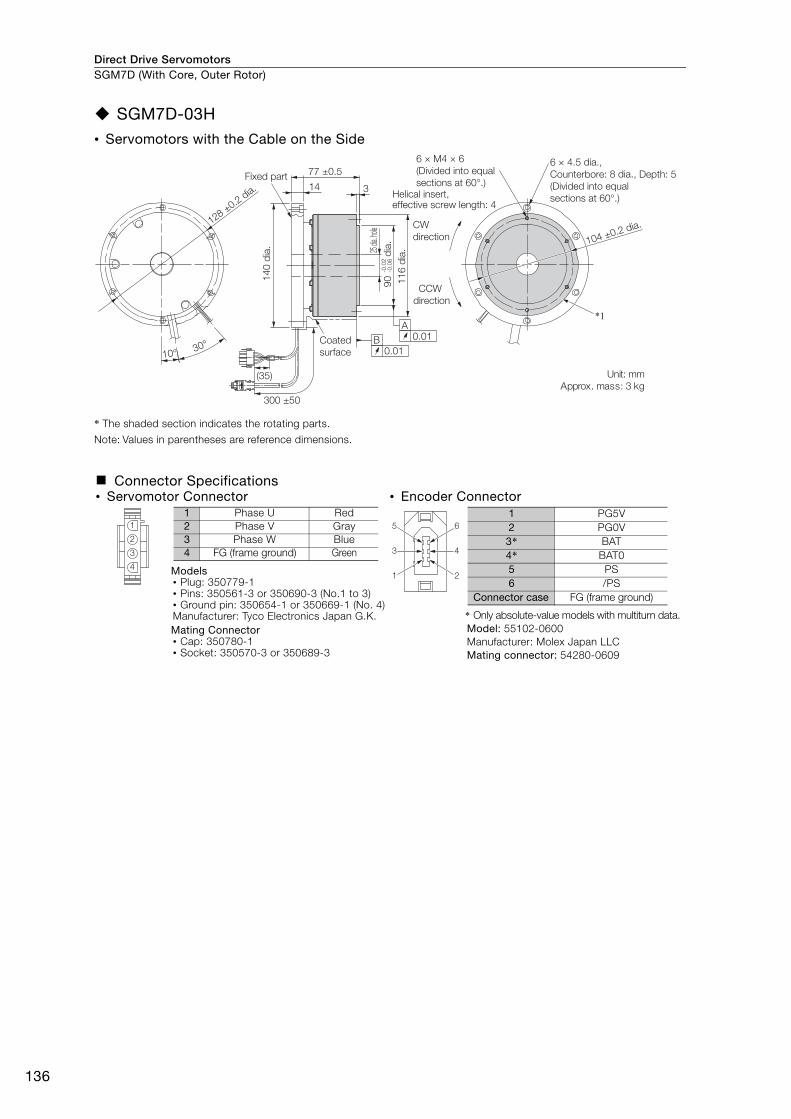
SGM7D-03H• Servomotors with the Cable on the Side
* The shaded section indicates the rotating parts.
Note: Values in parentheses are reference dimensions.
Connector Specifications• Servomotor Connector • Encoder Connector
Models• Plug: 350779-1• Pins: 350561-3 or 350690-3 (No.1 to 3)• Ground pin: 350654-1 or 350669-1 (No. 4)Manufacturer: Tyco Electronics Japan G.K.Mating Connector• Cap: 350780-1• Socket: 350570-3 or 350689-3
* Only absolute-value models with multiturn data.Model: 55102-0600Manufacturer: Molex Japan LLCMating connector: 54280-0609
*1
10° 30°
77 ±0.5
14 3
0.01A
0.01B
300 ±50
(35) Unit: mm
Approx. mass: 3 kg
Coated
surface
CCW
direction
CW
direction
Fixed part
14
0 d
ia. 25 di
a. ho
le-0
.02
-0.0
69
0
dia
.
11
6 d
ia.
6 × M4 × 6
(Divided into equal
sections at 60°.)
6 × 4.5 dia.,
Counterbore: 8 dia., Depth: 5
(Divided into equal
sections at 60°.)
104 ±0.2 dia.
Helical insert, effective screw length: 4
128 ±0.2
dia.
1
2
3
4
1 Phase U Red2 Phase V Gray3 Phase W Blue4 FG (frame ground) Green 4
2
6
3
1
5
1 PG5V2 PG0V3* BAT4* BAT05 PS6 /PS
Connector case FG (frame ground)
Direct Drive Servomotors SGM7D (With Core, Outer Rotor)
137
SG
M7
D
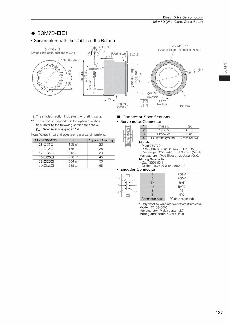
SGM7D-I
• Servomotors with the Cable on the Bottom
*1. The shaded section indicates the rotating parts.
*2. The precision depends on the option specifica-tion. Refer to the following section for details.
Specifications (page 119)
Note: Values in parentheses are reference dimensions.
Connector Specifications• Servomotor Connector
Models• Plug: 350779-1• Pins: 350218-3 or 350547-3 (No.1 to 3)• Ground pin: 350654-1 or 350669-1 (No. 4)Manufacturer: Tyco Electronics Japan G.K.Mating Connector• Cap: 350780-1• Socket: 350536-3 or 350550-3
• Encoder Connector
* Only absolute-value models with multiturn data.Model: 55102-0600Manufacturer: Molex Japan LLCMating connector: 54280-0609
*2*2
*1
(35
)3
00
±5
0
300 ±50
(88
)(8
8)
L
5 ±0.211.5
+20
79
230 ±0.2 dia.
Rotating part
CW
direction
CCW
direction
170 ±0.2 dia.
21
5
dia
.-0
.02
-0.0
6
(15
0 d
ia.) h
ole
25
2 d
ia.
Coated surface
26
4 d
ia.
19
2
dia
.-0
.02
-0.0
5
Fixed part
Unit: mm
6 × M8 × 12
(Divided into equal sections at 60°.)
6 × M8 × 12
(Divided into equal sections at 60°.)
Model SGM7D- L Approx. Mass [kg]28IC5 158 ±1 2370IC5 185 ±1 281ZIC5 212 ±1 331CIC5 250 ±1 452BIC5 304 ±1 552DIC5 358 ±1 65
1
2
3
4
1 Phase U Red2 Phase V Gray3 Phase W Blue4 FG (frame ground) Green (yellow)
4
2
6
3
1
5
1 PG5V2 PG0V3* BAT4* BAT05 PS6 /PS
Connector case FG (frame ground)
Direct Drive ServomotorsSGM7D (With Core, Outer Rotor)
138
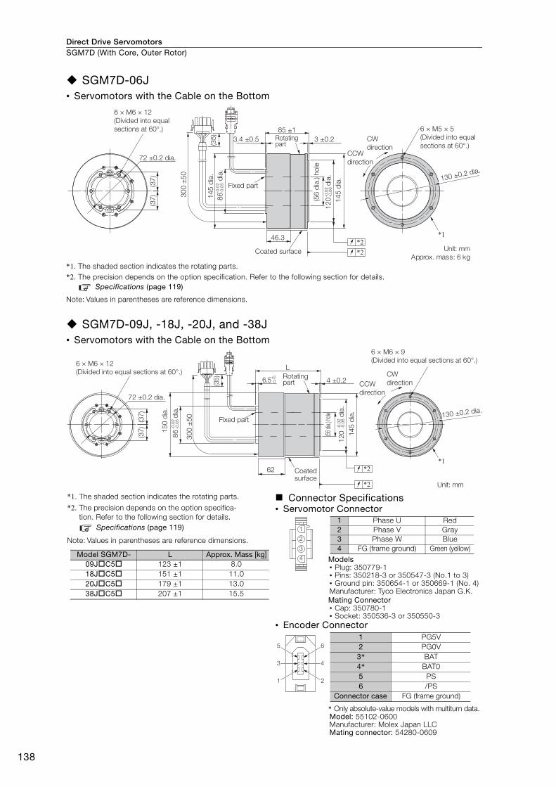
SGM7D-06J• Servomotors with the Cable on the Bottom
*1. The shaded section indicates the rotating parts.*2. The precision depends on the option specification. Refer to the following section for details.
Specifications (page 119)
Note: Values in parentheses are reference dimensions.
SGM7D-09J, -18J, -20J, and -38J• Servomotors with the Cable on the Bottom
*1. The shaded section indicates the rotating parts.
*2. The precision depends on the option specifica-tion. Refer to the following section for details.
Specifications (page 119)
Note: Values in parentheses are reference dimensions.
Connector Specifications• Servomotor Connector
Models• Plug: 350779-1• Pins: 350218-3 or 350547-3 (No.1 to 3)• Ground pin: 350654-1 or 350669-1 (No. 4)Manufacturer: Tyco Electronics Japan G.K.Mating Connector• Cap: 350780-1• Socket: 350536-3 or 350550-3
• Encoder Connector
* Only absolute-value models with multiturn data.Model: 55102-0600Manufacturer: Molex Japan LLCMating connector: 54280-0609
*2*1
*2
(35
)
30
0 ±
50
3 ±0.23.4 ±0.5
(37
)(3
7)
46.3
6 × M6 × 12
(Divided into equal
sections at 60°.)
72 ±0.2 dia.
14
5 d
ia.
14
5 d
ia.
(56
dia
.) h
ole
12
0
dia
.-0
.02
-0.0
6
86
d
ia.
-0.0
2-0
.05
85 ±1
Fixed part
6 × M5 × 5
(Divided into equal
sections at 60°.)CW
directionCCW
direction
Coated surface Unit: mm
Approx. mass: 6 kg
130 ±0.2 dia.
Rotating part
*2
*2
30
0 ±
50
(35
)
(37
)(3
7)
L
6.5+2
0 4 ±0.2
*162
6 × M6 × 9
(Divided into equal sections at 60°.)
72 ±0.2 dia.
86
d
ia.
-0.0
2-0
.05
12
0
dia
.-0
.02
-0.0
6
14
5 d
ia.
15
0 d
ia.
(56
dia.
) hole
Fixed part130 ±0.2 dia.
6 × M6 × 12
(Divided into equal sections at 60°.)
Coated surface
Unit: mm
CW
directionCCW
direction
Rotating part
Model SGM7D- L Approx. Mass [kg]09JC5 123 ±1 8.018JC5 151 ±1 11.020JC5 179 ±1 13.038JC5 207 ±1 15.5
1
2
3
4
1 Phase U Red2 Phase V Gray3 Phase W Blue4 FG (frame ground) Green (yellow)
4
2
6
3
1
5
1 PG5V2 PG0V3* BAT4* BAT05 PS6 /PS
Connector case FG (frame ground)
Direct Drive Servomotors SGM7D (With Core, Outer Rotor)
139
SG
M7
D
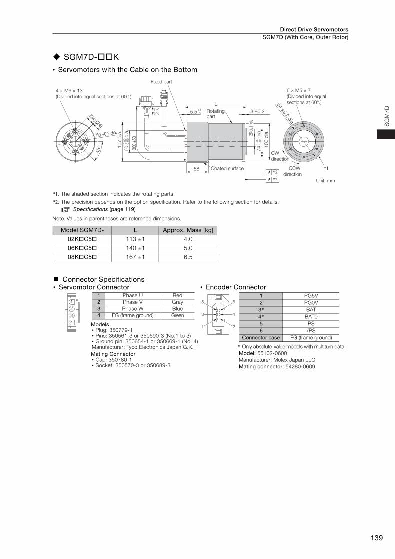
SGM7D-K
• Servomotors with the Cable on the Bottom
*1. The shaded section indicates the rotating parts.
*2. The precision depends on the option specification. Refer to the following section for details.Specifications (page 119)
Note: Values in parentheses are reference dimensions.
Model SGM7D- L Approx. Mass [kg]
02KC5 113 ±1 4.0
06KC5 140 ±1 5.0
08KC5 167 ±1 6.5
Connector Specifications• Servomotor Connector • Encoder Connector
Models• Plug: 350779-1• Pins: 350561-3 or 350690-3 (No.1 to 3)• Ground pin: 350654-1 or 350669-1 (No. 4)Manufacturer: Tyco Electronics Japan G.K.Mating Connector• Cap: 350780-1• Socket: 350570-3 or 350689-3
* Only absolute-value models with multiturn data.Model: 55102-0600Manufacturer: Molex Japan LLCMating connector: 54280-0609
*2*2
*1
(35
)
300
±50
L
3 ±0.2
45
°
(24) (24)
5.5+1
0
58
6 × M5 × 7
(Divided into equal
sections at 60°.)
4 × M6 × 13
(Divided into equal sections at 60°.)
L
CW
direction
84 ±0.2 d
ia.
CCW
direction
50 ±0.2 dia.
Fixed part
Coated surface
10
0 d
ia.
(26
dia.
) hole
74
d
ia.
-0.0
2-0
.06
10
7 d
ia.
60
d
ia.
-0.0
2-0
.06
Unit: mm
Rotating part
1
2
3
4
1 Phase U Red2 Phase V Gray3 Phase W Blue4 FG (frame ground) Green 4
2
6
3
1
5
1 PG5V2 PG0V3* BAT4* BAT05 PS6 /PS
Connector case FG (frame ground)
Direct Drive ServomotorsSGM7D (With Core, Outer Rotor)
140
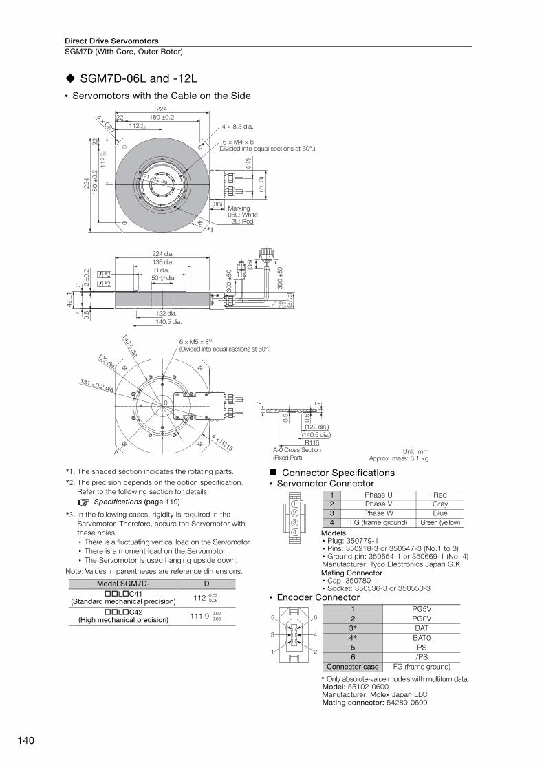
SGM7D-06L and -12L• Servomotors with the Cable on the Side
*1. The shaded section indicates the rotating parts.
*2. The precision depends on the option specification. Refer to the following section for details.
Specifications (page 119)
*3. In the following cases, rigidity is required in the Servomotor. Therefore, secure the Servomotor with these holes.• There is a fluctuating vertical load on the Servomotor.• There is a moment load on the Servomotor.• The Servomotor is used hanging upside down.
Note: Values in parentheses are reference dimensions.
Connector Specifications• Servomotor Connector
Models• Plug: 350779-1• Pins: 350218-3 or 350547-3 (No.1 to 3)• Ground pin: 350654-1 or 350669-1 (No. 4)Manufacturer: Tyco Electronics Japan G.K.Mating Connector• Cap: 350780-1• Socket: 350536-3 or 350550-3
• Encoder Connector
* Only absolute-value models with multiturn data.Model: 55102-0600Manufacturer: Molex Japan LLCMating connector: 54280-0609
37
0.5
7 7
0.5
0.5
A
42 ±
1
2 ±
0.2
0
*2*2
224 dia.
136 dia.
122 dia.
140.5 dia.
6 × M5 × 8*3
(Divided into equal sections at 60°.)
4 × R115A-0 Cross Section
(Fixed Part)
(122 dia.)
(140.5 dia.)
R115
D dia.
Unit: mmApprox. mass: 8.1 kg
131 ±0.2 dia.
122 dia.
140.5
dia.
50 dia.
300 ±
50
300 ±
50
(19)
(37.5
)
(35)
+0.50
224
180 ±0.2
18
0 ±
0.2
224 × C20
22
22
4
112 0-0.2
11
20 -0
.2
*1
(32
)
(70
.3)
(36)Marking06L: White12L: Red
4 × 8.5 dia.
6 × M4 × 6(Divided into equal sections at 60°.)
121 ±0.2 dia.
Model SGM7D- DLC41
(Standard mechanical precision) 112
LC42(High mechanical precision) 111.9
-0.02-0.06
-0.02-0.06
1
2
3
4
1 Phase U Red2 Phase V Gray3 Phase W Blue4 FG (frame ground) Green (yellow)
4
2
6
3
1
5
1 PG5V2 PG0V3* BAT4* BAT05 PS6 /PS
Connector case FG (frame ground)
Direct Drive Servomotors SGM7D (With Core, Outer Rotor)
141
SG
M7
D
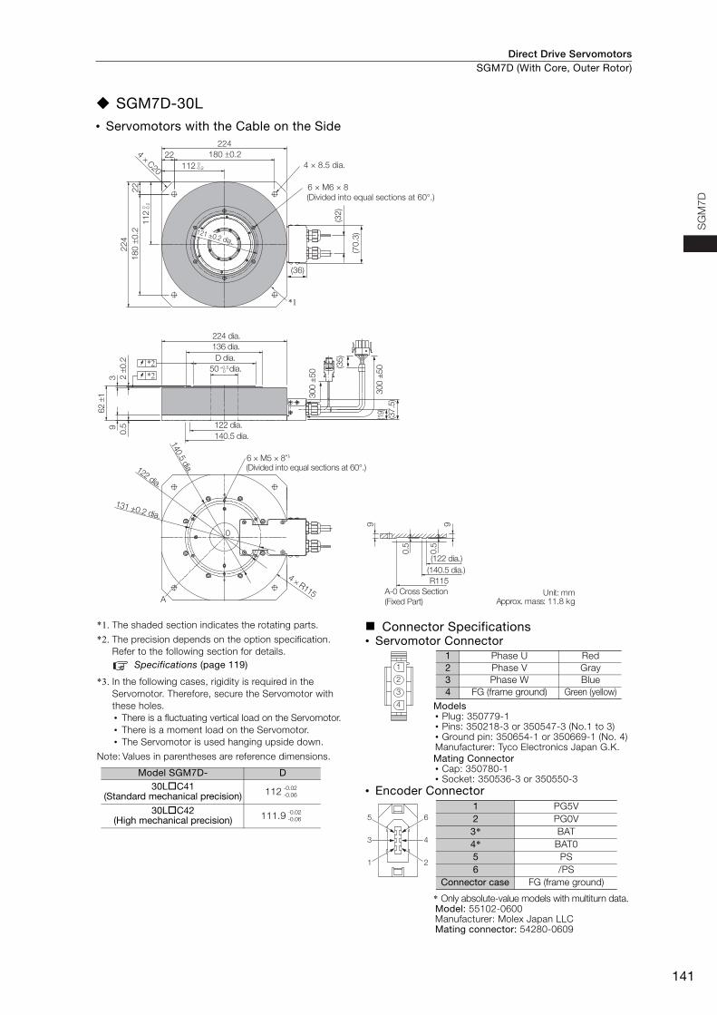
SGM7D-30L• Servomotors with the Cable on the Side
*1. The shaded section indicates the rotating parts.
*2. The precision depends on the option specification. Refer to the following section for details.
Specifications (page 119)
*3. In the following cases, rigidity is required in the Servomotor. Therefore, secure the Servomotor with these holes.• There is a fluctuating vertical load on the Servomotor.• There is a moment load on the Servomotor.• The Servomotor is used hanging upside down.
Note: Values in parentheses are reference dimensions.
Connector Specifications• Servomotor Connector
Models• Plug: 350779-1• Pins: 350218-3 or 350547-3 (No.1 to 3)• Ground pin: 350654-1 or 350669-1 (No. 4)Manufacturer: Tyco Electronics Japan G.K.Mating Connector• Cap: 350780-1• Socket: 350536-3 or 350550-3
• Encoder Connector
* Only absolute-value models with multiturn data.Model: 55102-0600Manufacturer: Molex Japan LLCMating connector: 54280-0609
224 dia.
136 dia.
D dia.
50 dia.
122 dia.
140.5 dia.
(Divided into equal sections at 60°.)
(122 dia.)
(140.5 dia.)
R115
A-0 Cross Section
(Fixed Part)
6 × M5 × 8*3
Unit: mmApprox. mass: 11.8 kg
39
0.5
62 ±
1
2 ±
0.2
4 × R115A
9 9
0.5
0.5
0
*2*2
300 ±
50
300 ±
50
(19)
(37.5
)
(35)
131 ±0.2 dia.
122 dia.
140.5
dia.
+0.50
180 ±0.2
224
224 × C20 112 0
-0.2
18
0 ±
0.2
22
22
4
11
20 -0.2
*1
(32
)
(70
.3)
(36)
4 × 8.5 dia.
6 × M6 × 8
(Divided into equal sections at 60°.)
121 ±0.2 dia.
Model SGM7D- D30LC41
(Standard mechanical precision) 112
30LC42(High mechanical precision) 111.9
-0.02-0.06
-0.02-0.06
1
2
3
4
1 Phase U Red2 Phase V Gray3 Phase W Blue4 FG (frame ground) Green (yellow)
4
2
6
3
1
5
1 PG5V2 PG0V3* BAT4* BAT05 PS6 /PS
Connector case FG (frame ground)
Direct Drive ServomotorsSGM7D (With Core, Outer Rotor)
142
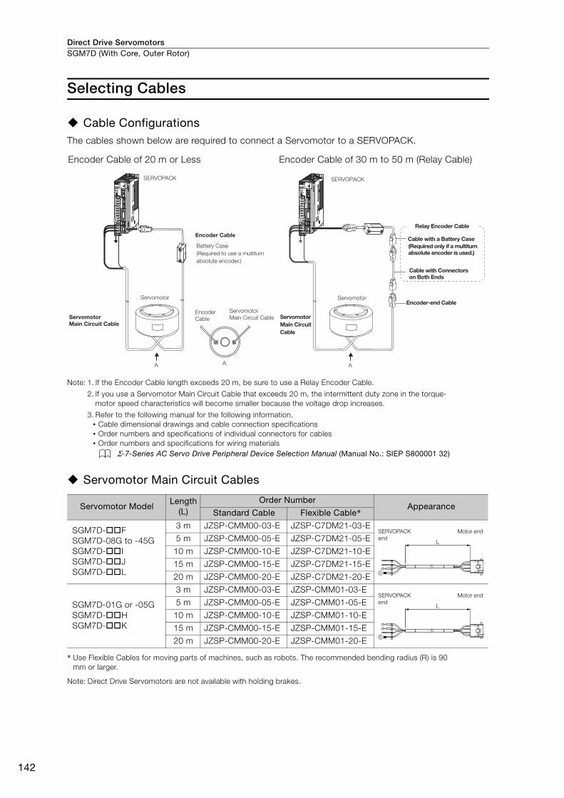
Selecting Cables
Cable ConfigurationsThe cables shown below are required to connect a Servomotor to a SERVOPACK.
Note: 1. If the Encoder Cable length exceeds 20 m, be sure to use a Relay Encoder Cable.
2. If you use a Servomotor Main Circuit Cable that exceeds 20 m, the intermittent duty zone in the torque-motor speed characteristics will become smaller because the voltage drop increases.
3. Refer to the following manual for the following information.• Cable dimensional drawings and cable connection specifications• Order numbers and specifications of individual connectors for cables• Order numbers and specifications for wiring materials
Σ-7-Series AC Servo Drive Peripheral Device Selection Manual (Manual No.: SIEP S800001 32)
Servomotor Main Circuit Cables
* Use Flexible Cables for moving parts of machines, such as robots. The recommended bending radius (R) is 90 mm or larger.
Note: Direct Drive Servomotors are not available with holding brakes.
Encoder Cable of 20 m or Less Encoder Cable of 30 m to 50 m (Relay Cable)
Servomotor ModelLength
(L)Order Number
AppearanceStandard Cable Flexible Cable*
SGM7D-FSGM7D-08G to -45GSGM7D-ISGM7D-JSGM7D-L
3 m JZSP-CMM00-03-E JZSP-C7DM21-03-E
5 m JZSP-CMM00-05-E JZSP-C7DM21-05-E
10 m JZSP-CMM00-10-E JZSP-C7DM21-10-E
15 m JZSP-CMM00-15-E JZSP-C7DM21-15-E
20 m JZSP-CMM00-20-E JZSP-C7DM21-20-E
SGM7D-01G or -05GSGM7D-HSGM7D-K
3 m JZSP-CMM00-03-E JZSP-CMM01-03-E
5 m JZSP-CMM00-05-E JZSP-CMM01-05-E
10 m JZSP-CMM00-10-E JZSP-CMM01-10-E
15 m JZSP-CMM00-15-E JZSP-CMM01-15-E
20 m JZSP-CMM00-20-E JZSP-CMM01-20-E
SERVOPACK
Encoder Cable
Encoder
Cable
Servomotor
Servomotor Main Circuit Cable
Servomotor
Main Circuit Cable
A A
Battery Case
(Required to use a multiturn
absolute encoder.)
SERVOPACK
Cable with a Battery Case(Required only if a multiturn absolute encoder is used.)
Cable with Connectors on Both Ends
Encoder-end CableServomotor
Servomotor Main Circuit Cable
A
Relay Encoder Cable
L
SERVOPACK
end
Motor end
L
SERVOPACK
end
Motor end
Direct Drive Servomotors SGM7D (With Core, Outer Rotor)
143
SG
M7D
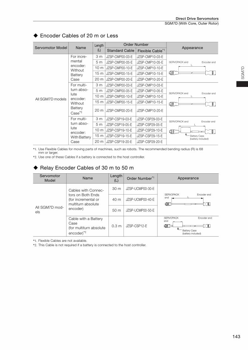
Encoder Cables of 20 m or Less
*1. Use Flexible Cables for moving parts of machines, such as robots. The recommended bending radius (R) is 68 mm or larger.
*2. Use one of these Cables if a battery is connected to the host controller.
Relay Encoder Cables of 30 m to 50 m
*1. Flexible Cables are not available.*2. This Cable is not required if a battery is connected to the host controller.
Servomotor Model NameLength
(L)
Order NumberAppearance
Standard Cable Flexible Cable*1
All SGM7D models
For incre-mental encoder: Without Battery Case
3 m JZSP-CMP00-03-E JZSP-CMP10-03-E5 m JZSP-CMP00-05-E JZSP-CMP10-05-E
10 m JZSP-CMP00-10-E JZSP-CMP10-10-E15 m JZSP-CMP00-15-E JZSP-CMP10-15-E
20 m JZSP-CMP00-20-E JZSP-CMP10-20-E
For multi-turn abso-lute encoder: Without Battery Case*2
3 m JZSP-CMP00-03-E JZSP-CMP10-03-E5 m JZSP-CMP00-05-E JZSP-CMP10-05-E
10 m JZSP-CMP00-10-E JZSP-CMP10-10-E15 m JZSP-CMP00-15-E JZSP-CMP10-15-E
20 m JZSP-CMP00-20-E JZSP-CMP10-20-E
For multi-turn abso-lute encoder: With Battery Case
3 m JZSP-CSP19-03-E JZSP-CSP29-03-E5 m JZSP-CSP19-05-E JZSP-CSP29-05-E
10 m JZSP-CSP19-10-E JZSP-CSP29-10-E15 m JZSP-CSP19-15-E JZSP-CSP29-15-E
20 m JZSP-CSP19-20-E JZSP-CSP29-20-E
Servomotor Model
NameLength
(L) Order Number*1 Appearance
All SGM7D mod-els
Cables with Connec-tors on Both Ends (for incremental or multiturn absolute encoder)
30 m JZSP-UCMP00-30-E
40 m JZSP-UCMP00-40-E
50 m JZSP-UCMP00-50-E
Cable with a Battery Case (for multiturn absolute encoder)*2
0.3 m JZSP-CSP12-E
LSERVOPACK end Encoder end
LSERVOPACK end Encoder end
Encoder endSERVOPACK endL
Battery Case (battery included)
LSERVOPACK end
Encoder end
SERVOPACK end
Encoder end
Battery Case (battery included)
Direct Drive Servomotors
144
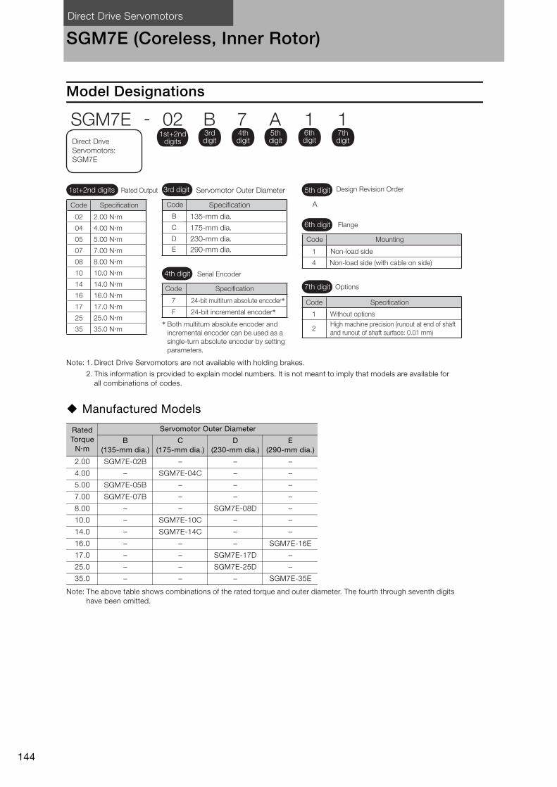
SGM7E (Coreless, Inner Rotor)
Model Designations
Note: 1. Direct Drive Servomotors are not available with holding brakes.
2. This information is provided to explain model numbers. It is not meant to imply that models are available for all combinations of codes.
Manufactured Models
Note: The above table shows combinations of the rated torque and outer diameter. The fourth through seventh digits have been omitted.
Rated Torque
Nm
Servomotor Outer Diameter
B (135-mm dia.)
C (175-mm dia.)
D (230-mm dia.)
E (290-mm dia.)
2.00 SGM7E-02B – – –
4.00 – SGM7E-04C – –
5.00 SGM7E-05B – – –
7.00 SGM7E-07B – – –
8.00 – – SGM7E-08D –
10.0 – SGM7E-10C – –
14.0 – SGM7E-14C – –
16.0 – – – SGM7E-16E
17.0 – – SGM7E-17D –
25.0 – – SGM7E-25D –
35.0 – – – SGM7E-35E
4th digit
6th digit
7th digit
Mounting
Non-load side
Non-load side (with cable on side)
Options
Without optionsHigh machine precision (runout at end of shaft and runout of shaft surface: 0.01 mm)
24-bit multiturn absolute encoder*24-bit incremental encoder*
A
5th digit Design Revision Order
Serial Encoder
Flange
SGM7E - 02 B 7 A 1 11st+2nd
digits
1st+2nd digits Rated Output
3rd digit
4th digit
5th digit
6th digit
7th digitDirect Drive
Servomotors: SGM7E
Code
Code
Code
Specification
Specification7
F 1
2
1
4
B
C
D
E
3rd digit
135-mm dia.
Specification
175-mm dia.
230-mm dia.290-mm dia.
Servomotor Outer Diameter
CodeSpecificationCode
02 2.00 Nm
04 4.00 Nm
05 5.00 Nm
07 7.00 Nm
08 8.00 Nm
10 10.0 Nm
14 14.0 Nm
16 16.0 Nm
17 17.0 Nm
25 25.0 Nm
35 35.0 Nm* Both multiturn absolute encoder and
incremental encoder can be used as a single-turn absolute encoder by setting parameters.
Direct Drive Servomotors SGM7E (Coreless, Inner Rotor)
145
SG
M7E
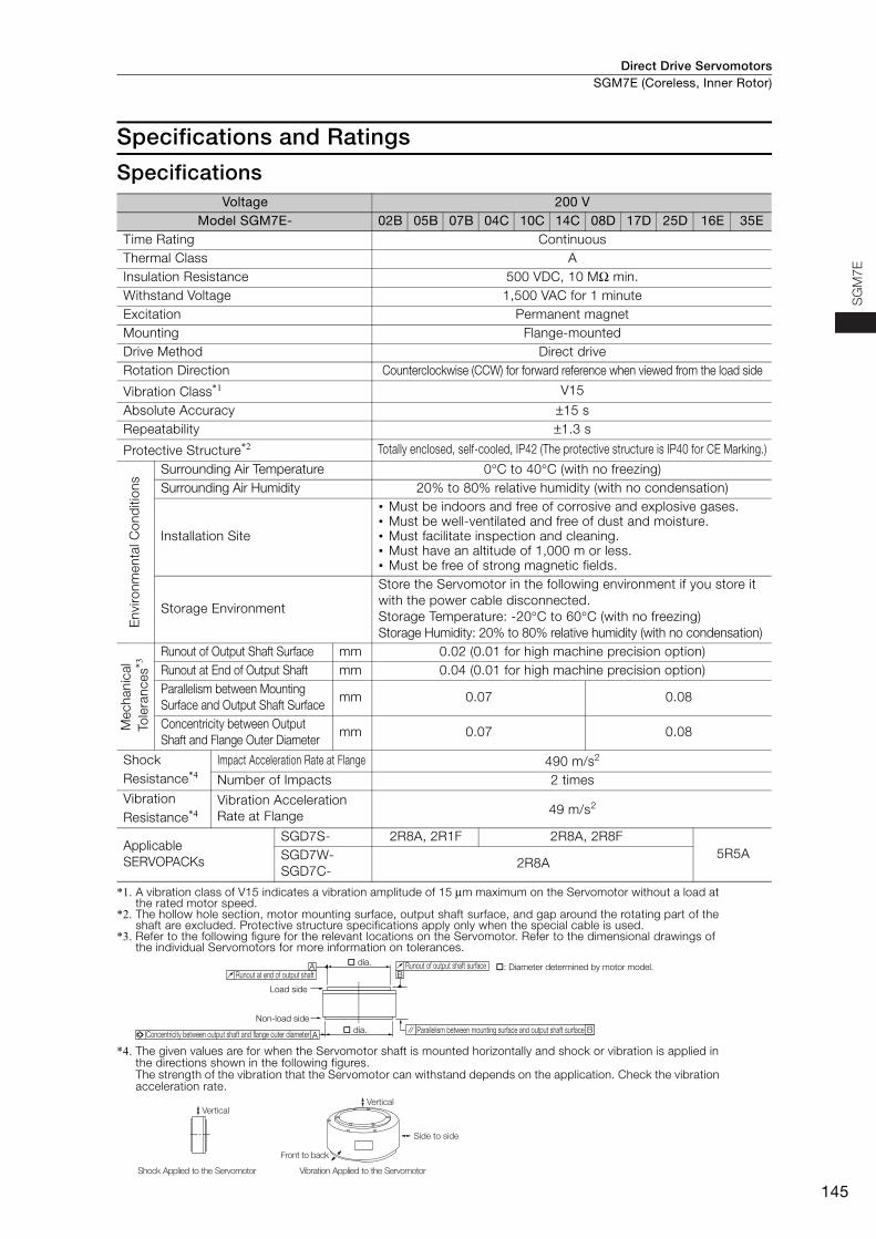
Specifications and Ratings
Specifications
*1. A vibration class of V15 indicates a vibration amplitude of 15 μm maximum on the Servomotor without a load at the rated motor speed.
*2. The hollow hole section, motor mounting surface, output shaft surface, and gap around the rotating part of the shaft are excluded. Protective structure specifications apply only when the special cable is used.
*3. Refer to the following figure for the relevant locations on the Servomotor. Refer to the dimensional drawings of the individual Servomotors for more information on tolerances.
*4. The given values are for when the Servomotor shaft is mounted horizontally and shock or vibration is applied in the directions shown in the following figures.The strength of the vibration that the Servomotor can withstand depends on the application. Check the vibration acceleration rate.
Voltage 200 VModel SGM7E- 02B 05B 07B 04C 10C 14C 08D 17D 25D 16E 35E
Time Rating Continuous Thermal Class AInsulation Resistance 500 VDC, 10 MΩ min. Withstand Voltage 1,500 VAC for 1 minute Excitation Permanent magnet Mounting Flange-mounted Drive Method Direct drive Rotation Direction Counterclockwise (CCW) for forward reference when viewed from the load side
Vibration Class*1 V15
Absolute Accuracy ±15 s Repeatability ±1.3 s
Protective Structure*2 Totally enclosed, self-cooled, IP42 (The protective structure is IP40 for CE Marking.)
Env
ironm
enta
l Con
diti
ons
Surrounding Air Temperature 0°C to 40°C (with no freezing) Surrounding Air Humidity 20% to 80% relative humidity (with no condensation)
Installation Site
• Must be indoors and free of corrosive and explosive gases. • Must be well-ventilated and free of dust and moisture. • Must facilitate inspection and cleaning. • Must have an altitude of 1,000 m or less.• Must be free of strong magnetic fields.
Storage Environment
Store the Servomotor in the following environment if you store it with the power cable disconnected.Storage Temperature: -20°C to 60°C (with no freezing) Storage Humidity: 20% to 80% relative humidity (with no condensation)
Mec
hani
cal
Tol
eran
ces*3
Runout of Output Shaft Surface mm 0.02 (0.01 for high machine precision option)Runout at End of Output Shaft mm 0.04 (0.01 for high machine precision option)Parallelism between Mounting Surface and Output Shaft Surface
mm 0.07 0.08
Concentricity between Output Shaft and Flange Outer Diameter
mm 0.07 0.08
Shock Resistance*4
Impact Acceleration Rate at Flange 490 m/s2
Number of Impacts 2 times Vibration Resistance*4
Vibration Acceleration Rate at Flange 49 m/s2
Applicable SERVOPACKs
SGD7S- 2R8A, 2R1F 2R8A, 2R8F5R5ASGD7W-
SGD7C-2R8A
A
AB
B
dia.
dia.
Runout of output shaft surface
Parallelism between mounting surface and output shaft surface
Runout at end of output shaft
Load side
Non-load side
Concentricity between output shaft and flange outer diameter
: Diameter determined by motor model.
Side to side
Front to back
Vertical
Shock Applied to the Servomotor Vibration Applied to the Servomotor
Vertical
Direct Drive ServomotorsSGM7E (Coreless, Inner Rotor)
146
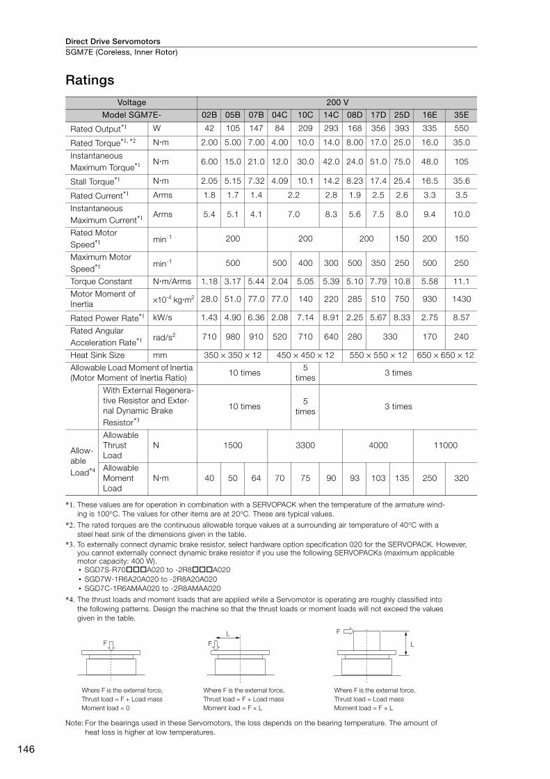
Ratings
*1. These values are for operation in combination with a SERVOPACK when the temperature of the armature wind-ing is 100°C. The values for other items are at 20°C. These are typical values.
*2. The rated torques are the continuous allowable torque values at a surrounding air temperature of 40°C with a steel heat sink of the dimensions given in the table.
*3. To externally connect dynamic brake resistor, select hardware option specification 020 for the SERVOPACK. However, you cannot externally connect dynamic brake resistor if you use the following SERVOPACKs (maximum applicable motor capacity: 400 W).• SGD7S-R70A020 to -2R8A020• SGD7W-1R6A20A020 to -2R8A20A020• SGD7C-1R6AMAA020 to -2R8AMAA020
*4. The thrust loads and moment loads that are applied while a Servomotor is operating are roughly classified into the following patterns. Design the machine so that the thrust loads or moment loads will not exceed the values given in the table.
Note: For the bearings used in these Servomotors, the loss depends on the bearing temperature. The amount of heat loss is higher at low temperatures.
Voltage 200 V
Model SGM7E- 02B 05B 07B 04C 10C 14C 08D 17D 25D 16E 35E
Rated Output*1 W 42 105 147 84 209 293 168 356 393 335 550
Rated Torque*1, *2 Nm 2.00 5.00 7.00 4.00 10.0 14.0 8.00 17.0 25.0 16.0 35.0
Instantaneous Maximum Torque*1 Nm 6.00 15.0 21.0 12.0 30.0 42.0 24.0 51.0 75.0 48.0 105
Stall Torque*1 Nm 2.05 5.15 7.32 4.09 10.1 14.2 8.23 17.4 25.4 16.5 35.6
Rated Current*1 Arms 1.8 1.7 1.4 2.2 2.8 1.9 2.5 2.6 3.3 3.5
Instantaneous Maximum Current*1 Arms 5.4 5.1 4.1 7.0 8.3 5.6 7.5 8.0 9.4 10.0
Rated Motor Speed*1 min-1 200 200 200 150 200 150
Maximum Motor Speed*1 min-1 500 500 400 300 500 350 250 500 250
Torque Constant Nm/Arms 1.18 3.17 5.44 2.04 5.05 5.39 5.10 7.79 10.8 5.58 11.1
Motor Moment of Inertia ×10-4 kgm2 28.0 51.0 77.0 77.0 140 220 285 510 750 930 1430
Rated Power Rate*1 kW/s 1.43 4.90 6.36 2.08 7.14 8.91 2.25 5.67 8.33 2.75 8.57
Rated Angular Acceleration Rate*1 rad/s2 710 980 910 520 710 640 280 330 170 240
Heat Sink Size mm 350 × 350 × 12 450 × 450 × 12 550 × 550 × 12 650 × 650 × 12
Allowable Load Moment of Inertia (Motor Moment of Inertia Ratio)
10 times5
times3 times
With External Regenera-tive Resistor and Exter-nal Dynamic Brake Resistor*3
10 times5
times3 times
Allow-able Load*4
Allowable Thrust Load
N 1500 3300 4000 11000
Allowable Moment Load
Nm 40 50 64 70 75 90 93 103 135 250 320
F
F
LF
L
Where F is the external force,Thrust load = F + Load massMoment load = 0
Where F is the external force,Thrust load = Load massMoment load = F × L
Where F is the external force,Thrust load = F + Load massMoment load = F × L
Direct Drive Servomotors SGM7E (Coreless, Inner Rotor)
147
SG
M7E
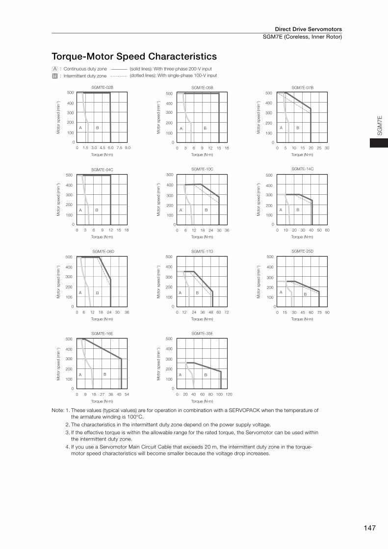
Torque-Motor Speed Characteristics
Note: 1. These values (typical values) are for operation in combination with a SERVOPACK when the temperature of the armature winding is 100°C.
2. The characteristics in the intermittent duty zone depend on the power supply voltage.
3. If the effective torque is within the allowable range for the rated torque, the Servomotor can be used within the intermittent duty zone.
4. If you use a Servomotor Main Circuit Cable that exceeds 20 m, the intermittent duty zone in the torque-motor speed characteristics will become smaller because the voltage drop increases.
SGM7E-02B
A
00
100
1.5 3.0 4.5 6.0 7.5 9.0
200
300
400
500
B
SGM7E-05B
A
00
100
3 6 9 12 15 18
200
300
400
500
B
SGM7E-07B
A
00
100
5 10 15 20 25 30
200
300
400
500
B
SGM7E-04C
A
00
100
3 6 9 12 15 18
200
300
400
500
B
SGM7E-10C
A
0
0
100
6 12 18 24 30 36
200
300
400
500
B
SGM7E-14C
A
00
100
10 20 30 40 50 60
200
300
400
500
B
100
200
300
400
500SGM7E-08D
0
0
100
6 12 18 24 30 36
200
300
400
500SGM7E-17D
A
0
0
12 24 36 48 60 72
B
100
200
300
400
500SGM7E-16E
A
0
0
100
9 18 27 36 45 54
200
300
400
500
B
SGM7E-35E
A
0
0
20 40 60 80 100 120
B
SGM7E-25D
A
0
0
100
15 30 45 60 75 90
200
300
400
500
BA B
A :
B :Continuous duty zone (solid lines): With three-phase 200-V input
(dotted lines): With single-phase 100-V inputIntermittent duty zone
Torque (N�m)
Mot
or s
peed
(min
-1)
Torque (N�m)M
otor
spe
ed (m
in-1)
Torque (N�m)
Mot
or s
peed
(min
-1)
Torque (N�m)
Mot
or s
peed
(min
-1)
Torque (N�m)
Mot
or s
peed
(min
-1)
Torque (N�m)
Mot
or s
peed
(min
-1)
Torque (N�m)
Mot
or s
peed
(min
-1)
Torque (N�m)
Mot
or s
peed
(min
-1)
Torque (N�m)
Mot
or s
peed
(min
-1)
Torque (N�m)
Mot
or s
peed
(min
-1)
Torque (N�m)
Mot
or s
peed
(min
-1)
Direct Drive ServomotorsSGM7E (Coreless, Inner Rotor)
148
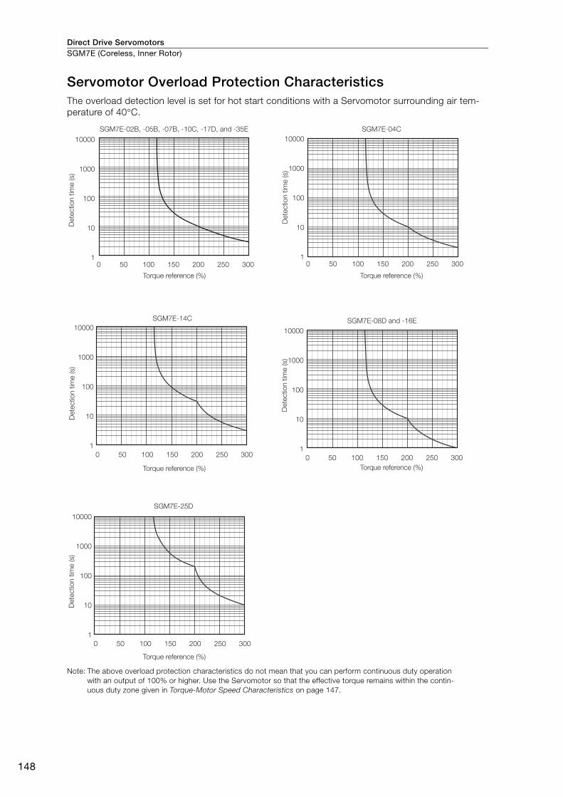
Servomotor Overload Protection CharacteristicsThe overload detection level is set for hot start conditions with a Servomotor surrounding air tem-perature of 40°C.
Note: The above overload protection characteristics do not mean that you can perform continuous duty operation with an output of 100% or higher. Use the Servomotor so that the effective torque remains within the contin-uous duty zone given in Torque-Motor Speed Characteristics on page 147.
SGM7E-02B, -05B, -07B, -10C, -17D, and -35E SGM7E-04C
SGM7E-14C
SGM7E-25D
SGM7E-08D and -16E
Det
ectio
n tim
e (s
)
Torque reference (%)D
etec
tion
time
(s)
Det
ectio
n tim
e (s
)
Det
ectio
n tim
e (s
)D
etec
tion
time
(s)
Torque reference (%)
Torque reference (%) Torque reference (%)
Torque reference (%)
0 50 100 150 200 250 300
10000
1000
100
10
10 50 100 150 200 250 300
10000
1000
100
10
1
0 50 100 150 200 250 300
10000
1000
100
10
1
0 50 100 150 200 250 300
10000
1000
100
10
1
0 50 100 150 200 250 300
10000
1000
100
10
1
Direct Drive Servomotors SGM7E (Coreless, Inner Rotor)
149
SG
M7E
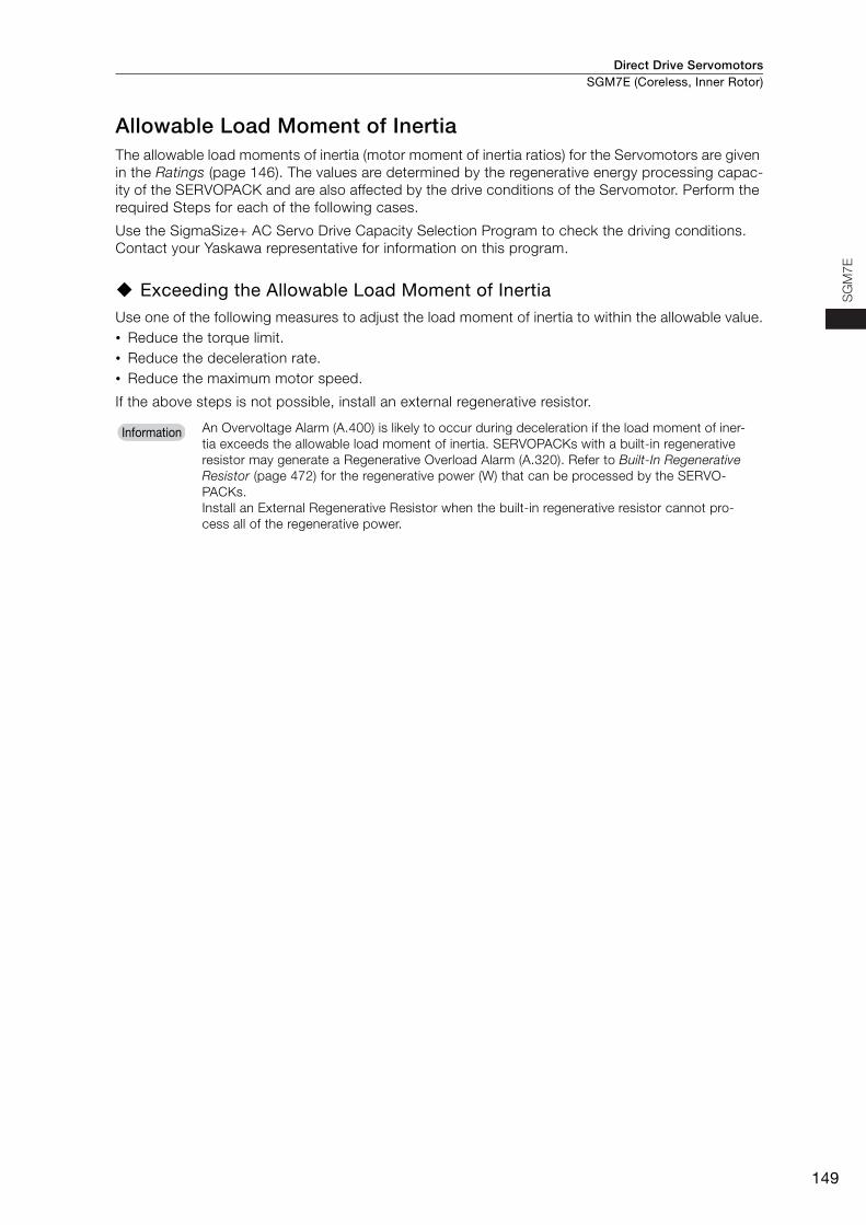
Allowable Load Moment of InertiaThe allowable load moments of inertia (motor moment of inertia ratios) for the Servomotors are given in the Ratings (page 146). The values are determined by the regenerative energy processing capac-ity of the SERVOPACK and are also affected by the drive conditions of the Servomotor. Perform the required Steps for each of the following cases.
Use the SigmaSize+ AC Servo Drive Capacity Selection Program to check the driving conditions. Contact your Yaskawa representative for information on this program.
Exceeding the Allowable Load Moment of InertiaUse one of the following measures to adjust the load moment of inertia to within the allowable value.• Reduce the torque limit.• Reduce the deceleration rate.• Reduce the maximum motor speed.
If the above steps is not possible, install an external regenerative resistor.
An Overvoltage Alarm (A.400) is likely to occur during deceleration if the load moment of iner-tia exceeds the allowable load moment of inertia. SERVOPACKs with a built-in regenerative resistor may generate a Regenerative Overload Alarm (A.320). Refer to Built-In Regenerative Resistor (page 472) for the regenerative power (W) that can be processed by the SERVO-PACKs.Install an External Regenerative Resistor when the built-in regenerative resistor cannot pro-cess all of the regenerative power.
Information
Direct Drive ServomotorsSGM7E (Coreless, Inner Rotor)
150
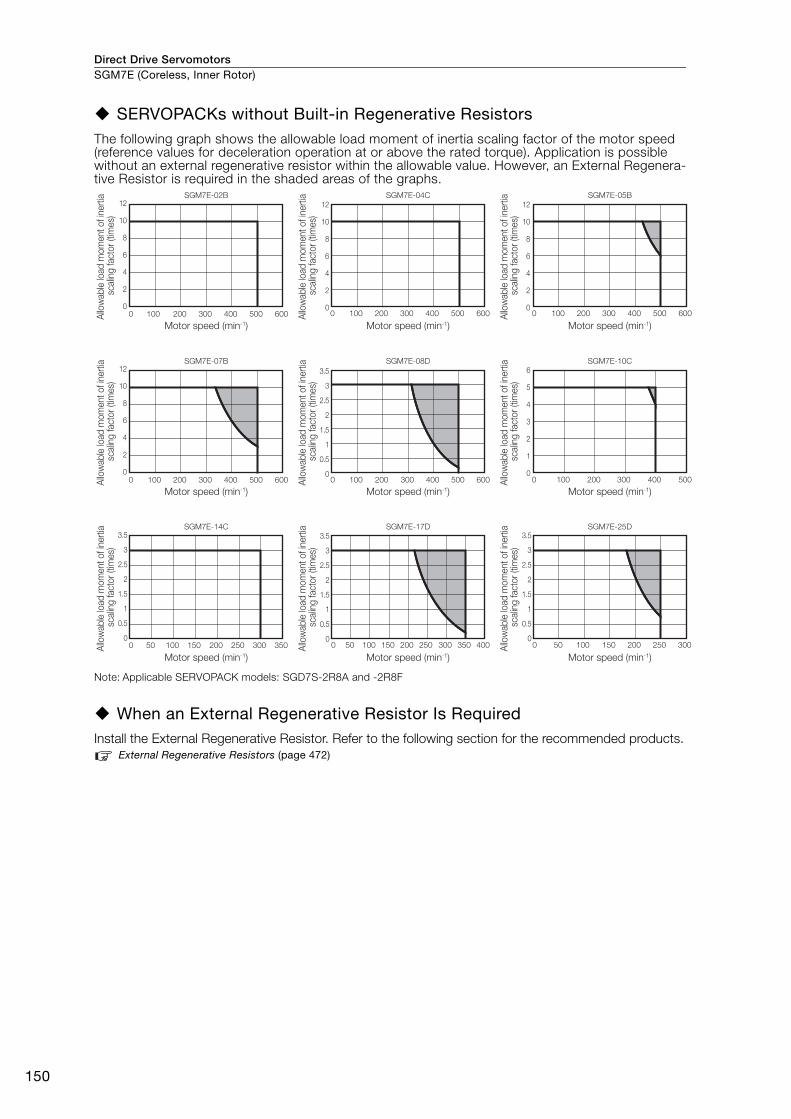
SERVOPACKs without Built-in Regenerative ResistorsThe following graph shows the allowable load moment of inertia scaling factor of the motor speed (reference values for deceleration operation at or above the rated torque). Application is possible without an external regenerative resistor within the allowable value. However, an External Regenera-tive Resistor is required in the shaded areas of the graphs.
Note: Applicable SERVOPACK models: SGD7S-2R8A and -2R8F
When an External Regenerative Resistor Is RequiredInstall the External Regenerative Resistor. Refer to the following section for the recommended products.
External Regenerative Resistors (page 472)
0
2
4
6
8
10
12
0 100 200 300 400 500 600
SGM7E-02B
0
2
4
6
8
10
12
0 100 200 300 400 500 600
SGM7E-04C
0
2
4
6
8
10
12
0 100 200 300 400 500 600
SGM7E-07B
0
0.5
1
1.5
2
2.5
3
3.5
0 100 200 300 400 500 600
SGM7E-08D
0
1
2
3
4
5
6
0 100 200 300 400 500
SGM7E-10C
0
0.5
1
1.5
2
2.5
3
3.5
0 50 100 150 200 250 300 350
SGM7E-14C
0
0.5
1
1.5
2
2.5
3
3.5
0 50 100 150 200 250 300 350 400
SGM7E-17D
0
0.5
1
1.5
2
2.5
3
3.5
0 50 100 150 200 250 300
SGM7E-25D
0
2
4
6
8
10
12
0 100 200 300 400 500 600
SGM7E-05B
Motor speed (min-1)
Allo
wab
le lo
ad m
omen
t of i
nerti
a sc
alin
g fa
ctor
(tim
es)
Motor speed (min-1)
Allo
wab
le lo
ad m
omen
t of i
nerti
a sc
alin
g fa
ctor
(tim
es)
Motor speed (min-1)
Allo
wab
le lo
ad m
omen
t of i
nerti
a sc
alin
g fa
ctor
(tim
es)
Motor speed (min-1)
Allo
wab
le lo
ad m
omen
t of i
nerti
a sc
alin
g fa
ctor
(tim
es)
Motor speed (min-1)
Allo
wab
le lo
ad m
omen
t of i
nerti
a sc
alin
g fa
ctor
(tim
es)
Motor speed (min-1)Al
low
able
load
mom
ent o
f ine
rtia
scal
ing
fact
or (t
imes
)
Motor speed (min-1)
Allo
wab
le lo
ad m
omen
t of i
nerti
a sc
alin
g fa
ctor
(tim
es)
Motor speed (min-1)
Allo
wab
le lo
ad m
omen
t of i
nerti
a sc
alin
g fa
ctor
(tim
es)
Motor speed (min-1)
Allo
wab
le lo
ad m
omen
t of i
nerti
a sc
alin
g fa
ctor
(tim
es)
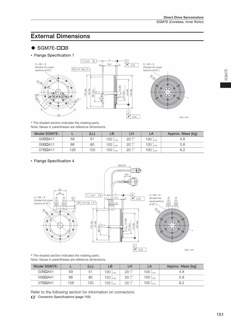
Direct Drive Servomotors SGM7E (Coreless, Inner Rotor)
151
SG
M7E
External Dimensions
SGM7E-B• Flange Specification 1
* The shaded section indicates the rotating parts. Note: Values in parentheses are reference dimensions.
• Flange Specification 4
* The shaded section indicates the rotating parts. Note: Values in parentheses are reference dimensions.
Refer to the following section for information on connectors. Connector Specifications (page 155)
Model SGM7E- L (LL) LB LH LA Approx. Mass [kg]
02BA11 59 51 120 20 100 4.8
05BA11 88 80 120 20 100 5.8
07BA11 128 120 120 20 100 8.2
Model SGM7E- L (LL) LB LH LA Approx. Mass [kg]
02BA41 59 51 120 20 100 4.8
05BA41 88 80 120 20 100 5.8
07BA41 128 120 120 20 100 8.2
(LL)
L
6 × M4 × 8(Divided into equal sections at 60°.)
6 × M4 × 8(Divided into equal sections at 60°.)
�25.4
�23.4
A0.07 dia.
0.07 B
LB d
ia.
LH d
ia.
LA d
ia.
B
0.02
0.04
A
90 dia.
4
135
dia.
(80
dia.
)(0.1)
(70
dia.
)
134
dia.
90°
R26
90 dia.
4
*
Unit: mm
(1)
0-0.035
+0.4 0
0-0.035
0-0.035
+0.4 0
0-0.035
0-0.035
+0.4 0
0-0.035
300±50
(35)
10(2
2)
90 dia.
4
20
30
50
135
dia.
(80
dia.
)
(70
dia.
)
LA d
ia.
134
dia.
(LL)
L
(1)
4
A0.07 dia.
0.07 B
LB d
ia.
LH d
ia.
B
0.02
0.04
A
90 dia.
*
(0.1)
Unit: mm
6 × M4 × 8(Divided into equal sections at 60°.)
6 × M4 × 8(Divided into equal sections at 60°.)
0-0.035
+0.4 0
0-0.035
0-0.035
+0.4 0
0-0.035
0-0.035
+0.4 0
0-0.035
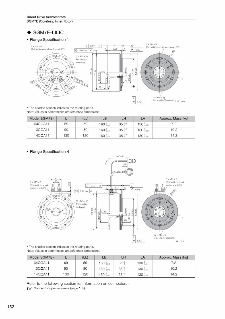
Direct Drive ServomotorsSGM7E (Coreless, Inner Rotor)
152
SGM7E-C• Flange Specification 1
* The shaded section indicates the rotating parts. Note: Values in parentheses are reference dimensions.
• Flange Specification 4
* The shaded section indicates the rotating parts. Note: Values in parentheses are reference dimensions.
Refer to the following section for information on connectors. Connector Specifications (page 155)
Model SGM7E- L (LL) LB LH LA Approx. Mass [kg]
04CA11 69 59 160 35 130 7.2
10CA11 90 80 160 35 130 10.2
14CA11 130 120 160 35 130 14.2
Model SGM7E- L (LL) LB LH LA Approx. Mass [kg]
04CA41 69 59 160 35 130 7.2
10CA41 90 80 160 35 130 10.2
14CA41 130 120 160 35 130 14.2
(2 × M5 × 8)(For use by Yaskawa)
6 × M5 × 8(Divided into equal sections at 60°.)6 × M5 × 8
(Divided into equal sections at 60°.)
(1) 100
dia. 17
3 di
a.
L
5
�23.4�25.4
60°
R51 max. connector areaR36.5
LA d
ia.
(0.1)
175
dia.
LB d
ia.
(9.1)
120
dia.
(LL)
(102
dia
.)
5A0.07 dia.
0.07 B
LH d
ia.
B
0.02
0.04
A
*
(2 × M5 × 8)(For use by Yaskawa)
130 dia.
Unit: mm
0-0.040
+0.4 0
0-0.040
0-0.040
+0.4 0
0-0.040
0-0.040
+0.4 0
0-0.040
(2 × M5 × 8)(For use by Yaskawa)
(2 × M5 × 8)(For use by Yaskawa)
6 × M5 × 8(Divided into equal sections at 60°.)
(1) 100
dia.
173
dia.
L
(0.1)
175
dia.
120
dia.
130 dia130 dia130 dia.
520
(LL)
300±50
(35)
3050
10(2
2)
5
(102
dia
.)
LA d
ia.
A0.07 dia.
0.07 B
LB d
ia.
LH d
ia.
B
0.02
0.04
A
*
Unit: mm
6 × M5 × 8(Divided into equal sections at 60°.)
0-0.040
+0.4 0
0-0.040
0-0.040
+0.4 0
0-0.040
0-0.040
+0.4 0
0-0.040
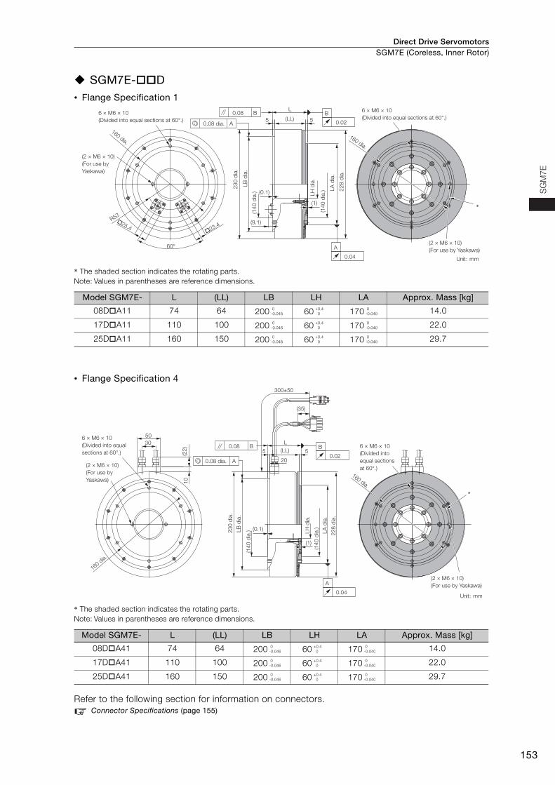
Direct Drive Servomotors SGM7E (Coreless, Inner Rotor)
153
SG
M7E
SGM7E-D• Flange Specification 1
* The shaded section indicates the rotating parts. Note: Values in parentheses are reference dimensions.
• Flange Specification 4
* The shaded section indicates the rotating parts. Note: Values in parentheses are reference dimensions.
Refer to the following section for information on connectors. Connector Specifications (page 155)
Model SGM7E- L (LL) LB LH LA Approx. Mass [kg]
08DA11 74 64 200 60 170 14.0
17DA11 110 100 200 60 170 22.0
25DA11 160 150 200 60 170 29.7
Model SGM7E- L (LL) LB LH LA Approx. Mass [kg]
08DA41 74 64 200 60 170 14.0
17DA41 110 100 200 60 170 22.0
25DA41 160 150 200 60 170 29.7
6 × M6 × 10(Divided into equal sections at 60°.)
(2 × M6 × 10)(For use by Yaskawa)
6 × M6 × 10(Divided into equal sections at 60°.)
160 dia.
230
dia.
(0.1)
(1)
228
dia.
60°
R53
160 dia.
�23.4�25.4
(140
dia
.)
(140
dia
.)
5
(9.1)
5
L
LA d
ia.
LB d
ia.
(LL)
(2 × M6 × 10) (For use by Yaskawa)
A0.08 dia.
0.08 B
LH d
ia.
B
0.02
0.04
A
*
Unit: mm
0-0.046
+0.4 0
0-0.040
0-0.046
+0.4 0
0-0.040
0-0.046
+0.4 0
0-0.040
6 × M6 × 10(Divided into equal sections at 60°.)
(2 × M6 × 10)(For use by Yaskawa)
6 × M6 × 10(Divided into equal sections at 60°.)
(2 × M6 × 10) (For use by Yaskawa)
(140
dia
.)
228
dia.
230
dia.
(140
dia
.)
5
10
3050
(22)
(0.1)
(1)
(35)
160 dia.
5
300±50
20
LA d
ia.
(LL)L
A0.08 dia.
0.08 B
LB d
ia.
LH d
ia.
B
0.02
0.04
A
160 dia.*
Unit: mm
0-0.046
+0.4 0
0-0.040
0-0.046
+0.4 0
0-0.040
0-0.046
+0.4 0
0-0.040
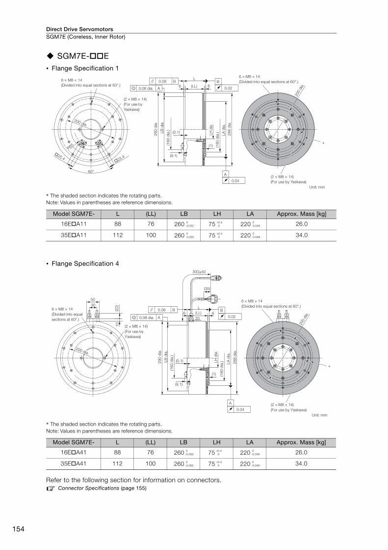
Direct Drive ServomotorsSGM7E (Coreless, Inner Rotor)
154
SGM7E-E• Flange Specification 1
* The shaded section indicates the rotating parts. Note: Values in parentheses are reference dimensions.
• Flange Specification 4
* The shaded section indicates the rotating parts. Note: Values in parentheses are reference dimensions.
Refer to the following section for information on connectors. Connector Specifications (page 155)
Model SGM7E- L (LL) LB LH LA Approx. Mass [kg]
16EA11 88 76 260 75 220 26.0
35EA11 112 100 260 75 220 34.0
Model SGM7E- L (LL) LB LH LA Approx. Mass [kg]
16EA41 88 76 260 75 220 26.0
35EA41 112 100 260 75 220 34.0
6 × M8 × 14(Divided into equal sections at 60°.)
(2 × M8 × 14)(For use by Yaskawa)
6 × M8 × 14(Divided into equal sections at 60°.) 6 6
(0.1)
(9.1)
(160
dia
.)
290
dia.
(180
dia
.) 288
dia.
200
dia.
�23.4�25.4
60°
(1)R65
LA d
ia.
(LL)
L
LB d
ia.
LH d
ia.
B
0.02
0.04
A
(2 × M8 × 14)(For use by Yaskawa)
A0.08 dia.
0.08 B
*
200 dia.
Unit: mm
0-0.052
+0.4 0
0-0.046
0-0.052
+0.4 0
0-0.046
L
(0.1)LB d
ia.
(9.1)
(160
dia
.)
290
dia.
(180
dia
.) 288
dia.
(1)
300±50
(35)
3050
10(2
2)
6 (LL) 620
200
dia.
LA d
ia.
6 × M8 × 14 (Divided into equal sections at 60°.)
6 × M8 × 14 (Divided into equal sections at 60°.)
LH d
ia.
B
0.02
0.04
A
(2 × M8 × 14) (For use by Yaskawa)
(2 × M8 × 14) (For use by Yaskawa)
A0.08 dia.
0.08 B
*
Unit: mm
200 dia.
0-0.052
+0.4 0
0-0.046
0-0.052
+0.4 0
0-0.046
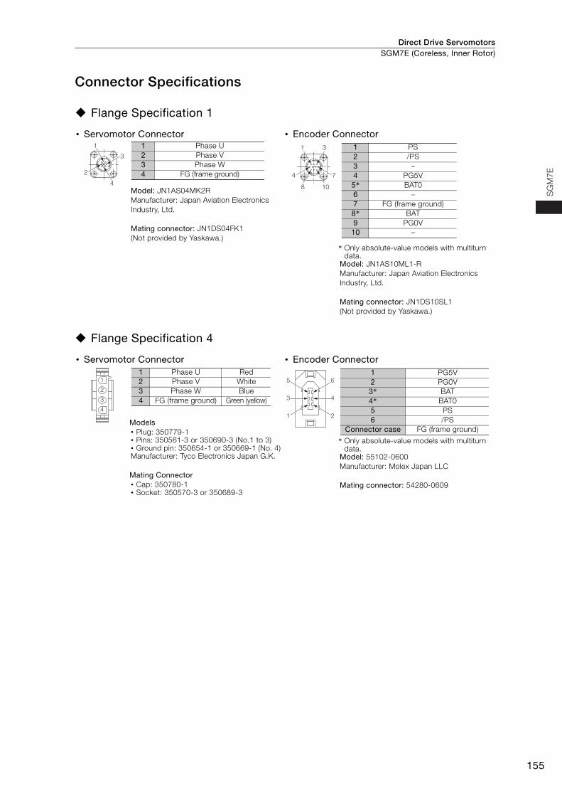
Direct Drive Servomotors SGM7E (Coreless, Inner Rotor)
155
SG
M7E
Connector Specifications
Flange Specification 1
Flange Specification 4
• Servomotor Connector • Encoder Connector
Model: JN1AS04MK2RManufacturer: Japan Aviation Electronics Industry, Ltd.
Mating connector: JN1DS04FK1(Not provided by Yaskawa.)
* Only absolute-value models with multiturn data.
Model: JN1AS10ML1-R Manufacturer: Japan Aviation Electronics Industry, Ltd.
Mating connector: JN1DS10SL1 (Not provided by Yaskawa.)
• Servomotor Connector • Encoder Connector
Models • Plug: 350779-1 • Pins: 350561-3 or 350690-3 (No.1 to 3) • Ground pin: 350654-1 or 350669-1 (No. 4) Manufacturer: Tyco Electronics Japan G.K.
Mating Connector • Cap: 350780-1 • Socket: 350570-3 or 350689-3
* Only absolute-value models with multiturn data.
Model: 55102-0600Manufacturer: Molex Japan LLC
Mating connector: 54280-0609
1
3
2
4
1 Phase U2 Phase V3 Phase W4 FG (frame ground)
1 3
4 7
8 10
1 PS2 /PS3 –4 PG5V5* BAT06 –7 FG (frame ground)8* BAT9 PG0V
10 –
1
2
3
4
1 Phase U Red2 Phase V White3 Phase W Blue4 FG (frame ground) Green (yellow) 4
2
6
3
1
51 PG5V2 PG0V3* BAT4* BAT05 PS6 /PS
Connector case FG (frame ground)

Direct Drive ServomotorsSGM7E (Coreless, Inner Rotor)
156
Selecting Cables
Cable ConfigurationsThe cables shown below are required to connect a Servomotor to a SERVOPACK.
Note: 1. If the Encoder Cable length exceeds 20 m, be sure to use a Relay Encoder Cable.
2. If you use a Servomotor Main Circuit Cable that exceeds 20 m, the intermittent duty zone in the torque-motor speed characteristics will become smaller because the voltage drop increases.
3. Refer to the following manual for the following information.• Cable dimensional drawings and cable connection specifications• Order numbers and specifications of individual connectors for cables• Order numbers and specifications for wiring materials
Σ-7-Series AC Servo Drive Peripheral Device Selection Manual (Manual No.: SIEP S800001 32)
Servomotor Main Circuit Cables
*1. Use Flexible Cables for moving parts of machines, such as robots. The recommended bending radius (R) is 90 mm or larger.
*2. Refer to the following section for the flange specifications.Model Designations (page 144)
Note: Direct Drive Servomotors are not available with holding brakes.
Encoder Cable of 20 m or Less Encoder Cable of 30 m to 50 m (Relay Cable)
Servomotor ModelLength
(L)
Order NumberAppearance
Standard Cable Flexible Cable*1
SGM7E-
Flange specification*2: 1Non-load side installa-tion
3 m JZSP-CMM60-03-E JZSP-C7MDN23-03-E
5 m JZSP-CMM60-05-E JZSP-C7MDN23-05-E
10 m JZSP-CMM60-10-E JZSP-C7MDN23-10-E
15 m JZSP-CMM60-15-E JZSP-C7MDN23-15-E
20 m JZSP-CMM60-20-E JZSP-C7MDN23-20-E
SGM7E-
Flange specification*2: 4Non-load side installa-tion (with cable on side)
3 m JZSP-CMM00-03-E JZSP-C7MDS23-03-E
5 m JZSP-CMM00-05-E JZSP-C7MDS23-05-E
10 m JZSP-CMM00-10-E JZSP-C7MDS23-10-E
15 m JZSP-CMM00-15-E JZSP-C7MDS23-15-E
20 m JZSP-CMM00-20-E JZSP-C7MDS23-20-E
SERVOPACK
Encoder Cable
Encoder Cable
Servomotor
Servomotor Main Circuit Cable
Servomotor Main Circuit Cable
A A
Battery Case(Required to use a multiturn absolute encoder.)
SERVOPACK
Cable with a Battery Case(Required only if a multiturn absolute encoder is used.)
Cable with Connectors on Both Ends
Encoder-end CableServomotor
Servomotor Main Circuit Cable
A
Relay Encoder Cable
LSERVOPACK end
Motor end
L
SERVOPACK end
Motor end
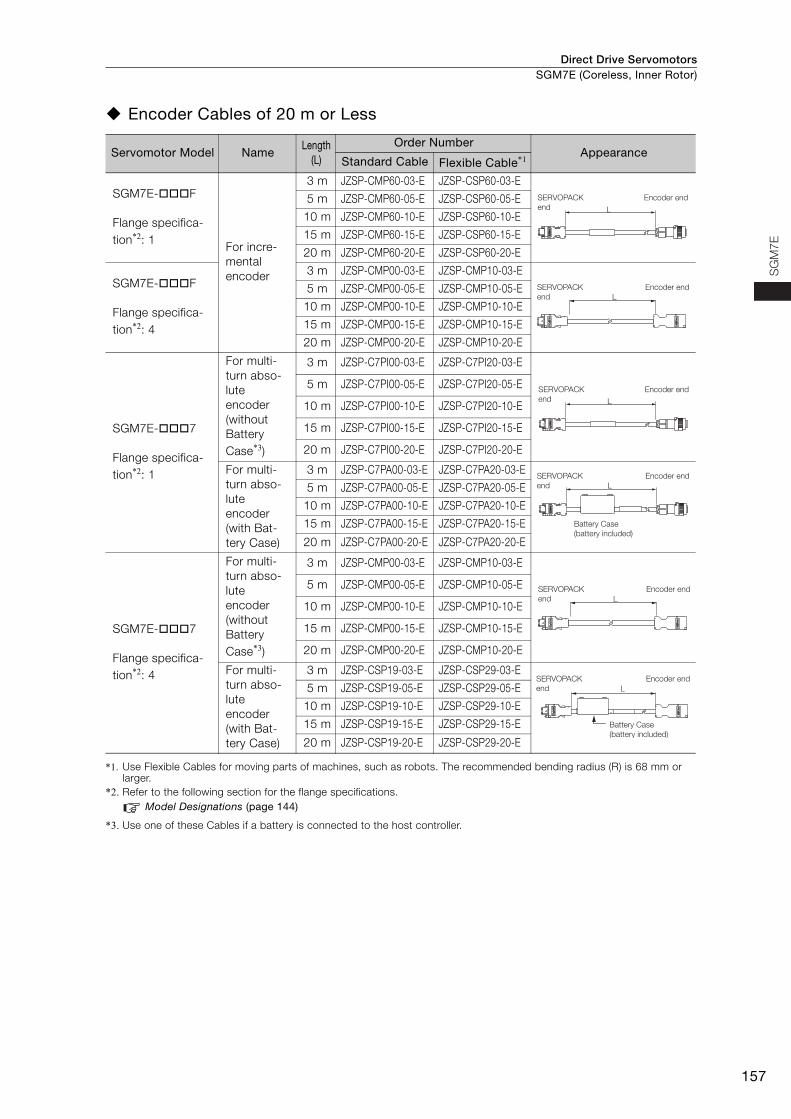
Direct Drive Servomotors SGM7E (Coreless, Inner Rotor)
157
SG
M7E
Encoder Cables of 20 m or Less
*1. Use Flexible Cables for moving parts of machines, such as robots. The recommended bending radius (R) is 68 mm or larger.
*2. Refer to the following section for the flange specifications.Model Designations (page 144)
*3. Use one of these Cables if a battery is connected to the host controller.
Servomotor Model NameLength
(L)
Order NumberAppearance
Standard Cable Flexible Cable*1
SGM7E-F
Flange specifica-tion*2: 1
For incre-mental encoder
3 m JZSP-CMP60-03-E JZSP-CSP60-03-E
5 m JZSP-CMP60-05-E JZSP-CSP60-05-E
10 m JZSP-CMP60-10-E JZSP-CSP60-10-E
15 m JZSP-CMP60-15-E JZSP-CSP60-15-E
20 m JZSP-CMP60-20-E JZSP-CSP60-20-E
SGM7E-F
Flange specifica-tion*2: 4
3 m JZSP-CMP00-03-E JZSP-CMP10-03-E
5 m JZSP-CMP00-05-E JZSP-CMP10-05-E
10 m JZSP-CMP00-10-E JZSP-CMP10-10-E
15 m JZSP-CMP00-15-E JZSP-CMP10-15-E
20 m JZSP-CMP00-20-E JZSP-CMP10-20-E
SGM7E-7
Flange specifica-tion*2: 1
For multi-turn abso-lute encoder (without Battery Case*3)
3 m JZSP-C7PI00-03-E JZSP-C7PI20-03-E
5 m JZSP-C7PI00-05-E JZSP-C7PI20-05-E
10 m JZSP-C7PI00-10-E JZSP-C7PI20-10-E
15 m JZSP-C7PI00-15-E JZSP-C7PI20-15-E
20 m JZSP-C7PI00-20-E JZSP-C7PI20-20-E
For multi-turn abso-lute encoder(with Bat-tery Case)
3 m JZSP-C7PA00-03-E JZSP-C7PA20-03-E
5 m JZSP-C7PA00-05-E JZSP-C7PA20-05-E
10 m JZSP-C7PA00-10-E JZSP-C7PA20-10-E
15 m JZSP-C7PA00-15-E JZSP-C7PA20-15-E
20 m JZSP-C7PA00-20-E JZSP-C7PA20-20-E
SGM7E-7
Flange specifica-tion*2: 4
For multi-turn abso-lute encoder (without Battery Case*3)
3 m JZSP-CMP00-03-E JZSP-CMP10-03-E
5 m JZSP-CMP00-05-E JZSP-CMP10-05-E
10 m JZSP-CMP00-10-E JZSP-CMP10-10-E
15 m JZSP-CMP00-15-E JZSP-CMP10-15-E
20 m JZSP-CMP00-20-E JZSP-CMP10-20-E
For multi-turn abso-lute encoder(with Bat-tery Case)
3 m JZSP-CSP19-03-E JZSP-CSP29-03-E
5 m JZSP-CSP19-05-E JZSP-CSP29-05-E
10 m JZSP-CSP19-10-E JZSP-CSP29-10-E
15 m JZSP-CSP19-15-E JZSP-CSP29-15-E
20 m JZSP-CSP19-20-E JZSP-CSP29-20-E
L
SERVOPACK end
Encoder end
LSERVOPACK end
Encoder end
L
SERVOPACK end
Encoder end
SERVOPACK end
Encoder end
Battery Case (battery included)
L
LSERVOPACK end
Encoder end
SERVOPACK end
Encoder end
Battery Case (battery included)
L
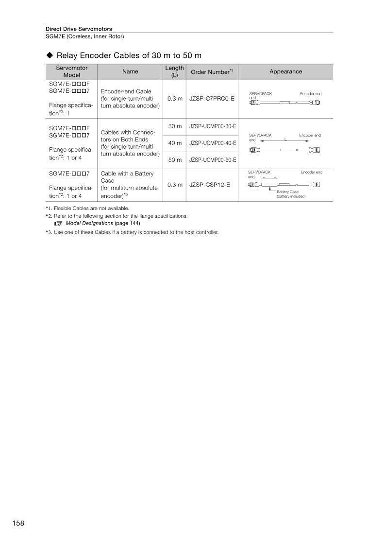
Direct Drive ServomotorsSGM7E (Coreless, Inner Rotor)
158
Relay Encoder Cables of 30 m to 50 m
*1. Flexible Cables are not available.
*2. Refer to the following section for the flange specifications.Model Designations (page 144)
*3. Use one of these Cables if a battery is connected to the host controller.
Servomotor Model
NameLength
(L) Order Number*1 Appearance
SGM7E-FSGM7E-7
Flange specifica-tion*2: 1
Encoder-end Cable (for single-turn/multi-turn absolute encoder)
0.3 m JZSP-C7PRC0-E
SGM7E-FSGM7E-7
Flange specifica-tion*2: 1 or 4
Cables with Connec-tors on Both Ends (for single-turn/multi-turn absolute encoder)
30 m JZSP-UCMP00-30-E
40 m JZSP-UCMP00-40-E
50 m JZSP-UCMP00-50-E
SGM7E-7
Flange specifica-tion*2: 1 or 4
Cable with a Battery Case(for multiturn absolute encoder)*3
0.3 m JZSP-CSP12-E
SERVOPACK end
Encoder end
LSERVOPACK end
Encoder end
SERVOPACK end
Encoder end
Battery Case (battery included)

159
MEMO
SG
M7E
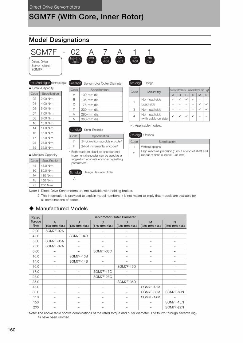
Direct Drive Servomotors
160
SGM7F (With Core, Inner Rotor)
Model Designations
Note: 1. Direct Drive Servomotors are not available with holding brakes.
2. This information is provided to explain model numbers. It is not meant to imply that models are available for all combinations of codes.
Manufactured Models
Note: The above table shows combinations of the rated torque and outer diameter. The fourth through seventh dig-its have been omitted.
Rated Torque
Nm
Servomotor Outer Diameter
A (100-mm dia.)
B (135-mm dia.)
C (175-mm dia.)
D (230-mm dia.)
M (280-mm dia.)
N (360-mm dia.)
2.00 SGM7F-02A – – – – –
4.00 – SGM7F-04B – – – –
5.00 SGM7F-05A – – – – –
7.00 SGM7F-07A – – – – –
8.00 – – SGM7F-08C – – –
10.0 – SGM7F-10B – – – –
14.0 – SGM7F-14B – – – –
16.0 – – – SGM7F-16D – –
17.0 – – SGM7F-17C – – –
25.0 – – SGM7F-25C – – –
35.0 – – – SGM7F-35D – –
45.0 – – – – SGM7F-45M –
80.0 – – – – SGM7F-80M SGM7F-80N
110 – – – – SGM7F-1AM –
150 – – – – – SGM7F-1EN
200 – – – – – SGM7F-2ZN
1A 110 Nm
1E 150 Nm
2Z 200 Nm
Small-Capacity
Medium-Capacity
SpecificationCode
SpecificationCode
02 2.00 Nm
04 4.00 Nm
05 5.00 Nm
07 7.00 Nm
08 8.00 Nm
10 10.0 Nm
14 14.0 Nm
16 16.0 Nm
17 17.0 Nm
25 25.0 Nm
35 35.0 Nm
45 45.0 Nm
80 80.0 Nm
4th digit
6th digit
7th digit Options
Without optionsHigh machine precision (runout at end of shaft and runout of shaft surface: 0.01 mm)
24-bit multiturn absolute encoder*24-bit incremental encoder*
A
5th digit Design Revision Order
Serial Encoder
Flange
SGM7F - 02 A 7 A 1 11st+2nd
digits
1st+2nd digits Rated Output
3rd digit
4th digit
5th digit
6th digit
7th digitDirect Drive
Servomotors: SGM7F
Code
Code
Specification
Specification7
F 1
2
A
B
C
D
M
N
3rd digit
100-mm dia.
Specification
135-mm dia.
175-mm dia.
230-mm dia.280-mm dia.360-mm dia.
Servomotor Outer Diameter
Code
A
B
C
D
M
N
1
3
4
Mounting
Non-load side
Load side
Non-load side
Non-load side (with cable on side)
: Applicable models.
Servomotor Outer Diameter Code (3rd Digit)Code
* Both multiturn absolute encoder and incremental encoder can be used as a single-turn absolute encoder by setting parameters.
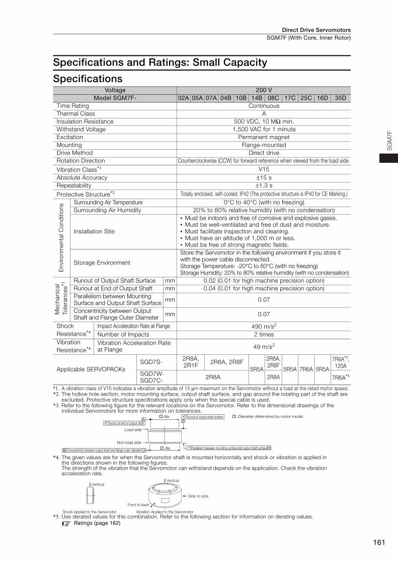
Direct Drive Servomotors SGM7F (With Core, Inner Rotor)
161
SG
M7
F
Specifications and Ratings: Small Capacity
Specifications
*1. A vibration class of V15 indicates a vibration amplitude of 15 μm maximum on the Servomotor without a load at the rated motor speed.*2. The hollow hole section, motor mounting surface, output shaft surface, and gap around the rotating part of the shaft are
excluded. Protective structure specifications apply only when the special cable is used. *3. Refer to the following figure for the relevant locations on the Servomotor. Refer to the dimensional drawings of the
individual Servomotors for more information on tolerances.
*4. The given values are for when the Servomotor shaft is mounted horizontally and shock or vibration is applied in the directions shown in the following figures.The strength of the vibration that the Servomotor can withstand depends on the application. Check the vibration acceleration rate.
*5. Use derated values for this combination. Refer to the following section for information on derating values.Ratings (page 162)
Voltage 200 VModel SGM7F- 02A 05A 07A 04B 10B 14B 08C 17C 25C 16D 35D
Time Rating Continuous Thermal Class AInsulation Resistance 500 VDC, 10 MΩ min. Withstand Voltage 1,500 VAC for 1 minute Excitation Permanent magnet Mounting Flange-mounted Drive Method Direct drive Rotation Direction Counterclockwise (CCW) for forward reference when viewed from the load side
Vibration Class*1 V15Absolute Accuracy ±15 s Repeatability ±1.3 s
Protective Structure*2 Totally enclosed, self-cooled, IP42 (The protective structure is IP40 for CE Marking.)
Env
ironm
enta
l Con
diti
ons Surrounding Air Temperature 0°C to 40°C (with no freezing)
Surrounding Air Humidity 20% to 80% relative humidity (with no condensation)
Installation Site
• Must be indoors and free of corrosive and explosive gases. • Must be well-ventilated and free of dust and moisture. • Must facilitate inspection and cleaning. • Must have an altitude of 1,000 m or less.• Must be free of strong magnetic fields.
Storage Environment
Store the Servomotor in the following environment if you store it with the power cable disconnected. Storage Temperature: -20°C to 60°C (with no freezing)Storage Humidity: 20% to 80% relative humidity (with no condensation)
Mec
hani
cal
Tol
eran
ces*3
Runout of Output Shaft Surface mm 0.02 (0.01 for high machine precision option) Runout at End of Output Shaft mm 0.04 (0.01 for high machine precision option) Parallelism between Mounting Surface and Output Shaft Surface mm 0.07
Concentricity between Output Shaft and Flange Outer Diameter mm 0.07
Shock Resistance*4
Impact Acceleration Rate at Flange 490 m/s2
Number of Impacts 2 times Vibration Resistance*4
Vibration Acceleration Rate at Flange 49 m/s2
Applicable SERVOPACKsSGD7S- 2R8A,
2R1F 2R8A, 2R8F5R5A
2R8A, 2R8F
5R5A 7R6A 5R5A
7R6A*5, 120A
SGD7W-SGD7C- 2R8A 2R8A 7R6A*5
A
A B
B
Runout at end of output shaft
dia.
Load side
Non-load side
Concentricity between output shaft and flange outer diameter dia. Parallelism between mounting surface and output shaft surface
Runout of output shaft surface : Diameter determined by motor model.
Side to side
Front to back
Vertical
Shock Applied to the Servomotor Vibration Applied to the Servomotor
Vertical
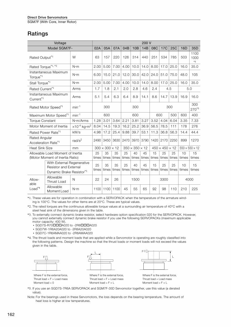
Direct Drive ServomotorsSGM7F (With Core, Inner Rotor)
162
Ratings
*1. These values are for operation in combination with a SERVOPACK when the temperature of the armature wind-ing is 100°C. The values for other items are at 20°C. These are typical values.
*2. The rated torques are the continuous allowable torque values at a surrounding air temperature of 40°C with a steel heat sink of the dimensions given in the table.
*3. To externally connect dynamic brake resistor, select hardware option specification 020 for the SERVOPACK. However, you cannot externally connect dynamic brake resistor if you use the following SERVOPACKs (maximum applicable motor capacity: 400 W).• SGD7S-R70A020 to -2R8A020• SGD7W-1R6A20A020 to -2R8A20A020• SGD7C-1R6AMAA020 to -2R8AMAA020
*4. The thrust loads and moment loads that are applied while a Servomotor is operating are roughly classified into the following patterns. Design the machine so that the thrust loads or moment loads will not exceed the values given in the table.
*5. If you use an SGD7S-7R6A SERVOPACK and SGM7F-35D Servomotor together, use this value (a derated value).
Note: For the bearings used in these Servomotors, the loss depends on the bearing temperature. The amount of heat loss is higher at low temperatures.
Voltage 200 V
Model SGM7F- 02A 05A 07A 04B 10B 14B 08C 17C 25C 16D 35D
Rated Output*1 W 63 157 220 126 314 440 251 534 785 50311001000
*5
Rated Torque*1, *2 Nm 2.00 5.00 7.00 4.00 10.0 14.0 8.00 17.0 25.0 16.0 35.0
Instantaneous Maximum Torque*1 Nm 6.00 15.0 21.0 12.0 30.0 42.0 24.0 51.0 75.0 48.0 105
Stall Torque*1 Nm 2.00 5.00 7.00 4.00 10.0 14.0 8.00 17.0 25.0 16.0 35.0
Rated Current*1 Arms 1.7 1.8 2.1 2.0 2.8 4.6 2.4 4.5 5.0
Instantaneous Maximum Current*1 Arms 5.1 5.4 6.3 6.4 8.9 14.1 8.6 14.7 13.9 16.9 16.0
Rated Motor Speed*1 min-1 300 300 300300
270*5
Maximum Motor Speed*1 min-1 600 600 600 500 600 400
Torque Constant Nm/Arms 1.28 3.01 3.64 2.21 3.81 3.27 3.52 4.04 6.04 3.35 7.33
Motor Moment of Inertia ×10-4 kgm2 8.04 14.5 19.3 16.2 25.2 36.9 56.5 78.5 111 178 276
Rated Power Rate*1 kW/s 4.98 17.2 25.4 9.88 39.7 53.1 11.3 36.8 56.3 14.4 44.4
Rated Angular Acceleration Rate*1 rad/s2 2490 3450 3630 2470 3970 3790 1420 2170 2250 899 1270
Heat Sink Size mm 300 × 300 × 12 350 × 350 × 12 450 × 450 × 12 550 × 550 × 12
Allowable Load Moment of Inertia (Motor Moment of Inertia Ratio)
25 times
35 times
35 times
25 times
40 times
45 times
15 times
25 times
25 times
10 times
15 times
With External Regenerative Resistor and External Dynamic Brake Resistor*3
25 times
35 times
35 times
25 times
40 times
45 times
15 times
25 times
25 times
10 times
15 times
Allow-able Load*4
Allowable Thrust Load
N 22 24 26 1500 3300 4000
Allowable Moment Load
Nm 1100 1100 1100 45 55 65 92 98 110 210 225
F
F
LF
L
Where F is the external force,
Thrust load = F + Load mass
Moment load = 0
Where F is the external force,
Thrust load = F + Load mass
Moment load = F × L
Where F is the external force,
Thrust load = Load mass
Moment load = F × L
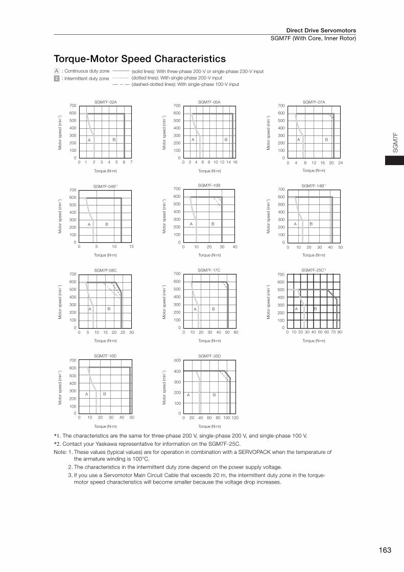
Direct Drive Servomotors SGM7F (With Core, Inner Rotor)
163
SG
M7
F
Torque-Motor Speed Characteristics
*1. The characteristics are the same for three-phase 200 V, single-phase 200 V, and single-phase 100 V.
*2. Contact your Yaskawa representative for information on the SGM7F-25C.
Note: 1. These values (typical values) are for operation in combination with a SERVOPACK when the temperature of the armature winding is 100°C.
2. The characteristics in the intermittent duty zone depend on the power supply voltage.
3. If you use a Servomotor Main Circuit Cable that exceeds 20 m, the intermittent duty zone in the torque-motor speed characteristics will become smaller because the voltage drop increases.
SGM7F-08C
0 5 10 15 20 25 30
0
100
200
300
400
500
600
700
A B
SGM7F-17C
0 10 20 30 40 50 600
100
200
300
400
500
600
700
A B
SGM7F-04B*1
0
100
200
300
400
500
600
700
0 5 10 15
A B
SGM7F-25C*2
0 10 20 30 40 50 60 70 800
100
200
300
400
500
600
700
A B
SGM7F-10B
0 10 20 30 40
0
100
200
300
400
500
600
700
A B
SGM7F-14B*1
0 10 20 30 40 50
0
100
200
300
400
500
600
700
A B
SGM7F-16D
0 10 20 30 40 500
100
200
300
400
500
600
700
A B
0 20 40 60 80 100 120
SGM7F-35D
0
100
200
300
400
500
A B
A :
B :
(dashed-dotted lines): With single-phase 100-V input
(solid lines): With three-phase 200-V or single-phase 230-V input
(dotted lines): With single-phase 200-V inputIntermittent duty zone
Continuous duty zone
Torque (N�m)
Mo
tor
sp
eed
(m
in-1)
Mo
tor
sp
eed
(m
in-1)
Torque (N�m)
Torque (N�m)
Mo
tor
sp
eed
(m
in-1)
Mo
tor
sp
eed
(m
in-1)
Torque (N�m)
Torque (N�m)
Mo
tor
sp
eed
(m
in-1)
Mo
tor
sp
eed
(m
in-1)
Torque (N�m)
Mo
tor
sp
eed
(m
in-1)
Torque (N�m)
Mo
tor
sp
eed
(m
in-1)
Torque (N�m)
Mo
tor
sp
eed
(m
in-1)
Torque (N�m)
Mo
tor
sp
eed
(m
in-1)
Torque (N�m)
Mo
tor
sp
eed
(m
in-1)
SGM7F-02A
0
100
200
300
400
500
600
700
0 2 3 4 61 5 7 0 4 6 8 122 10 14 16
A B
SGM7F-05A700
600
500
400
300
200
100
0
700
600
500
400
300
200
100
0
A B
SGM7F-07A
0 84 12 16 20 24
A B
Torque (N�m)
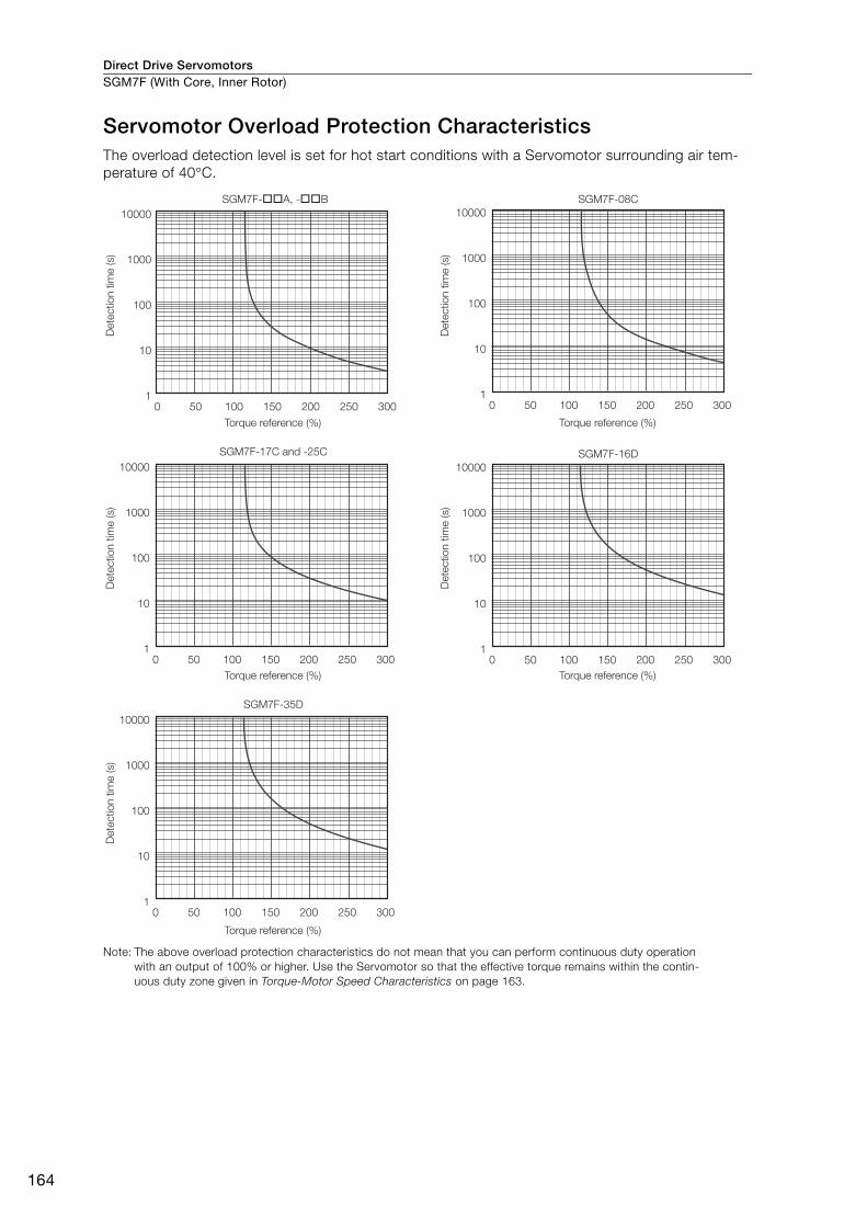
Direct Drive ServomotorsSGM7F (With Core, Inner Rotor)
164
Servomotor Overload Protection Characteristics The overload detection level is set for hot start conditions with a Servomotor surrounding air tem-perature of 40°C.
Note: The above overload protection characteristics do not mean that you can perform continuous duty operation with an output of 100% or higher. Use the Servomotor so that the effective torque remains within the contin-uous duty zone given in Torque-Motor Speed Characteristics on page 163.
10000
1000
100
10
1
SGM7F-��A, -��B SGM7F-08C
0 50 100 150 200 250 300
10000
1000
100
10
1
SGM7F-17C and -25C
0 50 100 150 200 250 300
10000
1000
100
10
1
SGM7F-35D
0 50 100 150 200 250 300
10000
1000
100
10
10 50 100 150 200 250 300
SGM7F-16D
10000
1000
100
10
10 50 100 150 200 250 300
Dete
ctio
n t
ime (s)
Torque reference (%)
Dete
ctio
n t
ime (s)
Torque reference (%)
Dete
ctio
n t
ime (s)
Torque reference (%)
Dete
ctio
n t
ime (s)
Torque reference (%)
Dete
ctio
n t
ime (s)
Torque reference (%)
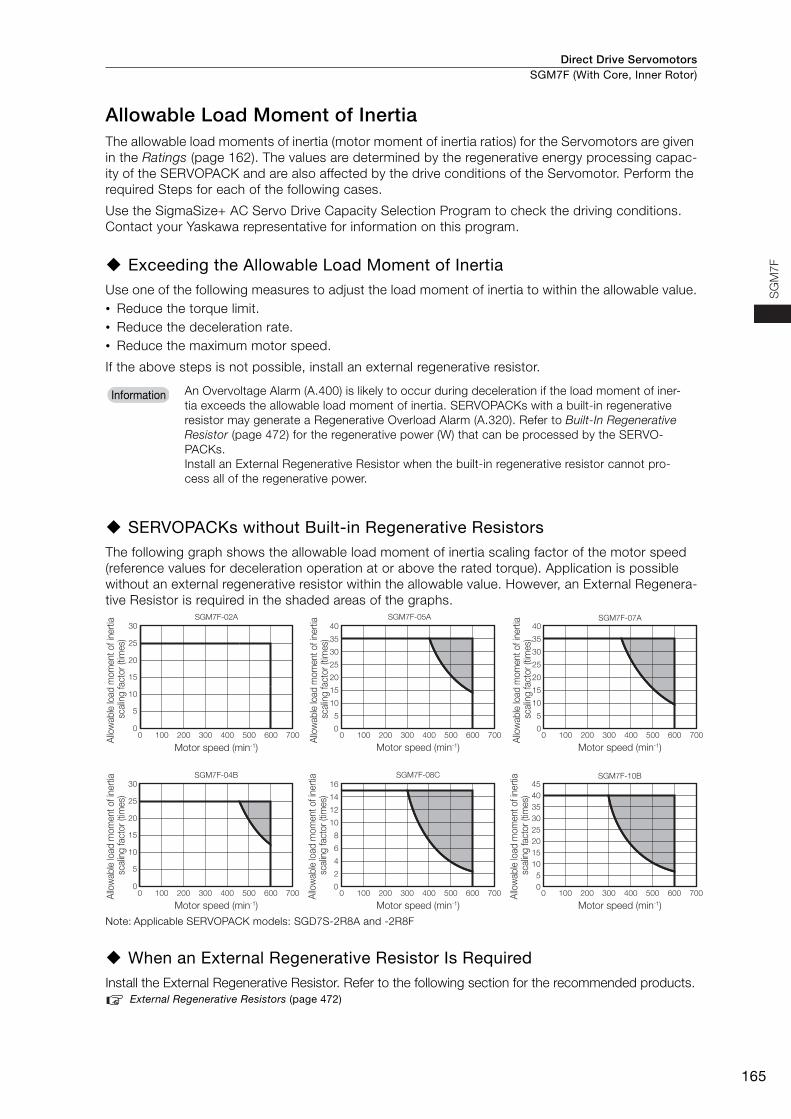
Direct Drive Servomotors SGM7F (With Core, Inner Rotor)
165
SG
M7
F
Allowable Load Moment of InertiaThe allowable load moments of inertia (motor moment of inertia ratios) for the Servomotors are given in the Ratings (page 162). The values are determined by the regenerative energy processing capac-ity of the SERVOPACK and are also affected by the drive conditions of the Servomotor. Perform the required Steps for each of the following cases.
Use the SigmaSize+ AC Servo Drive Capacity Selection Program to check the driving conditions. Contact your Yaskawa representative for information on this program.
Exceeding the Allowable Load Moment of InertiaUse one of the following measures to adjust the load moment of inertia to within the allowable value.• Reduce the torque limit.• Reduce the deceleration rate.• Reduce the maximum motor speed.
If the above steps is not possible, install an external regenerative resistor.
SERVOPACKs without Built-in Regenerative ResistorsThe following graph shows the allowable load moment of inertia scaling factor of the motor speed (reference values for deceleration operation at or above the rated torque). Application is possible without an external regenerative resistor within the allowable value. However, an External Regenera-tive Resistor is required in the shaded areas of the graphs.
Note: Applicable SERVOPACK models: SGD7S-2R8A and -2R8F
When an External Regenerative Resistor Is RequiredInstall the External Regenerative Resistor. Refer to the following section for the recommended products.
External Regenerative Resistors (page 472)
An Overvoltage Alarm (A.400) is likely to occur during deceleration if the load moment of iner-tia exceeds the allowable load moment of inertia. SERVOPACKs with a built-in regenerative resistor may generate a Regenerative Overload Alarm (A.320). Refer to Built-In Regenerative Resistor (page 472) for the regenerative power (W) that can be processed by the SERVO-PACKs. Install an External Regenerative Resistor when the built-in regenerative resistor cannot pro-cess all of the regenerative power.
Information
0
5
10
15
20
25
30
0 100 200 300 400 500 600 700 0 100 200 300 400 500 600 700 0 100 200 300 400 500 600 700
SGM7F-04B
0
2
4
6
8
10
12
14
16SGM7F-08C
05
1015202530354045
SGM7F-10B
Motor speed (min-1)
Allo
wab
le lo
ad m
omen
t of i
nerti
a sc
alin
g fa
ctor
(tim
es)
Allo
wab
le lo
ad m
omen
t of i
nerti
a sc
alin
g fa
ctor
(tim
es)
Allo
wab
le lo
ad m
omen
t of i
nerti
a sc
alin
g fa
ctor
(tim
es)
Allo
wab
le lo
ad m
omen
t of i
nerti
a sc
alin
g fa
ctor
(tim
es)
Motor speed (min-1)
Allo
wab
le lo
ad m
omen
t of i
nerti
a sc
alin
g fa
ctor
(tim
es)
Motor speed (min-1)
Allo
wab
le lo
ad m
omen
t of i
nerti
a sc
alin
g fa
ctor
(tim
es)
0
5
10
15
20
25
30
0 100 200 300 400 500 600 700 0 100 200 300 400 500 600 700
SGM7F-02A
0
5
10
15
20
25
30
35
40SGM7F-05A
0 100 200 300 400 500 600 7000
5
10
15
20
25
30
35
40SGM7F-07A
Motor speed (min-1)Motor speed (min-1)Motor speed (min-1)
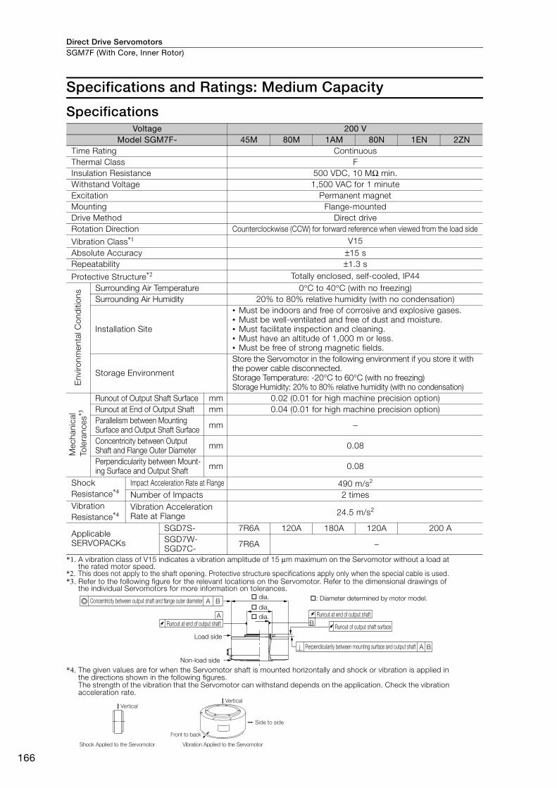
Direct Drive ServomotorsSGM7F (With Core, Inner Rotor)
166
Specifications and Ratings: Medium Capacity
Specifications
*1. A vibration class of V15 indicates a vibration amplitude of 15 μm maximum on the Servomotor without a load at the rated motor speed.
*2. This does not apply to the shaft opening. Protective structure specifications apply only when the special cable is used. *3. Refer to the following figure for the relevant locations on the Servomotor. Refer to the dimensional drawings of
the individual Servomotors for more information on tolerances.
*4. The given values are for when the Servomotor shaft is mounted horizontally and shock or vibration is applied in the directions shown in the following figures.The strength of the vibration that the Servomotor can withstand depends on the application. Check the vibration acceleration rate.
Voltage 200 VModel SGM7F- 45M 80M 1AM 80N 1EN 2ZN
Time Rating Continuous Thermal Class FInsulation Resistance 500 VDC, 10 MΩ min. Withstand Voltage 1,500 VAC for 1 minute Excitation Permanent magnet Mounting Flange-mounted Drive Method Direct drive Rotation Direction Counterclockwise (CCW) for forward reference when viewed from the load side
Vibration Class*1 V15Absolute Accuracy ±15 s Repeatability ±1.3 s
Protective Structure*2 Totally enclosed, self-cooled, IP44
Env
ironm
enta
l Con
diti
ons Surrounding Air Temperature 0°C to 40°C (with no freezing)
Surrounding Air Humidity 20% to 80% relative humidity (with no condensation)
Installation Site
• Must be indoors and free of corrosive and explosive gases.• Must be well-ventilated and free of dust and moisture.• Must facilitate inspection and cleaning.• Must have an altitude of 1,000 m or less.• Must be free of strong magnetic fields.
Storage Environment
Store the Servomotor in the following environment if you store it with the power cable disconnected.Storage Temperature: -20°C to 60°C (with no freezing) Storage Humidity: 20% to 80% relative humidity (with no condensation)
Mec
hani
cal
Tol
eran
ces*3
Runout of Output Shaft Surface mm 0.02 (0.01 for high machine precision option)Runout at End of Output Shaft mm 0.04 (0.01 for high machine precision option)Parallelism between Mounting Surface and Output Shaft Surface mm −
Concentricity between Output Shaft and Flange Outer Diameter mm 0.08
Perpendicularity between Mount-ing Surface and Output Shaft mm 0.08
Shock Resistance*4
Impact Acceleration Rate at Flange 490 m/s2
Number of Impacts 2 times Vibration Resistance*4
Vibration Acceleration Rate at Flange 24.5 m/s2
Applicable SERVOPACKs
SGD7S- 7R6A 120A 180A 120A 200 ASGD7W-SGD7C- 7R6A −
B
A
A
A B
B
Runout at end of output shaft
Runout of output shaft surface
Perpendicularity between mounting surface and output shaft
Concentricity between output shaft and flange outer diameter
Runout at end of output shaft
Load side
Non-load side
dia. : Diameter determined by motor model. dia. dia.
Side to side
Front to back
Vertical
Shock Applied to the Servomotor Vibration Applied to the Servomotor
Vertical
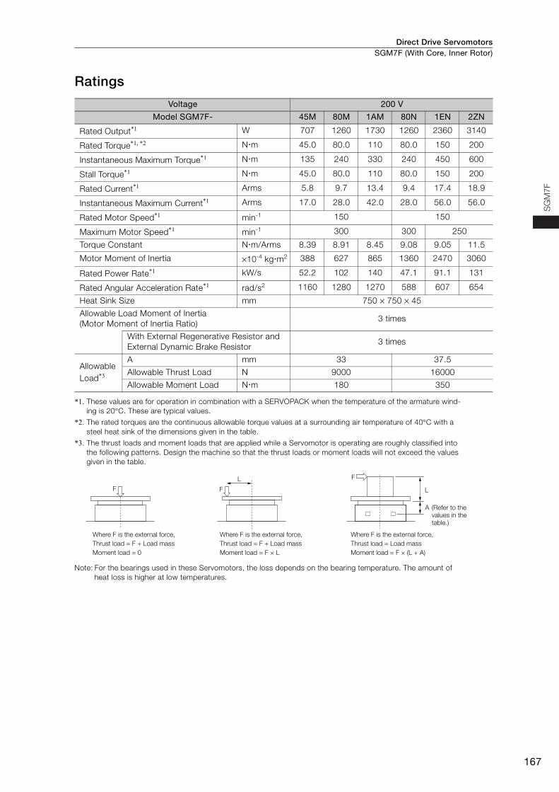
Direct Drive Servomotors SGM7F (With Core, Inner Rotor)
167
SG
M7
F
Ratings
*1. These values are for operation in combination with a SERVOPACK when the temperature of the armature wind-ing is 20°C. These are typical values.
*2. The rated torques are the continuous allowable torque values at a surrounding air temperature of 40°C with a steel heat sink of the dimensions given in the table.
*3. The thrust loads and moment loads that are applied while a Servomotor is operating are roughly classified into the following patterns. Design the machine so that the thrust loads or moment loads will not exceed the values given in the table.
Note: For the bearings used in these Servomotors, the loss depends on the bearing temperature. The amount of heat loss is higher at low temperatures.
Voltage 200 V
Model SGM7F- 45M 80M 1AM 80N 1EN 2ZN
Rated Output*1 W 707 1260 1730 1260 2360 3140
Rated Torque*1, *2 Nm 45.0 80.0 110 80.0 150 200
Instantaneous Maximum Torque*1 Nm 135 240 330 240 450 600
Stall Torque*1 Nm 45.0 80.0 110 80.0 150 200
Rated Current*1 Arms 5.8 9.7 13.4 9.4 17.4 18.9
Instantaneous Maximum Current*1 Arms 17.0 28.0 42.0 28.0 56.0 56.0
Rated Motor Speed*1 min-1 150 150
Maximum Motor Speed*1 min-1 300 300 250
Torque Constant Nm/Arms 8.39 8.91 8.45 9.08 9.05 11.5
Motor Moment of Inertia ×10-4 kgm2 388 627 865 1360 2470 3060
Rated Power Rate*1 kW/s 52.2 102 140 47.1 91.1 131
Rated Angular Acceleration Rate*1 rad/s2 1160 1280 1270 588 607 654
Heat Sink Size mm 750 × 750 × 45
Allowable Load Moment of Inertia (Motor Moment of Inertia Ratio)
3 times
With External Regenerative Resistor and External Dynamic Brake Resistor
3 times
Allowable Load*3
A mm 33 37.5
Allowable Thrust Load N 9000 16000
Allowable Moment Load Nm 180 350
F F
L F
L
Where F is the external force,
Thrust load = F + Load mass
Moment load = 0
Where F is the external force,
Thrust load = F + Load mass
Moment load = F × L
Where F is the external force,
Thrust load = Load mass
Moment load = F × (L + A)
A (Refer to the
values in the
table.)
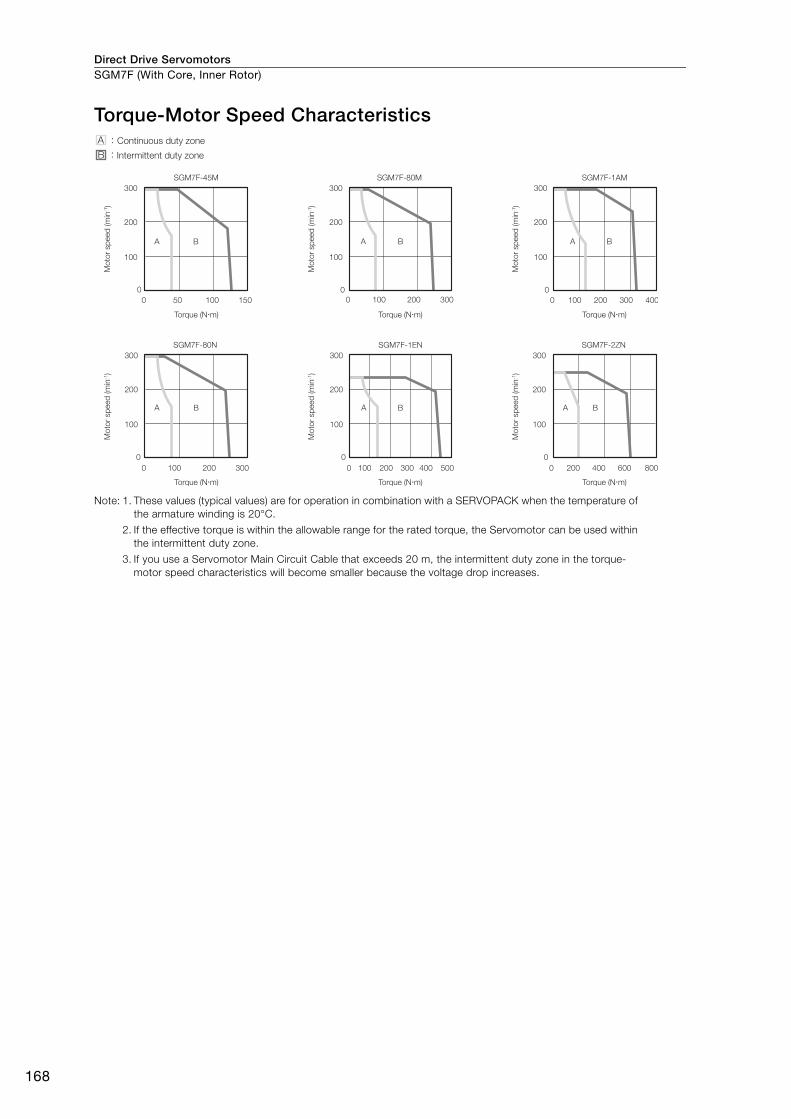
Direct Drive ServomotorsSGM7F (With Core, Inner Rotor)
168
Torque-Motor Speed Characteristics
Note: 1. These values (typical values) are for operation in combination with a SERVOPACK when the temperature of the armature winding is 20°C.
2. If the effective torque is within the allowable range for the rated torque, the Servomotor can be used within the intermittent duty zone.
3. If you use a Servomotor Main Circuit Cable that exceeds 20 m, the intermittent duty zone in the torque-motor speed characteristics will become smaller because the voltage drop increases.
A
0 50 100 150
0
100
200
300
B A
0 100 200 300
0
100
200
300
B
SGM7F-45M SGM7F-80M
A
0 100 200 300 400
0
100
200
300
B
A
0 100 200 300
0
100
200
300
B
SGM7F-1AM
SGM7F-80N
A
0 100 200 300 400 500
0
100
200
300
B A
0 200 400 600 800
0
100
200
300
B
SGM7F-1EN SGM7F-2ZN
A :
B :
Continuous duty zone
Intermittent duty zone
Torque (N�m)
Mo
tor
sp
eed
(m
in-1)
Torque (N�m)M
oto
r sp
eed
(m
in-1)
Torque (N�m)
Mo
tor
sp
eed
(m
in-1)
Torque (N�m)
Mo
tor
sp
eed
(m
in-1)
Torque (N�m)
Mo
tor
sp
eed
(m
in-1)
Torque (N�m)
Mo
tor
sp
eed
(m
in-1)
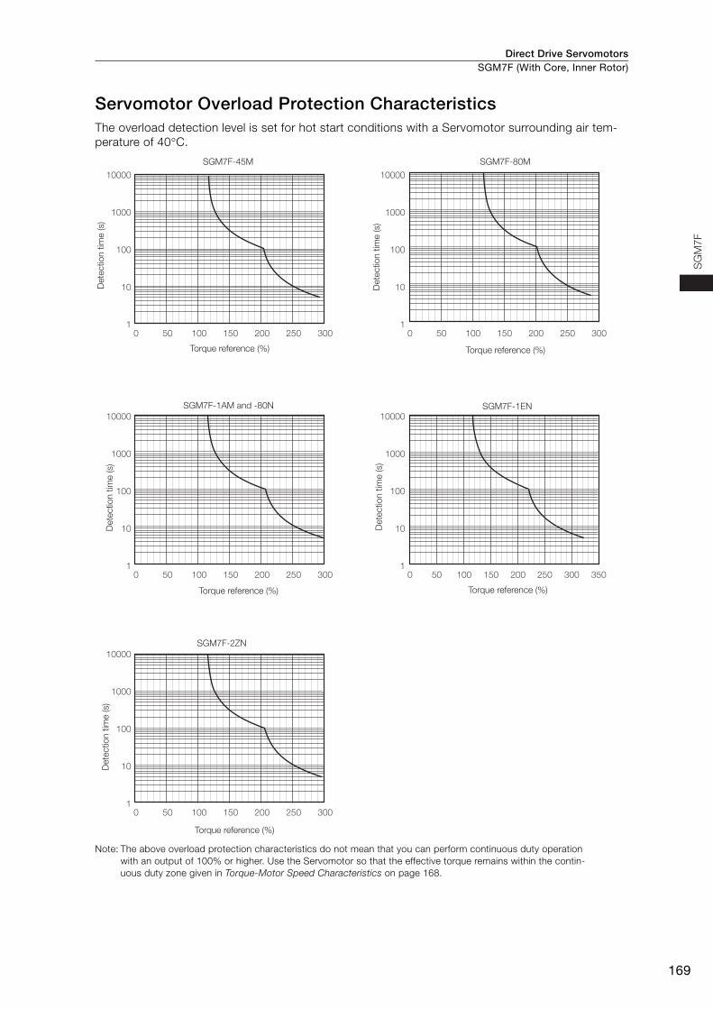
Direct Drive Servomotors SGM7F (With Core, Inner Rotor)
169
SG
M7
F
Servomotor Overload Protection CharacteristicsThe overload detection level is set for hot start conditions with a Servomotor surrounding air tem-perature of 40°C.
Note: The above overload protection characteristics do not mean that you can perform continuous duty operation with an output of 100% or higher. Use the Servomotor so that the effective torque remains within the contin-uous duty zone given in Torque-Motor Speed Characteristics on page 168.
10000
1000
100
10
1
10000
1000
100
10
1
10000
1000
100
10
1
10000
1000
100
10
1
10000
1000
100
10
1
0 50 100 150 200 250 300 0 50 100 150 200 250 300
0 50 100 150 200 250 300
0 50 100 150 200 250 300
0 50 100 150 200 250 300 350
SGM7F-45M SGM7F-80M
SGM7F-1AM and -80N
SGM7F-2ZN
SGM7F-1EN
Dete
ctio
n t
ime (s)
Torque reference (%)
Dete
ctio
n t
ime (s)
Torque reference (%)
Dete
ctio
n t
ime (s)
Torque reference (%)
Dete
ctio
n t
ime (s)
Torque reference (%)
Dete
ctio
n t
ime (s)
Torque reference (%)
Direct Drive ServomotorsSGM7F (With Core, Inner Rotor)
170
Allowable Load Moment of InertiaThe allowable load moments of inertia (motor moment of inertia ratios) for the Servomotors are given in the Ratings (page 167). The values are determined by the regenerative energy processing capac-ity of the SERVOPACK and are also affected by the drive conditions of the Servomotor. Perform the required Steps for each of the following cases.
Use the SigmaSize+ AC Servo Drive Capacity Selection Program to check the driving conditions. Contact your Yaskawa representative for information on this program.
Exceeding the Allowable Load Moment of InertiaUse one of the following measures to adjust the load moment of inertia to within the allowable value.• Reduce the torque limit.• Reduce the deceleration rate.• Reduce the maximum motor speed.
If the above steps is not possible, install an external regenerative resistor.
When an External Regenerative Resistor Is RequiredInstall the External Regenerative Resistor. Refer to the following section for the recommended products.
External Regenerative Resistors (page 472)
An Overvoltage Alarm (A.400) is likely to occur during deceleration if the load moment of iner-tia exceeds the allowable load moment of inertia. SERVOPACKs with a built-in regenerative resistor may generate a Regenerative Overload Alarm (A.320). Refer to Built-In Regenerative Resistor (page 472) for the regenerative power (W) that can be processed by the SERVO-PACKs.Install an External Regenerative Resistor when the built-in regenerative resistor cannot pro-cess all of the regenerative power.
Information
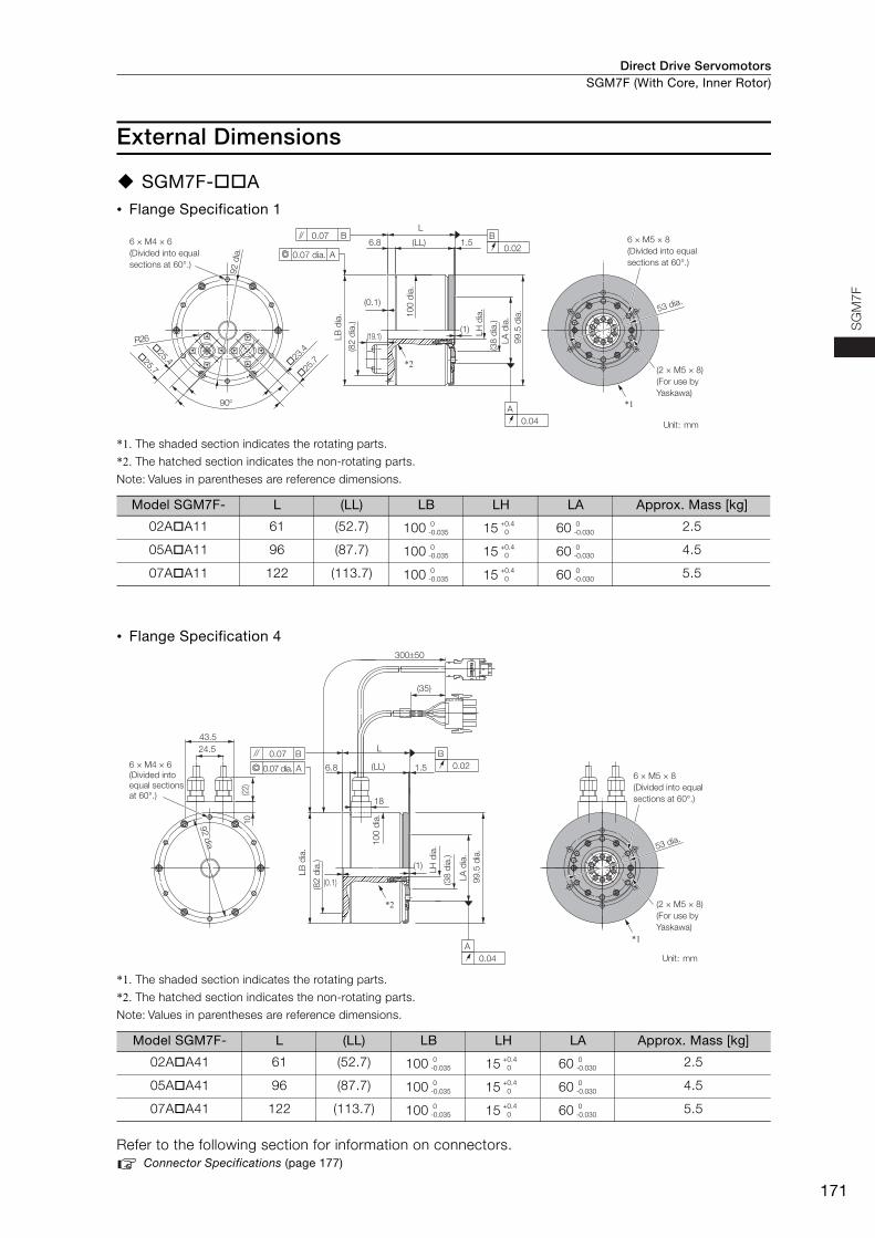
Direct Drive Servomotors SGM7F (With Core, Inner Rotor)
171
SG
M7
F
External Dimensions
SGM7F-A• Flange Specification 1
*1. The shaded section indicates the rotating parts.
*2. The hatched section indicates the non-rotating parts.
Note: Values in parentheses are reference dimensions.
• Flange Specification 4
*1. The shaded section indicates the rotating parts.
*2. The hatched section indicates the non-rotating parts.
Note: Values in parentheses are reference dimensions.
Refer to the following section for information on connectors. Connector Specifications (page 177)
Model SGM7F- L (LL) LB LH LA Approx. Mass [kg]
02AA11 61 (52.7) 100 15 60 2.5
05AA11 96 (87.7) 100 15 60 4.5
07AA11 122 (113.7) 100 15 60 5.5
Model SGM7F- L (LL) LB LH LA Approx. Mass [kg]
02AA41 61 (52.7) 100 15 60 2.5
05AA41 96 (87.7) 100 15 60 4.5
07AA41 122 (113.7) 100 15 60 5.5
6 × M4 × 6
(Divided into equal
sections at 60°.)
(2 × M5 × 8)
(For use by
Yaskawa)
*1
*223
.4
25
.7
25.4
25.7
(1)
1.56.8
90
R26
(LL)
L
(19.1)
(0.1)
A
0.07 B
0.07 dia.
LB
dia
.
(82
dia
.)
92 d
ia.
99
.5 d
ia.
10
0 d
ia.
LA
dia
.
(38
dia
.)
LH
dia
. 53 dia.
Unit: mm
B
0.02
A
0.04
6 × M5 × 8
(Divided into equal
sections at 60°.)
0-0.035
+0.40
0-0.030
0-0.035
+0.40
0-0.030
0-0.035
+0.40
0-0.030
6 × M4 × 6
(Divided into
equal sections
at 60°.)
6 × M5 × 8
(Divided into equal
sections at 60°.)
(2 × M5 × 8)
(For use by
Yaskawa)
1.56.8 (LL)
L
30050
(35)
18
43.5
24.5
10
(22)
A
0.04
0.07 B
A0.07 dia.
92 d
ia.
92 d
ia.
(0.1)
LB
dia
.
(82
dia
.)
*1
53 dia.
Unit: mm
B
0.02
*2
(1)
10
0 d
ia.
99
.5 d
ia.
LA
dia
.
(38
dia
.)
LH
dia
.
92 d
ia.
0-0.035
+0.40
0-0.030
0-0.035
+0.40
0-0.030
0-0.035
+0.40
0-0.030
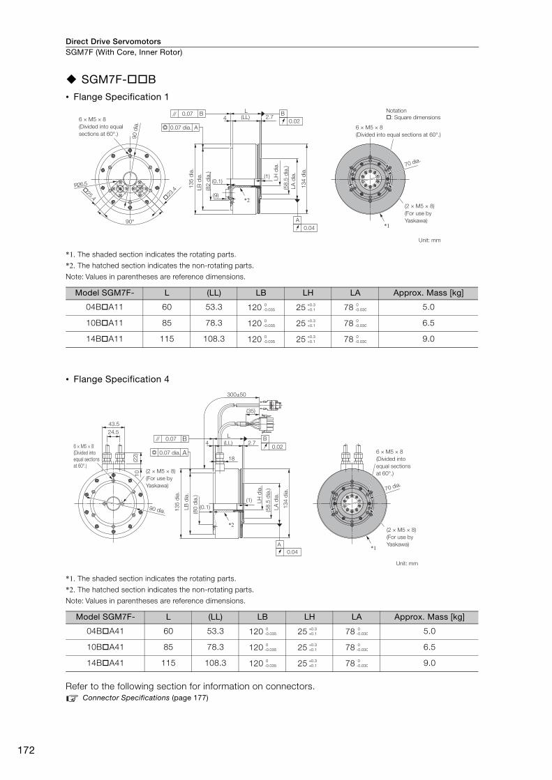
Direct Drive ServomotorsSGM7F (With Core, Inner Rotor)
172
SGM7F-B• Flange Specification 1
*1. The shaded section indicates the rotating parts.
*2. The hatched section indicates the non-rotating parts.
Note: Values in parentheses are reference dimensions.
• Flange Specification 4
*1. The shaded section indicates the rotating parts.
*2. The hatched section indicates the non-rotating parts.
Note: Values in parentheses are reference dimensions.
Refer to the following section for information on connectors. Connector Specifications (page 177)
Model SGM7F- L (LL) LB LH LA Approx. Mass [kg]
04BA11 60 53.3 120 25 78 5.0
10BA11 85 78.3 120 25 78 6.5
14BA11 115 108.3 120 25 78 9.0
Model SGM7F- L (LL) LB LH LA Approx. Mass [kg]
04BA41 60 53.3 120 25 78 5.0
10BA41 85 78.3 120 25 78 6.5
14BA41 115 108.3 120 25 78 9.0
23
.4
25.4
(1)
2.74
90°
R26.5
(LL)L
(9)
(0.1)
A
0.04
B
0.02
A
0.07 B
*1
*2
6 × M5 × 8
(Divided into equal
sections at 60°.)
(82
dia
.)
13
4 d
ia.
(58
.5 d
ia.)
LB
dia
.
13
5 d
ia.
0.07 dia. 6 × M5 × 8
(Divided into equal sections at 60°.)
(2 × M5 × 8)
(For use by
Yaskawa)
70 dia.
Unit: mm
90 d
ia.
LA
dia
.
LH
dia
.
Notation
: Square dimensions
0-0.035
+0.3+0.1
0-0.030
0-0.035
+0.3+0.1
0-0.030
0-0.035
+0.3+0.1
0-0.030
(1)
2.7(LL)
L
300±50
(35)
18
4
(0.1)
43.5
24.5
10
(22
)
A
0.04
B
0.02
0.07 B
A
90 dia.
*1
*2
6 × M5 × 8
(Divided into
equal sections
at 60°.)
0.07 dia.
(2 × M5 × 8)
(For use by
Yaskawa)
13
4 d
ia.
(58
.5 d
ia.)
LH
dia
.
(80
dia
.)
13
5 d
ia.
6 × M5 × 8
(Divided into
equal sections
at 60°.)
(2 × M5 × 8)
(For use by
Yaskawa)
Unit: mm
70 dia.
LB
dia
.
LA
dia
.
0-0.035
+0.3+0.1
0-0.030
0-0.035
+0.3+0.1
0-0.030
0-0.035
+0.3+0.1
0-0.030
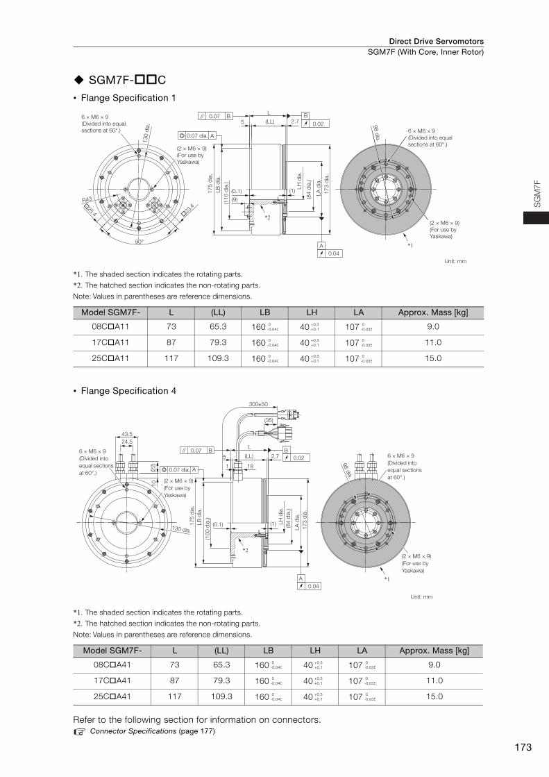
Direct Drive Servomotors SGM7F (With Core, Inner Rotor)
173
SG
M7
F
SGM7F-C
• Flange Specification 1
*1. The shaded section indicates the rotating parts.
*2. The hatched section indicates the non-rotating parts.
Note: Values in parentheses are reference dimensions.
• Flange Specification 4
*1. The shaded section indicates the rotating parts.
*2. The hatched section indicates the non-rotating parts.
Note: Values in parentheses are reference dimensions.
Refer to the following section for information on connectors.Connector Specifications (page 177)
Model SGM7F- L (LL) LB LH LA Approx. Mass [kg]
08CA11 73 65.3 160 40 107 9.0
17CA11 87 79.3 160 40 107 11.0
25CA11 117 109.3 160 40 107 15.0
Model SGM7F- L (LL) LB LH LA Approx. Mass [kg]
08CA41 73 65.3 160 40 107 9.0
17CA41 87 79.3 160 40 107 11.0
25CA41 117 109.3 160 40 107 15.0
23
.4
25.4
2.75
R43
(0.1) (1)
90°
L
(LL)
(9)
B
0.02
A
0.04
0.07 B
A
17
3 d
ia.
*1
*2
130 d
ia.
6 × M6 × 9
(Divided into equal
sections at 60°.)
98 d
ia.
(2 × M6 × 9)
(For use by
Yaskawa)
Unit: mm
(2 × M6 × 9)
(For use by
Yaskawa)
LA
dia
.
(84
dia
.)
(11
6 d
ia.)
17
5 d
ia.
0.07 dia.
LB
dia
.
LH
dia
.
6 × M6 × 9
(Divided into equal
sections at 60°.)
0-0.040
+0.3+0.1
0-0.035
0-0.040
+0.3+0.1
0-0.035
0-0.040
+0.3+0.1
0-0.035
B
0.022.75
1
(0.1) (1)
L
18
300±50
(LL)
24.5
(22
)
43.5
10
(35)
0.07 B
A
A
0.04
*1
*2
6 × M6 × 9
(Divided into
equal sections
at 60°.)
(2 × M6 × 9)
(For use by
Yaskawa)
17
3 d
ia.
(84
dia
.)
17
5 d
ia.
130 dia.
6 × M6 × 9
(Divided into
equal sections
at 60°.)
98 d
ia.
(2 × M6 × 9)
(For use by
Yaskawa)
Unit: mm
(10
0 d
ia.)
0.07 dia.
LB
dia
.
LH
dia
.
LA
dia
.
0-0.040
+0.3+0.1
0-0.035
0-0.040
+0.3+0.1
0-0.035
0-0.040
+0.3+0.1
0-0.035
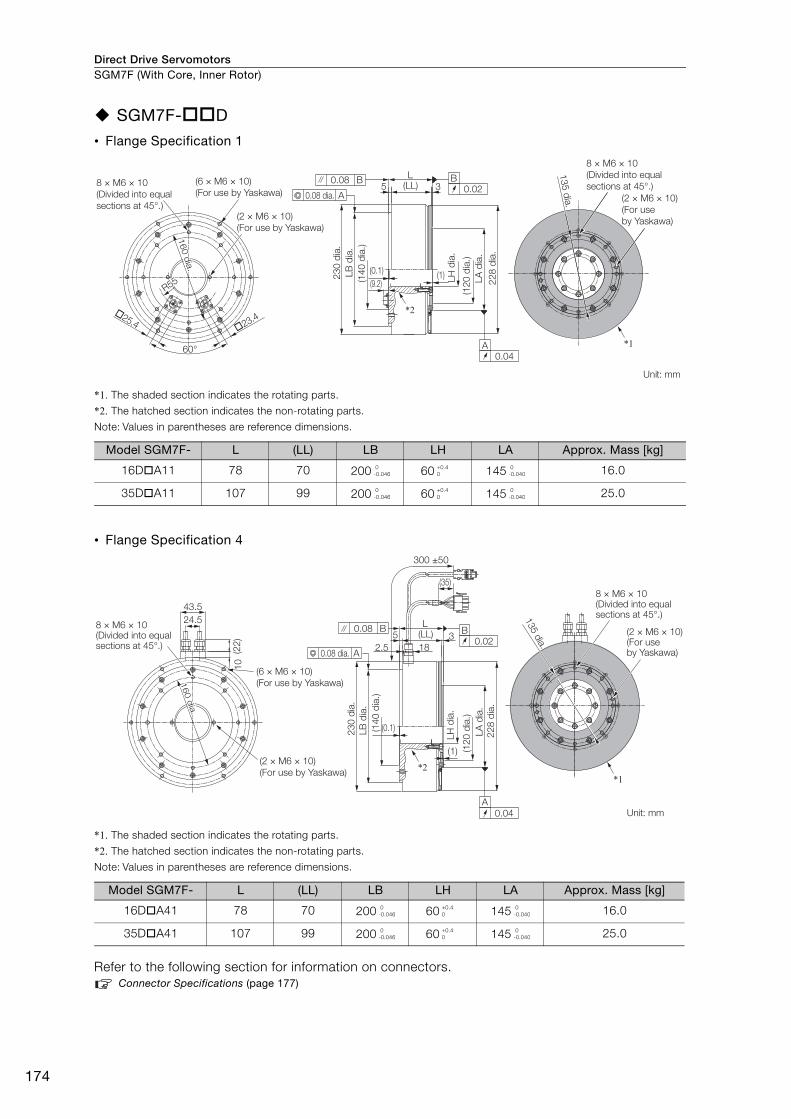
Direct Drive ServomotorsSGM7F (With Core, Inner Rotor)
174
SGM7F-D
• Flange Specification 1
*1. The shaded section indicates the rotating parts.
*2. The hatched section indicates the non-rotating parts.
Note: Values in parentheses are reference dimensions.
• Flange Specification 4
*1. The shaded section indicates the rotating parts.
*2. The hatched section indicates the non-rotating parts.
Note: Values in parentheses are reference dimensions.
Refer to the following section for information on connectors.Connector Specifications (page 177)
Model SGM7F- L (LL) LB LH LA Approx. Mass [kg]
16DA11 78 70 200 60 145 16.0
35DA11 107 99 200 60 145 25.0
Model SGM7F- L (LL) LB LH LA Approx. Mass [kg]
16DA41 78 70 200 60 145 16.0
35DA41 107 99 200 60 145 25.0
Unit: mm
60°
�25.4 �23.4
8 × M6 × 10
(Divided into equal
sections at 45°.)(2 × M6 × 10)
(For use by Yaskawa)
(6 × M6 × 10)
(For use by Yaskawa)
R55R55
160 d
ia.
160 d
ia.
160 d
ia.
R55
L(LL)5 3
B
0.02
A
0.04
23
0 d
ia.
LB
dia
.
(14
0 d
ia.)
(0.1)
(9.2) 22
8 d
ia.
LA
dia
.
(12
0 d
ia.)
LH
dia
.
(1)
0.08 B
A0.08 dia.
*2
8 × M6 × 10
(Divided into equal
sections at 45°.)
(2 × M6 × 10)
(For use
by Yaskawa)
*1
135 d
ia.
0-0.046
+0.40
0-0.040
0-0.046
+0.40
0-0.040
Unit: mm
24.5
43.5
(6 × M6 × 10)
(For use by Yaskawa)
(2 × M6 × 10)
(For use by Yaskawa)
8 × M6 × 10(Divided into equal sections at 45°.)
(22
)1
0
(1)
22
8 d
ia.
LA
dia
.
(12
0 d
ia.)
LH
dia
.
0.08 B
A0.08 dia.
(0.1)
23
0 d
ia.
LB
dia
.
(14
0 d
ia.)
300 ±50
(35)
(LL)L
3
18
5
2.5
A
0.04
B
0.02
*2
8 × M6 × 10(Divided into equal sections at 45°.)
(2 × M6 × 10)(For use by Yaskawa)
135 d
ia.
*1
160 d
ia.
160 d
ia.
160 d
ia.
0-0.046
+0.40
0-0.040
0-0.046
+0.40
0-0.040
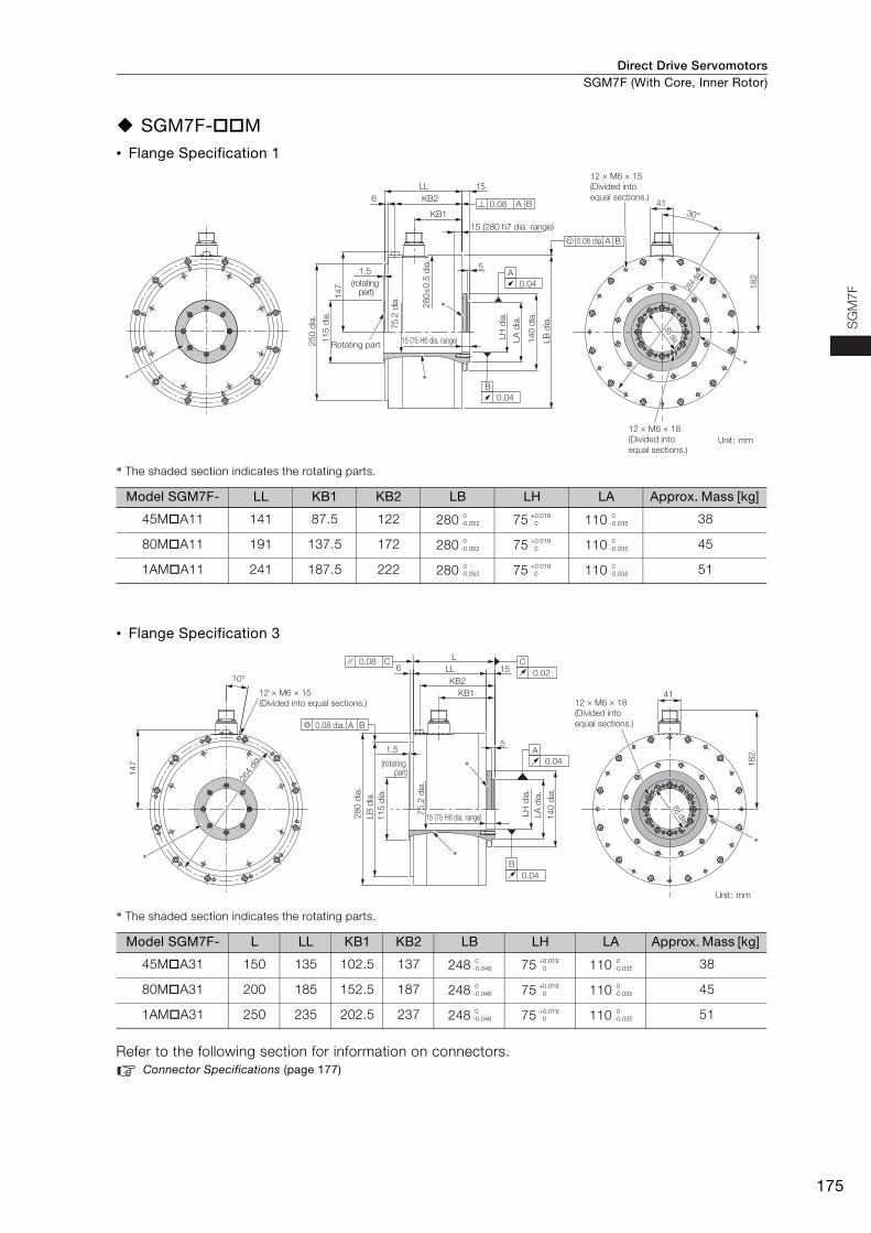
Direct Drive Servomotors SGM7F (With Core, Inner Rotor)
175
SG
M7
F
SGM7F-M• Flange Specification 1
* The shaded section indicates the rotating parts.
• Flange Specification 3
* The shaded section indicates the rotating parts.
Refer to the following section for information on connectors. Connector Specifications (page 177)
Model SGM7F- LL KB1 KB2 LB LH LA Approx. Mass [kg]
45MA11 141 87.5 122 280 75 110 38
80MA11 191 137.5 172 280 75 110 45
1AMA11 241 187.5 222 280 75 110 51
Model SGM7F- L LL KB1 KB2 LB LH LA Approx. Mass [kg]
45MA31 150 135 102.5 137 248 75 110 38
80MA31 200 185 152.5 187 248 75 110 45
1AMA31 250 235 202.5 237 248 75 110 51
A
15
14
7 18
2
264
dia.
41
0.04
0.04
B
0.08 dia.
15 (280 h7 dia. range)
15 (75 H6 dia. range)
A B
0.08 A B
12 × M6 × 15
(Divided into
equal sections.)
30°
KB2
KB1
LL
6
51.5
Rotating part
*
*
*
LH
dia
.
75.2
dia
.
25
0 d
ia.
28
0±
0.5
dia
.
11
5 d
ia.
LA
dia
.
14
0 d
ia.
LB
dia
.
(rotating part)
12 × M6 × 18
(Divided into
equal sections.)Unit: mm
88 dia.88 dia.88 dia.
*
0-0.052
+0.019 0
0-0.035
0-0.052
+0.019 0
0-0.035
0-0.052
+0.019 0
0-0.035
51
82
15LL6
KB2
KB1
L
41
1.5
0.08 C
*
*
A B0.08 dia.
LH
dia
.
11
5 d
ia.
75
.2 d
ia.
28
0 d
ia.
LA
dia
.
LB
dia
.
14
0 d
ia.
15 (75 H6 dia. range)
88 dia.
88 dia.
10°
14
7
12 × M6 × 15
(Divided into equal sections.)
264
dia
.
C
0.02
A
0.04
B
0.04
(rotating part)
*
Unit: mm
12 × M6 × 18
(Divided into
equal sections.)
88 dia.
*
0-0.046
+0.019 0
0-0.035
0-0.046
+0.019 0
0-0.035
0-0.046
+0.019 0
0-0.035
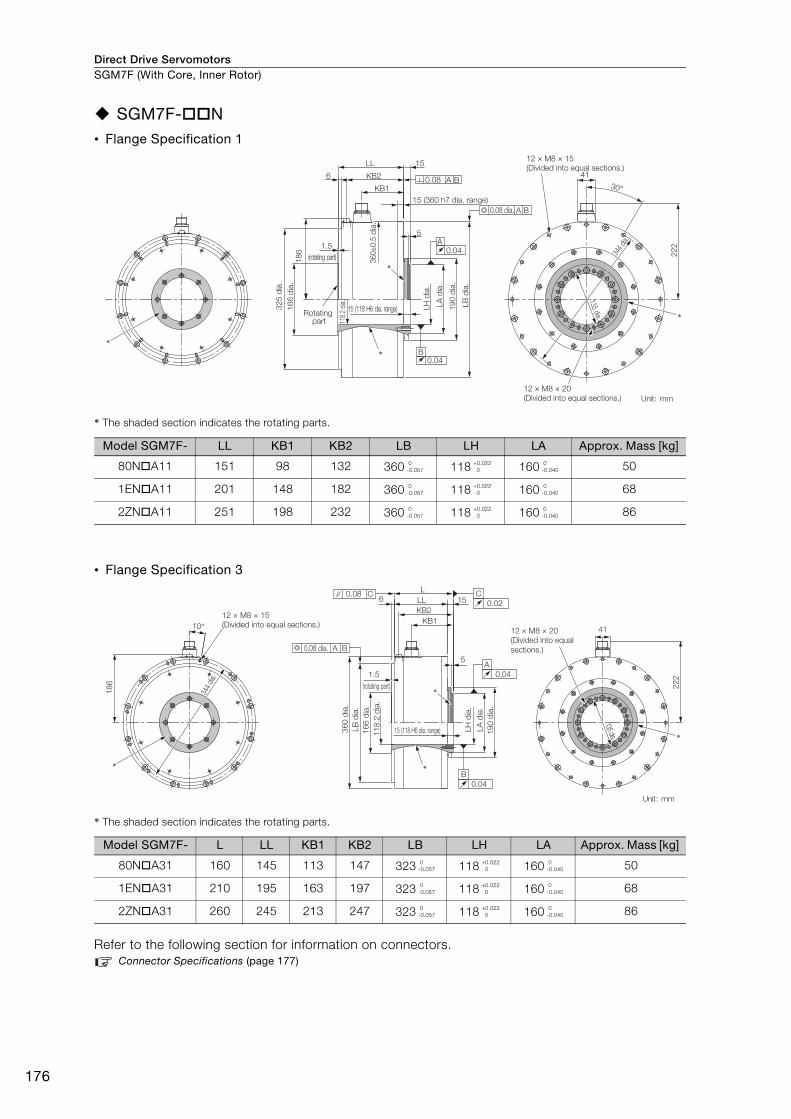
Direct Drive ServomotorsSGM7F (With Core, Inner Rotor)
176
SGM7F-N• Flange Specification 1
* The shaded section indicates the rotating parts.
• Flange Specification 3
* The shaded section indicates the rotating parts.
Refer to the following section for information on connectors. Connector Specifications (page 177)
Model SGM7F- LL KB1 KB2 LB LH LA Approx. Mass [kg]
80NA11 151 98 132 360 118 160 50
1ENA11 201 148 182 360 118 160 68
2ZNA11 251 198 232 360 118 160 86
Model SGM7F- L LL KB1 KB2 LB LH LA Approx. Mass [kg]
80NA31 160 145 113 147 323 118 160 50
1ENA31 210 195 163 197 323 118 160 68
2ZNA31 260 245 213 247 323 118 160 86
15 (360 h7 dia. range)
A
30°
344
dia.
15
LB
dia
.
16
6 d
ia.
12 × M8 × 20
(Divided into equal sections.)
15 (118 H6 dia. range)
0.04
0.04
LH
dia
.
B
19
0 d
ia.
LA
dia
.
0.08 dia. A B
0.08 A B
22
2
41
18
6
KB2
KB1
118.
2 di
a.
5
360±
0.5
dia
.
LL
32
5 d
ia.
6
12 × M8 × 15
(Divided into equal sections.)
1.5
Rotating part
(rotating part)
*
*
*
Unit: mm
135 dia.
*
0-0.057
+0.022 0
0-0.040
0-0.057
+0.022 0
0-0.040
0-0.057
+0.022 0
0-0.040
10°
22
2
41
1.5
5
LL 156
KB2
KB1
L
18
6
12 × M8 × 15
(Divided into equal sections.)
344
dia.
*
*
0.08 C C
0.02
B
0.04
A
0.04
A B0.08 dia.
11
8.2
dia
.
16
6 d
ia.
LB
dia
.
36
0 d
ia.
LH
dia
.
19
0 d
ia.
LA
dia
.
15 (118 H6 dia. range)
135 dia.
12 × M8 × 20
(Divided into equal
sections.)
(rotating part)
*
Unit: mm
*
0-0.057
+0.022 0
0-0.040
0-0.057
+0.022 0
0-0.040
0-0.057
+0.022 0
0-0.040
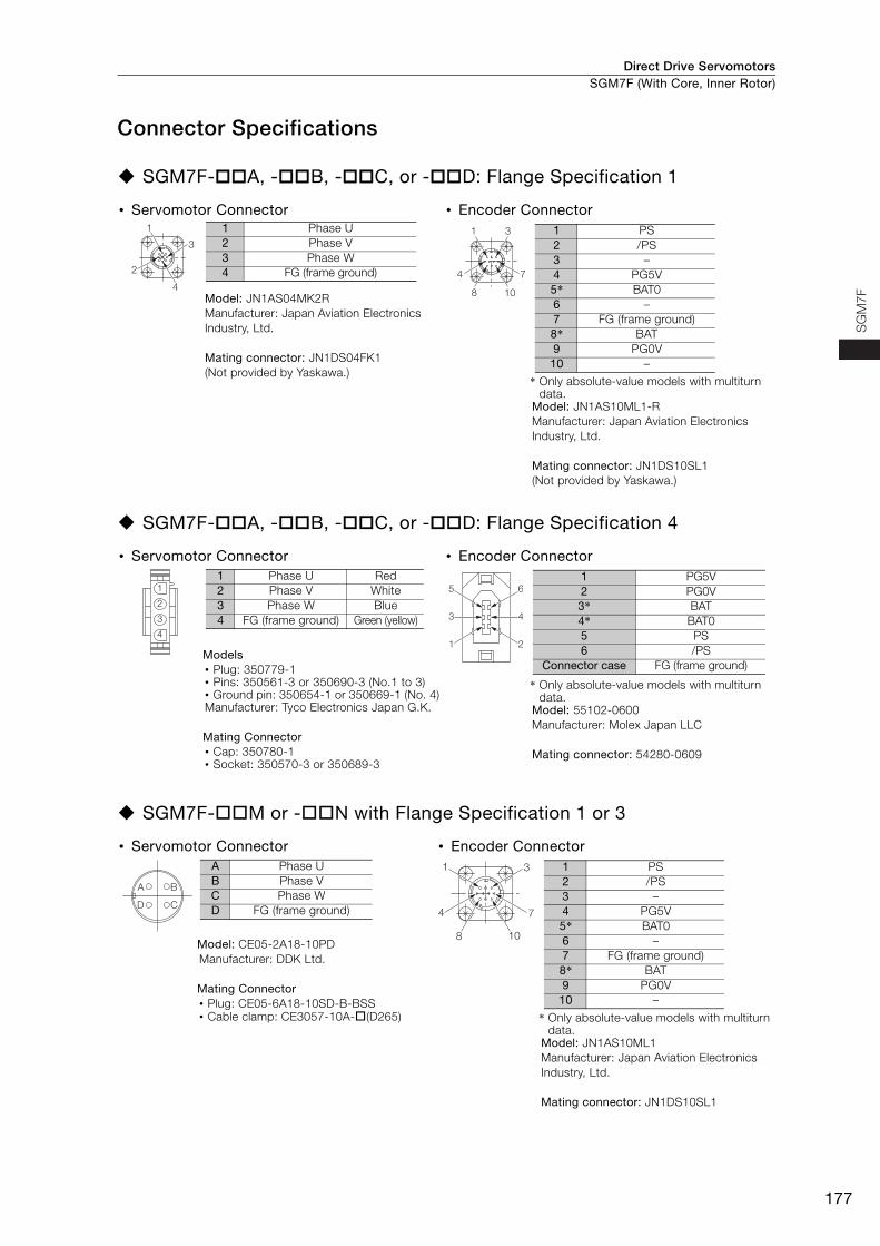
Direct Drive Servomotors SGM7F (With Core, Inner Rotor)
177
SG
M7
F
Connector Specifications
SGM7F-A, -B, -C, or -D: Flange Specification 1
SGM7F-A, -B, -C, or -D: Flange Specification 4
SGM7F-M or -N with Flange Specification 1 or 3
• Servomotor Connector • Encoder Connector
Model: JN1AS04MK2RManufacturer: Japan Aviation Electronics Industry, Ltd.
Mating connector: JN1DS04FK1(Not provided by Yaskawa.)
* Only absolute-value models with multiturn data.
Model: JN1AS10ML1-R Manufacturer: Japan Aviation Electronics Industry, Ltd.
Mating connector: JN1DS10SL1 (Not provided by Yaskawa.)
• Servomotor Connector • Encoder Connector
Models • Plug: 350779-1 • Pins: 350561-3 or 350690-3 (No.1 to 3) • Ground pin: 350654-1 or 350669-1 (No. 4) Manufacturer: Tyco Electronics Japan G.K.
Mating Connector • Cap: 350780-1 • Socket: 350570-3 or 350689-3
* Only absolute-value models with multiturn data.
Model: 55102-0600Manufacturer: Molex Japan LLC
Mating connector: 54280-0609
• Servomotor Connector • Encoder Connector
Model: CE05-2A18-10PDManufacturer: DDK Ltd.
Mating Connector • Plug: CE05-6A18-10SD-B-BSS• Cable clamp: CE3057-10A-(D265) * Only absolute-value models with multiturn
data.Model: JN1AS10ML1Manufacturer: Japan Aviation Electronics Industry, Ltd.
Mating connector: JN1DS10SL1
1
3
2
4
1 Phase U2 Phase V3 Phase W4 FG (frame ground)
1 3
4 7
8 10
1 PS2 /PS3 –4 PG5V5* BAT06 –7 FG (frame ground)8* BAT9 PG0V
10 –
1
2
3
4
1 Phase U Red2 Phase V White3 Phase W Blue4 FG (frame ground) Green (yellow) 4
2
6
3
1
5
1 PG5V2 PG0V3* BAT4* BAT05 PS6 /PS
Connector case FG (frame ground)
BA
CD
A Phase UB Phase VC Phase WD FG (frame ground)
1 3
4 7
8 10
1 PS2 /PS3 –4 PG5V5* BAT06 –7 FG (frame ground)8* BAT9 PG0V
10 –
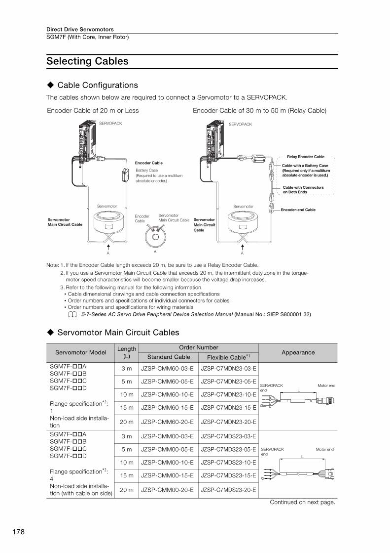
Direct Drive ServomotorsSGM7F (With Core, Inner Rotor)
178
Selecting Cables
Cable ConfigurationsThe cables shown below are required to connect a Servomotor to a SERVOPACK.
Note: 1. If the Encoder Cable length exceeds 20 m, be sure to use a Relay Encoder Cable.
2. If you use a Servomotor Main Circuit Cable that exceeds 20 m, the intermittent duty zone in the torque-motor speed characteristics will become smaller because the voltage drop increases.
3. Refer to the following manual for the following information.• Cable dimensional drawings and cable connection specifications• Order numbers and specifications of individual connectors for cables• Order numbers and specifications for wiring materials
Σ-7-Series AC Servo Drive Peripheral Device Selection Manual (Manual No.: SIEP S800001 32)
Servomotor Main Circuit Cables
Encoder Cable of 20 m or Less Encoder Cable of 30 m to 50 m (Relay Cable)
Servomotor ModelLength
(L)
Order NumberAppearance
Standard Cable Flexible Cable*1
SGM7F-ASGM7F-BSGM7F-CSGM7F-D
Flange specification*2: 1Non-load side installa-tion
3 m JZSP-CMM60-03-E JZSP-C7MDN23-03-E
5 m JZSP-CMM60-05-E JZSP-C7MDN23-05-E
10 m JZSP-CMM60-10-E JZSP-C7MDN23-10-E
15 m JZSP-CMM60-15-E JZSP-C7MDN23-15-E
20 m JZSP-CMM60-20-E JZSP-C7MDN23-20-E
SGM7F-ASGM7F-BSGM7F-CSGM7F-D
Flange specification*2: 4Non-load side installa-tion (with cable on side)
3 m JZSP-CMM00-03-E JZSP-C7MDS23-03-E
5 m JZSP-CMM00-05-E JZSP-C7MDS23-05-E
10 m JZSP-CMM00-10-E JZSP-C7MDS23-10-E
15 m JZSP-CMM00-15-E JZSP-C7MDS23-15-E
20 m JZSP-CMM00-20-E JZSP-C7MDS23-20-E
Continued on next page.
SERVOPACK
Encoder Cable
Encoder
Cable
Servomotor
Servomotor Main Circuit Cable
Servomotor
Main Circuit Cable
A A
Battery Case
(Required to use a multiturn
absolute encoder.)
SERVOPACK
Cable with a Battery Case(Required only if a multiturn absolute encoder is used.)
Cable with Connectors on Both Ends
Encoder-end CableServomotor
Servomotor Main Circuit Cable
A
Relay Encoder Cable
L
SERVOPACK
end
Motor end
L
SERVOPACK
end
Motor end
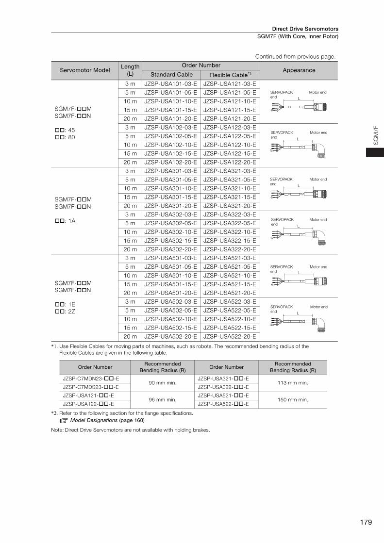
Direct Drive Servomotors SGM7F (With Core, Inner Rotor)
179
SG
M7
F
*1. Use Flexible Cables for moving parts of machines, such as robots. The recommended bending radius of the Flexible Cables are given in the following table.
*2. Refer to the following section for the flange specifications.Model Designations (page 160)
Note: Direct Drive Servomotors are not available with holding brakes.
SGM7F-MSGM7F-N
: 45: 80
3 m JZSP-USA101-03-E JZSP-USA121-03-E
5 m JZSP-USA101-05-E JZSP-USA121-05-E
10 m JZSP-USA101-10-E JZSP-USA121-10-E
15 m JZSP-USA101-15-E JZSP-USA121-15-E
20 m JZSP-USA101-20-E JZSP-USA121-20-E
3 m JZSP-USA102-03-E JZSP-USA122-03-E
5 m JZSP-USA102-05-E JZSP-USA122-05-E
10 m JZSP-USA102-10-E JZSP-USA122-10-E
15 m JZSP-USA102-15-E JZSP-USA122-15-E
20 m JZSP-USA102-20-E JZSP-USA122-20-E
SGM7F-MSGM7F-N
: 1A
3 m JZSP-USA301-03-E JZSP-USA321-03-E
5 m JZSP-USA301-05-E JZSP-USA321-05-E
10 m JZSP-USA301-10-E JZSP-USA321-10-E
15 m JZSP-USA301-15-E JZSP-USA321-15-E
20 m JZSP-USA301-20-E JZSP-USA321-20-E
3 m JZSP-USA302-03-E JZSP-USA322-03-E
5 m JZSP-USA302-05-E JZSP-USA322-05-E
10 m JZSP-USA302-10-E JZSP-USA322-10-E
15 m JZSP-USA302-15-E JZSP-USA322-15-E
20 m JZSP-USA302-20-E JZSP-USA322-20-E
SGM7F-MSGM7F-N
: 1E: 2Z
3 m JZSP-USA501-03-E JZSP-USA521-03-E
5 m JZSP-USA501-05-E JZSP-USA521-05-E
10 m JZSP-USA501-10-E JZSP-USA521-10-E
15 m JZSP-USA501-15-E JZSP-USA521-15-E
20 m JZSP-USA501-20-E JZSP-USA521-20-E
3 m JZSP-USA502-03-E JZSP-USA522-03-E
5 m JZSP-USA502-05-E JZSP-USA522-05-E
10 m JZSP-USA502-10-E JZSP-USA522-10-E
15 m JZSP-USA502-15-E JZSP-USA522-15-E
20 m JZSP-USA502-20-E JZSP-USA522-20-E
Order NumberRecommended
Bending Radius (R)Order Number
Recommended Bending Radius (R)
JZSP-C7MDN23--E90 mm min.
JZSP-USA321--E113 mm min.
JZSP-C7MDS23--E JZSP-USA322--E
JZSP-USA121--E96 mm min.
JZSP-USA521--E150 mm min.
JZSP-USA122--E JZSP-USA522--E
Continued from previous page.
Servomotor ModelLength
(L)
Order NumberAppearance
Standard Cable Flexible Cable*1
L
SERVOPACK
end
Motor end
L
SERVOPACK
end
Motor end
L
SERVOPACK
end
Motor end
L
SERVOPACK
end
Motor end
L
SERVOPACK
end
Motor end
L
SERVOPACK
end
Motor end
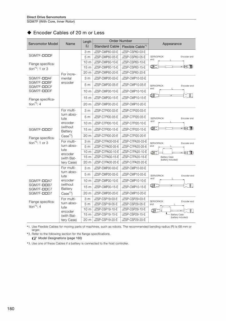
Direct Drive ServomotorsSGM7F (With Core, Inner Rotor)
180
Encoder Cables of 20 m or Less
*1. Use Flexible Cables for moving parts of machines, such as robots. The recommended bending radius (R) is 68 mm or larger.
*2. Refer to the following section for the flange specifications.Model Designations (page 160)
*3. Use one of these Cables if a battery is connected to the host controller.
Servomotor Model NameLength
(L)
Order NumberAppearance
Standard Cable Flexible Cable*1
SGM7F-F
Flange specifica-tion*2: 1 or 3
For incre-mental encoder
3 m JZSP-CMP60-03-E JZSP-CSP60-03-E
5 m JZSP-CMP60-05-E JZSP-CSP60-05-E
10 m JZSP-CMP60-10-E JZSP-CSP60-10-E
15 m JZSP-CMP60-15-E JZSP-CSP60-15-E
20 m JZSP-CMP60-20-E JZSP-CSP60-20-E
SGM7F-AFSGM7F-BFSGM7F-CFSGM7F-DF
Flange specifica-tion*2: 4
3 m JZSP-CMP00-03-E JZSP-CMP10-03-E
5 m JZSP-CMP00-05-E JZSP-CMP10-05-E
10 m JZSP-CMP00-10-E JZSP-CMP10-10-E
15 m JZSP-CMP00-15-E JZSP-CMP10-15-E
20 m JZSP-CMP00-20-E JZSP-CMP10-20-E
SGM7F-7
Flange specifica-tion*2: 1 or 3
For multi-turn abso-lute encoder (without Battery Case*3)
3 m JZSP-C7PI00-03-E JZSP-C7PI20-03-E
5 m JZSP-C7PI00-05-E JZSP-C7PI20-05-E
10 m JZSP-C7PI00-10-E JZSP-C7PI20-10-E
15 m JZSP-C7PI00-15-E JZSP-C7PI20-15-E
20 m JZSP-C7PI00-20-E JZSP-C7PI20-20-E
For multi-turn abso-lute encoder(with Bat-tery Case)
3 m JZSP-C7PA00-03-E JZSP-C7PA20-03-E
5 m JZSP-C7PA00-05-E JZSP-C7PA20-05-E
10 m JZSP-C7PA00-10-E JZSP-C7PA20-10-E
15 m JZSP-C7PA00-15-E JZSP-C7PA20-15-E
20 m JZSP-C7PA00-20-E JZSP-C7PA20-20-E
SGM7F-A7SGM7F-B7SGM7F-C7SGM7F-D7
Flange specifica-tion*2: 4
For multi-turn abso-lute encoder (without Battery Case*3)
3 m JZSP-CMP00-03-E JZSP-CMP10-03-E
5 m JZSP-CMP00-05-E JZSP-CMP10-05-E
10 m JZSP-CMP00-10-E JZSP-CMP10-10-E
15 m JZSP-CMP00-15-E JZSP-CMP10-15-E
20 m JZSP-CMP00-20-E JZSP-CMP10-20-E
For multi-turn abso-lute encoder(with Bat-tery Case)
3 m JZSP-CSP19-03-E JZSP-CSP29-03-E
5 m JZSP-CSP19-05-E JZSP-CSP29-05-E
10 m JZSP-CSP19-10-E JZSP-CSP29-10-E
15 m JZSP-CSP19-15-E JZSP-CSP29-15-E
20 m JZSP-CSP19-20-E JZSP-CSP29-20-E
L
SERVOPACK
end
Encoder end
L
SERVOPACK
end
Encoder end
L
SERVOPACK
end
Encoder end
SERVOPACK
end
Encoder end
Battery Case
(battery included)
L
L
SERVOPACK
end
Encoder end
SERVOPACK
end
Encoder end
Battery Case
(battery included)
L
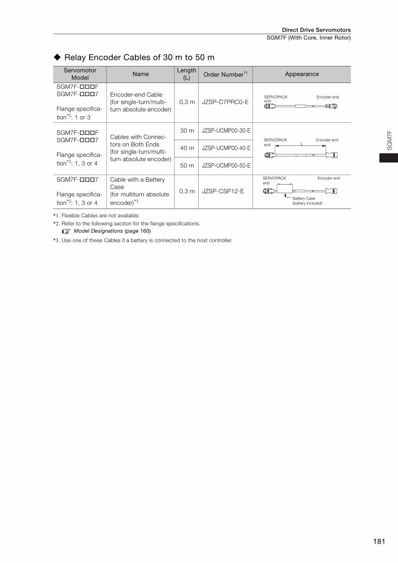
Direct Drive Servomotors SGM7F (With Core, Inner Rotor)
181
SG
M7
F
Relay Encoder Cables of 30 m to 50 m
*1. Flexible Cables are not available.
*2. Refer to the following section for the flange specifications.Model Designations (page 160)
*3. Use one of these Cables if a battery is connected to the host controller.
Servomotor Model
NameLength
(L) Order Number*1 Appearance
SGM7F-FSGM7F-7
Flange specifica-tion*2: 1 or 3
Encoder-end Cable (for single-turn/multi-turn absolute encoder)
0.3 m JZSP-C7PRC0-E
SGM7F-FSGM7F-7
Flange specifica-tion*2: 1, 3 or 4
Cables with Connec-tors on Both Ends (for single-turn/multi-turn absolute encoder)
30 m JZSP-UCMP00-30-E
40 m JZSP-UCMP00-40-E
50 m JZSP-UCMP00-50-E
SGM7F-7
Flange specifica-tion*2: 1, 3 or 4
Cable with a Battery Case(for multiturn absolute encoder)*3
0.3 m JZSP-CSP12-E
SERVOPACK end
Encoder end
LSERVOPACK
end
Encoder end
SERVOPACK
end
Encoder end
Battery Case
(battery included)
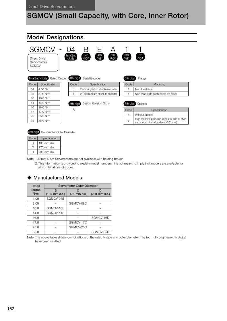
Direct Drive Servomotors
182
SGMCV (Small Capacity, with Core, Inner Rotor)
Model Designations
Note: 1. Direct Drive Servomotors are not available with holding brakes.
2. This information is provided to explain model numbers. It is not meant to imply that models are available for all combinations of codes.
Manufactured Models
Note: The above table shows combinations of the rated torque and outer diameter. The fourth through seventh digits have been omitted.
Rated Torque
Nm
Servomotor Outer Diameter
B (135-mm dia.)
C (175-mm dia.)
D (230-mm dia.)
4.00 SGMCV-04B – –
8.00 – SGMCV-08C –
10.0 SGMCV-10B – –
14.0 SGMCV-14B – –
16.0 – – SGMCV-16D
17.0 – SGMCV-17C –
25.0 – SGMCV-25C –
35.0 – – SGMCV-35D
B
D
E
I
1
5
1
4
4th digit 6th digit
3rd digit
7th digit
Mounting
Non-load side
Non-load side (with cable on side)
Options
Without options
High machine precision (runout at end of shaft
and runout of shaft surface: 0.01 mm)
22-bit single-turn absolute encoder
22-bit multiturn absolute encoder
A
5th digit Design Revision Order
Servomotor Outer Diameter
135-mm dia.
230-mm dia.
C 175-mm dia.
Serial Encoder Flange
SGMCV - 04 B E A 1 11st+2nd
digits
1st+2nd digits Rated Output
Code Specification
3rd digit
4th digit
5th digit
6th digit
7th digitDirect Drive
Servomotors:
SGMCV
Code Code
Code
Code
Specification
Specification
Specification
04 4.00 Nm
08 8.00 Nm
10 10.0 Nm
14 14.0 Nm
17 17.0 Nm
25 25.0 Nm
16 16.0 Nm
35 35.0 Nm
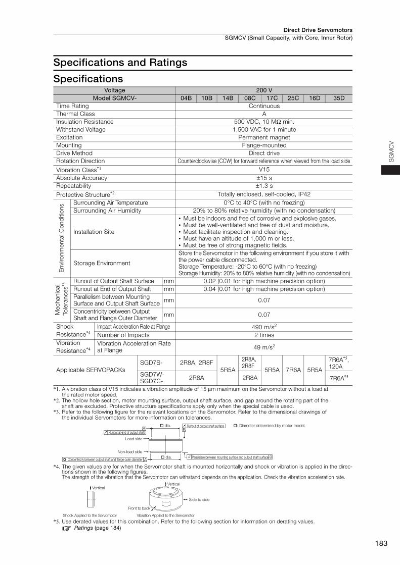
Direct Drive Servomotors SGMCV (Small Capacity, with Core, Inner Rotor)
183
SG
MC
V
Specifications and Ratings
Specifications
*1. A vibration class of V15 indicates a vibration amplitude of 15 μm maximum on the Servomotor without a load at the rated motor speed.
*2. The hollow hole section, motor mounting surface, output shaft surface, and gap around the rotating part of the shaft are excluded. Protective structure specifications apply only when the special cable is used.
*3. Refer to the following figure for the relevant locations on the Servomotor. Refer to the dimensional drawings of the individual Servomotors for more information on tolerances.
*4. The given values are for when the Servomotor shaft is mounted horizontally and shock or vibration is applied in the direc-tions shown in the following figures.The strength of the vibration that the Servomotor can withstand depends on the application. Check the vibration acceleration rate.
*5. Use derated values for this combination. Refer to the following section for information on derating values.Ratings (page 184)
Voltage 200 VModel SGMCV- 04B 10B 14B 08C 17C 25C 16D 35D
Time Rating Continuous Thermal Class AInsulation Resistance 500 VDC, 10 MΩ min. Withstand Voltage 1,500 VAC for 1 minute Excitation Permanent magnet Mounting Flange-mounted Drive Method Direct drive Rotation Direction Counterclockwise (CCW) for forward reference when viewed from the load side
Vibration Class*1 V15Absolute Accuracy ±15 s Repeatability ±1.3 s
Protective Structure*2 Totally enclosed, self-cooled, IP42
Env
ironm
enta
l Con
diti
ons Surrounding Air Temperature 0°C to 40°C (with no freezing)
Surrounding Air Humidity 20% to 80% relative humidity (with no condensation)
Installation Site
• Must be indoors and free of corrosive and explosive gases. • Must be well-ventilated and free of dust and moisture. • Must facilitate inspection and cleaning. • Must have an altitude of 1,000 m or less.• Must be free of strong magnetic fields.
Storage Environment
Store the Servomotor in the following environment if you store it with the power cable disconnected. Storage Temperature: -20°C to 60°C (with no freezing)Storage Humidity: 20% to 80% relative humidity (with no condensation)
Mec
hani
cal
Tol
eran
ces*3
Runout of Output Shaft Surface mm 0.02 (0.01 for high machine precision option) Runout at End of Output Shaft mm 0.04 (0.01 for high machine precision option) Parallelism between Mounting Surface and Output Shaft Surface mm 0.07
Concentricity between Output Shaft and Flange Outer Diameter mm 0.07
Shock Resistance*4
Impact Acceleration Rate at Flange 490 m/s2
Number of Impacts 2 times Vibration Resistance*4
Vibration Acceleration Rate at Flange 49 m/s2
Applicable SERVOPACKsSGD7S- 2R8A, 2R8F
5R5A
2R8A, 2R8F
5R5A 7R6A 5R5A
7R6A*5, 120A
SGD7W-SGD7C- 2R8A 2R8A 7R6A*5
A
A B
B
Runout at end of output shaft
dia.
Load side
Non-load side
Concentricity between output shaft and flange outer diameter dia. Parallelism between mounting surface and output shaft surface
Runout of output shaft surface : Diameter determined by motor model.
Side to side
Front to back
Vertical
Shock Applied to the Servomotor Vibration Applied to the Servomotor
Vertical
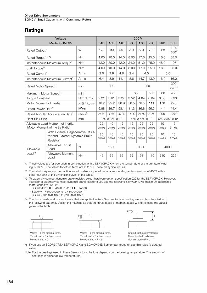
Direct Drive ServomotorsSGMCV (Small Capacity, with Core, Inner Rotor)
184
Ratings
*1. These values are for operation in combination with a SERVOPACK when the temperature of the armature wind-ing is 100°C. The values for other items are at 20°C. These are typical values.
*2. The rated torques are the continuous allowable torque values at a surrounding air temperature of 40°C with a steel heat sink of the dimensions given in the table.
*3. To externally connect dynamic brake resistor, select hardware option specification 020 for the SERVOPACK. However, you cannot externally connect dynamic brake resistor if you use the following SERVOPACKs (maximum applicable motor capacity: 400 W).• SGD7S-R70A020 to -2R8A020• SGD7W-1R6A20A020 to -2R8A20A020• SGD7C-1R6AMAA020 to -2R8AMAA020
*4. The thrust loads and moment loads that are applied while a Servomotor is operating are roughly classified into the following patterns. Design the machine so that the thrust loads or moment loads will not exceed the values given in the table.
*5. If you use an SGD7S-7R6A SERVOPACK and SGMCV-35D Servomotor together, use this value (a derated value).
Note: For the bearings used in these Servomotors, the loss depends on the bearing temperature. The amount of heat loss is higher at low temperatures.
Voltage 200 V
Model SGMCV- 04B 10B 14B 08C 17C 25C 16D 35D
Rated Output*1 W 126 314 440 251 534 785 5031100
1000*5
Rated Torque*1, *2 Nm 4.00 10.0 14.0 8.00 17.0 25.0 16.0 35.0
Instantaneous Maximum Torque*1 Nm 12.0 30.0 42.0 24.0 51.0 75.0 48.0 105
Stall Torque*1 Nm 4.00 10.0 14.0 8.00 17.0 25.0 16.0 35.0
Rated Current*1 Arms 2.0 2.8 4.6 2.4 4.5 5.0
Instantaneous Maximum Current*1 Arms 6.4 8.9 14.1 8.6 14.7 13.9 16.9 16.0
Rated Motor Speed*1 min-1 300 300300
270*5
Maximum Motor Speed*1 min-1 600 600 500 600 400
Torque Constant Nm/Arms 2.21 3.81 3.27 3.52 4.04 6.04 3.35 7.33
Motor Moment of Inertia ×10-4 kgm2 16.2 25.2 36.9 56.5 78.5 111 178 276
Rated Power Rate*1 kW/s 9.88 39.7 53.1 11.3 36.8 56.3 14.4 44.4
Rated Angular Acceleration Rate*1 rad/s2 2470 3970 3790 1420 2170 2250 899 1270
Heat Sink Size mm 350 × 350 × 12 450 × 450 × 12 550 × 550 × 12
Allowable Load Moment of Inertia (Motor Moment of Inertia Ratio)
25 times
40 times
45 times
15 times
25 times
25 times
10 times
15 times
With External Regenerative Resis-tor and External Dynamic Brake Resistor*3
25 times
40 times
45 times
15 times
25 times
25 times
10 times
15 times
Allowable Load*4
Allowable Thrust Load
N 1500 3300 4000
Allowable Moment Load
Nm 45 55 65 92 98 110 210 225
F
F
LF
L
Where F is the external force,
Thrust load = F + Load mass
Moment load = 0
Where F is the external force,
Thrust load = F + Load mass
Moment load = F × L
Where F is the external force,
Thrust load = Load mass
Moment load = F × L
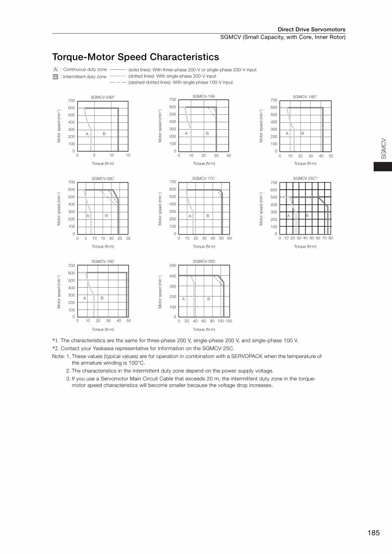
Direct Drive Servomotors SGMCV (Small Capacity, with Core, Inner Rotor)
185
SG
MC
V
Torque-Motor Speed Characteristics
*1. The characteristics are the same for three-phase 200 V, single-phase 200 V, and single-phase 100 V.
*2. Contact your Yaskawa representative for information on the SGMCV-25C.
Note: 1. These values (typical values) are for operation in combination with a SERVOPACK when the temperature of the armature winding is 100°C.
2. The characteristics in the intermittent duty zone depend on the power supply voltage.
3. If you use a Servomotor Main Circuit Cable that exceeds 20 m, the intermittent duty zone in the torque-motor speed characteristics will become smaller because the voltage drop increases.
SGMCV-08C
0 5 10 15 20 25 30
0
100
200
300
400
500
600
700
A B
SGMCV-17C
0 10 20 30 40 50 600
100
200
300
400
500
600
700
A B
SGMCV-04B*1
0
100
200
300
400
500
600
700
0 5 10 15
A B
SGMCV-25C*2
0 10 20 30 40 50 60 70 800
100
200
300
400
500
600
700
A B
SGMCV-10B
0 10 20 30 400
100
200
300
400
500
600
700
A B
SGMCV-14B*1
0 10 20 30 40 50
0
100
200
300
400
500
600
700
A B
SGMCV-16D
0 10 20 30 40 500
100
200
300
400
500
600
700SGMCV-35D
A B
0 20 40 60 80 100 1200
100
200
300
400
500
A B
A :
B :
(dashed-dotted lines): With single-phase 100-V input
(solid lines): With three-phase 200-V or single-phase 230-V input
(dotted lines): With single-phase 200-V inputIntermittent duty zone
Continuous duty zone
Torque (N�m)
Mo
tor
sp
eed
(m
in-1)
Torque (N�m)M
oto
r sp
eed
(m
in-1)
Torque (N�m)
Mo
tor
sp
eed
(m
in-1)
Torque (N�m)
Mo
tor
sp
eed
(m
in-1)
Torque (N�m)
Mo
tor
sp
eed
(m
in-1)
Torque (N�m)
Mo
tor
sp
eed
(m
in-1)
Torque (N�m)
Mo
tor
sp
eed
(m
in-1)
Torque (N�m)
Mo
tor
sp
eed
(m
in-1)
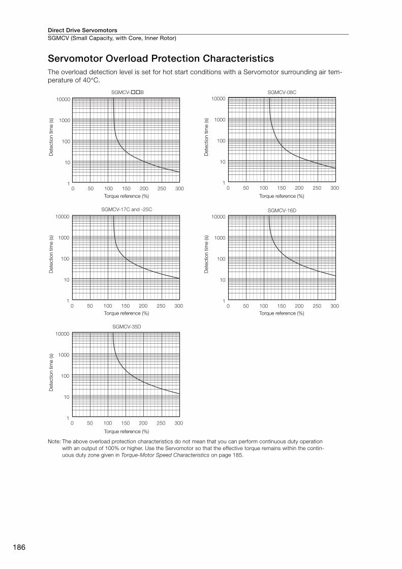
Direct Drive ServomotorsSGMCV (Small Capacity, with Core, Inner Rotor)
186
Servomotor Overload Protection Characteristics The overload detection level is set for hot start conditions with a Servomotor surrounding air tem-perature of 40°C.
Note: The above overload protection characteristics do not mean that you can perform continuous duty operation with an output of 100% or higher. Use the Servomotor so that the effective torque remains within the contin-uous duty zone given in Torque-Motor Speed Characteristics on page 185.
10000
1000
100
10
1
SGMCV-��B SGMCV-08C
0 50 100 150 200 250 300
10000
1000
100
10
1
SGMCV-17C and -25C
0 50 100 150 200 250 300
10000
1000
100
10
1
SGMCV-35D
0 50 100 150 200 250 300
10000
1000
100
10
10 50 100 150 200 250 300
SGMCV-16D
10000
1000
100
10
10 50 100 150 200 250 300
Dete
ctio
n t
ime (s)
Torque reference (%)
Dete
ctio
n t
ime (s)
Torque reference (%)
Dete
ctio
n t
ime (s)
Torque reference (%)
Dete
ctio
n t
ime (s)
Torque reference (%)
Dete
ctio
n t
ime (s)
Torque reference (%)
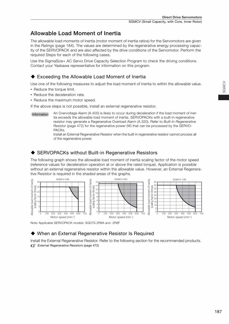
Direct Drive Servomotors SGMCV (Small Capacity, with Core, Inner Rotor)
187
SG
MC
V
Allowable Load Moment of InertiaThe allowable load moments of inertia (motor moment of inertia ratios) for the Servomotors are given in the Ratings (page 184). The values are determined by the regenerative energy processing capac-ity of the SERVOPACK and are also affected by the drive conditions of the Servomotor. Perform the required Steps for each of the following cases.
Use the SigmaSize+ AC Servo Drive Capacity Selection Program to check the driving conditions. Contact your Yaskawa representative for information on this program.
Exceeding the Allowable Load Moment of InertiaUse one of the following measures to adjust the load moment of inertia to within the allowable value.• Reduce the torque limit.• Reduce the deceleration rate.• Reduce the maximum motor speed.
If the above steps is not possible, install an external regenerative resistor.
SERVOPACKs without Built-in Regenerative Resistors The following graph shows the allowable load moment of inertia scaling factor of the motor speed (reference values for deceleration operation at or above the rated torque). Application is possible without an external regenerative resistor within the allowable value. However, an External Regenera-tive Resistor is required in the shaded areas of the graphs.
Note: Applicable SERVOPACK models: SGD7S-2R8A and -2R8F
When an External Regenerative Resistor Is RequiredInstall the External Regenerative Resistor. Refer to the following section for the recommended products.
External Regenerative Resistors (page 472)
An Overvoltage Alarm (A.400) is likely to occur during deceleration if the load moment of iner-tia exceeds the allowable load moment of inertia. SERVOPACKs with a built-in regenerative resistor may generate a Regenerative Overload Alarm (A.320). Refer to Built-In Regenerative Resistor (page 472) for the regenerative power (W) that can be processed by the SERVO-PACKs.Install an External Regenerative Resistor when the built-in regenerative resistor cannot process all of the regenerative power.
Information
0
5
10
15
20
25
30
0 100 200 300 400 500 600 700 0 100 200 300 400 500 600 700 0 100 200 300 400 500 600 700
SGMCV-04B
0
2
4
6
8
10
12
14
16
SGMCV-08C
0
5
10
15
20
25
30
35
40
45SGMCV-10B
Motor speed (min-1)
Allo
wab
le lo
ad
mo
ment
of in
ert
ia
scalin
g facto
r (tim
es)
Motor speed (min-1)
Allo
wab
le lo
ad
mo
ment
of in
ert
ia
scalin
g facto
r (tim
es)
Motor speed (min-1)
Allo
wab
le lo
ad
mo
ment
of in
ert
ia
scalin
g facto
r (tim
es)
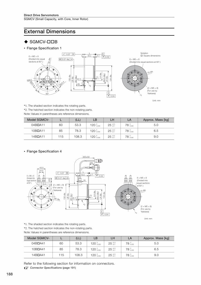
Direct Drive ServomotorsSGMCV (Small Capacity, with Core, Inner Rotor)
188
External Dimensions
SGMCV-B• Flange Specification 1
*1. The shaded section indicates the rotating parts.
*2. The hatched section indicates the non-rotating parts.
Note: Values in parentheses are reference dimensions.
• Flange Specification 4
*1. The shaded section indicates the rotating parts.
*2. The hatched section indicates the non-rotating parts.
Note: Values in parentheses are reference dimensions.
Refer to the following section for information on connectors. Connector Specifications (page 191)
Model SGMCV- L (LL) LB LH LA Approx. Mass [kg]
04BA11 60 53.3 120 25 78 5.0
10BA11 85 78.3 120 25 78 6.5
14BA11 115 108.3 120 25 78 9.0
Model SGMCV- L (LL) LB LH LA Approx. Mass [kg]
04BA41 60 53.3 120 25 78 5.0
10BA41 85 78.3 120 25 78 6.5
14BA41 115 108.3 120 25 78 9.0
23
.4
25.4
(1)
2.74
90°
R26.5
(LL)L
(9)
(0.1)
A
0.04
B
0.02
A
0.07 B
*1
*2
6 × M5 × 8
(Divided into equal
sections at 60°.)
(82
dia
.)
13
4 d
ia.
(58
.5 d
ia.)
LB
dia
.
13
5 d
ia.
0.07 dia. 6 × M5 × 8
(Divided into equal sections at 60°.)
(2 × M5 × 8)
(For use by
Yaskawa)
70 dia.
Unit: mm
90 d
ia.
LA
dia
.
LH
dia
.
Notation
: Square dimensions
0-0.035
+0.3+0.1
0-0.030
0-0.035
+0.3+0.1
0-0.030
0-0.035
+0.3+0.1
0-0.030
(1)
2.7(LL)
L
300±50
(35)
18
4
(0.1)
43.5
24.5
10
(22
)
A
0.04
B
0.02
0.07 B
A
90 dia.
*1
*2
6 × M5 × 8
(Divided into
equal sections
at 60°.)
0.07 dia.
(2 × M5 × 8)
(For use by
Yaskawa)
13
4 d
ia.
(58
.5 d
ia.)
LH
dia
.
(80
dia
.)
13
5 d
ia.
6 × M5 × 8
(Divided into
equal sections
at 60°.)
(2 × M5 × 8)
(For use by
Yaskawa)
Unit: mm
70 dia.
LB
dia
.
LA
dia
.
0-0.035
+0.3+0.1
0-0.030
0-0.035
+0.3+0.1
0-0.030
0-0.035
+0.3+0.1
0-0.030
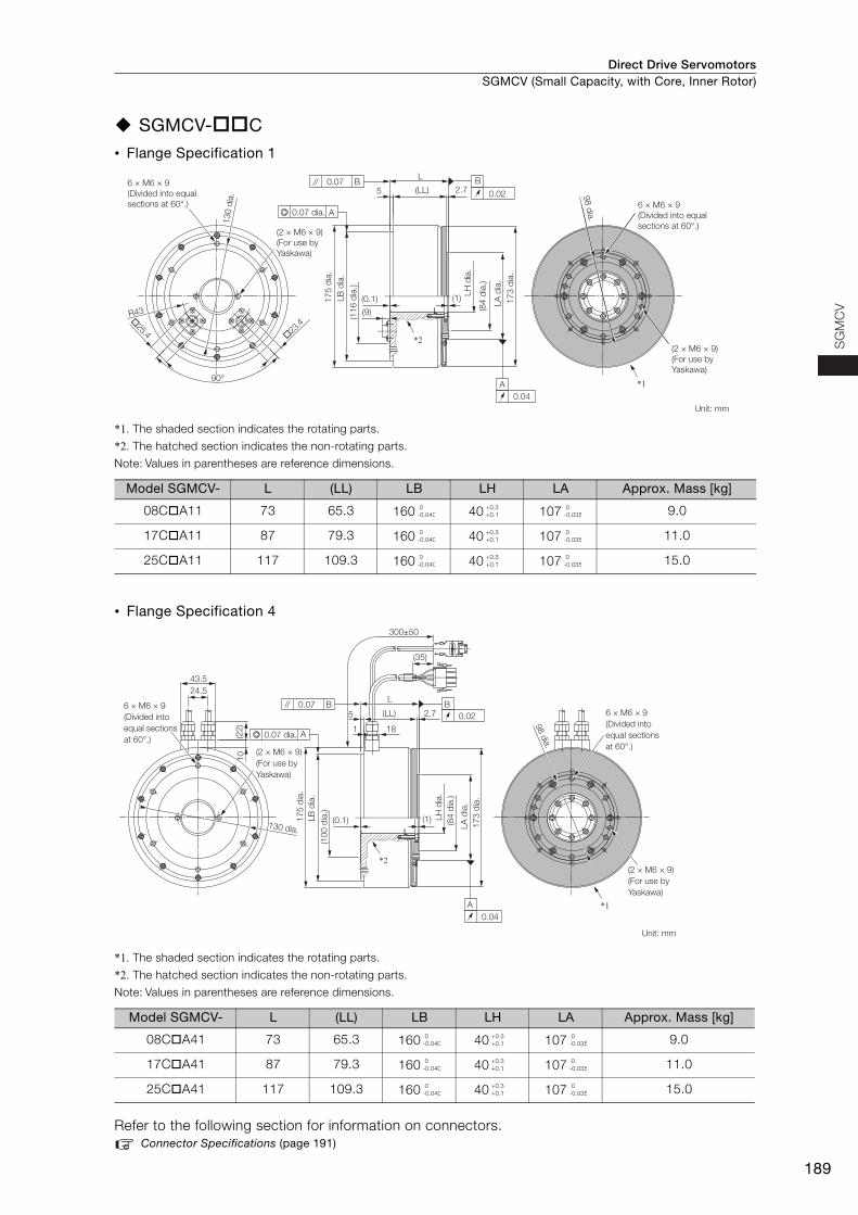
Direct Drive Servomotors SGMCV (Small Capacity, with Core, Inner Rotor)
189
SG
MC
V
SGMCV-C
• Flange Specification 1
*1. The shaded section indicates the rotating parts.
*2. The hatched section indicates the non-rotating parts.
Note: Values in parentheses are reference dimensions.
• Flange Specification 4
*1. The shaded section indicates the rotating parts.
*2. The hatched section indicates the non-rotating parts.
Note: Values in parentheses are reference dimensions.
Refer to the following section for information on connectors.Connector Specifications (page 191)
Model SGMCV- L (LL) LB LH LA Approx. Mass [kg]
08CA11 73 65.3 160 40 107 9.0
17CA11 87 79.3 160 40 107 11.0
25CA11 117 109.3 160 40 107 15.0
Model SGMCV- L (LL) LB LH LA Approx. Mass [kg]
08CA41 73 65.3 160 40 107 9.0
17CA41 87 79.3 160 40 107 11.0
25CA41 117 109.3 160 40 107 15.0
23
.4
25.4
2.75
R43
(0.1) (1)
90°
L
(LL)
(9)
B
0.02
A
0.04
0.07 B
A
17
3 d
ia.
*1
*2
130 d
ia.
6 × M6 × 9
(Divided into equal
sections at 60°.)
98 d
ia.
(2 × M6 × 9)
(For use by
Yaskawa)
Unit: mm
(2 × M6 × 9)
(For use by
Yaskawa)
LA
dia
.
(84
dia
.)
(11
6 d
ia.)
17
5 d
ia.
0.07 dia.
LB
dia
.
LH
dia
.
6 × M6 × 9
(Divided into equal
sections at 60°.)
0-0.040
+0.3+0.1
0-0.035
0-0.040
+0.3+0.1
0-0.035
0-0.040
+0.3+0.1
0-0.035
B
0.022.75
1
(0.1) (1)
L
18
300±50
(LL)
24.5
(22
)
43.5
10
(35)
0.07 B
A
A
0.04
*1
*2
6 × M6 × 9
(Divided into
equal sections
at 60°.)
(2 × M6 × 9)
(For use by
Yaskawa)
17
3 d
ia.
(84
dia
.)
17
5 d
ia.
130 dia.
6 × M6 × 9
(Divided into
equal sections
at 60°.)
98 d
ia.
(2 × M6 × 9)
(For use by
Yaskawa)
Unit: mm
(10
0 d
ia.)
0.07 dia.
LB
dia
.
LH
dia
.
LA
dia
.
0-0.040
+0.3+0.1
0-0.035
0-0.040
+0.3+0.1
0-0.035
0-0.040
+0.3+0.1
0-0.035

Direct Drive ServomotorsSGMCV (Small Capacity, with Core, Inner Rotor)
190
SGMCV-D
• Flange Specification 1
*1. The shaded section indicates the rotating parts.
*2. The hatched section indicates the non-rotating parts.
Note: Values in parentheses are reference dimensions.
• Flange Specification 4
*1. The shaded section indicates the rotating parts.
*2. The hatched section indicates the non-rotating parts.
Note: Values in parentheses are reference dimensions.
Refer to the following section for information on connectors.Connector Specifications (page 191)
Model SGMCV- L (LL) LB LH LA Approx. Mass [kg]
16DA11 78 70 200 60 145 16.0
35DA11 107 99 200 60 145 25.0
Model SGMCV- L (LL) LB LH LA Approx. Mass [kg]
16DA41 78 70 200 60 145 16.0
35DA41 107 99 200 60 145 25.0
Unit: mm
60°
�25.4 �23.4
8 × M6 × 10
(Divided into equal
sections at 45°.)(2 × M6 × 10)
(For use by Yaskawa)
(6 × M6 × 10)
(For use by Yaskawa)
R55R55
160 d
ia.
160 d
ia.
160 d
ia.
R55
L(LL)5 3
B
0.02
A
0.04
23
0 d
ia.
LB
dia
.
(14
0 d
ia.)
(0.1)
(9.2) 22
8 d
ia.
LA
dia
.
(12
0 d
ia.)
LH
dia
.
(1)
0.08 B
A0.08 dia.
*2
8 × M6 × 10
(Divided into equal
sections at 45°.)
(2 × M6 × 10)
(For use
by Yaskawa)
*1
135 d
ia.
0-0.046
+0.40
0-0.040
0-0.046
+0.40
0-0.040
Unit: mm
24.5
43.5
(6 × M6 × 10)
(For use by Yaskawa)
(2 × M6 × 10)
(For use by Yaskawa)
8 × M6 × 10(Divided into equal sections at 45°.)
(22
)1
0
(1)
22
8 d
ia.
LA
dia
.
(12
0 d
ia.)
LH
dia
.
0.08 B
A0.08 dia.
(0.1)
23
0 d
ia.
LB
dia
.
(14
0 d
ia.)
300 ±50
(35)
(LL)L
3
18
5
2.5
A
0.04
B
0.02
*2
8 × M6 × 10(Divided into equal sections at 45°.)
(2 × M6 × 10)(For use by Yaskawa)
135 d
ia.
*1
160 d
ia.
160 d
ia.
160 d
ia.
0-0.046
+0.40
0-0.040
0-0.046
+0.40
0-0.040
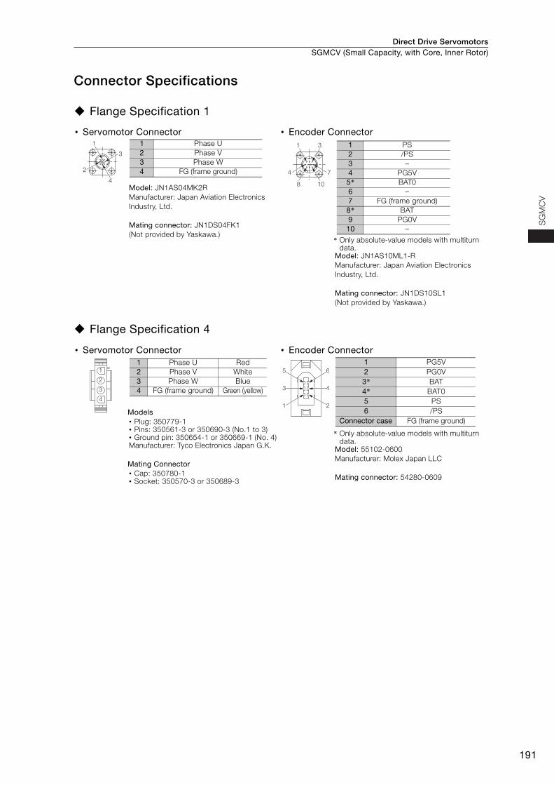
Direct Drive Servomotors SGMCV (Small Capacity, with Core, Inner Rotor)
191
SG
MC
V
Connector Specifications
Flange Specification 1
Flange Specification 4
• Servomotor Connector • Encoder Connector
Model: JN1AS04MK2RManufacturer: Japan Aviation Electronics Industry, Ltd.
Mating connector: JN1DS04FK1 (Not provided by Yaskawa.)
* Only absolute-value models with multiturn data.
Model: JN1AS10ML1-R Manufacturer: Japan Aviation Electronics Industry, Ltd.
Mating connector: JN1DS10SL1 (Not provided by Yaskawa.)
• Servomotor Connector • Encoder Connector
Models • Plug: 350779-1 • Pins: 350561-3 or 350690-3 (No.1 to 3) • Ground pin: 350654-1 or 350669-1 (No. 4) Manufacturer: Tyco Electronics Japan G.K.
Mating Connector • Cap: 350780-1 • Socket: 350570-3 or 350689-3
* Only absolute-value models with multiturn data.
Model: 55102-0600Manufacturer: Molex Japan LLC
Mating connector: 54280-0609
1
3
2
4
1 Phase U2 Phase V3 Phase W4 FG (frame ground)
1 3
4 7
8 10
1 PS2 /PS3 –4 PG5V5* BAT06 –7 FG (frame ground)8* BAT9 PG0V
10 –
1
2
3
4
1 Phase U Red2 Phase V White3 Phase W Blue4 FG (frame ground) Green (yellow) 4
2
6
3
1
5
1 PG5V2 PG0V3* BAT4* BAT05 PS6 /PS
Connector case FG (frame ground)
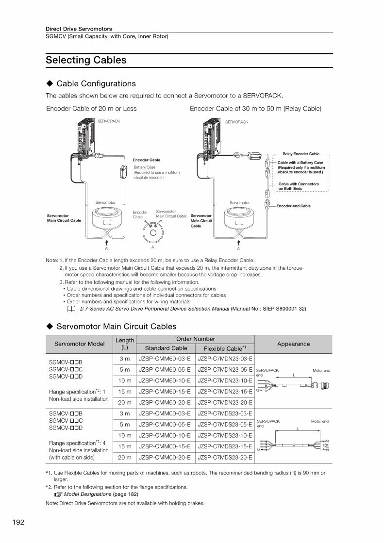
Direct Drive ServomotorsSGMCV (Small Capacity, with Core, Inner Rotor)
192
Selecting Cables
Cable ConfigurationsThe cables shown below are required to connect a Servomotor to a SERVOPACK.
Note: 1. If the Encoder Cable length exceeds 20 m, be sure to use a Relay Encoder Cable.
2. If you use a Servomotor Main Circuit Cable that exceeds 20 m, the intermittent duty zone in the torque-motor speed characteristics will become smaller because the voltage drop increases.
3. Refer to the following manual for the following information.• Cable dimensional drawings and cable connection specifications• Order numbers and specifications of individual connectors for cables• Order numbers and specifications for wiring materials
Σ-7-Series AC Servo Drive Peripheral Device Selection Manual (Manual No.: SIEP S800001 32)
Servomotor Main Circuit Cables
*1. Use Flexible Cables for moving parts of machines, such as robots. The recommended bending radius (R) is 90 mm or larger.
*2. Refer to the following section for the flange specifications.Model Designations (page 182)
Note: Direct Drive Servomotors are not available with holding brakes.
Encoder Cable of 20 m or Less Encoder Cable of 30 m to 50 m (Relay Cable)
Servomotor ModelLength
(L)
Order NumberAppearance
Standard Cable Flexible Cable*1
SGMCV-BSGMCV-CSGMCV-D
Flange specification*2: 1Non-load side installation
3 m JZSP-CMM60-03-E JZSP-C7MDN23-03-E
5 m JZSP-CMM60-05-E JZSP-C7MDN23-05-E
10 m JZSP-CMM60-10-E JZSP-C7MDN23-10-E
15 m JZSP-CMM60-15-E JZSP-C7MDN23-15-E
20 m JZSP-CMM60-20-E JZSP-C7MDN23-20-E
SGMCV-BSGMCV-CSGMCV-D
Flange specification*2: 4Non-load side installation (with cable on side)
3 m JZSP-CMM00-03-E JZSP-C7MDS23-03-E
5 m JZSP-CMM00-05-E JZSP-C7MDS23-05-E
10 m JZSP-CMM00-10-E JZSP-C7MDS23-10-E
15 m JZSP-CMM00-15-E JZSP-C7MDS23-15-E
20 m JZSP-CMM00-20-E JZSP-C7MDS23-20-E
SERVOPACK
Encoder Cable
Encoder
Cable
Servomotor
Servomotor Main Circuit Cable
Servomotor
Main Circuit Cable
A A
Battery Case
(Required to use a multiturn
absolute encoder.)
SERVOPACK
Cable with a Battery Case(Required only if a multiturn absolute encoder is used.)
Cable with Connectors on Both Ends
Encoder-end CableServomotor
Servomotor Main Circuit Cable
A
Relay Encoder Cable
LSERVOPACK end
Motor end
L
SERVOPACK end
Motor end
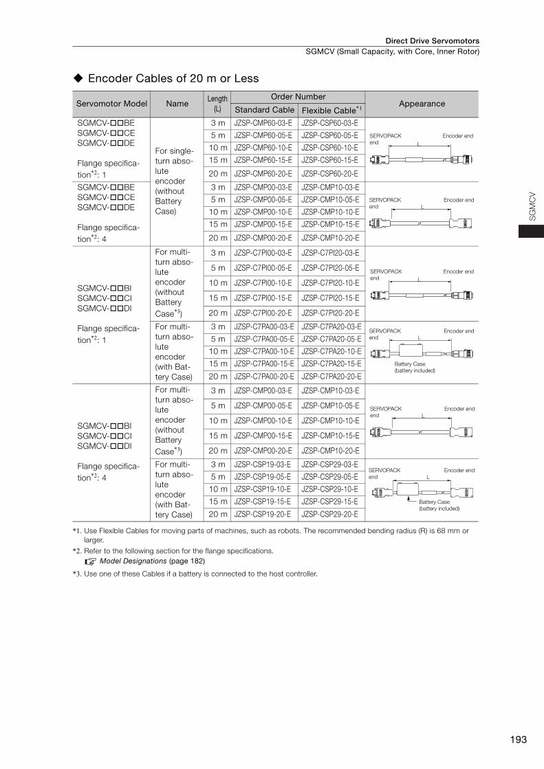
Direct Drive Servomotors SGMCV (Small Capacity, with Core, Inner Rotor)
193
SG
MC
V
Encoder Cables of 20 m or Less
*1. Use Flexible Cables for moving parts of machines, such as robots. The recommended bending radius (R) is 68 mm or larger.
*2. Refer to the following section for the flange specifications.Model Designations (page 182)
*3. Use one of these Cables if a battery is connected to the host controller.
Servomotor Model NameLength
(L)
Order NumberAppearance
Standard Cable Flexible Cable*1
SGMCV-BESGMCV-CESGMCV-DE
Flange specifica-tion*2: 1
For single-turn abso-lute encoder(without Battery Case)
3 m JZSP-CMP60-03-E JZSP-CSP60-03-E
5 m JZSP-CMP60-05-E JZSP-CSP60-05-E
10 m JZSP-CMP60-10-E JZSP-CSP60-10-E
15 m JZSP-CMP60-15-E JZSP-CSP60-15-E
20 m JZSP-CMP60-20-E JZSP-CSP60-20-E
SGMCV-BESGMCV-CESGMCV-DE
Flange specifica-tion*2: 4
3 m JZSP-CMP00-03-E JZSP-CMP10-03-E
5 m JZSP-CMP00-05-E JZSP-CMP10-05-E
10 m JZSP-CMP00-10-E JZSP-CMP10-10-E
15 m JZSP-CMP00-15-E JZSP-CMP10-15-E
20 m JZSP-CMP00-20-E JZSP-CMP10-20-E
SGMCV-BISGMCV-CISGMCV-DI
Flange specifica-tion*2: 1
For multi-turn abso-lute encoder (without Battery Case*3)
3 m JZSP-C7PI00-03-E JZSP-C7PI20-03-E
5 m JZSP-C7PI00-05-E JZSP-C7PI20-05-E
10 m JZSP-C7PI00-10-E JZSP-C7PI20-10-E
15 m JZSP-C7PI00-15-E JZSP-C7PI20-15-E
20 m JZSP-C7PI00-20-E JZSP-C7PI20-20-E
For multi-turn abso-lute encoder(with Bat-tery Case)
3 m JZSP-C7PA00-03-E JZSP-C7PA20-03-E
5 m JZSP-C7PA00-05-E JZSP-C7PA20-05-E
10 m JZSP-C7PA00-10-E JZSP-C7PA20-10-E
15 m JZSP-C7PA00-15-E JZSP-C7PA20-15-E
20 m JZSP-C7PA00-20-E JZSP-C7PA20-20-E
SGMCV-BISGMCV-CISGMCV-DI
Flange specifica-tion*2: 4
For multi-turn abso-lute encoder (without Battery Case*3)
3 m JZSP-CMP00-03-E JZSP-CMP10-03-E
5 m JZSP-CMP00-05-E JZSP-CMP10-05-E
10 m JZSP-CMP00-10-E JZSP-CMP10-10-E
15 m JZSP-CMP00-15-E JZSP-CMP10-15-E
20 m JZSP-CMP00-20-E JZSP-CMP10-20-E
For multi-turn abso-lute encoder(with Bat-tery Case)
3 m JZSP-CSP19-03-E JZSP-CSP29-03-E
5 m JZSP-CSP19-05-E JZSP-CSP29-05-E
10 m JZSP-CSP19-10-E JZSP-CSP29-10-E
15 m JZSP-CSP19-15-E JZSP-CSP29-15-E
20 m JZSP-CSP19-20-E JZSP-CSP29-20-E
L
SERVOPACK end
Encoder end
LSERVOPACK end
Encoder end
L
SERVOPACK end
Encoder end
SERVOPACK end
Encoder end
Battery Case (battery included)
L
LSERVOPACK end
Encoder end
SERVOPACK end
Encoder end
Battery Case (battery included)
L
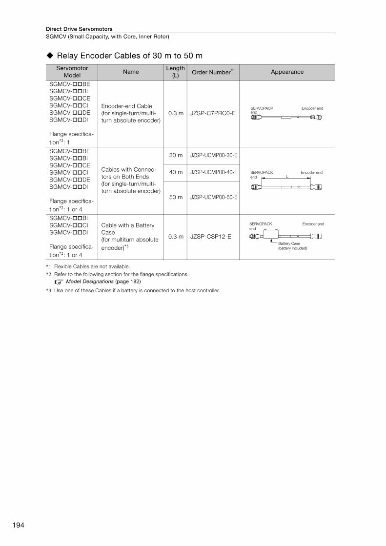
Direct Drive ServomotorsSGMCV (Small Capacity, with Core, Inner Rotor)
194
Relay Encoder Cables of 30 m to 50 m
*1. Flexible Cables are not available.
*2. Refer to the following section for the flange specifications.Model Designations (page 182)
*3. Use one of these Cables if a battery is connected to the host controller.
Servomotor Model
NameLength
(L) Order Number*1 Appearance
SGMCV-BESGMCV-BISGMCV-CESGMCV-CISGMCV-DESGMCV-DI
Flange specifica-tion*2: 1
Encoder-end Cable (for single-turn/multi-turn absolute encoder)
0.3 m JZSP-C7PRC0-E
SGMCV-BESGMCV-BISGMCV-CESGMCV-CISGMCV-DESGMCV-DI
Flange specifica-tion*2: 1 or 4
Cables with Connec-tors on Both Ends (for single-turn/multi-turn absolute encoder)
30 m JZSP-UCMP00-30-E
40 m JZSP-UCMP00-40-E
50 m JZSP-UCMP00-50-E
SGMCV-BISGMCV-CISGMCV-DI
Flange specifica-tion*2: 1 or 4
Cable with a Battery Case(for multiturn absolute encoder)*3
0.3 m JZSP-CSP12-E
SERVOPACK end
Encoder end
LSERVOPACK end
Encoder end
SERVOPACK end
Encoder end
Battery Case (battery included)
195
MEMO
SG
MC
V
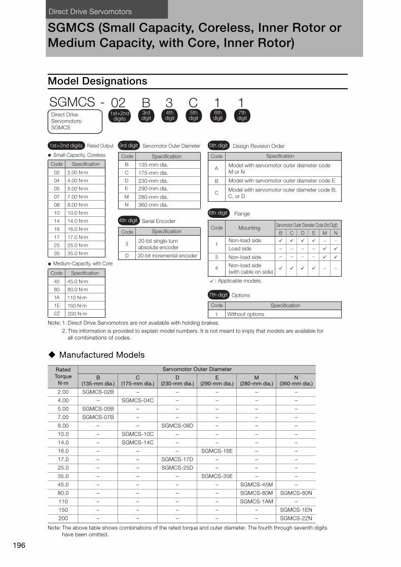
Direct Drive Servomotors
196
SGMCS (Small Capacity, Coreless, Inner Rotor or Medium Capacity, with Core, Inner Rotor)
Model Designations
Note: 1. Direct Drive Servomotors are not available with holding brakes.
2. This information is provided to explain model numbers. It is not meant to imply that models are available for all combinations of codes.
Manufactured Models
Note: The above table shows combinations of the rated torque and outer diameter. The fourth through seventh digits have been omitted.
Rated Torque
Nm
Servomotor Outer Diameter
B (135-mm dia.)
C (175-mm dia.)
D (230-mm dia.)
E (290-mm dia.)
M (280-mm dia.)
N (360-mm dia.)
2.00 SGMCS-02B – – – – –
4.00 – SGMCS-04C – – – –
5.00 SGMCS-05B – – – – –
7.00 SGMCS-07B – – – – –
8.00 – – SGMCS-08D – – –
10.0 – SGMCS-10C – – – –
14.0 – SGMCS-14C – – – –
16.0 – – – SGMCS-16E – –
17.0 – – SGMCS-17D – – –
25.0 – – SGMCS-25D – – –
35.0 – – – SGMCS-35E – –
45.0 – – – – SGMCS-45M –
80.0 – – – – SGMCS-80M SGMCS-80N
110 – – – – SGMCS-1AM –
150 – – – – – SGMCS-1EN
200 – – – – – SGMCS-2ZN
A
B
C
B
C
D
E
M
N
3
D
B
C
D
E
M
N
1
3
4
1
1A 110 Nm
1E 150 Nm
2Z 200 Nm
3rd digit 5th digit
6th digit
7th digit
Small-Capacity, Coreless
Medium-Capacity, with Core
Model with servomotor outer diameter code M or N
Model with servomotor outer diameter code E
Model with servomotor outer diameter code B, C, or D
135-mm dia.
Specification
175-mm dia.
230-mm dia.290-mm dia.
280-mm dia.360-mm dia.
Servomotor Outer Diameter
4th digit Serial Encoder
Specification
20-bit single-turn absolute encoder
20-bit incremental encoder
Design Revision Order
Flange
Mounting
Non-load side
Load side
Non-load side
Non-load side (with cable on side)
: Applicable models.
Options
Without options
Servomotor Outer Diameter Code (3rd Digit)
SGMCS - 02 B 3 C 1 11st+2nd
digits
1st+2nd digits Rated Output
Specification
Code Specification
3rd digit
4th digit
5th digit
6th digit
7th digit
Direct Drive Servomotors: SGMCS
Code
Code Specification
SpecificationCode
Code
Code
Code
02 2.00 Nm
04 4.00 Nm
05 5.00 Nm
07 7.00 Nm
08 8.00 Nm
10 10.0 Nm
14 14.0 Nm
16 16.0 Nm
17 17.0 Nm
25 25.0 Nm
35 35.0 Nm
45 45.0 Nm
80 80.0 Nm
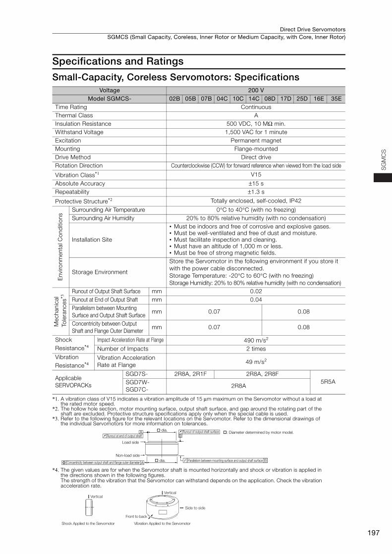
Direct Drive Servomotors SGMCS (Small Capacity, Coreless, Inner Rotor or Medium Capacity, with Core, Inner Rotor)
197
SG
MC
S
Specifications and Ratings
Small-Capacity, Coreless Servomotors: Specifications
*1. A vibration class of V15 indicates a vibration amplitude of 15 μm maximum on the Servomotor without a load at the rated motor speed.
*2. The hollow hole section, motor mounting surface, output shaft surface, and gap around the rotating part of the shaft are excluded. Protective structure specifications apply only when the special cable is used.
*3. Refer to the following figure for the relevant locations on the Servomotor. Refer to the dimensional drawings of the individual Servomotors for more information on tolerances.
*4. The given values are for when the Servomotor shaft is mounted horizontally and shock or vibration is applied in the directions shown in the following figures.The strength of the vibration that the Servomotor can withstand depends on the application. Check the vibration acceleration rate.
Voltage 200 VModel SGMCS- 02B 05B 07B 04C 10C 14C 08D 17D 25D 16E 35E
Time Rating Continuous Thermal Class AInsulation Resistance 500 VDC, 10 MΩ min. Withstand Voltage 1,500 VAC for 1 minute Excitation Permanent magnet Mounting Flange-mounted Drive Method Direct drive Rotation Direction Counterclockwise (CCW) for forward reference when viewed from the load side
Vibration Class*1 V15
Absolute Accuracy ±15 s Repeatability ±1.3 s
Protective Structure*2 Totally enclosed, self-cooled, IP42
Env
ironm
enta
l Con
diti
ons
Surrounding Air Temperature 0°C to 40°C (with no freezing) Surrounding Air Humidity 20% to 80% relative humidity (with no condensation)
Installation Site
• Must be indoors and free of corrosive and explosive gases. • Must be well-ventilated and free of dust and moisture. • Must facilitate inspection and cleaning. • Must have an altitude of 1,000 m or less.• Must be free of strong magnetic fields.
Storage Environment
Store the Servomotor in the following environment if you store it with the power cable disconnected.Storage Temperature: -20°C to 60°C (with no freezing) Storage Humidity: 20% to 80% relative humidity (with no condensation)
Mec
hani
cal
Tol
eran
ces*3
Runout of Output Shaft Surface mm 0.02Runout at End of Output Shaft mm 0.04Parallelism between Mounting Surface and Output Shaft Surface
mm 0.07 0.08
Concentricity between Output Shaft and Flange Outer Diameter
mm 0.07 0.08
Shock Resistance*4
Impact Acceleration Rate at Flange 490 m/s2
Number of Impacts 2 times Vibration Resistance*4
Vibration Acceleration Rate at Flange 49 m/s2
Applicable SERVOPACKs
SGD7S- 2R8A, 2R1F 2R8A, 2R8F5R5ASGD7W-
SGD7C-2R8A
A
AB
B
dia.
dia.
Runout of output shaft surface
Parallelism between mounting surface and output shaft surface
Runout at end of output shaft
Load side
Non-load side
Concentricity between output shaft and flange outer diameter
: Diameter determined by motor model.
Side to side
Front to back
Vertical
Shock Applied to the Servomotor Vibration Applied to the Servomotor
Vertical
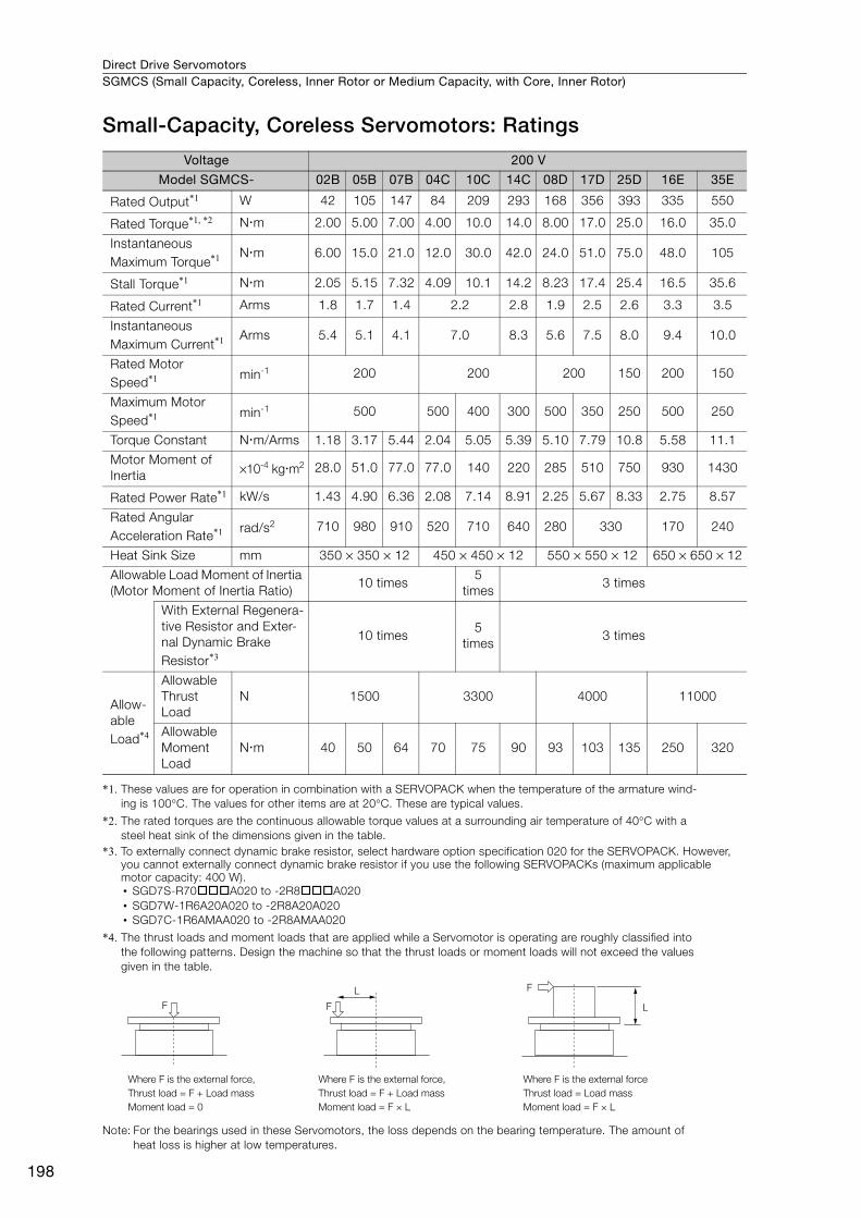
Direct Drive ServomotorsSGMCS (Small Capacity, Coreless, Inner Rotor or Medium Capacity, with Core, Inner Rotor)
198
Small-Capacity, Coreless Servomotors: Ratings
*1. These values are for operation in combination with a SERVOPACK when the temperature of the armature wind-ing is 100°C. The values for other items are at 20°C. These are typical values.
*2. The rated torques are the continuous allowable torque values at a surrounding air temperature of 40°C with a steel heat sink of the dimensions given in the table.
*3. To externally connect dynamic brake resistor, select hardware option specification 020 for the SERVOPACK. However, you cannot externally connect dynamic brake resistor if you use the following SERVOPACKs (maximum applicable motor capacity: 400 W).• SGD7S-R70A020 to -2R8A020• SGD7W-1R6A20A020 to -2R8A20A020• SGD7C-1R6AMAA020 to -2R8AMAA020
*4. The thrust loads and moment loads that are applied while a Servomotor is operating are roughly classified into the following patterns. Design the machine so that the thrust loads or moment loads will not exceed the values given in the table.
Note: For the bearings used in these Servomotors, the loss depends on the bearing temperature. The amount of heat loss is higher at low temperatures.
Voltage 200 V
Model SGMCS- 02B 05B 07B 04C 10C 14C 08D 17D 25D 16E 35E
Rated Output*1 W 42 105 147 84 209 293 168 356 393 335 550
Rated Torque*1, *2 Nm 2.00 5.00 7.00 4.00 10.0 14.0 8.00 17.0 25.0 16.0 35.0
Instantaneous Maximum Torque*1 Nm 6.00 15.0 21.0 12.0 30.0 42.0 24.0 51.0 75.0 48.0 105
Stall Torque*1 Nm 2.05 5.15 7.32 4.09 10.1 14.2 8.23 17.4 25.4 16.5 35.6
Rated Current*1 Arms 1.8 1.7 1.4 2.2 2.8 1.9 2.5 2.6 3.3 3.5
Instantaneous Maximum Current*1 Arms 5.4 5.1 4.1 7.0 8.3 5.6 7.5 8.0 9.4 10.0
Rated Motor Speed*1 min-1 200 200 200 150 200 150
Maximum Motor Speed*1 min-1 500 500 400 300 500 350 250 500 250
Torque Constant Nm/Arms 1.18 3.17 5.44 2.04 5.05 5.39 5.10 7.79 10.8 5.58 11.1
Motor Moment of Inertia ×10-4 kgm2 28.0 51.0 77.0 77.0 140 220 285 510 750 930 1430
Rated Power Rate*1 kW/s 1.43 4.90 6.36 2.08 7.14 8.91 2.25 5.67 8.33 2.75 8.57
Rated Angular Acceleration Rate*1 rad/s2 710 980 910 520 710 640 280 330 170 240
Heat Sink Size mm 350 × 350 × 12 450 × 450 × 12 550 × 550 × 12 650 × 650 × 12
Allowable Load Moment of Inertia (Motor Moment of Inertia Ratio)
10 times5
times3 times
With External Regenera-tive Resistor and Exter-nal Dynamic Brake Resistor*3
10 times5
times3 times
Allow-able Load*4
Allowable Thrust Load
N 1500 3300 4000 11000
Allowable Moment Load
Nm 40 50 64 70 75 90 93 103 135 250 320
F
F
LF
L
Where F is the external force,
Thrust load = F + Load mass
Moment load = 0
Where F is the external force
Thrust load = Load mass
Moment load = F × L
Where F is the external force,
Thrust load = F + Load mass
Moment load = F × L
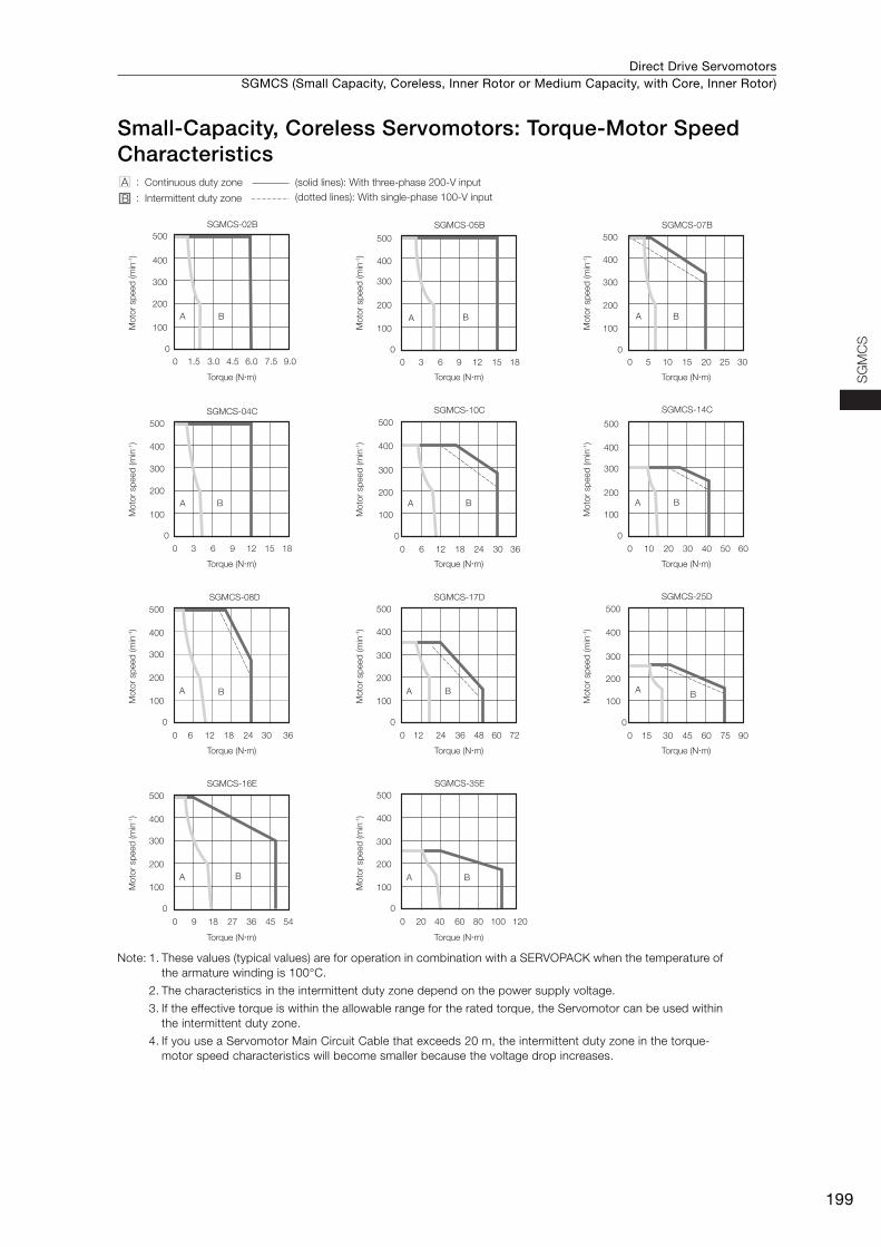
Direct Drive Servomotors SGMCS (Small Capacity, Coreless, Inner Rotor or Medium Capacity, with Core, Inner Rotor)
199
SG
MC
S
Small-Capacity, Coreless Servomotors: Torque-Motor Speed Characteristics
Note: 1. These values (typical values) are for operation in combination with a SERVOPACK when the temperature of the armature winding is 100°C.
2. The characteristics in the intermittent duty zone depend on the power supply voltage.
3. If the effective torque is within the allowable range for the rated torque, the Servomotor can be used within the intermittent duty zone.
4. If you use a Servomotor Main Circuit Cable that exceeds 20 m, the intermittent duty zone in the torque-motor speed characteristics will become smaller because the voltage drop increases.
SGMCS-02B
A
0
0
100
1.5 3.0 4.5 6.0 7.5 9.0
200
300
400
500
B
SGMCS-05B
A
0
0
100
3 6 9 12 15 18
200
300
400
500
B
SGMCS-07B
A
0
0
100
5 10 15 20 25 30
200
300
400
500
B
SGMCS-04C
A
0
0
100
3 6 9 12 15 18
200
300
400
500
B
SGMCS-10C
A
0
0
100
6 12 18 24 30 36
200
300
400
500
B
SGMCS-14C
A
0
0
100
10 20 30 40 50 60
200
300
400
500
B
100
200
300
400
500
SGMCS-08D
0
0
100
6 12 18 24 30 36
200
300
400
500
SGMCS-17D
A
0
0
12 24 36 48 60 72
B
100
200
300
400
500
SGMCS-16E
A
0
0
100
9 18 27 36 45 54
200
300
400
500
B
SGMCS-35E
A
0
0
20 40 60 80 100 120
B
SGMCS-25D
A
0
0
100
15 30 45 60 75 90
200
300
400
500
BA B
A :
B :
Continuous duty zone (solid lines): With three-phase 200-V input
(dotted lines): With single-phase 100-V inputIntermittent duty zone
Torque (N�m)
Mo
tor
sp
eed
(m
in-1)
Torque (N�m)
Mo
tor
sp
eed
(m
in-1)
Torque (N�m)
Mo
tor
sp
eed
(m
in-1)
Torque (N�m)
Mo
tor
sp
eed
(m
in-1)
Torque (N�m)
Mo
tor
sp
eed
(m
in-1)
Torque (N�m)
Mo
tor
sp
eed
(m
in-1)
Torque (N�m)
Mo
tor
sp
eed
(m
in-1)
Torque (N�m)
Mo
tor
sp
eed
(m
in-1)
Torque (N�m)
Mo
tor
sp
eed
(m
in-1)
Torque (N�m)
Mo
tor
sp
eed
(m
in-1)
Torque (N�m)
Mo
tor
sp
eed
(m
in-1)
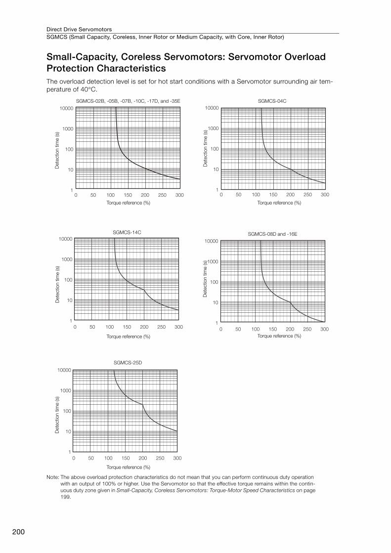
Direct Drive ServomotorsSGMCS (Small Capacity, Coreless, Inner Rotor or Medium Capacity, with Core, Inner Rotor)
200
Small-Capacity, Coreless Servomotors: Servomotor Overload Protection CharacteristicsThe overload detection level is set for hot start conditions with a Servomotor surrounding air tem-perature of 40°C.
Note: The above overload protection characteristics do not mean that you can perform continuous duty operation with an output of 100% or higher. Use the Servomotor so that the effective torque remains within the contin-uous duty zone given in Small-Capacity, Coreless Servomotors: Torque-Motor Speed Characteristics on page 199.
SGMCS-02B, -05B, -07B, -10C, -17D, and -35E SGMCS-04C
SGMCS-14C
SGMCS-25D
SGMCS-08D and -16E
Det
ectio
n tim
e (s
)
Torque reference (%)D
etec
tion
time
(s)
Det
ectio
n tim
e (s
)
Det
ectio
n tim
e (s
)D
etec
tion
time
(s)
Torque reference (%)
Torque reference (%) Torque reference (%)
Torque reference (%)
0 50 100 150 200 250 300
10000
1000
100
10
10 50 100 150 200 250 300
10000
1000
100
10
1
0 50 100 150 200 250 300
10000
1000
100
10
1
0 50 100 150 200 250 300
10000
1000
100
10
1
0 50 100 150 200 250 300
10000
1000
100
10
1
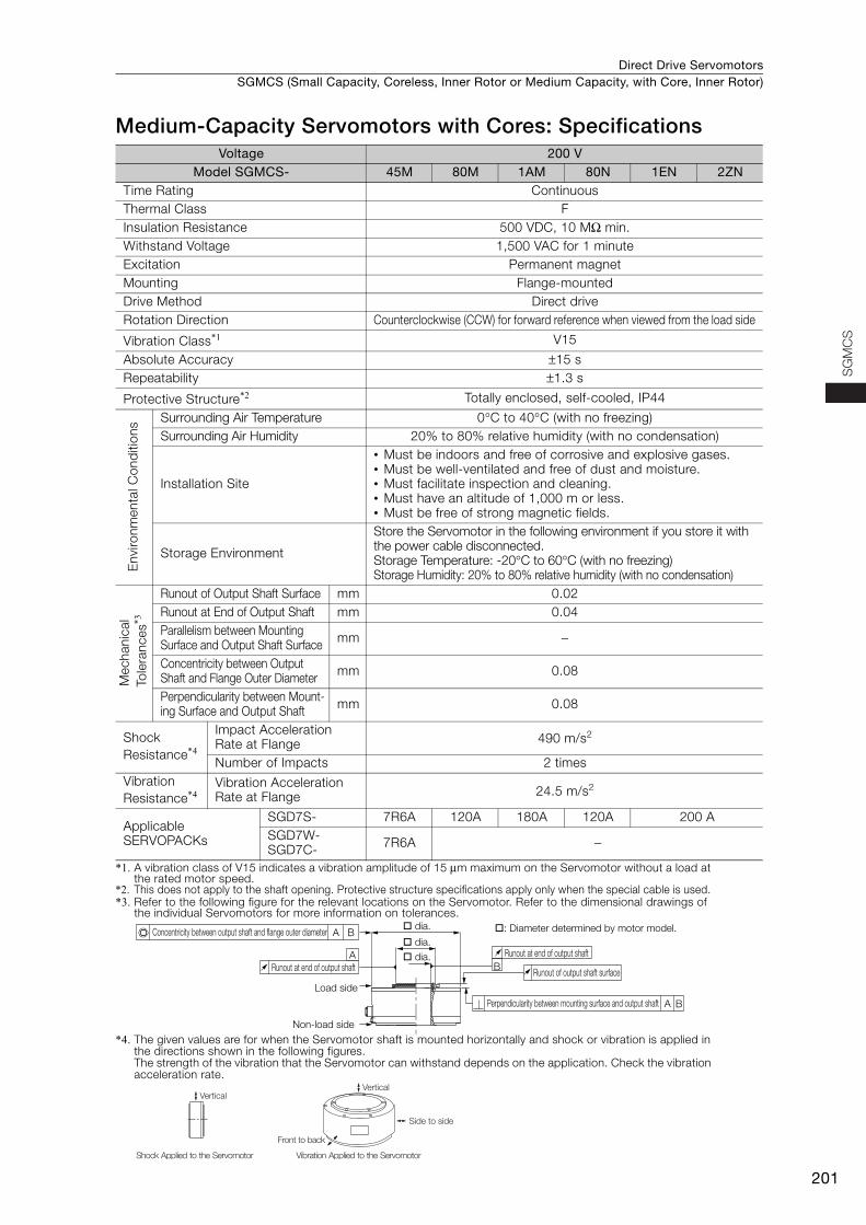
Direct Drive Servomotors SGMCS (Small Capacity, Coreless, Inner Rotor or Medium Capacity, with Core, Inner Rotor)
201
SG
MC
S
Medium-Capacity Servomotors with Cores: Specifications
*1. A vibration class of V15 indicates a vibration amplitude of 15 μm maximum on the Servomotor without a load at the rated motor speed.
*2. This does not apply to the shaft opening. Protective structure specifications apply only when the special cable is used. *3. Refer to the following figure for the relevant locations on the Servomotor. Refer to the dimensional drawings of
the individual Servomotors for more information on tolerances.
*4. The given values are for when the Servomotor shaft is mounted horizontally and shock or vibration is applied in the directions shown in the following figures.The strength of the vibration that the Servomotor can withstand depends on the application. Check the vibration acceleration rate.
Voltage 200 VModel SGMCS- 45M 80M 1AM 80N 1EN 2ZN
Time Rating Continuous Thermal Class FInsulation Resistance 500 VDC, 10 MΩ min. Withstand Voltage 1,500 VAC for 1 minute Excitation Permanent magnet Mounting Flange-mounted Drive Method Direct drive Rotation Direction Counterclockwise (CCW) for forward reference when viewed from the load side
Vibration Class*1 V15
Absolute Accuracy ±15 s Repeatability ±1.3 s
Protective Structure*2 Totally enclosed, self-cooled, IP44
Env
ironm
enta
l Con
diti
ons Surrounding Air Temperature 0°C to 40°C (with no freezing)
Surrounding Air Humidity 20% to 80% relative humidity (with no condensation)
Installation Site
• Must be indoors and free of corrosive and explosive gases.• Must be well-ventilated and free of dust and moisture.• Must facilitate inspection and cleaning.• Must have an altitude of 1,000 m or less.• Must be free of strong magnetic fields.
Storage Environment
Store the Servomotor in the following environment if you store it with the power cable disconnected.Storage Temperature: -20°C to 60°C (with no freezing) Storage Humidity: 20% to 80% relative humidity (with no condensation)
Mec
hani
cal
Tol
eran
ces*3
Runout of Output Shaft Surface mm 0.02Runout at End of Output Shaft mm 0.04Parallelism between Mounting Surface and Output Shaft Surface mm −
Concentricity between Output Shaft and Flange Outer Diameter mm 0.08
Perpendicularity between Mount-ing Surface and Output Shaft mm 0.08
Shock Resistance*4
Impact Acceleration Rate at Flange 490 m/s2
Number of Impacts 2 times Vibration Resistance*4
Vibration Acceleration Rate at Flange 24.5 m/s2
Applicable SERVOPACKs
SGD7S- 7R6A 120A 180A 120A 200 ASGD7W-SGD7C- 7R6A −
B
A
A
A B
B
Runout at end of output shaft
Runout of output shaft surface
Perpendicularity between mounting surface and output shaft
Concentricity between output shaft and flange outer diameter
Runout at end of output shaft
Load side
Non-load side
dia. : Diameter determined by motor model. dia. dia.
Side to side
Front to back
Vertical
Shock Applied to the Servomotor Vibration Applied to the Servomotor
Vertical
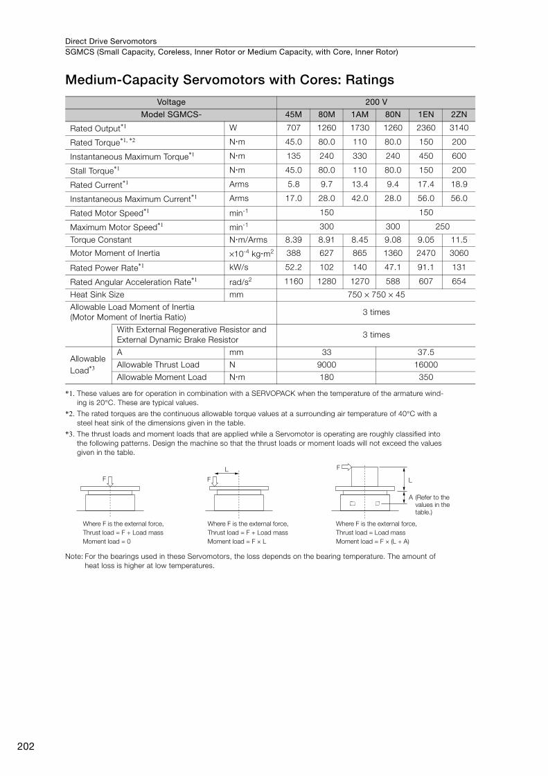
Direct Drive ServomotorsSGMCS (Small Capacity, Coreless, Inner Rotor or Medium Capacity, with Core, Inner Rotor)
202
Medium-Capacity Servomotors with Cores: Ratings
*1. These values are for operation in combination with a SERVOPACK when the temperature of the armature wind-ing is 20°C. These are typical values.
*2. The rated torques are the continuous allowable torque values at a surrounding air temperature of 40°C with a steel heat sink of the dimensions given in the table.
*3. The thrust loads and moment loads that are applied while a Servomotor is operating are roughly classified into the following patterns. Design the machine so that the thrust loads or moment loads will not exceed the values given in the table.
Note: For the bearings used in these Servomotors, the loss depends on the bearing temperature. The amount of heat loss is higher at low temperatures.
Voltage 200 V
Model SGMCS- 45M 80M 1AM 80N 1EN 2ZN
Rated Output*1 W 707 1260 1730 1260 2360 3140
Rated Torque*1, *2 Nm 45.0 80.0 110 80.0 150 200
Instantaneous Maximum Torque*1 Nm 135 240 330 240 450 600
Stall Torque*1 Nm 45.0 80.0 110 80.0 150 200
Rated Current*1 Arms 5.8 9.7 13.4 9.4 17.4 18.9
Instantaneous Maximum Current*1 Arms 17.0 28.0 42.0 28.0 56.0 56.0
Rated Motor Speed*1 min-1 150 150
Maximum Motor Speed*1 min-1 300 300 250
Torque Constant Nm/Arms 8.39 8.91 8.45 9.08 9.05 11.5
Motor Moment of Inertia ×10-4 kgm2 388 627 865 1360 2470 3060
Rated Power Rate*1 kW/s 52.2 102 140 47.1 91.1 131
Rated Angular Acceleration Rate*1 rad/s2 1160 1280 1270 588 607 654
Heat Sink Size mm 750 × 750 × 45
Allowable Load Moment of Inertia (Motor Moment of Inertia Ratio)
3 times
With External Regenerative Resistor and External Dynamic Brake Resistor
3 times
Allowable Load*3
A mm 33 37.5
Allowable Thrust Load N 9000 16000
Allowable Moment Load Nm 180 350
F F
L F
L
Where F is the external force,
Thrust load = F + Load mass
Moment load = 0
Where F is the external force,
Thrust load = F + Load mass
Moment load = F × L
Where F is the external force,
Thrust load = Load mass
Moment load = F × (L + A)
A (Refer to the
values in the
table.)
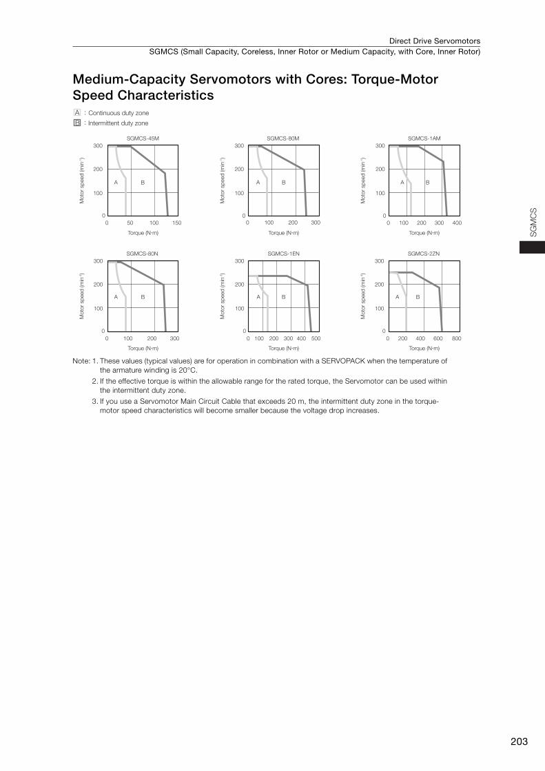
Direct Drive Servomotors SGMCS (Small Capacity, Coreless, Inner Rotor or Medium Capacity, with Core, Inner Rotor)
203
SG
MC
S
Medium-Capacity Servomotors with Cores: Torque-Motor Speed Characteristics
Note: 1. These values (typical values) are for operation in combination with a SERVOPACK when the temperature of the armature winding is 20°C.
2. If the effective torque is within the allowable range for the rated torque, the Servomotor can be used within the intermittent duty zone.
3. If you use a Servomotor Main Circuit Cable that exceeds 20 m, the intermittent duty zone in the torque-motor speed characteristics will become smaller because the voltage drop increases.
A
0 50 100 150
0
100
200
300
B A
0 100 200 300
0
100
200
300
B
SGMCS-45M SGMCS-80M
A
0 100 200 300 400
0
100
200
300
B
A
0 100 200 300
0
100
200
300
B
SGMCS-1AM
SGMCS-80N
A
0 100 200 300 400 500
0
100
200
300
B A
0 200 400 600 800
0
100
200
300
B
SGMCS-1EN SGMCS-2ZN
A :
B :
Continuous duty zone
Intermittent duty zone
Torque (N�m)
Mo
tor
sp
eed
(m
in-1)
Torque (N�m)
Mo
tor
sp
eed
(m
in-1)
Torque (N�m)
Mo
tor
sp
eed
(m
in-1)
Torque (N�m)
Mo
tor
sp
eed
(m
in-1)
Torque (N�m)
Mo
tor
sp
eed
(m
in-1)
Torque (N�m)
Mo
tor
sp
eed
(m
in-1)
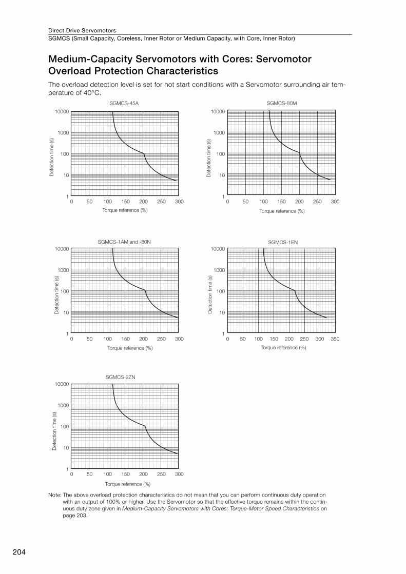
Direct Drive ServomotorsSGMCS (Small Capacity, Coreless, Inner Rotor or Medium Capacity, with Core, Inner Rotor)
204
Medium-Capacity Servomotors with Cores: Servomotor Overload Protection CharacteristicsThe overload detection level is set for hot start conditions with a Servomotor surrounding air tem-perature of 40°C.
Note: The above overload protection characteristics do not mean that you can perform continuous duty operation with an output of 100% or higher. Use the Servomotor so that the effective torque remains within the contin-uous duty zone given in Medium-Capacity Servomotors with Cores: Torque-Motor Speed Characteristics on page 203.
10000
1000
100
10
1
10000
1000
100
10
1
10000
1000
100
10
1
10000
1000
100
10
1
10000
1000
100
10
1
0 50 100 150 200 250 300 0 50 100 150 200 250 300
0 50 100 150 200 250 300
0 50 100 150 200 250 300
0 50 100 150 200 250 300 350
SGMCS-45A SGMCS-80M
SGMCS-1AM and -80N
SGMCS-2ZN
SGMCS-1EN
Dete
ctio
n t
ime (s)
Torque reference (%)D
ete
ctio
n t
ime (s)
Torque reference (%)
Dete
ctio
n t
ime (s)
Torque reference (%)
Dete
ctio
n t
ime (s)
Torque reference (%)
Dete
ctio
n t
ime (s)
Torque reference (%)
Direct Drive Servomotors SGMCS (Small Capacity, Coreless, Inner Rotor or Medium Capacity, with Core, Inner Rotor)
205
SG
MC
S
Allowable Load Moment of InertiaThe allowable load moments of inertia (motor moment of inertia ratios) for the Servomotors are given in the Small-Capacity, Coreless Servomotors: Ratings (page 198) and Medium-Capacity Servomo-tors with Cores: Ratings (page 202). The values are determined by the regenerative energy process-ing capacity of the SERVOPACK and are also affected by the drive conditions of the Servomotor. Perform the required Steps for each of the following cases.
Use the SigmaSize+ AC Servo Drive Capacity Selection Program to check the driving conditions. Contact your Yaskawa representative for information on this program.
Exceeding the Allowable Load Moment of InertiaUse one of the following measures to adjust the load moment of inertia to within the allowable value.• Reduce the torque limit.• Reduce the deceleration rate.• Reduce the maximum motor speed.
If the above steps is not possible, install an external regenerative resistor.
An Overvoltage Alarm (A.400) is likely to occur during deceleration if the load moment of iner-tia exceeds the allowable load moment of inertia. SERVOPACKs with a built-in regenerative resistor may generate a Regenerative Overload Alarm (A.320). Refer to Built-In Regenerative Resistor (page 472) for the regenerative power (W) that can be processed by the SERVO-PACKs.Install an External Regenerative Resistor when the built-in regenerative resistor cannot pro-cess all of the regenerative power.
Information

Direct Drive ServomotorsSGMCS (Small Capacity, Coreless, Inner Rotor or Medium Capacity, with Core, Inner Rotor)
206
SERVOPACKs without Built-in Regenerative ResistorsThe following graph shows the allowable load moment of inertia scaling factor of the motor speed (reference values for deceleration operation at or above the rated torque). Application is possible without an external regenerative resistor within the allowable value. However, an External Regenera-tive Resistor is required in the shaded areas of the graphs.
Note: Applicable SERVOPACK models: SGD7S-2R8A and -2R8F
When an External Regenerative Resistor Is RequiredInstall the External Regenerative Resistor. Refer to the following section for the recommended products.
External Regenerative Resistors (page 472)
0
2
4
6
8
10
12
0 100 200 300 400 500 600
SGMCS-02B
0
2
4
6
8
10
12
0 100 200 300 400 500 600
SGMCS-04C
0
2
4
6
8
10
12
0 100 200 300 400 500 600
SGMCS-07B
0
0.5
1
1.5
2
2.5
3
3.5
0 100 200 300 400 500 600
SGMCS-08D
0
1
2
3
4
5
6
0 100 200 300 400 500
SGMCS-10C
0
0.5
1
1.5
2
2.5
3
3.5
0 50 100 150 200 250 300 350
SGMCS-14C
0
0.5
1
1.5
2
2.5
3
3.5
0 50 100 150 200 250 300 350 400
SGMCS-17D
0
0.5
1
1.5
2
2.5
3
3.5
0 50 100 150 200 250 300
SGMCS-25D
0
2
4
6
8
10
12
0 100 200 300 400 500 600
SGMCS-05B
Motor speed (min-1)
Allo
wab
le lo
ad
mo
ment
of in
ert
ia
scalin
g facto
r (tim
es)
Motor speed (min-1)
Allo
wab
le lo
ad
mo
ment
of in
ert
ia
scalin
g facto
r (tim
es)
Motor speed (min-1)
Allo
wab
le lo
ad
mo
ment
of in
ert
ia
scalin
g facto
r (tim
es)
Motor speed (min-1)
Allo
wab
le lo
ad
mo
ment
of in
ert
ia
scalin
g facto
r (tim
es)
Motor speed (min-1)
Allo
wab
le lo
ad
mo
ment
of in
ert
ia
scalin
g facto
r (tim
es)
Motor speed (min-1)
Allo
wab
le lo
ad
mo
ment
of in
ert
ia
scalin
g facto
r (tim
es)
Motor speed (min-1)
Allo
wab
le lo
ad
mo
ment
of in
ert
ia
scalin
g facto
r (tim
es)
Motor speed (min-1)
Allo
wab
le lo
ad
mo
ment
of in
ert
ia
scalin
g facto
r (tim
es)
Motor speed (min-1)
Allo
wab
le lo
ad
mo
ment
of in
ert
ia
scalin
g facto
r (tim
es)
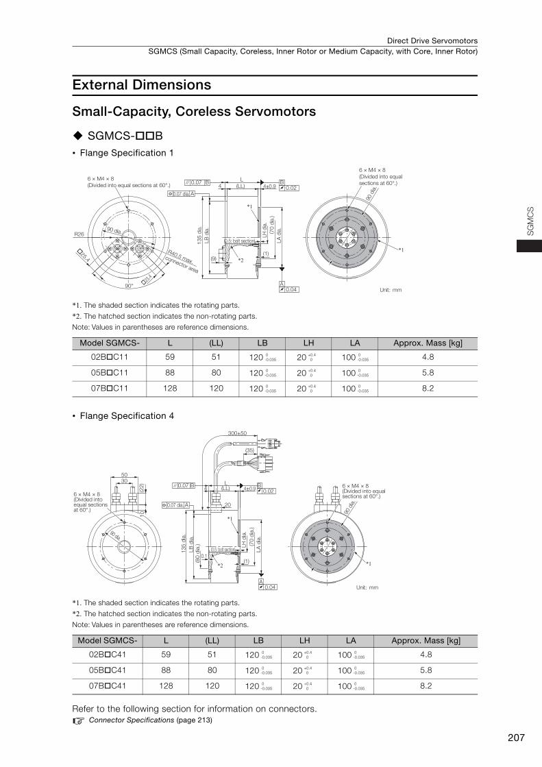
Direct Drive Servomotors SGMCS (Small Capacity, Coreless, Inner Rotor or Medium Capacity, with Core, Inner Rotor)
207
SG
MC
S
External Dimensions
Small-Capacity, Coreless Servomotors
SGMCS-B• Flange Specification 1
*1. The shaded section indicates the rotating parts.
*2. The hatched section indicates the non-rotating parts.
Note: Values in parentheses are reference dimensions.
• Flange Specification 4
*1. The shaded section indicates the rotating parts.
*2. The hatched section indicates the non-rotating parts.
Note: Values in parentheses are reference dimensions.
Refer to the following section for information on connectors. Connector Specifications (page 213)
Model SGMCS- L (LL) LB LH LA Approx. Mass [kg]
02BC11 59 51 120 20 100 4.8
05BC11 88 80 120 20 100 5.8
07BC11 128 120 120 20 100 8.2
Model SGMCS- L (LL) LB LH LA Approx. Mass [kg]
02BC41 59 51 120 20 100 4.8
05BC41 88 80 120 20 100 5.8
07BC41 128 120 120 20 100 8.2
LH
dia
.
0.04A
B0.02
A0.07 dia.
0.07 B4 (LL)
L
*1
*1
*2
4±0.9
13
5 d
ia.
LB
dia
.
(9)(1)
LA
dia
.
6 × M4 × 8
(Divided into equal
sections at 60°.)
Unit: mm
90 d
ia.
90°
R26
R40.5 max. connector area
6 × M4 × 8
(Divided into equal sections at 60°.)
90 dia.
�25.4
�23.4
( 70
dia
.)
(0.5: bolt section)
0-0.035
+0.4 0
0-0.035
0-0.035
+0.4 0
0-0.035
0-0.035
+0.4 0
0-0.035
4
20
(LL)L
(1)0.1
(35)
300±50
4±0.9
3050
6 × M4 × 8(Divided into equal sections at 60°.)
0.07 B
A0.07 dia.
13
5 d
ia.
LB
dia
.
B0.02
LA
dia
.
A0.04
*1
90 dia.
6 × M4 × 8(Divided into equal sections at 60°.)
90 d
ia.
LH
dia
.
(70
dia
.)
(80
dia
.)
*1
*2
Unit: mm
(0.5: bolt section)
(22
)1
0
0-0.035
+0.4 0
0-0.035
0-0.035
+0.4 0
0-0.035
0-0.035
+0.4 0
0-0.035
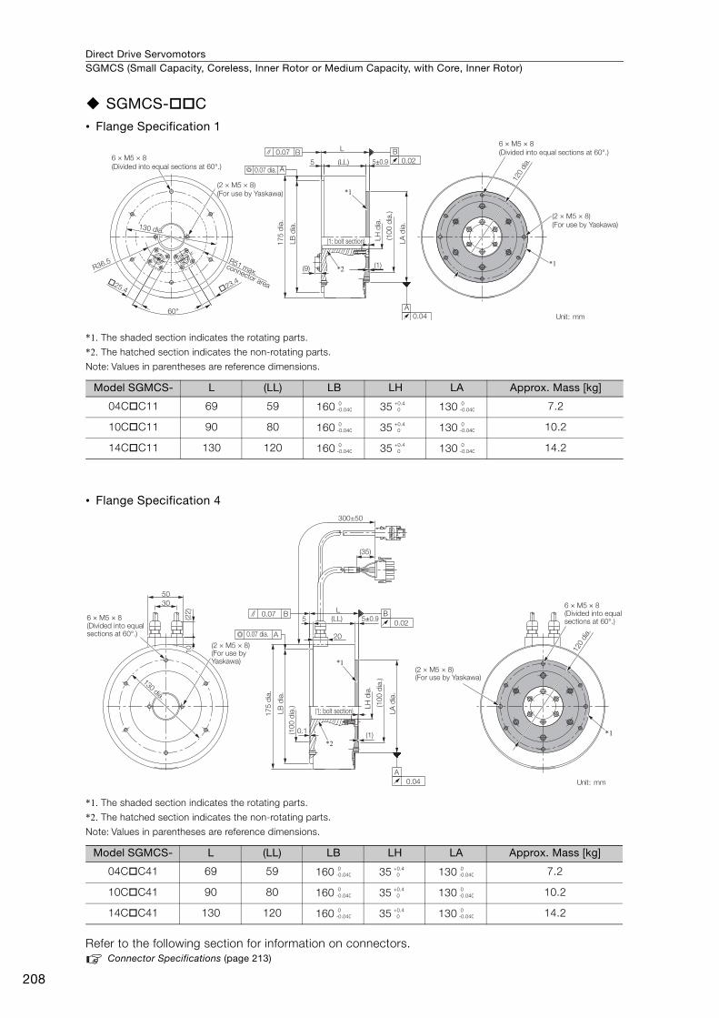
Direct Drive ServomotorsSGMCS (Small Capacity, Coreless, Inner Rotor or Medium Capacity, with Core, Inner Rotor)
208
SGMCS-C• Flange Specification 1
*1. The shaded section indicates the rotating parts.
*2. The hatched section indicates the non-rotating parts.
Note: Values in parentheses are reference dimensions.
• Flange Specification 4
*1. The shaded section indicates the rotating parts.
*2. The hatched section indicates the non-rotating parts.
Note: Values in parentheses are reference dimensions.
Refer to the following section for information on connectors. Connector Specifications (page 213)
Model SGMCS- L (LL) LB LH LA Approx. Mass [kg]
04CC11 69 59 160 35 130 7.2
10CC11 90 80 160 35 130 10.2
14CC11 130 120 160 35 130 14.2
Model SGMCS- L (LL) LB LH LA Approx. Mass [kg]
04CC41 69 59 160 35 130 7.2
10CC41 90 80 160 35 130 10.2
14CC41 130 120 160 35 130 14.2
R51 max. connector area
(2 × M5 × 8)
(For use by Yaskawa)
60°
5 (LL)
L
5±0.9
17
5 d
ia.
LB
dia
.
(9)
(1: bolt section)
*1
*2 (1)
LH
dia
.
LA
dia
.
6 × M5 × 8
(Divided into equal sections at 60°.)
120 d
ia.
(2 × M5 × 8)
(For use by Yaskawa)
*1R36.5
�25.4 �23.4
B
0.02
A0.07 dia.
0.07
0.04
A
B
(10
0 d
ia.)
6 × M5 × 8
(Divided into equal sections at 60°.)
Unit: mm
130 dia.130 dia.130 dia.
0-0.040
+0.4 0
0-0.040
0-0.040
+0.4 0
0-0.040
0-0.040
+0.4 0
0-0.040
5
20
(LL)
L
0.1
(35)
(1)
30
50
6 × M5 × 8(Divided into equal sections at 60°.)
(2 × M5 × 8)(For use by Yaskawa)
0.07 B
A
B
0.02
A
0.04
(2 × M5 × 8)(For use by Yaskawa)
6 × M5 × 8(Divided into equal sections at 60°.)
300±50
5±0.9
0.07 dia.
120 d
ia.
17
5 d
ia.
LB
dia
.
LA
dia
.
(1: bolt section)
*1
*2
LH
dia
.
(10
0 d
ia.)
(10
0 d
ia.)
*1
Unit: mm
130130 dia.
dia.
130 dia.
(22
)1
0
0-0.040
+0.4 0
0-0.040
0-0.040
+0.4 0
0-0.040
0-0.040
+0.4 0
0-0.040
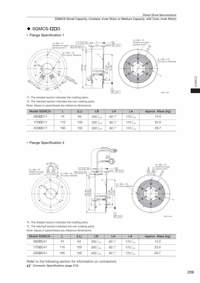
Direct Drive Servomotors SGMCS (Small Capacity, Coreless, Inner Rotor or Medium Capacity, with Core, Inner Rotor)
209
SG
MC
S
SGMCS-D• Flange Specification 1
*1. The shaded section indicates the rotating parts.
*2. The hatched section indicates the non-rotating parts.
Note: Values in parentheses are reference dimensions.
• Flange Specification 4
*1. The shaded section indicates the rotating parts.
*2. The hatched section indicates the non-rotating parts.
Note: Values in parentheses are reference dimensions.
Refer to the following section for information on connectors. Connector Specifications (page 213)
Model SGMCS- L (LL) LB LH LA Approx. Mass [kg]
08DC11 74 64 200 60 170 14.0
17DC11 110 100 200 60 170 22.0
25DC11 160 150 200 60 170 29.7
Model SGMCS- L (LL) LB LH LA Approx. Mass [kg]
08DC41 74 64 200 60 170 14.0
17DC41 110 100 200 60 170 22.0
25DC41 160 150 200 60 170 29.7
(LL)
L
5 5±0.9
(2 × M6 × 10)(For use by Yaskawa)
6 × M6 × 10(Divided into equal sections at 60°.)
60°
R67.5 max.
connector area
(2 × M6 × 10)(For use by Yaskawa)
6 × M6 × 10(Divided into equal sections at 60°.)
*1
*2(9) (1)
�25.4 �23.4
A0.08 dia.
0.08 B B
0.02
23
0 d
ia.
LB
dia
.
0.04
A
LH
dia
.
LA
dia
.
160 d
ia.
(0.5: bolt section)
(14
0 d
ia.)
*1
Unit: mm
160 dia.160 dia.160 dia.
R53
0-0.046
+0.4 0
0-0.040
0-0.046
+0.4 0
0-0.040
0-0.046
+0.4 0
0-0.040
5
20
(LL)
L
(0.5: bolt section)
0.1
(1)
5±0.9
300±50
(35)
3050
6 × M6 × 10(Divided into equal sections at 60°.) (2 × M6 × 10)
(For use by Yaskawa)
*1
*1
*2
6 × M6 × 10(Divided into equal sections at 60°.)B
0.02
0.08 B
A0.08 dia.
23
0 d
ia.
LB
dia
.
LA
dia
.
LH
dia
.
A
0.04
160 d
ia.
(14
0 d
ia.)
(14
0 d
ia.)
(2 × M6 × 10)(For use by Yaskawa)
Unit: mm
160160 dia.
dia.
160 dia.
(22
)1
0
0-0.046
+0.4 0
0-0.040
0-0.046
+0.4 0
0-0.040
0-0.046
+0.4 0
0-0.040
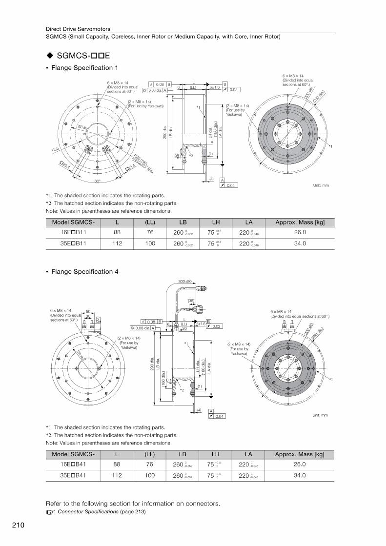
Direct Drive ServomotorsSGMCS (Small Capacity, Coreless, Inner Rotor or Medium Capacity, with Core, Inner Rotor)
210
SGMCS-E• Flange Specification 1
*1. The shaded section indicates the rotating parts.
*2. The hatched section indicates the non-rotating parts.
Note: Values in parentheses are reference dimensions.
• Flange Specification 4
*1. The shaded section indicates the rotating parts.
*2. The hatched section indicates the non-rotating parts.
Note: Values in parentheses are reference dimensions.
Refer to the following section for information on connectors. Connector Specifications (page 213)
Model SGMCS- L (LL) LB LH LA Approx. Mass [kg]
16EB11 88 76 260 75 220 26.0
35EB11 112 100 260 75 220 34.0
Model SGMCS- L (LL) LB LH LA Approx. Mass [kg]
16EB41 88 76 260 75 220 26.0
35EB41 112 100 260 75 220 34.0
60°
(2 × M8 × 14)(For use by Yaskawa)
R80 max.
connector area
*2
*1
R65
(LL)
L
6
(9) (1)
(4)
6 × M8 × 14(Divided into equal sections at 60°.)
(2 × M8 × 14)(For use by Yaskawa)
A0.08 dia.
0.08 B B
0.02
0.04
A
29
0 d
ia.
LB
dia
.
LH
dia
.
LA
dia
.
6 × M8 × 14(Divided into equal sections at 60°.)
�25.4
�23.4
200 dia.
200 d
ia.6±1.6
(18
0 d
ia.)
(280
dia.)
*1
Unit: mm
0-0.052
+0.4 0
0-0.046
0-0.052
+0.4 0
0-0.046
300±50
(35)
6 (LL)
L
0.1
(1)
(4)
*1
*1
*2
30
50
(22
)1
0
0.08 B
A
B
0.02
A
0.04
20
6±1.6
(2 × M8 × 14)
(For use by
Yaskawa)
(16
0 d
ia.)
200 d
ia.
(280
dia.)
(18
0 d
ia.)
29
0 d
ia.
0.08 dia.
(2 × M8 × 14)
(For use by
Yaskawa)
6 × M8 × 14
(Divided into equal sections at 60°.)
Unit: mm
200 dia.
6 × M8 × 14
(Divided into equal
sections at 60°.)
LB
dia
.
LA
dia
.
LH
dia
.
0-0.052
+0.4 0
0-0.046
0-0.052
+0.4 0
0-0.046
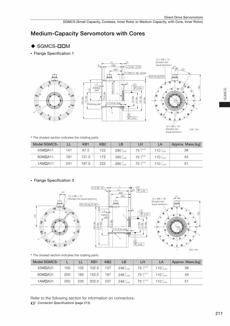
Direct Drive Servomotors SGMCS (Small Capacity, Coreless, Inner Rotor or Medium Capacity, with Core, Inner Rotor)
211
SG
MC
S
Medium-Capacity Servomotors with Cores
SGMCS-M• Flange Specification 1
* The shaded section indicates the rotating parts.
• Flange Specification 3
* The shaded section indicates the rotating parts.
Refer to the following section for information on connectors. Connector Specifications (page 213)
Model SGMCS- LL KB1 KB2 LB LH LA Approx. Mass [kg]
45MA11 141 87.5 122 280 75 110 38
80MA11 191 137.5 172 280 75 110 45
1AMA11 241 187.5 222 280 75 110 51
Model SGMCS- L LL KB1 KB2 LB LH LA Approx. Mass [kg]
45MA31 150 135 102.5 137 248 75 110 38
80MA31 200 185 152.5 187 248 75 110 45
1AMA31 250 235 202.5 237 248 75 110 51
A
15
14
7 18
2
264
dia.
41
0.04
0.04
B
0.08 dia.
15 (280 h7 dia. range)
15 (75 H6 dia. range)
A B
0.08 A B
12 × M6 × 15
(Divided into
equal sections.)
30°
KB2
KB1
LL
6
51.5
Rotating part
*
*
*
LH
dia
.
75.2
dia
.
25
0 d
ia.
28
0±
0.5
dia
.
11
5 d
ia.
LA
dia
.
14
0 d
ia.
LB
dia
.
(rotating part)
12 × M6 × 18
(Divided into
equal sections.)Unit: mm
88 dia.88 dia.88 dia.
*
0-0.052
+0.019 0
0-0.035
0-0.052
+0.019 0
0-0.035
0-0.052
+0.019 0
0-0.035
5
18
2
15LL6
KB2
KB1
L
41
1.5
0.08 C
*
*
A B0.08 dia.
LH
dia
.
11
5 d
ia.
75
.2 d
ia.
28
0 d
ia.
LA
dia
.
LB
dia
.
14
0 d
ia.
15 (75 H6 dia. range)
88 dia.
88 dia.
10°
14
7
12 × M6 × 15
(Divided into equal sections.)
264
dia
.
C
0.02
A
0.04
B
0.04
(rotating part)
*
Unit: mm
12 × M6 × 18
(Divided into
equal sections.)
88 dia.
*
0-0.046
+0.019 0
0-0.035
0-0.046
+0.019 0
0-0.035
0-0.046
+0.019 0
0-0.035
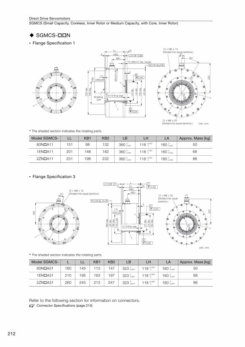
Direct Drive ServomotorsSGMCS (Small Capacity, Coreless, Inner Rotor or Medium Capacity, with Core, Inner Rotor)
212
SGMCS-N• Flange Specification 1
* The shaded section indicates the rotating parts.
• Flange Specification 3
* The shaded section indicates the rotating parts.
Refer to the following section for information on connectors. Connector Specifications (page 213)
Model SGMCS- LL KB1 KB2 LB LH LA Approx. Mass [kg]
80NA11 151 98 132 360 118 160 50
1ENA11 201 148 182 360 118 160 68
2ZNA11 251 198 232 360 118 160 86
Model SGMCS- L LL KB1 KB2 LB LH LA Approx. Mass [kg]
80NA31 160 145 113 147 323 118 160 50
1ENA31 210 195 163 197 323 118 160 68
2ZNA31 260 245 213 247 323 118 160 86
15 (360 h7 dia. range)
A
30°
344
dia.
15
LB
dia
.
16
6 d
ia.
12 × M8 × 20
(Divided into equal sections.)
15 (118 H6 dia. range)
0.04
0.04
LH
dia
.
B
19
0 d
ia.
LA
dia
.
0.08 dia. A B
0.08 A B
22
2
41
18
6
KB2
KB1
118.
2 di
a.
5
360±
0.5
dia
.
LL
32
5 d
ia.
6
12 × M8 × 15
(Divided into equal sections.)
1.5
Rotating part
(rotating part)
*
*
*
Unit: mm
135 dia.
*
0-0.057
+0.022 0
0-0.040
0-0.057
+0.022 0
0-0.040
0-0.057
+0.022 0
0-0.040
10°
22
2
41
1.5
5
LL 156
KB2
KB1
L
18
6
12 × M8 × 15
(Divided into equal sections.)
344
dia.
*
*
0.08 C C
0.02
B
0.04
A
0.04
A B0.08 dia.
11
8.2
dia
.
16
6 d
ia.
LB
dia
.
36
0 d
ia.
LH
dia
.
19
0 d
ia.
LA
dia
.
15 (118 H6 dia. range)
135 dia.
12 × M8 × 20
(Divided into equal
sections.)
(rotating part)
*
Unit: mm
*
0-0.057
+0.022 0
0-0.040
0-0.057
+0.022 0
0-0.040
0-0.057
+0.022 0
0-0.040
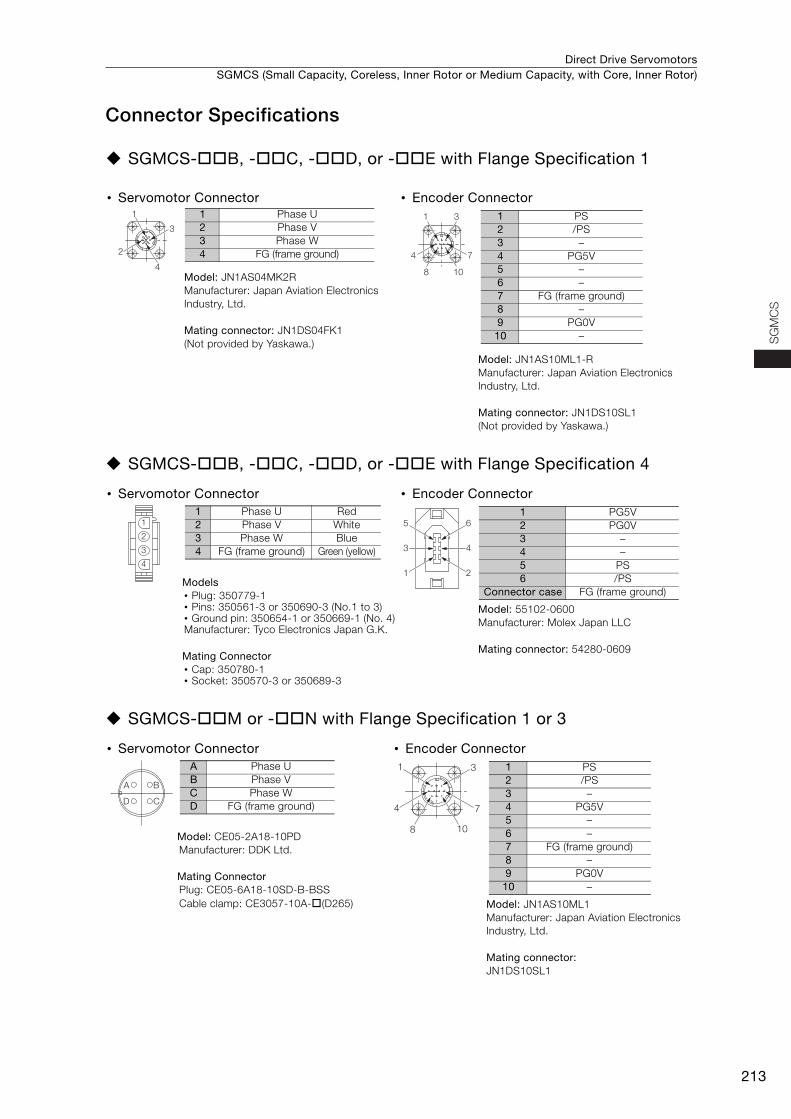
Direct Drive Servomotors SGMCS (Small Capacity, Coreless, Inner Rotor or Medium Capacity, with Core, Inner Rotor)
213
SG
MC
S
Connector Specifications
SGMCS-B, -C, -D, or -E with Flange Specification 1
SGMCS-B, -C, -D, or -E with Flange Specification 4
SGMCS-M or -N with Flange Specification 1 or 3
• Servomotor Connector • Encoder Connector
Model: JN1AS04MK2RManufacturer: Japan Aviation Electronics Industry, Ltd.
Mating connector: JN1DS04FK1 (Not provided by Yaskawa.)
Model: JN1AS10ML1-R Manufacturer: Japan Aviation Electronics Industry, Ltd.
Mating connector: JN1DS10SL1 (Not provided by Yaskawa.)
• Servomotor Connector • Encoder Connector
Models • Plug: 350779-1 • Pins: 350561-3 or 350690-3 (No.1 to 3) • Ground pin: 350654-1 or 350669-1 (No. 4) Manufacturer: Tyco Electronics Japan G.K.
Mating Connector • Cap: 350780-1 • Socket: 350570-3 or 350689-3
Model: 55102-0600Manufacturer: Molex Japan LLC
Mating connector: 54280-0609
• Servomotor Connector • Encoder Connector
Model: CE05-2A18-10PDManufacturer: DDK Ltd.
Mating Connector Plug: CE05-6A18-10SD-B-BSSCable clamp: CE3057-10A-(D265) Model: JN1AS10ML1
Manufacturer: Japan Aviation Electronics Industry, Ltd.
Mating connector: JN1DS10SL1
1
3
2
4
1 Phase U2 Phase V3 Phase W4 FG (frame ground)
1 3
4 7
8 10
1 PS2 /PS3 –4 PG5V5 –6 –7 FG (frame ground)8 –9 PG0V
10 –
1
2
3
4
1 Phase U Red2 Phase V White3 Phase W Blue4 FG (frame ground) Green (yellow) 4
2
6
3
1
5
1 PG5V2 PG0V3 –4 –5 PS6 /PS
Connector case FG (frame ground)
BA
CD
A Phase UB Phase VC Phase WD FG (frame ground)
1 3
4 7
8 10
1 PS2 /PS3 –4 PG5V5 –6 –7 FG (frame ground)8 –9 PG0V
10 –
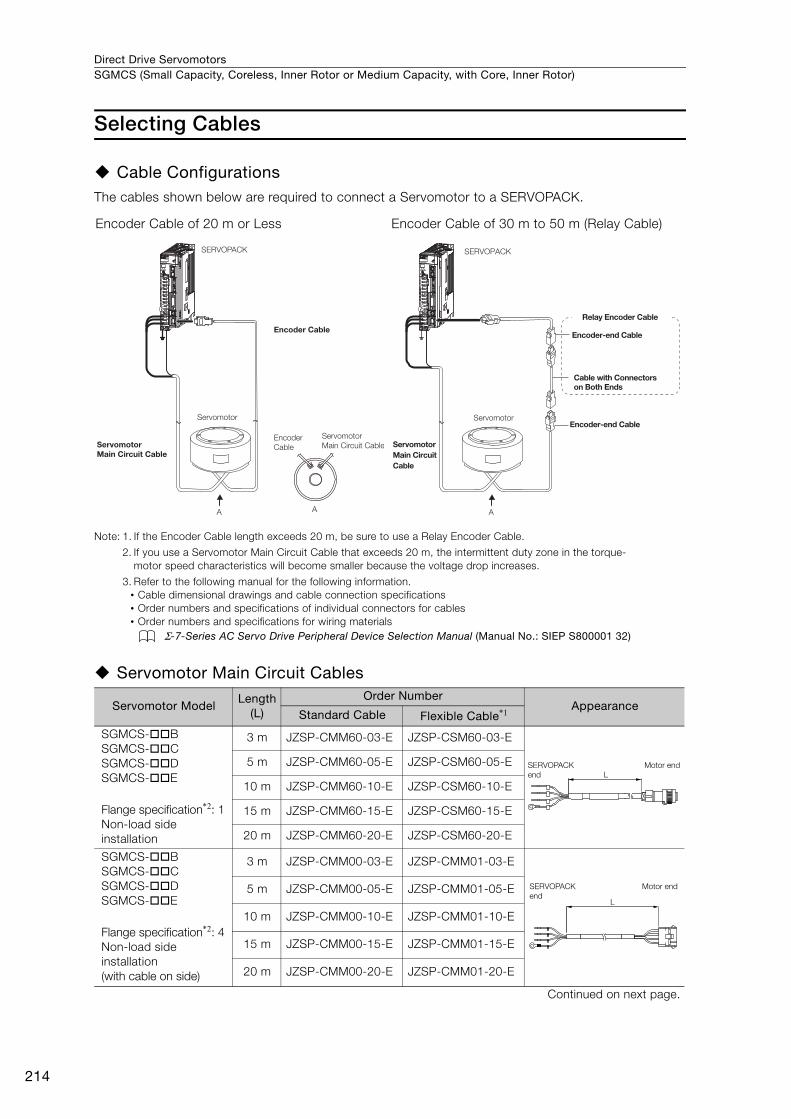
Direct Drive ServomotorsSGMCS (Small Capacity, Coreless, Inner Rotor or Medium Capacity, with Core, Inner Rotor)
214
Selecting Cables
Cable ConfigurationsThe cables shown below are required to connect a Servomotor to a SERVOPACK.
Note: 1. If the Encoder Cable length exceeds 20 m, be sure to use a Relay Encoder Cable.
2. If you use a Servomotor Main Circuit Cable that exceeds 20 m, the intermittent duty zone in the torque-motor speed characteristics will become smaller because the voltage drop increases.
3. Refer to the following manual for the following information.• Cable dimensional drawings and cable connection specifications• Order numbers and specifications of individual connectors for cables• Order numbers and specifications for wiring materials
Σ-7-Series AC Servo Drive Peripheral Device Selection Manual (Manual No.: SIEP S800001 32)
Servomotor Main Circuit Cables
Encoder Cable of 20 m or Less Encoder Cable of 30 m to 50 m (Relay Cable)
Servomotor ModelLength
(L)
Order NumberAppearance
Standard Cable Flexible Cable*1
SGMCS-BSGMCS-CSGMCS-DSGMCS-E
Flange specification*2: 1Non-load side installation
3 m JZSP-CMM60-03-E JZSP-CSM60-03-E
5 m JZSP-CMM60-05-E JZSP-CSM60-05-E
10 m JZSP-CMM60-10-E JZSP-CSM60-10-E
15 m JZSP-CMM60-15-E JZSP-CSM60-15-E
20 m JZSP-CMM60-20-E JZSP-CSM60-20-E
SGMCS-BSGMCS-CSGMCS-DSGMCS-E
Flange specification*2: 4Non-load side installation(with cable on side)
3 m JZSP-CMM00-03-E JZSP-CMM01-03-E
5 m JZSP-CMM00-05-E JZSP-CMM01-05-E
10 m JZSP-CMM00-10-E JZSP-CMM01-10-E
15 m JZSP-CMM00-15-E JZSP-CMM01-15-E
20 m JZSP-CMM00-20-E JZSP-CMM01-20-E
Continued on next page.
SERVOPACK
Encoder Cable
Encoder
Cable
Servomotor
Servomotor Main Circuit Cable
Servomotor
Main Circuit Cable
A A
SERVOPACK
Encoder-end Cable
Cable with Connectors on Both Ends
Encoder-end CableServomotor
Servomotor Main Circuit Cable
A
Relay Encoder Cable
LSERVOPACK end
Motor end
L
SERVOPACK end
Motor end
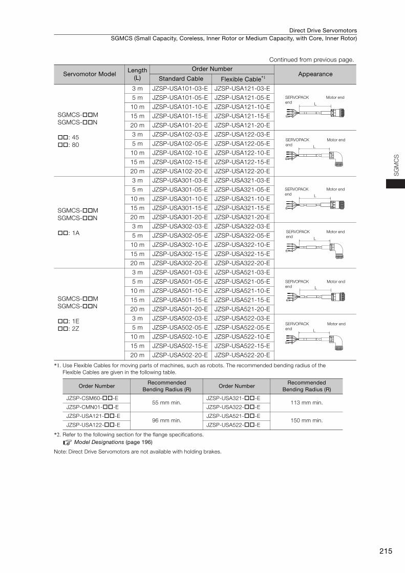
Direct Drive Servomotors SGMCS (Small Capacity, Coreless, Inner Rotor or Medium Capacity, with Core, Inner Rotor)
215
SG
MC
S
*1. Use Flexible Cables for moving parts of machines, such as robots. The recommended bending radius of the Flexible Cables are given in the following table.
*2. Refer to the following section for the flange specifications.Model Designations (page 196)
Note: Direct Drive Servomotors are not available with holding brakes.
SGMCS-MSGMCS-N
: 45: 80
3 m JZSP-USA101-03-E JZSP-USA121-03-E
5 m JZSP-USA101-05-E JZSP-USA121-05-E
10 m JZSP-USA101-10-E JZSP-USA121-10-E
15 m JZSP-USA101-15-E JZSP-USA121-15-E
20 m JZSP-USA101-20-E JZSP-USA121-20-E
3 m JZSP-USA102-03-E JZSP-USA122-03-E
5 m JZSP-USA102-05-E JZSP-USA122-05-E
10 m JZSP-USA102-10-E JZSP-USA122-10-E
15 m JZSP-USA102-15-E JZSP-USA122-15-E
20 m JZSP-USA102-20-E JZSP-USA122-20-E
SGMCS-MSGMCS-N
: 1A
3 m JZSP-USA301-03-E JZSP-USA321-03-E
5 m JZSP-USA301-05-E JZSP-USA321-05-E
10 m JZSP-USA301-10-E JZSP-USA321-10-E
15 m JZSP-USA301-15-E JZSP-USA321-15-E
20 m JZSP-USA301-20-E JZSP-USA321-20-E
3 m JZSP-USA302-03-E JZSP-USA322-03-E
5 m JZSP-USA302-05-E JZSP-USA322-05-E
10 m JZSP-USA302-10-E JZSP-USA322-10-E
15 m JZSP-USA302-15-E JZSP-USA322-15-E
20 m JZSP-USA302-20-E JZSP-USA322-20-E
SGMCS-MSGMCS-N
: 1E: 2Z
3 m JZSP-USA501-03-E JZSP-USA521-03-E
5 m JZSP-USA501-05-E JZSP-USA521-05-E
10 m JZSP-USA501-10-E JZSP-USA521-10-E
15 m JZSP-USA501-15-E JZSP-USA521-15-E
20 m JZSP-USA501-20-E JZSP-USA521-20-E
3 m JZSP-USA502-03-E JZSP-USA522-03-E
5 m JZSP-USA502-05-E JZSP-USA522-05-E
10 m JZSP-USA502-10-E JZSP-USA522-10-E
15 m JZSP-USA502-15-E JZSP-USA522-15-E
20 m JZSP-USA502-20-E JZSP-USA522-20-E
Order NumberRecommended
Bending Radius (R)Order Number
Recommended Bending Radius (R)
JZSP-CSM60--E55 mm min.
JZSP-USA321--E113 mm min.
JZSP-CMN01--E JZSP-USA322--E
JZSP-USA121--E96 mm min.
JZSP-USA521--E150 mm min.
JZSP-USA122--E JZSP-USA522--E
Continued from previous page.
Servomotor ModelLength
(L)
Order NumberAppearance
Standard Cable Flexible Cable*1
L
SERVOPACK end
Motor end
L
SERVOPACK end
Motor end
L
SERVOPACK end
Motor end
L
SERVOPACK end
Motor end
L
SERVOPACK end
Motor end
L
SERVOPACK end
Motor end
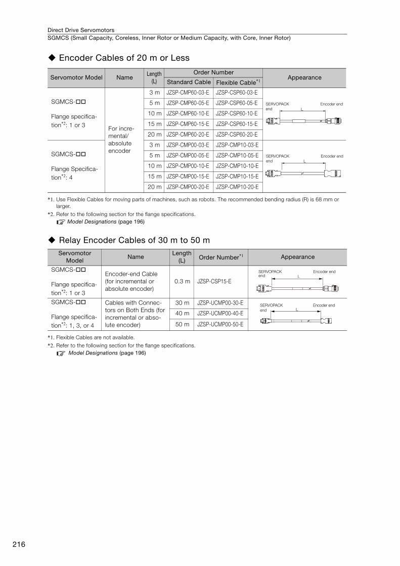
Direct Drive ServomotorsSGMCS (Small Capacity, Coreless, Inner Rotor or Medium Capacity, with Core, Inner Rotor)
216
Encoder Cables of 20 m or Less
*1. Use Flexible Cables for moving parts of machines, such as robots. The recommended bending radius (R) is 68 mm or larger.
*2. Refer to the following section for the flange specifications.Model Designations (page 196)
Relay Encoder Cables of 30 m to 50 m
*1. Flexible Cables are not available.
*2. Refer to the following section for the flange specifications.Model Designations (page 196)
Servomotor Model NameLength
(L)
Order NumberAppearance
Standard Cable Flexible Cable*1
SGMCS-
Flange specifica-tion*2: 1 or 3 For incre-
mental/absolute encoder
3 m JZSP-CMP60-03-E JZSP-CSP60-03-E
5 m JZSP-CMP60-05-E JZSP-CSP60-05-E
10 m JZSP-CMP60-10-E JZSP-CSP60-10-E
15 m JZSP-CMP60-15-E JZSP-CSP60-15-E
20 m JZSP-CMP60-20-E JZSP-CSP60-20-E
SGMCS-
Flange Specifica-tion*2: 4
3 m JZSP-CMP00-03-E JZSP-CMP10-03-E
5 m JZSP-CMP00-05-E JZSP-CMP10-05-E
10 m JZSP-CMP00-10-E JZSP-CMP10-10-E
15 m JZSP-CMP00-15-E JZSP-CMP10-15-E
20 m JZSP-CMP00-20-E JZSP-CMP10-20-E
Servomotor Model
NameLength
(L) Order Number*1 Appearance
SGMCS-
Flange specifica-tion*2: 1 or 3
Encoder-end Cable (for incremental or absolute encoder)
0.3 m JZSP-CSP15-E
SGMCS-
Flange specifica-tion*2: 1, 3, or 4
Cables with Connec-tors on Both Ends (for incremental or abso-lute encoder)
30 m JZSP-UCMP00-30-E
40 m JZSP-UCMP00-40-E
50 m JZSP-UCMP00-50-E
LSERVOPACK end
Encoder end
LSERVOPACK end
Encoder end
SERVOPACK end
Encoder endL
LSERVOPACK end
Encoder end
LITERATURE NO. KAEP S800001 23F <5>-1
16-8-16Published in Japan February 2017
In the event that the end user of this product is to be the military and said product is to
be employed in any weapons systems or the manufacture thereof, the export will fall
under the relevant regulations as stipulated in the Foreign Exchange and Foreign
Trade Regulations. Therefore, be sure to follow all procedures and submit all relevant
documentation according to any and all rules, regulations and laws that may apply.
Specifications are subject to change without notice for ongoing product modifications
and improvements.
© 2014-2017 YASKAWA ELECTRIC CORPORATION
IRUMA BUSINESS CENTER (SOLUTION CENTER)480, Kamifujisawa, Iruma, Saitama, 358-8555, Japan
Phone 81-4-2962-5151 Fax 81-4-2962-6138
http://www.yaskawa.co.jp
YASKAWA AMERICA, INC.2121, Norman Drive South, Waukegan, IL 60085, U.S.A.
Phone 1-800-YASKAWA (927-5292) or 1-847-887-7000 Fax 1-847-887-7310
http://www.yaskawa.com
YASKAWA ELÉTRICO DO BRASIL LTDA.777, Avenida Piraporinha, Diadema, São Paulo, 09950-000, Brasil
Phone 55-11-3585-1100 Fax 55-11-3585-1187
http://www.yaskawa.com.br
YASKAWA EUROPE GmbH185, Hauptstraβe, Eschborn, 65760, Germany
Phone 49-6196-569-300 Fax 49-6196-569-398
http://www.yaskawa.eu.com
YASKAWA ELECTRIC KOREA CORPORATION35F, Three IFC, 10 Gukjegeumyung-ro, Yeongdeungpo-gu, Seoul, 07326, Korea
Phone 82-2-784-7844 Fax 82-2-784-8495
http://www.yaskawa.co.kr
YASKAWA ELECTRIC (SINGAPORE) PTE. LTD.151, Lorong Chuan, #04-02A, New Tech Park 556741, Singapore
Phone 65-6282-3003 Fax 65-6289-3003
http://www.yaskawa.com.sg
YASKAWA ELECTRIC (THAILAND) CO., LTD.59, 1st-5th Floor, Flourish Building, Soi Ratchadapisek 18, Ratchadapisek Road, Huaykwang, Bangkok 10310, Thailand
Phone: +66-2-017-0099 Fax: +66-2-017-0799
http://www.yaskawa.co.th
YASKAWA ELECTRIC (CHINA) CO., LTD.22F, One Corporate Avenue, No.222, Hubin Road, Shanghai, 200021, China
Phone 86-21-5385-2200 Fax 86-21-5385-3299
http://www.yaskawa.com.cn
YASKAWA ELECTRIC (CHINA) CO., LTD. BEIJING OFFICERoom 1011, Tower W3 Oriental Plaza, No.1, East Chang An Ave.,
Dong Cheng District, Beijing, 100738, China
Phone 86-10-8518-4086 Fax 86-10-8518-4082
YASKAWA ELECTRIC TAIWAN CORPORATION9F, 16, Nanking E. Rd., Sec. 3, Taipei, 104, Taiwan
Phone 886-2-2502-5003 Fax 886-2-2505-1280
http://www.yaskawa-taiwan.com.tw
SERIES