AC or DC Operating Coil - Steven Engineering · AC or DC Operating Coil For additional information...
33
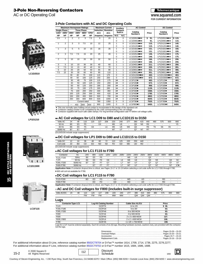
15-2 15 IEC STYLE CONTACTORS AND STARTERS I12 Discount Schedule 3/00 © 2000 Square D All Rights Reserved 3-Pole Contactors with AC and DC Operating Coils t This one normally open holding circuit contact is incorporated in the design of the standard coil. q Contactor catalog number to be completed by the code corresponding to the coil voltage. f Contactor supplied with touch safe cable clamps. For ring terminal configuration add “6” before coil voltage suffix. kk AC Coil voltages for LC1 D09 to D80 and LC1D115 to D150 (D115/D150 include surge suppression) kk DC Coil voltages for LP1 D09 to D80 and LC1D115 to D150 (D115/D150 include surge suppression) k AC Coil voltages for LC1 F115 to F780 Application Note: If contactor dropout time is critical, see Pages 15-17 or 15-19 before selecting a coil code suffix for LC1 F265 through F780. f 600 volt coil not available for F780. k DC Coil voltages for LC1 F115 to F780 Application Note: If contactor dropout time is critical, see Pages 15-17 or 15-19 before selecting a coil code suffix for LC1 F265 through F780. d AC and DC Coil voltages for F800 (includes built-in surge suppressor) Lugs Lugs for LC1F must be ordered separately. Each kit consists of six (6) lugs. Mounting hardware (screws, washers nuts,) are provided with the contactor, not the lugs. Maximum Horsepower Ratings Maximum Current Auxiliary Contacts Built In AC Control DC Control Single Phase Three Phase Inductive Resistive Catalog Numberq Price Catalog Numberq Price 115V 230V 200V 230V 460V 575V AC3 AC1 HP HP HP HP HP HP Amperes Amperes N.O. N.C. 0.5 1 2 2 5 7.5 9 20 1 0 LC1D0910kk f $ 91. LP1D0910kk f $ 115. 0 1 LC1D0901kk f 91. LP1D0901kk f 115. 1 2 3 3 7.5 10 12 25 1 0 LC1D1210kk f 115. LP1D1210kk f 140. 0 1 LC1D1201kk f 115. LP1D1201kk f 140. 1 3 5 5 10 15 18 35 1 0 LC1D1810kk f 131. LP1D1810kk f 155. 0 1 LC1D1801kk f 131. LP1D1801kk f 155. 2 3 7.5 7.5 15 20 25 40 1 0 LC1D2510kk f 146. LP1D2510kk f 175. 0 1 LC1D2501kk f 146. LP1D2501kk f 175. 2 5 10 10 20 30 32 50 1 0 LC1D3210kk f 166. LP1D3210kk f 206. 0 1 LC1D3201kk f 166. LP1D3201kk f 206. 3 5 10 10 30 30 40 60 1 1 LC1D4011kk f 211. LP1D4011kk f 266. 3 7.5 15 15 40 40 50 70 1 1 LC1D5011kk f 226. LP1D5011kk f 281. 5 10 20 20 50 50 65 80 1 1 LC1D6511kk f 311. LP1D6511kk f 366. 7.5 15 30 30 60 60 80 110 1 1 LC1D8011kk f 351. LP1D8011kk f 406. 30 40 75 100 115 175 0 0 LC1D11500kk f 463. LC1D11500kk f 463. 40 50 100 125 150 200 0 0 LC1D15000kk f 672. LC1D15000kk f 672. 30 40 75 100 115 175 1t 0 LC1F115k 463. LC1F115k 463. 40 50 100 125 150 200 1t 0 LC1F150k 672. LC1F150k 672. 50 60 125 150 185 200 1t 0 LC1F185k 906. LC1F185k 906. 60 75 150 175 265 285 1t 0 LC1F265k 1139. LC1F265k 1139. 75 100 200 250 330 360 1t 0 LC1F330k 1566. LC1F330k 1566. 100 125 250 300 400 420 1t 0 LC1F400k 1785. LC1F400k 1785. 150 200 400 500 500 700 1t 0 LC1F500k 4802. LC1F500k 4802. 250 300 600 800 630 1000 1t 0 LC1F630k 6640. LC1F630k 6640. Current rated 780 1350 0 0 LC1F780k 7525. LC1F780k 7525. — 450 800 900 800 1000 0 0 LC1F800kd 6450. LC1F800kd 6450. Volts AC 24 48 110 120 127 208 220 240 277 380 415 440 480 575 600 660 50 Hz B5 E5 F5 - G5 - M5 U5 - Q5 N5 R5 - - - Y5 60 Hz B6 E6 F6 G6 - L6 M6 U6 W6 Q6 R6 T6 S6 X6 - 50/60 Hz B7 E7 F7 - - - M7 U7 - Q7 N7 R7 - - - - Volts DC 12 24 36 48 60 72 110 125 220 250 440 - - - - - Coil code JD BD CD ED ND SD FD GD MD UD RD - - - - - Contactor Hz 24V 48V 110V 120V 125V 208V 220V 240V 250V 380V 415V 440V 480V 600V F115, F150 F185 50Hz B5 E5 F5 - - - M5 U5 - Q5 - - - - 60 Hz B6 E6 F6 G6 - L6 M6 U6 - Q6 N5 - Q5 SC F265, F330 50/60 Hz B7 E7 F7 G7 - L7 M7 U7 - Q7 Q7 - S7 X7 F400-F780 50/60 Hz - E7 F7 F7 - L7 M7 U7 - Q7 N7 - N7 X7f F115-F330 - BD ED FD - GD - MD - UD - - RD - - F400-F780 - - ED FD - GD - MD - UD - - RD - - Volts AC/DC 24 48 110 120 127 208 220 240 277 380 415 440 480 575 600 660 - - FW FW FW - MW MW - QW QW QW - - - - Contactor Type LC1 Lug Kit Catalog Number Cable Size AL/CU Price F115 DZ2FF6 14 to 2/0 $ 38. F150, F185 DZ2FG6 6 to 3/0 63. F265, F330 DZ2FH6 6 to 300 MCM 63. F400 DZ2FJ6 4 to 500 MCM 63. F500 DZ2FK6 2 x 2 x 600 MCM 127. F630, F800 DZ2FL6 2 x 2 x 600 MCM 158. F780 DZ2FX6 1 x 1/0 x 750 MCM 158. LC1D2510 LC1F115 3-Pole Non-Reversing Contactors AC or DC Operating Coil For additional information about D-Line, reference catalog number 8502CT9704 or D-Fax™ number 1614, 1709, 1714, 1736, 2275, 2276,2277. For additional information about F-Line, reference catalog number 8502CT9702 or D-Fax™ number 1615, 1684, 1686, 1688. LP1D1210 Dimensions. . . . . . . . . . . . . . . . . . . . . . . . . . . . . . . . . . . . . . . . . . . . . . . . . . Pages 15-26 – 15-33 Overload Relays . . . . . . . . . . . . . . . . . . . . . . . . . . . . . . . . . . . . . . . . . . . . . . Pages 15-20 – 15-21 Accessories . . . . . . . . . . . . . . . . . . . . . . . . . . . . . . . . . . . . . . . . . . . . . . . . . . Pages 15-7 – 15-15 Replacement Coils . . . . . . . . . . . . . . . . . . . . . . . . . . . . . . . . . . . . . . . . . . . . Pages 15-16 – 15-19 LC1D11500 Courtesy of Steven Engineering, Inc. ! 230 Ryan Way, South San Francisco, CA 94080-6370 ! Main Office: (650) 588-9200 ! Outside Local Area: (800) 258-9200 ! www.stevenengineering.com
Transcript of AC or DC Operating Coil - Steven Engineering · AC or DC Operating Coil For additional information...
15-2
15
IEC
ST
YL
E C
ON
TA
CT
OR
S
AN
D S
TA
RT
ER
S
I
12 DiscountSchedule
3/00
© 2000 Square DAll Rights Reserved
3-Pole Contacto rs with AC and DC Operating Coils
t
This one normally open holding circuit contact is incorporated in the design of the standard coil.
q
Contactor catalog number to be completed by the code corresponding to the coil voltage.
f
Contactor supplied with touch safe cable clamps. For ring terminal configuration add “6” before coil voltage suffix.
kk
AC Coil voltages for LC1 D09 to D80 and LC1D115 to D150
(D115/D150 include surge suppression)
kk
DC Coil voltages for LP1 D09 to D80 and LC1D115 to D150
(D115/D150 include surge suppression)
k
AC Coil voltages for LC1 F115 to F780
Application Note:
If contactor dropout time is critical, see Pages 15-17 or 15-19 before selecting a coil code suffix for LC1 F265 through F780.
f
600 volt coil not available for F780.
k
DC Coil voltages for LC1 F115 to F780
Application Note:
If contactor dropout time is critical, see Pages 15-17 or 15-19 before selecting a coil code suffix for LC1 F265 through F780.
d
AC and DC Coil voltages for F800 (in cludes built-in su rge suppressor)
Lugs
Lugs for LC1F must be ordered separately. Each kit consists of six (6) lugs. Mounting hardware (screws, washers nuts,) are provided with the contactor,not the lugs.
Maximum Horsepower Ratings Maximum Current AuxiliaryContactsBuilt In
AC Cont rol DC Cont rolSingle Phase Three Phase Inductiv e Resistive
CatalogNumber
q
Price CatalogNumber
q
Price115V 230V 200V 230V 460V 575V AC3 AC1HP HP HP HP HP HP Ampere s Amperes N.O. N.C.
0.5 1 2 2 5 7.5 9 20 1 0 LC1D0910
kk f
$ 91.
LP1D0910
kk f
$ 115.
0 1 LC1D0901
kk f
91.
LP1D0901
kk f
115.
1 2 3 3 7.5 10 12 25 1 0 LC1D1210
kk f
115.
LP1D1210
kk f
140.
0 1 LC1D1201
kk f
115.
LP1D1201
kk f
140.
1 3 5 5 10 15 18 35 1 0 LC1D1810
kk f
131.
LP1D1810
kk f
155.
0 1 LC1D1801
kk f
131.
LP1D1801
kk f
155.
2 3 7.5 7.5 15 20 25 40 1 0 LC1D2510
kk f
146.
LP1D2510
kk f
175.
0 1 LC1D2501
kk f
146.
LP1D2501
kk f
175.
2 5 10 10 20 30 32 50 1 0 LC1D3210
kk f
166.
LP1D3210
kk f
206.
0 1 LC1D3201
kk f
166.
LP1D3201
kk f
206.
3 5 10 10 30 30 40 60 1 1 LC1D4011
kk f
211.
LP1D4011
kk f
266.
3 7.5 15 15 40 40 50 70 1 1 LC1D5011
kk f
226.
LP1D5011
kk f
281.
5 10 20 20 50 50 65 80 1 1 LC1D6511
kk f
311.
LP1D6511
kk f
366.
7.5 15 30 30 60 60 80 110 1 1 LC1D8011
kk f
351.
LP1D8011
kk f
406.
30 40 75 100 115 175 0 0 LC1D11500
kk f
463.
LC1D11500
kk f
463.
40 50 100 125 150 200 0 0 LC1D15000
kk f
672.
LC1D15000
kk f
672.
30 40 75 100 115 175 1
t
0 LC1F115
k
463.
LC1F115
k
463.
40 50 100 125 150 200 1
t
0 LC1F150
k
672.
LC1F150
k
672.
50 60 125 150 185 200 1
t
0 LC1F185
k
906.
LC1F185
k
906.
60 75 150 175 265 285 1
t
0 LC1F265
k
1139.
LC1F265
k
1139.
75 100 200 250 330 360 1
t
0 LC1F330
k
1566.
LC1F330
k
1566.
100 125 250 300 400 420 1
t
0 LC1F400
k
1785.
LC1F400
k
1785.
150 200 400 500 500 700 1
t
0 LC1F500
k
4802.
LC1F500
k
4802.
250 300 600 800 630 1000 1
t
0 LC1F630
k
6640.
LC1F630
k
6640.
Current rated 780 1350 0 0 LC1F780
k
7525.
LC1F780
k
7525.
— 450 800 900 800 1000 0 0 LC1F800
kd
6450.
LC1F800
kd
6450.
Volts AC 24 48 110 120 127 208 220 240 277 380 415 440 480 575 600 66050 Hz B5 E5 F5 - G5 - M5 U5 - Q5 N5 R5 - - - Y560 Hz B6 E6 F6 G6 - L6 M6 U6 W6 Q6 R6 T6 S6 X6 -
50/60 Hz B7 E7 F7 - - - M7 U7 - Q7 N7 R7 - - - -
Volts DC 12 24 36 48 60 72 110 125 220 250 440 - - - - -Coil code JD BD CD ED ND SD FD GD MD UD RD - - - - -
Contactor Hz 24V 48V 110V 120V 125V 208V 220V 240V 250V 380V 415V 440V 480V 600V
F115, F150F185
50Hz B5 E5 F5 - - - M5 U5 - Q5 - - - -60 Hz B6 E6 F6 G6 - L6 M6 U6 - Q6 N5 - Q5 SC
F265, F330 50/60 Hz B7 E7 F7 G7 - L7 M7 U7 - Q7 Q7 - S7 X7F400-F780 50/60 Hz - E7 F7 F7 - L7 M7 U7 - Q7 N7 - N7 X7
f
F115-F330 - BD ED FD - GD - MD - UD - - RD - -F400-F780 - - ED FD - GD - MD - UD - - RD - -
Volts AC/DC 24 48 110 120 127 208 220 240 277 380 415 440 480 575 600 660 - - FW FW FW - MW MW - QW QW QW - - - -
Contacto r Type LC1 Lug Kit Catalog Number Cable Size AL/CU Price
F115 DZ2FF6 14 to 2/0
$ 38.
F150, F185 DZ2FG6 6 to 3/0
63.
F265, F330 DZ2FH6 6 to 300 MCM
63.
F400 DZ2FJ6 4 to 500 MCM
63.
F500 DZ2FK6 2 x 2 x 600 MCM
127.
F630, F800 DZ2FL6 2 x 2 x 600 MCM
158.
F780 DZ2FX6 1 x 1/0 x 750 MCM
158.
LC1D2510
LC1F115
3-Pole Non-Reversing Contactors
AC or DC Operating Coil
For additional information about D-Line, reference catalog number 8502CT9704 or D-Fax™ number 1614, 1709, 1714, 1736, 2275, 2276,2277.For additional information about F-Line, reference catalog number 8502CT9702 or D-Fax™ number 1615, 1684, 1686, 1688.
LP1D1210
Dimensions. . . . . . . . . . . . . . . . . . . . . . . . . . . . . . . . . . . . . . . . . . . . . . . . . . Pages 15-26 – 15-33Overload Relays. . . . . . . . . . . . . . . . . . . . . . . . . . . . . . . . . . . . . . . . . . . . . . Pages 15-20 – 15-21Accessories . . . . . . . . . . . . . . . . . . . . . . . . . . . . . . . . . . . . . . . . . . . . . . . . . . Pages 15-7 – 15-15Replacement Coils . . . . . . . . . . . . . . . . . . . . . . . . . . . . . . . . . . . . . . . . . . . . Pages 15-16 – 15-19
LC1D11500
Courtesy of Steven Engineering, Inc. ! 230 Ryan Way, South San Francisco, CA 94080-6370 ! Main Office: (650) 588-9200 ! Outside Local Area: (800) 258-9200 ! www.stevenengineering.com
15-3
I
12 DiscountSchedule
3/00
15
IEC
ST
YL
E C
ON
TA
CT
OR
SA
ND
ST
AR
TE
RS
© 2000 Square DAll Rights Reserved
Dimensions . . . . . . . . . . . . . . . . . . . . . . . . . . . . . . . . . . . . . . . . . . . . . . . . . .Pages 15-26 – 15-33Overload Relays. . . . . . . . . . . . . . . . . . . . . . . . . . . . . . . . . . . . . . . . . . . . . . .Pages 15-20 – 15-21Accessories . . . . . . . . . . . . . . . . . . . . . . . . . . . . . . . . . . . . . . . . . . . . . . . . . . .Pages 15-7 – 15-15Replacement Coils. . . . . . . . . . . . . . . . . . . . . . . . . . . . . . . . . . . . . . . . . . . . .Pages 15-16 – 15-19
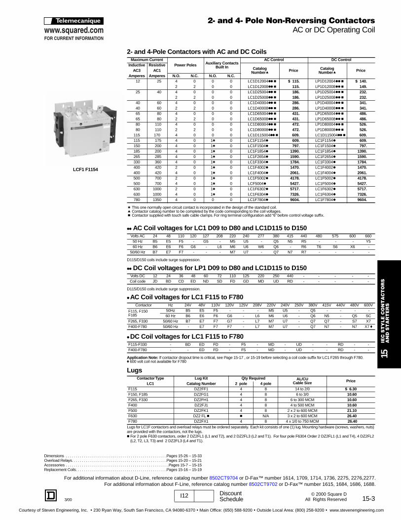
2- and 4-Pole Contacto rs with AC and DC Coils
t
This one normally open circuit contact is incorporated in the design of the standard coil.
q
Contactor catalog number to be completed by the code corresponding to the coil voltages.
c
Contactor supplied with touch safe cable clamps. For ring terminal configuration add “6” before control voltage suffix.
kk
AC Coil voltages for LC1 D09 to D80 and LC1D115 to D150
D115/D150 coils include surge suppression.
kk
DC Coil voltages for LP1 D09 to D80 and LC1D115 to D150
D115/D150 coils include surge suppression.
k
AC Coil voltages for LC1 F115 to F780
k
DC Coil voltages for LC1 F115 to F780
Application Note:
If contactor dropout time is critical, see Page 15-17 , or 15-19 before selecting a coil code suffix for LC1 F265 through F780.
f
600 volt coil not available for F780
Lugs
Lugs for LC1F contactors and overload relays must be ordered separately. Each kit consists of one (1) lug. Mounting hardware (screws, washers, nuts) are provided with the contactors, not the lugs.
c
For 2 pole F630 contactors, order 2 DZ2FL1 (L1 and T2), and 2 DZ2FL3 (L2 and T1). For four pole F6304 Order 2 DZ2FL1 (L1 and T4), 4 DZ2FL2 (L2, T2, L3, T3) and 2 DZ2FL3 (L4 and T1).
Maximum CurrentPower Poles Auxiliary Contacts
Built In
AC Cont rol DC Cont rolInductiv e Resistive
CatalogNumber
q
Price CatalogNumber
q
Pric eAC3 AC1Amperes Amperes N.O. N.C. N.O. N.C.
12 25 4 0 0 0 LC1D12004
kk c
$ 115.
LP1D12004
kk c
$ 140.
2 2 0 0 LC1D12008
kk c
115.
LP1D12008
kk c
149.
25 40 4 0 0 0 LC1D25004
kk c
186. LP1D25004kk c 232.2 2 0 0 LC1D25008kk c 186. LP1D25008kk c 232.
40 60 4 0 0 0 LC1D40004kk c 286. LP1D40004kk c 341.40 60 2 2 0 0 LC1D40008kk c 286. LP1D40008kk c 341.65 80 4 0 0 0 LC1D65004kk c 431. LP1D65004kk c 486.65 80 2 2 0 0 LC1D65008kk c 431. LP1D65008kk c 486.80 110 4 0 0 0 LC1D80004kk c 472. LP1D80004kk c 526.80 110 2 2 0 0 LC1D80008kk c 472. LP1D80008kk c 526.
115 170 4 0 0 0 LC1D115004kk c 609. LC1D115004kk c 609.115 175 4 0 1t 0 LC1F1154k 609. LC1F1154k 609.150 200 4 0 1t 0 LC1F1504k 797. LC1F1504k 797.185 200 4 0 1t 0 LC1F1854k 1390. LC1F1854k 1390.265 285 4 0 1t 0 LC1F2654k 1590. LC1F2654k 1590.330 360 4 0 1t 0 LC1F3304k 1784. LC1F3304k 1784.400 420 2 0 1t 0 LC1F4002k 1470. LC1F4002k 1470.400 420 4 0 1t 0 LC1F4004k 2061. LC1F4004k 2061.500 700 2 0 1t 0 LC1F5002k 4178. LC1F5002k 4178.500 700 4 0 1t 0 LCF5004k 5427. LC1F5004k 5427.630 1000 2 0 1t 0 LC1F6302k 5717. LC1F6302k 5717.630 1000 4 0 1t 0 LC1F6304k 7326. LC1F6304k 7326.780 1350 4 0 0 0 LC1F7804k 9604. LC1F7804k 9604.
Volts AC 24 48 110 120 127 208 220 240 277 380 415 440 480 575 600 66050 Hz B5 E5 F5 - G5 - M5 U5 - Q5 N5 R5 - - - Y560 Hz B6 E6 F6 G6 - L6 M6 U6 W6 Q6 - R6 T6 S6 X6 -
50/60 Hz B7 E7 F7 - - - M7 U7 - Q7 N7 R7 - - - -
Volts DC 12 24 36 48 60 72 110 125 220 250 440 - - - - -Coil code JD BD CD ED ND SD FD GD MD UD RD - - - - -
Contactor Hz 24V 48V 110V 120V 125V 208V 220V 240V 250V 380V 415V 440V 480V 600V
F115, F150F185
50Hz B5 E5 F5 - - - M5 U5 - Q5 - - - -60 Hz B6 E6 F6 G6 - L6 M6 U6 - Q6 N5 - Q5 SC
F265, F330 50/60 Hz B7 E7 F7 G7 - L7 M7 U7 - Q7 Q7 - S7 X7F400-F780 50/60 Hz - E7 F7 F7 - L7 M7 U7 - Q7 N7 - N7 X7 f
F115-F330 - BD ED FD - F5 - MD - UD - - RD - -F400-F780 - - ED FD - F5 - MD - UD - - RD - -
Contacto r Type Lug Kit Qty Required AL/CUCable Size Price
LC1 Catalog Number 2 pole 4 poleF115 DZ2FF1 4 8 14 to 2/0 $ 6.30F150, F185 DZ2FG1 4 8 6 to 3/0 10.60F265, F330 DZ2FH1 4 8 6 to 300 MCM 10.60F400 DZ2FJ1 4 8 4 to 500 MCM 10.60F500 DZ2FK1 4 8 2 x 2 to 600 MCM 21.10F630 DZ2 FL c c N/A 3 x 2 to 600 MCM 26.40F780 DZ2FX1 4 8 4 x 1/0 to 750 MCM 26.40
LCF1 F1154
2- and 4- Pole Non-Reversing ContactorsAC or DC Operating Coil
For additional information about D-Line, reference catalog number 8502CT9704 or D-Fax™ number 1614, 1709, 1714, 1736, 2275, 2276,2277.For additional information about F-Line, reference catalog number 8502CT9702 or D-Fax™ number 1615, 1684, 1686, 1688.
Courtesy of Steven Engineering, Inc. ! 230 Ryan Way, South San Francisco, CA 94080-6370 ! Main Office: (650) 588-9200 ! Outside Local Area: (800) 258-9200 ! www.stevenengineering.com

15-4
15IE
C S
TY
LE
CO
NT
AC
TO
RS
A
ND
ST
AR
TE
RS
I12 DiscountSchedule 3/00
© 2000 Square DAll Rights Reserved
Dimensions. . . . . . . . . . . . . . . . . . . . . . . . . . . . . . . . . . . . . . . . . . . . . . . . . . .Page 15-26 — 15-33Overload Relays. . . . . . . . . . . . . . . . . . . . . . . . . . . . . . . . . . . . . . . . . . . . . . . . . . . . . . Page 15-21Accessories . . . . . . . . . . . . . . . . . . . . . . . . . . . . . . . . . . . . . . . . . . . . . . . . . . .Pages 15-7 – 15-15Replacement Coils. . . . . . . . . . . . . . . . . . . . . . . . . . . . . . . . . . . . . . . . . . . . Pages 15-16 – 15-19
3-Pole Mechanical ly Interlo cked Contacto rsEach device is pre-wired with line and load side power wiring for reversing applications.
t These two normally closed contacts are incorporated in the design of the mechanical interlock.f Contactors supplied with touch safe cable clamps. For ring terminal configuration, add “6” before coil voltage suffix.
4-Pole Mechanical ly Interlo cked Contacto rsEach device is pre-wired with load side power wiring.
If electrical interlocking is required, a separate auxiliary contact block with a N.C. contact will have to be added to each contactor.f Contactors supplied with touch safe cable clamps. For ring terminal configuration, add “6” before coil voltage suffix.
kk AC Coil voltages for LC2 D09 to D80 and LC2D115 to D150 q
kk DC Coil voltages for LP2 D09 to D32 and LC2D115 to D150 q
c Contactor catalog number to be completed by the code corresponding to the coil voltage. q D115/D150 coils include surge suppression.
Maximum Horsepower Ratings Maximum Current Built InAuxiliaryContacts
(per contactor)
AC Cont rol DC Cont rol
Single Phase Three Phase Inductiv e Resistive CatalogNumber c f Price Catalog
Number c f Price115V 230V 200V 230V 460V 575V AC3 AC1
HP HP HP HP HP HP Amperes Amperes N.O. N.C.
0.5 1 2 2 5 7.5 9 20 0 1 LC2D0901kk $ 226. LP2D0901kk $306.
1 2t LC2D0911kk 239.
1 2 3 3 7.5 10 12 25 0 1 LC2D1201kk 306. LP2D1201kk 356.
1 2t LC2D1211kk 320.
1 3 5 5 10 15 18 35 0 1 LC2D1801kk 332. LP2D1801kk 386.
1 2t LC2D1811kk 348.
2 3 7.5 7.5 15 20 25 40 0 1 LC2D2501kk 361. LP2D2501kk 421.
1 2t LC2D2511kk 375.
2 5 10 10 20 30 32 50 0 1 LC2D3201kk 401. LP2D3201kk 486.
1 2t LC2D3211kk 415.
3 5 10 10 30 30 40 60 1 1 LC2D4011kk 546.
3 7.5 15 15 40 40 50 70 1 1 LC2D5011kk 576.
5 10 20 20 50 50 65 80 1 1 LC2D6511kk 752.
7.5 15 30 30 60 60 80 110 1 1 LC2D8011kk 1113.
— — 30 40 75 100 115 175 0 0 LC2D11500kk 1126. LC2D11500kk 1126.
— — 40 50 100 125 150 200 0 0 LC2D15000kk 12544. LC2D15000kk 1544.
Maximum Ho rsepower Ratings Maximum Current Built InAuxiliaryContacts
(per contacto rs)
AC Cont rol DC Cont rol
Single Phase Three Phase Inductiv e Resistive CatalogNumber c Price Catalog
Number c Price115V 230V 200V 230V 460V 575V AC3 AC1
HP HP HP HP HP HP Ampere s Amperes N.O. N.C.
1 2 3 3 7.5 10 12 25 0 0 LC2D12004kk $ 306. LP2D12004kk $356.
2 3 7.5 7.5 15 20 25 40 0 0 LC2D25004kk 441. LP2D25004kk 461.
3 5 10 10 30 30 40 60 0 0 LC2D40004kk 696. - -
5 10 20 20 50 50 65 80 0 0 LC2D65004kk 1315. - -
7.5 15 25 30 60 60 80 110 0 0 LC2D80004kk 1358. - -
— — 30 40 75 100 115 175 0 0 LC2D11500kk f 1344. LC2D11500kk f 1344.
Volts AC 24 110 120 127 208 220 240 277 380 415 440 480 575 600 660
50 Hz B5 F5 - G5 - M5 U5 - Q5 N5 R5 - - - Y5
60 Hz B6 F6 G6 - L6 M6 U6 W6 Q6 - R6 T6 S6 X6 -
50/60 Hz B7 F7 - - - M7 U7 - Q7 N7 R7 - - - -
Volts DC 12 24 48 72 110 125 220 250
Coil Code JD BD ED SD FD GD MD UD
LC2D0901G6
3- and 4-Pole Reversing ContactorsAC or DC Operating Coil
For additional information about D-Line, reference catalog number 8502CT9704 or D-Fax™ number 1614, 1709, 1714, 1736, 2275, 2276,2277.
Courtesy of Steven Engineering, Inc. ! 230 Ryan Way, South San Francisco, CA 94080-6370 ! Main Office: (650) 588-9200 ! Outside Local Area: (800) 258-9200 ! www.stevenengineering.com

15-5I12 DiscountSchedule3/00
15IE
C S
TY
LE
CO
NT
AC
TO
RS
AN
D S
TA
RT
ER
S
© 2000 Square DAll Rights Reserved
HOW TO ORDER:Components are available for customer assembly of F-line reversing contactors. For example, the followingcomponents must be ordered to build a 75-HP @ 460 V reversing contactor with a 120 V/60 Hz coil:
c Contactor catalog number to be completed by the code corresponding to the coil voltage.Application Note : If contactor dropout time is critical, see Page 15-17 or 15-19 before selecting a coil code suffix for LC1 F265 through F780.
Coil voltages for LC1 F115 to F780
a 600 volt coil not available for F780.See Page 15-3 for DC coil voltage codes.
f For two different size contactors, refer to pages 15-14, 15
Quantity2 LC1F115G6 Contactors 2 x $463.00
6 DZ2FF1 Lugs (page 15-3) 6 x 6.30
2 LA1DN11 Auxiliary contacts 2 x 20.00
1 LA9FF976 Power connections 1 x 102.00
1 LA9FF970 Mechanical interlock 1 x 50.80
3-Pole Contacto rsMaximum Ho rsepower Ratings Maximum Current Holding Ci rcuit
contact builtinto coil
CatalogNumber c Price
Three Phase Inductive Resistive
200 V 230 V 460 V 575 V AC3 AC1
HP HP HP HP Amperes Amperes N.O. N.C.
30 40 75 100 115 175 1 0 LC1F115 $ 463.
40 50 100 125 150 200 1 0 LC1F150 672.
50 60 125 150 185 200 1 0 LC1F185 906.
60 75 150 200 265 285 1 0 LC1F265 1139.
75 100 200 250 330 360 1 0 LC1F330 1566.
100 125 250 300 400 420 1 0 LC1F400 1785.
150 200 400 500 500 700 1 0 LC1F500 4802.
250 300 600 800 630 1000 1 0 LC1F630 6640.
Current rated 780 1350 0 0 LC1F780 7525.
— 450 800 900 800 1000 0 0 LC1F800 7150.
Contactor Hz 24 V 48 V 110 V 120 V 208 V 220 V 240 V 380 V 415 V 480 V 600 V
F115, F150 50 Hz B5 E5 F5 - M5 U5 Q5 - - - -
F185 60 Hz B6 E6 F6 G6 L6 M6 U6 Q6 N5 Q5 SC
F265, F330 50/60 Hz B7 E7 F7 G7 L7 M7 U7 Q7 Q7 S7 X7
F400 - F780 50/60 Hz – E7 F7 F7 L7 M7 U7 Q7 N7 N7 X7 a
Auxiliary contact (electrical interlo cking) - 2 must be pu rchased
For use withNumber
ofcontacts
Maximum numberof blo cks
per contactor
Contactarrangement Catalog
Number PriceN.O. N.C.
LC1 Fto be ordered
separately
1 1 1 - LA1DN10 $12.70- 1 LA1DN01 12.70
2 2 1 1 LA1DN11 20.002 - LA1DN20 20.00
4 2 2 2 LA1DN22 40.101 3 LA1DN13 40.104 - LA1DN40 40.10- 4 LA1DN04 40.103 1 LA1DN31 40.10
(2) including 1 N.O. + 1 N.C. make-before-break 2 2 (2) LA1DC22 40.10
AccessoriesFor the assembly of three-pole reversing contactors
With 2 identical
contacto rs f
Set of p ower connectionscatalog number Price
Horizontal mountingMechanical interlo ckKit catalog number
Price
LC1F115 LA9FF976 $ 93.00 LA9FF970 $46.40
LC1F150 LA9F15076 93.00 LA9FF970 46.40
LC1F185 LA9FG976 99.00 LA9FG970 46.40
LC1F265 LA9FH976 146.00 LA9FJ970 66.00
LC1F330 LA9FJ976 198.00 LA9FJ970 66.00
LC1F400 LA9FJ976 198.00 LA9FJ970 66.00
LC1F500 LA9FK976 270.00 LA9FJ970 66.00
LC1F630, F800 LA9FL976 501.00 LA9FL970 66.00
LC1F265
Dimensions . . . . . . . . . . . . . . . . . . . . . . . . . . . . . . . . . . . . . . . . . . . . . . . . . .Pages 15-30 – 15-31Overload Relays. . . . . . . . . . . . . . . . . . . . . . . . . . . . . . . . . . . . . . . . . . . . . . . . . . . . . . Page 15-21Accessories . . . . . . . . . . . . . . . . . . . . . . . . . . . . . . . . . . . . . . . . . . . . . . . . . .Pages 15-12 – 15-15Replacement Coils. . . . . . . . . . . . . . . . . . . . . . . . . . . . . . . . . . . . . . . . . . . . . .Pages 15-17, 15-19
3-Pole Reversing ContactorsAC or DC Operating Coil
For additional information about F-Line, reference catalog number 8502CT9702 or D-Fax™ number 1615, 1684, 1686, 1688.
Courtesy of Steven Engineering, Inc. ! 230 Ryan Way, South San Francisco, CA 94080-6370 ! Main Office: (650) 588-9200 ! Outside Local Area: (800) 258-9200 ! www.stevenengineering.com

15-6
15IE
C S
TY
LE
CO
NT
AC
TO
RS
A
ND
ST
AR
TE
RS
I12 DiscountSchedule 3/00
© 2000 Square DAll Rights Reserved
c Contactor catalog number to be completed by entering the code corresponding to the coil voltage.
3-Pole Non-R eversing Contacto rsMaximum Ho rsepower Ratings Maximum Current
AuxiliaryContactsBuilt In
CatalogNumber c Price
Single Phase Three Phase Inductive Resistive
115V 230V 200V 230V 460V 575V AC3 AC1
HP HP HP HP HP HP Amperes Amperes N.O. N.C.
0.5 1 2 2 5 7.5 9 201 0 LP4D0910kk $138.
0 1 LP4D0901kk 138.
1 2 3 3 7.5 10 12 201 0 LP4D1210kk 169.
0 1 LP4D1201kk 169.
1 3 5 5 10 15 18 351 0 LP4D1810kk 187.
0 1 LP4D1801kk 187.
1 3 7.5 7.5 15 20 25 40 0 0 LP4D2500kk 198.
3-Pole Reversing Contacto rsEach device is mechanically interlocked and pre-wired with line and load side power wiring for reversing applications.
Maximum Ho rsepower Ratings Maximum CurrentAuxiliaryContactsBuilt In
CatalogNumber c Price
Single Phase Three Phase Inductive Resistive
115V 230V 200V 230V 460V 575V AC3 AC1
HP HP HP HP HP HP Amperes Amperes N.O. N.C.
0.5 1 2 2 5 7.5 9 20 1 0 LP5D0910kk $367.
1 2 3 3 7.5 10 12 20 1 0 LP5D1210kk 426.
1 3 5 5 10 15 18 35 1 0 LP5D1810kk 470.
1 3 7.5 7.5 15 20 25 40 0 0 LP5D2500kk 501.
kk DC Coil Voltages for LP4 , LP5
Consumption Voltage Rangeof Nominal Suppression
DC Voltage Pric e Adder
5 12 24 48 72 LP4 LP5
Standard Coil 1.2W 80 - 100% None AD JD BD ED SD NC NC
Coil with transient suppression 1.2W 80 - 100% Diode AD3 JD3 BD3 ED3 SD3 15.80 31.70
Wide Range Coil 1.6W 70 - 125% None - - BW EW SW 6.30 12.70
Wide Range Coil with transient suppression 1.6W 70 - 125% Diode - - BW3 EW3 SW3 22.20 44.30
Auxiliary contact blo ck for cont rol rel ays and contacto rs
Mounting Number of Contacts
Composition CatalogNumber Price
N.O. N.C.
Front mounted toLP4, LP5 2 1 1 LN1 DN 11 $20.00
SpecificationsTH treatment as standard
Mounting on 35 mm DIN rail or by panel mounting
Connections by screw clamp
Terminals against direct finger contact, IP 20
Screws/lugs ready-to-wire
Standard coil consumption 1.2 W
Wide range coil consumption 1.5 W
Dimensions . . . . . . . . . . . . . . . . . . . . . . . . . . . . . . . . . . . . . . . . . . . . . . . . . . . . . . . . . Page 15-29Overload Relays . . . . . . . . . . . . . . . . . . . . . . . . . . . . . . . . . . . . . . . . . . . . . . . . . . . . . Page 15-20Replacement Coils . . . . . . . . . . . . . . . . . . . . . . . . . . . . . . . . . . . . . . . . . . . . . . . . . . Not available
LP4D1210BD
LP5D1210BD
3-Pole Non-Reversing and Reversing ContactorsLow Consumption DC Coil
For additional information about D-Line, reference catalog number 8502CT9704 or D-Fax™ number 1614, 1709, 1714, 1736, 2275, 2276,2277.
Courtesy of Steven Engineering, Inc. ! 230 Ryan Way, South San Francisco, CA 94080-6370 ! Main Office: (650) 588-9200 ! Outside Local Area: (800) 258-9200 ! www.stevenengineering.com

15-7I12 DiscountSchedule3/00
15IE
C S
TY
LE
CO
NT
AC
TO
RS
A
ND
ST
AR
TE
RS
© 2000 Square DAll Rights Reserved
t including 1 N.O. + 1N.C. make before break contacts.q 1 block only can be mounted on the LC1/LP1 D25 and D32; 2 blocks can be mounted on the LC1/LP1 D40 to D80.c 1 block may be added to each side of the contactor, see limitations below.
a Device supplied with 4 grounding terminal points.
Standa rd, instantaneous auxiliary contact blo cksSnap-OnMounting
Number ofcontacts
CompositionCatalog number Price
N.O. N.C.
To the f ront ofLC k D09 to D150LP k D09 to D150
4
2 2 LA1DN22 $40.101 3 LA1DN13 40.104 0 LA1DN40 40.100 4 LA1DN04 40.103 1 LA1DN31 40.102 2 LA1DC22 t 40.10
21 1 LA1DN11 20.002 0 LA1DN20 20.000 2 LA1DN02 20.00
To the f ront ofLC k D25 to D150 1 1 0 LA1DN10 q 12.70LP k D25 to D150 0 1 LA1DN01 q 12.70
To the side of LC k D09 to D150 2 1 1 LA8DN11 c 20.00LP k D09 to D150 2 0 LA8DN20 c 20.00
Instantaneous blo cks with dust tight auxiliary contacts (IP54) NEM A Type 12
Snap-OnMounting
Standa rdcontacts
Dust tightcontacts Catalog number Price
N.O. N.C. N.O. N.C.To the f ront of
LC k D09 to D80
LP k D09 to D80
– – 2 – LA1DX20 $63.2 – 2 – LA1DZ40 79.1 1 2 – LA1DZ31 79.– – 2 2 LA1DY20 a 74.
Front and side mounted contact blo ck arrangementsCoils Operating rang e Possible combinations
Single frequency 80 to 110% nominal voltage May use front and side mounted contact blocks
Dual frequency80 to 110% nominal voltage May use either: 2 side mounted contact blocks
or 1 front mounted contact block85 to 110% nominal voltage May use front and side contact blocks
DC 80 to 110% nominal voltage May use either: 2 side mounted contact blocksor 1 front mounted contact block
FRONT MOUNT
SIDE MOUNT
FRONT MOUNTDUST TIGHT
TIME DELAY
MECHANICAL L ATCH BLOCK
LA1DN11
LA8DN20
LA1DZ31
LA2DT2
LA6DK10Dimensions . . . . . . . . . . . . . . . . . . . . . . . . . . . . . . . . . . . . . . . . . . . . . . . . . . Pages 15-26 – 15-28
AccessoriesAuxiliary Contacts, Time Delay, Mechanical Latch
f Scale Range is expanded between 0.1 and 0.6 seconds on the dial for more accurate settings at the lower end of the range.tWith switching time of 40 ms ± 15 ms between the opening of the N.C. contact to the closing of the N.O. contact.
u Does not include internal coil clearing contact.
Pneumatic time del ay contact blo cks
Snap-On Mounting
Time del aycontacts Type Range of
time del ayCatalognumber Price
N.O. N.C.
To the f ront ofLCkD09 to D150LPkD09 to D150
1 1On
energization(on delay)
0.1 to 3 s f LA2DT0 $127.0.1 to 30 s LA2DT2 127.10 to 180 s LA2DT4 127.1 to 30 s t LA2DS2 127.
1 1On
de-energization(off-delay)
0.1 to 3 s f LA3DR0 127.0.1 to 30 s LA3DR2 127.10 to 180 s LA3DR4 127.
Mechanical latch blo cks with manual or electrical unlatch
Front snap-onmounting onto Application
Catalog numberto be completed
by the code correspondingto the coil voltage
Price
LCk/LPk D09 to D65 For silent operation and energy conservation u LA6DK10k 74.LC1 D80 to D150
LP1 D80 For silent operation and energy conservation u LA6DK20k 74.
k Coi l Voltages for LA6 DK mechanical latch blo cksVolts 12 24 32/36 42/48 60/72 100 110/127 200/208 220/240 380/415 440/480 500/600
AC or DC J B C E EN K F L M Q R S
For additional information about D-Line, reference catalog number 8502CT9704 or D-Fax™ number 1614, 1709, 1714, 1736, 2275, 2276,2277.
Courtesy of Steven Engineering, Inc. ! 230 Ryan Way, South San Francisco, CA 94080-6370 ! Main Office: (650) 588-9200 ! Outside Local Area: (800) 258-9200 ! www.stevenengineering.com

15-8
15IE
C S
TY
LE
CO
NT
AC
TO
RS
A
ND
ST
AR
TE
RS
I12 DiscountSchedule 3/00
© 2000 Square DAll Rights Reserved
The following accessories mount to the line-side of the contactors and connect at terminals A1 and A2.
t For 24V operation, the contactor must be fitted with a 21V coil: code Z5 for 50Hz, Z6 for 60Hz, ZD for DC.
Interface ModulesThese modules allow the contactor coils to be energized from low voltage and low current level signals. They comein mechanical relay and solid state versions. The relay plus manual operation versions include a lever for manuallyturning the contactor on and off. When a module receives a low level signal, it allows the separate sourced controlvoltage to flow to the contactor coil. It saves space and wiring time compared to conventional interposing relays.
Automatic-Manual-Stop Cont rol ModulesThese modules allow for local and/or remote operation of the contactor coil. Each module includes a lever toswitch from automatic to manual operation and a dial to turn the contactor on and off.
Elect ronic Seria l Timer ModulesThese solid state modules delay the energizing and deenergizing of the contactor coil.
TypeOperational voltage t
Time del ay Catalognumber Price
24V - 250Vac 100V - 250Vac 24V - 250Vac-dc
On-delay LC1D09 - D32 LC1D40 - D150 LP1D09 - D32
0.1 - 2 s LA4DT0U $79.00
1.5 - 30 s LA4DT2U 79.00
25 - 500 s LA4DT4U 79.00
Off-Delay LC1D09 - D18 LC1D09 - D150
0.1 - 2 s LA4DR0U 90.00
1.5 - 30 s LA4DR2U 90.00
25 - 500 s LA4DR4U 90.00
Interfacetype
Operational voltage Inputvoltage
Catalognumber Price
24V - 250Vac 100V - 250Vac 24 - 250Vdc
RelayLC1D09 - D150 LP1D09 - D32 24V LA4DFB $53.00
LC1D09 - D150 LP1D09 - D32 48V LA4DFE 53.00
Relay Plus LC1D09 - D150 LP1D09 - D32 24V LA4DLB 69.00
Manual Operation LC1D09 - D150 LP1D09 - D32 48V LA4DLE 69.00
Solid State LC1D09 - D32 LC1D40 to D115 24V LA4DWB 69.00
Operational voltage Catalognumber Price
24V - 100Vac 100V - 250Vac 24V - 100Vdc 100V - 250Vdc
LC1D09 - D150 LP1D09 - D32 LA4DMK $33.80
LC1D09 - D150 LP1D09 - D32 LA4DMU 33.80
Dimensions. . . . . . . . . . . . . . . . . . . . . . . . . . . . . . . . . . . . . . . . . . . . . . . . . . Pages 15-26 – 15-28
LA4DR0U
LA4DFB
LA4DMU
AccessoriesElectronic Timers and Interface Modules
For additional information about D-Line, reference catalog number 8502CT9704 or D-Fax™ number 1614, 1709, 1714, 1736, 2275, 2276,2277.
Courtesy of Steven Engineering, Inc. ! 230 Ryan Way, South San Francisco, CA 94080-6370 ! Main Office: (650) 588-9200 ! Outside Local Area: (800) 258-9200 ! www.stevenengineering.com
15-9I12 DiscountSchedule3/00
15IE
C S
TY
LE
CO
NT
AC
TO
RS
A
ND
ST
AR
TE
RS
© 2000 Square DAll Rights Reserved
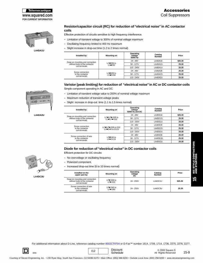
Resistor/capacitor ci rcuit (RC) for reduction o f “electrical noise ” in AC contactor coilsEffective protection of circuits sensitive to high frequency interference.
– Limitation of transient voltage to 300% of nominal voltage maximum
– Oscillating frequency limited to 400 Hz maximum
– Slight increase in drop-out time (1.2 to 2 times normal)
Varistor (peak limiting) for reduction o f “electrical noise ” in AC or DC contactor coilsSimple component operating in AC and DC
– Limitation of transient voltage value to 200% of nominal voltage maximum
– Maximum reduction of transient voltage peaks
– Slight increase in drop-out time (1.1 to 1.5 times normal)
Diode for reduction o f “electrical noise ” in DC contactor coilsEfficient protection for DC circuits:
– No overvoltage or oscillating frequency
– Polarized component.
– Increased drop-out time (6 to 10 times normal)
Installed by: Mountin g onOperating
voltage50/60 Hz
Catalog Number Price
Snap-on mounting and connectionwithout tools to the contactor
coil terminals
LCkD09 toLCkD32
24 - 48V LA4DA1E $25.30
50 - 127V LA4DA1G 25.30
110 - 240V LA4DA1U 25.30
Screw connectionto the contactorcoil terminals
LCkD09 toLCkD150
24 - 48V LA4DA2E 25.30
50 - 127V LA4DA2G 25.30
110 - 240V LA4DA2U 25.30
Installed by: Mounting onOperating
voltage50/60 Hz and DC
Catalog Number Price
Snap-on mounting and connectionwithout tools to the contactor
coil terminals
LCk/LPk D09 toLCk/LPk D32
24 - 48V LA4DE1E $25.30
50 - 127V LA4DE1G 25.30
110 - 250V LA4DE1U 25.30
Screw connectionto the contactorcoil terminals
LCk/LPk D09 to D32LCk/D40 to D115
24 - 48V LA4DE2E 25.30
50 - 127V LA4DE2G 25.30
110 - 250V LA4DE2U 25.30
Screw connection of wireto the contactorcoil terminals
LPkD40 to LPk D115
24 - 48V LA4DE3E 25.30
50 - 127V LA4DE3G 25.30
110 - 250V LA4DE3U 25.30
Installed on the upper pa rt by: Mounting on
Operatingvoltage
DC
Catalog Number
Price
Snap-on mounting and connectionwithout tools to the contactor
coil terminals
LPk D09 toLPk D32 24 - 250V LA4DC1U $25.30
Screw connection of wireto the contactorcoil terminals
LPk D40 toLPk D80 24 - 250V LA4DC3U 25.30
LA4DA1U
LA4DA2U
LA4DC3U
AccessoriesCoil Suppressors
For additional information about D-Line, reference catalog number 8502CT9704 or D-Fax™ number 1614, 1709, 1714, 1736, 2275, 2276, 2277.
Courtesy of Steven Engineering, Inc. ! 230 Ryan Way, South San Francisco, CA 94080-6370 ! Main Office: (650) 588-9200 ! Outside Local Area: (800) 258-9200 ! www.stevenengineering.com
15-10
15IE
C S
TY
LE
CO
NT
AC
TO
RS
AN
D S
TA
RT
ER
S
I12 DiscountSchedule 3/00
© 2000 Square DAll Rights Reserved
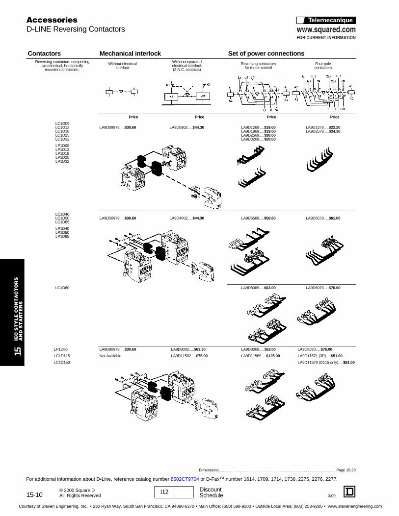
Contacto rs Mechanical interlo ck Set of p ower connectionsReversing contactors comprising
two identical, horizontallymounted contactors :
Without electricalinterlock
With incorporatedelectrical interlock(2 N.C. contacts)
Reversing contactors for motor control
Four polecontactors
Pric e Price Price Price
LC1D09LC1D12LC1D18LC1D25LC1D32
LA9D09978.....$30.60 LA9D0902.....$44.30 LA9D1269.....$19.00LA9D1869.....$19.00LA9D2569.....$20.00LA9D3269.....$20.00
LA9D1270.....$22.20LA9D2570.....$24.30
LP1D09LP1D12LP1D18LP1D25LP1D32
LC1D40LC1D50LC1D65
LA9D50978.....$30.60 LA9D4002.....$44.30 LA9D6569.....$50.60 LA9D6570.....$61.00
LP1D40LP1D50LP1D65
LC1D80 LA9D8069.....$63.00 LA9D8070.....$76.00
LP1D80 LA9D80978.....$30.60 LA9D8002.....$63.30 LA9D8069.....$63.00 LA9D8070.....$76.00
LC1D115 Not Available LA9D11502.....$75.00 LA9D11569.....$125.00 LA9D11571 (3P).....$51.00
LC1D150 LA9D11570 (D115 only).....$51.00
AccessoriesD-LINE Reversing Contactors
Dimensions. . . . . . . . . . . . . . . . . . . . . . . . . . . . . . . . . . . . . . . . . . . . . . . . . . . . . . . . . . Page 15-29
For additional information about D-Line, reference catalog number 8502CT9704 or D-Fax™ number 1614, 1709, 1714, 1736, 2275, 2276, 2277.
Courtesy of Steven Engineering, Inc. ! 230 Ryan Way, South San Francisco, CA 94080-6370 ! Main Office: (650) 588-9200 ! Outside Local Area: (800) 258-9200 ! www.stevenengineering.com
15-11I12 DiscountSchedule3/00
15IE
C S
TY
LE
CO
NT
AC
TO
RS
AN
D S
TA
RT
ER
S
© 2000 Square DAll Rights Reserved
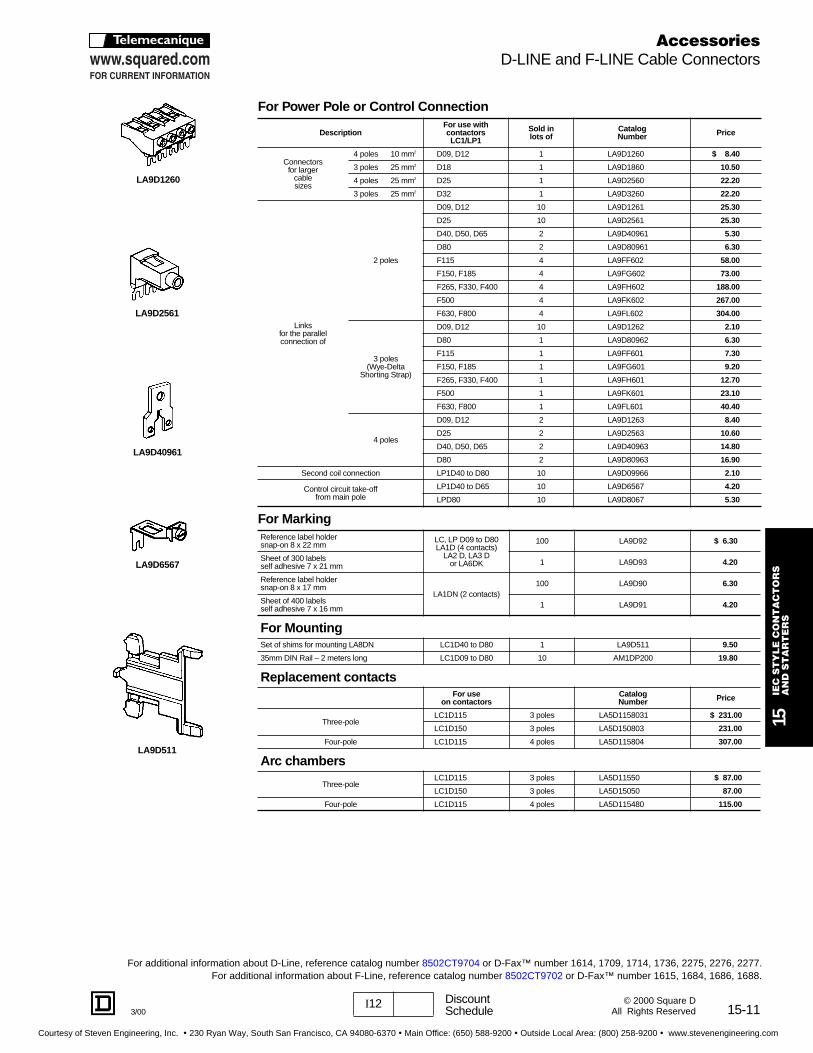
For Power Pole or Cont rol Connection
DescriptionFor use withcontacto rsLC1/LP1
Sold in lots of
CatalogNumber Price
Connectorsfor larger
cablesizes
4 poles 10 mm2 D09, D12 1 LA9D1260 $ 8.40
3 poles 25 mm2 D18 1 LA9D1860 10.50
4 poles 25 mm2 D25 1 LA9D2560 22.20
3 poles 25 mm2 D32 1 LA9D3260 22.20
Linksfor the parallel connection of
2 poles
D09, D12 10 LA9D1261 25.30
D25 10 LA9D2561 25.30
D40, D50, D65 2 LA9D40961 5.30
D80 2 LA9D80961 6.30
F115 4 LA9FF602 58.00
F150, F185 4 LA9FG602 73.00
F265, F330, F400 4 LA9FH602 188.00
F500 4 LA9FK602 267.00
F630, F800 4 LA9FL602 304.00
3 poles(Wye-Delta
Shorting Strap)
D09, D12 10 LA9D1262 2.10
D80 1 LA9D80962 6.30
F115 1 LA9FF601 7.30
F150, F185 1 LA9FG601 9.20
F265, F330, F400 1 LA9FH601 12.70
F500 1 LA9FK601 23.10
F630, F800 1 LA9FL601 40.40
4 poles
D09, D12 2 LA9D1263 8.40
D25 2 LA9D2563 10.60
D40, D50, D65 2 LA9D40963 14.80
D80 2 LA9D80963 16.90
Second coil connection LP1D40 to D80 10 LA9D09966 2.10
Control circuit take-offfrom main pole
LP1D40 to D65 10 LA9D6567 4.20
LPD80 10 LA9D8067 5.30
For MarkingReference label holdersnap-on 8 x 22 mm
LC, LP D09 to D80LA1D (4 contacts)
LA2 D, LA3 Dor LA6DK
100 LA9D92 $ 6.30
Sheet of 300 labelsself adhesive 7 x 21 mm 1 LA9D93 4.20
Reference label holdersnap-on 8 x 17 mm
LA1DN (2 contacts)100 LA9D90 6.30
Sheet of 400 labelsself adhesive 7 x 16 mm 1 LA9D91 4.20
For MountingSet of shims for mounting LA8DN LC1D40 to D80 1 LA9D511 9.50
35mm DIN Rail – 2 meters long LC1D09 to D80 10 AM1DP200 19.80
Replacement contacts For use
on contacto rsCatalogNumber Price
Three-poleLC1D115 3 poles LA5D1158031 $ 231.00
LC1D150 3 poles LA5D150803 231.00
Four-pole LC1D115 4 poles LA5D115804 307.00
Arc chambe rs
Three-poleLC1D115 3 poles LA5D11550 $ 87.00
LC1D150 3 poles LA5D15050 87.00
Four-pole LC1D115 4 poles LA5D115480 115.00
LA9D1260
LA9D2561
LA9D40961
LA9D6567
LA9D511
AccessoriesD-LINE and F-LINE Cable Connectors
For additional information about D-Line, reference catalog number 8502CT9704 or D-Fax™ number 1614, 1709, 1714, 1736, 2275, 2276, 2277.For additional information about F-Line, reference catalog number 8502CT9702 or D-Fax™ number 1615, 1684, 1686, 1688.
Courtesy of Steven Engineering, Inc. ! 230 Ryan Way, South San Francisco, CA 94080-6370 ! Main Office: (650) 588-9200 ! Outside Local Area: (800) 258-9200 ! www.stevenengineering.com
15-12
15IE
C S
TY
LE
CO
NT
AC
TO
RS
AN
D S
TA
RT
ER
S
I12 DiscountSchedule 3/00
© 2000 Square DAll Rights Reserved
F-line contactors accept most of the D-line front mount auxiliary blocks. This limits the number of different auxiliarycontacts, etc. required when working with a range of contactor sizes.
t Including 1 N.O. + 1 N.C. make-before-break.
q Device supplied with 4 grounding terminal points.
c With extended range from 0.1 to 0.6 s.a With switching time of 40 ms ± 15 ms between the opening of the N.C. contact and the closing of the N.O. contact.
Standa rd, instantaneous auxiliary contact blo cks
For use withNumber
ofcontacts
Maximum numberof blo cks
per contactor
Composition CatalogNumber Price
N.O. N.C.
LC1F
Left-sidemounting 1 1
1 - LA1DN10 $12.70
- 1 LA1DN01 12.70
Right-sidemounting
2 2
1 1 LA1DN11 20.00
2 - LA1DN20 20.00
- 2 LA1DN02 20.00
4 2
2 2 LA1DN22 40.10
1 3 LA1DN13 40.10
4 - LA1DN40 40.10
- 4 LA1DN04 40.10
3 1 LA1DN31 40.10
2 2 LA1DC22 t 40.10
Instantaneous auxiliary contact blo cks with dust tight contacts (IP54) NEM A Type 12Recommended for particularly severe industrial ambient atmospheres.
For use withNumber
ofcontacts
Maximum numberof blo cks
per contactor
CompositionCatalogNumber Pric eDusttight Standa rd
N.O. N.C. N.O. N.C.
LC1F
2 22 - - - LA1DX20 $63.00
2 - - - LA1DY20 q 74.00
4 22 - 2 - LA1DZ40 79.00
2 - 1 1 LA1DZ31 79.00
Pneumatic time del ay auxiliary contact blo cks
For use withNumber
of contacts
Maximum numberof blo cks per
contactor
Time del ay CatalogNumber Price
Type Range
LC1F1 N.O.
+1 N.C.
2
On-delay
0.1 to 3 s c LA2DT0 $127.00
0.1 to 30 s LA2DT2 127.00
10 to 180 s LA2DT4 127.00
1 to 30 s a LA2DS2 127.00
Off-delay
0.1 to 3 s c LA3DR0 127.00
0.1 to 30 s LA3DR2 127.00
10 to 180 s LA3DR4 127.00
Protective sh roudsThese clear plastic protective shrouds are an effective way to meet international finger-safe requirements forpower terminals. They are designed to be used with power cables that have been bolted to the terminal. Theydo not attach to contactors utilizing DZ2 F lug kits.
For use withPackage Catalog
Number PriceLC1F Contactor LR9F Overload Rel ay
F115, F150, F185two and three pole
F5k57 Set of 6 single pole shrouds LA9F701 $ 47.00
F5k63 - F5k69 Set of 6 single pole shrouds LA9F702 65.00
F225 - F500two and three pole F7k75 - F9k31 Set of 6 single pole shrouds LA9F703 91.00
F630, 800two and three pole F7k81 Set of 6 single pole shrouds LA9F704 98.00
F1154 – Set of 8 single pole shrouds LA9F706 61.00
F1504 and F1854 – Set of 8 single pole shrouds LA9F707 84.00
F2564 - F5004 – Set of 8 single pole shrouds LA9F708 117.00
F6304 – Set of 8 single pole shrouds LA9F709 127.00
LA1DN11
LA1DN22
LA1DX, DY, DZ
LA2DT, DS
LA3DR
LA9F70k
Dimensions . . . . . . . . . . . . . . . . . . . . . . . . . . . . . . . . . . . . . . . . . . . . . . . . . . .Pages 15-31–15-32
AccessoriesAuxilliary Contacts, Time Delay, Contact Blocks
For additional information about F-Line, reference catalog number 8502CT9702 or D-Fax™ number 1615, 1684, 1686, 1688.
Courtesy of Steven Engineering, Inc. ! 230 Ryan Way, South San Francisco, CA 94080-6370 ! Main Office: (650) 588-9200 ! Outside Local Area: (800) 258-9200 ! www.stevenengineering.com
15-13I12 DiscountSchedule3/00
15IE
C S
TY
LE
CO
NT
AC
TO
RS
AN
D S
TA
RT
ER
S
© 2000 Square DAll Rights Reserved
a Supplied per pole are: 2 fixed contacts, 1 moving contact, 2 deflectors, 1 backplate, mounting screws and washers.c Comprises single-pole components.f Comprises 2-pole components.q 2 identical components per pole are supplied.
For useon contacto rs
CatalogNumber Price
Replacement contacts sets a
Two-pole
LC1F4002 2 poles LA5F400802 $ 693.00
LC1F5002 2 poles LA5F500802 1073.00
LC1F6302 2 poles LA5F630802 1595.00
Three-pole
LC1F115, F150 3 poles LA5FF431 231.00
LC1F185 3 poles LA5FG431 404.00
LC1F265 3 poles LA5FH431 766.00
LC1F330, F400 3 poles LA5F400803 1040.00
LC1F500 3 poles LA5F500803 1535.00
LC1F630 3 poles LA5F630803 2404.00
LC1F780 1 pole LA5F780801q 1595.00
LC1F800 3 poles LA5F800803 2404.00
Four-pole
LC1F1504, F1154 4 poles LA5FF441 307.00
LC1F1854 4 poles LA5FG441 538.00
LC1F2654 4 poles LA5FH441 1021.00
LC1F3304, F400, F4004 4 poles LA5F400804 1386.00
LC1F5004 4 poles LA5F500804 2378.00
LC1F6304 4 poles LA5F630804 3192.00
LC1F7804 1 pole LA5F780801q 1595.00
Arc chambe rs
Two-pole
LC1F4002 2 poles LA5F400250 $277.00
LC1F5002 2 poles LA5F500250 295.00
LC1F6302 2 poles LA5F630250 416.00
Three-pole
LC1F115 3 poles LA5F11550 87.00
LC1F150 3 poles LA5F15050 98.00
LC1F185 3 poles LA5F18550 173.00
LC1F265 3 poles LA5F26550 260.00
LC1F330 3 poles LA5F33050 277.00
LC1F400 3 poles LA5F40050 295.00
LC1F500 3 poles LA5F50050 329.00
LC1F630 3 poles LA5F63050 624.00
LC1F780 1 pole LA5F80150q 416.00
LC1F800 3 poles LA5F80050 624.00
Four-pole
LC1F1154 4 poles LA5F115450 115.00
LC1F1504 4 poles LA5F150450 127.00
LC1F1854 4 poles LA5F185450 202.00
LC1F2654 4 poles LA5F265450 289.00
LC1F3304 4 poles LA5F330450 491.00
LC1F4004 4 poles LA5F400450f 554.00
LC1F5004 4 poles LA5F500450f 589.00
LC1F6304 4 poles LA5F630450c 832.00
LC1F7804 1 pole LA5F780150q 416.00
LA5FG431
LA5F11550
Replacement PartsF-LINE Contact Kits, Arc Chambers
For additional information about F-Line, reference catalog number 8502CT9702 or D-Fax™ number 1615, 1684, 1686, 1688.
Courtesy of Steven Engineering, Inc. ! 230 Ryan Way, South San Francisco, CA 94080-6370 ! Main Office: (650) 588-9200 ! Outside Local Area: (800) 258-9200 ! www.stevenengineering.com

15-14 I12 DiscountSchedule
15IE
C S
TY
LE
CO
NT
AC
TO
RS
A
ND
ST
AR
TE
RS
3/00© 2000 Square DAll Rights Reserved
t With identical or different numbers of poles.q Double mechanical interlock with 2 mechanical links and 3 power connection bars.c Double mechanical interlock with 2 mechanical links and 4 power connection bars.f Power connection to be assembled by the customer, except for contactors LC1 F780 and F7804.
Component pa rts for the assemb ly of F-Line 3-pole r eversing contacto rsWith
2 identicalcontacto rs t
Set of p ower connectionsCatalog number Price Mechanical interlo ck kit
catalog number Price
Horizontal mounting
LC1F115 LA9FF976 $ 102.00 LA9FF970 $ 50.80
LC1F150 LA9F15076 102.00 LA9FF970 50.80
LC1F185 LA9FG976 109.00 LA9FG970 50.80
LC1F265 LA9FH976 159.00 LA9FJ970 73.00
LC1F330 LA9FJ976 217.00 LA9FJ970 73.00
LC1F400 LA9FJ976 217.00 LA9FJ970 73.00
LC1F500 LA9FK976 296.00 LA9FJ970 73.00
LC1F630 or F800 LA9FL976 549.00 LA9FL970 73.00
Vertical mounting
LC1 F115 or F150 f – LA9FF4F $109.00
LC1F185 f – LA9FG4G 109.00
LC1F265 f – LA9FH4H 144.00
LC1F330 f – LA9FJ4J 144.00
LC1F400 f – LA9FJ4J 144.00
LC1F500 f – LA9FK4K 144.00
LC1F630 or F800 f – LA9FL4L 144.00
LC1F780 q – LA9FX970 q 491.00
Component pa rts for the assemb ly of F-line 3-pole or 4-pole transfer contacto rsHorizontal mounting three-pole four-pole Price Price
LC1F115/4 LA9FF982 LA9FF977 $ 51.00 LA9FF970 $ 50.80
LC1F150/4 LA9F15082 LA9F15077 51.00 LA9FF970 50.80
LC1F185/4 LA9FG982 LA9FG977 51.00 LA9FG970 50.80
LC1F265/4 LA9FH982 LA9FH977 80.00 LA9FJ970 73.00
LC1F330/4 LA9FJ982 LA9FJ977 109.00 LA9FJ970 73.00
LC1F400/4 LA9FJ982 LA9FJ977 109.00 LA9FJ970 73.00
LC1F500/4 LA9FK982 LA9FK977 149.00 LA9FJ970 73.00
LC1F630/4 LA9FL982 LA9FL977 275.00 LA9FL970 73.00
Vertical mounting
LC1F115/4 f – – LA9FF4F $109.00
LC1F185/4 f – – LA9FG4G 109.00
LC1F265/4 f – – LA9FH4H 144.00
LC1F330/4 f – – LA9FJ4J 144.00
LC1F400/4 f – – LA9FJ4J 144.00
LC1F500/4 f – – LA9FK4K 144.00
LC1F630/4 f – – LA9FL4L 144.00
LC1F780/4 c – – LA9FX970 c 491.00
Vertical mounting of 2 contacto rs of different ratings t
Upper Contactor Lower Contactor Mechanical interlo ckkit catalog number Price
LC1F185 or 1854 LC1F115/150 or 1154/1504 LA9FG4F $109.00
LC1F265 or 2654 LC1F115/150 or 1154/1504 LA9FH4F 122.00
LC1F330 or 3304 LC1F185/1854 or 265/265A LA91FH4G 122.00
LC1F400 or 4004
LC1F115/150 or 1154/1504 LA91FJ4F 122.00
LC1F185 or 1854 LA91FJ4G 122.00
LC1F265/2654 or 330/330A LA91FJ4H 144.00
LC1F500 or 5004
LC1F115/150 or 1154/1504 LA91FK4F 122.00
LC1F185 or 1854 LA91FK4G 122.00
LC1F265/2654 or 330/330A LA91FK4H 144.00
LC1F400 or 4004 LA9FK4J 144.00
LC1F630, 6304 orLC1F800
LC1F115/150 or 1154/1504 LA9FL4F 122.00
LC1F185 or 1854 LA9FL4G 122.00
LC1F265/2654 or 330/330A LA9FL4H 144.00
LC1F400 or 4004 LA9FL4J 144.00
LC1F500 or 5004 LA9FL4K 144.00
AccessoriesF-LINE Reversing Contactors
For additional information about F-Line, reference catalog number 8502CT9702 or D-Fax™ number 1615, 1684, 1686, 1688.
Courtesy of Steven Engineering, Inc. ! 230 Ryan Way, South San Francisco, CA 94080-6370 ! Main Office: (650) 588-9200 ! Outside Local Area: (800) 258-9200 ! www.stevenengineering.com

15-153/00I12 Discount
Schedule
15IE
C S
TY
LE
CO
NT
AC
TO
RS
AN
D S
TA
RT
ER
S
© 2000 Square DAll Rights Reserved
Note: Lower contactor must have equal or lower current rating.
Horizontal mounting Mechanical interlo cks Set of p ower connectionsReversers assembled
contactorswith two contactorsof identical ratings: LA9F•970
Reversing contactors
three poleLA9F•976
Changeover
three pole four poleLA9F•982 LA9F•977
LC1F115 or F1154LC1F150 or F1504LC1F185 or F1854LC1F265 or F2654LC1F330 or F3304LC1F400 or F4004LC1F500 or F5004LC1F630 or F6304LC1F800
LA9 F•982
Vertical mounting Mechanical interlo cksReversers assembledwith two contactorsof identical ratings:
LC1F115 or F1154LC1F150 or F1504LC1F185 or F1854LC1F265 or F2654LC1F330 or F3304LC1F400 or F4004LC1F500 or F5004LC1F630 or F6304LC1F800
LA9FF4FLA9FG4G
LA9FH4HLA9FJ4JLA9FK4KLA9FL4L
LC1F780LC1F7804 LA9FX970 (three pole reverser) LA9FX971 (four pole transfer)
Reversers assembledwith two contactorsof different ratings:LC1F115 or F1154LC1F150 or F1504LC1F185 or F1854LC1F265 or F2654LC1F330 or F3304LC1F400 or F4004LC1F500 or F5004LC1F630 or F6304
LA9FH4HLA9FJ4FLA9FK4FLA9FL4FLA9FH4GLA9FJ4GLA9FL4GLA9FL4G
LA9FJ4HLA9FK4HLA9FL4HLA9FK4JLA9FL4JLA9FL4K
L1 L2 L3
A1
A2
A1
A2
1 3 5 1 3 5
2 4 6 2 4 6
U V W
A1
A2
A1
A2
1N 1L2 2L1 2L3
1L3 1L1 2L2 2N
1 3 5 7 1 3 5 7
2 4 6 8 2 4 6 8
L1 L2 L3 N
AccessoriesF-LINE Reversing Contactors
For additional information about F-Line, reference catalog number 8502CT9702 or D-Fax™ number 1615, 1684, 1686, 1688.
Courtesy of Steven Engineering, Inc. ! 230 Ryan Way, South San Francisco, CA 94080-6370 ! Main Office: (650) 588-9200 ! Outside Local Area: (800) 258-9200 ! www.stevenengineering.com

15-16
15IE
C S
TY
LE
CO
NT
AC
TO
RS
AN
D S
TA
RT
ER
S
I12 DiscountSchedule
3/00© 2000 Square DAll Rights Reserved
f For use in 24 volt applications involving serial timer modules. Refer to page 15-8.
For LC1 D09 , D12, D18 Contacto rsRated voltage
nominal voltageV
Catalog Number50 Hz
Catalog Number60 Hz
Catalog Number 50/60 Hz Price
21 f LX1D2Z5 LX1D2Z6 LX1D2Z7 $25.3024 LX1D2B5 LX1D2B6 LX1D2B7 25.3032 LX1D2C5 – – 25.3042 LX1D2D5 – LX1D2D7 25.3048 LX1D2E5 LX1D2E6 LX1D2E7 25.30110 LX1D2F5 LX1D2F6 LX1D2F7 25.30120 – LX1D2G6 LX1D2G7 25.30127 LX1D2G5 – – 25.30208 – LX1D2L6 – 25.30220 LX1D2M5 LX1D2M6 LX1D2M7 25.30230 LX1D2P5 – LX1D2P7 25.30240 LX1D2U5 LX1D2U6 LX1D2U7 25.30256 LX1D2W5 – – 25.30277 – LX1D2W6 – 25.30380 LX1D2Q5 LX1D2Q6 LX1D2Q7 25.30400 LX1D2V5 – LX1D2V7 25.30415 LX1D2N5 – LX1D2N7 25.30440 LX1D2R5 LX1D2R6 LX1D2R7 25.30480 – LX1D2T6 – 25.30500 LX1D2S5 – – 25.30575 – LX1D2S6 – 25.30600 – LX1D2X6 – 25.30660 LX1D2Y5 – – 25.30
Specification 50 Hz 60 Hz 50/60 HzAverage consumption
• inrush (inductance .75) 60 VA 70 VA 70 VA at 50 or 60 Hz• sealed (inductance .3) 7 VA 7.5 VA 8 VA at 50 or 60 Hz
Operating range at q ≤ 55°C / 131°F
80-110 % ofnominal voltage
80-110% of nominal voltage
85-110% ofnominal voltage
For LC1 D25 , D32Rated voltage
nominal voltage (V)Catalog Number
50 HzCatalog Number
60 HzCatalog Number
50/60 Hz Price
21 f LX1D4Z5 LX1D4Z6 LX1D4Z7 $34.8024 LX1D4B5 LX1D4B6 LX1D4B7 34.8032 LX1D4C5 – – 34.8042 LX1D4D5 – LX1D4 D7 34.8048 LX1D4E5 LX1D4E6 LX1D4E7 34.80110 LX1D4F5 LX1D4F6 LX1D4F7 34.80120 – LX1D4G6 LX1D4G7 34.80127 LX1D4G5 – – 34.80208 – LX1D4L6 – 34.80220 LX1D4M5 LX1D4M6 LX1D4M7 34.80230 LX1D4P5 – LX1D4P7 34.80240 LX1D4U5 LX1D4U6 LX1D4U7 34.80256 LX1D4W5 – – 34.80277 – LX1D4W6 – 34.80380 LX1D4Q5 LX1D4Q6 LX1D4Q7 34.80400 LX1D4V5 – LX1D4V7 34.80415 LX1D4N5 – LX1D4N7 34.80440 LX1D4R5 LX1D4R6 LX1D4R7 34.80480 – LX1D4T6 – 34.80500 LX1D4S5 – – 34.80575 – LX1D4S6 – 34.80600 – LX1D4X6 – 34.80660 LX1D4Y5 – – 34.80
Specification 50 Hz 60 Hz 50/60 HzAverage consumption
• inrush (inductance .75) 90 VA 100 VA 100 VA at 50 or 60 Hz• sealed (inductance .3) 7.5 VA 8.5 VA 8.5 VA at 50 or 60 Hz
Operating range 80-110% of 80-110% of 85-110% ofat q ≤ 55°C / 131°F nominal voltage nominal voltage nominal voltage
LX1D2
Repair PartsD-LINE AC Coils
For additional information about D-Line, reference catalog number 8502CT9704 or D-Fax™ number 1614, 1709, 1714, 1736, 2275, 2276,2277.
Courtesy of Steven Engineering, Inc. ! 230 Ryan Way, South San Francisco, CA 94080-6370 ! Main Office: (650) 588-9200 ! Outside Local Area: (800) 258-9200 ! www.stevenengineering.com
15-17I12 DiscountSchedule3/00
15IE
C S
TY
LE
CO
NT
AC
TO
RS
AN
D S
TA
RT
ER
S
© 2000 Square DAll Rights Reserved
For LC1 D40 , D50, D65, D80 For LC1 D115 , D150Rated voltage
nominal voltageV
Catalog Number50 Hz
Catalog Number60 Hz
Catalog Number 50/60 Hz Price
Rated voltage nominal voltage
V
Catalog Number50 Hz
Catalog Number60 Hz
Catalog Number 50/60 Hz Price
24 LX1D6B5 LX1D6B6 LX1D6B7 $40.10 24 LX1D8B5 LX1D8B6 LX1D8B7 $75.0032 LX1D6C5 – – 40.10 32 LX1D8C5 — LX1D8C7 75.0042 LX1D6D5 – LX1D6D7 40.10 42 LX1D8D5 — LX1D8D7 75.0048 LX1D6E5 LX1D6E6 LX1D6E7 40.10 48 LX1D8E5 LX1D8E6 LX1D8E7 75.00
110 LX1D6F5 LX1D6F6 LX1D6F7 40.10 110 LX1D8F5 LX1D8F6 LX1D8F7 75.00120 – LX1D6G6 LX1D6G7 40.10 115 LX1D8FE5 — LX1D8FE7 75.00127 LX1D6G5 – – 40.10 120 — LX1D8G6 LX1D8G7 75.00208 – LX1D6L6 – 40.10 127 LX1D8FC5 — LX1D8FC7 75.00 220 LX1D6M5 LX1D6M6 LX1D6M7 40.10 208 — LX1D8LG LX1D8L7 75.00230 LX1D6P5 – LX1D6P7 40.10 220/230 LX1D8M5 LX1D8M6 LX1D8M7 75.00240 LX1D6U5 LX1D6U6 LX1D6U7 40.10 230 LX1D8P5 — LX1D8P7 75.00256 LX1D6W5 – – 40.10 240 LX1D8U5 LX1D8U6 LX1D8U7 75.00277 – LX1D6W6 – 40.10 277 — LX1D8W6 LX1D8W7 75.00380 LX1D6Q5 LX1D6Q6 LX1D6Q7 40.10 380/400 LX1D8Q5 LX1D8Q6 LX1D8Q7 75.00400 LX1D6V5 – LX1D6V7 40.10 400 LX1D8V5 — LX1D8V7 75.00415 LX1D6N5 – LX1D6N7 40.10 415 LX1D8N5 — LX1D8N7 75.00440 LX1D6R5 LX1D6R6 LX1D6R7 40.10 440 LX1D8R5 LX1D8R6 LX1D8R7 75.00480 – LX1D6T6 – 40.10 480 — LX1D8T6 LX1D8T7 75.00500 LX1D6S5 – – 40.10 500 LX1D8S5 — LX1D8S6 75.00575 – LX1D6S6 – 40.10600 – LX1D6X6 – 40.10660 LX1D6Y5 – – 40.10
Specification 50 Hz 60 Hz 50/60 Hz Specification 50 Hz 60 Hz 50/60 HzAverage consumption
- inrush (inductance .75)- sealed (inductance .3)
200 VA20 VA
220 VA 22 VA
245 VA at 50 or 60 Hz 26 VA at 50 or 60 Hz
Average consumption- inrush (inductance .3)- sealed (inductance .3)
300 VA22 VA
300 VA 22 VA
350 Va 18Va
- inrush (.9)- sealed (.9)
Operating range at q ≤ 55°C / 131°F
80-110% ofnominal voltage
80-110% ofnominal voltage
85-110% ofnominal voltage
Operating range A7 q ≤ 55°C / 131°F
85-110% ofnominal voltage
85-110% ofnominal voltage
80-115% ofnominal voltage
For LC1 F115 , F150, F185, F265, F330, F400, F500, F630, F780, F800LX1 coils are the standard coils that are included when a voltage code is added to the contactor part number. The LX9 coils may be ordered separatelyfor special applications. LX9 coils do not include a built-in normally open holding circuit contact; a separate auxiliary contact block with a N.O. contactshould be added to the contactor. Both the LX1 and LX9 coils can be used on the previous F-line contactors.
t LClF780 contactors operate on 2 coils as a set. The LX1FX part number includes both coils.
DeviceType Hz Catalog
NumberkCatalog Number Suffix
24V 48V 110V 120V 208V 220V 240V 277V 380V 415V 440V 480V 600V Price
F115 - F15050 LX1FFk 024 048 110 127 200 220 240 264 380 415 415 500 600 $ 75.0060 LX1FFk 020 040 092 095 162 184 187 220 316 340 360 380 475 75.00
40-400 LX9FFk - 048 110 127 200 220 220 260 380 415 415 500 - 75.00
F18550 LX1FGk 024 048 110 127 200 220 240 264 380 415 415 450 600 104.0060 LX1FGk 020 040 092 095 162 184 187 220 316 340 360 380 475 104.00
40-400 LX9FGk - 048 110 127 200 220 220 260 380 415 415 500 - 104.00
F265 - F33040-400 LX1FHk 0242 0482 1102 1272 2002 2202 2402 2772 3802 3802 4402 5002 6002 133.0040-400 LX9FHk - 0482 1102 1272 2002 2202 2402 2772 3802 3802 - 5002 - 133.00
F40040-400 LX1FJk - 048 110 110 200 220 240 280 380 415 415 415 600 271.0040-400 LX9FJk f 910 917 925 925 930 931 932 932 936 936 937 937 - 271.00
F50040-400 LX1FKk - 048 110 110 200 220 240 280 380 415 415 415 600 381.0040-400 LX9FKk f 910 917 925 925 930 931 932 932 936 936 937 937 - 381.00
F63040-400 LX1FLk - 048 110 110 200 220 240 260 380 415 415 415 600 535.0040-400 LX9FLk f 910 917 924 925 930 930 931 932 935 936 936 937 - 535.00
F780, FX t 40-400 LX1FXk - - 110 110 200 220 220 280 380 415 415 415 - 1068.00F800 50/60 LX8F8 — — FW FW — MW MW — QW QW QW — — 700.00
LX1D6
Application Note on Contactor D rop-ou t Times:
Contactors using LX1, FH, FJ, FK, FL, and FX coils have longer drop-out times.For critical applications such as emergency stop functions:– Select a fast drop-out coil (LX9), or– Use a maintained contact Stop button, or– Use an interposing relay.
Repair PartsD- and F-LINE AC Coils
For additional information about D-Line, reference catalog number 8502CT9704 or D-Fax™ number 1614, 1709, 1714, 1736, 2275, 2276,2277.For additional information about F-Line, reference catalog number 8502CT9702 or D-Fax™ number 1615, 1684, 1686, 1688.
f Coil Ci rcuit requires a separate ly mounted rectifie r. Order f rom table bel ow.Coil Rectifier Catalog Number Price
LX9Fk910 DR5TF4V $79.00LX9Fk917 DR5TF4V 79.00LX9Fk925 DR5TE4U 79.00LX9Fk926 DR5TE4U 79.00LX9Fk931 DR5TE4U 79.00LX9Fk936 DR5TE4S 79.00LX9Fk937 DR5TE4S 79.00LX9Fk938 DR5TE4S 79.00
Courtesy of Steven Engineering, Inc. ! 230 Ryan Way, South San Francisco, CA 94080-6370 ! Main Office: (650) 588-9200 ! Outside Local Area: (800) 258-9200 ! www.stevenengineering.com
15-18
15IE
C S
TY
LE
CO
NT
AC
TO
RS
AN
D S
TA
RT
ER
S
I12 DiscountSchedule 3/00
© 2000 Square DAll Rights Reserved
f For use in 24 volt applications involving serial timer modules. Refer to page 15-8.
For LP1 D09 , D12, D18 Contacto rsRated voltage
nominal voltageV
Catalog Number Catalog NumberWide range Price
12 LX4D2JD LX4D2JW $38.00
21 f LX4D2ZD – 38.00
24 LX4D2BD LX4D2BW 38.00
36 LX4D2CD LX4D2CW 38.00
48 LX4D2ED LX4D2EW 38.00
60 LX4D2ND – 38.00
72 LX4D2SD LX4D2SW 38.00
110 LX4D2FD LX4D2FW 38.00
125 LX4D2GD – 38.00
220 LX4D2MD LX4D2MW 38.00
250 LX4D2UD – 38.00
440 LX4D2RD – 38.00
600 LX4D2XD – 38.00
SpecificationsAverage consumption 9 W 11 W
Operating range at q – 55°C / 131°F
80-110% ofnominal voltage
70-125% ofnominal voltage
For LP1 D25 , D32Rated voltage
nominal voltageV
Catalog Number Catalog NumberWide range Price
12 LX4D4JD LX4D4JW $53.00
21 f LX4D4ZD – 53.00
24 LX4D4BD LX4D4BW 53.00
36 LX4D4CD LX4D4CW 53.00
48 LX4D4ED LX4D4EW 53.00
60 LX4D4ND – 53.00
72 LX4D4SD LX4D4SW 53.00
110 LX4D4FD LX4D4FW 53.00
125 LX4D4GD – 53.00
220 LX4D4MD LX4D4MW 53.00
250 LX4D4UD – 53.00
440 LX4D4RD – 53.00
600 LX4D4XD – 53.00
SpecificationsAverage consumption 11 W 13 W
Operating rangeat q ≤ 55°C / 131°F
80-110% ofnominal voltage
70-125% ofnominal voltage
LX4D2
Repair PartsD-LINE DC Coils
For additional information about D-Line, reference catalog number 8502CT9704 or D-Fax™ number 1614, 1709, 1714, 1736, 2275, 2276,2277.
Courtesy of Steven Engineering, Inc. ! 230 Ryan Way, South San Francisco, CA 94080-6370 ! Main Office: (650) 588-9200 ! Outside Local Area: (800) 258-9200 ! www.stevenengineering.com
15-19I12 DiscountSchedule3/00
15IE
C S
TY
LE
CO
NT
AC
TO
RS
AN
D S
TA
RT
ER
S
© 2000 Square DAll Rights Reserved
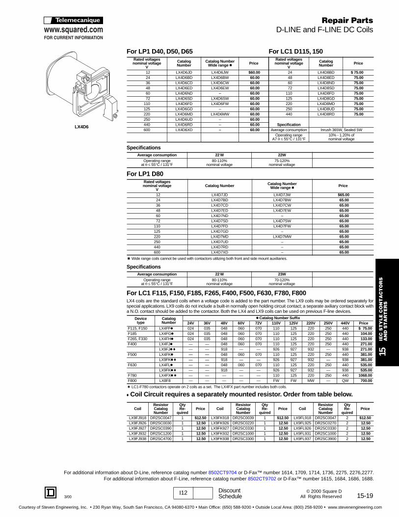
c Wide range coils cannot be used with contactors utilizing both front and side mount auxiliaries.
t LC1-F780 contactors operate on 2 coils as a set. The LX4FX part number includes both coils.
f Coil Ci rcuit requires a separate ly mounted resisto r. Order f rom table bel ow.
For LP1 D40 , D50, D65 For LC1 D115 , 150Rated voltages nominal voltage
V
Catalog Number
Catalog NumberWide range c Price
Rated voltages nominal voltage
V
Catalog Number Price
12 LX4D6JD LX4D6JW $60.00 24 LX4D8BD $ 75.0024 LX4D6BD LX4D6BW 60.00 48 LX4D8ED 75.0036 LX4D6CD LX4D6CW 60.00 60 LX4D8ND 75.0048 LX4D6ED LX4D6EW 60.00 72 LX4D8SD 75.0060 LX4D6ND – 60.00 110 LX4D8FD 75.0072 LX4D6SD LX4D6SW 60.00 125 LX4D8GD 75.00
110 LX4D6FD LX4D6FW 60.00 220 LX4D8MD 75.00125 LX4D6GD – 60.00 250 LX4D8UD 75.00220 LX4D6MD LX4D6MW 60.00 440 LX4D8RD 75.00250 LX4D6UD – 60.00440 LX4D6RD – 60.00 Specification600 LX4D6XD – 60.00 Average consumption Inrush 365W, Sealed 5W
Operating range A7 q ≤ 55°C / 131°F
10% - 1.20% of nominal voltage
SpecificationsAverage consumption 22 W 22W
Operating range 80-110% 75-120%nominal voltageat q ≤ 55°C / 131°F nominal voltage
For LP1 D80Rated voltages nominal voltage
VCatalog Number Catalog Number
Wide range c Price
12 LX4D7JD LX4D7JW $65.0024 LX4D7BD LX4D7BW 65.0036 LX4D7CD LX4D7CW 65.0048 LX4D7ED LX4D7EW 65.0060 LX4D7ND – 65.0072 LX4D7SD LX4D7SW 65.00
110 LX4D7FD LX4D7FW 65.00125 LX4D7GD – 65.00220 LX4D7MD LX4D7MW 65.00250 LX4D7UD – 65.00440 LX4D7RD – 65.00600 LX4D7XD – 65.00
SpecificationsAverage consumption 22 W 23W
Operating range at q ≤ 55°C / 131°F
80-110%nominal voltage
70-120% nominal voltage
For LC1 F115 , F150, F185, F265, F400, F500, F630, F780, F800LX4 coils are the standard coils when a voltage code is added to the part number. The LX9 coils may be ordered separately forspecial applications. LX9 coils do not include a built-in normally open holding circuit contact; a separate axiliary contact block witha N.O. contact should be added to the contactor. Both the LX4 and LX9 coils can be used on previous F-line devices.
Devicetype
CatalogNumber
k Catalog Number Suffix24V 36V 48V 60V 72V 110V 125V 220V 250V 440V Price
F115, F150 LX4FFk 024 035 048 060 070 110 125 220 250 440 $ 75.00F185 LX4FGk 024 035 048 060 070 110 125 220 250 440 104.00F265, F330 LX4FHk 024 035 048 060 070 110 125 220 250 440 133.00F400 LX4FJk — — 048 060 070 110 125 220 250 440 271.00
LX9FJk f — — 918 — — 926 927 932 — 938 271.00F500 LX4FKk — — 048 060 070 110 125 220 250 440 381.00
LX9FKk f — — 918 — — 926 927 932 — 938 381.00F630 LX4FLk — — 048 060 070 110 125 220 250 440 535.00
LX9FKk f — — 918 — — 926 927 932 — 938 535.00F780 LX4FXk t — — — — — 110 125 220 250 440 1068.00F800 LX8F8 — — — — — FW FW MW — QW 700.00
CoilResistor Catalog Number
Qty Re-
quiredPrice Coil
Resistor Catalog Number
Qty Re-
quiredPrice Coil
Resistor Catalog Number
Qty Re-
quiredPrice
LX9FJ918 DR2SC0047 1 $12.50 LX9FK918 DR2SC0039 1 $12.50 LX9FL918 DR2SC0047 2 $12.50LX9FJ926 DR2SC0030 1 12.50 LX9FK926 DR2SC0220 1 12.50 LX9FL925 DR2SC0270 2 12.50LX9FJ927 DR2SC0390 1 12.50 LX9FK927 DR2SC0330 1 12.50 LX9FL926 DR2SC0330 2 12.50LX9FJ932 DR2SC1200 1 12.50 LX9FK932 DR2SC1000 1 12.50 LX9FL931 DR2SC1000 2 12.50LX9FJ938 DR2SC4700 1 12.50 LX9FK938 DR2SC3300 1 12.50 LX9FL937 DR2SC3900 2 12.50
LX4D6
Repair PartsD-LINE and F-LINE DC Coils
For additional information about D-Line, reference catalog number 8502CT9704 or D-Fax™ number 1614, 1709, 1714, 1736, 2275, 2276,2277.For additional information about F-Line, reference catalog number 8502CT9702 or D-Fax™ number 1615, 1684, 1686, 1688.
Courtesy of Steven Engineering, Inc. ! 230 Ryan Way, South San Francisco, CA 94080-6370 ! Main Office: (650) 588-9200 ! Outside Local Area: (800) 258-9200 ! www.stevenengineering.com
15-20 I12 DiscountSchedule 3/00
© 2000 Square DAll Rights Reserved
15IE
C S
TY
LE
CO
NT
AC
TO
RS
A
ND
ST
AR
TE
RS
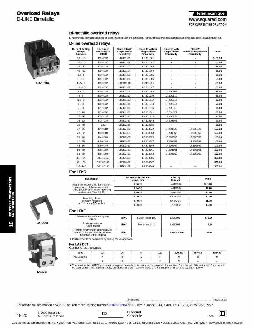
Bi-metallic overload rel aysLR*D overload relays are designed for direct mounting to D-line contactors. To mount these overloads separately see Page 15-33 for separate mount kits.
D-line overload rel aysCurrent Setting
RangeAmperes
For directmounting to
LC1kkk
Class 10 withSingle Phase
Sensitivity
Class 10 withoutSingle Phase
Sensitivity
Class 20 withSingle Phase
Sensitivity
Class 20 without Single Phase
SensitivityPrice
.10 - .16 D09-D32 LR2D1301 LR3D1301 - - $ 58.00
.16 - .25 D09-D32 LR2D1302 LR3D1302 - - 58.00
.25 - .40 D09-D32 LR2D1303 LR3D1303 - - 58.00
.40 - .63 D09-D32 LR2D1304 LR3D1304 - - 58.00
.63 - 1 D09-D32 LR2D1305 LR3D1305 - - 58.00
1 - 1.6 D09-D32 LR2D1306 LR3D1306 - - 58.00
1.25 - 2 D09-D32 LR2D13X6 LR3D13X6 - - 58.00
1.6 - 2.5 D09-D32 LR2D1307 LR3D1307 - - 58.00
2.5 - 4 D09-D32 LR2D1308 LR3D1308 LR2D1508 - 58.00
4 - 6 D09-D32 LR2D1310 LR3D1310 LR2D1510 - 58.00
5.5 - 8 D09-D32 LR2D1312 LR3D1312 LR2D1512 - 60.00
7 - 10 D09-D32 LR2D1314 LR3D1314 LR2D1514 - 60.00
9 - 13 D12-D32 LR2D1316 LR3D1316 LR2D1516 - 60.00
12 - 18 D18-D32 LR2D1321 LR3D1321 LR2D1521 - 60.00
17 - 25 D25-D32 LR2D1322 LR3D1322 LR2D1522 - 60.00
23 - 32 D25-D32 LR2D2353 LR3D2353 LR2D2553 - 71.00
30 - 40 D32 LR2D2355 LR3D2355 - - 71.00
17 - 25 D40-D80 LR2D3322 LR3D3322 LR2D3522 LR3D3522 103.00
23 - 32 D40-D80 LR2D3353 LR3D3353 LR2D3553 LR3D3553 103.00
30 - 40 D40-D80 LR2D3355 LR3D3355 LR2D3555 LR3D3555 103.00
37 - 50 D50-D80 LR2D3357 LR3D3357 LR2D3557 LR3D3557 103.00
48 - 65 D50-D80 LR2D3359 LR3D3359 LR2D3559 LR3D3559 103.00
55 - 70 D65-D80 LR2D3361 LR3D3361 LR2D3561 LR3D3561 123.00
63 - 80 D65-D80 LR2D3363 LR3D3363 LR2D3563 LR3D3563 123.00
80 - 104 D115-D150 LR2D4365 LR3D4365 — — 350.00
95 - 120 D115-D150 LR2D4367 LR3D4367 — — 350.00
110 - 140 D115-D150 LR2D4369 LR3D4369 — — 350.00
Dimensions. . . . . . . . . . . . . . . . . . . . . . . . . . . . . . . . . . . . . . . . . . . . . . . . . . . . . . . . . Pages 15-33
LR2D23kk
Overload RelaysD-LINE Bimetallic
t Part number to be completed by adding coil voltage code.
c The time that the LA7D03 can remain energized depends on its rest time; 1 s pulse wth 9 s rest time; 5 s pulse with 30 s rest time; 10 s pulse with 90 seconds rest time; maximum pulse duration of 20 s with rest time of 300 s. Consumption on inrush and sealed : < 100 VA
For LR kD
Description For use with overloadrelays, type
Catalog Number Price
Separate mounting kits for snap-on mounting on 35 mm omega rail
(AM1 DP200) or for screw mountingcenters, see Page 15-33.
LRkD1 LA7D1064 $ 8.40
LRkD2 LA7D2064 12.70
LRkD3 LA7D3064 16.90
Mounting platesfor screw mounting
at 110 mm (4.3") centers
LRkD1 DX1AP25 10.60
LRkD2 DX1AP26 11.60
LRkD3 LA7D902 15.80
For LR kDReference holder/marking strip
clip-on LRkD Sold in lots of 100 LA7D903 $ 3.20
Locking device for “Stop” button LRkD Sold in lots of 10 LA7D901 2.10
Remote reset/remote tripping deviceMount on right of overload for reset
Mount on left for trippingLRkD LA7D03 t c 42.20
For LA7 D03Control circuit voltages
Volts 12 24 48 110 220/230 380/400 415/440
AC 50/60 Hz J B E F M Q N
DC J B E F M – –
For additional information about D-Line, reference catalog number 8502CT9704 or D-Fax™ number 1614, 1709, 1714, 1736, 2275, 2276,2277.
LA7D03
LA7D901
Courtesy of Steven Engineering, Inc. ! 230 Ryan Way, South San Francisco, CA 94080-6370 ! Main Office: (650) 588-9200 ! Outside Local Area: (800) 258-9200 ! www.stevenengineering.com
15-21I12 DiscountSchedule3/00
15IE
C S
TY
LE
CO
NT
AC
TO
RS
AN
D S
TA
RT
ER
S
© 2000 Square DAll Rights Reserved
Dimensions . . . . . . . . . . . . . . . . . . . . . . . . . . . . . . . . . . . . . . . . . . . . . . . . . .Pages 15-23 – 15-33Accessories . . . . . . . . . . . . . . . . . . . . . . . . . . . . . . . . . . . . . . . . . . . . . . . . . . .Pages 15-7 – 15-11
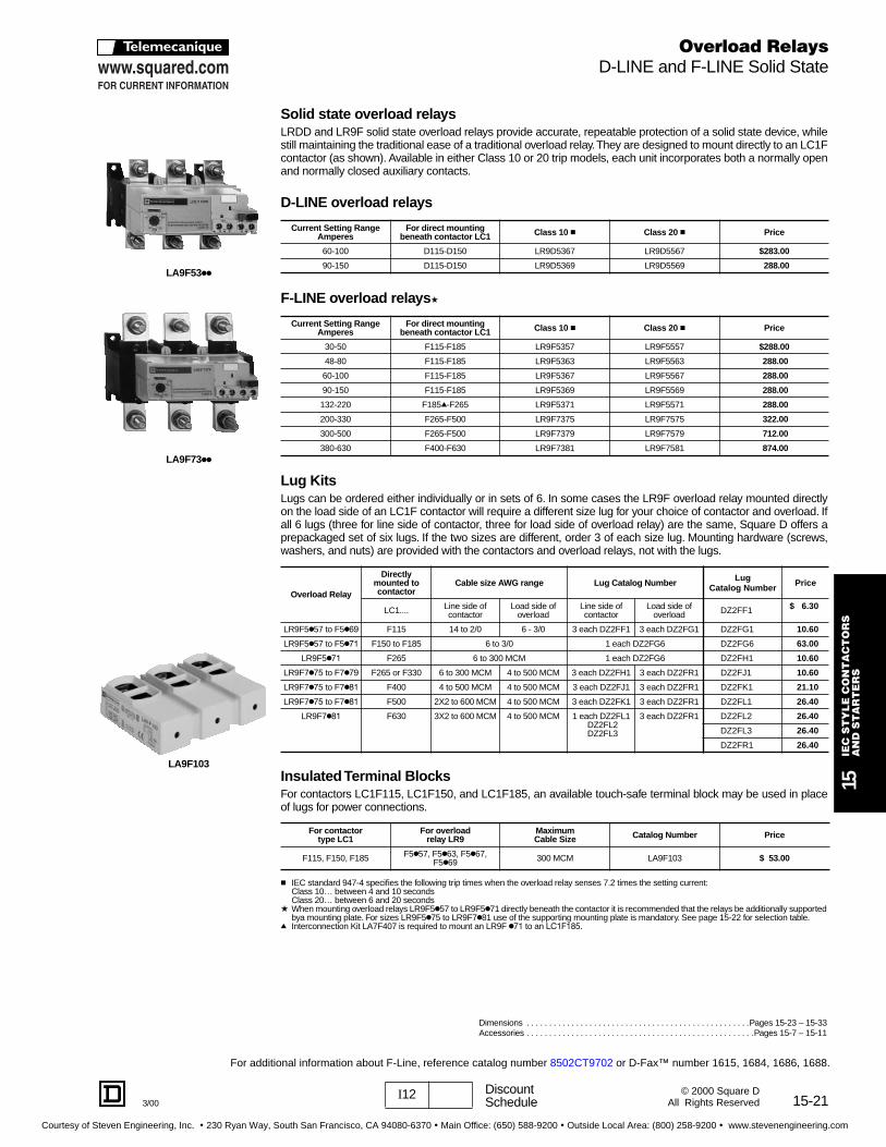
Solid state overload rel aysLRDD and LR9F solid state overload relays provide accurate, repeatable protection of a solid state device, whilestill maintaining the traditional ease of a traditional overload relay. They are designed to mount directly to an LC1Fcontactor (as shown). Available in either Class 10 or 20 trip models, each unit incorporates both a normally openand normally closed auxiliary contacts.
D-LINE overload rel ays
F-LINE overload rel aysa
Lug KitsLugs can be ordered either individually or in sets of 6. In some cases the LR9F overload relay mounted directlyon the load side of an LC1F contactor will require a different size lug for your choice of contactor and overload. Ifall 6 lugs (three for line side of contactor, three for load side of overload relay) are the same, Square D offers aprepackaged set of six lugs. If the two sizes are different, order 3 of each size lug. Mounting hardware (screws,washers, and nuts) are provided with the contactors and overload relays, not with the lugs.
Insulated Termina l Blo cksFor contactors LC1F115, LC1F150, and LC1F185, an available touch-safe terminal block may be used in placeof lugs for power connections.
c IEC standard 947-4 specifies the following trip times when the overload relay senses 7.2 times the setting current:Class 10… between 4 and 10 secondsClass 20… between 6 and 20 seconds
a When mounting overload relays LR9F5k57 to LR9F5k71 directly beneath the contactor it is recommended that the relays be additionally supported bya mounting plate. For sizes LR9F5k75 to LR9F7k81 use of the supporting mounting plate is mandatory. See page 15-22 for selection table.
q Interconnection Kit LA7F407 is required to mount an LR9F k71 to an LC1F185.
Current Setting RangeAmperes
For direct mounting beneath contactor LC1 Class 10 c Class 20 c Price
60-100 D115-D150 LR9D5367 LR9D5567 $283.00
90-150 D115-D150 LR9D5369 LR9D5569 288.00
Current Setting RangeAmperes
For direct mounting beneath contactor LC1 Class 10 c Class 20 c Price
30-50 F115-F185 LR9F5357 LR9F5557 $288.00
48-80 F115-F185 LR9F5363 LR9F5563 288.00
60-100 F115-F185 LR9F5367 LR9F5567 288.00
90-150 F115-F185 LR9F5369 LR9F5569 288.00
132-220 F185q-F265 LR9F5371 LR9F5571 288.00
200-330 F265-F500 LR9F7375 LR9F7575 322.00
300-500 F265-F500 LR9F7379 LR9F7579 712.00
380-630 F400-F630 LR9F7381 LR9F7581 874.00
Overload Rel ay
Direct ly mounted to contactor
Cable size AWG range Lug Catalog Number Lug Catalog Number Price
LC1.... Line side of contactor
Load side of overload
Line side of contactor
Load side of overload DZ2FF1 $ 6.30
LR9F5k57 to F5k69 F115 14 to 2/0 6 - 3/0 3 each DZ2FF1 3 each DZ2FG1 DZ2FG1 10.60
LR9F5k57 to F5k71 F150 to F185 6 to 3/0 1 each DZ2FG6 DZ2FG6 63.00
LR9F5k71 F265 6 to 300 MCM 1 each DZ2FG6 DZ2FH1 10.60
LR9F7k75 to F7k79 F265 or F330 6 to 300 MCM 4 to 500 MCM 3 each DZ2FH1 3 each DZ2FR1 DZ2FJ1 10.60
LR9F7k75 to F7k81 F400 4 to 500 MCM 4 to 500 MCM 3 each DZ2FJ1 3 each DZ2FR1 DZ2FK1 21.10
LR9F7k75 to F7k81 F500 2X2 to 600 MCM 4 to 500 MCM 3 each DZ2FK1 3 each DZ2FR1 DZ2FL1 26.40
LR9F7k81 F630 3X2 to 600 MCM 4 to 500 MCM 1 each DZ2FL1DZ2FL2DZ2FL3
3 each DZ2FR1 DZ2FL2 26.40
DZ2FL3 26.40
DZ2FR1 26.40
For contactor type LC1
For overload relay LR9
MaximumCable Size Catalog Number Price
F115, F150, F185 F5k57, F5k63, F5k67, F5k69 300 MCM LA9F103 $ 53.00
For additional information about F-Line, reference catalog number 8502CT9702 or D-Fax™ number 1615, 1684, 1686, 1688.
Overload RelaysD-LINE and F-LINE Solid State
LA9F53kk
LA9F103
LA9F73kk
Courtesy of Steven Engineering, Inc. ! 230 Ryan Way, South San Francisco, CA 94080-6370 ! Main Office: (650) 588-9200 ! Outside Local Area: (800) 258-9200 ! www.stevenengineering.com
15-22
15IE
C S
TY
LE
CO
NT
AC
TO
RS
A
ND
ST
AR
TE
RS
I12 DiscountSchedule 3/00
© 2000 Square DAll Rights Reserved
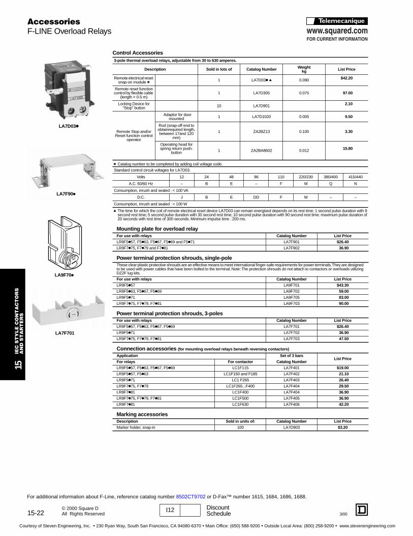
Cont rol Accessories
t Catalog number to be completed by adding coil voltage code.
q The time for which the coil of remote electrical reset device LA7D03 can remain energised depends on its rest time: 1 second pulse duration with 9 second rest time; 5 second pulse duration with 30 second rest time; 10 second pulse duration with 90 second rest time: maximum pulse duration of 20 seconds with rest time of 300 seconds. Minimum impulse time : 200 ms.
3-pole thermal overload rel ays, adjustable f rom 30 to 630 amperes.
Description Sold in lots of Catalog Number Weightkg List Price
Remote electrical reset snap-on module t 1 LA7D03k q 0.090 $42.20
Remote reset function control by flexible cable
(length = 0.5 m)1 LA7D305 0.075 97.00
Locking Device for "Stop" button 10 LA7D901 2.10
Remote Stop and/or Reset function control
operator
Adaptor for door mounted 1 LA7D1020 0.005 9.50
Rod (snap-off end to obtainrequired length, between 17and 120
mm)
1 ZA2BZ13 0.100 3.30
Operating head for spring return push-
button 1 ZA2BA8602 0.012 15.80
Standard control circuit voltages for LA7D03.
Volts 12 24 48 96 110 220/230 380/400 415/440
A.C. 50/60 Hz – B E – F M Q N
Consumption, inrush and sealed : < 100 VA
D.C. J B E DD F M – –
Consumption, inrush and sealed : < 100 W
Mounting plate for overload rel ayFor use with rel ays Catalog Number List Price
LR9F5k57, F5k63, F5k67, F5k69 and F5k71 LA7F901 $26.40
LR9F7k75, F7k79 and F7k81 LA7F902 36.90
Power terminal p rotection sh rouds , single-poleThese clear plastic protective shrouds are an effective means to meet international finger-safe requirements for power terminals. They are designed to be used with power cables that have been bolted to the terminal. Note: The protection shrouds do not attach to contactors or overloads utilizing DZ2F lug kits.
For use with rel ays Catalog Number List Price
LR9F5k57 LA9F701 $43.30
LR9F5k63, F5k67, F5k69 LA9F702 59.00
LR9F5k71 LA9F705 83.00
LR9F7k75, F7k79, F7k81 LA9F703 90.00
Power terminal p rotection sh rouds , 3-polesFor use with rel ays Catalog Number List Price
LR9F5k57, F5k63, F5k67, F5k69 LA7F701 $26.40
LR9F5k71 LA7F702 36.90
LR9F7k75, F7k79, F7k81 LA7F703 47.50
Connection accessories (for mounting overload rel ays beneath r eversing contacto rs)
Application Set of 3 ba rsList Price
For rel ays For contactor Catalog Number
LR9F5k57, F5k63, F5k67, F5k69 LC1F115 LA7F401 $19.00
LR9F5k57, F5k63 LC1F150 and F185 LA7F402 21.10
LR9F5k71 LC1 F265 LA7F403 26.40
LR9F7k75, F7k79 LC1F265...F400 LA7F404 29.50
LR9F7k81 LC1F400 LA7F404 36.90
LR9F7k75, F7k79, F7k81 LC1F500 LA7F405 36.90
LR9F7k81 LC1F630 LA7F406 42.20
Marking accessoriesDescription Sold in units of: Catalog Number List Price
Marker holder, snap-in 100 LA7D903 $3.20
LA9F70k
AccessoriesF-LINE Overload Relays
For additional information about F-Line, reference catalog number 8502CT9702 or D-Fax™ number 1615, 1684, 1686, 1688.
LA7F90k
LA7D03k
LA7F701
Courtesy of Steven Engineering, Inc. ! 230 Ryan Way, South San Francisco, CA 94080-6370 ! Main Office: (650) 588-9200 ! Outside Local Area: (800) 258-9200 ! www.stevenengineering.com
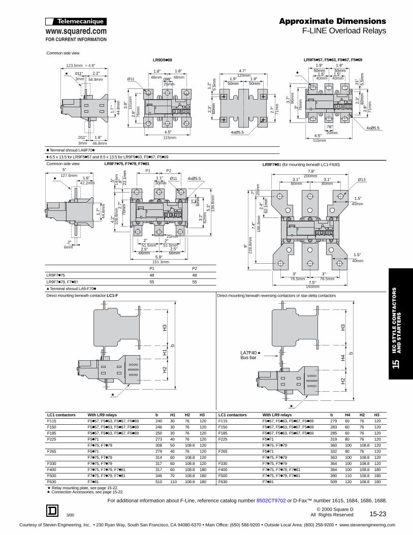
15-233/00
15IE
C S
TY
LE
CO
NT
AC
TO
RS
AN
D S
TA
RT
ER
S
© 2000 Square DAll Rights Reserved
Common side view
LR9D5k69 LR9F5k57, F5k63, F5k67, F5k69
c Terminal shroud LA9F70k
f 6.5 x 13.5 for LR9F5k57 and 8.5 x 13.5 for LR9F5k63, F5k67, F5k69
Common side view LR9F7k75, F7k79, F7k81 LR9F7k81 (for mounting beneath LC1-F630)
P1 P2
LR9F7k75 48 48
LR9F7k79, F7k81 55 55
q Terminal shroud LA9-F70k
Direct mounting beneath contactor LC1-F Direct mounting beneath reversing contactors or star-delta contactors
LC1 contacto rs With LR9 rel ays b H1 H2 H3 LC1 contacto rs With LR9 rel ays b H4 H2 H3
F115 F5k57, F5k63, F5k67, F5k69 240 30 76 120 F115 F5k57, F5k63, F5k67, F5k69 279 60 76 120
F150 F5k57, F5k63, F5k67, F5k69 246 30 76 120 F150 F5k57, F5k63, F5k67, F5k69 283 60 76 120
F185 F5k57, F5k63, F5k67, F5k69 250 30 76 120 F185 F5k57, F5k63, F5k67, F5k69 285 60 76 120
F225 F5k71 273 40 76 120 F225 F5k71 319 80 76 120
F7k75, F7k79 308 50 108.8 120 F7k75, F7k79 360 100 108.8 120
F265 F5k71 279 40 76 120 F265 F5k71 332 90 76 120
F7k75, F7k79 314 60 108.8 120 F7k75, F7k79 363 100 108.8 120
F330 F7k75, F7k79 317 60 108.8 120 F330 F7k75, F7k79 364 100 108.8 120
F400 F7k75, F7k79, F7k81 317 60 108.8 180 F400 F7k75, F7k79, F7k81 364 100 108.8 180
F500 F7k75, F7k79, F7k81 346 70 108.8 180 F500 F7k75, F7k79, F7k81 390 110 108.8 180
F630 F7k81 510 110 108.8 180 F630 F7k81 509 120 108.8 180
a Relay mounting plate, see page 15-22.t Connection Accessories, see page 15-22.
120mm
60m
m
50mm50mm
71m
m
5.5m
m56.8mm
123.5mm = 4.8"
3mm
46.8mm3mm
44.8
mm
(1)
76m
m
25mm
48mm
101m
m
115mm
Ø11
4xØ5.5
2.2"
1.8"
1.7
"
1.8"
48mm
1.8"
.098"
4.5"
1.9" 1.9"
4.7"
1.2"
2.3"
2.7"
.011"
.011"
3.9"
2.9"
c
76m
m
40mm40mm
96m
m
(2)50mm50mm
60m
m
71m
m
5.5m
m
4xØ5.5
115mm
20mm
3.7"
3"
1.9"1.9"
1.5"1.5"
.21"
2.3"
2.8"
4.5"
.78"
f
108.
8mm
14m
m
30mm
P2 P1
151.3mm
Ø11
51.5mm 51.5mm
66mm 66mm
4xØ5.5
70m
m22
.1m
m
6mm
82m
m
136.
8mm
25mm
42.2mm
127.6mm
6mm
44.8
mm
(1)
5"
4.2"
1.6"
.2"
1.7"
2.7"
.8"
.5" 1.1"
.2"
3.2"
5.3"
2"2"
2.5"2.5"
5.9"
q
188.
8mm
20m
m
200mm
80mm80mm
193mm
228.
8mm
76.5mm 76.5mm
62.1
mm
Ø13
40mm
40mm
7.8"
3.1"3.1"
1.5"
1.5"
3" 3"
7.5"
9"
7.4"
2.4"
.7"
H2
b
H3
H1
(1) a
H2
b
H4
(1)
H3
LA7F40 *Bus bar
a
LA7F40 tBus bar
Approximate DimensionsF-LINE Overload Relays
For additional information about F-Line, reference catalog number 8502CT9702 or D-Fax™ number 1615, 1684, 1686, 1688.
Courtesy of Steven Engineering, Inc. ! 230 Ryan Way, South San Francisco, CA 94080-6370 ! Main Office: (650) 588-9200 ! Outside Local Area: (800) 258-9200 ! www.stevenengineering.com

15-24
15IE
C S
TY
LE
CO
NT
AC
TO
RS
A
ND
ST
AR
TE
RS
I11 DiscountSchedule 3/00
© 2000 Square DAll Rights Reserved
The LT6 multifunction relay is for use in applications that demand high level quality and performance, such ascontinusous process and isolated high power motors. This versatile device can be used in a conventional typemotor control circuit configuration or can be directly connected to a personal computer by a serial communicationlink so adjustments can be made remotely.
When used with a local control circuit, the LT6 provides:
– Thermal overload protection by monitoring motor current
– Motor winding overheating protection using PTC type thermistors
– Phase unbalance/phase loss protection
– Ground fault protection
– Thermal overload alarm
When used with a personal computer or Magelis XBT terminal, the motor can be remotely controlled, and thefollowing additional functions are provided:
– Prolonged starting protection
– Locked rotor protection
– Underload (undercurrent) protection
– Power factor monitoring
– Phase reversal protection
q For currents above 25 amperes, a separate current transformer must be used.
Three pole multifunction p rotection rel ays Operational current (amperes) q Catalo g Number Price
0.2-5 LT6P0M005FM $825
5-25 LT6P0M025FM 850
Accessories Description Catalo g Number Price
Configuration software consisting of: • 3 1/2" diskette • 2 meter RS2332 cable
LA9P620 $100
PTC thermistor p robes
Description Nominal operating temperature (˚C) Sold in lots o f Catalog numbe r Price
Integrated triple probe 90 10 DA1TT090 $3.00
110 10 DA1TT110 3.00
120 10 DA1TT120 3.00
130 10 DA1TT130 3.00
140 10 DA1TT140 3.00
150 10 DA1TT150 3.00
160 10 DA1TT160 3.00
170 10 DA1TT170 3.00
Motor Protection UnitsRelays and Accessories
For User’s Manual, reference publication number 9110IM9701.For additional information, reference catalog number 9110CT9702 or D-Fax™ number 1566.
LT6POM005FM
Proof date: 12/22/99, 12:23 P
MM
ake changes: Initials_______________D
ate:____________O
K T
O P
RIN
T: Initials:_______________
Date_____________
Courtesy of Steven Engineering, Inc. ! 230 Ryan Way, South San Francisco, CA 94080-6370 ! Main Office: (650) 588-9200 ! Outside Local Area: (800) 258-9200 ! www.stevenengineering.com

15-25I11 DiscountSchedule3/00
15IE
C S
TY
LE
CO
NT
AC
TO
RS
AN
D S
TA
RT
ER
S
© 2000 Square DAll Rights Reserved
LT3 thermistor protection units continuously monitor the temperature of the machines to be protected (motors, generators, etc.) by means of PTC thermistors embedded in the machine windings. If the nominal operating temperature of the probes is reached, the probes convert the rapid increase in resistance into a switching function which can be used to open the control circuit or signal a fault. Thermistor p rotection rel ays p rovide additional motor p rotection and should be used to supple-ment a co nventional current sensing overload rel ay. The choice of PTC thermistor probe to be incorporated in the motor winding depends on the insulation class, the type of motor and the most suitable location for the probe. This choice is usually made be the motor manufacturer of the motor rewinder, who have all the necessary information.
Protection rel ays (without fault memory) Units with automatic reset without thermistor short circuit detection
Voltage/Frequenc y Output contac t Catalog Number Price
115 VAC - 50/60 Hz 1 N/C LT3SE00F $114
230 VAC - 50/60 Hz 1 N/C LT3SE00M 114
24 VDC 1 N/C LT3SE00BD 114
Units with automatic reset with thermistor short circuit detection fault dignalling indicator
Voltage/Frequenc y Output contac t Catalog Number List Price
230/115 VAC - 50/60 Hz 1 N/O - 1 N/C LT3SA00M $148
24-48 VDC 1 N/O - 1 N/C LT3SA00ED 148
24-230 VAC - 50/60 Hz or 24-230 VDC 2 SPDT LT3SA00MW 148
Protection rel ays (with fault memory) Units with automatic reset without thermistor short circuit detection
Voltage/Frequenc y Output contac t Catalog Number Price
24-48 VAC - 50/60 Hz 1 N/O - 1 N/C LT3SM00E $208
115/230 VAC - 50/60 Hz 1 N/O - 1 N/C LT3SM00M 208
400 VAC - 50/60 Hz 1 N/O - 1 N/C LT3SM00V 208
24-48 VDC 1 N/O - 1 N/C LT3SM00ED 208
24-230 VAC - 50/60 Hz or 24-230 VDC 2 SPDT LT3SM00MW 208
PTC thermistor p robes
Description Nominal operating temperature (˚C) Sold in lots o f Catalog numbe r Price
Integrated triple probe 90 10 DA1TT090 $3.00
110 10 DA1TT110 3.00
120 10 DA1TT120 3.00
130 10 DA1TT130 3.00
140 10 DA1TT140 3.00
150 10 DA1TT150 3.00
160 10 DA1TT160 3.00
170 10 DA1TT170 3.00
Surface probes 60 10 DA1ST060 3.00
70 10 DA1ST070 3.00
80 10 DA1ST080 3.00
90 10 DA1ST090 3.00
100 10 DA1ST100 3.00
Thermistor Protection UnitsRelays and Accessories
For additional information, reference catalog number 9110CT9701 or D-Fax™ number 1565
LT3SE00M
LT3SA00M
LT3SM00M
Dimensions
22.5 1"
100 3.94"
98.4
100
3.94
"
Courtesy of Steven Engineering, Inc. ! 230 Ryan Way, South San Francisco, CA 94080-6370 ! Main Office: (650) 588-9200 ! Outside Local Area: (800) 258-9200 ! www.stevenengineering.com

15-26
15IE
C S
TY
LE
CO
NT
AC
TO
RS
A
ND
ST
AR
TE
RS
3/00© 2000 Square DAll Rights Reserved
LC1 D09, D12
3.03 77
(LA
4 D
A1,
D81
, DE
1)
3.82
*97
(LA
4 D
F, D
T)
4.01
105
*(LA
4 D
M, D
R, D
W, D
Z)
1.7745
.4912.5
(LA8) .4912.5
(LA8)
* with or without combined use of coil suppressor moduleLA4 DA1, DB1, DE1
5.2*132
(LA2, LA3, LA6 DK2)
4.84123
(LA6 DK1)
4.45113
(LA1)
2.91 74
3.1580
* +4mm with lead sealing device * +4mm with lead sealing device
5.39*137
(LA2, LA3, LA6 DK2)
5.04128
(LA6 DK1)
4.64118
(LA1)
2.91 74
3.3485
3.03 77
(LA
4 D
A1,
D81
, DE
1)
3.82
*97
(LA
4 D
F, D
T)
4.01
105
*(LA
4 D
M, D
R, D
W, D
Z)
1.7745
.4912.5
(LA8) .4912.5
(LA8)
* with or without combined use of coil suppressor moduleLA4 DA1, DB1, DE1
LC1 D18
3.42 87
(LA
4 D
A1,
D81
, DE
1)
4.21
*10
7(L
A4
DF
, DT
)
4.53
115
*(LA
4 D
M, D
R, D
W, D
Z)
2.2056
.4912.5
(LA8) .4912.5
(LA8)
* with or without combined use of coil suppressor moduleLA4 DA1, DB1, DE1
5.71*145
(LA2, LA3, LA6 DK2)
5.35136
*(LA6 DK1)
4.96*126
(LA1)
* +4mm with lead sealing device
3.30 84
3.6693
LC1 D25
5.91*150
(LA2, LA3, LA6 DK2)
5.55141
*(LA6 DK1)
5.20*132
(LA1)
* +4mm with lead sealing device
3.30 84
3.8698
3.42 87
(LA
4 D
A1,
D81
, DE
1)
4.21
*10
7(L
A4
DF
, DT
)
4.53
115
*(LA
4 D
M, D
R, D
W, D
Z)
2.2056
.4912.5
(LA8) .4912.5
(LA8)
* with or without combined use of coil suppressor moduleLA4 DA1, DB1, DE1
LC1 D32
*except LA1 DN10, DN01 = 136** +4mm with lead sealing device
5.51
140
5.79
147
(LA
4 D
F, D
T)
6.06
157
(LA
4 D
M, D
R, D
W, D
Z)
(LA
4 D
A2,
DE
2)
3.3485
.4912.5
(LA8) .4912.5
(LA8)(3P)3.7896
(4P)(LA2, LA3, LA6 DK2)
5.75*146
(LA1)
6.50**165
4.49114
LC1 D4011, D5011, D6511 (3P), LC1 D65004 (4P)
5.00
127
5.20
132
5.59
142
(LA
4 D
F, D
T)
5.91
150
(LA
4 D
M, D
R, D
W, D
Z)
2.9575
.4912.5
(LA8) .4912.5
(LA8)
(LA
4 D
A2,
DE
2)
(3P) 3.3485
(4P)
127
5.20
132
5.59
142
(LA
4 D
F, D
T)
5.91
150
(LA
4 D
M, D
R, D
W, D
Z)
2.9575
.4912.5
(LA8) .4912.5
(LA8)(L
A4
DA
2, D
E2)
(3P) 3.3485
(4P)(LA2, LA3, LA6 DK2)
6.02*153
(LA1)
6.77**172
4.92125
5.00
127
*except LA1 DN10, DN01 = 136** +4mm with lead sealing device
LC1 D8011 (3P) D80004 (4P)
5.51
140
5.79
147
(LA
4 D
F, D
T)
6.06
157
(LA
4 D
M, D
R, D
W, D
Z)
(LA
4 D
A2,
DE
2)3.3485
.4912.5
(LA8) .4912.5
(LA8)(3P)3.7896
(4P)
Approximate DimensionsD-LINE Contactors, AC Coil
For additional information about D-Line, reference catalog number 8502CT9704 or D-Fax™ number 1614, 1709, 1714, 1736, 2275, 2276,2277.
Courtesy of Steven Engineering, Inc. ! 230 Ryan Way, South San Francisco, CA 94080-6370 ! Main Office: (650) 588-9200 ! Outside Local Area: (800) 258-9200 ! www.stevenengineering.com
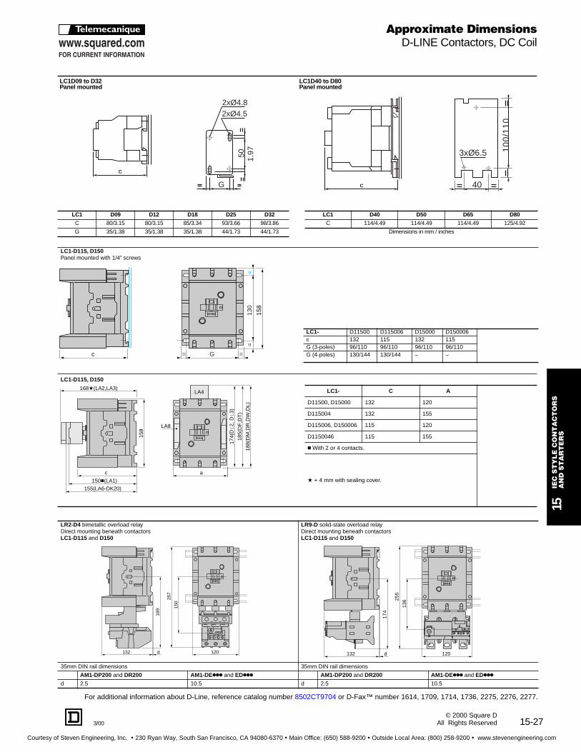
15-273/00
15IE
C S
TY
LE
CO
NT
AC
TO
RS
AN
D S
TA
RT
ER
S
© 2000 Square DAll Rights Reserved
LC1D09 to D32Panel mounted
LC1D40 to D80Panel mounted
LC1 D09 D12 D18 D25 D32 LC1 D40 D50 D65 D80
C 80/3.15 80/3.15 85/3.34 93/3.66 98/3.86 C 114/4.49 114/4.49 114/4.49 125/4.92
G 35/1.38 35/1.38 35/1.38 44/1.73 44/1.73 Dimensions in mm / inches
LC1-D115, D150Panel mounted with 1/4” screws
LC1- D11500 D115006 D15000 D150006c 132 115 132 115G (3-poles) 96/110 96/110 96/110 96/110G (4-poles) 130/144 130/144 – –
LC1-D115, D150
LC1- C A
D11500, D15000 132 120
D115004 132 155
D115006, D150006 115 120
D1150046 115 155
c With 2 or 4 contacts.
a + 4 mm with sealing cover.
LR2-D4 bimetallic overload relay Direct mounting beneath contactors LC1-D115 and D150
LR9-D solid-state overload relay Direct mounting beneath contactors LC1-D115 and D150
35mm DIN rail dimensions 35mm DIN rail dimensions
AM1-DP200 and DR200 AM1-DEkkk and EDkkk AM1-DP200 and DR200 AM1-DEkkk and EDkkk
d 2.5 10.5 d 2.5 10.5
C
2xØ4.82xØ4.5
G
50 1.97 3xØ6.5
40
10
0/1
10
C
130
==
158
c G= =
158
c a
150c(LA1)
155(LA6-DK20)
168a(LA2,LA3)
174(
Di
2, D
i3)
185(
DF
,DT
)
188(
DM
,DR
,DW
,DL)
LA8
LA4
132 d 120
267
150
189
132 120d
174
255
136
Approximate DimensionsD-LINE Contactors, DC Coil
For additional information about D-Line, reference catalog number 8502CT9704 or D-Fax™ number 1614, 1709, 1714, 1736, 2275, 2276, 2277.
Courtesy of Steven Engineering, Inc. ! 230 Ryan Way, South San Francisco, CA 94080-6370 ! Main Office: (650) 588-9200 ! Outside Local Area: (800) 258-9200 ! www.stevenengineering.com

15-28
15IE
C S
TY
LE
CO
NT
AC
TO
RS
AN
D S
TA
RT
ER
S
3/00© 2000 Square DAll Rights Reserved
LP1-D09 to D32Panel mounted
LP1-D40 to D80Panel mounted
.3910
4.53115
5.83 (LA1)148
6.22 (LA6 DK1)158
6.57 (LA3, LA6 DK2)167
2.91 74
+ 4 mm with lead sealing device
.4912.5 (LA8)
.4912.5 (LA8)
1.7745
3.82
(LA
4 D
F, D
T)
97*
4.13
(LA
4 D
M,D
R,D
W,D
Z)
105*
3.03
(LA
4,D
B1,
DC
1,D
E1)
77
*with or without combined use ofcoil suppressor module LA4 DB1,
DC1, DE1
LP1 D09, D12.3910
4.72120
5.98 (LA1)152
6.42 (LA6 DK1)163
6.77 (LA3, LA6 DK2)172
2.91 74
+ 4 mm with lead sealing device
.4912.5 (LA8)
.4912.5 (LA8)
1.7745
3.82
(LA
4 D
F, D
T)
97*
4.13
(LA
4 D
M,D
R,D
W,D
Z)
105*
3.03
(LA
4,D
B1,
DC
1,D
E1)
77
*with or without combined use ofcoil suppressor module LA4 DB1,
DC1, DE1
LP1 D18
.3910
5.12130
3.30 84
6.42 (LA1)163
6.81 (LA6 DK1)173
7.17 (LA2-LA3,LA6 DK2)182
+ 4 mm with lead sealing device
LP1 D25
= =1.7344
.4912..5 (LA8)
.4912..5 (LA8)
2.2056
3.42
(LA
4DB
1,D
C1,
DE
1)87
4.21
*(LA
4 D
F, D
T)
107
4.53
*(LA
4DM
,DR
,DW
,DZ
)11
5
*with or without combined useof coil suppressor module
LA4 DB1, DC1, DE1
LP1 D32
.3910
5.31135
3.30 84
6.81 (LA1)173
7.01 (LA6 DK1)178
7.36 (LA2-LA3,LA6 DK2)187
+ 4 mm with lead sealing device
= =1.7344
.4912..5 (LA8)
.4912..5 (LA8)
2.2056
3.42
(LA
4DB
1,D
C1,
DE
1)87
4.21
*(LA
4 D
F, D
T)
107
4.53
*(LA
4DM
,DR
,DW
,DZ
)11
5
*with or without combined useof coil suppressor module
LA4 DB1, DC1, DE1
LP1 D40, D50, D6511 (3P), LC1D65004 (4P)
2.95(3P),3.34(4P)75,85
5.20
(LA
4 D
C3)
132
5.47
(LA
4 D
F, D
T)
139
5.75
(LA
4 D
M, D
R, D
W, D
Z)
146
.4712 6.73
171
4.96
126
8.03*(LA1)204
8.78 (LA6 DK2, LA2, LA3)223
* except LA1 DN10, DN01 = 136 + 4 mm with lead sealing device
8.27* (LA1)210
9.02 (LA6 DK3, LA2, LA3)223
4.96
126
7.13181
.4712
*except LA1 DN10, DN01 = 143 + 4 mm with lead sealing device
LP1 D8011 (3P), LC1D80004 (4P)
3.34 (3P),3.78(4P)85, 96
5.51
(LA
4 D
C3)
140
5.79
(LA
4 D
F, D
T)
147
6.06
(LA
4 D
M, D
R, D
W, D
Z)
154
C
2XM4
1.97
/2.3
6
2XØ4,5
50
/60
G
3xØ6.5
401.57
10
0/1
10
C
LC1 D09 D12 D18 D25 D32
C 115/4.53 115/4.53 120/4.72 130/5.12 135/5.31
G 35/1.38 35/1.38 35/1.38 50/1.97 50/1.97
LC1 D40 D50 D65 D80
C 171/6.73 171/6.73 171/6.73 181/7.13
Dimensions in mm / inches
Approximate DimensionsD-LINE Contactors, DC Coil
For additional information about D-Line, reference catalog number 8502CT9704 or D-Fax™ number 1614, 1709, 1714, 1736, 2275, 2276,2277.
Courtesy of Steven Engineering, Inc. ! 230 Ryan Way, South San Francisco, CA 94080-6370 ! Main Office: (650) 588-9200 ! Outside Local Area: (800) 258-9200 ! www.stevenengineering.com

15-293/00
15IE
C S
TY
LE
CO
NT
AC
TO
RS
AN
D S
TA
RT
ER
S
© 2000 Square DAll Rights Reserved
LC2-D115 and D150 2 x LC1-D115 and D150 Panel mounted with 1/4” screws
LC2- or 2 x LC1- (3-pole) a c e1 e2 G
D115, D150 266 148 56 18 242/256
LC2- or 2 x LC1- (4-pole) a c e1 e2 G
D115 334 148 - 60 310/324
c, e1 and e2 including cabling
LC2 D09 to D322 x LC1 D09 to D32
c
e1e2
= =Ga
1.97
/2.3
650
/60
==
2 x 4.5 dia.
6
LP2 D09 to D322 x LP1 D09 to D32
C, e1, and e2: include wiring
c
e1e2
(1)
= =G1
6 x 6.5mm dia.
= =1.5740
1.5740
Ga
3.94
/4.3
710
0/11
0.3
1 8.3
1 8
5.0
127
LC2 D40 to D80LP2 D40 to D89
C, e1, and e2: include wiring(1) protective shrouds
158
e1e2c
G
a
= =
130
==
Dimensions sh own in millimete rs (mm X .0394 = inches)
mm/inLC2 D09/D12 D18 D25 D32
a 105/4.14 106/4.18 127/5.00 128/5.04
b 74/2.92 74/2.92 84/3.31 84/3.31
c 84/3.31 92/3.62 99/3.90 117/4.61
e1 3-Pole 4/.016 7/0.28 6/0.24 18/0.71
e2 4-Pole 3/0.12 – 6/0.24 –
G 94/3.70 94/3.70 110-120/4.33-4.73 110-120/4.33-4.73
mm/inLP2 D40/D50/D65 D80
3-Pole 4-Pole 3-Pole 4-Pole
a 165/6.50 182/7.17 182/7.17 207/8.16
c 199/7.84 190/7.49 215//8.47 215/8.47
e1 3-Pole 5/0.20 – 13/0.51 –
e2 4-Pole – 11/0.43 – 20/0.79
G 50/1.97 57/2.25 57/2.25 71/2.80
G1 90/3.55 97/3.82 96/3.78 111/4.37
mm/inLC2 D40/D50/D65 D80
3-Pole 4-Pole 3-Pole 4-Pole
a 165/6.50 182/7.17 182/7.17 207/8.16
c 142/5.59 133/5.24 158/6.63 158/6.23
e1 3-Pole 5/0.20 – 13/0.51 –
e2 4-Pole – 11/0.43 – 20/0.79
G 50/1.97 57/2.25 57/2.25 71/2.80
G1 90/3.55 97/3.82 96/3.78 111/4.37
mm/inLP2 D09/D12 D18 D25 D32
a 105/4.14 106/4.18 127/5.00 128/5.04
b 74/2.92 74/2.92 84/3.31 84/3.31
c 118/4.65 127/5.00 137/5.40 153/6.03
e1 3-Pole 4/.016 7/0.28 6/0.24 18/0.71
e2 4-Pole 3/0.12 – 6/0.24 –
G 95/3.70 95/3.70 110-120/4.33-4.73 110-120/4.33-4.73
Approximate DimensionsD-LINE Reversing Contactors
For additional information about D-Line, reference catalog number 8502CT9704 or D-Fax™ number 1614, 1709, 1714, 1736, 2275, 2276, 2277.
ce1
e2= =G
a
1.97
/2.3
650
/60
==
2 x 4.5 dia.
6
LC2 D09 to D322 x LC1 D09 to D32
C, e1, and e2: include wiring
Courtesy of Steven Engineering, Inc. ! 230 Ryan Way, South San Francisco, CA 94080-6370 ! Main Office: (650) 588-9200 ! Outside Local Area: (800) 258-9200 ! www.stevenengineering.com
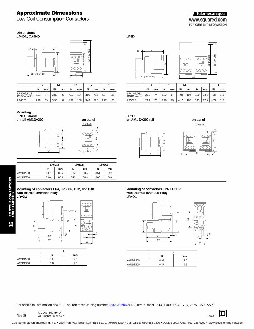
15-30
15IE
C S
TY
LE
CO
NT
AC
TO
RS
AN
D S
TA
RT
ER
S
3/00© 2000 Square DAll Rights Reserved
DimensionsLP4DN, CA4ND
MountingLP4D, CA4DNon rail AM1D k200 on panel
Mounting of contacto rs LP4, LP5D09, D12, and D18with thermal overload rel ayLRkD1
b b1 b2 c c1
IN mm IN mm IN mm IN mm IN mm
LP4D09, D12, D18 Contactor 2.91 74 3.82 97 4.09 104 3.09 78.5 4.37 111
LP4D25 2.99 76 3.90 99 4.17 106 3.43 87.0 4.72 120
c
LPkD12 LPkD18 LPkD25
IN mm IN mm IN mm
AM1DP200 3.17 80.5 3.17 80.5 3.51 89.1
AM1DE200 3.46 88.0 3.46 88.0 3.80 96.6
d
IN mm
AM1DP200 0.08 2.0
AM1DE200 0.37 9.5
c1 (LN1-DN11)
C
b
45
b1
(LA
4 D
T)
b2(L
A4
DM
)10
C
==
60=
=
35= =
2 x Ø 4.5
97
92
47
d
81
50
8
17
44
LP5D
LP5Don AM1 D k200 rail on panel
Mounting of contacto rs LP4, LP5D25with thermal overload rel ayLRkD1
b b1 b2 c c1
IN mm IN mm IN mm IN mm IN mm
LP4D09, D12, D18 Contactor 2.91 74 3.82 97 4.09 104 3.09 78.5 4.37 111
LP5D25 2.99 76 3.90 99 4.17 106 3.43 87.0 4.72 120
d
IN mm
AM1DP200 0.08 2.0
AM1DE200 0.37 9.5
10 c
c1 (LN1 DN11)
b
103
b1(L
A4
DT
)
b1 (
LA4
DM
)
==
C 94= =
60=
=
2 x Ø 4.5
51
97
92
47
d
82
8
17
44
Approximate DimensionsLow Coil Consumption Contactors
For additional information about D-Line, reference catalog number 8502CT9704 or D-Fax™ number 1614, 1709, 1714, 1736, 2275, 2276,2277.
Courtesy of Steven Engineering, Inc. ! 230 Ryan Way, South San Francisco, CA 94080-6370 ! Main Office: (650) 588-9200 ! Outside Local Area: (800) 258-9200 ! www.stevenengineering.com

15-313/00
15IE
C S
TY
LE
CO
NT
AC
TO
RS
AN
D S
TA
RT
ER
S
© 2000 Square DAll Rights Reserved
LC1F11 to F330
LC1F400 to F500
S s1
Q P P Q1a f
M
(1)
L
c(2)
b b2
==
Z= =G1
G Y
J J1 b1=
=
c
q
a
2.2056
X1c
L
8.23
209 b b2
==
8 X 8.5 dia.
G
.9223.5
G1 J
4.7
120
7.09
180
= =
=
=
S 1.4938
M10 X 30 dia.
Q P P Q1a f
M
f
All dimensions shown in mm. To convert to inches multiply by .0394.
f = minimum distance required for coil removal.X1: Minimum clearance according to the operational voltage
and the breaking capacity.
q Protective cover Type LA9F70k.c + 6mm with time delay block (for F115 and F150).a Optimal terminal shroud
f = Minimum distance required for coil removal.X1: Minimum clearance according to the operational voltage and the
breaking capacity.
f Protective cover.
LC1 F115 F150 F185 F265 F330
3 P 4 P 3 P 4 P 3 P 4 P 3 P 4 P 3 P 4 P
a 163.5 200.5 163.5 200.5 168.5 208.5 201.5 243.5 213 261
b 162 162 170 170 174 174 203 203 206 206
b1 137 137 137 137 137 137 145 145 145 145
b2 265 265 301 301 305 305 370 370 375 375
c 165c 165c 165c 165c 176 176 207 207 219 219
f 131 131 131 131 130 130 147 147 147 147
G 106 143 106 143 111 151 142 190 154.5 202.5
G1 80 80 80 80 80 80 96 96 96 96
J 106 106 106 106 106 106 106 106 106 106
J1 120 120 120 120 120 120 120 120 120 120
L 107 107 107 107 113.5 113.5 141 141 145 145
M 147 147 150 150 154 154 178 178 181 181
P 37 37 40 40 40 40 48 48 48 48
Q 29.5 29.5 26.5 26 29 29 39 34 43 43
Q1 60 60 57.5 55.5 59.5 59.5 66.5 66.5 74 74
S 15 15 20 20 20 20 25 25 25 25
S1 27 27 34 34 34 34 38 38 44.5 44.5
Y 44 44 44 44 44 44 38 38 38 38
Z 13.5 13.5 13.5 13.5 13.5 13.5 21.5 21.5 20.5 20.5
Voltage i n V 220/380 415/440 500 660 1000
LC1 F115, F150 20 25 30 40 20
LC1 F185 20 25 30 40 30
LC1 F265 20 25 40 50 40
LC1 F330 25 35 40 50 50
LC1 F400 F500
2 P 3 P 4 P 2 P 3 P 4 P
a 213 213 261 233 233 288
b 206 206 206 238 238 238
b2 375 375 375 400 400 400
c 213 213 213 226 226 226
f 119 119 119 141 141 141
G* 80 80 80 80 80 140
G min. 66 66 66 66 66 66
G max. 102 102 150 120 120 175
G1* 170 170 170 170 170 230
G1 min. 156 156 156 156 156 156
G1 max. 192 192 240 210 210 265
* Supplied
J 19.5 19.5 67.5 39.5 39.5 34.5
L 145 145 145 146 146 146
M 181 181 181 208 208 208
P 48 48 48 55 55 55
Q 69 43 43 76 46 46
Q1 96 74 74 102 77 77
S 25 25 25 30 30 30
Voltage i n V 220/230 415/440 500 660 1000
LC1 F400 30 40 40 50 60
LC1 F500 40 45 50 60 60
Approximate DimensionsF-LINE Contactors
For additional information about F-Line, reference catalog number 8502CT9702 or D-Fax™ number 1615, 1684, 1686, 1688.
Courtesy of Steven Engineering, Inc. ! 230 Ryan Way, South San Francisco, CA 94080-6370 ! Main Office: (650) 588-9200 ! Outside Local Area: (800) 258-9200 ! www.stevenengineering.com
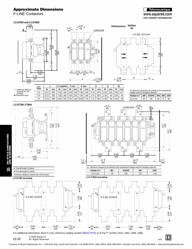
15-32 3/00
15IE
C S
TY
LE
CO
NT
AC
TO
RS
AN
D S
TA
RT
ER
S
© 2000 Square DAll Rights Reserved
18.2
846
4
11.9
730
4
11.0
328
0
2.8372
c
X1
9.85250
6.10155
7.76197
==
9.85250
6.50165
X1
11.0
280
17.0
434
==
3.590
9.45240
9.45240
5.2132
5.00
127
7.09
180
5.00
127
6 X dia. 10.5mm
3.590
9.45240
7.48190
9.45240
5.00
127
7.09
180
5.00
127
8 X dia. 10.5mm
4.0102
2.3860.5
G J1
7.09
180
==
4 X Dia. 10.5 mm
LC1F630 and LC1F800
X1:Minimum clearance according to the operational voltage and the breaking capacity.
Voltage i n V 380 415/440 500 660 1000
X1 in mm 60 60 60 70 80
LC1F780 mounting
f Overall length (3 poles)
a Overall length (4 poles)
*minimum distance required for coil removal.LC1-F7804 mounting
X1: Minimum clearance according to the operational voltage and the breaking capacity.
Voltage i n V 380 415/440 660 1000
X1 in mm 90 100 120 120
LC1F780, F7804
* = minimum distancerequired for coil removal.
c Protective cover.
LC1-F630
a G supplied G min. G max. J1 Q Q1
IN mm IN mm IN mm IN mm IN mm IN mm IN mm
2 P 12.17 309 7.09 180 3.94 100 7.68 195 2.70 68.5 4.02 102 5.00 127
3 P 12.17 309 7.09 180 3.94 100 7.68 195 2.70 68.5 2.36 60 3.50 89
4 P 15.31 389 9.45 240 5.91 150 10.83 275 2.70 68.5 2.36 60 3.50 89
Approximate DimensionsF-LINE Contactors
For additional information about F-Line, reference catalog number 8502CT9702 or D-Fax™ number 1615, 1684, 1686, 1688.
InchesMM
Dimensions
10.4
026
4
1.5740
2.5264
6xM12x45
a
Q Q13.1580
3.1580
7.13*181*
2.360 12xM14x45
1.0226
7.52191
6.30160
6.30160
7.52191
1.02 26
.86
22
13.7
348
15.7
400
27.6 702
33.9 862
7.2*183
7.2*183
f a
Courtesy of Steven Engineering, Inc. ! 230 Ryan Way, South San Francisco, CA 94080-6370 ! Main Office: (650) 588-9200 ! Outside Local Area: (800) 258-9200 ! www.stevenengineering.com
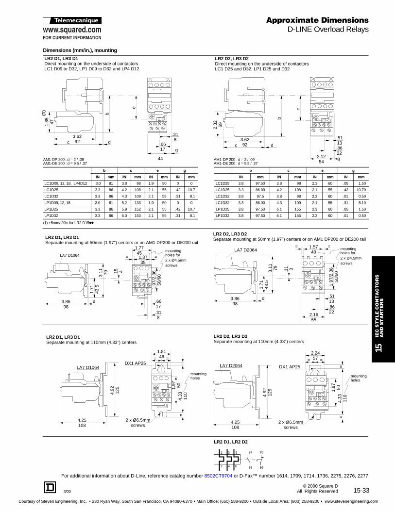
15-333/00
15IE
C S
TY
LE
CO
NT
AC
TO
RS
AN
D S
TA
RT
ER
S
© 2000 Square DAll Rights Reserved
2.32 59
3.6292c d
b
g
.8622
.5113
e
2.1254
LR2 D2, LR3 D2 Direct mounting on the underside of contactorsLC1 D25 and D32, LP1 D25 and D32
3.6292
44
c d
b
g.6617
.318
e
LR2 D1, LR3 D1Direct mounting on the underside of contactorsLC1 D09 to D32, LP1 D09 to D32 and LP4 D12
1.85 47
(1)
LR2 D1, LR2 D2
1 3 5
2 4 6
97 95
98 96
Dimensions (mm/in.) , mounting
(1) +5mm/.20in for LR2 D15kk
AM1-DP 200 : d = 2 / .09AM1-DE 200 : d = 9.5 / .37
b c e g
IN mm IN mm IN mm IN mm
LC1D09, 12, 18, LP4D12 3.0 81 3.8 98 1.9 50 0 0
LC1D25 3.3 86 4.2 108 2.1 55 .42 10.7
LC1D32 3.3 86 4.3 109 2.1 55 .31 8.1
LP1D09, 12, 18 3.0 81 5.2 133 1.9 50 0 0
LP1D25 3.3 86 5.9 152 2.1 55 .42 10.7
LP1D32 3.3 86 6.0 153 2.1 55 .31 8.1
AM1-DP 200 : d = 2 / .09AM1-DE 200 : d = 9.5 / .37
b c e g
IN mm IN mm IN mm IN mm
LC1D25 3.8 97.50 3.8 98 2.3 60 .05 1.50
LC1D25 3.3 86.00 4.2 108 2.1 55 .42 10.70
LC1D32 3.8 97.5 3.8 98 2.3 60 .01 0.50
LC1D32 3.3 86.00 4.3 109 2.1 55 .31 8.10
LP1D25 3.8 97.50 6.1 155 2.3 60 .05 1.50
LP1D32 3.8 97.50 6.1 155 2.3 60 .01 0.50
Approximate DimensionsD-LINE Overload Relays
For additional information about D-Line, reference catalog number 8502CT9704 or D-Fax™ number 1614, 1709, 1714, 1736, 2275, 2276, 2277.
3.11 79
1.71
43.5
.15 4
3.8698
d
LA7 D1604
1.77451.3735
= =
.318
.6617
LR2 D1, LR3 D1Separate mounting at 50mm (1.97") centers or on AM1 DP200 or DE200 rail
1.97
/2.3
650
/60
mounting holes for2 x Ø4.5mmscrews
LA7 D1064
3.8698
d
3.11 79
1.71
43.5
.8622
.5113
2.1655
LA7 D20641.5740
= =
.11 3
LR2 D2, LR3 D2Separate mounting at 50mm (1.97") centers or on AM1 DP200 or DE200 rail
1.97
/2.3
650
/60
mounting holes for2 x Ø4.5mmscrews
4.92
125
4.25108
LA7 D1064DX1 AP25
= =
1.97 50
4.33
110
==
1.8146
LR2 D1, LR3 D1Separate mounting at 110mm (4.33") centers
2 x Ø6.5mmscrews
mounting holes
4.25108
4.92
125
LA7 D2064
1.97 50
4.33
110
==
= =
2.2457
LR2 D2, LR3 D2Separate mounting at 110mm (4.33") centers
DX1 AP25
mounting holes
2 x Ø6.5mmscrews
Courtesy of Steven Engineering, Inc. ! 230 Ryan Way, South San Francisco, CA 94080-6370 ! Main Office: (650) 588-9200 ! Outside Local Area: (800) 258-9200 ! www.stevenengineering.com

15-34
15IE
C S
TY
LE
CO
NT
AC
TO
RS
AN
D S
TA
RT
ER
S
3/00© 2000 Square DAll Rights Reserved
b1 b2
LA7 D093 on LR2, LR3DViewed from the front
1
2
3 5
64
97 95
9698
LR2 D3
mm/inb c e g 3-pole g 4-pole
IN mm IN mm IN mm IN mm IN mm
LC1D40 4.3 111 4.6 119 2.8 72.4 .17 4.5 .37 9.5
LC1D50 4.3 111 4.6 119 2.8 72 4 .17 4.5 – –
LC1D65 4.3 111 4.6 119 2.8 72.4 .17 4.5 .37 9.5
LC1D80 4.5 115.5 4.8 123.4 3 76.9 .37 9.5 .59 15
LP1D40 4.3 111 6.9 176 2.8 72.4 .17 4.5 .37 9.5
LP1D50 4.3 111 6.9 176 2.8 72.4 .17 4.5 – –
LP1D65 4.3 111 6.9 176 2.8 72.4 .17 4.5 .37 9.5
LP1D80 4.5 115.5 7 179.4 3 76.9 .37 9.5 .59 15
Approximate Dimensions D-LINE Overload Relays
For additional information about D-Line, reference catalog number 8502CT9704 or D-Fax™ number 1614, 1709, 1714, 1736, 2275, 2276, 2277.
mm/in b 1 b2
in mm in mm
LR2, LR3D1 1.34 34 1.34 34
LR2, LR3D2 1.14 29 1.18 30
LR2, LR3D3 .83 21 .87 22 2.9575
3 x Ø6.5mmLAD902= =
4.13
105
1.5740
= =
4.96
126
5.00127
LA7D3064
LR2 D3, LE3 D3 Separate mounting at 110 mm (4.33") centers
mounting holes
4.60117
2.02
50.5
1
3.94
100
.07 2
d
2.9575
1.2632
.9523.50
2.95
/3.5
075
/89
LA7-D3064
LR2 D3, LR3 D3 Separate mounting at 50mm (1.97") centers or on AM1-DP200 or DE200 rail
DIN rail AM1-DP 200: d = 2/.07AM1-DE 200: d = 9.5/.37
2 x Ø4.5mmscrews
1.9750 mounting
holes
2.12 54
4.29109
.164
c
b
e
.8321
1.1830
2.7570
g
LR2 D3, LR3 D3Direct mounting on underside of contactorsLC1 D40 to D80 and LP1 D40 to D80
DIN rail AM1-DP 200: d = 2/.07AM1-DE 200: d = 9.5/.37
Courtesy of Steven Engineering, Inc. ! 230 Ryan Way, South San Francisco, CA 94080-6370 ! Main Office: (650) 588-9200 ! Outside Local Area: (800) 258-9200 ! www.stevenengineering.com