AC-G6000DY Diesel Generator - John Deere · Operator’s Manual 5 CARBON MONOXIDE - POISONOUS GAS...
94
37-1046-E/F/S-061311 ©COPYRIGHT 2009, JOHN DEERE CORPORATION® AC-G6000DY Diesel Generator
-
Upload
truongliem -
Category
Documents
-
view
225 -
download
0
Transcript of AC-G6000DY Diesel Generator - John Deere · Operator’s Manual 5 CARBON MONOXIDE - POISONOUS GAS...

Operator’s Manual 137-1046-E/F/S-061311©COPYRIGHT 2009, JOHN DEERE CORPORATION®
AC-G6000DYDiesel Generator

2 Operator’s Manual
IntroductionTHANK YOU for purchasing a John Deere product.READ THIS MANUAL carefully to learn how to operate and service your machine correctly. Failure to do so could result in personal injury or equipment damage. THIS MANUAL SHOULD BE CONSIDERED a permanent part of your machine and should remain with the machine when you sell it.MEASUREMENTS in this manual are given in both metric and customary U.S. unit equivalents. Use only correct replacement parts and fasteners. Metric and inch fasten-ers may require a specific metric or inch wrench.RIGHT HAND AND LEFT HAND sides are determined by facing the motor end of the machine.
The SERIAL NUMBER is located in the Specification or Identification Numbers section. Accurately record all the numbers to help in tracing the machine should it be stolen. Your dealer also needs these numbers when you order parts. File the identification numbers in a secure place off the machine.WARRANTY is provided from your dealer for customers who operate and maintain their equipment as described in this manual. The warranty is explained on the warranty certificate shown in this manual.This warranty provides you the assurance that your dealer will back products where defects appear within the war-ranty period. Should the equipment be abused, or modi-fied to change its performance beyond the original factory specifications, the warranty will become void.
Warning: This product contains lead, a chemical known to the State of California to cause birth defects or other reproductive harm.Wash your hands after handling this product.
PROTECT YOUR INVESTMENT......Use only John Deere Fuel ProtectFuel Stabilizer with Ethanol ProtectionTY27534 or TY27535. Developed to ensure Optimum Performance andProtection.IMPORTANT...Use Year Round!
34-1904 012011

Operator’s Manual 3
Contents Page
Safety ......................................................................... 4
Safety Signs ............................................................. 10
Controls ....................................................................11
Preparing the Generator .......................................... 12
Operation ................................................................. 17
Troubleshooting ....................................................... 21
Service ..................................................................... 22
Storage .................................................................... 26
Specifications ........................................................... 26
Accessoires ................................................................ 27
Warranty ................................................................... 28
All information, illustrations and specifications in this manual are based on the latest information available at the time of publication. The right is
reserved to make changes at any time without notice.

4 Operator’s Manual
WARNING
WARNINGS IN
THE MANUALS.
WARNINGS IN
THE MANUALS.
CAUTION
O CAUTIONS IN
O THE MANUALS
O CAUTIONS IN
O THE MANUALS
O CAUTIONS IN
O THE MANUALS
O CAUTIONS IN
O THE MANUALS
SafetyRECOGNIZE SAFETY INFORMATIONThis is the safety alert symbol. When you see this symbol on your machine or in this manual, be alert to the potential for personal injury.Follow recommended precautions and safe operating prac-tices.
UNDERSTAND SIGNAL WORDSA signal word--DANGER, WARNING or CAUTION--is used with the safety-alert symbol. DANGER identifies the most serious hazards.DANGER or WARNING safety signs are located near specific hazards. General precautions are listed on CAU-TION safety signs. CAUTION also calls attention to safety messages in this manual.
FOLLOW SAFETY INSTRUCTIONSCarefully read all safety messages in this manual and safety signs on your machine. Keep safety signs in good condition. Replace missing or damaged safety signs. Be sure new equipment components and repair parts include the current safety signs. Replacement safety signs are available from your John Deere Customer Service Repre-sentative.Learn how to operate the machine and how to use controls properly. Do not let anyone operate without instruction.Keep your machine in proper working condition. Unauthor-ized modifications to the machine may impair the function and/or safety and affect machine life.If you do not understand any part of this manual and need assistance, contact your John Deere Customer Service Representative.

Operator’s Manual 5
CARBON MONOXIDE - POISONOUS GASUse generator outdoors, away from open windows, vents, or doors.Generator exhaust contains carbon monoxide - a poisonous gas that can kill you. You CAN NOT smell or see this gas.Never use a generator in enclosed or partially-enclosed spaces. Generators can produce high levels of carbon monoxide very quick-ly. When you use a portable generator, remember that you cannot smell or see carbon monoxide. Even if you can’t smell exhaust fumes, you may still be exposed to carbon monoxide.
If you start to feel sick, dizzy, or weak while using a generator, get to fresh air RIGHT AWAY. DO NOT DELAY. The carbon monoxide from generators can rapidly lead to full incapacitation and death. If you experience serious symptoms, get medical attention immedi-ately. Inform medical staff that carbon monoxide poisoning is sus-pected. If you experienced symptoms while indoors, have someone call the fire department to determine when it is safe to re-enter the building.
NEVER operate the generator in an explosive atmosphere, near combustible materials or where ventilation is not sufficient to carry away exhaust fumes. Exhaust fumes can cause serious injury or death.NEVER use a generator indoors, including in homes, garages, basements, crawl spaces, and other enclosed or partially-enclosed areas, even with ventilation. Opening doors and windows or using fans will not prevent carbon monoxide build-up in the home.
Follow the instructions that come with your generator. Locate the unit outdoors and away from doors, windows, and vents that could allow the carbon monoxide gas to come indoors.
ONLY run generator outdoors and away from air intakes.
NEVER run generator inside homes, garages, sheds, or other semi-enclosed spaces. These spaces can trap poisonous gases EVEN IF you run a fan or open doors and windows.
If you start to feel sick, dizzy, or weak while using the generator, shut if off and get fresh air RIGHT AWAY. See a doctor. You may have carbon monoxide poisoning.
Install battery-operated carbon monoxide alarms or plug-in carbon monoxide alarms with battery back-up in your home, according to the manufacturer’s installation instructions. The carbon monoxide alarms should be certified to the requirements of the latest safety standards for carbon monoxide alarms. (UL 2034, IAS 6-96, or CSA 6.19.01).
Test your carbon monoxide alarm frequently and replace dead bat-teries.
6 Operator’s Manual
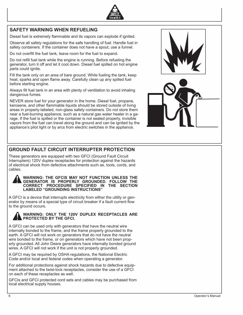
SAFETY WARNING WHEN REFUELINGDiesel fuel is extremely flammable and its vapors can explode if ignited.Observe all safety regulations for the safe handling of fuel. Handle fuel in safety containers. If the container does not have a spout, use a funnel.Do not overfill the fuel tank, leave room for the fuel to expand.Do not refill fuel tank while the engine is running. Before refueling the generator, turn it off and let it cool down. Diesel fuel spilled on hot engine parts could ignite.Fill the tank only on an area of bare ground. While fueling the tank, keep heat, sparks and open flame away. Carefully clean up any spilled fuel before starting engine.Always fill fuel tank in an area with plenty of ventilation to avoid inhaling dangerous fumes.NEVER store fuel for your generator in the home. Diesel fuel, propane, kerosene, and other flammable liquids should be stored outside of living areas in properly-labeled, non-glass safety containers. Do not store them near a fuel-burning appliance, such as a natural gas water heater in a ga-rage. If the fuel is spilled or the container is not sealed properly, invisible vapors from the fuel can travel along the ground and can be ignited by the appliance’s pilot light or by arcs from electric switches in the appliance.
GROUND FAULT CIRCUIT INTERRUPTER PROTECTIONThese generators are equipped with two GFCI (Ground Fault Circuit Interrupters) 120V duplex receptacles for protection against the hazards of electrical shock from defective attachments such as, tools, cords, and cables.
WARNING: THE GFCIS MAY NOT FUNCTION UNLESS THE GENERATOR IS PROPERLY GROUNDED. FOLLOW THE CORRECT PROCEDURE SPECIFIED IN THE SECTION LABELED “GROUNDING INSTRUCTIONS”
A GFCI is a device that interrupts electricity from either the utility or gen-erator by means of a special type of circuit breaker if a fault current flow to the ground occurs.
WARNING: ONLY THE 120V DUPLEX RECEPTACLES ARE PROTECTED BY THE GFCI.
A GFCI can be used only with generators that have the neutral wire internally bonded to the frame, and the frame properly grounded to the earth. A GFCI will not work on generators that do not have the neutral wire bonded to the frame, or on generators which have not been prop-erly grounded. All John Deere generators have internally bonded ground wires. A GFCI will not work if the unit is not properly grounded.A GFCI may be required by OSHA regulations, the National Electric Code and/or local and federal codes when operating a generator. For additional protections against shock hazards due to defective equip-ment attached to the twist-lock receptacles, consider the use of a GFCI on each of these receptacles as well. GFCIs and GFCI protected cord sets and cables may be purchased from local electrical supply houses.
Operator’s Manual 7
ELECTRICAL HAZARDSThis product must be grounded. It has permanent conductor between the generator (stator winding) and the frame. If it should malfunction or breakdown, grounding provides a path of least resistance for electric current to reduce the risk of electric shock.
DANGER - IMPROPER CONNECTION OF THE EQUIPMENT-GROUNDING CONDUCTOR CAN RESULT IN A RISK OF ELECTROCUTION. CHECK WITH A QUALIFIED ELECTRICIAN OR SERVICE PERSON IF YOU ARE INDOUBT AS TO WHETHER THE UNIT IS PROPERLY GROUNDED.
This generator is equipped with a grounding terminal for your protec-tion. Always complete the ground path from the generator to an external ground source as instructed in the section labeled “Grounding Instruc-tions” in the Preparation section of this manual.The generator is a potential source of electrical shock if not kept dry. Keep the generator dry and do not use in rain or wet conditions. To pro-tect from moisture, operate it on a dry surface under an open, canopy-like structure. Dry your hands if wet before touching the generator.Risk of electric shock if you operate this generator with a faulty GFCI (Ground Fault Circuit Interrupter). Test GFCI before each use, see Op-erations Instructions for further information. If GFCI fails test, DO NOT use your generator. Contact your John Deere Customer Service Repre-sentative. Plug appliances directly into the generator. Or, use a heavy duty, out-door-rated extension cord that is rated (in watts or amps) at least equal to the sum of the connected appliance loads. Check that the entire cord is free of cuts or tears and that the plug has all three prongs, especially a grounding pin.NEVER try to power the house wiring by plugging the generator into a wall outlet, a practice known as “back feeding”. This is an extremely dangerous practice that presents an electrocution risk to utility workers and neighbors served by the same utility transformer. It also bypasses some of the built-in household circuit protection devices.If you must connect the generator to the house wiring to power appli-ances, have a qualified electrician install the appropriate equipment in accordance with local electrical codes. Or, check with your utility com-pany to see if it can install an appropriate power transfer switch. For power outages, permanently installed stationary generators are better suited for providing backup power to the home. Even a properly connected portable generator can become overloaded. This may result in overheating or stressing the generator components, possibly leading to a generator failure.

8 Operator’s Manual
IMPORTANT SAFETY INSTRUCTIONSWARNING: To reduce the risk of injury, read this operator’s manual completely before using. When using this product, the following basic precautions should always be followed:
1. Read all the instructions before using the product.2. This product is equipped with a Ground Fault Circuit Interrupter
(GFCI) in the power cord to reduce the risk of electrical shock. If replacement of the plug or cord is needed, use only identical replacement parts.
3. Do not allow children or untrained persons to operate the generator.
4. Do not operate the generator when fatigued or under the influence of drugs or chemicals. Stay alert. Watch what you are doing.
5. Follow the maintenance instructions specified in this manual.
6. When starting the generator, using recoil starter grip, be sure that nothing is in a position to be hit by the operator’s hand or arm.
7. Be sure the switch on electric power tools is in the “OFF” position before plugging them into the generator.
8. Keep the immediate area free of all bystanders.9. Be sure each person who operates this generator is properly
instructed in its safe operation.10. Do not operate the generator or any electrical tool in any
area where water or similar materials constitute an electrical hazard to the operator. Do not operate on wet surfaces, in rain or in snow.
11. Always be sure that the generator is on secure footing so that it cannot slide or shift around, endangering workers.
12. Avoid contacting the hot exhaust manifold, muffler or cylinder(s). Keep clear of all rotating parts.
13. Unless the tool or appliance is double insulated, it must be grounded through a properly grounded receptacle. (See Preparing the Generator, Grounding Instructions). Tools and appliances which have 3 prong plugs must be plugged into extension cords and electrical receptacles with 3 holes. Before operating any electrical item, be sure it is in good repair.
14. Follow instructions in this manual when testing Ground Fault Circuit Interrupter to insure reliable operation.
15. Beware of using this equipment in confined spaces. Confined spaces, without sufficient fresh air ventilation, can contain dangerous gases. Running diesel fuel engines in such environments can lead to deadly explosions and/or asphyxiation.
16. If your generator comes equipped with a transport dolly, make sure this unit is secure during operation and when transporting to prevent unexpected movement or rolling.
17. Use extreme caution when lifting this generator. Do not use dolly handles to lift this generator, use only designated lifting hook to lift this generator. This generator is heavy so proper lifting techniques should be used.
SAVE THESE INSTRUCTIONS
WARNING
WARNINGS IN
THE MANUALS.
WARNINGS IN
THE MANUALS.
CAUTION
O CAUTIONS IN
O THE MANUALS
O CAUTIONS IN
O THE MANUALS
O CAUTIONS IN
O THE MANUALS
O CAUTIONS IN
O THE MANUALS

Operator’s Manual 9
WEAR PROTECTIVE CLOTHINGWear close fitting clothing and safety equipment appropri-ate to the job.Wear a suitable hearing protective device such as earmuffs or earplugs to protect against objectionable or uncomfort-able loud noises.Operating equipment safely requires the full attention of the operator. Do not wear radio or music headphones while operating machine.
INSPECT GENERATORBe sure all covers, guards and shields are tight and in place.Locate all operating controls and safety labels.Inspect power cord for damage before using. There is a hazard of electrical shock from crushing, cutting or heat damage.
PREPARE FOR EMERGENCIESKeep a first aid kit and fire extinguisher handy.Keep emergency numbers for doctors, ambulance ser-vice, hospital and fire department near your telephone.Be prepared if a fire starts.
SERVICE GENERATOR SAFELYBefore servicing the generator, disconnect all equipment and battery (if equipped) and allow unit to cool down.Service generator in a clean dry flat area.

10 Operator’s Manual
SAFETY SIGNS
34-1916-031607-E-F-S.
Using a generator indoors CAN KILL YOU IN MINUTES.
Generator exhaust contains carbon monoxide. This is apoison you cannot see or smell.
NEVER use inside a home or garage, EVEN IF doorsand windows are open.
Only use OUTSIDE and faraway from windows, doors, and vents.
DANGER DANGER PELIGROUtilizando un generador adentro PUEDE MATARLE EN MINUTOS. El escape de generador contiene monóxido de carbono. Este es un gas tóxico que usted no puede ver ni puede oler. Nunca utilice dentro de un hogar ni el garaje, INCLUSO SI puertas y ventanas estén abiertas.Solo utilice AFUERAS y lejos de ventanas abiertas, las puertas, y descargas.
L'utilisation d'un groupe électrogène à l'intérieur PEUT VOUS TUER ENQUELQUES MINUTES.Le gaz d'échappement du groupe électrogène contient de l'oxyde decarbone. C'est un gaz toxique que l'on ne peut pas voir ou sentir.Ne JAMAIS utiliser à l'intérieur d'une maison ou d'un garage, MÊME SI lesportes et fenêtres s'ont ouvertes.N'utiliser qu'à l'EXTÉRIEUR et bien éloignédes fenêtres, portes, et conduits d'aération.
GND34-0889
062104-ENG.
OPERATIONRead unit Operator's Manual carefully before operating this unit. Always make sure unit is level and properly grounded. Check engine oil before starting. START-UP:1. Open fuel valve.2. Move engine speed control to the run position.3. Turn the key to start position, release as soon as it starts.4. Allow unit to warm-up (2 min.) before applying load.5. Turn main breaker ON to main position.SHUT-DOWN:1. Remove all electrical loads by turning off and unplugging cords.2. Turn key to off position.3. Depress stop lever on engine speed control.4. Close fuel valve.*For recoil start see engine manual.
D'UTILISATION OPERACIÓNLire soigneusement le manuel de l'utilisateur avant de se servir de l'appareil. S'assurer toujours que l'appareil est sur une surface plane et qu'il est correctement relié à la terre. Vérifier le niveau d'huile du moteur avant le démarrage. *Pour un démarrage avec lanceur à rappel, voir le manuel du moteur. DEMARRAGE:1. Ouvrir la soupape de carburant de l'appareil ou du moteur.2. Placer la commande de régime du moteur en position de marche. 3. Tourner la clef jusquà la position de démarrage, puis la relâcher dés le démarrage.4. Permettre à l'appareil de tourner pendant deux (2) minutes pour qu'il se réchauffe avant d'appliquer une charge.5. Toumer l’disjoncteur de secteur sur la position marche (ON).ARRET:1. Supprimer toutes les charges électriques en éteignant et en débranchant les raccords électriques.2. Tourner la clef jusqu'à la position d'arrêt.3. Abaisser le levier d'arrêt de la commande de régime du moteur.4. Fermer la soupape de carburant sur l'appareil ou le moteur.
Lea manual de operador antes de operar esta unidad. Siempre asegúrese que unidad sea plana y conecte a tierra correcto. Revise el aceite de motor antes de empezando. *Para arranque de retroceso vea el manual de motor. OPERACIÓN:1. Abra válvula de comestible en unidad o motor.2. Mueva el control de la velocidad de motor a la posición de función. 3. Gire la llave a la posición de arranque, solte tan pronto como lo comienza. 4. Permite 2(min) para calentarse de la unidad antes de aplicando la carga.5. Dble cortacircuitos principal a posició de ON.ARRET:1. Quite todas cargas eléctricas como apagando y desenchufando las cuerdas.2. Gire el interruptor de la llave a la posición de OFF.3. Deprima la palanca de parada en el control de la velocidad de motor.4. Cierre válvula de comestible en unidad o motor.
TEST GFCI RECEPTICAL(S) BEFORE EACH USE. SEE OPERATORS MANUAL FOR INSTRUCTIONS.EXAMINEZ GFCI RECEPTICAL AVANT CHAQUE UTILISATION. VOIR LES OPÉRATEURS MANUELS POUR DES INSTRUCTIONS.PRUEBE GFCI RECEPTICAL ANTES DE CADA USO. VEA A LOS OPERADORES MANUALES PARA LAS INSTRUCCIONES.
NEUTRAL BONDED TO FRAMECOLLÉ NEUTRE À L’ARMATURECONSOLIDADO NEUTRAL AL MARCO
HOURMETERCOMPTEUR HORAIRECONTADOR HORARIO
20 AMPCIRCUIT BREAKER
DISJONCTEURDISYUNTOR
125 VOLT - 20 AMP125 VOLT - 20 AMPÈRE
125 VOLTIO - 20 AMPERIO
20 AMPCIRCUIT BREAKER
DISJONCTEURDISYUNTOR
125 VOLT - 20 AMP125 VOLT - 20 AMPÈRE
125 VOLTIO - 20 AMPERIO
20 AMPCIRCUIT BREAKER
DISJONCTEURDISYUNTOR
MAIN CIRCUIT BREAKERDISJONCTEUR DE SECTEUR
CORTACIRCUITOS PRINCIPAL
125/250 VOLT - 20 AMP125/250 VOLT - 20 AMPÈRE
125/250 VOLTIO - 20 AMPERIO
30 AMPCIRCUIT BREAKER
DISJONCTEURDISYUNTOR
125 VOLT - 30 AMP125 VOLT - 30 AMPÈRE
125 VOLTIO - 30 AMPERIO
34-2324 E-F-S 010908
34-1916
34-1676
34-2324
34-0889
Operator’s Manual 11
ControlsCONTROLS
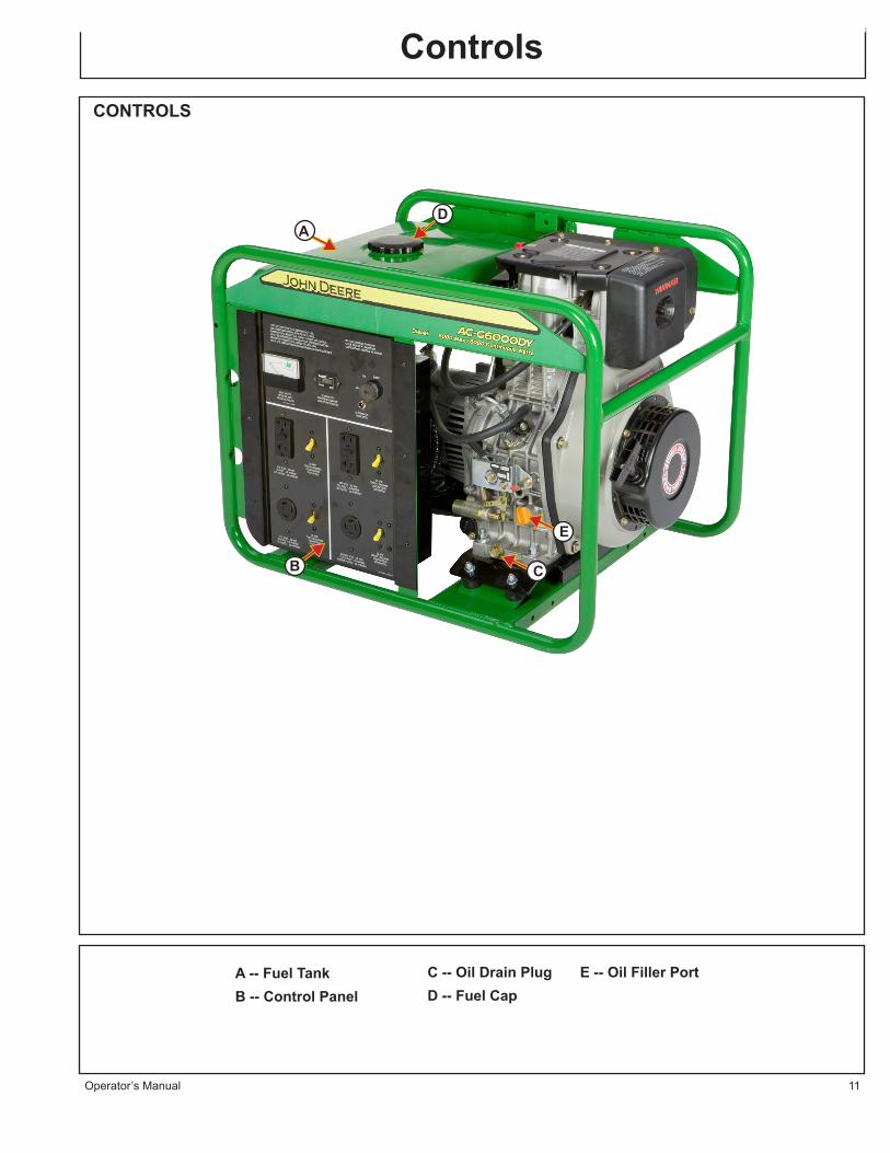
A -- Fuel TankB -- Control Panel
C -- Oil Drain PlugD -- Fuel Cap
D
C
A
B
E -- Oil Filler Port
E
12 Operator’s Manual
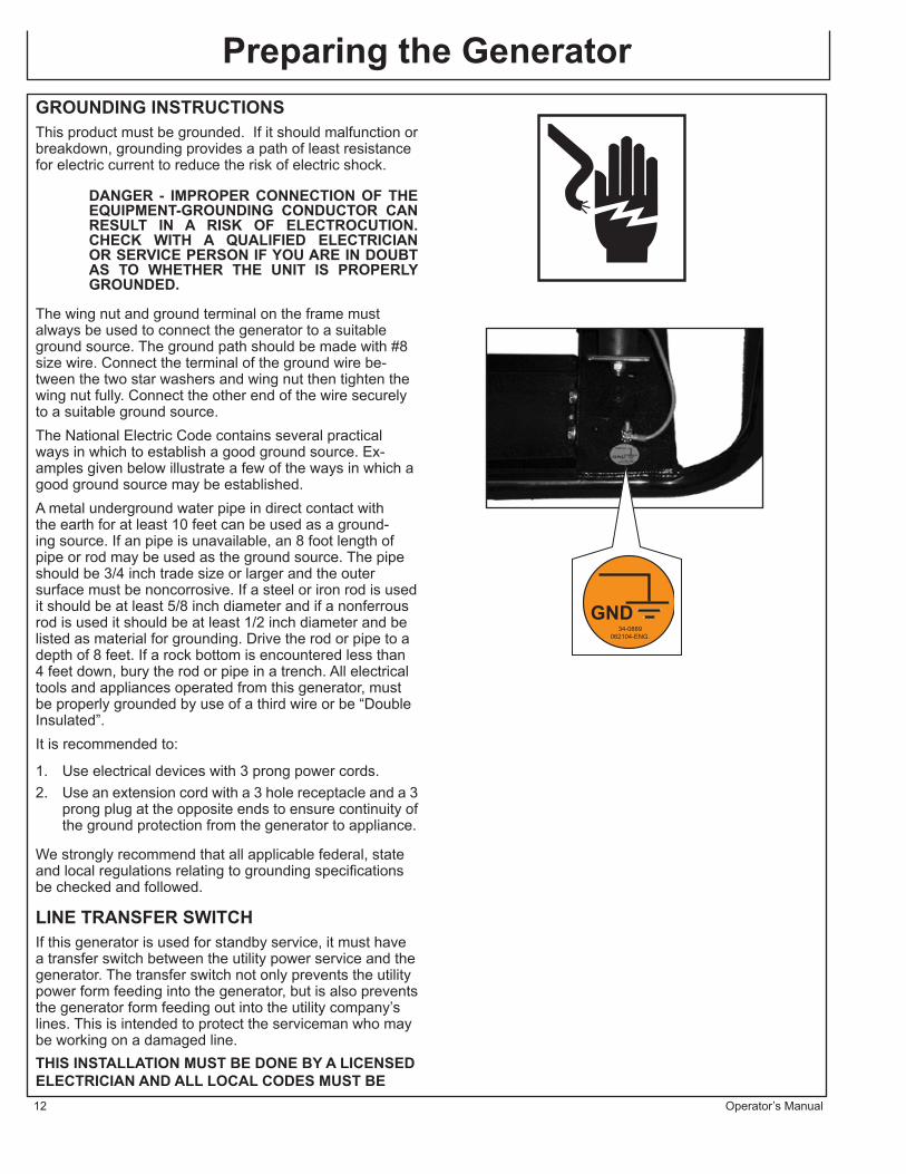
Preparing the GeneratorGROUNDING INSTRUCTIONSThis product must be grounded. If it should malfunction or breakdown, grounding provides a path of least resistance for electric current to reduce the risk of electric shock.
DANGER - IMPROPER CONNECTION OF THE EQUIPMENT-GROUNDING CONDUCTOR CAN RESULT IN A RISK OF ELECTROCUTION. CHECK WITH A QUALIFIED ELECTRICIAN OR SERVICE PERSON IF YOU ARE IN DOUBT AS TO WHETHER THE UNIT IS PROPERLY GROUNDED.
The wing nut and ground terminal on the frame must always be used to connect the generator to a suitable ground source. The ground path should be made with #8 size wire. Connect the terminal of the ground wire be-tween the two star washers and wing nut then tighten the wing nut fully. Connect the other end of the wire securely to a suitable ground source.The National Electric Code contains several practical ways in which to establish a good ground source. Ex-amples given below illustrate a few of the ways in which a good ground source may be established.A metal underground water pipe in direct contact with the earth for at least 10 feet can be used as a ground-ing source. If an pipe is unavailable, an 8 foot length of pipe or rod may be used as the ground source. The pipe should be 3/4 inch trade size or larger and the outer surface must be noncorrosive. If a steel or iron rod is used it should be at least 5/8 inch diameter and if a nonferrous rod is used it should be at least 1/2 inch diameter and be listed as material for grounding. Drive the rod or pipe to a depth of 8 feet. If a rock bottom is encountered less than 4 feet down, bury the rod or pipe in a trench. All electrical tools and appliances operated from this generator, must be properly grounded by use of a third wire or be “Double Insulated”. It is recommended to:
1. Use electrical devices with 3 prong power cords.2. Use an extension cord with a 3 hole receptacle and a 3
prong plug at the opposite ends to ensure continuity of the ground protection from the generator to appliance.
We strongly recommend that all applicable federal, state and local regulations relating to grounding specifications be checked and followed.
LINE TRANSFER SWITCHIf this generator is used for standby service, it must have a transfer switch between the utility power service and the generator. The transfer switch not only prevents the utility power form feeding into the generator, but is also prevents the generator form feeding out into the utility company’s lines. This is intended to protect the serviceman who may be working on a damaged line. THIS INSTALLATION MUST BE DONE BY A LICENSED ELECTRICIAN AND ALL LOCAL CODES MUST BE
GND34-0889
062104-ENG.

Preparing the Generator
Operator’s Manual 13
vFOLLOWED.
ENGINE OIL
CAUTION: ONLY USE THE ENGINE OIL SPECIFIED. OTHER ENGINE OILS MAY AFFECT WARRANTY COVERAGE, CAUSE INTERNAL ENGINE COMPONENTS TO SEIZE, OR SHORTEN ENGINE LIFE.
PREVENT DIRT AND DEBRIS FROM CONTAMINATING THE ENGINE OIL. CAREFULLY CLEAN THE OIL CAP/DIPSTICK AND THE SURROUNDING AREA BEFORE YOU REMOVE THE CAP.
NEVER MIX DIFFERENT TYPES OF ENGINE OIL. THIS MAY ADVERSELY AFFECT THE LUBRICATING PROPERTIES OF THE ENGINE OIL.
NEVER OVERFILL. OVERFILING MAY RESULT IN WHITE EXHAUST SMOKE, ENGINE OVERSPEED OR INTERNAL DAMAGE.
ENGINE OIL SPECIFICATIONSUse an engine oil that meets or exceeds the following guidelines and classifications:
SERVICE CATEGORIES• API Service Categories CD or higher• ACEA Service Categories E-3, E-4, and E-5• JASO (Japanese Automobile Standards Organiza tions)
NOTES:
1. Be sure the engine oil, engine oil storage containers, and engine oil filling equipment are free of sediments and water.
2. Change the engine oil after the first 50 hours of operation and then at every 200 hours thereafter.
3. Select the oil viscosity based on the ambient temperature where the engine is being operated. See SAE Service Grade Viscosity Chart.
4. Yanmar does not recommend the use of engine oil “additives”.
ENGINE OIL VISCOSITYSelect the appropriate engine oil viscosity based on the ambient temperature and use the SAE Service Grade Viscosity Chart.
TO FILL WITH OIL:1. Make sure engine is level.2. Remove oil cap/dipstick from either location and wipe
with clean cloth.3. Add indicated amount of engine oil at either one of the
engine oil filler ports.
°F -4 14 32 50 68 86 104°C -20 -10 0 10 20 30 40
SAE 10W
SAE 20W
SAE 10W-30
SAE 15W-40
SAE 20
SAE 30
SAE 40
TEMPERATURE CHART

Preparing the Generator
14 Operator’s Manual
4. Wait one minute and check oil level.5. Add more oil if necessary.6. Fully reinsert oil cap/dipstick and hand tighten. Over-
tightening the oil cap/dipstick will damage it.
ENGINE OIL CAPACITY (TYPICAL)The following is the engine oil capacity for various Yanmar LV Series engines.
FUELING
WARNING: EXPLOSIVE FUEL!
DIESEL FUEL IS EXTREMELY FLAMMABLE AND ITS VAPORS CAN EXPLODE IF IGNITED.
STORE DIESEL FUEL ONLY IN APPROVED CONTAINERS, IN WELL VENTILATED, UNOCCUPIED BUILDINGS AND AWAY FROM SPARKS OR FLAMES.
DO NOT FILL THE FUEL TANK WHILE THE ENGINE IS HOT OR RUNNING, SINCE SPILLED FUEL COULD IGNITE IF IT COMES IN CONTACT WITH HOT PARTS OR SPARKS FROM IGNITION. DO NOT START THE ENGINE NEAR SPILLED FUEL.
NEVER USE DIESEL FUEL AS A CLEANING AGENT.
WARNING: DO NOT OVERFILL THE FUEL TANK, LEAVE ROOM FOR THE FUEL TO EXPAND.
GENERAL RECOMMENDATIONSPurchase diesel fuel in small quantities and store in clean, approved containers.To minimize gum deposits in your fuel system and to insure easy starting, do not use diesel fuel left over from the previous season.Do not add oil to the diesel fuel.
DIESEL FUEL SPECIFICATIONSDiesel fuel should comply with the following specifications. The table lists several worldwide specifications for diesel fuels.
MODEL # DIPSTICK UPPER LIMIT/ LOWER LIMIT
L100V 1.7/1.06 QT (1.6/1.0L)
Diesel Fuel Specification LocationNo. 2-D, No.1-D, ASTM D975-94 USAEN590:96 European UnionISO 8217 DMX InternationalBS 2869-A1 or A2 United KingdomJIS K2204 Grade No. 2 JapanKSM-2610 KoreaGB252 China
Preparing the Generator
Operator’s Manual 15
ADDITIONAL TECHNICAL FUEL REQUIREMENTS• The fuel cetane number should be equal to 45 or higher.• The sulfur content must not exceed 0.5% by volume Less than 0.05% is preferred.• Bio-Diesel fuels. See below.• Never mix kerosene, used engine oil, or residual fuels with the diesel fuel.• Water and sediment in the fuel should not exceed 0.05% by volume.• Keep the fuel tank and fuel-handling equipment clean at all times.• Poor quality fuel can reduce engine performance and/or cause engine damage.• Fuel additives are not recommended. Some fuel additives may cause poor engine performance. Con sult your Yanmar representative for more informa tion.• Ash content not to exceed 0.01% by volume.• Carbon residue content not to exceed 0.35% by volume. Less than 0.1% is preferred.• Total aromatics content should not exceed 35% by volume. Less than 30% is preferred.• PAH (polycyclic aromatic hydrocarbons) content should be below 10% volume.• Metal content of Na, Mg, Si, and Al should be equal to or lower than 1 mass ppm. (Test analysis method JPI-5S-44-95)
BIO-DIESEL FUELSIn Europe and the United States, as well as some other countries, non-mineral oil based fuel resources such as RME (Rapeseed Methyl Ester) and SOME (Soybean Methyl Ester), collectively known as FAME (Fatty Acid Methyl Esters), are being used as extenders for mineral oil derived diesel fuels.Yanmar approves the use of bio-diesel fuels that do not exceed a blend of 5% (by volume) of FAME with 95% (by volume) of approved mineral oil derived diesel fuel. Such bio-fuels are known in the marketplace as B5 fuels.
These B5 diesel fuels must meet certain require-ments.
1. The bio-fuels must meet the minimum specifications for the country in which they are used.• In Europe, bio-diesel fuels must comply with the European Standard EN14214.• In the United States, bio-fuels must comply with the American Standard ASTM D-6751.
2. Bio-fuels should be purchased only from recognized and authorized diesel fuel suppliers.
PRECAUTIONS AND CONCERNS REGARDING THE USE OF BIO-FUELS:
1. Free methanol in FAME may result in corrosion of aluminum and zinc FIE components.
Preparing the Generator
16 Operator’s Manual
2. Free water in FAME may result in plugging of fuel filters and increased bacterial growth.
3. High viscosity at low temperatures may result in fuel delivery problems, injection pump seizures, and poor injection nozzle spray atomization.
4. FAME may have adverse effect on some elastomers (seal materials) and may result in fuel leakage and dilution of the engine lubricating oil.
5. Even bio-diesel fuels that comply with a suitable standard as delivered, will require additional care and attention to maintain the quality of the fuel in the equipment or other fuel tanks. It is important to maintain a supply of clean, fresh fuel. Regular flushing of the fuel system, and/or fuel storage containers, may be necessary.
6. The use of bio-diesel fuels that do not comply with the standards as agreed to by the diesel engine manufacturers and the diesel fuel injection equipment manufacturers, or bio-diesel fuels that have degraded as per the precautions and concerns above may affect the warranty coverage of your engine.
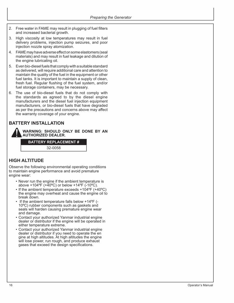
BATTERY INSTALLATION
WARNING: SHOULD ONLY BE DONE BY AN AUTHORIZED DEALER.
HIGH ALTITUDEObserve the following environmental operating conditions to maintain engine performance and avoid premature engine wear:
• Never run the engine if the ambient temperature is above +104ºF (+40ºC) or below +14ºF (-10ºC).• If the ambient temperature exceeds +104ºF (+40ºC) the engine may overheat and cause the engine oil to break down.• If the ambient temperature falls below +14ºF (- 10ºC) rubber components such as gaskets and seals will harden causing premature engine wear and damage.• Contact your authorized Yanmar industrial engine dealer or distributor if the engine will be operated in either temperature extreme.• Contact your authorized Yanmar industrial engine dealer or distributor if you need to operate the en gine at high altitudes. At high altitudes the engine will lose power, run rough, and produce exhaust gases that exceed the design specifications.
BATTERY REPLACEMENT #32-0058

Operator’s Manual 17
OPERATION
RECOIL STARTNOTE: Read Operator’s Manual carefully before
operating this unit. Always make sure the unit is level and properly grounded. Check engine oil before starting.
ELECTRIC START
CAUTION:NEVER USE AN ENGINE STARTING AID SUCH AS ETHER. ENGINE DAMAGE WILL RESULT.
Use the following procedure to start the engine.
1. Make sure the fuel cock is in the ON position. 2. Set engine speed control to RUN
3. Insert the key into the key switch.4. Turn the key clockwise to the START position. Release
the key as soon as the engine starts. It will return to the ON position.
5. If the engine fails to start:
a. Wait until the engine comes to a complete stop before you attempt to start it again. Engaging the starter while the engine is still rotating will result in damage to the starter motor and flywheel.
b. Wait at least 30 seconds before you attempt to start the engine again. This pause will allow the battery voltage to recover to prevent damage to the starter motor due to the low battery voltage.
6. Allow the unit to run for two (2) minute warm-up.7. Turn main breaker to ON position (GEN-6000 units
only). 8. Test the GFCI receptacle(s) on the unit. Push the test
button. The reset button should pop out and there should be no power at the receptacle. Apply a test load or lamp to each receptacle to verify. IF THE RESET BUTTON DOES NOT POP OUT, DO NOT USE THE RECEPTACLES(S). SEE DEALER FOR SERVICE IMMEDIATELY.
9. If GFCI receptacle(s) test correctly, firmly push the reset button to restore power. A distinctive click should be heard or felt when this is complete. IF THE RECEPTACLE(S) DO NOT RESET PROPERLY, DO NOT USE THE RECEPTACLE(S). SEE DEALER FOR SERVICE IMMEDIATELY.
SHUTDOWN
CAUTION: FOR MAXIMUM ENGINE LIFE, YANMAR RECOMMENDS THAT WHEN SHUTTING THE ENGINE DOWN, YOU ALLOW THE ENGINE TO IDLE, WITHOUT LOAD, FOR 5 MINUTES. THIS WILL ALLOW THE ENGINE COMPONENTS THAT OPERATE
Operation

Operating the Generator
18 Operator’s Manual
AT HIGH TEMPERATURES, SUCH AS THE TURBOCHARGER (IF EQUIPPED) AND EXHAUST SYSTEM, TO COOL SLIGHTLY BEFORE THE ENGINE ITSELF IS SHUT DOWN.
Set Engine Speed Control to STOP
CAUTION: IF THE ENGINE CONTINUES TO RUN AFTER YOU POSITION THE ENGINE SPEED CONTROL TO THE STOP POSITION, TURN THE FUEL COCK TO THE CLOSED POSITION.
1. Press the Speed Control knob to STOP and the engine speed control lever will automatically return to the STOP position.Note: The speed control lever is spring -loaded so
when you push down on the STOP button, the speed control lever moves back to the shut-off position. There is no idle position or intermediate speeds.
ELECTRIC START MODELSTurn the key to the OFF position and remove it from the key switch.
AFTER THE ENGINE STOPS
1. Move the fuel cock lever to the closed position.2. Slowly pull the recoil starter handle out to the point of
resistance (the point in the compression stroke where the intake and exhaust valves are closed). This helps to prevent rust while the engine is not in use.
3. If the engine will not be used for six months or longer, follow the additional instructions on storage.
CONTROLS
CONTROL PANEL :The generator is equipped with the following items:
• Hour Meter • Volt Meter • Circuit Breakers• Two 125 Volt, 20 Amp, Duplex (2 outlets), GFCI protected receptacles.• One 125 Volt, 30 Amp, Locking Type Receptacle.• One 125/250 Volt, 20 Amp, Locking Type Recep tacle NOTE: The 125 Volt, 30 Amp and 125/250 Volt, 20
Amp locking receptacles ARE NOT GROUND FAULT PROTECTED. If ground fault protection on these receptacles is necessary or desired, external protection devices must be used. Refer to the section on “Ground Fault Inter-rupter” for more information.

Operating the Generator
Operator’s Manual 19
WARNING: NEVER EXCEED THE RATING OF A RECEPTACLE.
These receptacles are protected against over-loads by resetting magnetic type circuit break-ers. If a circuit breaker trips, the cause should be determined and corrected prior to continu-ing use.
HOUR METER:These generators are equipped with an hour meter that records run time for the unit. This is very useful in sched-uling maintenance. See periodic maintenance chart for suggested maintenance schedule.
VOLT METER: These generators are equipped with a volt meter. The volt meter is used to monitor the unit for proper voltage.
MAIN BREAKER:These generators are equipped with a main circuit break-er which protects the unit in an overload condition. This main breaker must be “ON” for any power to be drawn from the unit.
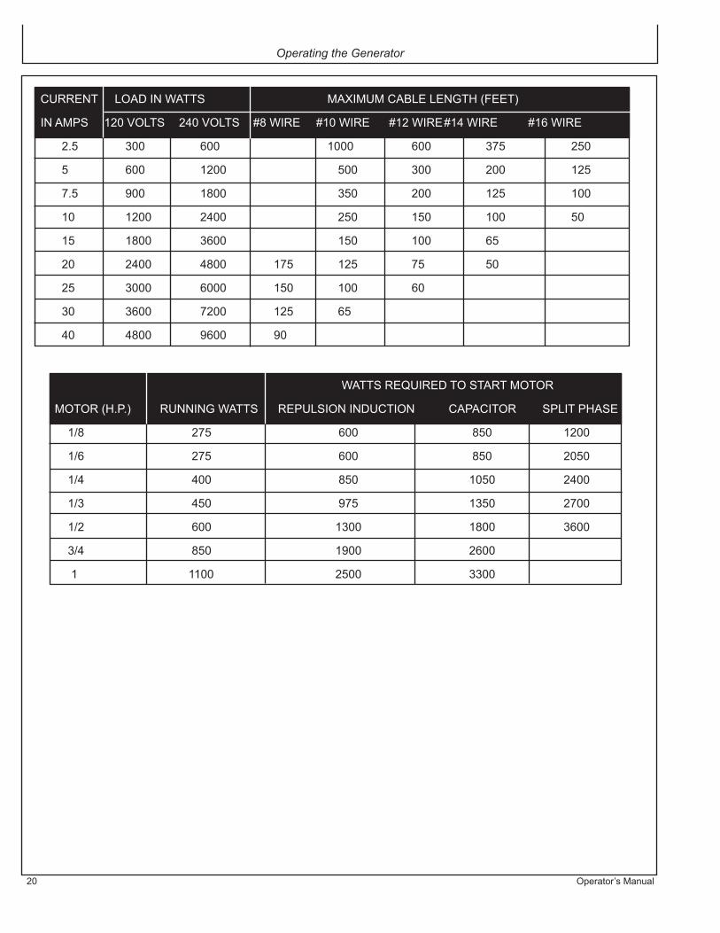
CABLE SIZE:Equipment damage can result from low voltage. There-fore, to prevent excessive voltage drop between the generator and the equipment, the cable should be of adequate gauge for the length used. The cable selection chart gives the maximum cable lengths for various gauges of wire which can adequately carry the loads shown.
ELECTRIC MOTOR LOADS:It is characteristic of common electric motors in normal operation to draw up to six times their running current while starting. This table may be used to estimate the watts required to start “CODE G” electric motors.
CAUTION: IF AN ELECTRIC MOTOR FAILS TO START OR REACH RUNNING SPEED, TURN OFF THE APPLIANCE OR TOOL IMMEDIATELY TO AVOID EQUIPMENT DAMAGE. ALWAYS CHECK THE REQUIREMENTS OF THE TOOL OR APPLIANCE BEING USED COMPARED TO THE RATED OUTPUT OF THE GENERATOR.
Operating the Generator
20 Operator’s Manual
CURRENT LOAD IN WATTS MAXIMUM CABLE LENGTH (FEET)
IN AMPS 120 VOLTS 240 VOLTS #8 WIRE #10 WIRE #12 WIRE #14 WIRE #16 WIRE
2.5 300 600 1000 600 375 250
5 600 1200 500 300 200 125
7.5 900 1800 350 200 125 100
10 1200 2400 250 150 100 50
15 1800 3600 150 100 65
20 2400 4800 175 125 75 50
25 3000 6000 150 100 60
30 3600 7200 125 65
40 4800 9600 90
WATTS REQUIRED TO START MOTOR
MOTOR (H.P.) RUNNING WATTS REPULSION INDUCTION CAPACITOR SPLIT PHASE
1/8 275 600 850 1200
1/6 275 600 850 2050
1/4 400 850 1050 2400
1/3 450 975 1350 2700
1/2 600 1300 1800 3600
3/4 850 1900 2600
1 1100 2500 3300
Operator’s Manual 21
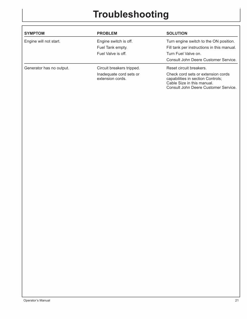
SYMPTOM PROBLEM SOLUTION
Engine will not start. Engine switch is off. Turn engine switch to the ON position. Fuel Tank empty. Fill tank per instructions in this manual. Fuel Valve is off. Turn Fuel Valve on. Consult John Deere Customer Service.
Generator has no output. Circuit breakers tripped. Reset circuit breakers. Inadequate cord sets or Check cord sets or extension cords extension cords. capabilities in section Controls; Cable Size in this manual. Consult John Deere Customer Service.
Troubleshooting

22 Operator’s Manual
GENERATOR MAINTENANCEKeep all air vents clear. Keep the generator clean. DO NOT spray with water.Periodically check all fasteners and tighten, see the periodic maintenance chart.GFCI TEST RECORDS:As with any other safety devices, the GFCIs supplied with these generators must be checked every month to insure that they are functioning properly. To test the GFCIs, follow the instructions and then enter the date of the test below.
1. With the generator running, push the “TEST” button. The “RESET” button should pop out. This should result in the power being off at both outlets of the duplex receptacle. Verify this by plugging a test lamp into each outlet.
WARNING: IF THE RESET BUTTON DOES NOT POP OUT, DO NOT USE THE RECEPTACLE(S). SEE AUTHORIZED JOHN DEERE CUSTOMER SERVICE REPRESENTATIVE FOR SERVICE IMMEDIATELY.
2. If the GFCI test correctly, restore power by FIRMLY pushing the “RESET” button back in until you hear or feel a distinctive “click”. IF THE GFCI FAILS TO RESET PROPERLY, DO NOT USE EITHER OUTLET OF THE DUPLEX RECEPTACLE. Have the unit serviced by an authorized John Deere Customer Service Representative immediately.
3. High vibration or severe mechanical shock loads may cause the GFCIs to trip. IF EITHER GFCI TRIPS BY ITSELF AT ANY TIME, reset it and perform test procedures 1 and 2.
4. Repeat steps 1-3 for the second GFCI.
WARNING: ALTHOUGH THE ABOVE TEST PROCEDURES WILL INDICATE PROPER GFCI OPERATION ON AN UNGROUNDED OR IMPROPERLY GROUNDED GENERATOR, THE GENERATOR MUST STILL BE GROUNDED PER THE GROUNDING INSTRUCTIONS LISTED ON PAGE 12 FOR THE GFCI TO
FUNCTION PROPERLY AND PROTECT THE USER FROM ELECTRICAL FAULTS.
Service
Year Jan. Feb. March April May June July Aug. Sept. Oct. Nov. Dec.
NOTE: Situations exist where a GFCI will not afford any protection against the hazards of electrical shock. EXAMPLE: if a person touches two or more conductors from a damaged cord set and is not in direct contact
with the ground, he or she may receive a shock. Since there is no path to ground for a ground fault current to flow through, the GFCI will not operate and serious injury may result.
The GFCI are merely an added safety feature. There are no substitutes for good safety precautions, correct electrical practices and proper maintenance of cords, equipment and connections.

Operator’s Manual 23
ENGINE:The engine for this generator is governed to operate at speeds close to 3600 RPM (60Hz) throughout the op-erating load range. The no load speed (before a load is applied) will be just a bit higher than the load speed and is normally set to 3750 RPM.
WARNING: DO NOT TAMPER WITH THE GOVERNOR MECHANISM, CHANGE THE SETTING EXPERIMENTALLY, OR PUSH THE THROTTLE OPEN IN AN ATTEMPT TO GENERATE MORE ELECTRICAL CURRENT; EQUIPMENT DAMAGE OR PERSONAL INJURY MAY RESULT.
GOVERNOR SPEED ADJUSTMENT SHOULD BE MADE ONLY BY A JOHN DEERE CUSTOMER SERVICE REPRESENTATIVE.
CHANGING ENGINE OIL:Change oil after initial 50 hours. Thereafter it should be changed every 200 hours of operation.Drain as follows:
1. Make sure the engine is level.2. Start the engine and bring it up to operating
temperature.3. Stop the engine.4. Remove the oil cap/dipstick to allow the engine oil to
drain more easily.5. Position a container under the engine to collect waste
oil.6. Remove the drain plug located on the bottom of the
cylinder block. Allow oil to drain.7. After all oil has been drained from the engine, install the
drain plug and tighten to 14-17 ft lbs.8. Dispose of used oil properly.
TO FILL WITH OIL:
1. Make sure engine is level.2. Remove oil cap/dipstick.3. Add indicated amount of engine oil at either one of the
engine oil filler ports.4. Wait one minute and check oil level.5. Add more oil if necessary.6. Fully reinsert oil cap/dipstick and hand tighten. Over-
tightening the oil cap/dipstick will damage it.
CAUTION: OIL BEING DRAINED MAY BE HOT. TO REDUCE THE RISK OF BURN INJURY, HANDLE WITH CARE. DISPOSE OF USED OIL PROPERLY.
Service
24 Operator’s Manual
Service
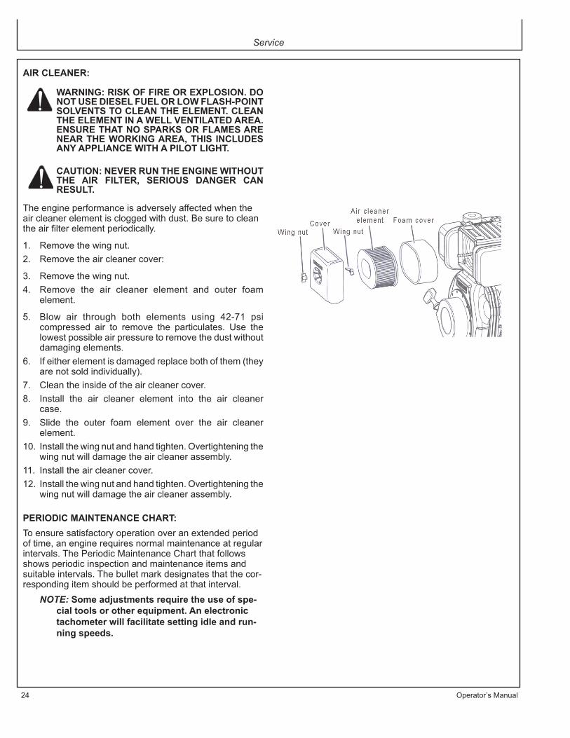
AIR CLEANER:
WARNING: RISK OF FIRE OR EXPLOSION. DO NOT USE DIESEL FUEL OR LOW FLASH-POINT SOLVENTS TO CLEAN THE ELEMENT. CLEAN THE ELEMENT IN A WELL VENTILATED AREA. ENSURE THAT NO SPARKS OR FLAMES ARE NEAR THE WORKING AREA, THIS INCLUDES ANY APPLIANCE WITH A PILOT LIGHT.
CAUTION: NEVER RUN THE ENGINE WITHOUT THE AIR FILTER, SERIOUS DANGER CAN RESULT.
The engine performance is adversely affected when the air cleaner element is clogged with dust. Be sure to clean the air filter element periodically.
1. Remove the wing nut.2. Remove the air cleaner cover:
3. Remove the wing nut.4. Remove the air cleaner element and outer foam
element.
5. Blow air through both elements using 42-71 psi compressed air to remove the particulates. Use the lowest possible air pressure to remove the dust without damaging elements.
6. If either element is damaged replace both of them (they are not sold individually).
7. Clean the inside of the air cleaner cover.8. Install the air cleaner element into the air cleaner
case.9. Slide the outer foam element over the air cleaner
element.10. Install the wing nut and hand tighten. Overtightening the
wing nut will damage the air cleaner assembly.11. Install the air cleaner cover.12. Install the wing nut and hand tighten. Overtightening the
wing nut will damage the air cleaner assembly.
PERIODIC MAINTENANCE CHART:To ensure satisfactory operation over an extended period of time, an engine requires normal maintenance at regular intervals. The Periodic Maintenance Chart that follows shows periodic inspection and maintenance items and suitable intervals. The bullet mark designates that the cor-responding item should be performed at that interval.
NOTE: Some adjustments require the use of spe-cial tools or other equipment. An electronic tachometer will facilitate setting idle and run-ning speeds.

Operator’s Manual 25
Service
Daily Every Every Every Before 25hrs. 100 hrs. 200 hrs. StorageCheck fuel • Check engine oil •Check for loose or lost nuts and bolts •Check for leaks •Check cylinder and head fins for dust and dirt •Check battery electrolyte level •Check fuel lines (replace if necessary) •Clean air cleaner foam element (**) •Tighten nuts and bolts (*) •Change engine oil (*) •Clean fuel filter •Replace air cleaner paper element (**) •Clean dust and dirt from cylinder and cylinder head fins (**) •Add fuel stabilizer •Run unit dry •
* Perform these operations after the first 50 hours of use, then at the recommended intervals.** Service more frequently under dusty conditions.
NOTE: These items must be performed with the proper tools. See your John Deere Customer Service Rep-resentative for service, unless you have the proper equipment and mechanical proficiency.

Service
26 Operator’s Manual
STORING GENERATORSHORT TERM (1-6 MONTHS):1. Add diesel fuel conditioner and stabilizer at the specified concentration.2. Run the unit for two (2) minutes to ensure the mixed fuel is in the entire fuel system. Close the fuel valve and run the
unit until it stops.3. Clean the exterior surface of the generator and apply a rust inhibitor.4. Store the generator in a dry, well ventilated place.LONG TERM (MORE THAN 6 MONTHS):1. Add diesel fuel conditioner and stabilizer at the specified concentration.2. Run the generator until the fuel tank and carburetor is dry.3. Slowly pull the recoil starter handle out to the point of resistance (the point in the compression stroke where the intake
and exhaust valves are closed). This helps to prevent rust while the engine is not in use.4. Clean the exterior surface of the generator and apply a rust inhibitor.5. Store the generator in a dry, well ventilated place.
WARNING: FUEL SHOULD BE DRAINED IN A WELL VENTILATED AREA AND STORED IN A CONTAINER APPROVED FOR DIESEL FUEL.
Storage
SPECIFICATIONSITEM SPECIFICATION AC-G6000DY Engine Yanmar Watts (AC) Rated 5000 watts Watts (AC) Max. 6000 watts Rated Voltage (AC) 120/240V
Max. Amperage 50/25 Cont. Amperage 41.7/20.8
Frequency 60 Hz
Fuel Tank Capacity 2.7 gal. Run Time Hours / Tank of Fuel* 6.5 hrs.
Battery for Electric Start #32-0058
* Rated at 0% Load
NOTE: Unit ratings are established based on operation at standard conditions of 60° F and at sea level. The performance of the generator must be de-rated for temperature and altitude by 1% for every 10° F above 60° F and 3.5% for every 1000 feet above sea level. Due to the operational characteristics of the thermal type circuit breaker, the power available from the generator will decrease slightly with a corresponding increase in ambient temperature.
Due to continuing product improvements, specifications are subject to change without notice.
Specifications

Operator’s Manual 27
Accessories
WHEEL AND HANDLE KIT: AW-5740-0011 Allows easier portability of the generator. The Wheel and Handle Kit includes the wheels, handles, hardware and in-structions needed to assemble the kit to the generator.
LIFTING HOOK KIT: AW-5090-0007Used for lifting the generator safely. The Lifting Hook Kit includes the lifting hook, hardware and instructions needed to assemble the lifting hook to the generator.
RECORD SERIAL NUMBERWrite you model number, machine serial number and date of purchase in the spaces provided below. Your dealer needs this information when ordering parts.
Model No. _______________________________________________
Machine Serial No. ________________________________________
Date of Purchase __________________________________________ (To be filled in by purchaser)

28 Operator’s Manual
Warranty
STATEMENT OF WARRANTY
The manufacturer warrants all parts, (except those referred to below), of your new generator to be free from defects in materials and workmanship during the following periods:
For Two (2) Years from the date of original purchase.
Defective parts not subject to normal wear and tear will be repaired or replaced at our option dur-ing the warranty period. In any event, reimbursement is limited to the purchase price paid.
EXCLUSIONS
1. Engine/Motor and Generator are covered under separate warranty by its respective manufacturer and is subject to the terms set forth therein.
2. This warranty does not cover parts damaged due to normal wear, misapplication, misuse, operation at other than recommended . Failure to follow recommended operating and maintenance procedures also voids warranty.
3. The use of other than genuine manufacturer repair parts will void warranty.4. Parts returned, prepaid to our factory or to an Authorized John Deere Service Center
will be inspected and replaced free of charge if found to be defective and subject to warranty. There are no warranties which extend beyond the description of the face hereof. Under no circumstances shall the manufacturer bear any responsibility for loss of use of the unit, loss of time or rental, inconvenience, commercial loss or consequential damages.
For Service or Warranty Consideration, contactMi-T-M® Corporation, 8650 Enterprise Drive, Peosta, IA 52068
1-877-JD-KLEEN / (1-877-535-5336) Fax 563-556-1235Monday - Friday 8:00 a.m. - 5:00 p.m. CST

Warranty
Operator’s Manual 29
CALIFORNIA EMISSIONS CONTROL WARRANTY STATEMENTYOUR WARRANTY RIGHTS AND OBLIGATIONS
The California Air Resources Board and John Deere are pleased to explain the emissions control system warranty on your small off-road engine (SORE). In California, new SOREs must be designed, built and equipped to meet the State’s stringent anti-smog standards. John Deere must warrant the emissions control system on your SOREs for the periods of time listed below provided there has been no abuse, neglect or improper maintenance of your SOREs.Your emissions control system may include parts such as the carburetor or fuel-injection system, fuel lines and the ignition system. Also included may be hoses, clamps , connectors and other associated components.Where a warrantable condition exist, John Deere will repair your small off-road engine at no cost to you including diagnosis, parts and labor.
MANUFACTURER’S WARRANTY COVERAGE:This emissions control system is warranted for two years. If any emissions-related part on your engine is defective, the part will be repaired or replaced by John Deere.
OWNER’S WARRANTY RESPONSIBILITIES:
-As the SORE owner, you are responsible for performance of the required maintenance listed in your owner’s manual. John Deere recommends that you retain all receipts covering maintenance on your SORE , but John Deere cannot deny warranty solely for the lack of receipts.
-As the SORE owner, you should however be aware that John Deere may deny you warranty coverage if your SORE or a part has failed due to abuse, neglect, or improper maintenance or unapproved modifications.
-You are responsible for presenting your SORE to distribution center or service center authorized by John Deere Corporation, 8650 Enterprise Drive, Peosta, IA 52068 (herein Mi-T-M) as soon as the problem exists. The warranty repairs should be completed in a reasonable amount of time, not to exceed 30 days.
If you have a question regarding your warranty coverage, you should contact John Deere Customer Service Depart-ment at 1-800-553-9053.
Warranty
30 Operator’s Manual
GENERAL EMISSIONS WARRANTY COVERAGE- California Only -
John Deere warrants to the ultimate purchaser and each subsequent purchaser that the SORE (1) has been designed, built and equipped so as to conform with all applicable regulations; and (2) is free from defects in materials and workmanship that cause the failure of a warranted part to conform with those regulations as may be applicable to the terms and conditions stated below.
(a) The warranty period begins on the date the engine is delivered to an ultimate purchaser or first placed into service. The warranty period is two years.(b) Subject to certain conditions and exclusions as stated below, the warranty on emissions related parts is as follows: (1) Any warranted part that is not scheduled for replacement as required maintenance in your owner’s manual is warranted for the warranty period stated above. If the part fails during the period of warranty coverage, the part will be repaired or replaced by John Deere according to subsection (4) below. Any such part repaired or replaced under warranty will be warranted for the remainder of the period. (2) Any warranted part that is scheduled only for regular inspection in your owner’s manual is warranted for the warranty period stated above. Any such part repaired or replaced under warranty will be warranted for the remaining warranty period. (3) Any warranted part that is scheduled for replacement as required maintenance in your owner’s manual is warranted for the period of time before the first scheduled replacement date for that part. If the part fails before the first scheduled replacement, the part will be repaired or replaced by John Deere according to subsection (4) below. Any such part repaired or replaced under warranty will be warranted for the remainder of the period prior to the first scheduled replacement point for the part. (4) Repair or replacement of any warranted part under the warranty provisions herein must be performed at a warranty station at no charge to the owner. (5) Notwithstanding the provisions herein, warranty services or repair will be provided at all of our distribution centers that are franchised to service the subject engines. (6) The owner must not be charged for diagnostic labor that leads to the determination that a warranted part is in fact defective, provided that such diagnostic work is performed at a warranty station. (7) John Deere is liable for damages to other engine components proximity caused by a failure under warranty of any warranted part. (8) Throughout the engine warranty period stated above, John Deere will maintain a supply of warranted parts sufficient to meet the expected demand for such parts. (9) Any replacement part may be used in the performance of any warranty maintenance or repairs and must be provided without charge to the owner. Such use will not reduce the warranty obligations of John Deere. (10) Add-on or modified parts that are not exempted by the Air Resources Board may not be used. The use of any non- exempted add-on or modified parts by the ultimate purchaser will be grounds for disallowing a warranty claims. John Deere will not be liable to warrant failures of warranted parts caused by the use of a non-exempted add-on or modified part.(c) WARRANTED PARTS:The repair or replacement of any warranted part otherwise eligible for warranty coverage may be excluded from such warranty coverage if John Deere demonstrates that the engine has been abused, neglected, or improperly maintained, and that such abuse , neglect ,or improper maintenance was the direct cause of the need for repair or replacement of the part. That notwithstanding, any adjustment of a component that has a factory installed, and properly operating, adjustment limiting device is still eligible for warranty coverage. The following emissions warranty parts list are covered. (1) Fuel Metering System/ (A) Carburetor and internal parts (and/or pressure regulator or fuel injection system)./ (B)Air/fuel ratio feedback and control system, if applicable./ (C) Cold start enrichment system, if applicable./ (D) Regulator assy (gaseous fuel, if applicable) (2) Air Induction System/ (A) Intake manifold, if applicable/ (B) Air filter. (3) Ignition System/ (A) Spark plugs. / (B) Magneto or electronic ignition system. / (C) Spark advance/retard system, if applicable. (4) Exhaust manifold, if applicable (5) Evaporation System / (A) Fuel line / (B) Fuel line fittings

Guide d’utilisation 31
IntroductionMERCI de la confiance témoignée par l’achat d’un produit John Deere.Lire ce manuel attentivement afin de pouvoir utiliser et en-tretenir correctement votre appareil, sinon des dommages corporels ou matériels pourraient en résulter. Ce manuel doit être considéré comme faisant partie inté-grante de votre appareil et doit l’accompagner en cas de revente.LES MESURES dans ce manuel sont indiquées à la fois dans leurs équivalents métriques et en unités usuelles des USA. Utiliser seulement les pièces de rechange et les éléments de fixation corrects. Les éléments de fixa-tion métriques et en pouces peuvent nécessiter des clés spécifiques à leurs système d’unités. Les côtés DROITS ET GAUCHES de l’appareil sont dé-terminés en faisant face au côté moteur de l’appareil.
Le NUMÉRO DE SÉRIE de l’appareil se situe dans la section Caractéristiques ou Numéros d’Identification. Noter correctement tous les numéros afin de faciliter les recherches en cas de vol. Les communiquer également au concessionnaire lors de toute commande de pièces. Ranger les numéros d’identification dans un endroit sûr et séparé de l’appareil.LA GARANTIE fait partie du programme de soutien John Deere destiné aux clients qui utilisent et entretiennent leur équipement tel qu’il est décrit dans ce manuel. Les condi-tions de garantie dont bénéficie cet appareil figurent sur le certificat de garantie dans ce manuel.Cette garantie vous fournit l’assurance que votre conces-sionnaire fournira du support pour les produits où des défauts apparaîtraient au cours de la période de garantie. Toute utilisation abusive de l’équipement ou modifica-tion visant à dépasser les performances spécifiées par le constructeur annuleront la garantie.
AVERTISSEMENT: Ce produit contient du plomb, un produit chimique qui est connu par l'état de Californie comme étant la cause de cancer et demalformations congénitales ou autres effets nocifs de reproduction.Laver vos mains après avoir manipulé ce produit.

32 Guide d’utilisation
Table des matières Page
Sécurité .................................................................... 33
Étiquettes de sécurité .............................................. 34
Commandes ............................................................ 40
Préparation du groupe électrogène ......................... 41
Fonctionnement ....................................................... 47
Dépannage .............................................................. 51
Entretien ................................................................... 52
Remisage ................................................................. 56
Caractéristiques ....................................................... 56
Accessories ................................................................ 57
Garantie .................................................................... 58
Toutes les informations, illustrations et caractéristiques contenues dans la présente publication sont à jour au moment de la publication, le constructeur se réservant le droit d’apporter sans notification toute
modification jugée appropriée.
Guide d’utilisation 33
WARNING
WARNINGS IN
THE MANUALS.
WARNINGS IN
THE MANUALS.
CAUTION
O CAUTIONS IN
O THE MANUALS
O CAUTIONS IN
O THE MANUALS
O CAUTIONS IN
O THE MANUALS
O CAUTIONS IN
O THE MANUALS
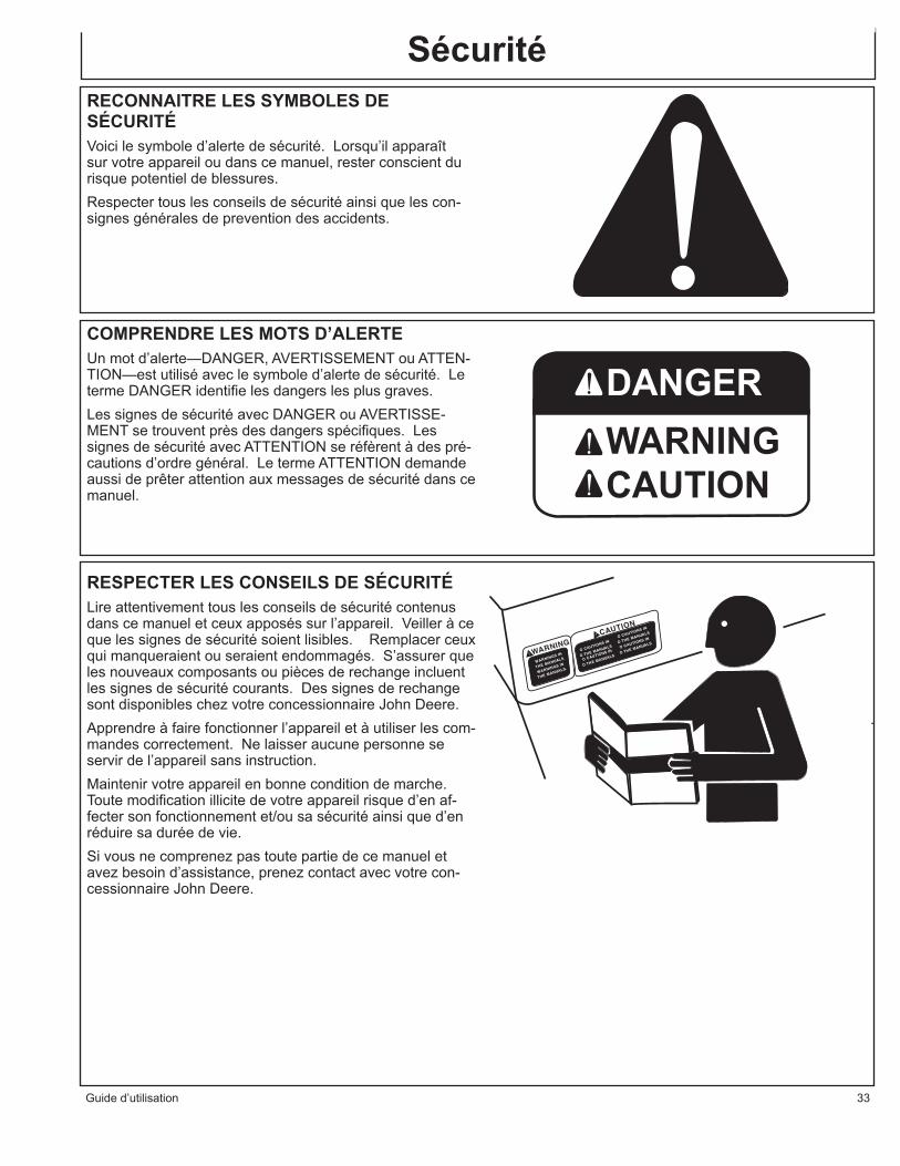
SécuritéRECONNAITRE LES SYMBOLES DE SÉCURITÉVoici le symbole d’alerte de sécurité. Lorsqu’il apparaît sur votre appareil ou dans ce manuel, rester conscient du risque potentiel de blessures.Respecter tous les conseils de sécurité ainsi que les con-signes générales de prevention des accidents.
COMPRENDRE LES MOTS D’ALERTEUn mot d’alerte—DANGER, AVERTISSEMENT ou ATTEN-TION—est utilisé avec le symbole d’alerte de sécurité. Le terme DANGER identifie les dangers les plus graves.Les signes de sécurité avec DANGER ou AVERTISSE-MENT se trouvent près des dangers spécifiques. Les signes de sécurité avec ATTENTION se réfèrent à des pré-cautions d’ordre général. Le terme ATTENTION demande aussi de prêter attention aux messages de sécurité dans ce manuel.
RESPECTER LES CONSEILS DE SÉCURITÉLire attentivement tous les conseils de sécurité contenus dans ce manuel et ceux apposés sur l’appareil. Veiller à ce que les signes de sécurité soient lisibles. Remplacer ceux qui manqueraient ou seraient endommagés. S’assurer que les nouveaux composants ou pièces de rechange incluent les signes de sécurité courants. Des signes de rechange sont disponibles chez votre concessionnaire John Deere.Apprendre à faire fonctionner l’appareil et à utiliser les com-mandes correctement. Ne laisser aucune personne se servir de l’appareil sans instruction.Maintenir votre appareil en bonne condition de marche. Toute modification illicite de votre appareil risque d’en af-fecter son fonctionnement et/ou sa sécurité ainsi que d’en réduire sa durée de vie.Si vous ne comprenez pas toute partie de ce manuel et avez besoin d’assistance, prenez contact avec votre con-cessionnaire John Deere.

34 Operator’s Manual
OXYDE DE CARBONE – GAZ TOXIQUEUtiliser le groupe électrogène dehors, loin de fenêtres ouvertes, de conduits d’aération, ou de portes.Le gaz d’échappement du groupe électrogène contient de l’oxyde de carbone – un gaz toxique qui peut vous tuer. Vous NE POUVEZ PAS sentir ou voir ce gaz.Ne jamais se servir d’un groupe électrogène dans des espaces fermés ou partiellement fermés. Les groupes électrogènes peuvent produire de hauts niveaux d’oxyde de carbone très rapidement. Pendant l’utilisation d’un groupe électrogène portable, se rappeler que vous ne pouvez pas sentir ou voir l’oxyde de carbone. Même si vous ne sentez pas les gaz d’échappement, vous pouvez tout de même être exposé à l’oxyde de carbone.Si vous commencez à vous sentir malade, étourdi, ou faible pendant l’utilisation d’un groupe électrogène, sortez au grand air immédiate-ment. NE PAS ATTENDRE. L’oxyde de carbone provenant des groupes électrogènes peut rapidement être la cause d’une incapaci-té complète ou de mort. En cas des symptômes sérieux, trouver de l’aide médicale im-médiatement. Informer le personnel médical qu’une intoxication à l’oxyde de carbone est possible. Si vos symptômes sont apparus à l’intérieur, ne pas retourner dans le bâtiment avant que les sapeurs pompiers s’assurent que le bâtiment est sans danger.NE JAMAIS utiliser le groupe électrogène dans une atmosphère explosible, près de matériaux combustibles ou dans un endroit où la ventilation n’est pas suffisante pour évacuer les gaz d’échappement. Les gaz d’échappement peuvent être la cause de blessures graves ou de mort.NE JAMAIS se servir d’un groupe électrogène à l’intérieur, que ce soit dans des maisons, garages, sous-sols, vides de comble ou vides sanitaire, et autres espaces fermés ou partiellement fermés, même avec ventilation. Le fait d’ouvrir des fenêtres et des portes ou d’utiliser des ventilateurs n’empêchera pas l’accumulation d’oxyde de carbone dans la maison.Suivre les instructions qui accompagnent votre groupe électrogène. Placer l’appareil dehors et loin des portes, fenêtres, et conduits d’aération qui pourraient permettre au gaz d’oxyde de carbone d’entrer à l’intérieur.Courez SEULEMENT le générateur dehors et loin des entrées d’air. Ne courez jamais le générateur à l’intérieur des maisons, des ga-rages, des hangars, ou d’autres espaces de semi-finale-enclosed. Ces espaces peuvent emprisonner les gaz toxiques MÊME SI vous courez un ventilateur ou ouvrez des portes et des fenêtres.Si vous commencez à vous sentir malade, étourdi, ou faible tout en en utilisant le groupe électrogène, a fermé si au loin et obtient l’air frais TOUT DE SUITE. Voir le docteur. Vous pouvez avoir l’empoisonnement d’oxyde de carbone.Installer des alarmes d’oxyde de carbone à piles ou des alarmes d’oxyde de carbone avec batterie de secours qui se branche dans votre maison, selon les instructions d’installation du fabricant. Les alarmes d’oxyde de carbone doivent être conforme aux exigences des dernières normes de sécurité pour les alarmes d’oxyde de car-bone. (UL 2034, IAS 6-96, ou CSA 6.19.01).Tester votre alarme d’oxyde de carbone fréquemment et remplacer les piles à plat.

Operator’s Manual 35
CONSIGNES DE SÉCURITÉ LORS DU RAVITAILLEMENT EN CARBURANTL’essence est extrêmement inflammable et ses vapeurs peuvent exploser si on l’enflamme.Respecter tous les réglements de sécurité concernant la manipulation sans danger de carburant. Manier le carburant dans des récipients de sécurité. Si le récipient n’a pas de bec, se servir d’un entonnoir.Ne pas trop remplir le réservoir de carburant, laisser toujours de la place pour que le carburant se dilate.Ne jamais remplir le réservoir de carburant lorsque le moteur tourne. Arrêter le groupe électrogène et lui permettre de refroidir avant de le ravitailler en carburant. L’essence renversée sur les parties chaudes du moteur pourrait s’enflammer. Ne remplir le réservoir de carburant que sur une surface nue. Lors du ravitaillement en carburant, écarter le réservoir de toute source de chaleur, d’étincelles ou de flammes nues. Nettoyer soigneusement toute essence renversée avant de démarrer le moteur.Remplir toujours le réservoir de carburant dans un endroit avec une bonne ventilation pour éviter d’inhaler des vapeurs dangereuses.N’entreposer JAMAIS le carburant de votre groupe électrogène dans la maison. L’essence, le propane, le kérosène, et autres liquides inflammables doivent être en-treposés en dehors des espaces habités dans des récipients de sécurité (pas en verre) clairement étiquetés. Ne pas les entreposer près d’un appareil alimenté en combus-tible, tel qu’un chauffe-eau au gaz naturel dans un garage. Si du carburant est renversé ou si le récipient n’est pas fermé correctement, des vapeurs invisibles provenant du carburant peuvent voyager le long du sol et peuvent être enflammées par la veilleuse de l’appareil ou par des arcs des interrupteurs électriques dans l’appareil.
PROTECTION PAR DISJONCTEUR DIFFÉRENTIELCes groupe électrogènes sont équipées de deux prises de courant double de 120V avec disjoncteur différentiel (GFCI) pour offrir de la protection contre les risques de chocs électriques causés par des accessoires défectueux tels que des outils, des cordons ou des câbles.
AVERTISSEMENT : LE DISJONCTEUR DIFFÉRENTIEL RISQUE DE NE PAS FONCTIONNER SI LE GROUPE ÉLECTROGÈNE N’EST PAS CORRECTEMENT RELIÉ À LA TERRE. RESPECTER LA MÉTHODE CORRECTE DE RACCORDE-MENT À LA TERRE QUI EST SPECIFIÉE DANS LA PARTIE INTITULÉE “INSTRUCTIONS DE MISE À LA TERRE.”
Le disjoncteur différentiel est un coupe-circuit spécial qui, en cas de courant parasite al-lant à la terre, coupe le courant venant du secteur ou du groupe électrogène.
AVERTISSEMENT: SEULES LES PRISES DE COURANT DOUBLE DE 120V SONT PROTÉGÉES PAR LE DISJONCTEUR DIFFÉRENTIEL.
Un disjoncteur différentiel (GFCI) ne peut être utilisé qu’avec les groupe électrogènes qui ont le fil neutre relié au châssis en interne et le châssis lui-même correctement mis à la terre. Un disjoncteur différentiel (GFCI) ne marchera pas avec les groupes électrogènes qui n’ont pas le fil neutre relié au châssis en interne, ou avec les groupes électrogènes qui n’ont pas été relié à la terre correctement. Tous les groupes électrogènes John Deere ont des fils de mise à la terre interne. Un disjoncteur différentiel (GFCI) ne fonc-tionnera pas si l’appareil n’est pas relié à la terre correctement.Un disjoncteur différentiel (GFCI) peut être exigé par les réglements de OSHA (loi sur la santé et la sécurité du travail), le Code Electrique Nationale et/ou les codes locaux et fédéraux lors de l’utilisation d’un groupe électrogène.Pour une meilleure protection contre les risques de chocs électriques par de l’équipement défectueux branché sur des prises à verrouillage par rotation, il faut considérer la possi-bilité d’utiliser un disjoncteur différentiel pour chacune de ces prises également.Les disjoncteurs différentiels (GFCI) et les cordons amovibles et câbles protégés par des disjoncteurs différentiels peuvent être achetés dans des magasins locaux de matériel électrique.
36 Operator’s Manual
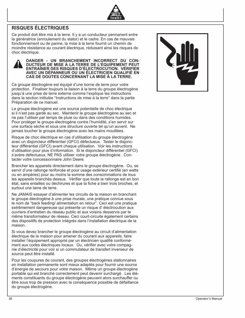
RISQUES ÉLECTRIQUESCe produit doit être mis à la terre. Il y a un conducteur permanent entre la génératrice (enroulement du stator) et le cadre. En cas de mauvais fonctionnement ou de panne, la mise à la terre fournit un chemin de moindre résistance au courant électrique, réduisant ainsi les risques de choc électrique.
DANGER - UN BRANCHEMENT INCORRECT DU CON-DUCTEUR DE MISE À LA TERRE DE L’ÉQUIPEMENT PEUT ENTRAÎNER DES RISQUES D’ÉLECTROCUTION. VÉRIFIER AVEC UN DÉPANNEUR OU UN ÉLECTRICIEN QUALIFIÉ EN CAS DE DOUTES CONCERNANT LA MISE À LA TERRE.
Ce groupe électrogène est équipé d’une borne de terre pour votre protection. Finaliser toujours la liaison à la terre du groupe électrogène jusqu’à une prise de terre externe comme l’explique les instructions dans la section intitulée “Instructions de mise à la terre” dans la partie Préparation de ce manuel.Le groupe électrogène est une source potentielle de choc électrique si il n’est pas gardé au sec. Maintenir le groupe électrogène au sec et ne pas l’utiliser par temps de pluie ou dans des conditions humides. Pour protéger le groupe électrogène contre l’humidité, s’en servir sur une surface séche et sous une structure ouverte tel qu’un auvent. Ne jamais toucher le groupe électrogène avec les mains mouillées.Risque de choc électrique en cas d’utilisation du groupe électrogène avec un disjoncteur différentiel (GFCI) défectueux. Tester le disjonc-teur différentiel (GFCI) avant chaque utilisation. Voir les instructions d’utilisation pour plus d’information. Si le disjoncteur différentiel (GFCI) s’avére défectueux, NE PAS utiliser votre groupe électrogène. Con-tacter votre concessionnaire John Deere.Brancher les appareils directement dans le groupe électrogène. Ou, se servir d’une rallonge renforcée et pour usage extérieur certifié (en watts ou en ampères) pour au moins la somme des consommations de tous les appareils branchés dessus. Vérifier que toute la rallonge est en bon état, sans entailles ou déchirures et que la fiche a bien trois broches, et surtout une lame de terre.Ne JAMAIS essayer d’alimenter les circuits de la maison en branchant le groupe électrogène à une prise murale, une pratique connue sous le nom de “back feeding/ alimentation en retour”. Ceci est une pratique extrêmement dangereuse qui présente un risque d’ électrocution aux ouvriers d’entretien du réseau public et aux voisins desservis par le même transformateur de réseau. Ceci court-circuite également certains des dispositifs de protection intégrés dans l’installation électrique de la maison.Si vous devez brancher le groupe électrogène au circuit d’alimentation électrique de la maison pour amener du courant aux appareils, faire installer l’équipement approprié par un électricien qualifié conformé-ment aux codes électriques locaux. Ou, vérifier avec votre compag-nie d’électricité pour voir si un commutateur de transfert inverseur de source peut être installé.Pour les coupures de courant, des groupes électrogènes stationnaires en installation permanente sont mieux adaptés pour fournir une source d’énergie de secours pour votre maison. Même un groupe électrogène portable qui est branché correctement peut devenir surchargé. Les élé-ments constituants du groupe électrogène peuvent alors surchauffer ou être sous trop de pression avec la conséquence possible de défaillance du groupe électrogène.
Operator’s Manual 37
CONSEILS DE SÉCURITÉ IMPORTANTSAVERTISSEMENT: Pour réduire le risque de blessures, lire ce man-uel de l’utilisateur au complet avant l’utilisation du produit. Pendant l’utilisation de ce produit, les précautions de base suivantes doivent toujours être suivies:1. Lire toutes les instructions avant d’utiliser ce produit.2. Ce produit est muni d’un disjoncteur différentiel (GFCI) dans le
cordon d’alimentation électrique afin de réduire les risques de choc électrique. Si le remplacement du cordon d’alimentation ou de la prise est nécessaire, n’utiliser que des pièces de rechange identiques.
3. Ne pas permettre à des enfants ou à des personnes non qualifiées de se servir de ce groupe électrogène.
4. Ne pas utiliser le groupe électrogène si vous êtes fatigués, en état d’ébriété ou sous l’influence de médicaments ou drogues. Rester vigilant et attentif à vos gestes.
5. Suivre les instructions d’entretien contenues dans ce manuel. 6. Lors du démarrage du groupe électrogène avec le lanceur à rappel,
il faut s’assurer que rien ne risque d’être cogné par la main ou le bras de l’utilisateur.
7. S’assurer que l’interrupteur des outils électriques est en position d’arrêt (OFF) avant de les brancher sur le groupe électrogène.
8. Empêcher l’accés à la zone entourant l’appareil.9. S’assurer que chaque personne utilisant ce groupe électrogène
a reçu une formation adéquate pour le faire fonctionner en toute sécurité.
10. Do not operate the generator or any electrical tool in any 10. Ne pas faire fonctionner le groupe électrogène ou tout outil électrique dans un endroit où de l’eau ou des matiéres semblables entraînent un danger électrique pour l’utilisateur. Ne pas l’utiliser sur des surfaces mouillées, sous la pluie ou sous la neige.
11. S’assurer toujours que le groupe électrogène est bien stable et ne risque en aucun cas de glisser ou de se déplacer, mettant ainsi le personnel en danger.
12. Eviter de toucher le collecteur, le silencieux d’échappement ou le(s) cylindre(s) chaud(s). Se tenir à l’écart de toutes les pièces tournantes.
13. Sauf si l’outil ou l’appareil utilisé est à double isolation, il doit être mis à la terre par une prise correctement mise à la terre. (Voir Préparer le groupe électrogène, Instructions de mise à la terre). Les outils et appareils munis de prises à 3 broches doivent obligatoirement être branchés sur des rallonges et des prises murales à 3 trous. Avant d’utiliser tout appareil électrique, s’assurer qu’il est en bon état.
14. Pour faire l’essai d’un disjoncteur différentiel et assurer sa fiabilité, suivre les instructions de ce manuel.
15. Attention si vous utilisez cet équipement dans des espaces confinés. Les espaces confinés, sans ventilation d’air frais suffisante, risquent de contenir des gaz dangereux. Faire fonctionner un moteur à essence dans de tels cas peut provoquer une explosion et/ou une asphyxie mortelle.
16. Si votre groupe électrogène est équipé d’un chariot de transport, s’assurer que l’appareil est bien stable pendant l’utilisation et le transport afin d’éviter tout mouvement inattendu ou roulement.
17. Faire extrêmement attention en soulevant ce groupe électrogène. Ne pas utiliser les poignées de chariot pour soulever ce groupe électrogène, utiliser uniquement la barre de levage conçue à cet effet. Ce groupe électrogène est lourd et des moyens de levage appropriés doivent être employés.
CONSERVER CES INSTRUCTIONS
WARNING
WARNINGS IN
THE MANUALS.
WARNINGS IN
THE MANUALS.
CAUTION
O CAUTIONS IN
O THE MANUALS
O CAUTIONS IN
O THE MANUALS
O CAUTIONS IN
O THE MANUALS
O CAUTIONS IN
O THE MANUALS
38 Operator’s Manual
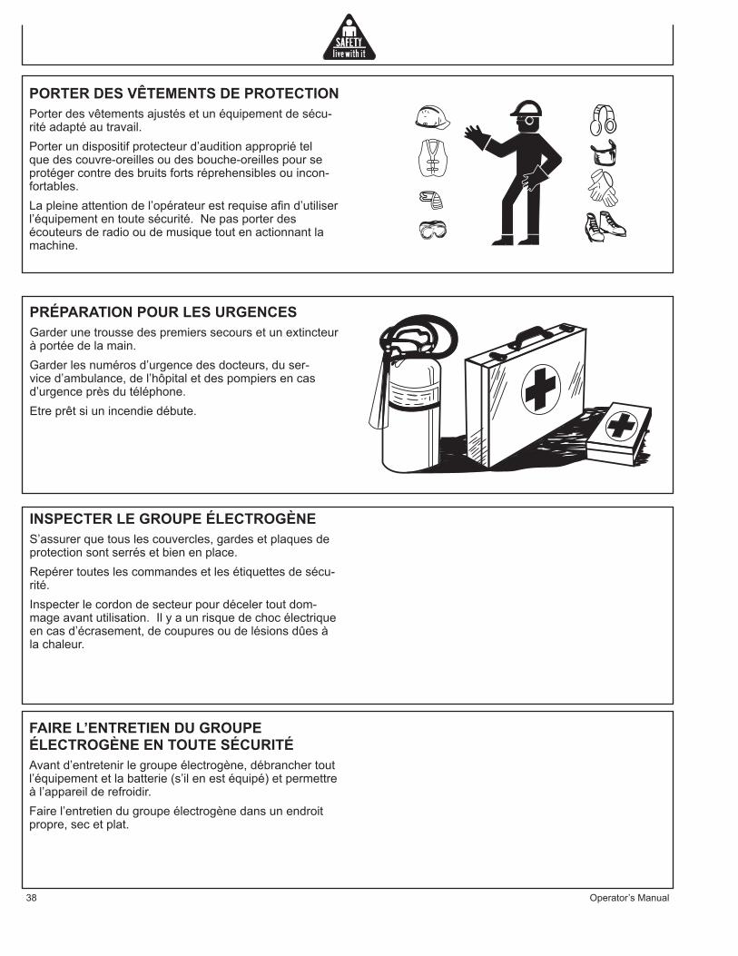
PORTER DES VÊTEMENTS DE PROTECTIONPorter des vêtements ajustés et un équipement de sécu-rité adapté au travail.Porter un dispositif protecteur d’audition approprié tel que des couvre-oreilles ou des bouche-oreilles pour se protéger contre des bruits forts réprehensibles ou incon-fortables. La pleine attention de l’opérateur est requise afin d’utiliser l’équipement en toute sécurité. Ne pas porter des écouteurs de radio ou de musique tout en actionnant la machine.
INSPECTER LE GROUPE ÉLECTROGÈNES’assurer que tous les couvercles, gardes et plaques de protection sont serrés et bien en place.Repérer toutes les commandes et les étiquettes de sécu-rité.Inspecter le cordon de secteur pour déceler tout dom-mage avant utilisation. Il y a un risque de choc électrique en cas d’écrasement, de coupures ou de lésions dûes à la chaleur.
PRÉPARATION POUR LES URGENCES Garder une trousse des premiers secours et un extincteur à portée de la main.Garder les numéros d’urgence des docteurs, du ser-vice d’ambulance, de l’hôpital et des pompiers en cas d’urgence près du téléphone.Etre prêt si un incendie débute.
FAIRE L’ENTRETIEN DU GROUPE ÉLECTROGÈNE EN TOUTE SÉCURITÉAvant d’entretenir le groupe électrogène, débrancher tout l’équipement et la batterie (s’il en est équipé) et permettre à l’appareil de refroidir.Faire l’entretien du groupe électrogène dans un endroit propre, sec et plat.

Operator’s Manual 39
ÉTIQUETTES DE SÉCURITÉ
34-1916-031607-E-F-S.
Using a generator indoors CAN KILL YOU IN MINUTES.
Generator exhaust contains carbon monoxide. This is apoison you cannot see or smell.
NEVER use inside a home or garage, EVEN IF doorsand windows are open.
Only use OUTSIDE and faraway from windows, doors, and vents.
DANGER DANGER PELIGROUtilizando un generador adentro PUEDE MATARLE EN MINUTOS. El escape de generador contiene monóxido de carbono. Este es un gas tóxico que usted no puede ver ni puede oler. Nunca utilice dentro de un hogar ni el garaje, INCLUSO SI puertas y ventanas estén abiertas.Solo utilice AFUERAS y lejos de ventanas abiertas, las puertas, y descargas.
L'utilisation d'un groupe électrogène à l'intérieur PEUT VOUS TUER ENQUELQUES MINUTES.Le gaz d'échappement du groupe électrogène contient de l'oxyde decarbone. C'est un gaz toxique que l'on ne peut pas voir ou sentir.Ne JAMAIS utiliser à l'intérieur d'une maison ou d'un garage, MÊME SI lesportes et fenêtres s'ont ouvertes.N'utiliser qu'à l'EXTÉRIEUR et bien éloignédes fenêtres, portes, et conduits d'aération.
GND34-0889
062104-ENG.
OPERATIONRead unit Operator's Manual carefully before operating this unit. Always make sure unit is level and properly grounded. Check engine oil before starting. START-UP:1. Open fuel valve.2. Move engine speed control to the run position.3. Turn the key to start position, release as soon as it starts.4. Allow unit to warm-up (2 min.) before applying load.5. Turn main breaker ON to main position.SHUT-DOWN:1. Remove all electrical loads by turning off and unplugging cords.2. Turn key to off position.3. Depress stop lever on engine speed control.4. Close fuel valve.*For recoil start see engine manual.
D'UTILISATION OPERACIÓNLire soigneusement le manuel de l'utilisateur avant de se servir de l'appareil. S'assurer toujours que l'appareil est sur une surface plane et qu'il est correctement relié à la terre. Vérifier le niveau d'huile du moteur avant le démarrage. *Pour un démarrage avec lanceur à rappel, voir le manuel du moteur. DEMARRAGE:1. Ouvrir la soupape de carburant de l'appareil ou du moteur.2. Placer la commande de régime du moteur en position de marche. 3. Tourner la clef jusquà la position de démarrage, puis la relâcher dés le démarrage.4. Permettre à l'appareil de tourner pendant deux (2) minutes pour qu'il se réchauffe avant d'appliquer une charge.5. Toumer l’disjoncteur de secteur sur la position marche (ON).ARRET:1. Supprimer toutes les charges électriques en éteignant et en débranchant les raccords électriques.2. Tourner la clef jusqu'à la position d'arrêt.3. Abaisser le levier d'arrêt de la commande de régime du moteur.4. Fermer la soupape de carburant sur l'appareil ou le moteur.
Lea manual de operador antes de operar esta unidad. Siempre asegúrese que unidad sea plana y conecte a tierra correcto. Revise el aceite de motor antes de empezando. *Para arranque de retroceso vea el manual de motor. OPERACIÓN:1. Abra válvula de comestible en unidad o motor.2. Mueva el control de la velocidad de motor a la posición de función. 3. Gire la llave a la posición de arranque, solte tan pronto como lo comienza. 4. Permite 2(min) para calentarse de la unidad antes de aplicando la carga.5. Dble cortacircuitos principal a posició de ON.ARRET:1. Quite todas cargas eléctricas como apagando y desenchufando las cuerdas.2. Gire el interruptor de la llave a la posición de OFF.3. Deprima la palanca de parada en el control de la velocidad de motor.4. Cierre válvula de comestible en unidad o motor.
TEST GFCI RECEPTICAL(S) BEFORE EACH USE. SEE OPERATORS MANUAL FOR INSTRUCTIONS.EXAMINEZ GFCI RECEPTICAL AVANT CHAQUE UTILISATION. VOIR LES OPÉRATEURS MANUELS POUR DES INSTRUCTIONS.PRUEBE GFCI RECEPTICAL ANTES DE CADA USO. VEA A LOS OPERADORES MANUALES PARA LAS INSTRUCCIONES.
NEUTRAL BONDED TO FRAMECOLLÉ NEUTRE À L’ARMATURECONSOLIDADO NEUTRAL AL MARCO
HOURMETERCOMPTEUR HORAIRECONTADOR HORARIO
20 AMPCIRCUIT BREAKER
DISJONCTEURDISYUNTOR
125 VOLT - 20 AMP125 VOLT - 20 AMPÈRE
125 VOLTIO - 20 AMPERIO
20 AMPCIRCUIT BREAKER
DISJONCTEURDISYUNTOR
125 VOLT - 20 AMP125 VOLT - 20 AMPÈRE
125 VOLTIO - 20 AMPERIO
20 AMPCIRCUIT BREAKER
DISJONCTEURDISYUNTOR
MAIN CIRCUIT BREAKERDISJONCTEUR DE SECTEUR
CORTACIRCUITOS PRINCIPAL
125/250 VOLT - 20 AMP125/250 VOLT - 20 AMPÈRE
125/250 VOLTIO - 20 AMPERIO
30 AMPCIRCUIT BREAKER
DISJONCTEURDISYUNTOR
125 VOLT - 30 AMP125 VOLT - 30 AMPÈRE
125 VOLTIO - 30 AMPERIO
34-2324 E-F-S 010908
34-1916
34-1676
34-2324
34-0889

40 Guide d’utilisation
CommandesCOMMANDES
A -- Réservoir de CarburanB -- Panneau de Commande
C -- Bouchon de vidange d’huileD -- Bouchon de Réservoir de Carburan
E-- Port de remplisseur d’huileF-- Silencieux
D
C
A
B
E
F

Guide d’utilisation 41
Préparation du groupe électrogèneINSTRUCTIONS DE MISE À LA TERRECe produit doit être mis à la terre. En cas de mauvais fonctionnement ou de panne, la mise à la terre fournit un chemin de moindre résistance au courant électrique, réduisant ainsi les risques de choc électrique.
DANGER - UN BRANCHEMENT INCORRECT DU CON-DUCTEUR DE MISE À LA TERRE DE L’ÉQUIPEMENT PEUT ENTRAÎNER DES RISQUES D’ÉLECTROCUTION. VÉRIFIER AVEC UN DÉPANNEUR OU UN ÉLECTRICIEN QUALIFIÉ EN CAS DE DOUTES CONCERNANT LA MISE À LA TERRE.
Il faut obligatoirement utiliser la borne de terre et son écrou papillon pour connecter le châssis du groupe élec-trogène à une prise de terre adéquate. Le raccordement à la terre devra être effectué avec du fil Numéro 8. Mettre la cosse du fil de terre entre les deux rondelles éventail et l’écrou papillon et serrer l’écrou papillon complètement. Relier solidement l’autre extrémité du fil de terre à une prise de terre adéquate.Le code national électrique contient plusieurs exemples pratiques de création d’une prise de terre. Les exemples ci-dessous illustrent quelques unes des méthodes de création d’une bonne prise de terre.Une conduite d’eau souterraine métallique en contact direct avec la terre sur au moins 10 pieds (3 mètres) peut être utilisée comme terre. Si une conduite d’eau n’est pas disponible, on pourra utiliser une tige ou un tuyau de 8 pieds (2m50) de long. Dans le cas d’un tuyau, ce dernier devra avoir un diamètre d’au moins ¾ de pouce avec une surface extérieure anticorrosion. Dans le cas d’une tige en fer ou en acier, le diamètre minimal sera de 5/8 pouce; dans le cas d’une tige en métal non ferreux, cette dernière devra avoir un diamètre minimal de ½ pouce et son métal devra figurer sur la liste des métaux agréés pour la mise à la terre. Enfoncer le tuyau ou la tige dans le sol jusqu’à une profondeur de 8 pieds (2m50). Si l’on rencontre de la roche à moins de 4 pieds (1m25), enterrer le tuyau ou la tige dans une tranchée. Tous les outils électriques et les appareils raccordés à ce groupe électrogène devront obligatoirement soit être mis à la terre au moyen d’un fil de terre, soit être à double isolation.
IL EST RECOMMANDÉ DE:
1. D’utiliser des appareils électriques munis de cordons d’alimentation à 3 broches.
2. D’utiliser une rallonge munie d’une prise à 3 trous et d’une fiche à 3 broches à ses extrémités opposées afin d’assurer la continuité de la ligne de terre entre le groupe électrogène et l’appareil.
Nous recommandons fortement de vérifier et de respecter la bonne application de toutes les réglementations fé-dérales, d’état et locales relatives aux spécifications de mise à la terre.
COMMUTATEUR DE TRANSFERT INVERSEUR DE
GND34-0889
062104-ENG.
42 Guide d’utilisation
Préparation du groupe électrogène
SOURCESi le groupe électrogène est destiné à être utilisé en secours, il doit obligatoirement y avoir un commutateur de transfert inverseur de source entre le réseau électrique principal et le groupe électrogène. Ce commutateur non seulement empêche le courant de ce réseau de parvenir au groupe électrogène, mais il empêche aussi le groupe électrogène d’alimenter les lignes de la compagnie d’électricité. Ceci afin de protéger tout réparateur effectu-ant une intervention sur une ligne endommagée.
CETTE INSTALLATION DOIT ÊTRE EFFECTUÉE PAR UN ÉLECTRICIEN LICENCIÉ EN RESPECTANT OBLIGATOIREMENT TOUS LES CODES LOCAUX.
HUILE POUR MOTEUR
ATTENTION: N’UTILISER QUE L’HUILE POUR MOTEUR SPÉCIFIÉE. TOUTE AUTRE HUILE POUR MOTEUR PEUT AVOIR UNE INCIDENCE SUR LA COUVERTURE DE LA GARANTIE, PEUT ENTRAÎNER UN GRIPPAGE DES PIÈCES INTERNES DU MOTEUR OU PEUT RACCOURCIR LA DURÉE DE VIE UTILE DU MOTEUR.
EMPÊCHER QUE DES SALETÉS OU DES DÉBRIS CONTAMINENT L’HUILE POUR MOTEUR. NETTOYER SOIGNEUSEMENT LE BOUCHON JAUGE À HUILE ET LA ZONE ENVIRONNANTE AVANT DE RETIRER LE BOUCHON.
NE JAMAIS MÉLANGER DIFFÉRENTS TYPES D’HUILE POUR MOTEUR. CECI PEUT AVOIR UN EFFET NUISIBLE SUR LES PROPRIÉTÉS LUBRIFIANTES DE L’HUILE POUR MOTEUR.NE JAMAIS TROP REMPLIR. LE FAIT DE TROP REMPLIR PEUT ENTRAÎNER UNE FUMÉE D’ÉCHAPPEMENT BLANCHE, UNE SURVITESSE DU MOTEUR OU DES DOMMAGES INTERNES.
CARACTERISTIQUES DE L’HUILE POUR MOTEURUtiliser une huile pour moteur qui satisfait ou qui dépasse les indications et les classifications suivantes :
CATÉGORIES DE SERVICE• Service API Catégories CD ou supérieures• Service ACEA Catégories E-3, E-4, et E-5• JASO (Organisations de Standard Automobile Japonais)
NOTES:1. S’assurer que l’huile pour moteur, les conteneurs de
stockage d’huile pour moteur et que le matériel de remplissage d’huile sont libres de dépôts et d’eau.
2. Changer l’huile du moteur après les premières 50 heures

Operator’s Manual 43
Préparation du groupe électrogène
d’opération et toutes les 200 heures par la suite.3. Select the oil viscosity based on the ambient temperature
where the engine is being operated. See SAE Service Grade Viscosity Chart.
4. Yanmar ne recommande pas l’utilisation d’additif pour huile de moteur.
VISCOSITÉ D’HUILE POUR MOTEUR.Sélectionner la viscosité d’huile appropriée selon la tem-pérature ambiante et utiliser le tableau d’indice SAE de viscosité.
POUR REMPLIR AVEC DE L’HUILE:1. S’assurer que le moteur est sur une surface plane.2. Retirer le bouchon jauge à huile de l’une ou l’autre location
et essuyer avec un chiffon propre.
3. Ajouter la quantité indiquée d’huile pour moteur dans l’un ou l’autre orifice de remplissage d’huile.
4. Attendre une minute et vérifier le niveau d’huile.5. Ajouter plus d’huile si nécessaire.6. Réinsérer complètement le bouchon jauge à huile et
serrer à la main. Le fait de trop serrer le bouchon jauge à huile l’endommagera.
CAPACITÉ (TYPIQUE) D’HUILE POUR MOTEUR
Ce qui suit est la capacité d’huile pour moteur de divers moteurs des séries Yanmar LV.
APPROVISIONNEMENT EN CARBURANT
AVERTISSEMENT: LE CARBURANT DIESEL EXPLOSIF!! L’ESSENCE EST EXTRËMEMENT INFLAMMABLE ET SES VAPEURS PEUVENTEXPLOSER SI ELLES S’ENFLAMMENT.
IL NE FAUT ENTREPOSER LE CARBURANT DIESEL QUE DANS DES CONTENEURS HOMOLOGUÉS, DANS DES BÄTIMENTS BIEN
AÉRÉS, NON OCCUPÉS ET À L’ÉCART DES ÉTINCELLES ET DES FLAMMES.
NE PAS REMPLIR LE RÉSERVOIR LE CARBURANT DIESEL LORSQUE LE MOTEUR EST CHAUD OU EN MARCHE CAR L’ESSENCERENVERSÉE PEUT S’ENFLAMMER SI ELLE ENTRE EN CONTACT AVEC LES PARTIES CHAUDES OU LES ÉTINCELLESPROVENANT DE L’ALLUMAGE.
°F -4 14 32 50 68 86 104°C -20 -10 0 10 20 30 40
SAE 10W
SAE 20W
SAE 10W-30
SAE 15W-40
SAE 20
SAE 30
SAE 40
TABLEAU DE TEMPÉRATURE
Bouchon jauge à huile
Orifices de remplissage d'huileMODEL # DIPSTICK UPPER LIMIT/
LOWER LIMITL100V 1.7/1.06 QT (1.6/1.0L)

44 Operator’s Manual
Préparation du groupe électrogène
Spécifications pour carburant diesel LocationNo. 2-D, No.1-D, ASTM D975-94 Etats-UnisEN590:96 Union
EuropéenneISO 8217 DMX InternationalBS 2869-A1 or A2 Royaume-UniJIS K2204 Grade No. 2 JaponKSM-2610 CoréeGB252 Chine
NE PAS METTRE LE MOTEUR EN MARCHE PRÈS DE CARBURANT QUI A ÉTÉ RENVERSÉ.
NE PAS METTRE LE MOTEUR EN MARCHE PRÈS DIESEL FUEL LE CARBURANT DIESEL QUI A ÉTÉ RENVERSÉ. NE JAMAIS UTILISER D’ESSENCE COMME PRODUIT DE NETTOYAGE.
AVERTISSEMENT: NE PAS TROP REMPLIR LE RÉSERVOIR DE CARBURANT DIESEL, LAISSER TOUJOURS DE LA PLACE POUR QUE LE CARBURANT SE DILATE.
Recommendations Générales• Acheter de l’essence en petite quantité et l’entreposer
dans des conteneurs propres et homologués.
• Pour minimiser les dépôts de gomme dans le système de carburant et pour assurer un démarrage facile, ne pas utiliser d’essence restant de la saison précédente.
• Ne pas ajouter d’huile à l’essence.
SPECIFICATIONS POUR CARBURANT DIESELLe carburant diesel doit se conformer aux spécifications suivantes. Le tableau suivant donne la liste de plusieurs spécifications mondiales pour les carburants diesels.
CONDITIONS TECHNIQUES SUPPLEMENTAIRES POUR CARBURANT
• L’indice de cétane du carburant doit être supérieur ou égal à 45.• La teneur en soufre ne doit pas dépasser 0.5% de volume. Moins de 0.05 % est préféré.• Carburants bio diesel. Voir ci-dessous.• Ne jamais mélanger du kérosène, de l’huile pour moteur usée ou du fuel résiduel avec le carburant diesel.• L’eau et les dépôts dans le carburant ne doivent pas dépasser 0.05% du volume.• Maintenir le réservoir de carburant et le matériel de manipulation de carburant propre à tout moment.• Un carburant de mauvaise qualité peut faire baisser le rendement du moteur et/ou être la cause de dom mages au moteur.• Des additifs pour carburant ne sont pas recomman dés. Certains additifs pour carburant peuvent être la cause d’un mauvais rendement du mo teur. Consulter votre représentant Yanmar pour plus d’information.• Le contenu de cendres ne doit pas dépasser 0.01% de volume.• La teneur totale en composés aromatiques ne doit pas dépasser 35% de volume. Moins de 30% est recommandé.• La teneur totale en composés aromatiques ne doit pas dépasser 35% de volume. Moins de 30% est

Operator’s Manual 45
Préparation du groupe électrogène
recommandé.• La teneur en PAH (Hydrocarbure aromatique polycyclique)doit être en dessous de 10% de volume.• La teneur en métaux de Na, Mg, Si et Al doit être égal à ou moins d’une masse ppm. ( Méthode d’analyse de test JPI-5S-44-95)
CARBURANTS BIODIESELEn Europe et aux Etats-Unis ainsi que dans d’autres pays, les ressources en carburant d’origine d’huile non minérale telles que RME (Ester Méthyle d’huile de colza) et SOME (Ester Méthyle de soja), connues sous le nom FAME (Esters Méthyles d’Acides Gras ou EMAG), sont utilisés comme des diluants pour les carburants diesel dérivés d’huile minérale.Yanmar est pour l’utilisation de carburants biodiesel qui ne dépassent pas un mélange de 5% (par volume) de FAME avec 95% (par volume) de carburant diesel dérivé d’huile minérale approuvée. De tels bio-carburants sont connus sur le marché en temps que des carburants B5.
Ces carburants diesel B5 doivent satisfaire cer-tains critères.
1. Ces biocarburants doivent satisfaire les spécifications minimums pour le pays dans lequel ils sont utilisés.• En Europe, les carburants biodiesel doivent se con-former au Standard européen EN 14214.• Aux Etats-Unis, les carburants biodiesel doivent se conformer au Standard américain ASTM D-6751.
2. Les carburants biodiesel ne doivent être achetés que chez des fournisseurs accrédités et agréés de carburant diesel.
PRÉCAUTIONS ET PRÉOCCUPATIONS CONCERNANT L’UTILISATION DES BIO-CARBURANTS:
1. Le méthanol libre dans FAME peut résulter en la corrosion des pièces FIE en aluminium et zinc.
2. De l’eau en suspension dans l’ ester méthyle (FA ME) peut boucher les filtres à carburant ou favoriser le développement de bactéries.
3. Une haute viscosité à des températures basses peut résulter en des problèmes de débit de carburant, de grippage de la pompe d’injection, et d’une mauvaise pulvérisation par les gicleurs d’injection.
4. FAME peut avoir un effet négatif sur les élastomères (matériaux adhésifs) et peut résulter en des fuites de carburant et de dilution de l’huile de graissage du moteur.
5. Même les carburants biodiesel qui se conforment aux standards donnés nécessiteront des précautions et une attention supplémentaires afin de maintenir la qualité du carburant dans l’équipement ou autres réservoirs de carburants. Il est important de maintenir une source de carburant propre et frais. Un rinçage régulier du système d’alimentation en carburant, et/ou des conteneurs de stockage de carburant peuvent être nécessaires.

46 Operator’s Manual
Préparation du groupe électrogène
NUMÉRO DE REMPLACEMENT DE LA BATTERIE
32-0058
6. L’utilisation de carburants biodiesel qui ne se conforment pas aux standards des fabricants de moteur diesel et d’équipement d’injection de carburant diesel ou l’utilisation de carburants biodiesel qui se sont dégradés comme décrit dans précautions et préoccupations ci-dessus peut avoir une incidence sur la couverture de garantie de votre moteur.
INSTALLATION DE LA BATTERIE
AVERTISSEMENT: NE DOIT ÊTRE ÉFFECTUÉ QUE PAR UN CENTRE DE SERVICE JOHN DEERE AGRÉÉ.
HAUTE ALTITUDEPrendre en compte les situations d’environnement opéra-toires suivantes pour garantir un bon fonctionnement du moteur et éviter son usure prématurée
• Ne jamais faire marcher le moteur si la température ambiante est au dessus de +104ºF (+40ºC) ou en dessous de +14ºF (-10ºC).• Si la température ambiante dépasse +104ºF (+40ºC) le moteur peut surchauffer et entraîner une décompo-sition de l’huile pour moteur.• Si la température ambiante descend en dessous de +14ºF (-10ºC) les composants en caoutchouc tels que les garnitures et joints vont se durcir et seront la cause d’une usure prématurée et de dommages du moteur.• Contacter votre concessionnaire ou distributeur agréé de moteur industriel Yanmar si le moteur va être utilisé sous toute température extrême.• Contacter votre concessionnaire ou distribu-teur agréé Yanmar si le moteur va être utilisé à de hautes altitudes. En haute altitude, le moteur perd de la puissance, marche mal, et produit des gaz d’échappement qui dépassent les spécifications prévues à la conception.
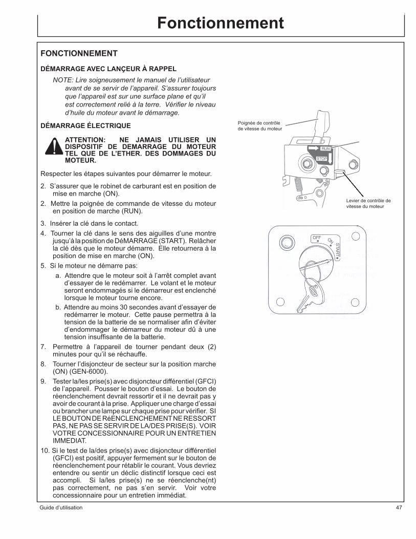
Guide d’utilisation 47
FONCTIONNEMENT
DÉMARRAGE AVEC LANÇEUR À RAPPELNOTE: Lire soigneusement le manuel de l’utilisateur
avant de se servir de l’appareil. S’assurer toujours que l’appareil est sur une surface plane et qu’il est correctement relié à la terre. Vérifier le niveau d’huile du moteur avant le démarrage.
DÉMARRAGE ÉLECTRIQUE
ATTENTION: NE JAMAIS UTILISER UN DISPOSITIF DE DEMARRAGE DU MOTEUR TEL QUE DE L’ETHER. DES DOMMAGES DU MOTEUR.
Respecter les étapes suivantes pour démarrer le moteur.
2. S’assurer que le robinet de carburant est en position de mise en marche (ON).
2. Mettre la poignée de commande de vitesse du moteur en position de marche (RUN).
3. Insérer la clé dans le contact.4. Tourner la clé dans le sens des aiguilles d’une montre
jusqu’à la position de DéMARRAGE (START). Relâcher la clé dès que le moteur démarre. Elle retournera à la position de mise en marche (ON).
5. Si le moteur ne démarre pas:a. Attendre que le moteur soit à l’arrêt complet avant
d’essayer de le redémarrer. Le volant et le moteur seront endommagés si le démarreur est enclenché lorsque le moteur tourne encore.
b. Attendre au moins 30 secondes avant d’essayer de redémarrer le moteur. Cette pause permettra à la tension de la batterie de se normaliser afin d’éviter d’endommager le démarreur du moteur dû à une tension insuffisante de la batterie.
7. Permettre à l’appareil de tourner pendant deux (2) minutes pour qu’il se réchauffe.
8. Tourner l’disjoncteur de secteur sur la position marche (ON) (GEN-6000).
9. Tester la/les prise(s) avec disjoncteur différentiel (GFCI) de l’appareil. Pousser le bouton d’essai. Le bouton de réenclenchement devrait ressortir et il ne devrait pas y avoir de courant à la prise. Appliquer une charge d’essai ou brancher une lampe sur chaque prise pour vérifier. SI LE BOUTON DE RéENCLENCHEMENT NE RESSORT PAS, NE PAS SE SERVIR DE LA/DES PRISE(S). VOIR VOTRE CONCESSIONNAIRE POUR UN ENTRETIEN IMMEDIAT.
10. Si le test de la/des prise(s) avec disjoncteur différentiel (GFCI) est positif, appuyer fermement sur le bouton de réenclenchement pour rétablir le courant. Vous devriez entendre ou sentir un déclic distinctif lorsque ceci est accompli. Si la/les prise(s) ne se réenclenche(nt) pas correctement, ne pas s’en servir. Voir votre concessionnaire pour un entretien immédiat.
Fonctionnement
Poignée de contrôle de vitesse du moteur
Levier de contrôle de vitesse du moteur

48 Guide d’utilisation
Utilisation du groupe électrogène
ARRÊTATTENTION : POUR UNE DURÉE DE VIE UTILE MAXIMALE DU MOTEUR, YANMAR RECOMMANDE DE LAISSER LE MOTEUR TOURNER AU RALENTI, SANS CHARGE, PENDANT 5 MINUTES AVANT SON ARRÊT. CECI PERMETTRA AUX COMPOSANTS DU MOTEUR QUI FONCTIONNENT À DE HAUTES TEMPÉRATURES, TELS QUE LE TURBO COMPRESSEUR (SI INCLU) ET LE SYSTÈME D’ÉCHAPPEMENT, DE REFROIDIR UN PEU AVANT QUE LE MOTEUR SOIT MIS À L’ARRÊT.
Placer la commande de vitesse du moteur en position d’arrêt (STOP).
ATTENTION: SI LE MOTEUR CONTINUE DE TOURNER APRÈS AVOIR PLACÉ LA COMMANDE DE VITESSE DU MOTEUR EN POSITION D’ARRÊT (STOP), TOURNER LE ROBINET DE CARBURANT À LA POSITION FERMÉE.
1. Appuyer sur le levier d’arrêt (STOP) et la poignée de contrôle de vitesse du moteur retournera automatiquement a la position d’arrêt (STOP).Note: La poignée de contrôle de vitesse est à res-
sort, donc, lorsque vous poussez sur le levier d’arrêt (STOP), la poignée de contrôle de vitesse retourne à la position d’arrêt. Il n’y a pas de posi-tion de ralenti ou de vitesses intermédiaires.
MODÈLES À DÉMARRAGE ÉLECTRIQUETourner la clé jusqu’à la position d’arrêt (OFF) et retirer-la du contact.APRÈS L’ARRÊT DU MOTEUR1. Déplacer le levier du robinet de carburant jusqu’à la
position fermée.2. Tirer lentement sur la poignée du lanceur à rappel jusqu’au
point de résistance (le point dans la course de compression où les soupapes d’admission et d’échappement sont fermées). Ceci aide à éviter la formation de rouille lorsque le moteur ne fonctionne pas.
3. Si le moteur ne va pas être utilisé pendant 6 mois ou plus, consulter les instructions supplémentaires sur le remisage.
COMMANDESPANNEAU DE COMMANDE:Les groupe électrogènes sont équipés comme suit:
- Compteur horaire - Voltmètre - Disjoncteurs- Deux prises femelles doubles (2 prises) protégées
par disjoncteur différentiel (GFCI) de 125 Volt, 20 Ampères.
- Une prise verrouillable de 125 Volt, 30 Ampères.- Une prise verrouillable de 125/250 Volt, 20 Am-
pères NOTE: Les prises verrouillables de 125 Volt, 20
Ampères et de 125/250 Volt, 30 Ampères ne sont

Operator’s Manual 49
Utilisation du groupe électrogène
PAS protégées par un disjoncteur différentiel. Il faut utiliser des disjoncteurs différentiels externes si un tel dispositif est nécessaire ou désiré. Con-sulter les consignes de la section “Disjoncteur Différentiel” pour plus d’information.
AVERTISSEMENT: IL NE FAUT JAMAIS DÉPASSER LA CAPACITÉ NOMINALE DUNE PRISE. CES PRISES SONT PROTÉGÉES CONTRE LES SURCHARGES PAR DES DISJONCTEURS MAGNÉTIQUES À RÉEN CLENCHEMENT. SI UN DISJONCTEUR SE DÉCLENCHE, IL FAUT EN DÉTERMINER LA CAUSE ET LA CORRIGER AVANT DE CONTINUER L’UTILISATION.
COMMANDESCOMPTEUR HORAIRE:
Ces groupes électrogènes sont équipés d’un compteur horaire qui enregistre le nombre d’heures de fonctionnement de l’appareil. Ceci est très utile pour programmer l’entretien. Consulter le tableau périodique d’entretien pour le programme d’entretien recommandé.
VOLTMÉTRE:Ces groupes électrogènes sont équipés d’un voltmètre. Le voltmètre est utilisé pour contrôler la tension correcte de l’appareil.
MAIN BREAKER:Ces générateurs sont équipés d’un disjoncteur principal qui protège jusque dedans à une surcharge. Ce disjonc-teur principal doit être “ON” pour que n’importe quelle puissance soit tirée à partir de l’unité.TAILLE DE CÂBLE:Une tension insuffisante risque d’endommager l’équipement. Par conséquent, pour éviter les chutes de tension excessives entre le groupe électrogène et l’équipement, le câble utilisé devra être de calibre suf-fisant par rapport à sa longueur. Le tableau de sélection des câbles indique la longueur maximale des câbles en fonction du calibre permettant d’acheminer les charges indiquées en toute sécurité.CHARGES DES MOTEURS ÉLECTRIQUES:Il est caractéristique pour les moteurs électriques ordi-naires en fonctionnement normal de consommer jusqu’à six fois leur courant de fonctionnement au démarrage. Ce tableau peut être utilisé pour estimer la puissance en Watts nécessaire pour démarrer les moteurs électriques “CODE G.”
ATTENTION: SI UN MOTEUR ÉLECTRIQUE REFUSE DEDÉMARRER OU D’ATTEINDRE SON RÉGIME DE FONCTIONNEMENT, ARRÊTER IMMÉDIATEMENT L’APPAREIL OU L’OUTIL AFIN D’ÉVITER TOUT DOMMAGE À L’ÉQUIPEMENT. VÉRIFIER TOUJOURS QUE LA CONSOMMATION DE L’OUTIL OU DE L’APPAREIL UTILISÉ EST COMPATIBLE AVEC LA PUISSANCE DE SORTIE DU GROUPE ÉLECTROGÈNE.

50 Operator’s Manual
Utilisation du groupe électrogène
COURANT EN CHARGE EN WATTS LONGUEUR MAXIMALE DE CÂBLE (pi.)
AMPÈRES SOUS 120V SOUS 240V FIL N°8 FIL N°10 FIL N°12 FIL N°14 FIL N°16
2,5 300 600 1000 600 375 250
5 600 1200 500 300 200 125
7,5 900 1800 350 200 125 100
10 1200 2400 250 150 100 50
15 1800 3600 150 100 65
20 2400 4800 175 125 75 50
25 3000 6000 150 100 60
30 3600 7200 125 65
40 4800 9600 90
PUISSANCE DU PUISSANCE (W) DE PUISSANCE (WATTS) NÉCESSAIRE AU DÉMARRAGE DU MOTEUR
MOTEUR (CH) FONCTIONNEMENT RÉPULSION-INDUCTION CONDENSATEUR PHASE AUXILIAIRE
1/8 275 600 850 1200
1/6 275 600 850 2050
1/4 400 850 1050 2400
1/3 450 975 1350 2700
1/2 600 1300 1800 3600
3/4 850 1900 2600
1 1100 2500 3300

Guide d’utilisation 51
SYMPTÔME PROBLÈME SOLUTION
Le moteur ne démarre pas. L’interrupteur du moteur est Mettre l’interrupteur du moteur en en position d’arrêt (OFF). position de marche (ON). Le réservoir de carburant est vide. Remplir le réservoir selon les instructions contenues dans ce manuel. La soupape de carburant est fermée. Ouvrir la soupape de carburant.
Pas de courant en sortie du Déclenchement des disjoncteurs. Réarmer les disjoncteurs. groupe électrogène. Cordons électriques et rallonges Vérifier la capabilité des cordons inadéquats. électriques et des rallonges dans la section Commandes; la taille des câbles dans ce manuel. Consulter un concessionnaire Mi-TM.
Dépannage

52 Guide d’utilisation
ENTRETIEN DU GROUPE ÉLECTROGÈNEMaintenir tous les évents dégagés.Maintenir le groupe électrogène dans un état propre. NE PAS l’asperger d’eau.Périodiquement, vérifier et serrer tous les éléments de fixation (écrous et boulons), voir le tableau d’entretien péri-odique.
FICHIER D’ESSAIS DES DISJONCTEURS:Comme avec les autres dispositifs de sécurité, les disjoncteurs (GFCI) fournis avec ces groupes électrogènes doivent être examinés chaque mois pour assurer qu’il fonctionne correctement. Pour tester les disjoncteurs (GFCI), suivre les instructions suivantes et enregistrer la date du test ci-dessous.
1. Appuyer sur le bouton “TEST” avec le groupe électrogène en marche. Le bouton de réenclenchement (RESET) devrait sortir. Les deux prises du boîtier doivent alors être hors tension. Vérifier en branchant une lampe dans chaque prise.
AVERTISSEMENT: SI LE BOUTON DE RÉENCLENCHEMENT NE RESSORT PAS, NE PAS SE SERVIR DE LA/DES PRISE(S). VOIR VOTRE CONCESSIONNAIRE JOHN DEERE POUR UN ENTRETIEN IMMEDIAT.
2. Si le disjoncteur (GFCI) fonctionne normalement, remettre le système sous tension en appuyant FERMEMENT sur le bouton de réenclenchement “RESET” jusqu’à ce qu’un déclic distinctif soit entendu ou senti. SI IL N’EST PAS POSSIBLE DE RéARMER LE DISJONCTEUR DIFFERENTIEL (GFCI), N’UTILISER AUCUNE DES PRISES DU BOITIER DOUBLE. Il faut faire réparer l’appareil immédiatement par un centre de service agréé John Deere.
3. Des charges générées par des vibrations élevées ou des chocs mécaniques violents peuvent déclencher les disjoncteurs différentiels (GFCI). Si l’un ou l’autre des disjoncteurs différentiels se déclenche tout seul, le réarmer et exécuter les étapes du test 1 et 2.
4. Répéter les étapes 1 à 3 pour le second disjoncteur différentiel (GFCI).
AVERTISSEMENT: BIEN QUE LA PROCÉDURE CI-DESSUS INDIQUE QUE LE DISJONCTEUR DIFFÉRENTIEL (GFCI) FONCTIONNE CORRECTEMENT AVEC UN GROUPE ÉLECTROGÈNE QUI N’EST PAS MIS À LA TERRE OU QUI EST MAL MIS À LA TERRE, IL FAUT CEPENDANT METTRE LE
Entretien
NOTE: Dans certains cas, le disjoncteur différentiel ne fournit pas de protection contre les risques d’électrocutions. EXEMPLE: Une personne peut recevoir un choc si elle touche deux ou plus des fils d’un cordon électrique endommagé et n’est pas en contact direct avec la terre. Puisque le courant parasite n’a pas de passage vers la terre, le disjoncteur différentiel ne peut pas remplir son rôle et la personne peut recevoir des blessures graves.
Le disjoncteur différentiel est simplement une caractéristique de sécurité supplémentaire. Rien ne peut remplacer le respect des précautions de sécurité, des bonnes pratiques de sécurité avec les circuits électriques et un bon entretien des cordons électriques, de l’équipement et des connexions.
Année Janv. Févr. Mars Avr. Mai Juín. Juill. Aoüt. Sep. Oct. Nov. Déc.

Guide d’utilisation 53
Entretien
GROUPE ÉLECTROGÈNE À LA TERRE EN SUIVANT LES INSTRUCTIONS DE MISE À LA TERRE À POUR QUE LE DISJONCTEUR DIF FÉRENTIEL (GFCI) SOIT EFFICACE ET PROTÈGE L’UTILISATEUR CONTRE LES COURANTS PARASITES.
MOTEUR:Le moteur de ce groupe électrogène est régulé pour fonc-tionner à des vitesses proches de 3600 tours/mn (60Hz) sur toute la plage de puissance fournie. La vitesse de marche à vide (avant qu’une charge soit appliquée) sera juste un peu plus haute que la vitesse de charge et est normalement réglé à 3750 tours/mn.
AVERTISSEMENT: IL NE FAUT PAS MODIFIER LE MÉCANISME DU RÉGULATEUR, CHANGER SON RÉGLAGE DE FAÇON EXPÉRIMENTALE, NI POUSSER L’ACCÉLÉRATEUR POUR ESSAYER DE PRODUIRE PLUS DE COURANT ÉLECTRIQUE; CECI RISQUE D’ENDOMMAGER L’ÉQUIPEMENT ET DE CAUSER DES BLESSURES. LE RÉGLAGE DU RÉGIME DU RÉGULATEUR DOIT ÊTRE LAISSÉ AUX BONS SOINS D’UN CONCESSIONNAIRE JOHN DEERE.
VIDANGE D’HUILE:Changer l’huile après les premières 50 heures de service. Par la suite, il faut la changer toutes les 200 heures.Vidanger comme suit:
1. S’assurer que le moteur est sur une surface plane.2. Démarrer le moteur et l’amener à sa température de
fonctionnement.3. Mettre le moteur à l’arrêt.4 . Retirer le bouchon jauge à huile pour permettre à l’huile
pour moteur de se vider plus facilement.5. Placer un récipient sous le moteur pour recueillir l’huile
usée.6. Retirer le bouchon de vidange qui se trouve en dessous
du bloc-cylindres. Permettre à l’huile de se vider.7. Une fois l’huile entièrement vidée du moteur, remettre
le bouchon de vidange et serrer jusqu’à 14-17 pieds par livres.
8. Se débarrasser correctement de l’huile usée.
POUR REMPLIR AVEC DE L’HUILE:1. S’assurer que le moteur est sur une surface plane.2. Retirer le bouchon jauge à huile.3. Ajouter la quantité d’huile pour moteur indiquée dans
l’un ou l’autre orifice de remplissage d’huile.4. Attendre une minute et vérifier le niveau d’huile.5. Ajouter plus d’huile si nécessaire.6. Réinsérer complètement le bouchon jauge à huile et
serrer à la main. Le fait de trop serrer le bouchon jauge à huile l’endommagera.
Bouchon jauge à huile
Orifices de remplissage d'huile

54 Guide d’utilisation
Ecrou à oreille Ecrou à oreille
CouvercleElément de filtre à air
Fourreau en mousse
AVERTISSEMENT: L’HUILE QUI S’ÉCOULE PEUT ÊTRE TRÈS CHAUDE. POUR RÉDUIRE LES RISQUES DE BRÛLURES, LA MANIPULER AVEC PRÉCAUTION. METTRE L’HUILE USÉE AU REBUT D’UNE FAÇON APPROPRIÉE.
FILTRE À AIR:AVERTISSEMENT : RISQUE D’INCENDIE OU D’EXPLOSION. NE PAS UTILISER D’ESSENCE OU DE SOLVANTS AVEC UN POINT D’ÉCLAIR BAS POUR NETTOYER L’ÉLÉMENT. NETTOYER L’ÉLÉMENT DANS UN ENDROIT BIEN VENTILÉ. S’ASSURER QU’IL N’Y A AUCUNE ÉTINCELLES OU FLAMMES PRÈS DE LA ZONE DE TRAVAIL: CECI INCLUT TOUT APPAREIL MÉNAGER AVEC UNE VEILLEUSE.ATTENTION: IL NE FAUT JAMAIS FAIRE FONCTIONNER LE MOTEUR SANS FILTRE À AIR, SOUS PEINE DE DOMMAGES SÉRIEUX.
Un élément de filtre à air encrassé de poussière a un ef-fet négatif sur le bon fonctionnement du moteur. Ne pas oublier de nettoyer l’élément de filtre à air périodiquement.1. Retirer l’écrou à oreille.2. Retirer le couvercle de filtre à air.3. Retirer l’écrou à oreille.4. Retirer l’élément de filtre à air et l’élément fourreau en
mousse extérieur.5. Envoyer de l’air à travers les deux éléments en utilisant
42-71 psi d’air comprimé pour retirer les particules. Utiliser la pression d’air la plus basse possible pour retirer la poussière sans endommager les éléments.
6. Si l’un ou l’autre des éléments est endommagé, les remplacer tous les deux (ils ne sont pas vendus individuellement).
7. Nettoyer l’intérieur du couvercle de filtre à air.8. Installer l’élément de filtre à air dans le boîtier du filtre
à air.9. Faire glisser l’élément fourreau en mousse extérieur
par-dessus l’élément du filtre à air.10. Installer l’écrou à oreille et serrer à la main. Le fait de
trop serrer l’écrou à oreille endommagera l’ensemble du filtre à air
11. Installer le couvercle du filtre à air.12. Installer l’écrou à oreille et serrer à la main. Le fait de
trop serrer l’écrou à oreille endommagera l’ensemble du filtre à air.
TABLEAU D’ENTRETIEN PÉRIODIQUE:Le moteur a besoin d’un entretien normal à des intervalles réguliers afin d’assurer son bon fonctionnement pendant une longue période de temps. Le Tableau d’Entretien Périodique ci-dessous identifie les inspections et interven-tions d’entretien périodiques ainsi que leurs intervalles appropriés. Le point centré indique que l’intervention cor-respondante doit être faite à cet intervalle.
NOTE: Certains réglages nécessitent l’utilisation d’outils spéciaux ou d’autre équipement. Un tachymètre électronique aidera à régler le régime de ralenti et de service.
Entretien

Guide d’utilisation 55
Entretien
* Exécuter ces opérations après les 50 premières heures de service, ensuite aux intervalles recommandés. ** Intervention plus fréquente en cas d’environnement poussiéreux.
NOTE: Ces interventions doivent être effectuées avec des outils appropriés. Consulter votre centre de service John Deere pour l’entretien si vous n’avez pas le bon équipement et les compétences mécaniques.
Chaque Toutes les Toutes les Toutes les Avant jour 25h 100 h 200 h remisage
Vérifier le niveau de carburant •
Vérifier le niveau d’huile du moteur •
Vérifier qu’il n’y a pas d’écrous ou de boulons desserrés ou perdus •
Rechercher d’éventuelles fuites •
Vérifier que les ailettes du cylindre et de la culasse ne sont pas sales ou poussiéreuses. •
Niveau de l’electrolyte de la batterie •
Inspection de la conduite de carburant (remplacer selon le besoin) •
Nettoyer l’élément en mousse du filtre à air (**) •
Serrer les écrous et boulons (*) •
Vidange d’huile du moteur (*) •
Nettoyer le filtre à carburant •
Remplacer la cartouche filtrante en papier (**) •
Nettoyer la poussière et saleté des ailettes du cylindre et de la culasse (**) •
Nettoyer la bougie et régler l’écartement des électrodes •
Ajouter du stabilisateur de carburant •
Faire tourner le moteur jusqu’a sec de carburant •
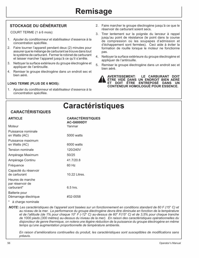
Service
56 Operator’s Manual
STOCKAGE DU GÉNÉRATEURCOURT TERME (1 à 6 mois):
1. Ajouter du conditionneur et stabilisateur d’essence à la concentration spécifiée.
2. Faire tourner l’appareil pendant deux (2) minutes pour assurer que le mélange de carburant se trouve dans tout le système de carburant. Fermer le robinet de carburant et laisser marcher l’appareil jusqu’à ce qu’il s’arrête.
3. Nettoyer la surface extérieure du groupe électrogène et appliquer de l’antirouille.
4. Remiser le groupe électrogéne dans un endroit sec et bien aéré.
LONG TERME (PLUS DE 6 MOIS):
1. Ajouter du conditionneur et stabilisateur d’essence à la concentration spécifiée.
Remisage2. Faire marcher le groupe électrogéne jusqu’à ce que le
réservoir de carburant soient secs.3. Tirer lentement sur la poignée du lanceur à rappel
jusqu’au point de résistance (le point dans la course de compression où les soupapes d’admission et d’échappement sont fermées). Ceci aide à éviter la formation de rouille lorsque le moteur ne fonctionne pas.
4. Nettoyer la surface extérieure du groupe électrogène et appliquer de l’antirouille.
5. Remiser le groupe électrogéne dans un endroit sec et bien aéré.
AVERTISSEMENT: LE CARBURANT DOIT ÊTRE VIDÉ DANS UN ENDROIT BIEN AÉRÉ ET DOIT ÊTRE ENTREPOSÉ DANS UN CONTENEUR HOMOLOGUÉ POUR ESSENCE.
CARACTÉRISTIQUESARTICLE CARACTÉRISTIQUES AC-G6000DY Moteur Yanmar Puissance nominale en Watts (AC) 5000 watts Puissance maximum en Watts (AC) 6000 watts Tension nominale 120/240V Ampérage Maximum 50/25Ampérage Continu 41.7/20.8 Fréquence 60 HzCapacité du réservoir de carburant 10.22 Litres. Heures de marche par réservoir de carburant* 6.5 hrs. Batterie pour Démarrage électrique #32-0058 * à charge nominale
NOTE: Les caractéristiques de l’appareil sont basées sur un fonctionnement en conditions standard de 60 F (15° C) et au niveau de la mer. La performance du groupe électrogène devra être diminuée en fonction de la température et de l’altitude (de 1% pour chaque 10° F (-12° C) au-dessus de 60° F(15° C) et de 3,5% pour chaque tranche de 1000 pieds (300 mètres) au-dessus du niveau de la mer). En raison des caractéristiques opérationnelles du disjoncteur de genre thermique, on notera une légère réduction de la puissance du groupe électrogène en même temps qu’une augmentation proportionnelle de température ambiente.
En raison d’améliorations continuelles du produit, les caractéristiques sont susceptibles de modifications sans préavis.
Caractéristiques

Guide d’utilisation 57
Accessories
KIT DE POIGNÉES ET ROUES: AW-5740-0011Facilite la portabilité du groupe électrogène. Le Kit de Poi-gnées et Roues inclut les roues, les poignées, les pièces de montage et les instructions nécessaires pour assembler le kit au groupe électrogène.
KIT DE BARRE DE LEVAGE: AW-5090-0007Est utilisé pour soulever le groupe électrogène en toute sécurité. Le kit de barre de levage inclut la barre de levage, les pièces de montage et les instructions nécessaires pour assembler le kit au groupe électrogène.
NOTER LE NUMÉRO DE SÉRIENoter ci-dessous le numéro de modèle ainsi que le numéro de série et la date d’achat de votre appareil. Votre concessionnaire a besoin de ces renseignements lors des commandes de pièces
Numéro de modèle ________________________________________
Numéro de série __________________________________________
Date d’achat _____________________________________________ (À remplir par l’acheteur)

58 Guide d’utilisation
Garantie
CONDITIONS DE LA GARANTIE
John Deere garantit toutes les pièces (à l’exception de celles stipulées ci-dessous), de votre nouveau groupe électrogène en cas de défauts de matériaux et de fabrication pendant les périodes suivantes:
Pendant deux (2) années à partir de la date d’achat initiale.
Les pièces défectueuses ne résultant pas d’une usure normale seront réparées ou remplacées à notre choix pendant la période de garantie. Quoi qu’il arrive, le remboursement est limité au prix d’achat.
PIECES EXCLUES DE LA GARANTIE
1. Le moteur et le générateur sont garanti séparément par son fabricant et est sujet aux limites ci-inclus.
2. Cette garantie ne couvre pas les pièces endommagées par l’usure normale, une mauvaise utilisation, une utilisation abusive ou un fonctionnement autre que recommandé. La garantie ne couvre pas les dégâts provoqués par un mauvais suivi des procédures de fonctionnement et d’entretien .
3. L’utilisation de pièces de réparation autres que celles d’origine annule la garantie.4. Les pièces renvoyées en port payé, à notre usine ou à un centre de réparation John
Deere agréé seront inspectées et remplacées gratuitement si elles s’avérent être défectueuses et couvertes par la garantie. Il n’existe aucune garantie prolongeant les dates d’expiration stipulées ci-dessus. Le fabricant n’est en aucun cas responsable des pertes d’usage, de temps ou de location, des dérangements causés, des pertes commerciales ou des dommages qui en résultent.
Pour toute question de service ou de garantie, s’adresser àMi-T-M Corporation, 8650 Enterprise Drive, Peosta, IA 52068-0050
Tél.: JD-KLEEN (1-877-535-5336) Fax 563-556-1235Du lundi au vendredi de 8h00 à 17h00, heure centrale

Operator’s Manual 59
DÉCLARATION DE GARANTIE CONTRÔLE D’ÉMISSIONS POUR LA CALIFORNIEVOS DROITS ET OBLIGATIONS DE GARANTIE
Le comité des ressources de l’air de la Californie et John Deere sont heureux d’expliquer la garantie du système de contrôle d’émissions de votre petit moteur non routier (désigné ci-dessous par “SORE”). En Californie, les nouveaux SOREs doivent être conçus, construits et équipés pour se conformer aux normes anti-smog rigoureuses de l’état.
John Deere doit garantir le système de contrôle d’émissions de vos SOREs pendant la durée de temps décrite ci-dessous, à condition qu’il n’y ait eu aucun abus, négligence ou entretien incorrect de vos SOREs.
Votre système de contrôle d’émissions peut inclure des pièces telles que le carburateur ou le système d’injection de carburant, les canalisations de carburant et le circuit d’allumage. Les tuyaux, attaches, connecteurs et autres pièces liés aux émissions peuvent aussi être inclus.
Quand une condition couverte par la garantie existe, John Deere réparera gratuitement votre petit moteur non-routier, y compris le diagnostic, les pièces et la main d’œuvre.
COUVERTURE DE LA GARANTIE DU FABRICANT :Le système de contrôle d’émissions est garanti pendant deux années. Si toute pièce liée aux émissions de votre moteur est défectueuse, elle sera réparée ou remplacée par John Deere.
RESPONSABILITÉS DU PROPRIÉTAIRE VIS À VIS DE LA GARANTIE:
- En tant que propriétaire du SORE, vous êtes responsable de l’exécution des opérations d’entretien obligatoires énumérées dans le manuel du propriétaire. John Deere recommande que vous conserviez tous les reçus concernant l’entretien de votre SORE, mais John Deere ne peut dénier la garantie seulement à cause de reçus manquants.
- En tant que propriétaire du SORE, vous devez cependant être conscient que John Deere peut refuser la couverture de la garantie si votre SORE ou une pièce tombe en panne à cause d’abus, de négligence, d’entretien incorrect ou de modifications non approuvées.
- Vous êtes responsable de la présentation de votre SORE à un centre de distribution ou chez un concessionnaire réparateur agréé par John Deere Corporation, 8650 Enterprise Drive, Peosta, IA 52068 (désigné ci-dessous par John Deere) dès qu’un problème est identifié. Les réparations de garantie doivent être effectuées dans un délai raisonnable sans dépasser 30 jours.
Pour toute question relative à votre couverture de garantie, vous devez contacter le département Service après-vente de John Deere à 1-800-553-9053.
COUVERTURE DE GARANTIE GÉNÉRALE DES SYSTÈMES D’ÉMISSIONS-La Californie Seulement-
John Deere garantit à l’acheteur initial et à chaque acheteur suivant que le SORE (1) a été conçu, fabriqué et équipé pour se conformer à tous les règlements en vigueur, et (2) est exempt de défauts de matière première ou de construction qui feraient qu’il ne soit pas conforme aux normes comme peut être applicable dans les termes et conditions indiquées ci-dessous.
(a) La période de garantie commence à la date où le moteur est livré à l’acheteur initial ou lors de sa première utilisation. La période de garantie est de deux années.
(b) La garantie des pièces relatives aux émissions, sujette à certaines conditions et exclusions telles qu’indiquées ci-dessous, est la suivante :
(1) Toute pièce sous garantie qui ne doit pas être remplacée au titre d’une révision obligatoire spécifiée dans votre manuel du propriétaire est garantie pour la période de garantie indiquée ci-dessus. Si la pièce s’avère défectueuse pendant la période de couverture de garantie, elle sera réparée ou remplacée par John Deere selon le paragraphe (4) ci-dessous. Toute pièce ainsi réparée ou remplacée au titre de la garantie sera garantie pendant le reste de la période de garantie.
Garantie

60 Operator’s Manual
(2) Toute pièce sous garantie qui est seulement programmée pour une inspection régulière dans votre manuel du propriétaire est garantie pour la période de garantie indiquée ci-dessus. Toute pièce ainsi réparée ou remplacée au titre de la garantie sera garantie pendant le reste de la période de garantie.
(3) Toute pièce sous garantie qui doit être remplacée au titre d’une révision obligatoire dans votre manuel du propriétaire n’est garantie que pendant la période de temps jusqu’à la première date de remplacement programmé pour cette pièce. La pièce sera réparée ou remplacée par John Deere selon le paragraphe (4) ci-dessous si elle s’avére défectueuse avant le premier remplacement programmé. Toute pièce ainsi réparée ou remplacée au titre de la garantie sera garantie pendant le reste de la période jusqu’au moment du premier remplacement programmé pour la pièce.
(4) La réparation ou le remplacement de toute pièce sous garantie, sous réserve des conditions ci-incluses, sera exécuté gratuitement chez un concessionnaire réparateur agréé.
(5) Nonobstant les clauses de ce document, les services ou réparations sous garantie seront fournis par tous nos centres de distribution agréés pour l’entretien des moteurs en question.
(6) Le propriétaire ne sera pas facturé pour le travail de diagnostic qui mène à la détermination qu’une pièce sous garantie est en effet défectueuse, à condition que le travail de diagnostic soit effectué par un concessionnaire réparateur agréé.
(7) John Deere est responsable pour les dommages aux autres composants du moteur se situant autour de la zone de la panne résultant de la défaillance de toute pièce sous garantie.
(8) Pendant toute la période de garantie du moteur indiquée ci-dessus, John Deere maintiendra à disposition un stock de pièces sous garantie suffisant pour satisfaire la demande prévue pour telles pièces.
(9) Toute pièce de remplacement peut être utilisée pour l’exécution de tout entretien ou réparations au titre de la garantie et doit être fournie gratuitement au propriétaire. Une telle utilisation ne changera pas les obligations de John Deere vis à vis de la garantie.
(10) Les pièces ajoutées ou modifiées qui ne sont pas homologuées par le comité des ressources de l’air de la Californie ne doivent pas être utilisées. L’utilisation de pièces ajoutées ou modifiées non-homologuées par l’acheteur initial constituera un motif de non-application de garantie. John Deere ne pourra être tenu responsable de la défaillance de pièces sous garantie dont la cause est l’utilisation de pièces ajoutées ou modifiées non-homologuées.
(c) PIÈCES SOUS GARANTIE:
La réparation ou le remplacement au titre de la garantie de toute pièce normalement couverte par cette garantie peut être refusée si John Deere démontre que le moteur a été abusé, négligé ou mal entretenu, et que cet abus, négligence ou mauvais entretien est la cause directe de la nécessité de réparer ou remplacer cette pièce. Néanmoins, le réglage d’une pièce comprenant un dispositif limiteur de réglage installé en usine et qui fonctionne correctement est tout de même couvert par la garantie. Les pièces suivantes sont couvertes sous la garantie d’émissions.
1. Système de dosage de Carburant (A) Carburateur et pièces internes (et/ou régulateur de pression ou système d’injection de carburant). (B) Système de rétroaction et de commande de rapport d’air/carburant, si applicable. (C) Système d’enrichissement au démarrage à froid, si applicable. (D) Assemblage régulateur (carburant essence, si applicable). 2. Système d’admission d’air (A) Collecteur d’admission, si applicable. (B) Filtre à air. 3. Circuit d’allumage (A) Bougies d’allumage. (B) Magnéto ou circuit d’allumage électronique. (C) Système d’avance/retard à l’allumage, si applicable. 4. Tubulure d’échappement, si applicable. 5. Système d’évaporation. (A) Canalisation de carburant. (B) Raccords de canalisation de carburant.
Garantie

Operator’s Manual 61

62 ManualdelOperador
IntroducciónGraciasparacomprandoesteJohnDeereproducto.Leaestemanualconcuidadoparaaprendercomooperaryheacerieservicaosumáquinacorrecto.Fallaresultaríaenlesionespersonalesodañoaequipo.Estemanualdebeconsiderarunapartepermanentedesumáquinaydebequedarconmáquinacuandovenderla.MedidasenestemanualsedanensistemamétricoyenequivalentesdeunidadesdeEstadoUnidos.Usesólopartesycierresdereemplazarcorrectos.Cierresmétricosypulgadasnecesitarianuntirónespecialdemétricoopulgada.Ladosdemanoderechaymanoizquierdasedeterminandequedaalfindemáquina.
Elnúmerodeserieestásituadaenseccióndeespecifi-cacionesonúmerosdeidentificación.Escribacorrectatodosnúmerosparaayndaríaenencontrarlamáquinasisearobado.Suconcesionariotambiénnecesiteestosnúmeroscuandoordenaríapartes.Ponganúmerosdeidentificaciónenlugarseguroatuerademáquina.GarantíaprovecedeconcesionarioJohnDeereparaquienopereymantengasuequipocomodescribidoenestemanual.Estemanualestáexplicadoencertificadodegarantíaqueseveaenestemanual.EstagarantíaprovecelaseguridadquesuconcesionarioJohnDeeredaríagarantiadeproductosdondedefectosaparecendurantetiempodegarantia.Debeabusaralequipoocambiosparamodificarlafunciónatrásdeespe-cificacionesdefabricalagarantiaserávació.
ADVERTENCIA: Este producto tiene plomo, una sustancia química conocida al Estado de California a causar cáncer y defectos de nacimiento u otro daño reproductivo.Lávese las manos despues de usar este producto.
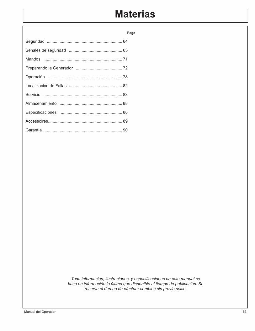
ManualdelOperador 63
Materias Page
Seguridad................................................................. 64
Señalesdeseguridad.............................................. 65
Mandos................................................................... 71
PreparandolaGenerador........................................ 72
Operación................................................................ 78
LocalizacióndeFallas.............................................. 82
Servicio.................................................................... 83
Almacenamiento...................................................... 88
Especificaciónes..................................................... 88
Accessoires................................................................ 89
Garantía.................................................................... 90
Toda información, ilustraciónes, y especificaciones en este manual se basa en información lo último que disponible al tiempo de publicación. Se
reserva el dercho de efectuar combios sin previo aviso.

64 ManualdelOperador
WARNING
WARNINGS IN
THE MANUALS.
WARNINGS IN
THE MANUALS.
CAUTION
O CAUTIONS IN
O THE MANUALS
O CAUTIONS IN
O THE MANUALS
O CAUTIONS IN
O THE MANUALS
O CAUTIONS IN
O THE MANUALS
SeguridadRECONOZCAINFORMACIÓNDESEGURIDADEsteeselsímbolodealertadeseguridad.Cuandomireestesímboloenlamáquinaomanual,seaalertadeposibi-lidadopotenciadegravespersonales.Sigaprecaucionesrecomendablesyprácticasdeoper-ación.
COMPRENDAPALABRASDEALERTASUnapalabradealerta--Peligro,Advertencia,Precaución--seusaconelsímbolodealertadeseguridad.Peligroindicalasituaciónmásseria.SeñalesdeseguridadcomoPELIGROyADVERTENCIAestásituadacercaderiesgosespecíficos.Precaucionesgeneralesestánenunalistaenlasseñalesdeseguridadprecauciónamensajesdeseguridadenestemanual.
SIGALASINSTRUCCIÓNESDESEGURIDADLeaconciudadotodosmensajesdeseguridadenestemanualyenlasseñalesdeseguridadenmáquina.Man-tengaseseñalesdeseguridadencondiciónbueno.Reem-placedesaparecidososeñalesdeseguridadcondaño.Aseguresequecomponentesnuevosdeequipoypartesdereparaciónincluirlasseñalesdeseguridadúltimo.Señalesdeseguridadparareemplacesondisponiblesdesuconc-esario.Aprendacomooperarlamáquinaycomousarlosmandoscorrecta.Nopermitanadieparaoperarsininstrucciones.Mantengaselamáquinaencondicióncorectaparatrabajar.Modificaciónesconnoautorizadoalamáquinapuedenafectarlafuncióny/oseguridadyafectalavidademá-quina.Siustednoentiendecualquierpartedeestemanualynonecesitaayuda,entreencontactoconasudistribuidor.

ManualdelOperador 65
MONÓXIDODECARBONO-GASVENENOSOUsegeneradorenairelibre,afueradeventanasabiertas,tiros,opuer-tas.Exhaustodegeneradorcontienemonóxidodecarbono-ungasvene-nosoquepuedematarle.Nopuedeoleroverestegas.Nuncausegeneradorenespacioscerradosoparcialamentecerrados.Generadorespuedeproducirnevelesaltasdemonóxidodecarbonomuyrápido.Cuandouseungeneradorportable,recuerdequenopuedeolerovermonóxidodecarbono.Aunquesinopuedaolergasesdeexhaus-to,puedeexponerleamonóxidodecarbono.Siempiezasentirenfermo,mareo,odébilcuandousandogenerador,vayaadentroPRONTO.NORETRASE.Monóxidodecarbonodegen-erardorespuedellevarrápidamenteatodoincapacitadoymuerte.Sitengasíntomasserias,tengaatenciónmedicaimmediamente.Digaempleadosmedicosquesospechardevenenosodemonóxidodecar-bono.Sitengasíntomasmientrasadentrodigaalguienllamareldepar-tamentodefuegosparadeterminarcuandoseguroparaentrarotravezeledificio.NUNCAoperegeneradorenatmósferaexplosivo,cercamateriascom-bustiblesodondeventilaciónnoessuficienteparallevargasesdeexhaustoafuera.Gasesdeexhaustopuedecausarlesionesgravesomuerte.NUNCAusegeneradoradentro,incluyendoencasas,garajes,sótanos,espaciospequeños,yotrasáreascerradasoparcialamentecerradas,aunqueconventilación.Abriendopuertasyventanasousandoventila-doresnopreveniracumulacióndemonóxidodecarbonoencasas.Sigalasinstruccionesquevieneconsugenerador.Encuentreunidaddeairelibreyafueradepuertas,ventanas,ytirosquepuedepermitargasdemonóxidodecarbonoparaentraradentro.FuncioneSOLAMENTEelgeneradoralairelibreylejosdetomasdeaire.NUNCAfuncioneelgeneradordentrodehogares,degarages,devertientes,odeotrosespaciossemi-enclosed.EstosespaciospuedenatraparlosgasesvenenososINCLUSOSIustedfuncionaunventiladoroabrepuertasyventanas.Siustedcomienzaasentirseenfermo,mareado,odébilmientrasqueusaelgenerador,cerrósiapagadoyconsigueelairefrescoENSEGUI-DA.Veaadoctor.Ustedpuedetenerenvenenamientodemonóxidodecarbono.Instalealarmasdemonóxidodecarbonoqueoperadosdebateriaoalar-masdemonóxidodecarbonoenchufadasconseguridaddebateríaensucasasegúnlasinstruccionesdeinstalacióndefabricante.Lasalar-masdemonóxidodecarbonodebentenercertificaciónderequisitosdecalidadesdeseguridadúltimosparaalarmasdemonóxidodecarbono.(UL2034,IAS6-96oCSA6.19.01).Examinesualarmademonóxidodecarbonofrecuentementeyreem-placebateríasmuertas.

66 ManualdelOperador
INSTRUCCIONESDESEGURIDADDELLENDADODECOMBUSTIBLEGasolinaesflamableextremoysusvaporespuedenexplotarsiinflamar.Observetodasregulacionesdeseguridadparamanejandosegurodecombus-tible.Manejecombustibleenenvasesdeseguridad.Sienvasenotienepico,useunembudo.Nosobrelleneeltanquedecombustible,mantengaespacioparaexpansióndecombustible.Norellenetanquedecombustiblemientraselmotorestáfuncionando.Antesderellenandogenerador,dobleapagadoypermiteenfriarse.Gasolinaqueder-ramadaenpartesdelmotorpuedeinflamar.Lleneeltanquesolamenteenunaáreadetierrapelada.Mientrasllenandoeltanque,mantengacalor,chispas,yllamasabiertasafuera.Concuidadolimpietodocombustiblederramadoantesdeempezandoelmotor.Siemprellenetanquedecombustibleenunaáreaconmuchaventilaciónparaeviteinhalandogasespeligrosos.NUNCAmantengacombustibleparasugeneradoelacasa.Gasolina,pro-pano,kerosene,yotrosliquidosflamablesdebenmantenerafueradeáreasdeviviendoenenvasessegurossinvidrioycalificadoscorrectos.Nolosmanten-gacercadeaparatodeardientedecombustiblecomocalentadordegasnaturalenungaraje.Sicombustiblederrameoenvasenocerradocorrecto,vaporesinvisiblesdelatadecombustibleviajaadelantedelatierraypuedeninflamardelpilotodeaparatoodearcosdeinterruptoreseléctricosenaparato.
DISYUNTORDEFALLAATIERRAEstosgeneradoresestánequipadoscondosreceptáculosdoblesde120VCAcondisyuntoresdefallaatierra.Estaesunamedidadeproteccióncontraelpeligrodeelectrocuciónporaccidentesofallasdeherramientas,cordonesycables.
ADVERTENCIA: PARA QUE EL GFCI FUNCIONECORRECTAMENTE,ESNECESARIOQUEELGENERADORTENGALA TOMAA TIERRAADECUADA. SIGA LOS PROCEDIMIENTOSCORRECTOS PARA LA TOMAA TIERRA QUE SE DETALLANACONTINUACIÓN.
UnGFCIesunaparatoqueinterrumpirelectricidaddecualquieralautilitadaogeneradorporuntípicoespecialdecortecircuitosihayunafalladecorrientedeflujoalatierra.
ADVERTENCIA:SOLAMENTEESTAPROTEGIDOPOR”GFCI”ELENCHUFE120VDUPLEX.
UnGGCIpuedeusarsólocongeneradoresquetienenalambreneutroadher-idointerioraarmazónyarmazónconectaatierracorrecta.UnGFCInoopereengeneradoresquenotienenalambreneutroadherididoaarmazónoengeneradoresquenoconectaratierracorrectos.TodosgeneradoresdeJohnDeeretienenalambresdetierraadheridosinternamente.UnGFCIpuederequerirderegulacionesdeOSHA,CódigosdeEléctricoNacionalyCódigoslocalyfederalcuandooperandoungenerador.Paramásproteccionesencontraderiesgosdedescargadebidoalequipodefectivosujectararecipientesdecerradorosca,consideretambiénelusodeunGFCIencadarecipientes.LosGFCIyseriesdecordonesprotejidosycablespuedencomprardecasaslocalesdesuministroeléctrico.

ManualdelOperador 67
RIESGOSDEELECTRICOSEste producto tiene que tener la toma a tierra. Hay un directorpermanenteentreelgenerador(bobinadosdelestator)yelmarco.Silodebefallarofuncionarmallatomaatierraproveeruncaminoderesistenciamínimaparacorrienteeléctricoparareducirelriesgodedescargaeléctrica.
PELIGRO-CONECCIÓN INCORRECTA DE EQUIPOCONDUCTORDE TIERRA PUEDERESULTAR ENRIESGODE ELECTROCUCIÓN. HABLE CON UN ELECTRICISTACALIFICADOOREPRESENTANTEDESERVICIOSITENGADUDASOBREQUELAUNIDADTIENELATOMAATIERRACORRECTA.
Estegeneradortieneunaterminaldetierraparasuprotección.Siem-precompletarelcaminodetierradelgeneradoraunfuentedetierraexteriorcomoenseñarenlasecciónsellama“InstruccionesdeTomaaTierra”enlaseccióndePreparaciónenestemanual.Elgeneradoresunfuentepotencialdedescargadeeléctricosinoman-tengaseco.Mantengaelgeneradorsecoynouseenlluviaocondi-cionesmojados.Paraportegerdehumedad,opereensuperficiesecoabajodeunaestructuraabiertaycomoundosel.Sequesusmanossimojadosantesdetocandoelgenerador.RiesgodedescargaeléctricasiopereestegeneradorconGFCIdefalla(InterrupordecircuitodeFallatierraIntegrado)ExamineGFCIantesdecadauso,veaInstruccionesdeOperandoparamásinformación.SiGFCIfallaelexam,NOUSEsugenerador.ContactesuconcesionariodeJohnDeere.Tapeaparatosdirectamenteentreelgenerador.O,useextensiónmuyresistentequetieneindicedeairelibreytieneindice(envatiosoamperios)porlomenosigualalasumadelascargasdeaparatosconectadas.Revisequetodocordónsealibredecortos,roturas,yquelatapatienetodoslostresdientes,especialamenteunpernodetierraNUNCAtratedarpotenciaainstalacióndecasacomotapandoelgeneradorentreuntomacorrientedelmuro,unaprácticasellama“alimentandoatraso.”Estaprácticaesmuypeligrosoquepresentarunriesgodeelectrocuciónatrabajadoresdeutilidadyalgunosvecinosquetienenserviciodelmismotransformadordeutilidad.Estatambiéncircunvalaaglunosaparatosdeproteccióndecircuitoquesonempotra-dosenlacasa.Sitienequeconectarelgeneradoralainstalacióndecasaaaparatosdepotencia,tieneunelectricistacalificadoinstalaelequipoapropriadodeacuerdoconcódigosdeélectricolocales.Oreviseconsucompaníadeutilidadparapreguntarsobreinstalacióndeuninterruptorapropriadodetranferirdepotencia.Paraapagadosdepotencia,generadoresestacionariosqueinstala-dospermanentesonmejoresparamanteniendopotenciarespaldaalacasa.Hastaungeneradorportablequeconectecorrectopuedesobrecargar.Estepuederesultarenrecalentandoorecalcandoloscomponentesdegenerador,conlaposibilidaddeempezarafalladelgenerador.

68 ManualdelOperador
ADVERTENCIASIMPORTANTESDESEGURIDADADVERTENCIA:Parareducirelriesgodelesiones,leaestemanualdeoperadorcompletamente.Cuandousandoestepro-ducto,seguirsiemprelasprecaucionesbasicasconsiguentes:1. Leatodasinstruccionesantesdeusandoelproducto.2. EstalavadoraapresiónestáprovistadeunInterruptorde
circuitodeFallaatierra(GFCI)integradoenelenchufedelcordóndesuministroeléctrico.Usesólopiezas idénticasderepuesto que incluyan protección de GFCI, sí fueranecesarioreemplazarelcordón.
3. ¡NUNCApermitaquelosniñosoadolescentesoperenestaunidad!
4. Nooperelaunidadcuantoestéfatigadoobajolainfluenciadealcoholodrogas.Estéalerta.Observeloquehace.
5. Observelasinstruccionesdemantenimentoespecificadosenestemanual.
6. Cuandoempezandoelgeneradorusandolaempuñadadearranquederetrocesoasegúresequenadaestáenposiciónparatocardemanoobrazodeoperador.
7. AsegúresequeinterruptorenherramientosEléctricosestáenposiciónde“OFF”antesdelostapandoentregenerador.
8. Mantengaáreainmediatolibredetodostranseúntes.9. Asegúrese que cada persona que opera este generador
tieneinstruccionescorrectosenoperaciónconseguridad.10.No opere el generador o alga herramienta eléctrica en
áreadondeaguaomaterialessimilaresconstituirunriesgoeléctricoaoperador.Noopereensuperficiesmojados,enlluviaonieve.
11.Siempreasegúresequegeneradorestáenequilibrioseguroparanopuederesbalaromover,poniendolostrabajadoresenposicionespeligrosos.
12.Evite tocando el colector de exhausto calor, moefle, ocilandros.Quedeafueradetodaspartesmoviendo.
13.Amenosqueelherramientooaparatoesinsultadodoble,lotienequetomoaratierraporrecipientequeconectaratierracorrecto.(VeaInstruccionesdePreparandoelGenerador,TomaaTierra).Herramientosyaparatosquetienen3taponesdedientestienenquetaparentreextensionesyrecipienteseléctricoscon3agujeros.Antesdeoperandoalgoartículoeléctrico,asegúresequeestarenarreglobueno.
14.Siga instrucciones en este manual cuando examinandoInterruptor de Circuito de Falla a Tierra Integrado paraaseguraroperaciónfiable.
15.Tenciudadodeusandoesteequipoenespacioslimitados.Espacioslimitados,sinventilacióninsuficientedeairefresco,pueden contener gases peligrosos. Operando motoresde gasolina en estosmedios ambientes puede empezarexplosionesy/oasfixia.
16.Si su generador viene con una maquina de transportar,asegúrese que unidad esté seguro durante operación ycuandomoviendoparaprevenirmovimientosinesperadosorodantes.
17.Usecauciónextremoocuandolevantandoestegenerador.Nousemanivelasdemaquinadelevantarparalevantarestegenerador,usesóloganchode levantardesignadosparalevantarestegenerador. Estegeneradoresmuypesadoentoncesdebeusartécnicascorrectasdelevantando.
¡GUARDEESTASINSTRUCCIONES!
WARNING
WARNINGS IN
THE MANUALS.
WARNINGS IN
THE MANUALS.
CAUTION
O CAUTIONS IN
O THE MANUALS
O CAUTIONS IN
O THE MANUALS
O CAUTIONS IN
O THE MANUALS
O CAUTIONS IN
O THE MANUALS
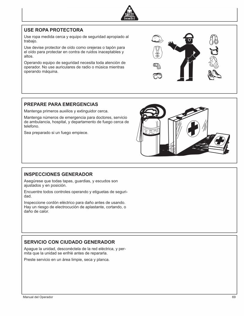
ManualdelOperador 69
USEROPAPROTECTORAUseropamedidacercayequipodeseguridadapropiadoaltrabajo.Usedeviseprotectordeoídocomoorejerasotapónparaeloídoparaprotectarencontraderuidosinaceptablesyaltos.Operandoequipodeseguridadnecesitatodaatencióndeoperador.Nouseauricularesderadioomúsicamientrasoperandomáquina.
INSPECCIONESGENERADORAsegúresequetodastapas,guardias,yescudossonajustadosyenposición.Encuentretodoscontrolesoperandoyetiguetasdeseguri-dad.Inspeccionecordóneléctricoparadañoantesdeusando.Hayunriesgodeelectrocucióndeaplastante,cortando,odañodecalor.
PREPAREPARAEMERGENCIASMantengaprimerosauxiliosyextinguidorcerca.Mantenganúmerosdeemergenciaparadoctores,serviciodeambulancia,hospital,ydepartamentodefuegocercadetelefono.Seapreparadosiunfuegoempiece.
SERVICIOCONCIUDADOGENERADORApaguelaunidad,desconécteladelaredeléctrica,yper-mitaquelaunidadseenfriéantesderepararla.Presteservicioenunárealimpie,secayplanca.

70 ManualdelOperador
SEÑALESDESEGURIDAD
34-1916-031607-E-F-S.
Using a generator indoors CAN KILL YOU IN MINUTES.
Generator exhaust contains carbon monoxide. This is apoison you cannot see or smell.
NEVER use inside a home or garage, EVEN IF doorsand windows are open.
Only use OUTSIDE and faraway from windows, doors, and vents.
DANGER DANGER PELIGROUtilizando un generador adentro PUEDE MATARLE EN MINUTOS. El escape de generador contiene monóxido de carbono. Este es un gas tóxico que usted no puede ver ni puede oler. Nunca utilice dentro de un hogar ni el garaje, INCLUSO SI puertas y ventanas estén abiertas.Solo utilice AFUERAS y lejos de ventanas abiertas, las puertas, y descargas.
L'utilisation d'un groupe électrogène à l'intérieur PEUT VOUS TUER ENQUELQUES MINUTES.Le gaz d'échappement du groupe électrogène contient de l'oxyde decarbone. C'est un gaz toxique que l'on ne peut pas voir ou sentir.Ne JAMAIS utiliser à l'intérieur d'une maison ou d'un garage, MÊME SI lesportes et fenêtres s'ont ouvertes.N'utiliser qu'à l'EXTÉRIEUR et bien éloignédes fenêtres, portes, et conduits d'aération.
GND34-0889
062104-ENG.
OPERATIONRead unit Operator's Manual carefully before operating this unit. Always make sure unit is level and properly grounded. Check engine oil before starting. START-UP:1. Open fuel valve.2. Move engine speed control to the run position.3. Turn the key to start position, release as soon as it starts.4. Allow unit to warm-up (2 min.) before applying load.5. Turn main breaker ON to main position.SHUT-DOWN:1. Remove all electrical loads by turning off and unplugging cords.2. Turn key to off position.3. Depress stop lever on engine speed control.4. Close fuel valve.*For recoil start see engine manual.
D'UTILISATION OPERACIÓNLire soigneusement le manuel de l'utilisateur avant de se servir de l'appareil. S'assurer toujours que l'appareil est sur une surface plane et qu'il est correctement relié à la terre. Vérifier le niveau d'huile du moteur avant le démarrage. *Pour un démarrage avec lanceur à rappel, voir le manuel du moteur. DEMARRAGE:1. Ouvrir la soupape de carburant de l'appareil ou du moteur.2. Placer la commande de régime du moteur en position de marche. 3. Tourner la clef jusquà la position de démarrage, puis la relâcher dés le démarrage.4. Permettre à l'appareil de tourner pendant deux (2) minutes pour qu'il se réchauffe avant d'appliquer une charge.5. Toumer l’disjoncteur de secteur sur la position marche (ON).ARRET:1. Supprimer toutes les charges électriques en éteignant et en débranchant les raccords électriques.2. Tourner la clef jusqu'à la position d'arrêt.3. Abaisser le levier d'arrêt de la commande de régime du moteur.4. Fermer la soupape de carburant sur l'appareil ou le moteur.
Lea manual de operador antes de operar esta unidad. Siempre asegúrese que unidad sea plana y conecte a tierra correcto. Revise el aceite de motor antes de empezando. *Para arranque de retroceso vea el manual de motor. OPERACIÓN:1. Abra válvula de comestible en unidad o motor.2. Mueva el control de la velocidad de motor a la posición de función. 3. Gire la llave a la posición de arranque, solte tan pronto como lo comienza. 4. Permite 2(min) para calentarse de la unidad antes de aplicando la carga.5. Dble cortacircuitos principal a posició de ON.ARRET:1. Quite todas cargas eléctricas como apagando y desenchufando las cuerdas.2. Gire el interruptor de la llave a la posición de OFF.3. Deprima la palanca de parada en el control de la velocidad de motor.4. Cierre válvula de comestible en unidad o motor.
TEST GFCI RECEPTICAL(S) BEFORE EACH USE. SEE OPERATORS MANUAL FOR INSTRUCTIONS.EXAMINEZ GFCI RECEPTICAL AVANT CHAQUE UTILISATION. VOIR LES OPÉRATEURS MANUELS POUR DES INSTRUCTIONS.PRUEBE GFCI RECEPTICAL ANTES DE CADA USO. VEA A LOS OPERADORES MANUALES PARA LAS INSTRUCCIONES.
NEUTRAL BONDED TO FRAMECOLLÉ NEUTRE À L’ARMATURECONSOLIDADO NEUTRAL AL MARCO
HOURMETERCOMPTEUR HORAIRECONTADOR HORARIO
20 AMPCIRCUIT BREAKER
DISJONCTEURDISYUNTOR
125 VOLT - 20 AMP125 VOLT - 20 AMPÈRE
125 VOLTIO - 20 AMPERIO
20 AMPCIRCUIT BREAKER
DISJONCTEURDISYUNTOR
125 VOLT - 20 AMP125 VOLT - 20 AMPÈRE
125 VOLTIO - 20 AMPERIO
20 AMPCIRCUIT BREAKER
DISJONCTEURDISYUNTOR
MAIN CIRCUIT BREAKERDISJONCTEUR DE SECTEUR
CORTACIRCUITOS PRINCIPAL
125/250 VOLT - 20 AMP125/250 VOLT - 20 AMPÈRE
125/250 VOLTIO - 20 AMPERIO
30 AMPCIRCUIT BREAKER
DISJONCTEURDISYUNTOR
125 VOLT - 30 AMP125 VOLT - 30 AMPÈRE
125 VOLTIO - 30 AMPERIO
34-2324 E-F-S 010908
34-1916
34-1676
34-2324
34-0889

ManualdelOperador 71
MandosMANDOS
A--Tanquede CombustibleB--PaneldeControl
D--TapadeCombustibleE--Puertodelllenadordelaceite
C--TapóndeDescargadel Aceite
D
C
A
B
E
F
F--Moefle

72 ManualdelOperador
PreparandolaGeneradorINSTRUCCIONESDECONEXIONATIERRAEsteequipodebeconectarseatierra.Laconexiónatierraproveeuncaminoderesistenciareducidaalacorrienteelétricaparareducirelriesgodechoque,encasodemal-funcionamientoofalla.
PELIGRO-LA CONEXIÓN INCORRECTA DELCONDUCTOR DE CONEXIÓN A TIERRA DELEQUIPO PUEDE RESULTAR EN UN RIESGODE ELECTROCUCIÓN. SI USTED TIENEDUDASACERCADESIELTOMACORRIENTEESTÁ CORRECTA-MENTE CONECTADO ATIERRA, CONSULTE CON UN ELECTRICISTACALIFICADOOPERSONALDESERVICIO.
Entodosloscasossedeberánutilizarlatuercaconorejetasyelterminaldelatomaatierrasituadosenelarmazónparaconectarelgeneradoraunafuentedetomaatierraadecuada.Sedeberáutilizaruncabledetamaño#8paraefectuarelcircuitodelatomaatierra.Conecteelterminaldelparalatomaatierraentrelaarandeladeseguridadylatuercaconorejetasyaprietelatuercacompletamente.Conectefirmementeelotroex-tremodelcableaunafuentedetomaatierraadecuada.EnelCódigoEléctricoNacional(<<NationalElectricCode>>)seindicanalgunosmétodosprácticosparaestablecerunabuenafuenteparalatomaatierra.Losejemplosqueseindicanacontinuaciónilustranalgunosdeestosmétodosparaestablecerunatomaatierraadec-uada.Comofuenteparalatomaatierrasepuedeutilizarunconductometálicosubterráneoparaelpasodeaguaqueseencuentreencontactodirectoconelsueloyquetengaunaextensiónmínimade10pies.Encasodequenodispongadeuntubosubterráneo,sepuedeutilizaruntuboobarraconunalongitudde8piescomofuenteparalatomaatierra.Eltubodeberíateneruntamañoestándarde3/4pulgadascomomínimo,ylasuperficieexteriordeberíaserresistentealacorrosión.Encasodequeseutiliceunabarradeaceroohierro,eldiámetrodelamismadeberíaserde5/8pulgadascomomínimo.Siseutilizaunabarradeunmaterialquenoseahierro,eldiámetrodelamismadebeserde1/2pulgadacomomínimo,ydebeestarclasificadocomounmaterialadec-uadoparaefectuarlatomaatierra.Introduzcalabarraoeltuboaunaprofundidadde8pies.Encasodequeelfondoempieceaserrocosoaunaprofundidadinferioracuatropies,deberáenterrareltuboolabarraenunazanja.Todaslasherramientaseinstrumentoseléctricosoperadosdesdeestegeneradordeberántenerlatomaatierraadecuada.Paraellosehabrádeutilizaruntercercable,elcualdeberátenerun<<AislamientoDoble>>.
SERECOMIENDAQUE:1. Usedispositivoseléctricosconcableseléctricosde3
espigas.2. Useuncabledeextensióncon3tomasyunenchufe
de3espigasenlosextremosopuestos,paraasegurarlacontinuidaddelaproteccióndelatomaatierraquevadesdeelgeneradorhastaelaparatoeléctrico.
GND34-0889
062104-ENG.

ManualdelOperador 73
Preparando la Generador
Lerecomendamosigualmentequesecumplancontodoslosreglamentosnacionales,regionalesylocalesrela-cionadosconlasespecificacionesdetomaatierraqueresultenaplicables.
CONMUTADORDETRANSFERENCIADELINEASiestegeneradorvaaserutilizadocomoserviciodereservaparacasosdeemergencia,seránecesarioqueincorporeunconmutadordetransferenciadelíneaentreelserviciodesuministroeléctricopúblicoyelgenerador.Elconmutadordetransferencianosóloevitaquelalíneadesuministroeléctricopúblicoalimentealgenerador,sinoqueademásimpidequeelgeneradoralimentealaslíneasdesuministrodelacompañíaeléctrica.Sepre-tendeconelloprotegeralaspersonasencargadasdelserviciocuandoseencuentrentrabajandoenunalíneaquepuedaestardañada.
ESTA INSTALACIÓN DEBERÍA SEREFECTUADA POR UN ELECTRICISTACERTIFICADO. SE DEBERA CUMPLIR CONTODOSLOSCÓDIGOSLOCALES.
CARGADECOMBUSTIBLE
CUIDADO: UTILICE SOLO EL PETROLEOESPECIFICADO DE MOTOR. OTROS OLEOSDE MOTORES PUEDEN AFECTAN ELALCANCE DE LA GARANTIA, LA CAUSACOMPONENTES QUE INTERNOS DE MOTORPARA AGARRAR, O PUEDEN CORTAR LAVIDADELMOTOR.
PREVENGALACONTAMINACIONDETIERRAY ESCOMBROS PARA EL PETROLEO DEMOTOR. LIMPIE CON CUIDADO LA TAPA DEEL PETROLEO/VARILLA GRADUADA Y ELAREACIRCUNDANTEANTESDEQUITAR LATAPA.
NUNCA MEZCLE LOS TIPOS DIFERENTESDEL PETROLEO DE MOTOR. ESTE AFECTOPUEDEADVERSAMENTELASPROPIEDADESDELUBRICARDELPETROLEODEMOTOR.
NUNCA RELLENO DEMASIADO. ELRELLENO DEMASIADO PUEDE TIENECOMO RESULTADO EL HUMO BLANCO DELESCAPE, FUNCIONA RAPIDA DE MOTOR ODAÑAINTERNO.
LAVISCOSIDADDELPETROLEODELMOTOCuidado:utilicesoloelpetroleoespecificadodemotor.
CATEGORÍASDESERVICIO•APIcategoríasdeservicioCDorarriba•ACEAcategoríasdeservicioE-3,E-4,andE-5
°F -4 14 32 50 68 86 104°C -20 -10 0 10 20 30 40
SAE 10W
SAE 20W
SAE 10W-30
SAE 15W-40
SAE 20
SAE 30
SAE 40
ELGRÁFICODELATEMPERATURA

74 ManualdelOperador
Preparando la Generador
•JASO(JaponésAutomóvilestándaresorganizacio-nes)
NOTAS:
1.Asegúresequeelpetróleodelmotor,loscontenedoresparaalmacenarelpetróleodelmotoryelequipoutilizadosparallenarelpetróleodelmotoreslibredesedimentosyagua.
2.Cambieelpetróleodelmotordespuésdelasprimeras50horasdelaoperaciónyentoncesencada200horasdespués.
3.Escogelaviscosidaddelpetróleobasadoenlatemperaturadelambientedondeelmotoresoperado.VeaalSEA-elgráficoenelGradodelServicioViscosidad.
4.Yanmarno recomiendaelusode las “añadiduras”delpetróleodelmotor.
LAVISCOSIDADDELPETROLEODELMOTOREscojalaviscosidadapropiadadelpetróleodelmotorbasadoenlatemperaturadelambienteyutiliceelSAE-elgráficodelGradodelServicioViscosidad.
PARALLENARCONPETROLEO1.Asegúresequeelmotoresplano.2.Quitelatapadelpetróleo/varilladecualquierubicacióny
enjuguecontelalimpia.3.Agreguelacantidadindicadadelpetróleodemotoren
cualquierunodelospuertosdemasilladepetróleodemotor.
4.Espereunminutoymire(cheque)elniveldelpetróleo.5.Agreguemáspetróleosinecesario.6.Reinsertecompletamentelatapadelpetróleo/varillay
aprieteamano.Demasiadoaprietecausaráeldaño.
LACAPACIDADDELPETROLEODELMOTOR(TIPICO)ElsiguienteeslacapacidaddelpetróleodemotorparavariosmotoresdeseriesdeYanmarLV..
CARGADECOMBUSTIBLE
ADVERTENCIA: EL COMBUSTIBLE ESEXPLOSIVO!
LA GASOLINA (NAFTA) ES UN FLUIDOEXTREMADAMENTE INFLAMABLE Y SUS VAPORES PUEDEN EXPLOTAR EN PRESENCIA
La tapa del Petróleo/Varilla Graduada
Los puertos de Masilla del Petróleo
MODEL# DIPSTICKUPPERLIMIT/LOWERLIMIT
L100V 1.7/1.06QT(1.6/1.0L)

ManualdelOperador 75
Preparando la Generador
DEUNACAUSADEIGNICIÓN.
GUARDEELCOMBUSTIBLEENRECIPIENTESAPROBADOS ESPECIALMENTE PARAELLO, EN LUGARES BIEN VENTILADOS, NOHABITADOS, Y ALEJADOS DE LLAMAS YCHISPAS.
NO CARGUE COMBUSTIBLE CON ELMOTOR CALIENTE O EN MARCHA, YA QUEUN DERRAME PODRÍA INCENDIARSE SIENTRA EN CONTACTO CON UNA PIEZAMUY CALIENTE O CON LA CHISPA DE UNABUJÍA.NOARRANCARELMOTORCERCADECOMBUSTIBLEDERRAMADO.
NO USE COMBUSTIBLE COMO LÍQUIDOLIMPIADOR.
ADVERTENCIA:NOCARGUEENEXCESOELTANQUEDECOMBUSTIBLE.DEJARESPACIOPARALAEXPANSIÓNDELCOMBUSTIBLE.
RECOMENDACIONESGENERALES•Compregasolinadedieselenpequeñascantidadesylatiendaencontenedoreslimpiosyaprobado.•Paraminimizardepositisdegomaensusistemadelcombustibleyparaasegurarcomenzarfácil,noutilizagasóleodejósobredelatemporadaanterior.•Noagregueelpetróleoalgasóleo.
ESPECIFICACIONESDEGASOLEOElgasóleodebeconformarseconlasespecificacionessiguientes.Lalistatienevariasespecificacionesmundia-lesparagasóleos.REQUISITOSTECNICOSADICIONALESDECOMBUSTIBLE.
•Elnúmerodecetanedecombustibledebeserigual a45omásalto.•Elcontenidodeazufrenodebeexceder0,5%por vlume.Menosde0,05%espreferido.•LosBio-Gasóleo-Veaabajo.•Nuncamezclequeroseno,elpetróleodelmotorque esviejooutilizado,nicombustiblesresidualesdel gasóleo.•Aguayelsedimentoenelcombustiblenodebe exceder0,05%porelvolumen.Siempremantenga limpioeltanquedelcombustibleyelequipoque manejaabastecedecombustible.•Elcombustibledelamalacalidadpuedereducirel desempeñodelmotory/oeldañodelacausaal motor.•Lasañadidurasparaabastecerdecombustibleno sonrecomendados.Algunasañadiduras delcombustiblepuedencausarpocorendimientode motor.ConsulteasuRepresentantede Yanmarparamásinformación.•ElcontenidodeCenizaparanoexceder0,01%por
LaespecificacióndeGasóle UbicaciónNo.2-D,No.1-D,ASTMD975-94 EEUUEN590:96 UniónEuropeaISO8217DMX InternacionalBS2869-A1orA2 ReinoUnidoJISK2204GradeNo.2 JapónKSM-2610 CoreaGB252 China

76 ManualdelOperador
Preparando la Generador
elvolumen.•Elcontenidoderesiduodelcarbónparanoexceder 0,35%porelvolumen.Menosde0,1%espreferido.•Elcontenidototaldearomáticonodebeexceder 35%porelvolumen.Menosde30%espreferido.•PAH(hidrocarburosaromáticosPolicíclicos)elcon tenidodebeestardebajode10%devolumen.•ElcontenidodeMetaldeNa,elMg,SiyAldeben serigualesomásbajoque1ppmmasivo.(El métododeanalisisdepruebadeJPI-5S-44-95).•Lalubricidad:MarcadeLlevedeWS1.4debeserel Max.0.018in(460p.m.)alapruebadeatHFRR.
COMBUSTIBLESDEBIO-DIESELEnEuropayenEstadosUnidos,asícomoalgunosotrospaíses,losrecursosdelpetróleono-mineralsebasaronelcombustiblecomoRME(elMetilodeSemilladecolzaEs-ter)ySOME(elMetilodelaSojaEster),colectivamenteconocidocomoFAMA(elMetilodeAcidograsoEster),sonutilizadoscomodeextensiónparaelpetróleomineraldegasóleos.Yanmarapruebaelusodebio-gasóleoquenoexcedenunamezclade5%(porelvolumen)delaFAMAcon95%(porelvolumen)delpetróleomineralaprobadoqueesderivadogasóleo.TalcombustiblebiológicoesconocidoenelmercadocomocombustiblesB5.
EstosgasóleosB5debenencontrarrequisitosespecificos.
1. El combustible biológico debe encontrar lasespecificacionesmínimasparaelpaísenelquesonutilizados.
EnEuropa,losbio-gasóleodebenconformarseconeleuropeo Estándar EN14214. En Estados Unidos, elcombustiblebiológicodebeconformarseconelASTMDEstándarnorteamericano-6751.
2. El combustiblebiológicodebesercompradosólodesuministradores de gasóleo que es reconocido y esautorizado.
LASPRECAUCIONESYCONCIERNECONRESPECTOALUSODECOMBUSTIBLEBIOLOGICO.
1.ElmetanollibreenlaFAMApuedetenercomoresultadolacorrosióndealuminioycomponentesdezincFIE.
2.Liberteaguaen laFAMApuede tenercomoresultadotapar de filtros de combustible y un aumento en elcrecimientodebacterias.
3.Laviscosidadaltaen temperaturasbajaspuede tenercomo resultado los problemas de transportar delcombustible,losataqueesenlabombadeinyección,yenlaatomizaciónpobredelrocíodebocadeinyección.
4.FAMApuedetenerelefectoadversoenalgunosElastómer(lasmateriasdelsello)ypuedetenercomoresultadomermadecombustibleydilucióndelmotorquelubricaelpetróleo.
5. Aún bio-gasóleo que se conforman con un estándar
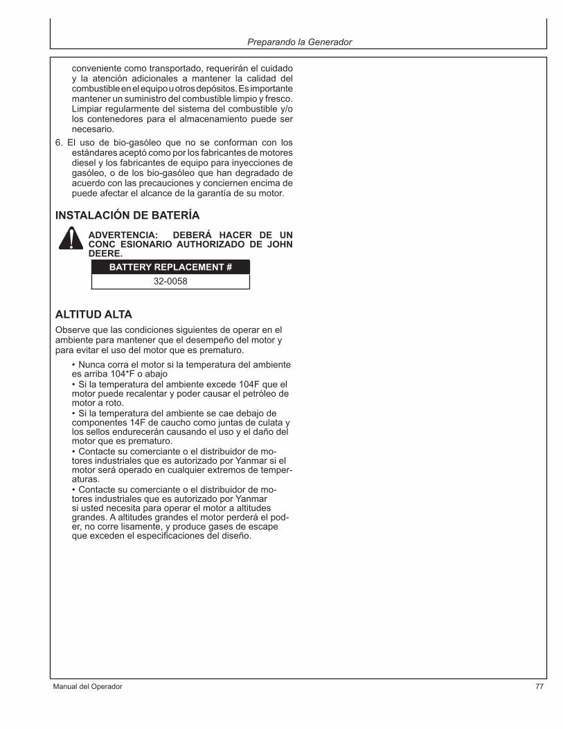
ManualdelOperador 77
Preparando la Generador
convenientecomotransportado,requeriránelcuidadoy la atención adicionales a mantener la calidad delcombustibleenelequipouotrosdepósitos.Esimportantemantenerunsuministrodelcombustiblelimpioyfresco.Limpiarregularmentedelsistemadelcombustibley/oloscontenedoresparaelalmacenamientopuedesernecesario.
6. El uso de bio-gasóleo que no se conforman con losestándaresaceptócomoporlosfabricantesdemotoresdieselylosfabricantesdeequipoparainyeccionesdegasóleo,odelosbio-gasóleoquehandegradadodeacuerdoconlasprecaucionesyconciernenencimadepuedeafectarelalcancedelagarantíadesumotor.
INSTALACIÓNDEBATERÍA
ADVERTENCIA: DEBERÁ HACER DE UNCONC ESIONARIO AUTHORIZADO DE JOHNDEERE.
ALTITUDALTAObservequelascondicionessiguientesdeoperarenelambienteparamantenerqueeldesempeñodelmotoryparaevitarelusodelmotorqueesprematuro.
•Nuncacorraelmotorsilatemperaturadelambienteesarriba104*Foabajo•Silatemperaturadelambienteexcede104Fqueelmotorpuederecalentarypodercausarelpetróleodemotoraroto.•Silatemperaturadelambientesecaedebajodecomponentes14Fdecauchocomojuntasdeculataylossellosendureceráncausandoelusoyeldañodelmotorqueesprematuro.•Contactesucomercianteoeldistribuidordemo-toresindustrialesqueesautorizadoporYanmarsielmotorseráoperadoencualquierextremosdetemper-aturas.•Contactesucomercianteoeldistribuidordemo-toresindustrialesqueesautorizadoporYanmarsiustednecesitaparaoperarelmotoraaltitudesgrandes.Aaltitudesgrandeselmotorperderáelpod-er,nocorrelisamente,yproducegasesdeescapequeexcedenelespecificacionesdeldiseño.
BATTERYREPLACEMENT#32-0058

78 ManualdelOperador
OPERACIÓNARRANQUEDERETROCESO
NOTA: Lea manual de operador antes de operar esta unidad. Siempre asegúrese que unidad sea plana y conecte a tierra correcto. Revise el aceite de motor antes de empezando.
COMIENZOELÉCTRICOCUIDADO: NUNCA UTILICE UNA AYUDACOMO ETER PARA COMENZAR EL MOTOR.ELDAÑOAMOTORRESULTARA.
Utiliceelprocedimientosiguienteparacomenzarelmotor.1.Aségureselapalancadelcombustibleesprendido.2.PongaelcontroldelavelocidaddemotoraCORRER/
FUNCIONAR3.Insertalallaveenelinterruptorclave.4.GirelallavealaderechaalaposicióndelCOMIENZO.
Suelte la llave tan pronto como el motor comienza.VolveráalaposiciondeON.
5.Sielmotornocomienza:A.Espere hasta queelmotor vengaa unaparada
completaantesustedprocuracomenzarlootravez.Comprometerelprincipiomientraselmotortodavíagira tendrá como resultado el dañoalmotor delprincipioyelvolante.
B. Espere por lomenos 30 segundos antes ustedprocura comenzarelmotor otra vez.Estapausapermitiráelvoltajedebateríapararecuperarparaprevenir el dañoalmotor del principio debidoalvoltajebajodebatería.
6. Permite la unidad a opere por dos (2)minutos paraprecalentamiento.
7. DoblecortacircuitosprincipalaposicióndeON(GEN-6000).
8. Examinerecipiente(s)deGFCIenlaunidad.Empujeelbotóndeexam.Elbotóndecolocardebesaltarynodebetenerpotenciaalrecipiente.Apliqueunacargade examinar o luz a cada recipiente para verificar.SI BOTÓN DE COLOCAR NO SALTE, NO USELOS RECIPIENTES. VEA CONCESIONARIO PARASERVICIOINMEDIATAMENTE.
9. Si recipientes examine correcto, empuje el botóndecolocarpara restablecerpotencia. Debeoírosentirun taconazo distincto cuando este es completo. SIRECIPIENTES NO COLOCAR CORRECTO, NOUSE RECIPIENTES. VEA CONCESIONARIO PARASERVICIOINMEDIATAMENTE.
PARADADELMOTOREL CUIDADO: PARA LA VIDA MAXIMA DELMOTOR, YANMAR RECOMIENDA QUE ALCERRE EL MOTOR HACIA ABAJO, USTEDPERMITE EL MOTOR PARA HOLGAZANEARSINLACARGADURANTE5MINUTOS.ESTOPERMITIRALOSCOMPONENTESDELMOTORQUE OPERAR EN TEMPERATURAS ALTAS,
Operación
La palanca de Control de la Velocidad de Motor
La perilla de Control de a Velocidad de Motor
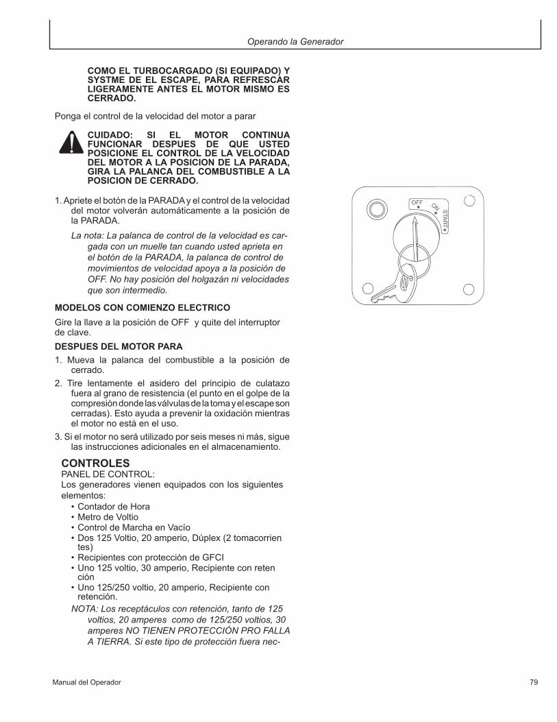
ManualdelOperador 79
Operando la Generador
COMOELTURBOCARGADO(SIEQUIPADO)YSYSTMEDEELESCAPE,PARAREFRESCARLIGERAMENTEANTESELMOTORMISMOESCERRADO.
Pongaelcontroldelavelocidaddelmotoraparar
CUIDADO: SI EL MOTOR CONTINUAFUNCIONAR DESPUES DE QUE USTEDPOSICIONEELCONTROLDELAVELOCIDADDELMOTORALAPOSICIONDELAPARADA,GIRALAPALANCADELCOMBUSTIBLEALAPOSICIONDECERRADO.
1.AprieteelbotóndelaPARADAyelcontroldelavelocidaddelmotorvolveránautomáticamentealaposicióndelaPARADA.La nota: La palanca de control de la velocidad es car-
gada con un muelle tan cuando usted aprieta en el botón de la PARADA, la palanca de control de movimientos de velocidad apoya a la posición de OFF. No hay posición del holgazán ni velocidades que son intermedio.
MODELOSCONCOMIENZOELECTRICOGirelallavealaposicióndeOFFyquitedelinterruptordeclave.DESPUESDELMOTORPARA1. Mueva la palanca del combustible a la posición de
cerrado.2. Tire lentamente el asidero del principio de culatazo
fueraalgranoderesistencia(elpuntoenelgolpedelacompresióndondelasválvulasdelatomayelescapesoncerradas).Estoayudaaprevenirlaoxidaciónmientraselmotornoestáeneluso.
3.Sielmotornoseráutilizadoporseismesesnimás,siguelasinstruccionesadicionalesenelalmacenamiento.
CONTROLESPANELDECONTROL:Losgeneradoresvienenequipadosconlossiguienteselementos:•ContadordeHora•MetrodeVoltio•ControldeMarchaenVacío•Dos125Voltio,20amperio,Dúplex(2tomacorrien tes)•RecipientesconproteccióndeGFCI•Uno125voltio,30amperio,Recipienteconreten ción•Uno125/250voltio,20amperio,Recipientecon retención.NOTA: Los receptáculos con retención, tanto de 125
voltios, 20 amperes como de 125/250 voltios, 30 amperes NO TIENEN PROTECCIÓN PRO FALLA A TIERRA. Si este tipo de protección fuera nec-
80 ManualdelOperador
Operando la Generador
esaria en estos receptáculos, se deben instalar disyuntores extemos. En la sección de “Interrup-tor de circuitos por falla a tierra” se puede obtener más información sobre el tema.
ADVERTENCIA:NO SUPERAR LA CARGANOMINAL DE UN RECEPTÁCULO. LOSRECEPTÁCULOSESTÁN PROTEGIDOSCONTRA SOBRECARGA ELÉCTRICAMEDIANTE INTERRUPTORESTERMOMAGNÉTICOS CON BOTÓN DEREPOSICIÓN. SI UN INTERRUPTOR SEDISPARA, DESCUBRIR Y SOLUCIONAR ELPROBLEMAANTESDEVOLVERACONECTARELINTERRUPTOR.
CONTROLESCONTADORDEHORAS:Elcontadordehorasdeestosgeneradoresmideeltiempoquelamáquinaestáenservicio.Estoesmuyútilparaprogramartareasdemantenimiento.Enelcuadrodemantenimientoperiódicoseofrecensugerenciasparalaprogramacióndelmantenimiento.
METRODEVOLTIO:Estosgeneradoressonequipadosconunmetrodevoltio.Elmetrodevoltioseusaamonitorizarlaunidadparavoltajecorrecto.
TRITURADORPRINCIPALEstosgeneradoresseequipandeundisyuntorprincipalqueprotejahastaadentrounacondicióndesobrecarga.Estetrituradorprincipaldebeser“ON”paraquecualquierenergíaseaextraídadelaunidad.
ELTAMAÑODECABLEEldañoalequipopuederesultardelvoltajebajo.Porlotanto,paraprevenirgotaexcesivadelvoltajeentreelgeneradoryelequipo,elcabledebeserdelcalibradoradecuadoparalalongitudqueesutilizada.Elgráficodelaseleccióndecabledalaslongitudesmáximasdecableparavarioscalibradoresdealambrequepuedellevaradecuadamentelascargasqueesmostrado.
CARGASDELMOTORELECTRICO:Unadelascaracterísticasdelosmotoreseléctricoscomunesesque,enelmomentodearrancar,necesitanmulitplicarselsveceslapotenciarequeridaparasufunc-ionamiento.Ud.puedeutilizerestatablaparacalcularlosvatiosrequeridosparaelarranquedelosmotoreseléctri-cosde“CODEG”(CODIGOG).
PRECAUCIÓN: EN EL CASO DE QUE UNMOTOR NO ARRANQUE O NO ALCANCELA VELOCIDAD NECESARIA PAR SUFUNCIONAMIENTO, DEBERÁ APAGARINMEDIATAMENTE EL EQUIPO ELÉCTRICOO EL INSTRUMENTO PARA EVITAR DAÑOSA LOS MISMOS. SIEMPRE DEBERÁCOMPROBAR LOS REQUISITOS DELINSTRUMENTO O EQUIPO ELÉCTRICO QUESE VAA UTILIZAR, EN COMPARACIÓN CONLACAPACIDADNOMINALDELGENERADOR.
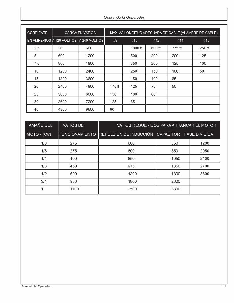
ManualdelOperador 81
Operando la Generador
CORRIENTE CARGAENVATIOS MAXIMALONGITUDADECUADADECABLE(ALAMBREDECABLE)
ENAMPERIOSA120VOLTIOS A240VOLTIOS #8 #10 #12 #14 #16
2.5 300 600 1000ft 600ft 375ft 250ft
5 600 1200 500 300 200 125
7.5 900 1800 350 200 125 100
10 1200 2400 250 150 100 50
15 1800 3600 150 100 65
20 2400 4800 175ft 125 75 50
25 3000 6000 150 100 60
30 3600 7200 125 65
40 4800 9600 90
TAMAÑODEL VATIOSDE VATIOSREQUERIDOSPARAARRANCARELMOTOR
MOTOR(CV) FUNCIONAMIENTO REPULSIÓNDEINDUCCIÓN CAPACITORFASEDIVIDIDA
1/8 275 600 850 1200
1/6 275 600 850 2050
1/4 400 850 1050 2400
1/3 450 975 1350 2700
1/2 600 1300 1800 3600
3/4 850 1900 2600
1 1100 2500 3300

82 ManualdelOperador
SÍNTOMA PROBLEMA SOLUCIONES
Elmotornoarranca. Interruptordemotorestáen Dobleinterruptordemotoraposición posicióndeOFF. deON. Eltanquedecombustibleestávacío. Lleneeltanquecomolasinstruccio nesdeestemanual.
Nohaysalidadevoltaje Arranquedecontroldemarcha Coloquecontroldemarchaenvacío.delgenerador. envacío. Seriedecordonoextensiones Revisecapabilidadesdeseriesde inadecuados. cordonoextensionesensecciónde Controles;TamañodeCableeneste manual. Consultarconunconcesionariode JohnDeere.
LocalizacióndeFallas

ManualdelOperador 83
MANTENIMIENTO
MANTENERLIMPIASLASABERTURASDEVENTILACIÓN.Mantengaelgeneradorlimpiado.Norociarconagua.
Revisarperiódicamentelostornillosypernos,yajustarlosenlamedidadelonecesario(véaseelcuadrodemanten-imientoperiódico).
REGISTRODEPRUEBASDEDISYUNTORESDEFALLAATIERRA:Aligualqueotrosdispositivosdeseguridad,elGFCIincorporadoaestosgeneradoresrequiereunainspecciónmensualparacomprobarquefuncionecorrectamente.ParasometerelGFCIaprueba,sigalasinstruccionesyregistrelafechadelapruebaenelcuadroquevéaselailustraciónuramásabajo.
1. Acontinuación,oprimaelbotón<<TEST>>(prueba),lo cual hará que se levante el botón ><<RESET>>(posición inicial). Esto interrumpirá el suministro deelectricidadhaciaambostomacorrientessdelenchufedoble.Compruebelainterrupciónunalámparaencadatomacorrientes.
ADVERTENCIA: SI EL BOTÓN DECOLOCAR NO SALTE AFUERA, NO USE EL
ServicioRECIPIENTE(S). VEA UNCONCESIONARIOAUTORIZADO DE JOHN DEERE PARASERVICIOINMEDIATAMENTE.
2. SielresultadodelapruebaindicaqueelGFCIfuncionacorrectamente,conéctelonuevamentealaelectricidadpresionando FIRMEMENTE el botón <<RESET>>(posicióninicial)hastaqueescucheconclaridadunclicosientaquehavueltoacaerenposición.
3. LaaltavibraciónoelefectodecargasmecánicasseveraspuedenhacerqueelGFCIsedispare.SIELGFCISEDISPARAPORSIMISMOENCUALQUIERMOMENTO,vuelvaaponerloenlaposicióninicialypóngaloapruebasegúnseindicaenlospuntosanteriores1y2.
4. Paraelsegundodisyuntordefallaatierra,repetirlospasos1a3.
ADVERTENCIA: AUNQUE LOSPROCEDIMIENTOS DE EXAMEN ARRIBAINDICARÁN OPERACIÓN CORRECTO ENUNGENERADORBAJO TIERRAOA TIERRAINCORRECTO, EL GENERADOR TIENE QUETOMAR A TIERRA DE INSTRUCCIONES DECONEXIÓN A TIERRA QUE ESTÁ EN UNALISTA DE PARA GFCI OPERE CORRECTO YPARA PROTEJAR EL USADOR DE FALLASELÉCTRICAS.
Año Ene. Feb. Mar. Apr. Mayo Jun. Jul. Ago. Sep. Oct. Nov. Dic.
NOTA: Existen casos en los que el GFCI no ofrece protección contra el peligro de contacto con la electricidad, EJEMPLO: Si une apersona toca dos conductores o más de un cordón eléctrico defectuoso y no se encuentra en contacto con la tierra, puede entonces experimentar un contacto con la electricidad. Dado que no existe una vía para que pase la corriene de pérdida a tierra, el GFCI no funcionará y puede ocasionar daños graves.
El GFCI es simplemente una característica de seguridad adicional. No existe ningún dispositivo que pueda reemplazar las buenas medidas de seguridad en las tareas eléctricas y el mantenimiento adecuado de los cables, del equipo y de las conexiones.

84 ManualdelOperador
Servicio
MOTOR:Elmotordeestegeneradorestágobernadoparafuncio-naravelocidadespróximasa3600RPM(60Hz)durantelamarchadentrodelrangodecargasadmisibles.Lavelocidaddelmotorantesdelaaplicacióndelacargaeslevementemayorquelavelocidadbajacarga,ynormal-menteestáreguladaa3750RPM.
ADVERTENCIA:NOALTERARELMECANISMODEL GOBERNADOR DE VELOCIDAD DE LAMÁQUINA, NI CAMBIAR SU CALIBRACIÓNPARA EXPERIMENTAR, NI ABRIR ALMÁXIMO EL ACELERADOR PARA TRATARDE GENERAR MÁS POTENCIA ELÉCTRICA,YA QUE SE PUEDE DAÑAR EL EQUIPO OCAUSARACCIDENTESPERSONALES.
LA REGULACIÓN DEL GOBERNADOR DEVELOCIDAD SE DEBE LLEVAR A CABOÚNICAMENTE EN UN CONCESIONARIO DEJOHNDEERE.
CAMBIODEACEITEDELMOTOR:Cambieelaceitedespuésdelasprimeras50horasdefuncionamiento,ydespuéshaceriocada200horas.
DESAGÜEDELASIGUIENTEMANERA:
1.Aségureseelmotoresnivel.2. Comience el motor y lo traiga a la temperatura de
operar.3.Pareelmotor.4. Quite la tapa del petróleo/varilla graduada permitir el
petróleodelmotorparadesaguarmásfácilmente.
5.Coloqueuncontenedorbajoelmotorparareunirelpetróleoquenoesutilizado.
6.Quite el tapón del desaguadero que es situado en elfondodelbloquedelcilindro.Permitaelpetróleoparadesaguar.
7.Despuésdetododelpetróleohadesaguadodelmotor,instalaeltapóndeldesaguaderoyaprietaa14-17lbs.delp.
8.Dispongaapropiadamentedetodopetróleoquenoesutilizado.
PARALLENARDELPETROLEO:
1.Aségureseelmotoresnivel.2.Quitelatapadelpetróleo/varillagraduada.3.Agreguelacantidadindicadadelpetróleodemotoren
cualquier uno de los puertos demasilla del petróleodemotor.
4.Espereunminutoyverifiqueelniveldelpetróleo.5.Agreguemássiesnecesario.6. Reinserte completamente la tapa del petróleo/varilla
graduadayaprieteamano.

ManualdelOperador 85
PRECAUCIÓN: EL ACEITE PODRÍA ESTARMUY CALIENTE. TOMAR PRECAUCIONESPAR EVITAR LESIONES PERSONALES.DESECHAR EL ACEITE USADO SEGÚN LOSREGLAMENTOSVIGENTES.
FILTRODEAIRE:
ADVERTENCIA: LIMPIE EL ELEMENTO DELFILTRO EN UN ÁREA BIEN VENTILADA.ASEGURARSE DE QUE NO HAYANELEMENTOS QUE PRODUZCAN CHISPAS NILLAMASENLASCERCANÍASDELLUGARDETRABAJO, INCLUYENDO LLAMAS PILOTO.NOUSECOMBUSTIBLESNI SOLVENTESDEBAJOPUNTODEIGNICIÓNPARALIMPIARELELEMENTODELFILTRO,YAQUESEPONRÍAGENERARUNINCENDIOOUNAEXPLOSIÓN.
PRECAUCIÓN: NO PONGA EL MARCHA ELMOTORSINELFILTRODEAIRE,YAQUESEPODRÍANCAUSARSERIASAVERÍAS.
Eldesempeñodelmotoresafectadoadversamentecuandoelelementodellimpiadordeaireesatascadoconpolvo.Estésegurolimpiarperiódicamenteelelementodelfiltrodeaire.
1.Quitelapalomilla.2.Quitelatapadellimpiadordeaire.3.Quitelapalomilla.4.Quiteel elementodel limpiadordeaire yel elemento
exterioresdeespuma.
5.Soplaalgúnaireporamboselementosqueutilizan42-71airedePSIcomprimieronparaquitarlaspartículas.Utilicelapresiónmásbajadeaireparaquitarelpolvosindañarloselementos.
6..Sicualquieradeloselementostieneneldaño,reemplaceambos de los elementos (los elementos no vendenindividualmente)
7.Limpieeldentrodelatapadellimpiadordeaire.8. Instaleelelementodelimpiadordeaireenelcasode
limpiadordeaire.9.Desliceelelementoexteriordeespumasobreelelemento
delimpiadordeaire.10. Instale la palomilla y apriete a mano. Apretando
demasiado de la palomilla dañará la asamblea delimpiadordeaire.
11.Instalelatapadellimpiadordeaire.12. Instale la palomilla y apriete a mano. Apretando
demasiado de la palomilla dañará la asamblea delimpiadordeaire.
CUADRODEMANTENIMIENTOPERIÓDICO:Elmantenimientodeunmotoraintervalosregulares
Tapa de Espuma
PalomillaTapa
El elemento deLimpiador de Aire
Palomilla
Servicio

86 ManualdelOperador
Servicio
asegurasufuncionamientosatisfactorioporlargosperio-dos.Enelsiguientecuadrodemantenimientoperiódicoseindicanloselementosainspeccionarymantener,ylafrecuenciadeejecucióndelastareas,queestámarcadaconunpuntoalineadoconlatareainvolucrada.
NOTA: Para ciertas tareas de regulación y calibración es necesario utilizar herramientas y equipos es-peciales. Para calibrar la velocidad en vacío y de servicio, es sumamente conveniente contar con un tacómetro electrónico.

ManualdelOperador 87
Servicio
Diario Cada Cada Cada Antesde
25horas 100horas 200horas almacenar
Inspeccionarniveldecombistible •
Inspeccionarniveldeaceitedelmotor •
Inspeccionarestadodetornillosytuercas •
Inspecciónparadetectarpérdidas •
Inspeccióndelimpiezadealetasdecilindroytapadecilindros •
Inspeccióndeniveldeelectrolitodebatería •
Inspeccióndelíneadecombustible(cambiarsifueranecesario) •
Limpiezadelelementodeespumadelfiltrodeaire(**) •
Ajustedetuercasytornillos (*) •
Cambiodeaceitedelmotor(*) •
Limpiezadelfiltrodecombustible •
Cambiodelelementodepapeldelfiltrodeaire(**) •
Limpiezadealetasdecilindroy tapadecilindros(**) •
Limpiezaycalibracióndeluzdebujía •
Agregarestabilizadordecombustible •
Dejarlaunidadmarchahastaconsumirelcombustible •
*Ejecutarestatareasdespuésdelasprimerascincuenta(50)horasdeservicio,ydespuésconlafrecuenciaindicada.**Aumentarlafrecuenciasilaunidadtrabajaenambientesmuypolvorientos.
NOTA: Estas tareas se deben ejecutar con las herramientas adecuadas. A menos que el usuario tenga el cono-cimiento y las herramientas necesarias, llevar la unidad al servicio técnico de un concesionario de John Deere.
ANOTENÚMEROSERIEEscribanúmerodemodelo,numeroseriedemáquina(veaetiquetadenúmeroserie(A)enilustraciónyfechadecompraenespaciosabajo.Suconcesarionecesitaestainformacióncuandoordenandopartes.
Num.demodelo __________________________________________
Num.seriedemáquina_____________________________________
Fechadecompra__________________________________________(llenedecomprador)
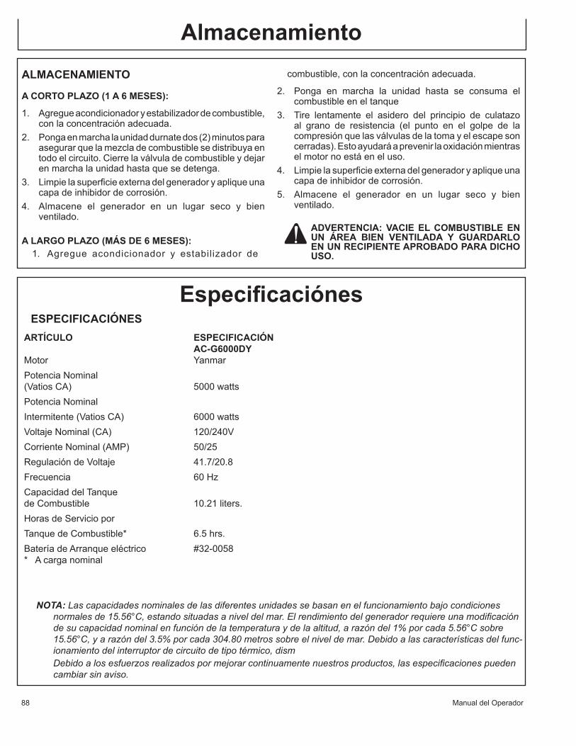
Service
88 ManualdelOperador
ALMACENAMIENTO
ACORTOPLAZO(1A6MESES):
1. Agregueacondicionadoryestabilizadordecombustible,conlaconcentraciónadecuada.
2. Pongaenmarchalaunidaddurnatedos(2)minutosparaasegurarquelamezcladecombustiblesedistribuyaentodoelcircuito.Cierrelaválvuladecombustibleydejarenmarchalaunidadhastaquesedetenga.
3. Limpielasuperficieexternadelgeneradoryapliqueunacapadeinhibidordecorrosión.
4. Almacene el generador en un lugar seco y bienventilado.
ALARGOPLAZO(MÁSDE6MESES):1. Agregue acondicionador y estabilizador de
Almacenamientocombustible,conlaconcentraciónadecuada.
2. Ponga en marcha la unidad hasta se consuma elcombustibleeneltanque
3. Tire lentamente el asidero del principio de culatazoal grano de resistencia (el punto en el golpe de lacompresiónquelasválvulasdelatomayelescapesoncerradas).Estoayudaráaprevenirlaoxidaciónmientraselmotornoestáeneluso.
4. Limpielasuperficieexternadelgeneradoryapliqueunacapadeinhibidordecorrosión.
5. Almacene el generador en un lugar seco y bienventilado.
ADVERTENCIA:VACIEELCOMBUSTIBLEENUN ÁREA BIEN VENTILADA Y GUARDARLOENUNRECIPIENTEAPROBADOPARADICHOUSO.
ESPECIFICACIÓNESARTÍCULO ESPECIFICACIÓN AC-G6000DYMotor YanmarPotenciaNominal(VatiosCA) 5000wattsPotenciaNominalIntermitente(VatiosCA) 6000wattsVoltajeNominal(CA) 120/240VCorrienteNominal(AMP) 50/25RegulacióndeVoltaje 41.7/20.8Frecuencia 60HzCapacidaddelTanquedeCombustible 10.21liters.HorasdeServicioporTanquedeCombustible* 6.5hrs.BateríadeArranqueeléctrico #32-0058*Acarganominal
Especificaciónes
NOTA: Las capacidades nominales de las diferentes unidades se basan en el funcionamiento bajo condiciones normales de 15.56°C, estando situadas a nivel del mar. El rendimiento del generador requiere una modificación de su capacidad nominal en función de la temperatura y de la altitud, a razón del 1% por cada 5.56°C sobre 15.56°C, y a razón del 3.5% por cada 304.80 metros sobre el nivel de mar. Debido a las características del func-ionamiento del interruptor de circuito de tipo térmico, dism
Debido a los esfuerzos realizados por mejorar continuamente nuestros productos, las especificaciones pueden cambiar sin aviso.
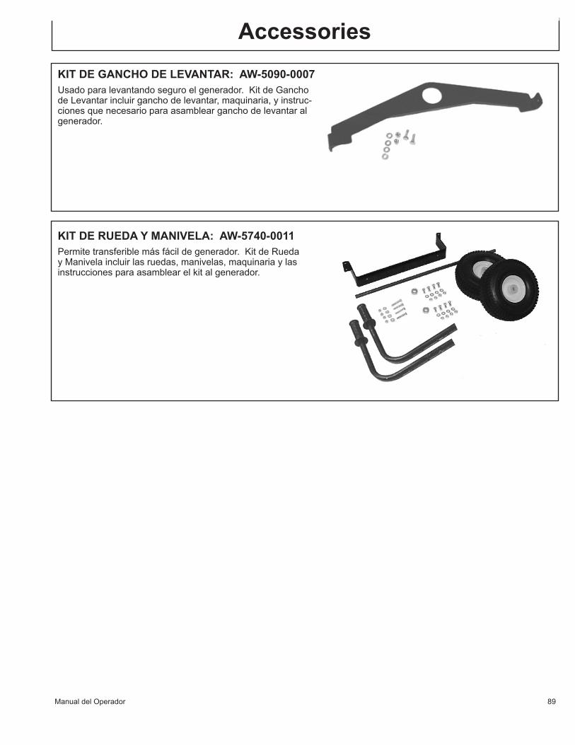
ManualdelOperador 89
Accessories
KITDERUEDAYMANIVELA:AW-5740-0011Permitetransferiblemásfácildegenerador.KitdeRuedayManivelaincluirlasruedas,manivelas,maquinariaylasinstruccionesparaasamblearelkitalgenerador.
KITDEGANCHODELEVANTAR:AW-5090-0007Usadoparalevantandoseguroelgenerador.KitdeGanchodeLevantarincluirganchodelevantar,maquinaria,yinstruc-cionesquenecesarioparaasamblearganchodelevantaralgenerador.

90 ManualdelOperador
GARANTÍA
DECLARACIÓNDEGARANTÍA
JohnDeeregarantizaquetodaslaspiezas(exceptoaquellasalasquesehacereferenciaabajo),desunuevageneradorlibresdedefectosenmaterialesymanodeobradurantelosperiodossiguientes:
Pordos(2)añoapartirdelafechaoriginaldecompra.
Laspiezasdefectuosasquenoestánsujetasadeteriorocausadoporelusoseránreparadasoreemplazadasanuestraopciónduranteelperiododegarantía.Entodocaso,elreembolsoestálimitadoalpreciodecomprapagado.
EXCLUSIONES
1. Elmotorestácubiertobajounagarantíaporseparadoquesurespectivofabricante ofreceyquedasujetoalostérminosestablecidosendichagarantía.2. Estagarantíanocubrelaspiezasquesondañadasdebidoaldesgastenormal,aplicación
incorrecta,usoerroneo,operaciónenotroquerecomendado.Lafaltadeseguirfuncionarrecomendadoylosprocedimientosdemantenimientoanularlagarantíatambién.
3. Elusodeotraspiezasdereparacióngenuinasdelfabricanteanularálagarantía.4. Laspiezasvueltas,pagadoporadelantadoanuestrafábricaoauncentrodeservicio
autorizadodeJohnDeereseránexaminadasy reemplacengratuitamentesi estanencontradasparaserdefectuosasyconformeagarantía.Nohaygarantíasqueextiendenmásdeladescripcióndelacaradeesto.Debajodeningunascircunstanciaselfabricantetendráalgoresponsibilidaddeperdidadeusodelaunidad,laperdidadetiempoodealquiler,lainconveniencia,laperdidacomercialolosdañosconsecuentes.
PARASERVICIOOCONSIDERACIONDELAGARANTIACONSULTECON:Mi-T-M®Corporation/8650EnterpriseDrive,Box50/Peosta,IA52068-0050
Telefono:1-877-JD-KLEEN/(1-877-535-5336)Fax:563-556-1235Lunes-Viernes8:00a.m.-5:00p.m.CST

ManualdelOperador 91
DECLARACIONDEGARANTIADEEMISIONESDECALIFORNIASUSDERECHOSDEGARANTIAYOBLIGACIONESLaTabladeRecursosAéreosdeCaliforniayJohnDeereestanfelicesparaexplicarlagarantíadesistemadecontrol
deemisionesensupequeñomotortodoterreno(SORE).EnCalifornia,PequeñosMotoresTodoterrenoquesonnuevostienequeserdiseñado,paraserconstruidoyparaserequipadoparaencontrarlosestándaresrigurososdeEstadodenieblaespesaconhumolimitada.JohnDeeredebejustificarelsistemadeemisionescontrolaensuPequeñoMotorTodoterrenoporlosespaciosdetiempolistóabajoproporcionadonohahabidoabuso,eldescuidonielmantenimientoimpropiosdesuPequeñoMotorTodoterreno.
Susistemadecontroldeemisionespuedeincluirpartescomoelsistemadecarburadoroinyección,laslíneasdecombustible y el sistemade ignición.Tambiénpuede incluirmangas, las abrazaderas, los conectores y otroscomponentesasociados.
Dóndeexisteunwarrantabledecondición,JohnDeererepararásuPequeñoMotorTodoterrenoenningúncostoaustedincluyediagnóstico,laspartesytrabaja.
ALCANCEDEGARANTIAPORFABRICANTEEstesistemadecontroldeemisionestienegarantíadurantedosaños.Sicualquierpartequeesrelacionadaaemisiones
ensumotoresdefectuosa,laparteseráreparadaoseráreemplazadaporJohnDeere.RESPONSABILIDADESDEGARANTIAPARAELPROPIETARIO-ComoelpropietariodelPequeñoMotorTodoterreno,ustedesresponsablededesempeñodelmantenimientonecesario
quelistóensumanualdepropietario.JohnDeererecomiendaqueustedretengatodosrecibosquecubrenensumanualdepropietario.JohnDeererecomiendaqueustedretengatodosrecibosquecubrenmantenimientoensuPequeñoMotorTodoterreno,peroenJohnDeerenopuedenegardegarantíaparalafaltaderecibossolo.
-ComoelpropietariodelPequeñoMotorTodoterrenoqueusteddebesaberqueJohnDeerepuedenegarquealcancedegarantíasisuPequeñoMotorTodoterrenoounapartefallanacausadeabuso,eldescuidooelmantenimientoimpropiasolasmodificacionesquenotienenaprobación.
-UstedesresponsabledepresentarsuPequeñoMotorTodoterrenoalcentrodedistribuciónocentrodereparacionesqueesautorizadoporlaCorporacióndeJohnDeere
8650EnterpriseDrive,Peosta,IA52068(Mi-T-M)enprontoqueunproblemaexista.Lasreparacionesdegarantíadebensercompletadasenunacantidadrazonabledetiempo,noexceder30días.
Siustedtieneunapreguntaconrespectoasualcancedegarantía,usteddebecontactarelDepartamentodeServicioparaClientesdeJohnDeereen1-800-553-9053.
ALCANCEGENERALDEGARANTIADEEMISIONES-SóloCalifornia-JohnDeerejustificaalúltimocompradorycadacompradorsubsiguientequeelPequeñoMotorTodoterreno(1)ha
sidodiseñado,hasidoconstruidoyhasidoequipadoparaconformarsecontodasregulacionesaplicables;y(2)eslibrededefectosenmateriasyhabilidadquecausaqueelfracasodeunapartejustificadaconformeseconesasregulacionespuedesercomoaplicablealostérminosycondicionesquesonindicadosabajo.
(a)Elperíododeganantíaempiezaenlafechaqueelmotoresentregadoaunúltimocompradoroprimerocolocadoenelservicio.Elperíododegarantíaesdosaños.
(b)Sujetoaciertascondicionesyexcursionesindicócomoabajo,lagarantíaenemisionesrelacionópartessonasí:(1)Ningunapartequetienegarantíaquenoesplanificadoparaelreemplazocomomantenimientonecesarioensu
manualdepropietarioesjustificadoparaelperíododegarantíaindicadoarriba.Silapartefalladuranteelperíododealcancedegarantía,laparteseráreparadaoseráreemplazadaporJohnDeeresegúnlasubdivisión(4)abajo.Cualquieratalpartequeesreparadaoesreemplazadobajogarantíaserájustificadoparaelrestodelperiod.
(2)Cualquierpartequetienegarantíaqueesplanificadosóloparainspecciónregularensumanualdepropietarioesjustificadoparaelperíododegarantíaqueesindicadaarriba.Cualquieratalpartereparóoreemplazóbajogarantíaserájustificadoporelperíodorestantedegarantía.
(3)Cualquierpartequetienegarantíaqueesplanificadoparaelreemplazocomomantenimientonecesarioensumanualdepropietarioesjustificadoparaelespaciodetiempoantesdelaprimerafechaplanificadadereemplazoparaesaparte.Silapartefallaantesdelprimerreemplazoplanificado,laparteseráreparadaoseráreemplazadaporJohnDeeresegúnlasubdivisión(4)abajo.Cualquieratalpartequehasidoreparadaohasidoreemplazadobajo

92 ManualdelOperador
garantíaserájustificadoparaelrestodelperíodoantesdelprimerpuntoplanificadodereemplazoparalaparte.(4)Repareoelreemplazodealgunapartejustificadabajolasprovisionesdegarantíaenestedebeserrealizadoen
unaestacióndegarantíaenningunacargaalpropietario.(5)Lasprovisionesenesto,losserviciosdegarantíanireparaciónseránproporcionadosentodosnuestroscentros
dedistribuciónquesonotorgadaslaconcesiónparaatenderalosmotoressujetos.(6)Elpropietarionodebesercargadoparatrabajodiagnósticoquellevaaladeterminaciónqueunapartejustificada
esdehechodefectuosa,contaldequetaltrabajodiagnósticosearealizadoenunaestacióndegarantía.(7)JohnDeereesresponsablededañosdelaproximidadaotroscomponentesdemotorqueescausadoporun
fracasobajogarantíadealgunapartejustificada.(8)Atravésdelperíododegarantíademotorquesonindicadosarriba,JohnDeeremantendráqueunsuministrode
partesjustificadassuficientesparaencontrarlademandaesperadaparatalespartes.(9)Cualquierrepuestopuedeserutilizadoeneldesempeñodecualquiermantenimientodegarantíaoreparacionesy
debeserproporcionadosincargaalpropietario.TalusonoreducirálasobligacionesdegarantíadeJohnDeere.10.LaspartesquesonañadidasomodificadoquenosoneximidosporlaTabladeRecursosAéreosnopuedenser
utilizado.Elusodecualquierpartesdeno-eximióquesonañadidasomodificadosporelúltimocompradorserárazónparanopermitiroreclamosqueaceptandegarantía.JohnDeerenoseráresponsablealfracasodeautorizacionesdepartesquetienegarantíacausadoporelusodeunapartesdeno-eximióquetienencosasextrasohansidomodificado.
(C)PartesquetienenGarantíaLareparaciónoelreemplazodecualquierpartequetienegarantíadeotromodoelegibleparaelalcancedegarantía
miesexcluidodetalalcancedegarantíasiJohnDeeredemuestraqueelmotorhasidoabusado,elcomponentequetiene
(1)SistemadeMedirCombustible(A)Carburadorypartesinternos(y/oelreguladordepresiónosistemadeinyección)(B)ReaccióndeproporcióndeAire/Combustibleysistemadecontrol,siaplicable(C)Sistemadeenriquecimientofríodecomienzo,siaplicable(D)Regulador(combustiblequeesgaseoso,siaplicable(2)SistemadeInduccióndeAire(A)TomaMúltiple,siaplicable(B)FiltrodeAire(3)SistemadeIgnición(A)bujías(B)Magnetoosistemadeigniciónelectrónica(C)Sistemadeavancedechispa/retarda,siaplicable(4)Agotamúltiple,siaplicable(5)SistemadeEvaporación(A)LíneadeCombustible(B)Accesoriosdelíneadecombustible

ManualdelOperador 93

ManufacturedbyMi-T-M8650EnterpriseDrive,PeostaIA52068
563-556-7484/Fax563-556-1235