
AC -...
12
82 70 62 70 9 57.7 30.5 22.7 4.5 11 35 5 x 11.7 = [58.5] 6 4.5 27 31 45 82 69.5 7 68 6 9 Pic. 1 Pic. 3 Pic. 2 Pic. 4 L1 L2 L3 N (PEN) M-Bus 3 × 230/400 VAC 431951040d Terminals E1 and E2 Connection for the control signal from the ripple control receiver for tariff switching
Transcript of AC -...

82
27
62
4,5
6
70
65 x
11,7
= (58
,5)
768
4,59
30,5
9
11
57,7
22,7
35
69,5
3162
70
9
57.7
30.5
22.7
4.5
1135
5 x
11.7
= [5
8.5]
6
4.527
31
45
82
69.5
768
6
9
Pic. 1 Pic. 3
Pic. 2 Pic. 4
T2total T2part.
U(V)
T1part . P(kW )T1tota l
Error
L3
I(A)
L1
L2
Class B
ALE
3D5F
L1
L2
L3N
(PEN)
M-Bus
3 ×
230
/400
VA
C 43
1951
040d
Terminals E1 and E2 Connection for the control signal from the ripple control receiver for tariff switching
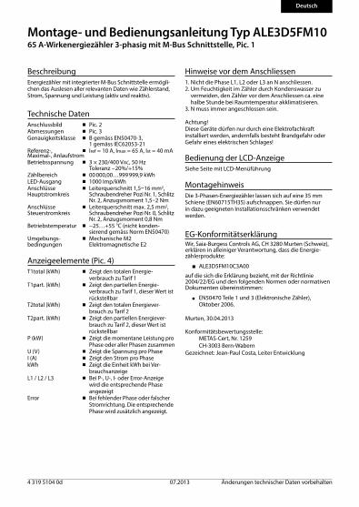
Montage- und Bedienungsanleitung Typ ALE3D5FM1065 A-Wirkenergiezähler 3-phasig mit M-Bus Schnittstelle, Pic. 1
BeschreibungEnergiezähler mit integrierter M-Bus Schnittstelle ermögli-chen das Auslesen aller relevanten Daten wie Zählerstand, Strom, Spannung und Leistung (aktiv und reaktiv).
Technische DatenAnschlussbild ■ Pic. 2Abmessungen ■ Pic. 3Genauigkeitsklasse ■ B gemäss EN50470-3, 1 gemäss IEC62053-21Referenz-, ■ Iref = 10 A, Imax = 65 A, Ist = 40 mAMaximal-, AnlaufstromBetriebsspannung ■ 3 × 230/400 VAC, 50 Hz Toleranz −20%/+15%Zählbereich ■ 00 000,00…999 999,9 kWhLED-Ausgang ■ 1000 Imp/kWh Anschlüsse ■ Leiterquerschnitt 1,5–16 mm2, Hauptstromkreis Schraubendreher Pozi Nr. 1, Schlitz Nr. 2, Anzugsmoment 1,5–2 NmAnschlüsse ■ Leiterquerschnitt max. 2,5 mm2, Steuerstromkreis Schraubendreher Pozi Nr. 0, Schlitz Nr. 2, Anzugsmoment 0,8 NmBetriebstemperatur ■ −25…+55 °C (nicht konden-
sierend gemäss Norm EN50470)Umgebungs- ■ Mechanische M2bedingungen Elektromagnetische E2
Anzeigeelemente (Pic. 4)T1total (kWh) ■ Zeigt den totalen Energie-
verbrauch zu Tarif 1T1part. (kWh) ■ Zeigt den partiellen Energie-
verbrauch zu Tarif 1, dieser Wert ist rückstellbar
T2total (kWh) ■ Zeigt den totalen Energiever-brauch zu Tarif 2
T2part. (kWh) ■ Zeigt den partiellen Energiever-brauch zu Tarif 2, dieser Wert ist rückstellbar
P (kW) ■ Zeigt die momentane Leistung pro Phase oder aller Phasen zusammen
U (V) ■ Zeigt die Spannung pro PhaseI (A) ■ Zeigt den Strom pro PhasekWh ■ Zeigt die Einheit kWh bei Ver-
brauchsanzeigeL1 / L2 / L3 ■ Bei P-, U-, I- oder Error-Anzeige
wird die entsprechende Phase angezeigt
Error ■ Bei fehlender Phase oder falscher Stromrichtung. Die entsprechende Phase wird zusätzlich angezeigt.
Hinweise vor dem Anschliessen 1. Nicht die Phase L1, L2 oder L3 an N anschliessen.2. Um Feuchtigkeit im Zähler durch Kondenswasser zu
vermeiden, den Zähler vor dem Anschliessen ca. eine halbe Stunde bei Raumtemperatur akklimatisieren.
3. N muss immer angeschlossen sein.
Achtung!Diese Geräte dürfen nur durch eine Elektrofachkraftinstalliert werden, andernfalls besteht Brandgefahr oder Gefahr eines elektrischen Schlages!
EG-Konformitätserklärung Wir, Saia-Burgess Controls AG, CH 3280 Murten (Schweiz), erklären in alleiniger Verantwortung, dass die Energie-zählerprodukte:
■ ALE3D5FM10C3A00
auf die sich die Erklärung bezieht, mit der Richtlinie 2004/22/EG und den folgenden Normen oder normativen Dokumenten übereinstimmen:
■ EN50470 Teile 1 und 3 (Elektronische Zähler), Oktober 2006.
Murten, 30.04.2013
Konformitätsbewertungsstelle: METAS-Cert, Nr. 1259 CH-3003 Bern-Wabern Gezeichnet: Jean-Paul Costa, Leiter Entwicklung
Deutsch
MontagehinweisDie 3-Phasen-Energiezähler lassen sich auf eine 35 mm Schiene (EN60715TH35) aufschnappen. Sie dürfen nur in dazu geeigneten Installationsschränken verwendet werden.
Bedienung der LCD-AnzeigeSiehe Seite mit LCD-Menüführung
4 319 5104 0d 07.2013 Änderungen technischer Daten vorbehalten

Saia-Burgess Controls AG Bahnhofstrasse 18 I CH-3280 Murten I Schweiz T +41 26 / 672 72 72 I F +41 26 / 672 74 99 [email protected] I www.sbc-support.com
Deutsch
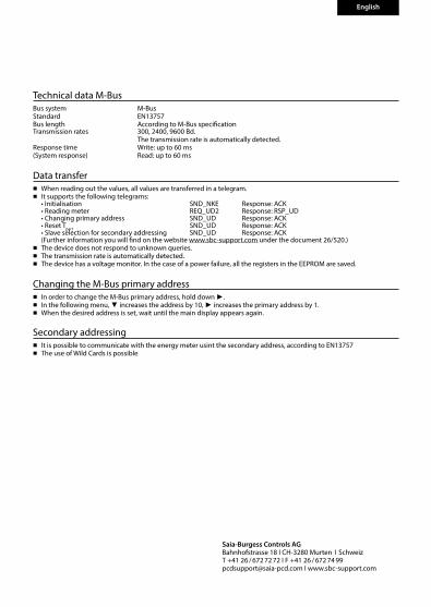
Technische Daten M-BusBus System M-BusNorm EN13757Bus Länge Gemäss M-Bus SpezifikationÜbertragungsraten 300, 2400, 9600 Bd. Die Übertragungsrate wird automatisch erkannt. Reaktionszeit Schreiben: bis 60 ms(Systemreaktionszeit) Lesen: bis 60 ms
Datenübertragung■ Beim Auslesen der Werte werden alle Werte in einem Telegramm übertragen.■ Es werden folgende Telegramme unterstützt:
• Initialisierung SND_NKE Antwort: ACK • Zähler auslesen REQ_UD2 Antwort: RSP_UD • Primäradresse ändern SND_UD Antwort: ACK • Reset Tpart SND_UD Antwort: ACK • Slave-Auswahl für die Sekundär-Adresse SND_UD Antwort: ACK (Detailierte Angaben erhalten Sie auf der Website www.sbc-support.com unter dem Dokument 26/520.)■ Das Gerät antwortet nicht auf unbekannte Abfragen. ■ Die Übertragungsrate wird automatisch erkannt. ■ Das Gerät hat eine Spannungsüberwachung. Im Falle eines Spannungsverlusts werden alle Register im EEPROM
gespeichert.
Ändern der M-Bus Primäradresse■ Um die M-Bus Adresse zu ändern halten Sie 3 Sek ► gedrückt.■ Im folgenden Menü, ▼ erhöht die Adresse um 10, ► erhöht die Primäradresse um 1.■ Wenn die gewünschte Primäradresse eingestellt ist, warten Sie bis das Hauptmenü wieder erscheint.
Sekundär-Adresse■ Mithilfe der Sekundär-Adresse ist es möglich mit dem Energiezähler zu kommunizieren, gemäss der Norm EN13757.■ Die Verwendung von Wild Cards ist möglich.

Assembly and operating instructions Type ALE3D5FM10 65 A Three-phase active power energy meter with M-Bus interface, Pic. 1
DescriptionEnergy meter with M-Bus interface enables the reading of all relevant data like meter reading, electricity, voltage and power (active and reactive).
Indicating elements (Pic. 4)T1total (kWh) ■ Shows total consumption Tariff 1T1part. (kWh) ■ Shows partial consumption for
Tariff 1, this value is resettableT2total (kWh) ■ Shows total consumption Tariff 2T2part. (kWh) ■ Shows partial consumption for
Tariff 2, this value is resettableP(kW) ■ Shows the instantaneous power
per phase or all phasesU(V) ■ Shows the voltage per phaseI(A) ■ Shows the current per phasekWh ■ Shows the unit kWh when the
consumption is displayedL1 / L2 / L3 ■ For P-, U-, I- or Error display, the
corresponding phase is displayedError ■ In case of missing phase or wrong
current direction. The correspond-ing phase is additionally displayed.
Technical dataConnection ■ Pic. 2diagramDimensions ■ Pic. 3Accuracy class ■ B according to EN50470-3, 1 according to IEC62053-21Reference, Maxi- ■ Iref = 10 A, Imax = 65 A, Ist = 40 mAmum, initial currentoperating voltage ■ 3 × 230/400 VAC, 50 Hz Tolerance −20%/+15%Counting range ■ 00 000,00…999 999,9 kWhLED-Ouptut ■ 1000 Imp/kWh Connections ■ Conductor cross-section 1,5–16 mm2, Main circuit screwdriver pozi no. 1, slot no. 2, torque 1,5–2 NmConnections ■ Conductor cross-section max. 2,5 mm2, Control circuit screwdriver pozi no. 0, slot no. 2, torque 0,8 NmOperating ■ −25…+55°C (noncondensing temperature according standard EN50470)Environment ■ Mechanical M2 Electromagnetic E2
Notes before connecting 1. Do not connect L1, L2 or L3 to N2. In order to avoid moisture in the meter due to condensa-
te build-up, acclimatise the meter at room temperature for about half an hour before connecting.
3. N must always be connected.
Attention!These devices must only be installed by a professional electrician, otherwise there is the risk of fire or the risk of an electric shock.
Declaration of Conformity CEWe, Saia-Burgess Controls Ltd., CH 3280 Murten (Switzer-land), herewith declare, on our own responsibility that the products:
■ ALE3D5FM10C3A00
which this certificate refer to, are in accordance with the directive 2004/22/EG (MID) and the following standards:
■ EN50470 parts 1 and 3 (electronic meter), of October 2006.
Murten, 30.04.2013
Conformity Assessment Body: METAS-Cert, Nr. 1259 CH-3003 Bern-Wabern Signed: Jean-Paul Costa, Head of development
English
Installation instructionsThe three-phase energy meter can be attached to a 35 mm rail (EN60715TH35). The meter can be used only in installation cabinets.
Operation of the LCD displaySee page with LCD menu navigation
4 319 5104 0d 07.2013 Subject to change without notice
Saia-Burgess Controls AG Bahnhofstrasse 18 I CH-3280 Murten I Schweiz T +41 26 / 672 72 72 I F +41 26 / 672 74 99 [email protected] I www.sbc-support.com
Technical data M-BusBus system M-BusStandard EN13757 Bus length According to M-Bus specification Transmission rates 300, 2400, 9600 Bd. The transmission rate is automatically detected.Response time Write: up to 60 ms(System response) Read: up to 60 ms
Data transfer■ When reading out the values, all values are transferred in a telegram.■ It supports the following telegrams: • Initialisation SND_NKE Response: ACK • Reading meter REQ_UD2 Response: RSP_UD • Changing primary address SND_UD Response: ACK • Reset Tpart SND_UD Response: ACK • Slave selection for secondary addressing SND_UD Response: ACK (Further information you will find on the website www.sbc-support.com under the document 26/520.)■ The device does not respond to unknown queries. ■ The transmission rate is automatically detected. ■ The device has a voltage monitor. In the case of a power failure, all the registers in the EEPROM are saved.
Changing the M-Bus primary address■ In order to change the M-Bus primary address, hold down ►.■ In the following menu, ▼ increases the address by 10, ► increases the primary address by 1. ■ When the desired address is set, wait until the main display appears again.
Secondary addressing■ It is possible to communicate with the energy meter usint the secondary address, according to EN13757■ The use of Wild Cards is possible
English
Italiano
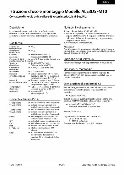
Istruzioni d’uso e montaggio Modello ALE3D5FM10Contatore d’energia attiva trifase 65 A con interfaccia M-Bus, Pic. 1
DescrizioneIl contatore d’energia con interfaccia M-Bus integrata consente la lettura tutti i dati rilevanti, quali registro del contatore, corrente, tensione e potenza (attiva e reattiva).
Dati tecniciSchema di ■ Pic. 2collegamentoDimensioni ■ Pic. 3d’ingombroClasse di ■ B secondo EN50470-3,precisione 1 secondo IEC62053-21Corrente di riferi- ■ Iref = 10 A, Imax = 65 A, Ist = 40 mAmento, massima, di spuntoTensione ■ 3 × 230/400 VAC, 50 Hz d’esercizio Tolleranza −20%/+15%Capacità di ■ 00 000,00…999 999,9 kWhconteggioUscita LED ■ 1000 Imp/kWh Morsetti ■ Sezione conduttori 1,5–16 mm2, circuito principale cacciavite pozi nr. 1, a taglio nr. 2, coppia di serraggio 1,5–2 NmMorsetti ■ Sezione conduttori max. 2,5 mm2, circuito di comando cacciavite pozi nr. 0, a taglio nr. 2, coppia di serraggio 0,8 NmTemperatura ■ −25…+55°C (assenza di condensa d’esercizio secondo la norma EN50470)Ambienti ■ meccanici M2 elettromagnetici E2
Elementi a display (Pic. 4)T1total (kWh) ■ indica il consumo totale alla tariffa 1T1part. (kWh) ■ indica il consumo parziale alla
tariffa 1; questo valore è azzerabileT2total (kWh) ■ indica il consumo totale alla tariffa 2T2part. (kWh) ■ indica il consumo parziale alla
tariffa 2; questo valore è azzerabileP(kW) ■ indica la potenza istantanea per
ciascuna fase o per tutte le fasiU(V) ■ indica la tensione per ciascuna fase I(A) ■ indica la corrente per ciascuna fasekWh ■ indica il consumo rilevato in kWh L1 / L2 / L3 ■ è la fase interessata per P, U, I o ErroreError ■ In caso di mancanza di una fase
o di direzione della corrente sbagliata. Viene visualizzata la fase interessata
Dichiarazione di conformità CENoi, Saia-Burgess Controls SA, CH 3280 Morat (Svizzera), dichiarammo in nostra propria responsabilità che i prodotti:
■ ALE3D5FM10C3A00
di quali si riferisce questa dichiarazione rispondono alla direttiva 2004/22/CE (MID) e alle normative seguente:
■ normativa EN50470 Parte 1 e 3 (Contatori elettronici). Octobre 2006
Murten, 30.04.2013
Organismi di valutazione della conformità: METAS-Cert, Nr. 1259 CH-3003 Bern-WabernFirmato: Jean-Paul Costa, capo dello sviluppo
Note per il collegamento 1. Non collegare la fase L1, L2 o L3 a N.2. Per evitare la presenza di umidità nel contatore in
seguito alla formazione di acqua di condensa, prima del collegamento lasciare il contatore per circa mezz’ora a temperatura ambiente
3. N deve sempre essere collegato.
Attenzione!Questi apparecchi devono essere installati esclusivamente da elettricisti specializzati, onde evitare rischi di incendio o pericoli di scosse elettriche!
Istruzioni di montaggioI contatori di energia trifase si installano su guida da 35 mm (EN60715TH35). Devono essere installati solo in quadri o centralini
Funzione del display LCDPer ulteriori dettagli vedi pagina LCD con menù guidato
4 319 5104 0d 07.2013 Soggetto a modifiche senza preavviso
Saia-Burgess Controls AG Bahnhofstrasse 18 I CH-3280 Murten I Schweiz T +41 26 / 672 72 72 I F +41 26 / 672 74 99 [email protected] I www.sbc-support.com
Italiano
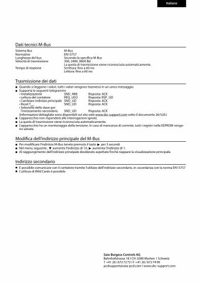
Dati tecnici M-BusSistema Bus M-BusNormative EN13757Lunghezza del bus Secondo la specifica M-BusVelocità di trasmissione 300, 2400, 9600 Bd. La quota di trasmissione viene riconosciuta automaticamente.Tempo di reazione Scrittura: fino a 60 ms Lettura: fino a 60 ms
Trasmissione dei dati■ Quando si leggono i valori, tutti i valori vengono trasmessi in un unico messaggio.■ Supporta le seguenti telegrammi: • Inizializzazione SND_NKE Risposta: ACK • Lettura del contatore REQ_UD2 Risposta: RSP_UD • Cambiare indirizzo principale SND_UD Risposta: ACK • Reset Tpart SND_UD Risposta: ACK • Selezione dello slave per
l'inirizzamento secondario SND_UD Risposta: ACK (Informazioni dettagliate sono disponibili sul sito web www.sbc-support.com sotto il documento 26/520.)■ L’apparecchio non risponderà alle interrogazioni ignote.■ La quota di trasmissione viene riconosciuta automaticamente.■ L’apparecchio ha un monitoraggio della tensione. In caso di mancanza di corrente, tutti i registri nella EEPROM vengo-
no salvate.
Modifica dell’indirizzo principale del M-Bus■ Per modificare l’indirizzo M-Bus tenete premuto il tasto ► per 3 secondi. ■ Nel menu seguente ‚ ▼ aumenta l’indirizzo di 10, ► aumenta l’indirizzo di 1. ■ Al raggiungimento dell’indirizzo prinzipale desiderato aspettate finché riappare la visualizzazione principale.
Indirizzo secondario■ E possibile comunicare con il contatore tramite l'utilizzo dell'indirizzo secondario, in cocordanza con la norma EN13757■ L'utilizza di Wild Cards é possibile

Francais
4 319 5104 0d 07.2013 Sous réserve de modifications sans préavis
Instructions de montage et d’exploitation ALE3D5FM10Compteur d’énergie active triphasé 65 A avec interface M-Bus, Pic.1
DescriptionLes compteurs d’énergie avec interface M-Bus permettent le relevé de toutes les données importantes telles que la valeur du compteur, le courant, la tension et la puissance (active et réactive).
Caractéristiques techniquesSchéma de ■ Pic. 2raccordementDimensions ■ Pic. 3Classe de ■ B selon EN50470-3, précision 1 selon IEC62053-21 Courant de ■ Iref = 10 A, Imax = 65 A, Ist = 40 mA référence, maximal, de démarrageTension de service ■ 3 × 230/400 VAC, 50 Hz Tolérance −20%/+15%Plage de comptage ■ 00 000,00…999 999,9 kWhSortie LED ■ 1000 Imp/kWhBranchements ■ Section de conducteur 1,5…16 mm2, Circuit d’alimentation tournevis pozi n° 1, plat n° 2, couple de serrage 1,5…2 NmBranchements ■ Section de conducteur maximal Circuit de commande 2,5 mm2, tournevis ozi n° 0, plat n° 2, couple de serrage 0,8 NmTempérature de ■ −25…+55°C (sans condensation service selon la norme EN50470)Environnement ■ mécanique M2 electromagnétiques E2
Eléments d’affichage (Pic. 4)T1total (kWh) ■ Indique la consommation totale
tarif 1T1part. (kWh) ■ Indique la consommation partielle
au Tarif 1, cette valeur est réinitiali-sable
T2total (kWh) ■ Indique la consommation totale tarif 2
T2part. (kWh) ■ Indique la consommation partielle au Tarif 2, cette valeur est réinitiali-sable
P(kW) ■ Indique la puissance instantanée par phase ou de toutes les phases
U(V) ■ Indique la tension par phaseI(A) ■ Indique le courant par phasekWh ■ Indique l’unité kWh pour l’affi-
chage de consommationL1 / L2 / L3 ■ En cas d’affichage P, U, I ou Error, la
phase correspondante s’afficheError ■ En cas d’absence de phase ou
de sens de courant inversé. La phase correspondante s’affiche également.
Déclaration de conformité CE Nous, Saia-Burgess Controls SA, CH 3280 Morat (Suisse), déclarons sous notre propre responsabilité que les produits:
■ ALE3D5FM10C3A00
pour lesquels cette déclaration se référe sont conformes à la directive 2004/22/CE (MID) et aux normes suivantes:
■ EN50470 Parties 1 et 3 (Compteurs électroniques). Octobre 2006
Murten, 30.04.2013
Organismes d’évaluation de la conformité: METAS-Cert, Nr. 1259 CH-3003 Bern-Wabern Signé : Jean-Paul Costa, Directeur du Développement
Remarque préalable au raccordement 1. Ne pas raccorder la phase L1, L2 ou L3 à N.2. Afin d’éviter la formation de condensation dans le
compteur, laisser celui-ci s’acclimater pendant env. une demi heure à la température ambiante du local.
3. N doit toujours être connecté.
Attention!Ces appareils doivent être uniquement installés par un spécialiste en électricité pour éviter tout risque d’incendie ou d’électrocution !
Instructions de montage Les compteurs d’énergie triphasé peuvent être encliquetés sur un rail de 35 mm (EN60715TH35). Ils ne peuvent être utilisés que dans des armoires électriques.
Utilisation de l’écran LCDVoir la page avec le guidage de menu LCD
Saia-Burgess Controls AG Bahnhofstrasse 18 I CH-3280 Murten I Schweiz T +41 26 / 672 72 72 I F +41 26 / 672 74 99 [email protected] I www.sbc-support.com
Francais
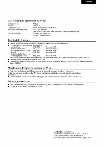
Caractéristiques techniques du M-BusSystème de bus M-BusNorme EN13757Longueur du bus Selon la spécification du M-BusVitesse de communication 300, 2400, 9600 Bd. La vitesse de communication est déterminée automatiquement.Temps de réaction Ecriture : jusqu’à 60 ms Lecture : jusqu’à 60 ms
Transfert de données■ Lors du relevé des valeurs, toutes les valeurs sont transmises par un télégramme.■ Les télégrammes suivants sont compatibles: • Initialisation SND_NKE Réponse : ACK • Relever le compteur REQ_UD2 Réponse : RSP_UD • Modifier l’adresse primaire SND_UD Réponse : ACK • Reset Tpart SND_UD Réponse : ACK • Selection de l'esclave pour
l'adressage secondaire SND_UD Réponse : ACK (Des informations détaillées sont disponibles sur le site web www.sbc-support.com sous le document 26/520.)■ L’appareil ne répond pas aux requêtes inconnues. ■ L’appareil est doté d’une surveillance de la tension. En cas de perte de tension, tous les données sont sauvegardées
dans l‘EEPROM.
Modification de l’adresse primaire de M-Bus■ Pour modifier l’adresse du M-Bus, maintenir la touche ► appuyée pendant 3 secondes.■ Dans le menu suivant, la touche ▼ incrémente l’adresse de 10 et la touche ► incrémente l’adresse primaire de 1.■ Lorsque l’adresse primaire souhaitée est réglée, attendre que le menu principal s‘affiche de nouveau.
Adressage secondaire■ Il est possible de communiquer avec le compteur grâce à l'adresse secondaire, selon la norme EN13757.■ L'usage de Wild Card est également possible
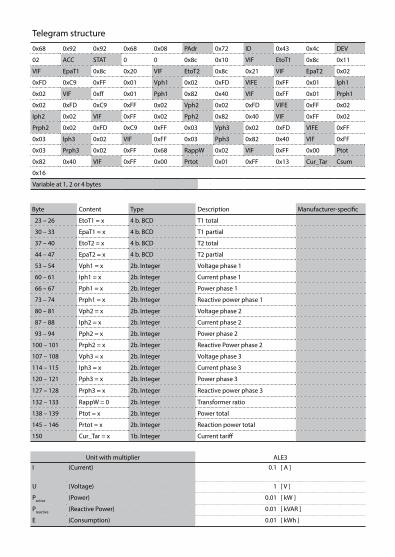
Unit with multiplier ALE3
I (Current) 0.1 [ A ]
U (Voltage) 1 [ V ]
Pactive (Power) 0.01 [ kW ]
Preactive (Reactive Power) 0.01 [ kVAR ]
E (Consumption) 0.01 [ kWh ]
Telegram structure
0x68 0x92 0x92 0x68 0x08 PAdr 0x72 ID 0x43 0x4c DEV
02 ACC STAT 0 0 0x8c 0x10 VIF EtoT1 0x8c 0x11
VIF EpaT1 0x8c 0x20 VIF EtoT2 0x8c 0x21 VIF EpaT2 0x02
0xFD 0xC9 0xFF 0x01 Vph1 0x02 0xFD VIFE 0xFF 0x01 lph1
0x02 VIF 0xff 0x01 Pph1 0x82 0x40 VIF 0xFF 0x01 Prph1
0x02 0xFD 0xC9 0xFF 0x02 Vph2 0x02 0xFD VIFE 0xFF 0x02
Iph2 0x02 VIF 0xFF 0x02 Pph2 0x82 0x40 VIF 0xFF 0x02
Prph2 0x02 0xFD 0xC9 0xFF 0x03 Vph3 0x02 0xFD VIFE 0xFF
0x03 lph3 0x02 VIF 0xFF 0x03 Pph3 0x82 0x40 VIF 0xFF
0x03 Prph3 0x02 0xFF 0x68 RappW 0x02 VIF 0xFF 0x00 Ptot
0x82 0x40 VIF 0xFF 0x00 Prtot 0x01 0xFF 0x13 Cur_Tar Csum
0x16
Variable at 1, 2 or 4 bytes
Byte Content Type Description Manufacturer-specific
23 – 26 EtoT1 = x 4 b. BCD T1 total
30 – 33 EpaT1 = x 4 b. BCD T1 partial
37 – 40 EtoT2 = x 4 b. BCD T2 total
44 – 47 EpaT2 = x 4 b. BCD T2 partial
53 – 54 Vph1 = x 2b. Integer Voltage phase 1
60 – 61 Iph1 = x 2b. Integer Current phase 1
66 – 67 Pph1 = x 2b. Integer Power phase 1
73 – 74 Prph1 = x 2b. Integer Reactive power phase 1
80 – 81 Vph2 = x 2b. Integer Voltage phase 2
87 – 88 Iph2 = x 2b. Integer Current phase 2
93 – 94 Pph2 = x 2b. Integer Power phase 2
100 – 101 Prph2 = x 2b. Integer Reactive Power phase 2
107 – 108 Vph3 = x 2b. Integer Voltage phase 3
114 – 115 Iph3 = x 2b. Integer Current phase 3
120 – 121 Pph3 = x 2b. Integer Power phase 3
127 – 128 Prph3 = x 2b. Integer Reactive power phase 3
132 – 133 RappW = 0 2b. Integer Transformer ratio
138 – 139 Ptot = x 2b. Integer Power total
145 – 146 Prtot = x 2b. Integer Reaction power total
150 Cur_Tar = x 1b. Integer Current tariff
I(A)U(V)Error
T1part. T2total T2part.T1total P(kW)
L1
L3
L2
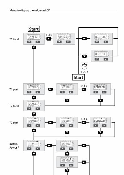
Start
T1 total
T1 part
T2 total
T2 part
> 3 s
> 3 s
Menu to display the value on LCD
Instan. Power P
I(A)U(V)Error
T1part. T2total T2part.T1total P(kW)
L1
L3
L2
I(A)U(V)Error
T1part. T2total T2part.T1total P(kW)
L1
L3
L2
> 3 s
> 20 s
access control
presence
alarming
energy- management
combined heat and power station
protocol (VISI+)
energy
lift
cooling
heating
ventilation
temperature
setpoint
lighting
shade control
sanitation
sheduler (VISI+)
trending
remote alarming (VISI+)
visualization (VISI+)
building
traffic control
water treatment
IT / Data
Logistic system
tele- communication
graphic editor (VISI+)
I(A)U(V)Error
T1part. T2total T2part.T1total P(kW)
L1
L3
L2
Start
I(A)U(V)Error
T1part. T2total T2part.T1total P(kW)
L1
L3
L2
I(A)U(V)Error
T1part. T2total T2part.T1total P(kW)
L1
L3
L2
I(A)U(V)Error
T1part. T2total T2part.T1total P(kW)
L1
L3
L2
I(A)U(V)Error
T1part. T2total T2part.T1total P(kW)
L1
L3
L2
I(A)U(V)Error
T1part. T2total T2part.T1total P(kW)
L1
L3
L2
I(A)U(V)Error
T1part. T2total T2part.T1total P(kW)
L1
L3
L2
I(A)U(V)Error
T1part. T2total T2part.T1total P(kW)
L1
L3
L2
I(A)U(V)Error
T1part. T2total T2part.T1total P(kW)
L1
L3
L2
I(A)U(V)Error
T1part. T2total T2part.T1total P(kW)
L1
L3
L2
I(A)U(V)Error
T1part. T2total T2part.T1total P(kW)
L1
L3
L2
I(A)U(V)Error
T1part. T2total T2part.T1total P(kW)
L1
L3
L2
I(A)U(V)Error
T1part. T2total T2part.T1total P(kW)
L1
L3
L2
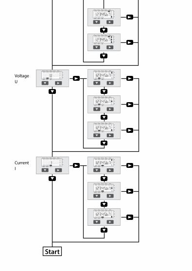
Voltage U
Current I
Start
I(A)U(V)Error
T1part. T2total T2part.T1total P(kW)
L1
L3
L2
I(A)U(V)Error
T1part. T2total T2part.T1total P(kW)
L1
L3
L2
I(A)U(V)Error
T1part. T2total T2part.T1total P(kW)
L1
L3
L2
I(A)U(V)Error
T1part. T2total T2part.T1total P(kW)
L1
L3
L2
I(A)U(V)Error
T1part. T2total T2part.T1total P(kW)
L1
L3
L2
I(A)U(V)Error
T1part. T2total T2part.T1total P(kW)
L1
L3
L2
I(A)U(V)Error
T1part. T2total T2part.T1total P(kW)
L1
L3
L2
I(A)U(V)Error
T1part. T2total T2part.T1total P(kW)
L1
L3
L2