AC & DC Stackers - Presto...
30
AC & DC Stackers (B, D, E, and PS Series) Installation,Operation & Service Manual Model Number ___________________ Serial # _________________________ Date placed in service _____________ IMPORTANT: READ CAREFULLY BEFORE INSTALLING OR OPERATING LIFT JUNE 2016
Transcript of AC & DC Stackers - Presto...

AC & DCStackers
(B, D, E, and PS Series)
Installation,Operation& Service Manual
Model Number ___________________Serial # _________________________Date placed in service _____________
IMPORTANT: READ CAREFULLYBEFORE INSTALLING OR OPERATING LIFT
JUNE 2016

OWNER’S MANUAL Page 2 AC & DC STACKERS
This manual was current at the time of printing. To obtain the latest, most updated version, please contact the Customer Service Department or go to our website: www.PrestoLifts.com -- you will find a complete list of current owner’s manuals to print.
Presto Lifts Limited Warranty PolicyPresto Lifts warrants all of its products against defects in the welded structural frame and, if applicable, scissor legs from faulty material and workmanship for a period of five (5) years from the date of invoice.
All batteries and battery chargers have a limited warranty against defects in faulty material and work-manship for a ninety (90) day period from the date of invoice through Presto Lifts. All other components have a limited warranty against defects in faulty material and workmanship for a two (2) year period from the date of invoice and a 30 day limited warranty on labor. Please note that prior authorization from Presto Lifts is required on all warranty work.
There are no implied warranties of any kind, more specifically, there are no warranties of merchantability or fitness for any particular purpose. Presto Lifts' sole warranty shall be as set forth in this limited warranty.
Presto Lifts will elect to repair or replace a defective component without charge, if any components should become defective within the limited warranty period. Proof of purchase is required for warranty. The charge for shipping the defective component is the responsibility of the buyer and must be accompanied with an RMA number. The shipping charge to return the component to the buyer is the responsibility of Presto Lifts, Inc.
This limited warranty does not cover labor expense for removal or reinstallation of components after thirty days. This limited warranty shall not cover, among other things: damages resulting from foreign matter or water, failure to provide reasonable and necessary maintenance, and if applicable, use of product while charger is plugged into an AC outlet, or failure to follow operating instructions. The limited warranty is not valid for damage resulting from negligence, accident, unreasonable use, abuse or misuse, exceeding data plate capacities or altering the product without Presto Lifts authorization.
Presto Lifts expressly disclaims and excludes any liability for consequential, incidental, indirect or punitive damages or financial loss to people or property resulting from any breach of warranty or the operation or failure of this product.
Presto Lifts makes no representation that this product complies with local, state, or federal safety/product standards codes. Should this product fail to comply in any way with those codes, it shall not be considered a defect of materials or workmanship. Presto Lifts shall not be held liable for any damages resulting from noncompliance. It is the dealer's responsibility to exercise this limited warranty. This limited warranty is provided to the original purchaser (defined as the original end user) and is nontransferable. This constitutes the complete and final agreement involving Presto Lifts and limited warranty obligations for products.
OWNER’S MANUAL Page 3 AC & DC STACKERS
C O N T E N T SS E C T I O N 1: Warranty ..................................................................................................................2 Introduction .............................................................................................................4 Responsibility of Owners and Users .......................................................................5 Safety Labels and Markings ....................................................................................6S E C T I O N 2: Safety ......................................................................................................................7S E C T I O N 3: Installation ...............................................................................................................7S E C T I O N 4: Operation .................................................................................................................7 A. Operating Instructions B. Daily Operations Maintenance ChecksS E C T I O N 5: Maintenance ............................................................................................................8 A. Instructions B. Monthly Operations Maintenance ChecksS E C T I O N 6: Troubleshooting ....................................................................................................10
ORDERING PARTS .........................................................................................................27RESTOCKING POLICY ..................................................................................................28RMA POLICY ..................................................................................................................29
L I S T O F F I G U R E S Chain Roller Assemblies (Figure 1) ............................................................................................................. 105th Wheel Assembly (Figure 2A, 2B & 2C) ........................................................................................... 11-121,000 lb. Capacity Cylinder Breakdown (Figure 3A) previous to March 2000 .......................................... 132,000 lb. Capacity Cylinder Breakdown (Figure 3B) previous to March 2000 ........................................... 142,000 lb. Capacity Cylinder Breakdown (Figure 3C) .................................................................................. 15DC Power Wiring Schematic - Standard (Figure 4) .................................................................................... 16Standard DC Power Pack Illustration (Figure 5) ......................................................................................... 17DC Power Pack w/ Remote Control Illustration (Figure 6) ......................................................................... 17Old Style Standard AC Power Pack Illustration (Figure 7) ......................................................................... 18Old Style AC Power Pack w/ Remote Control Illustration (Figure 8) ......................................................... 18DC Wiring Schematic w/ Remote Control (Figure 9) ................................................................................. 19AC Wiring Schematic w/ Remote Control (Figure 10A) ............................................................................. 19New Style DC Power Pack (Figure 10B & 10C) ..................................................................................... 20-21Generic Floor Lock Assembly (Figure 11) .................................................................................................. 22Bearing Bracket Assembly (Figure 12) ........................................................................................................ 22Pallet Straddle Stacker Illustration - Front View(Figure 13) ....................................................................... 23Pallet Straddle Stacker Illustration - Back View (Figure 14) ....................................................................... 24Standard Replacement Component Listing ................................................................................................. 25Labels and Locations (Figure 15) ................................................................................................................. 26Hydraulic Oil Specifications (Table 1).......................................................................................................... 27
OWNER’S MANUAL Page 4 AC & DC STACKERS
S E C T I O N 1
INTRODUCTIONThis manual attempts to provide all of the information necessary for the safe and proper installation, opera-tion and maintenance of Presto Lifts Battery Operated and Electric Stackers. It is important that all personnel involved with the installation, maintenance or operation of the stacker read this manual. Additional manuals are available upon request or at www.prestolifts.com.
Each of the Presto Lift stackers is equipped with name-plate, serial number and model identifications. Please refer to these numbers when ordering parts or requesting further information.
The Presto Lifts stackers are designed for lifting, lower-ing and positioning a wide variety of loads. WHERE UNIQUE SITUATIONS ARISE, WHICH ARE NOT COVERED IN THIS MANUAL, CALL PRESTO LIFTS FOR FURTHER INSTRUCTIONS.
The battery-operated stackers are designed for in-plant/nonhazardous locations only. These units are not for personnel lifting. All equipment is manually propelled and powered vertical travel.
OWNER’S MANUAL Page 5 AC & DC STACKERS
Responsibility of Owners and Users
Inspection and MaintenanceThe device shall be inspected and maintained in proper working order in accordance with Presto’s owner’s manual.
Removal from ServiceAny device not in safe operating condition such as, but not limited to, excessive leakage, missing rollers, pins, or fasteners, any bent or cracked structural members, cut or frayed electric, hydraulic, or pneumatic lines, damaged or malfunctioning controls or safety devices, etc. shall be removed from service until it is repaired to the original manufacturer’s standards.
RepairsAll repairs shall be made by qualified personnel in conformance with Presto’s instructions.
OperatorsOnly trained personnel and authorized personnel shall be permitted to operate lift.
Before OperationBefore using the device, the operator shall have:• Read and/or had explained, and understood, the manufacturer’s operating instructions and safety
rules.• Inspected the device for proper operation and condition. Any suspect item shall be carefully ex-
amined and a determination made by a qualified person as to whether it constitutes a hazard. All items not in conformance with Presto’s specification shall be corrected before further use of the lift.
During OperationThe device shall only be used in accordance with this owner’s manual.• Do not overload.• Ensure that all safety devices are operational and in place.
Modifications or AlterationsModifications or alterations to any Presto industrial positioning equipment shall be made only with written permission from Presto.
OWNER’S MANUAL Page 6 AC & DC STACKERS
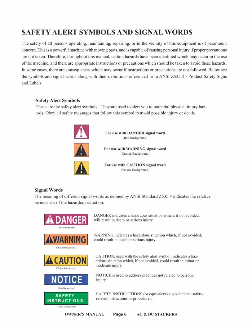
SAFETY ALERT SYMBOLS AND SIGNAL WORDSThe safety of all persons operating, maintaining, repairing, or in the vicinity of this equipment is of paramount concern. This is a powerful machine with moving parts, and is capable of causing personal injury if proper precautions are not taken. Therefore, throughout this manual, certain hazards have been identified which may occur in the use of the machine, and there are appropriate instructions or precautions which should be taken to avoid these hazards. In some cases, there are consequences which may occur if instructions or precautions are not followed. Below are the symbols and signal words along with their definitions referenced from ANSI Z535.4 - Product Safety Signs and Labels.
Safety Alert SymbolsThese are the safety alert symbols.. They are used to alert you to potential physical injury haz-ards. Obey all safety messages that follow this symbol to avoid possible injury or death.
For use with DANGER signal word(Red Background)
For use with WARNING signal word(Orange Background)
For use with CAUTION signal word(Yellow Background)
Signal WordsThe meaning of different signal words as defined by ANSI Standard Z535.4 indicates the relative seriousness of the hazardous situation.
DANGER indicates a hazardous situation which, if not avoided, will result in death or serious injury.
WARNING indicates a hazardous situation which, if not avoided, could result in death or serious injury.
CAUTION, used with the safety alert symbol, indicates a haz-ardous situation which, if not avoided, could result in minor or moderate injury.
NOTICE is used to address practices not related to personal injury.
(Red Background)
(Orange Background)
(Yellow Background)
(Blue Background)
SAFETYINSTRUCTIONS
SAFETY INSTRUCTIONS (or equivalent) signs indicate safety-related instructions or procedures.
(Green Background)
OWNER’S MANUAL Page 7 AC & DC STACKERS
S E C T I O N 2
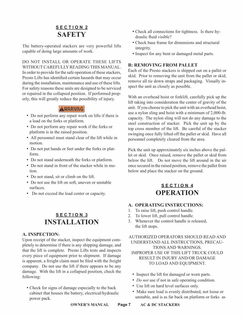
SAFETYThe battery-operated stackers are very powerful lifts capable of doing large amounts of work.
DO NOT INSTALL OR OPERATE THESE LIFTS WITHOUT CAREFULLY READING THIS MANUAL. In order to provide for the safe operation of these stackers, Presto Lifts has identified certain hazards that may occur during the installation, maintenance and use of these lifts. For safety reasons these units are designed to be serviced or repaired in the collapsed position. If performed prop-erly, this will greatly reduce the possibility of injury.
WARNING!• Do not perform any repair work on lifts if there is
a load on the forks or platform.• Do not perform any repair work if the forks or
platform is in the raised position.• All personnel must stand clear of the lift while in
motion.• Do not put hands or feet under the forks or plat-
form.• Do not stand underneath the forks or platform.• Do not stand in front of the stacker while in mo-
tion.• Do not stand, sit or climb on the lift.• Do not use the lift on soft, uneven or unstable
surfaces.• Do not exceed the load center or capacity.
S E C T I O N 3
INSTALLATIONA. INSPECTION:Upon receipt of the stacker, inspect the equipment com-pletely to determine if there is any shipping damage, and that the lift is complete. Presto Lifts tests and inspects every piece of equipment prior to shipment. If damage is apparent, a freight claim must be filed with the freight company. Do not use the lift if there appears to be any damage. With the lift in a collapsed position, check the following:
• Check for signs of damage especially to the back cabinet that houses the battery, electrical/hydraulic power pack.
• Check all connections for tightness. Is there hy-draulic fluid visible?
• Check base frame for dimensions and structural integrity.
• Inspect for any bent or damaged metal parts.
B: REMOVING FROM PALLETEach of the Presto stackers is shipped out on a pallet or skid. Prior to removing the unit from the pallet or skid, remove all tie down straps and packaging. Visually in-spect the unit as closely as possible.
With an overhead hoist or forklift, carefully pick up the lift taking into consideration the center of gravity of the unit. If you choose to pick the unit with an overhead hoist, use a nylon sling and hoist with a minimum of 2,000-lb. capacity. The nylon sling will not do any damage to the steel construction of stacker. Pick the unit up by the top cross member of the lift. Be careful of the stacker swinging once fully lifted off the pallet or skid. Have all personnel completely cleared from the area.
Pick the unit up approximately six inches above the pal-let or skid. Once raised, remove the pallet or skid from below the lift. Do not move the lift around in the air once secured in the raised position, remove the pallet from below and place the stacker on the ground.
S E C T I O N 4
OPERATIONA. OPERATING INSTRUCTIONS:1. To raise lift, push control handle.2. To lower lift, pull control handle.3. Whenever the control handle is released, the lift stops.
AUTHORIZED OPERATORS SHOULD READ AND UNDERSTAND ALL INSTRUCTIONS, PRECAU-
TIONS AND WARNINGS.IMPROPER USE OF THIS LIFT TRUCK COULD
RESULT IN INJURY AND/OR DAMAGETO LOAD AND EQUIPMENT.
• Inspect the lift for damaged or worn parts. •Donot use if not in safe operating condition.• Use lift on hard level surfaces only.• Make sure load is evenly distributed, not loose or
unstable, and is as far back on platform or forks as
OWNER’S MANUAL Page 8 AC & DC STACKERS
possible. Donotpick up loads on tips or forks or edge of platform.
• For fork models, adjust forks to the maximum practical width. Pick up loads on both forks.
• Donotoverload. Check load center and load weight capacities on manufacturer’s nameplate.
• Make sure travel and work area is clear of ob-structions.
• Check overhead clearance before lifting loads or transporting.
• Make sure floor lock pad is in firm contact with floor before lifting load, lowering load or using as a workstation.
• )Brace or block lift when sliding loads on or off platform or forks.
B. DAILY OPERATIONS MAINTENANCE CHECKS:1. Battery (If Equipped)
A. Check for corroded and loose terminals. A white powder substance will be present if there is any existing corrosion.
B. Visually inspect for any cracks or damage to the casing.
C. Check for loose battery tie-downs.
2. Charger (If Equipped)A. Inspect wire connections.B. Check power cord for nicks/damage.C. Check charger for proper mounting.
Hydraulic SystemD. Inspect pump and cylinder for oil leaks.E. Check hydraulic oil level.F. Check hydraulic fittings and hoses.G. Check ram for nicks/damage.H. Check fluid level. Unscrew plug or cap on
reservoir with the forks or platform in the lowered position. The fluid will be 1/2 to 3/4 of an inch from the opening.
3. Frame AssemblyA. Check floor lock.B. Check placement of safety screen.C. Check chain roller assembly connections.D. Check for any worn or damaged parts.
S E C T I O N 5
BATTERY MAINTENANCEA. PREPARING TO CHARGE A BATTERY
1. Always turn off E-stop and key switch before work-ing with the batteries.
2. Be sure the area around the stacker and the battery is well ventilated while battery is being charged.
3. The battery terminals, connections and wiring connections should be clean and free of corrosion. When cleaning any of these components wear a face shield or other suitable protective eyewear.
4. For a sealed battery (a battery without cell caps) carefully follow the manufacturer’s recharging instructions that are provided with the battery. If you do not have a copy of these instructions or the instructions for the battery charger they are avail-able free of charge by calling Presto @ 1-800-343-9322.
5. Read, understand and follow all battery and bat-terycharger manufacturer’s specific precautions while working with and/or charging batteries.
B. LOCATING THE CHARGER
1. Locate charger as far away from battery as the cables permit.
2. Do not operate charger in a closed area or restrict ventilation in any way.
C. PRECAUTIONS FOR GROUNDINGAND AC POWER CORD CONNECTION
Charger should be grounded to reduce risk of electric shock. Charger is equipped with an electric cord having an equipment-grounding conductor and grounding plug. The plug must be plugged into an outlet that is properly installed and grounded in ac-cordance with all local codes and ordinances.
DANGERNever alter the AC cord or plug provided. If itwill not fit outlet, have proper outlet installed by a qualified electrician. Improper connection can result in a risk of an electric shock.
OWNER’S MANUAL Page 9 AC & DC STACKERS
D. BATTERY CHARGER CONNECTIONPRECAUTIONS
CAUTIONConnect and disconnect the DC output plug (orclips) only when the AC cord is disconnected from the electric outlet. Never allow clips to touch each other.
1. To charge the unit, plug the charger into the 110 volt wall outlet. The charger is pre-wired to the battery.
2. Disconnect the charger from the 110 volt wall outlet once the indicators read fully charged.
S E C T I O N 6
MAINTENANCEOperation of Presto Hydraulic Lifts is very simple — as is their construction and require very little maintenance. Reasonable care will result in excellent trouble-free performance. Presto Hydraulic Lifts are designed for one-man operation and ease of performance.A. INSTRUCTIONS:
⇑ Grease wheels and casters at least once a month to maintain easy roll of lift.
⇑ Use only Hydraulic Oil (Conoco Super Hydraulic 32) in the hydraulic system. See hydraulic oil specifications table on page 25.
⇑ Donotoverload your lift.
B. MONTHLY OPERATIONS MAINTENANCE CHECKS:
1. BatteryA. Clean terminals.B. Clean battery compartment area.C. Check specific gravity — fully charged bat-
tery should read 1265. Using a hydrometer that measures specific gravity can check this.
2. Hydraulic System
A. Clean and inspect hydraulic cylinder.B. Lubricate chain with a rust inhibitive
lubricant. C. Check chain tension. The chain should be
tight enough so that it does not come off of the roller assembly.
3. Frame AssemblyA. Clean and lubricate all roller bearings and
cam followers.B. Clean and inspect all welds.C. Check wheels for wear and damage.D. Inspect nameplate for legibility. Place the
serial and model number shown on the name-plate on the cover of the manual for future reference.
4. Adjust Straddle Stacker LegsA. Secure the stacker with an overhead crane or
fork truck allowing the weight to be removed from the stacker legs.
B. Loosen the adjustment bolts and adjust both legs equally to the desired width.
C. Re-tighten the adjustment bolts.D. Test the stacker to ensure proper adjust-
ment.
All adjustments should be done by qualified person-nel. If in doubt, please contact your local dealer or Presto Lifts Customer Service Department at 800-343-9322.
OWNER’S MANUAL Page 10 AC & DC STACKERS
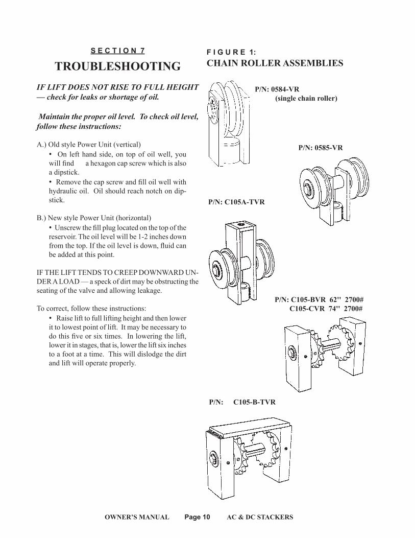
F I G U R E 1: CHAIN ROLLER ASSEMBLIES
P/N: C105-B-TVR
P/N: C105-BVR 62'' 2700# C105-CVR 74'' 2700#
P/N: C105A-TVR
P/N: 0584-VR (single chain roller)
P/N: 0585-VR
S E C T I O N 7
TROUBLESHOOTINGIF LIFT DOES NOT RISE TO FULL HEIGHT — check for leaks or shortage of oil.
Maintain the proper oil level. To check oil level, follow these instructions:
A.) Old style Power Unit (vertical)• On left hand side, on top of oil well, you will find a hexagon cap screw which is also a dipstick. • Remove the cap screw and fill oil well with hydraulic oil. Oil should reach notch on dip-stick.
B.) New style Power Unit (horizontal)• Unscrew the fill plug located on the top of the reservoir. The oil level will be 1-2 inches down from the top. If the oil level is down, fluid can be added at this point.
IF THE LIFT TENDS TO CREEP DOWNWARD UN-DER A LOAD — a speck of dirt may be obstructing the seating of the valve and allowing leakage.
To correct, follow these instructions:• Raise lift to full lifting height and then lower it to lowest point of lift. It may be necessary to do this five or six times. In lowering the lift, lower it in stages, that is, lower the lift six inches to a foot at a time. This will dislodge the dirt and lift will operate properly.
OWNER’S MANUAL Page 11 AC & DC STACKERS
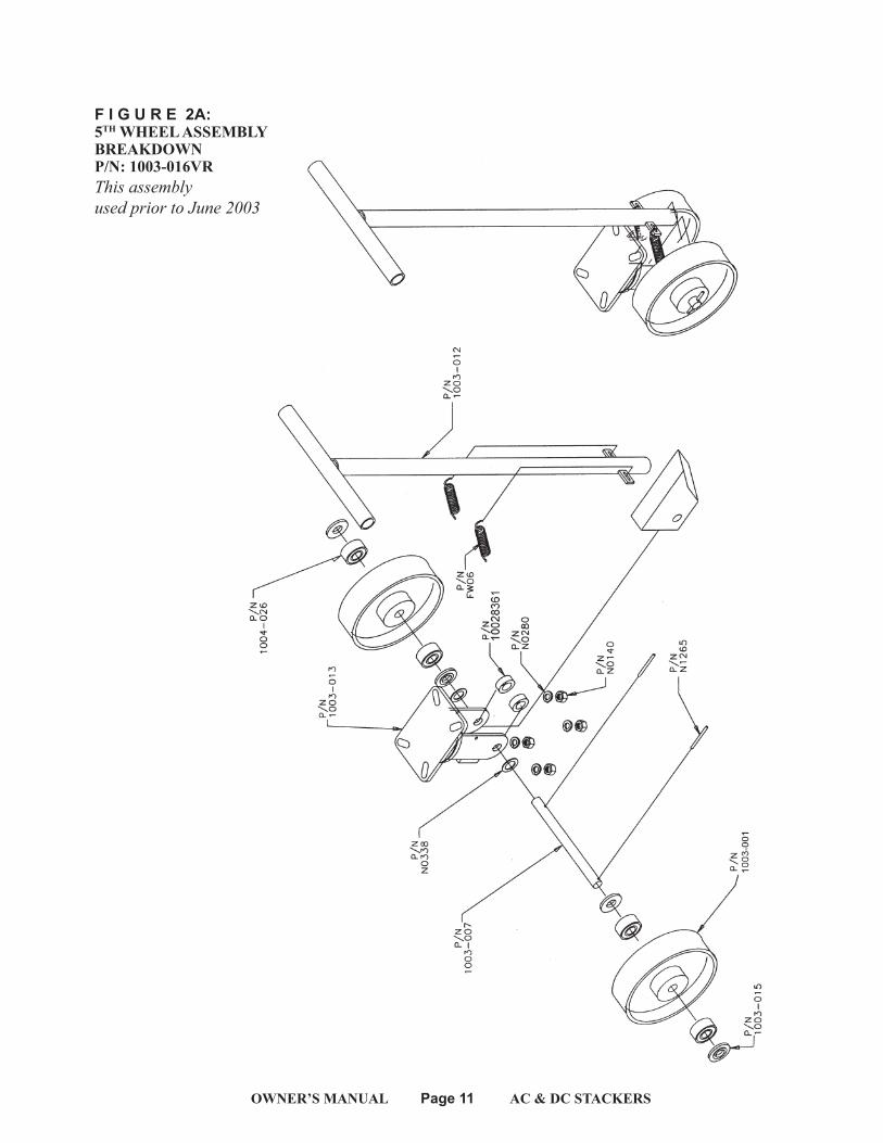
F I G U R E 2A: 5TH WHEEL ASSEMBLY BREAKDOWN P/N: 1003-016VRThisassemblyusedpriortoJune2003
OWNER’S MANUAL Page 12 AC & DC STACKERS
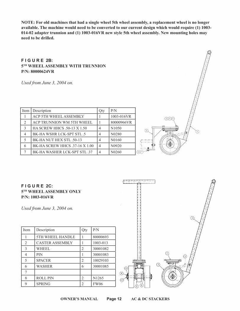
F I G U R E 2B: 5TH WHEEL ASSEMBLY WITH TRUNNIONP/N: 80000624VR
UsedfromJune3,2004on.
F I G U R E 2C: 5TH WHEEL ASSEMBLY ONLYP/N: 1003-016VR
UsedfromJune3,2004on.
Item Description Qty P/N
1 5TH WHEEL HANDLE 1 80000693 2 CASTER ASSEMBLY 1 1003-013 3 WHEEL 2 30001082 4 PIN 1 30001083 5 SPACER 2 10029103 6 WASHER 6 30001085 7 8 ROLL PIN 2 N1265 9 SPRING 2 FW06
Item Description Qty P/N 1 ACP 5TH WHEEL ASSEMBLY 1 1003-016VR 2 ACP TRUNNION WM 5TH WHEEL 1 80000966VR 3 HA SCREW HHCS .50-13 X 1.50 4 N1050 4 BK-HA WSHR LCK-SPT STL .5 4 N0280 5 BK-HA NUT HEX STL .50-13 4 N0160 6 BK-HA SCREW HHCS .37-16 X 1.00 4 N0920 7 BK-HA WASHER LCK-SPT STL .37 4 N0260
NOTE: For old machines that had a single wheel 5th wheel assembly, a replacement wheel is no longer available. The machine would need to be converted to our current design which would require (1) 1003-014-02 adapter trunnion and (1) 1003-016VR new style 5th wheel assembly. New mounting holes may need to be drilled.
OWNER’S MANUAL Page 13 AC & DC STACKERS
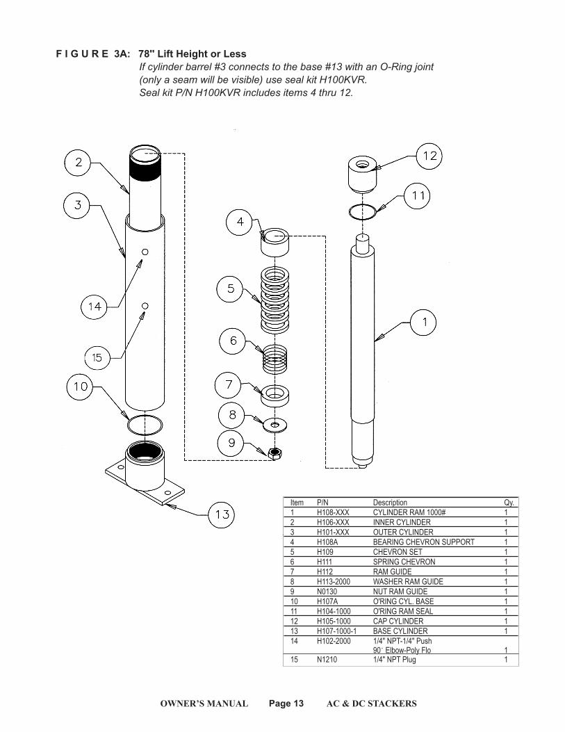
F I G U R E 3A: 78'' Lift Height or LessIf cylinder barrel #3 connects to the base #13 with an O-Ring joint (only a seam will be visible) use seal kit H100KVR.Seal kit P/N H100KVR includes items 4 thru 12.
Item P/N Description Qy.1 H108-XXX CYLINDER RAM 1000# 12 H106-XXX INNER CYLINDER 13 H101-XXX OUTER CYLINDER 14 H108A BEARING CHEVRON SUPPORT 15 H109 CHEVRON SET 16 H111 SPRING CHEVRON 17 H112 RAM GUIDE 18 H113-2000 WASHER RAM GUIDE 19 N0130 NUT RAM GUIDE 110 H107A O'RING CYL. BASE 111 H104-1000 O'RING RAM SEAL 112 H105-1000 CAP CYLINDER 113 H107-1000-1 BASE CYLINDER 114 H102-2000 1/4" NPT-1/4" Push 90 Elbow-Poly Flo 1 15 N1210 1/4" NPT Plug 1
OWNER’S MANUAL Page 14 AC & DC STACKERS
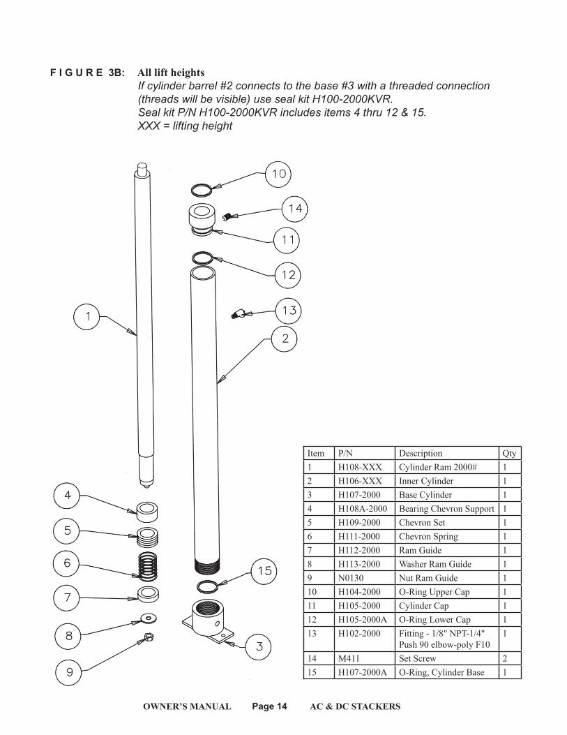
F I G U R E 3B: All lift heights If cylinder barrel #2 connects to the base #3 with a threaded connection (threads will be visible) use seal kit H100-2000KVR. Seal kit P/N H100-2000KVR includes items 4 thru 12 & 15. XXX = lifting height
Item P/N Description Qty1 H108-XXX Cylinder Ram 2000# 12 H106-XXX Inner Cylinder 13 H107-2000 Base Cylinder 14 H108A-2000 Bearing Chevron Support 15 H109-2000 Chevron Set 16 H111-2000 Chevron Spring 17 H112-2000 Ram Guide 18 H113-2000 Washer Ram Guide 19 N0130 Nut Ram Guide 110 H104-2000 O-Ring Upper Cap 111 H105-2000 Cylinder Cap 112 H105-2000A O-Ring Lower Cap 113 H102-2000 Fitting - 1/8" NPT-1/4"
Push 90 elbow-poly F101
14 M411 Set Screw 215 H107-2000A O-Ring, Cylinder Base 1
OWNER’S MANUAL Page 15 AC & DC STACKERS
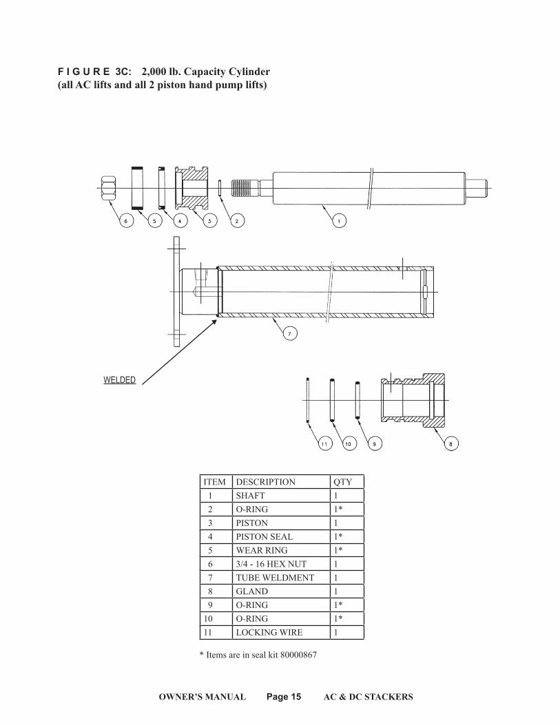
F I G U R E 3C: 2,000 lb. Capacity Cylinder(all AC lifts and all 2 piston hand pump lifts)
WELDED
ITEM DESCRIPTION QTY 1 SHAFT 1 2 O-RING 1* 3 PISTON 1 4 PISTON SEAL 1* 5 WEAR RING 1* 6 3/4 - 16 HEX NUT 1 7 TUBE WELDMENT 1 8 GLAND 1 9 O-RING 1*10 O-RING 1*11 LOCKING WIRE 1
* Items are in seal kit 80000867
OWNER’S MANUAL Page 16 AC & DC STACKERS
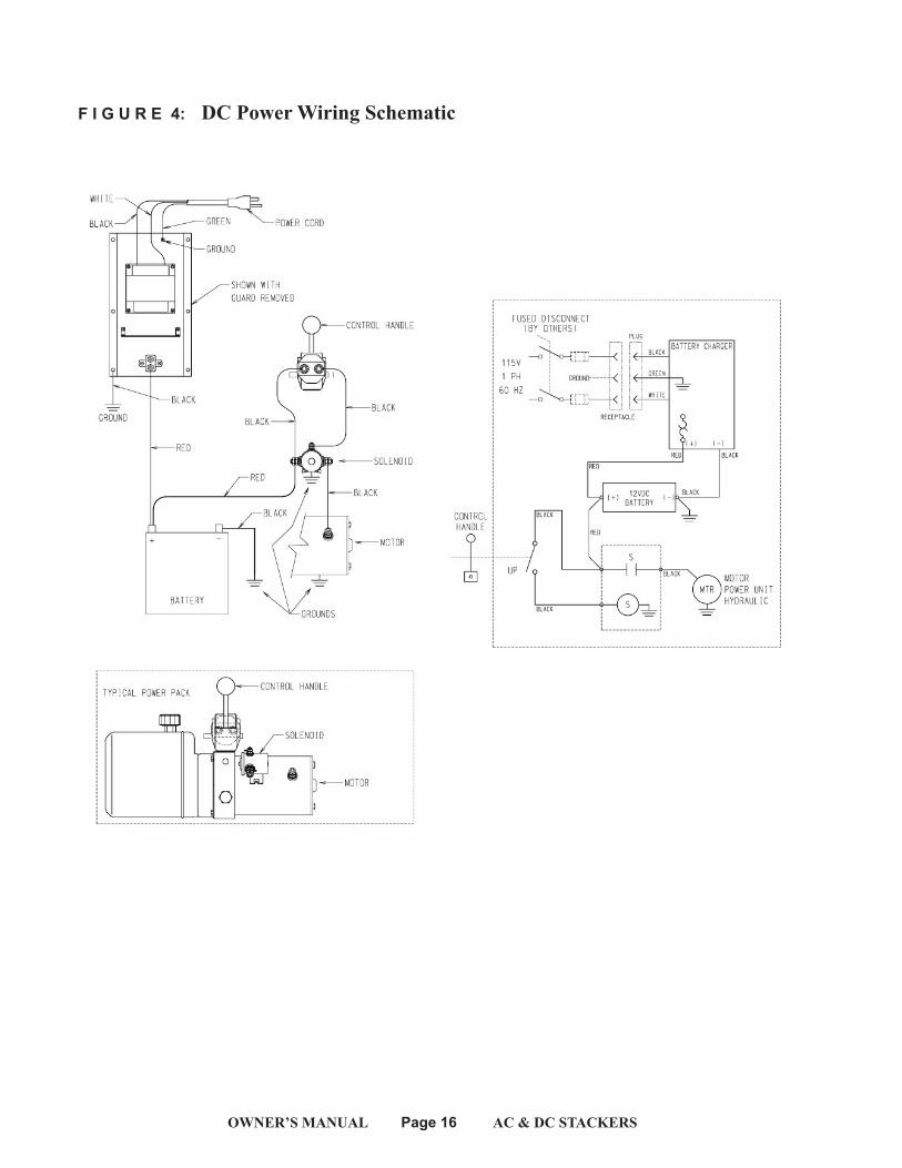
F I G U R E 4: DC Power Wiring Schematic
OWNER’S MANUAL Page 17 AC & DC STACKERS
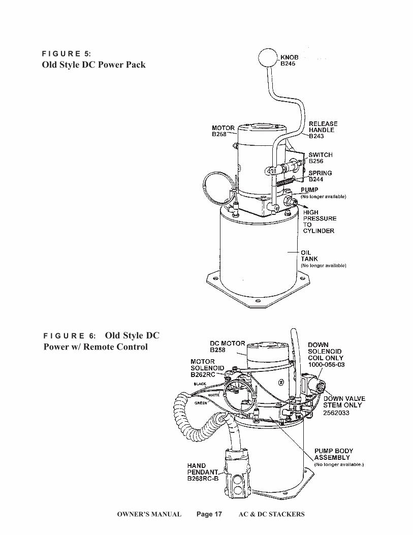
F I G U R E 5: Old Style DC Power Pack
F I G U R E 6: Old Style DC Power w/ Remote Control
OWNER’S MANUAL Page 18 AC & DC STACKERS
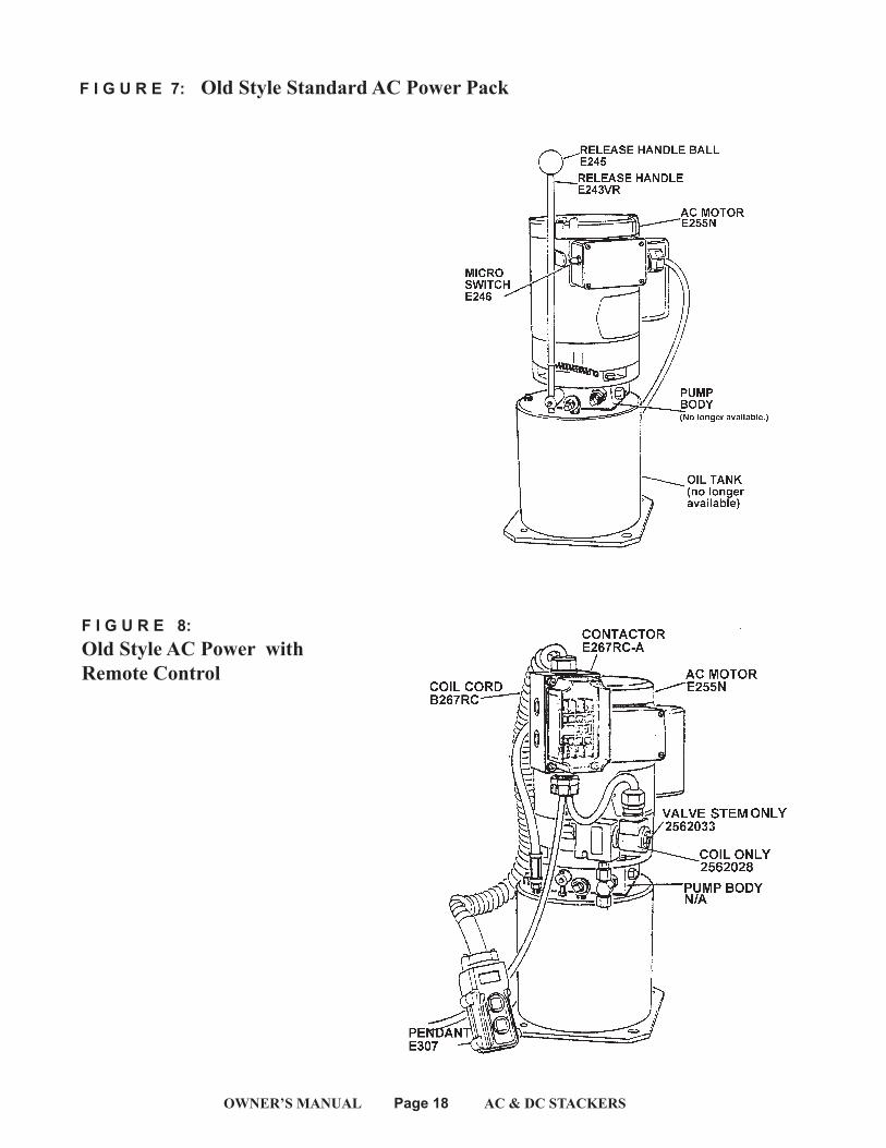
F I G U R E 8: Old Style AC Power withRemote Control
F I G U R E 7: Old Style Standard AC Power Pack
OWNER’S MANUAL Page 19 AC & DC STACKERS
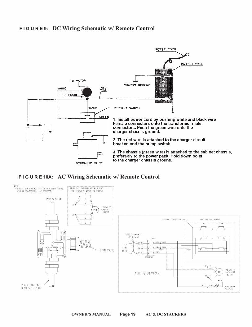
F I G U R E 9: DC Wiring Schematic w/ Remote Control
F I G U R E 10A: AC Wiring Schematic w/ Remote Control
OWNER’S MANUAL Page 20 AC & DC STACKERS
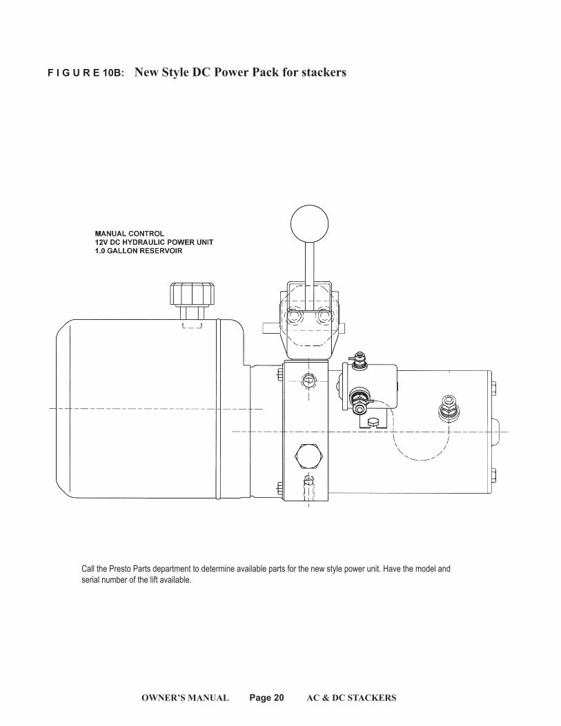
F I G U R E 10B: New Style DC Power Pack for stackers
Call the Presto Parts department to determine available parts for the new style power unit. Have the model and serial number of the lift available.
OWNER’S MANUAL Page 21 AC & DC STACKERS
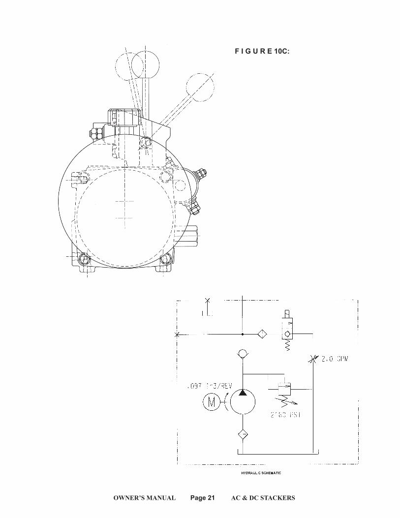
F I G U R E 10C:
OWNER’S MANUAL Page 22 AC & DC STACKERS
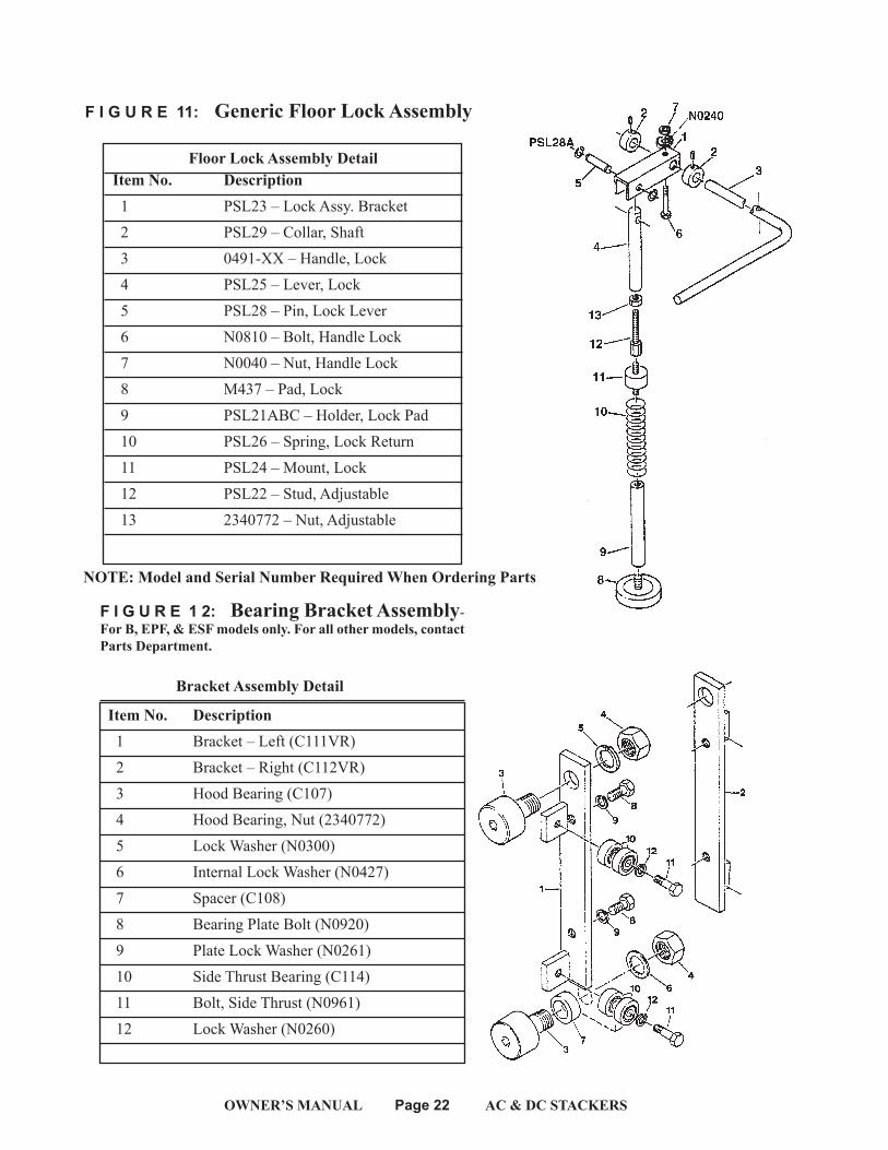
Floor Lock Assembly Detail Item No. Description 1 PSL23 – Lock Assy. Bracket 2 PSL29 – Collar, Shaft 3 0491-XX – Handle, Lock 4 PSL25 – Lever, Lock 5 PSL28 – Pin, Lock Lever 6 N0810 – Bolt, Handle Lock 7 N0040 – Nut, Handle Lock 8 M437 – Pad, Lock 9 PSL21ABC – Holder, Lock Pad 10 PSL26 – Spring, Lock Return 11 PSL24 – Mount, Lock 12 PSL22 – Stud, Adjustable 13 2340772 – Nut, Adjustable
F I G U R E 1 2: Bearing Bracket Assembly-For B, EPF, & ESF models only. For all other models, contact Parts Department.
Bracket Assembly Detail
Item No. Description 1 Bracket – Left (C111VR) 2 Bracket – Right (C112VR) 3 Hood Bearing (C107) 4 Hood Bearing, Nut (2340772) 5 Lock Washer (N0300) 6 Internal Lock Washer (N0427) 7 Spacer (C108) 8 Bearing Plate Bolt (N0920) 9 Plate Lock Washer (N0261) 10 Side Thrust Bearing (C114) 11 Bolt, Side Thrust (N0961) 12 Lock Washer (N0260)
F I G U R E 11: Generic Floor Lock Assembly
NOTE: Model and Serial Number Required When Ordering Parts
OWNER’S MANUAL Page 23 AC & DC STACKERS
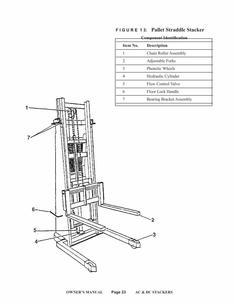
F I G U R E 1 3: Pallet Straddle Stacker Component Identification
Item No. Description
1 Chain Roller Assembly
2 Adjustable Forks
3 Phenolic Wheels
4 Hydraulic Cylinder
5 Flow Control Valve
6 Floor Lock Handle
7 Bearing Bracket Assembly
OWNER’S MANUAL Page 24 AC & DC STACKERS
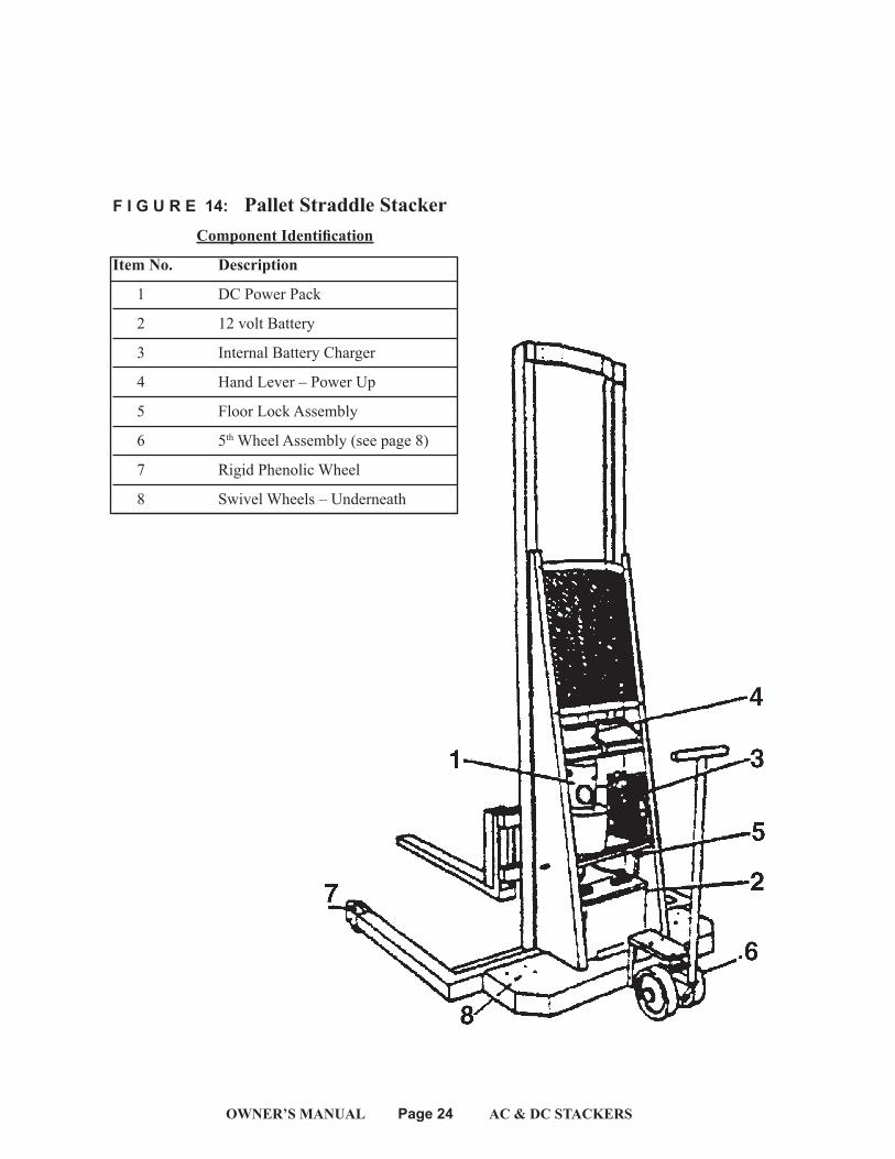
F I G U R E 14: Pallet Straddle Stacker Component Identification
Item No. Description
1 DC Power Pack
2 12 volt Battery
3 Internal Battery Charger
4 Hand Lever – Power Up
5 Floor Lock Assembly
6 5th Wheel Assembly (see page 8)
7 Rigid Phenolic Wheel
8 Swivel Wheels – Underneath
OWNER’S MANUAL Page 25 AC & DC STACKERS
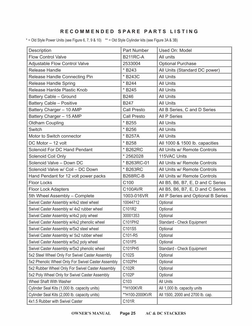
* = Old Style Power Units (see Figure 6, 7, 9 & 10) ** = Old Style Ciylinder kits (see Figure 3A & 3B)
R E C O M M E N D E D S P A R E P A R T S L I S T I N G
Description Part Number Used On: ModelFlow Control Valve B211RC-A All unitsAdjustable Flow Control Valve 2533004 Optional PurchaseRelease Handle * B243 All Units (Standard DC power)Release Handle Connecting Pin * B243C All UnitsRelease Handle Spring * B244 All UnitsRelease Hanlde Plastic Knob * B245 All UnitsBattery Cable – Ground B246 All UnitsBattery Cable – Positive B247 All UnitsBattery Charger – 10 AMP Call Presto All B Series, C and D SeriesBattery Charger – 15 AMP Call Presto All P Series Oldham Coupling * B255 All Units Switch * B256 All UnitsMotor to Switch connector * B257A All UnitsDC Motor – 12 volt * B258 All 1000 & 1500 lb. capacitiesSolenoid For DC Hand Pendant * B262RC All Units w/ Remote ControlsSolenoid Coil Only * 2562028 115VAC UnitsSolenoid Valve – Down DC * B263RC-01 All Units w/ Remote ControlsSolenoid Valve w/ Coil – DC Down * B263RC All Units w/ Remote ControlsHand Pendant for 12 volt power packs B268RC-B All Units w/ Remote ControlsFloor Locks C100 All B5, B6, B7, E, D and C SeriesFloor Lock Adapters C100AVR All B5, B6, B7, E, D and C Series5th Wheel Assembly – Complete 1003-016VR All P Series and Optional B SeriesSwivel Caster Assembly w/4x2 steel wheel 10044712 OptionalSwivel Caster Assembly w/ 4x2 rubber wheel C101R2 OptionalSwivel Caster Assembly w/4x2 poly wheel 30001353 OptionalSwivel Caster Assembly w/4x2 phenolic wheel C101PH2 Standard - Check EquipmentSwivel Caster Assembly w/5x2 steel wheel C101S5 OptionalSwivel Caster Assembly w/ 5x2 rubber wheel C101-R5 OptionalSwivel Caster Assembly w/5x2 poly wheel C101P5 OptionalSwivel Caster Assembly w/5x2 phenolic wheel C101PH5 Standard - Check Equipment5x2 Steel Wheel Only For Swivel Caster Assembly C102S Optional5x2 Phenolic Wheel Only For Swivel Caster Assembly C102PH Optional5x2 Rubber Wheel Only For Swivel Caster Assembly C102R Optional5x2 Poly Wheel Only for Swivel Caster Assembly C102P OptionalWheel Shaft With Washer C103 All UnitsCylinder Seal Kits (1,000 lb. capacity units) **H100KVR All 1,000 lb. capacity unitsCylinder Seal Kits (2,000 lb. capacity units) **H100-2000KVR All 1500, 2000 and 2700 lb. cap.4x1.5 Rubber with Swivel Caster C101R
OWNER’S MANUAL Page 26 AC & DC STACKERSOWNER’S MANUAL Page 26 AC & DC STACKERS
2
LOC
ATE
ITEM
NO
. C17
2 C
ENTE
RED
ON
PLA
TFO
RM B
AC
KPLA
TE A
S SH
OW
N
7 LOC
ATE
ITEM
NO
. 300
0041
4 O
NSI
DE
OF
MA
ST A
S SH
OW
N
5
LOC
ATE
ITEM
NO
. 100
6435
8 O
NSI
DE
OF
MA
ST A
S SH
OW
N
6
LOC
ATE
ITEM
NO
. 100
6435
9 O
NSI
DE
OF
MA
ST A
S SH
OW
N
4
LOC
ATE
ITEM
NO
. 100
6435
6 O
NSI
DE
OF
MA
ST A
S SH
OW
N
8
IMPO
RTA
NT:
1002
1381
IS T
O B
E A
PPLIE
D T
O11
5/1/
60 P
OW
ER M
AC
HIN
ES O
NLY
. LO
CA
TETA
G O
N P
OW
ER C
ORD
1" A
WA
Y FR
OM
PLU
G
1
LOC
ATE
ITEM
NO
. C15
7 O
NC
YLIN
DER
BA
RREL
AS
SHO
WN
3
LOC
ATE
ITEM
NO
. C19
7 C
ENTE
RED
ON
CA
STER
MO
UNT
PLA
TE A
S SH
OW
N
NO
TE: S
ERIA
L LA
BELS
ARE
PRI
NTE
D T
O E
AC
H JO
B O
RDER
. LO
CA
TE IN
TW
O P
LAC
ES (O
NE
ON
BA
SE A
ND
ON
E O
N U
ND
ERSI
DE
OF
PLA
TFO
RM)
IMPO
RTA
NT:
IF Y
OU
HAV
E A
NY
QUE
STIO
NS
PLEA
SE C
ON
TAC
T O
URC
USTO
MER
SER
VIC
E D
EPA
RTM
ENT
AT
1-80
0-34
3-93
22
1. T
HE A
REA
WHE
RE T
HE N
EW R
EPLA
CEM
ENT
LABE
LING
WILL
BE
APP
LIED
SHO
ULD
BE
FREE
OF
ALL
DIR
T, G
REA
SE A
ND
GRI
ME.
2. T
HE P
AIN
TED
SUR
FAC
E SH
OUL
D B
E SM
OO
TH A
ND
FRE
E O
F A
NY
RUST
. IF
RUST
ED, S
AN
D S
MO
OTH
, CLE
AN
AN
D R
EPA
INT
B
EFO
RE A
TTEM
PTIN
G T
O A
FFIX
NEW
LA
BELS
.
3. P
EEL
OFF
BA
CKI
NG
AN
D A
PPLY
LA
BEL
USIN
G C
ARE
TO
REM
OV
E A
IR B
UBBL
ES A
S YO
U A
PPLY
THE
LA
BEL.
4. P
RESS
LA
BEL
DO
WN
FIR
MLY
WITH
A S
QUE
EGEE
OR
ROLL
ER.
THIS
EQ
UIPM
ENT
IS B
UILT
IN A
CC
ORD
AN
CE
WITH
AN
SI M
H29.
THA
T ST
AN
DA
RD,
AM
ON
G O
THER
THI
NG
S, D
EFIN
ES T
HE E
ND
USE
R'S
RESP
ON
SIBI
LITY
TO M
AIN
TAIN
THE
EQ
UIPM
ENT
WHI
CH
IN
CLU
DES
SEE
ING
THA
T A
LL N
AM
E PL
ATE
S, P
REC
AUT
ION
ARY
AN
D IN
STRU
CTA
L M
ARK
ING
S, A
ND
/OR
LABE
LING
IS IN
PLA
CE
AN
D L
EGIB
LE. P
LEA
SE F
OLL
OW
THE
INST
RUC
TION
S BE
LOW
TO
AFF
IX N
EW L
ABE
LING
TO
THE
EQ
UIPM
ENT.
THIS
LA
BEL
LO
CA
TION
DRA
WIN
GA
PPLIE
S TO
ALL
OF
THE
MA
CHI
NES
LISTE
D B
ELO
W:
ESF
SERI
ES EP
F SE
RIES
EPFT
SER
IES
ITEM
N
O.
QTY
.U/
MD
ESC
RIPT
ION
PART
NO
.
81
EABK
-LD
DC
L 2.
50X1
2.75
(EN
GLIS
H A
ND
SPA
NIS
1002
1381
71
EABK
-LD
DC
L 3.
00 H
ELP
LINE
3000
0414
61
EABK
-LD
DC
L 3.
00X4
.00
OPE
RATIN
G IN
STRU
CTIO
1006
4359
51
EABK
-LD
DC
L 3.
00X5
.00
IMPR
OPE
R US
E O
F LIF
T10
0643
584
1EA
BK-L
D D
CL
3.00
X5.0
0 N
OTIC
E O
VER
LOA
DIN
G W
1006
4356
31
EABK
-LD
DC
L 8.
00X1
.50
LOC
K UP
. .
LOC
K D
OC
197
21
EALD
2.5
0 15
" LO
AD
CEN
TER
C17
21
1EA
BK-L
D D
CL
3.75
X7.7
5 D
O N
OT
STA
ND
ON
FO
RKC
157
REV
ISIO
NS
REV
.
D
ESC
RIPT
ION
DA
TERE
VIS
ED B
YEC
O #
12
ABCD
ABD C
2SH
EET 1
OF
1D
WG
NO
3 3
4 4
5 5
6 6
7 7
8 8
STATUS:CAD Area WIP
3RD
AN
GLE
PRO
JEC
TION
16
LB
REV
DW
G.
NO
.D SI
ZETIT
LE:
FRA
CTIO
NS
1
/.X
XX
.005
.XX
.01
AN
GLE
S:
.5
USE
OF
PRO
PRIE
TARY
INFO
RMA
TION
LIM
ITED
TO W
RITT
EN A
GRE
EMEN
T
SCA
LEW
TRE
FERE
NC
EC
AG
E C
OD
E06
3Z8
UNLE
SS O
THER
WIS
ESP
ECIF
IED
.D
IMEN
SIO
NS
ARE
ININ
CHE
S
SHEE
T 1 O
F 1
DR
CK
1:1
2
09/0
3/15
DA
TE
DA
TE
CFM
MO
DEL
PRO
JEC
T:
v.14
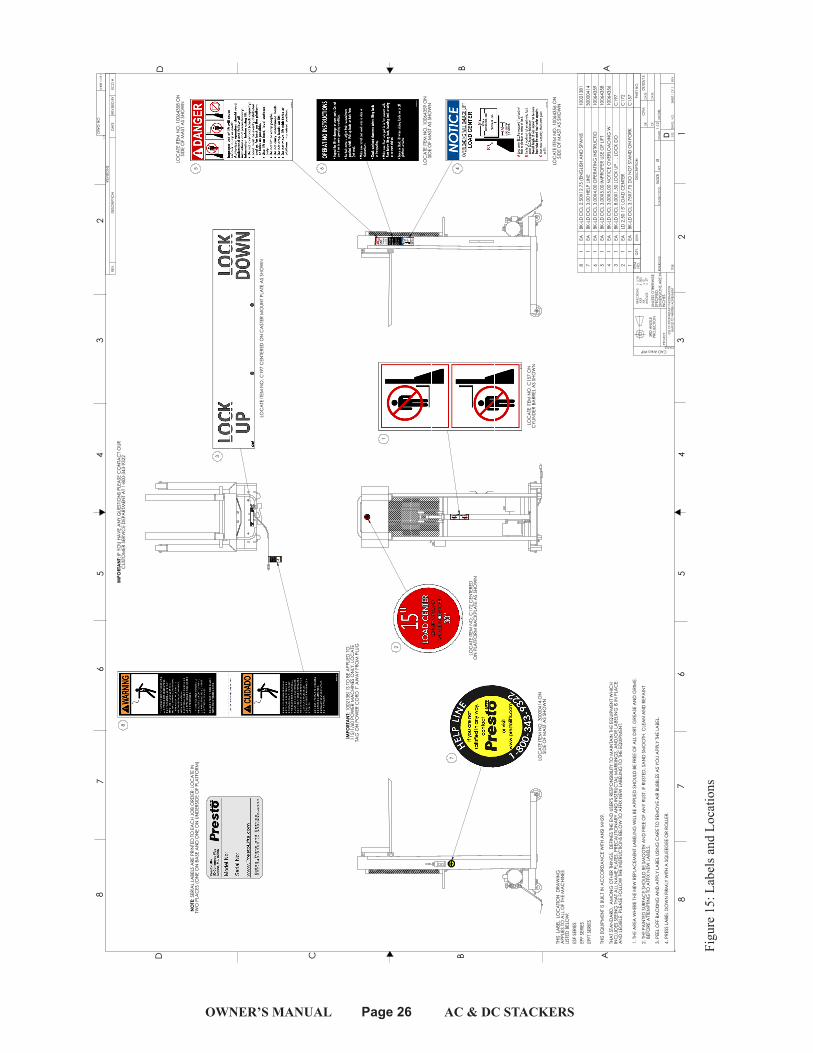
Figu
re 1
5: L
abel
s and
Loc
atio
ns
Figu
re 1
5: L
abel
s and
Loc
atio
ns
OWNER’S MANUAL Page 27 AC & DC STACKERS
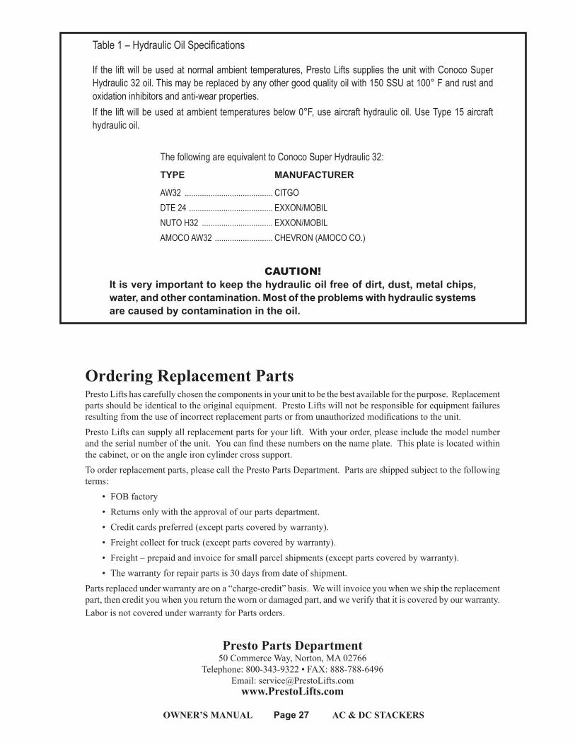
Table 1 – Hydraulic Oil Specifications
If the lift will be used at normal ambient temperatures, Presto Lifts supplies the unit with Conoco Super Hydraulic 32 oil. This may be replaced by any other good quality oil with 150 SSU at 100° F and rust and oxidation inhibitors and anti-wear properties. If the lift will be used at ambient temperatures below 0°F, use aircraft hydraulic oil. Use Type 15 aircraft hydraulic oil.
The following are equivalent to Conoco Super Hydraulic 32: TYPE MANUFACTURER
AW32 ......................................... CITGO DTE 24 ....................................... EXXON/MOBILNUTO H32 ................................. EXXON/MOBILAMOCO AW32 ........................... CHEVRON (AMOCO CO.)
CAUTION! It is very important to keep the hydraulic oil free of dirt, dust, metal chips, water, and other contamination. Most of the problems with hydraulic systems are caused by contamination in the oil.
Ordering Replacement PartsPresto Lifts has carefully chosen the components in your unit to be the best available for the purpose. Replacement parts should be identical to the original equipment. Presto Lifts will not be responsible for equipment failures resulting from the use of incorrect replacement parts or from unauthorized modifications to the unit. Presto Lifts can supply all replacement parts for your lift. With your order, please include the model number and the serial number of the unit. You can find these numbers on the name plate. This plate is located within the cabinet, or on the angle iron cylinder cross support.To order replacement parts, please call the Presto Parts Department. Parts are shipped subject to the following terms:
• FOB factory• Returns only with the approval of our parts department.• Credit cards preferred (except parts covered by warranty).• Freight collect for truck (except parts covered by warranty).• Freight – prepaid and invoice for small parcel shipments (except parts covered by warranty).• The warranty for repair parts is 30 days from date of shipment.
Parts replaced under warranty are on a “charge-credit” basis. We will invoice you when we ship the replacement part, then credit you when you return the worn or damaged part, and we verify that it is covered by our warranty. Labor is not covered under warranty for Parts orders.
Presto Parts Department50 Commerce Way, Norton, MA 02766
Telephone: 800-343-9322 • FAX: 888-788-6496Email: [email protected]
www.PrestoLifts.com
OWNER’S MANUAL Page 28 AC & DC STACKERS
PARTSStandard parts may be returned with a 20% restocking fee or $35.00 net, whichever is greater. Modified or custom-engineered parts are not returnable. Unfortunately, due to potentially concealed damage, all sales of electrical assemblies are final.
QUALITY ISSUESShould you feel there is a quality problem, please contact the seller to ask questions and gather information on how to rectify the issue. Presto Lift Inc. reserves the right to determine potential credits, as a result of factory defects, based on its inspection of the merchandise.
GENERALAll products shipped from our factory have passed Quality Assurance inspection and testing. The carrier of choice has signed for, and accepted the product in new working condition. The customer should inspect to ensure it is not received damaged, has no concealed damage or is not incomplete. Parts orders are determined to be complete based upon Presto Lift, Inc. inspection sheets and carrier shipping weights.
OWNER’S MANUAL Page 29 AC & DC STACKERS
RETURN MATERIALS AUTHORIZATION POLICY
Presto Lifts provides the Return Materials Authorization (RMA) Policy, for specific models, as a courtesy to our distributors in the event they do not receive what they ordered. If a customer wishes to return a Presto Lifts product, please contact the Customer Service Department and request an RMA number. This request must be made on or before the fifteenth calendar day following the date of Presto Lifts’ invoice for the merchandise. Not all units are returnable. Quantity orders and special designs cannot be returned under any circumstances. Presto Customer Service reserves the right for final judgment on all product returns.
The RMA number must appear on the outside of any packaging material for a return to be accepted and processed by Presto Lifts. Customers shipping returns from the Continental US, Canada, or Mexico have thirty (30) days from date of RMA issue to have the product arrive at Presto Lifts’ facility. All merchandise must arrive Free on Board at Presto Lifts’ facility or the shipment will be refused and returned to the sender. All credits are issued less restocking and refurbishing charges, regardless if the merchandise was damaged in transit.
Return addresses: please refer to your RMA for the address to which your product should be returned.
Presto Lift Inc.715 Highway 77
Manila, Arkansas 72442
Telephone: 800-343-9322Fax: 888-788-6496
OWNER’S MANUAL Page 30 AC & DC STACKERS
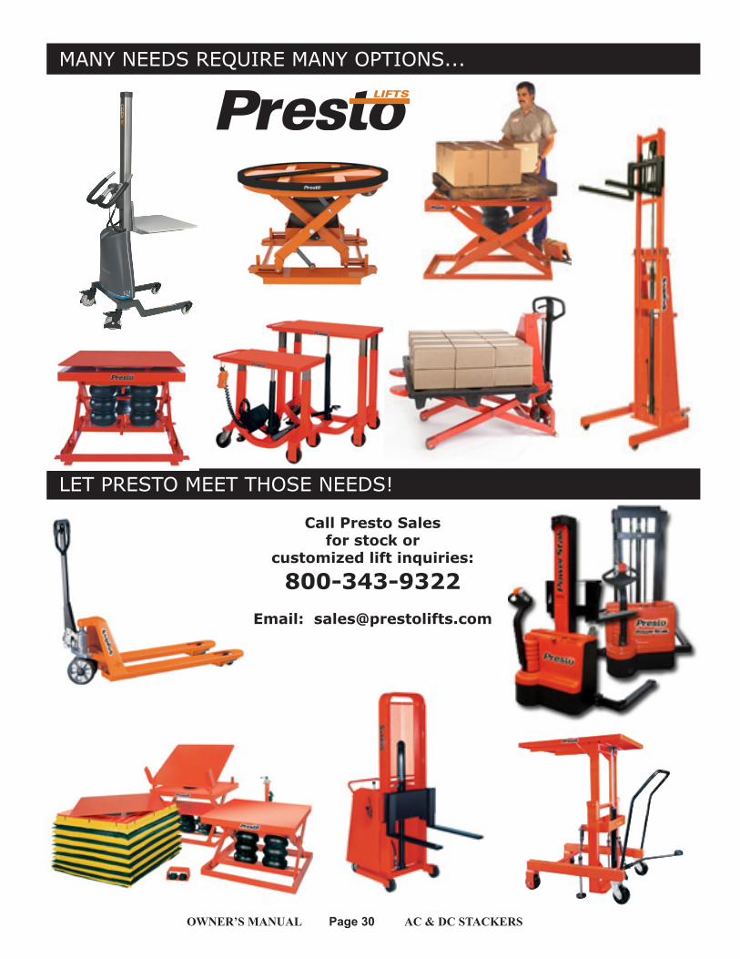
LET PRESTO MEET THOSE NEEDS!
MANY NEEDS REQUIRE MANY OPTIONS...
Call Presto Sales for stock or
customized lift inquiries:
800-343-9322Email: [email protected]