AC Corrosion and Mitigation - Kansas Corporation … Corrosion and Mitigation Mike Ames Director...
68
AC Corrosion and Mitigation Mike Ames Director Technical Operations Chapman Engineering Oct 20/21, 2015 KCC Pipeline Safety Seminar Manhattan, KS
Transcript of AC Corrosion and Mitigation - Kansas Corporation … Corrosion and Mitigation Mike Ames Director...
AC Corrosion and Mitigation
Mike Ames Director Technical Operations
Chapman Engineering Oct 20/21, 2015
KCC Pipeline Safety Seminar Manhattan, KS
NACE SP0177-2007
• The initial publication of the standard, which is titled “Mitigation of Alternating Current and Lightning Effects on Metallic Structures and Corrosion Control Systems” was July 1977
• The safety concerns of AC on pipelines was established in 1947, which is now accepted as keeping AC potentials below 15 volts for safety
• Beginning in the mid 1990’s, concerns for AC corrosion mitigation began when it was identified as a cause of corrosion in Germany and Australia
Chapman Engineering 2
What Has Caused this Now?
• The implementation of pipelines in electrical power line right of ways is not new.
• Implementing of new high dielectric coatings is new, and new constructions began using coatings like FBE in the mid 1970’s, but most were in open country locations, with a small percentage in common corridors with AC lines
• Beginning in the 1980’s the cost of new ROW for pipelines, separated from other lines and utilities was seen as too costly, and most new lines were installed with FBE in common corridors with AC Power lines
• Common corridors were considered a good use of expensive ROW and less of an impact on congested areas as well. So the practice has expanded over the years.
Chapman Engineering 3
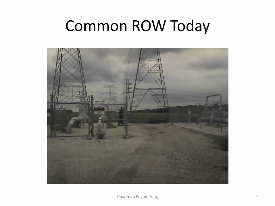
Common ROW Today
Chapman Engineering 4
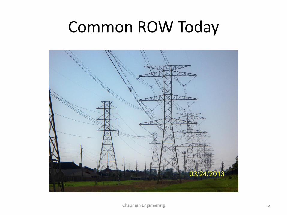
Common ROW Today
Chapman Engineering 5
General Perspective
• The consequence of well insulated pipelines in High Voltage AC corridors resulted in pipelines suffering high current loads of AC as a byproduct of inductive, capacitive, and direct coupling issues with the power lines.
• The pipeline basically is now a secondary winding of a gigantic transformer, with the AC power line as the primary winding.
• Voltages induced into the pipeline go in the opposite direction to those in the power line.
• These voltages can build to levels that can become safety hazards, and the current values of the pipe line can result in corrosion to the pipe walls by AC Corrosion
• AC Corrosion is not yet a clearly defined process, however, it does have some characteristic indications that are commonly associated with it from field inspections.
Chapman Engineering 6
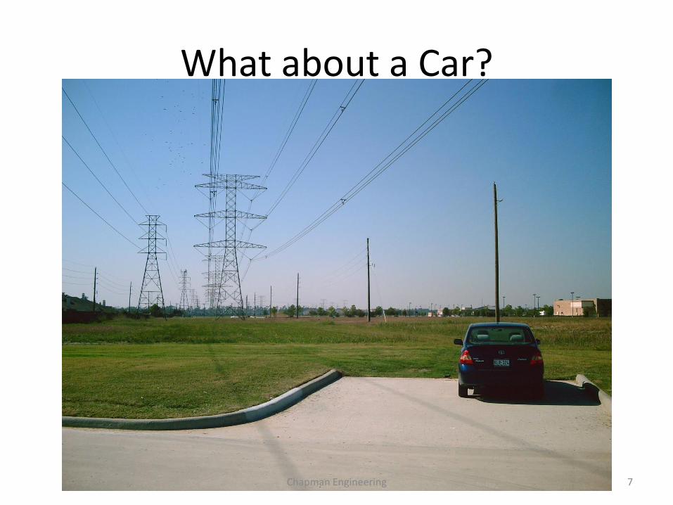
What about a Car?
Chapman Engineering 7
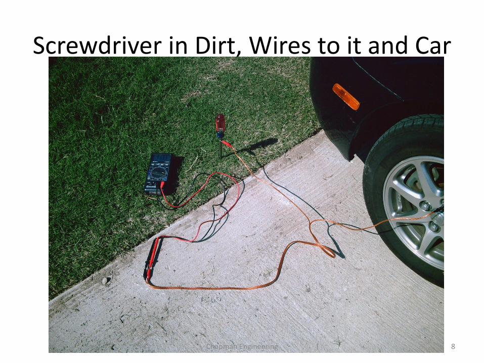
Screwdriver in Dirt, Wires to it and Car
Chapman Engineering 8
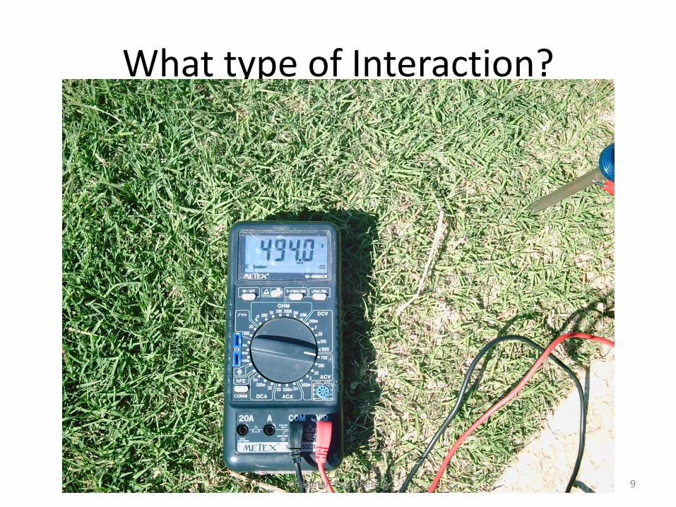
What type of Interaction?
Chapman Engineering 9
Types of AC Power Line/Pipeline Involvement
• Inductive Coupling The process is one where the nearby
pipeline and parallel power line orientation induces magnetic fields in the pipeline, opposite to those in the power line.
The model is a power transformer, with the power line the primary winding, the pipeline as the secondary winding, and the air and earth as the core
This process primarily causes the flow of high current levels in the pipeline, that may need to be returned to the power line to protect the pipeline.
• Capacitive Coupling This process creates charges on the
pipeline as the opposite plate of a leaky capacitor and the power line as the other capacitor.
Normally the current accompanying this coupling is low except during construction where the isolation of the pipeline can be much better than the buried pipeline, which allows the pipeline to charge to a high voltage, engendering shock hazards, and sufficient current to cause damage to people and equipment.
Auxiliary grounding is recommended for this situation during construction.
Normally when buried there is much less capacitive coupling.
Chapman Engineering 10
Pipeline/Power Line Interaction
• Resistive Coupling/Faults A rare condition normally associated
with a short from the power line to the ground, or to the pipeline directly.
The coupling can happen from a power line contacting a tree, a bad insulator allowing contact between the tower and a phase line, a line falling to equipment in the area or to ground.
The currents coupled to the pipeline can be very large, and normally of short duration as switchgear is oriented to disconnect lines that have this situation.
The major issue of this type of coupling may be significant coating damage from the high voltages and currents involved
• Power Arc, and Lightning Power arcs can happen during fault
currents, where the soil is ionized to allow an arc to the pipeline or soil near the pipeline. Lightning can be similar but is normally of less an issue on coating damage than arcs and faults may be.
Lightning can ionize the soil and penetrate to the pipeline, even to the point of burning holes in the pipe wall. Normally this would be in an area of higher soil resistivity with an area of less cover over the line. Lightning can also cause coating damage, but may be less of an area of damage than an arc or fault.
Chapman Engineering 11
HVAC/Pipeline Interactions
Chapman Engineering 12
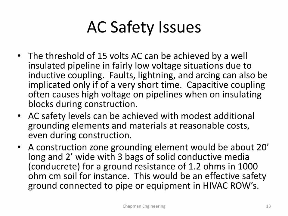
AC Safety Issues
• The threshold of 15 volts AC can be achieved by a well insulated pipeline in fairly low voltage situations due to inductive coupling. Faults, lightning, and arcing can also be implicated only if of a very short time. Capacitive coupling often causes high voltage on pipelines when on insulating blocks during construction.
• AC safety levels can be achieved with modest additional grounding elements and materials at reasonable costs, even during construction.
• A construction zone grounding element would be about 20’ long and 2’ wide with 3 bags of solid conductive media (conducrete) for a ground resistance of 1.2 ohms in 1000 ohm cm soil for instance. This would be an effective safety ground connected to pipe or equipment in HIVAC ROW’s.
Chapman Engineering 13
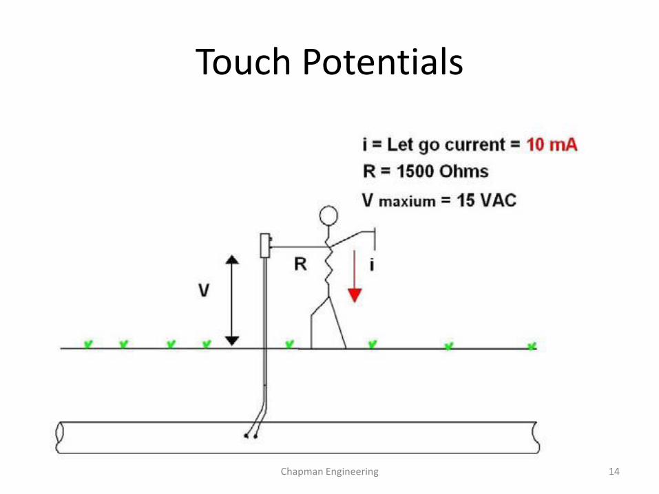
Touch Potentials
Chapman Engineering 14
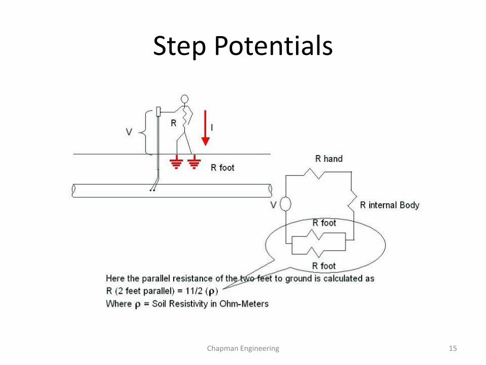
Step Potentials
Chapman Engineering 15
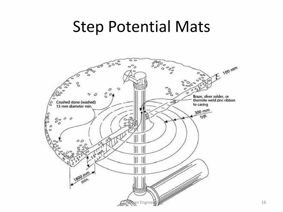
Step Potential Mats
Chapman Engineering 16
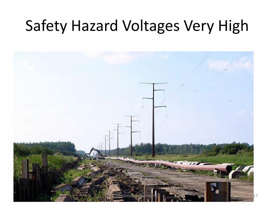
Safety Hazard Voltages Very High
Chapman Engineering 17
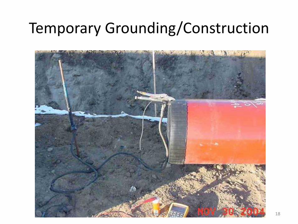
Temporary Grounding/Construction
Chapman Engineering 18
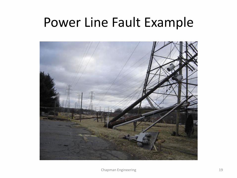
Power Line Fault Example
Chapman Engineering 19
AC Corrosion Characteristics
• AC corrosion is possible mainly due to inductive coupling which applies the higher current values to the line for long distances.
• Where the induced AC finds an opportunity to leave the pipe, through an opening in the coating to the soil, low soil resistivity usually is needed to have AC corrosion.
• The main culprit is the AC Current Density. • The lower the soil resistivity and the smaller the
coating anomaly, the higher current density and the higher the probability of corrosion issues.
Chapman Engineering 20
What is Meant by AC Current Density?
• The current density level is important, not necessarily in the pipeline itself, but at the point of discharge from the pipeline into the soil.
• Reported data from field inspections have shown a range of AC current densities of 0 to 20A/m2 are not involved with AC corrosion. From 20A/m2 to 100A/m2 there may be an involvement, while levels over 100A/m2 are strongly indicated to have AC corrosion active.
Chapman Engineering 21
What affects the AC Current Density?
• High soil resistivities are an enhancement to protect the pipeline by lowering the current density.
• Low soil resistivities allow higher current densities as the current flow away from the coating anomaly is enhanced.
• The size of the defect is critically important. Densities of current from a scrape of several inches in length will have lower current densities. While a small defect in the coating, such as made by a grain of sand in the coating will have much higher current densities as the current is being pushed from a much smaller cross sectional area.
Chapman Engineering 22
Further AC Current Density
• The availability of the current in the pipeline is also a major factor. If the pipeline is in a corridor with low AC current power lines, the critical current densities may be too low induced in the pipeline to be an issue, while large tower like lines with high voltages may indeed be involved with it. Each case is different, which points strongly to the need of field measurements and accurate modeling.
• Normally a length of pipe should be running parallel to an HVAC system to induce high current loads, but not always. In some crossings of shallow angles, these currents can still be achieved.
• There is an “end effect” situation as well, where current tries to preferentially leave the pipeline near the point of its deviations from being parallel
Chapman Engineering 23
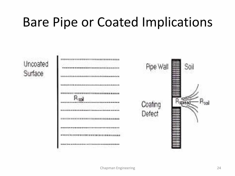
Bare Pipe or Coated Implications
Chapman Engineering 24
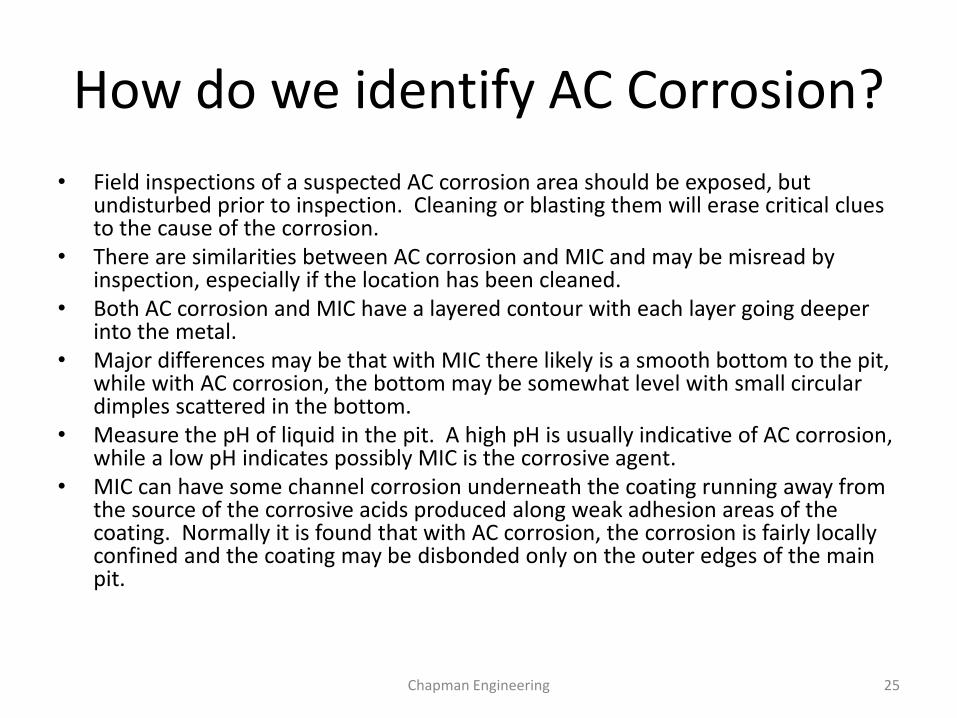
How do we identify AC Corrosion?
• Field inspections of a suspected AC corrosion area should be exposed, but undisturbed prior to inspection. Cleaning or blasting them will erase critical clues to the cause of the corrosion.
• There are similarities between AC corrosion and MIC and may be misread by inspection, especially if the location has been cleaned.
• Both AC corrosion and MIC have a layered contour with each layer going deeper into the metal.
• Major differences may be that with MIC there likely is a smooth bottom to the pit, while with AC corrosion, the bottom may be somewhat level with small circular dimples scattered in the bottom.
• Measure the pH of liquid in the pit. A high pH is usually indicative of AC corrosion, while a low pH indicates possibly MIC is the corrosive agent.
• MIC can have some channel corrosion underneath the coating running away from the source of the corrosive acids produced along weak adhesion areas of the coating. Normally it is found that with AC corrosion, the corrosion is fairly locally confined and the coating may be disbonded only on the outer edges of the main pit.
Chapman Engineering 25
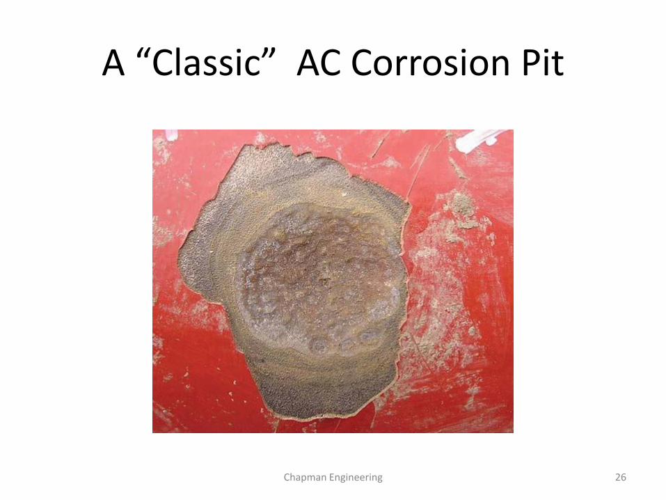
A “Classic” AC Corrosion Pit
Chapman Engineering 26
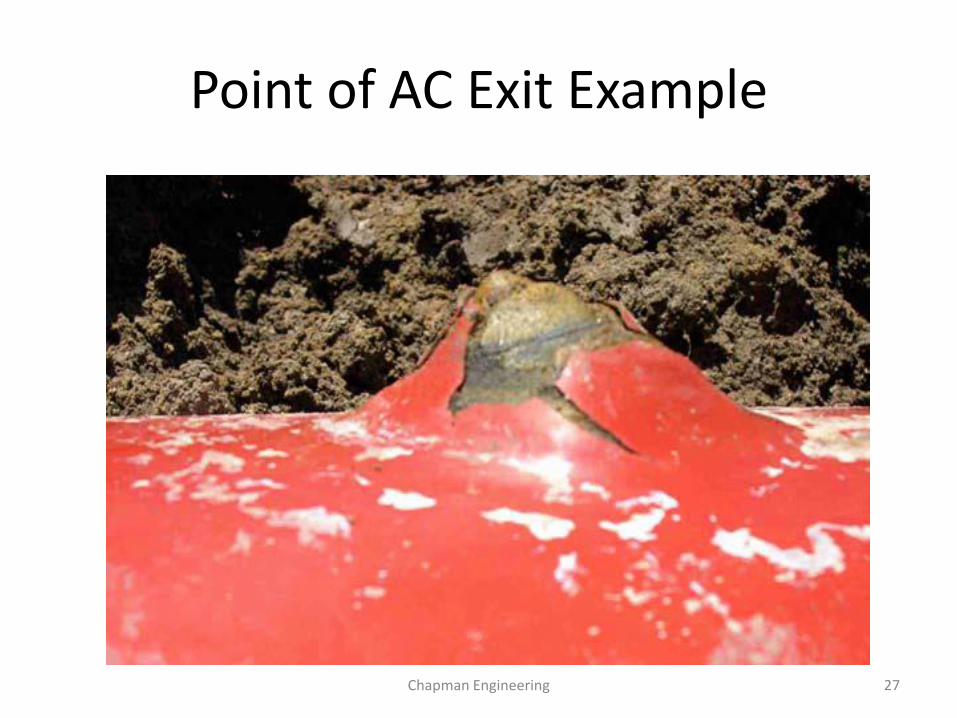
Point of AC Exit Example
Chapman Engineering 27
Difficulty of Inspections When Cleaned
• It is important not to sand blast the anomaly prior to inspections! Important clues can be erased.
• Characteristic shapes and edges are too subtle to establish fully if the corrosion was MIC (probable), or AC corrosion (possible).
• It is very important that the inspection crew sees the anomaly excavated prior to any cleaning or disturbance of the anomaly.
Chapman Engineering 28
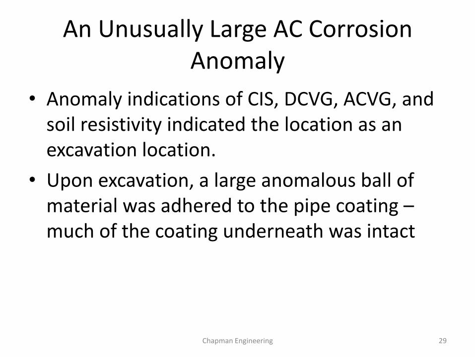
An Unusually Large AC Corrosion Anomaly
• Anomaly indications of CIS, DCVG, ACVG, and soil resistivity indicated the location as an excavation location.
• Upon excavation, a large anomalous ball of material was adhered to the pipe coating – much of the coating underneath was intact
Chapman Engineering 29
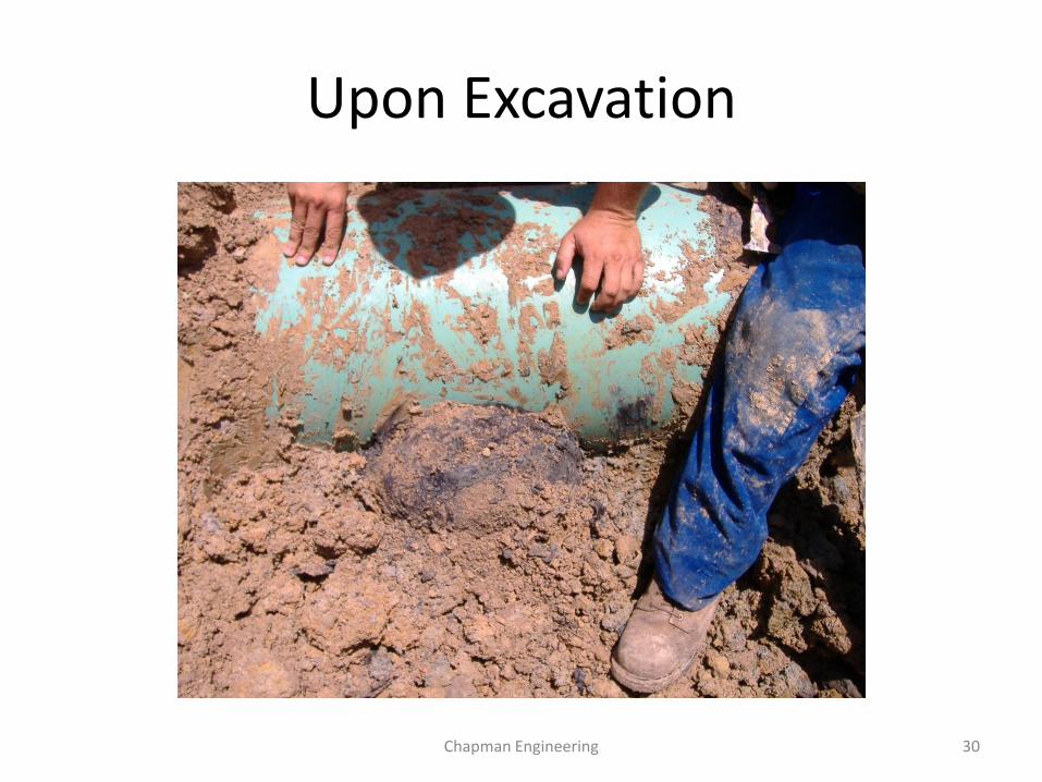
Upon Excavation
Chapman Engineering 30
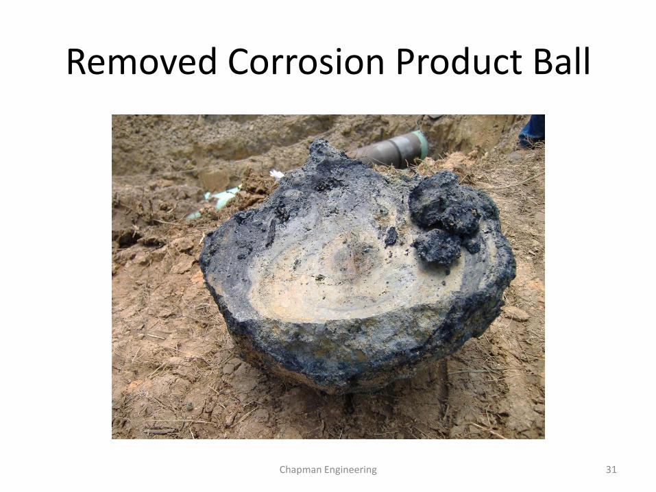
Removed Corrosion Product Ball
Chapman Engineering 31
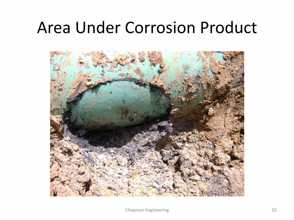
Area Under Corrosion Product
Chapman Engineering 32
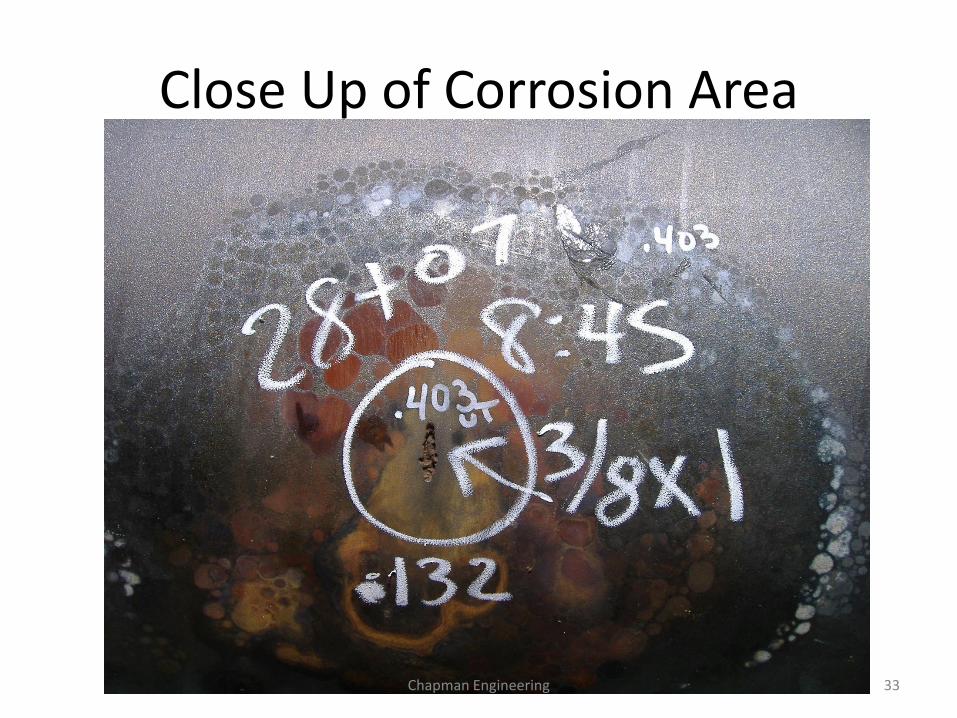
Close Up of Corrosion Area
Chapman Engineering 33
Discussion
• The characteristic shapes of the AC corrosion are noted in the bottom of the pit.
• Layers of corrosion are evident in the pit outer walls, as well as indicated by rings in the corrosion product ball.
• Layers and rings of corrosion product are due to periods of higher current loads, and lower soil resistivity due to rains or soil moisture.
• The corrosion of .132” on a .403” wall indicates a corrosion loss of 32.8%. The time period is unknown.
Chapman Engineering 34
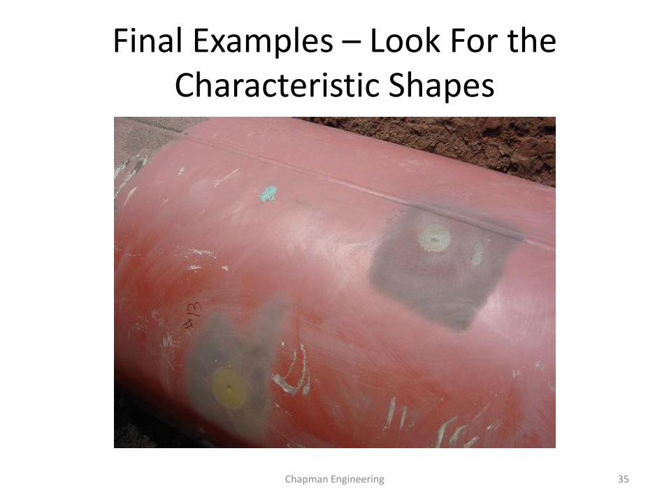
Final Examples – Look For the Characteristic Shapes
Chapman Engineering 35
How do YOU Discover AC Corrosion?
• As PIM procedures mature, more emphasis on surveys will be required to detect AC issues especially in HCA’s.
• Reviewing AC readings on ECDA reports and as found by ILI pig runs with wall loss, a big sign.
• Evaluate likelihood of AC corrosion by estimating current drain from 1cm^2 area, soil resistivity measured in field, and AC potential.
• Request AC corrosion modeling (CDEGS Software or others).
Chapman Engineering 36
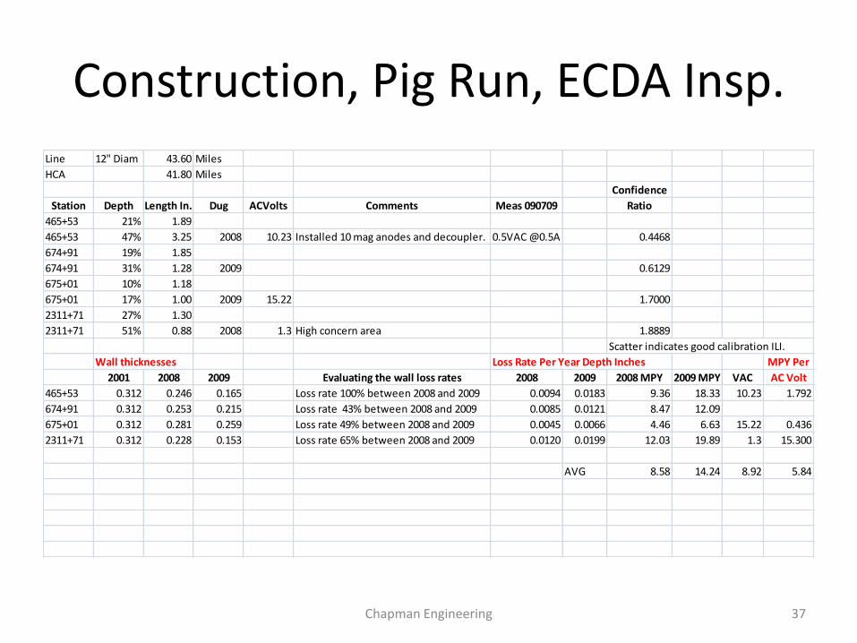
Construction, Pig Run, ECDA Insp.
Line 12" Diam 43.60 Miles
HCA 41.80 Miles
Confidence
Station Depth Length In. Dug ACVolts Comments Meas 090709 Ratio
465+53 21% 1.89
465+53 47% 3.25 2008 10.23 Installed 10 mag anodes and decoupler. 0.5VAC @0.5A 0.4468
674+91 19% 1.85
674+91 31% 1.28 2009 0.6129
675+01 10% 1.18
675+01 17% 1.00 2009 15.22 1.7000
2311+71 27% 1.30
2311+71 51% 0.88 2008 1.3 High concern area 1.8889
Scatter indicates good calibration ILI.
Wall thicknesses Loss Rate Per Year Depth Inches MPY Per
2001 2008 2009 Evaluating the wall loss rates 2008 2009 2008 MPY 2009 MPY VAC AC Volt
465+53 0.312 0.246 0.165 Loss rate 100% between 2008 and 2009 0.0094 0.0183 9.36 18.33 10.23 1.792
674+91 0.312 0.253 0.215 Loss rate 43% between 2008 and 2009 0.0085 0.0121 8.47 12.09
675+01 0.312 0.281 0.259 Loss rate 49% between 2008 and 2009 0.0045 0.0066 4.46 6.63 15.22 0.436
2311+71 0.312 0.228 0.153 Loss rate 65% between 2008 and 2009 0.0120 0.0199 12.03 19.89 1.3 15.300
AVG 8.58 14.24 8.92 5.84
Chapman Engineering 37
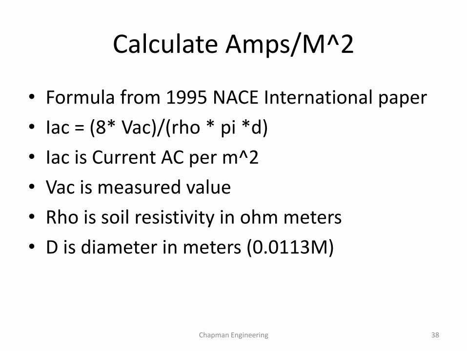
Calculate Amps/M^2
• Formula from 1995 NACE International paper
• Iac = (8* Vac)/(rho * pi *d)
• Iac is Current AC per m^2
• Vac is measured value
• Rho is soil resistivity in ohm meters
• D is diameter in meters (0.0113M)
Chapman Engineering 38
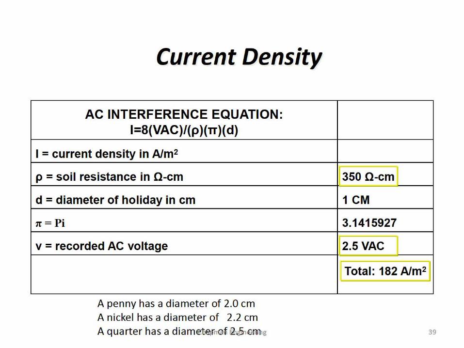
Current Density
AC INTERFERENCE EQUATION: 1=8(VAC)/(p )(TT)( d)
I = current density in A/m2
p = soil resistance in 0-cm
d = diameter of holiday in cm
1t=Pi
v = recorded AC voltage
A penny has a diameter of 2.0 cm A nickel has a diameter of 2.2 cm A quarter has a diam~~nQ~ ~GJrlilig
350 0-cm
1 CM
3.1415927
2.5 VAC
L!_otal: 182 A/m2 ~
39
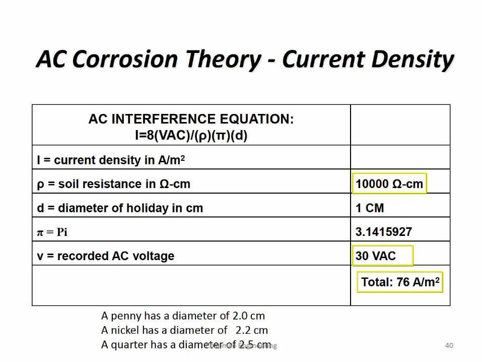
AC Corrosion Theory - Current Density
AC INTERFERENCE EQUATION: 1=8(VAC)/(p )(TT)( d)
I = current density in A/m2
p = soil resistance in 0-cm
d = diameter of holiday in cm
1t=Pi
v = recorded AC voltage
A penny has a diameter of 2.0 cm A nickel has a diameter of 2.2 cm A quarter has a diam~~nQ~ ~GJrlilig
10000 0-cm
1 CM
3.1415927
30VAC
~ Total: 76 A/m21
40
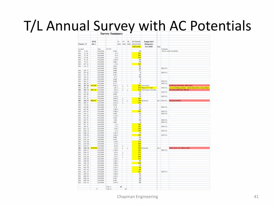
T/L Annual Survey with AC Potentials Survey Summary
DCD >1 >4 >6 AC Density Suggested
Pipeline 12" Sta + VAC VAC VAC W/1cm Def Mitiga tion
>100 Likely For 2009 Deg
Location Date AC P/S Comments
MS: 0 00 9/22/2009 0.394 25 .799 AC AMP ON BOND
MS: 35 38 9/22/2009 2.5 x 161
MS: 35 59 9/22/2009 2.5 x 161
MS: 35 60 9/22/2009 2.5 x 161
MS: 47 42 9/22/2009 1.394 x 90
MS: 78 57 9/22/2009 0.894 58
MS: 107 45 9/22/2009 1.76 x 113
MS: 176 21 9/22/2009 0.876 56
9/22/2009 0.906 58 NEW T/L
MS: 228 75 9/22/2009 0.888 57
MS: 263 64 9/22/2009 0.083 5 NEW T/L
MS: 311 56 9/22/2009 0.161 10
MS: 316 12 9/22/2009 0.77 50
MS: 364 50 9/22/2009 0.048 3
MS: 382 23 9/22/2009 0.088 6 NEW T/L
MS: 404 30 9/22/2009 0.171 11 NEW T/L
MS: 447 66 447+66 9/22/2009 8.561 x x x 551 Point Drains Could be horizontal - wide area
MS: 462 60 9/22/2009 4.91 x x 316 Mags at 0.17 ohms NEW T/L Loc of 10 Mag anodes - need drain here in near future.
MS: 491 74 491+74 9/22/2009 8.92 x x x 574 Point Drains if Possible Loc from 480+16 to 484+52
MS: 518 55 9/22/2009 1.234 x 79 NEW T/L
MS: 565 88 9/22/2009 0.988 64
MS: 583 27 9/22/2009 1.234 x 79 NEW T/L
MS: 617 34 9/22/2009 4.099 x x 264
MS: 665 67 668+67 9/22/2009 10.96 x x x 706 Horizontal Hor 1 NEW T/L Connect at MLV
MS: 668 67 9/22/2009 4.332 x x 279
MS: 774 65 9/22/2009 0.576 37
MS: 818 88 9/22/2009 0.79 51 NEW T/L
MS: 832 89 9/22/2009 1.389 x 89
MS: 876 45 9/22/2009 2.966 x 191 NEW T/L
MS: 910 21 9/22/2009 0.498 32 NEW T/L
MS: 913 78 9/22/2009 1.124 x 72
MS: 915 07 9/22/2009 0.269 17
MS: 929 70 9/22/2009 0.98 63 NEW T/L
MS: 959 26 9/22/2009 0.092 6 NEW T/L
MS: 971 12 9/22/2009 2.1 x 135
MS: 990 25 9/22/2009 2.5 x 161 NEW T/L
MS: 1012 23 9/22/2009 2.38 x 153
MS: 1050 10 9/22/2009 2.2 x 142 NEW T/L
MS: 1086 24 9/22/2009 1.207 x 78
MS: 1100 96 9/22/2009 1.604 x 10³ NEW T/L
MS: 1133 37 9/22/2009 0.989 64
MS: 1181 58 9/22/2009 0.544 35
MS: 1231 80 9/22/2009 2.64 x 170
MS: 1254 48 9/22/2009 3.72 x 240
MS: 1270 87 9/22/2009 4.29 x x 276
MS: 1276 64 1276+64 9/22/2009 5.52 x x x 355 Horizontal Hor 2 Open area, no surface pipe
MS: 1288 47 9/22/2009 2.168 x 140 NEW T/L
MS: 1304 25 9/22/2009 4.26 x x 274
MS: 1315 41 9/22/2009 4.26 x x 274
MS: 1326 00 9/22/2009 4.35 x x 280
MS: 1360 90 9/22/2009 3.294 x 212
MS: 1388 80 9/22/2009 1.446 x 93
MS: 1395 30 9/22/2009 1.688 x 10⁹
MS: 1415 65 9/22/2009 1.184 x 76
MS: 1447 89 9/22/2009 1.542 x 99
MS: 1447 90 9/22/2009 1.542 x 99
MS: 1451 47 9/22/2009 1.565 x 101 NEW T/L
MS: 1459 65 9/22/2009 1.408 x 91
MS: 1466 85 9/22/2009 1.221 x 79
MS: 1484 20 9/22/2009 0.439 28
MS: 1499 49 9/22/2009 0.445 29
MS: 1523 41 9/22/2009 1.007 x 65
VAC>1 39
7 VAC>4 11
Chapman Engineering 41
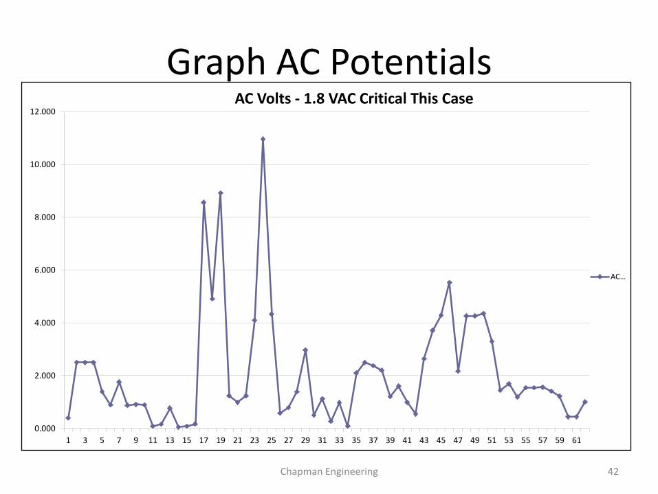
Graph AC Potentials
0.000
2.000
4.000
6.000
8.000
10.000
12.000
1 3 5 7 9 11 13 15 17 19 21 23 25 27 29 31 33 35 37 39 41 43 45 47 49 51 53 55 57 59 61
AC Volts - 1.8 VAC Critical This Case
AC…
Chapman Engineering 42
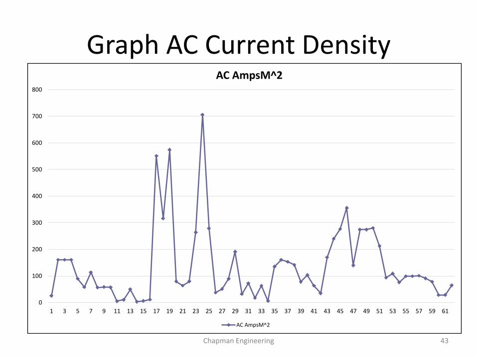
Graph AC Current Density
0
100
200
300
400
500
600
700
800
1 3 5 7 9 11 13 15 17 19 21 23 25 27 29 31 33 35 37 39 41 43 45 47 49 51 53 55 57 59 61
AC AmpsM^2
AC AmpsM^2
Chapman Engineering 43
How is AC Safety Mitigated?
• Locations of pipe to soil test leads, and any surface pipeline appurtenance can be measured to determine locations of possibly high enough voltage to require mitigation for safety. Accurate modeling will also disclose areas of expected safety issues.
• These locations can be mitigated with short runs of material that can permanently shunt the current to the power line ground system economically.
• Step potentials must be considered in these areas, and normally, step potential mats are indicated in all locations of surface pipe appurtenances such as block valves and risers to protect personnel
• All Test Lead contacts in high potential power line ROW parallel systems should be dead face front style to prevent contact with personnel. Covers are also indicated as further assurance of protection from public interaction in areas of high population densities.
Chapman Engineering 44
Other Safety Hazards
• Test leads attach directly to the pipeline can have dangerous AC Voltages, and should be of the “dead face front” style, so no electrical contact is possible to the person taking readings.
• Pipeline bonds also may have high AC Voltages in these areas and should also be constructed so no physical contact is made by the technician.
• Can you think of another significant possible shock hazard item in these areas?
Chapman Engineering 45
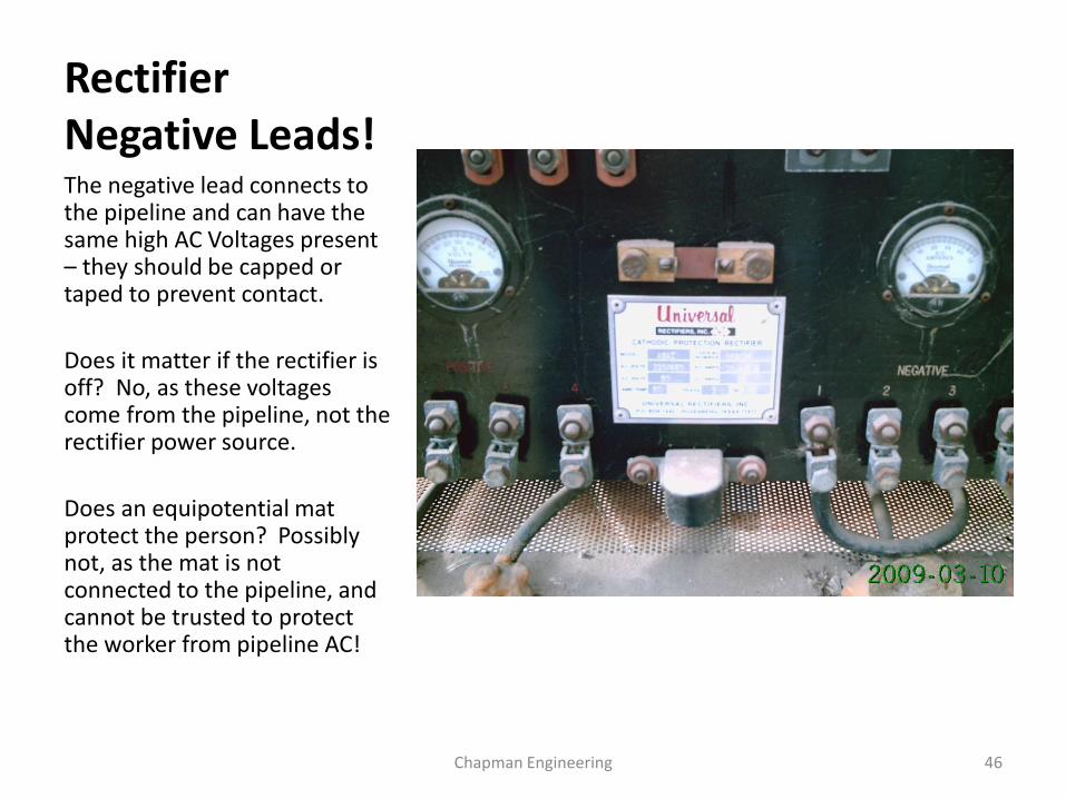
Rectifier Negative Leads! The negative lead connects to the pipeline and can have the same high AC Voltages present – they should be capped or taped to prevent contact.
Does it matter if the rectifier is off? No, as these voltages come from the pipeline, not the rectifier power source.
Does an equipotential mat protect the person? Possibly not, as the mat is not connected to the pipeline, and cannot be trusted to protect the worker from pipeline AC!
Chapman Engineering 46
AC Corrosion Theory - Summary
• Induced AC voltage may be a cause of corrosion at coating defects where AC current escapes the pipe wall into the soil.
• Small rather than large coating defects are susceptible to AC corrosion effects.
• The surface area of the pipe at a coating holiday is important since the corrosion rate increases with increasing current density.
• Large holidays would have a lower current density than small holidays if both were exposed to the same soil conditions.
Chapman Engineering 47
How are AC Corrosion Issues Mitigated?
• A cookie cutter approach may be used, but cannot be assured of success as there may be areas that have not been modeled and found that can have significant issues of AC corrosion that may not be covered by short isolated segments of parallel or deep well drains.
• Areas for spot installations or longer runs of material may be disclosed by a good interpretation of the topography, and looking for areas of divergence and convergence between the pipeline and the power lines involved.
• Areas of known high current density may be generally indicated at major divergence points, and near power line substations, but many others may be on the line, and not discovered without field surveys and appropriate modeling of the systems. It is strongly suggested any line with discovered AC corrosion wall losses should be modeled and an appropriate complete system installation designed and proposed for consideration.
Chapman Engineering 48
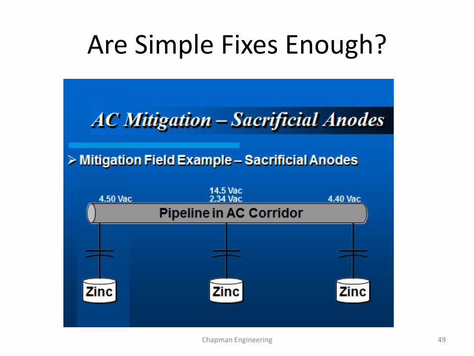
Are Simple Fixes Enough?
Chapman Engineering 49
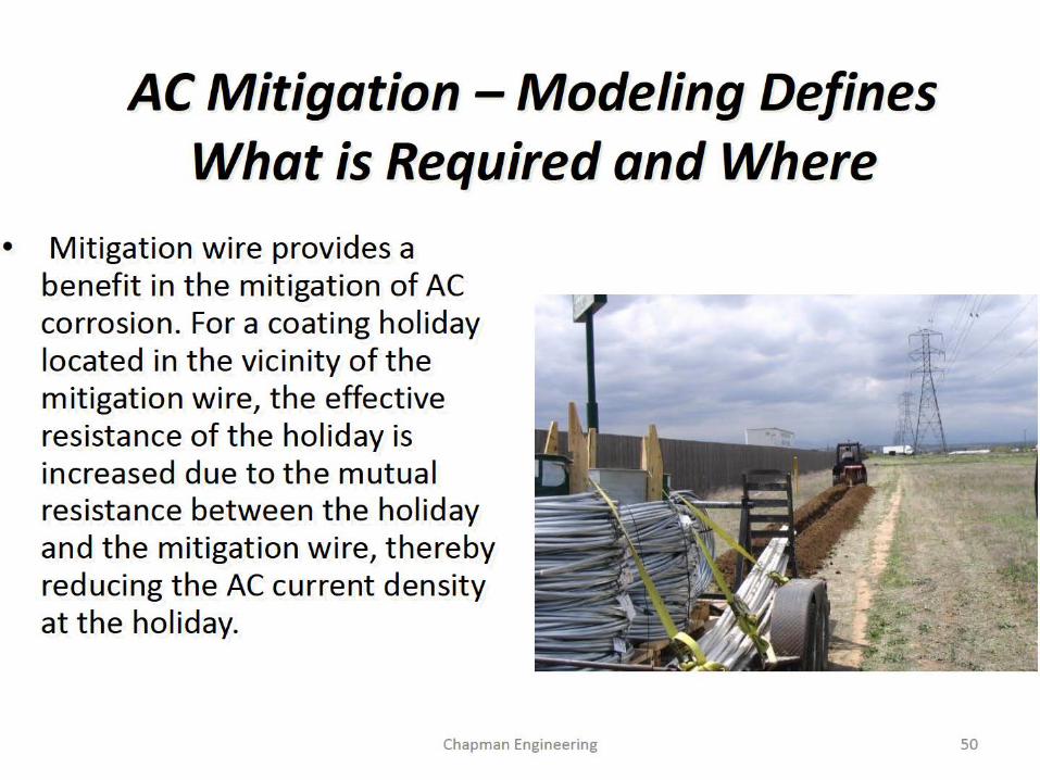
AC Mitigation - Modeling Defines What is Required and Where
• Mitigation wire provides a benefit in the mitigation of AC corrosion. For a coating holiday located in the vicinity of the mitigation wire, the effective resistance of the holiday is increased due to the mutual resistance between the holiday and the mitigation wire, thereby reducing the AC current density at the holiday.
Chapman Engineering 50
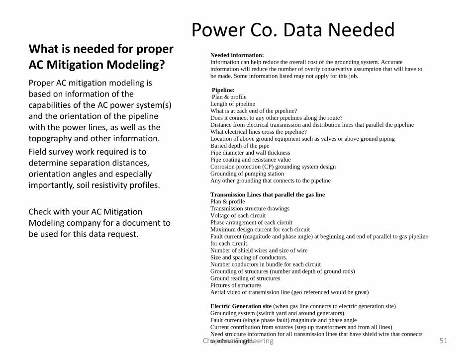
What is needed for proper AC Mitigation Modeling?
Power Co. Data Needed
Proper AC mitigation modeling is based on information of the capabilities of the AC power system(s) and the orientation of the pipeline with the power lines, as well as the topography and other information.
Field survey work required is to determine separation distances, orientation angles and especially importantly, soil resistivity profiles.
Check with your AC Mitigation Modeling company for a document to be used for this data request.
Needed information:
Information can help reduce the overall cost of the grounding system. Accurate
information will reduce the number of overly conservative assumption that will have to
be made. Some information listed may not apply for this job.
Pipeline:
Plan & profile
Length of pipeline
What is at each end of the pipeline?
Does it connect to any other pipelines along the route?
Distance from electrical transmission and distribution lines that parallel the pipeline
What electrical lines cross the pipeline?
Location of above ground equipment such as valves or above ground piping
Buried depth of the pipe
Pipe diameter and wall thickness
Pipe coating and resistance value
Corrosion protection (CP) grounding system design
Grounding of pumping station
Any other grounding that connects to the pipeline
Transmission Lines that parallel the gas line
Plan & profile
Transmission structure drawings
Voltage of each circuit
Phase arrangement of each circuit
Maximum design current for each circuit
Fault current (magnitude and phase angle) at beginning and end of parallel to gas pipeline
for each circuit.
Number of shield wires and size of wire
Size and spacing of conductors.
Number conductors in bundle for each circuit
Grounding of structures (number and depth of ground rods)
Ground reading of structures
Pictures of structures
Aerial video of transmission line (geo referenced would be great)
Electric Generation site (when gas line connects to electric generation site)
Grounding system (switch yard and around generators).
Fault current (single phase fault) magnitude and phase angle
Current contribution from sources (step up transformers and from all lines)
Need structure information for all transmission lines that have shield wire that connects
to substation grid. Chapman Engineering 51
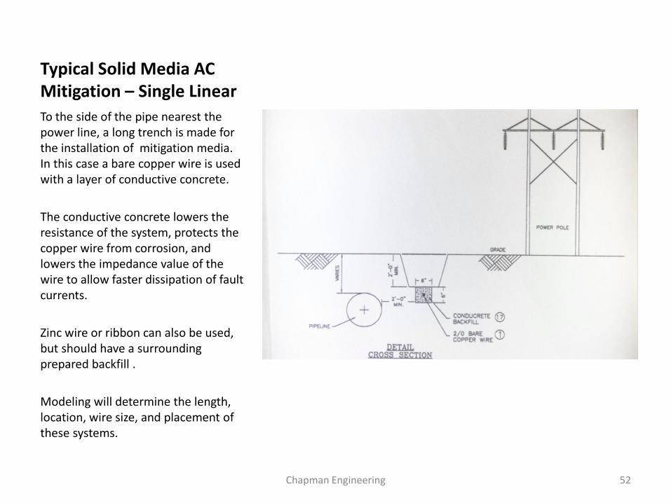
Typical Solid Media AC Mitigation – Single Linear
To the side of the pipe nearest the power line, a long trench is made for the installation of mitigation media. In this case a bare copper wire is used with a layer of conductive concrete.
The conductive concrete lowers the resistance of the system, protects the copper wire from corrosion, and lowers the impedance value of the wire to allow faster dissipation of fault currents.
Zinc wire or ribbon can also be used, but should have a surrounding prepared backfill .
Modeling will determine the length, location, wire size, and placement of these systems.
Chapman Engineering 52
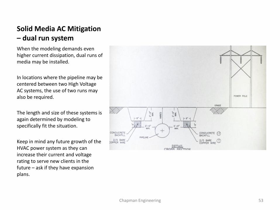
Solid Media AC Mitigation – dual run system
When the modeling demands even higher current dissipation, dual runs of media may be installed.
In locations where the pipeline may be centered between two High Voltage AC systems, the use of two runs may also be required.
The length and size of these systems is again determined by modeling to specifically fit the situation.
Keep in mind any future growth of the HVAC power system as they can increase their current and voltage rating to serve new clients in the future – ask if they have expansion plans.
Chapman Engineering 53
Types of AC Mitigation for Corrosion Control
• Linear grounding systems – allow the dissipation of AC current through the soil back to the power line grounding. – Various materials are used including zinc, copper, and
steel
• Point Drain grounding – these systems are similar to deep wells in that they use vertical elements into the soil to achieve low resistance grounding to carry localized area AC currents back to the power line system. – Normally for low angle crossings or deviation points
Chapman Engineering 54
Grounding Materials Used
• Zinc Ribbon or Wire • Zinc over steel wire • Copper Wire • Combination Steel over
Copper Wire • Steel Wire
• Common Backfills
– Native Soil – Bentonite – Conductive Concretes
Chapman Engineering 55
Issues with Grounding Materials
• Zinc systems have been problematic in some ways, including passivation and issues of corrosion of the zinc media and jointing areas. – In areas of high sulfur content in the soil
(agricultural fertilizers, etc) zinc can form a surface coating of Zinc Sulfate which has a resistivity value of 6,000,000 ohm cm and can diminish the zinc from being able to pass current.
– Directly connecting zinc can increase the burden on CP systems.
Chapman Engineering 56
Issues with Grounding Materials
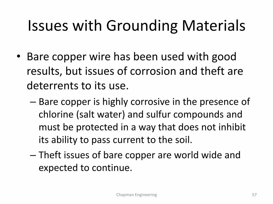
• Bare copper wire has been used with good results, but issues of corrosion and theft are deterrents to its use.
– Bare copper is highly corrosive in the presence of chlorine (salt water) and sulfur compounds and must be protected in a way that does not inhibit its ability to pass current to the soil.
– Theft issues of bare copper are world wide and expected to continue.
Chapman Engineering 57
Steel Grounding Systems
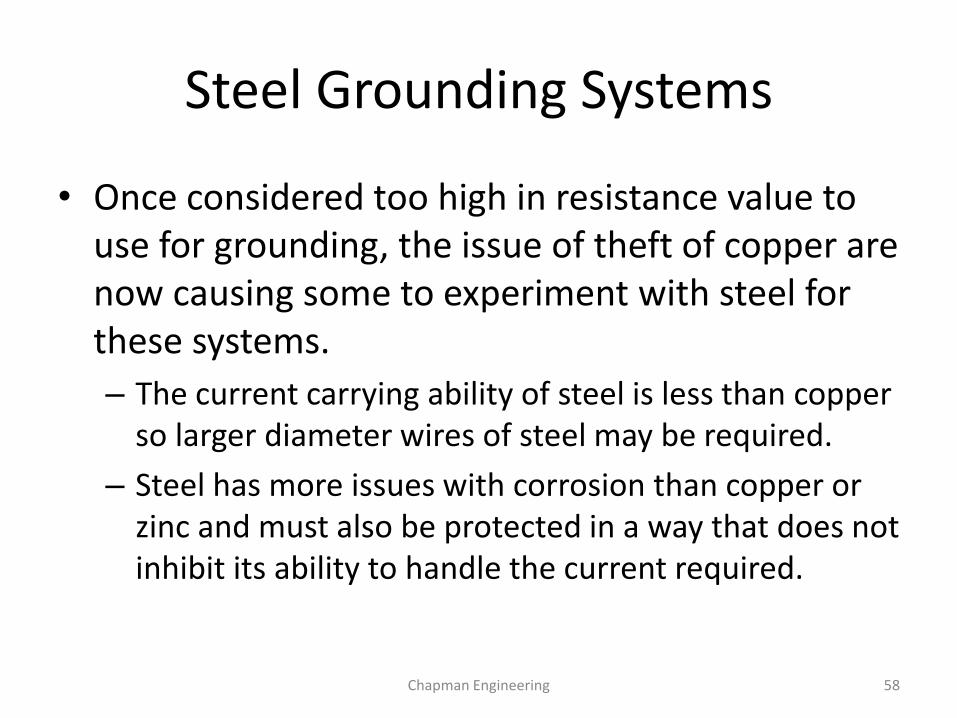
• Once considered too high in resistance value to use for grounding, the issue of theft of copper are now causing some to experiment with steel for these systems.
– The current carrying ability of steel is less than copper so larger diameter wires of steel may be required.
– Steel has more issues with corrosion than copper or zinc and must also be protected in a way that does not inhibit its ability to handle the current required.
Chapman Engineering 58
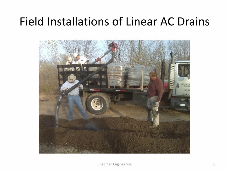
Field Installations of Linear AC Drains
Chapman Engineering 59
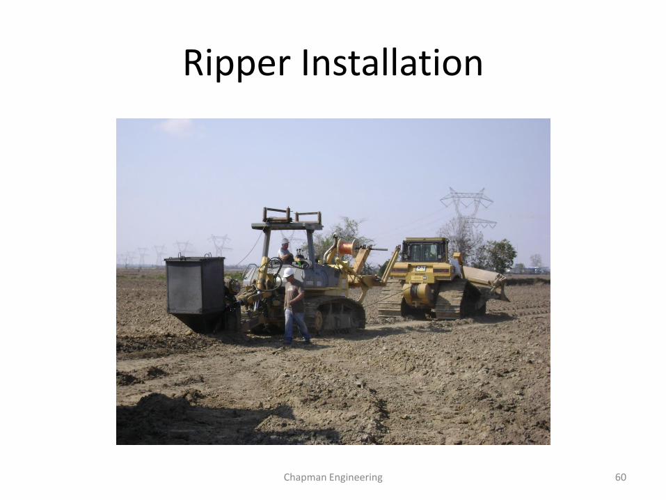
Ripper Installation
Chapman Engineering 60
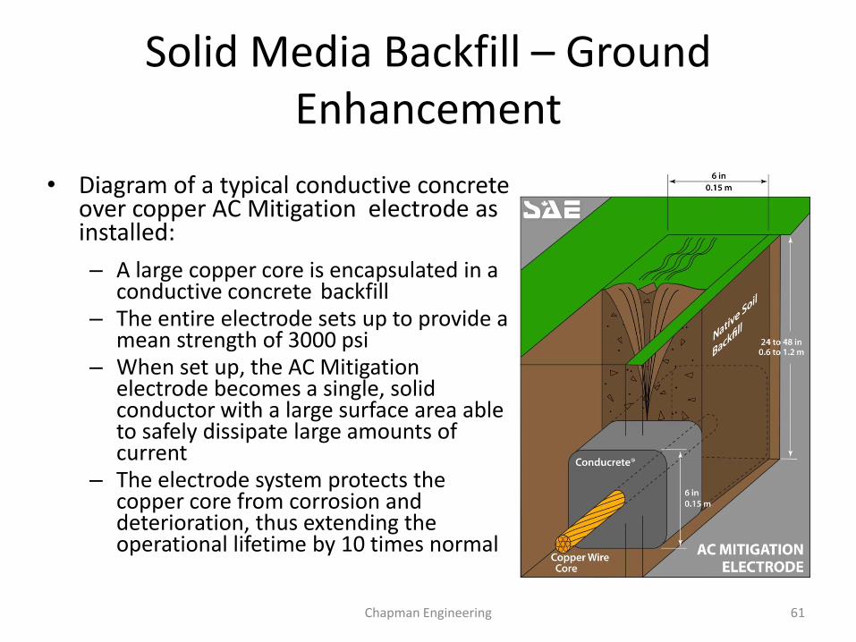
Solid Media Backfill – Ground Enhancement
• Diagram of a typical conductive concrete over copper AC Mitigation electrode as installed: – A large copper core is encapsulated in a
conductive concrete backfill – The entire electrode sets up to provide a
mean strength of 3000 psi – When set up, the AC Mitigation
electrode becomes a single, solid conductor with a large surface area able to safely dissipate large amounts of current
– The electrode system protects the copper core from corrosion and deterioration, thus extending the operational lifetime by 10 times normal
Chapman Engineering 61
0 1--' I'.) w .i:. U1 °' 0 0
0 0
0 0
0 0
0 0
0 0
0 0
0 0 0 0 0 0 0
1 12 23 :::c 34 m 45 Vl 56 67 c 78 -r+ 89 Vl
100 111 n 122
0 133 144 "'O 155 "'O 166 177 m
n 188 ...., :::; 199 '"'-...... QI
"O 210 n 3 QI 221 ::J 0 m 232 ::J
:J ~. 243 ::J ro 254 a. ro ::::!. 265 ::J c O'Q 276
287 n 298 r+ 309 -· 320 < 331 m 342 353 n 364 0 375 386 :J 397 n 408 ...., 419 m 430 r+
f m Vl <ll .., a;·
CJ) V>
N 1--'
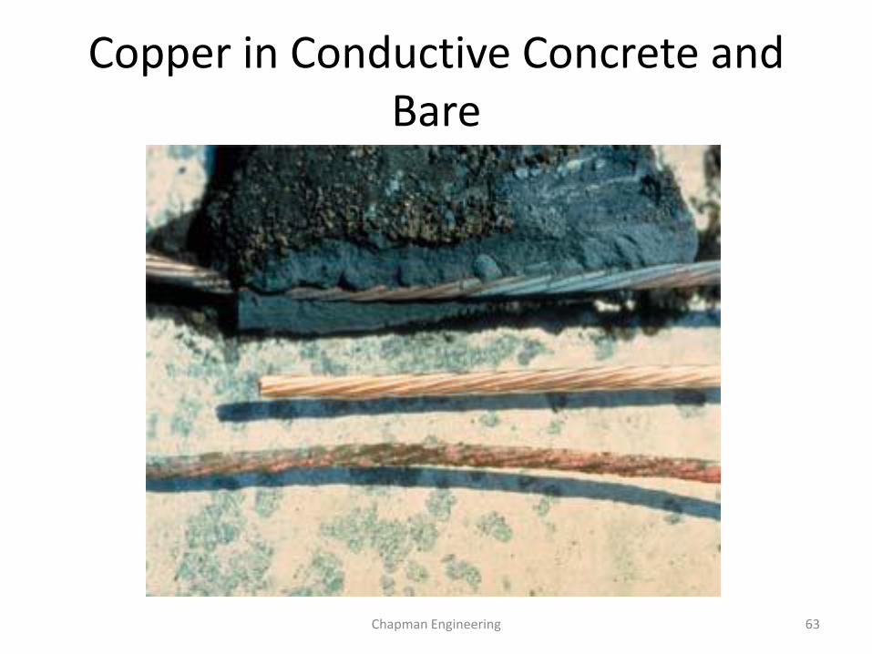
Copper in Conductive Concrete and Bare
Chapman Engineering 63
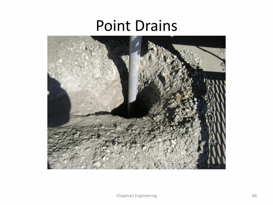
Point Drains
Chapman Engineering 64
Solid Media Backfill – Conductive Concrete
• Conductive concrete can have a resistivity of 3 ohm/cm • It has the same porosity as bentonite • It is hygroscopic and will retain moisture • It has been used to enhance grounding systems for
over 100 years (Marconites). • It reduces impedance and resistance of AC mitigation
systems and enhances their ability to pass current to the earth.
• It reduces the electrolytic corrosion process of copper by over 85% to 90%, extending copper life to 50 years or more in AC Mitigation service.
Chapman Engineering 65
Lightning Damage
Chapman Engineering 66
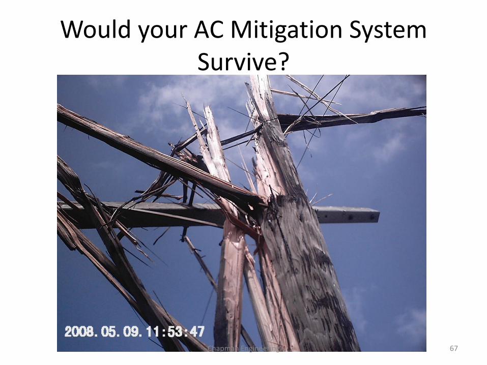
Would your AC Mitigation System Survive?
Chapman Engineering 67
Questions or Comments
• For technical support contact
Mike Ames
Chapman Engineering
Houston, TX
713 598 7042 cell, 800-375-7747 office
www.chapman.engineering
Chapman Engineering 68