AC Combined Module for SATCO (Functionality)
174
Chapter 1 – Introduction to AT3 1
description
AC Combined Module for SATCO (Functionality)
Transcript of AC Combined Module for SATCO (Functionality)
Chapter 1 – Introduction to AT3
1

Contents
ATMS Architecture
Major systems of ATMS
Key Functionality
Working Positions and Roles
Day 1 Seating Plan
Working Positions Layout
AC working position
Introduction of AT3
2
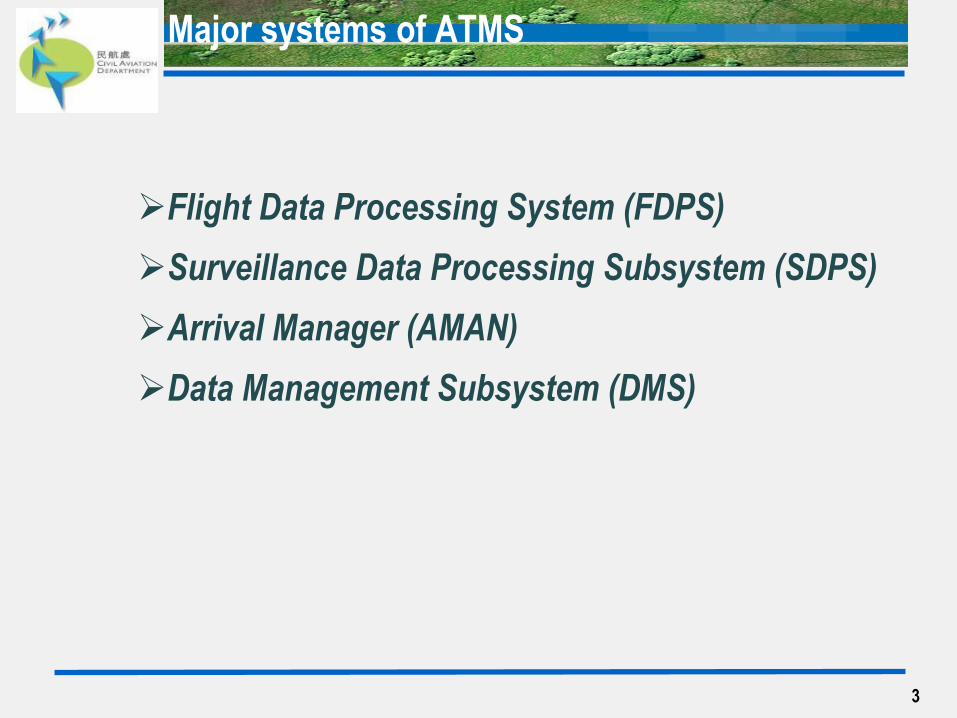
Major systems of ATMS
Flight Data Processing System (FDPS)
Surveillance Data Processing Subsystem (SDPS)
Arrival Manager (AMAN)
Data Management Subsystem (DMS)
3

Key Functions - FDPS
Features Main processing element
Complete picture of flight movement
Key functionality Trajectory processing
Processing and granting clearances
Conflict prediction
Flight / track association
Airspace management
4
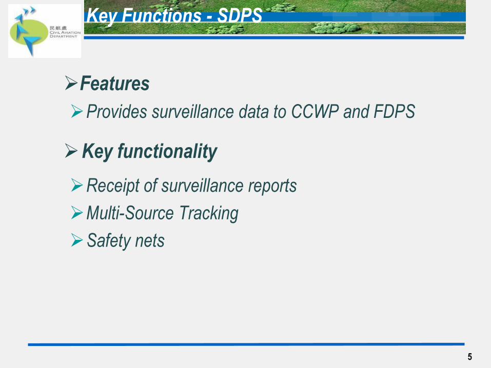
Features
Provides surveillance data to CCWP and FDPS
Key functionality
Receipt of surveillance reports
Multi-Source Tracking
Safety nets
Key Functions - SDPS
5
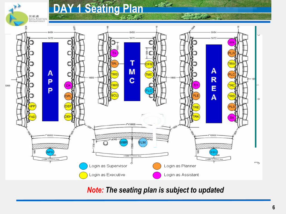
DAY 1 Seating Plan
Note: The seating plan is subject to updated
6
7
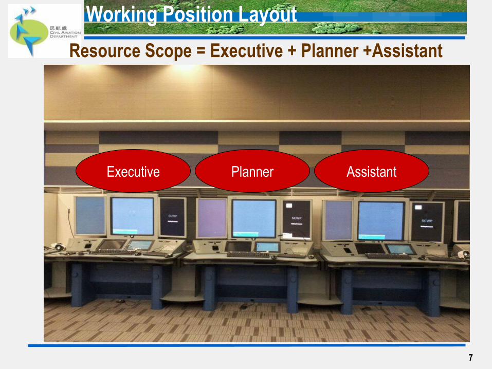
Resource Scope = Executive + Planner +Assistant
Executive Planner Assistant
Working Position Layout
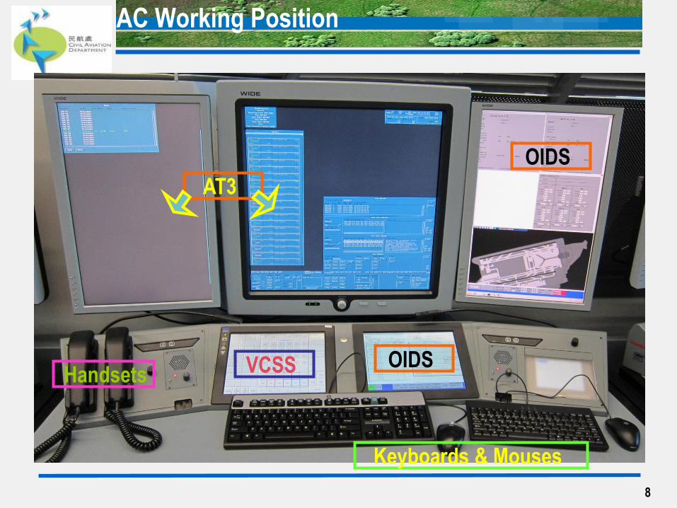
AC Working Position
8
OIDS
VCSS OIDS
Keyboards & Mouses
Handsets
AT3

9
Chapter 2 Auto Trac 3 HMI
Window Frame Features
Monitors of AT3
Use of Mouse
Hot key table
10
Human Machine Interface (HMI)
11
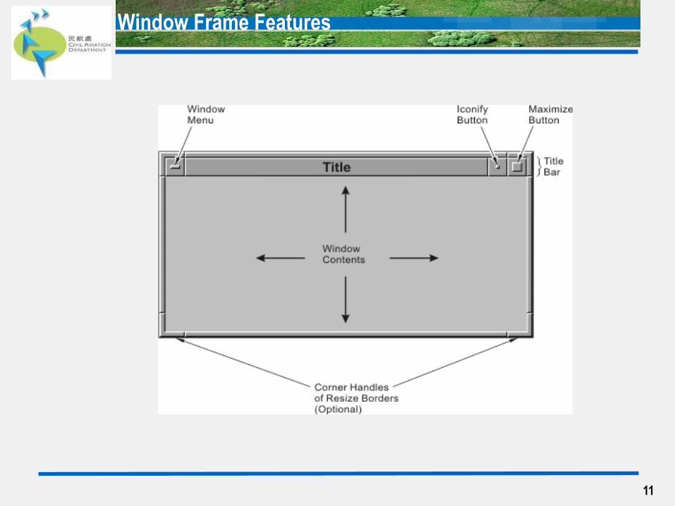
Window Frame Features
12
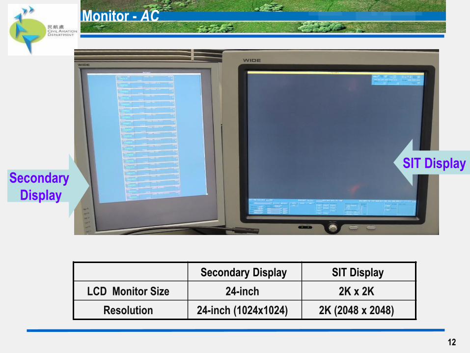
Monitor - AC
Secondary Display SIT Display
LCD Monitor Size 24-inch 2K x 2K
Resolution 24-inch (1024x1024) 2K (2048 x 2048)
Secondary
Display
SIT Display
13
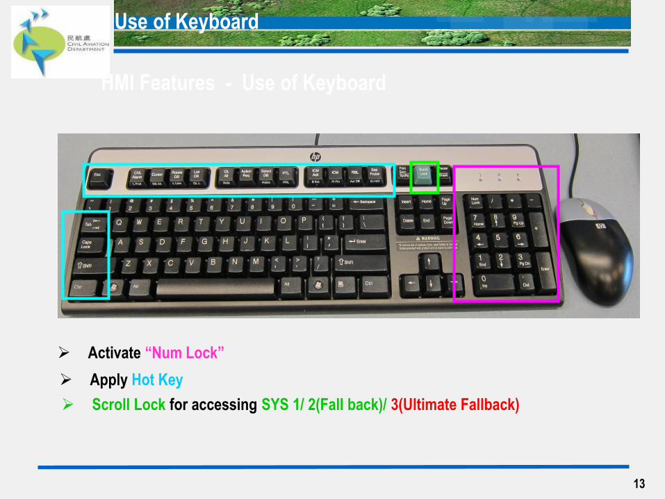
HMI Features - Use of Keyboard
Activate “Num Lock”
Apply Hot Key
Scroll Lock for accessing SYS 1/ 2(Fall back)/ 3(Ultimate Fallback)
Use of Keyboard
14
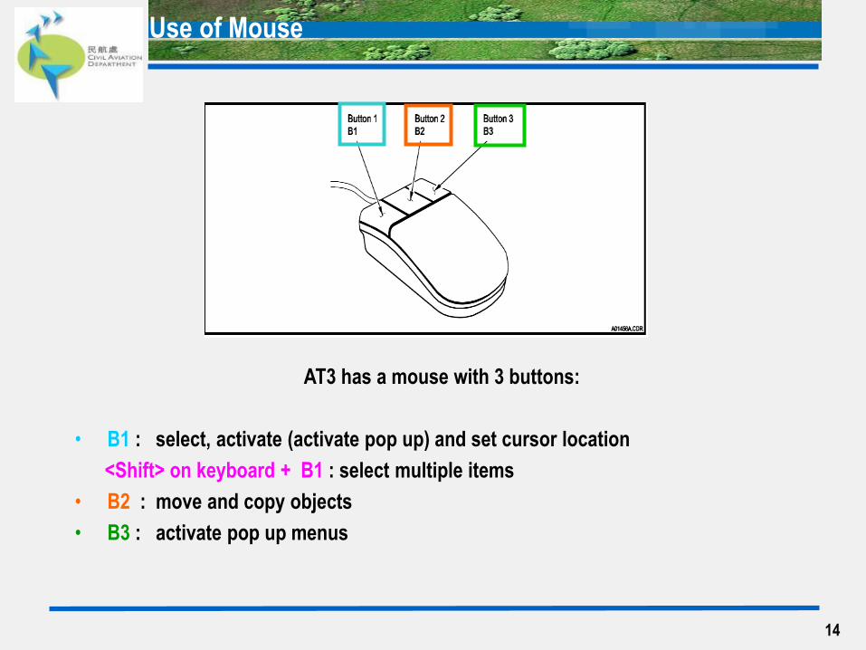
AT3 has a mouse with 3 buttons:
• B1 : select, activate (activate pop up) and set cursor location
<Shift> on keyboard + B1 : select multiple items
• B2 : move and copy objects
• B3 : activate pop up menus
Use of Mouse
15
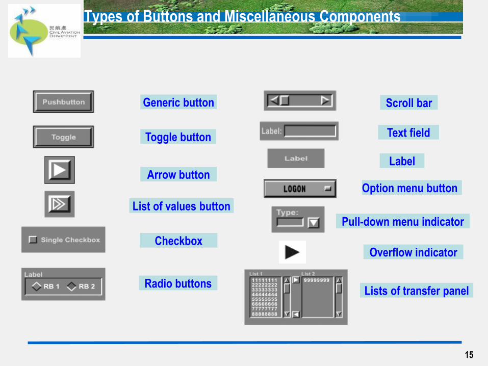
Generic button
Toggle button
Arrow button
List of values button
Checkbox
Radio buttons
Scroll bar
Text field
Label
Option menu button
Pull-down menu indicator
Overflow indicator
Lists of transfer panel
Types of Buttons and Miscellaneous Components
16
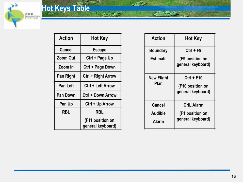
Hot Keys Table
Action Hot Key
Cancel Escape
Zoom Out Ctrl + Page Up
Zoom In Ctrl + Page Down
Pan Right Ctrl + Right Arrow
Pan Left Ctrl + Left Arrow
Pan Down Ctrl + Down Arrow
Pan Up Ctrl + Up Arrow
RBL RBL
(F11 position on
general keyboard)
Action Hot Key
Boundary
Estimate
Ctrl + F9
(F9 position on
general keyboard)
New Flight
Plan
Ctrl + F10
(F10 position on
general keyboard)
Cancel
Audible
Alarm
CNL Alarm
(F1 position on
general keyboard)
17
Active Log On Page
Assistant Role
Role Option Page
Assume Role Page
Types of Log On
Jurisdiction (CJS)
Multiple Jurisdictions Selection
Log Off Page - for All Roles
Log On & Log Off the AT3
18
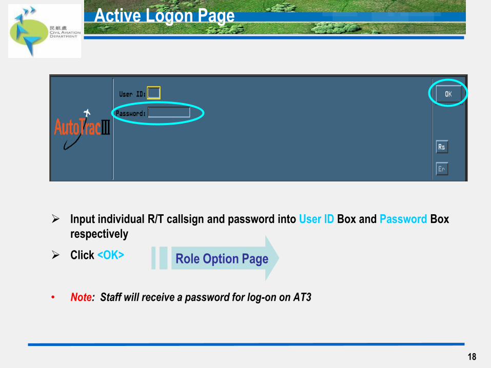
Active Logon Page
Input individual R/T callsign and password into User ID Box and Password Box
respectively
Click <OK>
• Note: Staff will receive a password for log-on on AT3
Role Option Page
19
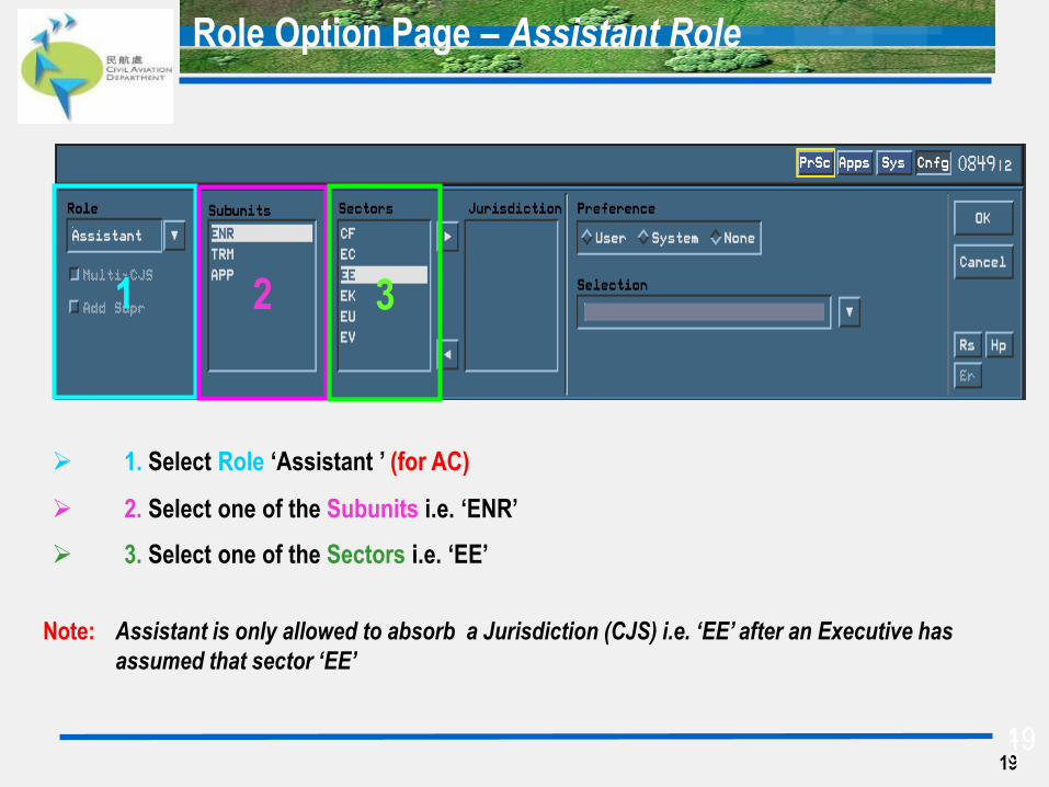
Role Option Page – Assistant Role
1 2 3
1. Select Role ‘Assistant ’ (for AC)
2. Select one of the Subunits i.e. ‘ENR’
3. Select one of the Sectors i.e. ‘EE’
Note: Assistant is only allowed to absorb a Jurisdiction (CJS) i.e. ‘EE’ after an Executive has
assumed that sector ‘EE’
1
9 19
20
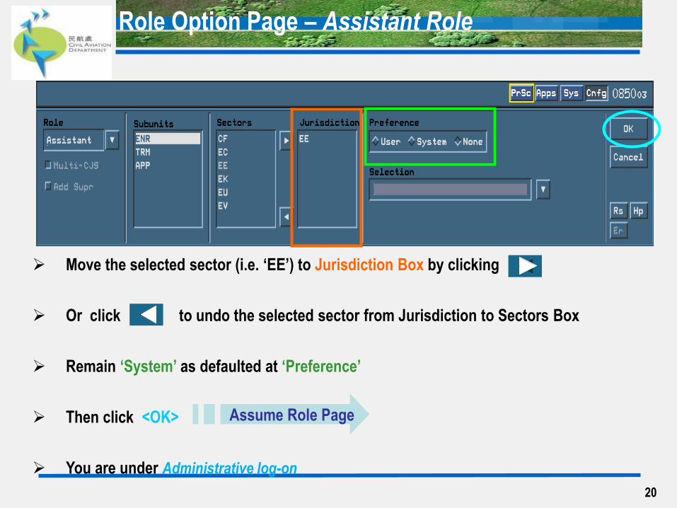
Role Option Page – Assistant Role
Move the selected sector (i.e. ‘EE’) to Jurisdiction Box by clicking
Or click to undo the selected sector from Jurisdiction to Sectors Box
Remain ‘System’ as defaulted at ‘Preference’
Then click <OK>
You are under Administrative log-on
Assume Role Page
21
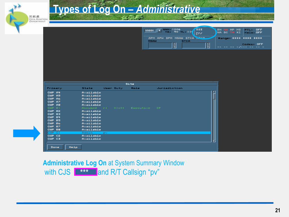
Types of Log On – Administrative
Administrative Log On at System Summary Window
with CJS and R/T Callsign “pv”
***
22
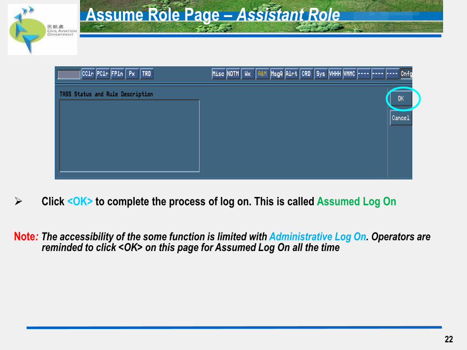
Assume Role Page – Assistant Role
Click <OK> to complete the process of log on. This is called Assumed Log On
Note: The accessibility of the some function is limited with Administrative Log On. Operators are reminded to click <OK> on this page for Assumed Log On all the time
23
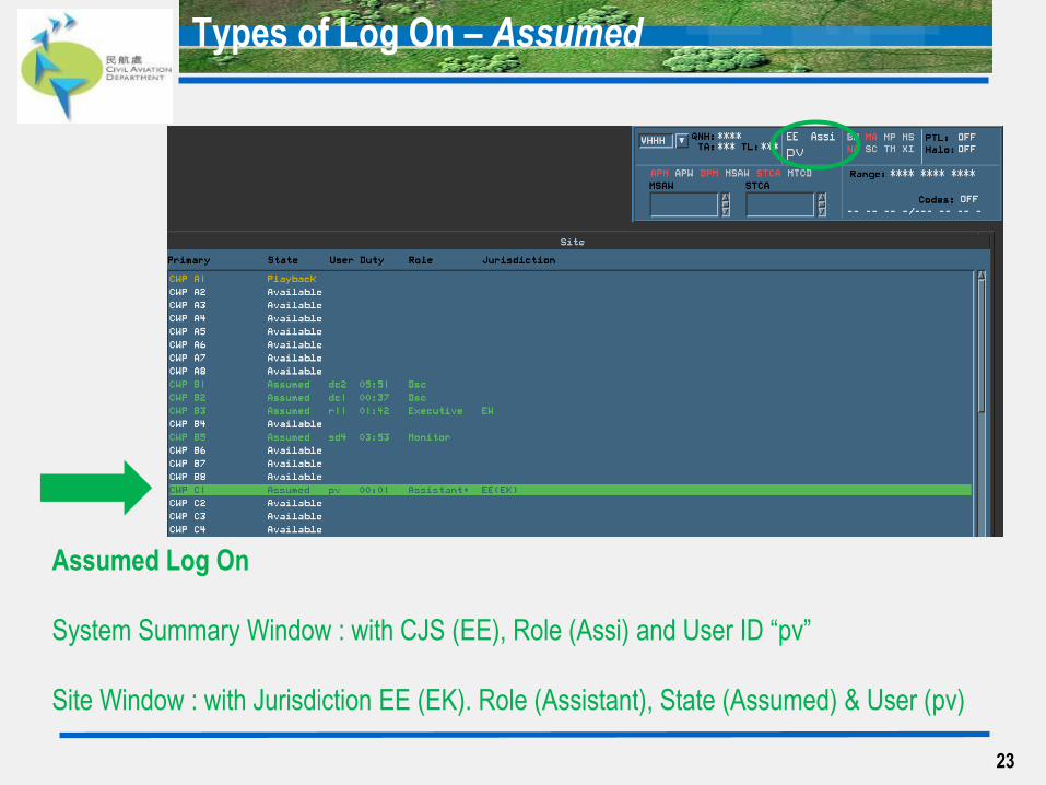
Types of Log On – Assumed
Assumed Log On
System Summary Window : with CJS (EE), Role (Assi) and User ID “pv”
Site Window : with Jurisdiction EE (EK). Role (Assistant), State (Assumed) & User (pv)
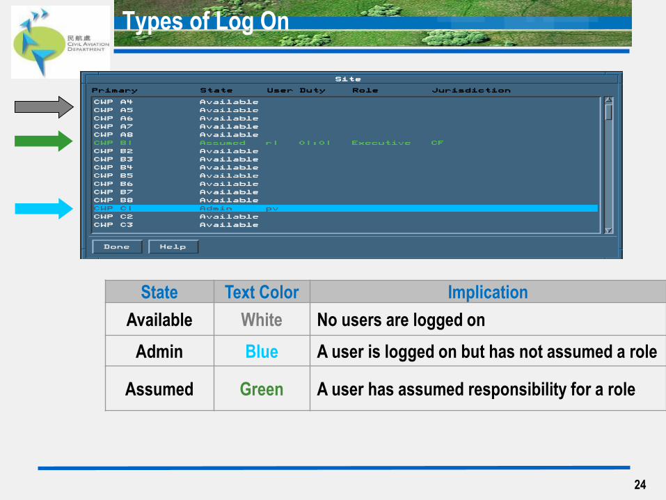
24
Types of Log On
State Text Color Implication
Available White No users are logged on
Admin Blue A user is logged on but has not assumed a role
Assumed Green A user has assumed responsibility for a role
25
Resource Scope = Executive + Planner +Assistant
• Adaptation of same CJS: 1 Executive + maximum 3 Assistants
Sequence to Assume CJS
• Executive selects CJS(s), then Assistant can follow to absorb the same CJS(s)
• Example: Executive selects CJS ‘EE’ as Master, then absorbs ‘EK, ME’ as Slave.
Afterwards, Assistant only needs to select ‘EE’, the Slave CJS ‘EK, ME’ will be
absorbed automatically
Example of manning ACE Helper
• Assistant can absorb more than 1 Master CJS at the same time
• ACE helper selects 2 Master sectors (‘EE’ + ‘EW’) in order to access the same resources of
East and West Sectors i.e. the EFS of both sectors
General Notes of Jurisdiction (CJS) – Assistant Role

26
Working Positions, Designators and CJS (Controller Jurisdiction Symbol)
Sector Executive Role
Designator (CJS)
Planner Role
(Designator)
Assistant Role
(Designator)
Area
East
TRE (EE) Planner East
(PLE)
East Assistant
(EA) TRK (EK)
Area
South TRS (ES)
Planner South
(PLS) South Assistant
(SA) Area
Central TRC1 (EC)
Planner Central
(PLC)
Area
West
TRW (EW) Planner West
(PLW)
West Assistant
(WA) TRC2 (EV)
27
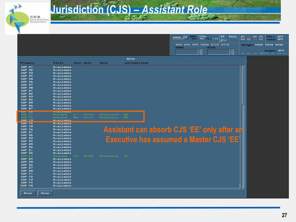
Jurisdiction (CJS) – Assistant Role
Assistant can absorb CJS ‘EE’ only after an
Executive has assumed a Master CJS ‘EE’
28
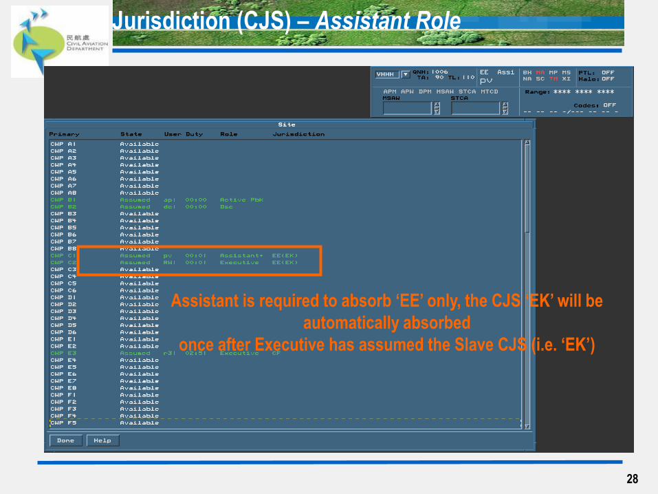
Jurisdiction (CJS) – Assistant Role
Assistant is required to absorb ‘EE’ only, the CJS ‘EK’ will be
automatically absorbed
once after Executive has assumed the Slave CJS (i.e. ‘EK’)
29
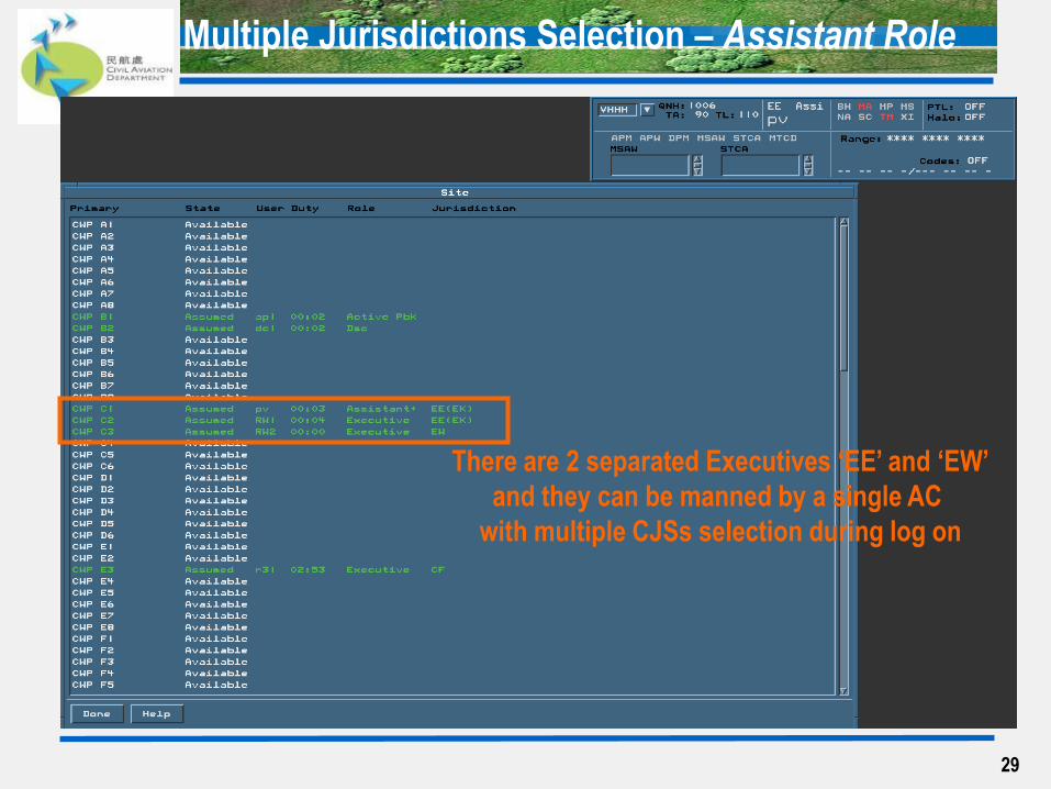
Multiple Jurisdictions Selection – Assistant Role
There are 2 separated Executives ‘EE’ and ‘EW’
and they can be manned by a single AC
with multiple CJSs selection during log on

30
Multiple Jurisdictions Selection – Assistant Role
3 2 4 1
1. Select Role ‘Assistant ’
2. Select one of the Subunits i.e. ‘ENR’
3. Select one of the Sectors i.e. ‘EE’ & ‘EW’
4. Move the selected sector i.e. ‘EE’ & ‘EW’ to Jurisdiction Box by clicking
31
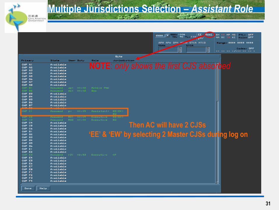
Multiple Jurisdictions Selection – Assistant Role
Then AC will have 2 CJSs
‘EE’ & ‘EW’ by selecting 2 Master CJSs during log on
NOTE: only shows the first CJS absorbed
32
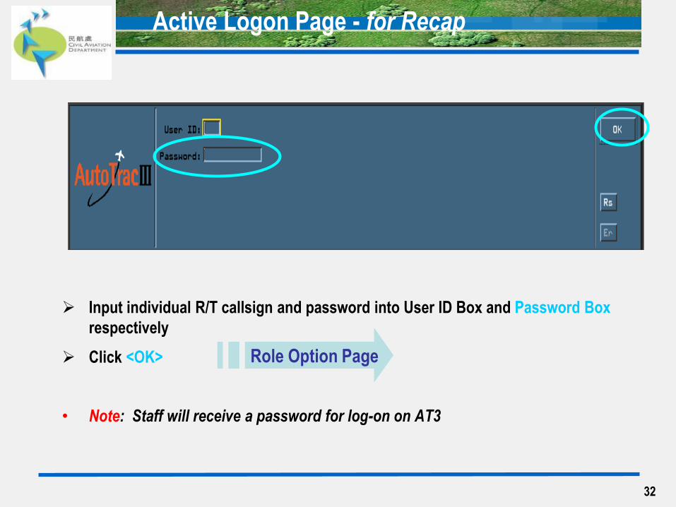
Active Logon Page - for Recap
Input individual R/T callsign and password into User ID Box and Password Box
respectively
Click <OK>
• Note: Staff will receive a password for log-on on AT3
Role Option Page
33
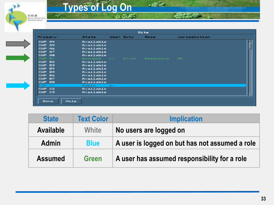
Types of Log On
State Text Color Implication
Available White No users are logged on
Admin Blue A user is logged on but has not assumed a role
Assumed Green A user has assumed responsibility for a role

34
Points to Note:
Operator is required to attain Assumed Log On
The accessibility of some functions is limited with Administrative Log On. For example, unable to obtain Electronic Flight Strip <EFS>
Select <Site_> to display the status of log on, which is invoked at Reconfiguration Base Page. Details will be discussed in Chapter 5
Note: <Multi-CJS> will not be used by AC
General Notes of Log On Process
35
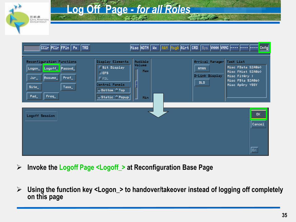
Log Off Page - for all Roles
Invoke the Logoff Page <Logoff_> at Reconfiguration Base Page
Using the function key <Logon_> to handover/takeover instead of logging off completely on this page
Primary Control Panel (PCP) - AC
Secondary Control Panel (SCP) – AC
System Summary Window
Confirmation Buttons
36
AT3 Common Used Panel
37
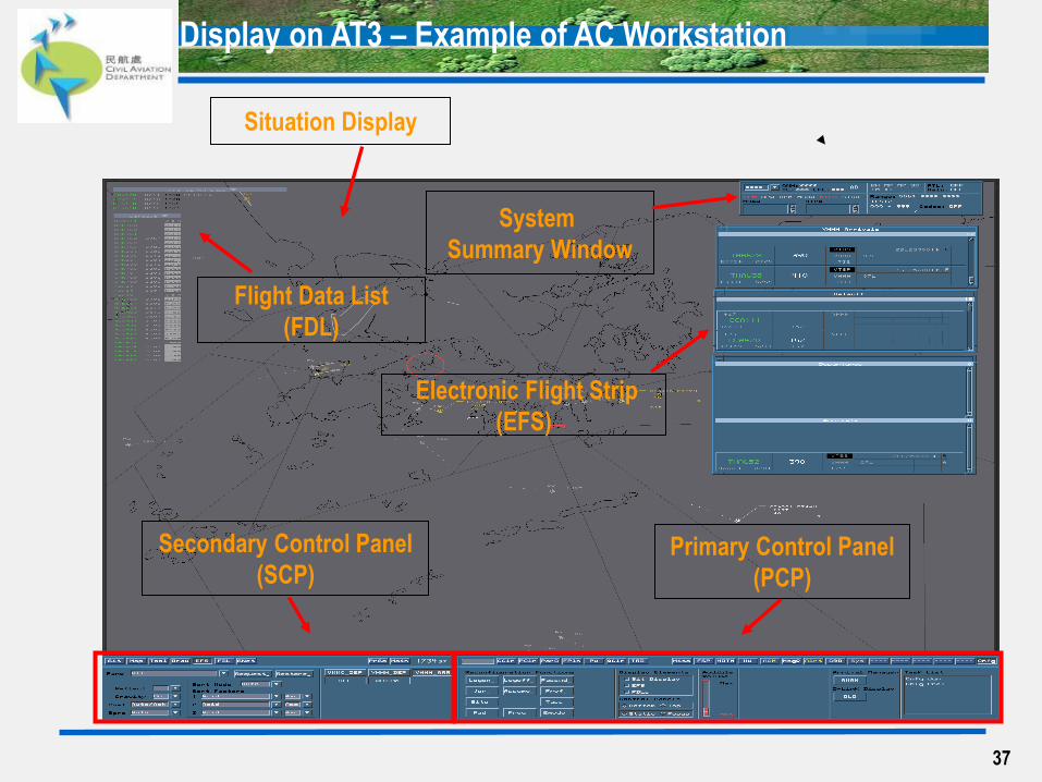
Secondary Control Panel
(SCP)
System
Summary Window
Electronic Flight Strip
(EFS)
Flight Data List
(FDL)
Primary Control Panel
(PCP)
Display on AT3 – Example of AC Workstation
Situation Display
38
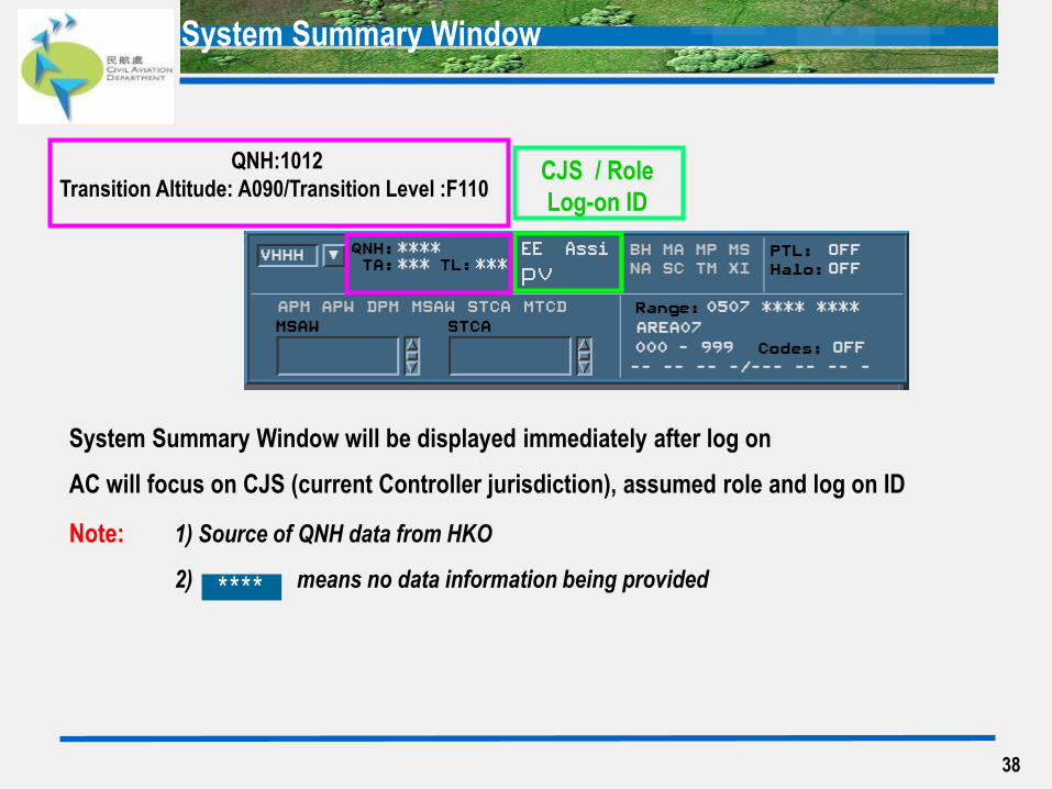
CJS / Role
Log-on ID
QNH:1012
Transition Altitude: A090/Transition Level :F110
System Summary Window will be displayed immediately after log on
AC will focus on CJS (current Controller jurisdiction), assumed role and log on ID
Note: 1) Source of QNH data from HKO
2) means no data information being provided
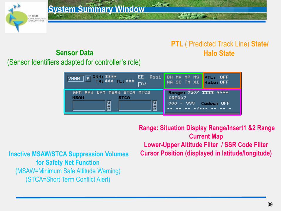
System Summary Window
****
39
Inactive MSAW/STCA Suppression Volumes
for Safety Net Function
(MSAW=Minimum Safe Altitude Warning)
(STCA=Short Term Conflict Alert)
Sensor Data
(Sensor Identifiers adapted for controller’s role)
PTL ( Predicted Track Line) State/
Halo State
Range: Situation Display Range/Insert1 &2 Range
Current Map
Lower-Upper Altitude Filter / SSR Code Filter
Cursor Position (displayed in latitude/longitude)
System Summary Window
40
Primary and Secondary Control Panel

41
Primary Control Panel (PCP) Header
Primary Control Panel (PCP) – Assistant Role
<CClr>, <PClr>, <FPln>, <TRD>, <Misc>, <MsgQ>, <Alrt>, <Sys> & <Cnfg> functions
would be useful to ACs
42
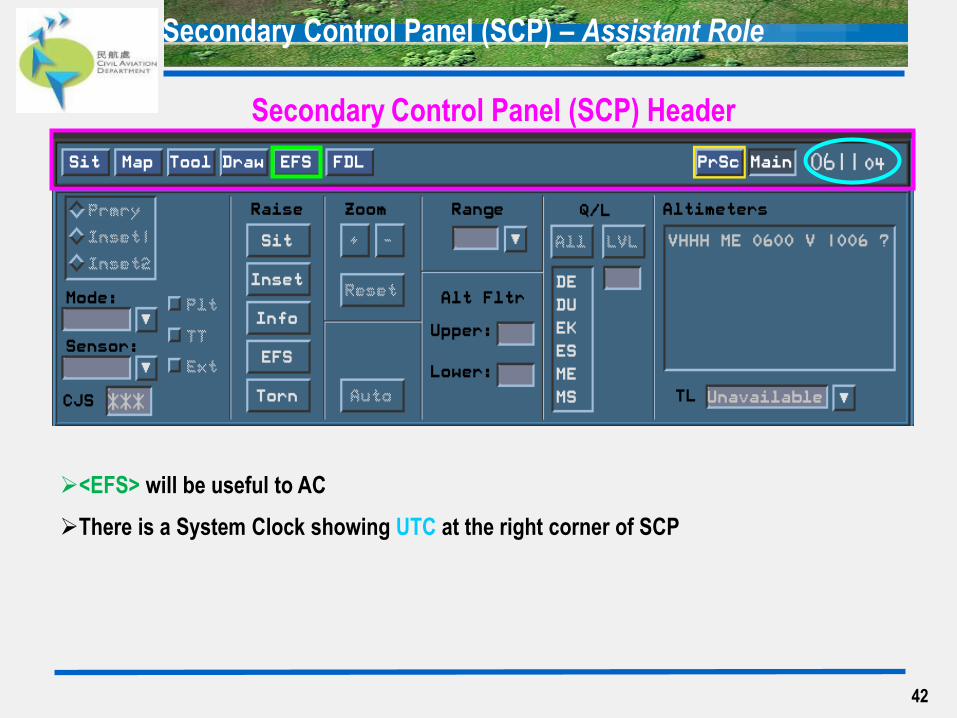
Secondary Control Panel (SCP) – Assistant Role
<EFS> will be useful to AC
There is a System Clock showing UTC at the right corner of SCP
Secondary Control Panel (SCP) Header
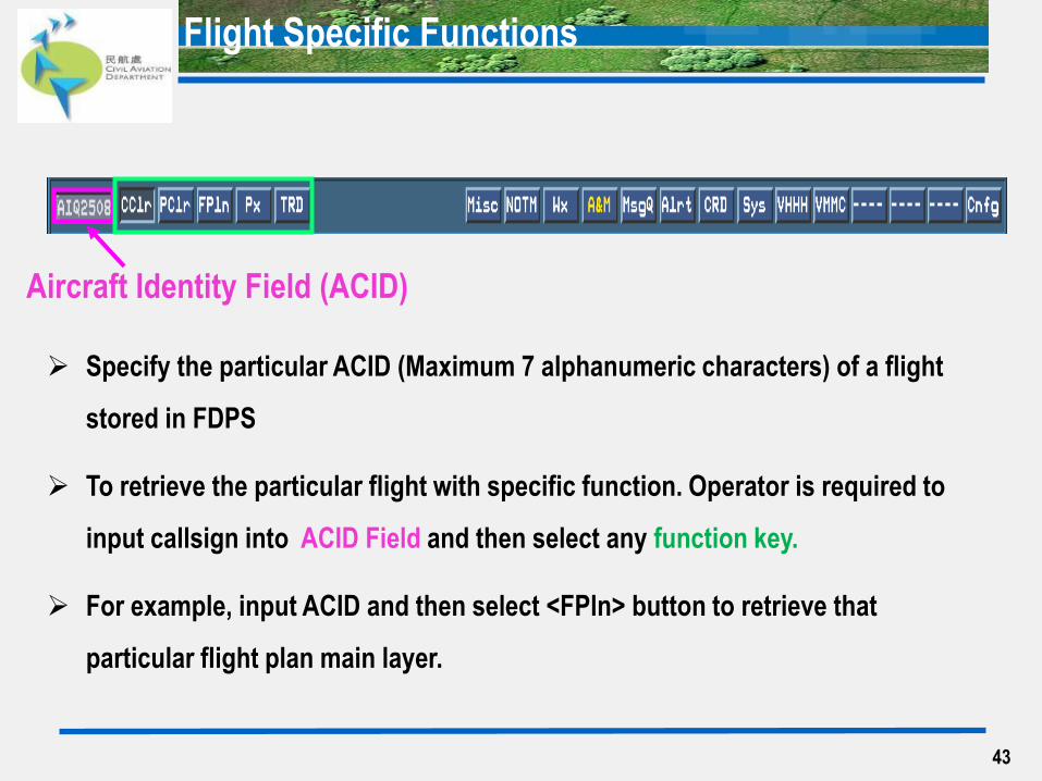
Flight Specific Functions
43
Aircraft Identity Field (ACID)
Specify the particular ACID (Maximum 7 alphanumeric characters) of a flight
stored in FDPS
To retrieve the particular flight with specific function. Operator is required to
input callsign into ACID Field and then select any function key.
For example, input ACID and then select <FPln> button to retrieve that
particular flight plan main layer.
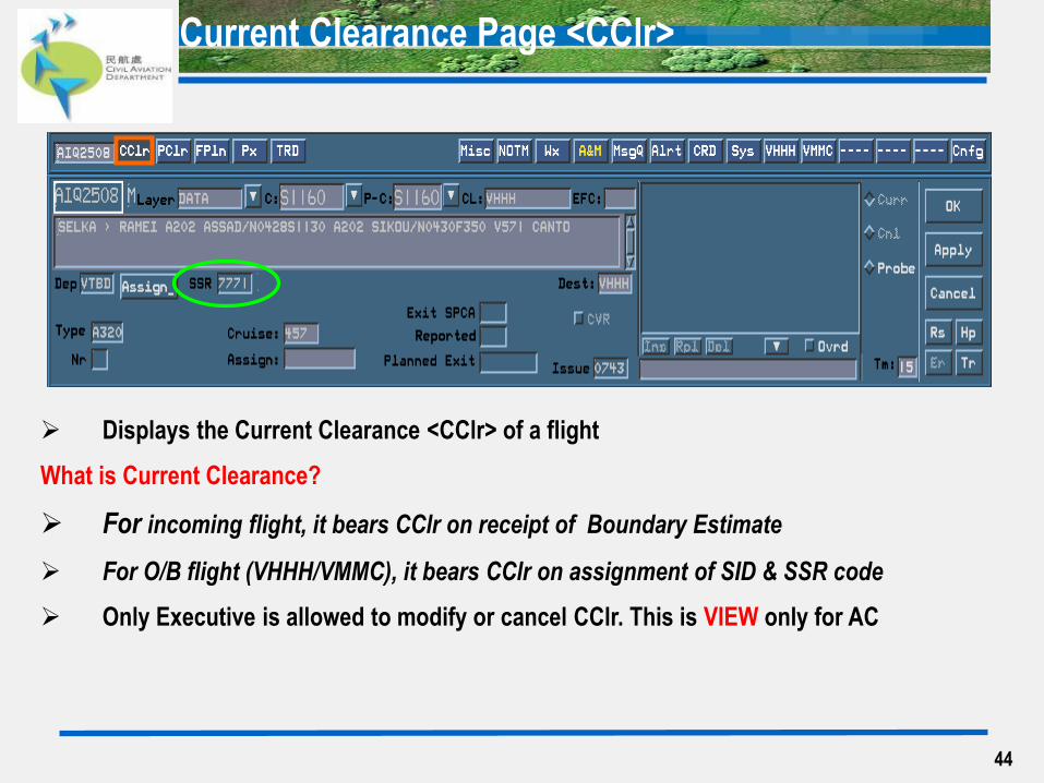
Current Clearance Page <CClr>
44
Displays the Current Clearance <CClr> of a flight
What is Current Clearance?
For incoming flight, it bears CClr on receipt of Boundary Estimate
For O/B flight (VHHH/VMMC), it bears CClr on assignment of SID & SSR code
Only Executive is allowed to modify or cancel CClr. This is VIEW only for AC

45
Current Clearance Page <CClr>
Total 8 Layers
‘DATA’ is the default layer
Incoming Flight plan without boundary Estimate or
Outgoing flight plan does not bear SSR & SID will not
show CClr
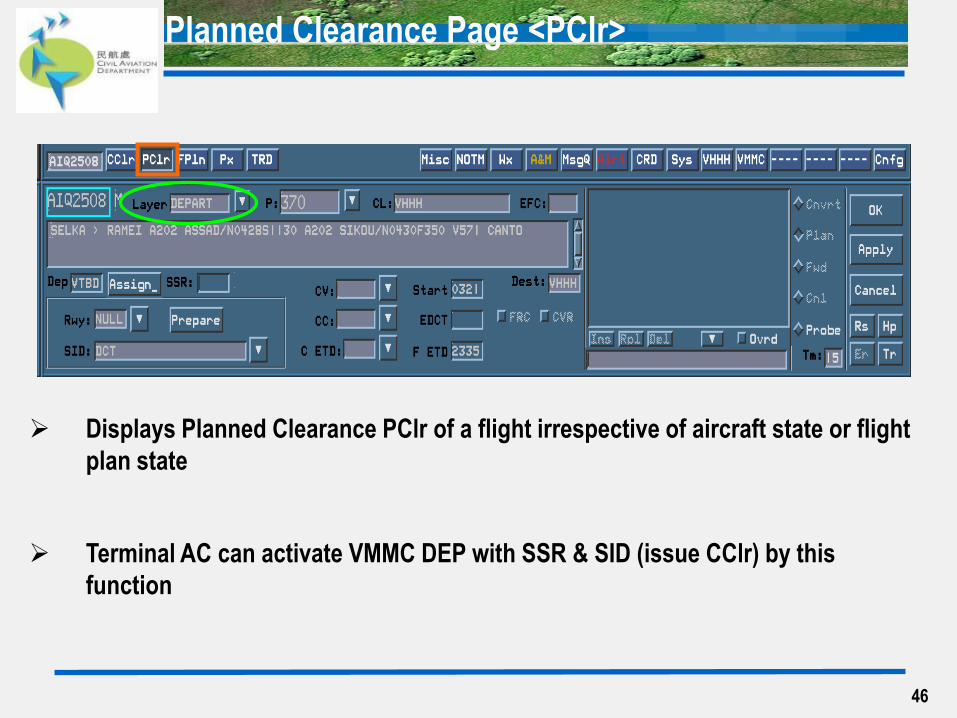
Planned Clearance Page <PClr>
46
Displays Planned Clearance PClr of a flight irrespective of aircraft state or flight
plan state
Terminal AC can activate VMMC DEP with SSR & SID (issue CClr) by this
function

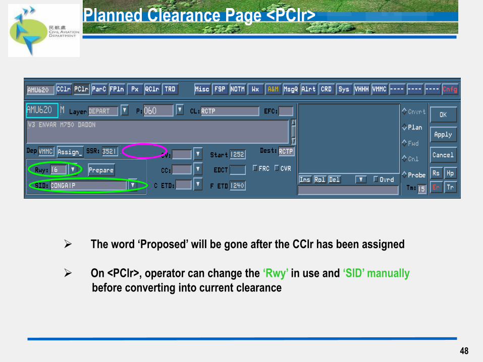
Planned Clearance Page <PClr>
47
The SSR code of FPL in item 7/ will be abstracted onto <PClr> and the word ‘Proposed’
is stated when CClr is not issued
Planned Clearance Page <PClr>
48
The word ‘Proposed’ will be gone after the CClr has been assigned
On <PClr>, operator can change the ‘Rwy’ in use and ‘SID’ manually
before converting into current clearance
49
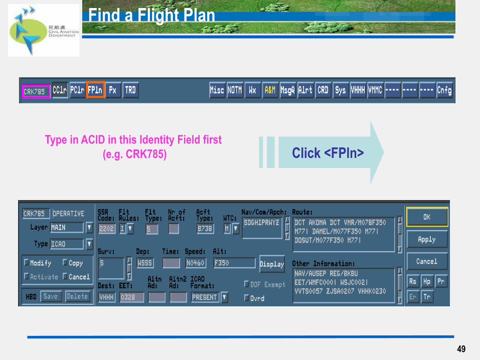
Find a Flight Plan
Type in ACID in this Identity Field first
(e.g. CRK785) Click <FPln>
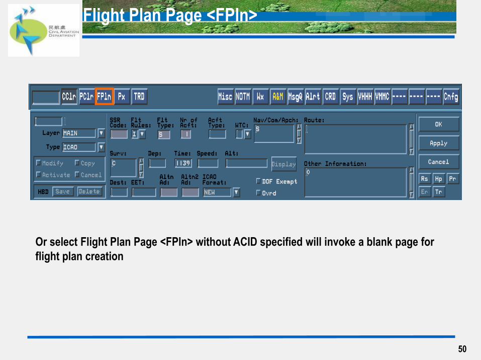
Flight Plan Page <FPln>
50
Or select Flight Plan Page <FPln> without ACID specified will invoke a blank page for
flight plan creation

Tabular Route Display Page <TRD>
51
This page displays fixes along route and associated estimates of a particular flight
There are 3 Profiles for selection:
- Expected (associated estimates generated by the system according the aircraft performance)
- Planned (only available after a flight with Planned Clearance)
- Current (only available after a flight with Current Clearance)
AC will use the Expected Profile to view the associated estimates
AC can use either left or right hand side column
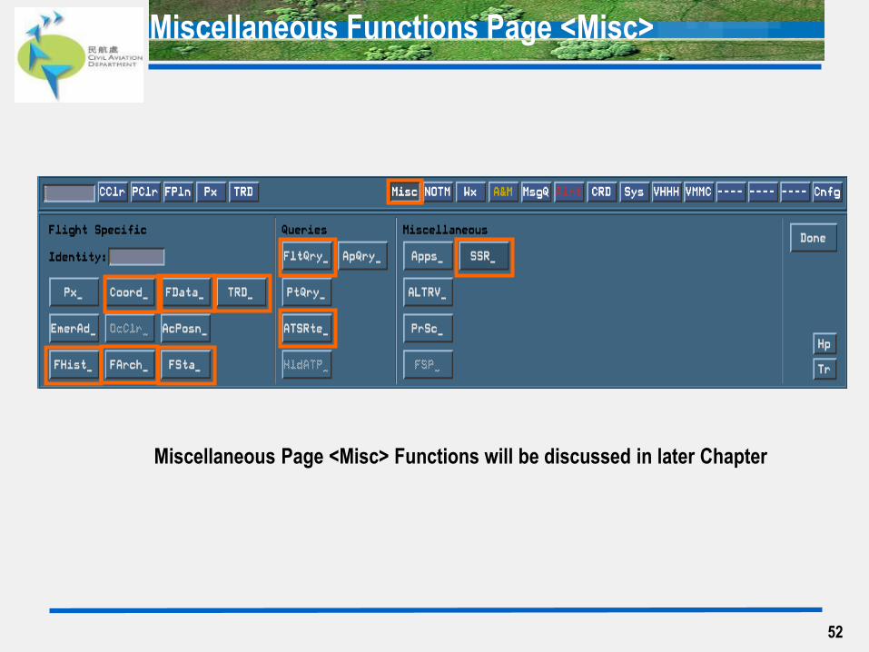
Miscellaneous Functions Page <Misc>
52
Miscellaneous Page <Misc> Functions will be discussed in later Chapter
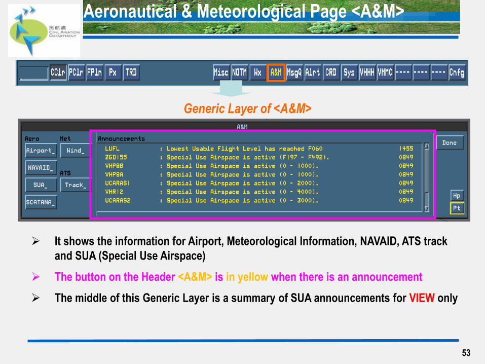
Aeronautical & Meteorological Page <A&M>
53
Generic Layer of <A&M>
It shows the information for Airport, Meteorological Information, NAVAID, ATS track
and SUA (Special Use Airspace)
The button on the Header <A&M> is in yellow when there is an announcement
The middle of this Generic Layer is a summary of SUA announcements for VIEW only
54
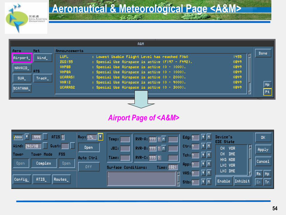
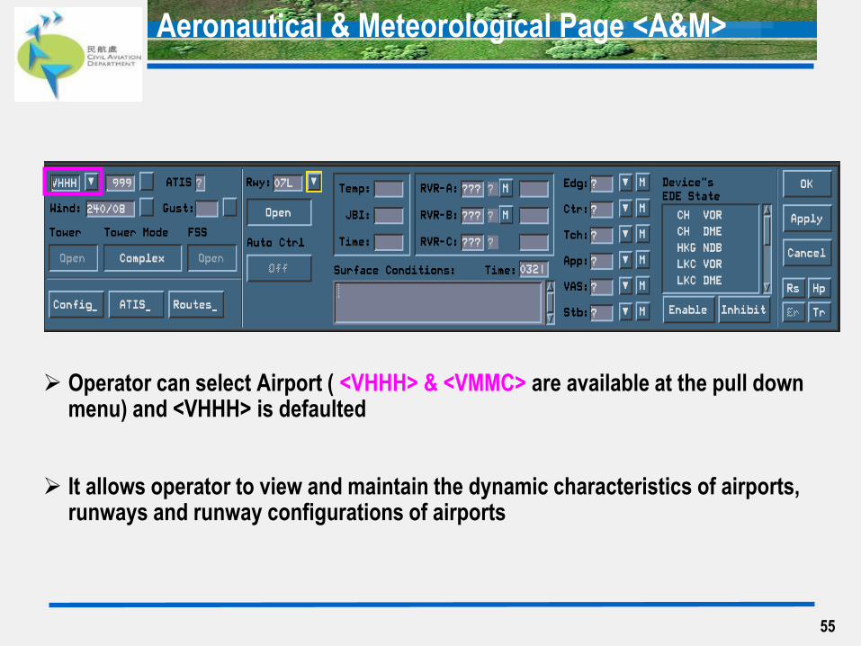
Airport Page of <A&M>
Aeronautical & Meteorological Page <A&M>
55
Operator can select Airport ( <VHHH> & <VMMC> are available at the pull down menu) and <VHHH> is defaulted
It allows operator to view and maintain the dynamic characteristics of airports, runways and runway configurations of airports
Aeronautical & Meteorological Page <A&M>
56
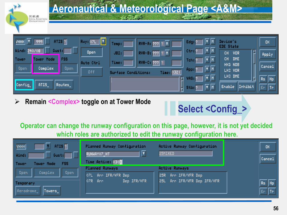
Remain <Complex> toggle on at Tower Mode
Select <Config_>
Operator can change the runway configuration on this page, however, it is not yet decided
which roles are authorized to edit the runway configuration here.
Aeronautical & Meteorological Page <A&M>
Message Queue Page <MsgQ>
57
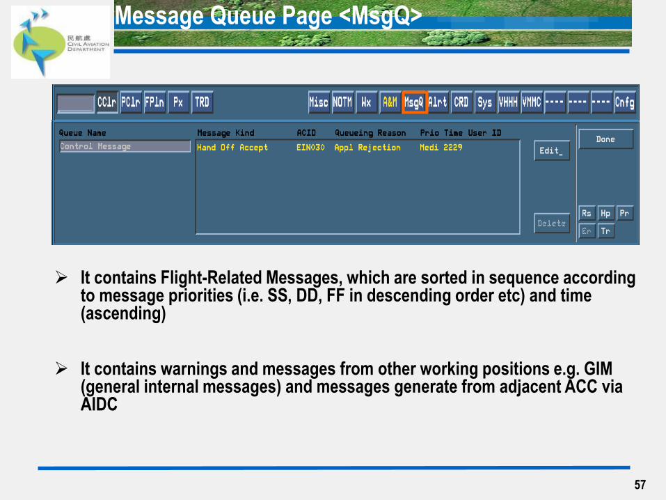
It contains Flight-Related Messages, which are sorted in sequence according to message priorities (i.e. SS, DD, FF in descending order etc) and time (ascending)
It contains warnings and messages from other working positions e.g. GIM (general internal messages) and messages generate from adjacent ACC via AIDC
Message Queue Page <MsgQ>
58
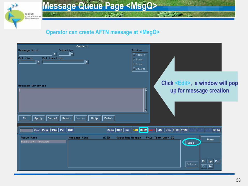
Click <Edit>, a window will pop
up for message creation
Operator can create AFTN message at <MsgQ>
Message Queue Page <MsgQ>
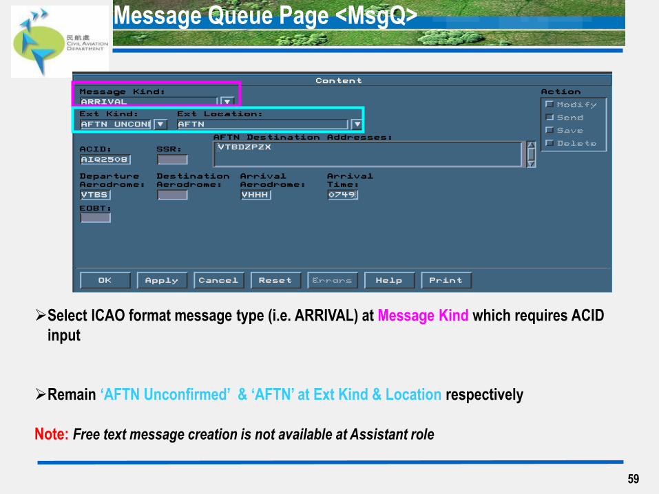
59
Select ICAO format message type (i.e. ARRIVAL) at Message Kind which requires ACID
input
Remain ‘AFTN Unconfirmed’ & ‘AFTN’ at Ext Kind & Location respectively
Note: Free text message creation is not available at Assistant role

Flight-Related Announcements Page <Alrt>
60
This page contains flight-related announcements which may require actions
The colour shows the degree of criticality; messages are in descending order of
message priority, and ascending order of time. at the top followed by
and then
Announcement is acknowledged once it is selected by clicking B1 except those Alert
in red
ACID of that message will be displayed at ACID Box once it is selected.
Alerts in red
Warnings in yellow Information Messages in grey
System-Related Announcements Page <Sys>
61
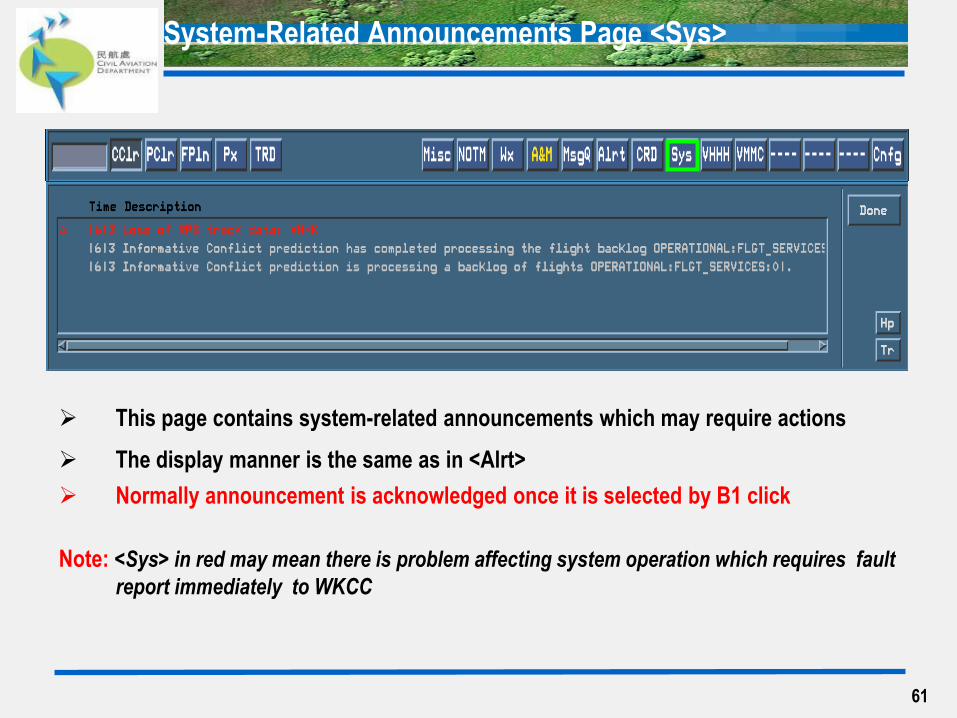
This page contains system-related announcements which may require actions
The display manner is the same as in <Alrt>
Normally announcement is acknowledged once it is selected by B1 click
Note: <Sys> in red may mean there is problem affecting system operation which requires fault
report immediately to WKCC
Reconfiguration Base Page <Cnfg>
62
63
Reconfiguration Base Page
63
64
Contents
Reconfiguration Base Page <Cnfg> – for Assistant Role
How to Invoke <Cnfg>
Active Log On Page <Logon_>
Role Option Page <Jur_>
Status Display Page <Site_>
Operational Notepad Page <Pad_>
Log Off Page <Logoff_>
Assume Role Page <Assume_>
Change Password Page <Passwd_>
Change Preference Page <Pref_>
Display Element
Control Panel
Audible Volume
Task List
64
Reconfiguration Base Page <Cnfg>
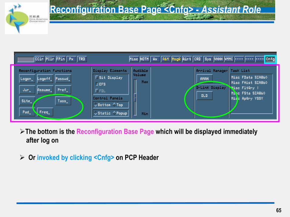
Reconfiguration Base Page <Cnfg> - Assistant Role
65
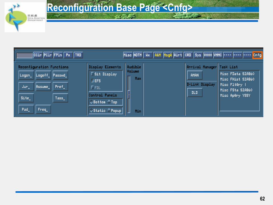
The bottom is the Reconfiguration Base Page which will be displayed immediately
after log on
Or invoked by clicking <Cnfg> on PCP Header
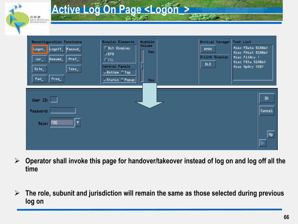
Active Log On Page <Logon_>
Operator shall invoke this page for handover/takeover instead of log on and log off all the time
The role, subunit and jurisdiction will remain the same as those selected during previous log on
66

Role Option Page <Jur_>
67
Operator can change his/her jurisdiction on this page
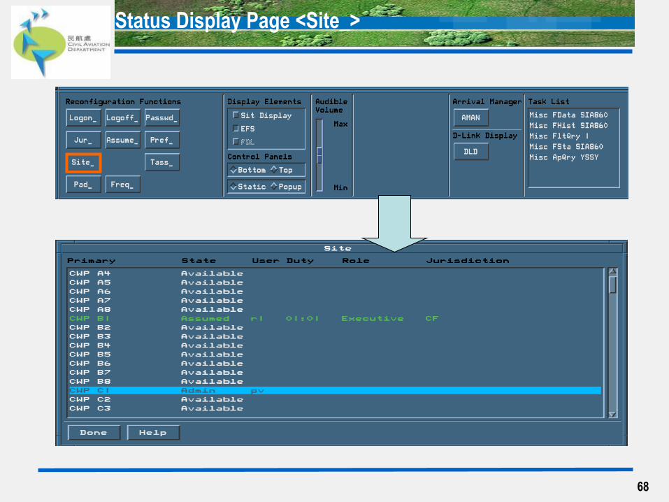
Status Display Page <Site_>
68
69
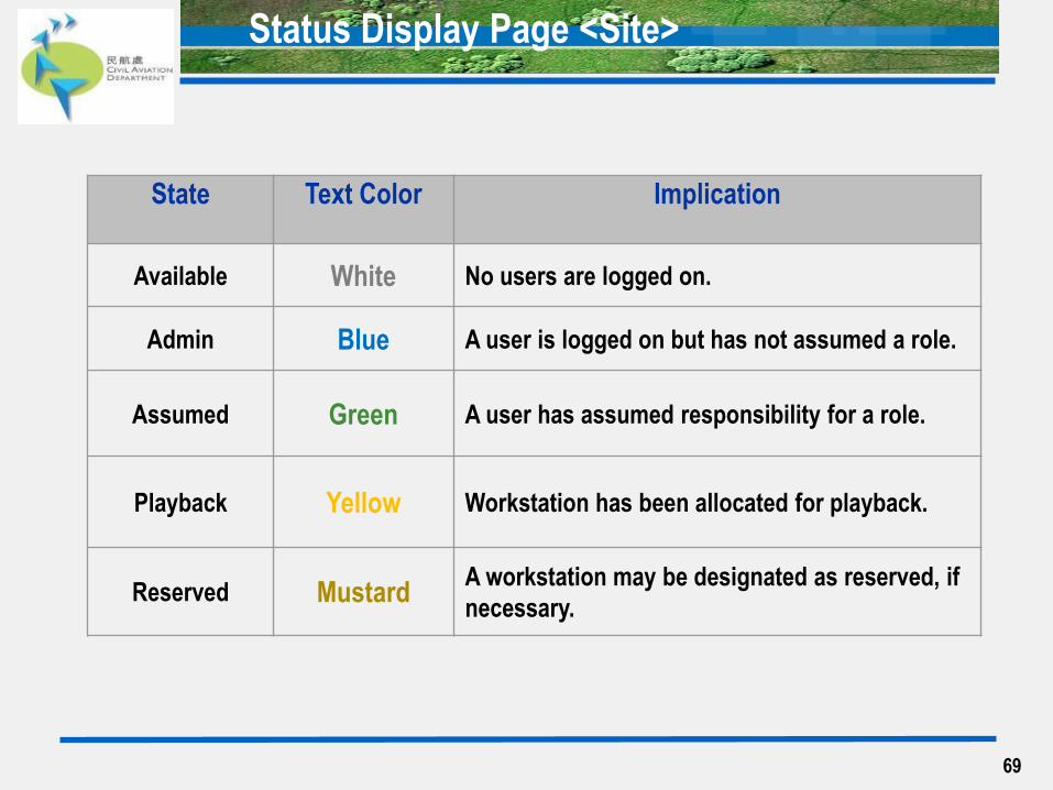
Status Display Page <Site>
State Text Color Implication
Available White No users are logged on.
Admin Blue A user is logged on but has not assumed a role.
Assumed Green A user has assumed responsibility for a role.
Playback Yellow Workstation has been allocated for playback.
Reserved Mustard A workstation may be designated as reserved, if
necessary.
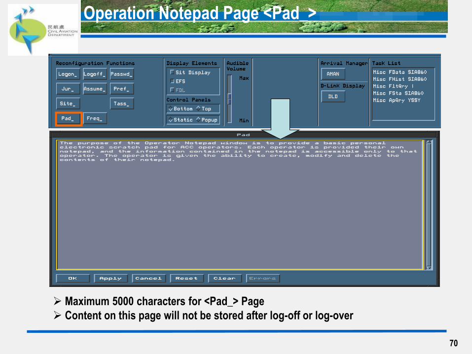
Operation Notepad Page <Pad_>
70
Maximum 5000 characters for <Pad_> Page
Content on this page will not be stored after log-off or log-over
71
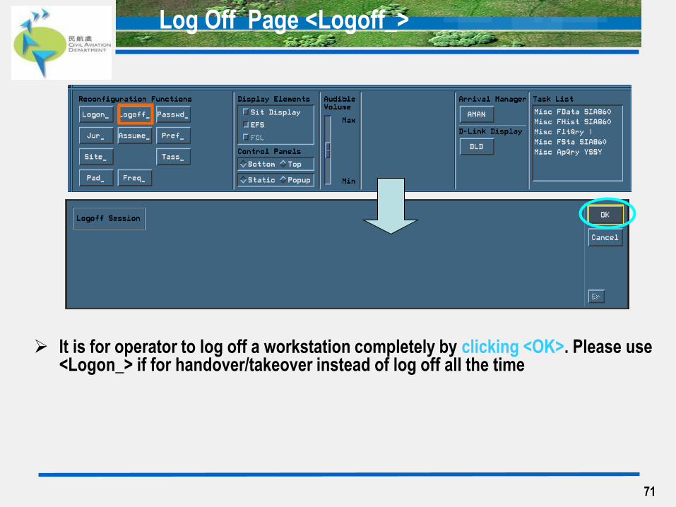
Log Off Page <Logoff_>
It is for operator to log off a workstation completely by clicking <OK>. Please use <Logon_> if for handover/takeover instead of log off all the time

72
Assume Role Page <Assume_>
If operator only has an Administrative Log On at the beginning,
he/she can complete an Assumed Log On here by clicking <OK>
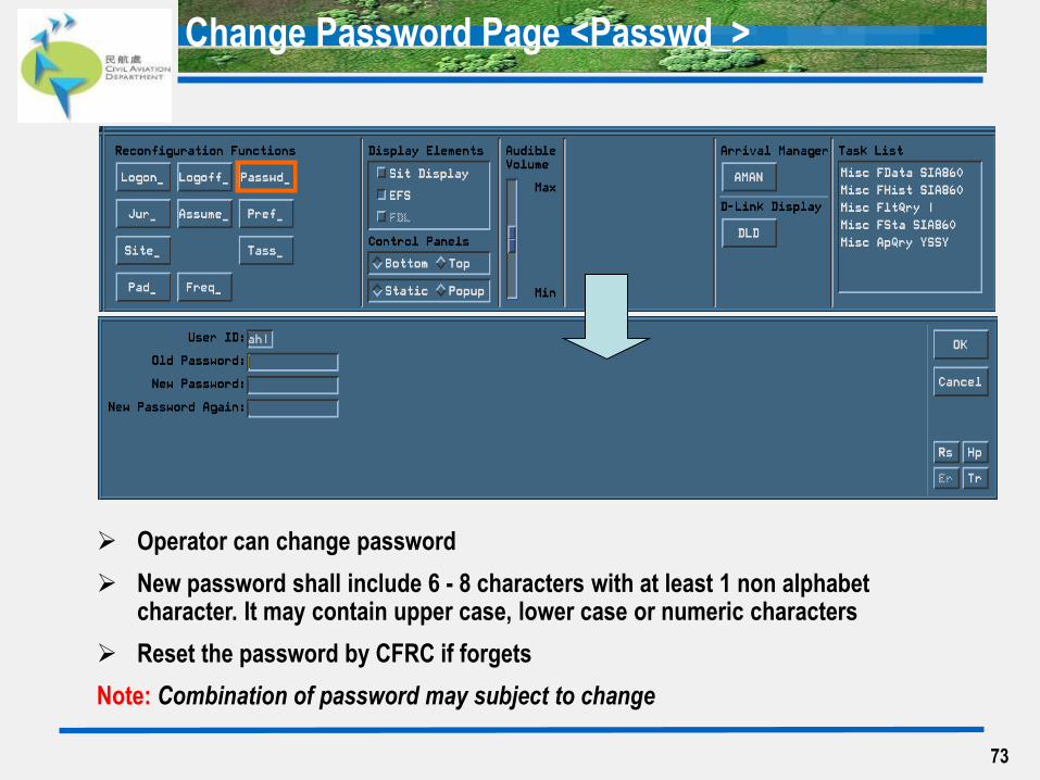
Change Password Page <Passwd_>
73
Operator can change password
New password shall include 6 - 8 characters with at least 1 non alphabet character. It may contain upper case, lower case or numeric characters
Reset the password by CFRC if forgets
Note: Combination of password may subject to change
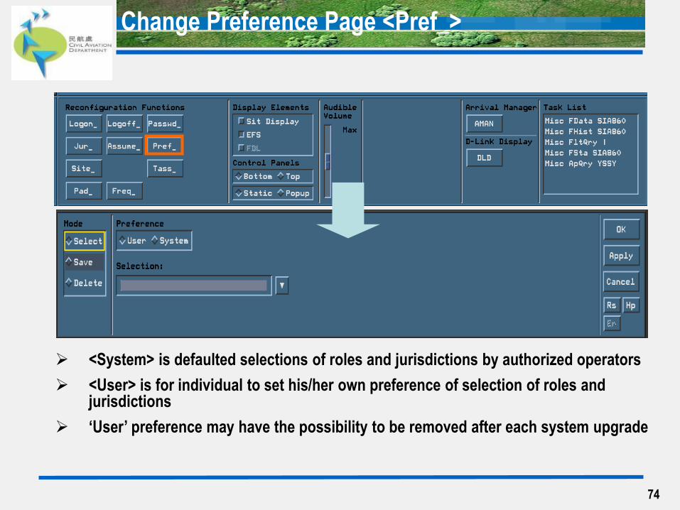
Change Preference Page <Pref_>
74
<System> is defaulted selections of roles and jurisdictions by authorized operators
<User> is for individual to set his/her own preference of selection of roles and jurisdictions
‘User’ preference may have the possibility to be removed after each system upgrade
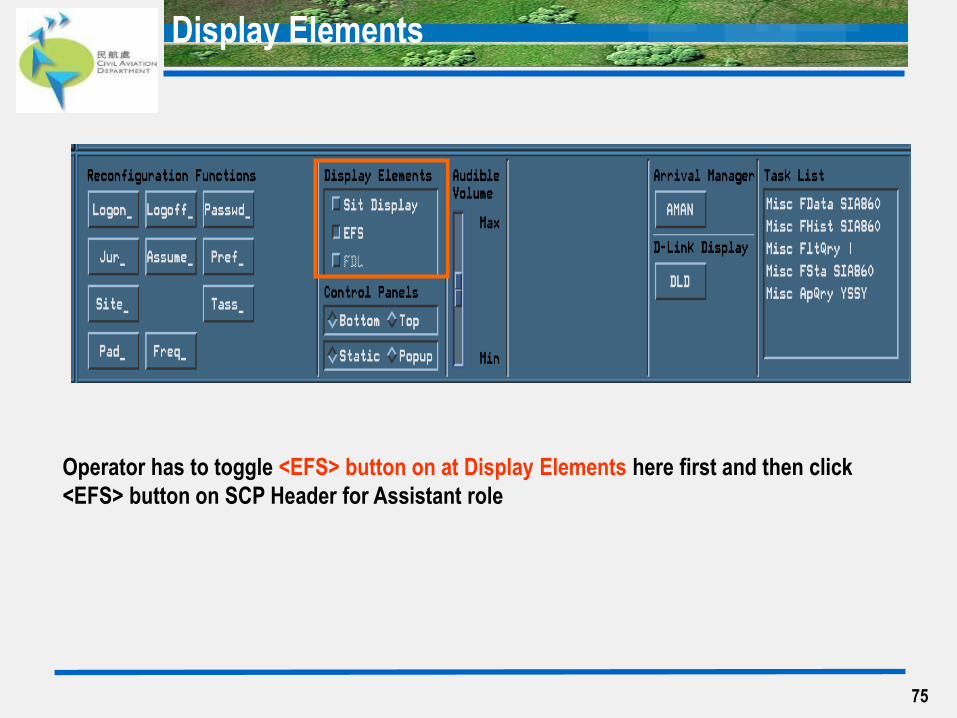
Display Elements
75
Operator has to toggle <EFS> button on at Display Elements here first and then click
<EFS> button on SCP Header for Assistant role

Display Elements - <Control Panels>
76
These buttons are to set preference of the display of Control Panel
<Bottom> and <Top> are to adjust the location of the Control Panel either at the top
of the Display or the bottom of the Display (‘Bottom’ is defaulted)
<Static> and <Popup> are to adjust the location of the Control Panel relatively to the Header (‘Static’ is defaulted)
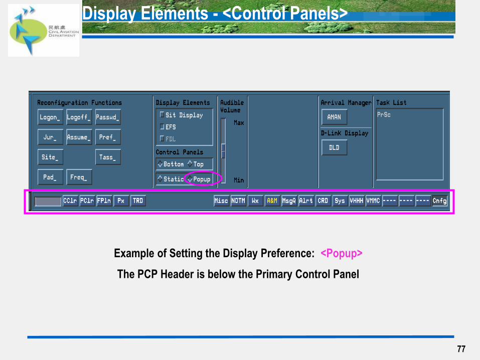
Display Elements - <Control Panels>
Example of Setting the Display Preference: <Popup>
The PCP Header is below the Primary Control Panel
77
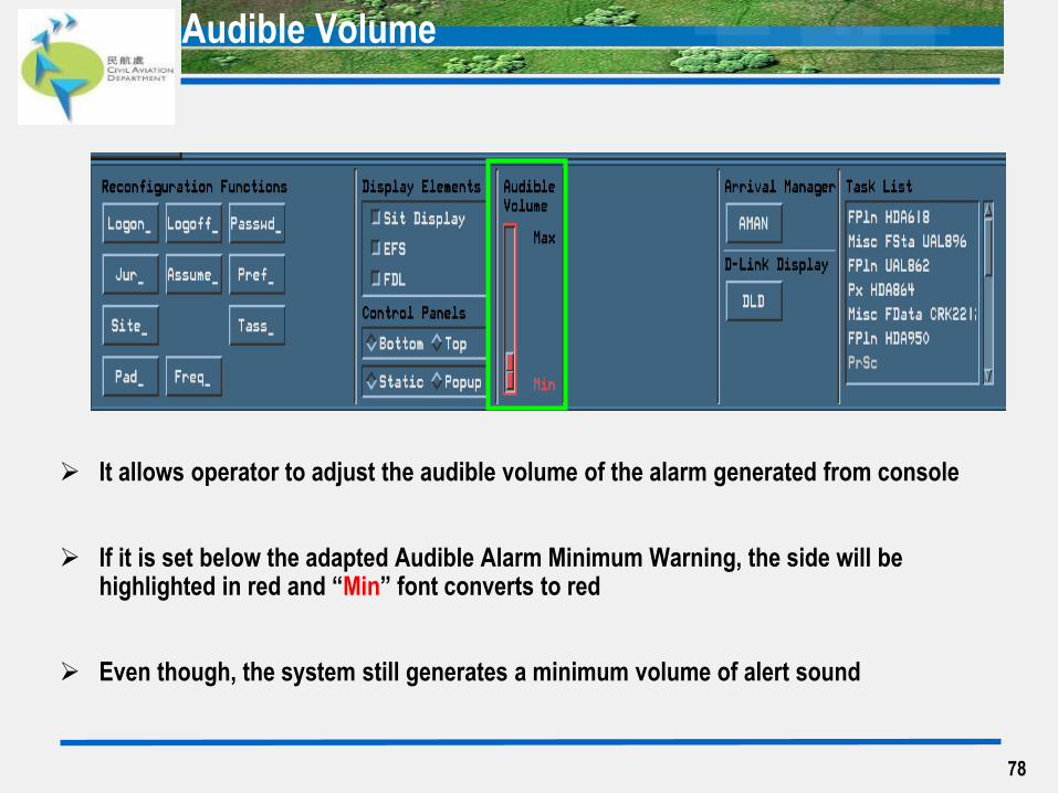
Audible Volume
It allows operator to adjust the audible volume of the alarm generated from console
If it is set below the adapted Audible Alarm Minimum Warning, the side will be highlighted in red and “Min” font converts to red
Even though, the system still generates a minimum volume of alert sound
78
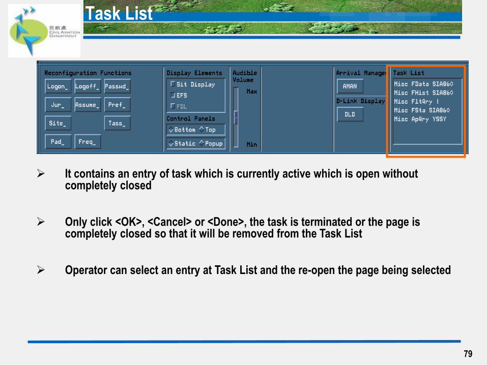
Task List
79
It contains an entry of task which is currently active which is open without completely closed
Only click <OK>, <Cancel> or <Done>, the task is terminated or the page is completely closed so that it will be removed from the Task List
Operator can select an entry at Task List and the re-open the page being selected
Task List
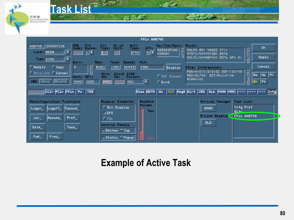
Example of Active Task
80
Task List
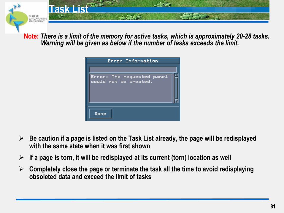
Be caution if a page is listed on the Task List already, the page will be redisplayed with the same state when it was first shown
If a page is torn, it will be redisplayed at its current (torn) location as well
Completely close the page or terminate the task all the time to avoid redisplaying obsoleted data and exceed the limit of tasks
81
Note: There is a limit of the memory for active tasks, which is approximately 20-28 tasks. Warning will be given as below if the number of tasks exceeds the limit.

82
Flight Plan Page
83
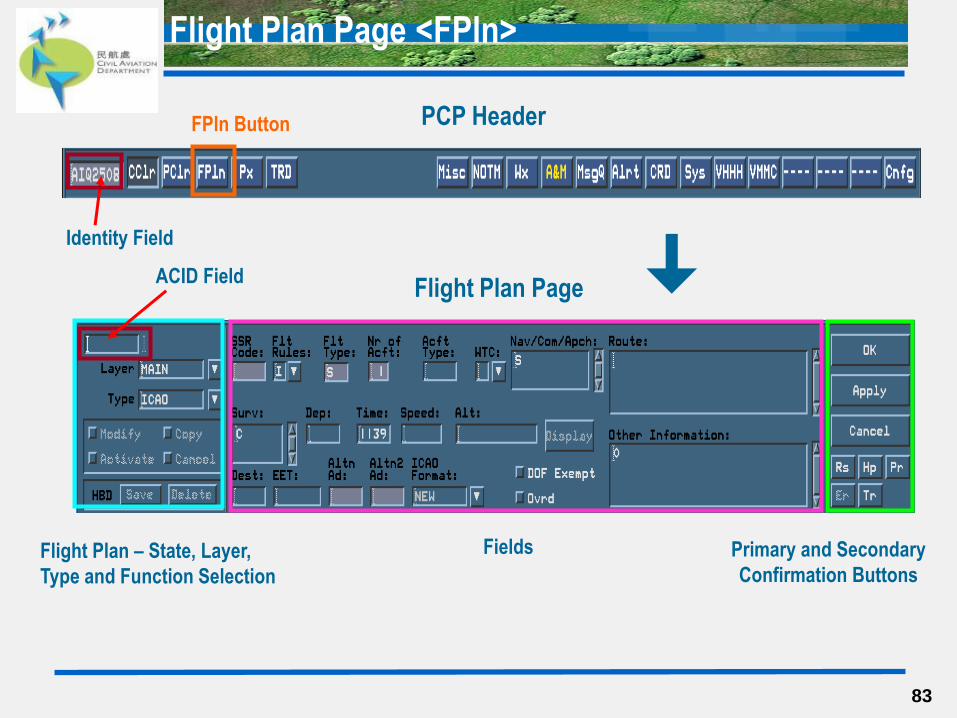
Flight Plan Page <FPln>
PCP Header
Flight Plan Page
FPln Button
Identity Field
Fields Primary and Secondary
Confirmation Buttons Flight Plan – State, Layer,
Type and Function Selection
ACID Field
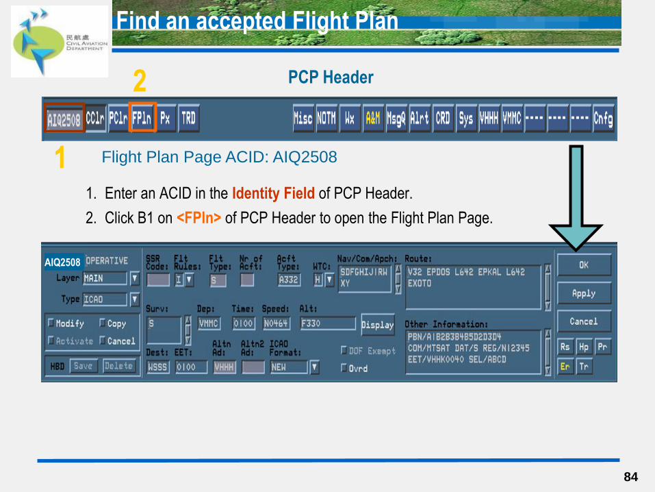
1. Enter an ACID in the Identity Field of PCP Header.
2. Click B1 on <FPln> of PCP Header to open the Flight Plan Page.
84
PCP Header
Flight Plan Page ACID: AIQ2508
2
Find an accepted Flight Plan
AIQ2508
1
Flight Plan Page - States / Layers / Types
85
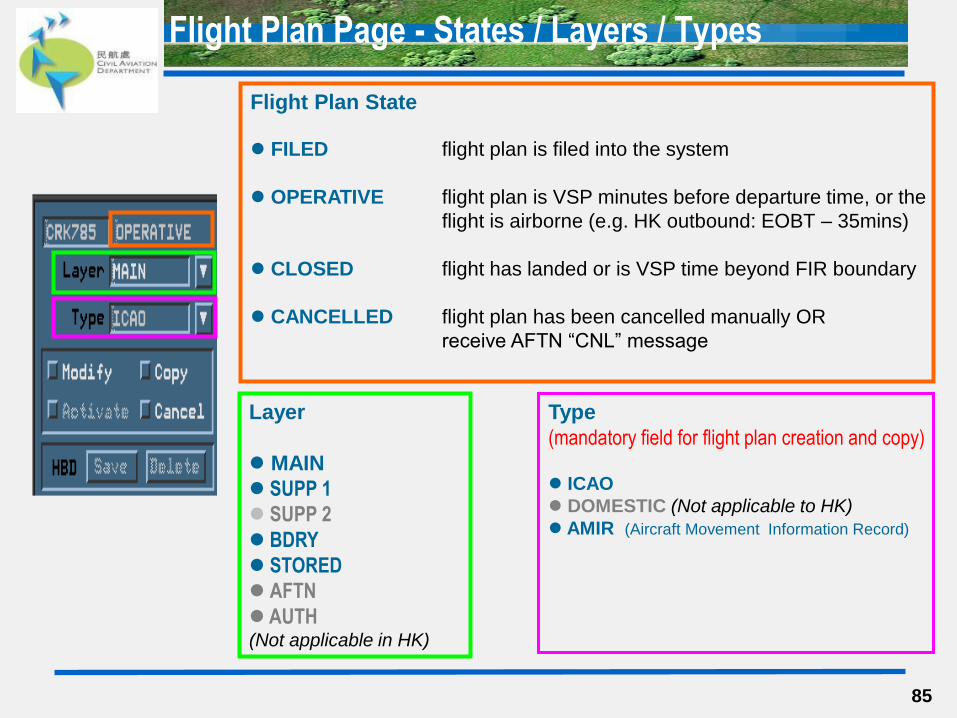
Flight Plan State
FILED flight plan is filed into the system
OPERATIVE flight plan is VSP minutes before departure time, or the
flight is airborne (e.g. HK outbound: EOBT – 35mins)
CLOSED flight has landed or is VSP time beyond FIR boundary
CANCELLED flight plan has been cancelled manually OR
receive AFTN “CNL” message
Layer
MAIN
SUPP 1
SUPP 2
BDRY
STORED
AFTN
AUTH (Not applicable in HK)
Type
(mandatory field for flight plan creation and copy)
ICAO
DOMESTIC (Not applicable to HK)
AMIR (Aircraft Movement Information Record)
Flight Plan Page - Main & Boundary Layers
86
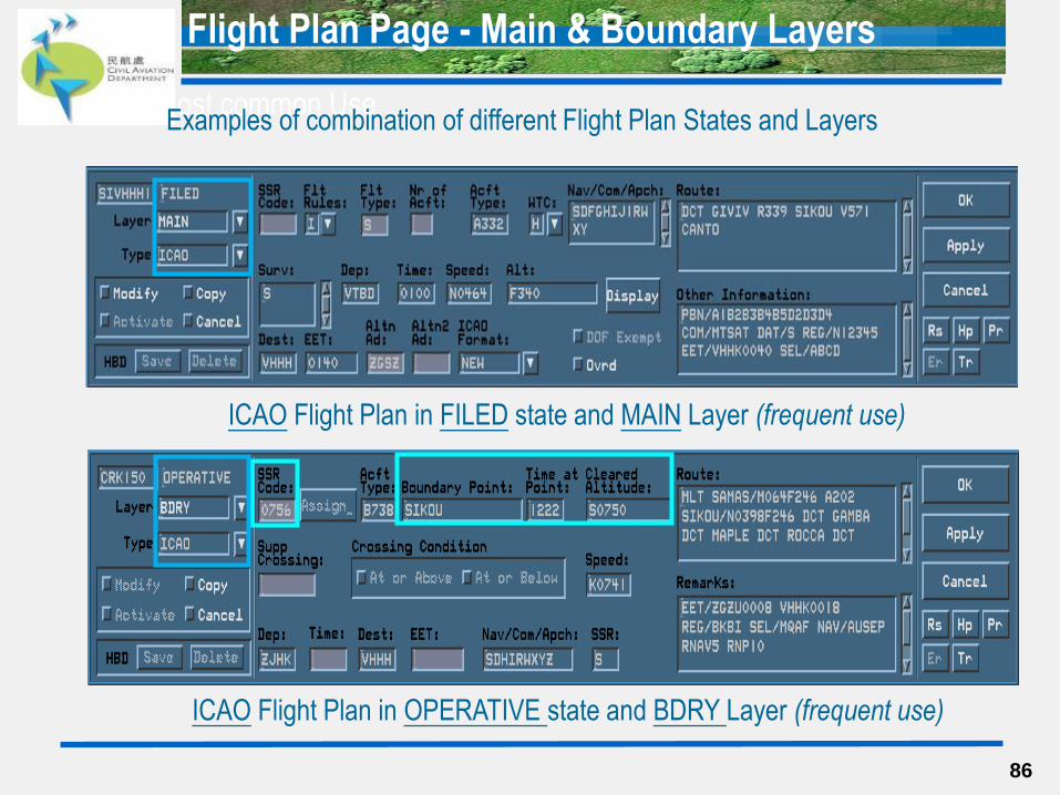
ICAO Flight Plan in FILED state and MAIN Layer (frequent use)
ICAO Flight Plan in OPERATIVE state and BDRY Layer (frequent use)
Most common Use Examples of combination of different Flight Plan States and Layers
Flight Plan Page - Function Selection
87
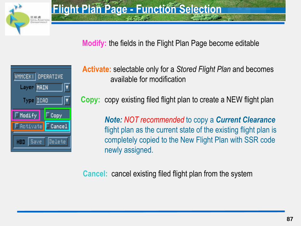
Cancel: cancel existing filed flight plan from the system
Copy: copy existing filed flight plan to create a NEW flight plan
Note: NOT recommended to copy a Current Clearance
flight plan as the current state of the existing flight plan is
completely copied to the New Flight Plan with SSR code
newly assigned.
Activate: selectable only for a Stored Flight Plan and becomes
available for modification
Modify: the fields in the Flight Plan Page become editable
88
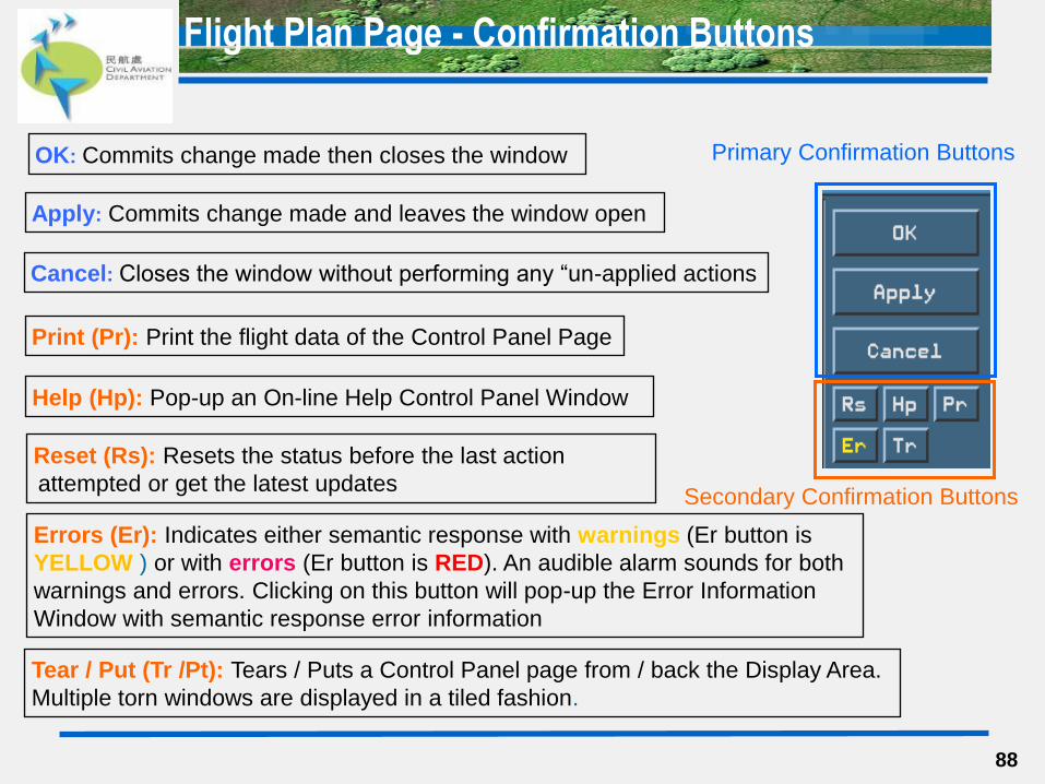
Flight Plan Page - Confirmation Buttons
Help (Hp): Pop-up an On-line Help Control Panel Window
Errors (Er): Indicates either semantic response with warnings (Er button is
YELLOW ) or with errors (Er button is RED). An audible alarm sounds for both
warnings and errors. Clicking on this button will pop-up the Error Information
Window with semantic response error information
Tear / Put (Tr /Pt): Tears / Puts a Control Panel page from / back the Display Area.
Multiple torn windows are displayed in a tiled fashion.
Print (Pr): Print the flight data of the Control Panel Page
Reset (Rs): Resets the status before the last action
attempted or get the latest updates Secondary Confirmation Buttons
OK: Commits change made then closes the window
Apply: Commits change made and leaves the window open
Cancel: Closes the window without performing any “un-applied actions
Primary Confirmation Buttons
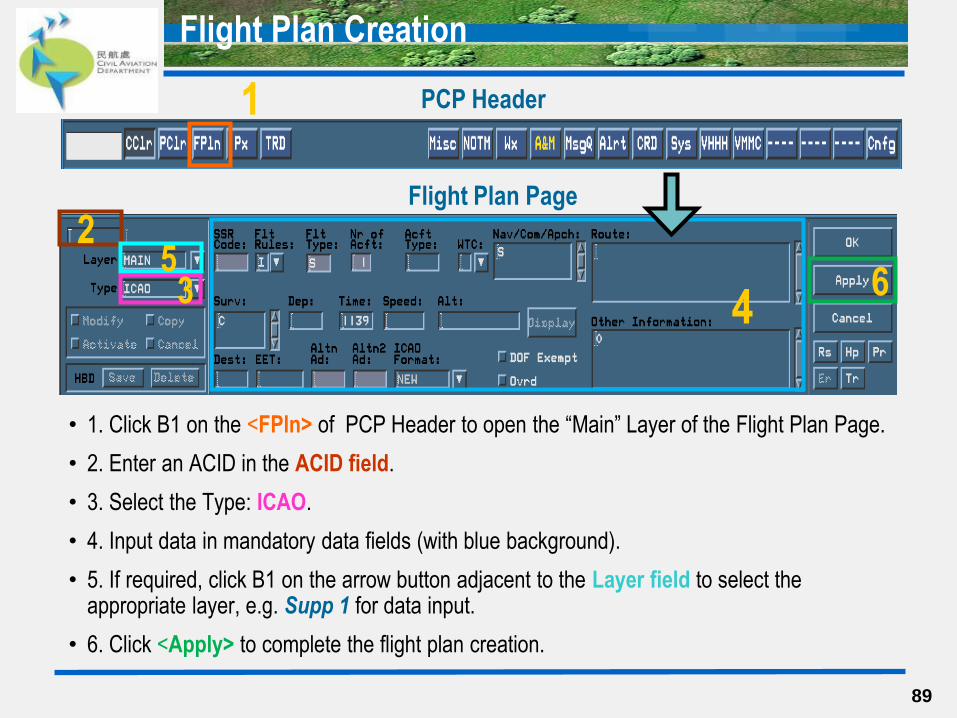
• 1. Click B1 on the <FPln> of PCP Header to open the “Main” Layer of the Flight Plan Page.
• 2. Enter an ACID in the ACID field.
• 3. Select the Type: ICAO.
• 4. Input data in mandatory data fields (with blue background).
• 5. If required, click B1 on the arrow button adjacent to the Layer field to select the appropriate layer, e.g. Supp 1 for data input.
• 6. Click <Apply> to complete the flight plan creation.
89
Flight Plan Creation
PCP Header
Flight Plan Page
1
2
3 4 6
5

• Data Fields with default value:
Flt Rules: I
Flt Types: S
Nr. of Acft: 1
Nav/Com/Apch: S
Surv: C
Time: Current System Time
Other Information: 0
90
Flight Plan Page - SARD Data Fields & Default Value
Data Fields in Main Layer
91
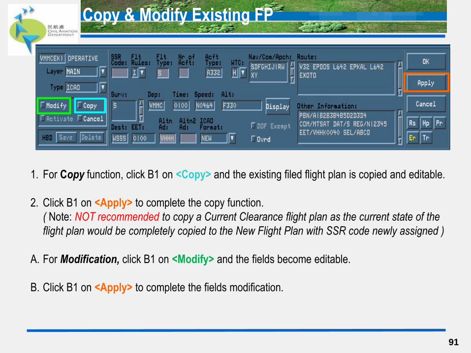
1. For Copy function, click B1 on <Copy> and the existing filed flight plan is copied and editable.
2. Click B1 on <Apply> to complete the copy function.
( Note: NOT recommended to copy a Current Clearance flight plan as the current state of the
flight plan would be completely copied to the New Flight Plan with SSR code newly assigned )
A. For Modification, click B1 on <Modify> and the fields become editable.
B. Click B1 on <Apply> to complete the fields modification.
Copy & Modify Existing FP
92
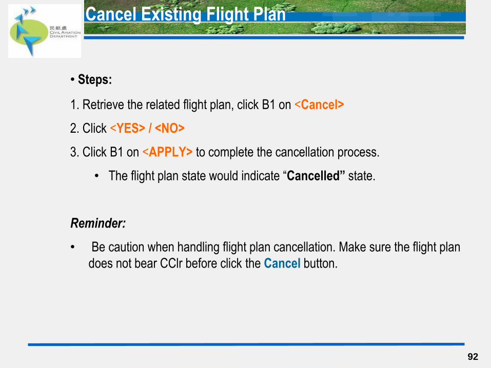
• Steps:
1. Retrieve the related flight plan, click B1 on <Cancel>
2. Click <YES> / <NO>
3. Click B1 on <APPLY> to complete the cancellation process.
• The flight plan state would indicate “Cancelled” state.
Reminder:
• Be caution when handling flight plan cancellation. Make sure the flight plan
does not bear CClr before click the Cancel button.
Cancel Existing Flight Plan
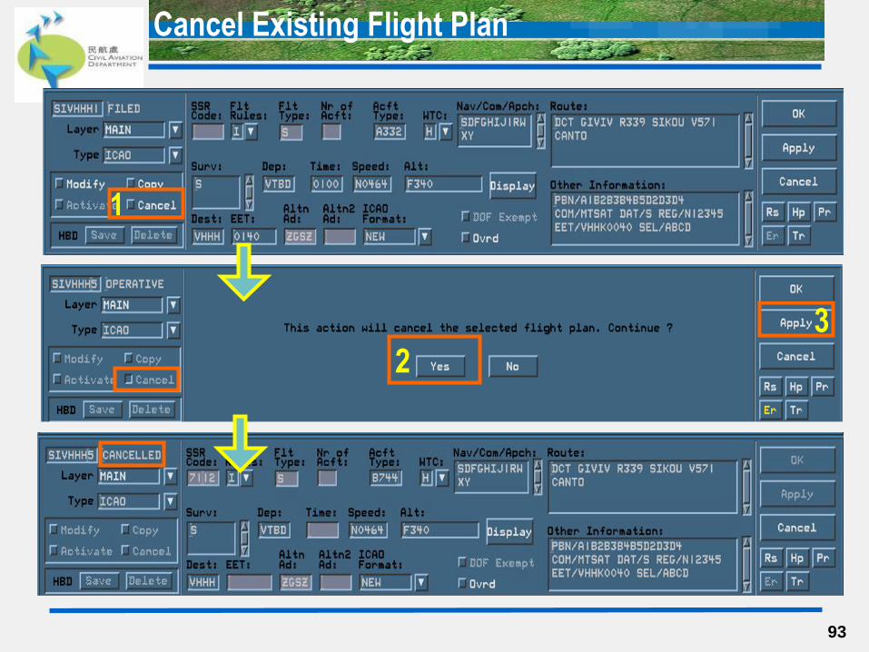
93
1
2
3
Cancel Existing Flight Plan
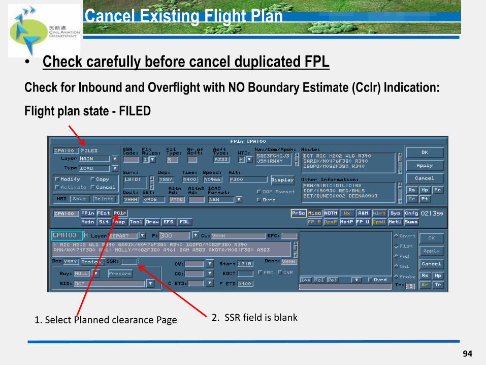
• Check carefully before cancel duplicated FPL
Check for Inbound and Overflight with NO Boundary Estimate (Cclr) Indication:
Flight plan state - FILED
94
1. Select Planned clearance Page 2. SSR field is blank
Cancel Existing Flight Plan
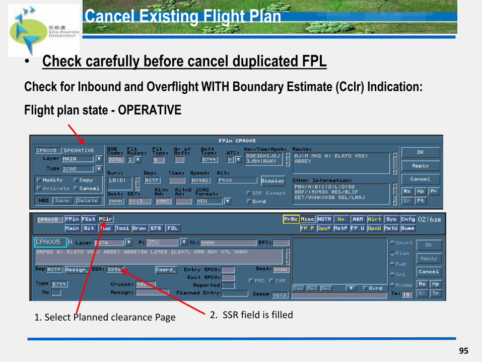
• Check carefully before cancel duplicated FPL
Check for Inbound and Overflight WITH Boundary Estimate (Cclr) Indication:
Flight plan state - OPERATIVE
95
1. Select Planned clearance Page 2. SSR field is filled
Cancel Existing Flight Plan

• Check carefully before cancel duplicated FPL
Check for VHHH outbound WITHOUT Cclr Indication:
Flight plan state – FILED or OPERATIVE
96
1. Select Planned clearance Page
2. SSR field is blank
Cancel Existing Flight Plan
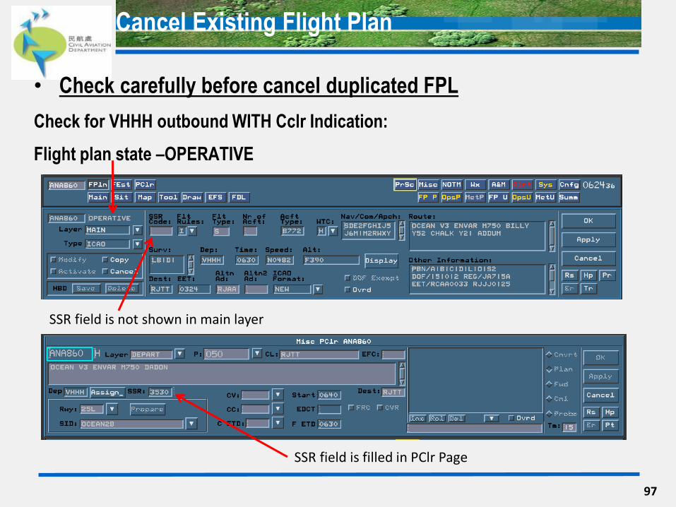
• Check carefully before cancel duplicated FPL
Check for VHHH outbound WITH Cclr Indication:
Flight plan state –OPERATIVE
97
SSR field is filled in PClr Page
SSR field is not shown in main layer
Cancel Existing Flight Plan
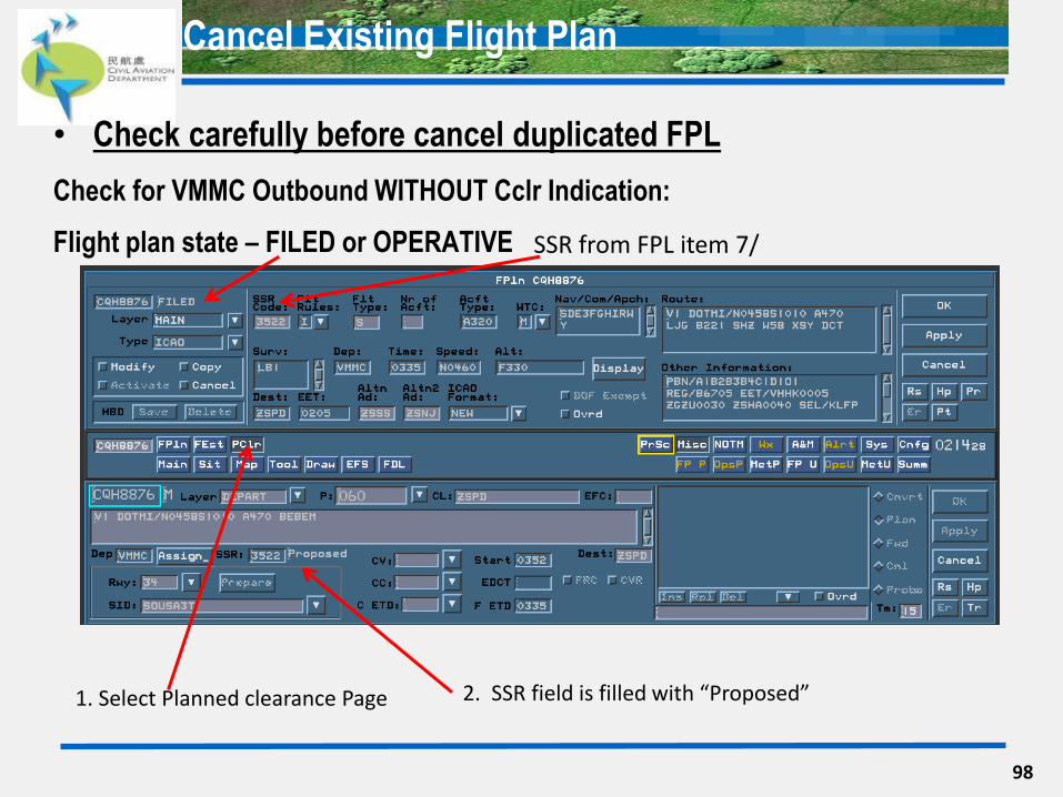
• Check carefully before cancel duplicated FPL
Check for VMMC Outbound WITHOUT Cclr Indication:
Flight plan state – FILED or OPERATIVE
98
1. Select Planned clearance Page 2. SSR field is filled with “Proposed”
SSR from FPL item 7/
Cancel Existing Flight Plan
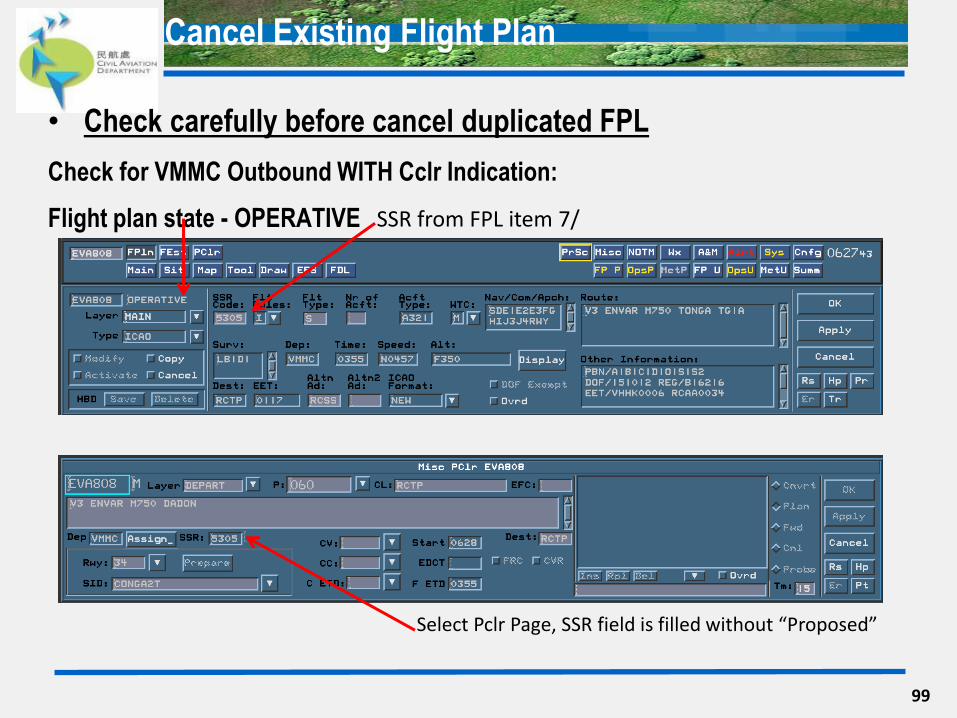
• Check carefully before cancel duplicated FPL
Check for VMMC Outbound WITH Cclr Indication:
Flight plan state - OPERATIVE
99
Select Pclr Page, SSR field is filled without “Proposed”
SSR from FPL item 7/
Cancel Existing Flight Plan
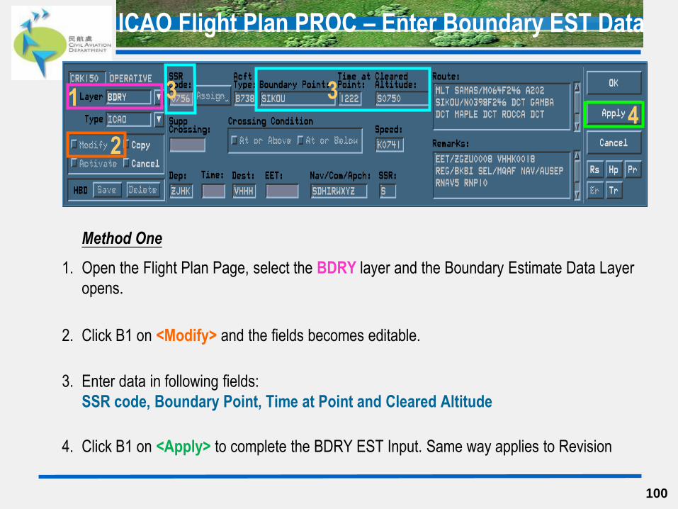
Method One
1. Open the Flight Plan Page, select the BDRY layer and the Boundary Estimate Data Layer
opens.
2. Click B1 on <Modify> and the fields becomes editable.
3. Enter data in following fields:
SSR code, Boundary Point, Time at Point and Cleared Altitude
4. Click B1 on <Apply> to complete the BDRY EST Input. Same way applies to Revision
100
3 1
2
4
ICAO Flight Plan PROC – Enter Boundary EST Data
101
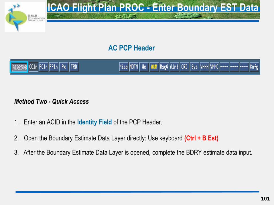
Method Two - Quick Access
1. Enter an ACID in the Identity Field of the PCP Header.
2. Open the Boundary Estimate Data Layer directly: Use keyboard (Ctrl + B Est)
3. After the Boundary Estimate Data Layer is opened, complete the BDRY estimate data input.
ICAO Flight Plan PROC - Enter Boundary EST Data
AC PCP Header
102
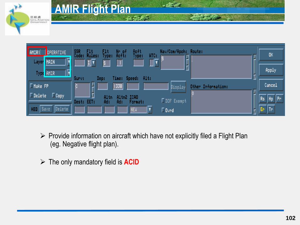
AMIR Flight Plan
Provide information on aircraft which have not explicitly filed a Flight Plan (eg. Negative flight plan).
The only mandatory field is ACID
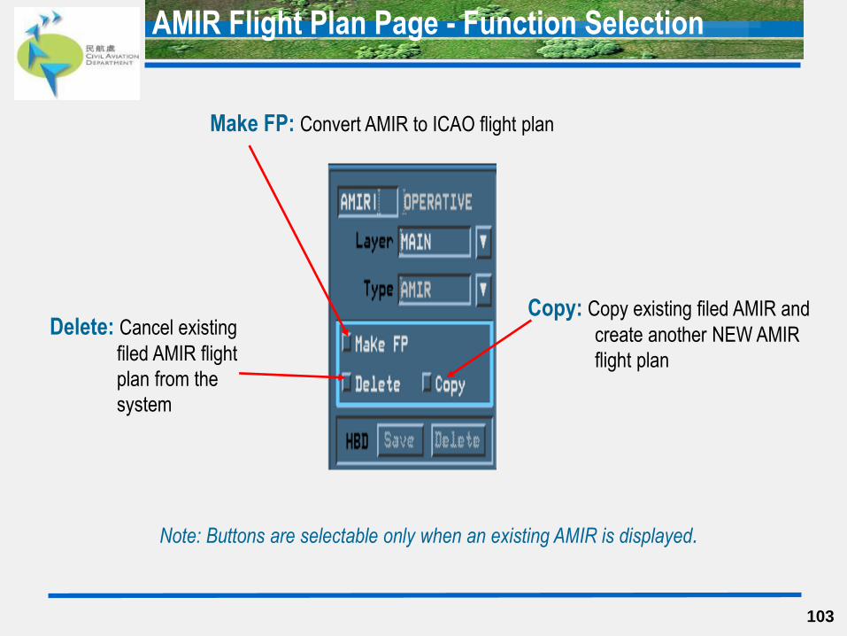
AMIR Flight Plan Page - Function Selection
103
Copy: Copy existing filed AMIR and
create another NEW AMIR
flight plan
Delete: Cancel existing
filed AMIR flight
plan from the
system
Make FP: Convert AMIR to ICAO flight plan
Note: Buttons are selectable only when an existing AMIR is displayed.
104
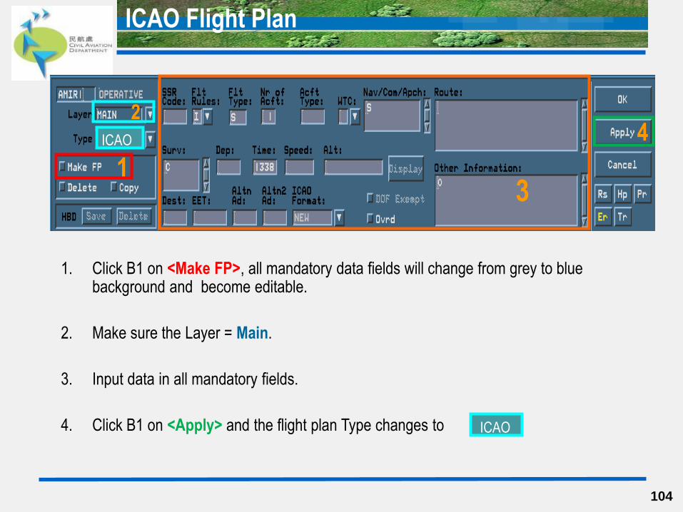
ICAO Flight Plan
1. Click B1 on <Make FP>, all mandatory data fields will change from grey to blue background and become editable.
2. Make sure the Layer = Main.
3. Input data in all mandatory fields.
4. Click B1 on <Apply> and the flight plan Type changes to
4
1
2
3
ICAO
ICAO
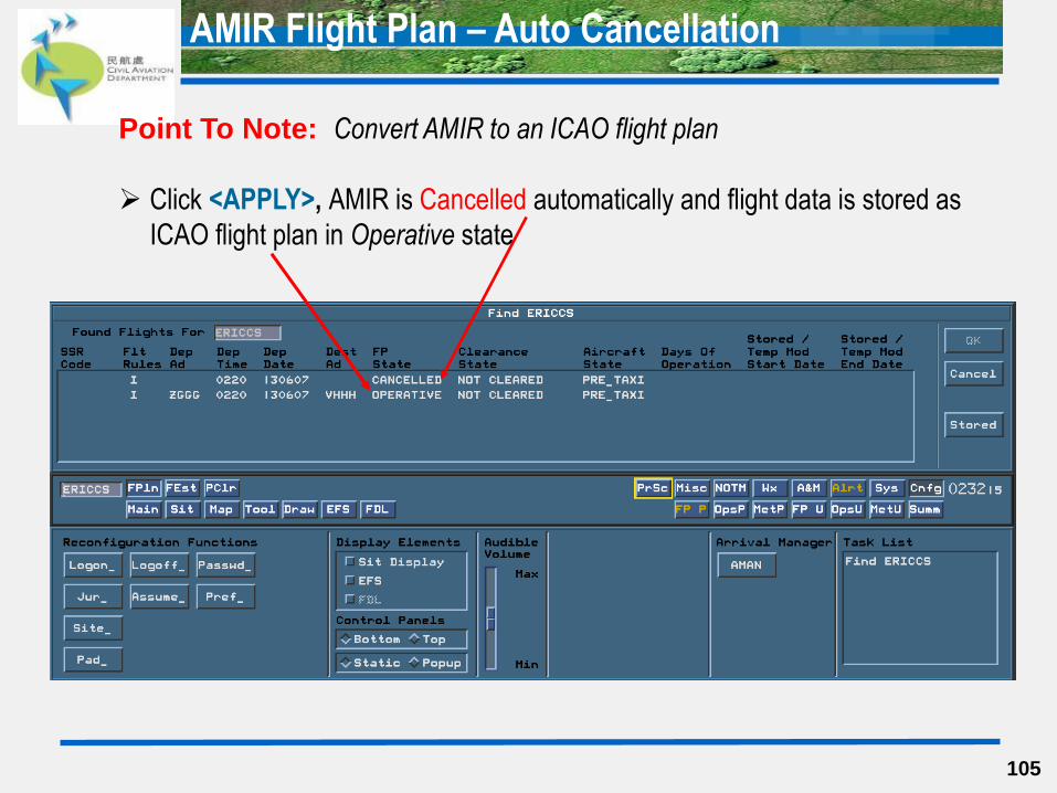
AMIR Flight Plan – Auto Cancellation
105
Point To Note: Convert AMIR to an ICAO flight plan
Click <APPLY>, AMIR is Cancelled automatically and flight data is stored as
ICAO flight plan in Operative state

106
Miscellaneous Functions Page
107
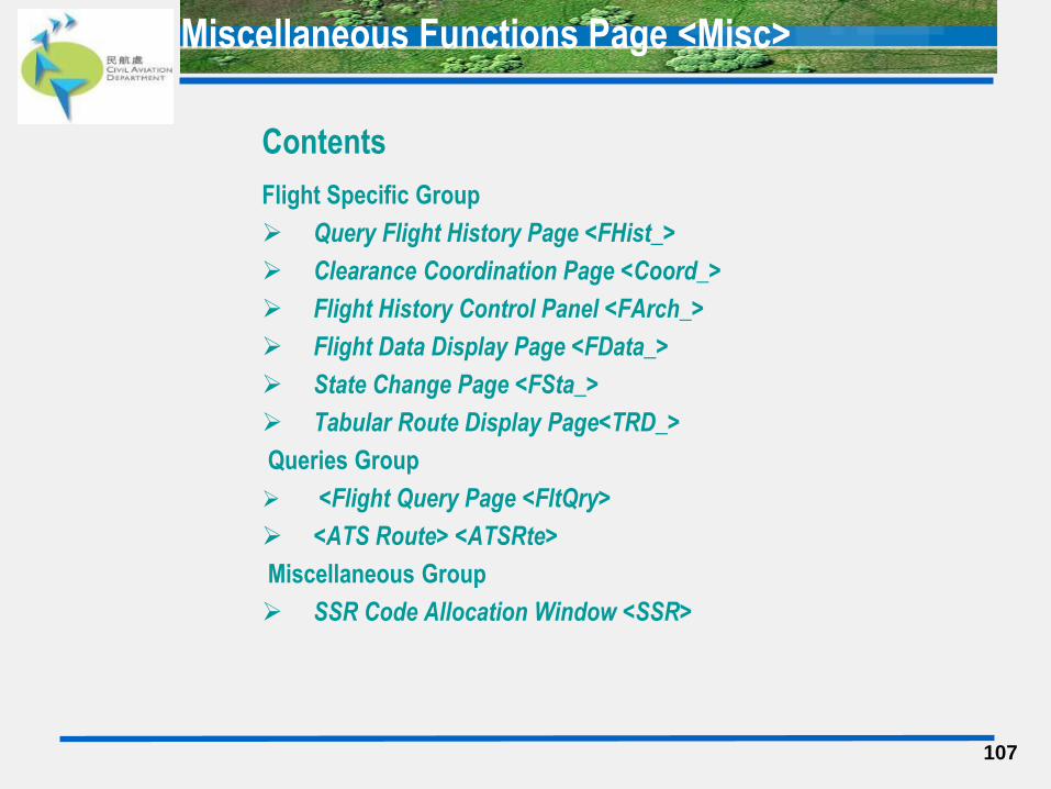
Contents
Flight Specific Group
Query Flight History Page <FHist_>
Clearance Coordination Page <Coord_>
Flight History Control Panel <FArch_>
Flight Data Display Page <FData_>
State Change Page <FSta_>
Tabular Route Display Page<TRD_>
Queries Group
<Flight Query Page <FltQry>
<ATS Route> <ATSRte>
Miscellaneous Group
SSR Code Allocation Window <SSR>
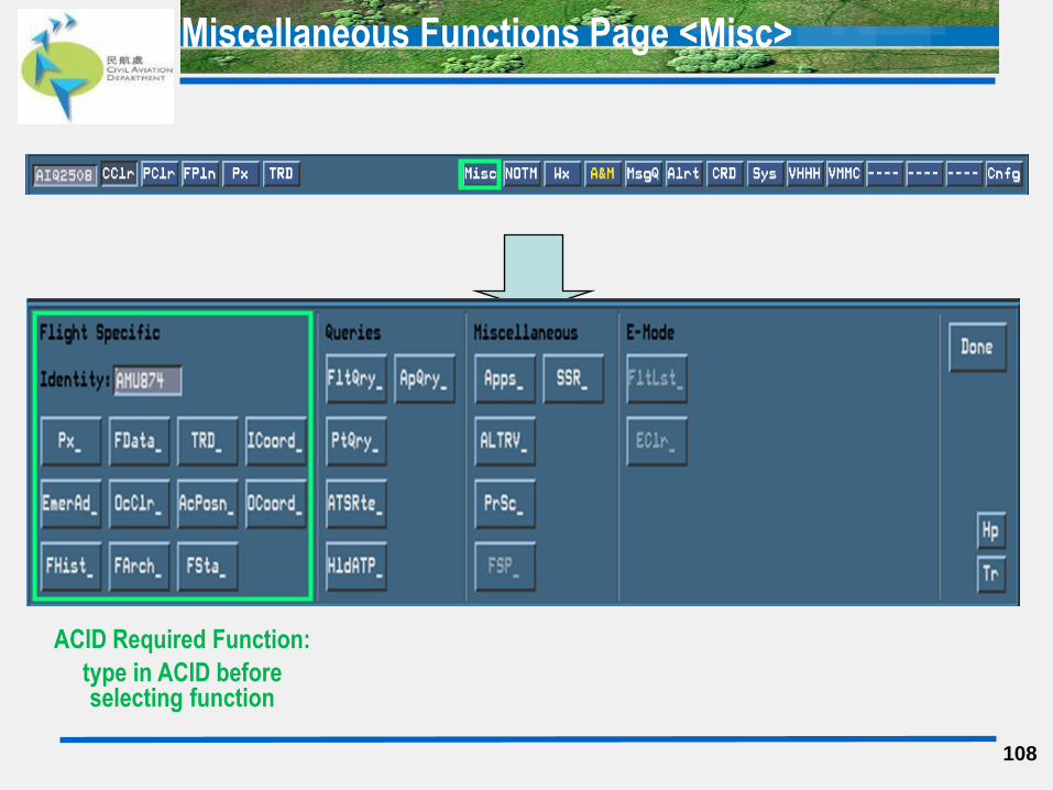
Miscellaneous Functions Page <Misc>
Miscellaneous Functions Page <Misc>
108
ACID Required Function:
type in ACID before selecting function
Query Flight History Page – FHist
109
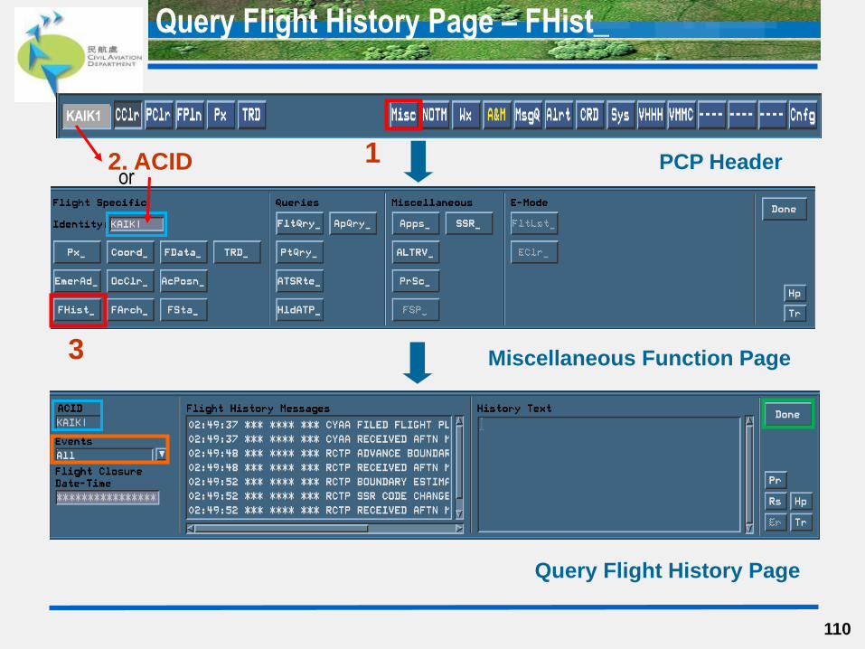
Steps
1. Click B1 on <Misc> of PCP Header to open the Query Flight Page.
2. Enter an ACID in the ACID Field.
3. Click B1 on <FHist> to open the Query Flight History Page.
4. The ACID is automatically filled up the ACID Field of the Miscellaneous Function Page.
5. Select the required Events type of the flight for viewing the flight history.
6. Related history message entries will be displayed under the Flight History Message field.
7. Select the required flight history message entry, the text will be displayed under History
Text field.
8. Click <Done> to close the Query Flight History Page.
Query Flight History Page – FHist_
110
2. ACID PCP Header
Query Flight History Page
3
1
Miscellaneous Function Page
KAIK1
or
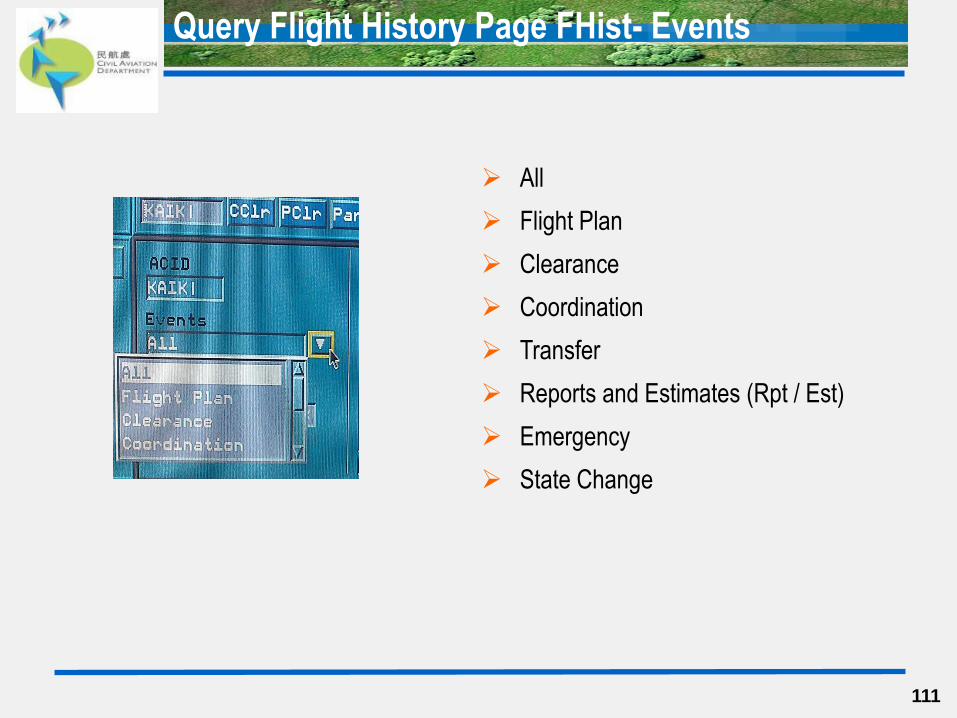
Query Flight History Page FHist- Events
111
All
Flight Plan
Clearance
Coordination
Transfer
Reports and Estimates (Rpt / Est)
Emergency
State Change
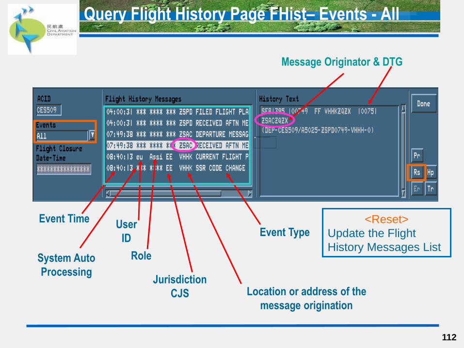
Query Flight History Page FHist– Events - All
112
Event Type
Event Time User
ID
Jurisdiction
CJS
Role
Location or address of the
message origination
<Reset>
Update the Flight
History Messages List
Message Originator & DTG
System Auto
Processing
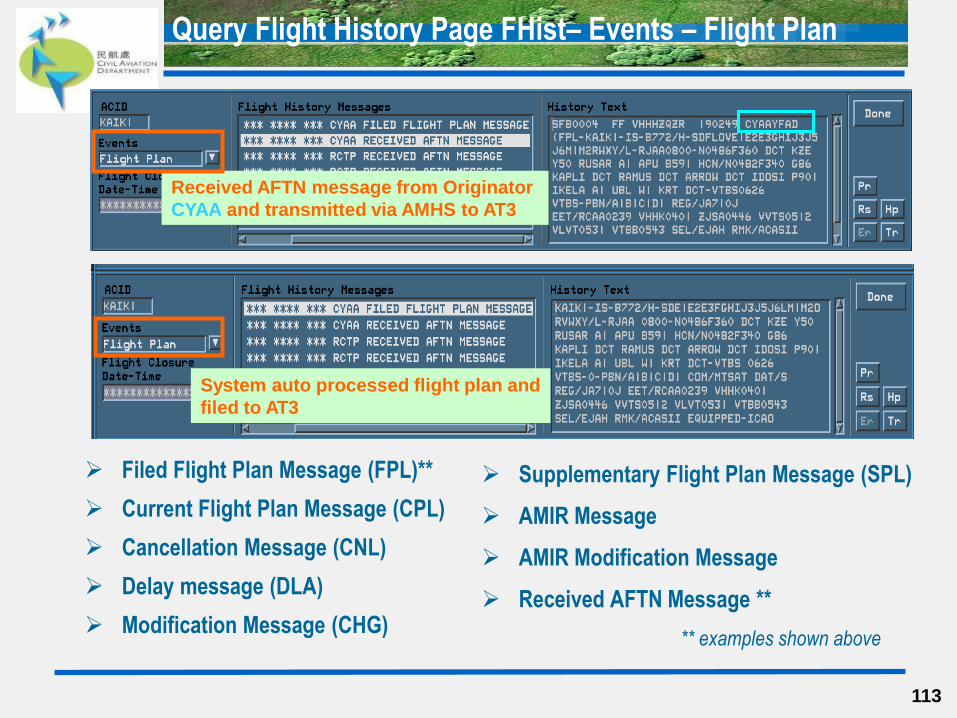
Query Flight History Page FHist– Events – Flight Plan
Filed Flight Plan Message (FPL)**
Current Flight Plan Message (CPL)
Cancellation Message (CNL)
Delay message (DLA)
Modification Message (CHG)
113
Supplementary Flight Plan Message (SPL)
AMIR Message
AMIR Modification Message
Received AFTN Message **
** examples shown above
Received AFTN message from Originator
CYAA and transmitted via AMHS to AT3
System auto processed flight plan and
filed to AT3
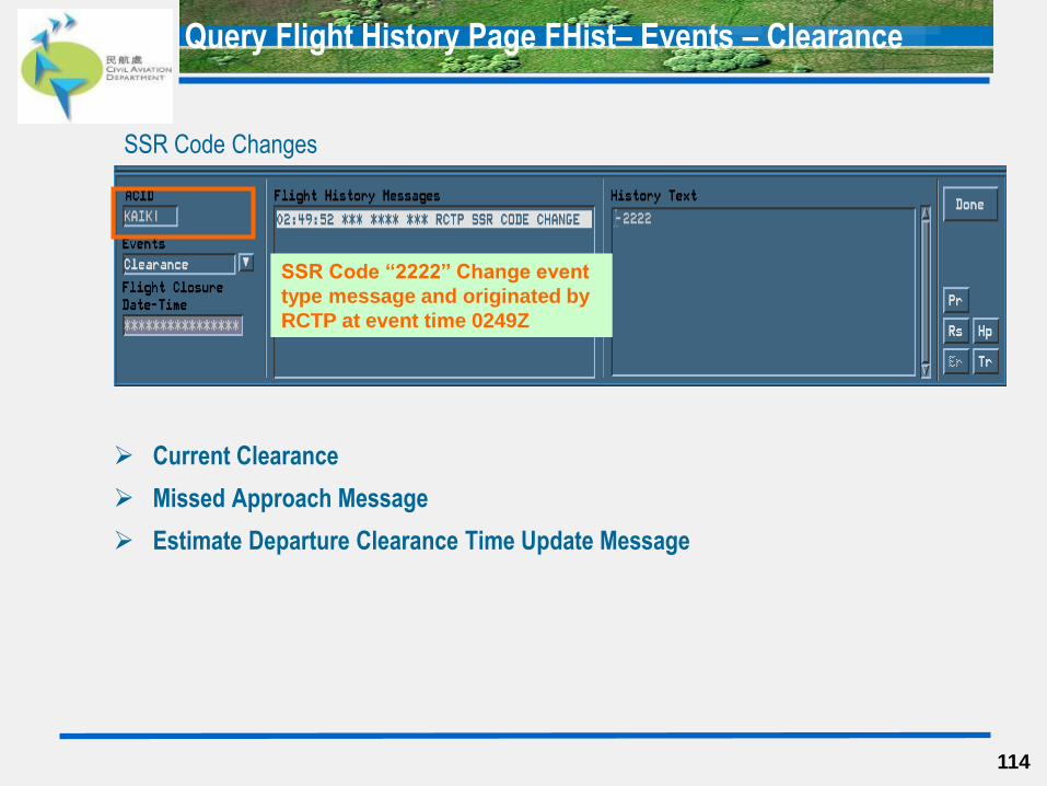
Current Clearance
Missed Approach Message
Estimate Departure Clearance Time Update Message
114
Query Flight History Page FHist– Events – Clearance
SSR Code “2222” Change event
type message and originated by
RCTP at event time 0249Z
SSR Code Changes

Coordination Message (CDN)
Coordination Rejection Message (REJ)
115
Query Flight History Page FHist– Events – Coordination
Advance Boundary Information Message (ABI)
Coordination Acceptance Message (ACP)

Query Flight History Page FHist– Events – Transfer
116
Handoff Initiate **
Handoff Accept
Handoff Reject
Handoff Recall
** example shown above
Auto Handoff Initiate
Auto Handoff Accept
Block Handoff
Jurisdiction Mismatch
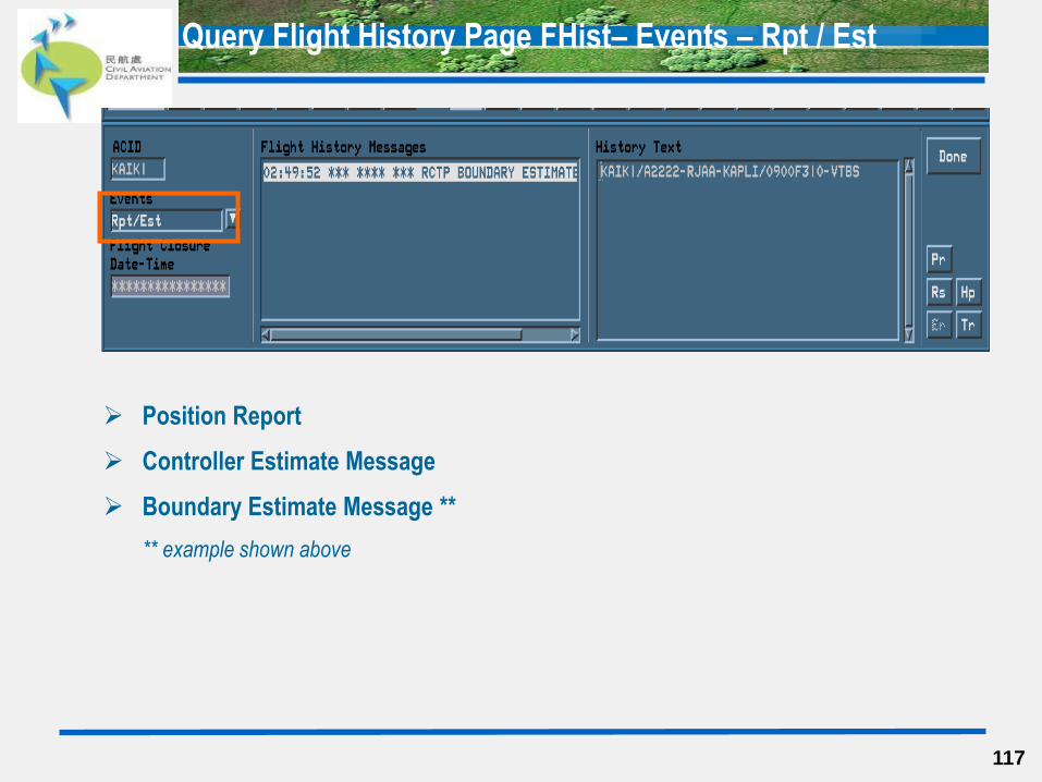
Query Flight History Page FHist– Events – Rpt / Est
Position Report
Controller Estimate Message
Boundary Estimate Message **
** example shown above
117
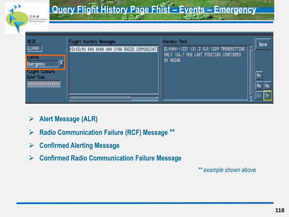
Query Flight History Page Fhist – Events – Emergency
118
Alert Message (ALR)
Radio Communication Failure (RCF) Message **
Confirmed Alerting Message
Confirmed Radio Communication Failure Message
** example shown above
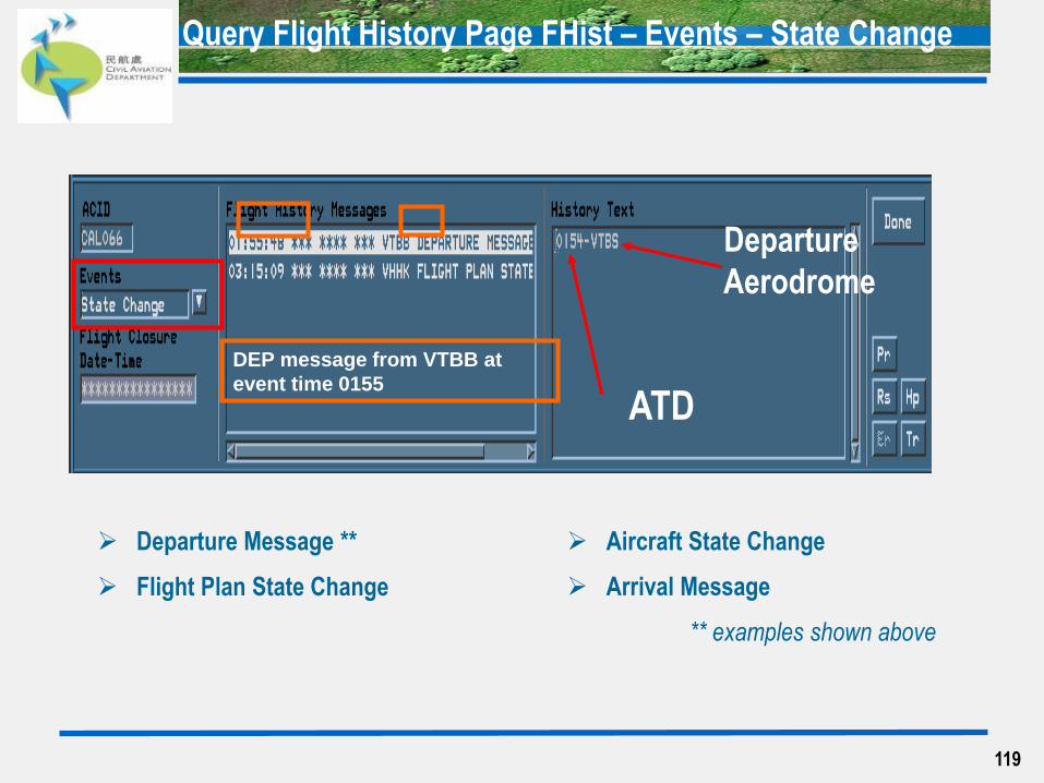
Departure Message **
Flight Plan State Change
Query Flight History Page FHist – Events – State Change
DEP message from VTBB at
event time 0155
Aircraft State Change
Arrival Message
** examples shown above
Departure
Aerodrome
ATD
119
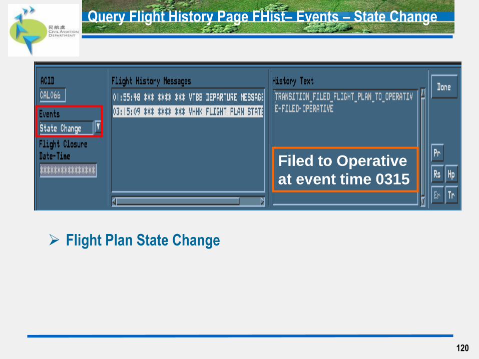
Flight Plan State Change
Query Flight History Page FHist– Events – State Change
Filed to Operative
at event time 0315
120
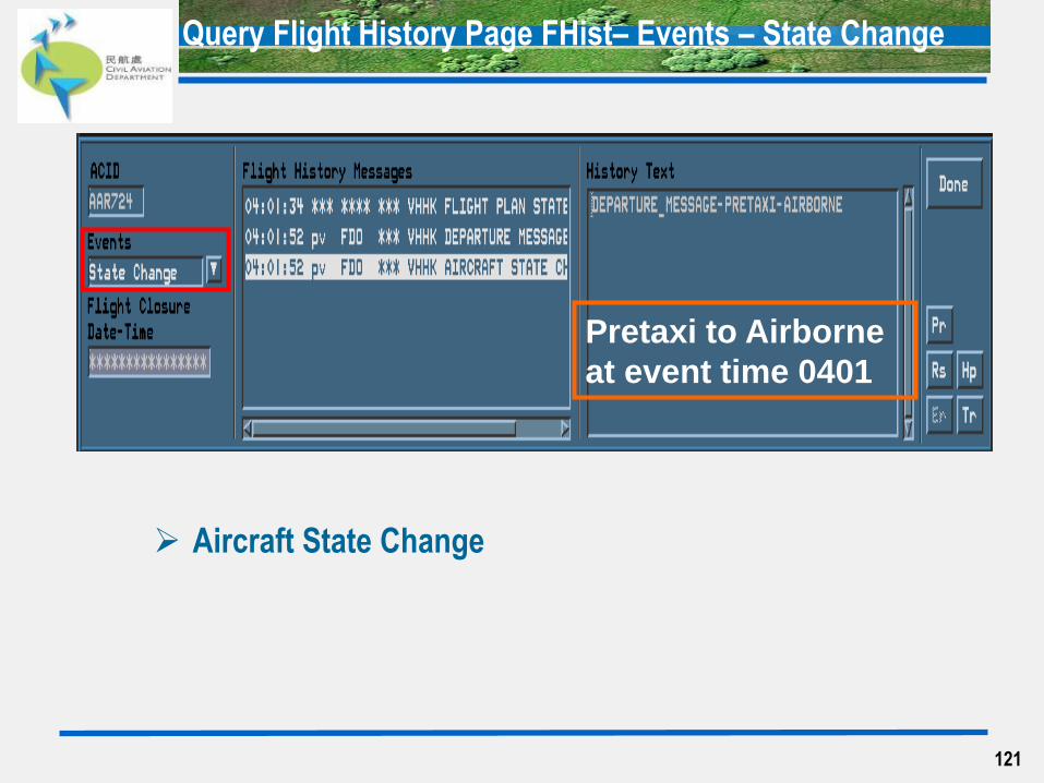
Query Flight History Page FHist– Events – State Change
Aircraft State Change
Pretaxi to Airborne
at event time 0401
121
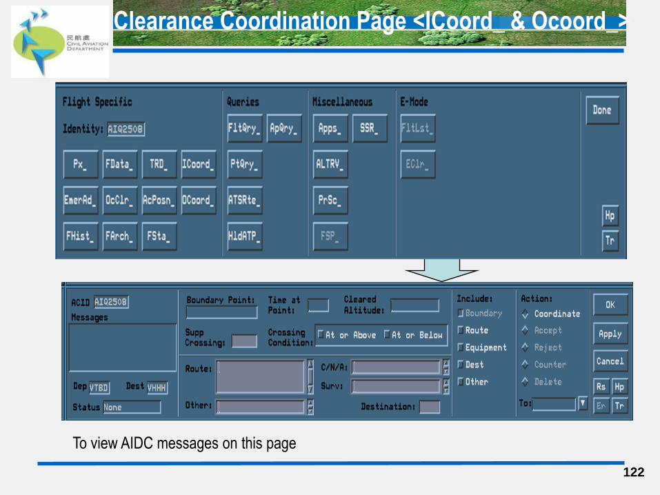
Clearance Coordination Page <ICoord_ & Ocoord_>
122
To view AIDC messages on this page

Find Flight Window <FArch_>
123
Invoke this page to retrieve flight archive (Closed and Cancelled FPL)
It will show the entry according to date
The system will store maximum 31 days of flight archive
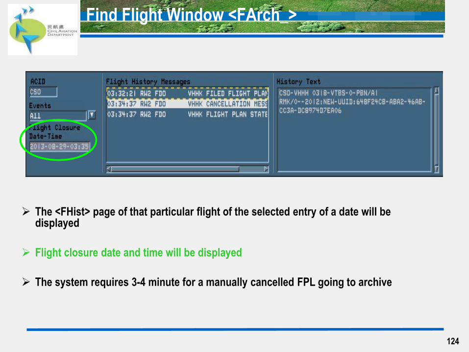
Find Flight Window <FArch_>
The <FHist> page of that particular flight of the selected entry of a date will be displayed
Flight closure date and time will be displayed
The system requires 3-4 minute for a manually cancelled FPL going to archive
124
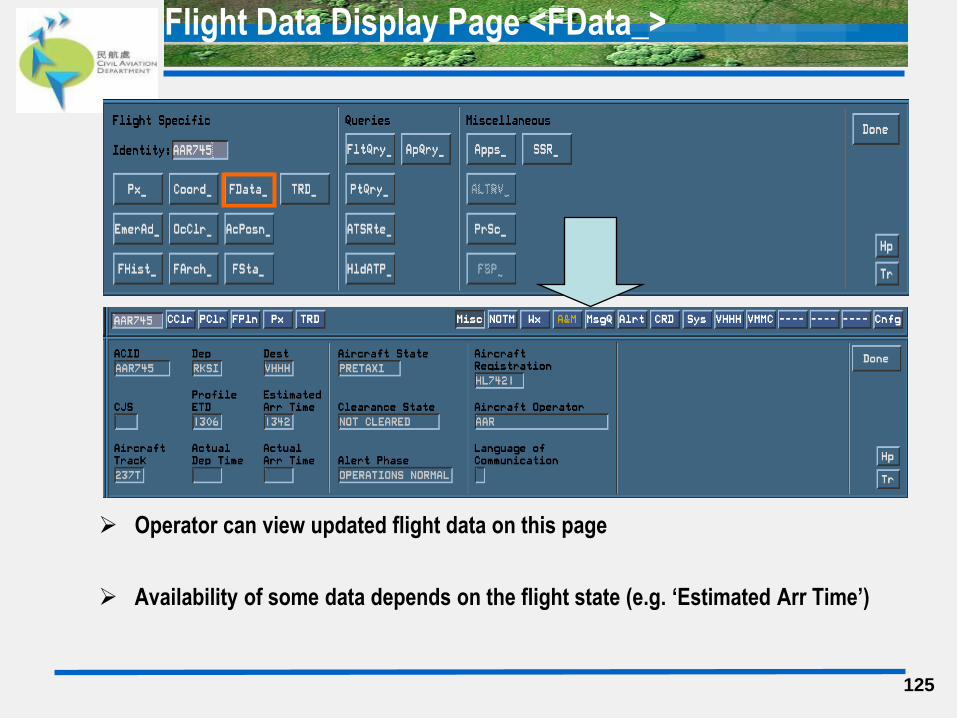
Flight Data Display Page <FData_>
Operator can view updated flight data on this page
Availability of some data depends on the flight state (e.g. ‘Estimated Arr Time’)
125

Flight Data Display Page <FData_>
Function Description & Options
Profile ETD • EOBT
Estimated Arr Time • For O/B & OVF flights = ETO of one point beyond VHHK
(outgoing VHHK)
• For I/B flights = ETA
126
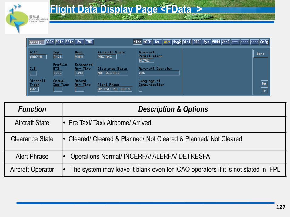
Flight Data Display Page <FData_>
Function Description & Options
Aircraft State • Pre Taxi/ Taxi/ Airborne/ Arrived
Clearance State • Cleared/ Cleared & Planned/ Not Cleared & Planned/ Not Cleared
Alert Phrase • Operations Normal/ INCERFA/ ALERFA/ DETRESFA
Aircraft Operator • The system may leave it blank even for ICAO operators if it is not stated in FPL
127
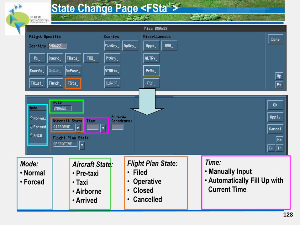
State Change Page <FSta_>
128
Aircraft State:
• Pre-taxi
• Taxi
• Airborne
• Arrived
Flight Plan State:
• Filed
• Operative
• Closed
• Cancelled
Mode:
• Normal
• Forced
Time:
• Manually Input
• Automatically Fill Up with
Current Time
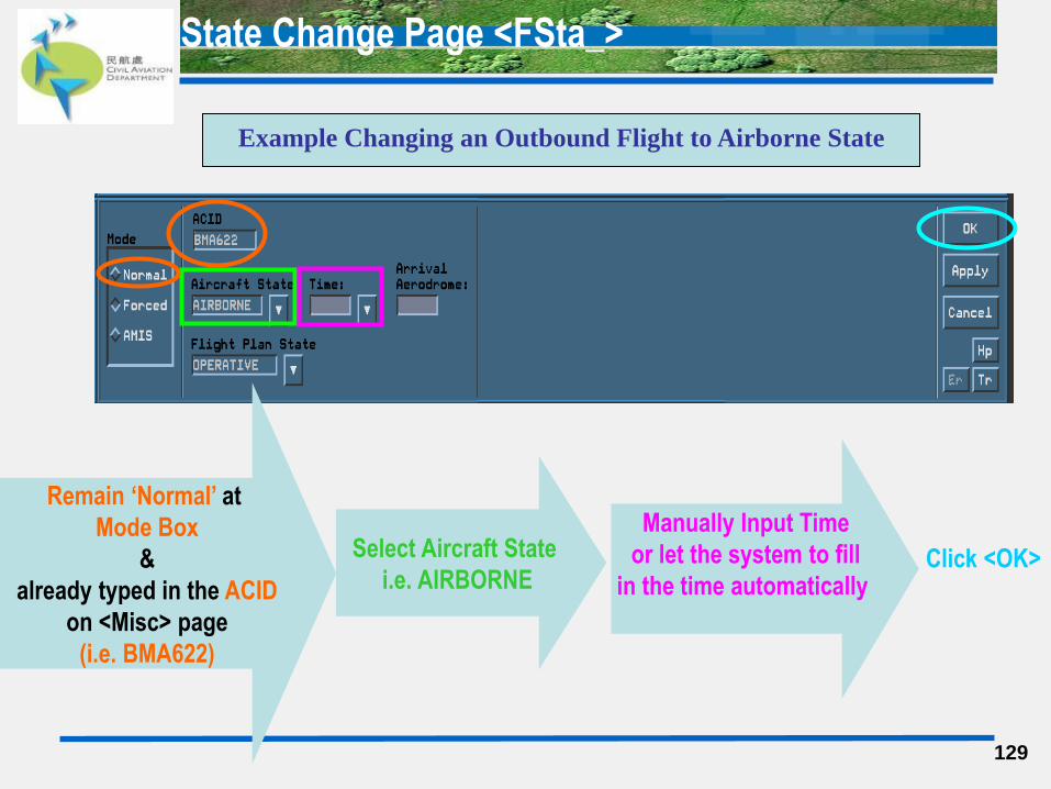
State Change Page <FSta_>
129
Remain ‘Normal’ at
Mode Box
&
already typed in the ACID
on <Misc> page
(i.e. BMA622)
Select Aircraft State
i.e. AIRBORNE
Manually Input Time
or let the system to fill
in the time automatically
Click <OK>
Example Changing an Outbound Flight to Airborne State
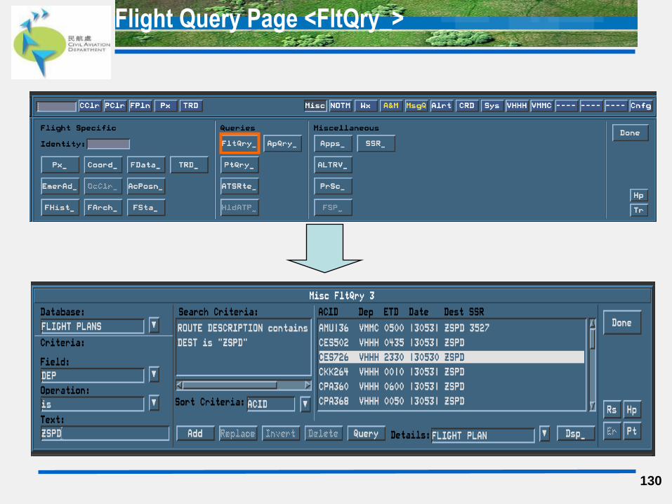
Flight Query Page <FltQry_>
130

Flight Query Page <FltQry_>
131
Field:
Total 41 choices.
e.g. ACID, DEP,
Route points or even
pilot name etc
Operation:
Total 9 choices
‘=‘ / ‘is’ / ‘contains’ etc
Available varies with
Field selected
Criteria Entered
For Free
Text Input
Database:
Flight Plans (defaulted)
Clearance
Flight Data
Stored Flights
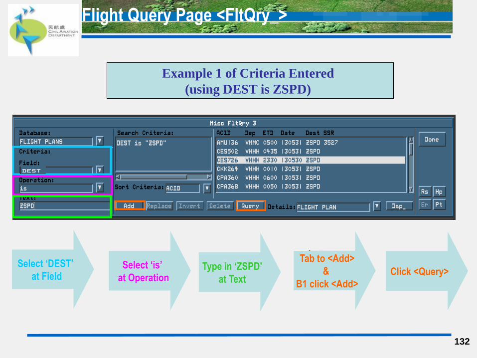
Flight Query Page <FltQry_>
132
Select ‘DEST’
at Field Select ‘is’
at Operation Type in ‘ZSPD’
at Text
Tab to <Add>
&
B1 click <Add> Click <Query>
Example 1 of Criteria Entered
(using DEST is ZSPD)
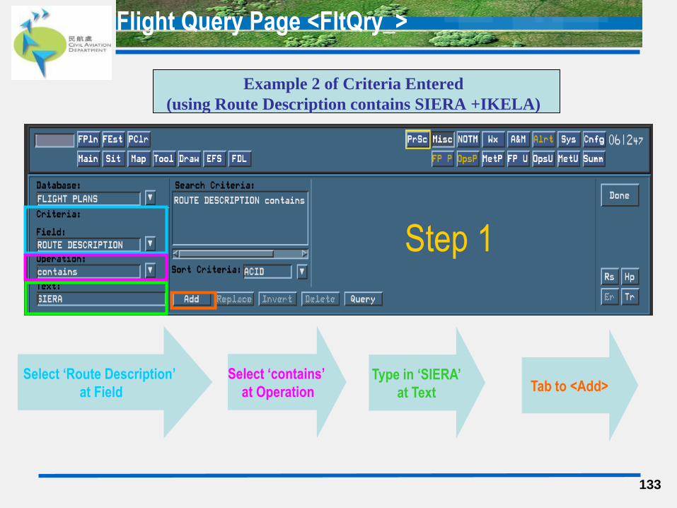
Flight Query Page <FltQry_>
Example 2 of Criteria Entered
(using Route Description contains SIERA +IKELA)
133
Select ‘Route Description’
at Field
Select ‘contains’
at Operation Type in ‘SIERA’
at Text Tab to <Add>
Step 1
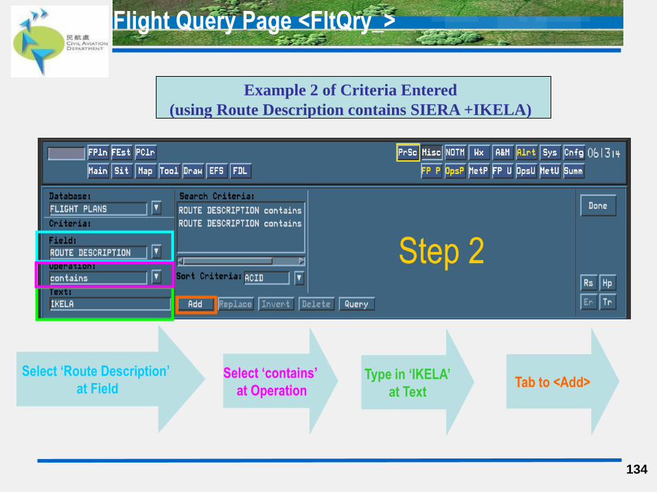
Flight Query Page <FltQry_>
134
Step 2
Select ‘Route Description’
at Field Select ‘contains’
at Operation Type in ‘IKELA’
at Text Tab to <Add>
Example 2 of Criteria Entered
(using Route Description contains SIERA +IKELA)
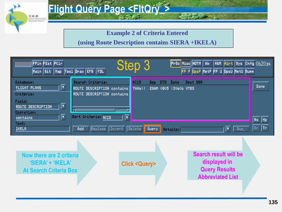
Flight Query Page <FltQry_>
Example 2 of Criteria Entered
(using Route Description contains SIERA +IKELA)
135
Now there are 2 criteria
‘SIERA’ + ‘IKELA’
At Search Criteria Box Click <Query>
Search result will be
displayed in
Query Results
Abbreviated List
Step 3
Flight Query Page <FltQry_>
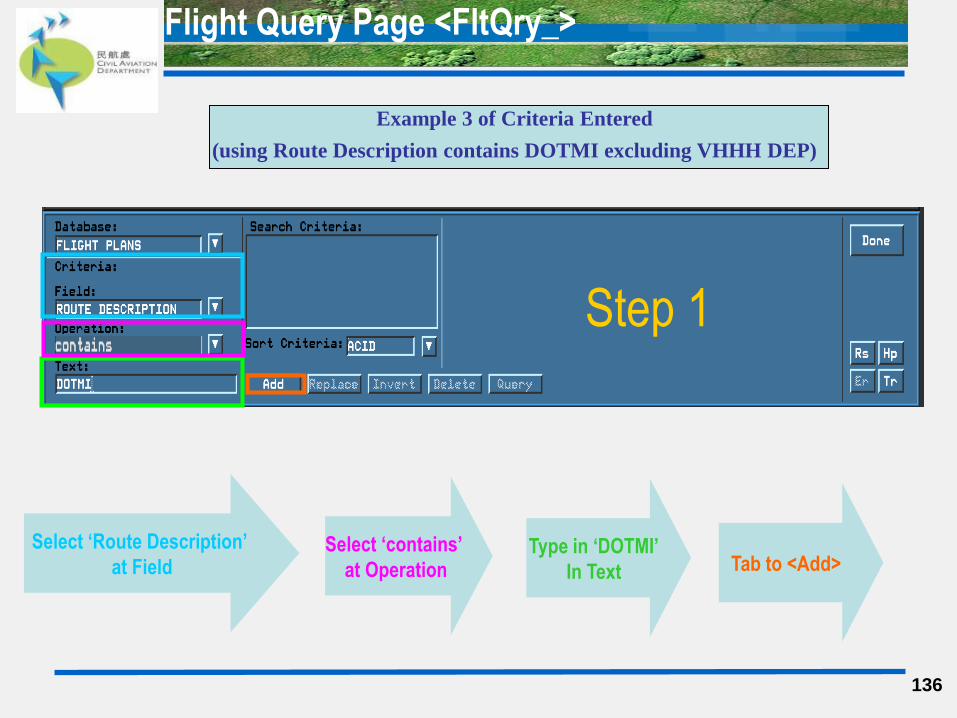
136
Example 3 of Criteria Entered
(using Route Description contains DOTMI excluding VHHH DEP)
Select ‘Route Description’
at Field Select ‘contains’
at Operation Type in ‘DOTMI’
In Text Tab to <Add>
Step 1
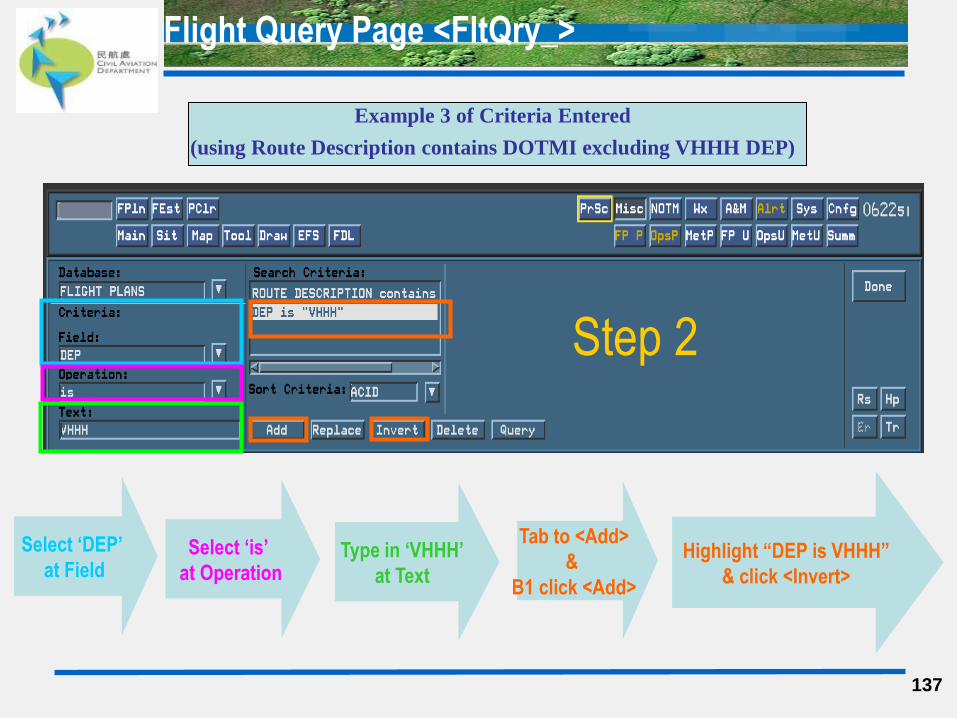
Flight Query Page <FltQry_>
137
Example 3 of Criteria Entered
(using Route Description contains DOTMI excluding VHHH DEP)
Select ‘DEP’
at Field Select ‘is’
at Operation Type in ‘VHHH’
at Text
Tab to <Add>
&
B1 click <Add>
Step 2
Highlight “DEP is VHHH”
& click <Invert>
Flight Query Page <FltQry_>
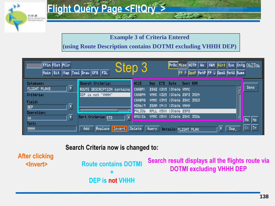
138
Search Criteria now is changed to:
Route contains DOTMI
+
DEP is not VHHH
Example 3 of Criteria Entered
(using Route Description contains DOTMI excluding VHHH DEP)
After clicking
<Invert> Search result displays all the flights route via
DOTMI excluding VHHH DEP
Step 3
Flight Query Page <FltQry_>
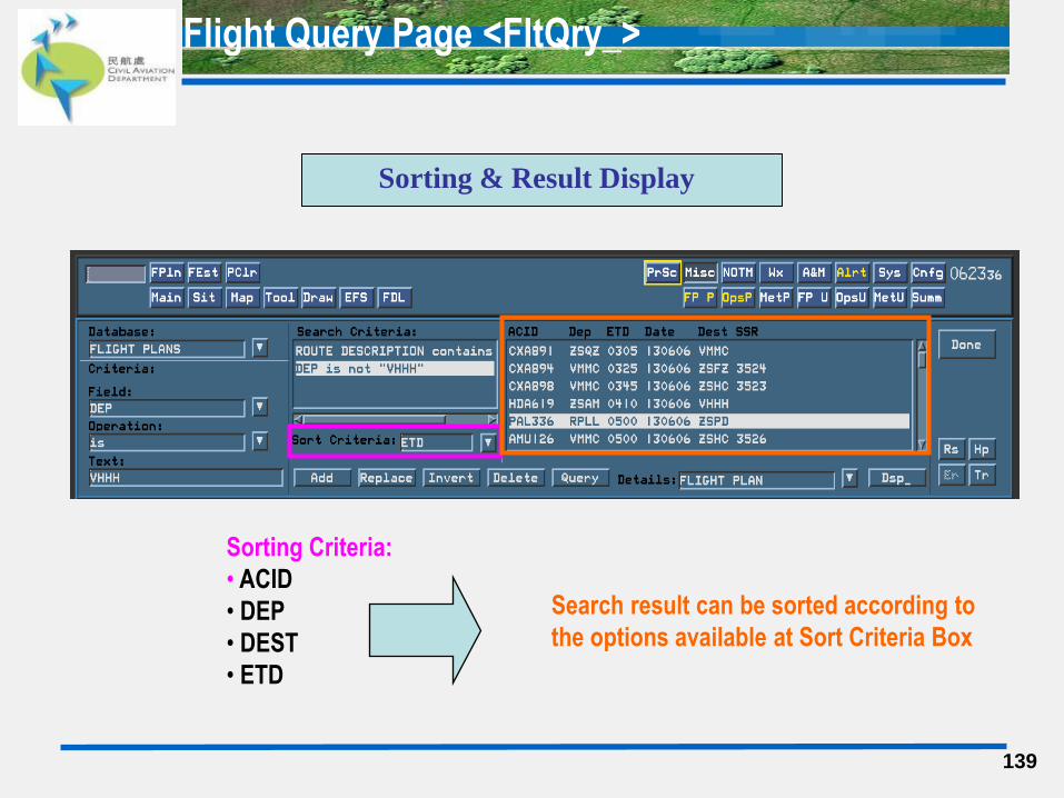
139
Sorting Criteria:
• ACID
• DEP
• DEST
• ETD
Sorting & Result Display
Search result can be sorted according to
the options available at Sort Criteria Box
Flight Query Page <FltQry_>
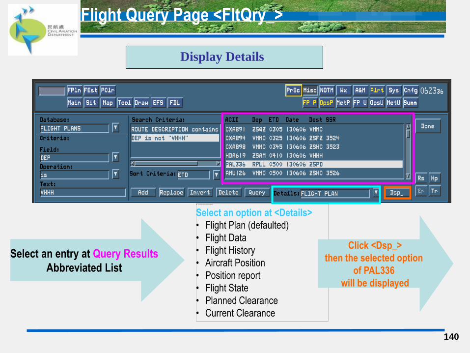
140
Display Details
Select an entry at Query Results
Abbreviated List
Select an option at <Details>
• Flight Plan (defaulted)
• Flight Data
• Flight History
• Aircraft Position
• Position report
• Flight State
• Planned Clearance
• Current Clearance
Click <Dsp_>
then the selected option
of PAL336
will be displayed

Flight Query Page <FltQry_>
141
There are 41 options available at Field Box, however, they are subject to the criteria selected
at Database Box. The Filed selected affects the options available at Operation Box.
•ACID
• SSR CODE
• DEP
• DEST
• ALTERNATIVE AERODROME
• ETD
• ETA
• ACC AOR AT TIME(s)
• FLIGHT RULES
• FLIGHT TYPE
• NUMBER OF AIRCRAFT
• AIRCRAFT TYPE
• AIRSPEED
• FLIGHT LEVEL
• ROUTE DESCRIPTION
• OTHER FPL INFO
• FUEL ENDURANCE
• PILOT NAME
• OPERAORS NOTE
• FIR ETO
• FLIGHT PLAN STATE
•CLEAR ISSUE TIME
• CLEAR LIMIT AERODROME
• CLEAR LIMIT FIX
• CLEARED ALTITUDE
• CC TIME (Clearance Cancel)
• CV TIME (Clearance Valid)
• OPERATIONAL TIME
• SPECIAL USE AIRSPACE
• CONTROL AREA
• TERM CONTROL AREA
• MIL TER CONTROL AREA
• CONTROL ZONE
• FLIGHT INFO REGION
• FIX
• TIME AT FIX
• AREA
• EFFECTIVE DATE
• VAILD UNTIL DATE
• DAYS OF OPERATION
• WAKE TURBULANCE
Flight Query Page <FltQry_>
(A) <Operation>
There are different options available at <Operation>
(which vary from the selection at Field Box:
• =
• <
• >
• is
• contains etc
(B) <Text>
Searching text criteria depends on the selection at <Field>. For example,
if ‘Flight Rules’ is selected at <Field> then operator can only type in ‘I’ , ‘V’, ‘ Y’ and ‘Z’.
142
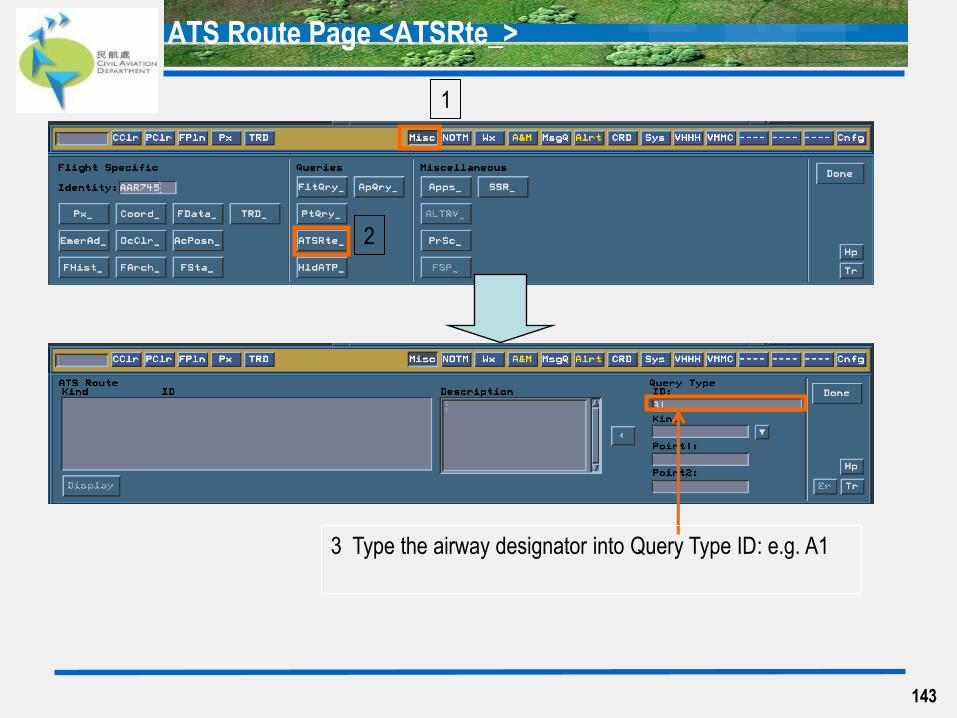
ATS Route Page <ATSRte_>
143
1
2
3 Type the airway designator into Query Type ID: e.g. A1
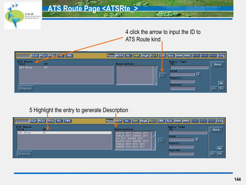
ATS Route Page <ATSRte_>
144
5 Highlight the entry to generate Description
4 click the arrow to input the ID to
ATS Route kind
SSR Code Allocation Window <SSR_>
145

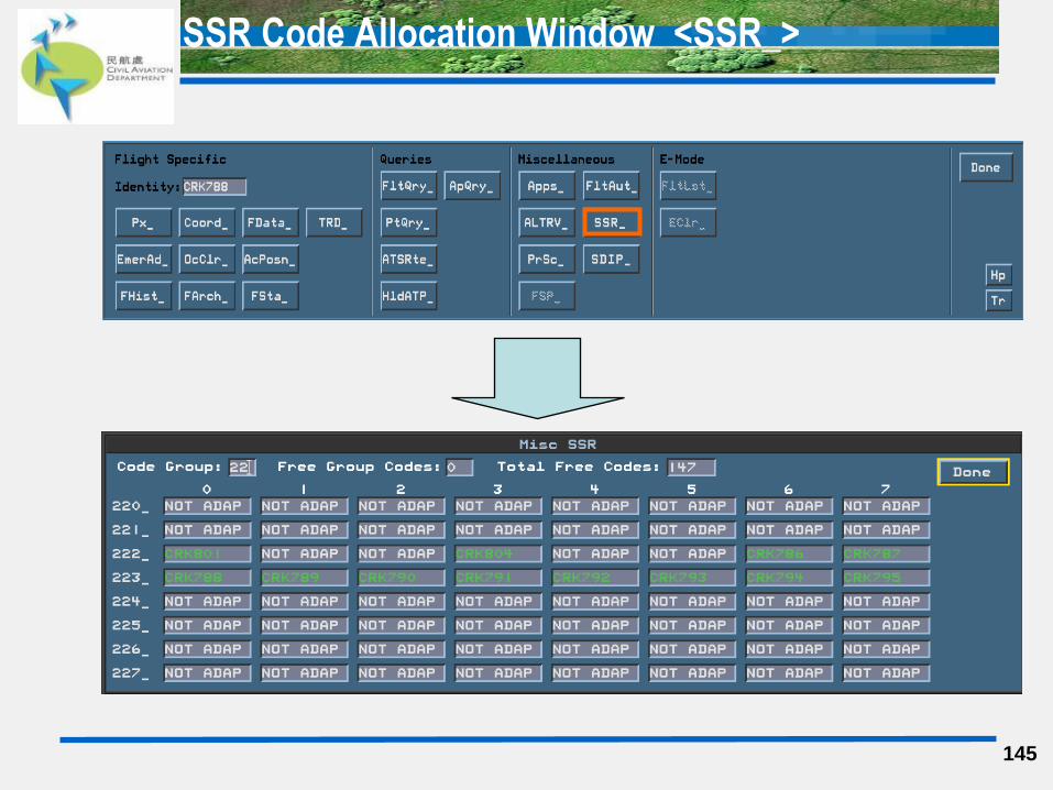
SSR Code Allocation Window <SSR_>
146
‘NOT ADAP’ means this SSR code is available for manual assignment
The SSR code with an ACID means it is occupied by that flight and not available
for manual assignment
‘Free Group Codes’ shows how many SSR code for that particular code group
(e.g. code starts from ’22’) is available for allocation
Empty Boxes means those codes are reserved in the system and not suitable for
manual assignment

EFS
147
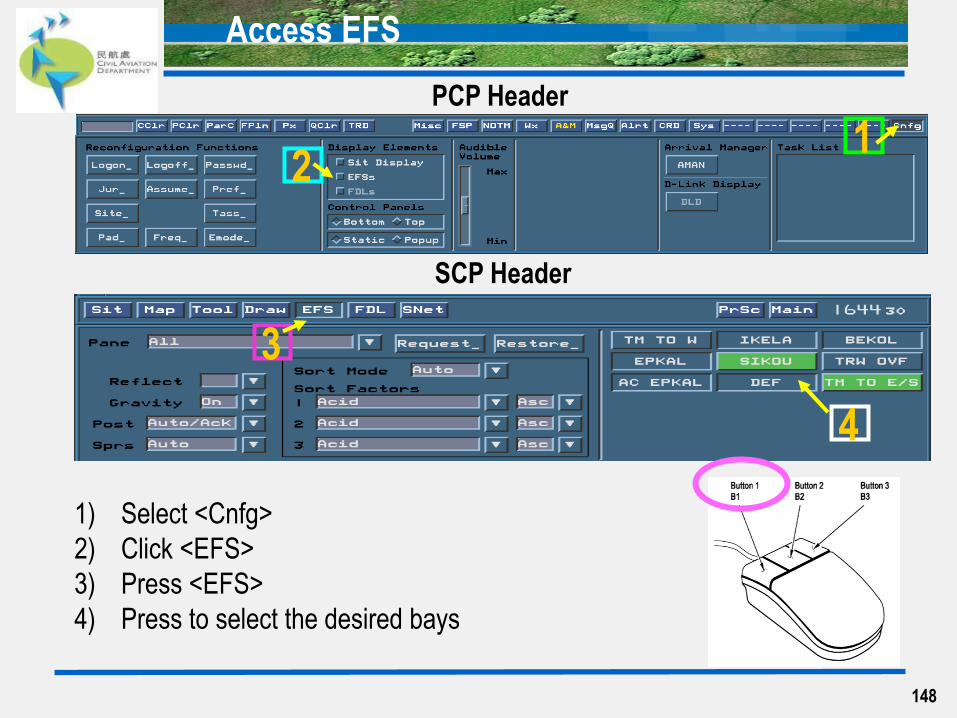
Access EFS
PCP Header
SCP Header
1 2
3
4
1) Select <Cnfg>
2) Click <EFS>
3) Press <EFS>
4) Press to select the desired bays
148
149
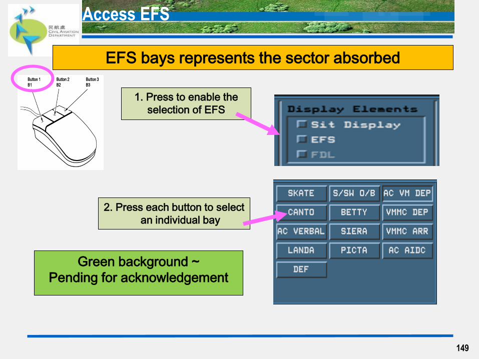
EFS bays represents the sector absorbed
Green background ~
Pending for acknowledgement
2. Press each button to select
an individual bay
1. Press to enable the
selection of EFS
Access EFS
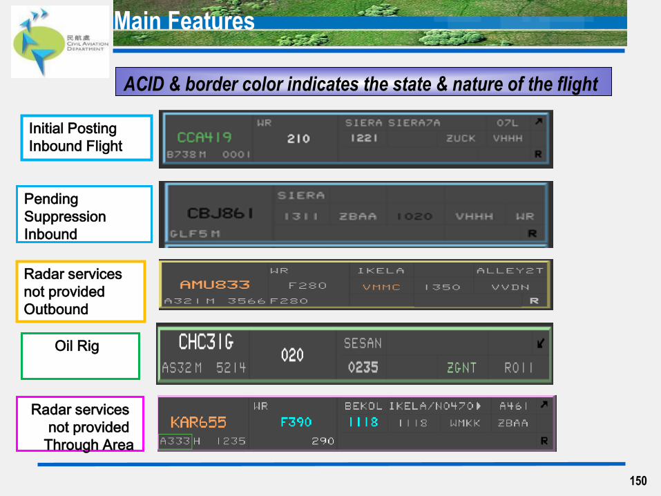
Main Features
Oil Rig
150
Initial Posting
Inbound Flight
Pending
Suppression
Inbound
Radar services
not provided
Outbound
Radar services
not provided
Through Area
ACID & border color indicates the state & nature of the flight

151
Window Title Bar Obscured EFS Counter
Electronic Flight Strip (EFS)
Window Menu
Includes ‘Move’,
‘Size’ and
‘Lower’ function
Displays no. of
EFSs that are
not visible
in the pane
Electronic Flight Strip <EFS> window
Cock EFS
152
EFS Tool Palette
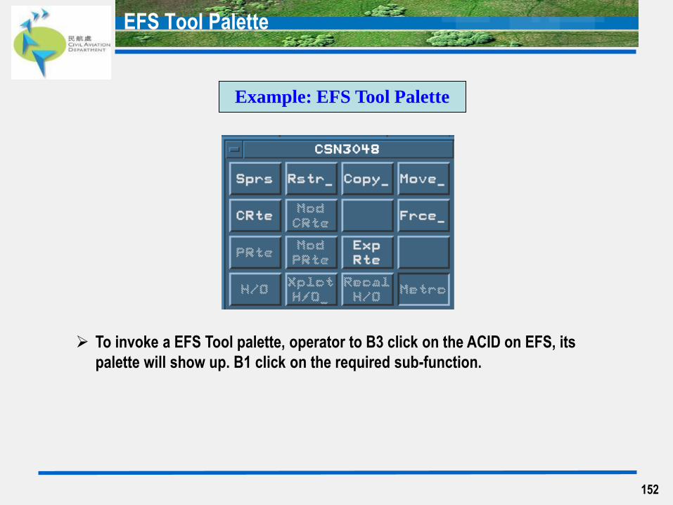
Example: EFS Tool Palette
To invoke a EFS Tool palette, operator to B3 click on the ACID on EFS, its
palette will show up. B1 click on the required sub-function.

153
Inbound & OVF In
posting/suppression rules of pending EFS
Area AC (EA/ WA/ SA)
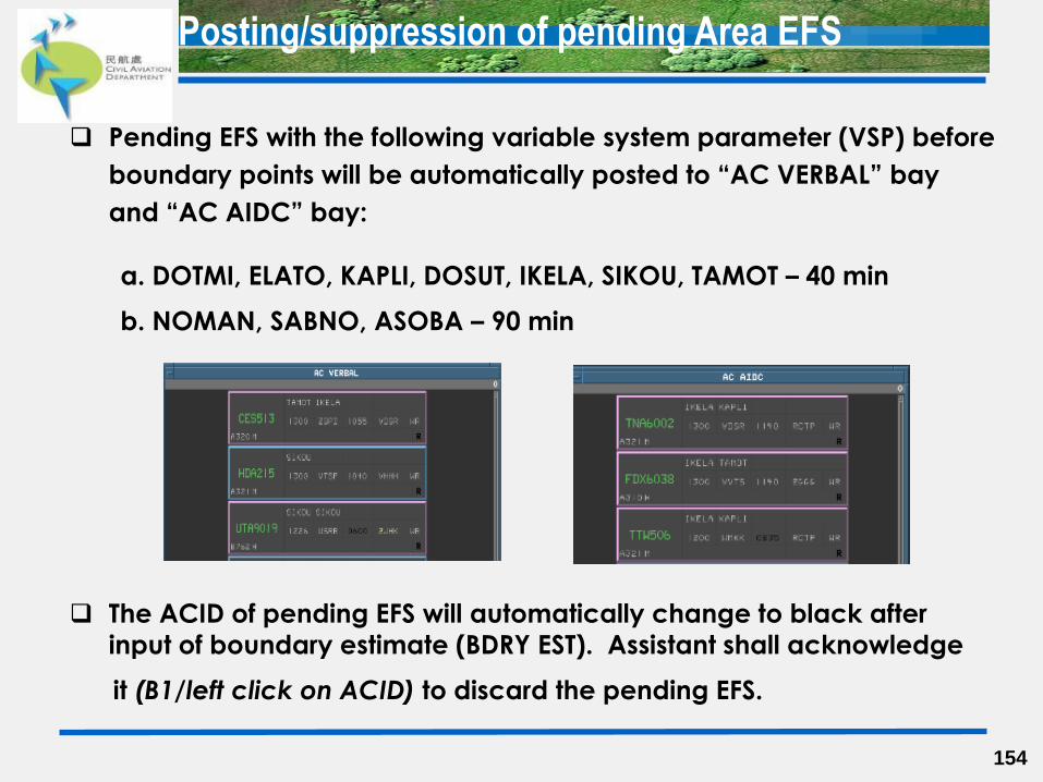
Pending EFS with the following variable system parameter (VSP) before
boundary points will be automatically posted to “AC VERBAL” bay
and “AC AIDC” bay:
a. DOTMI, ELATO, KAPLI, DOSUT, IKELA, SIKOU, TAMOT – 40 min
b. NOMAN, SABNO, ASOBA – 90 min
The ACID of pending EFS will automatically change to black after
input of boundary estimate (BDRY EST). Assistant shall acknowledge
it (B1/left click on ACID) to discard the pending EFS.
154
Posting/suppression of pending Area EFS
155
Inbound & OVF In
pending EFS posting/suppression and sorting rule
for “AC VERBAL” bay and “AC AIDC” bay
Area AC (EA/ WA/ SA)
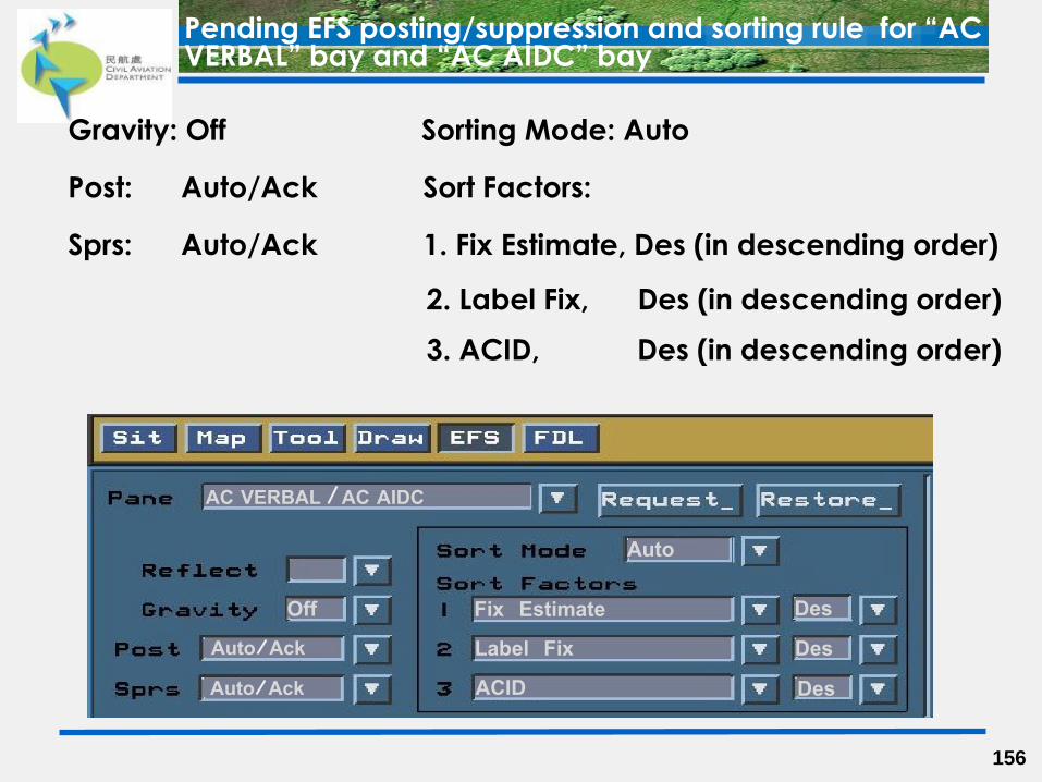
Gravity: Off Sorting Mode: Auto
Post: Auto/Ack Sort Factors:
Sprs: Auto/Ack 1. Fix Estimate, Des (in descending order)
2. Label Fix, Des (in descending order)
3. ACID, Des (in descending order)
156
Pending EFS posting/suppression and sorting rule for “AC VERBAL” bay and “AC AIDC” bay
AC VERBAL AC AIDC
Off Auto Ack Auto Ack
Auto
Fix Estimate Label Fix ACID
Des Des Des
Area AC (EA/ WA/ SA)
157
Inbound & OVF In
posting/suppression & format of active EFS
After input of boundary estimate (BDRY EST) of
inbound/overfly flight, active EFS will be posted to active
pane of appropriate “boundary fix” bay.
The ACID of active EFS will automatically change to black when the aircraft leaves the sector. Assistant shall
acknowledge it (B1/left click on ACID of active EFS)
to discard the active EFS.
Each assistant will have appropriate “Boundary Fix” bays
for boundary points which is subject to the jurisdictions
being logged on by his/her executive.
158
Posting/suppression of active EFS
Each boundary point is allocated with one bay and maximum of two
boundary points share one bay.
E.G. DOSUT and ASOBA share one bay.
Most “boundary fix” bays are
divided in two panes:
a. Pending pane:
- HK and Macao departures with
SID/SSR code
(refer to slide 61 for further details)
b. Active pane:
- HK & Macao departures already
airborne and traffic with BDRY EST.
Some “boundary fix” bays, e.g. TAMOT bay does not handle HK &
Macao departures, do not have two separate panes.
159
Posting/suppression of active EFS (con’t)
160
Inbound & OVF In
active EFS posting/suppression and sorting rule
for “boundary fix” bay – active pane
Active EFS posting/suppression and sorting rule for “boundary fix” bay - active pane
161
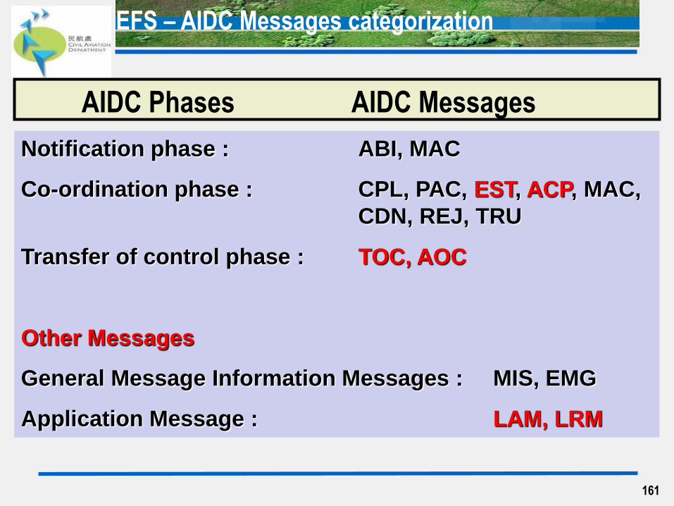
Notification phase : ABI, MAC
Co-ordination phase : CPL, PAC, EST, ACP, MAC,
CDN, REJ, TRU
Transfer of control phase : TOC, AOC
Other Messages
General Message Information Messages : MIS, EMG
Application Message : LAM, LRM
EFS – AIDC Messages categorization
AIDC Phases AIDC Messages
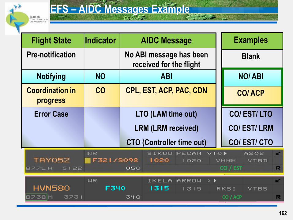
Flight State Indicator AIDC Message
Pre-notification No ABI message has been
received for the flight
Notifying NO ABI
Coordination in
progress
CO CPL, EST, ACP, PAC, CDN
Error Case LTO (LAM time out)
LRM (LRM received)
CTO (Controller time out)
162
EFS – AIDC Messages Example
Examples
Blank
NO/ ABI
CO/ ACP
CO/ EST/ LTO
CO/ EST/ LRM
CO/ EST/ CTO
Terminal AC (TA)
163
WMMC DEP
posting/suppression rules of pending EFS with/
without CClr

VMMC DEP EFS Posting and Suppression Rules
164
Posting: Auto (35 mins before ETD)
Post to ‘Pending’ pane
Suppression: Auto (SID and SSR code assigned)
AC VM DEP
With CClr
Posting: Auto (FP activated with SID and SSR)
Post to ‘With CClr’ pane
Suppression: Auto (when aircraft is airborne)
300
370
341
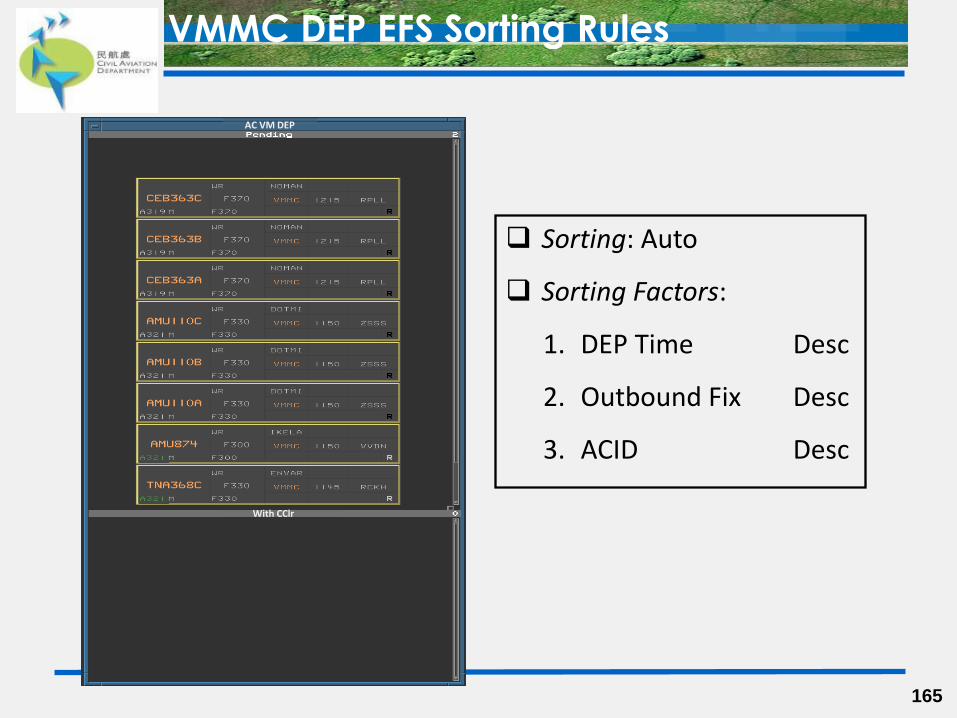
VMMC DEP EFS Sorting Rules
165
Sorting: Auto
Sorting Factors:
1. DEP Time Desc
2. Outbound Fix Desc
3. ACID Desc
AC VM DEP
With CClr

Terminal AC (TA)
166
Inbound & OVF In
posting/suppression rules of pending EFS
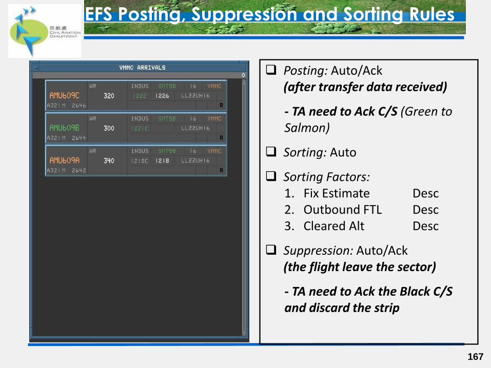
EFS Posting, Suppression and Sorting Rules
167
Posting: Auto/Ack (after transfer data received)
- TA need to Ack C/S (Green to Salmon)
Sorting: Auto
Sorting Factors: 1. Fix Estimate Desc 2. Outbound FTL Desc 3. Cleared Alt Desc
Suppression: Auto/Ack (the flight leave the sector)
- TA need to Ack the Black C/S and discard the strip
168
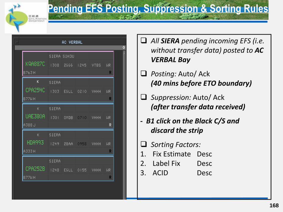
Pending EFS Posting, Suppression & Sorting Rules
All SIERA pending incoming EFS (i.e. without transfer data) posted to AC VERBAL Bay
Posting: Auto/ Ack (40 mins before ETO boundary)
Suppression: Auto/ Ack (after transfer data received)
- B1 click on the Black C/S and discard the strip
Sorting Factors: 1. Fix Estimate Desc 2. Label Fix Desc 3. ACID Desc
K
169
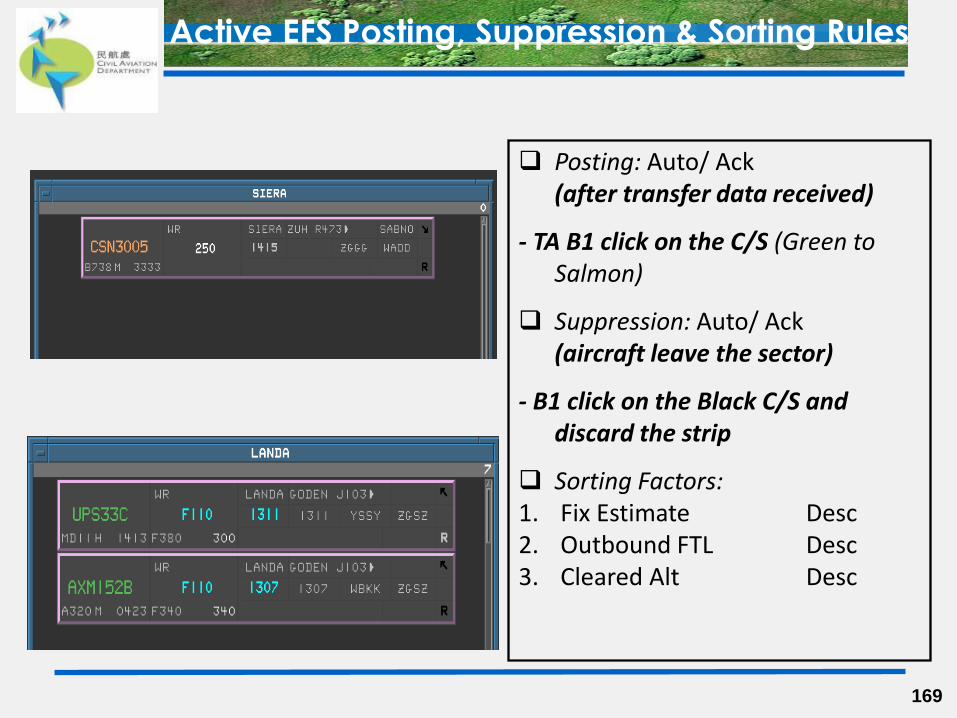
Active EFS Posting, Suppression & Sorting Rules
Posting: Auto/ Ack (after transfer data received)
- TA B1 click on the C/S (Green to Salmon)
Suppression: Auto/ Ack (aircraft leave the sector)
- B1 click on the Black C/S and discard the strip
Sorting Factors: 1. Fix Estimate Desc 2. Outbound FTL Desc 3. Cleared Alt Desc
Permanent Fault Containment
170
171
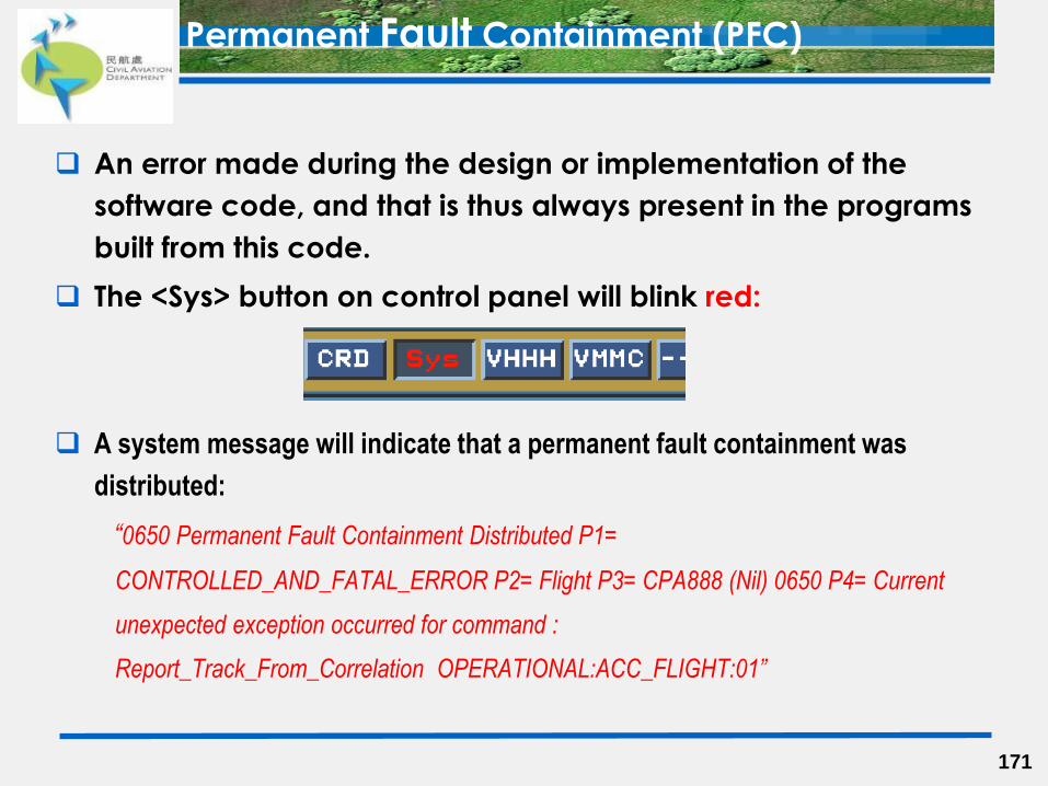
An error made during the design or implementation of the
software code, and that is thus always present in the programs
built from this code.
The <Sys> button on control panel will blink red:
A system message will indicate that a permanent fault containment was
distributed:
“0650 Permanent Fault Containment Distributed P1=
CONTROLLED_AND_FATAL_ERROR P2= Flight P3= CPA888 (Nil) 0650 P4= Current
unexpected exception occurred for command :
Report_Track_From_Correlation OPERATIONAL:ACC_FLIGHT:01”
Permanent Fault Containment (PFC)
172
The flight is marked as erroneous, and no transactions can be
made to the flight. Any attempt to interact with the flight will
result on an
“Error: Unable to complete transaction" message
The flight remains associated, and will remain associated in
the system until the system automatically deletes the
erroneous flight or when the user manually deletes the fault
contained flight. The system is monitored for erroneous flights
periodically.
Permanent Fault Containment (PFC) (conti.)
173
Assistant can recreate a current flight plan and attempt to
re-associate the flight by the following steps:
1) Mark down the original SSR code.
2) Manually create a new FPL (do not use ‘COPY’ function) by
retrieving the details from FPL page of the erroneous flight.
3) Cancel the erroneous FPL.
4) Issue a clearance for the new FPL:
For HK / Macao outbound flight
– assign the original SSR code and convert current clearance in
PClr page.
For inbound and overfly flight
– carry out input of BDRY EST with the original SSR code.
Permanent Fault Containment (PFC) (conti.)

174