
AC Circuits and Power Systems in...
30
Transcript of AC Circuits and Power Systems in...


AC Circuits and Power Systems in Practice

Graeme Vertigan
AC Circuits and Power Systems in Practice

This edition first published 2018© 2018 John Wiley & Sons Ltd
All rights reserved. No part of this publication may be reproduced, stored in a retrieval system, or transmitted, in any form or by any means, electronic, mechanical, photocopying, recording or otherwise, except as permitted by law. Advice on how to obtain permission to reuse material from this title is available at http://www.wiley.com/go/permissions.
The right of Graeme Vertigan to be identified as the author of this work has been asserted in accordance with law.
Registered OfficesJohn Wiley & Sons, Inc., 111 River Street, Hoboken, NJ 07030, USAJohn Wiley & Sons Ltd, The Atrium, Southern Gate, Chichester, West Sussex, PO19 8SQ, UK
Editorial OfficeThe Atrium, Southern Gate, Chichester, West Sussex, PO19 8SQ, UK
For details of our global editorial offices, customer services, and more information about Wiley products visit us at www.wiley.com.
Wiley also publishes its books in a variety of electronic formats and by print‐on‐demand. Some content that appears in standard print versions of this book may not be available in other formats.
Limit of Liability/Disclaimer of WarrantyWhile the publisher and authors have used their best efforts in preparing this work, they make no representations or warranties with respect to the accuracy or completeness of the contents of this work and specifically disclaim all warranties, including without limitation any implied warranties of merchantability or fitness for a particular purpose. No warranty may be created or extended by sales representatives, written sales materials or promotional statements for this work. The fact that an organization, website, or product is referred to in this work as a citation and/or potential source of further information does not mean that the publisher and authors endorse the information or services the organization, website, or product may provide or recommendations it may make. This work is sold with the understanding that the publisher is not engaged in rendering professional services. The advice and strategies contained herein may not be suitable for your situation. You should consult with a specialist where appropriate. Further, readers should be aware that websites listed in this work may have changed or disappeared between when this work was written and when it is read. Neither the publisher nor authors shall be liable for any loss of profit or any other commercial damages, including but not limited to special, incidental, consequential, or other damages.
Library of Congress Cataloging‐in‐Publication Data
Names: Vertigan, Graeme, 1956– author.Title: AC circuits and power systems in practice / by Mr. Graeme Vertigan.Description: Hoboken, NJ, USA : Wiley, [2017] | Includes bibliographical references and index. |Identifiers: LCCN 2017026963 (print) | LCCN 2017028362 (ebook) | ISBN 9781118924600 (pdf) | ISBN 9781118924617 (epub) | ISBN 9781118924594 (cloth)Subjects: LCSH: Electric circuits–Alternating current. | Electric power systems.Classification: LCC TK1141 (ebook) | LCC TK1141 .V47 2017 (print) | DDC 621.31/33–dc23LC record available at https://lccn.loc.gov/2017026963
Cover design: WileyCover image: Graeme Vertigan
Set in 10/12pt Warnock by SPi Global, Pondicherry, India
10 9 8 7 6 5 4 3 2 1

For Louise


vii
Preface xiiiAcknowledgements xvii
Part I 1
1 Power Systems: A General Overview 31.1 Three‐phase System of AC Voltages 31.2 Low Voltage Distribution 61.3 Examples of Distribution Transformers 81.4 Practical Magnitude Limits for LV Loads 101.5 Medium Voltage Network 111.6 Transmission and Sub‐Transmission Networks 241.7 Generation of Electrical Energy 321.8 Sources 41 Further Reading 41
2 Review of AC Circuit Theory and Application of Phasor Diagrams 432.1 Representation of AC Voltages and Currents 432.2 RMS Measurement of Time Varying AC Quantities 442.3 Phasor Notation (Phasor Diagram Analysis) 452.4 Passive Circuit Components: Resistors, Capacitors and Inductors 492.5 Review of Sign Conventions and Network Theorems 552.6 AC Circuit Analysis Examples 612.7 Resonance in AC Circuits 742.8 Problems 832.9 Practical Experiment 88
3 Active Power, Reactive Power and Power Factor 913.1 Single‐Phase AC Power 913.2 Active Power 923.3 Reactive Power 933.4 Apparent Power or the volt‐amp Product, S 963.5 Three‐Phase Power 97
Contents
Contentsviii
3.6 Power Factor 993.7 Power Factor Correction 1003.8 Typical Industrial Load Profiles 1053.9 Directional Power Flows 1073.10 Energy Retailing 1103.11 Problems 111
4 Magnetic Circuits, Inductors and Transformers 1154.1 Magnetic Circuits 1154.2 Magnetic Circuit Model 1164.3 Gapped Cores and Effective Permeability 1194.4 Inductance Calculations 1204.5 Core Materials 1214.6 Magnetising Characteristics of GOSS 1224.7 Energy Stored in the Air Gap 1254.8 EMF Equation 1264.9 Magnetic Circuit Topologies 1274.10 Magnetising Losses 1294.11 Two‐Winding Transformer Operation 1314.12 Transformer VA Ratings and Efficiency 1334.13 Two‐Winding Transformer Equivalent Circuit 1344.14 The Per‐Unit System 1374.15 Transformer Short‐Circuit and Open‐Circuit Tests 1384.16 Transformer Phasor Diagram 1404.17 Current Transformers 142 4.18 Problems 1444.19 Sources 153
5 Symmetrical Components 1555.1 Symmetrical Component Theory 1565.2 Sequence Networks and Fault Analysis 1605.3 Network Fault Connections 1635.4 Measurement of Zero‐sequence Components (Residual Current
and Voltage) 1705.5 Phase‐to‐Ground Fault Currents Reflected from a Star to a Delta
Connected Winding 1715.6 Sequence Components Remote from a Fault 1735.7 Problems 175 5.8 Sources 185
6 Power Flows in AC Networks 1876.1 Power Flow Directions 1886.2 Synchronous Condenser 1886.3 Synchronous Motor 1916.4 Generalised Power Flow Analysis 1926.5 Low X/R Networks 1976.6 Steady State Transmission Stability Limit 201
Contents ix
6.7 Voltage Collapse in Power Systems 2026.8 Problems 207 6.9 Sources 209
Part II 211
7 Three‐Phase Transformers 2137.1 Positive and Negative Sequence Impedance 2137.2 Transformer Zero‐Sequence Impedance 2197.3 Transformer Vector Groups 2217.4 Transformer Voltage Regulation 2227.5 Magnetising Current Harmonics 2287.6 Tap‐changing Techniques 2337.7 Parallel Connection of Transformers 2457.8 Transformer Nameplate 2497.9 Step Voltage Regulator 2517.10 Problems 264 7.11 Sources 272
8 Voltage Transformers 2738.1 Inductive and Capacitive Voltage Transformers 2738.2 Voltage Transformer Errors 2768.3 Voltage Transformer Equivalent Circuit 2818.4 Voltage Transformer ‘Error Lines’ 2848.5 Re‐rating Voltage Transformers 2888.6 Accuracy Classes for Protective Voltage Transformers 2898.7 Dual‐Wound Voltage Transformers 2928.8 Earthing and Protection of Voltage Transformers 2928.9 Non‐Conventional Voltage Transformers 2978.10 Problems 299 8.11 Sources 301
9 Current Transformers 3039.1 CT Secondary Currents and Ratios 3049.2 Current Transformer Errors and Standards 3069.3 IEEE C57.13 Metering Class Magnitude and Phase Errors 3099.4 Current Transformer Equivalent Circuit 3129.5 Magnetising Admittance Variation and CT Compensation
Techniques 3159.6 Composite Error 3199.7 Instrument Security Factor for Metering CTs 3229.8 Protection Current Transformers 3249.9 Inter‐Turn Voltage Ratings 3379.10 Non‐Conventional Current Transformers 3389.11 Problems 341 9.12 Sources 349

Contentsx
10 Energy Metering 35110.1 Metering Intervals 35310.2 General Metering Analysis using Symmetrical Components 36110.3 Metering Errors 36710.4 Ratio Correction Factors 37310.5 Reactive Power Measurement Error 37810.6 Evaluation of the Overall Error for an Installation 37910.7 Commissioning and Auditing of Metering Installations 38110.8 Problems 383 10.9 Sources 388
11 Earthing Systems 39111.1 Effects of Electricity on the Human Body 39111.2 Residual Current Devices 39911.3 LV Earthing Systems 40211.4 LV Earthing Systems used Worldwide 41311.5 Medium Voltage Earthing Systems 41311.6 High Voltage Earthing 42311.7 Exercise 42311.8 Problems (Earthing Grid Design) 425 11.9 Sources 434
12 Introduction to Power System Protection 43712.1 Fundamental Principles of Protection 43712.2 Protection Relays 43812.3 Primary and Backup Protection (Duplicate Protection) 43912.4 Protection Zones 44112.5 Overcurrent Protection 44312.6 Differential Protection 45112.7 Frame Leakage and Arc Flash Busbar Protection 46212.8 Distance Protection (Impedance Protection) 46412.9 Problems 469 12.10 Sources 475
13 Harmonics in Power Systems 47713.1 Measures of Harmonic Distortion 47913.2 Resolving a Non‐linear Current or Voltage into its Harmonic Components
(Fourier Series) 48013.3 Harmonic Phase Sequences 48413.4 Triplen Harmonic Currents 48713.5 Harmonic Losses in Transformers 48713.6 Power Factor in the Presence of Harmonics 49213.7 Management of Harmonics 49513.8 Harmonic Standards 50413.9 Measurement of Harmonics 51413.10 Problems 51513.11 Sources 519

Contents xi
14 Operational Aspects of Power Engineering 52114.1 Device Numbers 52114.2 One Line Diagram (OLD) 52314.3 Switchgear Topologies 52614.4 Switching Plans, Equipment Isolation and Permit to Work Procedures 53714.5 Electrical Safety 54214.6 Measurements with an Incorrectly Configured Multimeter 549 14.7 Sources 551
Index 553


xiii
This book is written as a practical power engineering text for engineering students and recent graduates. It contains more than 400 illustrations and is designed to provide the reader with a broad introduction to the subject and to facilitate further study. Many of the examples included come from industry and are not normally covered in under-graduate syllabi. They are provided to assist in bridging the gap between tertiary study and industrial practice, and to assist the professional development of recent graduates. The material presented is easy to follow and includes both mathematical and visual representations using phasor diagrams. Problems included at the end of most chapters are designed to walk the reader through practical applications of the associated theory.
The text is divided into two parts. The first (Chapters 1 – 6) is primarily intended for undergraduate students. It includes a general overview of the power system, AC circuit theory, network theorems and phasor analysis, in addition to a discussion of active and reactive power, magnetic circuits and an introduction to current and voltage trans-former operation. Part 1 concludes with a discussion of symmetrical component theory and the parameters affecting the flow of power in AC networks, including the phenom-enon of voltage collapse.
Chapter 1 provides a general overview of low, medium and high voltage power sys-tems, including the changes to the generation profile presently occurring and their implications for future network development.
Chapter 2 introduces RMS quantities and phasor representation of alternating volt-ages and currents. Elementary relationships between the voltage and currents in resis-tors, capacitors and inductors are derived and represented as phasor quantities. This chapter demonstrates the use of phasor diagrams as a tool for analysing complex cir-cuits and for gaining a visual insight into their operation. It also reviews voltage and current sign conventions, Kirchhoff ’s current and voltage laws and their application to the principle of superposition, as well as Thévenin and Norton’s Theorems. Series and parallel resonant circuits are also introduced, together with the concept of the quality factor, Q and its application to resonant circuits.
Chapter 2 also contains several phasor analysis examples, including balancing the load of a single‐phase induction furnace across three phases, the operation of a phase sequence indicator, power factor correction and capacitive voltage support for an inductive load.
The concepts of active power, reactive power and power factor are explained in Chapter 3, together with a discussion of the electrical characteristics of large and small commercial loads. The need for power factor correction (PFC) is considered together
Preface

Prefacexiv
with a practical method of sizing PFC equipment for a given load. The chapter con-cludes with a general introduction to energy retailing, including transmission and distribution loss factors and maximum demand limits and charges.
Chapter 4 introduces the idea of a magnetic circuit and its application to voltage and current transformers. The properties of magnetic materials are considered, including air gaps necessary in reactor design. The constant flux model of a two‐winding transformer and its equivalent circuit are developed, and per‐unit quantities are introduced through numerical examples. Finally, the apparent difference between current and voltage transformers is explained. Examples include the reactor design and the determination of the Q factor, the magnetic analysis of an electromagnetic sheet‐metal folding machine, and transformer operation from the point of view of mutual coupling.
Symmetrical component theory is introduced in Chapter 5, with the concept of posi-tive, negative and zero‐sequence components, sequence networks and sequence impedances. Sequence network connections are analysed for common system faults, and their use in determining the primary phase currents of a transformer with a faulted secondary is described. Examples include a method of locating faults in MV feeders as well as the design of an electronic negative sequence filter.
Chapter 6 considers the flow of active and reactive power in AC networks, including a discussion of the degree of coupling between them and the network parameters influ-encing each. The phenomenon of voltage collapse in networks is also discussed as well as steps generally taken by authorities to prevent one. Examples include voltage drops in transmission and distribution networks as functions of the system X/R ratio, and the practical application of phase shifting transformers to control active and reactive power flows in transmission networks.
The second part of the book (Chapters 7–14) contains material appropriate to final year students and recent engineering graduates and is written to assist a rapid integration into the engineering profession. It introduces the practical application of engineering standards and compares IEEE standards published in the USA with those published by the IEC in Europe.
Part 2 begins in Chapter 7 with a detailed discussion of three‐phase transformers, including impedance calculations and the influence of core architectures and winding arrangements on positive, negative and zero‐sequence impedances. Vector grouping, transformer voltage regulation, magnetising characteristics and zero‐sequence imped-ances are examined, as are tap‐changing techniques and the parallel operation of trans-formers. Examples include a detailed operational analysis of step voltage regulators and phase shifting transformers.
Chapter 8 examines the characteristics of both inductive and capacitive voltage transformers. It begins with a detailed examination of the inherent phase and magni-tude errors and presents equations relating them to elements within the transformer equivalent circuit and the applied burden. IEEE and IEC voltage transformer standards are compared, with particular reference to ratings and accuracy classes. A simple method for error conversion between different burdens is presented, together with a discussion of the use of voltage transformers in protection and metering applications. The definitions of earth fault factor, effective earthing and the phenomenon of ferro‐resonance are discussed. Finally, the operating principles of non‐conventional voltage transformers are briefly examined.

Preface xv
Chapter 9 analyses the operating principles and limitations of magnetic current trans-formers in metering and protection applications. The relevant IEEE and IEC standards are again compared. Magnitude and phase errors as well as ratio and transformer correc-tion factors are defined and evaluated from elements within the CT equivalent circuit including the connected burden. Magnetising admittances and saturation effects are discussed and the concept of composite error and methods of measuring it in protection cores are described. The significance of the knee point voltage and accuracy limit factors in protection CTs are explained and the various protection classes defined in each standard are also considered. The derivation of the over‐current ratio curve from the magnetising characteristic is described together with the series and parallel CT connections used in both protection and metering applications. Finally, non‐conventional current transformers are introduced together with a discussion of their operating principles. Examples include the design of a simple current transformer test set, and the evaluation of CT errors from magnetising admittance data.
Three‐phase energy metering circuits are described in Chapter 10. The concept of a metering interval is introduced and the advantages offered by static meters as com-pared to accumulation meters are explained. Both the three‐element and two‐element approaches to three‐phase metering are analysed, including Blondel’s theorem. Several non‐Blondel compliant metering topologies are also described. This chapter considers the response of these circuits to negative and zero‐sequence components and the degree of error they introduce. It also evaluates the overall metering error as a result of the inherent errors in current and voltage transformers. The final correction factor as defined in the IEEE standard is described and is related to the transformer correction factors for the associated voltage and current transformers. Examples include a com-parison of MV and LV metering across a transformer, the recovery of the correct metering data from a faulted two‐element metering installation and the analysis of a non‐Blondel compliant metering topology.
Chapter 11 provides an introduction to the various earthing systems used in MV and LV electricity networks. It begins with an examination of the effects of electric current on the human body, which determine to a large extent the operational requirements of earthing systems. Chapter 11 continues with a discussion of the TT, TN and IT low voltage earthing systems, as well as impedance earthed and un‐earthed neutrals used in medium voltage systems, including resonant earthing. An example of an earth grid design is presented according to the process outlined in the American standard IEEE 80.
Power system protection is introduced in Chapter 12, beginning with a general dis-cussion of protection principles including primary and backup protection, check relays, zones of protection, discrimination and protection reliability. It concludes with a discussion of overcurrent, restricted earth fault, differential transformer protection and busbar protection systems as well as impedance protection schemes used throughout the transmission network. The class of current transformers required for each scheme is explained. Examples include the detection of a cable fault on a resonant earthed system, the interpretation of inverse time‐current characteristics for establishing grading margins and the operation of a high impedance bus protection scheme in the presence of CT saturation.
Chapter 13 considers the issue of harmonics in power systems. It describes the reso-lution of a periodic waveform into its harmonic components using Fourier series and the simplifications that can be made due to waveform symmetry. Common harmonic

Prefacexvi
measures including total harmonic distortion, total demand distortion, crest factor and transformer K ratings are defined, as are positive, negative and zero‐sequence (triplen) harmonics. The adverse effects of triplen harmonic currents are discussed, as are meth-ods used to contain them. The effects of harmonic losses in transformers are described and the harmonic loss factor is used to calculate a transformer de‐rating factor appro-priate to the load harmonic spectrum. The power factor definition is amended in the presence of harmonics to allow for the resulting harmonic VAr flow. Harmonic filters and harmonic cancellation techniques are discussed and the approaches taken under IEC and IEEE standards to harmonic management are described, together with the assessment of a distorting load prior to network connection.
Finally, Chapter 14 brings together several operational topics of interest to graduate engineers. These include a discussion of the one line diagram and device numbers used to designate primary and secondary items of equipment, followed by a discussion of common switchgear and busbar topologies including suggestions for optimal busbar arrangements. Switching plans, equipment isolation and permit to work procedures are discussed as well as workplace safety and the observation of limits of approach relative to live equipment. Arc flash injury and the selection of arc rated personal protective equipment are also discussed.
Graeme VertiganJanuary 2017

xvii
Writing this book would not have been possible without the assistance, encouragement and advice of many colleagues, and the support of numerous organisations. I would like to acknowledge the assistance provided by Andrew Halley, Matthew and Chris Simmons, Jimmy Chong, Dominik Ziomek, Dan Sauer, Anasthasie Sainvilus, Daniela Chiaramonte and John Thierfelder in reviewing various chapters and assisting with copyright permissions.
In particular, I would like to thank Dr David Lewis and Mr Tim Sutton for their atten-tion to detail, both technical and grammatical, and their patience in reviewing each chapter, usually more than once, and finally to David Vertigan for his skill and dedication in preparing the illustrations.
I would also like to thank the International Electrotechnical Commission (IEC) for permission to reproduce information from its International Standards. All such extracts are copyright of IEC, Geneva, Switzerland. All rights reserved. Further information on the IEC is available from www.iec.ch. IEC has no responsibility for the placement and context in which the extracts and contents are repro-duced by the author, nor is the IEC in any way responsible for the other content or accuracy herein.
The author is also grateful to the Institute of Electrical and Electronics Engineers (IEEE) for permission to reproduce material from IEEE Standards. All such extracts are copyright of the IEEE, New Jersey, USA. The IEEE accepts no responsibility for the use of its material nor is it in any way responsible for the other content.
The Eaton Corporation of the USA has kindly provided illustrations and ongoing assistance with the preparation of material relating to its Cooper step regulators, for which I would like to express my appreciation.
Schneider Electric has made available material from its Cahiers Techniques series of industrial publications for use in this book, for which I would like to express my sincere thanks.
Finally, I would also like to extend my appreciation to the following companies and individuals for their assistance and use of materials:
● Lynda O’Meara of SAI Global on behalf of Standards Australia, Sydney ● Denis Berry of the National Fire Prevention Association, Quincy, Massachusetts ● Hughes Zhang of the Guizhou Changzheng Electric Co., Ltd, Peoples Republic of China ● Mark Ridgway of AEM Cores, Gillman, South Australia
Acknowledgements

Acknowledgementsxviii
● Romano Sartori of Mitre Core Technologies, Germiston South, Republic of South Africa ● Alan Bottomley the Tasmanian Inventor of the Magnabend Electromagnetic Sheet
Metal Bending Machine, Hobart, Tasmania ● The Beckwith Electric Company, Largo, Florida ● The International Energy Agency, Paris, France
G. Vertigan

1
Part I

AC Circuits and Power Systems in Practice, First Edition. Graeme Vertigan. © 2018 John Wiley & Sons Ltd. Published 2018 by John Wiley & Sons Ltd.
3
1
In this chapter we present an overview of the structure of a modern power system, from the low voltage distribution networks with which we are partly familiar, to the high voltage transmission system bringing energy from remote electrical generators.
Before we begin, we need to define the different potentials which we will encounter throughout the power system. We use abbreviations to denote different voltage levels, as outlined in Table 1.1. However, as is often the case, there appears to be no universally accepted definition, so you may see slightly different definitions used elsewhere.
1.1 Three‐phase System of AC Voltages
The alternating voltage distributed to our homes has (ideally) a sinusoidal form. Sinusoidal waveforms are chosen because, when pure, they contain only one frequency; that is, they should contain no supply frequency harmonics (i.e. multiples of the fundamental frequency). Unfortunately, due to the increasing number of non‐linear loads connected to the power system and the non‐sinusoidal currents they consume, harmonic voltage distortion is becoming an increasing problem. This is particularly so in the LV network and, as a result, the AC voltage we receive often contains some harmonic distortion. However, despite this it is still approximately sinusoidal.
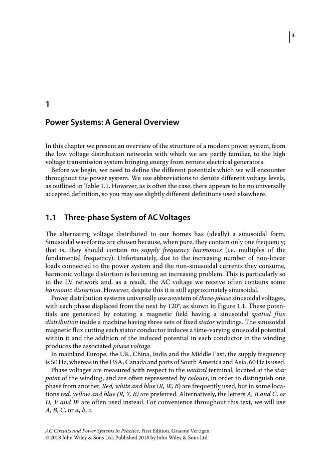
Power distribution systems universally use a system of three‐phase sinusoidal voltages, with each phase displaced from the next by 120°, as shown in Figure 1.1. These poten-tials are generated by rotating a magnetic field having a sinusoidal spatial flux distribution inside a machine having three sets of fixed stator windings. The sinusoidal magnetic flux cutting each stator conductor induces a time‐varying sinusoidal potential within it and the addition of the induced potential in each conductor in the winding produces the associated phase voltage.
In mainland Europe, the UK, China, India and the Middle East, the supply frequency is 50 Hz, whereas in the USA, Canada and parts of South America and Asia, 60 Hz is used.
Phase voltages are measured with respect to the neutral terminal, located at the star point of the winding, and are often represented by colours, in order to distinguish one phase from another. Red, white and blue (R, W, B) are frequently used, but in some loca-tions red, yellow and blue (R, Y, B) are preferred. Alternatively, the letters A, B and C, or U, V and W are often used instead. For convenience throughout this text, we will use A, B, C, or a, b, c.
Power Systems: A General Overview

AC Circuits and Power Systems in Practice4
Low voltage customers are generally supplied from a three‐phase distribution transformer, although single‐phase transformers are often used for smaller loads. Figure 1.2a shows the transformer winding arrangement most commonly used. The primary windings or the medium voltage (MV) windings are delta connected (Δ) and are supplied from the three‐conductor MV bus. The secondary or the low voltage (LV) windings are connected in a wye (Y) or star configuration, within which the LV potentials are induced.
Table 1.1 Voltage definitions.
LV (low voltage) <1000 V ACMV (medium voltage) 1–35 kV ACHV (high voltage) 35–230 kVEHV (extra high voltage) >230 kV
400
300
200
100
–100
–200
–300
–400
0
Volt
age
(vo
lts)
–5 0 5 10
Time (ms)
Va Vb Vc
15 20 25 30
Figure 1.1 Three‐phase alternating voltages.
A
(a) (b)
a
a
b
120°
120°
230 volts
b
c
c
n
B
C
MV windings(delta connected)
LV windings(star connected)
n
Figure 1.2 (a) Typical distribution transformer winding arrangement (b) Low voltage representation.
Power Systems: A General Overview 5
Each low voltage phase is referenced to a common neutral terminal (n), and while the three‐phase voltages each have the same magnitude, they differ from one another in phase by 120°. The magnitude of the phase voltages varies throughout the world, but in many countries a phase potential around 230 V is used.
The sequence in which the phase voltages reach their maximum value is important. Just as there are only two possible rotational directions for the magnetic field within a machine, (clockwise and anticlockwise), there are also only two possible phase sequences; ABC and ACB. The phase sequence of the supply determines the direction of rotation of polyphase motors. Reversing the phase sequence of a three‐phase supply, by swapping any two phases, will thus reverse the direction of rotation of any machine connected to it.
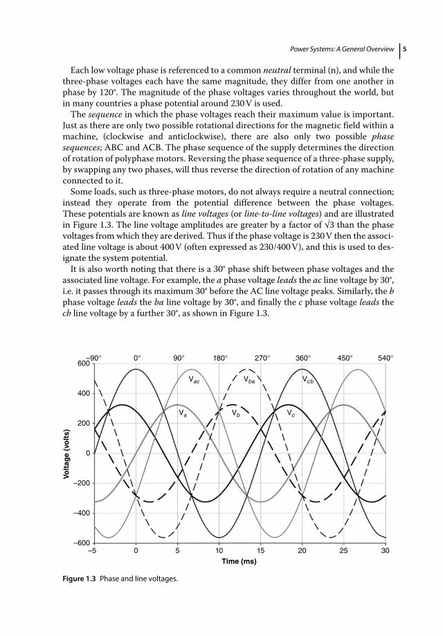
Some loads, such as three‐phase motors, do not always require a neutral connection; instead they operate from the potential difference between the phase voltages. These potentials are known as line voltages (or line‐to‐line voltages) and are illustrated in Figure 1.3. The line voltage amplitudes are greater by a factor of √3 than the phase voltages from which they are derived. Thus if the phase voltage is 230 V then the associ-ated line voltage is about 400 V (often expressed as 230/400 V), and this is used to des-ignate the system potential.
It is also worth noting that there is a 30° phase shift between phase voltages and the associated line voltage. For example, the a phase voltage leads the ac line voltage by 30°, i.e. it passes through its maximum 30° before the AC line voltage peaks. Similarly, the b phase voltage leads the ba line voltage by 30°, and finally the c phase voltage leads the cb line voltage by a further 30°, as shown in Figure 1.3.
–5–600
–400
–200
0
200
400
600–90° 0° 90°
Vac Vba
Vc
Vcb
VbVa
180° 270° 360° 450° 540°
0 5 10 15
Time (ms)
Volt
age
(vo
lts)
20 25 30
Figure 1.3 Phase and line voltages.

AC Circuits and Power Systems in Practice6
1.2 Low Voltage Distribution
Most European countries use 230/400 V for LV distribution, or in some cases 240/415 V instead. The majority of residential customers receive a single‐phase supply (i.e. one phase conductor and the neutral) which terminate at the customer’s premises via a service drop (or service connection). These conductors frequently run from the overhead LV network, to a roof or wall mount on the customer’s dwelling, and from there to a service fuse, which can be used for isolation purposes. The supply cables or customer mains then run via the electricity meter to the customer’s switchboard. Customers who have an underground LV supply are likely to have mains running from a distribution kiosk on the street to their premises.
Commercial and industrial low voltage customers in Europe, Australia and New Zealand are usually provided with a 230/400 V three‐phase supply (three‐phase conductors and the neutral) from an LV transformer arrangement like that in Figure 1.4. These customers may therefore run single‐phase loads between any phase conductor and neutral, as well as line connected three‐phase loads. The four‐wire wye (or star) 230/400 V connection is probably the most com-mon LV distribution arrangement, and it is used in many countries worldwide.
In some countries, large commercial or industrial LV loads can also be supplied with a three‐wire 400/690 V supply. In the USA and Canada, however, residential customers are often supplied with two voltages: 120 V for lighting and low‐current loads and 240 V for larger single‐phase loads, such as water heaters or power tools. These voltages are often generated within the same single‐phase transformer using a centre‐tapped winding as shown in Figure 1.5. The centre tap (or neu-tral terminal) is earthed (connected to ground potential) and therefore the potentials of the two active conductors are 180° apart, that is, they are symmetrical with respect to the earthed neutral conductor. Such single‐phase transformers are usually relatively small, (<100 kVA) and generally supply fewer than ten residences.
In older parts of North America other customers are supplied with a three‐phase four‐wire supply from a delta connected sec-ondary winding (Figure 1.6), where one winding has been fitted with a grounded centre tap. This arrangement provides two 120 V supplies for lighting and low‐current loads, while also providing a three‐phase 240 V supply for high‐ current loads such as water and space heating. Because one phase lies 208 V away from ground while the others are only 120 V from it, this arrangement is known as a high leg delta connection.
One advantage of the high leg delta arrangement is that, if necessary, it can be provided in an open delta configuration from two single‐phase transformers rather than three, as shown
c
n
ab
Figure 1.4 Typical 230/400 V three‐phase supply.
a1
n
a2
Figure 1.5 Single‐phase transformer using a centre‐tapped winding.
c
na
b
Figure 1.6 Three‐phase four‐wire supply from a delta connected secondary winding.

Power Systems: A General Overview 7
in Figure 1.7; however, the maximum three‐phase load that can be applied in this situation is only 1/√3 or 57.7% of the rating with three transformers present. In other parts of the USA, resi-dential customers are provided with a three‐phase dual‐voltage supply derived from a delta/wye transformer (Δ/Y) with a phase voltage of 120 V and a line voltage of 208 V.
Commercial and industrial customers in the USA frequently require a three‐phase supply with line voltages greater than either 208 or 240 V; for these a conventional delta/wye (Δ/Y) connected transformer is used, having phase/line voltages of either 265/460 V or 277/480 V.
Finally, there is one LV winding arrangement that has historically been used in the USA for mainly three‐phase loads, which deserves special comment. It is known as a corner grounded delta, or a grounded b phase system (Figure 1.8). This configuration is no longer used in new installations but it was used for many years in irrigation and oil pumping applications and is occasionally still in use today. One advantage of the corner grounded delta is its ability to continue to supply load when operating as an open delta, as described above. This feature provided the possibility of doing maintenance on each single‐phase transformer in turn, from a three‐phase bank, without having to disconnect the entire load. Today, three‐phase transformers are more reliable and are not assembled from single‐phase devices, and therefore the corner grounded delta has lost its popularity.
There are some disadvantages associated with this configuration that should also be mentioned. Firstly, for reasons of safety it is necessary to identify the grounded phase at all points along the line. Secondly, a phase‐to‐ground fault in a corner grounded delta network is essentially a phase‐to‐phase fault, and in 480 V systems quite large fault currents can flow through one pole of the circuit breaker. Interrupting such single‐phase fault currents can be challenging, especially if the circuit breaker chosen does not have a sufficiently high single pole interruption rating.
Many moulded case circuit breakers used in LV applications have a considerably higher three‐phase fault interruption capacity than a single‐phase one. A bolted phase‐to‐phase fault (i.e. one with zero impedance) can generate as much as 87% of the current available in a three‐phase fault, and the breaker chosen must be capable of clearing this level of fault current. Not all moulded case circuit breakers have the ability to interrupt single‐phase currents of this magnitude. Circuit breakers used in corner grounded delta networks must therefore be carefully chosen with the necessary single pole interruption capacity in mind.
1.2.1 Voltage Tolerance
The LV distribution voltage levels mentioned above are all subject to a prescribed tolerance. This is partly because the MV system voltage fluctuates as a function of changes in the reflected LV load. Although the MV system potential is regulated by the HV/MV transformer (through the use of an on‐load tap‐changer), voltage drops that
c
n
a
b
Figure 1.7 Open delta configuration from two single‐phase transformers.
c
a
b
Figure 1.8 Corner grounded delta, or a grounded b phase system.

AC Circuits and Power Systems in Practice8
occur throughout the MV network, as well as within the MV/LV transformer itself, are directly reflected into the LV network since the MV/LV transformer usually does not have on‐load tap‐change facilities, that is, it operates at a fixed transformation ratio.
The International Electrotechnical Commission (IEC) standard IEC 60038, entitled ‘Standard Voltages’ defines a ±10% tolerance1 on the nominal supply voltage for 50 Hz LV systems, and +10% −5% tolerance1 for 60 Hz systems. It also allows a 3% voltage drop for lighting circuits and 5% for all other circuits within a customer’s premises. Collectively this means that for 50 Hz systems the Utilisation Voltage seen at outlets within a customer’s premises may vary from the nominal voltage by +10% −13% for lighting circuits, and +10% −15% for all other circuits. For 60 Hz systems, the overall tolerance is +10% −8% for lighting circuits and ±10% for all other circuits. Table 1.2 shows the typical ranges of common LV distribution voltages.
1.2.2 Load Balance
It is important that the total connected load is shared almost equally across all three phases, that is, it is balanced. This is generally achieved in a residential distribution system by ensuring that the number of customers connected to each phase is roughly equal, given that residential loads are generally similar and they also have comparable daily load profiles. Whether a small commercial or industrial custom-er’s load is balanced usually depends largely on how well the single‐phase load is distributed, since three‐phase loads, (motors for example) tend to be inherently balanced. On the other hand, very large industrial customers (base load customers) are required to present a balanced load to the network as part of their connection agreements.
1.3 Examples of Distribution Transformers
An engineer can learn much by observing equipment in the field. In particular, reading equipment nameplates can reveal a lot about an installation. We will consider two examples of distribution transformers: Figure 1.9 shows a public pole‐mounted LV
1 These tolerances may vary slightly from one country to another if national standards differ from IEC 60038.
Table 1.2 Typical distribution voltage ranges.
System frequency(Hz)
Nominal voltage
Highest supply or utilisation Voltage
Lowest supply voltage
Lowest utilisation voltage for lighting
Lowest utilisation voltage for other loads
50 230/400 253/440 207/360 200/348 196/34060 120/208 127/220 109/190 106/184 104/18060 230/400 253/440 219/380 212/368 207/360
(IEC 60038, Copyright © 2009 IEC Geneva, Switzerland. www.iec.ch)

Power Systems: A General Overview 9
distribution transformer in China, and Figure 1.10 shows an Australian ground‐mounted distribution transformer enclosure (also known as a pad‐mounted trans-former). The pole‐mounted device is fed from three‐wire 10 kV droppers on the left‐hand pole, while the four‐wire 400 V LV supply leaves the transformer as an aerial bus via the right‐hand pole. MV drop‐out fuses in series with the incoming droppers protect the high voltage side, and exposed LV fuse elements mounted on the LV isolator on the right protect the low‐voltage side. The LV conductors also pass through a set of meter-ing current transformers (in the metal enclosure), so that the energy supplied by this transformer can be measured.
The pad‐mounted transformer enclosure shows little from the outside; internally, however, it is actually a miniature 11 kV:415 V substation. It contains both MV and LV switchgear, located in opposite ends of the enclosure, with the distribution transformer mounted in between. This particular unit is dedicated to one customer and is fed from an underground 11 kV ring main; it supplies a large building on an industrial site. Both the MV and LV cabling is underground, and therefore this installation is aesthetically more pleasing than the pole‐mounted one.
Figure 1.9 A 500 kVA pole‐mounted distribution transformer (China).
Figure 1.10 A 500 kVA ground‐mounted transformer (Australia).

AC Circuits and Power Systems in Practice10
1.4 Practical Magnitude Limits for LV Loads
There are significant advantages in moving to higher potentials for larger loads, particularly the associated reduction in both supply current and electrical losses. This change also permits smaller section conductors to be used throughout the distribution network, which can provide considerable savings. It is for these reasons that commercial and industrial LV customers operate on 400 or 460 V rather than 230 or 120 V.
However, as industrial loads increase in size, eventually a limit is reached where it is no longer economic to provide the service from an LV supply. This limit generally occurs in industries where the site load is considerably larger than that usually found in the public network, for one of the following reasons. Firstly, very large phase currents demand very large supply conductors, which can become expensive, especially if they have to run a considerable distance from the distributor to the customer. Secondly, depending on the available transformer capacity, it may be necessary for the distribution company to install a dedicated transformer to cater for the requirements of particular customers. Thirdly, for particularly large loads and low impedance LV supplies, the prospective fault currents may become too large for conventional LV switchgear (circuit breakers) to handle.
The third point requires further clarification. Moulded case circuit breakers, fre-quently used in LV applications have several current ratings. For the purpose of this discussion we will consider only two: the continuous current rating and the service fault interruption capacity. The continuous current rating is the current that the breaker can continuously carry and interrupt safely; it is the nominal rating of the device (although it may be higher than the current at which the breaker is actually set to trip). The service fault interruption capacity is the value of the (balanced) three‐phase fault current that the breaker is capable of interrupting. This is the practical limit of the ability of the device to clear a downstream three‐phase fault.
The continuous current ratings of LV circuit breakers can be as large as 6000 A, but breakers of this size are generally for special applications. The current rating of LV circuit breakers used in general customer applications seldom exceed around 3200 A, and for these devices the service fault interruption capacity is frequently of the order of 50–70 kA.
A practical limit to the size of an LV load arises when the prospective three‐phase fault current cannot be interrupted by the selected LV circuit breaker. For example, consider a 2.2 MVA Δ/Y distribution transformer delivering 400 V to an LV bus. The rated secondary current for such a transformer is 3175 A (=2.2 MVA/(400 V√3)), so a 3200 A breaker would just suffice in this application (although it is not good engineer-ing practice to operate either the transformer or the circuit breaker continuously at the limit of their ratings).
Assuming that the MV bus impedance is small with respect to that of the transformer, then the latter will limit any three‐phase fault current. As we shall see in a later chapter, the impedance of a transformer (sometimes called the voltage impedance) is usually expressed in per cent, with typical values being 4–20%. The percentage impedance is defined as that fraction of the nominal supply voltage which, when applied to a trans-former with short circuits on all phases, results in the rated current flowing in each phase. Therefore the three‐phase fault current that would flow with the transformer fully excited, can be calculated by dividing the rated current by the transformer’s impedance.