AC Bridge Circuits - Chemeketa Community...
25
AC Bridge Circuits
Transcript of AC Bridge Circuits - Chemeketa Community...
AC Bridge Circuits

Objectives
• Review DC Wheatstone Bridge circuits• Investigate the most common AC Bridge
Circuits.

So Why A Bridge Circuit?• Used for precise measurements of resistance, reactive
components, impedances, temperature, pressure, strain, and other physical quantities (measured or sensed with transducers).
• Present in many expensive real-time monitoring devices where physical quantities are measured or sensed with transducers.
• Present in many expensive component-measuring devices such as inductive-capacitive meters and high-end ohmmeters.
• Bridges are also used to rectify AC signals into DC signals, filters and oscillators (Wien-Bridge), and to eliminate input capacitances in test instruments (oscope x10 probes).

General Properties Of AC Bridge Circuits• AC bridge circuits work on the same basic principle as DC bridge circuits:
that a balanced ratio of impedances (rather than resistances) will result in a "balanced" condition as indicated by the null-detector device.
• Null detectors for AC bridges may be sensitive electromechanical meter movements, oscilloscopes (CRT's), headphones (amplified or unamplified), or any other device capable of registering very small AC voltage levels. (DC meter movements can be used if the AC is rectified). Like DC null detectors, its only required point of calibration accuracy is at zero.
• AC bridge circuits can be of the "symmetrical" type where an unknown impedance is balanced by a standard impedance of similar type on the same side (top or bottom) of the bridge. Or, they can be "nonsymmetrical," using parallel impedances to balance series impedances, or even capacitances balancing out inductances.
• AC bridge circuits often have more than one adjustment, since both impedance magnitude and phase angle must be properly matched to balance.
• Some impedance bridge circuits are frequency-sensitive while others are not. The frequency-sensitive types may be used as frequency measurement devices if all component values are accurately known.

DC Wheatstone Bridge• Recall that the DC Wheatstone Bridge is simply two parallel
resistive voltage dividers connected to a common DC source with the output taken between the junctions of the two dividers, and a ratio developed for the balanced condition when VOUT = 0V (the null detector): R1/R2 = R3/R4
• You may want to review pgs. 266-270 in your textbook.

DC Wheatstone Bridge• When one resistor is made variable, and another is an
unknown value of resistance, the unknown resistance may be determined by adjusting the variable resistor until the bridge is balanced and then calculating the unknown resistance as follows: RUNK = (R2/R1)*R3 where R3 is the variable resistor.

Unbalanced Wheatstone Bridge
• The unbalanced bridge is used to measure some transducer quantities, such as strain, temperature, or pressure.
• The bridge is balanced at a known point, then the amount of deviation, as indicated by the output voltage, indicates the amount of change in the parameter being measured.

Unbalanced Wheatstone BridgeThe value of the parameter being measured can be determined by the amount that the bridge is unbalanced.
Tiny changes in transducer resistance will unbalance the bridge, thereby providing a measurement reading.• For example, if the transducer above is a thermistor,
• ∆Vout = ∆Rtherm(Vs/4R) where R = R2 = R3 = R4
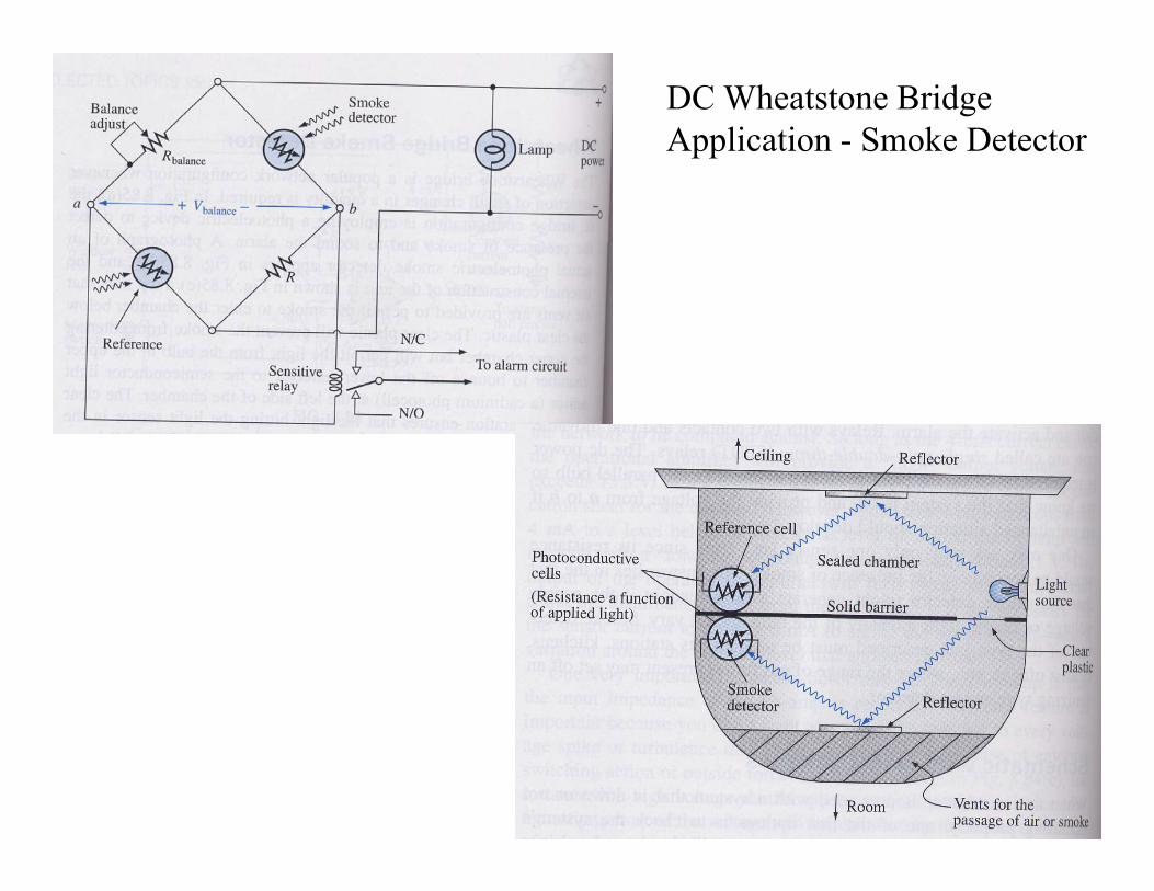
DC Wheatstone Bridge Application - Smoke Detector

AC Wheatstone Bridge• An AC Wheatstone Bridge is similar to a DC Wheatstone
Bridge except for:– Common AC Source.– Resistances R may be replaced by impedances Z.– When measuring impedances, an AC Wheatstone Bridge is often
referred to as a general impedance bridge.
Vs
R2
R3
V
R1
R4
R1
R3
VRunk
Vs
R2
Vs
Z1
VZ3 Zunk
Z2
VZUNK = (Z2/Z1)*Z3 where Z3 is the variable impedance

General AC Bridge Balanced Equation
• When Zx is located in the lower right-hand branch and the bridge is balanced, the unknown impedance Zx is calculated as:
• Note the similarity between this equation and the equation for the DC Wheatstone Bridge.

Common AC Bridge Circuits

Common AC Bridge Circuits
• Can be used to measure the frequency of the source

EXAMPLE 1
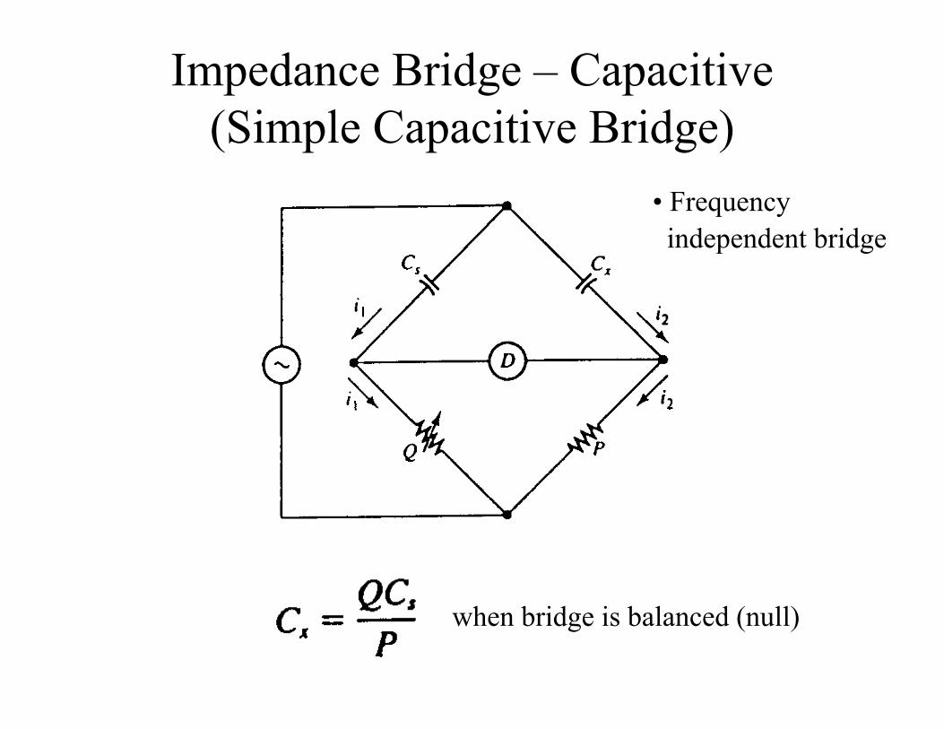
Impedance Bridge – Capacitive(Simple Capacitive Bridge)
when bridge is balanced (null)
• Frequency independent bridge

Series-Resistance Capacitive Bridge
when bridge is balanced (null)
• Frequency independent bridge
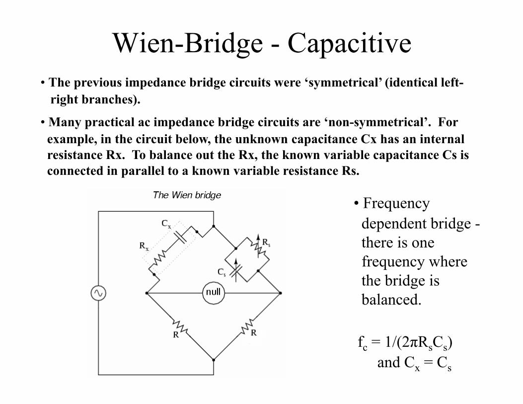
Wien-Bridge - Capacitive• The previous impedance bridge circuits were ‘symmetrical’ (identical left-
right branches).
• Many practical ac impedance bridge circuits are ‘non-symmetrical’. For example, in the circuit below, the unknown capacitance Cx has an internal resistance Rx. To balance out the Rx, the known variable capacitance Cs is connected in parallel to a known variable resistance Rs.
• Frequency dependent bridge -there is onefrequency where the bridge is balanced.
fc = 1/(2πRsCs)and Cx = Cs

Wien-Bridge (cont.)• Like other types of AC Bridge circuits, the Wien-
Bridge circuit is also used for measurement purposes but is also commonly used for notch filters and oscillators.
• When ωCR = 1, Vo(1) = Vo(2) = (1/3)Vin, Vout in-phase with Vin. Vout is then equal to 0V and the bridge is balanced.
• For any values of R and C, there is one frequency where the above conditions will occur.

Wien-Bridge As A Notch Filter• Wien-Bridge acts as a notch filter at one frequency:
• fc = 1/(2πRC) where R2 = R3 = R4 = R5 and C1 = C2
Bode Plot - Wien Bridge 2R = 22.0 kΩ, C = 0.10 μF
-25
-20
-15
-10
-5
00 50 100 150 200 250 300
Frequency (Hz)
Gai
n (d
B)
fc = 1/(2πRC)

Wien-Bridge As A Sine-Wave Generator (or Oscillator)
• Wien-Bridge acts as a sine-wave generator or oscillator at one frequency:
• fc = 1/(2πRC) • The nonlinear resistance of the Lamp stabilizes the gain and prevents sine-wave clipping.
• The positive feedback sustains the sine-wave frequency.

EXAMPLE 2

Maxwell Bridges
• Frequency independent bridge

EXAMPLE 3

EXAMPLE 4• In the capacitance bridge shown above, resistor Q is variable from 500 ohms to 10 kohms, and S ranges from 1 kohm to 3 kohms. P is a standard 1 kohm resistor and Cs is a standard 0.1uF capacitor. Calculate the range of measurement of Cx and rx.
• Cx range:
• Cx(min) = (Qmin*Cs)/P = (500 ohms*0.1uF)/1k = 50 nF
• Cx(max) = (Qmax*Cs)/P = (10k*0.1uF)/1k = 1 uF
• rx(min) = P*S(min)/Q(max) = (1k*1k)/10k = 0.2 ohms
• rx(max) = P*S(max)/Q(min) = (1k*3k)/500 ohms = 6 ohms

Single-Ended AC Bridge• All the AC bridges discussed so far are sometimes
referred to as differential-ended AC bridges because the output of the bridge is floating (not referenced to ground). These types of bridges are very sensitive to bridge changes and susceptible to external noise.
• See ‘Oscilloscope Compensating Probe’ for an example of a Single-Ended AC bridge. A single-ended AC bridge has the output voltage referenced to ground. These types of bridges are not as sensitive to bridge changes compared to differential-ended AC bridges but are less susceptible to external noise.