AC 800M EtherNet/IP DeviceNet Installation - ABB Group · PDF fileAC 800M EtherNet/IP...
80
Power and productivity for a better world TM AC 800M EtherNet/IP DeviceNet Installation System Version 6.0
Transcript of AC 800M EtherNet/IP DeviceNet Installation - ABB Group · PDF fileAC 800M EtherNet/IP...

Power and productivity
for a better worldTM
AC 800MEtherNet/IP DeviceNetInstallation
System Version 6.0


AC 800MEtherNet/IP DeviceNet
Installation
System Version 6.0

NOTICEThis document contains information about one or more ABB products and may include adescription of or a reference to one or more standards that may be generally relevant tothe ABB products. The presence of any such description of a standard or reference to astandard is not a representation that all of the ABB products referenced in this documentsupport all of the features of the described or referenced standard. In order to determinethe specific features supported by a particular ABB product, the reader should consult theproduct specifications for the particular ABB product.
ABB may have one or more patents or pending patent applications protecting the intel-lectual property in the ABB products described in this document.
The information in this document is subject to change without notice and should not beconstrued as a commitment by ABB. ABB assumes no responsibility for any errors thatmay appear in this document.
In no event shall ABB be liable for direct, indirect, special, incidental or consequentialdamages of any nature or kind arising from the use of this document, nor shall ABB beliable for incidental or consequential damages arising from use of any software or hard-ware described in this document.
This document and parts thereof must not be reproduced or copied without written per-mission from ABB, and the contents thereof must not be imparted to a third party nor usedfor any unauthorized purpose.
The software or hardware described in this document is furnished under a license andmay be used, copied, or disclosed only in accordance with the terms of such license. Thisproduct meets the requirements specified in EMC Directive 2004/108/EC and in Low Volt-age Directive 2006/95/EC.
TRADEMARKSAll rights to copyrights, registered trademarks, and trademarks reside with their respec-tive owners.
Copyright © 2003-2014 by ABB. All rights reserved.
Release: August 2014Document number: 9ARD000015-600

9ARD000015-600 5
TABLE OF CONTENTS
About This User ManualGeneral ..............................................................................................................................7
How to Use this User Manual............................................................................................7
Document Conventions .....................................................................................................8
Warning, Caution, Information, and Tip Icons..................................................................8
Terminology.......................................................................................................................9
Section 1 - IntroductionOverview..........................................................................................................................11
Physical Layer and Media Features.................................................................................12
Physical Signaling ...........................................................................................................13
Physical Layer ......................................................................................................14
Physical Layer Requirements ..........................................................................................15
General Physical Layer Requirements .................................................................16
Transmitter Requirements ....................................................................................17
Receiver Requirements.........................................................................................17
Section 2 - Transmission Media and ComponentsTopology..........................................................................................................................19
Power Supply Considerations..........................................................................................20
Network Grounding..............................................................................................20
Cable Types .....................................................................................................................21
Thick Cable ..........................................................................................................22
Thin Cable ............................................................................................................28
Flat Cable .............................................................................................................34
Flat Cable II..........................................................................................................40

Table of Contents
6 9ARD000015-600
Network Components...................................................................................................... 46
Terminating Resistors .......................................................................................... 46
Connectors ........................................................................................................... 46
Device Taps.......................................................................................................... 50
Power Taps ........................................................................................................... 50
Power Supply .................................................................................................................. 54
Power Supply Specifications ............................................................................... 54
Network Voltage Tolerance Design Stack Up...................................................... 55
Network Voltage Drop Budget............................................................................. 56
Schottky Diode Specifications ............................................................................. 57
DC/DC Converter ................................................................................................ 57
Section 3 - InstallationCable Planning ................................................................................................................ 59
Network Wiring............................................................................................................... 59
Cable Color Code ............................................................................................................ 62
Grounding and Isolation.................................................................................................. 62
Configuring Network Power ........................................................................................... 63
Defining Power Configuration ........................................................................................ 64
Quick Start ........................................................................................................... 65
Primary Network Configuration .......................................................................... 66
Load Limit ........................................................................................................... 71
System Tolerance ................................................................................................. 72
Avoiding Errors.................................................................................................... 72
Power Supply Options ......................................................................................... 73
Section 4 - TroubleshootingCheck the Power .................................................................................................. 76
Check the Wiring ................................................................................................. 76
Check the Scanner Configuration ........................................................................ 76
Check the Nodes .................................................................................................. 76
INDEX

9ARD000015-600 7
About This User Manual
General
This user manual provides application notes and procedures for the wiring and installation of DeviceNet networks. It is intended for instrument engineers, technicians, electricians, and installation personnel for the wiring and associated components of DeviceNet applications.
The main topics covered in this user manual are:
• DeviceNet topology.
• Transmission technologies.
• Cable media and DeviceNet components.
• Plant design and cable laying regulations.
How to Use this User ManualSection 1, Introduction gives a brief overview of the DeviceNet protocol, technical terms, and transmission technologies.
Any security measures described in this document, for example, for user access, password security, network security, firewalls, virus protection, etc., represent possible steps that a user of an 800xA System may want to consider based on a risk assessment for a particular application and installation. This risk assessment, as well as the proper implementation, configuration, installation, operation, administration, and maintenance of all relevant security related equipment, software, and procedures, are the responsibility of the user of the 800xA System.

Document Conventions About This User Manual
8 9ARD000015-600
Section 2, Transmission Media and Components provides detailed information about the DeviceNet characteristics such as topology, network limits, bus line length, power supply considerations, basics of cable types, and network components. This section also provides the basics of DeviceNet technology.
Section 3, Installation describes DeviceNet topologies that are used with certain transmission media and components described in Section 2. This section provides the guidance to install the power supply units and the DeviceNet network.
Document ConventionsMicrosoft Windows conventions are normally used for the standard presentation of material when entering text, key sequences, prompts, messages, menu items, screen elements, etc.
Warning, Caution, Information, and Tip IconsThis publication includes Warning, Caution, and Information where appropriate to point out safety related or other important information. It also includes Tip to point out useful hints to the reader. The corresponding symbols should be interpreted as follows:
Electrical warning icon indicates the presence of a hazard which could result in electrical shock.
Warning icon indicates the presence of a hazard which could result in personal injury.
Caution icon indicates important information or warning related to the concept discussed in the text. It might indicate the presence of a hazard which could result in corruption of software or damage to equipment/property.
Information icon alerts the reader to pertinent facts and conditions.

About This User Manual Terminology
9ARD000015-600 9
Although Warning hazards are related to personal injury, and Caution hazards are associated with equipment or property damage, it should be understood that operation of damaged equipment could, under certain operational conditions, result in degraded process performance leading to personal injury or death. Therefore, fully comply with all Warning and Caution notices.
TerminologyA complete and comprehensive list of Terms is included in the IndustrialIT Extended Automation System 800xA, Engineering Concepts instruction (3BDS100972*). The listing included in Engineering Concepts includes terms and definitions as they apply to the 800xA system where the usage is different from commonly accepted industry standard definitions and definitions given in standard dictionaries such as Webster’s Dictionary of Computer Terms.
Tip icon indicates advice on, for example, how to design your project or how to use a certain function
Term/Acronym Description
AC 800M ABB Controller 800M series, general purpose process controller series by ABB.
CIP Common Industrial Protocol.
Connector A coupling device used to connect the wire medium to a Fieldbus device or to another segment of wire.
Device Tap A junction box that allows multiple drop lines to connect to the trunk line.
DeviceNet The DeviceNet network is an open device level network that provides connections between simple industrial devices (such as sensors and actuators) and higher-level devices (such as programmable controllers and computers).
Drop Line The drop line is made up of thick or thin cable. It
connects taps to nodes on the network.

Terminology About This User Manual
10 9ARD000015-600
EMC The ability of a product to operate within its intended electromagnetic environment and to accept or emit RF disturbances within defined limits.
EtherNet/IP The EtherNet/IP network offers a full suite of control, configuration, and data collection services by layering the Common Industrial Protocol over the standard protocols used by the Internet (TCP/IP and UDP). EtherNet/IP uses TCP/IP for general messaging/information exchange services and UDP/IP for I/O messaging services for control applications. This combination of well-accepted standards provides the functionality required to support both information data exchange as well as control applications.
MAC ID The Media Access Controller Identifier (MAC ID) is an identification value assigned to each node on the DeviceNet Network. This value distinguishes a node with all other nodes on the same link.
Node/Device A connection to a link that requires a unique MAC ID.
Power Tap The physical connection between the power supply and the trunk line.
Terminating Resistor The resistor (121 ohm, 1% Metal Film, 0.25 W or larger) connected at both the ends of a trunk line.
Trunk Cable The cable path between terminators that represents the network backbone. It can be made of thick, thin, or flat cable and connects to taps or directly to the device.
Term/Acronym Description
9ARD000015-600 11
Section 1 Introduction
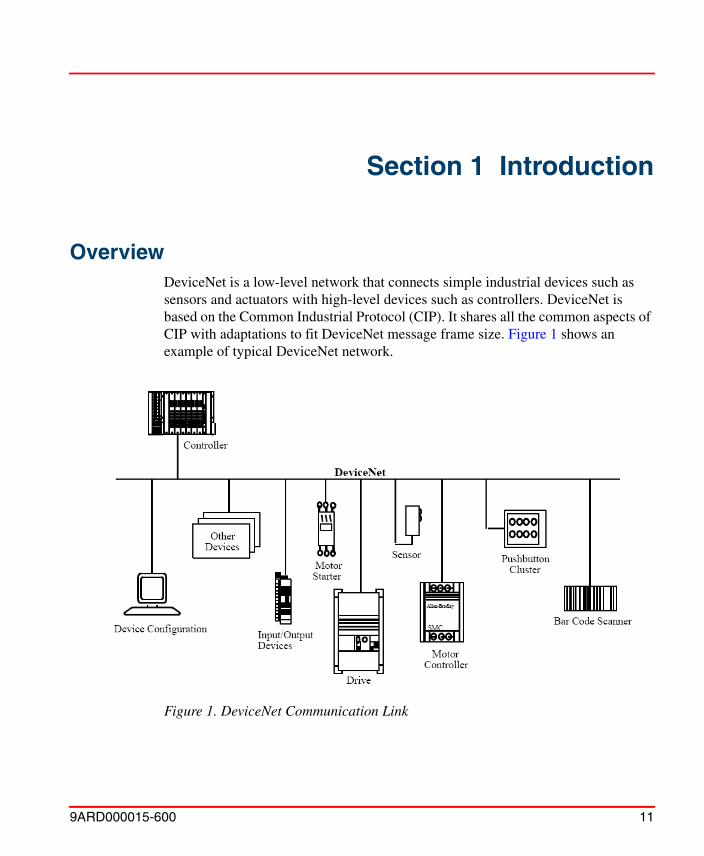
OverviewDeviceNet is a low-level network that connects simple industrial devices such as sensors and actuators with high-level devices such as controllers. DeviceNet is based on the Common Industrial Protocol (CIP). It shares all the common aspects of CIP with adaptations to fit DeviceNet message frame size. Figure 1 shows an example of typical DeviceNet network.
Figure 1. DeviceNet Communication Link

Physical Layer and Media Features Section 1 Introduction
12 9ARD000015-600
Physical Layer and Media FeaturesThe DeviceNet Physical Layer and Media includes the following features:
• Uses Controller Area Network (CAN) technology.
• Small size and low cost.
• Linear bus topology.
• Ability to operate at three data rates:
– 125 kBaud up to 500 m (1640 ft) maximum.
– 250 kBaud up to 250 m (820 ft) maximum.
– 500 kBaud up to 100 m (328 ft) maximum.
• Bus wires containing both signal and power conductors.
• Low loss, low delay cable.
• Supports various media for drop line or trunk line.
• Supports drop lines upto 6 m (20 ft).
• Supports up to 64 nodes.
• Node removal without severing the network.
• Ability to support both isolated and nonisolated Physical Layers simultaneously.
• Supports sealed media.
• Protection from wiring errors.
DeviceNet and Ethernet/IP share a common upper layer protocol called Common Industrial Protocol (CIP). ABB's implementation leverages on this commonality and allows DeviceNet devices to coexist at the controller level with EtherNet/IP. The relationship of DeviceNet Physical Layer to EtherNet/IP is shown in Figure 2.
The information in the manual is derived from the Open Device Vendor Association (ODVA) standards and recommendations. For more details, refer to web site www.odva.org.

Section 1 Introduction Physical Signaling
9ARD000015-600 13
Physical Signaling
The BOSCH CAN specification defines two complimentary logical levels: dominant and recessive. During simultaneous transmission of dominant and recessive bits, the resulting bus value will be dominant. For example, in case of a wired-AND implementation of the bus (as with DeviceNet), the dominant level would be represented by a logical 0 and the recessive level by a logical 1. Physical states, for example, electrical voltage that represent the logical levels are not given in the CAN specification. The specification used for these levels is given in the ISO 11898 standard.
For a node disconnected from the bus, the recessive (high impedance) levels for CAN_L and CAN_H are 2.5 volts (0 volts differential). The typical dominant (low
Figure 2. EtherNet/IP and DeviceNet network embedded in 800xA

Physical Layer Section 1 Introduction
14 9ARD000015-600
impedance driven) levels are 1.5 volts for CAN_L and 3.5 volts for CAN_H (2 volts differential). Figure 3 shows the CAN_H and CAN_L signal levels.
Physical Layer
The Physical Layer consists of the transceiver, connector, mis-wiring protection circuitry, regulator, and optional optical isolation. Figure 4 shows the block diagram of the Physical Layer. In this section, the transceiver, mis-wiring protection (MWP), and optional isolation are explained. For more information on connectors, refer to Connectors on page 46. For more information on regulators, refer to Power Supply on page 54.
Figure 3. CAN_H and CAN_L Signal Levels

Section 1 Introduction Physical Layer Requirements
9ARD000015-600 15
Physical Layer Requirements
Physical layer requirements describes the usage of a typical integrated transceiver in a DeviceNet product. All transceivers are not the same. Ensure that the transceiver allows the device to meet the following specification for the DeviceNet physical layer:
• General Physical Layer Requirements.
• Transmitter Requirements.
• Receiver Requirements.
Figure 4. Physical Layer Block Diagram
General Physical Layer Requirements Section 1 Introduction
16 9ARD000015-600
General Physical Layer Requirements
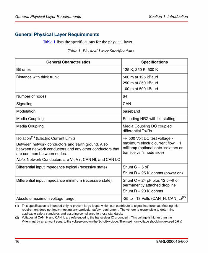
Table 1 lists the specifications for the physical layer.
Table 1. Physical Layer Specifications
General Characteristics Specifications
Bit rates 125 K, 250 K, 500 K
Distance with thick trunk 500 m at 125 kBaud
250 m at 250 kBaud
100 m at 500 kBaud
Number of nodes 64
Signaling CAN
Modulation baseband
Media Coupling Encoding NRZ with bit stuffing
Media Coupling Media Coupling DC coupled differential Tx/Rx
Isolation(1) (Electric Current Limit)
Between network conductors and earth ground. Also between network conductors and any other conductors that are common between nodes.
Note: Network Conductors are V-, V+, CAN HI, and CAN LO
(1) This specification is intended only to prevent large loops, which can contribute to signal interference. Meeting this requirement does not imply meeting any particular safety requirement. The vendor is responsible to determine applicable safety standards and assuring compliance to those standards.
+/- 500 Volt DC test voltage - maximum electric current flow = 1 milliamp (optional opto-isolators on transceiver’s node side)
Differential input impedance typical (recessive state) Shunt C = 5 pF
Shunt R = 25 Kiloohms (power on)
Differential input impedance minimum (recessive state) Shunt C = 24 pF plus 12 pF/ft of permanently attached dropline
Shunt R = 20 Kiloohms
Absolute maximum voltage range -25 to +18 Volts (CAN_H, CAN_L)(2)
(2) Voltages at CAN_H and CAN_L are referenced to the transceiver IC ground pin. This voltage is higher than theV- terminal by an amount equal to the voltage drop on the Schottky diode. The maximum voltage should not exceed 0.6 V.

Section 1 Introduction Transmitter Requirements
9ARD000015-600 17
Transmitter Requirements
Table 2 lists the specifications for the Transmitter.
Receiver Requirements
Table 3 lists the specifications for the Receiver.
Table 2. Transmitter Specifications
Transmitter Characteristics Specifications
Differential Output level (nominal) 2.0 Volts p-p
Differential Output level (minimum) (@ connector, 50 Ohms load)
1.5 Volts p-p
Minimum Recessive Bus voltage @ CAN_H and CAN_L 2.0 Volts(1)
(1) Voltages at CAN_H and CAN_L are referenced to the transceiver IC ground pin. This voltage is higher than the V- terminal by an amount equal to the voltage drop on the Schottky diode. The maximum voltage should not exceed 0.6 V.
Maximum Recessive Bus voltage @ CAN_H and CAN_L 3.0 Volts(1)
Transmitter delay 120 ns maximum opto(40)+xcvr(80)
Output short circuit protection internally limited
Table 3. Receiver Specifications
Receiver Characteristics Specifications
Differential Input Voltage Dominant 0.95 Volts minimum
Differential Input Voltage Recessive 0.45 Volts maximum
Hysteresis 150 mV typical
Receiver delay 130 ns max opto(40)+xcvr(90)
Operating voltage range -5 to +10 Volts (CAN_H, CAN_L)(1)
(1) Voltages at CAN_H and CAN_L are referenced to the transceiver IC ground pin. This voltage is higher than the V- terminal by an amount equal to the voltage drop on the Schottky diode. The maximum voltage should be 0.6 V.

Receiver Requirements Section 1 Introduction
18 9ARD000015-600

9ARD000015-600 19
Section 2 Transmission Media andComponents
TopologyThe DeviceNet media has a linear bus topology. Terminating resistors are required on each end of the trunk line. Drop lines upto 6 m (20 feet) each are permitted for attaching nodes to the DeviceNet network. Branching structures are allowed in the DeviceNet only on the drop line. For more information about the power delivery capability on the trunk line and drop line, refer to Defining Power Configuration on page 64. Figure 5 shows the DeviceNet media technology.
Figure 5. DeviceNet Media Technology

Power Supply Considerations Section 2 Transmission Media and Components
20 9ARD000015-600
The total number of trunk lines allowed on the network depends on the data rate and the type of cable used. The cable distance between any two points in the cable system must not exceed the Maximum Cable Distance allowed for the baud rate.
For information on trunk lines constructed using only one type of cable, and also to determine the Maximum Cable Distance based on the data rate and the type of cable used, refer to cable profiles under Cable Types on page 21.
The Cable distance between two points includes both trunk line cable length and drop line cable length that exists between the two points. DeviceNet allows different types of cables in a trunk system. The Details of the equivalencies when mixing different types of cables in trunk lines for the respective cable types are described in section Cable Types on page 21.
Drop line length is the longest cable distance, which is measured from the tap on the trunk line to each of the transceivers of the nodes on the drop line. This distance includes any dropline cable, which might be permanently attached to the device. The total amount of drop line allowable on the network depends upon the data rate. When determining the number and length of drop lines, refer to the cable profile under Cable Types on page 21.
Power Supply Considerations
Network Grounding
DeviceNet should be grounded in one location only. Grounding in more than one location may produce ground loops. Non grounding of the network will increase sensitivity to Electrostatic Discharge (ESD) and outside noise sources. The single grounding location should be at a power tap. Sealed DeviceNet power taps are designed to accommodate grounding. Grounding near the physical center of the network is also recommended.
The trunk drain/shield should be attached to the power supply ground or V- with a copper conductor, which is either solid, stranded, or braided. When using a flat cable, only the V- is connected to a good earth ground. Use a 1 inch copper braid (8 AWG) wire that is less than 3 meters/10 feet in length. This should then be attached to a good earth or building ground.

Section 2 Transmission Media and Components Cable Types
9ARD000015-600 21
If the network is already grounded, do not connect the grounding terminal of the tap or ground of the supply to earth. If more than one supply is on the network, then connect the drain wire/shield at one supply only, preferably near the physical center of the network.
Cable TypesThe following data consists of the specifications for different cable types:
• Data Pair Specifications.
• Power Pair Specifications.
• General Specifications.
• Topology.
• Physical Configuration.
• Available Bus Electric Current.
Grounding should always be done according to Federal, State and Local regulations.
The specification lists only 3 types of cables such as Thick cable, Thin cable, and Flat cable.

Thick Cable Section 2 Transmission Media and Components
22 9ARD000015-600
Thick Cable
Figure 6 shows the physical configuration of Thick cable.
Table 4 provides the various specifications of Thick cable and their corresponding table numbers.
Figure 6. Thick Cable Physical Configuration
Table 4. Specifications for Thick Cable and their Corresponding Table Numbers
Characteristics Table Number
Data Pair Specification
Physical Table 5
Electrical Table 6
DC Power Specification
Physical Table 7
Electrical Table 8
General Specification
Physical Table 9

Section 2 Transmission Media and Components Thick Cable
9ARD000015-600 23
Electrical Table 10
Environmental Table 11
Table 5. Physical Characteristics of Data Pair Specification for Thick Cables
Physical Characteristics Specification
Conductor pair Size #18 Copper (minimum); 19 strands minimum (individually tinned)
Insulation diameter 0.150 inches (nominal)
Colors Light Blue
White
Pair Twist/ft 3 (approximately)
Tape shield over pair 2 mil / 1 mil, Al / Mylar
Al side out w/shorting fold (pull-on applied)
Table 6. Electrical Characteristics of Data Pair Specification for Thick Cables
Electrical Characteristics Specification
Impedance 120 Ohms +/- 10% (at 1 MHz)
Propagation delay 1.36 nSec/ft (maximum)
Capacitance between conductors 12 pF/ ft at 1 kHz (nominal)
Capacitive unbalance 1200 pF/1000 ft at 1 kHz (nominal)
Table 4. Specifications for Thick Cable and their Corresponding Table Numbers (Continued)
Characteristics Table Number

Thick Cable Section 2 Transmission Media and Components
24 9ARD000015-600
DCR - @ 20° C 6.9 Ohms/1000 ft (maximum)
Attenuation 0.13 db/100 ft @ 125 kHz (maximum)
0.25 db/100 ft @ 500 kHz (maximum)
Table 7. Physical Characteristics of DC Power Specification for Thick Cables
Physical Characteristics Specification
Conductor pair Size #15 Copper (minimum); 19 strands minimum (individually tinned)
Insulation diameter 0.098 inches (nominal)
Colors Red
Black
pair/Twist/ft 3 (approximately)
Tape shield over pair 1.0 mil/ 1 mil, Al/Mylar
Al side out w/shorting fold (pull-on applied)
Table 8. Electrical Characteristic of DC Power Specification for Thick Cables
Electrical Characteristic Specification
DCR - @ 20° C (68° F) 3.6 Ohms/1000 ft (maximum)
Table 6. Electrical Characteristics of Data Pair Specification for Thick Cables (Continued)
Electrical Characteristics Specification

Section 2 Transmission Media and Components Thick Cable
9ARD000015-600 25
Table 9. General Specification for Physical Characteristics of Thick Cables
Physical Characteristics Specification
Geometry Two shielded pairs, Common axis with drain wire in center.
Overall braid shield 65% coverage. 0.12 mm (36 AWG) tinned Cu braid minimum (individually tinned)
Drain wire #18 Copper minimum; 19 Strands minimum (individually tinned)
Outside diameter 0.410 inches (minimum) to 0.490 inches (maximum)
Roundness Radius delta to be within 15% of 0.5 O.D.
Jacket marking Vendor Name & Part #, and additional markings
Table 10. General Specification for Electrical Characteristic of Thick Cables
Electrical Characteristic Specification
DCR (braid+tape+drain) 1.75 Ohms/1000 ft (nominal @ 20° C (68° F))

Thick Cable Section 2 Transmission Media and Components
26 9ARD000015-600
Table 12 lists the topology details of Thick cable.
Table 11. General Specification for Environmental Characteristics of Thick Cables
Applicable Environmental Characteristics
Specification
Agency Certifications According to Federal, State and Local regulations.
Flexure 2000 cycles at bend radius, 90 degrees, 2 lb. Pull force, 15 cycles per minute, Tic Toc or C track method.
Bend Radius 20 x diameter (installation) / 7 x diameter (fixed)
Operating ambient temperature
-20° C .. +60° C @ 8 amps; de-rate electric current linearly to zero @ 80° C.
Storage temperature -40° C .. +85° C.
Pull tension 190 lbs maximum.
Connector Compatibility Mini, Open.
Topology Compatibility Trunk, Drop.
Table 12. Thick Cable Topology
Data Rate Max
Cable DistanceTrunk
Exchange (Thick Cable)
Cumulative Drop
Maximum Drop
125 kb 500 m (1640 ft) 1.0 156 m (512 ft) 6 m (20 ft)
250 kb 250 m (820 ft) 1.0 78 m (256 ft) 6 m (20 ft)
500 kb 100 m (328 ft) 1.0 39 m (128 ft) 6 m (20 ft)

Section 2 Transmission Media and Components Thick Cable
9ARD000015-600 27
Table 13 lists the electric current capability based on the network length.
Figure 7 shows the electric current capability on the DeviceNet Power Bus.
Table 13. Electric Current Capability for Thick Cables based on Network Length
Network Length in
Meters (feet)
025
(82)50
(164)100
(328)150
(492)200
(656)250
(820)300
(984)350
(1148)400
(1312)450
(1476)500
(1640)
Maximum Electric Current (amps)
8.00 8.00 5.42 2.93 2.01 1.53 1.23 1.03 0.89 0.78 0.69 0.63
Figure 7. Electric Current Capability on DeviceNet Power Bus

Thin Cable Section 2 Transmission Media and Components
28 9ARD000015-600
The electric current is computed using the formula:
I = 4.65V / ((Cable DCR * Length of Network) + (Contact DCR * Number of Contacts)).
Where, Cable DCR = 0.00445 ohms/ft, Contact DCR = 0.001 ohms, and Number of Contacts = 128 (because each tap has two contacts in series). The Cable DCR is determined using an ambient of 80° C, and temperature coefficient of 0.00393 per ° C.
Thin Cable
Figure 8 shows the physical configuration of Thin cable.
Table 14 provides the various specifications of Thin cable and their corresponding table numbers.
Figure 8. Thin Cable Physical Configuration
Table 14. Specifications of Thin Cable and their Corresponding Table Numbers
Characteristics Table Number
Data Pair Specification
Physical Table 15

Section 2 Transmission Media and Components Thin Cable
9ARD000015-600 29
Electrical Table 16
DC Power Specification
Physical Table 17
Electrical Table 18
General Specification
Physical Table 19
Electrical Table 20
Environmental Table 21
Table 15. Physical Characteristics of Data Pair Specification for Thin Cables
Physical Characteristics Specification
Conductor pair Size #24 Copper (minimum); 19 strands minimum (individually tinned)
Insulation diameter 0.077 inches (nominal)
Colors Light Blue
White
Pair Twist/ft 5 (approximately)
Tape shield over pair 1 mil / 1 mil, Al / Mylar
Al side out w/shorting fold (pull-on applied)
Table 14. Specifications of Thin Cable and their Corresponding Table Numbers (Continued)
Characteristics Table Number

Thin Cable Section 2 Transmission Media and Components
30 9ARD000015-600
Table 16. Electrical Characteristics of Data Pair Specification for Thin Cable
Electrical Characteristics Specification
Impedance 120 Ohms +/- 10% (at 1 MHz)
Propagation delay 1.36 nSec/ft (maximum)
Capacitance between conductors 12 pF/ ft at 1 kHz (nominal)
Capacitive unbalance 1200 pF/1000 ft at 1 kHz (nominal)
DCR - @ 20° C 28 Ohms/1000 ft (maximum)
Attenuation 0.29 db/100 ft @ 125 kHz (maximum)
0.50 db/100 ft @ 500 kHz (maximum)
0.70 db/100 ft @ 1.00 MHz (maximum)
Table 17. Physical Characteristics of DC Power Specification for Thin Cables
Physical Characteristics Specification
Conductor pair Size #22 Copper (minimum); 19 strands minimum (individually tinned)
Insulation diameter 0.055 inches (nominal)
Colors Red, Black
pair/Twist/ft 5 (approximately)
Tape shield over pair 1.0 mil/ 1.0 mil, Al/Mylar
Al side out w/shorting fold (pull-on applied)
Table 18. Electrical Characteristic of DC Power Specification for Thin Cable
Electrical Characteristic Specification
DCR - @ 20° C 17.5 Ohms/1000 ft (maximum)

Section 2 Transmission Media and Components Thin Cable
9ARD000015-600 31
Table 19. Physical Characteristics of General Specification for Thin Cables
Physical Characteristics Specification
Geometry Two shielded pairs, Common axis with drain wire in center.
Overall braid shield 65% coverage. 0.12 mm (36 AWG) tinned Cu braid minimum (individually tinned)
Drain wire #22 Copper 19 Strands minimum (individually tinned)
Outside diameter 0.240 inches (minimum) to 0.280 inches (maximum)
Roundness Delta to be within 20% of 0.5 O.D.
Jacket marking Vendor Name & Part #, and additional markings
Table 20. Electrical Characteristic of General Specification for Thin Cables
Electrical Characteristic Specification
DCR (braid+tape+drain) 3.2 Ohms/1000 ft (nominal @ 20° C)
Table 21. Environmental Characteristics of General Specification for Thin Cables
Applicable Environmental Characteristics
Specification
Agency Certifications According to Federal, State and Local regulations.
Flexure 2000 cycles at bend radius, 90 degrees, 2 lb. Pull force, 15 cycles per minute, Tic Toc or C track method

Thin Cable Section 2 Transmission Media and Components
32 9ARD000015-600
Table 22 lists the topology details of Thin cable.
Bend Radius 20 x diameter (installation) / 7 x diameter (fixed)
Operating ambient temperature -20° C .. +70° C @ 1.5 amps; de-rate electric current linearly to zero @ 80° C
Storage temperature -40° C .. +85° C
Pull tension 65 lbs maximum
Connector Compatibility Mini, Micro, Open
Topology Compatibility Trunk, Drop
Table 22. Thin Cable Topology
Data Rate Max
Cable Distance
Trunk Exchange
(Thick Cable)
Cumulative Drop
Maximum Drop
125 kb 100 m (328 ft) 5.0 156 m (512 ft) 6 m (20 ft)
250 kb 100 m (328 ft) 2.5 78 m (256 ft) 6 m (20 ft)
500 kb 100 m (328 ft) 1.0 39 m (128 ft) 6 m (20 ft)
Table 21. Environmental Characteristics of General Specification for Thin Cables (Continued)
Applicable Environmental Characteristics
Specification

Section 2 Transmission Media and Components Thin Cable
9ARD000015-600 33
Table 23 lists the electric current capability based on the network length.
Figure 9 shows the electric current capability on the DeviceNet Power Bus.
Table 23. Electric Current Capability of Thin Cables based on Network Length
Network Length in
Meters (feet)
010
(33)20
(66)30
(98)40
(131)50
(164)60
(197)70
(230)80
(262)90
(295)100
(328)
Maximum Electric Current (amps)
3.00 3.00 3.00 2.06 1.57 1.26 1.06 0.91 0.80 0.71 0.64
Figure 9. Electric Current Capability on DeviceNet Power Bus
Max
imu
m C
urr
ent
Cap
abili
ty (
amp
s)
Length of Network in meters (feet)

Flat Cable Section 2 Transmission Media and Components
34 9ARD000015-600
The electric current is computed by using the formula:
I = 4.65V / ((Cable DCR * Length of Network) + (Contact DCR * Number of Contacts)).
Where Cable DCR = 0.0216 ohms/ft, Contact DCR = 0.001 ohms, and Number of Contacts = 128 (because each taps has two contacts in series). The Cable DCR is determined using an ambient of 80° C, and temperature coefficient of 0.00393 per ° C.
Flat Cable
Figure 10 shows the physical configuration of Flat cable.
Figure 10. Flat Cable Physical Configuration

Section 2 Transmission Media and Components Flat Cable
9ARD000015-600 35
Table 24 provides the various specifications of Flat cable and their corresponding table numbers.
Table 24. Specifications of Flat Cable and their Corresponding Table Numbers
Characteristics Table Number
Data Pair Specification
Physical Table 25
Electrical Table 26
DC Power Specification
Physical Table 27
Electrical Table 28
General Specification
Physical Table 29
Electrical Table 30
Environmental Table 31
Table 25. Physical Characteristics of Data Pair Specification for Flat Cables
Physical Characteristics Specification
Conductor pair Size #16 Copper (minimum); 19 strands minimum (individually tinned)
Insulation diameter 0.110 inches (nominal)
Colors Light Blue
White
Pair Twist/ft N/A
Tape shield over pair N/A

Flat Cable Section 2 Transmission Media and Components
36 9ARD000015-600
Table 26. Electrical Characteristics of Data Pair Specification for Flat Cable
Electrical Characteristics Specification
Impedance 120 ohms +/- 10% (at 500 MHz)
Propagation delay 1.60 nSec/ft (maximum)
Capacitance between conductors N/A
Capacitive unbalance 1.2 pF/ft at 500 kHz (nominal) ASTMD4566-94
DCR - @ 20° C 4.9 ohms/1000 ft (maximum)
Attenuation 0.13 db/100 ft @ 125 kHz (maximum)
0.25 db/100 ft @ 250 kHz (maximum)
0.40 db/100 ft @ 500 KHz (maximum)
Table 27. Physical Characteristics of DC Power Specification for Flat Cables
Physical Characteristics Specification
Conductor pair Size #16 Copper (minimum); 19 strands minimum (individually tinned).
Insulation diameter 0.110 inches (nominal).
Colors Red
Black
pair/Twist/ft N/A
Tape shield over pair N/A

Section 2 Transmission Media and Components Flat Cable
9ARD000015-600 37
Table 28. Electrical Characteristic of DC Power Specification for Flat Cable
Electrical Characteristic Specification
DCR - @ 20° C 4.9 ohms/1000 ft (maximum)
Table 29. Physical Characteristics and General Specification of Flat Cable
Physical Characteristics Specification
Geometry N/A
Overall braid shield N/A
Drain wire N/A
Outside diameter N/A
Roundness N/A
Jacket marking Vendor Name & Part #, and additional markings
Table 30. Electrical Characteristic of General Specification for Flat Cables
Electrical Characteristic Specification
DCR (braid+tape+drain) N/A
Table 31. Environmental Characteristics of General Specification for Flat Cables
Applicable Environmental Characteristics
Specification
Agency Certifications According to Federal, State and Local regulations.
Flexure 1.0 M cycles at bend radius, 6 ft minimum length, 15 cycles per minute, C track method

Flat Cable Section 2 Transmission Media and Components
38 9ARD000015-600
Table 32 lists the topology details of Flat cable.
Bend Radius 10 x thickness (installation and fixed)
Operating ambient temperature
-25° C .. +75° C @ 1.5 amps; de-rate electric current linearly to zero @ 80° C
Storage temperature -40° C .. +85° C
Pull tension 90 lbs maximum
Durometer 95 Shore A (maximum)
Connector Compatibility Flat
Topology Compatibility Trunk
Table 32. Flat Cable Topology
Data Rate Max
Cable Distance
Trunk Exchange
(Thick Cable)
Cumulative Drop
Maximum Drop
125 kb 420 m (1378 ft) N/A 156 m (512 ft) 6 m (20 ft)
250 kb 200 m (656 ft) N/A 78 m (256 ft) 6 m (20 ft)
500 kb 75 m (246 ft) N/A 39 m (128 ft) 6 m (20 ft)
Table 31. Environmental Characteristics of General Specification for Flat Cables (Continued)
Applicable Environmental Characteristics
Specification
Section 2 Transmission Media and Components Flat Cable
9ARD000015-600 39
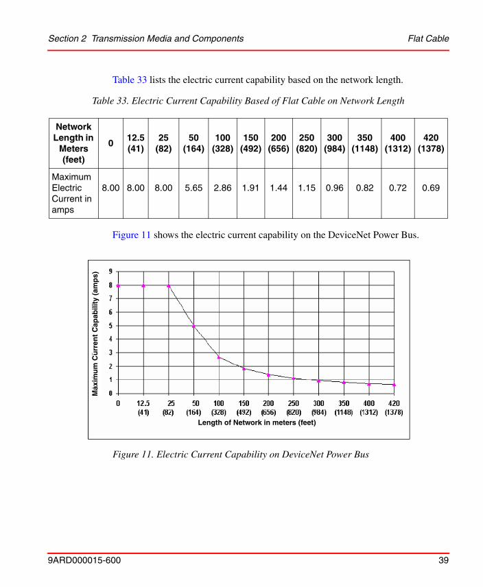
Table 33 lists the electric current capability based on the network length.
Figure 11 shows the electric current capability on the DeviceNet Power Bus.
Table 33. Electric Current Capability Based of Flat Cable on Network Length
Network Length in
Meters (feet)
012.5(41)
25(82)
50(164)
100(328)
150(492)
200(656)
250(820)
300(984)
350(1148)
400(1312)
420(1378)
Maximum Electric Current in amps
8.00 8.00 8.00 5.65 2.86 1.91 1.44 1.15 0.96 0.82 0.72 0.69
Figure 11. Electric Current Capability on DeviceNet Power Bus
Max
imu
m C
urr
ent
Cap
abili
ty (
amp
s)
Length of Network in meters (feet)

Flat Cable II Section 2 Transmission Media and Components
40 9ARD000015-600
The electric current is computed by using the formula:
I = 4.65V / ((Cable DCR * Length of Network) + (Contact DCR * Number of Contacts)).
Where Cable DCR = 0.0049 ohms/ft, Contact DCR = 0.010 ohms, and Number of Contacts = 2 (because Flat media taps installation does not put Contact DCR in series). The Cable DCR is as specified at an ambient of 20° C.
Flat Cable II
Figure 12 shows the physical configuration of Flat Cable II.
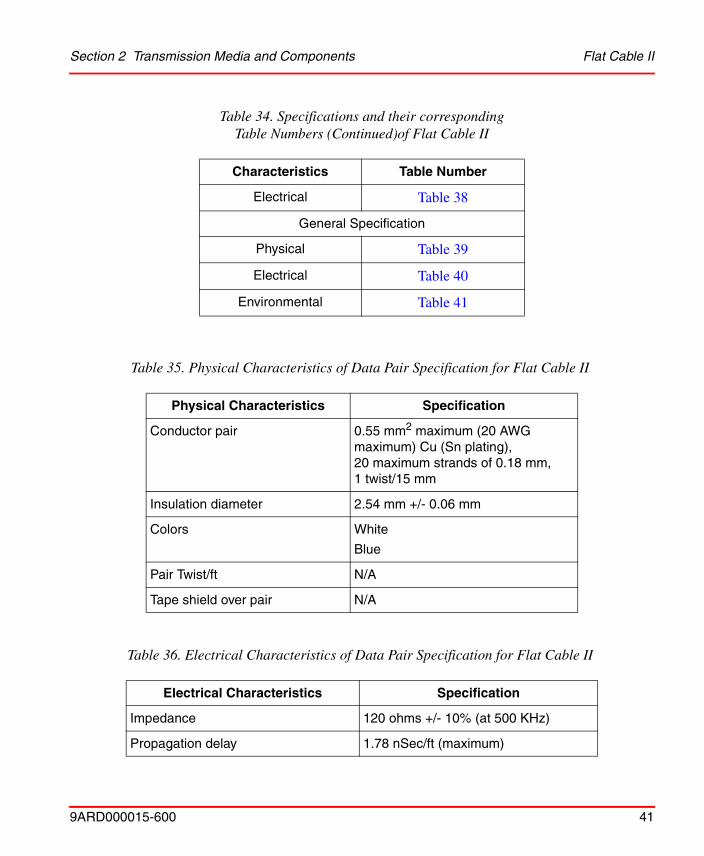
Table 34 provides the various specifications of Flat cable II and their corresponding table numbers.
Figure 12. Flat Cable II Physical Configuration
Table 34. Specifications and their correspondingTable Numbers of Flat Cable II
Characteristics Table Number
Data Pair Specification
Physical Table 35
Electrical Table 36
DC Power Specification
Physical Table 37
1: Red 2: White 3: Blue 4: Black
Section 2 Transmission Media and Components Flat Cable II
9ARD000015-600 41
Electrical Table 38
General Specification
Physical Table 39
Electrical Table 40
Environmental Table 41
Table 35. Physical Characteristics of Data Pair Specification for Flat Cable II
Physical Characteristics Specification
Conductor pair 0.55 mm2 maximum (20 AWG maximum) Cu (Sn plating), 20 maximum strands of 0.18 mm, 1 twist/15 mm
Insulation diameter 2.54 mm +/- 0.06 mm
Colors White
Blue
Pair Twist/ft N/A
Tape shield over pair N/A
Table 36. Electrical Characteristics of Data Pair Specification for Flat Cable II
Electrical Characteristics Specification
Impedance 120 ohms +/- 10% (at 500 KHz)
Propagation delay 1.78 nSec/ft (maximum)
Table 34. Specifications and their correspondingTable Numbers (Continued)of Flat Cable II
Characteristics Table Number

Flat Cable II Section 2 Transmission Media and Components
42 9ARD000015-600
Capacitance between conductors 15.8 pF/ft +5% maximum (at 1KHz, 20° C
Capacitance between one conductor and other conductor connected to shield
N/A
Capacitive unbalance 2.07 pF/ft +/- 5% ASTMD4566
DCR - @ 20° C 10.6 ohms/1000 ft (maximum) UL1581
Attenuation dB/100 ft (at 20° C) 0.14 db maximum at 125 KHz
0.25 db maximum at 250 KHz
0.42 db maximum at 500 KHz
0.72 db maximum at 1.0 KHz
Table 37. Physical Characteristics of DC Power Specification for Flat Cable II
Physical Characteristics Specification
Conductor pair 0.75 mm2 maximum (18 AWG maximum); Cu (Sn plating) 30 strands maximum of 0.18 mm minimum, twist 1twist/20 mm
Insulation diameter 2.54 mm +/- 0.06 mm
Colors Red
Black
pair/Twist/ft N/A
Tape shield over pair N/A
Table 36. Electrical Characteristics of Data Pair Specification for Flat Cable II (Continued)
Electrical Characteristics Specification

Section 2 Transmission Media and Components Flat Cable II
9ARD000015-600 43
Table 38. Electrical Characteristic of DC Power Specification for Flat Cable II
Electrical Characteristic Specification
DCR - @ 20° C 6.9 ohms/1000 ft (maximum)
Table 39. Physical Characteristics of General Specification for Flat Cable II
Physical Characteristics Specification
Geometry Flat
Overall braid shield N/A
Drain wire N/A
Outside diameter Width: 10.16 mm +0 mm, -0.5 mm
Height: 2.54 mm +/- 0.06 mm
Roundness Flat
Jacket marking Vendor Name and Certification mark
Table 40. Electrical Characteristic of General Specification for Flat Cable II
Electrical Characteristic Specification
DCR (braid+tape+drain) N/A

Flat Cable II Section 2 Transmission Media and Components
44 9ARD000015-600
Table 42 lists the topology details of Flat cable II.
Table 41. Environmental Characteristics of General Specification for Flat Cable II
Applicable Environmental Characteristics
Specification
Agency Certifications (U.S. and Canada)
To meet local regulatory agencies.
Flexure Specified by vendor (under measurement)
Bend Radius Specified by vendor
Operating ambient temperature -10° C .. +55° C
Storage temperature -20° C .. +65° C
Pull tension 40 lbs maximum
Connector Compatibility FLAT II TRUNK CONNECTOR Female and male
Topology Compatibility Trunk, Branch
Table 42. Flat Cable II Topology
Data Rate Max
Cable Distance
Trunk Exchange
(Thick Cable)
Cumulative Drop
Maximum Drop
125 kb 265 m (1050 ft) N/A 135 m (511 ft) 6 m (20 ft)
250 kb 150 m (574 ft) N/A 48 m (157 ft) 6 m (20 ft)
500 kb 75m (213 ft) N/A 35 m (82 ft) 6 m (20 ft)

Section 2 Transmission Media and Components Flat Cable II
9ARD000015-600 45
Table 43 lists the electric current capability based on the network length.
Figure 13 shows the electric current capability on the DeviceNet Power Bus.
Table 43. Electric Current Capability of Flat Cable II Based on Network Length
Network Length in
Meters (feet)
020
(66)40
(131)80
(262)100
(328)140
(459)200
(656)260
(853)300
(984)320
(1050)
Maximum Electric Current (amps)
5 5 5 2.75 2.21 1.58 1.11 0.85 0.74 0.69
Figure 13. Electric Current Capability on DeviceNet Power Bus
Length of Network in meters (feet)
Max
imu
n C
urr
ent
Cap
abili
ty (
amp
s)
Network Components Section 2 Transmission Media and Components
46 9ARD000015-600
Network Components
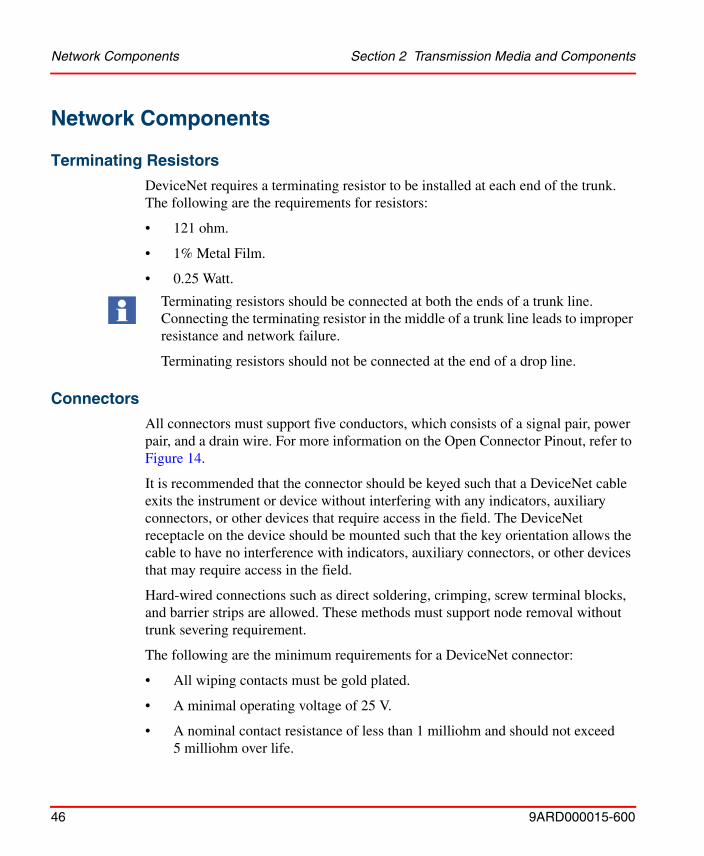
Terminating Resistors
DeviceNet requires a terminating resistor to be installed at each end of the trunk. The following are the requirements for resistors:
• 121 ohm.
• 1% Metal Film.
• 0.25 Watt.
Connectors
All connectors must support five conductors, which consists of a signal pair, power pair, and a drain wire. For more information on the Open Connector Pinout, refer to Figure 14.
It is recommended that the connector should be keyed such that a DeviceNet cable exits the instrument or device without interfering with any indicators, auxiliary connectors, or other devices that require access in the field. The DeviceNet receptacle on the device should be mounted such that the key orientation allows the cable to have no interference with indicators, auxiliary connectors, or other devices that may require access in the field.
Hard-wired connections such as direct soldering, crimping, screw terminal blocks, and barrier strips are allowed. These methods must support node removal without trunk severing requirement.
The following are the minimum requirements for a DeviceNet connector:
• All wiping contacts must be gold plated.
• A minimal operating voltage of 25 V.
• A nominal contact resistance of less than 1 milliohm and should not exceed 5 milliohm over life.
Terminating resistors should be connected at both the ends of a trunk line. Connecting the terminating resistor in the middle of a trunk line leads to improper resistance and network failure.
Terminating resistors should not be connected at the end of a drop line.

Section 2 Transmission Media and Components Connectors
9ARD000015-600 47
Figure 14 shows the pinout details of a open connector.
The nodes connecting to the DeviceNet with a connector must have male pins. This is applicable to the sealed, unsealed connectors, and all nodes that consume or supply power.
Device removal must be possible without severing or disturbing the network, regardless of the chosen connector solution.
Do not install wires while the network is active. This can effect network supply shorting or cause communication disruption.
Figure 14. Open Connector Profile
5 V+ red
4 CAN H white
3 drain bare
2 CAN L blue
1 V- black
Device Connector (Male Contacts)
Network Connector (Female Contacts)

Connectors Section 2 Transmission Media and Components
48 9ARD000015-600
Figure 15 shows the pinout details of a mini connector.
Figure 15. Mini Connector Profile
Male (pins) Female (sockets)1 - drain bare
2 - V+ red
3 - V- black
4 - CAN_H white
5 - CAN_L blue
Section 2 Transmission Media and Components Connectors
9ARD000015-600 49
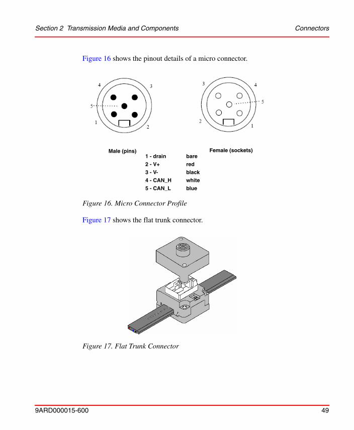
Figure 16 shows the pinout details of a micro connector.
Figure 17 shows the flat trunk connector.
Figure 16. Micro Connector Profile
Figure 17. Flat Trunk Connector
Male (pins) Female (sockets)1 - drain bare
2 - V+ red
3 - V- black
4 - CAN_H white
5 - CAN_L blue

Device Taps Section 2 Transmission Media and Components
50 9ARD000015-600
Device Taps
Device taps provide points of attachment to the trunk line. Devices can be connected to the network either directly to the tap or with a drop line. Taps also provide easy removal of a device without disrupting the network operation. Figure 18 shows the recommended keying for the Mini Trunk to Mini Drop Tap.
Power Taps
A power tap connects the power supply to the trunk line. Power taps are different from device taps and they can have the following specifications:
• A Schottky Diode, which connects to the power supply V+, allows multiple power supply connections (this eliminates the need for custom power supplies). For more information about the Schottky Diode, refer to Schottky Diode Specifications on page 57.
• Two fuses or circuit breakers to protect the bus from excess electric current, which could damage the cable and connectors.
When a power tap is connected to the network, it can provide the following:
• A continuous connection for the signal, drain, and V- wires.
• Electric current limiting in each direction from the tap.
Figure 18. Mini Trunk to Mini Drop Tap Keying
Outside threadsmale (pin) contacts
Inside threadsfemale (sockets) contacts

Section 2 Transmission Media and Components Power Taps
9ARD000015-600 51
• A connection to the shield or drain wire for grounding the network.
Power taps can be simplified for systems that use single power supply. Figure 19 shows the DeviceNet power tap components.
Table 44 lists the specifications for the Internal Pass Through Conductor.
Figure 19. DeviceNet Power Tap Components
Table 44. Internal Pass Through Conductor Specifications
Conductor Description Specification
Drain wire conductor (stranded or solid)
7 inches maximum of unshielded conductor. Maximum conductor resistance is 4 milliohm (equivalent to 7 inches of 18 AWG). Minimum conductor equivalent at any point is 18 AWG.
10 - 32 GroundingStud or grounding
Drop Connector

Power Taps Section 2 Transmission Media and Components
52 9ARD000015-600
Table 45 lists the specifications for the Internal Power Drop Conductor.
V- Power conductor (stranded or solid)
7 inches maximum conductor length. Maximum conductor resistance of 2.1 milliohms. (Equivalent to 7 inches of 15 AWG). Minimum conductor equivalent is 16 AWG.
CANH and CANL Signal conductors (stranded or solid)
7 inches maximum conductor length. Maximum resistance of 4.1 milliohms (equivalent to 7 inches of 18 AWG). Minimum conductor equivalent at any point is 22 AWG.
Table 45. Internal Power Drop Conductor Specifications
Conductor Description Specification
Drain wire conductor to grounding terminal (stranded or solid)
Maximum conductor length of 7 inches. Maximum resistance is 2.1 milliohms (equivalent to 7 inches of 15 AWG). Minimum allowable conductor at any point is 16 AWG.
V+ and V- Power conductors
(stranded or solid)
12 inches maximum conductor length per leg. Maximum resistance per leg is (excluding protection) 3.6 milliohms. (Equivalent to 12” of 15 AWG). Minimum conductor equivalent at any location is 16 AWG. Any conductor carrying between 8 and 16 amps must be 12 AWG equivalent or larger.
Table 44. Internal Pass Through Conductor Specifications
Conductor Description Specification

Section 2 Transmission Media and Components Power Taps
9ARD000015-600 53
Table 46 lists the electrical specifications of the Internal Power Drop Conductor.
Table 47 lists the environmental specifications of the Internal Power Drop Conductor.
Table 46. Electrical Specifications for Internal Power Drop Conductor
Electrical Characteristics Specification
Protection Circuit (optional) Hold, 8 amps for thick trunk, 3 amps for thin trunk.
1.5 sec minimum to 120 sec maximum trip time for 20 amps at 25° C (77° F).
Slo-Blo or Normal-Blo is allowed.
Schottky Diode (optional) 20 amp, 30 volt minimum continuous capability over environment. Maximum Vf of 0.73 volts @ Tc = 125 C and 16 A minimum test condition.
MBR3045 recommended.
Operating voltage 25 volt minimum
Contact Rating Trunk line: 8 amps minimum for thick trunk, 3 amps minimum for thin trunk, over temperature for all contacts.
Drop line: The sum of the contact ratings for both V+ and V- must be 16 amps minimum for thick drop and 6 amps minimum for thin drop over temperature.
Table 47. Environmental Specifications for Internal Power Drop Conductor
Applicable Environmental Characteristics
Specification
Water resistance (sealed) IP67 and NEMA 4, 6, 6P, 13 for sealed applications.
Oil resistance (sealed) UL-1277, OIL RES II for sealed applications.

Power Supply Section 2 Transmission Media and Components
54 9ARD000015-600
Power SupplyThe following specifications must be followed when the user designs the power supply or while establishing the power delivery aspects of the network, including the device voltage regulator:
• Power Supply Specifications.
• Network Voltage Tolerance Design Stack Up.
• Network Voltage Drop Budget.
• Schottky Diode Specifications.
• DC/DC Converter.
Power Supply Specifications
Table 48 lists the specifications for the DeviceNet power supply connection. These specifications are applicable to single supply, multiple supply, and the nodes that provide power supply to the network.
Operating ambient temperature
-40° C .. +70° C (158° F) with maximum continuous power on all conductors. De-rate linearly to 0 amps at 80° C.
Storage temperature -40° C .. +85° C
Table 48. DeviceNet Power Supply Specifications
Specification Parameter
Initial Tolerance 24 volts +/- 1% or adjustable to 0.2%
Line Regulation 0.3% maximum
Load Regulation 0.3% maximum
Table 47. Environmental Specifications for Internal Power Drop Conductor
Applicable Environmental Characteristics
Specification

Section 2 Transmission Media and Components Network Voltage Tolerance Design Stack Up
9ARD000015-600 55
Network Voltage Tolerance Design Stack Up
Table 49 outlines the stack up of tolerances leading to +/- 4% required by the DeviceNet. By using the specification provided, performance trade-offs can be made on the power supply and the Schottky diode specifications to meet the
Temperature Coefficient 0.03% per degree C maximum
Output Ripple 250 mV p-p
Load Capacitance Capability 7000 uF maximum
Temperature Range Operating(1): 0° C ... +60° C
Nonoperating: -40° C ... +85° C
Inrush Electric Current Limit Less than 65 Amps peak
Over Voltage Protection Yes (no value specified)
Over Electric Current Protection Yes (electric current limit 125% maximum)
Turn-on Time (with full load) 250 msec maximum/5% of final value
Turn-on Overshoot 0.2% maximum
Stability 0 to 100% load (all conditions)
Isolation Output isolated from AC and chassis ground.
Output Voltage 24 Volts +/- 1%
Output Electric Current Upto 16 A continuous
Surge Electric Current Capability 10% reserve capability
(1) De-rating acceptable for 60° C operation.
Table 48. DeviceNet Power Supply Specifications (Continued)
Specification Parameter

Network Voltage Drop Budget Section 2 Transmission Media and Components
56 9ARD000015-600
DeviceNet requirements. Maximum tolerance for the DeviceNet system is 24 volts +/- 4.0%.
Network Voltage Drop Budget
Table 50 lists the specifications that indicate the actual voltage levels and the maximum tolerances provided for power configuration on DeviceNet.
Table 49. Recommended Tolerance Stack Up for DeviceNet
Specification Parameter
Initial Setting 1.0%
Line Regulation 0.3%
Load Regulation 0.3%
Temperature Coefficient(1)
(1) The temperature coefficient tolerance of 0.6% is based on an actual rating of 0.03% per degree C and a 20° C differential between supplies that are used on the bus. If a supply in one location is an ambient of 40° C, then it is assumed that other supplies are within 10° C or in the range of 30 to 50° C (or another 20° C range). If this stipulation is not met and all other tolerances are met, then the power capability needs to be de-rated.
0.6%
Schottky Diode Drop (0.65 V nominal) 0.75% (of 24 volts)
Time Drift 1.05%
Total Stack Up 4.0%
Table 50. Voltage Drop Budget
Specification Tolerance Actual Voltage
Power Supply Tolerance +/-1% 0.24 V
Total Temperature Drift (1)1.8% 0.432 V
Line Regulation 0.3% 0.072 V
Load Regulation 0.3% 0.072 V

Section 2 Transmission Media and Components Schottky Diode Specifications
9ARD000015-600 57
Schottky Diode Specifications
Table 51 lists the requirement specifications for the Schottky Diode. These specifications must be followed when the diode is used in DeviceNet power supply.
DC/DC Converter
Table 52 lists the specifications for the DC/DC converter.
Diode Drop 3.04% 0.73 V
Common Mode Drop 41.66% 10.0 V
Supply Ripple 0.3125% 0.075 V
Input Ripple 3.125% 0.75 V
Total Voltage Budget 51.5% 12.96 V
(1) Based on a temperature coefficient of 0.03% and an ambient temperature of 60° C.
Table 51. Recommended Schottky Diode Specifications
Specification Parameter
Voltage Rating 30 V minimum
Electric Current Rating 25 amps
Maximum Vf @ Ifm = I0 0.73 V @Tc = 125° C with 16 A
Table 52. DC/DC Converter
Specification Parameter
Input Voltage Range 11 Volts to 25 Volts
Efficiency 70% minimum
Isolation (if required) 500 Volts
Table 50. Voltage Drop Budget
Specification Tolerance Actual Voltage

DC/DC Converter Section 2 Transmission Media and Components
58 9ARD000015-600
Turn on delay Linear Regulators none Switchers;
<100 mA 2 to 10 msec
0.1 A - 0.5 A 5 - 15 msec
0.5 A - 1 A 10 - 20 msec
1 A - 2 A 15 - 30 msec
>2 A 20 - 40 msec
Output short circuit protection
Electric Current limit
Reverse polarity protection
Schottky diode in ground path
Table 52. DC/DC Converter
Specification Parameter
9ARD000015-600 59
Section 3 Installation
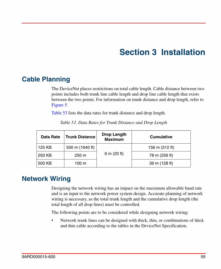
Cable PlanningThe DeviceNet places restrictions on total cable length. Cable distance between two points includes both trunk line cable length and drop line cable length that exists between the two points. For information on trunk distance and drop length, refer to Figure 5.
Table 53 lists the data rates for trunk distance and drop length.
Network WiringDesigning the network wiring has an impact on the maximum allowable baud rate and is an input to the network power system design. Accurate planning of network wiring is necessary, as the total trunk length and the cumulative drop length (the total length of all drop lines) must be controlled.
The following points are to be considered while designing network wiring:
• Network trunk lines can be designed with thick, thin, or combinations of thick and thin cable according to the tables in the DeviceNet Specification.
Table 53. Data Rates for Trunk Distance and Drop Length
Data Rate Trunk DistanceDrop Length
MaximumCumulative
125 KB 500 m (1640 ft)
6 m (20 ft)
156 m (512 ft)
250 KB 250 m 78 m (256 ft)
500 KB 100 m 39 m (128 ft)

Network Wiring Section 3 Installation
60 9ARD000015-600
• The trunk line must be terminated at each end using a terminating resistor. For more information, refer to Terminating Resistors on page 46.
• Trunk designing using thin cable has a significant impact on network power design. For more information, refer to Table 14.
Table 54 lists the data rates for trunk distance and drop length.
Calculating the total cable length
1. The distance between any two points must not exceed the maximum cable length allowed for the baud rate. Always use the longest distance between two nodes in the network. For the cable length, refer to Figure 20.
For the respective cable type topology, refer to Table 12, Table 22, Table 32, Table 42.
The cable length allowed is calculated using the following formulas:
ThickL + 5 * ThinL < 500 m for 125 kb
ThickL + 5 * ThinL < 250 m for 250 kb
ThickL + 5 * ThinL < 125 m for 500 kb
where ThickL is the length of the thick cable and ThinL is the length of the thin cable.
2. The maximum trunk line distance is measured between the two terminating resistors.
Table 54. Data Rates for Trunk Distance and Drop Length
Data Rate Trunk DistanceDrop Length
MaximumCumulative
125 KB 500 m (1640 ft)
6 m (20 ft)
156 m (512 ft)
250 KB 250 m (820 ft) 78 m (256 ft)
500 KB 125 m (410 ft) 39 m (128 ft)
Section 3 Installation Network Wiring
9ARD000015-600 61
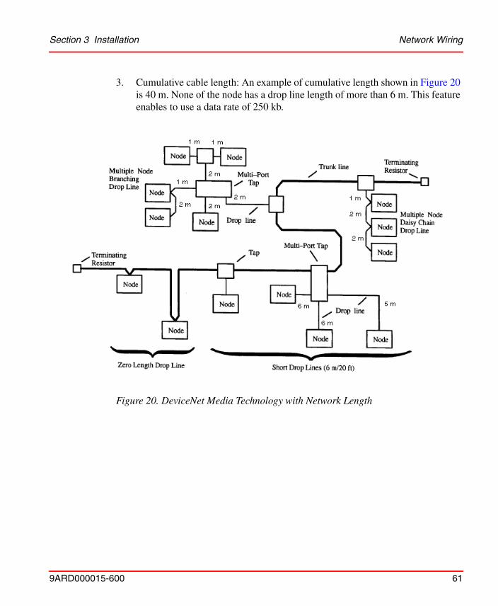
3. Cumulative cable length: An example of cumulative length shown in Figure 20 is 40 m. None of the node has a drop line length of more than 6 m. This feature enables to use a data rate of 250 kb.
Figure 20. DeviceNet Media Technology with Network Length
Cable Color Code Section 3 Installation
62 9ARD000015-600
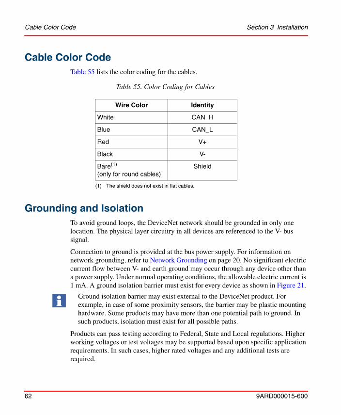
Cable Color CodeTable 55 lists the color coding for the cables.
Grounding and IsolationTo avoid ground loops, the DeviceNet network should be grounded in only one location. The physical layer circuitry in all devices are referenced to the V- bus signal.
Connection to ground is provided at the bus power supply. For information on network grounding, refer to Network Grounding on page 20. No significant electric current flow between V- and earth ground may occur through any device other than a power supply. Under normal operating conditions, the allowable electric current is 1 mA. A ground isolation barrier must exist for every device as shown in Figure 21.
Products can pass testing according to Federal, State and Local regulations. Higher working voltages or test voltages may be supported based upon specific application requirements. In such cases, higher rated voltages and any additional tests are required.
Table 55. Color Coding for Cables
Wire Color Identity
White CAN_H
Blue CAN_L
Red V+
Black V-
Bare(1) (only for round cables)
(1) The shield does not exist in flat cables.
Shield
Ground isolation barrier may exist external to the DeviceNet product. For example, in case of some proximity sensors, the barrier may be plastic mounting hardware. Some products may have more than one potential path to ground. In such products, isolation must exist for all possible paths.

Section 3 Installation Configuring Network Power
9ARD000015-600 63
Configuring Network Power
DeviceNet provides power supply in addition to providing communication. As both power and signal conductors are contained in the cable, devices can draw power directly from the network or from the DeviceNet bus. DeviceNet has a single supply electric current capability of up to 16 amps depending on the selection of cable.
The maximum electric current for cable types is listed in the appropriate cable specifications in Cable Types on page 21. Smaller gauge cables provide a cost-effective means of designing a highly functional, flexible, low electric current cable system.
The following are the power bus capabilities of DeviceNet:
• Cable length upto 500 m (1,640 ft).
• Support for as many as 64 nodes of varying electric current.
• Adjustable configuration.
The flexibility of DeviceNet provides various power design choices. This section provides guidelines for configuring power along a network, which increases performance and decreases cost.
Figure 21. DeviceNet Ground Isolation
Power Tap
Power Supply
Earth Ground

Defining Power Configuration Section 3 Installation
64 9ARD000015-600
Figure 22 shows power along the network with signal and power conductors running in cables.
Defining Power ConfigurationPower configuration can be adjusted based on the system requirements. A nominal 24 V source provides power supply to the DeviceNet power bus. It can support upto 8 amps on any section based on the trunk cable type used (refer to Cable Types on page 21 and cable technical specifications) or less electric current using small gauge cables. For examples on maximum electric current capacity for each cable type, refer to Cable Types on page 21.
As the electric current drawn from each side of a power tap is more, a single supply network can possibly provide twice the amount as drawn from a power tap. If the system requirement is more, DeviceNet can support multiple power supplies that can result in almost unlimited power. Majority of DeviceNet applications require only one power supply.
For examples of detailed specifications on the various aspects and components involved in power, refer to Power Supply on page 54. To install a specific component, refer to the specifications provided by the component supplier.
Figure 22. Power in the Network with Signal and Power Conductors in Cable
Power Conductor
Signal Conductor
Back-up SupplyPower Tap
Node Node Node Node Node Node
24 voltPowerSupply

Section 3 Installation Quick Start
9ARD000015-600 65
The trunk line can be constructed using single cable types within a segment. As defined in the individual examples of cable profiles in Cable Types on page 21, mixing of cable types in the same segment is permitted with appropriate de-rating.
The electric current availability on the network depends on the following limitations. More than one limitation can exist at the same time.
• Cable Type (electric current capacity).
• Connector Type (contact rating).
• The maximum common mode limit of the transceiver (this parameter limits the voltage drop that can be tolerated on the power cable.)
For trunk cable electric current that corresponds to the maximum common mode voltage drop, refer to Cable Types on page 21.
Quick Start
Execute the following steps to configure power:
1. Add all the electric current requirements for each device on the network.
2. Measure the total length of the network.
3. For electric current capability based on the network length and the cable type used, refer to Section Cable Types on page 21 or the catalogue of the cable supplier.
4. If the electric current accumulated from each device is less than the value given in the catalogue for the cable, then any one of the configurations available in the Primary Network Configuration on page 66 can be used.
5. If the electric current accumulated from each device is greater than the value given in the catalogue for the cable, then refer to Single supply end-connected on page 66. The section Single supply end-connected on page 66 duplicates the
Before installing the DeviceNet, the user should be familiar with the country and local codes of the location where it is to be installed. In U.S. and Canada, while installing the DeviceNet cable types in building wiring, it must be installed as a Class 2 circuit. This requires electric current limiting to 4 amps in all sections. The system components rating is 8 amps.

Primary Network Configuration Section 3 Installation
66 9ARD000015-600
calculations given in the section Primary Network Configuration on page 66 and can be skipped.
Primary Network Configuration
Based on the power requirement and cable type select one of the primary network configuration from the following:
• Single supply end-connected.
• Single supply center-connected.
Single supply end-connected
The calculations executed in Quick Start on page 65 determines if the network supports this configuration. For example, while using the Thick cable, if the accumulated electric current requirement for the network exceeds the value available in Table 13, then Single supply end-connected configuration is not appropriate for the network. Single supply end-connected is the simplest configuration but provides lowest power capability.
Figure 23 shows a power configuration for a 700 foot network with a single supply end-connected using a thick cable trunk line. The power calculation procedure is the same as described in Quick Start on page 65.
The power supply capability must be equal to or greater than the load requirement on the network.

Section 3 Installation Primary Network Configuration
9ARD000015-600 67
Calculation method:
Total network length = 700 feet
Total electric current = 0.1 A + 0.15 A + 0.05 A + 0.25 A + 0.1 A = 0.65 A
Table 13 electric current limit for 700 feet = 1.5 A
Conclusion: All configurations are acceptable for this network.
Single supply center-connected
If the Single supply end-connected calculation indicates that the power supply must not be placed at the end of the network, then use the following steps to determine the validity of the power supply connected at the physical center of the network. A single center-connected supply provides double the total of the electric current capability than the single end-connected supply.
1. Add the electric current ratings of the devices in each section (refer to Figure 24) to determine the total electric current in each section. As the supply is center-connected, the bus has two sections (one on each side of the power tap).
2. For the maximum electric current capability of thick cable trunk line in each section based on section length, including the power supply drop cable, refer to Table 13 and Figure 7.
Figure 23. Single Supply End-Connected
Power Tap
PowerSupply

Primary Network Configuration Section 3 Installation
68 9ARD000015-600
3. If thin cable trunk line is used for a section, then refer to Table 23 and Figure 9.
4. If the electric current in both thick trunk line and thin trunk line are lower than the values provided in the respective tables (Table 13 and Table 23), then the network can support a single supply center-connected configuration.
Figure 24 shows the single supply center-connected using a thick cable trunk line.
Calculation method:
Section 1 length = Section 2 length = 400 ft.
Section 1 electric current = 0.1 A + 0.25 A + 0.2 A = 0.55 A.
Section 2 electric current = 0.15 A + 0.25 A + 0.15 A = 0.55 A.
Table 13 electric current limit for 400 ft (Section 1) = 2.63 A.
Table 13 electric current limit for 400 ft (Section 2) = 2.63 A.
Conclusion: Power supply located in the center is feasible for both sections.
Figure 24. Single Supply Center-Connected
Power Tap
Power Supply
Section 3 Installation Primary Network Configuration
9ARD000015-600 69
If the electric current determined in Step 2 in a given section exceeds the maximum electric current capability according to the respective tables, then based on the circumstances, execute one of the following:
If the electric current exceeds the maximum,
a. In one of the two sections, then execute one of the following actions:
– Move the position of the supply along the overloaded section and recalculate.
– Move the power supply to push one of the nodes from the overloaded section to the other section.
b. In both sections
– use two power supplies.
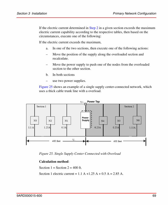
Figure 25 shows an example of a single supply center-connected network, which uses a thick cable trunk line with a overload.
Calculation method:
Section 1 = Section 2 = 400 ft.
Section 1 electric current = 1.1 A +1.25 A + 0.5 A = 2.85 A.
Figure 25. Single Supply Center Connected with Overload
Power Supply
Power Tap

Primary Network Configuration Section 3 Installation
70 9ARD000015-600
Section 2 electric current = 0.25 A + 0.25 A + 1.15 A = 1.65 A.
Table 13 electric current limit for 400 ft (Section 1) = 2.63 A.
Table 13 electric current limit for 400 ft (Section 2) = 2.63 A.
Conclusion: Section 1 is overloaded.
Solution: Move the supply in the direction of the overloaded section.
Figure 26 shows a solution to Single supply center-connected with overload.
Calculation method:
Section 1 = 300 ft.
Section 2 = 500 ft.
Section 1 electric current = 1.1 A + 1.25 A = 2.35 A.
Section 2 electric current = 0.5 A + 0.25 A + 0.25 A + 0.85 A = 1.85 A.
Table 13 electric current limit for 300 ft (Section 1)= 3.51 A.
Table 13 electric current limit for 500 ft (Section 2) = 2.10 A.
Conclusion: No overload on either of the sections. This configuration is feasible.
Figure 26. Solution to Single Supply Center-Connected with Overload
Power Tap
Power Supply

Section 3 Installation Load Limit
9ARD000015-600 71
Load Limit
For examples of maximum electric current that can flow on the network power bus for each cable type, refer to section Cable Types on page 21. The maximum drop line electric current depends on the length of the drop line.
The electric current limits for drop lines are listed in Table 56. The electric current limit is described by the following equations:
I = 15/L
where I is the allowed drop line electric current in amps and L is the drop length in feet, or:
I = 4.57/L
where I is the allowed drop line electric current in amps and L is the drop length in meters.
The operating electric current of the device represents the average electric current drawn from the bus.
If the maximum operating electric current of the device exceeds the average electric current by 10%, then the maximum operating electric current must be specified in the product data sheet.
Table 56. Maximum allowed Drop Line Electric Current
Drop Length (ft)
Maximum Allowable Electric Current (amps)
1 3.0
3 3.0
5 3.0
7.5 2.0
10 1.5
15 1.0
20 0.75

System Tolerance Section 3 Installation
72 9ARD000015-600
System Tolerance
It is possible to make performance trade-offs and meet the DeviceNet requirements by using the stack up limits listed in Table 57. The maximum system voltage tolerance for DeviceNet is 24 volts +/- 4.0%. Table 57 lists the allocated tolerance budget.
Avoiding Errors
ODVA suggests the following steps to minimize the number of design and construction errors that could be encountered while configuring power on the network:
• Execute the calculations suggested in the section Configuring Network Power on page 63 to prevent network overloading.
• To verify accurate configuration, measure the voltage once the network is constructed. A minimum of 11 volts is required at a node and the maximum voltage drop (from V+ to V-) of 10 V is permitted.
• Allow sufficient margin of error to correct configuration problems without damaging the network.
• For heavily loaded multiple supplies, turn on all supplies simultaneously to prevent overloading fuses or make sure that unpowered sections are disconnected from the rest of the network.
Table 57. Recommended Stack Up Standard for DeviceNet
Specification Parameter
Initial Power Supply Setting 1.0%
Line Regulation 0.3%
Load Regulation 0.3%
Temperature Drift 0.6% total
Schottky Diode Drop 0.75%
Time Drift 1.05%
Total Stack Up 4.0%

Section 3 Installation Power Supply Options
9ARD000015-600 73
Power Supply Options
The DeviceNet power tap protects the network from unlimited electric current flow. Any of the shelf power supply can be used until it meets the following general requirements and the detailed requirements listed in Table 48.
• +24 VDC.
• Ability to support linear and switching regulators.
• Tolerance of +24 VDC +/- 1% and electric current capability of 0-16 amps (single and multiple supply applications).
• Supply outputs must be isolated from the AC line and chassis.

Power Supply Options Section 3 Installation
74 9ARD000015-600

9ARD000015-600 75
Section 4 Troubleshooting
This section describes about the various points which needs to be considered for troubleshooting and commissioning.
The following points are to be taken care before setting up the system design for installation:
• Check number of nodes.
• Check cumulative drop length.
• Check individual drop lengths.
• Check branched drop length.
• Check total trunk length, including long drop near the ends.
• Check the termination location and measure the terminators.
• Check the power supply cable length and gauge.
• Check for one, and only one, earth ground of the V- and shield.
• Break the combination shield/V- connection to frame ground and verify >1.0 Mohm to frame ground.
• Check for one and only one V- to shield connection.
• Break the shield/V- connection at the power supply and verify >1.0 Mohm shield to V- with 24VDC off.
• Check for shorts of CAN- and/or CAN+ to shield or V- verify with an OHM meter.
• Check the length and gauge of the earth ground connection.
• Check total power load and its distribution points.

Check the Power Section 4 Troubleshooting
76 9ARD000015-600
Check the Power
• Check trunk and drop current limits.
• Check type (size and length) of cable bringing power into the trunk.
• Measure the 24V supply at the middle and ends of the network.
• Consider spot checking the power for noise with an oscilloscope.
• The 24 VDC Network Power for DeviceNet Must be for the DeviceNet network only.
Check the Wiring
• Check lead dress in junction boxes.
• Check that connectors are screwed together tightly.
• Check that glands are screwed tightly.
• Check for foreign material (electrical tape, RTV, etc.) in glands.
• Check that nodes are not touching extremely hot or cold surfaces.
• Check that cables are kept a few inches away from power wiring.
• Check that cables are not draped on electric motors, relays, contactors or solenoids.
• Check that cables are not constrained so as to place excessive tension on connectors.
• Wiggle connectors to provoke intermittent failures.
Check the Scanner Configuration
• Baud Rate.
• Node Address.
Check the Nodes
• Drop 24V supply, re-power and reset the scanner to initialize the network.
• Examine the scanner display codes to identify problem nodes.
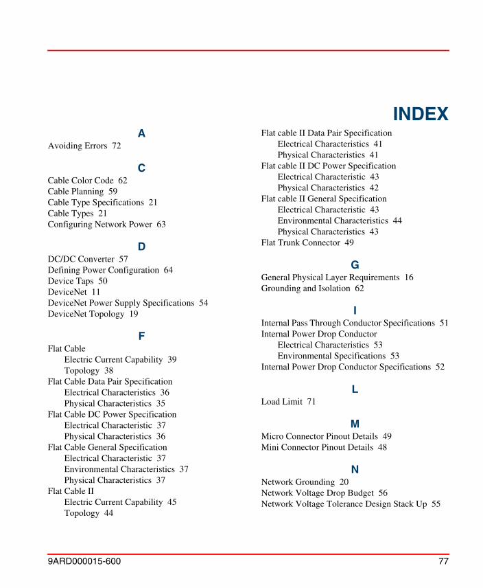
9ARD000015-600 77
AAvoiding Errors 72
CCable Color Code 62Cable Planning 59Cable Type Specifications 21Cable Types 21Configuring Network Power 63
DDC/DC Converter 57Defining Power Configuration 64Device Taps 50DeviceNet 11DeviceNet Power Supply Specifications 54DeviceNet Topology 19
FFlat Cable
Electric Current Capability 39Topology 38
Flat Cable Data Pair SpecificationElectrical Characteristics 36Physical Characteristics 35
Flat Cable DC Power SpecificationElectrical Characteristic 37Physical Characteristics 36
Flat Cable General SpecificationElectrical Characteristic 37Environmental Characteristics 37Physical Characteristics 37
Flat Cable IIElectric Current Capability 45Topology 44
Flat cable II Data Pair SpecificationElectrical Characteristics 41Physical Characteristics 41
Flat cable II DC Power SpecificationElectrical Characteristic 43Physical Characteristics 42
Flat cable II General SpecificationElectrical Characteristic 43Environmental Characteristics 44Physical Characteristics 43
Flat Trunk Connector 49
GGeneral Physical Layer Requirements 16Grounding and Isolation 62
IInternal Pass Through Conductor Specifications 51Internal Power Drop Conductor
Electrical Characteristics 53Environmental Specifications 53
Internal Power Drop Conductor Specifications 52
LLoad Limit 71
MMicro Connector Pinout Details 49Mini Connector Pinout Details 48
NNetwork Grounding 20Network Voltage Drop Budget 56Network Voltage Tolerance Design Stack Up 55
INDEX
Index
78 9ARD000015-600
Index
78 9ARD000015-600
Network Wiring 59
PPhysical Layer 14Physical Layer and Media Features 12Physical Layer Requirements 15Physical Signaling 13Power Configuration 65Power Supply Options 73Power Taps 50
RReceiver Requirements 17
SSchottky Diode Specifications 57Single supply center-connected 67Single supply end-connected 66System Tolerance 72
TTerminating Resistors 46Thick Cable
Electric Current Availability 27Topology 26
Thick Cable Data Pair SpecificationElectrical Characteristics 23Physical Characteristics 23
Thick Cable DC Power SpecificationElectrical Characteristics 24Physical Characteristics 24
Thick Cable General SpecificationElectrical Characteristic 25Environmental Characteristics 26Physical Characteristics 25
Thin CableElectric Current Capability 33Topology 32
Thin Cable Data Pair SpecificationElectrical Characteristics 30
Physical Characteristics 29Thin Cable DC Power Specification
Electrical Characteristic 30Physical Characteristics 30
Thin Cable General SpecificationElectrical Characteristic 31Environmental Characteristics 31Physical Characteristics 31
Transmitter Requirements 17


Power and productivityfor a better worldTM
Contact us
Copyright© 2003-2014 ABB.All rights reserved.
9AR
D00
0015
-600www.abb.com/800xA
www.abb.com/controlsystems