AC 150/5340-30G, Design and Installation Details for Airport Visual ...
308
Advisory Circular U.S. Department of Transportation Federal Aviation Administration Subject: Design and Installation Details for Airport Visual Aids Date: 9/21/2012 Initiated by: AAS-100 AC No.: 150/5340-30G Change: 1. PURPOSE. This advisory circular (AC) provides guidance and recommendations on the installation of airport visual aids. 2. CANCELLATION. AC 150/5340-30F, Design and Installation Details for Airport Visual Aids, dated September 29, 2011, is cancelled. 3. APPLICATION. The Federal Aviation Administration (FAA) recommends the guidance and specifications in this AC for Design and Installation Details for Airport Visual Aids. In general, use of this AC is not mandatory. However, use of this AC is mandatory for all projects funded with federal grant monies through the Airport Improvement Program (AIP) and with revenue from the Passenger Facility Charges (PFC) Program. See Grant Assurance No. 34, Policies, Standards, and Specifications, and PFC Assurance No. 9, Standards and Specifications. All lighting configurations contained in this standard are a means acceptable to the Administrator to meet the lighting requirements of Title 14 CFR Part 139, Certification of Airports, Section 139.311, Marking, Signs and Lighting. 4. PRINCIPAL CHANGES. The following changes have been incorporated: a. Paragraph 2.1.2a(2)(b)1 – added removal of filters for incandescent lamp and white/yellow fixture. b. Paragraph 2.1.2b(1)(c) is added to prevent mixing elevated and in-pavement light fixtures for runway threshold lights. c. Paragraph 2.1.2b(2) – the EXCEPTION paragraph is deleted. d. Table 2-3 – clarification for L-850D and L-850E light fixture use is added. e. Paragraph 2.1.5b adds a reference to ICAO Aerodrome Design Manual, Part 5, Electrical Systems, for the technical aspects of interleaving airport lighting circuits. f. Paragraph 3.2 is updated to include a reference to FAA Order 8900.1 for RVR takeoff minima. g. Paragraph 3.3a(3) is updated to add words “equal to or less than 700 feet” for displaced threshold and centerline lights. h. Paragraph 4.3c NOTE is corrected to 2.5 ft. (0.8 m) for displacement of taxiway centerline lights.
Transcript of AC 150/5340-30G, Design and Installation Details for Airport Visual ...

Advisory
Circular U.S. Department
of Transportation
Federal Aviation
Administration
Subject: Design and Installation Details for
Airport Visual Aids
Date: 9/21/2012
Initiated by: AAS-100
AC No.: 150/5340-30G
Change:
1. PURPOSE. This advisory circular (AC) provides guidance and recommendations on the installation
of airport visual aids.
2. CANCELLATION. AC 150/5340-30F, Design and Installation Details for Airport Visual Aids,
dated September 29, 2011, is cancelled.
3. APPLICATION. The Federal Aviation Administration (FAA) recommends the guidance and
specifications in this AC for Design and Installation Details for Airport Visual Aids. In general, use of
this AC is not mandatory. However, use of this AC is mandatory for all projects funded with federal grant
monies through the Airport Improvement Program (AIP) and with revenue from the Passenger Facility
Charges (PFC) Program. See Grant Assurance No. 34, Policies, Standards, and Specifications, and PFC
Assurance No. 9, Standards and Specifications. All lighting configurations contained in this standard are a
means acceptable to the Administrator to meet the lighting requirements of Title 14 CFR Part 139,
Certification of Airports, Section 139.311, Marking, Signs and Lighting.
4. PRINCIPAL CHANGES. The following changes have been incorporated:
a. Paragraph 2.1.2a(2)(b)1 – added removal of filters for incandescent lamp and white/yellow
fixture.
b. Paragraph 2.1.2b(1)(c) is added to prevent mixing elevated and in-pavement light fixtures for
runway threshold lights.
c. Paragraph 2.1.2b(2) – the EXCEPTION paragraph is deleted.
d. Table 2-3 – clarification for L-850D and L-850E light fixture use is added.
e. Paragraph 2.1.5b adds a reference to ICAO Aerodrome Design Manual, Part 5, Electrical
Systems, for the technical aspects of interleaving airport lighting circuits.
f. Paragraph 3.2 is updated to include a reference to FAA Order 8900.1 for RVR takeoff minima.
g. Paragraph 3.3a(3) is updated to add words “equal to or less than 700 feet” for displaced
threshold and centerline lights.
h. Paragraph 4.3c NOTE is corrected to 2.5 ft. (0.8 m) for displacement of taxiway centerline
lights.

AC 150/5340-30G 9/21/2012
ii
i. Paragraph 4.4b(1), (2), and (3) are inserted to better define the criteria for the installation of
elevated and in-pavement runway guard lights.
j. Paragraph 4.6: text is added to clarify the operation of elevated stop bar lights.
k. Paragraph 6.6c(1) is added to better define the locations for supplemental wind cones.
l. Paragraph 7.4b is added to provide correct REIL installation requirements relevant to the
runway threshold.
m. Paragraph 7.4d NOTE is added for PAPI installations on the right side of the runway.
n. Paragraph 8.1.2e is added for lightning protection.
o. Paragraph 10.2a – a note is added to the paragraph for counterpoise distance above conduit.
p. Paragraph 12.5 is updated with a reference to recently revised NFPA 780, Standard for the
Installation of Lightning Protection Systems.
q. Paragraph 12.7 is updated to include braided ground strap of equivalent current rating.
r. Paragraph 12.12 is corrected for stainless steel bolts with black oxide coating. A reference to
Engineering Brief #83 is added regarding the use of coated bolts.
s. Paragraph 13.3, NOTE is added relevant to modifications of airfield lighting standards in FAA
Order JO 7110.65T.
t. All Figures are updated to change color text to black. In addition, yellow on white background
is changed to black on white ground.
u. Figure 3 is updated to include white/yellow light fixtures.
v. Figure 50 is modified to show a combination RGL/stop bar light fixture.
w. Figure 76 is updated to eliminate dimensions for a standard illuminated wind cone assembly.
x. Figure 81 is updated to show the PAPI on the right side of the runway.
y. Figure 82 is updated to show the correct formula for a PAPI station that is displaced toward the
runway threshold.
z. Figure 108 is updated to add elevated edge reflectors and non-applicability to runway
threshold/end lights.
5. METRICS. To promote an orderly transition to metric units, this AC contains both English and
metric dimensions. The metric conversions may not be exact metric equivalents, and, until there is an
official changeover to the metric system, the English dimensions will govern.

9/21/2012 AC 150/5340-30G
iii
6. COMMENTS OR SUGGESTIONS for improvements to this AC should be sent to:
Manager, Airport Engineering Division
Federal Aviation Administration
ATTN: AAS-100
800 Independence Avenue SW
Washington, DC 20591
7. COPIES OF THIS AC. All ACs are available online at
http://www.faa.gov/regulations_policies/advisory_circulars/.
Michael J. O’Donnell
Director of Airport Safety and Standards

AC 150/5340-30G 9/21/2012
iv
Intentionally left blank.

9/21/2012 AC 150/5340-30G
v
TABLE OF CONTENTS
CHAPTER 1. INTRODUCTION. .............................................................................................................. 1 1.1. GENERAL. ................................................................................................................................... 1 1.2. SCOPE. ......................................................................................................................................... 1 1.3. SAFETY. ...................................................................................................................................... 1 1.4. MIXING OF LIGHT SOURCE TECHNOLOGIES. .................................................................... 1
CHAPTER 2. RUNWAY AND TAXIWAY EDGE LIGHTING SYSTEMS. ........................................ 3 2.1. GENERAL. ................................................................................................................................... 3
CHAPTER 3. RUNWAY CENTERLINE AND TOUCHDOWN LIGHTING SYSTEMS. ............... 15 3.1. INTRODUCTION. ..................................................................................................................... 15 3.2. SELECTION CRITERIA. .......................................................................................................... 15 3.3. CONFIGURATION. ................................................................................................................... 15 3.4. DESIGN. ..................................................................................................................................... 16 3.5. EQUIPMENT AND MATERIAL. ............................................................................................. 17
CHAPTER 4. TAXIWAY LIGHTING SYSTEMS. ............................................................................... 19 4.1. INTRODUCTION. ..................................................................................................................... 19 4.2. IMPLEMENTATION CRITERIA. ............................................................................................ 19 4.3. TAXIWAY CENTERLINE. ....................................................................................................... 20 4.4. RUNWAY GUARD LIGHTS (RGLs). ...................................................................................... 23 4.5. RUNWAY STOP BAR............................................................................................................... 25 4.6. COMBINATION IN-PAVEMENT STOP BAR AND RGLS. .................................................. 26 4.7. CLEARANCE BAR CONFIGURATION. ................................................................................. 27 4.8. DESIGN. ..................................................................................................................................... 28 4.9. EQUIPMENT AND MATERIAL. ............................................................................................. 36 4.10. INSTALLATION. ...................................................................................................................... 37
CHAPTER 5. LAND AND HOLD SHORT LIGHTING SYSTEMS. .................................................. 39 5.1. INTRODUCTION. ..................................................................................................................... 39 5.2. BACKGROUND. ....................................................................................................................... 39 5.3. DEFINITIONS. ........................................................................................................................... 39 5.4. IMPLEMENTATION CRITERIA. ............................................................................................ 39 5.5. CONFIGURATION. ................................................................................................................... 39 5.6. DESIGN. ..................................................................................................................................... 40 5.7. EQUIPMENT AND MATERIAL. ............................................................................................. 42 5.8. INSTALLATION. ...................................................................................................................... 43
CHAPTER 6. AIRFIELD MISCELLANEOUS AIDS. .......................................................................... 45 6.1. AIRPORT ROTATING BEACONS. ......................................................................................... 45 6.2. SYSTEM DESIGN. .................................................................................................................... 45 6.3. INSTALLATION. ...................................................................................................................... 46 6.4. MAINTENANCE. ...................................................................................................................... 47 6.5. BEACON TOWERS. .................................................................................................................. 47 6.6. WIND CONES. .......................................................................................................................... 48 6.7. OBSTRUCTION LIGHTS. ........................................................................................................ 49 6.8. EQUIPMENT AND MATERIALS. ........................................................................................... 51
CHAPTER 7. ECONOMY APPROACH AIDS. ..................................................................................... 53 7.1. INTRODUCTION. ..................................................................................................................... 53 7.2. TYPES OF ECONOMY APPROACH LIGHTING AIDS. ........................................................ 53 7.3. SELECTION CONSIDERATIONS. .......................................................................................... 53 7.4. CONFIGURATIONS. ................................................................................................................ 54 7.5. DESIGN. ..................................................................................................................................... 56 7.6. EQUIPMENT AND MATERIAL. ............................................................................................. 66 7.7. INSTALLATION. ...................................................................................................................... 67

AC 150/5340-30G 9/21/2012
vi
CHAPTER 8. RADIO CONTROL EQUIPMENT. ................................................................................ 71 8.1. RADIO CONTROL EQUIPMENT. ........................................................................................... 71
CHAPTER 9. STANDBY POWER – NON-FAA.................................................................................... 75 9.1. BACKGROUND. ....................................................................................................................... 75 9.2. DEFINITIONS. ........................................................................................................................... 75 9.3. FAA POLICY. ............................................................................................................................ 75 9.4. ELECTRICAL POWER CONFIGURATIONS. ........................................................................ 76 9.5. DESIGN. ..................................................................................................................................... 77 9.6. EQUIPMENT AND MATERIAL. ............................................................................................. 78 9.7. INSTALLATION. ...................................................................................................................... 80 9.8. INSPECTION. ............................................................................................................................ 81 9.9. TESTS. ........................................................................................................................................ 82 9.10. MAINTENANCE. ...................................................................................................................... 82 9.11. REDUCING ELECTRICAL POWER INTERRUPTIONS. ....................................................... 83 9.12. ENGINE GENERATOR EQUIPMENT PERFORMANCE REQUIREMENTS. ...................... 83
CHAPTER 10. PAVEMENT TYPES. ..................................................................................................... 85 10.1. GENERAL. ................................................................................................................................. 85 10.2. NEW PAVEMENT – RIGID (CONCRETE). ............................................................................ 85 10.3. NEW PAVEMENT – FLEXIBLE (BITUMINOUS). ................................................................ 87 10.4. OVERLAY – RIGID. ................................................................................................................. 88 10.5. OVERLAY - FLEXIBLE. .......................................................................................................... 89
CHAPTER 11. FIXTURE MOUNTING BASES .................................................................................... 91 11.1. GENERAL. ................................................................................................................................. 91 11.2. L-868 MOUNTING BASES. ...................................................................................................... 91 11.3. DIRECT-MOUNTED (INSET) FIXTURES. ............................................................................. 93 11.4. FIELD ADJUSTABLE L-868 MOUNTING BASES. ............................................................... 95 11.5. INSTALLATION. ...................................................................................................................... 95
CHAPTER 12. EQUIPMENT AND MATERIAL. ................................................................................. 99 12.1. GENERAL. ................................................................................................................................. 99 12.2. LIGHT BASES, TRANSFORMER HOUSINGS AND JUNCTION BOXES. .......................... 99 12.3. DUCT AND CONDUIT. ............................................................................................................ 99 12.4. CABLE, CABLE CONNECTORS, PLUGS AND RECEPTACLES. ..................................... 100 12.5. COUNTERPOISE (LIGHTNING PROTECTION SYSTEM). ................................................ 102 12.6. LIGHT BASE GROUND. ........................................................................................................ 104 12.7. LIGHT FIXTURE BONDING. ................................................................................................ 105 12.8. CONCRETE. ............................................................................................................................ 105 12.9. STEEL REINFORCEMENT. ................................................................................................... 105 12.10. ADHESIVE AND SEALANTS................................................................................................ 105 12.11. LOAD-BEARING LIGHTING FIXTURES. ........................................................................... 105 12.12. INSPECTION. .......................................................................................................................... 106 12.13. TESTING. ................................................................................................................................. 107 12.14. AUXILIARY RELAYS. ........................................................................................................... 108 12.15. VAULT. .................................................................................................................................... 108 12.16. MAINTENANCE. .................................................................................................................... 108
CHAPTER 13. POWER DISTRIBUTION AND CONTROL SYSTEMS. ........................................ 109 13.1. INTRODUCTION. ................................................................................................................... 109 13.2. POWER DISTRIBUTION. ....................................................................................................... 109 13.3. CONTROL SYSTEMS. ............................................................................................................ 110
APPENDIX 1. FIGURES. ....................................................................................................................... 115
APPENDIX 2. AIRPORT TECHNICAL ADVISORY. ....................................................................... 229
APPENDIX 3. TERMS AND ACRONYMS. ......................................................................................... 231

9/21/2012 AC 150/5340-30G
vii
APPENDIX 4. BIBLIOGRAPHY. ......................................................................................................... 237
APPENDIX 5. TYPICAL INSTALLATION DRAWINGS FOR AIRPORT LIGHTING
EQUIPMENT. ................................................................................................................ 241
APPENDIX 6. APPLICATION NOTES. .............................................................................................. 277
APPENDIX 7. RUNWAY STATUS LIGHT (RWSL) SYSTEM. ....................................................... 289
LIST OF FIGURES
Figure 1. Legend and General Notes ........................................................................................................................ 115 Figure 2. Runway and Threshold Lighting Configuration (LIRL Runways and MIRL Visual Runways) ............... 116 Figure 3. Runway and Threshold Lighting Configuration (HIRL Precision Instrument Approach - runway
centerline not shown for HIRL. Non-Precision Instrument Approach for MIRL) .............................. 117 Figure 4. Runway with Taxiway at End ................................................................................................................... 118 Figure 5. Runway with Blast Pad (No Traffic) ......................................................................................................... 119 Figure 6. Lighting for Runway with Displaced Threshold ....................................................................................... 120 Figure 7. Normal Runway with Taxiway ................................................................................................................. 121 Figure 8. Lighting for Runway with Displaced Threshold ....................................................................................... 122 Figure 9. Lighting for Runway with Displaced Threshold/Usable Pavement .......................................................... 123 Figure 10. Lighting for Runway with Displaced Threshold not Coinciding with Opposite Runway End................ 124 Figure 11. Lighting for Runway with Stopway ........................................................................................................ 125 Figure 12. Lighting for Runway with Displaced Threshold and Stopway ................................................................ 126 Figure 13. Runway with End Taxiway ..................................................................................................................... 127 Figure 14. Lighting for Runway with End Taxiway and Shortened ASDA ............................................................. 128 Figure 15. Lighting for Runway with End Taxiway and Displaced Threshold not Coinciding with Opposite
Runway End ......................................................................................................................................... 129 Figure 16. Typical Straight Taxiway Sections (Less Than 200 Ft. (61 m)) .............................................................. 130 Figure 17. Spacing of Lights on Curved Taxiway Edges ......................................................................................... 131 Figure 18. Typical Single Straight Taxiway Edges (More Than 200 Ft. (61 m)) ..................................................... 132 Figure 19. Typical Single Straight Taxiway Edges (Less Than 200 Ft. (61 m)). ..................................................... 133 Figure 20. Typical Edge Lighting Configuration ..................................................................................................... 134 Figure 21. Typical Edge Lighting for Portions of Runways Used as Taxiway (When Taxiway Lights Are
“ON”) ................................................................................................................................................... 135 Figure 22. Typical Edge Lighting for Portions of Runways Used as Taxiway (When Runway Lights Are
“ON”). .................................................................................................................................................. 136 Figure 23. Light Fixture Wiring. .............................................................................................................................. 137 Figure 24. Typical Wiring Diagram Utilizing L-828 Step-type Regulator with External Remote Primary Oil
Switch................................................................................................................................................... 138 Figure 25. Typical Wiring Diagram Utilizing L-828 Step-type Regulator with Internal Control Power and
Primary Oil Switch ............................................................................................................................... 139 Figure 26. Typical Basic 120 Volt AC Remote Control System .............................................................................. 140 Figure 27. Alternative 120 Volt AC Remote Control System .................................................................................. 141 Figure 28. Typical 120 Volt AC Remote Control System with L-847 Circuit Selector Switch ............................... 142 Figure 29. Typical 48 VDC Remote Control System with 5-Step Regulator and L-841 Relay Panel...................... 143 Figure 30. Typical 48 VDC Remote Control System with 3-Step Regulator and L-841 Relay Panel...................... 144 Figure 31. Curves for Estimating Loads in High Intensity Series Circuits ............................................................... 145 Figure 32. Curves for Estimating Loads in Medium Intensity Series Circuits ......................................................... 146 Figure 33. Runway Centerline Lighting Layout ....................................................................................................... 147 Figure 34. Touchdown Zone Lighting Layout .......................................................................................................... 148 Figure 35. Section Through Non-adjustable Base and Anchor, Base and Conduit System, Rigid Pavement .......... 149 Figure 36. Section Through Non-adjustable Base and Anchor, Base and Conduit System, Flexible Pavement ...... 150 Figure 37. Runway Centerline Light – Shallow Base and Conduit Installation ....................................................... 151 Figure 38. Saw Kerf Wireway Details ...................................................................................................................... 152 Figure 39. Saw Kerf Orientation Details – R/W Centerline and TDZ Lights ........................................................... 153

AC 150/5340-30G 9/21/2012
viii
Figure 40. Transformer Housing Installation Details Inset Type Lighting Fixtures ................................................. 154 Figure 41. Typical Equipment Layout, Inset Type Lighting Fixtures ...................................................................... 155 Figure 42. Junction Box for Inset Fixture Installation .............................................................................................. 156 Figure 43. Typical Taxiway Centerline Lighting Configuration for Non-Standard Fillets (Centerline light
spacing for operations above 1,200 ft. (365 m) RVR) ......................................................................... 157 Figure 44. Color-Coding of Exit Taxiway Centerline Lights ................................................................................... 158 Figure 45. Taxiway Centerline Lighting Configuration for Acute-Angled Exits ..................................................... 159 Figure 46. Controlled Stop Bar Design and Operation – “GO” Configuration ........................................................ 160 Figure 47. Typical Taxiway Centerline Lighting Configuration for Standard Fillets (Centerline light spacing
for operations above 1,200 ft. (365 m) RVR) ...................................................................................... 161 Figure 48. Taxiway Centerline Light Beam Orientation .......................................................................................... 162 Figure 49. In-Pavement Runway Guard Light Configuration .................................................................................. 163 Figure 50. Elevated RGL and Stop Bar Configuration ............................................................................................. 164 Figure 51. Typical Light Beam Orientation for In-Pavement RGLs and Stop Bars ................................................. 165 Figure 52. Clearance Bar Configuration at a Low Visibility Hold Point .................................................................. 166 Figure 53. Curves for Estimating Primary Load for Taxiway Centerline Lighting Systems .................................... 167 Figure 54. Typical Elevated RGL Installation Details .............................................................................................. 168 Figure 55. Typical In-Pavement RGL External Wiring Diagram – Power Line Carrier Communication, One
Light Per Remote ................................................................................................................................. 169 Figure 56. Typical In-Pavement RGL External Wiring Diagram – Power Line Carrier Communication,
Multiple Lights per Remote ................................................................................................................. 170 Figure 57. Typical In-Pavement RGL External Wiring Diagram – Dedicated Communication Link ...................... 171 Figure 58. In-Pavement RGL Alarm Signal Connection .......................................................................................... 172 Figure 59. Controlled Stop Bar Design and Operation – “STOP” Configuration .................................................... 173 Figure 60. Controlled Stop Bar Design and Operation – Intermediate Configuration .............................................. 174 Figure 61. Controlled Stop Bar Design and Operation – “STOP” Configuration for A/C 2 .................................... 175 Figure 62. Typical Layout for Land and Hold Short Lights ..................................................................................... 176 Figure 63. Typical Wireway Installation Details for Land and Hold Short Lights ................................................... 177 Figure 64. Sawing and Drilling Details for In-pavement Land and Hold Short Lights ............................................ 178 Figure 65. Typical Block Diagram for Land and Hold Short Lighting System ........................................................ 179 Figure 66. Typical Curve for Determining Maximum Separation Between Vault and Control Panel with 120
Volt AC Control ................................................................................................................................... 180 Figure 67. Beacon Dimensions and Wiring Diagram ............................................................................................... 181 Figure 68. Calculations for Determining Wire Size. ................................................................................................ 182 Figure 69. Typical Automatic Control ...................................................................................................................... 183 Figure 70. 120 Volt AC and 48 Volt DC Remote Control. ...................................................................................... 184 Figure 71. Typical Structural Beacon Tower ............................................................................................................ 185 Figure 72. Typical Tubular Steel Beacon Tower ...................................................................................................... 186 Figure 73. Typical Airport Beacon Tip-Down Pole ................................................................................................. 187 Figure 74. Typical Pre-fabricated Beacon Tower Structure ..................................................................................... 188 Figure 75. Typical Location of Supplemental Wind Cone ....................................................................................... 189 Figure 76. Externally Lighted Wind Cone Assembly (Frangible) ............................................................................ 190 Figure 77. Typical Layout for MALSF .................................................................................................................... 191 Figure 78. Typical Layout for REIL ......................................................................................................................... 192 Figure 79. Typical ODALS Layout .......................................................................................................................... 193 Figure 80. PAPI Obstacle Clearance Surface ........................................................................................................... 194 Figure 81. PAPI Signal Presentation ........................................................................................................................ 195 Figure 82. Correction for Runway Longitudinal Gradient ....................................................................................... 196 Figure 83. General Wiring Diagram for MALSF with 120 Volt AC Remote Control ............................................. 197 Figure 84. Typical Wiring Diagram for MALSF Controlled from Runway Lighting Circuit .................................. 198 Figure 85. Typical Field Wiring Circuits for MALSF .............................................................................................. 199 Figure 86. Typical Installation Details for Frangible MALS Structures – 6 foot (1.8 m) Maximum ....................... 200 Figure 87. Typical Wiring for REILs Multiple Operation ........................................................................................ 201 Figure 88. Typical Wiring for REIL Series Operation ............................................................................................. 202 Figure 89. FAA L-880 Style B (Constant Current) System Wiring Diagram ........................................................... 203 Figure 90. FAA L-880 Style A (Constant Voltage) System Wiring Diagram .......................................................... 204

9/21/2012 AC 150/5340-30G
ix
Figure 91. PAPI Light Housing Unit (LHU) Installation Detail ............................................................................... 205 Figure 92. Typical Installation Details for Runway End Identifier Lights (REILs) ................................................. 206 Figure 93. Configuration “A” Electrical Power ........................................................................................................ 207 Figure 94. Typical KVA Input Requirements........................................................................................................... 208 Figure 95. Typical Wiring Diagram for Configuration “A” Electrical Power .......................................................... 209 Figure 96. Typical Equipment Layout for Configuration “A” Electrical Power ...................................................... 210 Figure 97. Configuration “B” Electrical Power ........................................................................................................ 211 Figure 98. Typical Wiring Diagram for Configuration “B” Electrical Power .......................................................... 212 Figure 99. Typical Wiring Diagram for Configuration “C” Power .......................................................................... 213 Figure 100. Flexible Pavement or Overlay Installation ............................................................................................ 214 Figure 101. Use of Alignment Jig, No Reference Edge Available, Non-adjustable Base and Conduit System ....... 215 Figure 102. Use of Alignment Jig, Reference Edge Available, Non-adjustable Base and Conduit System ............. 216 Figure 103. In-pavement Shallow Base Runway Edge End or Threshold Light ...................................................... 217 Figure 104. In-pavement Shallow Base Runway Centerline or TDZ Light .............................................................. 218 Figure 105. Sawing and Drilling Details for In-Pavement Taxiway Centerline Lights ............................................ 219 Figure 106. Wiring Details for Direct- and Base-Mounted Taxiway Centerline Lights ........................................... 220 Figure 107. Typical Transformer Housing and Conduit Installation Details for Taxiway Centerline Lights ........... 221 Figure 108. Adjustment of Edge Light Elevation for High Snowfall Areas ............................................................. 222 Figure 109. Cable and Duct Markers ........................................................................................................................ 223 Figure 110. Counterpoise Installation ....................................................................................................................... 224 Figure 111. Power and Control System Block Diagram ........................................................................................... 225 Figure 112. Typical PLC Control System Block Diagram ....................................................................................... 226 Figure 113. PC Control System Block Diagram ....................................................................................................... 227 Figure 114. Typical Standard Details for Runway and Taxiway Edge Lights –High Intensity Light – Non-
adjustable Base-mounted...................................................................................................................... 242 Figure 115. Typical Standard Details for Runway and Taxiway Edge Lights –Medium / High Intensity Light –
Non-adjustable Base-mounted ............................................................................................................. 243 Figure 116. Typical Standard Details for Runway and Taxiway Edge Lights –Medium Intensity Light – Stake-
mounted ................................................................................................................................................ 244 Figure 117. Typical Counterpoise and Ground Rod Connections ............................................................................ 245 Figure 118. Identification (ID) Tag Detail ................................................................................................................ 246 Figure 119. Standard Details for Underground Cable Installation – Typical Multiple Bank Layout ....................... 247 Figure 120. Standard Details for Underground Cable Installation – Type A ........................................................... 248 Figure 121. Standard Details for Underground Cable Installation – Type B ............................................................ 249 Figure 122. Standard Details for Underground Cable Installation – Type C ............................................................ 250 Figure 123. Standard Details for Underground Cable Installation – Plowed Cable ................................................. 251 Figure 124. Standard Details for Underground Cable Installation – Plowed Cable ................................................. 252 Figure 125. Standard Details for Taxiway Hold and Guidance Sign – Sign – Single Pedestal ................................ 253 Figure 126. Standard Details for Taxiway Hold and Guidance Sign – Sign – Multiple Pedestal ............................. 254 Figure 127. Standard Details for Taxiway Hold and Guidance Sign – Detail A ...................................................... 255 Figure 128. Standard Details for Pivoting Rotating Beacon Pole – Rotating Beacon and Mounting Bracket
Detail .................................................................................................................................................... 256 Figure 129. Standard Details for Pivoting Rotating Beacon Pole – Locking Device Detail..................................... 257 Figure 130. Standard Details for Pivoting Rotating Beacon Pole – Pivot Detail ...................................................... 258 Figure 131. Standard Details for Pivoting Rotating Beacon Pole ............................................................................. 259 Figure 132. Standard Details for Wind Cone Foundation (L-807) ........................................................................... 260 Figure 133. Standard Details for Wind Cone – 12 ft. (3.7 m) Wind Cone ............................................................... 261 Figure 134. Standard Details for Precision Approach Path Indicators (PAPIs) – PAPI Light Unit Locations ......... 262 Figure 135. Standard Details for Precision Approach Path Indicators (PAPIs) ........................................................ 263 Figure 136. Standard Details for Precision Approach Path Indicators (PAPIs) – Section A-A ................................ 264 Figure 137. Standard Details for Runway End Identifier Light Power and Control Derived From Runway
Circuit – Profile View .......................................................................................................................... 265 Figure 138. Standard Details for Runway End Identifier Light Power and Control Derived From Runway
Circuit – Plan View .............................................................................................................................. 266 Figure 139. Location of Entrance-Exit Lights (in lieu of guidance signs) ................................................................ 267 Figure 140. Controlled Output Sign Block Diagram ................................................................................................ 277

AC 150/5340-30G 9/21/2012
x
Figure 141. Typical Power Line Carrier System ...................................................................................................... 279 Figure 142. Load Example for In Pavement RGL Circuit ........................................................................................ 284 Figure 143. ALCMS Block Diagram ........................................................................................................................ 287 Figure 144. REL Configuration for Taxiways at 90 Degrees ................................................................................... 291 Figure 145. Angled Configuration ............................................................................................................................ 292 Figure 146. Takeoff/Hold Lights .............................................................................................................................. 294 Figure 147. Runway Intersection Lights ............................................................................................................... 296
LIST OF TABLES
Table 2-1. Straight Taxiway Edge Light Spacing. ........................................................................................................ 8 Table 2-2. Edge Lighting System Design Guide. ....................................................................................................... 10 Table 2-3. Equipment and Materials. .......................................................................................................................... 13 Table 4-1. Longitudinal Dimensions. ......................................................................................................................... 21 Table 4-2. Equipment and Material Used for Low Visibility Lighting Systems. ....................................................... 37 Table 5-1. Equipment and Material Used for Land and Hold Short Lighting Systems. ............................................. 43 Table 7-1. Threshold Crossing Heights. ..................................................................................................................... 60 Table 7-2. Aiming of Type L-880 (4 Box) PAPI Relative to Pre-selected Glide Path. .............................................. 61 Table 7-3. Aiming of Type L-881 (2 Box) PAPI Relative to Pre-selected Glide Path. .............................................. 61 Table 8-1. Interface of Radio Control with Airport Visual Aids. ............................................................................... 73 Table 13-1. AGL Control System Response Times. ................................................................................................. 113

9/21/2012 AC 150/5340-30G
1
CHAPTER 1. INTRODUCTION.
1.1. GENERAL.
Numerous airport visual aids are available to provide information and guidance to pilots maneuvering on
airports. These aids may consist of single units or complex systems composed of many parts. Often
visual aids have different performance requirements and configurations, but may share common
installation procedures. For example, installation procedures for in-pavement lighting systems are
essentially the same, yet the lighting systems may perform different functions. This AC provides
installation details for all airport visual aids in one document. Performance specifications and
configuration details for the various visual aids can be found in the referenced ACs. Drawings in
Appendix 5 depict typical installation methods for various types of airport lighting equipment.
1.2. SCOPE.
This AC provides installation methods and techniques for airport visual aids. The standards contained
herein are standards the FAA requires in all applications involving airport development of this nature.
These standards must be met where lighting systems are required for FAA-developed procedures.
Installations should conform to the National Electrical Code (NEC) and local codes where applicable.
See referenced materials.
1.3. SAFETY.
Airports present a unique working environment. Airplanes traveling at high speed, multi-directional
traffic, noise, and night work are a few of the conditions that may confront a construction worker on an
airport. Safety is of paramount concern to all parties. We encourage you to become familiar with FAA
guidance contained in AC 150/5370-2, Operational Safety on Airports During Construction.
1.4. MIXING OF LIGHT SOURCE TECHNOLOGIES.
The increasing use of airport light emitting diode (LED) light fixtures on the air operations area (AOA)
has caused concerns when LED light fixtures are interspersed with their incandescent counterparts. LED
light fixtures are essentially monochromatic (aviation white excepted) and may present a difference in
perceived color and/or brightness than an equivalent incandescent fixture. These differences can
potentially distort the visual presentation to a pilot. Therefore, LED light fixtures must not be
interspersed with incandescent lights of the same type.
Example: An airport adds an extension to a runway. On the existing runway, the runway centerline light
fixtures are incandescent. The airport decides to install LED runway centerline fixtures on the new
section of runway and retains the incandescent fixtures on the existing section. This interspersion of
dissimilar technology is not approved for installation.
In addition, defective incandescent fixtures must not be replaced with their LED counterparts. When
replacing a defective light fixture, make certain that the replacement uses the same light source
technology to maintain a uniform appearance.
LED Technology System(s) that are not to be interspersed:
Runway Guard Lights – each pair of elevated RGLs must be the same technology. For in-
pavement lights, do not mix LED with incandescent fixtures in the same bar.

AC 150/5340-30G 9/21/2012
2
Touchdown Zone Lights
Runway Edge Lights including Threshold, End and Stopway
Signs per location – do not collocate LED signs with incandescent signs. Example: runway
holding position signs on both sides of a taxiway, holding position signs on both sides of a
runway, separate signs that form a sign array.
Taxiway curved segments (centerline and edge)
Taxiway Straight Segments (centerline and edge)
Approach Light Systems
Stop Bars
Runway Centerline
Rapid Exit Taxiway Indicator Lights (RETIL) (up until the holding position or runway vacated
position)
Precision Approach Path Indicator (PAPI)

9/21/2012 AC 150/5340-30G
3
CHAPTER 2. RUNWAY AND TAXIWAY EDGE LIGHTING SYSTEMS.
2.1. GENERAL.
Edge lighting systems are used to outline usable operational areas of airports during periods of darkness
and low visibility weather conditions. These systems are classified according to the intensity or
brightness produced by the lighting system.
This chapter covers standards for the design and installation of the following systems (see Figure 1 in
Appendix 1 for the legend for Figures 2 – 22):
Runway Edge Lighting Systems. Runway edge lights define the edge of the runway. The following
standard systems are described in this section:
LIRL - low intensity runway lights
MIRL - medium intensity runway lights
HIRL - high intensity runway lights
Taxiway Edge Lighting Systems. Taxiway edge lights define the edge of the taxiway. The standard
taxiway edge lighting system for airports is described in this section:
MITL - medium intensity taxiway lights
2.1.1. Selection Criteria.
The selection of a particular edge lighting system is generally based on the operational needs per the
following guidelines:
LIRL - install on visual runways (for runways at small airports),
MIRL - install on visual runways or non-precision instrument runways,
HIRL - install on precision instrument runways,
MITL - install on taxiways and aprons at airports where runway lighting systems are installed.
As stated, the above are general selection criteria. However, the airport surface requirements for specific
approach procedures are the determining factor for system selection. See AC 150/5300-13, Airport
Design, Appendix 16, for more information. Any runway edge lighting system requires that the airport be
equipped with a rotating beacon meeting the requirements of AC 150/5345-12, Specification for Airport
and Heliport Beacons.
2.1.2. Runway Edge Light Configurations.
A runway edge lighting system is a configuration of lights that defines the lateral and longitudinal limits
of the usable landing area of the runway. Two straight lines of lights installed parallel to and at equal
distances from the runway centerline define the lateral limits. The longitudinal limits of the usable
landing area are defined at each end of the area by straight lines of lights called threshold/runway end
lights, which are installed perpendicular to the lines of runway edge lights. Table 2-3, Equipment and
Materials, provides information on the recommended light fixture for each application.
a. Edge Lights.
(1) Colors.

AC 150/5340-30G 9/21/2012
4
(a) LIRL. The runway edge lights emit white light per Figure 2.
(b) MIRL and HIRL. The runway edge lights emit white light except in the caution zone
(not applicable to visual runways) which is the last 2,000 ft. (610 m) of runway or one-
half the runway length, whichever is less. In the caution zone, yellow lights are
substituted for white lights; they emit yellow light in the direction facing the instrument
approach threshold and white light in the opposite direction. Instrument approach
runways are runway end specific, meaning a runway may have an instrument approach
on one end and a non-instrument approach on the opposite end. However, when there is
an instrument approach at each runway end, yellow/white lights are installed at each
runway end in the directions described above. The yellow lights indicate caution on
rollout after landing. An example is shown in Figure 3.
(2) Location and Spacing.
(a) General. The runway edge lights are located on a line parallel to the runway centerline at
least 2 ft. (0.6 m), but not more than 10 ft. (3 m), from the edge of the full strength
pavement designated for runway use. On runways used by jet aircraft, we recommend 10
ft. (3 m) to avoid possible damage by jet blast. On runways not used by jet aircraft, we
recommend 2 ft. (0.6 m). The edge lights are uniformly spaced and symmetrical about
the runway centerline, such that a line between light units on opposite sides of the runway
is perpendicular to the runway centerline. Longitudinal spacing between light units must
not exceed 200 ft. (61 m), except as described in paragraph 2.1.2a(2)(b)1. Use the
threshold/runway end lights as the starting reference points for longitudinal spacing
calculations during design.
NOTE: See AC 150/5340-26, Maintenance of Airport Visual Aid Facilities, for
additional information about the toe-in of runway edge light fixtures. Follow the
manufacturer’s instructions for proper light fixture toe-in alignment.
(b) Intersections.
1. LIRL/MIRL. For runways with MIRL or LIRL installed and where the configuration
of the runway intersection does not allow for the matching of the runway edge lights
on opposite sides of the runway to be maintained, the distance between light units on
the same side of the runway must not exceed 400 ft. (122 m). On the side of the
runway opposite the intersection, install a single elevated runway edge light while
maintaining the designed spacing per Figure 2. For MIRL, if the distance between
the runway edge lights units is greater than 400 ft. (122 m), install an L-852D,
taxiway centerline light fixture (per AC 150/5345-46, Specification for Runway and
Taxiway Light Fixtures), modified to produce white light (by removing the filters if
an incandescent lamp is used) or white/yellow and maintain the designed spacing per
Figure 3.
2. HIRL. For runways approved for instrument landing system (ILS) CAT III
operations with HIRL installed at runway intersections, install L-850C, flush in-
pavement light fixtures (described in AC 150/5345-46, Specification for Runway and
Taxiway Light Fixtures), to maintain uniform spacing. For other operations on
runways with HIRL, the installation of a semi-flush fixture should be based on the
following:

9/21/2012 AC 150/5340-30G
5
a. The availability of other visual cues at the intersection, such as guidance signs or
centerline lighting.
b. The geometric complexity of the intersection, such as crossing runways. When
the gap exceeds 400 ft. (122 m) install an in-pavement light fixture to maintain
uniform spacing.
c. Whether the addition of a semi-flush fixture could confuse ground operations.
(c) Runway Sections Used as Taxiways. For runway or sections of runways used as
taxiways, the runway/taxiway must have the specified runway lights with the designed
spacing maintained on the dual-purpose area. It is permissible to install taxiway edge
lights on the dual-purpose area. However, taxiway centerline lighting compliant with
Chapter 4 is preferred. The control systems must be designed such that either the taxiway
lights or the runway lights are on, but both runway and taxiway lights must not be
illuminated at the same time.
NOTE: The lights on the entire runway must be off when the taxiway lights are
illuminated.
See Figure 21 and Figure 22. In some cases, where a section of the runway is used as a
taxiway, it may be desirable to install a controllable stop bar to prevent taxiing aircraft
from entering an intersecting runway. The stop bar should be interlocked with the
taxiway lights so that it is on when the taxiway lights are on.
b. Threshold/Runway End Lights.
(1) Color.
(a) Runway Thresholds. Threshold lights emit green light outward from the runway and
emit red light toward the runway to mark the ends of the runway. The green lights
indicate the landing threshold to arriving aircraft and the red lights indicate the end of the
runway for departing aircraft. The red and green lights are usually combined into one
fixture and special lenses or filters are used to emit the desired light in the appropriate
direction. The layout details for runway threshold lights are shown in Figure 2, Figure 3,
Figure 4, and Figure 5.
(b) Displaced Runway Thresholds. When the runway threshold is displaced, the lights
located in the area before the threshold emit red light toward the approach. The threshold
lights located at the displaced threshold emit green light outward from the runway
threshold. Examples of threshold lighting when the landing threshold is displaced from
the actual runway threshold are per Figure 6. Refer to AC 150/5300-13, Changes 1
through 11, Airport Design, Appendix 2 (Change 10 dated 09/29/2006), paragraph 2c,
and Appendix 14 (Change 4 dated 11/10/94), paragraph 2(c)2 for additional information
about obstructions with regard to displaced thresholds and declared distances.
(c) Light Fixtures. Light fixtures in each group on both sides of a runway threshold should
be either all elevated or all in pavement. Mixing of elevated and in-pavement light
fixtures in the same group will result in inconsistent light output.

AC 150/5340-30G 9/21/2012
6
(2) Location and Spacing.
(a) General. The combination threshold and runway end lights are located on a line
perpendicular to the extended runway centerline not less than 2 ft. (0.6 m) and not more
than 10 ft. (3 m) outboard from the designated runway threshold. The lights are installed
in two groups located symmetrically about the extended runway centerline. The
outermost light in each group is located in line with the runway edge lights. The other
lights in each group are located on 10 ft. (3 m) centers toward the extended runway
centerline. Coordinate locations and spacing of threshold/runway end lights with other
plans for future lighting equipment. Approach lighting systems are equipped with
threshold lighting located 2 ft. (0.6 m) to 10 ft. (3 m) from the threshold. If other airport
navigational equipment that is installed at the threshold prevents the lights from being
properly spaced, each light in a group may be offset not more than 1 ft. (0.3 m) in the
same direction.
1. Runways with LIRL/MIRL. Threshold/runway end lights installed on visual
runways with LIRL or MIRL must have 3 lights in each group per Figure 2.
2. Runways with MIRL/HIRL. Threshold/runway end lights installed on non-precision
instrument runways with MIRLs and precision instrument runways with HIRLs must
have 4 lights in each light group per Figure 3.
(b) Displaced Threshold. When the threshold is displaced from the end of the runway or
paved area, and access by aircraft prior to the threshold is allowed, the threshold lights
are located outboard from the runway per Figure 6. The innermost light of each group is
located in line with the line of runway edge lights, and the remaining lights are located
outward, away from the runway, on 10 ft. (3 m) centers on a line perpendicular to the
runway centerline. When the displaced runway area is usable for takeoff, red runway
edge lights are installed to delineate the outline of this area, per Figure 6.
(c) Runways Where Declared Distances are Adjusted. Airport designs for constrained
airports may require implementation of runway declared distance concepts to meet
runway safety area (RSA), runway object free area (ROFA) or the runway protection
zone (RPZ) standards in AC 150/5300-13, Airport Design. The criteria for selecting the
applicable configuration are described in AC 150/5300-13. The marking for declared
distance runways must comply with the specification described in AC 150/5340-1,
Standards for Airport Markings, and signing must comply with the standards in AC
150/5340-18, Standards for Airport Sign Systems. For configurations not covered by this
AC contact the FAA Airports Regional Office for guidance. Guidance for Declared
Distances is provided in Appendix 1 of this AC in Figures 7 thru 15.
2.1.3. Stopway Edge Lights
Definition of a stopway: A stopway is an area beyond the takeoff runway, centered on the extended
runway centerline, and designated by the airport owner for use in decelerating an airplane during an
aborted takeoff. It must be at least as wide as the runway and able to support an airplane during an
aborted takeoff without causing structural damage to the airplane. See Figure 11 and Figure 12 for
illustrations of stopways.
a. Color. The stopway edge lights emit unidirectional red light in the takeoff direction of the
runway.

9/21/2012 AC 150/5340-30G
7
b. Location and Spacing. Stopway lights are placed along its full length in two parallel rows
that are equidistant from the runway centerline and coincident with the rows of runway edge
lights. The spacing between the lights and distance from the edge is the same as runway edge
lights per paragraph 2.1.2. Lights must also be placed at the end of the stopway (spaced
symmetrically in relation to the extended runway centerline) and no more than 10 ft. (3 m)
outboard of the stopway edge per Figure 11 and Figure 12. For visual runways with
LIRL/MIRL, use two groups of three lights. For non-precision and precision instrumented
runways use two groups of 4 lights.
2.1.4. Taxiway Edge Light Configurations.
Taxiway edge lighting systems are configurations of lights that define the lateral limits of the taxiway.
a. Color. The taxiway edge lights emit blue light, and edge reflectors reflect blue.
b. Location and Spacing. Fixtures in the edge lighting system are located in a line parallel to the
taxiway centerline not more than 10 ft. (3 m) outward from the edge of the full strength
pavement. See Figure 108 for additional details about light fixture height versus lateral location
requirements in areas with high snowfall. Reflectors may be installed per paragraph 2.1.4.c of
this section in lieu of, or to enhance taxiway edge lights. The spacing for taxiway edge lights is
calculated based on the taxiway configuration. The methods of calculating taxiway edge light
spacing are described below:
NOTE: The use of in-pavement taxiway edge lighting fixtures should be restricted to where
elevated lights may be damaged by jet blast or where they interfere with aircraft operations.
(1) Straight Sections. The edge lights are spaced symmetrically using the criteria outlined in
Table 2-1, Straight Taxiway Edge Light Spacing. Lights installed on opposite sides of a
straight taxiway are aligned such that opposing lights are in a line perpendicular with the
taxiway centerline. Examples of taxiway lighting for straight taxiway sections are shown in
Figure 16, Figure 18, and Figure 19.

AC 150/5340-30G 9/21/2012
8
Table 2-1. Straight Taxiway Edge Light Spacing.
Section Length (L)
Number,
Edge Lights (N)
(per side)1
Maximum Spacing (Max)
Spacing (S)
L 50 ft. (15 m) 2
50 ft. (15 m) L
L > 50 ft. (15 m) and L
100 ft. (30 m)
3
50 ft. (15 m) L/2
L > 100 ft. (30 m) and L
200 ft. (61 m)
3
[(L/max) + 1]2 ,3
100 ft. (30 m)
50 ft. (15 m) (single edges) 3
L/2
L/(N-1) 3
L > 200 ft. (61 m) [(L/max) + 1]2
100 ft. (30 m) (single
edges) 3
200 ft. (61 m)
L/(N-1)
1 Number (N) excludes lights required for end and entrance/exit indicators.
2 Round value up to the next whole number, i.e. 1.31 becomes 2.
3 Applies to single straight taxiway only, where only one side exists. See Figure 18 and Figure 19.
(2) Curved Sections. Curved taxiway edges require shorter spacing of edge lights. The spacing
is determined based on the radius of the curve. The applicable spacing for curves is per
Figure 17. The taxiway edge lights are uniformly spaced. Curved edges of more than 30
degrees from point of tangency (PT) of the taxiway section to PT of the intersecting surface
must have at least three edge lights. For radii not listed in Figure 17 determine spacing by
linear interpolation. Taxiway spacing on curved sections at other than 14 CFR Part 139,
Certification of Airports, certificated airports may be reduced per Figure 17. In such cases,
like curves on an airport will have the same spacing.
(3) Intersections. Install end indicators on straight taxiway sections 200 ft. (61 m) or longer.
End indicators are additional taxiway edge lights installed before the intersection spaced 50
ft. (15 m) from the last light on straight taxiway sections. These lights are installed on
sections of taxiways that are more than 200 ft. (61 m) long, where edge light spacing exceeds
60 ft. (18 m). Figure 18 and Figure 19 show typical placement of end indicators.
(4) Runway-Taxiway Intersections. Taxiway guidance signs are installed at runway-taxiway
intersections to define the throat or entrance into the intersecting taxiing route. Where
taxiway signs would interfere with aircraft operations, or at small general aviation (GA)
airports, dual taxiway lights spaced per Appendix 5, Figure 139, may be installed instead of
the sign. The taxiway lights used are L-861T fixtures. Taxiway lights used per the above
must be illuminated when the runway edge lights are on.
c. Use of Reflectors. Reflectors are permitted to enhance taxiway lighting systems installed on
short taxiway sections, curves and intersections (see Figure 16 and Figure 17). In such cases,
lights are installed to meet the spacing requirements and reflectors are installed uniformly
between the lights. Reflectors are also permitted in lieu of edge lights where a centerline system
is installed. In such cases, reflectors must be installed using the required spacing for taxiway
edge lights as specified in this AC. See AC 120-57A, Surface Movement Guidance and Control
System, for additional guidance about the use of retroreflective markers. Appendix 1, Figure 108
(shows elevated light height versus the distance from the defined pavement edge) must also apply
to the use of Type II retroreflective markers in areas with high snowfall. Retroreflective markers

9/21/2012 AC 150/5340-30G
9
are described in AC 150/5345-39, FAA Specification L-853, Runway and Taxiway
Retroreflective Markers.
2.1.5. System Design.
Coordinate the lighting system design with the existing and future airport plans. Airport drawings will
show existing system(s) layout and available utilities. Install the conduits and ducts needed for the
lighting system prior to paving operations to eliminate the expense of installing these utilities in existing
pavement. Airport drainage systems may influence the location of cable ducts and trenches. Develop
design drawings showing the dimensional layout of the lighting system prior to construction. Examples
of system layouts are per Figure 20, Figure 21, and Figure 22, for high-density traffic airports.
a. Lighting Fixtures. The lighting fixtures installed in the edge lighting systems are either base-
mounted or stake-mounted. Base mounts are used for either elevated fixtures or in-pavement
fixtures. In-pavement fixtures are not permitted for the full length of the runway. They are
typically used in areas where aircraft may roll over the fixture and require load-bearing bases.
Stake mounting is typically less expensive than base mounting; however, base mounting provides
additional protection for this equipment and makes the equipment more accessible for
maintenance. Stake mounting requires the transformers, cables and connectors be buried in the
earth. A typical drawing of fixture mountings is per Figure 23. Base-mounted fixtures must be
installed using series circuits only and are recommended for HIRL, MIRL, or MITL. Stake-
mounted fixtures can be installed with either series or parallel circuits.
b. Electrical Power (Series vs. Parallel Circuits). Series powered circuits with isolation
transformers are recommended for the HIRL, MIRL, and MITL lighting systems. The
advantages of the series circuits are: 1) uniform lamp brightness, 2) lower installation cost for
long runways, generally over 4,000 ft. long, 3) reduced cold-start burnouts and in-rush currents
on turn-on, and 4) unintentional grounding will not shut the system down. Parallel power circuits
are recommended for LIRL, but may also be used for MIRL or MITL. Parallel circuits have a
lower installation cost for short runways, 4,000 ft. or less. Parallel circuits should be designed
using a 120/240 volt AC, single-phase, 3-wire system with a shared neutral. Interleave the
circuits so that each adjacent fixture is on a separate leg. Series circuits may also be interleaved,
considering requirements for equipment such as regulators and adjacent lamp monitoring during
design of the system. If two or more circuits are used to power the edge lights for one runway
and loss of power to any of those circuits will leave more than 400 ft. of the runway without edge
lights, the circuits should be coupled such that if one is energized both are energized, or if one is
de-energized both are de-energized. For additional technical information about airport lighting
circuit interleaving, see International Civil Aviation Organization (ICAO), Aerodrome Design
Manual, Document 9157-AN/901, Part 5, Electrical Systems.
c. Power Source and Monitoring. Series powered airport lighting circuits are powered by constant
current regulators (CCRs). The regulators and the associated monitoring system are described in
AC 150/5345-10, Specification for Constant Current Regulators and Regulator Monitors. The
CCRs are designed to provide the desired number of brightness steps. Some regulators,
particularly Silicon Controlled Rectifier (SCR) designs, emit electromagnetic interference (EMI)
that may degrade the performance of other air navigational equipment, such as computers, radars,
instrument landing systems, radio receivers, very high frequency omnidirectional radio ranges,
etc. See Appendix 2 for more information. Runway edge lighting systems that support CAT II or
CAT III operations should be remotely monitored and must provide the monitoring information
to the Airport Traffic Control Tower (ATCT). The monitoring systems must be capable of
detecting if more than 10 percent of the lights are inoperative. See AC 150/5340-26,

AC 150/5340-30G 9/21/2012
10
Maintenance of Airport Visual Aid Facilities, Appendix A, Standards and Tolerances, for airport
lighting operational tolerances.
Table 2-2. Edge Lighting System Design Guide.
Lighting
System
Installation Fixture Power
System
Number
of Steps
Associated Threshold
Type Mounting Design Fixtures
RUNWAY EDGE LIGHTING
HIRL
Inset 1 Base L-850C
Series 5 8 lights L-862E Elevated Base or
Stake
L-862
MIRL
Inset 1 Base L-852D Series
3 6 or 8
lights
L-861SE2
L-861E2
Elevated Base or
Stake
L-861
Series or
Parallel
LIRL Elevated Base or
Stake L-860
Series or
Parallel 1 6 lights L-860E
TAXIWAY EDGE LIGHTING
MITL
Inset Base L-852T Series 3
Elevated Base or
Stake
L-861T Series or
Parallel
3
1 Inset fixtures are not permitted for the full length of the runway. They are typically installed in areas
where aircraft may roll over the fixture. 2 For runways with either a Precision Approach Path Indicator (PAPI), runway end identifier
lights (REIL), medium approach light system (MALS), or lead-in lighting system (LDIN),
L-861E light fixture may be installed in lieu of the L-861SE. An L-861SE light fixture
should be used for MIRL if there is no PAPI, REIL, MALS, or LDIN present.
d. Brightness Steps. The brightness of the lamps is specified in steps that are defined as a
percentage of the full brightness of the lamp. (AC 150/5345-46 contains the specifications for the
light fixtures.) The following tables specify the appropriate lamp current or voltage to achieve
each brightness step:
(1) High Intensity Systems. The HIRL have five brightness steps as follows:
Percent
Brightness
Lamp
Current Step 5 100 6.6 A
Step 4 25 5.2 A
Step 3 5 4.1 A
Step 2 1.2 3.4 A
Step 1 0.15 2.8 A
(2) Medium Intensity Systems. The MIRL and MITL, when installed using a series circuit and
powered by an L-828 or L-829 regulator, have three brightness steps as follows:
Percent Lamp Current
Brightness Series Parallel Step 3 100 6.6 A 120 V
Step 2 30 5.5 A 85 V
Step 1 10 4.8 A 60 V

9/21/2012 AC 150/5340-30G
11
When MITL are installed using a parallel circuit, only one brightness step is required,
although it may be desirable to provide equivalent brightness steps as obtained with the series
circuit. This may be accomplished by use of a variable transformer, autotransformer, or other
means.
(3) Low Intensity Systems. The LIRL have only one brightness step, 100%.
e. Control Methods. The edge lighting systems should have provisions for local and/or remote
control methods. Remote controls are recommended for locations served by an air traffic control
tower, flight service station, or other manned offices where the system(s) operates. Refer to
Chapter 13 for additional information about control systems.
(1) Local Control. Local controls may be designed using direct switching at the site or automatic
controls such as a photoelectric control device or timer switch with provisions for switching
from automatic to manual control.
(2) Remote Control. Remote controls may be designed using a fixed-wire method or radio
control with L-854 equipment per AC 150/5345-49, Specification L-854, Radio Control
Equipment. Figure 24, Figure 25, Figure 26, Figure 27, Figure 28, Figure 29, and Figure 30
show some typical applications for remote controls.
(a) 120 Volts AC. Where the distance between the remote control panel and the vault is not
great enough to cause an excessive voltage drop (5%) in the control leads, the standard
control panel switches should be used to operate the control relays directly. Control
relays supplying power to the regulators must have coils rated for the control voltage.
Conductor size of the control cable should be of a size that will not cause more than a 5%
voltage drop. The voltage rating of the conductor insulation must be rated for the system
voltage. Refer to Chapter 13 for additional guidance.
(b) 120 Volts AC – Auxiliary Relay. Special low-burden pilot auxiliary relays, having
proper coil resistance to reduce control current, may be used to obtain additional
separation distance with 120 volt AC control circuits. It may be advantageous to use
these relays to expand existing 120 volt AC control circuits.
(c) 48 Volts DC. Where the distance between control panel and the vault would cause an
excessive voltage drop, a low voltage (48 volt DC) control system should be used. In
such a system, remote control panel switches activate sensitive pilot relays, such as those
specified in AC 150/5345-13, Specification for L-841 Auxiliary Relay Cabinet Assembly
for Pilot Control of Airport Lighting Circuits, which, in turn, control the regulator relays.
Use an appropriately sized cable, of a type listed for use as direct earth burial, to connect
the control panel to the pilot relays. The DC control system is adequate for up to 7,900
ft. (2408 m) separation between control point and vault. For typical application details,
see Figure 29, Figure 30 and AC 150/5345-3, Specification for L-821 Panels for Control
of Airport Lighting.
f. Runway Visual Range (RVR) Connections. Where RVR equipment is to be installed, provide
two No. 12 AWG wires for 120 volt AC control, or two No. 19 wires if 48-volt control is used,
between the control tower and the vault. The wires in the vault connect to an interface unit
provided with the RVR equipment. The wires in the tower connect to RVR equipment. All RVR
connections must be per instructions provided with the RVR system and made by personnel
responsible for the RVR or their designee.

AC 150/5340-30G 9/21/2012
12
2.1.6. Equipment and Materials.
Equipment and material covered by FAA ACs are referred to by item numbers and the associated AC
numbers where the equipment is specified - all pertinent ACs and specifications are referenced by number
and title in Appendix 4. Equipment not covered by FAA specifications, such as distribution transformers,
circuit breakers, cutouts, relays, and other commercial items of electrical equipment, must conform to the
applicable rulings and standards of the electrical industry and local code regulations. Electrical
equipment must be tested and certified by an Occupational Safety and Health Administration (OSHA)
recognized Nationally Recognized Testing Laboratory (NRTL) and should bear that mark. A current list
of NRTLs can be obtained by contacting the OSHA NRTL Program Coordinator. Table 2-3 contains a
list of equipment and material used for runway and taxiway edge lighting systems described in this
section. See Chapter 12 for additional information.
a. Light Bases, Transformer Housings and Junction Boxes. See paragraph 12.2.
b. Duct and Conduit. See paragraph 12.3.
c. Cable, Cable Connectors, Plugs and Receptacles. See paragraph 12.4.
d. Counterpoise (Lightning Protection). See paragraph 12.5.
e. Light Base Ground. See paragraph 12.6.
f. Light Fixture Bonding. See paragraph 12.7.
g. Concrete. See paragraph 12.8.
h. Steel Reinforcement. See paragraph 12.9.
i. Adhesive and Sealants. See paragraph 12.10.
j. Load-bearing Lighting Fixtures. See paragraph 12.11
k. Inspection. See paragraph 12.12.
l. Testing. See paragraph 12.13.
m. Auxiliary Relays. See paragraph 12.14.
n. Vault. See paragraph 12.15.
o. Maintenance. See paragraph 12.16.

9/21/2012 AC 150/5340-30G
13
Table 2-3. Equipment and Materials.
Item Description Item No. ACs
or Specifications
Auxiliary Relay Cabinet L-841 AC 150/5345-13
Cable L-824 AC 150/5345-7
Cable Connectors L-823 series circuits
L-108 parallel circuits
AC 150/5345-26
AC 150/5370-10
Circuit Selector Switch L-847 AC 150/5345-5
Control Panel L-821 AC 150/5345-3
Elevated Edge Light Fixture (HIRL) L-862, L-850C1 AC 150/5345-46
Elevated Edge Light Fixture (LIRL) L-860 AC 150/5345-46
Elevated Edge Light Fixture (MIRL) L-861 AC 150/5345-46
Elevated Threshold Light Fixture (HIRL) L-862 AC 150/5345-46
Elevated Threshold Light Fixture (MIRL) L-861 SE, L861E 2 AC 150/5345-46
In-pavement Light Fixture L-852 AC 150/5345-46
In-pavement Light Fixture L-850 D, E AC 150/5345-46
Isolation Transformers L-830 AC 150/5345-47
Junction Box4
L-867/L-868, blank
covers
AC 150/5345-42
Light Base and Transformer Housing 3 L-867, L-868 AC 150/5345-42
Regulators L-828, L-829 AC 150/5345-10
Retroreflective Markers L-853 AC 150/5345-39
Duct and Conduit L-110 AC 150/5370-10
Concrete P-610 AC 150/5370-10
Tape L-108 AC 150/5370-10
Vaults L-109 AC 150/5370-10
1 Install the L-850 C light fixture if in-pavement fixtures are applicable, per paragraph
2.1.2. 2 For runways with either a Precision Approach Path Indicator (PAPI), runway end
identifier lights (REIL), medium approach light system (MALS), or lead-in lighting
system (LDIN), L-861E light fixture may be installed in lieu of the L-861SE. 3 Elevated lights are installed with a 12 inch (size B) Type L-867 base or are stake-
mounted, and in-pavement light fixtures are installed with a 15 inch (size C) base or a 12
inch (size B) L-868 base. 4 Use an L-867 light base with blanking cover for a junction box or transformer housing
that must withstand occasional light vehicular loads. Use an L-868 light base with
blanking cover for a junction box or transformer housing that must withstand heavy
loads from vehicles or aircraft.

AC 150/5340-30G 9/21/2012
14
Intentionally left blank.

9/21/2012 AC 150/5340-30G
15
CHAPTER 3. RUNWAY CENTERLINE AND TOUCHDOWN LIGHTING SYSTEMS.
3.1. INTRODUCTION.
Runway centerline and touchdown zone lighting systems are designed to facilitate landings, rollouts, and
takeoffs. The touchdown zone lights are primarily a landing aid while the centerline lights are used for
both landing and takeoff operations.
3.2. SELECTION CRITERIA.
Runway centerline lights and touchdown zone lights are required for CAT II and CAT III runways and
for CAT I runways used for landing operations below 2,400 ft. (750 m) RVR. Runway centerline lights
are required on runways used for takeoff operations below 1,600 ft. (480 m) RVR unless specifically
approved by the FAA in an airline operator’s specification for that runway. See guidance in FAA Order
8900.1, Flight Standards Information Management Systems (FSIMS), Volume 4, Chapter 2, Section 9,
“Lower than Standard Takeoff Minima”, http://fsims.faa.gov/PICResults.aspx?mode=EBookContents.
Although not operationally required, runway centerline lights are recommended for CAT I runways
greater than 170 ft. (50 m) in width or when used by aircraft with approach speeds over 140 knots.
3.3. CONFIGURATION.
a. Runway Centerline Lighting.
(1) Location. The runway centerline lights are located along the runway centerline at 50 ft. (15
m) equally spaced longitudinal intervals. The longitudinal tolerance for runway centerline
lights is ± 2 ft. (0.6 meter). See Figure 33 for a graphic of the runway centerline lighting
layout. The line of runway centerline lights may be uniformly offset laterally to the same
side of the physical runway centerline a maximum of 2.5 ft. (0.8 m) (tolerance ± 1 inch (25.4
mm) measured from the physical runway centerline to the fixture centerline. For any new
runway, the light base installation must be no closer than 2 ft. (0.6 m) (measured to the edge
of the fixture base) to any pavement joints. Runway extensions of existing runways must use
the convention already established for that runway. See Paragraph 4.3 and Figure 45 for
additional information about the taxiway centerline lighting location requirements related to
runway centerline lights for major taxiway turnoffs. See AC 150/5340-1, Standards for
Airport Markings, for additional information about runway centerline marking widths and
location.
(2) Color Coding. The last 3,000 ft. (900 m) portion of the runway centerline lighting system is
color coded to warn pilots of the impending runway end. Alternating red and white lights are
installed, starting with red, as seen from 3,000 ft. (900 m) to 1,000 ft. (300 m) from the
runway end, and red lights are installed in the last 1,000 ft. (300 m) portion.
(3) Displaced Threshold. On runways with centerline lights, the centerline lights are extended
into the displaced threshold area. If the displaced area is equal to or less than 700 feet (110
m) in length, the centerline lights are blanked out in the approach direction. For displaced
threshold areas over 700 ft. (110 m) in length, the centerline lights in the displaced area are
circuited separately from the centerline lights in the non-displaced runway area to permit
turning “off” the centerline lights in the displaced area during landing operations. If the
displaced threshold area also contains a medium intensity approach light system, the control
of the approach lights and displaced threshold area centerline lights is interlocked to ensure
that when the approach lights are “on”, the displaced area centerline lights are “off”, and vice

AC 150/5340-30G 9/21/2012
16
versa. If the displaced threshold area contains a high intensity approach lighting system,
separate circuiting of the centerline lights in the displaced area is not required since the high
intensity approach lights will “wash out” the centerline lights.
b. Touchdown Zone Lighting. Touchdown zone lights consist of 2 rows of transverse light bars
located symmetrically about the runway centerline per Figure 34. Each light bar consists of 3
unidirectional lights facing the landing threshold. The rows of light bars extend to 3,000 ft. (900
m), or one-half the runway length for runways less than 6,000 ft. (1800 m), from the threshold
with the first light bars located 100 ft. (30 m) from the threshold. The light beam of the
touchdown zone lights is toed four degrees toward the runway centerline. This is achieved by
either installing light fixtures that have had their optical assembly toed four degrees, or by angling
the light base four degrees and installing the light fixture.
3.4. DESIGN.
a. Sequence of Installation. The installation of in-pavement lights should be done, if possible,
while the runway is under construction or when an overlay is made. This allows for the
installation of L-868 light base and transformer housings with a conduit system, which is
preferred. Even though lighting may not be programmed at the time of runway paving or overlay,
installation of bases and a conduit system should be considered for future installation of in-
pavement lighting. Installation of the lighting system after paving is completed is very costly and
requires a lengthy shutdown of the runway.
b. Layout. The airport designer should provide a design drawing to the airport authority showing
the dimensional layout of the centerline and touchdown zone lighting systems prior to
construction. Correlate this design with current airport drawings to utilize available ducts and
utilities and to avoid conflict with existing or planned facilities.
c. Runway Centerline and Touchdown Zone.
(1) Light Fixtures and Wires. Design these systems for one of the following conditions:
(a) In new pavements, provide access to cables and transformers through the use of conduits
and L-868 transformer bases. This type of installation will reduce downtime and repair
costs when the underground circuits require maintenance. See Figure 35, Figure 36, and
Figure 37.
(b) In pavements being overlaid, a base and conduit system per Figure 35 and Figure 36 may
be used. This provides the advantages listed in (a) above.
(c) In existing pavements, provide recesses or holes for the light fixtures and shallow sawed
wireways for electrical conductors. This method does not require the installation of bases
and conduits. See Figure 38, Figure 39, Figure 40, Figure 41, and Figure 42.
(d) In existing pavements, the directional boring of a raceway under the pavement along the
lighting route is permitted. Core drill a 3 ft. (0.91 m) diameter hole at the light location.
Install L-868 light bases in the cored hole and connect conduit.
(2) Electric Power. Design each system as a 20-ampere or 6.6-ampere series circuit using a
CCR. Provide each light fixture with an isolation transformer sized by the manufacturer to
match the lamp. To estimate the size (Kw (kilowatt) capacity) of the constant current

9/21/2012 AC 150/5340-30G
regulator (CCR), allow for the total load for each fixture, as calculated in paragraph 3.4d(1), plus losses in the feed cable from the regulator around the entire loop. Use a 6.6-ampere primary circuit if the total load is 30 Kw or less, and a 20-ampere primary circuit if the total load is over 30 Kw.
(3) Electrical Control. Make the centerline lighting system controls independent of the touchdown zone lighting system and the high intensity runway edge lights. A normal control circuit is 120 volt AC; see special considerations in the next paragraph. We recommend including a minimum of 20% spare wires in the control cable for future use. Refer to Chapter 13 for additional information on control systems.
d. Special Considerations.
(1) The total load of a fixture is calculated as follows:
» » ≈ TransformerEfficiency TransformerPowerFactor ’ÿÿ(LampWatts ) + …(LampWatts )ì … 1 - Δ ì ÷ŸŸ
« 100 100 ◊⁄⁄
Transformer power factor and efficiency is given in percentage, and is specified in AC 150/5345-47, Isolation Transformers for Airport Lighting Systems.
(2) Voltage drop between the air traffic control tower and regulator must be considered. Control voltage at the regulator must be 100 volts AC (minimum). If this voltage cannot be maintained, either an auxiliary low current AC relay must be installed at each regulator or a low voltage DC remote control circuit must be used. In some instances, it will be more economical, because of material costs, to install a low voltage DC control circuit though the voltage drop is within acceptable limits with the standard 120 volt AC system. Refer to Chapter 13 for additional information on control systems.
3.5. EQUIPMENT AND MATERIAL.
a. Specifications and Standards.
(1) Equipment and material covered by specifications are referred to by AC numbers.
(2) Distribution transformers, oil switches, cutouts, relays, terminal blocks, transfer relays, circuit breakers, and all other commercial items of electrical equipment not covered by FAA specifications must conform to the applicable rulings and standards of the applicable National Fire Protection Association (NFPA) 70, NEC.
b. Light Fixtures.
(1) Provide runway centerline light fixtures per AC 150/5345-46, Specification for Runway and Taxiway Light Fixtures, using light fixture Type L-850A (Bidirectional).
(2) Provide touchdown zone light fixtures per AC 150/5345-46, Specification for Runway and Taxiway Light Fixtures, using light fixture Type L-850B (Unidirectional).
c. Isolation transformers. Provide isolation transformers, L-830 (60 Hz) or L-831 (50 Hz), per AC 150/5345-47. The transformers serve as a means of isolating the light unit from the high voltage
17

AC 150/5340-30G 9/21/2012
18
of the series circuit. When a lamp filament opens, the continuity of the primary series circuit is
maintained by the isolation transformer.
d. Light Base and Transformer Housings. Where required, provide L-868 light bases per AC
150/5345-42, Specification for Airport Light Bases, Transformer Housing, Junction Boxes, and
Accessories. The light bases consist of a cylindrical body with top flange and cable entrance
hubs; the user may specify an internal grounding lug. The internal grounding lug is used where
bases are interconnected with the duct and the ground wire is installed through the duct system.
Certain applications may require additional entrance hubs. Provide necessary covers per AC
150/5345-42, Specification for Airport Light Bases, Transformer Housings, Junction Boxes, and
Accessories.
e. Constant Current Regulators (CCRs). Provide L-828 and L-829 CCRs per AC 150/5345-10,
Specification for Constant Current Regulators and Regulator Monitors. The CCR is designed for
step brightness control without interrupting load current. The CCR assembly has lightning
arresters, open circuit and over current protective devices, and a local control switch. All parts
are suitably wired at the factory as a complete assembly. Series disconnects are required but are
not furnished with the CCR; various ratings are available.
f. Control Panel. System controls may be installed in the existing control panel if space is
available. Otherwise, provide an L-821 remote control panel per AC 150/5345-3, Specification
for L-821 Panels for Remote Control of Airport Lighting. The panel consists of a top panel plate
and housing, toggle switches, terminal boards, and brightness controls, as required. The site of
the panel and the number of components to be mounted on the panel must be specified for each
installation. In areas where lightning is prevalent, lightning arresters should be installed at the
terminal points of this panel.
g. Auxiliary Relay Cabinet. L-841 auxiliary relay cabinet assemblies, manufactured per AC
150/5345-13, Specification for L-841 Auxiliary Relay Cabinet Assembly for Pilot Control of
Airport Lighting Circuits, can be obtained for use in 48-volt DC control circuits. The assembly
consists of an enclosure containing a DC power supply, control circuit protection, and 20 pilot
relays. In areas where lightning is prevalent, lightning arresters should be installed at the terminal
points of this cabinet.
See Chapter 12, Equipment and Material, for additional information.
a. Light Bases, Transformer Housings and Junction Boxes. See paragraph 12.2.
b. Duct and Conduit. See paragraph 12.3.
c. Cable, Cable Connectors, Plugs and Receptacles. See paragraph 12.4.
d. Counterpoise (Lightning Protection). See paragraph 12.5.
e. Light Base Ground. See paragraph 12.6.
f. Light Fixture Bonding. See paragraph 12.7.
g. Concrete. See paragraph 12.8.
h. Steel Reinforcement. See paragraph 12.9.
i. Adhesive and Sealants. See paragraph 12.10.
j. Load-bearing Lighting Fixtures. See paragraph 12.11
k. Inspection. See paragraph 12.12.
l. Testing. See paragraph 12.13.
m. Auxiliary Relays. See paragraph 12.14.
n. Vault. See paragraph 12.15.
o. Maintenance. See paragraph 12.16.

9/21/2012 AC 150/5340-30G
19
CHAPTER 4. TAXIWAY LIGHTING SYSTEMS.
4.1. INTRODUCTION.
Other taxiway lighting systems such as taxiway centerline lights, runway guard lights (RGLs), stop bars,
and clearance bars are designed to facilitate taxiing and may be required for airport operations during low
visibility conditions. Coordinate these systems with Flight Standards and Air Traffic Control (ATC) for
all low visibility operations:
a. Taxiway Centerline lights. Taxiway centerline lights provide taxi guidance between the runway
and apron areas.
b. Runway Guard Lights. RGLs provide a visual indication to anyone approaching the runway
holding position that they are about to enter an active runway.
c. Stop Bars. Stop bars provide a distinctive "stop" signal to anyone approaching a runway.
(1) In low visibility conditions, controlled stop bars are used to permit access to the active
runway. Uncontrolled stop bars protect the active runway at taxiway/runway intersections
that are not part of the low visibility taxi route. Stop bars are required for operations below
600 ft. (183 m) RVR on illuminated taxiways that provide access to the active runway.
(2) Stop bars may also be used as a means of preventing runway incursions regardless of
visibility conditions. For example, stop bars could be illuminated in certain airfield
configurations that would prevent aircraft access from particular taxiways to active, as well as
closed runways.
d. Clearance Bars. Clearance bars serve two purposes:
(1) In low visibility, clearance bars advise pilots and vehicle drivers that they are approaching a
hold point (other than a runway holding position). They are installed at designated hold
points on the taxiway for operations below 600 ft. (183 m) RVR.
(2) At night and in inclement weather, clearance bars advise pilots and vehicle drivers that they
are approaching an intersecting taxiway. They are generally installed at taxiway intersections
where the taxiway centerline lights do not follow the taxiway curve, per Figure 43, and where
taxiway edge lights are not installed.
4.2. IMPLEMENTATION CRITERIA.
Airports approved for scheduled air carrier operations below 1,200 ft. (365 m) RVR are required to have
some or all of the various lighting systems (taxiway centerline lights, RGLs, stop bars, and clearance
bars) discussed in this chapter per the criteria in AC 120-57, Surface Movement Guidance and Control
System (SMGCS), and the FAA-approved SMGCS plan.
In addition, taxiway centerline lights, RGLs, and stop bars may be installed where a taxiing problem
exists. Such problems include, but are not limited to, the following:

AC 150/5340-30G 9/21/2012
20
a. Runway Incursions.
(1) RGLs provide runway incursion protection regardless of visibility conditions and are
recommended at runway holding positions to enhance the conspicuity of the hold position at
problem intersections or where recommended by an FAA Runway Safety Action Team
(RSAT).
(2) Stop bars used for runway incursion prevention will primarily be the uncontrolled type.
(a) For example, an uncontrolled stop bar may be installed on a high-speed exit to a runway
that is never used for entering or crossing the runway to prevent aircraft from
inadvertently entering the runway from that exit.
(b) Controlled and uncontrolled stop bars may also be installed during certain runway use
configurations or runway closures to prevent access to the runway.
(c) Stop bars may also be installed on runways (that are used as part of a taxiing route) at the
intersection with another runway. In this case the stop bar should be interlocked with any
taxiway lighting installed on the runway so that the stop bar and taxiway lights will not
be illuminated when the runway lights are illuminated. See Paragraph 2.1.2a(2)(c).
(3) Color coded (green/yellow) taxiway centerline lights are used enhance pilot situational
awareness of the runway area to reduce potential runway incursions
b. Complex Taxiway Configurations. Taxiway centerline lights should be installed to improve
guidance for complex taxiway configurations. Edge lights may be installed in addition to
centerline lights if warranted by operational and weather conditions.
c. Apron Areas. Taxiway centerline lights should be installed in apron areas where other lighting
may cause confusion to taxiing or parking operations.
4.3. TAXIWAY CENTERLINE.
a. General. A taxiway centerline lighting system consists of unidirectional or bidirectional in-
pavement lights installed parallel to the centerline of the taxiway.
b. Color-Coding. Taxiway centerline lights are green except as provided in the following
subparagraphs:
(1) Lead-off Lights. Taxiway centerline lights which provide visual guidance to persons exiting
the runway (lead-off lights) are color-coded to warn pilots and vehicle drivers that they are
within the runway environment or instrument landing system/microwave landing system
(ILS/MLS) critical area. Alternate green and yellow lights are installed from the runway
centerline (beginning with a green light) to one centerline light position beyond the runway
hold or ILS/MLS critical area hold position ending with a yellow light. The fixture used prior
to the runway hold or ILS/MLS critical area position must always be bidirectional: green
when approached from the taxi direction and yellow when approached from the runway
direction. If the layout of the lights results in an odd number of color-coded lights, the first
two taxiway centerline lights on the runway should be green. See Figure 44, Detail A, for an
example of a lead-off light configuration.

9/21/2012 AC 150/5340-30G
21
(2) Lead-on Lights. Lead-on lights provide visual guidance to pilots entering the runway. They
are also color-coded with the same yellow/green color pattern as lead-off lights to warn pilots
and vehicle drivers that they are within the runway environment or ILS/MLS critical area.
The color-coding begins with a green light at the runway centerline and progresses to one
light beyond the runway hold or ILS/MLS critical hold position. The fixture used prior to the
runway hold or ILS/MLS critical area position must always be bidirectional: green when
approached from the taxi direction and yellow when approached from the runway direction
(bidirectional).
(3) Taxiway centerline lights that cross a runway are color-coded yellow/green per Figure 44
Detail B. Color coded taxiway centerline lights must end with a bidirectional yellow/green
light fixture one centerline light position beyond the runway holding position painted
marking or ILS/MLS critical area holding position painted marking. The bidirectional light
must be green for traffic on the taxiway approaching the runway and yellow for traffic
crossing the runway. Depending on the number of lights required, it may be necessary to use
the same color twice on the runway to achieve the required colors for the bidirectional light
fixtures before the runway holding position.
c. Longitudinal and Lateral Spacing. The lights are spaced longitudinally per Table 4-1 for
minimum authorized operations above and below 1,200 ft. (365 m) RVR. Fixtures should be
installed so that the nearest edge is approximately 2 ft. (0.6 m) from any rigid pavement joint.
Allow a tolerance for individual fixtures of ±10 percent of the longitudinal spacing specified to
avoid undesirable spots. However, a tolerance of ±2 ft. (0.6 m) is allowed for fixtures spaced at
12.5 ft. (4 m). Displace centerline lights laterally a maximum of 2 ft. (0.6 m) (to the nearest edge
of the fixture) to avoid rigid pavement joints and to ease painting the centerline marking. Apply
this lateral tolerance consistently to avoid abrupt and noticeable changes in guidance; i.e., no
"zigzagging" from one side of the centerline to the other.
NOTE: Taxiway fillets are designed in relation to the centerline of the curve and, therefore, the
location of the centerline marking. Displacement of taxiway centerline lights 2.5 ft. (0.8 m) to the
inside of a curve does not necessitate enlargement of the fillet.
Table 4-1. Longitudinal Dimensions.
Maximum Longitudinal Spacing
1,200 Ft. (365 m) RVR and
Above
Below 1,200 Ft. (365 m)
RVR
Radius of Curved Centerlines
75 ft. (23 m) to 399 ft. (121 m) 25 ft. (7.6 m) 2
12.5 ft. (4 m)
25 ft. (7.6m) 1
400 ft. (122 m) to 1199 ft. (364 m) 50 ft. (15 m) 25 ft. (7.6 m)
1200 ft. (365 m) 100 ft. (30 m) 50 ft. (15 m)
Acute-Angled Exits 50 ft. (15 m) 50 ft. (15 m)
(See Figure 45 and AC 150/5300-13)
Straight Segments 100 ft. (30 m) 3
50 ft. (15 m) 3
1 A L-852K fixture must be used versus an L-852D. 2 A L-852J fixture must be used versus an L-852B. 3 Short straight taxiway segments may require shorter spacing per paragraphs 4.3.c.

AC 150/5340-30G 9/21/2012
22
d. Acute-Angled Exits. For acute-angled exits, taxiway centerline lead-off lights begin 200 ft. (61
m) prior to the point of curvature of the designated taxiway path, per Figure 45. See Figure 45
additional details about requirements for light spacing and offsets. If the acute-angled exit is used
only as an exit, then install unidirectional centerline light fixtures so that the pilots of an exiting
aircraft can only see the lights.
On existing systems: If a bidirectional fixture is used, we recommend blanks be installed in the
opposite side of the lead-off fixture so that neither lead-on lights nor lights leading from the
parallel taxiway to the holding position would be visible.
e. Taxiway/Runway Intersections Other Than Acute-Angled Exits. For these exits that lie on
low visibility taxi routes, taxiway centerline lead-off lights begin at the point of curvature on the
runway if the runway has approach or departure minimums below 600 ft. (183 m) RVR. Lead-
off/lead-on lights are recommended below 1,200 ft. (365 m) RVR. (Extra lead-off/lead-on lights
should not be installed before the point of curvature on the runway because they would erode the
visual distinction between acute-angled exits and other exits.) Taxiway centerline lead-on lights
should extend to the PT on the runway, per Figure 45, if the runway has departure minimums
below 600 ft. (183 m) RVR. Where operations are not conducted below 1,200 ft. (365 m) RVR,
neither taxiway centerline lead-on nor lead-off lights may be installed within the confines of the
runway. Further, if the taxiway is perpendicular to and dead-ends into the runway, the taxiway
centerline light nearest the runway must be installed 150 ft. (46 m) from the centerline of the
runway. Otherwise, taxiway centerline lights must not extend into the confines of the runway per
Figure 43.
f. Taxiways Crossing a Runway. At airports where operations less than 600 ft. (183 m) RVR are
conducted, color coded (alternating green/yellow per paragraph 4.3b(3)) taxiway centerline lights
should continue across a runway if they are installed on a designated low visibility taxi route per
the airport’s SMGCS plan (see AC 120-57, Surface Movement Guidance and Control System, for
additional information). It is also recommend that color coded centerline lights continue across a
runway for operations below 1,200 ft. (365 m) RVR where the taxiway is an often used route or
there is a jog in the taxiway at the intersection with the runway. Otherwise, taxiway centerline
lights must not extend onto the runway.
g. Taxiways Crossing Another Taxiway. Continue taxiway centerline lighting across the
intersection when a taxiway intersects and crosses another taxiway. If the fillets at a given
taxiway intersection meet the design criteria of AC 150/5300-13, Airport Design, and the taxiway
centerline markings follow the taxiway curves per AC 150/5340-1, then taxiway centerline lights
must be installed per Figure 47; otherwise, install them per Figure 43. See paragraph 4.7a and
4.7b for criteria on the installation of taxiway intersection centerline lights and clearance bars.
h. Short Straight Taxiway Segments. There must be a minimum of four taxiway centerline lights
installed on short straight taxiway segments. See Table 4-1.
i. Orientation of Light Beam for Taxiway Centerline Lights. Taxiway centerline lights must be
oriented as follows, with a horizontal tolerance of ±1 degree.
(1) On Straight Portions. On all straight portions of taxiway centerlines, the axis of the light
beam must be parallel to the centerline of the taxiing path.
(2) On Curved Portions (Excluding Acute-Angled Exits) with Standard Fillets. Orient the axes
of the two beams of bidirectional lights parallel to the tangent of the nearest point of the curve

9/21/2012 AC 150/5340-30G
23
designated as the true centerline of the taxiway path. Orient the axis of a unidirectional light
beam so that it is "toed-in" to intersect the centerline at a point approximately equal to four
times the spacing of lights on the curved portion. Measure this chord spacing along the
curve. See Figure 48.
(3) On Curved Portions (Excluding Acute-Angled Exits) with Non-Standard Fillets. See Figure
43 for orientation and configuration of bidirectional and unidirectional fixtures for taxiway
intersections, taxiway crossing a taxiway, or runway and taxiway curves.
(4) Acute-Angled Exits. Orient the axis of a unidirectional light beam so that it is "toed-in" to
intersect the centerline at a point approximately equal to four times the spacing of lights on
the curved portion. Measure this chord spacing along the curve. Orient the axes of the two
beams of bidirectional lights parallel to the tangent of the nearest point of the curve
designated as the true centerline of the taxiing path.
j. Supplemental Taxiway Edge Lights and Elevated Edge Reflectors. Refer to AC 120-57,
Surface Movement Guidance and Control System, for criteria about supplementing taxiway
centerline lights with taxiway edge lights (L-861T), or elevated edge reflectors (L-853) for low
visibility operations. For higher visibilities (>600 RVR), where taxiway edge lights are not
installed, taxiway centerline lighting should be supplemented with elevated edge reflectors
installed adjacent to the taxiway edge on paved fillets and on curves of radii less than 800 ft. (244
m) (measured to the taxiway centerline). Supplemental edge lights may be installed to aid taxi
operations when centerline lights are obscured by snow. Space edge lights and reflectors per the
requirements in Chapter 2. Supplemental reflectors may also be used in ramp areas.
4.4. RUNWAY GUARD LIGHTS (RGLs).
a. General. Elevated and in-pavement RGLs serve the same purpose and are generally not both
installed at the same runway holding position. However, if snow could obscure in-pavement
RGLs, or there is an acute angle between the holding position and the direction of approach to the
holding position, it may be advantageous to supplement in-pavement RGLs with elevated RGLs.
Each elevated RGL fixture consists of two alternately illuminated, unidirectional yellow lights.
In-pavement RGLs consist of a row of alternately illuminated, unidirectional yellow lights.
b. Runway Guard Light Selection. There are two configurations of runway guard lights. The
following criteria should be used to determine which configuration should be installed at a
specific runway holding position.
(1) Elevated runway guard lights should be installed at the runway holding position if the
taxiway does not have taxiway centerline lights installed and is 150 feet wide or less.
However, if the taxiway has a stop bar installed at the runway holding position, elevated
runway guard lights should be co-located with the stop bar, regardless of taxiway width or the
presence of taxiway centerline lights.
(2) In-pavement runway guard lights should be installed at the runway holding position if the
taxiway has centerline lights installed, or the taxiway is greater than 150 feet wide, or a stop
bar is installed at the ILS critical area holding position.
(3) In-pavement combination stop bar/runway guard light fixtures (dual red/yellow lens) may be
installed at the discretion of the airport operator. The yellow in-pavement lights may not be
turned on when the stop bar is in operation. If the stop bar is located at an ILS critical area

AC 150/5340-30G 9/21/2012
24
holding position, dual red/yellow fixtures should not be selected. (This would result in the
installation of two sets of runway guard lights at different locations which serve the same
intersection.)
c. Location of In-Pavement RGLs. In-pavement RGLs are centered on an imaginary line that is
parallel to, and 2 ft. (0.6 m) from, the holding side of the runway holding position marking per
Figure 49. The lights may vary from this imaginary line up to ±2 inches (±51 mm) in a direction
perpendicular to the holding position marking. Holding position marking locations are described
in AC 150/5340-1. If a conflict with rigid pavement joints occurs, move both the runway holding
position marking and the RGLs away from the runway the minimum distance required to resolve
the conflict. If other markings (e.g., geographical position markings) are installed, they must be
moved as well.
(1) Lateral Spacing - Preferred Method. The lights are spaced across the entire taxiway,
including fillets, holding bays, etc., at intervals of 9 ft., 10 inches (3 m), ±2 inches (±51 mm),
center-to-center, per Figure 49. The lights are spaced in relation to a reference fixture that is
installed inline (longitudinally) with existing or planned taxiway centerline lights. However,
it is not intended that the reference fixture replace a taxiway centerline light. If a conflict
between the reference fixture and a centerline light occurs, the reference fixture takes the
place of an existing centerline light and a new centerline light is installed per the criteria in
paragraph 4.3.c. If the holding position marking is intersected by multiple taxiway centerline
markings, the reference fixture is set at the centerline that is used most often. A fixture
whose outboard edge falls at a point less than 2 ft. (0.6 m) from the defined edge of the
taxiway (outboard edge of the taxiway marking) may be omitted. Individual fixtures may be
moved laterally a maximum of ±1 foot (305 mm) to avoid undesirable spots: i.e., conduit and
rigid pavement joints, etc.
NOTE: If undesirable spots cannot be avoided in this way, fixtures may be moved no more
than 2 ft. (0.6 m) using the following alternate method.
(2) Lateral Spacing - Alternate Method. The following alternate method of spacing the lights
must be followed if it is not possible to meet the preferred method specified in paragraph
4.4.b(1). The lights are spaced across the entire taxiway, including fillets, holding bays, etc.
If it is possible to meet paragraph 4.4.b(1) by allowing the reference fixture to be moved any
amount laterally, then that method should be used. Otherwise, the lights must be spaced as
uniformly as possible with a minimum spacing of 8 ft. (2.4 m) and a maximum of 13 ft. (4
m).
d. Light Beam Orientation for In-Pavement RGLs. The L-868 bases for in-pavement RGLs must
be installed such that a line through one pair of bolt holes on opposite sides of the base is parallel
to the runway holding position marking. Each fixture is installed so that the light beam faces
away from the runway and is perpendicular to the runway holding position marking within a
tolerance of ±1 degree. For some pavement configurations, it may be necessary to orient the
lights at some angle to the marking. To accomplish this, install a 12-bolt light base (see AC
150/5345-42, Specification for Airport Light Bases, Transformer Housings, Junction Boxes, and
Accessories, for additional information) using the above procedure; this allows the light fixtures
to be adjusted 30 degrees left or right, as required. See Figure 51 for a typical example.
e. Location of Elevated RGLs. Elevated RGLs are collocated with the runway holding position
marking and are normally installed on each side of the taxiway. The distance from the defined
taxiway edge to the near side of an installed light fixture must be 10 to 17 ft. (3 to 5 m). To avoid

9/21/2012 AC 150/5340-30G
25
undesirable spots, the RGL may be moved up to 10 ft. (3 m) farther from the runway, but may not
be moved toward the runway (see Figure 50). If a stop bar is installed at the runway holding
position, the elevated RGL must be located at least 3 ft., 6 inches (1 m) outboard of the elevated
stop bar light. The RGL must not interfere with the readability of the runway holding position
sign, obscure any taxiway edge lights, or interfere with other airport lighting.
f. Light Beam Orientation for Elevated RGLs. RGLs must be oriented to maximize the visibility
of the light to pilots of aircraft approaching the runway holding position. The orientation must be
specified by the design engineer to aim the center of the light beam toward the aircraft cockpit
when the aircraft is between 150 ft. (45 m) and 200 ft. (60 m) from the holding position, along the
predominant taxi path to the holding position. The vertical aiming angle must be set between 5
degrees and 10 degrees above the horizontal. The designer must specify aiming of the lights such
that the steady-burning intensity at all viewing positions between 150 ft. (45 m) and 200 ft. (60
m) from the holding position is at least 300 candela (cd) for an incandescent lamp when operated
at the highest intensity step. (Refer to AC 150/5345-46, Specification for Runway and Taxiway
Light Fixtures, for specifications and photometrics of the L-804 RGL fixture.) If these criteria
cannot be met for all taxi paths to the L- holding position, consider using multiple fixtures aimed
to adequately cover the different taxi paths. Use in-pavement fixtures to increase the viewing
coverage, or aim the single fixtures on each side of the holding position to optimize the
illumination of the predominant taxi path.
4.5. RUNWAY STOP BAR.
a. General. A stop bar consists of a row of unidirectional in-pavement red lights and an elevated
red light on each side of the taxiway.
b. Location of In-Pavement Stop Bar Lights. In-pavement stop bar lights are centered on an
imaginary line which is parallel to, and 2 ft. (0.6 m) from, the center of the fixture and the holding
side of the runway holding position marking, per Figure 50. The lights may vary from this
imaginary line up to ±2 inches (±50 mm) in a direction perpendicular to the holding position
marking. Holding position marking locations are described in AC 150/5340-1. If a conflict with
rigid pavement joints occurs, move both the runway holding position marking and the stop bar
lights away from the runway the minimum distance required to resolve the conflict. If other
markings (e.g., geographical position markings) are installed, they must be moved as well.
(1) Lateral Spacing - Preferred Method. The lights are spaced across the entire taxiway,
including fillets, holding bays, etc., at intervals of 9 ft., 10 inches (3 m), ±2 inches (±50 mm),
center-to-center, per Figure 50. The lights are spaced in relation to a reference fixture which
is installed inline (longitudinally) with existing or planned taxiway centerline lights.
However, it is not intended that the reference fixture replace a taxiway centerline light. If a
conflict between the reference fixture and a centerline light occurs, the reference fixture takes
the place of an existing centerline light and a new centerline light must be installed per the
criteria in paragraph 4.3.c. If the holding position marking is intersected by multiple taxiway
centerline markings, the reference fixture must be set at the centerline that is used most. If a
fixture’s outboard edge falls at a point less than 2 ft. (0.6 m) from the defined edge of the
taxiway marking, the outboard edge of the taxiway marking may be omitted. Individual
fixtures may be moved laterally a maximum of ±1 foot (305 mm) to avoid undesirable spots,
e.g., conduit, etc.
NOTE: If undesirable spots cannot be avoided in this way, fixtures may be moved no more
than 2 ft. (0.6 m) using the following alternate method.

AC 150/5340-30G 9/21/2012
26
(2) Lateral Spacing - Alternate Method. This alternate method of spacing the lights should be
followed if it is not possible to meet the preferred method per paragraph 4.5b(1). The lights
are spaced across the entire taxiway, including fillets, holding bays, etc. If it is possible to
meet paragraph 4.5b(1) by allowing the reference fixture to be moved any amount laterally,
then that method should be used. Otherwise, the lights should be spaced as uniformly as
possible with a minimum spacing of 8 ft. (2.4 m) and a maximum spacing of 13 ft. (4 m).
c. Light Beam Orientation for In-Pavement Stop Bar Lights. The L-868 bases for in-pavement
stop bar lights must be installed such that a line through one pair of bolt holes on opposite sides
of the base is parallel to the runway holding position marking. Each fixture is installed so that the
axis of the light beam faces away from the runway and is perpendicular to the marking with a
tolerance of ±1 degree. In some instances, it may be necessary to aim the lights at some angle to
the marking. To accomplish this, install a 12-bolt base using the above procedure. This allows
the light fixtures to be adjusted 30 degrees left or right, as required. See Figure 51 for typical
examples.
d. Location of Elevated Stop Bar Lights. Elevated stop bar lights are installed in line with the in-
pavement stop bar lights on each side of the taxiway. They are located not more than 10 ft. (3 m)
from the defined edge of the taxiway. For airports that perform any snow removal operations, if
taxiway edge lights are present, the elevated stop bar light should not be installed closer to the
taxiway edge than the line of taxiway edge lights. This is to help prevent the elevated stop bar
light from being struck by snow removal equipment. To avoid conflicts with taxiway edge lights
or undesirable spots, the elevated stop bar lights may be moved up to 10 ft. (3 m) away from the
runway, but may not be moved toward the runway. See Figure 50.
e. Light Beam Orientation for Elevated Stop Bar Lights. Elevated stop bar lights should be
oriented to enhance conspicuity of the light by pilots of aircraft approaching the runway holding
position. The designer must specify aiming of the lights such that the axis of the light beams
intersects the primary taxiway centerline between 120 ft. (37 m) and 170 ft. (52 m) from the
holding position. The vertical aiming angle must be set between 5 degrees and 10 degrees above
the horizontal. The designer must specify aiming of the lights such that the axis of the light
beams intersects the primary taxiway centerline between 120 ft. (37 m) and 170 ft. (52 m) from
the holding position.
4.6. COMBINATION IN-PAVEMENT STOP BAR AND RGLS.
At the option of the airport, combination in-pavement stop bar and RGL lights may be installed in lieu of
standard in-pavement stop bar fixtures. This option is provided to allow for the provision of in-pavement
RGLs above 1,200 ft. (365 m) RVR and a stop bar below 1,200 ft. (365 m) RVR for a given location. (A
typical application includes taxiways >150 ft. (46 m) wide which lie on a designated low visibility taxi
route for operations below 600 ft. (183 m) RVR.) The circuit should be designed so that the yellow and
red lights cannot both be "on" at the same time (applies only to in-pavement fixture L-852G/S).
Combination stop bar/RGL fixtures are installed in the same location and with the same light beam
orientation as in-pavement stop bars. See Figure 50 for additional information. Refer to AC 120-57,
Surface Movement Guidance and Control System, for further criteria on the application of combination
stop bar/RGLs below 1,200 ft. (365 m) RVR.
NOTE: Elevated RGLS may be operated continuously regardless of RVR condition or stop bar use to
enhance safety and awareness of the runway environment.

9/21/2012 AC 150/5340-30G
27
4.7. CLEARANCE BAR CONFIGURATION.
a. General. A clearance bar consists of a row of three in-pavement yellow lights that indicate a low
visibility hold point. The fixtures are normally unidirectional but may be bidirectional depending
upon whether the hold point is intended to be used in one or two directions. Refer to AC 120-57,
Surface Movement Guidance and Control System, for criteria on the application of clearance
bars. In addition, with the following exceptions, clearance bars are installed (without regard to
visibility) at a taxiway intersection with non-standard fillets or where the taxiway centerline lights
do not follow curves at intersections per Figure 43. Clearance bars installed for this purpose
consist of unidirectional fixtures.
(1) Clearance bars may be omitted if taxiway edge lights are installed at the intersection per
paragraph 2.1.4b(3).
(2) Clearance bars at a “T” or “+” shaped taxiway/taxiway intersection may be replaced, or
supplemented, by an omnidirectional yellow taxiway intersection light (L-852E or F, as
appropriate) installed near the intersection of the centerline markings if the angle between the
centerlines of any two adjacent segments of the pavement is 90 degrees ± 10 degrees.
(3) The clearance bar located on an exit taxiway may be omitted if it would be located before, or
within 200 ft. (61 m) beyond, a runway holding position (as viewed while exiting the
runway).
b. Location of a Clearance Bar Installed at a Low Visibility Hold Point. A low visibility hold
point consists of an intermediate holding position marking, a geographic position marking, and a
clearance bar. However, hold points are not necessarily located at taxiway/taxiway intersections.
In-pavement clearance bar lights are centered on an imaginary line that is parallel to, and 2 ft. (0.6
m) from, the holding side of the taxiway/taxiway holding position marking, per Figure 52. The
lights may vary from this imaginary line up to ±2 inches (±50 mm) (perpendicular to the holding
position marking). If a conflict occurs with rigid pavement joints or other undesirable areas,
move the taxiway/taxiway holding position marking, geographic position marking, and the
clearance bar longitudinally any amount necessary to resolve the conflict. However, if the hold
point is located at a taxiway/taxiway intersection, the aforementioned items must all be moved
away from the intersecting taxiway the minimum necessary to resolve the conflict. If a conflict
occurs between the center fixture in the clearance bar and a centerline light, the center fixture
takes the place of an existing centerline light, and a new centerline light must be installed per the
criteria in paragraph 4.3c.
c. Location of a Clearance Bar Installed at a Taxiway Intersection. A clearance bar installed at
a taxiway intersection is located per the criteria in paragraph 4.7b if that location is established as
a hold point and taxiway/taxiway holding position markings are present. Otherwise, the
clearance bar must be located in the same manner as if the holding position marking were present.
This allows room for the possible future installation of the marking.
NOTE: Taxiway/taxiway holding position marking locations are described in AC 150/5340-1.
(1) Lateral Spacing. The center light of the clearance bar is installed in line with existing or
planned taxiway centerline lights. The two remaining lights are installed outboard of the
center fixture on 5 foot (1.5 m) intervals, center-to-center, per Figure 43, Clearance Bar
Detail A. The outboard fixtures may be moved laterally a maximum of ±1 foot (305 mm) to
avoid undesirable spots, e.g., conduit, etc.

AC 150/5340-30G 9/21/2012
28
d. Light Beam Orientation for Clearance Bars. The axis of the light beam for each fixture must
be parallel to the centerline of the designated taxiway path with a tolerance of ±1 degree.
4.8. DESIGN.
a. General. The installation of in-pavement L-868 light bases and conduit should be done, if
possible, while the pavement is under construction or when an overlay is made. Installation of
light bases after paving is very costly and requires a lengthy shutdown of the taxiway or runway.
b. Layout. Develop a design drawing prior to construction that shows the dimensional layout of
each lighting system to be installed. Correlate this design with current airport drawings to utilize
available ducts and utilities and to avoid conflict with existing or planned facilities. Do not
exceed 40% conduit fill, per the conduit fill tables in NFPA 70, NEC. Also, correlate this design
with the type of existing equipment fed by the existing cable system to minimize the effects of
Electromagnetic Interference (EMI).
c. In-Pavement Light Fixtures and Electrical Cables. Design each in-pavement lighting system
for one of the conditions listed in Chapters 10 and 11.
d. General Circuit Design and Control Concept
(1) For Airports That Use RGLs and/or Stop bars to Prevent Runway Incursions in Visibility at
or Above 1200 (365 m.) RVR. Each of these systems should be on dedicated circuits (see
paragraphs 4.8f(1)(a) and 4.8.g(3)(a)).
(2) For Airports With Operations Below 1,200 ft. (365 m) RVR. As the weather deteriorates
below 1,200 ft. (365 m) RVR, SMGCS procedures to be in effect will activate the "below
1,200 ft. RVR" system on the airport lighting control panel. All low visibility lighting
systems necessary for below 1,200 ft. (365 m) RVR operations will be turned on, per AC
120-57, Surface Movement Guidance and Control Systems. We recommend turning off
taxiway centerline lights and edge lights on taxiways that are not designated as low visibility
taxi routes.
(3) For Airports With Operations Below 600 ft. (183 m) RVR. See AC 120-57, Surface
Movement Guidance and Control System, paragraph 8b(2)(a), for operations below 600 ft.
(183 m) RVR.
e. Taxiway Centerline Lighting and Clearance Bar Systems.
(1) Fixture Selection. L-852C (narrow beam), L-852D (wide beam), and L-852F
(omnidirectional) fixtures are installed on taxiways that are designated as low visibility taxi
routes below 1,200 ft. (365 m) RVR per AC 120-57, Surface Movement Guidance and
Control Systems. Where the RVR 1200 ft., L-852A (narrow beam), L-852B (wide beam),
and L-852E (omnidirectional) taxiway centerline fixtures must be installed.
(2) The appropriate L-852B (RVR 1200 ft.) or L-852D (RVR < 1200 ft.) bidirectional fixture
must be installed at the intersections of taxiways with taxiways, taxiways with runways,
and/or runways at single taxiway curves, and on all straight sections of taxiways off runways
up to a distance of at least 400 ft. (122 m). The appropriate L-852B or L-852D unidirectional
fixture must be installed on curved sections of taxiways. Alternatively, an L-852J (RVR
1200 ft.) or L-852K (RVR < 1200 ft.) fixture may be used for curved sections of taxiways

9/21/2012 AC 150/5340-30G
29
positioned per Table 4-1. The appropriate L-852A or L-852C fixture must be installed on
straight sections of taxiways (excluding straight sections of taxiways off runways to an
intersection). See Figure 43, Figure 45, and Figure 47 for typical lighting configurations.
Unidirectional L-852A or L-852C fixtures are normally installed on acute-angled exits.
However, bidirectional fixtures may be installed to provide guidance for emergency vehicles
approaching the runway.
(3) Power Supply. Series circuits for clearance bars and taxiway centerline lighting systems
should be powered from an appropriately-sized L-828 or L-829, Class 1, Style 2 (5-step)
(preferred) or Style 1 (3-step) CCR. Brightness control is achieved by varying the output
current. Determine the appropriate size and number of regulators for a specific 6.6-ampere
series lighting circuit by using the curves per Figure 53.
(4) Secondary Circuit Design for Taxiway Centerline Lights. Example design calculations for
the secondary circuit for taxiway centerline lights are per Figure 53. The example
calculations assume four fixtures are installed on the secondary side of each isolation
transformer. Other designs/configurations will require individual analysis. Manufacturers’
recommendations should be sought when sizing components.
(5) Circuit Design for Clearance Bars and Low Visibility Taxi Routes.
(a) Clearance bars. We recommend that clearance bars installed at low visibility hold points
have the capability of being switched "off" in visibilities above 1,200 ft. (365 m) RVR.
This can be accomplished through the use of local control devices or circuit selector
switches. Other clearance bars must be "on" whenever the taxiway centerline lights are
"on."
NOTE: If a clearance bar is installed for both purposes described in paragraph 4.7a,
then it must be "on" whenever the taxiway centerline lights are "on."
(b) Taxiways Designated as Low Visibility Taxi Routes Below 1,200 ft. (365 m) RVR. We
strongly recommend that new taxiway centerline lighting circuits be designed with
consideration of the low visibility taxi routes designated in the airport’s SMGCS plan for
operations below at or 1,200 ft. (365 m) RVR and below 600 ft. (183 m) RVR. It is
advantageous for lights on a low visibility taxi route to be installed on a separate circuit
from those that are not. Further, take care to account for the possibility of different low
visibility routes above and below 600 ft. (183 m) RVR. For example, an uncontrolled
stop bar installed for operations below 600 ft. (183 m) RVR will be turned on below
1,200 ft. (365 m) RVR. This, in effect, eliminates the possibility of that taxiway being
considered as part of a low visibility taxi route below 1,200 ft. (365 m) RVR. The
alternative is to design the taxiway centerline and edge light circuits so that they may be
turned off below 600 ft. (183 m) RVR, thus eliminating the requirement for an
uncontrolled stop bar.
(6) Taxiway Centerline Lighting and Clearance Bar Control Methods. Refer to Chapter 13 for
control methods.
(a) General. Where possible, use simple switching to energize and de-energize the circuits
or to control lamp brightness.

AC 150/5340-30G 9/21/2012
30
(b) Remote Control. Remote control systems are controlled from a panel located in the cab
of the Air Traffic Control Tower (ATCT) or at some other location. Use the control
panel recommended in AC 150/5345-3. This panel controls operating relays located in
the vault, from which power is supplied to the taxiway centerline lighting regulators.
There are many methods of providing for the remote control of L-828/L-829 CCRs, L-
847 circuit selector switches, etc. Such methods may include ground-to-ground radio
control (see AC 150/5345-49, Specification L-854, Radio Control Equipment), twisted
shielded pair copper, and fiber optic control lines. Control signals may be digital or
analog. The designer is responsible for ensuring that the control system is suitable and
that EMI does not cause adverse effects in the lighting systems or subsystems.
Two common methods used to control CCRs and other equipment is described below.
They may be used as a basis for the design of more complex control systems.
1. 120 Volt AC. Where the distance between the remote control panel and the vault is
not great enough to cause excessive voltage drop (greater than 5%) in the control
leads, use the standard control panel switches to operate the control relays directly.
Operating relays supplying power to the taxiway centerline regulators must have
coils rated for 120 volt AC. A No. 12 AWG control cable must be used to connect
the control panel to the power supply equipment in the vault. Special pilot low
burden auxiliary relays, having proper coil resistance to reduce control current, may
be used to obtain additional separation distance with 120 volt AC control circuits. It
may be advantageous to use these relays for expanding existing 120 volt AC control
circuits. Figure 27 and Figure 28 illustrate typical applications of 120-volt AC
control circuits.
2. 48 Volt DC. Where the distance between the control panel and the vault would cause
an excessive control voltage drop, a low voltage (48-volt DC) control system must be
used. In such a system, remote control panel switches activate sensitive pilot relays,
such as those specified in AC 150/5345-13, Airport Design, which, in turn, control
the regulator relays. Use an appropriately sized cable, of a type that is listed for
direct earth burial, to connect the control panel to the pilot relays. The DC control
system is adequate for up to 7,900 ft. (2408 m) separation between control point and
vault. For typical application details, see Figure 29, Figure 30 and AC 150/5345-3,
Specification for L-841 Auxiliary Relay Cabinet Assembly for Pilot Control of
Airport Lighting Circuits.
(7) Partitioning of Circuits for Traffic Control.
(a) General. The taxiway centerline lighting system may be sectionalized to delineate
specific routes for ground movements and to control traffic where such control is deemed
necessary by consultation with the air traffic facility manager and airport sponsor. To
control taxiway centerline lighting segments, taxiway centerline lighting systems may
either be designed with many small circuits or with fewer circuits covering multiple
taxiway segments. If portions of larger circuits need to be switched on and off separately
from the remainder of the circuit, local control devices or L-847 circuit selector switches
may be used.
NOTE: CCR manufacturers should be consulted for information on the recommended
minimum load for their regulators.

9/21/2012 AC 150/5340-30G
31
(b) Local Control Devices. Segments of the taxiway centerline lighting system may be
turned on and off by the transmission of control commands to local control devices via
some means, e.g., power line carrier or separate control cable. Individual lights or groups
of lights may be installed on each local control device, per the manufacturer’s
recommendations.
(c) Selector Switch. A circuit selector switch may be used to select short segments of
separate taxiway centerline lighting circuits supplied from the same regulator. This
switch may be remotely controlled from separately installed circuit breakers or an L-821
control panel conforming to AC 150/5345-3, Specification for L-841 Auxiliary Relay
Cabinet Assembly for Pilot Control of Airport Lighting Circuits. Use the appropriate
selector switch per AC 150/5345-5, Specifications for Airport Lighting Circuit Selector
Switch, for the number of individual loops to be controlled.
1. Combination of Selector Switches. Combinations of selector switches may be used
to control remotely more than four series loops.
2. Maximum Power. The selector switch described in AC 150/5345-5, Specifications
for Airport Lighting Circuit Selector Switch, is designed for a maximum of 5000
volts, limiting the maximum connected load on 6.6-ampere series circuits to
approximately 30 KW. For application of the selector switch, see Figure 28.
f. Runway Guard Light (RGL) System.
(1) Power Supply.
(a) General. Elevated RGLs are available as constant current fixtures (Mode 1) or constant
voltage fixtures (Mode 2). (See AC 150/5345-46, Specification for Runway and Taxiway
Light Fixtures, for further information on the modes.) If Mode 1 elevated RGLs are
selected, install them using separate constant current regulators. This will allow
independent control of the elevated runway guard lights and in-pavement guard lights. In
addition, confirm with the manufacturer to ensure that the regulator is compatible with
the loads characteristic to flashing lights (typically a ferroresonant type of regulator). If
Mode 2 elevated RGLs are selected, install them on a dedicated 120 volt AC or 240 volt
AC circuit and install any in-pavement RGLs on their own series circuit. This provides
for independent on/off control for operation during daytime visual meteorological
conditions (VMC), if desired, and allows the RGLs to be turned off when the runway is
closed. Furthermore, RGLs often need to be operated at a different intensity setting than
that of runway or taxiway edge lights. You should power dedicated series RGL circuits
from an appropriately sized L-828 or L-829, Class 1, Style 1 (3-step) CCR. Brightness
control for series circuits is achieved by varying the output current of the CCR.
Brightness control for Mode 2 elevated RGLs is achieved by an integrated or remote
sensing device (e.g. photocell) for each fixture.
NOTE: Consult with CCR manufacturers to determine the suitability of specific
regulators to power flashing lights.
(b) Elevated RGLs. When you install a small number of elevated RGLs on an airport, it may
be more economical to tap into a nearby circuit than to install a dedicated circuit.
However, if you intend to operate the RGLs during the day for runway incursion
prevention purposes, we do not recommend tapping into a nearby circuit because of the

AC 150/5340-30G 9/21/2012
32
increased costs of operating the circuit 24-hours a day. Furthermore, a partial circuit load
consisting of either elevated or in-pavement RGLs may cause unwanted pulsing of the
steady-burning lights on the circuit. This effect, if present, will vary with the actual load
and type of CCR.
(c) Mode 1 RGLs should not be installed on a circuit powered from a 5-step CCR where all 5
steps are available. Elevated RGLs may appear dim when operated on step 1 or 2. See
Figure 54 for a typical elevated RGL.
(2) Circuit Design.
(a) Constant Voltage Circuits for Elevated RGLs. It is important that the voltage provided to
elevated RGLs be within the tolerances specified by the light manufacturer. The circuit
designer should verify the voltage drop of the circuit and make any special provisions
necessary to obtain adequate operating voltage at the RGL.
(b) Elevated RGL Electrical Interface. If elevated RGLs will be monitored, you should order
them with a two conductor lead or a five conductor lead, as required by the L-804
manufacturer. Monitoring with a two conductor lead normally involves the use of power
line carrier signals. The five conductor lead (2 power, 2 monitoring, 1 case ground)
terminates with a 5-pin plug. The mating 5-socket receptacle is either: 1) purchased
separately, or 2) provided with a separately purchased control and monitoring device, i.e.,
as would be provided in a power line carrier system. A 5-socket receptacle and lead must
be used to interface with the 5-pin plug. The method of connecting the two leads is at the
discretion of the elevated RGL manufacturer.
(c) In-Pavement RGL Control Methods. Refer to Chapter 13 for Control Methods. There
are two typical methods used to control in-pavement RGL systems:
1. Method 1. In the first method, a power line carrier system is used. Two common
methods for connecting a power line carrier system are per Figure 55 and Figure 56.
In Figure 55, a remote control device is connected to each in-pavement RGL.
Communication occurs on the series circuit between each remote control device and
a master control device located in the airfield lighting vault. In Figure 56, a remote
control device is connected to every fourth light fixture to prevent adjacent light
fixtures from becoming inoperative in the event of the failure of a single control
device.
NOTE: You should consult the manufacturer of the power line carrier system for
any equipment or environment limitations, e.g., the condition of the lighting cables,
presence of moisture, etc. See Appendix 6 for additional information about power
line carrier systems.
2. Method 2. In the second method, a separate communication connection (copper wire,
fiber-optic cable, etc.) is made to a remote input/output (I/O) control device located
adjacent to the in-pavement RGL system per Figure 57.
This is typically a programmable logic controller (PLC). The communication link is
typically connected to a separate vault computer. Provide control and monitoring
terminals in the vault computer. The vault computer must have a monitoring link to
the CCR to verify that current is present on the output of the regulator. As an option,

9/21/2012 AC 150/5340-30G
33
you may locate the control and monitoring terminal blocks (or other interface device,
as required) in the remote I/O control device. See Appendix 6 for additional
information about Airfield Lighting Control and Monitoring Systems (ALCMS).
You must provide a terminal block (see Figure 58) or other interface device in the
master control device or vault computer at which a closed contact is made to activate
all in-pavement RGL systems connected to the CCR. When the "on" signal is
activated, all RGL systems must turn on and should automatically begin pulsing. If
you use electronic monitoring, you must use a separate "caution" and "fault" terminal
block to activate the "caution" and "fault" signals. The "caution" signal will be
activated with the failure of at least one in-pavement RGL, a single local control
device, or an I/O control module. The "fault" signal will be activated and displayed
if two adjacent in-pavement RGLs, or a total of three, fail in any RGL row.
(d) When a “caution” signal occurs, maintenance personnel manually reset the alarm using a
dedicated contact closure per Figure 58. Resetting allows the “caution signal to be
generated again if another non-critical failure occurs. A “fault” signal can only be
cleared after the problem is corrected. Note that a “caution” signal is always active when
a “fault” signal is active.
(e) Mode of Operation for In-Pavement RGLs. An entire row of in-pavement RGLs must
pulse in such a manner that the even-numbered lights in the row pulse simultaneously
and, as they extinguish, the odd-numbered lights pulse simultaneously. Power must be
applied alternately to each set of fixtures for 50 percent ±0.5 percent, of the total cycle.
Each fixture must pulse at a rate of 30-32 flashes per minute overall brightness settings.
(f) Failure Modes of In-Pavement RGLs. In the event of a lamp failure, the remaining lights
in the RGL row must continue to pulse normally. In the event of a control system
communications failure, the lights must continue to pulse in the normal sequence for
eight hours, the lights within each of the even and odd sets must pulse simultaneously,
within a tolerance of 0.05 second. Further, the even set must pulse exactly opposite to
the odd set, within a tolerance of 0.13 second. A failure of a local control device
(component failure) must cause the associated lamp(s) to fail “off.” A component failure
is considered to be a failure of a lamp, local control device, isolating transformer, or
“smart” transformer. A communication failure is considered a loss of communication to
the local control device.
g. Stop Bar System.
(1) General. There are two types of stop bars: controlled and uncontrolled. Controlled stop bars
are controlled individually via L-821 stop bar control panel(s) or via buttons on a touch
screen display panel in the ATCT. Uncontrolled stop bars are generally “on” for the duration
of operations below 1,200 ft. (365 m) RVR. If the need arises for an uncontrolled stop bar to
be turned off, all stop bars for a given low visibility runway may be temporarily turned off
via a master stop bar button for each low visibility runway. See AC 120-57, Surface
Movement Guidance and Control System, for additional information about the use and
operation of stop bars.
(2) Power Supply. You must power elevated and in-pavement stop bar light circuits from an
appropriately sized L-828, Class 1, Style 1 (3-step) CCR. Brightness control is achieved by

AC 150/5340-30G 9/21/2012
34
varying the output current of the CCR. You must install elevated stop bar fixtures on the
same circuit as the associated in-pavement stop bar fixtures.
(3) Circuit Design.
(a) General. When the stop bar system is activated, all controlled and uncontrolled stop bars
must be turned on at the same time and at the same intensity. Subsequent intensity
changes must also occur in unison. It is not required to install all stop bars for a given
runway on a dedicated circuit, although that is the simplest method of meeting the
foregoing requirement.
(b) Controlled Stop Bars. Controlled stop bars operate in conjunction with taxiway
centerline lead-on lights (this also applies to taxiway lights crossing a runway), which are
grouped into two segments per Figure 46, Figure 59, Figure 60, and Figure 61. Segment
#1 begins at the stop bar and is 155 to 165 ft. (47 to 50 m) long. Segment #2 consists of
the remainder of the lead-on lights to the PT at the runway centerline if the total distance
from the stop bar to the point of tangency (PT) (measured along the curve) is less than
300 ft. (90 m). If the total length exceeds 300 ft. (90 m), segment #2 may consist of all
lead-on lights between the end of segment #1 and the PT at the runway centerline, or
segment #2 may be such that the total length of segment #1 and segment #2 is at least 300
ft. (90 m) long.
Two stop bar sensors are used to re-illuminate the stop bar and to extinguish the lead-on
lights. Sensor #1 is located approximately at the end of lead-on segment #1. Sensor #2 is
located approximately at the end of lead-on segment #2. There are many different types
of sensors that can be used to control stop bars and their exact location will depend on the
type of sensor used. Sensors for stop bar control must be per AC 150/5000-13, Airport
Design, Announcement of Availability: RTCA Inc., Document RTCA-221.
(c) Normal Operation of Controlled Stop Bars.
1. Depressing the stop bar button on the L-821 stop bar control panel or touch screen
display causes two backup timers to start, the red stop bar to be extinguished, and
both segments of lead-on lights to illuminate. The first timer (approximately 45
seconds) provides a backup to the first sensor. The second timer (approximately 2
minutes) provides a backup to the second sensor. In the event of a failure of either
sensor, the backup timers will perform the same function as the respective sensor.
2. When the aircraft or vehicle activates sensor #1, the stop bar is re-illuminated and
lead-on segment #1 is extinguished. This protects the runway against inadvertent
entry by a trailing aircraft or vehicle.
3. When the aircraft or vehicle activates sensor #2, lead-on segment #2 is extinguished.
If a detection on sensor #2 occurs before sensor #1 times out, then the backup timers
per paragraph 4.8g(3)(c)1 must automatically reset the stop bar. Alternatively, if
sensor #1 has failed, and the backup timer for sensor #1 has not ended by the time
sensor #2 is activated, then both segments of lead-on lights must be extinguished and
the stop bar must be re-illuminated.
(d) Special Operation of Controlled Stop Bars. From time to time, there is a need for
multiple vehicles (i.e., airport rescue and firefighting equipment and snow removal

9/21/2012 AC 150/5340-30G
35
equipment) to be cleared simultaneously onto or across a runway at a location where a
controlled stop bar is installed. In that event, the stop bar button is depressed while
depressing the “Sensor Override” button on the control panel. (See AC 150/5345-3,
Specification for L-821, Panels, for the Control of Airport Lighting, for information on
the control panel.) The control system must be designed so that the foregoing sequence
of events will cause inputs from both sensors to be ignored. The stop bar and lead-on
lights must be reset to their original state when the backup timer for sensor #2 runs out.
(e) Failure Modes of Stop Bar Lights. In the event of a lamp failure, the remaining lights in
the stop bar must continue to operate normally. The failure of a local control device
(component failure) must cause any connected lamps to fail “off.” In the event of a
control system failure (inclusive of a communication failure), the failure mode of the
local control devices must be selectable depending upon visibility. An entire stop bar
must fail “on” (individual lights fail “off”) for visibilities at or below 1,200 ft. (365 m)
RVR. The entire stop bar and individual lights must fail “off” for visibilities above 1,200
ft. (365 m) RVR. Selection of the failure mode must be achieved remotely. Following
the occurrence of a communications failure, a method must be provided to allow a failed
stop bar to be turned off. This may be accomplished through various means, including
turning off the power to an individual stop bar through an L-847 circuit selector switch,
manually changing the failure mode of the local control devices, or having an integral
timer within each local control device which automatically shuts off the lights 10
minutes, ±5 seconds, after the failure.
NOTE: The indication, on the stop bar control panel, of a failed controlled stop bar
must continue to be displayed until the stop bar is returned to service.
(4) Stop Bar Control Methods. Refer to Chapter 13 for additional information.
(a) General. The two control methods described in paragraph 4.8f(2)c for the control of in-
pavement RGLs may also be used for the control of controlled stop bars and lead-on
lights. However, when multiple lights are installed on each local control device, every
second, third, or fourth light may be installed on the same local control device.
(b) Control and Monitoring System Response Time. Within 2 seconds from the time the stop
bar button in the ATCT is activated, the stop bar lights switch off and the lead-on lights
switch on.
(5) Monitoring Requirements for Controlled Stop Bars. Controlled stop bars and associated lead-
on lights must be electronically monitored. Within 5 seconds of pressing the stop bar button,
the actual status of the lights must be displayed on the stop bar control panel in the ATCT.
This response time reflects the state-of-the-art for local control devices. Ideally, the lights
would be switched and their status returned to the ATCT within 2 seconds of pressing the
stop bar button. The monitoring system should have the capability of determining the
number of lights that are not functional and whether or not the failed lights are adjacent. A
standard L-827 monitor or L-829 CCR with integral monitor may be used if it is accurately
calibrated to indicate a fault indication with approximately 2 stop bar or lead-on lights not
functioning. Because this monitoring system is not capable of determining adjacency, a
visual inspection would have to be made to determine whether or not the failed lights are
adjacent. There is individual lamp monitoring technology currently available; the system
manufacturer must be consulted for the application of this technology – see Appendix 6 for
additional information.

AC 150/5340-30G 9/21/2012
36
NOTE: In locations where the circuit resistance to ground varies widely from day to day, it
may not be possible to use the L-827 monitor for this level of precision.
h. Combination In-Pavement Stop Bar and RGLs.
(1) Power Supply. Combination in-pavement stop bar/runway guard light fixtures have two
lights, one red and one yellow, which are independently controlled. The power supply for the
yellow light is as described in paragraph 4.8f(1). The power supply for the red light is as
described in paragraph 4.8g(2).
(2) Circuit Design.
(a) Mode of Operation. The yellow lights must be operated down to, but not below, 1,200 ft.
(365 m) RVR. The red lights must be operated at or below 1,200 ft. RVR, and not above.
NOTE: The yellow lights must not be temporarily turned on during the "GO"
Configuration per Figure 46.
(b) Failure Modes of Combination Stop Bars/RGLs. In the event of a lamp failure, the
remaining lights in the stop bar or RGL row must continue to operate normally. In the
event of a control system communications failure, the failure mode of the local control
device must be selectable depending upon visibility. For visibilities below 1,200 ft. (365
m) RVR, the yellow lights must fail “off” and the red lights must fail “on.” For
visibilities at or above 1,200 ft. (365 m) RVR, the yellow lights must pulse normally and
the red lights must fail “off.” Selection of the failure mode must be achieved remotely.
Following the occurrence of a communications failure, the failure mode must be
selectable locally. The failure of a local control device (component failure) must cause
both lights to fail “off.”
(3) Control Methods. Control methods for the yellow lights are as described in paragraph
4.8f(2)c. Control methods for the red lights are as described in paragraph 4.8g.
(4) Monitoring requirements for the red lights are as described in paragraph 4.8g(5).
4.9. EQUIPMENT AND MATERIAL.
General. Equipment and material used in a taxiway centerline lighting system listed below conform to
the AC and specification specified. All pertinent ACs and specifications are referenced by number and
title in Appendix 4. See Chapter 12 for additional information.
a. Light Bases, Transformer Housings and Junction Boxes. See paragraph 12.2.
b. Duct and Conduit. See paragraph 12.3.
c. Cable, Cable Connectors, Plugs and Receptacles. See paragraph 12.4.
d. Counterpoise (Lightning Protection). See paragraph 12.5.
e. Light Base Ground. See paragraph 12.6.
f. Light Fixture Bonding. See paragraph 12.7.
g. Concrete. See paragraph 12.8.
h. Steel Reinforcement. See paragraph 12.9.
i. Adhesive and Sealants. See paragraph 12.10.
j. Load-bearing Lighting Fixtures. See paragraph 12.11
k. Inspection. See paragraph 12.12.

9/21/2012 AC 150/5340-30G
37
l. Testing. See paragraph 12.13.
m. Auxiliary Relays. See paragraph 12.14.
n. Vault. See paragraph 12.15.
o. Maintenance. See paragraph 12.16.
Table 4-2. Equipment and Material Used for Low Visibility Lighting Systems.
Equipment and Material ACs or Items
L-821 Remote Control Panel AC 150/5345-3
L-847 Circuit Selector Switch AC 150/5345-5
L-824 No. 8 AWG Cable AC 150/5345-7
L-824 No. 10 AWG THWN Cable AC 150/5345-7
L-824 No. 12 AWG Cable AC 150/5345-7
L-828 Regulator AC 150/5345-l0
L-841 Auxiliary Relay Cabinet Assembly AC 150/5345-13
L-823 Connectors AC 150/5345-26
L-853 Retroreflective Markers AC 150/5345-39
L-867 and L-868 Bases and L-868/L-867
Junction Box, Blank Covers
AC 150/5345-42
L-804, L-852, and L-862S Light Fixtures AC 150/5345-46
L-830 Isolation Transformer AC 150/5345-47
L-854 Radio Control Equipment AC 150/5345-49
Counterpoise Cable *Item L-108
Airport Transformer Vault *Item L-109
Conduit and Duct *Item L-110
Joint Sealer, Type III *P-605 (See Chapter 12)
Sealer Material (Liquid and Paste) *P-606 (See Chapter 12)
Concrete Backfill *P-610
* These items are referenced in AC 150/5370-10, Standards for Specifying Construction of Airports.
4.10. INSTALLATION.
See Chapter 10 for various pavement types.

AC 150/5340-30G 9/21/2012
38
Intentionally left blank.

9/21/2012 AC 150/5340-30G
39
CHAPTER 5. LAND AND HOLD SHORT LIGHTING SYSTEMS.
5.1. INTRODUCTION.
Land and hold short lighting systems are installed to indicate the location of hold-short points on runways
approved for land and hold short operations (LAHSO).
5.2. BACKGROUND.
FAA Order 7110.118, Land and Hold Short Operations (LAHSO), provides operational requirements for
lighting systems and other visual navigational aids that are required to conduct LAHSO.
5.3. DEFINITIONS.
a. Available Landing Distance (ALD) - That portion of a runway available for landing roll-out for
aircraft cleared for LAHSO. This distance is measured from the landing threshold to the hold-
short point.
b. Hold-Short Point - A point on the runway beyond which a landing aircraft with a LAHSO
clearance is not authorized to cross.
c. LAHSO - These operations include landing and holding short of an intersecting runway, a
taxiway, a predetermined point, or an approach/departure flight path.
5.4. IMPLEMENTATION CRITERIA.
Install land and hold short lighting systems at locations described in the letter of agreement between the
airport authority and the local ATCT. See FAA Order 7110.118, Land and Hold Short Operations
(LAHSO), for information about the letter of agreement.
5.5. CONFIGURATION.
A land and hold short lighting system consists of a row of six or seven in-pavement unidirectional pulsing
white lights installed across the runway at the hold-short point. A 6-light bar is standard for new
installations. A 7-light bar is standard for airports with existing 5-light bars. Five-light bars must be
upgraded to meet the standard by adding a light fixture on each end of the existing installation, with the
same spacing as the existing fixtures. Selection of the 6- or 7-light bar is not based on the presence of
runway centerline lights.
a. Location. Center the light fixtures on an imaginary line that is parallel to, and 2 ft. (0.6 m) -0 ft.
(0 mm) +3 ft. (0.9 m) prior to, the holding side of the runway holding position marking, per
Figure 62. Individual fixtures may vary from the imaginary line up to 2 inches (51 mm) in a
direction parallel to the runway centerline. Install fixtures so that their nearest edge is
approximately 2 ft. (0.6 m) from any rigid pavement joint or another fixture. In the event of a
conflict between any of the light fixtures and undesirable areas, such as rigid pavement joints,
etc., which cannot be resolved through the +3-foot (0.9 m) longitudinal tolerance or by varying
the lateral spacing as specified in the following paragraph, move the holding position marking
and the entire land and hold short lighting system sufficiently toward the landing threshold
(shortening the ALD) to resolve the conflict.

AC 150/5340-30G 9/21/2012
40
b. Lateral Spacing of Light Fixtures. The total width of the row of lights (measured between the
centers of the outboard fixtures) should be 50% (±10%) of the defined runway width for 6-light
bars per Figure 62, and 65% (+5%, -15%) for 7-light bars. Space the remaining lights uniformly
between the outboard fixtures within a tolerance of ±2 inches (51 mm). Arrange the light bar
symmetrically about the runway centerline for 6-light bars, or about the center fixture for 7-light
bars. Refer to Chapter 3.
5.6. DESIGN.
Land and hold short lighting systems are designed for installation in new or existing pavements. When
possible, install land and hold short lighting systems during construction of the runway or when the
pavement is being overlaid. This would allow for the installation of L-868 light bases interconnected by
conduit, which is preferred. In this system, the isolation transformers are contained within the light bases.
a. Light Fixtures and Electrical Cables. You may select one of two types of fixtures for the land
and hold short lighting system: 1) L-850F, unidirectional white light, or 2) L-850A unidirectional
white light, per AC 150/5345-46, Specification for Runway and Taxiway Light Fixtures. The
fixtures are similar except that the L-850F fixture includes a second lamp which illuminates in the
event the first lamp fails. Design the system for the appropriate pavement condition listed below:
(1) New pavements. In new pavements, provide access to electrical cables and isolation
transformers through the use of conduits and L-868 light bases. This type of installation will
reduce downtime and repair costs when the underground circuits require maintenance. Refer
to Chapter 11.
(2) Pavement overlays. You may use a base and conduit system as described in the preceding
paragraph. Two-section bases and spacer rings or an adjustable base to reach proper
elevation may be required. Refer to Chapter 11.
(3) Existing pavements. Provide recesses or holes for direct-mounted light fixtures or fixtures
installed on bases. Locate isolation transformers at the side of the runway. Run No. 10
AWG wire between the transformers and the lights through shallow sawed wire ways (saw
kerfs) in the pavement surface. See Figure 63 and Figure 64. Alternatively, you may retrofit
L-868 bases and conduit systems into existing pavements. Locate isolation transformers
within the bases.
b. Electrical System. An L-884 Power and Control Unit (PCU), described in AC 150/5345-54,
Specification for L-884 Power and Control Unit for Land and Hold Short Lighting Systems, is
typically used to power land and hold short lighting systems. The PCU pulses the lights by
varying the voltage on the primary side of the series circuit per Figure 65. The light fixtures must
be isolated from the series circuit via 6.6/6.6-ampere isolation transformers specified in AC
150/5345-47, Specification for Series to Series Isolation Transformers for Airport Lighting
Systems.
c. PCU. You may install PCUs either indoors (Style I) in a vault or outdoors (Style II) near the
lighting system, as required. The PCUs may be heavy and, when installed outdoors, must be
located as far from the runway as possible to present the minimum possible obstruction to
aircraft. They must be mounted at the minimum possible height, and must be located outside the
RSA, taxiway safety area, and taxiway object-free area. The safety and object free areas are
defined in AC 150/5300-13, Airport Design.

9/21/2012 AC 150/5340-30G
41
d. Control System. The system must have provisions for local and remote control. Local control
("on/off" and intensity control) must be provided at the PCU. Remote control ("on/off"
exclusively) must be provided in the ATCT. If there are two or more land and hold short lighting
systems installed on the airport, install each system on dedicated circuits with its own set of L-
884 PCUs. However, you may power two lighting systems installed on the same runway (e.g.,
installed on opposite sides of an intersecting runway and facing in opposite directions) from the
same set of PCUs through the use of L-847 circuit selector switches specified in AC 150/5345-5,
Specifications for Airport Lighting Circuit Selector Switch. Configure the L-847 switches so that
only one lighting system at a time may be selected. Figure 65 shows a typical block diagram of
the LAHSO lighting system.
(1) Automatic Intensity Control. When the PCUs are under remote control, intensity selection is
automatic and is derived from PCU photoelectric control inputs and sensing of the intensity
of the runway edge lights that are installed on the same runway as the land and hold short
lighting system. The required intensity levels are described in AC 150/5345-54,
Specification for L-884, Power and Control Unit for Land and Hold Short Lighting Systems.
(2) Photocell. Use a photocell to switch the PCU into day or night mode. The photocell is an
integral part of a PCU designed for outdoor installation. With the PCU installed, face the
photocell north. A PCU installed indoors must have a remotely mounted photocell in a
readily accessible outdoor location. Install the photocell facing north and clearly label it for
ease of maintenance. If surrounding airport lights activate a photocell, then turn it as
necessary to prevent false activation. The designer should not gang multiple PCUs on a
single photocell, as it would create a single point source of failure.
e. Remote Control. Remote control may be provided in the ATCT through an appropriate L-821
control panel per AC 150/5345-3, Specification for L-821, Panels, for the Control of Airport
Lighting. Where possible, you may integrate remote control switches into existing airfield
lighting control panels. Two common methods used to control L-884 PCUs and other equipment
are described below:
(1) 120 Volt AC. Where the distance between the remote control panel and the vault is not great
enough to cause excessive voltage drop (>5%) in the control leads, use the standard control
panel switches to operate the control relays directly. Operating relays supplying power to the
L-884 PCUs must have coils rated for 120 volt AC. Use a #12 AWG control cable to connect
the control panel to the power supply equipment in the vault. The curves in Figure 66 are
used to determine the maximum permissible separation between the control panel and the
vault for 120 volt AC control. You may use special pilot low burden auxiliary relays, having
proper coil resistance to reduce control current, to obtain additional separation distance with
120 volt AC control circuits. It may be advantageous to use these relays for expanding
existing 120 volt AC control circuits.
(a) 48 Volt DC. Where the distance between the control panel and the vault would cause
excessive control voltage drop, use a low voltage (48-volt DC) control system. In such a
system, remote control panel switches are used to activate sensitive pilot relays such as
those specified in AC 150/5345-13, Specification for L-841 Auxiliary Relay Cabinet
Assembly for Pilot Control of Airport Lighting Circuits, which, in turn, control the L-884
relays. Use an appropriately sized cable, of a type that is listed for direct earth burial, to
connect the control panel to the pilot relays. The DC control system is adequate for up to
7,900 ft. (2408 m) separation between control point and vault.

AC 150/5340-30G 9/21/2012
42
(2) Remote Control Using Other Methods. There are many methods of providing for the remote
control of L-884 PCUs, L-847 circuit selector switches, etc. Such methods may include
ground-to-ground radio control (see AC 150/5345-49, Specification L-854, Radio Control
Equipment), copper wire, or fiber-optic control lines. Control signals may be digital or
analog. Whatever the method used, the airport design engineer is responsible for ensuring
that the control system is reliable and that EMI does not cause unintended switching of the
lighting system.
f. Monitoring. The status of each land and hold short lighting system must be indicated on the L-
821 control panel in the ATCT. A monitoring system is a required component of an L-884 PCU
and is described in AC 150/5345-54, Specification for L-884, Power and Control Unit for Land
and Hold Short Lighting Systems.
5.7. EQUIPMENT AND MATERIAL.
Equipment and material covered by FAA ACs are referred to by AC numbers. Equipment not covered by
FAA specifications, such as distribution transformers, circuit breakers, cutouts, relays, and other
commercial items of electrical equipment, must conform to the applicable rulings and standards of the
electrical industry and local code regulations. Electrical equipment must be tested and certified by an
OSHA recognized Nationally Recognized Test Laboratory (NRTL) and must bear that mark. A current
list of NRTLs can be obtained by contacting the OSHA NRTL Program Coordinator at web site
www.osha-slc.gov/dts/otpca/nrtl. Table 5-1 contains a list of equipment and material used for land and
hold short lighting systems.

9/21/2012 AC 150/5340-30G
43
Table 5-1. Equipment and Material Used for Land and Hold Short Lighting Systems.
Item No. Item Description ACs or Specifications
L-821 Remote Control Panel AC 150/5345-3
L-847 Circuit Selector Switch AC 150/5345-5
L-824 #8 AWG Cable Electrical Cable AC 150/5345-7
L-824 #10 AWG THWN Cable Electrical Cable AC 150/5345-7
L-824 #12 AWG Cable Electrical Cable AC 150/5345-7
L-841 Auxiliary Relay Cabinet Assy. AC 150/5345-13
L-823 Cable Connectors AC 150/5345-26
L-867 Transformer Housing AC 150/5345-42
L-868 Light Base AC 150/5345-42
L-850F (unidirectional) Light Fixture AC 150/5345-46
or L-850A (unidirectional) Light Fixture AC 150/5345-46
L-830 Isolation Transformer AC 150/5345-47
L-854 Radio Control Equipment AC 150/5345-49
L-884 Power and Control Unit AC 150/5345-54
Item L-110 Conduit and Duct AC 150/5370-10
Item P-605 Joint Sealer, Type III AC 150/5370-10
Item P-606 Sealer Material (Liquid and Paste) AC 150/5370-10
Item P-610 Concrete Backfill AC 150/5370-10
5.8. INSTALLATION.
This chapter recommends installation methods and techniques; however, other methods and techniques,
and variations of those outlined here, may be used provided they are approved by the appropriate local
FAA Airports Office. The installation must conform to the applicable sections of NFPA 70 (NEC) and
local codes. See Chapter 12 for additional information.
a. Light Bases, Transformer Housings and Junction Boxes. See paragraph 12.2.
b. Duct and Conduit. See paragraph 12.3.
c. Cable, Cable Connectors, Plugs and Receptacles. See paragraph 12.4.
d. Counterpoise (Lightning Protection). See paragraph 12.5.
e. Light Base Ground. See paragraph 12.6.
f. Light Fixture Bonding. See paragraph 12.7.
g. Concrete. See paragraph 12.8.
h. Steel Reinforcement. See paragraph 12.9.
i. Adhesive and Sealants. See paragraph 12.10.
j. Load-bearing Lighting Fixtures. See paragraph 12.11
k. Inspection. See paragraph 12.12.
l. Testing. See paragraph 12.13.
m. Auxiliary Relays. See paragraph 12.14.
n. Vault. See paragraph 12.15.
o. Maintenance. See paragraph 12.16.

AC 150/5340-30G 9/21/2012
44
Intentionally left blank.

9/21/2012 AC 150/5340-30G
45
CHAPTER 6. AIRFIELD MISCELLANEOUS AIDS.
6.1. AIRPORT ROTATING BEACONS.
Airport rotating beacons must be per AC 150/5345-12, Specification for Airport and Heliport Beacons.
All airport rotating beacons project a beam of light in two directions, 180 degrees apart. For civil land
fields only, the optical system consists of one green lens and one clear lens. The rotating mechanism is
designed to rotate the beacon to produce alternate clear and green flashes of light with a flash rate of 24-
30 flashes per minute. The main purpose of the beacon is to indicate the location of a lighted airport, and
a rotating beacon is an integral part of an airfield lighting system.
a. L-802A Beacon. The L-802A rotating beacon is the standard high intensity rotating beacon and
is installed at all airports where high intensity lighting systems are used. See Figure 67 for a
typical beacon.
b. L-801A Beacon. The L-801A rotating beacon is the standard medium intensity beacon and is
installed at airports where only medium intensity lighting systems are used, unless special
justification exists requiring the use of a high intensity beacon at the site. Such a justification
includes high background brightness caused by neighboring lights, or where the beacon is used as
a navigational aid rather than for location and identification.
6.2. SYSTEM DESIGN.
a. Power Supply. Primary power supply for airport rotating beacons is either from an existing
120/240 volt AC power supply or from a separately located distribution transformer. Match, as
closely as possible, the primary circuit wire size to the lamp’s rated voltage. See Figure 68 for
formulae to calculate wire size and voltage drop. Where the separation distance between power
supply and the beacon is excessive, booster transformers are recommended to maintain proper
voltage at lamp receptacles.
b. Control Circuits. Airport rotating beacons are designed to employ simple switching circuits to
energize and to de-energize the power supply. The control system design varies. At a small
airport, all control equipment and circuitry is self-contained in the power supply equipment; at a
large airport a complex control system is needed. The two types of control systems used are
direct control or remote control:
(1) Direct Control. Direct control systems are controlled at the power supply through a switch by
energizing the branch circuit supplying the power to the airport beacon. Normally, this type
of system is used for the control of rotating beacons at small airports and for other
miscellaneous associated lighting circuits. Automatic control of the beacon is obtained
through a photoelectric switch with a built-in method of switching from automatic to manual
control. See Figure 69 for a typical automatic control.
(2) Remote Control. Remote control systems are controlled from a remote control panel that
may be located in the cab of the control tower or at other remote areas, using a control panel
per AC 150/5345-3, Specification for L-821, Panels for the Control of Airport Lighting. This
panel contains switches and other devices that control operating relays in the vault from
which the power is supplied through the relay contacts to the lighting visual aid. The
following control voltages are used for remote control of equipment. See Figure 70.

AC 150/5340-30G 9/21/2012
46
(a) 120 Volt AC. Where the distance between the remote control panel and the vault is not
great enough to cause an excessive voltage drop in the control leads, use the standard
control panel switches to operate the miscellaneous equipment power supply relays
directly.
Use No. 12 AWG control cable to connect the control panel to the power components in
the vault. Use the formula in Figure 68 to calculate the maximum permissible separation
between control point and vault, using the manufacturer’s electrical operating circuit.
In many cases, the use of 120 volt AC, special low-burden auxiliary relays, having the
proper coil resistance, may be more advantageous for expanding the existing 120 volt AC
control system than redesigning the control system to 48 volt DC.
(b) 48 Volt DC. Use a low voltage 48 volt DC control system where the distance between
the control panel and the vault would cause an excessive voltage drop with a 120 volt AC
control system. In this system, the remote control panel switches that, in turn, control the
miscellaneous lighting circuits activate sensitive pilot relays. The DC control system is
adequate for up to 7,900 ft. (2408 m) separation.
c. Duct and Conduit System. For an underground power supply, install cable runs in ducts or
conduits in areas that are to be stabilized or surfaced. Install cable runs to the top of towers in
conduit. This will provide ready access for maintenance, modification of circuits, and protection
to cables during repairs of surface or stabilized areas. Provide a reasonable number of spare ducts
or conduits in each underground bank for maintenance and future expansion of facilities. Avoid
routing underground duct or conduit through areas that may have to be excavated. Ensure that all
duct and conduit dimensions meet national, state, and local electrical codes.
6.3. INSTALLATION.
a. Rotating Beacons.
(1) Mounting the Beacon. All airport rotating beacons are mounted higher than any surrounding
obstructions so that the bottom edge of the beacon’s light beam, when adjusted correctly, will
clear all obstructions. Beacons may be mounted on the roof of hangars or other buildings; on
top of control towers when authorized by the local FAA regional office; or, on wooden power
pole towers and metal towers. Check the mounting for the beacon support legs with the
appropriate space and dimensions as furnished by the beacon manufacturer.
(2) Hoisting and Securing. Prior to hoisting the beacon, review the manufacturer’s assembly
drawings of the beacon. Where it is impractical to hoist the assembly in one piece,
disassemble the beacon into parts following the manufacturer’s recommendations. Ensure
the mounting platform at the top of the tower has the correct bolt pattern from the
manufacturer’s installation drawings. Hoist the beacon into place by means of a sling, taking
care not to chafe any surface of the assembly. Once in place, secure the base of the beacon to
the mounting platform and reassemble per the manufacturer’s instructions.
(3) Leveling. Level the beacon following the manufacturer’s instructions.
(4) Servicing. Before placing the beacon in operation, check the manufacturer’s manual for
proper servicing requirements. Follow the manufacturer’s servicing requirements for each
size beacon.

9/21/2012 AC 150/5340-30G
47
6.4. MAINTENANCE.
Maintenance must be performed per AC 150/5340-26, Maintenance of Airport Visual Aid Facilities.
6.5. BEACON TOWERS.
Typical beacon towers are per Figure 71, Figure 72, and Figure 73.
a. Location. AC 150/5300-13, Airport Design, contains the standards for locating beacon towers.
The FAA may recommend obstruction lights on beacon towers that are less than 200 ft. (61
meters) above ground level (AGL) or 14 CFR Part 77 standards because of a particularly
sensitive location. The design engineer should ensure that all requirements in AC 70/7460-1,
Obstruction Lighting and Marking, are met before erecting any structure that may affect the NAS.
b. Description of Towers.
(1) Structural steel towers conform to AC 150/5370-10, Standards for Specifying Construction of
Airports, and consist of structural steel parts for the basic tower. (Standard heights are 51,
62, 75, 91, 108, 129, and 152 ft. (15.5, 19, 23, 28, 33, 39, and 46 meters).) Each tower is
supplied with a telescoping ladder and a mounting platform for a high intensity beacon,
approximately 7 ft. square (0.65 meters square) with rails and grating. The railings are
punched to permit mounting of a "T" cabinet on any inner surface. See Figure 71 for typical
51 foot (15.5 m) tower installations.
(2) Tubular steel towers consist of different lengths of low alloy, high strength tubular steel
sections with 60,000 PSI yield strength, welded together to obtain a basic tower of 51 ft.
(15.5 m) in height when erected. At the top of the tower is a platform (welded) designed to
accommodate a high intensity beacon, and a safety device consisting of a cable, locking clip,
and belt combination, that permits a workman to climb the tower and to secure himself in the
event of a misstep. Check with the airport beacon manufacturer to ensure the best tower
design is selected for the model of beacon purchased. The design engineer should be
prepared to supply local wind velocity and ice load data to the tower manufacturer. See
Figure 72.
(3) Prefabricated tower structure components consist of two lower sections fabricated in 20 foot
(6 m) lengths with one 11 foot (3.5 m) upper section and an 8 foot (2.4 m) diameter service
platform with rails and caging for mounting a beacon, and a steel rung ladder for entrance to
the platform. See Figure 74.
(4) Tip-down pole towers consist of a two section octagonal tapered structure with a
counterweight and hinge. The top section/counterweight is attached to the bottom section
using a hinge that rotates upon a 1 1/4-inch diameter stainless steel rod. The top section can
easily be raised and lowered by one person using an internal hand-operated winch. Pole
lengths to 55 ft. are available. Check with the beacon manufacturer about the proper model
of beacon to use with this type of tower. The design engineer should also be prepared to
supply local wind velocity and ice loading data to the tower manufacturer.
NOTE: A fall protection device must be installed on all ladders per OSHA requirements.

AC 150/5340-30G 9/21/2012
48
c. Installation.
(1) Clearing and Grading. Clear and level the site where the beacon tower is to be erected.
Remove all trees and brush from the area within a distance of 25 ft. (7.6 m) from the tower or
as specified in the job plans. Remove tree stumps to a depth of 18 inches (0.5 m) below
finished grade and fill the excavation with dirt and tamp. If a transformer vault or other
structure is included as part of the installation, clear the area to a distance of 25 ft. (7.6 m)
from these structures. Level the ground near the tower to permit the operation of mowing
machines. Extend the leveling at least 2 ft. (0.6 m) outside the tower legs. Dispose of all
debris from the tower site per Federal, state, or local regulations.
(2) Excavation and Fill. Carry the excavation for the tower footing to a minimum of 4 inches
(100 mm) below the footing depth. Then backfill the excess excavation below the footing
depth with gravel or crushed stone and compact to the required level. Install the footing
plates and then place a thickness of not less than 18 inches (0.5 m) of the same gravel or
crushed stone immediately above the footing plates in layers of not over 6 inches (152 mm).
Thoroughly tamp in place each layer above the footing plates. The remainder of the backfill
may be of excavated earth placed in layers not to exceed 6 inches (152 mm). Thoroughly
compact each layer by tamping. Where solid rock is encountered, cut the tower anchor posts
off at the required length and install the hold down bolts as indicated in the plans. Anchor
each tower leg to the rock by means of two 7/8 inch (22 mm) diameter by 3-foot (0.9 m) long
expansion or split hold down bolts and then grout each bolt into holes drilled into the natural
rock with neat Portland cement. Except as required for rock foundations, do not cut off or
shorten the footing members. If the excavated material is not readily compacted when
backfilled, use concrete or other suitable material. Install the concrete footing for tubular
towers per the manufacturer’s recommendations. Footing height does not include the footing
portions located in the topsoil layer.
6.6. WIND CONES.
a. General. This section covers the installation of both types of wind cones: L-806 (supplemental
wind cone) and L-807 (primary wind cone). Title 14 CFR Part 139, Certification of Airports,
requires that an airport must have a wind cone that visually provides surface wind direction
information to pilots. However, if a primary wind cone is not visible to pilots on approach and
takeoff at each runway end, supplemental wind cone(s) must be provided. If the airport is open
for air carrier operations at night, the wind cones (both primary and supplemental) must be lit.
The guidance in this AC is recommended for all applications involving wind cones.
b. Discussion. Primary and supplemental wind cones are intended to provide wind direction
information to pilots. The primary wind cone is needed at any airport without a 24-hour ATCT.
At an airport certificated under Title 14 CFR Part 139, Certification of Airports, a primary wind
cone is required regardless of whether the airport traffic control tower is full time or part time.
The source of airport wind information reported to pilots may be 2 to 3 miles (3.2 to 4.8 km) from
the approach end of a runway. Factors such as topography, approaching fronts or thunderstorms
could result in much different wind conditions near runway ends than those reported to pilots
from the primary wind information source. Under these conditions, supplemental wind cones
may be useful to provide pilots a continuing visual indication of wind conditions near the runway
ends during landing and takeoff operations.
c. Siting. The primary wind cone will likely be located within a segmented circle and should be
installed so that it is readily visible to pilots. In addition, the primary wind cone should be

9/21/2012 AC 150/5340-30G
49
installed so there is no conflict with airport design criteria requirements in AC 150/5300-13,
Airport Design. See Title 14 CFR Part 77, Objects Affecting Navigable Airspace, to determine
if obstruction lights will be required. See Figures 131 and 132 for installation details.
(1) The supplemental wind cone must be located near the runway end so that pilots have an
unobstructed view during either landing or takeoff operations. The preferred location is on
the left side of the runway when viewed from a landing aircraft. However, it may be located
on the right side of the runway where conditions such as the existence of another runway,
taxiway, apron, terrain problems, or navigational aids preclude its installation on the left side.
(2) The supplemental wind cone must be installed outside the runway safety area (RSA). The
supplemental wind cone must not be inside the object free area (OFA) unless there is a need;
and if so, documentation must be provided to explain the reason for the location. The
supplemental wind cone must not penetrate the obstacle free zone (OFZ) per AC 150/5300-
13, Airport Design. The proposed wind cone location must also be coordinated with the local
Technical Operations (Airway Facilities) Office to ensure that it will not cause interference
with the radiation pattern of any navigational aid facility. See Figures 74 and 75 for
installation details on supplemental wind cones.
(3) The supplemental wind cone longitudinal tolerance is ± 500 feet (152.4 meters) and ± 50 feet
(15.2 meters) lateral tolerance from the location shown in Figure 75.
d. Performance Requirements. Locally fabricated or commercially available supplemental wind
cones may be used, provided they meet the criteria in AC 150/5345-27, Specification for Wind
Cone Assemblies.
e. Wind Cone Mounting Structures. The primary wind cone is mounted on a rigid supporting
structure, Type L-807. The supplemental wind cone is mounted on a frangible structure, Type L-
806. See AC 150/5345-27, Specification for Wind Cone Assemblies, for detailed descriptions of
the mounting structures.
f. Maintenance. Maintenance must be performed in accordance with AC 150/5340-26,
Maintenance of Airport Visual Aid Facilities.
6.7. OBSTRUCTION LIGHTS.
6.7.1. Location.
AC 70/7460-1, Obstruction Marking and Lighting, contains the criteria for locating obstruction lights.
Obstruction lights must be per AC 150/5345-43, Specification for Obstruction Lighting Equipment.
a. Selection Consideration. AC 70/7460-1, Obstruction Lighting and Marking, contains guidance
on the type of obstruction lights to be used as well as the placement and number of lights required
to light the obstruction properly.
b. Obstruction Light Installation. Obstruction lights are installed on all obstructions that present a
hazard to air traffic to warn pilots of obstructions during hours of darkness and during periods of
limited daytime visibility. An obstruction’s height, size, shape, and the area in which it is located
determine the position of lights on the obstruction and the number of lights required to adequately
light the obstruction to assure visibility of such lighting from an aircraft at any angle of approach.
Standards for determining obstructions to air commerce are contained in 14 CFR Part 77, Objects
Affecting Navigable Airspace.

AC 150/5340-30G 9/21/2012
50
c. Power Supply. Design the power supply to ensure that the specified voltage is available at the
input terminals of the obstruction light. Coordinate with the certified equipment manufacturer for
proper operating voltage and tolerance.
d. Control System. Obstruction lights installed in conjunction with a rotating beacon may be
controlled from a tell-tale relay within the beacon controller. Other obstruction lights may be
controlled from a photosensitive device. Adjust the device so that the lights will automatically be
turned on when the north sky light intensity reaches a level of 35 foot-candles, and automatically
turned off when the north sky light intensity reaches a level of 58 foot-candles. Where the
connected load exceeds the contact rating in the light sensitive control device, design the control
circuit to include a load contactor relay properly rated for the load.
e. Duct and Conduit System. Design the duct and conduit system for the wind cone obstruction
light per paragraph 6.2.c for rotating beacons.
6.7.2. Installation.
a. Placing the Obstruction Lights. Install obstruction lights per AC 70/7460-1, Obstruction
Lighting and Marking.
b. Installation on Poles. Where obstruction lights are to be mounted on poles, install each
obstruction light with its hub sized per National Electric Code (NEC). If pole steps are specified,
install the lowest step 5 ft. above ground level. Install steps alternately on diametrically opposite
sides of the pole to give a rise of 18 inches (0.5 m) for each step. Fasten conduit to the pole with
galvanized steel pipe straps secured by galvanized lag screws.
c. Installation on Beacon Towers. Where obstruction lights are installed on beacon towers, mount
two obstruction lights on top of the tower using rigid steel conduit. The method of installation
must be per AC 150/5370-10, Standards for Specifying Construction of Airports, Item L-101,
Lighting Installation - Airport Rotating Beacons. If obstruction lights are specified at lower
levels, install not less than 1/2 inch (13 mm) galvanized rigid steel conduit with standard conduit
fittings for mounting the fixtures. Mount all fixtures in an upright position.
d. Installation on Buildings, Towers, Smokestacks, etc. Mount the hub of the obstruction light
not less than 1 foot (0.3 m) above the highest point of the obstruction, except in the case of
smokestacks. For smokestacks, mount the uppermost units not less than 5 ft. (1.5 m) or more
than 10 ft. (3 m) below the top of the stack.
e. Wiring. If underground cable is required for the power feed, and if duct is required under paved
areas, install the duct and cable per Items L-108 and L-110. Install overhead line wire from pole
to pole, where specified, conforming to Federal Specification J-C-145, Cable, Power, Electrical
and Wire, Electrical (Weather-Resistant).
f. Lamps. Install one or two lamps, as required. All lamps used must be listed in AC 150/5345-53,
Airport Lighting Equipment Certification Program, Addendum, Appendix 3.
6.7.3. Maintenance.
See AC 150/5340-26, Maintenance of Airport Visual Aid Facilities, for additional details about wind
cone maintenance.

9/21/2012 AC 150/5340-30G
51
6.8. EQUIPMENT AND MATERIALS.
See Chapter 12 for additional information.
a. Light Bases, Transformer Housings and Junction Boxes. See paragraph 12.2.
b. Duct and Conduit. See paragraph 12.3.
c. Cable, Cable Connectors, Plugs and Receptacles. See paragraph 12.4.
d. Counterpoise (Lightning Protection). See paragraph 12.5.
e. Light Base Ground. See paragraph 12.6.
f. Light Fixture Bonding. See paragraph 12.7.
g. Concrete. See paragraph 12.8.
h. Steel Reinforcement. See paragraph 12.9.
i. Adhesive and Sealants. See paragraph 12.10.
j. Load-bearing Lighting Fixtures. See paragraph 12.11
k. Inspection. See paragraph 12.12.
l. Testing. See paragraph 12.13.
m. Auxiliary Relays. See paragraph 12.14.
n. Vault. See paragraph 12.15.
o. Maintenance. See paragraph 12.16.

AC 150/5340-30G 9/21/2012
52
Intentionally left blank.

9/21/2012 AC 150/5340-30G
53
CHAPTER 7. ECONOMY APPROACH AIDS.
7.1. INTRODUCTION.
a. The economy approach lighting aids were developed to make visual aids available to airports at a
low cost. The design and installation requirements are flexible to permit the equipment to be
installed and operated with minimal changes to the power distribution system at the airport.
b. The drawings required to plan and install a system are described and referenced throughout this
chapter. These are drawings of typical installations. Local applications may require variations
from the drawings, but no variations in the layout, spacing, and tolerances are permitted.
Although it is possible to plan an installation from the drawings, various characteristics affecting
the systems and their design, equipment, and installation deserve special consideration.
7.2. TYPES OF ECONOMY APPROACH LIGHTING AIDS.
a. Medium Intensity Approach Lighting System With or Without Sequenced Flashing Lights
(MALSF or MALS). If medium intensity approach lights are to be installed without sequenced
flashing lights, apply only the applicable portions of the paragraphs for MALSF.
b. Omni-directional Approach Lighting System (ODALS).
c. Runway End Identifier Lights (REIL).
d. Precision Approach Path Indicator (PAPI).
7.3. SELECTION CONSIDERATIONS.
Select a particular system on the basis of an operational requirement for light signals in addition to
runway edge lights. Consider the following when selecting an economy approach lighting aid:
a. The airport’s current operations and forecasts for three years indicate that the airport will not
meet the criteria under the FAA’s planning standards for the installation of an instrument landing
system/approach lighting system (ILS/ALS). See the paragraphs below for a listing of FAA
owned approach lighting systems. (Configurations and design details pertaining to these systems
are in FAA JO 6850.2, Visual Guidance Lighting Systems.)
b. The runway to be served has at least a MIRL lighting system.
c. If a MALSF is to be installed, the airport should have assigned, or have the potential for, a non-
precision instrument approach procedure other than ILS/precision approach radar (PAR). See AC
150/5300-13, Airport Design, for additional information about non-precision approach
requirements.
d. MALSF and REIL are not installed on the same end of a runway. If required, install the PAPI
with either MALSF or REIL on the same end of a runway.
e. MALSFs are not installed at locations where in-pavement approach light fixtures are required.
f. Prior to the selection of a particular lighting aid, discuss with regional airport FAA personnel the
operations and environmental needs of the individual site. In addition, make an individual site
evaluation to determine which aid will best serve in reducing the deficiency(s) in a particular

AC 150/5340-30G 9/21/2012
54
area. Reduction to instrument approach minimums may be made per FAA Order 8260.3B, U.S.
Standard for Terminal Instrument Procedures. Use the following information as a guide for
selecting a particular system.
(1) MALS/MALSF. This system provides early runway lineup and lead-in guidance, runway
end identification and roll guidance. The lights are helpful during some periods of restricted
visibility. The MALS is beneficial where extraneous lighting prevents the pilot from lining
up with the runway centerline or where the surrounding terrain is devoid of lighting and does
not provide the cues necessary for proper aircraft attitude control. At locations where
approach area identification is difficult at night due to surrounding lights, MALSF installed at
the three outermost bars should resolve this problem. See FAA JO 6850.2, Visual Guidance
Lighting Systems, for details on Medium-intensity Approach Lighting Systems with Runway
Alignment Indicator Lights (MALSR).
(2) REIL. These lights aid in early identification of the runway and runway end. They are more
beneficial in areas having a large concentration of lights and in areas of featureless terrain.
These lights must be installed where there is only a circling approach or a circling and non-
precision straight-in approach. If it is operationally acceptable at an airport, the
omnidirectional REIL provides good circling guidance and is the preferred system. The
unidirectional REIL must be installed where environmental conditions require that the area
affected by the flash from the REIL be greatly limited.
(3) ODALS. This system provides visual guidance for circling, offset, and straight-line
approaches to non-precision runways. An ODALS (or MALS, SSALS, SALS) is required
where the visibility minimum is less than 1 statue mile with a minimum paved runway length
of 3,200 ft. (975 meters) and MIRL. ODALS is recommended for a minimum visibility equal
to 1 statute mile or greater on runways 3,200 ft. with MIRL/LIRL. See AC 150/5300-13,
Airport Design, for additional details about ODALS and runway lengths less than 3,200 ft.
ODALS use for unpaved runways will require an evaluation by the regional Flight Standards
personnel before it can be implemented.
(4) PAPI. This system enhances safety by providing beneficial visual approach slope guidance
to assist the pilot of an aircraft in flying a stabilized approach. The system has an effective
visual range of approximately 5 miles during the day and up to 20 miles at night. The
presence of objects in the approach area may present a serious hazard if an aircraft descends
below the normal path. This is especially true where sources of visual reference information
are lacking or deceptive: i.e., hilltops, valleys, terrain grades, and remote airports. The PAPI
assists the pilot in maintaining a safe distance above hazardous objects. The visual aiming
point obtained with the PAPI reduces the probability of undershoots or overshoots. The 2-
box PAPI system is normally installed on runways that are not provided with electronic
guidance, on non-Part 139 airports, or when there is a serious hazard where the aircraft
descends below the normal approach path angle. The system can be expanded to a 4-box
system when jet aircraft operations are introduced at a future time.
7.4. CONFIGURATIONS.
a. MALSF.
(1) Provide a configuration of steady burning and flashing lights arranged symmetrically about
and along the extended runway centerline per Figure 77. Begin the system approximately

9/21/2012 AC 150/5340-30G
55
200 ft. (61 m) from the runway threshold and extend it to an approximate 1,400 foot (427 m)
overall length. (See Figure 77 for tolerances.)
(2) Use seven light stations with five steady-burning lights at each station. Provide one flashing
light at each of the three outermost stations. At the station 1,000 ft. (305 m) from the runway
threshold, use two additional bars (one of each side of the centerline bar) each with five
steady-burning lights.
(3) All lights in the system emit white light. Only two intensity steps are required for MALSF –
three steps are desirable.
b. REIL. Provide two flashing lights near the end of the runway as shown in Figure 78. The
optimum location of the lights is 40 ft. (12 m) from the runway edge and in line with the existing
runway threshold lights. You may locate the light units laterally up to 75 ft. (23 m) from the
runway edge and longitudinally 30 ft. (12 m) downwind and 100 ft. (27 m) upwind from the
runway threshold. When possible, install the two light units equidistant from the runway
centerline. When location adjustments are necessary, the difference in the distance of the two
lights to the runway centerline may not exceed 10 ft. (3 m). Each light unit must be a minimum
of 40 ft. (12 m) from the edge of taxiways and runways. The elevation of both units must be
within 3 ft. (0.9 m) of a horizontal plane through the runway centerline, with the maximum height
above ground limited to 3 ft. (0.9 m). When the centerline elevation varies, the centerline point in
line with the two units must be used to measure the centerline elevation. Orient the beam axis of
an un-baffled unit 15 degrees outward from a line parallel to the runway and inclined at an angle
10 degrees above the horizontal. If this standard setting is operationally objectionable, provide
optical baffles (per the manufacturer's instructions) and orient the beam axis of the unit 10
degrees outward from a line parallel to the runway centerline and inclined at an angle of 3
degrees above the horizontal.
c. ODALS. Provide seven omnidirectional sequenced discharge type strobe lights located in the
runway approach area. Five runway alignment strobe lights are installed along the extended
runway centerline beginning 300 ft. (92 meters) from the threshold and spaced 300 ft. (92 meters)
apart. One runway end identifier light is located 40 ft. (13 meters) from each of the left and right
runway edges adjacent to the runway threshold. The ideal system will consist of all seven strobe
lights in a single horizontal plane. Sloping installations are permitted with a maximum positive
slope of 2 percent and a maximum negative slope of 1 percent. See Figure 79 for a typical
ODALS layout.
d. PAPI. Provide light units that project the visual signal towards an approaching aircraft with the
innermost light unit located 50 ft. (15 m) from the left runway edge. The light units are installed
in a line perpendicular to the runway edge. Each light unit emits a two-color (red and white) light
beam. When the light units are properly aimed, the optical system provides visual approach slope
information. Where terrain, intersecting runways, or taxiways make an installation on the left
side of the runway impractical, the light housing units may be located on the right side of the
runway. See paragraph 7.5d(6) for aiming criteria. See Figure 81 for PAPI signal presentation as
seen from the approaching aircraft.
NOTE: If the PAPI is installed on the right hand side of the runway, the light housing
assemblies nearest the runway (inboard) must be seen as red and the two farthest from runway
(outboard) must be seen as white. See Figure 81.

AC 150/5340-30G 9/21/2012
56
7.5. DESIGN.
a. MALSF.
(1) Electrical Systems. The design of the electrical system is identified by the method used to
control the on/off operation of the lights. The controls available are remote, radio, and
control from the runway edge lighting circuit. Select the type of control best suited for the
airport’s operation.
(a) Remote Control. A typical remotely controlled system consists of on/off and brightness
switches, control relays, distribution transformers, MALSF equipment, and
interconnecting wires. See Figure 83 for a typical wiring diagram. Normally the initial
installation cost for remote controls is more than that for a system with radio controls or
controls from the runway lighting circuit.
(b) Radio Control. Use the system wiring diagram per Figure 83 with the exceptions listed
below. Select radio controls if the lights are needed for short duration (less than 15
minutes at a time).
1. Locate the AC 150/5345-49, Specification L-854, Radio Control Equipment,
Specification L-854 receiver near the MALSF to eliminate costly underground
cables.
2. Substitute the L-854 radio controls for the on/off switch per Figure 83 and use a
control relay with a coil compatible with the output of the L-854 receiver.
3. Use a photoelectric device in lieu of the high/low switch per Figure 83.
(c) Runway Lighting Circuit Control. See Figure 84 for a typical system controlled from the
runway edge lighting circuit. Use components such as an isolation transformer, a series
control device, and a distribution transformer in conjunction with the MALSF equipment
to assure proper on/off operation. Select the brightness control as specified in FAA
Order 6850.2B.
(d) Power Supply and Wiring. Use a distribution transformer with a center tap to obtain the
120 volt AC and 60 volt AC input to the MALS PAR 38 spotlights. As an alternate, use
two distribution transformers with the necessary switching equipment to connect these
transformers alternately in series and parallel to obtain 120 volt AC and 60 volt AC
across the MALS PAR 38, 120-watt spotlights. Obtain the high setting of the MALS
lamp with the 120 volt AC and the low setting with the 60 volts.
1. Transformer Rating. Obtain a transformer with a minimum rating of 10 kilowatts at
120 volt AC, 60 Hz. Use this power to supply the lamp load and field wiring per
Figure 85. Select a transformer designed to carry the rated load continuously under
expected environmental conditions.
2. Field Wire Sizes. Calculate the minimum wire sizes for each installation. If the field
wiring is similar to the typical layout per Figure 85, use a No. 4 AWG wire
(maximum) for power circuits and a No. 19 AWG wire (minimum) for sequenced
flashing lights timing circuits. Provide not less than 114 volts, 60 Hz, nor more than
126 volts AC, 60 Hz at all steady-burning and flashing MALSF lamps.

9/21/2012 AC 150/5340-30G
57
(2) Structures.
(a) Where possible, mount all lights in the inner 1,000 ft. (305 m) section of the MALSF on
frangible structures, meeting the RSA standards of AC 150/5300-13.
(b) Use semi-frangible structures at all light stations of the MALSF where the distance from
ground level to lamp center is over 40 ft. (12 m). Semi-frangible structures have the
upper 20-foot (6 m) portion frangible and the remaining portion rigid.
(c) Structure must be per FAA-E-2702, Specification for Low Impact Resistant Structures
and AC 150/5345-45, Low-Impact Resistant (LIR) Structures.
b. REIL.
(1) Electrical Systems. Design the system to permit operation of the light units within the rated
tolerances of the equipment. Select light units that operate either in a parallel circuit or series
circuit. Light units will conform to AC 150/5345-51, Specification for Discharge-Type
Flasher Equipment, Type L-849.
(a) Controls. Control the operation of the light units with one of the methods listed below:
1. Remote Controls. Provide an on/off switch per Figure 87 at a remote location. Use
this switch to control the input power to the light unit. Select a switch rated to carry
continuously the required rated load. Figure 87 is intended to be generic and shows a
single intensity system powered by 120/240 volt AC. See the manufacturer's
installation instructions for three-step intensity control remote control.
2. Radio Controls. Use the L-854 receiver in conjunction with a pilot relay to control
the light units. Select a relay with contacts rated to carry continuously the required
rated load.
3. Runway Regulator Controls. See Figure 88 for a typical installation of REIL in a
series lighting circuit. Provide a selector switch to permit the independent control of
the REIL though the REIL may share a common power source with the runway edge
lights. A series circuit adapter may be required to provide operating power to the
REIL from the series lighting circuit. Some manufacturers may include the series
adapter as part of the control cabinet. Include any current sensing options (if
required) for a three intensity step REIL for both parallel and series power. Consult
the manufacturer's representative for information relevant to options and
configurations.
(b) Power Supply and Wiring. Use a source capable of producing 120 volt AC ± 6 volts, 60
Hz or 240 volt AC ± 12 volts, 60 Hz at the terminal of a 1.3 kilowatt inductive load.
Calculate the wire size used to connect the multiple light units to the source voltage. See
Figure 88 for a typical example. Use 5 kilovolt (KV) cables (L-824) for connecting
REILs into series circuits. If using a CCR (constant current regulator) for REIL primary
power, ensure that the regulator will accommodate a pulsing load that may have reactive
components. Consult the manufacturers of both the CCR and REIL before making a final
decision.

AC 150/5340-30G 9/21/2012
58
(2) Structures. Install per the manufacturer’s requirements. Use a 2.197 inch (56 mm) or 2.375
inch (60 mm) (outside diameter) pipe support to secure the light unit. Ensure that any
frangibility requirements are addressed for the equipment installation (see AC 150/5345-51,
Specification for Discharge-Type Flashing Light Equipment, for additional information about
frangible couplings) - see Figure 92.
c. ODALS.
(1) Electrical Systems. The design of the electrical system required for ODALS is primarily
based upon the method used to control the on/off operation of the lights. The controls
available are remote, radio, and control from the runway edge lighting circuit. Select the type
of control best suited for the airport’s operation. See AC 150/5345-51A, Specification for
Discharge-type Flashing Light Equipment, L-859V (powered by airport voltage source) or L-
859I (powered by airport series 6.6 Amp power source). ODALS requires three intensity
steps, HIGH, MEDIUM, and LOW. For voltage powered systems, intensity control will be
internally generated. For series powered ODALS, 6.6A corresponds to HIGH, 5.5A to
MEDIUM, and 4.8A to LOW intensity. See the manufacturer’s approved installation manual
for additional details and criteria.
d. PAPI.
(1) Siting Considerations.
(a) The PAPI system should be located at the approach end of the runway on the left side.
(b) The PAPI must be sited and aimed so it defines an approach path with sufficient
clearance over obstacles and a minimum threshold crossing heights per Table 7.1.
(c) See the manufacturer’s installation manual for a light housing assembly aiming
procedure.
(d) Other PAPI alignment tolerances and considerations common to installations are in
paragraph 7.5d(7).
(2) Siting PAPI on a Runway With an ILS Glide Path. When siting PAPI on a runway with an
ILS system, the PAPI visual approach path must coincide with the ILS glide path. The PAPI
must be placed at the same distance from the threshold as the touchdown point of the ILS
glide path with a tolerance of ±30 ft. (±10 m). If the PAPI is installed on an ILS runway
primarily used by aircraft in height group 4 (see Table 7.1), the PAPI distance from the
threshold must equal the distance to the ILS glide path touchdown point plus an additional
300 ft. +50, -0 (90 m +15, -0) from the runway threshold.
(3) Siting PAPI on a Runway Without an ILS Glide Path. When a runway is not ILS equipped,
the position and aiming for the PAPI must be aligned to produce the required threshold
crossing height and obstacle clearance for the runway approach path per the following:
NOTE: The following method can be used to determine the PAPI distance from the runway
threshold provided there are no obstacles in the area from which the PAPI signals can be
observed, no differences in elevation between the threshold and the installation zone of the
PAPI or between the units, or reduced length of runway.

9/21/2012 AC 150/5340-30G
59
(a) The distance of the PAPI units from the runway threshold can be calculated from the
equation:
D1 = TCH x cotangent (angle of lowest on-course signal)
D1 = calculated distance of the PAPI unit from the runway threshold
TCH = threshold crossing height
(b) The TCH is determined by the height group of aircraft that primarily use the runway.
Refer to Table 7-1 and determine the recommended TCH.
(c) Refer to Table 7-2 and determine the lowest on course signal for the third light unit from
the runway edge - 10 minutes (') below glidepath.
(d) The standard visual glideslope for PAPI is 3. For non-jet runways, the glideslope may
be increased to 4 to provide obstacle clearance.
(e) The aiming angle of the third light unit is:
3 - 10' = 2 50'
(f) Determine the distance of the PAPI from the runway threshold (TCH = 45 ft., Height
Group 2):
D1 = 45 x cotangent 2 50’ (2 50’ = 2.833) (cotangent = 1/tan)
D1 = 45 x 20.20579
D1 = 909.26 ft. from the runway threshold
(4) PAPI Obstacle Clearance Surface (OCS).
(a) Reference Figure 80. The PAPI obstacle clearance surface is established to provide the
pilot with a minimum clearance over obstacles during approach. The PAPI must be
positioned and aimed so that no obstacles penetrate this surface. The surface begins 300
ft. (90 m) in front of (closer to the runway threshold) the PAPI system and proceeds
outward into the approach zone at an angle 1 degree less than the aiming angle of the
third LHA (lowest on course signal, L-880) from the runway. For an L-881 PAPI, the
lowest on course signal is for the unit farthest from the runway. The OCS extends 10 on
either side of the runway centerline to a distance of 4 miles (6.44 km) from the point of
origin.
(b) Position and aim the PAPI so that there is no risk of an obstruction penetrating the OCS.
Perform a site survey and verify that an obstacle will not penetrate the OCS.
(c) If an obstruction penetrates the obstacle clearance surface and cannot be removed,
increase the PAPI glideslope angle or move the PAPI farther from the threshold to
provide an increased TCH equal to the obstacle penetration height. Use the following
formula:
D1 = TCH + H x cotangent
where:
D1 = calculated distance of the PAPI from the runway threshold
TCH = threshold crossing height

AC 150/5340-30G 9/21/2012
60
H = the height of the object above the OCS
= PAPI lowest on course signal
(5) Threshold Crossing Height (TCH). The TCH is the height of the lowest on-course signal at a
point directly above the intersection of the runway centerline and the threshold.
(a) The minimum TCH varies with the height group of aircraft that primarily use the runway.
(b) The PAPI approach path must provide the proper TCH for the most demanding height
group using the runway per Table 7.1.
(6) PAPI Aiming. The standard aiming angles for Type L-880 and Type L-881 systems are
shown in Tables 7.2 and 7.3.
Table 7-1. Threshold Crossing Heights.
Representative aircraft.
Type
Approximate
Cockpit-to-wheel
height
Visual
Threshold
Crossing
Height
Remarks
Height Group 1
General aviation
Small commuters
Corporate turbo jets
10 ft. (3 m) or less
40 ft. (+5, -20)
12 m (+2, -6)
Many runways less than 6,000 ft.
(1829 m) long with reduced
widths and/or restricted weight
bearing that would normally
prohibit landings by larger
aircraft.
Height Group 2
F-28, CV-340/44O/580
B-737, DC-9, DC-8
15 ft. (4.5 m)
45 ft. (+5, -20)
14 m (+2, -6)
Regional airport with limited air
carrier service
Height Group 3
B-727/707/720/757
20 ft. (6 m)
50 ft. (+5,-15)
15 m (+2, -6)
Primary runways not normally
used by aircraft with ILS glide-
path-to-wheel heights exceeding
20 ft. (6 m).
Height group 4
B-747/767, L-1011, DC-10
A-300
Over 25 ft. (7.6 m)
75 ft. (+5, -15)
23 m (+2, -4)
Most primary runways at major
airports.

9/21/2012 AC 150/5340-30G
61
Table 7-2. Aiming of Type L-880 (4 Box) PAPI Relative to Pre-selected Glide Path.
Light Unit Aiming Angle
(in minutes of arc)
Height group 4 aircraft
on runway with ILS
Standard
installation
Unit nearest runway
Next adjacent unit
Next adjacent unit
Next adjacent Unit
30’ above glide path
10’ above glide path
10’ below glide path
30’ below glide path
35’ above glide path
15’ above glide path
15’ below glide path
35’ below glide path
Table 7-3. Aiming of Type L-881 (2 Box) PAPI Relative to Pre-selected Glide Path.
Light Unit Aiming angle (in minutes of arc)
Unit nearest runway
Unit farthest from runway
15’ above glide path
15’ below glide path
(7) Other Siting Dimensions and Tolerances.
(a) Distance from Runway Edge:
1. The inboard light unit must be not be less than 50 ft., +10, -0, (15 m, +3, -0) from the
runway edge (see Figure 80) or to other runways or taxiways.
2. The distance from the runway edge may be reduced to 30 ft. (10 m) for small general
aviation runways used by non-jet aircraft.
(b) Separation Between Light Units:
1. The PAPI light units must have a lateral separation of:
a. Between 20 and 30 ft. (6 to 9 m) for L-880 systems.
NOTE: the distance between light units is measured center to center.
b. For the L-880, the distance between light units may not vary by more than ± 1
foot (0.3 m).
(c) Azimuth Aiming. Each light unit must be aimed outward into the approach zone on a line
parallel to the runway centerline within a tolerance of ±1/2 degree.
(d) Mounting Height Tolerances.
1. The beam centers of all light units must be within ±1 inch of a horizontal plane.
2. The PAPI horizontal plane must be within 1 foot (0.3 m) of the elevation of the
runway centerline at the intercept point of the visual glide path with the runway
(except for the siting conditions in subparagraph g below).

AC 150/5340-30G 9/21/2012
62
(e) Tolerance Along Line Perpendicular to Runway. The front face of each light unit in a bar
must be located on a line perpendicular to the runway centerline within +6 inches (+152
mm).
(f) Correction for Runway Longitudinal Gradient (see Figure 82).
1. On runways where there is a difference in elevation between the runway threshold
and the PAPI, it may be necessary to adjust the location of the light units with respect
to the threshold to meet the required obstacle clearance and TCH.
2. When an elevation difference exists, the following steps (reference Figure 82) must
be used to compute the change in the distance from the threshold required and
preserve the proper geometry.
a. Obtain the runway longitudinal gradient (RWY) from “as-built” drawings or
airport obstruction charts.
NOTE: If the information cannot be obtained from the above sources, a survey
must be performed to obtain RWY.
b. Determine the ideal (D1, zero gradient) PAPI distance from the runway threshold
(T).
c. Assume a level reference plane at the runway threshold elevation. Plot the
location determined in (2) above.
d. Plot the runway longitudinal gradient (RWY).
e. Project the visual glide path angle (θ) to its intersection with the runway
longitudinal gradient (RWY).
f. Solve for the adjusted distance from threshold (d) either mathematically or
graphically.
g. Double-check to see that the calculated location gives the desired TCH.
(g) Additional Siting Considerations.
1. If the terrain drops off rapidly near the approach threshold and severe turbulence is
experienced, then PAPI must be located farther from the threshold to keep the aircraft
at the maximum possible threshold crossing height.
2. For short runways, the PAPI must be as near the threshold as possible to provide the
maximum amount of runway for braking after landing.
3. At locations where snow is likely to obscure the light beams, the light units may be
installed so the top of the unit is a maximum of 6 ft. (2 m) above ground level.
4. PAPI LHAs must not be located closer than 50 ft. from a crossing runway, taxiway,
or warm-up apron or within the ILS critical area.

9/21/2012 AC 150/5340-30G
63
5. The inboard light housing may be located up to 75 ft. (23 m) from the runway edge
where damage may occur arising from jet blast and wing vortices. This is a deviation
from standard and must be submitted to the local Airport District Office for approval
prior to installation.
NOTES:
Increasing the height of the PAPI light units will also raise the threshold
crossing height for the glide path.
This may also require locating the light units farther from the runway edge to
ensure adequate clearance for aircraft.
The location for the light units (closer to the runway threshold) must be
recalculated to maintain the correct TCH and Obstacle Clear Surface (OCS).
(8) Electrical Systems. Select equipment and connect the light units for continuous operation,
series operation. See Figure 89 and Figure 90 for typical wiring diagrams.
(a) Continuous Operation. Provide a continuous power source to permit the PAPI to be
energized at all times.
(b) Series Operation. Use isolation transformers (not supplied with PAPI equipment) in
conjunction with the light unit to connect them into the series lighting circuit. The CCR
will control the brightness of the system. Select a series circuit capable of accepting an
additional load for each installation. Provide a selector switch per Figure 90 to permit
independent control of the PAPI. At an existing runway lighting installation, the 2-box
PAPI may be connected into the series runway lighting circuit; however, it would be
necessary to burn the runway edge lights at top brightness if approach slope information
is needed during daytime conditions.
(c) Multiple Operation. Use the light boxes with accessories provided for the specification
to permit operation from a 2 Kw, 120 volt AC ± 10 percent, 60 Hz source or a 240 volt ±
10 percent, 60 Hz source. Control the on/off operation of the light units with a remote
switch or with radio controls. Provide pilot relays with contacts rated to operate the 2-
kilowatt load on a continuous basis.
(d) Wire. Use No. 8 AWG wires to connect light units in series circuits. Make connections
to multiple circuits with wire insulated for 600 volts minimum.
(9) Foundation. See Figure 91 for design details for the light unit’s foundation.
(10) Feeder Circuit. The PAPI may be specified to operate from a standard utility voltage (Style
A) or from a constant current power supply (Style B).
(a) The power cable must be per FAA Type L-824 per AC 150/5345-7, Specification for L-
624 Underground Electrical Cable for Airport Lighting Circuit, or equivalent.
(b) Lightning arresters for both power and control lines must be provided per AC 150/5345-
28, Precision Approach Path Indicator (PAPI) Systems.

AC 150/5340-30G 9/21/2012
64
NOTE: The output power lines for an L-828 regulator used for Style B systems already
have integral lightning protection).
(c) All fuses or circuit breakers must be within the equipment ratings.
(11) Style A PAPI Systems.
(a) Input Voltage. Although PAPI systems may be designed to operate from any standard
utility voltage:
1. The site designer must ensure the PAPI will operate from the airfield service voltage
available and avoid installing a transformer for the system operating voltage.
2. The site designer must determine if there is any fluctuation in the utility line voltage
exceeding the PAPI power design limits that will cause reduced lamp life.
a. If the line voltage variations exceed the PAPI power regulation limits, then a
voltage regulator must be provided to ensure the PAPI provides its specified
lamp brightness.
3. The power distribution cabling to individual light units must be sized so that any
voltage drop does not exceed the PAPI power design limits.
(b) Location of the Power and Control Unit (PCU).
1. The PCU must be located as far from the runway as possible for a minimum
obstruction to aircraft.
2. If the PCU is integral with a light unit, it must be placed farthest from the runway.
3. If the PCU is a separate unit, it must be mounted at the minimum possible height, and
located outside the RSA.
4. If the PCU cannot be located outside the RSA, it must be mounted with frangible
couplings and breakaway cabling.
(12) Style B PAPI System.
(a) PAPI systems that operate from a constant current source must use several types of FAA
equipment:
1. The system power source is an L-828 CCR (AC 150/5345-10, Specification for
Constant Current Regulators and Regulator Monitors), with an output current of 6.6
amps. The CCR automatically compensates for up to -5 percent to +10 percent
deviations from its nominal input voltage, and may be ordered with three or five
brightness steps.
2. The five-step regulator is recommended, since the lowest brightness step on a three-
step regulator may be too bright for some rural PAPI installations.

9/21/2012 AC 150/5340-30G
65
(b) The output of the CCR powers L-830 isolation transformers (per AC 150/5345-47,
Isolation Transformers for Airport Lighting Systems). The isolation transformer wattage
must be chosen for PAPI maximum load.
(13) Wiring the PAPI Light Units.
(a) For Style A systems, the cable used to deliver the power to the individual light units must
be a gauge large enough to minimize any voltage drop.
(b) Ensure all PAPI light boxes are properly grounded to the connection point provided by
the manufacturer.
(c) All wiring entering the PAPI light unit must be through plugs and receptacles that will
separate if the box is struck by an aircraft. The receptacles are located and secured at the
frangible couplings.
(d) A length of flexible watertight conduit conveys the PAPI wiring between the frangible
coupling and the PAPI light box. The flexible conduit is required so the PAPI box has
sufficient movement for proper aiming.
(e) All underground connections must be made with either splices or plugs and receptacles
per AC 150/5345-26, Specification for L-823, Plug and Receptacle, Cable Connectors.
(14) PAPI Lamp Brightness Control.
(a) Style A Systems.
1. The Style A PAPI system automatically selects day or night intensity settings with a
photocell.
2. There are two night intensity settings (one time manual configuration), approximately
5 and 20 percent of full intensity, when the PAPI is in night mode.
(b) Style B Systems. The lamp intensity of style B systems is controlled by the tap settings
on an L-828 regulator. See AC 150/5345-10, Specification for Constant Current
Regulators and Regulator Monitors.
1. We recommend that the PAPI not be powered from a runway edge lighting circuit, as
this will require the edge lights to be at full intensity during day operations.
2. A dedicated L-828 CCR with five current steps (2.8 to 6.6A) is the preferred method
of powering the PAPI. The regulator current steps may be controlled either manually
or automatically via a photocell.
(15) PAPI Power Control. The PAPI may be turned on and off by a number of different methods.
(a) For Style A systems, a contactor is provided in the power control unit (PCU), allowing
the system to be turned on and off via control signals.
(b) For Style B systems, the PAPI is turned on and off by the L-828 regulator control
circuitry.

AC 150/5340-30G 9/21/2012
66
(c) The remote control that activates either Style A or B systems may be located in the
control tower, flight service station, or other attended facility.
(d) Alternatively, the PAPI power control lines may be activated by an L-854 radio control
receiver (AC 150/5345-49, Specification L-854, Radio Control Equipment). The L-854
allows the PAPI to be energized by either a pilot on approach, or by an airport ground
control station.
(16) Other PAPI Power Control Configurations.
(a) PAPIs On Both Runway Ends.
1. It is desirable to independently control PAPIs for each runway end, energizing only
the PAPI that serves the active runway end.
2. Turning off both systems when the runway is inactive will conserve energy.
(b) Interlock Relay.
1. During the night, it is desirable that the PAPI be energized only when the runway
lights are on.
2. To provide this feature, an interlock relay must be installed in series with the night
intensity contacts on the photocell controller.
3. The normally open contacts of the interlock relay are closed only when it is night or
the runway edge lights are on.
4. Daylight PAPI operation must not be affected.
(17) Style B PAPI Lamp Bypass. CCRs will increase the output current as the number of isolation
transformers with an open secondary (caused by burned-out lamps) increases. The increased
current will cause more lamp failures, increasing the regulator current. This situation is
particularly critical when the connected load is small (less than 50 percent) compared to the
regulator rating. A lamp bypass device prevents the runaway effect by shorting the secondary
of the isolating transformer and simulating the resistance of a lamp. Lamp bypass devices are
an optional feature, and are recommenced for all Style B PAPIs powered by resonant-type
CCRs.
7.6. EQUIPMENT AND MATERIAL.
a. Specifications and Standards.
(1) Equipment and material covered by specifications are referred to by specification number.
(2) Use distribution transformers, oil switches, cutouts, relays, terminal blocks, transfer relays,
circuit breakers, photoelectric controls, and all other commercial items of electrical
equipment not covered by FAA specifications that conform to the applicable rulings and
standards of the electrical industry.
b. Shelter. If power supplies and accessories are not designed for outdoor service, enclose them in
the prefabricated metal housing or other outdoor enclosure conforming to industry standards.

9/21/2012 AC 150/5340-30G
67
c. Wires. Use No. 12 to No. 4 AWG wires per AC 150/5345-7, Specification for L-824
Underground Electrical Cable for Airport Lighting Circuits. Use No. 19 AWG wires per
ANSI/ICEA S-85-625, Telecommunications Cable Air Core, Polyolefin Insulated, Copper
Conductor, Technical Requirements.
d. Concrete. Use concrete and reinforcing steel per AC 150/5370-l0, Standards for Specifying
Construction of Airports, Item P-610.
e. Radio Controls. Select radio controls per Chapter 8.
f. Isolation Transformer. If control is provided from the runway lighting circuit, select an
isolation transformer per FAA Order JO 6850.2, Visual Guidance Lighting Systems, to obtain a
sensing current from the circuit.
g. MALSF.
(1) Equipment. Select equipment per the guidance in Specification FAA-E-2325, Medium
Intensity Approach Lighting System with Runway Alignment Indicator Lights
(2) Aiming Device. Obtain a device for aiming the light units from the equipment manufacturer.
h. REIL.
(1) Light Unit. Only select condenser discharge lights and accessories per AC 150/5345-51,
Specification for Discharge-Type Flashing Light Equipment. Obtain L-868 fittings to permit
the installation of the light unit on a 2.197 inch (56 mm) or 2.375 inch (60 mm) diameter
frangible vertical support.
(2) Aiming Device. Obtain a device for aiming the REIL unit from the equipment manufacturer.
i. ODALS. Select equipment per AC 150/5345-51, Specification for Discharge-Type Flashing
Light Equipment.
j. PAPI.
(1) Light Unit. Select light units per AC 150/5345-28, Precision Approach Path Indicator. Items
not covered in the specification are provided by the installation contractor.
(2) Aiming Device. Obtain a device for aiming the PAPI light unit from the equipment
manufacturer.
See Chapter 12 for additional information.
7.7. INSTALLATION.
Install the economy approach lighting aid per AC 150/5370-10, Standards for Specifying Construction of
Airports. Additional details are contained in the following paragraphs:
a. Wiring. Install underground cable per the requirements of AC 150/5370-10, Standards for
Specifying Construction of Airports, Item L-108. Make installations of wiring in vaults or
prefabricated metal housings per AC 150/5370-10, Standards for Specifying Construction of
Airports, Item L-109.

AC 150/5340-30G 9/21/2012
68
b. Duct. Install underground electrical duct per the requirements of AC 150/5370-10, Standards for
Specifying Construction of Airports, Item L-110.
c. Equipment. Assemble the lighting equipment per the manufacturer’s instructions.
d. MALSF.
(1) Approach Light Plane. Define the approach light plane as an imaginary plane. This plane
passes through the beam center of the steady-burning lights in the system. The plane is
rectangular in shape, 400 ft. (122 m) wide, and centered on the MALS centerline. It
originates at the landing threshold and extends 200 ft. (61 m) beyond the last light bar at the
approach end of the MALSF. You may consider elevated lights in station 2 + 00, at runway
elevation even though they project several inches above it (see FAA Order JO 6850.2, Visual
Guidance Lighting Systems, for additional information about station numbers).
(2) Clearance. Permit no objects above the approach light plane. For approach light plane
clearance purposes, consider all roads, highways, vehicle parking areas, and railroads as
vertical solid objects. Make the clearance required above interstate highways 17 ft. (5 m), for
railroads 23 ft. (7 m), and for all other roads, highways, and vehicle parking areas 15 ft. (4.6
m). Measure the clearance for roads and highways from the crown and edges of the road and
make measurements for railroads from the top of rails. Make measurements for vehicle
parking areas’ clearances from the grade in the vicinity of the highest point. Airport service
roads, where vehicular traffic is controlled in any manner that would preclude blocking the
view of the approach lights by landing aircraft, are not considered as obstructions in
determining the approach light plane.
(3) Location and Orientation. Install all light bars perpendicular to the vertical plane containing
the MALSF centerline.
(4) Visibility. Provide a clear line of sight to all lights of the system from any point on a surface,
l/2-degree below a 3-degree glide path, intersecting the runway 1,000 ft. (305 m) from the
landing threshold. This line of sight applies to 250 ft. (76 m) each side of the entire length of
the MALSF and extends up to 1,600 ft. (488 m) in advance of the outermost light in the
system. See Figure 77 for details.
(5) Slope Gradient. Keep the slope gradient as small as possible and do not exceed 2 percent for
a positive slope or 1 percent for a negative slope. For additional guidance, see FAA JO
6850.2.
(6) Frangible Structures. Install frangible MALS structures per Figure 86.
(7) Equipment. Assemble the lighting equipment per the manufacturer’s instructions.
e. REIL.
(1) Location. Locate the REIL units and aim them as shown in Figure 78.
(2) Structures. See Figure 92 for typical installation details.
f. PAPI.

9/21/2012 AC 150/5340-30G
69
(1) Location. Locate the PAPI and aim the light units per Figure 80.
(2) Structures. Install light units on supports and concrete foundations per Figure 91.
(3) Foundations.
(a) Foundations for mounting light boxes must be made of concrete (or comparable material)
and designed to prevent frost heave or other displacement.
(b) The foundation should extend at least 1 foot (0.3 m) below the frost line.
(c) A column may be provided under each mounting leg for attachment of the mounting
flanges, or a pad with appropriate reinforcement may be used.
(d) The pad or surface stabilization must extend at least 1 foot (0.3 m) beyond the light
boxes, to minimize damage from mowers, and should not be more than 1 inch (25 mm)
above grade.
(e) All PAPI light boxes will be mounted to the foundation with frangible fittings.
(f) For Style B systems, a transformer housing may be installed in the pad below grade to
provide both a convenient and protected location for the isolation transformer (see AC
150/5345-47, Isolation Transformers for Airport Lighting Systems).
(4) Interfering Airport Lighting. Because PAPI system is dependent upon the pilot seeing a red
and/or white signal from the light units, care should be taken to assure that no other lights are
located close enough to the system to interfere with the signal presentation.
(5) Electrical. The PAPI installation must conform to the NEC and any local codes.
(a) All electrical connections to the light unit must be made with plugs and receptacles
designed to separate in the event of an aircraft strike.
(b) Extra control circuitry must be housed in an enclosure for protection from the airport
environment.
(c) All underground cable must be installed per item L-108 of AC 150/5370-10, Standards
for Specifying Construction of Airports.
(6) Commissioning Notice to Airmen (NOTAM).
(a) The Flight Service Station (FSS) has jurisdiction over the airport where the PAPI is
installed and must be notified when the system is ready to be commissioned.
(b) The FSS must be requested to issue a commissioning NOTAM, and to forward copies of
this NOTAM to the National Flight Data Center, the local ATC Tower, the Air Route
Traffic Control Center, and the FAA Regional Office. This will ensure that the new
PAPI system will be included in the Airport Facility Directory.
(c) The following items must be reported to the FSS:
1. Airport name and location.

AC 150/5340-30G 9/21/2012
70
2. Runway number and location of PAPI (left or right side of runway).
3. Type of PAPI (L-880 or L-881).
4. Glide path angle.
5. Runway threshold crossing height (TCH).
6. Date of commissioning.
(7) Flight Inspection Procedures for PAPI and Other Visual Glideslope Indicators (VGSI).
(a) A commissioning inspection is required for all new VGSI(s) with an associated
Instrument Flight Rules (IFR) procedure (to include circling approaches). Since many
existing VGSI systems were placed into service without flight inspection, they may
remain in service until reconfigured to new systems or the addition of electronic vertical
guidance to that runway. Specific VGSI facility data per FAA Order 8240.52,
Aeronautical Data Management, (see Appendix 4 for information about obtaining a copy
of the FAA Order) is required for any VGSI inspection except Surveillance. Do not
attempt to conduct the inspection using data from other facilities on the runway, e.g., ILS
data.
(b) There is no periodic inspection requirement for VGSI facilities. However, the
confirmation of safe operation should be accomplished in conjunction with other flight
inspections involving the associated runway.
(c) For detailed information about current Flight Inspection Procedures and GVGI systems,
see FAA Order 8200.1 (with current changes), United States Standard Flight Inspection
Manual, Chapter 7, Lighting Systems.
g. Alternate Installation Details. Use details contained in FAA Order JO 6850.2 for guidance to
obtain alternate methods of installing economy approach lighting aids.

9/21/2012 AC 150/5340-30G
71
CHAPTER 8. RADIO CONTROL EQUIPMENT.
8.1. RADIO CONTROL EQUIPMENT.
Air-to-ground radio control may be used to turn on and adjust the intensity of airport lighting systems by
clicking the aircraft radio microphone. This system permits a pilot to select the light intensity while
minimizing power consumption when the runway is not in use. The airport operator must review the
operating configurations described in this circular and implement the ones which give the pilot the
greatest possible utilization of the airport lighting systems while keeping operating expenses at a
minimum.
8.1.1 Restrictions on Use of Radio Control.
Air-to-ground radio control may be used at uncontrolled airports or at controlled airports during periods
when the ATC tower is closed. Obstruction lights and the airport beacon may not be radio controlled.
All other lighting systems on the airport may be operated by air-to-ground radio control.
8.1.2 Radio Control Equipment
a. Operation. The air-to-ground radio control equipment permits the pilot to turn on the airfield
lights and select any one of the available intensity steps (normally three). The intensity is
selected by keying the microphone of the aircraft communication transmitter a prescribed number
of times in a 5-second interval. Keying the microphone three times selects the lowest intensity;
five times selects a medium intensity; and seven times selects the highest intensity. Once
energized, the lights will stay on for 15 minutes. At the end of the 15-minute cycle, the lights will
be either turned off or returned to a preset brightness depending on the selected operating mode.
The system may be recycled at any time for another 15 minute period at any intensity step desired
by keying the microphone the appropriate number of times. Except for REILS with 1 or 2 steps,
the lighting systems may not be turned off by radio control before the end of the 15-minute cycle.
b. Frequency. The radio control is tuned to a single frequency in the range of 118-136 MHz, which
is assigned as described in paragraph 8.1.4.a. Whenever possible, the Common Traffic Advisory
Frequency (CTAF) is used for radio control of airport lighting. The CTAF may be UNICOM,
MULTICOM, FSS, or tower frequency and will be identified in appropriate aeronautical
publications.
c. FAA-Owned Radio Controls. At some airports, the FAA may own and maintain an air-to-
ground radio control that operates FAA-owned approach light systems and/or PAPIs. This radio
control may not be used to control airport-owned lighting systems. If a second radio control is
installed to operate the airport’s lighting systems, it must operate on the same frequency as the
FAA unit. See AC 150/5345-49, Specification L-854, Radio Control Equipment, for additional
information.
d. Equipment. Specifications for radio control equipment are in AC 150/5345-49, Specification L-
854, Radio Control Equipment.
e. Lightning Protection. Furnish and install lightning protection for the radio set per the
manufacturer’s instructions.

AC 150/5340-30G 9/21/2012
72
8.1.3 Interfacing the Radio Control with the Lighting Systems.
The output of a single airport-owned radio controller is usually connected to the control inputs of several
lighting systems. The radio controller may be directly connected to the lighting systems, or an interface
box may be used to reduce the load on the radio controller’s output relays or to allow additional switching
capabilities. The following paragraphs discuss the design considerations when interfacing a radio control
with several lighting systems.
a. Standard System Configurations. The radio control system must be configured so that the
runway lights are on whenever the other lighting systems serving the runway are on (except
during day operations --- see paragraph 8.1.3d). When a runway has approach lights that are
radio controlled and edge lights that are not, then the edge lights are left on at a brightness
selected according to the anticipated weather conditions during the hours of night operation. If
the runway lights are radio controlled and the approach lights are not, then the approach lights
may be left off or both the runway lights and approach lights may be left at a preset brightness.
The approach lights must never be on while the runway lights are off.
b. Intensity Control.
(1) Linking of Approach Lights and Edge Lights. On runways where the approach lights and the
runway lights are both radio controlled, the intensities of both systems are increased or
decreased simultaneously by the radio control.
(2) Selection of Intensity Settings. While the radio control equipment is equipped with three
intensity settings, airport lighting systems may have one, two, three, or five intensity steps.
Table 8-1 gives guidance on how to interface the radio control with the intensity steps of the
airport lighting system. For example, a lighting system with five intensity steps would be
connected so that three clicks of the microphone would energize brightness step 1 or 2, five
clicks would energize step 3, and seven clicks would energize step 5. The airport authority
may select either step 1 or 2 for the lowest brightness setting, depending on the background
lighting at the airport.
(3) Systems with Automatic Intensity Control. On systems where the intensity is automatically
controlled by a photocell or other means, the radio control will simply energize the system
and the intensity will be selected automatically by the photocell.
(4) REILS. REIL systems may have one or three intensity steps. The radio control of REIL
should be tailored to the equipment used and the needs of the facility. The common practice
is to have the REIL turned off at the lower intensities and energized at the higher intensities.
c. Idle Setting. When air-to-ground radio control is used at night, the lighting system may not be
energized for long periods of time. During these “idle” periods, the airport beacon, obstruction
lights, and any other lighting systems that are not radio controlled will continue to operate while
the radio-controlled systems are off. As an option, the runway edge lights may be left on a low
intensity step. (The step selected will depend on local conditions.) If the runway lights are left
on during idle periods, other lighting systems may also be left on at a pre-selected intensity.
d. Radio Control for Day Operations. Since the runway and taxiway edge lights, approach lights
and lighting for taxiway signs are not normally needed during the day (except during restricted
visibility conditions), the radio control system may be configured with a day mode that energizes
only those lighting systems which are useful during the day. Using this control mode, however,

9/21/2012 AC 150/5340-30G
73
means that daytime instrument flight rule (IFR) procedures associated with the deactivated
lighting systems may not be used. The day mode may be selected automatically by means of a
photocell or manually by use of a switch. In areas with heavy voice traffic on the frequency used
by the radio controller, there may be nuisance activation due to three random microphone clicks
in a 5-second period. If this is a problem, the three-click setting on the radio control may be
bypassed for daytime use.
e. Interface Box. Other control devices, such as interlocks, photocells, and switches, may be used
to provide flexibility of the radio control system under differing operational conditions. These
devices are not included as part of the FAA L-854 air-to-ground radio controller and must be
procured separately and installed in an appropriate interface panel or box. For runways with
lighting systems on both ends of a runway or at airports with more than one runway, it may be
desirable to incorporate a manual switching system to allow the airport operator to choose which
lighting systems will be energized by the radio control. This will permit the pilot to activate only
those lighting systems that serve the active approach runway and taxiways.
Table 8-1. Interface of Radio Control with Airport Visual Aids.
Lighting System
Number of
intensity
steps
Status during
idle periods*
Intensity step selected per
no. of microphone clicks
3 clicks 5 clicks 7 clicks
Approach Lights 2 Off Low Low High
3 Off Low Medium High
5 Off 1 or 2 3 5
Edge Lights
Low Intensity 1 Off on On On
Medium Intensity 3 Off or Low Low Medium High
High Intensity 5 Off or Low 1 or 2 3 5
Taxiway Edge Lights 1 Off on On On
2 Off Low Low High
3 Off Low Medium High
Runway Centerline,
Touchdown Zone Lights.
5 Off 1 or 2 3 5
Taxiway Centerline 3 Off Low Medium High
Lights 5 Off 1 or 2 3 5
REIL 1 Off Off Off On
2 Off Off Low High
3 Off Low Medium High
Visual Glideslope Systems 3
5
Off
Off
On
Low
On
Medium
On
High
* If the runway lights are left on during idle periods, other lighting systems may also be left on at a pre-
selected brightness.

AC 150/5340-30G 9/21/2012
74
8.1.4 Coordination With FAA.
a. Frequency Selection. Assignment of a radio control frequency in the 118-136 MHz range must
be obtained from the regional Frequency Management Officer, Airways Facilities Division, prior
to ordering the radio control equipment.
b. Data Reporting. At least 90 days prior to implementing new or retrofitting existing radio control
systems, you must report information concerning the use of the system to the FAA for publication
in appropriate documents. Information to be reported includes airport name, city or state,
sponsor, facilities controlled, runway(s), frequency, and hours of operation. Any special
operating features should also be described. This data must be reported to the nearest FAA Flight
Service Station or directly to the FAA National Flight Data Center, Air Traffic Operations,
Washington DC 20591.

9/21/2012 AC 150/5340-30G
75
CHAPTER 9. STANDBY POWER – NON-FAA.
9.1. BACKGROUND.
FAA policy requires that visual aids associated with facilities in the National Airspace System (NAS)
have a definite configuration for electrical power. This chapter contains electrical power details
acceptable for non-FAA owned lighting aids, as described in paragraph 9.4.
9.2. DEFINITIONS.
a. “Prime Power Source” denotes the normally available supply of electrical power. This is power
furnished by a utility company, the military, or other Government agencies.
b. “Emergency Power Unit(s)” denotes any self-contained device, (e.g., engine generator, battery
backup, thermo-electric device, etc.) from which electrical power can be obtained upon failure of
the prime power source. See Article 700 of the NEC and local code.
c. “Alternate Prime Power Source” is of the type described in paragraph a above and is a system
substantially separate from the first source in that it is arranged so that any single equipment
failure, accident, lightning strike, or damage which interrupts power from the first source will not
normally interrupt power from the second source.
d. “Quality of Power” denotes the availability of useable electrical power. A power interruption, or
a variation of voltage or frequency outside the standards set for the facility will degrade the
quality of power for the facility.
e. “Continuous Power Facility” is a facility so designated herein and provided with the quality of
power required to assure that the facility’s services continue to meet operational requirements
even in the event of an extended widespread loss of commercial power. Continuous power
facilities will have power Configuration "A", as specified in paragraph 9.4.a(l).
f. “Continuous Power Airport” is an airport equipped with an emergency power unit(s) which will
provide the power required for facilities on the selected runway to sustain operations in the event
of an area-wide or catastrophic-type prime power failure.
g. “Uninterruptible Power” is Configuration “A” power augmented, as necessary, with a device
which will assure that power to the load is not interrupted during the 15 second transfer time
allowed for Configuration “A”.
9.3. FAA POLICY.
Policy requirements are in FAA Order 6030.20, Electrical Power Policy. The power systems for NAS
facilities will be of quality sufficient for:
a. Safety of aircraft movement.
b. Efficient air traffic operations.
c. Meeting requirements of national defense.
d. Minimizing inconvenience and cost to the aviation community.

AC 150/5340-30G 9/21/2012
76
9.4. ELECTRICAL POWER CONFIGURATIONS.
a. Basic Configurations. The minimum quality of power needed at a facility varies with the effect
that an outage of the facility would have on the provisions of paragraph 9.3. The exact
relationship of an individual facility to its environment is, of course, unique; but each type of
facility (e.g., HIRL, centerline lights, etc.) has been evaluated for criticalness in the NAS. The
evaluation resulted in the development of the configurations listed below:
(1) Configuration “A”. This configuration provides facilities with power from an emergency
power unit within 15 seconds after failure of the prime power source, except those CAT II
lighting aids (listed in paragraph 9.4a(2)) requiring a one-second transfer. Details concerning
CAT II operation are contained in AC 120-29, Criteria for Approval of Category I and
Category II Weather Minima for Approach. The system consists of:
(a) Connection to a prime power source.
(b) Emergency power unit(s).
(c) Automatic transfer capability.
(2) Configuration “B”. This configuration provides facilities with power from an alternate prime
power source within 15 seconds after failure of the prime power source except those CAT II
lighting aids requiring a one-second transfer. These are CAT II HIRL, centerline lights, and
touchdown zone lights. The system consists of:
(a) Connection to a prime power source.
(b) Connection to an alternate prime power source.
(c) Automatic transfer capability.
(3) Configuration “C”. Configuration “C” provides connections of the facility to a single power
source. There are no provisions for alternate prime power or engine generator sets. All
lighting aids not covered in Configurations “A” and “B” are in Configuration “C”. Even
though standby power is not required for Configuration “C”, a higher grade configuration of
power is encouraged for airport lighting systems where a second source can be provided at a
reasonable cost.
b. Combined Configurations. Systems having two sources of power (Configuration “A” and “B”)
must be designed so the second source will be available to the facility within 15 seconds after
interruption of the prime power, except that the essential visual aids for CAT II operations require
a one-second changeover time. Where the second source of power is an engine generator, the
one-second changeover time may be obtained by powering the visual aid facility by the engine
generator during CAT II operations using commercial power as the second source (standby).
Failure of the engine generator plant is monitored by safety devices that automatically transfer the
facility load to commercial power in a nominal one-second changeover time. After prime power
is restored and stabilized, the facility must be automatically returned to the prime power supply.

9/21/2012 AC 150/5340-30G
77
9.5. DESIGN.
Design power systems at all facilities to meet the requirements of the applicable electrical codes. The
detailed design requirements for the systems in this AC are flexible to permit the equipment to be
installed and operated with minimum changes to the power distribution system at the airport.
a. Configuration “A” Power. (See Figure 93 for configuration.)
(1) KVA Requirements. Prior to the selection of standby power equipment, determine the
kilovolt ampere (KVA) input to the regulator. Specification values may be used for this
purpose. If qualified personnel are used and the proper equipment is available, the actual
input requirements may be determined by the following method:
(a) Set the regulator to supply maximum output current.
(b) Energize the regulator with the lighting load connected.
(c) Measure the volts and amperes at the regulator’s input terminals. Only qualified
personnel must make the measurements at the high voltage input of the regulator.
(d) Calculate the input KVA by multiplying the measured volts times the measured amperes
and dividing by 1,000. Normally, the measured KVA input to the regulator is less than
the calculated KVA input.
(e) If the regulator does not have rated load connected to the output circuit, calculate the
KVA input to the regulator with rated load connected. This can be calculated by dividing
the rated kilowatts (KW) of the regulator by the regulator’s efficiency and power factor.
Typical calculations are shown in Figure 94.
(2) Power and Control.
(a) Design the system to provide an automatic changeover for the prime power to the engine
generator equipment within 15 seconds after a power failure occurs. The detailed design
requirement for the installation may vary to conform to local conditions, but no variations
are permitted in the system’s performance requirements. Additional details are contained
in paragraph 9.4 and in Figure 95.
(b) If the engine generator set is not designed to operate continuously under a no-load
condition, provide a relay or some other protective device per Figure 95. This relay
prevents the engine generator set from operating under a no-load condition in case a
power failure occurs when the regulator’s remote control switch is in the “off” position.
This is accomplished by bypassing the control switch used to control on/off operation of
the regulator. The operation of the engine generators continuously under a no-load
condition can affect the equipment’s performance.
(c) Space and Ventilation. Provide adequate space and ventilation for the engine generator
equipment. The required space, ventilation, and engine exhaust provisions will be
controlled by the KVA rating of the engine generator, the design characteristics of the
equipment, and the space required to maintain the engine generator set and its auxiliary
equipment. Locate the engine generator as close as practical to the CCR it is serving.
Typical equipment layout and floor spaces are per Figure 96.

AC 150/5340-30G 9/21/2012
78
b. Configuration “B” Power.
(1) Connection Requirements. Obtain connections for this configuration with one of the methods
listed below. See Figure 98 and Figure 99 for typical electrical diagrams and connection
details.
(2) Dual Feeders. Separate feeders to the extent that electrical malfunction or physical damage is
unlikely to result in outage of both.
c. Configuration “C” Power. This configuration has no provisions for standby power; however,
Configuration “A” or “B” is recommended for all visual aids where it can be provided at a
reasonable cost.
d. Category II Runway. Provide a one second power transfer for runway centerline lights,
touchdown zone lights, and high intensity runway edge lights on CAT II runways. Methods of
obtaining this one-second transfer are in paragraph 9.4. At CAT II locations with an engine
generator set, use a remote controlled switch on the L-821 control panel to start the standby
power when CAT II weather is approaching. Provide a red indicator light on the L-821 panel to
indicate “standby on” when the engine generator is running. If the CAT II runway has
Configuration “B” power, use automatic transfer switches designed for a one-second or less
transfer.
e. Emergency Lighting. Ensure that an adequate number of battery-powered emergency lights are
available at all lighted airports for emergency use, per AC 150/5345-50, Specification for
Portable Runway Lights.
f. Maintenance Controls. Provide means in the system whereby the maintenance personnel can
lock out control switches to avoid the equipment being turned on while maintenance personnel
are working on the engine generator equipment.
g. Terminal System Integrity. Recognizing that both FAA facilities and those owned by the
airport sponsor must be operational to provide basic landing minimums during a power failure,
FAA will not upgrade power to existing facilities unless the associated airport-owned facilities
conform to the applicable provisions of FAA Order 6030.20, Electrical Power Policy.
9.6. EQUIPMENT AND MATERIAL.
a. Engine Generator Set. Unless otherwise specified, select engine generator equipment designed
to meet the applicable industry standards and code requirements (diesel preferred; see Article 700
of the NEC and local code). When the engine generator is supplying power to FAA facilities, the
engine generator unit must meet the requirements of Specification FAA-E-2204, Diesel Engine
Generator Sets, 10kw to 750kw.
(1) General Requirement. Provide an engine generator set, for installation in a shelter, that is
automatic, quick starting and capable of carrying rated load at all ambient temperatures
between 20°F (7°C) and 120°F (49°C). For temperatures below 20°F (7°C), an alternate to
supplement shelter heat is a jack water heater (immersion heater). Standby equipment is
required to carry rated load within 15 seconds after a power failure. The output voltage of the
generator is a value acceptable for connection to the input and control circuit of regulators.
Generators required for operation of regulators have a step-up transformer, if required,
between the regulators and the generator. Adequate voltage is furnished for the regulator’s

9/21/2012 AC 150/5340-30G
79
control circuits. The output frequency of the generator is 60 hertz, plus or minus
commercially acceptable tolerances. Additional details concerning the engine generator set
are in paragraph 9.12.
(2) Exhaust System. Provide exhaust silencers (mufflers) and pipes as required for the particular
installation. The exhaust pipes, when required, are black steel per ASTM Specification A-53,
Standard Specification for Pipe, Steel, Black and Hot-Dipped, Zinc-coated, Welded and
Seamless, Type F, Grade A.
(3) Batteries. Provide batteries that have a terminal voltage suitable for starting the engine
generator and a minimum watt-hour rating per FAA-E-2204, Diesel Engine Generator Sets,
10kW to 750kW. Provide racks for the batteries as required.
(4) Battery Charger. Provide a battery charger with the generator set to assure reliable service
from the standby equipment. Unless otherwise specified, battery chargers meet the
requirements of FAA-E-2204, Diesel Engine Generator Sets, 10kW to 750kW.
b. Transformer. Provide, if required, a step-up transformer to make the output voltage of the
engine generator set compatible with the input voltage to the regulator. Transformers may also be
used to step down primary power and permit the use of low voltage automatic transfer switches
and to supply control circuits. Select commercial equipment conforming to the applicable
industry and electrical standards. Select a transformer rated to supply the required input to the
equipment continuously without the transformer overheating.
c. Fuel Storage Tank.
(1) Provide the fuel storage tank with a fuel gauge for the engine generator set. Select a tank
with capacity adequate to provide reliable operation for the minimum period of time
established by usage of the standby equipment and servicing facilities. If no emergency
operating periods are established locally, provide adequate fuel tank capacity for at least 24
hours continuous operation. When selecting a particular size, consider the time required to
replenish the fuel supply, the availability of fuel, the accessibility of fuel under adverse
weather conditions, fuel required for maintenance test runs (paragraph 9.10.c), and the
frequency of maintenance inspections of the fuel tank and supply.
(2) Select a fuel tank that meets the requirements of the National Fire Protection Association
(NFPA) and local codes. Provide fuel lines from the engine generator set to the tank as
required by the equipment’s design. Provide an auxiliary tank (day tank) and a transfer pump
as required. Storage and auxiliary tanks must be vented per NFPA code.
(3) A typical fuel consumption for a diesel engine driven generator set is 2.5 gallons per kilowatt
per 24-hour time period at rated load. Typical fuel consumption for a gasoline engine driven
generator set is 4.0 gallons per kilowatt per 24-hour time period at rated load.
d. Mounting Pads. If required, provide a mounting pad (foundation) for the engine generator set
per the manufacturer’s instructions. If required, provide resilient or shock mounts or an isolated
base to control vibration and noise.
e. Conduit and Wiring. Provide all conduit and wiring in the vault or engine generator shelter per
the requirement of the NEC and local codes.

AC 150/5340-30G 9/21/2012
80
f. Radiator Air Duct. Provide, if required, an air duct from the engine radiator to a wall opening.
The air intake must be adequate for proper operation and cooling of the equipment.
g. Switch guard.
(1) Provide a switch guard with the engine generator set. This equipment has provisions to
switch the regulator’s input from the prime power source to the standby engine generator
within the required time interval after power failure is detected. Use a voltage sensing device
to detect a power failure. When prime power is restored, the input to the regulator is
switched from the standby power source to the prime power source. The automatic transfer
switch must meet the performance requirements of Specification FAA-E-2204, Diesel Engine
Generator Sets, 10kW to 750kW. This type of automatic switch used with the engine
generator is acceptable for Configuration “B” installations.
(2) The switchboard must include safety devices consisting of low oil cutout, high temperature
cutout, overcrank cutout, and overspeed cutout. The switchboard must also include indicators
such as a voltmeter, ammeter, oil pressure indicator, and water temperature indicator.
(3) Provide a bypass switch per Figure 95 to permit running the engine generator on manual
start-stop to facilitate servicing. The bypass switch meets the requirements of Specification
FAA-E-2083, Bypass Switch, Engine Generator.
9.7. INSTALLATION.
a. Configuration “A”.
(1) Engine Generator Set and Accessories. Install the engine generator and its accessories per the
manufacturer’s instructions. The completed installation must meet all requirements of the
NEC and local codes. A typical installation is per Figure 96.
(a) Air Intake. Provide access to an adequate quantity of air for the intake of the engine
generator. A typical air intake system is per Figure 96. A wind baffle fence or other
suitable provision may be installed to reduce the backpressure imposed on the engine
generator.
(b) Exhaust System.
1. Support the exhaust pipe when it is installed through a wall. Where metal plates or
metal sleeves are required, use a layer or layers of fireproof vibration-absorbent
material conforming to ASTM C-892, Standard Specification for High Temperature
Fiber Blanket Thermal Insulation. If the exhaust piping and muffler are not
protected, paint them with heat resistant aluminum paint conforming to Federal
Specification TT-P-28, Paint, Aluminum, Heat Resisting (1200 Deg. F.).
2. When the exhaust pipe terminates in a vertical direction, install an exhaust pipe rain
cap.
(c) Batteries, Battery Charger, and Battery Rack. Install the batteries, battery charger, and
battery rack at the location indicated in the plans for the installation. Place the electrolyte
in the battery cells after the batteries are in their final position.

9/21/2012 AC 150/5340-30G
81
(2) Fuel Storage Tank and Lines. Install the fuel storage tank and lines and auxiliary tank (day
tank) per the equipment manufacturer’s instructions, NFPA code, and local code
requirements.
(3) Transformer. If a step transformer is required, install the step-up transformer at the location
indicated in the plans. Make connections to the transformer per the equipment
manufacturer’s instructions.
(4) Mounting Pads. Specify mounting pads to support the equipment being installed.
(5) Transfer Switch. Install the transfer switch at the location indicated in the plans. A typical
location of this equipment is per Figure 96.
(6) Conduit and Wiring. Install conduit and wiring per the NEC and local code requirements.
b. Configuration “B”. The Configuration “B” power for non-FAA airport lighting systems is
normally installed by the utility company(s); however, obtain assurance that the installation will
meet the configuration and design requirements of paragraphs 9.4 and 9.5, respectively.
c. Configuration “C”. There are no provisions for the installation of standby power with this
configuration. However, Configuration “A” or “B” is encouraged for all visual aids where it can
be provided at a reasonable cost. See Figure 99 for a typical electrical layout.
9.8. INSPECTION.
a. System. Check the electrical configuration of the system to determine if the design meets the
requirements of this chapter.
b. Engine Generator Set.
(1) Inspect the engine generator set and its accessories to assure that the equipment is installed
per the equipment manufacturer’s instructions.
(2) Check the mounting of the engine and generator to determine if the equipment is securely
mounted.
(3) Check all pipes, conduits, and accessories to determine if each item is securely fastened.
(4) Check all wiring to determine if it is correct and that all connections are secure.
c. Fuel Storage Tank and Line. Inspect the fuel storage tank, auxiliary tank (day tank), and lines
to determine if the equipment is properly installed and that there are no fuel leaks.
d. Batteries. Check all connections to determine if they are secure and that the electrolyte in the
battery cells is at the proper level.
e. Output Voltage. Check the output from the engine generator set to determine if the voltage is
adequate for the regulator’s input power and control circuits. Make this check prior to connecting
the regulator to the engine generator set.

AC 150/5340-30G 9/21/2012
82
9.9. TESTS.
a. Engine Generator Set and Switchboard:
(1) Conduct tests recommended in the manufacturer’s instructions.
(2) Test the installation by operating the system continuously for at least one hour. In addition,
simulate at least 10 power failures and check the starting time of the engine generator
equipment. Check the operation of all safety and indicating devices specified in paragraph
9.6.
(3) Test the operation of the bypass switch.
(4) Test the operation of components used to obtain an automatic transfer of power from the
prime source to the standby equipment.
b. Batteries. Test the batteries to determine if the specific gravity is within the range recommended
by the manufacturer.
9.10. MAINTENANCE.
a. General. The equipment manufacturers issue specific instructions for their engine generator
equipment. These instructions contain information obtained through experience and they are
provided to assure reliable and efficient service from the equipment. In view of this, the
instructions must be read, understood, and followed. Qualified personnel must maintain the
engine generator set and its accessories.
b. Engine Generator Set. Perform preventive maintenance on the engine generator set per
equipment manufacturer’s instructions.
c. Operational Check. Make a weekly operational check of the engine generator and associated
equipment operating the emergency system for one-hour minimum, while it is supplying power to
the lighting systems, preferably at maximum brightness. Because the engine generator feeds the
lighting system rather than a load bank, coordinate all operational checks with ATCT personnel.
d. Vault or Shelter. Keep the enclosure housing, the engine generator set, and its accessories clean
and uncluttered to prevent dirt from accumulating in control compartments and to allow
equipment to be accessible at all times. Mount warning signs in conspicuous locations.
e. Tank and Fuel Line. Check fuel tank covers and fuel line after each refueling to determine that
these components are secure and that there are no fuel leaks.
f. Spare Parts. Stock adequate spare parts for maintenance purposes. Use the manufacturer’s
instructions as a guide concerning maintenance spares.
g. Log. Keep a log of engine generator operating hours (or provide an elapsed time meter) and a
record of maintenance work performed on the equipment.
h. Fuel Supply. Establish a regular schedule for checking the fuel supply. The regularity must be
established on the basis of the type facility, location of the engine generator sets, and location of

9/21/2012 AC 150/5340-30G
83
the fuel supply. For example, thought must be given those locations near where CAT II
minimums exist for several days at a time.
9.11. REDUCING ELECTRICAL POWER INTERRUPTIONS.
The sections of FAA Order 6950.11, Southwest Region Policy Pertaining to Work on Electrical Power
Distribution Systems, pertaining to non-FAA airport lighting systems, are applicable to this circular.
9.12. ENGINE GENERATOR EQUIPMENT PERFORMANCE REQUIREMENTS.
a. Referenced Specification. Specification FAA-E-2204, Diesel Engine Generator Sets, 10kW to
750kW, may be used as a guide in selecting standby power equipment. Because the requirements
for airport lighting are not as rigid as those for supplying power to radar and communication
facilities operated and maintained by the FAA, the requirements in FAA-E-2204 may be modified
as indicated below.
b. Modification to FAA-E-2204C, pages 3-32:
Chapter 3. Requirements.
Paragraph 3.1 Description. Modify to permit transfer switches to be mounted on the wall
instead of on the engine generator.
Paragraph 3.2.2 Interchangeability. Delete. Not applicable.
Paragraph 3.2.4 Painting. Modify to eliminate any certain color, to permit use of
manufacturers’ standard colors.
Paragraph 3.2.7 Spare Parts. Delete.
Paragraph 3.2.8 Nameplate and Serial Numbers. Delete requirements for FAA standard
nameplate. All other nameplates should be required.
Paragraph 3.2.10 Instruction Book. Delete all reference to Specification FAA-D-2494.
Paragraph 3.3.2 Engine Description. In the second paragraph, this specification states that the
“Maximum brake horsepower and speed of the engine must be a specified in the Classification
Table, Figure 1.” This Classification Table should be modified to delete the developed
horsepower at synchronous speed and permit higher speed on the larger plants.
Paragraph 3.3.10 Governor and Frequency Regulation. Close tolerances on frequency
requirements may be relaxed. Standard commercial tolerance is acceptable.
Paragraph 3.4.1 Generator. Eliminate the requirement for parallel operation.
Paragraph 3.4.11 Load Test Jacks. Load test jacks are not required and should be eliminated.
Paragraph 3.4.12 Automatic Power Transfer Equipment. Modify this item to permit the transfer
switch and equipment to be mounted on the wall adjacent to the engine generator.
Paragraph 3.4.12.2 Automatic Transfer Switch. Modify to permit wall mounting.

AC 150/5340-30G 9/21/2012
84
Chapter 4. Inspection and Tests.
Chapter 5. Preparation for Delivery. All reference to the tests and inspections shown in 4.1 to
4.2.5, pages 32-42, should be deleted. However, the manufacturer must certify that the plant
furnished will meet the above tests.
Page 44, Classification Table. Delete developed HP at synchronous speed. The manufacturer
must supply an engine of sufficient horsepower rating to develop the full KVA rating of the plant.
Maximum Speed RPM. Increase all 1200 RPM to 1800 RPM.

9/21/2012 AC 150/5340-30G
85
CHAPTER 10. PAVEMENT TYPES.
10.1. GENERAL.
There are four types of pavements used in the construction and installation of airfield lighting systems.
These can be capable of rollover (considered full strength), or on a shoulder area not capable of rollover.
10.2. NEW PAVEMENT – RIGID (CONCRETE).
One of two conditions will be encountered during installation. The edge of an existing pavement will be
available as a reference for the new bases, or if an existing edge is not available, the bases should be set
“in space.” The availability of an existing pavement edge simplifies the task of locating the light base. In
both cases, a setting jig or fixture is required to hold the base in position while the concrete anchor is
placed. Azimuth and the elevation of the base with respect to the pavement surface are two parameters
that should be met. It is imperative that the elevation of the mounting flange be at least ¾ inch (19 mm)
below the finished surface of the pavement. If the base is positioned less than ¾ inch (19 mm) below the
pavement surface, the light fixture will protrude above the pavement surface - this may adversely affect
its performance and present a hazard to vehicles operating on the pavement, such as snowplows. If more
than ¾ inch (19 mm) is left, spacer rings can be used to bring the light fixture to the correct elevation. To
preserve the base integrity and proper bolt torque, a maximum of three spacer rings may be stacked
together. A paving tolerance of ½ inch (13 mm) should be anticipated when setting the elevation of the
base, so the light fixture can be set at +0 to –1/16 inch (+0 to –1.5 mm) below the low side of the pavement
surface.
a. Excavate conduit runs in the base or sub-base supporting the rigid pavement. Place conduit and
counterpoise at this time. Counterpoise must be installed above the conduit. See paragraph 12.5
for additional information about counterpoise installation height above conduit.
b. At each light location, excavate the pavement base or sub base to accommodate the L-868 light
base, the steel reinforcing cage, and concrete for the anchor. The concrete anchor should provide
a 6-inch (152 mm) thickness below the light base and a 12-inch (305 mm) thickness of concrete
around the perimeter of the light base. The volume of the concrete anchor must not be less than
1/3 cubic yard. The reinforcing steel cage is made from #4 steel bars, ASTM grade A-184 or A-
704. The vertical bars of the cage are spaced 12 inches (305 mm) apart and arranged in a circular
pattern 6-inches (152 mm) greater in diameter than the light base. The vertical bars extend from
3 inches (78 mm) below the theoretical pavement surface to 6 inches (152 mm) into the concrete
base, with 4-inch (102-mm) 90-degree hooks at each end. The horizontal bars are spaced at 12
inches (305 mm), beginning at the 90-degree hook, and encircle the vertical bars.
c. After the excavation is complete, install the light base and reinforcing steel cage and hold them in
place with the setting jig. The top of the light base should be covered with a steel mud plate and a
⅝ inch (16-mm) thick plywood cover to protect the top of the light base immediately prior to
paving. The setting jig will establish the elevation and azimuth of the base and maintain this
position until the concrete anchor is placed. Each base should be connected to the conduit system
per Figure 35. Flexible conduit may be used will allow adjustments in light base elevation and
alignment before the concrete anchor is placed. If the conduit/light base misalignment is not
more than approximately 15 degrees, a flexible grommet may be used on the light base vice a
threaded hub. When using a flexible grommet, steel conduit should enter the light base about ¾
inch and PVC should enter about ¼ inch.

AC 150/5340-30G 9/21/2012
86
d. Connect conduits to the bases and pull the cabling into the bases. Bond the counterpoise to the
light base and rebar cage. Exothermic welds are the preferred connection method of connection.
If exothermic welds are not possible, ensure that all connector materials are UL listed for direct
earth burial and/or installation in concrete. See Chapter 12, Paragraph 12.5 for additional details
about counterpoise bonding.
e. Set the final position of the bases with the setting jig. The top of the light base should be 1½
inch (35 mm) below the finished surface of the pavement. This can be accomplished by using a
¾ inch (19 mm) spacer between the setting jig and the plywood cover. See The Design,
Installation, and Maintenance of In-Pavement Airport Lighting, Arthur S. Schai, for additional
information.
NOTE: Coordination is required between the pavement and lighting installation activities to
avoid an incorrectly installed light fixture base or excessive variations in pavement thickness.
f. Place a sufficient amount of concrete (1/3 cubic yard minimum) to completely fill the excavation
for the anchor up to the level of the pavement base or sub-base. The light base concrete anchor
must not encroach upon the structural pavement thickness. The concrete should conform to the
requirement cited in paragraph 12.7. Take care while placing the concrete anchor that neither the
jig nor the light base alignment is disturbed. The jig must remain in place until the concrete has
set, usually 24 hours. Backfill the conduit runs with concrete at this time.
g. Prior to paving, remove the plywood cover and fit the light base with a steel mud plate. After the
paving train has cleared the light base, remove the concrete from the top of the base and finish the
edge of the opening around the base to a smooth radius. The surface of the pavement around the
light base must be level with the surrounding pavement; dished or mounded areas are not
acceptable. The grooved spacer ring or flat spacer ring may also be provided with an integral
protective dam that will allow the installation of AC 150/5370-10, Standards for Specifying
Construction of Airports, P-605 or P-606, sealant in the annular space around the fixture. After
the concrete has set, remove the mud plate and determine the actual thickness of concrete above
the light base. It may be necessary to install a grooved space ring, or grooved spacer ring and flat
spacer ring, or set this level of adjustable cans to bring the light fixture to the correct elevation.
To preserve the base integrity and proper bolt torque, a maximum of three spacer rings may be
stacked together. Install silicone sealant RTV-118, or equivalent, between the mating surfaces.
h. The top of the fixture edge (highest edge if fixture is not exactly level and/or installed on a
crowned pavement) must be between 0 inch (0 mm) and 1/16 inch (2 mm) from the pavement
surface. You must take remedial action if the fixture is too high. This could result in field
modification of the base that could affect equipment certification. Prior to any remedial action,
you must consult with the base manufacturer. See Figure 34 for application of tolerance on
crowned pavement sections.
i. The installation of the primary cable, transformers, and connectors can be completed. Install an
“O” ring gasket (normally supplied with the light fixture). Then, install the hold-down bolts, with
2-piece anti-vibration lock washers, and tighten them to the manufacturer’s recommended torque.
NOTE: If the paving technique utilizes more than one lift to achieve the required thickness, the
above procedure is altered as follows: a sectional light base is required and, after the bottom section
has been installed as described above, the first paving lift should be placed. Expose and clean the
flange and install the next base section with a silicone sealant, equal to RTV-118, between the
sections. Tighten in place. The paving operation and the fixture installation are as described above.

9/21/2012 AC 150/5340-30G
87
10.3. NEW PAVEMENT – FLEXIBLE (BITUMINOUS).
a. A sectional base is required for flexible pavements. The bottom section of the light base,
concrete anchor, and the conduit system are installed in the pavement base using procedures
similar to those for rigid pavements. Certified adjustable bases can also be installed. See
paragraphs 11.1a and 11.4. No steel reinforcing cage is used in this application. See The Design,
Installation, and Maintenance of In-Pavement Airport Lighting, Arthur S. Schai, for additional
information.
NOTE: Because of the loads placed on the cover plate during paving, a plywood cover with a
minimum thickness of ⅝ inch (16 mm) should be used. If the top section will not be installed right
away, a galvanized steel mud plate ⅛ inch (3 mm) thick should be used.
b. The first two steps of this procedure are identical to those for the installation of fixed body length
bases in rigid pavement, except that a steel reinforcing cage is not required.
c. After the excavation is complete, install the bottom section of the light base and hold it in place
with the setting jig. Install a ⅝ inch (16-mm) thick plywood cover to the top of the bottom
section to protect the top prior to and during paving. The setting jig will establish the elevation
and azimuth and maintain this position until the concrete anchor is placed. A recommended
practice is to connect each bottom section to the conduit system with a length of liquid tight
flexible conduit, as shown in Figure 35. Flexible conduit will allow adjustments in light base
elevation and alignment before the concrete anchor is placed.
d. Connect conduits to the base and pull the cabling into the bottom section of the base. Bond the
counterpoise to the light base.
e. Set the final position of the bottom section of the base with the setting jig. Install a ⅝ inch (16-
mm) thick plywood cover to the top of the bottom section to protect the top prior to and during
paving. This can be accomplished by using a ¾ inch (19-mm) flat spacer ring between the setting
jig and the plywood cover.
f. Place a sufficient amount of concrete to completely fill the excavation for the anchor up to the
level of the pavement layer to be placed. The concrete should conform to the requirement cited in
paragraph 12.7. Take care while placing the concrete anchor so neither the jig nor the light base
alignment is disturbed. The jig must remain in place until the concrete has set, usually 24 hours.
g. After the paving train has cleared the light base, remove the paving material and plywood cover
from the top of the bottom section of the base, exposing the flange. Clean the flange and apply a
silicone sealant equal to RTV-118.
h. Attach the middle section of the sectional base to the bottom section, per manufacturer
recommendations. The thickness of the middle section should be such that the elevation of the
top of the middle section is 1⅜ inch (35 mm) below the finished surface of the next pavement
layer to be placed. Install a ⅝ inch (16-mm) thick plywood cover to the top of the middle section
to protect the top prior to and during paving.
i. Once again, after the next pavement layer has been placed, remove the paving material and
plywood cover from the top of the middle section of the base, exposing the flange. Clean the
flange and apply a silicone sealant equal to RTV-118.

AC 150/5340-30G 9/21/2012
88
j. Bolt a top section of a base onto the middle section, per manufacturer recommendations. The
thickness of the top section should be such that the elevation of the top of the section is 1⅜ inch
(35 mm) below the finished surface of the flexible pavement.
k. After paving is completed, bore a 2-inch (50 mm) hole through the pavement surface layer to
accurately locate the center punch mark of the cover plate. Core a hole 1 inch (25 mm) larger in
diameter than the base centered over the base. Install the grooved spacer ring and any necessary
flat spacer rings to position the light fixture at the FAA specified elevation for the lighting system
being installed. To preserve the base integrity and proper bolt torque, a maximum of three spacer
rings may be stacked together.
l. The top of the fixture edge (highest edge if fixture is not exactly level and/or installed on a
crowned pavement) must be between 0 inch (0 mm) and 1/16 inch (2 mm) from the pavement
surface. See Figure 34 for application of tolerance on crowned pavement sections.
m. Fill the space between the walls of the cored hole and the outer walls of the top section with
liquid AC 150/5370-10, Standards for Specifying Construction of Airports, P-606 sealant that is
compatible with asphalt. After the AC 150/5370-10, Standards for Specifying Construction of
Airports, P-606 sealant has cured, fill the remaining space with AC 150/5370-10, Standards for
Specifying Construction of Airports, P-605 Type III sealant (which is compatible with asphalt) up
to the top of the protective dam, if installed, or up to the top of the grooved spacer ring.
n. Complete the installation of the primary cable, transformers, and connectors. Install an “O” ring
gasket. Then, install the hold-down bolts, with lock washers, and tighten them to the
manufacturer’s recommended torque.
10.4. OVERLAY – RIGID.
a. With Existing Lights This procedure assumes that the existing pavement being overlaid has
load bearing lights that are in satisfactory condition:
(1) Remove all existing light fixtures and related components. Existing components in good
condition may be reused, if appropriate. Protect the ends of existing cables with tape.
(2) Determine the length of the light base extension required to position the light fixture at the
specified elevation for each light location. Fit each extension with a mud plate and plywood
cover to protect the flange during the paving operation. After the paving train has cleared the
light base, remove excess concrete from the top of the extension and finish the edge of the
opening around the base to a smooth radius. The surface of the pavement around the light
base must be level with the surrounding pavement; dished or mounted areas are not
acceptable. See Figure 34 for the tolerances on light fixture elevations on crowned pavement.
The installation should be made with utmost care to avoid costly remedial action. The
thickness of the plywood and mud plate must be such that the mud plate is level with the
surface of the pavement to be overlaid to allow clearance for the paving operation.
(3) After the pavement has hardened, check the elevation of the top flange in relation to the
finished surface. It may be necessary to install a grooved spacer ring, or grooved spacer ring
and flat spacer ring, to bring the light fixture to the correct elevation. For adjustable cans, see
paragraphs 11.1.a and 11.4.

9/21/2012 AC 150/5340-30G
89
(4) Next, install primary cable, transformers, and connectors. Install an "O" ring gasket. Then,
install the hold-down bolts and tighten them to the manufacturer’s recommended torque.
(5) If the paving technique uses more than one lift to achieve the required thickness, alter the
above procedure, as follows:
(a) A sectional light base is required.
(b) After the bottom section has been installed as described above, place the first paving lift.
(c) When the flange is exposed, clean it and install the next base section with a silicone
sealant equal to RTV-118 between the sections.
(d) Tighten the sections in place.
(e) Install lights.
(f) See paragraph 10.4a(4).
(6) Without Existing Lights The installation of a light base and conduit system in a pavement
to be overlaid with concrete is similar to that of a new rigid pavement installation, except that
the bottom section of the light base and the conduit are set in openings made in the existing
pavement. The required concrete anchor and steel reinforcing cage will be similar to that
described in paragraph 10.2.b. The use of a short length of liquid-tight flexible conduit is
usually necessary to allow proper alignment. The installation of the conduit system will
require sawing and trenching the existing pavement or the use of directional boring beneath
the existing pavement. Directional boring techniques have been successfully used for lights
located nearer the edge of wide pavements.
10.5. OVERLAY - FLEXIBLE.
a. With Existing Lights This procedure assumes that the pavement being overlaid has existing
load bearing lights that are in satisfactory condition. See Figure 100.
(1) Remove all existing light fixtures and related components. Existing components in good
condition may be reused, if appropriate. Protect the ends of existing cables with tape.
(2) Install a plywood cover with a mud plate (see AC 150/5345-42, Specification for Airport
Light Bases, Transformer Housings, Junction Boxes, and Accessories) on the existing base.
The thickness of the plywood and mud plate must be such that the mud plate is level with the
surface of the pavement to be overlaid to allow clearance for the paving operation.
(3) After the pavement overlay has been placed, locate the mud plate by using a metal detector,
magnet, or precise surveying. Core out a 1 to 2 inch (25 to 50 mm) diameter hole in the
overlay pavement down to the mud plate. Using the pattern of the raised concentric circles
on the mud plate, determine the center of the light base.
(4) Mark the pavement for coring using the center of the light base as the center of the core. The
core diameter should be equal to the light base diameter, plus 1 inch (25 mm). Core drill
through the new overlay pavement sufficiently deep to remove the overlay pavement, the
AC 150/5340-30G 9/21/2012
90
steel protection plate, and the plywood cover. For adjustable cans, see paragraphs 11.1.a and
11.4.
(5) Order light base extensions and grooved spacer rings to the total length required to place the
light fixture at the proper elevation.
(6) Once the extensions and grooved spacer rings are received, bolt them in place on the existing
light bases. Install the "O" ring in the grooved spacer rings in the light fixture. Install the
light fixture and apply nickel-based anti-seize compound to all bolts and torque them to the
manufacturer recommendations. Fill the void surrounding the extension with sealant until it
is level with the top of the protective dam. Take caution to prevent any sealant from flowing
over the top of the protective dam.
b. Without Existing Lights The installation of a light base and conduit system in a pavement
without lights to be overlaid is similar to that of a new flexible pavement installation, except that
the bottom section of the light base and the conduit are set in openings made in the existing
pavement. The required concrete anchor and encasement of the conduit will be similar to that
described in paragraph 10.5.a. The use of a short length of liquid-tight flexible conduit will allow
proper alignment.

9/21/2012 AC 150/5340-30G
91
CHAPTER 11. FIXTURE MOUNTING BASES
11.1. GENERAL.
This section recommends installation methods and techniques. Other methods and techniques, and
variations of those outlined here, may be used provided they are approved by the appropriate district FAA
Airports Office. Correct placement of the lights is of prime importance; to achieve this, careful attention
to detail is required. Survey instruments may be used to accurately position all fixtures for their precise
location, elevation, and azimuth. The tolerances required in other FAA Advisory Circulars, this
specification, and the plans must not be exceeded. The light beam must be aligned as described in the
lighting system manual with a tolerance of ± 1 degree. The lighting fixture must be level, and the top of
the fixture edge must be between +0 inch and -1/16 inch from the pavement top; see Figure 34 for
application of tolerance on crowned pavement sections:
a. Fixture Mounting Bases L-868. The L-868 bases are load-bearing bases and are certified to
AC/150/5345-42, Specification for Airport Light Bases, Transformer Housings, Junction Boxes,
and Accessories). There are adjustable height bases that have been certified. Installation
methods for these bases must adhere to manufacturer’s instructions.
11.2. L-868 MOUNTING BASES.
a. New Rigid Pavements. This system requires careful attention to detail during installation. One
of two conditions will be encountered during installation: the edge of existing pavement will be
available as a reference for setting the new bases; or no existing edge is available and the bases
must be set “in space.” The availability of an existing pavement edge simplifies the task of
positioning the light base to the theoretical pavement grade. However, a setting jig is required to
hold the base in position while the concrete anchor is placed. See Figure 35, Figure 101 and
Figure 102. Elevation of the base with respect to the runway surface and azimuth with respect to
the centerline are two parameters that must be met. It is absolutely necessary that the elevation of
the light base top flange be at least the thickness of the light fitting plus the thickness of typical
paving tolerances (± ½ inch (13 mm)) below the pavement finished surface. If less than that
remains after paving, the lighting fixture will be unacceptably high. If more than 3/4 inch (19
mm) is left, flat spacer rings can be used to bring the lighting fixtures up to the correct elevation.
To preserve the base integrity and proper bolt torque, a maximum of three spacer rings may be
stacked together.
(1) At each light location, make an excavation in the runway base which is large enough to
accommodate the light base, the reinforcing steel cage, and concrete for the anchor. [Typical
excavation is 6 inches (152 mm) around the base and 6 inches (152 mm) beneath the base.]
After the excavation is completed, the light base and reinforcing steel cage are installed and
held in place with the jig. The jig will establish the elevation and azimuth of the base and
maintain this position until the concrete anchor is placed. If bases have threaded conduit
openings, take care so the conduit does not move the base. Using 2 ft. (0.6 m) of flexible
conduit on one entry to the base can resolve this concern. If bases are provided with
openings, neoprene grommet slip connections offer more flexibility and can be installed
directly into the base. Flexible conduit or grommet conduit openings will allow adjustments
in light base alignment before the concrete anchor is placed.
(2) Take care while placing the concrete anchor that neither the jig nor the light base alignment is
disturbed. The jig must remain in place until the concrete has set. During paving operations
the light base may be fitted with a steel cover plate (mud plate). After the paving train has

AC 150/5340-30G 9/21/2012
92
cleared the light base, remove excess concrete from the top of the base, and the edge of the
opening around the base should be finished to a smooth radius. An alternative is to allow the
pavement to cure and using a core bit, core the opening directly over the light base.
(3) The surface of the pavement around the light base must be level with the surrounding
pavement; dished and mound areas are not acceptable. In addition, check the elevation of the
top flange in relation to the finished surface. It may be necessary to install a grooved spacer
ring, and/or flat spacer ring, to bring the light fixture to correct elevation. Next, install
primary cable, transformers, and connectors. Connect lighting fixture to secondary cable.
Install “O” ring gasket if using grooved spacer ring and torque hold-down bolts to
manufacturer’s recommendations.
(4) If the paving technique utilizes more than one “pass” of the paving machine, the above
procedure is altered as follows: a sectional light base is required; after the bottom section has
been installed as described above, the first pass is completed. The flange is then cleaned and
the next section is installed with a silicone sealant equal to RTV-118 between flanges, and
torqued in place. The paving proceeds, and the fixtures are installed as above. A well-
designed system will be equipped with drains, as required at the low spots.
b. New Flexible Pavement. A sectional base is required for flexible pavement. Because flexible
pavement finished elevation can settle, it is necessary for the installation design to take this fact
into account. The light fixture must be able to be lowered without requiring the base to be
removed.
(1) The bottom section of the light base (including concrete anchor) and the conduit system are
installed in the pavement base as described in the preceding paragraph. It is then paved over.
The light base with a 5/8 inch (16 mm) thick plywood cover and mud plate (target plate),
concrete anchor, and conduit backfill must not be higher than the base surface. After the
paving is completed, a 2 to 4 inch (50-100 mm) hole is bored to accurately locate the center
punch mark of the bottom section of the mud plate. If the bottom section is to be buried for
longer than 90 days before discovering, it is suggested a ¾ inch (19 mm) thick galvanized
mud plate be utilized in lieu of plywood.
(2) Obtain a combination of a base top section and a grooved spacer ring or flat spacer ring (for
future adjustability) that will equal ¾ (19 mm) less than the dimension measured. When the
top section is received, a core opening 1 inch larger than the diameter of the light base should
be drilled and the top section, grooved spacer ring and light fixture installed.
(3) The space between the walls of the hole up to the top of the top section should be filled with
AC 150/5370-10, Standard for Specifying Construction of Airports, P-606 sealant compatible
with asphalt. The remaining space should be filled with AC 150/5370-10, Standard for
Specifying Construction of Airports, P-605 sealant to the top of the protective pavement dam
on the grooved spacer ring or flat spacer ring. See Figure 36.
c. Flexible Overlay. The installation of the light base and conduit system in a pavement to be
overlaid is similar to that of a new flexible pavement except the bottom section of the light base
and the conduit are set in openings made in the existing pavement. The required concrete anchor
and encasement of the conduit will be similar to that described in paragraph 11.2.b.

9/21/2012 AC 150/5340-30G
93
d. Rigid Overlay. The installation of the lighting base and conduit system requires a combination
of techniques outlined in preceding paragraph 11.2.a, and paragraph 11.2.c. The base and conduit
are installed as in paragraph 11.2.c; concrete is placed as in paragraph 11.2.a.
11.3. DIRECT-MOUNTED (INSET) FIXTURES.
While the installation of direct mounted fixtures is becoming less common, there are instances when they
are still applicable, e.g., overlays. We do not recommend the use of direct mounted fixtures for flexible
pavements in very cold climates. There are two different types of direct mounting: base-mounted and
direct mounted. Base mounting requires shallow inset bases that provide a mounting flange and a cavity
for the cabling. Direct mounted fixtures are constructed so that the fixture itself can be mounted in the
pavement. Installation details are similar for both types. In both instances, the pavement directly
supports the base or fixture. The pavement is cored to a depth necessary to accept the shallow base, and
the base is secured to the bottom of the cored hole with mechanical fasteners and adhesives. For
additional details, see Figure 38, Figure 39, Figure 40, Figure 41, Figure 42, Figure 103, Figure 104,
Figure 105, Figure 106 and Figure 107.
a. Rigid Pavements. The installation procedures for direct mounted fixtures in rigid pavements are
the same, whether the pavement is new, overlay, or existing. Holes or recesses in the pavement
must be cored to accommodate the shallow bases or fixtures and wire ways must be sawed to
accommodate electrical wiring. If wire ways have been wet-sawn, flush these wire ways with a
high velocity stream of water immediately after sawing. Prior to installation of the sealer, the
wire ways must be clean and dry.
(1) Pavement Coring and Sawing Provide approximately ¼ inch (6 mm) clearance for sealant
material between the bottom and sides of the shallow base or fixture and the recess. Provide
extra depth where sawed wire ways cross pavement joints. See Figure 38 for details.
(a) Prior to placing the shallow inset base or fixture into the cored hole, clean all external
surfaces to ensure adequate bond between the base, sealer, and pavement. Sandblast the
area as necessary. When placing the light fixtures, avoid handling the fixtures by the
electrical leads.
(b) Orient the fixture and arrange the leads properly with respect to their splicing position in
the wire ways. Use temporary dams, if required, to block the wire way entrance into the
drilled hole. These dams will retain the sealer during the setting of the inset base
receptacle. The positioning tolerances for the base or fixture must be per FAA
specifications for the type of lighting system being installed. Rugged, well-designed jigs
are required to ensure proper azimuth, elevation, and level.
(c) Cover the bottom of the inset base or fixture with AC 150/5370-10, Standard for
Specifying Construction of Airports, P-606 or an approved equal paste type adhesive
material. Also, place paste in the cored hole. Place the base or fixture in the cored hole
to force adhesive up the sides of the base at least ⅛ inch (3 mm). Take care to work out
any entrapped air. Use a liquid sealer, AC 150/5370-10, Standard for Specifying
Construction of Airports, P-605 or approved equivalent, to fill the space between the base
and the sides of the cored hole. Liquid sealer must be applied only between the inset base
receptacle and the sides of the cored hole and must not be applied between the sides of
the cored hole and the top assembly (see Figure 104).

AC 150/5340-30G 9/21/2012
94
(d) Typical transformer housing and conduit installation details for direct mounted lighting
systems are shown in Figure 37, Figure 40 and Figure 103.
(2) Wire ways Prior to installing the wires in the pavement chamfer or round to a 2-inch (50
mm) radius the vertical edges of the wire ways at intersections and corners (see Figure 104).
Sandblast and clean wire ways to ensure a proper bond between the pavement and the sealer.
(3) Wires Place the #10 AWG THWN wires in the wire ways from the transformers near the
taxiway edge to the light fixture leads. Use an adequate number of wedges, clips, or similar
devices to hold the wires in place at least ½ inch (13 mm) below the pavement surface. The
spacing between wedges, clips, etc., must not exceed 3 ft. (0.9 m). Wood wedges and plugs
are not acceptable. Install the tops of the wedges below the pavement surface. Splice the
light fixture leads to the #10 AWG wires. Use pre-insulated connectors. Make the crimped
splice with a tool that requires a complete crimp before releasing. Stagger the location of the
splices. Permit no splices in the single conductor wires at each fixture. Where splices are
unavoidable, they will be made only in approved L-868 bases (see Figure 42). If the
installation is made in stages, tape or seal the ends of exposed wires to prevent the entrance of
moisture. Seal the wires in the wire ways with AC 150/5370-10, Standard for Specifying
Construction of Airports, P-606 material. Adhesive must be applied on a dry, clean surface,
free of grease, dust, and other loose particles. The method of mixing and application must be
per AC 150/5370-10, Standard for Specifying Construction of Airports, and in strict
accordance with manufacturer recommendations. Installation methods, such as surface
preparation, mixing ratios, and pot life, are as important to satisfactory performance as the
properties of the material. You may wish to require a manufacturer’s representative to be
present during the initial installation of the material to ensure the installation procedures are
per manufacturer directions and the following steps:
(a) Pour sealant in the wire way until the surface of the wire is covered.
(b) If recommended by the manufacturer, pour clean sand into the liquid sealant until a slight
amount of sand shows on the surface. Use clean sand that can pass through a number 40
(425 μm) sieve.
(c) Fill the remainder of the wire way with a liquid sealant to between ⅛ inch (3 mm) and ¼
inch (6 mm) below the pavement surface.
b. Flexible Pavements The installation procedures for direct mounted fixtures in flexible
pavements are the same whether the pavement is new, overlay, or existing. Install direct mounted
light fixtures and wires in flexible pavements in a manner similar to the installation procedures
for rigid pavements, with the following precautions:
(1) Clean the holes and wire ways immediately before installation so that the clean, dry aggregate
of the pavement is exposed.
(2) Use a sealant that conforms to AC 150/5370-10, Standard for Specifying Construction of
Airports, P-606 and is compatible with asphalt per ASTM D-3407, Standard Test Method for
Joint Sealants, Hot Poured, for Concrete and Asphalt Pavements, to seal wires in wire ways.
(3) Mix the AC 150/5370-10, Standard for Specifying Construction of Airports, P-606 sealant
(for use on fixtures) so that it sets up within 15 minutes.

9/21/2012 AC 150/5340-30G
95
(4) Install the junction boxes on runways where overlays are anticipated. When additional
pavement is required, remove the inset light and fit the base with a cover. Apply paving over
the light base and junction box. When the paving is complete, expose the junction box and
light base by coring. Remove the covers.
11.4. FIELD ADJUSTABLE L-868 MOUNTING BASES.
a. General.
(1) L-868 bases may be utilized that have an integral top section and an extension that is capable
of being field adjusted to the height of the surrounding pavement. These bases are suitable
for use in many of the applications that would normally require the addition of bases’
extensions or flat spacer rings to raise the base flange ring to the surrounding pavement
elevation (see paragraph 11.2.b(2) as an example). These field adjustable bases and
extensions vary in how they must be installed, but they still must be able to meet the same
elevation and azimuth alignment requirement (paragraph 11.1) along with a future
adjustability capability, as required, of conventional bases and extensions.
(2) The inspection authority must, at the time of installation, ensure that the bases are installed
per the manufacturer’s instructions and that the locking devices are correctly installed.
Failure to do so may compromise the base’s ability to withstand the loading and torque
requirements specified for a load bearing base.
11.5. INSTALLATION.
The systems must be installed per the NEC as applicable and/or local code requirements:
a. L-867 Light Base and Transformer Housing for Elevated Light Fixtures. When using non-
adjustable cans, the light base must be as shown in Figure 23. If the soil is unsuitable, then an
adequate depth of soil must be removed and replaced with compacted acceptable material. The
cable entrance hubs must be oriented in the proper direction. Level the light base so that the
mounting flange surface is approximately 1 inch above the finished grade. With the base
properly oriented and held at the proper elevation, place approximately 4 inches (10 cm) of
concrete backfill around the outside of the base. The top of the concrete must be sloped away
from the flange portion of the base so the sloped outer edges of the concrete are at surface grade.
If concrete backfill is omitted, select earth backfill must be compacted to maintain proper
orientation and elevation of the base. In closed duct systems installed in soil conditions of good
drainage, use light bases having a drain hole to prevent water accumulation.
b. Light Base and Transformer Housing for In-pavement Light Fixtures. The base is supported
in the leave-out or excavated area in a position as shown in Figure 35 and Figure 36. Orient the
base so that the cable entrance hubs on the base are properly aligned and so that the in-pavement
light fixture will be properly aligned, when installed, prior to placing the concrete backfill. When
installed in bituminous pavement, leave the concrete backfill 3-4 inches (8-10 cm) low to allow
completing the backfill with bituminous material after the concrete has cured.
c. Stake (Angle Iron) Mounting. Install the stake in a 6-inch (15 cm) diameter hole at a depth of
30 inches (76 cm) as shown in Figure 23. Do not install stake by driving. Make electrical
connections and backfill around the stake with thoroughly compacted earth passing a 1 inch (2.54
cm) sieve. Where required due to unstable soil conditions, backfill with concrete. Install the top
of the stake even with, or not more than ½-inch (1.3 cm), above the finished grade and maintain

AC 150/5340-30G 9/21/2012
96
within 1 degree of the vertical. In areas where frost may cause heaving, anchor the stake with
concrete and use a permeable backfill material such as sand around the buried electrical
components and then cover the top surface with an impervious material to reduce moisture
penetration.
d. Light Fixtures - General. The light fixtures are supplied unassembled and consist of an optical
system, lamp, connecting leads, and a mounting assembly. The installer must assemble, connect
to mounting, level, and adjust the light fixture per the manufacturer’s instructions. Take care that
the lamp specified by the manufacturer for the particular use of the light fixture is installed. The
light fixtures must be leveled and aligned, where appropriate, within 1 degree. The standard
height of the top of the elevated light fixture is 14 inches (35 cm)-above the finished grade. In
areas where the mean annual total snowfall exceeds 2 ft. (0.6 m), this standard elevation may be
increased as illustrated in Figure 108. To facilitate maintenance of light fixtures, we recommend
that identification numbers be assigned and installed by one of the following or similar methods:
(1) Stencil numbers with black paint on the runway side of the base plate. We recommend that
the minimum height of the numbers be 2 inches (5 cm).
(2) Attach a non-corrosive disc with permanent numbers to the fixture. We recommend that the
minimum height of the numbers be 2 inches (5 cm).
(3) Impress numbers on a visible portion of the concrete backfill. We recommend that the
minimum height of the numbers be 3 inches (8 cm).
(4) A permanent survey marker may also be installed in the concrete base or pavement.
e. Base-mounted Light Fixtures. This type of installation is normally used only with series
circuits to house the isolation transformer and accommodate a closed duct system. Prior to
mounting the light fixture on the base, an AC 150/5345-26, FAA Specification for L-823 Plug
and Receptacle, L-823 connector kit is installed on the primary power cable ends and the
appropriate AC 150/5345-47, Specification for Series to Series Isolation Transformers for Airport
Lighting Systems, L-830 isolation transformer is installed. Wrap the connector joints in the
primary circuit with at least one layer of rubber or synthetic rubber tape and one layer of plastic
tape, one-half lapped, extending at least 1-1/2 inches (4 cm) on each side of the joint. Heat-shrink
tubing may be substituted. Typical fixture and cable details are shown in Figure 121 of Appendix
5 and Figure 23 of Appendix 1. Plug the light disconnecting plug into the transformer secondary
receptacle. Do not tape this connection.
f. Stake-mounted Light Fixtures. For series circuits, make connections and install the transformer
as detailed in the previous paragraph. Bury the transformer primary cable connectors at least 10
inches (25 cm) deep and adjacent to the stake as shown in Figure 23. By burying the components
in like locations at each stake, maintenance of the underground system is facilitated. When
installed in a location where the frost line depth exceeds the minimum cable installation depth, as
specified in AC 150/5370-10, Standard for Specifying Construction of Airports, Item L-108,
increase to a maximum of 2 ft. (0.6 m) in depth the installation of the cable, transformers, and
connectors. Do not attach cable connectors to the stakes. Install primary cable connectors,
splices, and transformers at the same depth and in the same horizontal plane as the primary cable
with adequate slack provided. The radius of cable bends must not be less than 10 inches (25 cm).
Place the secondary leads from the transformer to the lamp socket in a loose spiral with excess
slack at the bottom.

9/21/2012 AC 150/5340-30G
97
g. Shielding Taxiway Lights. To shield undesirable blue light to landing pilots or lessen the "sea-
of-blue" effect, metal shields or hoods are available, as an option, from the lamp manufacturers.
Orient fixtures with masked lamps by rotating the fixture on its mounting for proper light pattern
before securing in place. Use of brightness control is desirable to adjust the blue light level to
match visibility conditions. This feature also prolongs lamp life. Proper control circuiting will
also help to eliminate the "sea-of-blue" effect by providing lighting only where it is needed.

AC 150/5340-30G 9/21/2012
98
Intentionally left blank.

9/21/2012 AC 150/5340-30G
99
CHAPTER 12. EQUIPMENT AND MATERIAL.
12.1. GENERAL.
This chapter covers the equipment and materials used for the installation of the airport lighting systems.
12.2. LIGHT BASES, TRANSFORMER HOUSINGS AND JUNCTION BOXES.
Use a base and transformer housing per AC 150/5345-42, Specification for Airport Light Bases,
Transformer Housings, Junction Boxes, and Accessories. If the secondary wires are routed to the in-
pavement lights through a saw kerf, a one-inch hub must be welded to the base at 90 degrees from the two
existing two inch hubs, which are 180 degrees apart. A gasket and suitable cover also are required for
off-taxiway installation. Local conditions may require other modifications to the bases.
Definitions:
a. Load Bearing. Any application which is subjected to aircraft and/or other heavy vehicular
loading, either static or dynamic; these are generally located on runway and taxiway roll-over
areas (stabilized zones).
b. Non-Load Bearing. Any application where a light fixture might be subjected to an occasional
light vehicle load, but not aircraft or heavy vehicles. A typical installation area would be off the
main stabilized area adjacent to a runway or taxiway.
12.3. DUCT AND CONDUIT.
Specifications and standards for electrical duct and conduit are available in AC 150/5370-10, Standard for
Specifying Construction of Airports, Item L-110.
a. Duct and Cable Markers. All locations of the ends of ducts and all direct burial cable must be
marked with concrete marker slabs, as discussed below (see Figure 109 for duct and cable marker
details):
(1) Duct Markers. Mark the location of the ends of all ducts by a concrete marker slab 2 ft. (0.6
m) square and 4 inches (100 mm) thick extending approximately 1 inch (25 mm) above the
surface. Locate the markers above the ends of all ducts or duct banks, except where ducts
terminate in a handhold, manhole, or building. The word “duct” must be impressed on each
marker slab, as well as the number and size of ducts beneath the marker. The letters must be
4 inches (100 mm) high and 3 inches (75 mm) wide with width of stroke ½ inch (12 mm) and
¼ inch (6 mm) deep or as large as the available space permits.
(2) Cable Markers. Mark the location of underground cables by a concrete marker slab, 2 ft. (0.6
m) square and 4 inches (100 mm) thick, extending approximately 1 inch (25 mm) above the
surface. Mark each cable run from the line of runway lights to the equipment vault at
approximately every 200 ft. (61 m) along the cable run, with an additional marker at each
change of direction of cable run. All other cable buried directly in the earth must be marked
in the same manner. Markers are not required where cable lies in straight lines between
obstruction light poles that are spaced 300 ft. (90 m) apart or less. Install cable markers
immediately above the cable. The word “cable” and directional arrows must be impressed on
each cable-marking slab. The letters must be approximately 4 inches (100 mm) high and 3
inches (75 mm) wide, with width of stroke ½ inch (12 mm) and ¼ inch (6 mm) deep. The

AC 150/5340-30G 9/21/2012
100
locations of each underground cable connection, except at lighting units or isolation
transformers, must be marked by a concrete marker slab placed above the connection. The
word “splice” must be impressed on each marker slab. Additional circuit information may
also be required on each marker slab.
12.4. CABLE, CABLE CONNECTORS, PLUGS AND RECEPTACLES.
Specifications and standards for airport cable are available in AC 150/5345-7, Specification for L-824
Underground Electrical Cable for Airport Lighting Circuits. Specifications and standards for plugs,
receptacles, and cable connectors are available in AC 150/5345-26, Specification for L-823 Plug and
Receptacle, Cable Connectors.
a. Cable Installation Series Circuit.
(1) General. Although primary cables and control cables may be direct buried, it is preferred to
install them in conduits per AC 150/5370-10, Standard for Specifying Construction of
Airports, Item L-108. Primary cables are those cables that carry the current from the output
of the CCR to the primary side of the isolation transformers.
(2) Electromagnetic Interference (EMI). Airfield lighting circuits can generate excessive EMI
that can degrade the performance of some of the airport critical air navigational systems, such
as RVR equipment, ILS equipment, etc. The following cautionary steps may help to decrease
EMI and/or its adverse effects in the airport environment:
(a) Do not install cables for airfield lighting circuits in the same conduit, cable duct, or duct
bank as control and communications cables.
(b) Do not install cables for airfield lighting systems so that they cross control and/or
communications cables.
(c) In some cases, you can install harmonic filters at the regulator output to reduce EMI
emitted by the regulator. These filters are available from some regulator manufacturers.
(d) Ground spare control and communication cables.
(e) Notify manufacturers, designers, engineers, etc. about existing navigational equipment
and the potential for interference.
(f) Require electromagnetic compatibility between new equipment and existing equipment in
project contracts. Operational acceptance tests may be required to verify compliance.
(3) Direct Burial Cable. Seal cable ends during construction to prevent the entrance of moisture.
When using L-867 light bases in a system, provide at least 2 ft. of slack cable to permit
connections of the primary cable and the isolation transformer primary leads to be made
above ground. Trenching, installation of cable, backfilling trenches, and the installation of
cable markers must conform to AC 150/5370-10, Standard for Specifying Construction of
Airports, Item L-108. Cable plowing is allowed where suitable soil conditions exist.
(4) Primary Cable Installation. We recommend installing the primary cable in a duct or conduit
from the regulator into a light base and transformer housing in the field. Provide slack cable
in each light base and transformer housing to permit connections of the primary cable and the

9/21/2012 AC 150/5340-30G
101
isolation transformer primary leads to be made above ground. Seal the cable entrance of the
light base transformer housing with squeeze connectors, where specified. These squeeze
connectors are provided with a rubber bushing of the correct size to fit the outside diameter of
the cable. Tighten the squeeze connectors to provide a watertight seal without deforming the
insulation and jacket of the cable. Tape the ends of the cables to prevent the entry of
moisture until connections are made.
(5) Cable in Duct and/or Conduit. Install all power or control cables in ducts and conduits to
conform to AC 150/5370-10, Standard for Specifying Construction of Airports, paragraph
108-3.2. Provide slack cable for connections. Install the duct and/or conduit conforming to
the requirements of AC 150/5370-10, Standard for Specifying Construction of Airports,
paragraph 110-3.1.
(6) Primary Cable Connections. Make inline splices on the primary underground cables to
conform to AC 150/5370-10, Standard for Specifying Construction of Airports, Item L-108.
Use connectors conforming to AC 150/5345-26, FAA Specification for L-823 Plug and
Receptacle. Splices in ducts, conduits, or in the primary cables between light base and
transformer housings are not permitted. When field attached plug-in connectors are
employed, use a crimping tool designed for the specific type of connector to ensure that
crimps or indents meet the necessary tensile strength. Wrap the connector joints in the
primary circuit with at least one layer of rubber or synthetic rubber tape and one layer of
plastic tape, one-half lapped, extended at least 1½ inches (38 mm) on each side of the joint.
Heat-shrink material may be used. We recommend that the heat-shrink material be installed
over the completed connection.
(7) Secondary Lead Connections. Connections between the secondary isolation transformer
leads and the wires must be made with a disconnecting plug and receptacle conforming to AC
150/5345-26, FAA Specification for L-823 Plug and Receptacle. Attach the L-823, Class B,
Type II; Style 4 plug on the ends of the two wires using a crimping tool designed for this
connector to ensure that a crimp or indent meets the necessary tensile strength. Insert this
connector into the transformer secondary receptacle.
(8) Identification Numbers. Identification numbers must be assigned to each station (transformer
housing installation) per the plans. Place the numbers to identify the station by one of the
following methods:
(a) Stencil numbers of a 2 inch (51 mm) minimum height using black paint on the pavement
side of the transformer housing base plate.
(b) Attach a non-corrosive metal disc of 2 inch (51 mm) minimum diameter with numbers
permanently stamped or cut out under the head of a transformer housing base plate bolt.
(c) Stamp numbers of a 3 inch (75 mm) minimum height on a visible portion of the concrete
backfill surrounding the L-867 base.

AC 150/5340-30G 9/21/2012
102
12.5. COUNTERPOISE (LIGHTNING PROTECTION SYSTEM).
The purpose of the counterpoise system (lightning protection system) is to provide a low resistance
preferred path for the energy from lightning discharges to enter the earth and safely dissipate without
causing damage to equipment or injury to personnel. The counterpoise system is installed on airfields to
provide some degree of protection against the energy induced from lightning strikes to underground
power and control cables.
The counterpoise is a separate system and must not be confused with the light base ground (for series
constant current circuits) and equipment grounds (for parallel voltage circuits). Both grounding methods
are intended to provide a low impedance current path to earth for an unintentional conductive connection
between an ungrounded conductor (power) and normally non-current carrying conductors (example: a
short from the power conductors to the light base).
For additional details about airfield lightning protection systems, see National Fire Protection Association
(NFPA) 780, Standard for the Installation of Lightning Protection Systems.
a. Counterpoise Conductor. The counterpoise conductor is a bare solid copper wire, #6 AWG.
(1) The #6 AWG conductor is bonded to ground rods spaced a maximum of 500 ft. (152 m)
apart.
(2) The #6 AWG conductor is bonded to the ground rod using an exothermic weld.
(3) The ground rods may be in-line with the #6 AWG counterpoise conductor.
b. Counterpoise Installation. Where cable and/or conduit runs are adjacent to pavement, such as
along runway or taxiway edges, the counterpoise is installed 8 inches (203 mm) below grade and
located half the distance from edge of pavement to the cable and/or conduit runs (see Figure 109).
(1) For light base/light fixtures not embedded in rigid or flexible pavement, the counterpoise is
routed around the light base and is not physically bonded to the light fixture base or mounting
stake. For locations where the designer has determined that there is an added potential for
lightning damage (for example, airports located in the southern United States), the
counterpoise may be bonded to the light base or light fixture mounting stake.
(2) For light bases/light fixtures embedded in rigid or flexible pavement, the counterpoise
conductor must be bonded to an exterior ground lug on the light fixture bases (for example:
runway touchdown zone lights, runway centerline lights, and taxiway centerline lights)
installed in pavement.
(3) Where cable and/or conduit runs are under pavements, the counterpoise is installed 4 inches
(102 mm) minimum above the cable and/or conduit. The height above the cable and/or
conduit is calculated to ensure the cables and/or conduits to be protected are within a 45
degree zone of protection below the counterpoise.
(4) The counterpoise conductor is bonded to ground rods that are located on each side of a duct
crossing. Where conduit or duct runs continue beneath pavement (i.e., apron areas, etc.),
install the counterpoise a minimum of 4 inches above conduits or ducts along the entire run.
NOTE: For galvanized steel light bases, see Galvanized Light Base Exception.

9/21/2012 AC 150/5340-30G
103
(5) The counterpoise is also bonded to the rebar cage (if used) around the fixture base.
(6) Where non-metallic light bases (Type L-867, Class II) are used under rigid or flexible
pavement, the counterpoise is not bonded to the light base and must be routed around it.
(7) Type L-867, Class I bases (metal) that are installed under rigid or flexible pavement must
bond the counterpoise to the exterior ground lug.
c. Bonding with Exothermic Welds.
Exothermic welding must be used for the permanent bonding of copper conductors to steel,
stainless steel, and copper (see exception for galvanized light bases). This will include the light
base rebar cage, stainless steel light bases, and copper conductors (wire and grounding rods).
After the weld is completed, clean the surfaces so they are free from any slag or other debris. See
AC 150/5370-10, Standards for Specifying Construction of Airports, Item L108-3, Exothermic
Bonding, for additional detailed requirements about exothermic welding.
d. Surface Preparation.
See FAA-STD-019e, December 22, 2005, Lightning and Surge Protection, Grounding, Bonding
and Shielding Requirements for Facilities and Electronic Equipment, paragraph 4.1.1.7, for
additional information about proper preparation and preservation of surfaces that are to be
bonded.
NOTE: The FAA Standard is available for download at: https://faaco.faa.gov/attachments/STD-
019e2.pdf
e. Galvanized Light Base Exception.
Using an exothermic weld to bond the counterpoise conductor to the external lug on a galvanized
light base is not recommended unless:
(1) The light base has a specially designed connection (for example: a ¾ inch X 3 inch steel rod)
to prevent damage to the light base body zinc coating from the heat evolved during
exothermic welding. Contact the light base manufacturer for additional information and
availability.
(2) Proper methods of corrosion protection and personnel protection from irritating fumes (may
cause metal fume fever) are strictly observed. The heat used for the weld causes the emission
of potentially irritating zinc oxide fumes and severely damages the light base protective zinc
coating. When the hot dip galvanized layer on a steel light base is compromised, the
underlying steel will quickly rust. The application of cold galvanizing compounds to the
damaged areas that are both inside and outside the light base will not provide adequate
protection against corrosion unless the surface is properly prepared prior to application of the
coating. This involves grit blasting or using a powered wire brush to clean all residues and
slag so that a clean bare metal surface results. Even with a properly applied coating, the level
of corrosion protection of a coating is inferior to that of factory hot dip galvanizing. The
proper cleaning a light base after exothermic welding may not be possible for all installations,
especially where access to the interior of the light base is required.

AC 150/5340-30G 9/21/2012
104
(3) If all the requirements in AC 150/5370-10, Standard for Specifying Construction of Airports,
Item L108-3.7, cannot be satisfied for an exothermic weld on galvanized steel lights bases
where:
(a) a specially designed connection is not available for exothermic welding or the light base
location is such that an exothermic weld is not possible;
(b) proper surface preparation for the application of cold galvanizing compound cannot be
performed;
(c) then a connection must be used with properly listed UL 467 components that are
approved for direct earth burial or installation in concrete.
(d) Certified light base manufacturers may be able to provide the required hardware
(grounding straps and cable clamps) for bonding to the counterpoise – this is considered
as an acceptable method of connection.
12.6. LIGHT BASE GROUND.
The light base ground is a separate system and must never be confused with the counterpoise system. A
ground must be installed at each light fixture. The purpose of the light base ground is to provide a degree
of protection for maintenance personnel from possible contact with an energized light base or mounting
stake that may result from a shorted power cable or isolation transformer.
a. The light base ground must be a #6 AWG bare copper wire jumper bonded to the ground lug at
the light fixture base or stake to a 5/8 inch (16 mm) by 8 foot (2.4 m) minimum ground rod
installed beside the fixture.
b. Installing the ground rod within the light base excavation is acceptable.
c. The resistance from the ground rod to earth ground must be 25 ohms or less via measurement
with a ground tester. See AC 150/5340-26, Maintenance of Airport Visual Aid Facilities, for
additional information about ground rod resistance testers.
d. If the soil resistivity is high (typical of well drained sandy soils or dry desert locations), additional
grounding rods or other means may be necessary to meet the 25 ohms requirement. Grounding
electrodes per description in NFPA 70, National Electric Code, Article 250.52 and/or NFPA 780,
Standard for the Installation of Lightning Protection Systems, Article 4.13 may be used in lieu of
ground rods.
e. See the NEC Handbook, Article 250.56, Resistance of Rod, Pipe, and Plate Electrodes for
additional information about multiple electrode installation.
f. For parallel voltage power systems only, an equipment ground must be installed and connected to
the ground bus at the airfield lighting vault.
(1) The equipment ground conductor must be a #6 AWG insulated wire for 600 volts (Type
XHHW insulation per UL 44, Thermoset-Insulated Wires and Cables).
(2) The insulation color must be colored green.

9/21/2012 AC 150/5340-30G
105
(3) Attach the equipment ground conductor to the light base internal grounding lug (see AC
150/5345-42 for additional information about grounding lugs) at each light base or mounting
stake.
(4) Connect the entire lighting circuit equipment ground to the ground bus at the vault.
(5) The safety ground conductor circuit must be installed in the same duct or conduit as the
lighting power conductors.
12.7. LIGHT FIXTURE BONDING.
The light fixture must be bonded to the light base internal ground lug via a #6 AWG stranded copper wire
rated for 600 volts with green XHHW insulation or a braided ground strap of equivalent current rating.
The ground wire length must be sufficient to allow the removal of the light fixture from the light base for
routine maintenance. See the light fixture manufacturer’s instructions for proper methods of attaching a
bonding wire.
12.8. CONCRETE.
Specifications and standards for structural concrete are available in AC 150/5370-10, Standard for
Specifying Construction of Airports, Item P-610.
12.9. STEEL REINFORCEMENT.
Steel reinforcement should conform to ASTM-A184, Standard Specification for Fabricated Deformed
Steel Bar Mats for Concrete Reinforcement, or ASTM-A704, Standard Specification for Welded Steel
Plain Bar or Rod Mats for Concrete Reinforcement.
12.10. ADHESIVE AND SEALANTS.
a. Tape. Plastic electrical insulating tape is the type specified in Item L-108 of AC 150/5370-10,
Standard for Specifying Construction of Airports.
b. Wire Ways and Inset Fixtures. Specifications and standards for adhesives and sealants for wire
ways and inset fixtures are available in AC 150/5370-10, Standard for Specifying Construction of
Airports, Item P-606.
c. Joints. Specifications and standards for joint sealant are available in AC 150/5370-10, Standard
for Specifying Construction of Airports, Item P-605.
12.11. LOAD-BEARING LIGHTING FIXTURES.
a. Specifications and standards for equipment and materials used in load bearing lighting systems
are generally available in ACs published by the FAA. In addition, a third-party certification
program is in effect, whereby equipment is tested and certified for conformance to FAA
specifications by independent, third party certifiers. A description of the third party certification
program is available in AC 150/5345-53, Airport Lighting Equipment Certification Program. A
list of certified equipment is available in AC 150/5345-53, Addendum.

AC 150/5340-30G 9/21/2012
106
b. Load bearing lighting fixtures are subject to extremely heavy loads and must be installed with
precision to function as intended. Aircraft parked on the fixtures generate high static loads.
Static loads in excess of 200 PSI (1380 kPa) completely covering the entire light fixture are
common. Landing aircraft often strike the lights, generating high impact loads. Locked wheel
turns and eccentric braking loads tend to twist the fixtures. Concrete anchors, some with steel
reinforcing cages, support light bases. All light fixtures must be aligned so that they can be seen
from the desired viewpoint. See Chapters 10 and 11 for installation sequencing.
c. The top of the fixture edge must be between 0 and – 1/16 inch (+0 mm and 2 mm) from the low
side of the pavement surface. To achieve this result, the light base, whether in one piece or in
sections, must be aligned and held in place with jigs until finally secured. This method of
installation requires precise surveying and should be made with utmost care to avoid costly
remedial action, such as removal for azimuth or elevation correction. Another important
consideration common to the installation of all base-mounted lights is the need to avoid setting
the lights too high (elevation). Lights that are too high may adversely affect the desired light
output. Lights set too high will also interfere with paving equipment and not allow for proper
pavement placement and will interfere with snow removal equipment. Ideally, light bases should
be set at an elevation that will provide the correct elevation of the light fixture and proper
pavement placement, with minimal final adjustment. Spacer rings and extensions are used to
adjust the elevation of light fixtures supported on fixed length bases and extensions that are set
low. Obviously, the supporting systems for these lights should be accurately placed and capable
of withstanding very heavy static, impact, and torsional loads. Installation methods for in-
pavement load bearing lights can be grouped into four categories, fixed body length base,
adjustable body length base, ground support base, and direct mounted.
d. In-pavement lighting systems are subject to water intrusion and moisture from condensation.
Water can adversely affect the performance of the lights and ice can damage systems when water
expands as it freezes. Some de-icing chemicals may cause accelerated corrosion to galvanized
products, as well as damage to cables and deterioration of connections. Lighting systems may be
designed as wet or dry systems. In wet systems, water is expected to enter the system and
provisions are made to drain it away. In dry systems, more emphasis is placed on preventing
water from entering the system. Making provisions for water drainage is highly encouraged, even
in dry systems. This can be accomplished by routing drainage conduits to low spots in the
system. Consider base elevations, base heights, conduit slopes drain holes, and other provisions
to facilitate removal of water from the base and conduit system. In drier areas, water may be
drained from the system through drain holes in the bottom of the bases, where the water is
percolated into the pavement sub-base.
e. Light bases introduce a discontinuity in rigid pavements resulting in stress concentrations. To
minimize their effects, bases should be installed so that their nearest edge is approximately 2 ft.
(0.6 m) from any rigid pavement joint or another fixture. In the event of a conflict between any
of the light fixtures and undesirable areas, such as rigid pavement joints, etc., the spacing should
be varied per the tolerance specified for the lighting system being installed to resolve the conflict.
12.12. INSPECTION.
a. Inspect each light fixture to determine that it is installed correctly, at the proper height, in line
with the other fixtures, level, and properly oriented.
b. Check all fixture securing screws or bolts to ensure that they have been tightened per
manufacturer recommendations. Use an anti-seize compound on bolts made of stainless steel.

9/21/2012 AC 150/5340-30G
107
The use of anti-seize coatings is not required when using coated bolts (ceramic-
metallic/fluoropolymer coating) per Engineering Brief #83, In-Pavement Light Fixture Bolts.
c. Check each light fixture to determine that the lenses are clean and unscratched and the channels
in front of the lenses are clean.
d. Inspect lighting fixtures concurrently with the installation because of the subsequent
inaccessibility of some components. Test circuits for continuity and insulation resistance to
ground before filling wire ways. After fixtures and cables are installed, inspect the AC 150/5370-
10, Standard for Specifying Construction of Airports, P-606 compound in the wire ways and
around the fixtures to determine that all voids are filled and that the compound is at the proper
level with respect to the pavement surface.
e. Check fuses and circuit breakers to determine if they are of the proper rating.
f. Check any light fixtures with asymmetrical lenses to determine that they are properly oriented
with respect to the runway longitudinal sides and the threshold. Check all lights for alignment.
g. Check identification numbers for each light unit to determine that the number at the installation is
as assigned in the plans.
h. Check equipment covered by FAA specifications to determine if the manufacturers have supplied
certified equipment. Also check the equipment for general conformance with specification
requirements.
i. Inspect all cables, wiring, and splices to obtain assurance that the installation is per AC 150/5370-
10, Standard for Specifying Construction of Airports, the NEC, and local codes. Inspect and test
insulation resistance of underground cables before backfilling.
j. Check all ducts and duct markers to determine that the installation is per AC 150/5370-10,
Standard for Specifying Construction of Airports. Inspect underground ducts before backfill is
made.
k. Check the input voltage at the power and control circuits to determine that the voltage is within
limits required for proper equipment operation. Select the proper voltage tap on equipment where
taps are provided. Check the proper operation of the CCR’s open-circuit protection. Circuitry
should also be checked per the manufacturer’s requirements.
l. Check base plates for damage during installation and refinish according to manufacturer’s
instructions.
m. Check the current or voltage at the lamps to determine if the regulator current or supply voltage is
within specified tolerance. If a current or voltage exceeds rated values, the lamp life will be
reduced.
12.13. TESTING.
Require the Contractor to furnish all necessary equipment and appliances for testing the underground
cable circuits after installation. Testing is as follows:
a. All circuits are properly connected per applicable wiring diagrams.

AC 150/5340-30G 9/21/2012
108
b. All lighting power and control circuits are continuous and free from short circuits.
c. All circuits are free from unspecified grounds.
d. Check that the insulation resistance to ground of all non-grounded series circuits is not less than
50 megohms. See FAA-C-1391, Installation and Splicing of Underground Cable.
e. Check that the insulation resistance to ground of all non-grounded conductors of multiple circuits
is not less than 50 megohms.
f. Test installations by operating the system continuously for at least ½ hour. During this period,
change the intensity of variable intensity components to ensure proper operation. Test proper
operation of any photocells. In addition, operate each control within the system at least 10 times.
g. If the system contains a monitoring system, test its operation by sequentially removing light
fixtures from the circuit until the monitor indicates an error. SAFETY WARNING: POWER
TO THE CIRCUIT SHOULD BE DISCONNECTED EACH TIME BEFORE A LIGHT
FIXTURE IS REMOVED FROM THE CIRCUIT. The monitor should indicate an error
when the appropriate numbers of lights are removed from the circuit.
h. Test the equipment for proper grounding. This test includes a check to determine that the
resistance to ground on any part of the grounding system will not exceed the specified resistance.
12.14. AUXILIARY RELAYS.
Where required, use a hermetically sealed relay having a single pole double throw (SPDT) contact
arrangement rated for 5-amperes at 120 volt AC and a coil resistance of 5000 ohms in a 120 volt AC
control circuit. Relay connections may be either solder terminals or plug-in.
12.15. VAULT.
The vault should be constructed with reinforced concrete, concrete masonry, brick wall, or prefabricated
steel. All regularly used commercial items of equipment such as distribution transformers, oil switches,
cutouts, etc., which is not covered by FAA specifications, must conform to the applicable standards of the
electrical industry. Use design considerations for vaults contained in AC 150/5370-10, Standard for
Specifying Construction of Airports, Item L-109. Provide at least 2 square ft. (0.2 sq. m.) net vent area
per 100 KVA installed transformer capacity in the vault where the 24-hour average-ambient temperature
does not exceed 86°F (30°C). If the average ambient temperature exceeds 86°F (30°C), auxiliary means
should be provided for removing excess heat. Install vault equipment, conduit, cables, grounds, and
supports necessary to ensure a complete and operable electrical distribution center for lighting systems.
An up-to-date “as constructed” lighting plan must be kept available in the vault. When required, provide
an emergency power supply and transfer switch (see Chapter 9). Install and mount the equipment to
comply with the requirements of the NEC and local code agencies having jurisdiction.
12.16. MAINTENANCE.
General. A maintenance program is necessary at airports with low visibility taxiway lighting systems to
ensure proper operation and dependable service from the equipment. The taxiway lighting systems may
be of the highest order of reliability, but their effectiveness will soon decline unless they are properly
maintained. Refer to AC 150/5340-26, FAA Specification for L-823 Plug and Receptacle.
9/21/2012 AC 150/5340-30G
109
CHAPTER 13. POWER DISTRIBUTION AND CONTROL SYSTEMS.
13.1. INTRODUCTION.
This chapter will discuss design considerations of power distribution and control systems used on airport
visual aids.
a. NEC. AC power distribution to the constant current source (CCR and constant voltage (parallel)
circuits) is required to conform to the NEC.
13.2. POWER DISTRIBUTION.
a. Continuous Load. All lighting circuits and systems are considered continuous loads by the
requirements of the NEC. Continuous loads are those loads that operate continuously for three
hours or more. The feeder circuit conductors supplying the CCR or parallel circuit must be sized
to carry 125% of the actual full load amperes imposed on the circuit. The over current protective
device (circuit breaker or fuse) protecting the feeders is also sized at 125% of the full load current
on the circuit.
b. Available Fault Current. The components of the power distribution system must be specified
within their fault current withstand and interrupting ratings. A short circuit analysis must be
performed to ensure NEC compliance.
(1) Short Circuit Analysis. Perform a short circuit analysis as part of design (to enhance
reliability and safety). Short circuit analysis should comply with: NEC Section 110-9,
Section 110-10 and Section 110-12; and FAA Order 6950.27, Short Circuit Analysis and
Protective Device Coordination Study. Include in the analysis critical points such as:
(a) Service entrance.
(b) Switchboards and panel boards.
(c) Transformer’s primary and secondary.
(d) Transfer switches.
(e) Load centers.
(f) Fusible disconnects.
c. Equipment Layout. When designing the equipment layout inside an airfield electrical vault,
maintain the working clearances as specified in articles 110.26 and 110.34 of the NEC.
d. Balanced Load. Connected loads on the distribution system should be balanced between all
phase legs. CCRs are single phase loads and when supplied from a 3-phase system can cause an
unbalance in the system phases. Design the system to distribute the load among all three phases
as much as possible.
e. Installation of Cables. Install cables in conduit or enclosed wire ways. The standard L-824
airfield lighting primary series circuit cable does not comply with NEC for installation in open
trays. High voltage conductors (exceeding 600 volt) must be run in rigid steel galvanized
conduit, intermediate metal conduit, flexible metal conduit, liquid tight flexible metal conduit,

AC 150/5340-30G 9/21/2012
110
metal wire ways, or PVC conduit. Low voltage feeders and control wires may be run in rigid
steel galvanized conduit, intermediate metal conduit or PVC conduit when run under the floor
slab; in rigid steel galvanized conduit, intermediate metal conduit, or electrical metal tubing
(EMT) when run on the walls or ceiling; and in cable trays supported from the ceiling or walls
when there are many cables and the possibility of future expansion. Do not install conduit in
concrete slabs on grade. Bring the primary series cable from the regulators and various other
feeders out of the vault in coated rigid steel galvanized conduit or PVC conduit, a minimum of 2
ft. (0.6 m) below grade.
13.3. CONTROL SYSTEMS.
a. Airfield Lighting Control. The control system for airfield lighting consists of control panels,
relaying equipment, accessories, and circuits which energize, de-energize, select lamp brightness,
and otherwise control various airfield lighting circuits based on operational requirements.
Control of any one airfield lighting system is normally provided at two points only: the ATCT,
and the vault which powers the system.
NOTE: Airport Operators should inform Air Traffic Control of variances for or modifications to
airfield lighting preset standards prescribed in Federal Aviation Administration requirements
(see ORDER JO 7110.65T, Air Traffic Control, for additional information and requirements for
airport runway and taxiway lighting).
A transfer relay assembly is provided at the vault to transfer control from the remote location to
the vault when necessary:
(1) Control Voltages. Standard practice is to provide a 120 volt AC control system using low
burden pilot relays (pilot relay assemblies) to activate the power switches, contacts, and
relays controlling the regulators and transformers supplying power to the airfield lighting
circuits. Consider the distance between the ATCT and the lighting vault should when
designing the control system voltage drop. Perform calculations to ensure proper operation
of the relays that are being controlled. The calculations could include coil burden, energize
and drop-out voltage. Where the voltage drop calculation indicates the proposed voltage may
not energize the control relay, consider using a 48 volt DC control system. Where both types
of control systems are installed, ensure the control power systems are isolated. (See Figure
111.)
(2) Control System Components. Control system components, such as L-821 control panels, L-
841 auxiliary relay cabinets, L-847 air-to-ground radio controllers are specified in the AC
150/5345 series and are certified under AC 150/5345-53, Airport Lighting Certification
Program. We are currently developing computerized system components and system design
guidelines which will be published in AC 150/5345-56, Specification for L-890 Airport
Lighting Control and Monitoring Systems (ALCMs).
b. Computerized Control Systems. Traditional control/monitoring systems are relay systems. L-
821 control and relay panels are very reliable and are suitable for nearly all airfields. Typically,
cables required for these types of systems are multi-pair (50 or more pairs) cables to connect the
airfield lighting vault on the airfield with the ATC tower. On many airports, the distance between
the two facilities is great, resulting in a costly cable installation with the cable vulnerable to
possible damage or failure of one or more pairs in the cable. In addition, these communications
cables require separate duct systems to eliminate interference from the power cables. The
traditional relay panel and multi-conductor control cable can also be simplified by using a

9/21/2012 AC 150/5340-30G
111
multiplexer, which requires only one pair cable to communicate between the vault and tower (or
other station). A multiplexer can also be built into a PLC system.
(1) Some airfield control/monitoring systems have been installed using Programmable Logic
Controllers (PLCs), which have good industrial standards and proven reliability. The PLC
industrial systems use high I/O modules that reduce the need for multi-pair cable installation.
Cables with 2 to 6 pairs are typically needed, although fiber optic cable can also be used. See
Figure 112.
(2) PC-based systems have come into use, with computers located in the ATCT, the vault, and/or
other work stations. These systems have the capability of displaying the necessary
information on a monitor. This is the most flexible system in use today, with off-the-shelf
units readily available. Typically, standard operating software is used, and off-the-shelf
graphics software is tailored for a specific site. The communications cable requirements are 2
to 6 pairs of cable or fiber optics. Fiber optic cable eliminates the need for separate ducts
since there will be no interference between power cable and fiber optic cable. See Figure
113.
(3) Compared to the traditional FAA Type L-821 control/monitoring systems, the PLC or PC-
based systems are easily expanded and provide data for the controller and maintenance
personnel. At this time, we are developing design standards for PC or PLC based systems,
but commercial standards are available for the components of such systems.
(4) Selection and Specifying. In selecting and specifying a computerized control system,
technology continues to evolve. Consider the characteristics presented in Table 13.1. In
addition, see Appendix 6 for additional design and selection criteria for computerized control
systems.
(5) General function for Control and Monitoring:
(a) Minimum operating capabilities: determination of the functional status of the system;
identification of the intensity level at which each circuit is operating.
(b) Suitability for complexity and the particular needs of the airfield, and adaptability to
changes (modular).
(c) Redundancy of equipment or elements crucial for safety.
(d) High degree of reliability and availability.
(e) Capability of data exchange with related systems.
(f) Provision of an intuitive operator interface. Include the capability of monitoring and
controlling all visual navigation aids controllable by a conventional control system.
Identify alarm conditions.
(6) Basic Peripherals and Features:
(a) User interface (controller, maintenance staff, other), user-friendly with secure transfer
and relevant status information for each station. Typical installations use touch screen or
track-ball, based on local preference.

AC 150/5340-30G 9/21/2012
112
(b) Display: Must show continuous visual presentation of the true status of the several
subsystems being controlled/monitored. Graphic display should depict a representation
of the airfield, showing the configuration and location of the various lighting circuits.
The display must indicate the status (i.e., ON/OFF or step), circuit/system identification,
as well as condition of each system or subsystem. The colors selected must correlate
with the lighting system being represented.
(c) Event recording devices (storage, printer) for time and sequence of alarms and status
information. In the event of failure, the system must ensure that the status of the
subsystem will not change automatically to a dangerous or undesirable condition. For
most airfield lighting systems, the actual intensity level selected at the time of a failure
should be maintained to preserve the operational state. Systems which protect safety
related zones on the airfield, such as a runway, should be switched on or off, as
appropriate for the operational requirements.
(d) Interface to regulators and other units for control and status indications, and for
monitoring.
(e) Optional other interfaces (e.g., field sensors, meteorological systems, or SMGCS).
(7) Power Considerations:
(a) If secondary power supply for the airfield systems is provided, the control/monitoring
system should be switched to the secondary supply along with lighting systems in the
event of a failure or initiated transfer. During switch-over, the control/monitoring system
must maintain any relevant information and commands.
(b) If control/monitoring system, or any subsystems, are not tolerant of power interruption,
all sensitive components should be furnished with their own uninterruptible power supply
(UPS). The capacity of the UPS should ensure operation for a period of at least 20 times
the maximum switch-over time to the secondary power supply.
(c) System Response Time. The response time of a computerized control system may vary.
It is therefore recommended that minimum response times be considered when selecting
a system. The response times in Table 13.1 are recommended in specifying a
computerized airfield ground lighting (AGL) control system. See Appendix 6 for
additional information about system response times and testing criteria.
(8) Operations and Maintenance Log. Log all operationally significant events. The log may be
compiled manually or by electronic means and should be retained for at least 30 days. The
ability to display or print out periodic or summary compilations of important operational and
failure events is recommended.
(9) Product Considerations.
(a) Hardware. Maximize off-the-shelf components. Each component must comply with
industry standards.
(b) Monitor. Minimum 17 inch (432 mm), flat screen.

9/21/2012 AC 150/5340-30G
113
(c) Software. Common operating system (e.g., Windows or UNIX). Tailored packaged
graphics program, easily modified.
Table 13-1. AGL Control System Response Times.
Time Characteristic Response Time (seconds)
From command input until acceptance or rejection < 0.5
From command input until control signal output to regulator or
other controlled unit
< 1.0
For system to indicate that a control device has received the
control signal
< 2.0
Back indication to tower display of regulator
initiation
< 1.0
Switch-over time to redundant components in event
of system faults (no command execution during
this time)
< 0.5
Automatic detection of failed units and
communication lines of the monitoring system
< 10

AC 150/5340-30G 9/21/2012
114
Intentionally left blank.

9/21/2012 AC 150/5340-30G
Appendix 1
115
APPENDIX 1. FIGURES.
Figure 1. Legend and General Notes
2.
1.
NO
TE
S:
3.
Insta
ll yello
w r
unw
ay e
dge lig
hts
on the last 2000 ft. [609.9
M]
or
one-h
alf, w
hic
hever
is less, of an instr
um
ent ru
nw
ay.
White lig
hts
will
be s
how
n a
s b
lack.
Legend for
Fig
ure
s 2
-22 a
nd G
enera
l N
ote
s
4.
Pavem
ent m
ark
ings a
re s
how
n o
n the d
raw
ing in this
AC
for
refe
rence o
nly
. A
C 1
50/5
340-1
describes the
deta
iled m
ark
ing s
pecific
ations.
ED
GE
LIG
HT
ING
CO
LO
R C
OD
E:
Runw
ay T
hre
shold
/ E
nd L
ights
Runw
ay E
dge L
ights
(S
ee n
ote
3)
Runw
ay E
dge L
ight (I
n-p
avem
ent)
Runw
ay T
hre
shold
/ E
nd L
ight
Taxiw
ay E
dge L
ight
Runw
ay E
dge L
ight at D
ispla
ced T
hre
shold
Thre
shold
/ R
unw
ay E
dge L
ights
at D
ispla
ced T
hre
shold
Gre
en (
G)
/ R
ed (
R)
Yello
w (
Y)
/ W
hite (
W)
White (
W)
Blu
e (
B)
Yello
w (
Y)
/ R
ed (
R)
Gre
en (
G)
/ Y
ello
w (
Y)
Red (
R)
Runw
ay E
dge L
ight
White (
W)
The lig
ht fixtu
res for
the lig
hts
identified in the c
olo
r code
chart
are
specifie
d in A
C 1
50/5
345-4
6.
OR
Runw
ay T
hre
shold
Lig
ht w
ith a
Uni-D
irectional G
reen
(G U
NI)
YW
W R B YR
GY
W
RG
G U
NI
ELE
VA
TE
D E
DG
E L
IGH
T
Base M
ounte
d E
levate
dE
dge L
ight
Sta
ke M
ounte
d E
levate
dE
dge L
ight
Tra
nsfo
rmer

AC 150/5340-30G 9/21/2012
Appendix 1
116
Figure 2. Runway and Threshold Lighting Configuration (LIRL Runways and MIRL Visual
Runways)
400 ft
DE
TA
IL A
: T
hre
shold
/ R
unw
ay E
nd L
ights
Insta
lled w
ith L
IRLs o
r M
IRLs
DE
TA
IL A
taxiw
ay
10 ft [3
.0 M
]ctr
to c
tr
ctr
to c
tr10 ft [3
.0 M
]
1.
Insta
ll six
thre
shold
lig
hts
on v
isual ru
nw
ays.
2.
3.
For
inte
rsections, uniform
spacin
g is m
ain
tain
ed b
yin
sta
lling a
sin
gle
ele
vate
d e
dge lig
ht on the r
unw
ay
opposite the m
issin
g lig
ht positio
n.
4.
Gaps b
etw
een lig
hts
on a
sin
gle
sid
e o
f th
e r
unw
ay
must not exceed 4
00 ft [1
21.9
M].
NO
TE
S:
Insta
ll eig
ht th
reshold
lig
hts
on instr
um
ent ru
nw
ays.
WW
W
W
Mark
ings a
re for
info
rmation o
nly
, re
fer
toA
C 1
50/5
340-1
for
appro
priate
runw
ay m
ark
ings.
5.
W
W
W
W
BBB
B
2 ft [0
.6 M
] m
in
10' [3
.0 M
] m
ax
G R
G R
2 ft [0
.6 M
] m
in
10 ft [3
.0 M
] m
ax
200 ft [6
0.9
M] m
ax
200 ft [6
0.9
M] m
ax
max
200
ft [6
0.9
M]
[121.9
M] m
ax
200 ft [6
0.9
M] m
ax

9/21/2012 AC 150/5340-30G
Appendix 1
117
Figure 3. Runway and Threshold Lighting Configuration (HIRL Precision Instrument Approach -
runway centerline not shown for HIRL. Non-Precision Instrument Approach for MIRL)
runw
ay
taxiw
ay
ctr
to c
tr
Insta
lled w
ith H
IRLs
Thre
shold
/ R
unw
ay E
nd L
ights
DE
TA
IL A
:
DE
TA
IL A
For
HIR
Ls w
hen the g
ap e
xceeds 4
00 ft [1
21.9
M],
insta
ll an in-p
avem
ent lig
ht fixtu
re to m
ain
tain
W Y
W Y
W Y
G R
G R
B
B
BB
W
200 ft [6
0.9
M] m
ax
10 ft [3
.0 M
]ctr
to c
tr
2 ft [0
.6 M
] m
in
10 ft [3
.0 M
] m
ax
200 ft [6
0.9
M] m
ax
max
200 ft [6
0.9
M]
max
200 ft [6
0.9
M]
10 ft [3
.0 M
]
6.
W
W
W
W
W Y
W Y
W Y
G R
G R
WW
WW
Insta
ll six
thre
shold
lig
hts
on v
isual ru
nw
ays.
1.
Insta
ll eig
ht th
reshold
lig
hts
on instr
um
ent ru
nw
ays.
2.
Insta
ll yello
w o
r w
hite/y
ello
w r
unw
ay e
dge lig
hts
on
the last 2000 ft. [
610 M
] or
one-h
alf o
f ru
nw
ay length
,w
hic
hever
is less, on a
n instr
um
ent ru
nw
ay.
3.
Runw
ay e
dge lig
hts
are
uniform
ly s
paced a
nd
sym
metr
ical about th
e r
unw
ay c
ente
rlin
e.
4.
Main
tain
uniform
spacin
g a
cro
ss inte
rsections b
yin
sta
lling a
sin
gle
edge lig
ht on the r
unw
ay o
pposite
the inte
rsection.
5.
NO
TE
S:
uniform
spacin
g.

AC 150/5340-30G 9/21/2012
Appendix 1
118
Figure 4. Runway with Taxiway at End
200 ft [6
0.9
M] m
ax
Takeoff S
tart L
andin
g T
hre
shold
The p
avem
ent pre
cedin
g the r
unw
ay thre
shold
is u
sable
pavem
ent,
but is
not part
of th
e d
esig
nate
d r
unw
ay.
NO
TE
:
1.
200 ft [6
0.9
M] m
ax

9/21/2012 AC 150/5340-30G
Appendix 1
119
Figure 5. Runway with Blast Pad (No Traffic)
NO
TE
S:
1.
The p
avem
ent prior
to the r
unw
ay thre
shold
is n
ot in
tended
for
aircra
ft u
se.
Insta
ll eig
ht th
reshold
lig
hts
on instr
um
ent ru
nw
ays.
Insta
ll six
thre
shold
lig
hts
on v
isual ru
nw
ays.
2. 3.
200 ft [6
0.9
M] m
ax
10 ft [3
.0 M
]
10 ft [3
.0 M
]

AC 150/5340-30G 9/21/2012
Appendix 1
120
Figure 6. Lighting for Runway with Displaced Threshold
LD
A S
top E
nd
Landin
g T
hre
shold
Takeoff S
tart
3.
2.
NO
TE
S:
1.
Full
runw
ay s
afe
ty a
nd o
bje
ct fr
ee a
reas a
vaila
ble
beyond r
unw
ay e
nd.
Dis
pla
ced thre
shold
esta
blis
hed d
ue to o
bstr
uction in a
ppro
ach a
rea.
All
mark
ings m
ust com
ply
with the s
tandard
s s
pecifie
d in A
C 1
50/5
340-1
.
2
G U
NI
R Y
R Y
B
B
B BR R
R Y
R Y
G Y
G Y
W Y
W Y
W Y
W Y
G U
NI

9/21/2012 AC 150/5340-30G
Appendix 1
121
Figure 7. Normal Runway with Taxiway
9
Landin
g T
hre
shold
WY
WY
RB
B BB
NO
TE
S:
1.
Full
runw
ay s
afe
ty a
nd/o
r O
bje
ct F
ree A
reas a
vaila
ble
beyond
sto
pw
ay e
nd.
No D
ispla
ced T
hre
shold
.
4. 5.
Dis
tance-T
o-G
o s
igns a
re p
rovid
ed a
nd locate
d w
ith r
espect to
Thre
shold
/Runw
ay E
nd lig
hts
(num
ber
on e
ach s
ide)
a. 3 (
min
imum
) -
vis
ual opera
tion
b. 4 (
min
imum
) -
instr
um
ent opera
tion
usable
pavem
ent.
2.
No s
topw
ay a
vaila
ble
3.
8
1
200 ft [6
0.9
M] m
ax
G
RG
WY
WY

AC 150/5340-30G 9/21/2012
Appendix 1
122
Figure 8. Lighting for Runway with Displaced Threshold
2
G U
NI
R Y
R Y
B B
B BR R
R Y
R Y
R Y
R Y
R Y
R Y
R Y
W Y
W Y
W Y
W Y
G U
NI
Takeoff S
tart
NO
TE
S:
1.
All
runw
ay m
ark
ings, in
clu
din
g D
ispla
ced T
hre
shold
are
a, are
white. A
ll ta
xiw
ays, bla
st pads, sto
pw
ays, and u
nusable
pavem
ent
Full
runw
ay s
afe
ty a
nd/o
r O
bje
ct F
ree A
reas a
vaila
ble
beyond
runw
ay e
nd.
Dis
pla
ced T
hre
shold
esta
blis
hed d
ue to o
bstr
uction in a
ppro
ach a
rea.
4.
mark
ings a
re y
ello
w.
5.
Thre
shold
/Runw
ay E
nd lig
hts
(num
ber
on e
ach s
ide)
2.
No S
topw
ay a
vaila
ble
3.
Sto
pw
ay S
top E
nd (
None)
AS
DA
Sto
p E
nd
LD
A S
top E
nd
Landin
g T
hre
shold
6.
Sta
rt m
easure
ment of 2000 ft [6
09.9
M] of yello
w c
aution lig
hts
fro
m e
nd
of ru
nw
ay p
avem
ent.
7.
Sta
rt m
easure
ment of ru
nw
ay c
ente
rlin
e lig
hts
fro
m e
nd o
f ru
nw
ay
pavem
ent.
8.
Sta
rt m
easure
ment of D
ista
nce to G
o S
igns fro
m e
nd o
f ru
nw
ay
pavem
ent.
W R
W R
W
a. 3 (
min
imum
) -
vis
ual opera
tion
b. 4 (
min
imum
) -
instr
um
ent opera
tion

9/21/2012 AC 150/5340-30G
Appendix 1
123
Figure 9. Lighting for Runway with Displaced Threshold/Usable Pavement
4.NO
TE
S:
3.
No S
topw
ay a
vaila
ble
.
2.
1.
All
runw
ay m
ark
ings, in
clu
din
g D
ispla
ced T
hre
shold
are
a, are
white.
All
taxiw
ays, bla
st pads, sto
pw
ays, and u
nusable
pavem
ent
Full
runw
ay s
afe
ty a
nd/o
r O
bje
ct F
ree A
reas a
vaila
ble
beyond
AS
DA
/LD
A, but not beyond r
unw
ay e
nd.
Dis
pla
ced T
hre
shold
esta
blis
hed to p
rovid
e full
runw
ay s
afe
ty
and/o
r obje
ct fr
ee a
reas p
rior
to thre
shold
.
mark
ings a
re y
ello
w.
AS
DA
Sto
p E
nd
Takeoff S
tart
LD
A S
top E
nd
Sto
pw
ay E
nd (
None)
End o
f U
sable
Pavem
ent
Landin
g T
hre
shold
5.
Thre
shold
/Runw
ay E
nd lig
hts
(num
ber
on e
ach s
ide)
a. 3 (
min
imum
) -
vis
ual opera
tion
b. 4 (
min
imum
) -
instr
um
ente
d o
pera
tion
6.
Sta
rt m
easure
ment of 2000 ft [6
09.9
M] of yello
w c
aution lig
hts
fro
m
end o
f ru
nw
ay p
avem
ent.
7.
Sta
rt m
easure
ment of ru
nw
ay c
ente
rlin
e lig
hts
fro
m e
nd o
f ru
nw
ay
pavem
ent.
8.
Sta
rt m
easure
ment of D
ista
nce to G
o S
igns fro
m e
nd o
f ru
nw
ay
pavem
ent.
9
1
G U
NI
R Y
R Y
B B
B BR R
R Y
R Y
W Y
W Y
W Y
W Y
G U
NI
W R
W
RR

AC 150/5340-30G 9/21/2012
Appendix 1
124
Figure 10. Lighting for Runway with Displaced Threshold not Coinciding with Opposite Runway
End
LD
A S
top E
nd
Dis
pla
ced T
hre
shold
6
Takeoff S
tart B
B
B
B
RR
RR
YY
GG
YY
WW
YY
WW
YY
AS
DA
Sto
p E
nd
G U
NI
NO
TE
S:
3.
2.
1.
All
runw
ay m
ark
ings, in
clu
din
g D
ispla
ced T
hre
shold
are
a, are
white. A
ll ta
xiw
ays, bla
st pads, sto
pw
ays, and u
nusable
pavem
ent
Full
runw
ay s
afe
ty a
nd/o
r O
bje
ct F
ree A
reas a
vaila
ble
beyond
AS
DA
/LS
DA
, but not beyond r
unw
ay e
nd.
Dis
pla
ced T
hre
shold
esta
blis
hed d
ue to a
n o
bstr
uction in the
4.
Thre
shold
dis
pla
cem
ent pro
vid
es f
ull
runw
ay s
afe
ty a
nd o
bje
ct
free a
reas p
rior
to the thre
shold
.
mark
ings a
re y
ello
w.
appro
ach a
rea.
7.
6.
No S
topw
ay a
vaila
ble
.
Thre
shold
/Runw
ay E
nd lig
hts
(num
ber
on e
ach s
ide)
5.
Thre
shold
dis
pla
cem
ent lo
cation d
oes n
ot
coin
cid
e w
ith location
required to p
rovid
e full
runw
ay s
afe
ty a
nd o
bje
ct fr
ee a
reas
beyond s
top e
nds o
f LD
A a
nd A
SD
A for
runw
ay 2
R.
W
WR
W
WR
WY
WY
1
8.
Sta
rt m
easure
ment of 2000 ft [6
09.9
M] of yello
w c
aution lig
hts
fro
m e
nd
of ru
nw
ay p
avem
ent.
9.
Sta
rt m
easure
ment of ru
nw
ay c
ente
rlin
e lig
hts
fro
m e
nd o
f ru
nw
ay
pavem
ent.
10.
Sta
rt m
easure
ment of D
ista
nce to G
o S
igns fro
m e
nd o
f ru
nw
ay
pavem
ent.
WR
WR
G U
NI
a. 3 (
min
imum
) -
vis
ual opera
tion
b. 4 (
min
imum
) -
instr
um
ent opera
tion

9/21/2012 AC 150/5340-30G
Appendix 1
125
Figure 11. Lighting for Runway with Stopway
9
WY
WY
RB
B BB
1
200
ft
[60.9
M] m
ax
G
RG
WY
WY
NO
TE
S:
1.
All
run
way m
ark
ing
s,
inclu
din
g D
ispla
ced T
hre
shold
are
a, are
white
. A
ll ta
xiw
ays,
bla
st
pad
s,
sto
pw
ays, and u
nusable
pavem
ent
Fu
ll ru
nw
ay s
afe
ty a
nd
/or
Ob
ject
Fre
e A
reas a
vaila
ble
beyond
sto
pw
ay e
nd.
No D
isp
laced
Thre
shold
.
4.
ma
rkin
gs,
are
yello
w.
6.
5.
Dis
tance
-To
-Go
sig
ns a
re p
rovid
ed a
nd locate
d w
ith r
espect to
Th
resho
ld/R
unw
ay E
nd lig
hts
(nu
mber
on e
ach s
ide)
a.
3 (
min
imu
m)
- vis
ua
l opera
tion
b.
4 (
min
imu
m)
- in
str
um
ent opera
tion
sto
p e
nd
of
LD
A/u
sable
pavem
ent.
2.
Sto
pw
ay w
ith
full
run
way s
afe
ty a
nd
obje
ct fr
ee a
reas a
vaila
ble
3.
beyo
nd
run
way e
nd.
If n
ee
de
d,
to p
rovid
e v
isua
l gu
ida
nce
360°
red fix
ture
s m
ay b
e
7.
insta
lled
on
ed
ge
lig
hts
in t
he s
topw
ay a
rea.
RR
RR

AC 150/5340-30G 9/21/2012
Appendix 1
126
Figure 12. Lighting for Runway with Displaced Threshold and Stopway
G U
NI
R Y
R Y
B B
B BR R
R Y
R Y
R Y
R Y
W Y
W Y
W Y
W Y
G U
NI
Dis
pla
ced T
hre
shold
Dis
pla
ced T
hre
shold
esta
blis
hed d
ue to a
n o
bstr
uction in the
appro
ach a
rea.
NO
TE
S:
1.
All
runw
ay m
ark
ings, in
clu
din
g D
ispla
ced T
hre
shold
are
a, are
white. A
ll ta
xiw
ays, bla
st pads, sto
pw
ays, and u
nusable
pavem
ent
4.
mark
ings a
re y
ello
w.
6.
5.
Dis
tance-T
o-G
o s
igns a
re p
rovid
ed a
nd locate
d w
ith r
espect to
Thre
shold
/Runw
ay E
nd lig
hts
(num
ber
on e
ach s
ide)
sto
p e
nd o
f LD
A.
2.
Sto
pw
ay w
ith full
runw
ay s
afe
ty a
nd o
bje
ct fr
ee a
reas a
vaila
ble
3.
beyond s
topw
ay e
nd.
If n
eeded to p
rovid
e v
isual guid
ance 3
60°,
red fix
ture
s m
ay b
e
insta
lled o
n e
dge lig
hts
in the s
topw
ay a
rea.
R U
NI
R U
NI
Takeoff S
tart
R Y
1
a. 3 (
min
imum
) -
vis
ual opera
tion
b. 4 (
min
imum
) -
instr
um
ent opera
tion

9/21/2012 AC 150/5340-30G
Appendix 1
127
Figure 13. Runway with End Taxiway
50 ft [1
5.2
M] m
ax
NO
TE
S:
1.
2.
All
runw
ay m
ark
ings, in
clu
din
g D
ispla
ced T
hre
shold
are
a, are
white. A
ll ta
xiw
ays, bla
st pads, sto
pw
ays, and u
nusable
pavem
ent
mark
ings a
re y
ello
w.
The p
avem
ent pre
cedin
g the r
unw
ay thre
shold
is u
sable
pavem
ent, b
ut is
not part
of th
e d
esig
nate
d r
unw
ay.
Landin
g T
hre
shold
LD
A S
top E
nd
200 ft [6
0.9
M] m
ax
Taxiw
ay e
dge lig
hts
are
spaced 5
0 ft [1
5.2
M] apart
when p
avem
ent
alig
ned w
ith r
unw
ay.
3.
This
configura
tion for
runw
ay a
ligned taxiw
ay w
ill n
ot be a
ppro
ved
for
new
constr
uction.
4.

AC 150/5340-30G 9/21/2012
Appendix 1
128
Figure 14. Lighting for Runway with End Taxiway and Shortened ASDA
WY
WY
RG
RG
WY
WY
5.
4.NO
TE
S:
3.
No S
topw
ay a
vaila
ble
.
2.
1.
All
runw
ay m
ark
ings, in
clu
din
g D
ispla
ced T
hre
shold
are
a, are
white. A
ll
taxiw
ays, bla
st pads, sto
pw
ays, and
unusable
pavem
ent m
ark
ings, are
yello
w.
Full
runw
ay s
afe
ty a
nd/o
r O
bje
ct F
ree A
reas a
vaila
ble
beyond A
SD
A/L
DA
,
but not beyon
d r
unw
ay e
nd.
No D
ispla
ced T
hre
shold
.
Thre
shold
/Run
way E
nd lig
hts
(num
ber
on e
ach s
ide)
a. 3 (
min
imum
) -
vis
ual o
pera
tion
b. 4 (
min
imum
) -
instr
um
ent opera
tion
6.
The p
avem
ent pre
ceedin
g the r
unw
ay thre
shold
is u
sable
taxiw
ay p
avem
ent, b
ut
is n
ot part
of th
e d
esig
nate
d r
unw
ay.
Taxiw
ay e
dg
e lig
hts
are
spaced 5
0 ft [1
5.2
M] apa
rt w
hen p
avem
ent
alig
ns w
ith r
unw
ay.
7.
This
configura
tion for
runw
ay a
ligned
taxiw
ay w
ill n
ot be a
ppro
ved
for
new
constr
uction.
8.

9/21/2012 AC 150/5340-30G
Appendix 1
129
Figure 15. Lighting for Runway with End Taxiway and Displaced Threshold not Coinciding with
Opposite Runway End
B
6.
5.
NO
TE
S: No S
topw
ay a
vaila
ble
.
2.
1.
All
runw
ay m
ark
ings, in
clu
din
g D
ispla
ced T
hre
shold
are
a, are
white. A
llta
xiw
ays, bla
st pads, sto
pw
ays, and u
nusable
pavem
ent m
ark
ings, are
yello
w.
Full
runw
ay s
afe
ty a
nd/o
r O
bje
ct F
ree A
reas a
vaila
ble
beyond A
SD
A/L
DA
.
Thre
shold
/Runw
ay E
nd lig
hts
(num
ber
on e
ach s
ide)
a. 3 (
min
imum
) -
vis
ual opera
tion
b. 4 (
min
imum
) -
instr
um
ent opera
tion
7.
Taxiw
ay e
dge lig
hts
are
spaced 5
0 ft [1
5.2
M] apart
when p
avem
ent
alig
ned w
ith r
unw
ay.
8.
This
configura
tion for
runw
ay a
ligned taxiw
ay w
ill n
ot be a
ppro
ved
for
new
constr
uction.
G U
NI
R Y
R Y
G Y
G Y
W Y
W Y
G U
NI
Dis
pla
ced T
hre
shold
Takeoff S
tart
R Y
1
R Y
B
B
RR
B
3.
Dis
pla
ced T
hre
shold
esta
blis
hed d
ue to a
n o
bstr
uction in the a
ppro
ach a
rea.
4.
Thre
shold
dis
pla
cem
ent pro
vid
es f
ull
runw
ay s
afe
ty a
nd o
bje
ct fr
ee a
reas
prior
to thre
shold
.

AC 150/5340-30G 9/21/2012
Appendix 1
130
Figure 16. Typical Straight Taxiway Sections (Less Than 200 Ft. (61 m))
PT
PT
Spacin
g C
alc
ula
tion (
usin
g T
able
2-1
in C
hapte
r 2)
Sum
mary
Insta
ll 3 e
dge lig
hts
on e
ach s
ide o
f th
e taxiw
ay.
The 5
0 ft [1
5.2
M] end indic
ato
rs a
re n
ot needed
because the s
ection is less than 2
00 ft [6
0.9
M].
Spacin
g (
S)
= L
/ 2
No. of Lig
hts
(N
) =
3
Section L
ength
(L)
= 1
96 ft [5
9.7
M]
S =
19
6 f
t [5
9.7
M] / 2
S =
98
ft
[29.8
M]
B B
98 ft [2
9.8
M]
98 ft [2
9.8
M]
196 ft [5
9.7
M]
45 ft [1
3.7
M]
53 ft
[16.1
M]
53 ft
[16.1
M]
106 ft [3
2.3
M]
B B
B B

9/21/2012 AC 150/5340-30G
Appendix 1
131
Figure 17. Spacing of Lights on Curved Taxiway Edges
NOTES:
FOR RADII NOT LISTED, DETERMINE "Z" SPACING BY
"Z" IS THE ARC LENGTH.
UNIFORMLY SPACE LIGHTS ON CURVED EDGES. DO
ON CURVED EDGES IN EXCESS OF 30 DEGREES ARC
1.
2.
3.
4.
15
25
50
75
100
150
200
250
300
400
500
600
700
800
900
1000
RADIUS (R)OF CURVE(IN FEET)
20
27
35
40
50
55
60
70
80
95
110
130
145
165
185
200 MAXIMUM
DIMENSION"Z"
(IN FEET)LINEAR INTERPOLATION.
THE TABLE OPPOSITE.NOT EXCEED THE VALUES DETERMINED FROM THE
THOSE AT THE POINTS OF TANGENCY (PT).DO NOT INSTALL LESS THAN THREE LIGHTS INCLUDING
PT
PT
BB
B
B
DIM Z
R
DIM Z
R
TO DETERMINE THE METRIC EQUIVALENT OF THE5.RADIUS (R) AND DIMENSION "Z" MULTIPLY BY 0.3048.

AC 150/5340-30G 9/21/2012
Appendix 1
132
Figure 18. Typical Single Straight Taxiway Edges (More Than 200 Ft. (61 m))
B
B
50 ft
[15.2 M]
100 ft
[30.4 M]
1200 ft
[364.8 M]
B
525 ft [160.0 M]
B
84 ft
[25.6 M]
PT
PT
PT
PT
50 ft
[15.2 M]
Spacing Calculation (using Table 2-1 in Chapter 2)
Summary
Install 12 edge lights on single edge taxiway
100 ft [30.4 M] apart, plus the 50 ft [15.2 M] end
indicators.
Spacing (S) = L / (N-1)
N = 12 + 1
N = 13
No. of Lights (N) =(1200 ft / 100 ft [364.8 M / 30.4 M) + 1
Section Length (L) = 1200 ft [364.8 M]
S = 1200 ft [364.8 M] / (13-1)
S = 100 [30.4 M]
100 ft
[30.4 M]
100 ft
[30.4 M]
100 ft
[30.4 M]
50 ft
[15.2 M]
50 ft
[15.2 M]
84 ft
[25.6 M]

9/21/2012 AC 150/5340-30G
Appendix 1
133
Figure 19. Typical Single Straight Taxiway Edges (Less Than 200 Ft. (61 m)).
Spacin
g C
alc
ula
tion (
usin
g T
able
2-1
in C
hapte
r 2)
Sum
mary
Insta
ll 4 e
dge lig
hts
on s
ingle
taxiw
ay e
dge.
Spacin
g (
S)
= L
/ (
N-1
)
N =
3
.84 +
1
N =
5
( 4
.84
ro
unded u
p)
No. of Lig
hts
(N
) =
(L / m
ax +
1)
Section L
ength
(L)
= 1
92 ft [5
8.5
M]
S =
19
2 f
t [5
8.5
M] / 4
S =
48
ft
[14.6
M]
AP
RO
N
B
192 ft [5
8.5
M]
B
BB
48 ft
[14.6
M]
48 ft
[14.6
M]
48 ft
[14.6
M]
48ft
[14.6
M]
96 ft [2
9.3
M]
48 ft
[14.6
M]
48 ft
[14.6
M]
PT
PT

AC 150/5340-30G 9/21/2012
Appendix 1
134
Figure 20. Typical Edge Lighting Configuration
run
way
taxi
way
PT
PT
PT
PT
PT
PT
10
0 [
30.4
]50
[15
.2]
800
[24
3.2
]S
EE
NO
TE
4
30 [9.1
]S
EE
NO
TE
3
SE
E N
OT
E 3
PT
Taxiw
ay e
dg
e lig
ht sp
acin
g o
n lo
ng s
tra
ight ta
xiw
ay
se
ctio
ns m
ust
no
t exce
ed
200
[60.9
].
Taxiw
ay e
dg
e lig
ht sp
acin
g o
n s
ho
rt s
ectio
ns is
sh
ow
n o
n fig
ure
s 1
0, 11
, an
d 1
6.
Taxiw
ay L
ight sp
acin
g o
n c
urv
ed
se
ctio
ns m
ust be
as s
how
n o
n fig
ure
17.
2.
4.
3.
NO
TE
S
Ta
xiw
ay e
dg
e lig
hts
are
blu
e. R
unw
ay e
dge lig
hts
are
wh
ite
or
ye
llow
as s
pe
cifie
d in p
ara
gra
ph 2
.1.2
(a)
of th
is A
C.
5.
PT
WW
BB
B
50 [1
5.2
]
30
0 [
91.4
]S
EE
NO
TE
4
50
[15
.2]
Dim
en
sio
ns a
re e
xp
resse
d in
FE
ET
[M
ET
ER
S].
1.
WW
10
0 [
30.4
]10
0 [
30.4
]10
0 [
30.4
]10
0 [
30.4
]10
0 [
30.4
]10
0 [
30.4
]10
0 [
30.4
]
10
0 [
30.4
]
10
0 [
30.4
]
10
0 [
30.4
]
50
[15
.2]
50
[15
.2]
50
[15
.2]

9/21/2012 AC 150/5340-30G
Appendix 1
135
Figure 21. Typical Edge Lighting for Portions of Runways Used as Taxiway
(When Taxiway Lights Are “ON”)
PT
PT
runw
ay
PT
PT
PT
Taxiw
ay
taxiw
ay
Note
s:
When taxiw
ay lig
hts
are
insta
lled o
n p
ort
ions o
f a r
unw
ay u
sed
as a
taxiw
ay, th
e taxiw
ay lig
hts
and the r
unw
ay lig
hts
are
never
perm
itte
d to b
e o
n a
t th
e s
am
e tim
e.
1.
2.
Taxiw
ay c
ente
rlin
e lig
hting is p
refe
rred o
ver
taxiw
ay e
dge lig
hting
for
port
ions o
f ru
nw
ays u
sed a
s taxiw
ays. S
ee C
hapte
r 4 for
deta
ils o
n taxiw
ay c
ente
rlin
e lig
hting s
yste
ms.
3.
Taxiw
ay e
dge lig
hts
are
blu
e. R
unw
ay e
dge lig
hts
are
white o
r
yello
w a
s s
pecifie
d in p
ara
gra
ph 2
.2.a
(1)
of th
is A
C.B
B
B
BB
B
B
PT
B

AC 150/5340-30G 9/21/2012
Appendix 1
136
Figure 22. Typical Edge Lighting for Portions of Runways Used as Taxiway
(When Runway Lights Are “ON”).
PT
PT
runw
ay
PT
PT
PT
PT
Taxiw
ay
TA
XIW
AY
Note
s:
When taxiw
ay lig
hts
are
insta
lled o
n p
ort
ions o
f a r
unw
ay u
sed
as a
taxiw
ay, th
e taxiw
ay lig
hts
and the r
unw
ay lig
hts
are
never
perm
itte
d to b
e o
n a
t th
e s
am
e tim
e.
1.
2.
Taxiw
ay c
ente
rlin
e lig
hting is p
refe
rred o
ver
taxiw
ay e
dge lig
hting
for
port
ions o
f ru
nw
ays u
sed a
s taxiw
ays. S
ee C
hapte
r 4 for
deta
ils o
n taxiw
ay c
ente
rlin
e lig
hting s
yste
ms.
3.
Taxiw
ay e
dge lig
hts
are
blu
e. R
unw
ay e
dge lig
hts
are
white o
r
yello
w a
s s
pecifie
d in p
ara
gra
ph 2
.2.a
(1)
of th
is A
C.
W
B
B
B
BW
W
B
B
BB
W

9/21/2012 AC 150/5340-30G
Appendix 1
137
Figure 23. Light Fixture Wiring.
CO
NC
RE
TE
AN
CH
OR
R
EC
OM
ME
ND
ED
SIZ
E:
BA
SE
MO
UN
TE
D,
SE
RIE
S C
IRC
UIT
4"
[0.1
0 M
] C
ON
CR
ET
E
1/C
, 5K
V,
L-8
23 C
ON
NE
CT
OR
TR
AN
SF
OR
ME
RL-8
30
AN
D D
ISC
ON
NE
CT
PLU
GF
RA
NG
IBLE
CO
UP
LIN
G
14"
[0.3
5 M
] (t
yp)
18"
[0.4
5 M
]
(min
)
ST
AK
E M
OU
NT
ED
, S
ER
IES
CIR
CU
IT
CA
BLE
1/C
, #8, 5K
V , L
-824
30"
[0.7
6 M
] A
NG
LE
L-8
30 See N
ote
3
BR
ICK
30"
[0.7
6 M
]
6"
[0.1
5 M
] M
IN
L-8
24 C
AB
LE
FR
AN
GIB
LE
CO
UP
LIN
GA
ND
DIS
CO
NN
EC
T P
LU
G
10"
[0.2
5 M
]
(min
)
NU
MB
ER
TA
GN
UM
BE
R T
AG
12"
[0.3
0 M
]
Note
s:
1.
2.
3.
Pro
vid
e a
t le
ast 2 ft [0
.6 M
] of sla
ck in e
ach p
rim
ary
cable
for
connections.
For
sta
ke m
ounting, encase the tra
nsfo
rmer,
connecto
rs a
nd c
able
sla
ck in
sand.
The s
tandard
heig
ht is
14 in [0.3
5 M
]. S
ee p
ara
gra
ph 2
.1.4
.b for
additio
nal
info
rmation a
bout lig
ht fixtu
re h
eig
ht in
hig
h s
now
fall
are
as
2"
[0.0
5 M
30"
[0.7
6 M
]
SA
ND
6"
[0.1
5 M
]
Bre
akin
g-p
oin
t fr
angib
le c
ouplin
g s
hould
be locate
d 3
in [0.0
7 M
] m
ax a
bove
gra
de.
4.
14"
[0.3
5 M
] (t
yp)
BA
CK
FIL
L (
typ)
6"x
6"x
12"
[0.1
5 M
x0.1
5M
x0.3
0M
]
IRO
N S
TA
KE
L-8
67
BA
SE
SA
ND
BA
CK
FIL
L
CO
ND
UIT

AC 150/5340-30G 9/21/2012
Appendix 1
138
Figure 24. Typical Wiring Diagram Utilizing L-828 Step-type Regulator with External Remote
Primary Oil Switch.
NOTES:
THE INSTALLATION SHOULD CONFORM TO APPLICABLE SECTIONS OF THE NATIONAL ELECTRICAL CODEAND LOCAL CODES.
USE SOLID LINK IN FUSED CUTOUT IN NEUTRAL CONDUCTOR WHEN PRIMARY POWER OBTAINED FROMA GROUNDED SOURCE.
IN THUNDERSTORM AREAS, LIGHTNING PROTECTION IS RECOMMENDED FOR THE CONTROL CIRCUIT.
WHEN A COUNTERPOISE WIRE INSTALLATION IS REQUIRED, IT IS INSTALLED AS SPECIFIED INAC 150/5370-10, ITEM L-108.
LIGHTNING ARRESTERS ARE FURNISHED WITH L-828 REGULATOR.
7-1/C #12 AWG WIRES(AC CONTROL)
SEE AC 150/5340-26 BEFORE PERFORMING MAINTENANCE OR TROUBLESHOOTING IN HIGH VOLTAGE
CAUTION - HIGH VOLTAGE PRESENT. SEE AC 150/5340-26 BEFORE ATTEMPTING ANY WORK IN SERIES
AREAS.
CUTOUT AREA (SECONDARY) OF THE CONSTANT CURRENT REGULATOR. IF USING A CUTOUT SWITCH,CONSULT MANUFACTURER'S INSTRUCTION MANUAL.
3.
4.
5.
6.
7.
1.
2.
L-821 CONSTANTCURRENT STEP TYPE
REGULATORWITH
EXTERNAL PRIMARYOIL SWITCH
S1 S2
OUTPUT
LIGHTNING ARRESTERSEE NOTE 7
H1 H2
INPUT
REMOTE PRIMARYOIL SWITCH
B5
CC1
B4
B3
B2
SW
CC
Vin
N
B1
FUSED CUTOUT
SEE NOTE 4
LIGHTNING ARRESTER
SEE NOTE 7
SERIES CUTOUT
TO SERIES RUNWAYLIGHTING CIRCUIT
CC
CC1
B1
B2
B3
B4
B5
CONTROL PANEL(LOCATED IN TOWER)
PRIMARYPOWER
L-821
120/240 V, 60 Hz

9/21/2012 AC 150/5340-30G
Appendix 1
139
Figure 25. Typical Wiring Diagram Utilizing L-828 Step-type Regulator with Internal
Control Power and Primary Oil Switch
NOTE:
PERFORM ALL CONSTANT CURRENT REGULATOR MAINTENANCE, TROUBLESHOOTING AND SAFETYTAG OUT PROCEDURES PER AC 150/5340-26.
1.
7-1/C #12 AWG WIRES(AC CONTROL)
L-828 CONSTANTCURRENT STEP TYPE
REGULATORWITH
INTERNAL PRIMARYOIL SWITCH
OUTPUT
LIGHTNING ARRESTER
INPUT
B5
CC1
B4
B3
B2
CC
B1
FUSED CUTOUT
SEE NOTE, FIGURE 109
LIGHTNING ARRESTER
SERIES CUTOUT
TO SERIES RUNWAYLIGHTING CIRCUIT
CC
CC1
B1
B2
B3
B4
B5
CONTROL PANEL(LOCATED IN TOWER)
PRIMARYPOWER
L-821

AC 150/5340-30G 9/21/2012
Appendix 1
140
Figure 26. Typical Basic 120 Volt AC Remote Control System
NOTE:
SWITCH 1 OF THE L-821 CONTROL PANEL IS A SINGLE DECK, 3-POSITION ROTARY SWITCH.1.
L-828REGULATOR
L1 L2
S1 S2
CC1
B30
B10
CC
SERIES CUTOUT
TO SERIES CIRCUIT
CC
CC1
CONTROL PANELL-821
VOLTAGE SUPPLY
N
OUTPUT
REGULATEDB30
B100
B30
B10
S1(SEE
NOTE 1)
L-828 REGULATOR IN BASIC CONTROL CONFIGURATION USING
REGULATOR'S INTERNALLY-SUPPLIED CONTROL VOLTAGE
L-828 REGULATOR IN BASIC CONTROL CONFIGURATION
USING EXTERNALLY-SUPPLIED CONTROL VOLTAGE
ON/OFF
L-828REGULATOR
L1 L2
S1 S2
CC1
B30
B10
CC
SERIES CUTOUT
TO SERIES CIRCUIT
CC
CC1
CONTROL PANELL-821
VOLTAGE SUPPLY
N
OUTPUT
REGULATEDB30
B100
B30
B10
S1(SEE
NOTE 1)
ON/OFF
NEUTRAL
120 V
BREAKERCIRCUIT120 VOLT

9/21/2012 AC 150/5340-30G
Appendix 1
141
Figure 27. Alternative 120 Volt AC Remote Control System
B100
B30
B10
S1(SEE
NOTE 1)
OFF
B100
B30
B10
OFFCC
CC1
B30
CONTROLL-821
L-828REGULATOR
L1 L2
S1 S2
CC1
B30
B10
CC
SERIES CUTOUT
TO SERIES CIRCUIT
VOLTAGE SUPPLY
N
OUTPUT
REGULATED
L-828 REGULATOR CONTROL CONFIGURATION USING
REGULATOR'S INTERNALLY-SUPPLIED CONTROL VOLTAGE
NOTE:
SWITCH 1 OF THE L-821 CONTROL PANEL IS A 2 DECK, 4-POSITION ROTARY SWITCH.1.
PANEL
B100
B30
B10
S1(SEE
NOTE 1)
OFF
B100
B30
B10
OFFCC
CC1
B30
CONTROLL-821
L-828REGULATOR
L1 L2
S1 S2
CC1
B30
B10
CC
SERIES CUTOUT
TO SERIES CIRCUIT
VOLTAGE SUPPLY
N
OUTPUT
REGULATED
L-828 REGULATOR CONTROL CONFIGURATION USING
EXTERNALLY-SUPPLIED CONTROL VOLTAGE
PANEL
NEUTRAL
120 V
BREAKERCIRCUIT120 VOLT

AC 150/5340-30G 9/21/2012
Appendix 1
142
Figure 28. Typical 120 Volt AC Remote Control System with L-847 Circuit Selector Switch
B100
B30
B10
S1
(SE
E N
OT
E 1
)
OF
F
B100
B30
B10
OF
FC
C
CC
1
B30
CO
NT
RO
LL-8
21
PA
NE
L C3
C A
C2
B
L-8
28
RE
GU
LA
TO
R
L1
CC
1
B30
B10
CC
SE
RIE
S C
UT
OU
T
N
OU
TP
UT
RE
GU
LA
TE
D
C1
C3
CR
C2
CC
2
CC
1
L2
C1
CR
ELE
CT
RIC
AL
INT
ER
LO
CK
CIR
CU
IT
LO
AD
DIS
CO
NN
EC
TR
ELA
Y
LO
AD
SH
OR
TIN
GR
ELA
Y
RA
R1
LO
AD
DIS
CO
NN
EC
TR
ELA
Y
LO
AD
SH
OR
TIN
GR
ELA
Y
RB
LO
AD
DIS
CO
NN
EC
TR
ELA
Y
LO
AD
SH
OR
TIN
GR
ELA
Y
RC
R1
VO
LT
AG
E S
UP
PLY
LN
S1
S2
VO
LT
AG
E
CIR
CU
IT S
ELE
CT
OR
SW
ITC
HL-8
47
L
RA
RB
RC
R2
TA
XIW
AY
A
TA
XIW
AY
B
NO
TE
S: SW
ITC
H 1
OF
TH
E C
ON
TR
OL P
AN
EL (
L-8
21)
IS A
2 D
EC
K,
1.
4-P
OS
ITIO
N R
OT
AR
Y S
WIT
CH
.
CO
NT
RO
L P
AN
EL (
L-8
21)
IS C
ON
TR
OLLIN
G T
HE
TA
XIW
AY
RE
GU
LA
TO
R (
L-8
28),
AN
D T
HR
EE
CH
AN
NE
L C
IRC
UIT
SE
LE
CT
OR
SW
ITC
H (
L-8
47),
US
ING
TH
E IN
TE
RN
AL
CO
NT
RO
L P
OW
ER
OF
TH
E L
828 A
ND
L-8
47.
2.
SU
PP
LY
SP
AR
E(F
OR
FU
TU
RE
TA
XIW
AY
CIR
CU
IT -
TE
RM
INA
LS
SH
OR
TC
IRC
UIT
ED
)

9/21/2012 AC 150/5340-30G
Appendix 1
143
Figure 29. Typical 48 VDC Remote Control System with 5-Step Regulator and L-841 Relay Panel
L-8
28
RE
GU
LA
TO
R C
ON
TR
OL
CO
NF
IGU
RA
TIO
N U
SIN
G L
-841
, 48
VD
C, A
ND
RE
GU
LA
TO
R'S
IN
TE
RN
AL
LY
-SU
PP
LIE
D C
ON
TR
OL V
OLT
AG
E
L-8
28
RE
GU
LA
TO
R C
ON
TR
OL
CO
NF
IGU
RA
TIO
N U
SIN
G L
-841
, 48
VD
C, A
ND
EX
TE
RN
ALL
Y-S
UP
PLIE
D C
ON
TR
OL
VO
LT
AG
E
L-8
21 C
ON
TR
OL P
AN
EL.
WIT
H 2
PO
LE
,6 P
OS
ITIO
N S
WIT
CH
.L-8
41
RE
LA
Y P
AN
EL
L-8
28
RE
GU
LA
TO
R
CC
I
CC
B2
B3
CC
B1
B2
L1 L
2
VO
LT
AG
E S
UP
PLY
RE
GU
LA
TE
D O
UT
PU
T
S1
S
2
N CC
B1
B2
B3
L1 L
2
VO
LT
AG
E S
UP
PLY
RE
GU
LA
TE
D O
UT
PU
T
S1
S
2
120
VO
LT
CIR
CU
IT B
RE
AK
ER
120V
NE
UT
RA
L
E+
F+
F-
G+
H+
H-
E1
E2
E3
E4
F1
F2
F3
F4
G1
G2
G3
G4
H1
H2
H3
H4
G-
E-
120
VO
LT
SU
PP
LY
48
VD
C
E1
E2
E3
E4
F1
F2
F3
F4
G1
G2
G3
G4
H1
H2
H3
H4
I1 I2
120
VO
LT
SU
PP
LY
CC
ICC
I
B3N
B4
B5
X1
X2
I1 I2 X1
X2
OF
F B1
B2 B
3
B
4
B5
OF
FB
1
B2 B
3
B4
B5
S1
B4
B5
I+ I-
B4
B5
CC
I
CC
B2
B3
E+
F+
F-
G+
H+
H-
G-
E-
48
VD
C
OF
F B
1
B2 B
3
B
4
B5
OF
FB
1
B2 B
3
B4
B5
S1
B4
B5
I+ I-
SE
RIE
S C
UT
OU
T
TO
SE
RIE
S C
IRC
UIT S
ER
IES
CU
TO
UT
TO
SE
RIE
S C
IRC
UIT
L-8
21 C
ON
TR
OL P
AN
EL.
WIT
H 2
PO
LE
,6 P
OS
ITIO
N S
WIT
CH
.
L-8
41
RE
LA
Y P
AN
EL
L-8
28
RE
GU
LA
TO
R

AC 150/5340-30G 9/21/2012
Appendix 1
144
Figure 30. Typical 48 VDC Remote Control System with 3-Step Regulator and L-841 Relay Panel
OF
F B
10 B30
B100
OF
FB
10 B30
B100
CC
IC
CB
30
B100
CC
IC
CB
10
B30
B100
L1 L2
VO
LT
AG
E S
UP
PLY
RE
GU
LA
TE
D O
UT
PU
T
S1
S
2
L-8
28
RE
GU
LA
TO
R
L-8
21 C
ON
TR
OL P
AN
EL.
S1 IS
A 2
DE
CK
, 4 P
OS
ITIO
N
L-8
28
RE
GU
LA
TO
R C
ON
TR
OL
CO
NF
IGU
RA
TIO
N U
SIN
G L
-84
1,
48 V
DC
, A
ND
RE
GU
LA
TO
R'S
IN
TE
RN
AL
LY
-
120
VO
LT
CIR
CU
IT B
RE
AK
ER
120V
NE
UT
RA
L
L-8
28
RE
GU
LA
TO
R C
ON
TR
OL
CO
NF
IGU
RA
TIO
N U
SIN
G L
-84
1,
48V
DC
, A
ND
EX
TE
RN
AL
LY
-SU
PP
LIE
D
E+
F+
F-
G+
H+
H-
E1
E2
E3
E4
F1
F2
F3
F4
G1
G2
G3
G4
G-
E-
X1
X2
120 V
OLT
SU
PP
LY
L-8
41
48V
DC
OF
F B
10
B30
B100
OF
FB
10 B30
B100
CC
IC
CB
30
B100
CC
IC
CB
10
B30
B100
L1 L2
VO
LT
AG
E S
UP
PLY
RE
GU
LA
TE
D O
UT
PU
T
S1
S
2
E+
F+
F-
G+
H+
H-
E1
E2
E3
E4
F1
F2
F3
F4
G1
G2
G3
G4
G-
E-
X1
X2
120 V
OLT
SU
PP
LY
48V
DC
NN
SU
PP
LIE
D C
ON
TR
OL P
OW
ER
.
CO
NT
RO
L P
OW
ER
.
S1 S
1
RO
TA
RY
SW
ITC
H.
SE
RIE
S C
UT
OU
T
TO
SE
RIE
S C
IRC
UIT S
ER
IES
CU
TO
UT
TO
SE
RIE
S C
IRC
UIT
RE
LA
Y P
AN
EL
L-8
21 C
ON
TR
OL P
AN
EL.
S1 IS
A 2
DE
CK
, 4 P
OS
ITIO
NR
OT
AR
Y S
WIT
CH
.L-8
41
RE
LA
Y P
AN
EL
L-8
28
RE
GU
LA
TO
R

9/21/2012 AC 150/5340-30G
Appendix 1
145
Figure 31. Curves for Estimating Loads in High Intensity Series Circuits

AC 150/5340-30G 9/21/2012
Appendix 1
146
Figure 32. Curves for Estimating Loads in Medium Intensity Series Circuits

9/21/2012 AC 150/5340-30G
Appendix 1
147
Figure 33. Runway Centerline Lighting Layout
1,000 FT [304.8 M]
BIDIRECTIONAL WHITE/RED
2,000 FT [609.6 M]
BIDIRECTIONAL ALTERNATE
RED/WHITE AND WHITE
BIDIRECTIONAL
SEE NOTE 1
RUNWAY LENGTH
RUNWAY
END
SEE NOTE 1
CL
SEE NOTE 1
1,000 FT [304.8 M]2,000 FT [609.6 M]
NOTE:
REFER TO PARAGRAPH 3.3a1 FOR RUNWAY CENTERLINE LIGHT FIXTURES PLACEMENT AND TOLERANCES.1.
LEGEND:
BIDIRECTIONAL RCL - WHITE BOTH DIRECTIONS
BIDIRECTIONAL RCL - RED IN DIRECTION OF SHADED SIDEWHITE IN DIRECTION OF WHITE SIDE
75 FT+12.5 FT
-25 FT
SPACE THE RCLs EQUALLY AT 50 FT [15.2 M] FOR THE FAA TYPE L-850A LIGHTS. THE LONGITUDINAL TOLERANCEIS ±2 FT [0.6 M].
2.
WHITE
[22.8 M+3.8 M
-7.6 M]
75 FT+12.5 FT
-25 FT[22.8 M
+3.8 M
-7.6 M]
CL

AC 150/5340-30G 9/21/2012
Appendix 1
148
Figure 34. Touchdown Zone Lighting Layout
2,900' [883.9 M]
30 LIGHT BARS
EQUALLY SPACED @
100' ±2' [30.4 M ±0.6 M]
INTERVALS
100' ±25'
[30.4 M ±7.6 M]
RUNWAY CL
5' ±0.25"
[1.5 M ± 0.006 M]
36' ±6"
[10.9 M ±0.15 M]
36' ±6"
[10.9 M ± 0.15M]
72' ±1'
[21.9 M ± 0.3M]
DIRECTION OFINSTRUMENTAPPROACH
0.06" [0.0001 M]
MEASURE FROM
THIS EDGE
MEASUREMENT IS FROM OUTSIDEEDGE OF FIXTURE TO TOP OF PAVEMENT AT EDGE OF FIXTURE
A A
VIEW A-A
DETAIL A
SEE DETAIL A
NOTE:
REFER TO PARAGRAPH 3.3b FOR FIXTURE TOE-IN REQUIREMENTS.
5' ±0.25"
[1.5 M ± 0.006 M]
5' ±0.25"
[1.5 M ± 0.006 M]
5' ±0.25"
[1.5 M ± 0.006 M]
10' ±0.50"
[3 M ± 0.012 M]
10' ±0.50"
[3 M ± 0.012 M]

9/21/2012 AC 150/5340-30G
Appendix 1
149
Figure 35. Section Through Non-adjustable Base and Anchor, Base and Conduit System, Rigid
Pavement
Fle
xib
le c
on
du
it m
ay b
e c
on
ne
cte
d to
th
e b
ase
eith
er
thro
ug
h a
hu
b o
r g
rom
me
t.
No
te:
1.
L-8
68
BA
SE
CO
NC
RE
TE
VA
RIE
S
BA
SE
AN
D/O
R
SU
BB
AS
E V
AR
IES
SU
BG
RA
DE
VA
RIE
S
L-8
52
LIG
HT
ING
FIX
TU
RE
1/8
" [3
mm
]
3"
[76
mm
]
AP
PR
OX
IMA
TE
.
3"
[76
mm
]
12
" [3
05
mm
]
MIN
IMU
M
FL
EX
IBL
E
CO
ND
UIT
6"
[15
2 m
m]
MIN
IMU
M
RIG
ID C
ON
DU
IT4
" [1
02
mm
]
FL
AN
GE
RIN
GS
PA
CE
R R
ING
(IF
NE
ED
ED
FO
R
PR
OP
ER
EL
EV
AT
ION
)
MU
D D
AM
(O
PT
ION
AL
)
ST
EE
L R
EIN
FO
RC
ING
CA
GE
#4
BA
RS
VA
RIE
S

AC 150/5340-30G 9/21/2012
Appendix 1
150
Figure 36. Section Through Non-adjustable Base and Anchor, Base and Conduit System, Flexible
Pavement
AS
PH
ALT
VA
RIE
S
BA
SE
AN
D/O
R
SU
BB
AS
E V
AR
IES
SU
BG
RA
DE
VA
RIE
SR
IGID
CO
ND
UIT
Note
:
1.
FLE
XIB
LE
CO
ND
UIT
MA
Y B
E C
ON
NE
CT
ED
TO
TH
E B
AS
E E
ITH
ER
TH
RO
UG
H A
HU
B O
R G
RO
MM
ET
.
ITE
M P
-606 C
OM
PA
TIB
LE
CO
NC
RE
TE
AN
CH
OR
FLE
XIB
LE
L-8
68 B
AS
EB
OT
TO
M S
EC
TIO
N
ITE
M P
-605 T
YP
E III C
OM
PA
TIB
LE
FLA
NG
E R
ING
SP
AC
ER
RIN
G
(IF
NE
ED
ED
FO
R
PR
OP
ER
ELE
VA
TIO
N)
MU
D D
AM
1/8
" [3
mm
](OP
TIO
NA
L)
L-8
50 L
IGH
TIN
G F
IXT
UR
E
L-8
68 B
AS
ET
OP
SE
CT
ION
12"
[305 m
m]
MIN
IMU
M
6"
[152 m
m]
MIN
IMU
M
CO
ND
UIT
WIT
H A
SP
HA
LT
WIT
H A
SP
HA
LT

9/21/2012 AC 150/5340-30G
Appendix 1
151
Figure 37. Runway Centerline Light – Shallow Base and Conduit Installation
NO
TE
S:
NO
T T
O S
CA
LE
1. U
SE
SE
ALA
NT
S A
ND
EM
BE
DD
ING
CO
MP
OU
ND
S T
HA
T A
RE
CH
EM
ICA
LLY
CO
MP
AT
IBLE
WIT
H T
HE
PA
VE
ME
NT
MA
TE
RIA
L. IT
IS
RU
NW
AY
CE
NT
ER
LIN
E L
IGH
T -
SH
AL
LO
W B
AS
E A
ND
CO
ND
UIT
IN
ST
ALLA
TIO
N
DE
TA
IL -
FIX
TU
RE
IN
ST
ALLA
TIO
N O
N S
HA
LLO
W B
AS
E
DE
TA
IL A
DE
TA
IL B
FA
A L
-850A
330m
m [13"]
76m
m[3
"] S
LO
T
L-8
23 C
ON
NE
CT
OR
2 -
#10 T
HW
N
19m
m [3/4
"] R
IGID
ST
EE
L
CO
RE
TO
FU
LL D
EP
TH
OF
13m
m [1/2
"] M
AX
.S
EA
LIN
G G
RO
MM
ET
FO
R
PA
VE
ME
NT
GR
OU
ND
LU
G
SH
ALLO
W L
IGH
T B
AS
E,
19-2
5m
m [3/4
"-1"]
SE
E D
ET
AIL
A
EX
IST
ING
P.C
.C.
ITE
M P
606 S
EA
LA
NT
330m
m [13"]
CO
RE
DIA
ME
TE
R
254m
m [12"]
FIX
TU
RE
DIA
ME
TE
R
FA
A IT
EM
P606
38m
m [1-1
/2"]
EX
IST
ING
76m
m
FA
A IT
EM
P606
CU
T E
XIS
TIN
G P
AV
EM
EN
T
BO
ND
ING
19m
m [3/4
"] R
IGID
EX
TR
EM
ELY
IM
PO
RT
AN
T T
O C
AR
EF
ULLY
RE
SE
AR
CH
PA
ST
US
E H
IST
OR
Y O
F T
HE
SE
ALA
NT
TO
BE
SP
EC
IFIE
D.
2. V
ER
IFY
CO
RE
DIM
EN
SIO
NS
WIT
H F
IXT
UR
E M
AN
UF
AC
TU
RE
R P
RIO
R T
O C
OR
E D
RIL
LIN
G.
OR
IM
C C
ON
DU
IT W
ITH
2 -
#10 T
HW
N, 1 -
#6
BA
RE
CO
PP
ER
GR
OU
ND
UN
LE
SS
OT
HE
RW
ISE
NO
TE
D.
SE
E D
ET
AIL
B.
MA
TE
RIA
L T
O B
E R
EM
OV
ED
19m
m [3/4
"] C
ON
DU
ITS
UR
FA
CE
FO
R 1
52m
m
[6"]
BA
RE
CO
PP
ER
GR
OU
ND
WIR
E
FA
A-L
-868, 205m
m [12]
DIA
ME
TE
R B
Y 1
02m
m [4"]
DE
EP
WIT
H A
NC
HO
R
FLA
NG
ES
ON
BO
TT
OM
CO
NC
RE
TE
SE
ALA
NT
PA
VE
ME
NT
[3"]
SE
ALA
NT
TO
TO
P O
F
CO
ND
UIT
TO
FU
LL D
EP
TH
OF
SLO
T
[TY
P]
CO
AT
ST
EE
L O
R IM
C
CO
ND
UIT
FLA
NG
E R
ING
W/P
AV
EM
EN
T R
ING

AC 150/5340-30G 9/21/2012
Appendix 1
152
Figure 38. Saw Kerf Wireway Details
NOTES:
R/W CENTERLINE & TDZ LIGHTSNOT TO SCALE
1. DIAMETER OF BACKER ROD IS 6mm [1/4"] LARGER THAN WIDTH OF SAW KERF.
[12"]
13mm [1/2"]
#10 AWG WIRES MINIMUM
IN OPTIONAL PLASTIC SLEEVE
38mm[1-1/2"]
25mm [1"]
FLEXIBLE LIQUID SEALEREXISTING JOINT SEALER
RIGID PAVEMENT
16mm [5/8"]
25mm [1"] TYP
32mm [1-1/4"]
10 - 1/C
[5/8"]16mm
[3/4"]19mm
6 - 1/C#10 AWG WIRES
[3/8"]10mm
13mm [1/2"]
2 - 1/C#10 AWG
[P-605]
30M
457mm [18"]
457mm [18"]
[WILL BE REMOVED WHEN CUT]
LIQUID SEALERLIQUID SEALER LIQUID SEALER
#10 AWG WIRESMINIMUM
[P-605] [P-605] [P-605]
FLEXIBLE
MINIMUM
FLEXIBLE
WIRES MINIMUM
FLEXIBLE
PAVEMENT SEAM
RUNWAY
EXISTING PAVEMENT
RUNWAY
BACKER
13mm [1/2"] TYP
JOINT INTERSECTION AND SAWING DETAILS
SECTION A-A SECTION B-B SECTION C-C
WIREWAY DETAILS FORCENTERLINE AND TOUCHDOWN ZONE LIGHTS
A AB
B
C C
WIRES ARE NOT TO BE LESS THAN 13mm [1/2"] BELOW EXISTING JOINT SEAL COMPOUND
SAW KERF WIREWAY DETAILS:
305mm
13mm [1/2"] TYP
BACKER ROD
[100']
2. IN EXISTING PAVEMENT, THE EASIEST METHOD OF INSTALLING IN-PAVEMENT LIGHTING IS TO CORE A
HOLE FOR THE FIXTURE AND MAKE A SAW KERF FOR THE WIREWAYS. PRIMARY CABLES AND
TRANSFORMERS IN THIS CASE ARE LOCATED AT THE EDGE OF THE RUNWAY.
3. TO ASSURE A SUCCESSFUL INSTALLATION, CARE MUST BE TAKEN TO SEE THAT ALL SURFACES ARE
SAND BLASTED AND DRIED BEFORE THE SEALER IS APPLIED.
4. USE SEALANTS THAT ARE CHEMICALLY COMPATIBLE WITH THE PAVEMENT MATERIAL. IT IS
EXTREMELY IMPORTANT TO CAREFULLY RESEARCH PAST USE HISTORY OF THE SEALANT TO BE SPECIFIED.
CENTERLINE
LIGHTS
L-850A
TOUCHDOWN
ZONE
LIGHTS
L-850B
ROD
[TYPICAL]
[TYPICAL]

9/21/2012 AC 150/5340-30G
Appendix 1
153
Figure 39. Saw Kerf Orientation Details – R/W Centerline and TDZ Lights
NOTES:
R/W CL & TDZ LIGHTSNOT TO SCALE
1. PLACE WIRES NOT LESS THAN 1/2" (13mm) BELOW EXISTING JOINT SEAL COMPOUND.
RUNWAY
ALL DIMENSIONS ARE APPROXIMATE
PARALLEL TORUNWAY
#10 WIRES2 - 1/C
FOR DIMENSIONS
FIGURE 38SEE SECTION C-C OF
FOR DIMENSIONSFIGURE 38SEE SECTION C-C OF
#10 WIRES2 - 1/C
BRANCH WIREWAYL-850A. MOUNT
CHAMFER CORNER TYP
BRANCH WIREWAY
5' (152.4cm) 30° TYPICAL
MOUNT ON
18" (457mm)
L-850B
EXISTING
SEE NOTE 2
SEE DETAIL 'E'
BRANCH WIRE WAYEXCESS SAWCUT
36' (10.8M)
RUNWAY CENTERLINE
2" (51mm)
PARALLEL TO
2.50" (64mm)
TOUCHDOWN ZONE LIGHT LOCATION
DETAIL 'E'
INSET TOUCHDOWN ZONE LIGHT INSTALLATION DETAILS
RUNWAY CENTERLINE LIGHT LOCATION
DETAIL A
DETAIL B
CENTERLINE
CENTERLINE
SAW KERF ORIENTATION DETAILS -
2. DIAMETER AND DEPTH OF CORED HOLE PER MANUFACTURER'S REQUIREMENTS.
ON SHALLOW
L-868 BASE WITH
ANTI-ROTATIONAL
FINS
L-868 BASE
WITH ANTI-
ROTATIONAL
FINS
PAVEMENT
5' (152.4cm)
18" (457mm)
2" (51mm)
18" (457mm)

AC 150/5340-30G 9/21/2012
Appendix 1
154
Figure 40. Transformer Housing Installation Details Inset Type Lighting Fixtures
PAVEMENT SURFACE
10-1/C-#10,600V THWN WIRES
1-1/C-#8,
5000V CABLE
VIEW E-E
SEALER OR P-605 AS SPECIFIED
PAVEMENT SURFACE
GRADE
BASE
L-867
2" [0.05 M] CONDUIT OR
PAVEMENT BASE/SUBBASE
ANCHOR IN PAVEMENT
10-1/C-#10,
600V WIRES
D
D
BACK FILL WIREWAY WITH ITEM P-606
TOUCHDOWN ZONETRANSFORMER HOUSING
HOUSING (L-867 BASE)
15
1c
6b
14a
1-1/C-#8, 5000V CABLE FOR CENTERLINE
LIGHTING CIRCUITS. SEENOTE 1.
CABLE ENTRANCE HUBTO LIGHTS THROUGH 1" [0.025 M]
2-1/C-#10, 600V SECONDARY WIRES
SECTION D-D
NOTES:
1. THE PRIMARY CABLES ARE INSTALLED IN ACCORDANCE WITH ITEM L-108 OF STANDARDSFOR SPECIFYING CONSTRUCTION OF AIRPORTS.
2. CABLE CONNECTORS - NUMBERS REFER TO SPECIFICATION L-823 FIGURE NUMBERS.
PAVEMENT EDGE
1" [0.025 M] CONDUIT
2" [0.05 M]
CONDUIT
TYPICAL TRANSFORMER HOUSING INSTALLATION DETAILS
WITH REDUCER
TRANSFORMER CONNECTIONS TYPICAL
SERIES
LOOP
SERIES
LOOP
TRANSFORMERS
SEE NOTE 2TO LIGHTS
14a 6b 6a 6b 6a 14b
1c
15
1c
15 6b6a
6b
1c 15
14a
E E
CENTERLINE LIGHTINGTRANSFORMER HOUSING
HOUSING (L-867 BASE)

9/21/2012 AC 150/5340-30G
Appendix 1
155
Figure 41. Typical Equipment Layout, Inset Type Lighting Fixtures
SE
AL
ER
OR
P-6
05 A
S S
PE
CIF
IED
TA
XIW
AY
SU
RF
AC
E
GR
AD
E
BA
SE
L-8
67
TA
XIW
AY
BA
SE
/SU
BB
AS
E
AN
CH
OR
IN
PA
VE
ME
NT
10
-1/C
-#1
0,
60
0V
WIR
ES
D
HU
B (
SE
E D
ET
AIL
"A
")
TO
LIG
HT
S T
HR
OU
GH
CA
BLE
EN
TR
AN
CE
6-1
/C-#
10,
600
V S
EC
ON
DA
RY
WIR
ES
OF
F -
RU
NW
AY
BA
SE
IN
ST
ALLA
TIO
N
DE
TA
IL A
E
CO
NC
RE
TE
BA
CK
FIL
L
AP
PR
OX
. 4
" [0
.10 M
] P
OU
RE
D
IN P
LA
CE
AN
D E
XT
EN
DE
D
4 1
/2"
[0.1
1 M
] B
ELO
W B
AS
E
TR
AN
SF
OR
ME
R
L-8
44
, 200 W
20
/6.6
AM
P
3 P
ER
BA
SE
CH
AM
FE
R C
OR
NE
R
CH
AM
FE
R C
OR
NE
R
CH
AM
FE
R C
OR
NE
RS
AW
KE
RF
S
L-8
50 F
IXT
UR
E
INS
TA
LLA
TIO
N D
ET
AIL
S
FIG
UR
E 1
04
30
°
TY
P.
2-1
/C #
8-5
000V
PR
IMA
RY
CA
BLE
CO
NN
EC
TO
RS
6-1
/C #
10
SE
CO
ND
AR
Y W
IRE
S T
O L
-857
BA
SE
IN
ST
AL
LE
D O
FF
RU
NW
AY
ED
GE
L-8
57-3
HU
BS
-
BA
SE
IN
ST
ALLE
D O
FF
RU
NW
AY
ED
GE
2"
[0.0
5 M
] C
ON
DU
IT O
R1"
[0.0
25 M
] C
ON
DU
ITW
ITH
RE
DU
CE
R

AC 150/5340-30G 9/21/2012
Appendix 1
156
Figure 42. Junction Box for Inset Fixture Installation
BR
AN
CH
WIR
EW
AY
WA
TE
R P
RO
OF
SP
LIC
E IN
JU
NC
TIO
N B
OX
- P
RO
VID
ES
LA
CK
WIR
E T
O P
ER
MIT
SP
LIC
ING
OU
TS
IDE
JU
NC
TIO
NB
OX
.
SE
E F
IGU
RE
38 F
OR
D
IME
NS
ION
S
INS
ET
LIG
HT
6" [0.15 M]
10" [0.25 M]
10" [0.25 M]
6" [0.15 M]
WA
TE
R P
RO
OF
SP
LIC
E IN
JU
NC
TIO
N B
OX
- P
RO
VID
E
SP
LIC
ING
OU
TS
IDE
JU
NC
TIO
NS
LA
CK
WIR
E T
O P
ER
MIT
BO
X.
L-8
69
JU
NC
TIO
N B
OX
2 -
1/C
#10
AW
G T
HW
N2
- 1
/C #
10
AW
G T
HW
N
BR
AN
CH
WIR
EW
AY
1.
EIT
HE
R C
ON
FIG
UR
AT
ION
MA
Y B
E U
SE
D, A
S R
EQ
UIR
ED
BY
TH
E M
AN
UF
AC
TU
RE
R.
2.
PR
OV
IDE
ME
TA
L T
O M
ET
AL
CO
NT
AC
T B
ET
WE
EN
TH
E T
OP
CO
VE
R A
ND
TH
E
BA
SE
OF
TH
E J
UN
CT
ION
BO
X.
3.
FIL
L J
UN
CT
ION
BO
X W
ITH
A C
OM
ME
RC
IAL N
ON
-SE
TT
ING
MA
TE
RIA
L.
TH
IS M
AT
ER
IAL
IS
US
ED
TO
PR
EV
EN
T W
AT
ER
FR
OM
CO
LLE
CT
ING
IN T
HE
JU
NC
TIO
N B
OX
.
4.
PR
OV
IDE
A S
UIT
AB
LE
GA
SK
ET
AN
D G
RO
MM
ET
S T
O C
ON
TA
IN
NO
N-S
ET
TIN
G M
AT
ER
IAL IN
JU
NC
TIO
N B
OX
.
5. IN
ST
AL
L T
HE
JU
NC
TIO
N B
OX
LE
VE
L W
ITH
TH
E S
UR
RO
UN
DIN
G P
AV
EM
EN
T.
NO
TE
S :
L-8
69
JU
NC
TIO
N B
OX

9/21/2012 AC 150/5340-30G
Appendix 1
157
Figure 43. Typical Taxiway Centerline Lighting Configuration for Non-Standard Fillets
(Centerline light spacing for operations above 1,200 ft. (365 m) RVR)
RU
NW
AY
15
0' X
60
00
'
TA
XIW
AY
75
' X 6
00
0'
2080'
L-8
52
B B
IDIR
EC
TIO
NA
L G
RE
EN
-GR
EE
N
L-8
52
A U
NID
IRE
CT
ION
AL B
LA
NK
-YE
LLO
W
L-8
52
B U
NID
IRE
CT
ION
AL B
LA
NK
-GR
EE
N
L-8
52
A B
IDIR
EC
TIO
NA
L G
RE
EN
-GR
EE
N
L-8
52
E O
MN
IDIR
EC
TIO
NA
L Y
ELLO
W
G G
B Y
B G
G G
LE
GE
ND
NO
TE
S
SE
E P
AR
AG
RA
PH
4.7
FO
R IN
FO
RM
AT
ION
ON
CLE
AR
AN
CE
BA
RS
AN
D L
-852E
TA
XIW
AY
IN
TE
RS
EC
TIO
N L
IGH
TS
.
CLE
AR
AN
CE
BA
RS
ON
EX
IT T
AX
IWA
YS
MA
Y B
E O
MIT
TE
D IN
AC
CO
RD
AN
CE
WIT
H P
AR
AG
RA
PH
4.7
.a(3
).
CLE
AR
AN
CE
BA
RS
AR
E L
OC
AT
ED
IN
RE
LA
TIO
N T
O T
HE
AIR
PLA
NE
DE
SIG
N G
RO
UP
FO
R W
HIC
H T
HE
TA
XIW
AY
IS D
ES
IGN
ED
. T
HE
Y A
RE
IN
ST
ALLE
D 2
FE
ET
FU
RT
HE
R F
RO
M T
HE
IN
TE
RS
EC
TIO
N T
HA
N T
HE
DIS
TA
NC
E
SP
EC
IFIE
D IN
AC
150/5
340-1
, F
OR
TA
XIW
AY
IN
TE
RS
EC
TIO
N M
AR
KIN
GS
, S
EE
FIG
UR
E 5
2.
TH
E M
ET
RIC
EQ
UIV
ALE
NT
(IN
ME
TE
RS
) M
AY
BE
FO
UN
D B
Y D
IVID
ING
FE
ET
BY
3.2
81.
1.
2.
3.
4.
SE
E D
ET
AIL
A
37
.5'
21
SP
@ 9
7.2
6'
9 S
P @
93
.3'
2920'
195'
11
SP
@ 9
8.2
'
4000'
20
SP
@ 9
8.1
'3
7.5
'
6000'
3 EQ SP
@ 83.3'150'
400'
459'
SE
E D
ET
AIL
B
195'3 EQ SP
@ 83.3'SE
E D
ET
AIL
C
4 EQ SP
@ 81.3'
DE
TA
IL B
DE
TA
IL C
Y
195'
195'
195'
195'
195'
195'
195'
150'
2.5
' MIN
IMU
M
5'
2.5'
MINIMUM
DE
TA
IL A
5'
TA
XIW
AY
CL

AC 150/5340-30G 9/21/2012
Appendix 1
158
Figure 44. Color-Coding of Exit Taxiway Centerline Lights
NOTES:
THE FIRST LIGHT ON THE RUNWAY IS GREEN. IF THERE IS AN ODD NUMBER OF COLOR-CODEDLIGHTS, THE FIRST TWO LIGHTS SHOULD BE GREEN.
IF THERE IS AN ILS/MLS CRITICAL AREA PRESENT BEYOND THE RUNWAY HOLDING POSITION, THECOLOR-CODED LIGHTS CONTINUE TO THE ILS/MLS CRITICAL AREA HOLDING POSITION WITH THELAST YELLOW LIGHT SIMILARLY LOCATED BEYOND THE CRITICAL AREA HOLDING POSITION.
SEE PARAGRAPH 4.8 FOR INFORMATION ON FIXTURE SELECTION.
LEGEND
G
IF THERE IS AN ILS/MLS CRITICAL AREA PRESENT BEYOND THE RUNWAY HOLDING POSITION, THECOLOR-CODED LIGHTS CONTINUE TO THE ILS/MLS CRITICAL AREA HOLDING POSITION WITH THELAST YELLOW LIGHT SIMILARLY LOCATED BEYOND THE CRITICAL AREA HOLDING POSITION.
NOTES:
Y
(A) EXIT TAXIWAY
(B) TAXIWAY CROSSING A RUNWAY
COLOR CODE CENTERLINELIGHTS BEGIN HERE AND
WORK TOWARD RUNWAY CENTERLINE
Y
SEE PARAGRAPH 4.3 FOR INFORMATION ON TAXIWAY CENTERLINE FIXTURES CROSSING A RUNWAY.
BIDIRECTIONALG YG
GREEN-GREEN YELLOW-YELLOWYELLOW-GREENBIDIRECTIONAL BIDIRECTIONAL
1.
2.
3.
1.
2.
COLOR CODE CENTERLINELIGHTS BEGIN HERE ANDWORK TOWARD RUNWAY HOLD POSITION
COLOR CODE CENTERLINELIGHTS BEGIN HERE ANDWORK TOWARD RUNWAY HOLD POSITION

9/21/2012 AC 150/5340-30G
Appendix 1
159
Figure 45. Taxiway Centerline Lighting Configuration for Acute-Angled Exits
NO
TE
S:
DIM
EN
SIO
NS
AR
E E
XP
RE
SS
ED
AS
FE
ET
[M
ET
ER
S].
TH
E T
AX
IWA
Y C
EN
TE
RL
INE
"L
EA
D O
FF
" L
IGH
TS
SH
OU
LD
BE
IN
ST
AL
LE
D O
N T
HE
RU
NW
AY
EX
IT S
IDE
OF
TH
E
TA
XIW
AY
CE
NT
ER
LIN
E M
AR
KIN
G A
T 5
0 [1
5.2
] S
PA
CIN
G.
TH
E T
AX
IWA
Y C
EN
TE
RL
INE
"L
EA
D O
FF
" L
IGH
TS
AR
E
INS
TA
LL
ED
IN
RE
LA
TIO
N T
O T
HE
CU
RV
E D
ES
IGN
AT
ED
AS
TH
E T
RU
E C
EN
TE
RLIN
E O
F T
HE
TA
XIW
AY
PA
TH
.
OR
IEN
T T
HE
LIG
HT
BE
AM
S A
S S
PE
CIF
IED
IN
PA
RA
GR
AP
H 4
.3.i.
AC
UT
E-A
NG
LE
D E
XIT
TA
XIW
AY
(T
YP
ICA
L)
1.
2.
3.
4.
RU
NW
AY
C M
AR
KIN
GL
RU
NW
AY
C L
IGH
T
L L
3 [0
.9]
2.5
[0.8
]
2.5
[0.8
]
DE
TA
ILA
TA
XIW
AY
C M
AR
KIN
GL
TA
XIW
AY
C LIG
HT
PC
PT
TA
XIW
AY
C M
AR
KIN
G
RU
NW
AY
C M
AR
KIN
G
L
L
30°
200
[6
0.9
]S
EE
DE
TA
ILA

AC 150/5340-30G 9/21/2012
Appendix 1
160
Figure 46. Controlled Stop Bar Design and Operation – “GO” Configuration
STOP BAR "OFF"
ALL "LEAD ON" LIGHTS
=SENSOR
"GO" CONFIGURATION
POINT OF TANGENCY
ARE "ON"
APPROX.25' (8 m)
A/C 1
STOP BAR CONFIGURATION
(ALTERNATING GREEN/YELLOW)

9/21/2012 AC 150/5340-30G
Appendix 1
161
Figure 47. Typical Taxiway Centerline Lighting Configuration for Standard Fillets (Centerline
light spacing for operations above 1,200 ft. (365 m) RVR)
7 S
P @
22.4
'(F
IXT
UR
ES
NO
T S
HO
WN
OM
ITT
ED
FO
R C
LA
RIT
Y)
RU
NW
AY
150'/6
000'
TA
XIW
AY
75'/6
000'
LE
GE
ND
NO
TE
S OF
TH
IS C
IRC
UL
AR
WA
S A
DH
ER
ED
TO
AS
CL
OS
EL
Y A
S P
OS
SIB
LE
.
PA
RA
GR
AP
HS
4.3
.i(1
) A
ND
4.3
.i(2
).
4.
TH
E M
ET
RIC
EQ
UIV
AL
EN
T (
IN M
ET
ER
S)
MA
Y B
E F
OU
ND
BY
DIV
IDIN
G
L-8
52
A B
IDIR
EC
TIO
NA
L G
RE
EN
-GR
EE
N
L-8
52
B B
IDIR
EC
TIO
NA
L G
RE
EN
-GR
EE
N
DO
NO
T S
CA
LE
DR
AW
ING
(FIX
TU
RE
S N
OT
SH
OW
N
6000'
4000'
2962.5
'
10 S
P @
23.6
'
2320.0
'
OM
ITT
ED
FO
R C
LA
RIT
Y)
10
0'
10
0'
4 S
P@
19
.6'
37
.5'
18
SP
@97
.9'
10
SP
@93
.75
'
7 S
P @
91
.8'
94
.2'
94
.2'
94
.2'
19
SP
@10
0'
10
0'
37
.5'
2037.5
'
3 EQ
SP @
75'= 150'
512.5'
400' 37.5'
150'
100'
3 EQ
SP @
50'=150'
100'
3 EQ SP
@72.73'
2 PL
2 EQ SP @
100'= 200'
2 PL
2 E
Q S
P @
75
' =
15
0'
15
0'
10
0'
7 S
P @
22
.4'
(FIX
TU
RE
S N
OT
SH
OW
N O
MIT
TE
DF
OR
CL
AR
ITY
)7
SP
@ 2
2.4
'(F
IXT
UR
ES
NO
TS
HO
WN
OM
ITT
ED
FO
R C
LA
RIT
Y)
3.
OR
IEN
TA
TIO
N O
F T
HE
LIG
HT
BE
AM
S S
HO
UL
D B
E A
S S
PE
CIF
IED
IN
FE
ET
BY
3.2
81
.
2.
LO
NG
ITU
DIN
AL
SP
AC
ING
OF
LIG
HT
S S
PE
CIF
IED
IN
PA
RA
GR
AP
H 4
.3.c
AC
15
0/5
30
0-1
3.
1.
RU
NW
AY
AN
D T
AX
IWA
Y F
ILL
ET
S A
RE
IN
AC
CO
RD
AN
CE
WIT
H
CT
AX
IWA
YLCR
UN
WA
YL
CT
AX
IWA
YL
CT
AX
IWA
YL
10
0'

AC 150/5340-30G 9/21/2012
Appendix 1
162
Figure 48. Taxiway Centerline Light Beam Orientation
12
3
4
5
6
7
8
9
UNIDIRECTIONAL LIGHT ON SPIRAL CURVE
1
2
3
4
56
7
8
9
(TYP. FOR ALL FIXTURES)
UNIDIRECTIONAL LIGHT ON CIRCULAR CURVE
BEAM AXIS, PARALLEL WITH
2
1
3 5
6
4
TANGENT (TYPICAL FOR ALLFIXTURES)
xx
BIDIRECTIONAL LIGHT ON CIRCULAR CURVE
x
x
NEAREST POINT TO FIXTURE
TANGENT
NOTES:
ORIENT THE AXIS OF BIDIRECTIONAL LIGHTS ( TWO BEAMS), PARALLEL TO THE TANGENT OF THE NEAREST POINT OF THE CURVE
DESIGNATED AS THE TRUE CENTERLINE OF THE TAXING PATH.
ORIENT THE AXIS OF THE UNIDIRECTIONAL LIGHTS (SINGLE BEAM), "TOED IN" TO INTERSECT THE CENTERLINE AT A POINT
APPROXIMATELY EQUAL TO FOUR TIMES THE SPACING OF LIGHTS (EVERY FOURTH LIGHT) ON THE CURVE PORTION AND
MEASURE SPACING ALONG THE CHORD OF THE CURVE.
1.
2.
TRUE TAXIWAY CENTERLINE(TYP.)
TRUE TAXIWAY CENTERLINE(TYP.)

9/21/2012 AC 150/5340-30G
Appendix 1
163
Figure 49. In-Pavement Runway Guard Light Configuration
LEGEND:
TAXIWAY CENTERLINE
IN-PAVEMENT RGL FIXTURE
9'-10" ± 2"
5 PLACES
2'-0" MAXIMUM
2'-0" ± 2"
5 PLACES

AC 150/5340-30G 9/21/2012
Appendix 1
164
Figure 50. Elevated RGL and Stop Bar Configuration
LE
GE
ND
IN-P
AV
EM
EN
T S
TO
P B
AR
/GU
AR
D F
IXT
UR
E
ELE
VA
TE
D S
TO
P B
AR
FIX
TU
RE
TA
XIW
AY
ED
GE
LIG
HT
ELE
VA
TE
D R
UN
WA
Y G
UA
RD
LIG
HT
NO
TE
S
1. T
HE
ELE
VA
TE
D R
UN
WA
Y G
UA
RD
LIG
HT
AN
D E
LE
VA
TE
D S
TO
P B
AR
MA
Y B
E M
OV
ED
UP
TO
10 F
EE
T [3 M
] M
AX
. A
WA
Y F
RO
M T
HE
RU
NW
AY
TO
AV
OID
UN
DE
SIR
AB
LE
SP
OT
S.
2. W
HE
RE
SN
OW
RE
MO
VA
L O
PE
RA
TIO
NS
OC
CU
R, IT
IS
AD
VA
NT
AG
EO
US
TO
IN
ST
ALL E
LE
VA
TE
D S
TO
P B
AR
LIG
HT
S N
OT
CLO
SE
R T
O T
HE
TA
XIW
AY
ED
GE
TH
AN
TH
E L
INE
OF
TA
XIW
AY
ED
GE
LIG
HT
S.
10' [3
M] M
INIM
UM
17' [
5.1
M] M
AX
IMU
M
3'-6"
[1 M
]
MIN
IMU
M
10'-0"
[3 M
]
MA
XIM
UM
9'-10"
±2"
[3 M
±50m
m]
MA
XIM
UM
2' ±
2"
[0.6
m ±
50 m
m]

9/21/2012 AC 150/5340-30G
Appendix 1
165
Figure 51. Typical Light Beam Orientation for In-Pavement RGLs and Stop Bars
LIG
HT
BE
AM
PE
RP
EN
DIC
ULA
R
TO
RU
NW
AY
HO
LD
ING
PO
SIT
ION
MA
RK
ING
.
RU
NW
AY
TA
XIW
AY
LIG
HT
BE
AM
TU
RN
ED
30 O
R 6
0
DE
GR
EE
S T
OW
AR
D
AP
PR
OA
CH
ING
AIR
CR
AF
T, A
S
AP
PR
OP
RIA
TE
.
RU
NW
AY
TA
XIW
AY
RU
NW
AY
RU
NW
AY
TA
XIW
AY
LIG
HT
BE
AM
TU
RN
ED
30 O
R 6
0
DE
GR
EE
S T
OW
AR
D
AP
PR
OA
CH
ING
AIR
CR
AF
T, A
S
AP
PR
OP
RIA
TE
.
LIG
HT
BE
AM
PE
RP
EN
DIC
ULA
R
TO
RU
NW
AY
HO
LD
ING
PO
SIT
ION
MA
RK
ING
.

AC 150/5340-30G 9/21/2012
Appendix 1
166
Figure 52. Clearance Bar Configuration at a Low Visibility Hold Point
SEE AC 150/5340-1
GEOGRAPHIC POSITION
MARKING INSTALLED IN
ACCORDANCE WITH
AC 150/5340-1
LEGEND
G G L-852C BIDIRECTIONAL GREEN-GREEN
B Y L-852C UNIDIRECTIONAL BLANK-YELLOW
2 ft ± 2 in
[610 cm ± 50 mm]

9/21/2012 AC 150/5340-30G
Appendix 1
167
Figure 53. Curves for Estimating Primary Load for Taxiway Centerline Lighting Systems
Y =
TO
TA
L L
AM
P P
RIM
AR
Y L
OA
D I
N K
ILO
WA
TT
S
X = TOTAL LAMP SECONDARY LOAD IN KILOWATTS
12
11
10
9
8
7
6
5
4
3
2
1
0
10987654310 20
Y =
1.1
25X
Y =
LO
AD
IN
KIL
OW
AT
TS
X = FEEDER CABLE IN 1000 FT LENGTHS
2
1
2
NO. 8 AWG CABLE
(6.6A)
NO. 10 AWG CABLE
(6.6A)
00 1 2 3 4 65 7 8 9 10 11 12
0.0
0.1
0.2
0.3
0.4
0.5
Y = 0.0279XY = 0.0443X
* *
L-852 L-852 L-852 L-852
* VARIES
* VARIES
L-852L-852 L-852
*
L-852
*
STATION "A" FLEXIBLE PAVEMENT
STATION "B" RIGID PAVEMENT
TAXIWAY EDGE
10 3
1
0.3
TAXIWAY CENTERLINE
L-867 BASE
L-867 BASE
TAXIWAY EDGE
10 3
34
10.4
1
0.3
TAXIWAY CENTERLINE DUMMY JOINT
GRAPH "A"
GRAPH "B"
DIMENSIONS ARE EXPRESSED THUS: FEET
METERS
2
0.6
1
33.5
10.2
e.g.10
3
1

AC 150/5340-30G 9/21/2012
Appendix 1
168
Figure 54. Typical Elevated RGL Installation Details
3/4
IN
CH
[19 m
m] D
IA.
WE
EP
HO
LE
BR
ICK
FIN
ISH
ED
GR
AD
E
FR
AN
GIB
LE
CO
UP
LIN
G A
ND
DIS
CO
NN
EC
T P
LU
G
L-8
30
TR
AN
SF
OR
ME
R
6 IN
CH
ES
[152 m
m] M
IN.
4 IN
CH
ES
[102 m
m] M
IN.
CO
NC
RE
TE
BA
CK
FIL
L
AW
AY
FR
OM
BA
SE
1/C
-#8, 5000V
L-8
24 C
AB
LE
18 IN
CH
ES
[457 m
m] M
IN.
BE
LO
W G
RA
DE
L-8
67 1
2-I
NC
H [305 m
m]
PR
OV
IDE
2 F
EE
T [610 m
m] M
IN.
SLA
CK
IN
EA
CH
PR
IMA
RY
CA
BLE
L-8
23
CO
NN
EC
TO
RS
1.
LO
CA
TE
BR
EA
KIN
G-P
OIN
T F
RA
NG
IBLE
CO
UP
LIN
G 3
IN
CH
ES
AB
OV
E G
RA
DE
MA
XIM
.UM
.
NO
TE
S:
SLO
PE
TO
DR
AIN
SA
ND
BA
CK
FIL
L

9/21/2012 AC 150/5340-30G
Appendix 1
169
Figure 55. Typical In-Pavement RGL External Wiring Diagram – Power Line Carrier
Communication, One Light Per Remote
VA
ULT
L-8
28
CC
R
MA
ST
ER
CO
NT
RO
L
DE
VIC
E
CA
UT
ION
FA
ULT
RE
SE
T
ON
/OF
F
SE
RIE
S C
IRC
UIT
PO
WE
R A
ND
CO
MM
UN
ICA
TIO
N L
INK
MA
NU
FA
CT
UR
ER
-SU
PP
LIE
D
RE
MO
TE
CO
NT
RO
L
DE
VIC
E
L-8
30
ISO
LA
TIO
N
TR
AN
SF
OR
ME
R
#1
#2
#3
#4
#5
#6
#7
#8
#9
#10
RG
L

AC 150/5340-30G 9/21/2012
Appendix 1
170
Figure 56. Typical In-Pavement RGL External Wiring Diagram – Power Line Carrier
Communication, Multiple Lights per Remote
VA
UL
T
CC
R
MA
ST
ER
CO
NT
RO
L
DE
VIC
E
CA
UT
ION
FA
UL
T
RE
SE
T
ON
/OF
F
SE
RIE
S C
IRC
UIT
PO
WE
R A
ND
CO
MM
UN
ICA
TIO
N L
INK
RE
MO
TE
CO
NT
RO
L
DE
VIC
E
L-8
30
ISO
LA
TIO
N
TR
AN
SF
OR
ME
R
#1
#2
#3
#4
#5
#6
#7
#8
#9
#10
RG
L

9/21/2012 AC 150/5340-30G
Appendix 1
171
Figure 57. Typical In-Pavement RGL External Wiring Diagram – Dedicated Communication Link
VA
UL
T
VA
UL
T
CO
MP
UT
ER
CA
UT
ION
FA
UL
T
RE
SE
T
ON
/OF
F
L-8
30
ISO
LA
TIO
N
TR
AN
SF
OR
ME
R
#1
#2
#3
#4
#5
#6
#7
#8
#9
#10
RG
L
TO
RG
LO
UT
PU
T#10
INP
UT
TO
RG
L
#10
CC
R
RG
L #
1
I/O
RG
L #
9R
GL
#1
0
I/O
I/O
RE
MO
TE
I/O
CO
NT
RO
L D
EV
ICE
(LO
CA
TE
D A
DJA
CE
NT
TO
RG
L L
IGH
TS
)
EL
EC
TR
ON
IC S
WIT
CH
,U
SU
AL
LY
SC
RS
CO
MM
UN
ICA
TIO
NL
INK
PO
WE
R
MO
NIT
OR
ING
LIN
K
OU
TIN

AC 150/5340-30G 9/21/2012
Appendix 1
172
Figure 58. In-Pavement RGL Alarm Signal Connection
MASTER CONTROL DEVICE
ON/OFF
OR
VAULT COMPUTER
P1
RESET
P2
R1
R2
F1
F2
F3
C1
C2
C3
EXTERNAL CONTACT.CLOSE TO TURN RGLS ON.OPEN TO TURN RGLS OFF.
CAUTION ALARM.CLOSE TO CANCELEXTERNAL CONTACT.
SHOWN DE-ENERGIZED.NOTE: RELAY CONTACTS SHOWN
FAULT
CAUTION
COIL NOT SHOWN.

9/21/2012 AC 150/5340-30G
Appendix 1
173
Figure 59. Controlled Stop Bar Design and Operation – “STOP” Configuration
A/C 1
=SENSOR
STOP BAR CONFIGURATION
"STOP" CONFIGURATION
STOP BAR "ON" (RED)
ALL "LEAD ON" LIGHTS ARE "OFF"

AC 150/5340-30G 9/21/2012
Appendix 1
174
Figure 60. Controlled Stop Bar Design and Operation – Intermediate Configuration
A/C 2
=SENSOR
STOP BAR CONFIGURATION
INTERMEDIATE CONFIGURATION"STOP" CONFIGURATION FOR A/C 2
A/C 1 CLEARED ONTO RWYA/C 1 TRIPS SENSOR 1STOP BAR "ON" (RED)
ALL "LEAD ON" LIGHTS AFTER SENSOR 1REMAIN "ON"
ALL "LEAD ON" LIGHTS PRIOR TO
SENSOR 1 ARE "OFF"
A/C 1
APPROX.25' (8 m)
POINT OF TANGENCY

9/21/2012 AC 150/5340-30G
Appendix 1
175
Figure 61. Controlled Stop Bar Design and Operation – “STOP” Configuration for A/C 2
A/C 2
=SENSOR
STOP BAR CONFIGURATION
"STOP" CONFIGURATION FOR A/C 2
STOP BAR "ON" (RED)
A/C 1 TRIPS SENSOR 2
ALL "LEAD ON" LIGHTS ARE "OFF"
A/C 1

AC 150/5340-30G 9/21/2012
Appendix 1
176
Figure 62. Typical Layout for Land and Hold Short Lights
1. THE LIGHT FIXTURES ARE UNIFORMLY SPACED (WITHIN A TOLERANCE OF ± 2 IN. [5 cm] BETWEEN THE
2. THE LIGHTING SYSTEM IS SYMMETRICAL ABOUT THE RUNWAY CENTERLINE FOR 6-LIGHT SYSTEMS.7-LIGHT SYSTEMS ARE SYMMETRICAL ABOUT THE CENTER LIGHT FIXTURE, WHICH IS LOCATED IN ACCORDANCE WITH THE CRITERIA FOR RUNWAY CENTERLINE, SEE CHAPTER 3.
3. SEE PARAGRAPH 5.5.B FOR LATERAL SPACING OF 7-LIGHT SYSTEMS.
4. SEE PARAGRAPH 11.1 FOR FIXTURE ALIGNMENT.
PARTIAL CROSS-SECTION OF RUNWAY AT LAND AND HOLD SHORT LIGHTS
OUTBOARD LIGHT FIXTURES.
]
SLOPE
MEASURE TOLERANCE AT THIS EDGE
NOTES:
C
RUNWAY
L
- 0 FT2 FT
+ 3 FT
- 0 cm[61cm+ 91 cm
DEFINED RUNWAY WIDTH (RW)
.5 RW ±.01 RW
SEE
AC 150/5340-1
LANDING
DIRECTION

9/21/2012 AC 150/5340-30G
Appendix 1
177
Figure 63. Typical Wireway Installation Details for Land and Hold Short Lights
SAWED
WIREWAYS
A
P-606 (RIGID PAVEMENT)
P-605, TYPE III (FLEXIBLE PAVEMENT)
A
5/8" [16 mm]
1/8" TO 1/4"
[3 mm TO 6 mm]
1/2
"
[13 m
m] M
IN.
6-1/C
#10 WIRES
SAWED
WIREWAYS
SECTION A-A
GENERAL NOTES
1. THE INSTALLATION DETAILS SHOWN ARE FOR RIGID OR FLEXIBLE PAVEMENT UNLESS
OTHERWISE SPECIFIED.
2. THE DIAMETERS AND DEPTHS OF HOLES FOR DIRECT-MOUNTED LIGHTING FIXTURES ARE
IN ACCORDANCE WITH FIGURE 64.
3. THE ALIGNMENT OF DRILLED HOLES FOR THE FIXTURES SHOULD NOT VARY MORE THEN
2 IN [5 cm].
4. WHERE WIREWAYS CROSS JOINTS IN RIGID PAVEMENT, THEIR DEPTH IS INCREASED AS
SHOWN ON PLANS. SEE FIGURE 64 FOR A TYPICAL DETAIL OF JOINT INTERSECTION.

AC 150/5340-30G 9/21/2012
Appendix 1
178
Figure 64. Sawing and Drilling Details for In-pavement Land and Hold Short Lights
JOINT SEALER
1/2" (13 mm)
SEE DETAIL B
NO LARGER THAN THE
FIXTURE O.D. PLUS 1" [25 mm]
AS SPECIFIED BY FIXTURE
MANUFACTURER.
* VARIES, SEE FIGURE 63
3/8" [10 mm]P-606 (RIGID PAVEMENT)
P-605, TYPE III (FLEXIBLE PAVEMENT)
1/8" TO 1/4"
[3 mm TO 6 mm]
12"
[13
mm
] M
IN.
2-1/C
#10 WIRES
SECTION A-A
SAWING DETAIL AT JOINT INTERSECTION
DETAIL A
RIGID
PAVEMENT
*VARIES
#10 WIRES IN
OPTIONAL
PLASTIC
SLEEVE
EXISTING JOINT
SEAL P-60512" [305 mm]
1/2"
[13 mm]
*
AS SPECIFIED
BY THE FIXTURE
MANUFACTURER
2" [51 mm]
1" [25 mm]
1" [25 mm]
3/8"
[10 mm]
NOTES:
1. WIRES ARE NOT LESS THAN 1/2" [13 mm] BELOW
JOINT SEAL COMPOUND.
2. DETAIL B IS FOR BASE-MOUNTED FIXTURES
ONLY. USE SECTION A-A FOR DIRECT-MOUNTED
FIXTURES.
DETAIL B

9/21/2012 AC 150/5340-30G
Appendix 1
179
Figure 65. Typical Block Diagram for Land and Hold Short Lighting System
PHOTOCELL
OTHER
LOCATION
MONITORING
OUTPUT
L-821
LAHSO
CONTROL
PANEL
LAHSO LIGHT BAR
AIRPORT TRAFFIC
CONTROL TOWER
L-884
PCU
RUNWAY
EDGE LIGHT
CURRENT
(STEP)
SENSOR
INPUT
POWER
SOURCE
RUNWAY EDGE
LIGHT CIRCUIT
LEGEND
L-850A OR L-850F LIGHT FIXTURE
RUNWAY EDGE LIGHT
L-830 ISOLATION TRANSFORMER

AC 150/5340-30G 9/21/2012
Appendix 1
180
Figure 66. Typical Curve for Determining Maximum Separation Between Vault and Control Panel
with 120 Volt AC Control

9/21/2012 AC 150/5340-30G
Appendix 1
181
Figure 67. Beacon Dimensions and Wiring Diagram
NO
TE
S:
DIM
EN
SIO
NS
WIL
L V
AR
Y W
ITH
MA
NU
FA
CT
UR
ER
S.
BE
AC
ON
DIM
EN
SIO
NS
AN
D W
IRIN
G D
IAG
RA
MN
OT
TO
SC
ALE
OV
ER
AL
L D
IME
NS
ION
S
BE
AC
ON
WIR
ING
DIA
GR
AM
MO
UN
TIN
G F
OO
TP
RIN
T
CO
NT
RO
L O
R S
WIT
CH
BE
AC
ON
TO
WE
R W
IRIN
G
LIG
HT
S IF
SP
EC
IFIE
DT
OW
ER
OB
ST
RU
CT
ION
17-1/2" [444mm]
29-1/4" [743mm]
58-1/8" [1476mm]
43-1/4" [1098mm]
PO
WE
R S
UP
PLY
115
V/6
0H
z
MA
IN C
ON
TR
OL S
WIT
CH
RE
MO
TE
CO
NT
RO
LM
AN
UA
L O
R
BR
EA
KE
RS
CIR
CU
IT
GR
OU
ND
ED
NE
UT
RA
L B
AR
FU
SE
TE
LL
-TA
LE
LA
MP
110V
RE
MO
TE
M-M
= M
OT
OR
CIR
CU
ITL-L
= L
AM
P C
IRC
UIT
CO
NN
EC
TIO
N B
LO
CK
30-1
/2"
[78
1m
m]
5-3/8" [136mm]
47
" [1
19
4m
m]
1.5
° T
YP
.69
[1
7.5
mm
] D
IA T
HR
U
3 P
LA
CE
S
1-1/4" [32mm]
RO
OM
WIR
ING
WE
AT
HE
RP
RO
OF
CONDUIT FOR
WIRING ENTRANCE
PA
NE
L O
N O
R
NE
AR
TO
WE
R
9-1
/4"
[23
5m
m]
9-1
/4"
[23
5m
m]
16
" [4
06
mm
]
[13
6m
m]
5-3
/8"
9-1
/4"
[235m
m]
9-1
/4"
[235m
m] 16" [406mm]

AC 150/5340-30G 9/21/2012
Appendix 1
182
COPPER-WIRE, AMERICAN WIRE GAUGE B&S
B&S
GAUGE
NO.
OHMS PER
1 000 FT.
25°C., 77
°F.
AREA
CIRCULAR
MILS
DIAMETER
IN MILS
AT 20°C.
APPROXIMATE
POUNDS PER
1,000 FT. (305 m) 2 0.1593 66,370 257.6 201 4 0.2523 41,740 204.3 126 6 0.4028 26,250 162.0 79 8 0.6405 16,510 128.5 50
10 1.018 10,380 101.9 31 12 1.619 6,530 80.81 20
Calculations
1. To determine the AWG size wire necessary for a specific connected load to maintain the proper voltage
for each miscellaneous lighting visual aid, use the above table and Ohms Law as follows:
a. Example. What size wire will be necessary in a circuit of 120 volt AC to maintain a 2 percent voltage
drop with the following connected load which is separated 500 ft. from the power supply?
(1) Lighted Wind Tee Load - 30 lamps, 25 watts each = 750 watts.
(2) The total operating current for the wind tee is
(3) Permissible voltage drop for homerun wire is 120 volts x 2% = 2.4 volts.
(4) Maximum resistance of homerun wires with a separation of 500 ft. (1,000 ft. (305 m) of wire
used) to maintain not more than 2.4 volts drop is
1,000 ft. (305 m) of wire.
(5) From the above table, obtain the wire size having a resistance per 1,000 ft. (305 m) of wire
that does not exceed 0.384 ohms per 1,000 ft. (305 m) of wire. The wire size that meets this
requirement is No. 4 AWG wire with a resistance of 0.2523 ohms per 1,000 ft. (305 m) of
wire.
(6) By using No. 4 AWG wire in this circuit, the voltage drop is E=IR=6.25-amperes x 0.2523
ohms=1.58 volts which is less than the permissible voltage drop of 2.4 volts.
2. Where it has been determined that it will require an extra large size wire for homeruns to compensate
for voltage drop in a 120 volt AC power supply, one of the following methods should be considered.
a. A 120/240 volt AC power supply.
b. A booster transformer, in either a 120 volt AC or 120/240 volt AC power supply, if it has been
determined its use will be more economical.
Figure 68. Calculations for Determining Wire Size.
R
EI
watts 750I= = =6.25amperes
.
volts 120
E 2.4volts
R= = = 0.384ohms
per
I 6.25amperes

9/21/2012 AC 150/5340-30G
Appendix 1
183
Figure 69. Typical Automatic Control

AC 150/5340-30G 9/21/2012
Appendix 1
184
Figure 70. 120 Volt AC and 48 Volt DC Remote Control.

9/21/2012 AC 150/5340-30G
Appendix 1
185
Figure 71. Typical Structural Beacon Tower

AC 150/5340-30G 9/21/2012
Appendix 1
186
Figure 72. Typical Tubular Steel Beacon Tower
HANDHOLE 18" [0.4 M] ABOVE
BASE PLATE ANOTHER AT 25' [7.6 M]
ABOVE BASE PLATE LEVEL
BEACON POLE FOUNDATION
BEACON POLE PAINTING DETAIL(ITEMS NOT SHOWN
OMITTED FOR CLARITY)
7'-6" [2.2 M]
APPROX
WHITE STRIPE
OPTIONAL 8' LONG
LIGHTNING RODS (3)
L-802A AIRPORT ROTATING BEACON
7'-6" [2.2 M]
APPROX
ORANGE STRIPE
52'-6" [16.0]
NOMINAL BEACON
MOUNTING HEIGHT
51-0' [15.5 M]
NOMINAL
24" [0.6 M]
12" [0.3 M]
CLIMBER SAFETY
DEVICE (TOP)
7' [2.1 M] Ø
BEACON BASKET
CLIMBER SAFETY
DEVICE (BOTTOM)
CLIMBING RUNGS

9/21/2012 AC 150/5340-30G
Appendix 1
187
Figure 73. Typical Airport Beacon Tip-Down Pole
55'-0" [16.7 M]
NOMINAL BEACON
MOUNTING HEIGHT
HANDHOLE
BEACON POLE PAINTING DETAIL(ITEMS NOT SHOWN
OMITTED FOR CLARITY)
OPTIONAL 8' [2.4 M] LONG
LIGHTNING RODS (3)
7'-6" [2.2 M]
APPROX
ORANGE STRIPE
BEACON POLE
HINGE LOCATION
HAND POWERED WINCH
WITH REMOVABLE HAND
CRANK (HIDDEN)
HANDHOLE
BEACON POLE FOUNDATION
L-802A AIRPORT ROTATING BEACON
7'-6" [2.2 M]
APPROX
WHITE STRIPE

AC 150/5340-30G 9/21/2012
Appendix 1
188
Figure 74. Typical Pre-fabricated Beacon Tower Structure
NO
TE
S:
BE
AC
ON
TO
WE
R P
LA
TF
OR
M D
ET
AIL
SN
OT
TO
SC
ALE
ALL T
OW
ER
CO
MP
ON
EN
TS
:
EX
PA
ND
ED
ME
TA
L G
RA
TIN
G PA
NE
L
PLA
TF
OR
M T
RA
P D
OO
RS
EE
TR
AP
DO
OR
PA
NE
L F
RA
ME
TR
AP
DO
OR
BO
LT
DO
UB
LE
NU
TS
EE
SE
CT
ION
C-C
U-B
OLT
WIT
H
SE
E P
LA
TF
OR
M
BE
AC
ON
1/2
" [1
3m
m] Ø
AIR
BE
AC
ON
SE
E
KN
EE
BR
AC
ES
CC
SE
CT
ION
C-C
TR
AP
DO
OR
DE
TA
ILH
AN
DR
AIL
SU
PP
OR
T D
ET
AIL
PLA
TF
OR
M S
EC
TIO
N
1.
HO
T D
IPP
ED
GA
LV
AN
IZE
D A
FT
ER
FA
BR
ICA
TIO
N.
2.
IN
ST
ALLA
TIO
N P
ER
MA
NU
FA
CT
UR
ER
'S R
EQ
UIR
EM
EN
TS
.
WE
LD
ED
TO
PL
AT
FO
RM
PA
NE
LS
(HA
SP
FO
R P
AD
LO
CK
TO
BE
PR
OV
IDE
DD
ET
AIL
NU
TS
AN
D P
AL
NU
TS
SE
CT
ION
TE
RM
INA
L M
OU
NT
ED
6"
[152m
m] A
BO
VE
HT
OF
BE
AC
ON
MO
UN
TIN
G
PLA
TF
OR
M
HA
ND
RA
IL
SU
PP
OR
T
DE
TA
IL

9/21/2012 AC 150/5340-30G
Appendix 1
189
Figure 75. Typical Location of Supplemental Wind Cone
SU
PP
LE
ME
NT
AL W
IND
CO
NE
CA
NN
OT
BE
IN
ST
ALLE
D W
ITH
IN T
HE
RS
A.
SU
PP
LE
ME
NT
AL W
IND
CO
NE
CA
NN
OT
BE
IN
ST
ALLE
D W
ITH
IN T
HE
OF
A U
NLE
SS
TH
ER
E IS
OP
ER
AT
ION
AL N
EE
D. D
OC
UM
EN
TA
TIO
N M
US
T B
E P
RO
VID
ED
TO
EX
PLA
IN R
EA
SO
N F
OR
LO
CA
TIO
N. M
US
T B
E M
OU
NT
ED
ON
FR
AN
GIB
LE
ST
RU
CT
UR
E.
PR
EF
ER
RE
D W
IND
CO
NE
LO
CA
TIO
N O
UT
SID
E O
F O
FA
.
OB
JE
CT
FR
EE
AR
EA
(O
FA
)
RU
NW
AY
SA
FE
TY
AR
EA
(R
SA
)
1,0
00 F
T [304.8
M]
NO
TE
S:
SE
E A
C 1
50/5
300-1
3 F
OR
DE
TA
ILE
D IN
FO
RM
AT
ION
AB
OU
T T
HE
LE
NG
TH
AN
D W
IDT
H O
F T
HE
RS
A A
ND
OF
A -
DIM
EN
SIO
NS
OF
BO
TH
AR
EA
S A
RE
DE
PE
ND
EN
T U
PO
N T
HE
AIR
PLA
NE
DE
SIG
N G
RO
UP
AN
D A
IRC
RA
FT
AP
PR
OA
CH
CA
TE
GO
RY
.
TH
E O
BS
TA
CLE
FR
EE
ZO
NE
(O
FZ
) IS
NO
T S
HO
WN
. S
EE
AC
150/5
300-1
3 F
OR
DE
TA
ILE
D IN
FO
RM
AT
ION
. T
HE
SU
PP
LE
ME
NT
AL W
IND
CO
NE
MU
ST
NO
T P
EN
ET
RA
TE
TH
E O
FZ
.
TH
E P
RE
FE
RR
ED
LO
CA
TIO
N F
OR
TH
E S
UP
PLE
ME
NT
AL W
IND
CO
NE
LO
CA
TIO
N IS
BE
TW
EE
N 0
AN
D 1
,000 F
T F
RO
M T
HE
RU
NW
AY
EN
D.
2.
3.
1.

AC 150/5340-30G 9/21/2012
Appendix 1
190
Figure 76. Externally Lighted Wind Cone Assembly (Frangible)
(FRANGIBLE)NOT TO SCALE
LAMP,
OBSTRUCTION LIGHT
120 VAC
FRANGIBLE
BASEPLATE AND GASKET
L-867 BASE
COUPLING
RIGID MAST SIZED BY MANUFACTURER
L-810 OBSTRUCTION LIGHT
FLOODLIGHT (TYPICAL)
WIRING DIAGRAM
STANDARD ILLUMINATED WINDCONE ASSEMBLY
L-806 WINDCONE ASSEMBLY
FLOODLIGHTS, QUANTITY
AND WATTAGE PER
MANUFACTURER

9/21/2012 AC 150/5340-30G
Appendix 1
191
Figure 77. Typical Layout for MALSF
10' [3 M] MAX
200'
10' [3 M]
10'
7 CENTERLINEBARS @200'± 20'
[60.9 M ± 6.0 M]
RUNWAY THRESHOLD
10' [3 M]
SYMBOLS:
STEADY BURNING LIGHT, GREEN STEADY BURNING LIGHT, WHITE SEQUENCED FLASHING LIGHT
RUNWAY CL
28' [8.5 M]
1400'
1000'
NOTES:
1. THE OPTIMUM LOCATION OF THE APPROACH LIGHTS IS IN A HORIZONTAL PLANE AT RUNWAY END ELEVATION. PROVIDE AT LEAST THREE CONSECUTIVE LIGHT BAR STATIONS IN A SLOPING SEGMENT OF THE SYSTEM. THE SLOPING SEGMENT MAY START AT THE FIRST LIGHT BAR AND EXTEND TO THE END OF THE SYSTEM OR MAY BE PRECEDED BY A HORIZONTAL SEGMENT OR FOLLOWED BY EITHER A HORIZONTAL OR NEGATIVE SLOPING SEGMENT.
2. A MAXIMUM 2 PERCENT UPWARD LONGITUDINAL SLOPE TOLERANCE MAY BE USED TO RAISE THE LIGHT PATTERN ABOVE OBJECTS WITHIN ITS AREA.
3. A MAXIMUM 1 PERCENT DOWNWARD LONGITUDINAL SLOPE TOLERANCE MAY BE USED TO REDUCE THE HEIGHT OF SUPPORTING STRUCTURES.
4. ALL STEADY BURNING AND FLASHING LIGHTS ARE AIMED WITH THEIR BEAM AXES PARALLEL TO THE RUNWAY CENTERLINE AND INTERCEPTING AN ASSUMED 3° GLIDE SLOPE (INTERCEPTING THE RUNWAY 1000 FT [304.8 M] FROM THE LANDING THRESHOLD) AT AHORIZONTAL DISTANCE OF 1600 FT [487.6 M] IN ADVANCE OF THE LIGHT.
5. ALL OBSTRUCTIONS AS DETERMINED BY APPLICABLE CRITERIA (14 CFR PART 77) FOR DETERMINING OBSTRUCTIONS TO AIR NAVIGATION ARE LIGHTED AND MARKED AS REQUIRED.
6. INTENSITY CONTROL IS PROVIDED FOR THE STEADY BURNING LIGHTS.
7. THE THREE FLASHING LIGHTS FLASH IN SEQUENCE.
8. THE MINIMUM LAND REQUIREMENTS FOR MALSF IS AN AREA 1600' [487.6 M] IN LENGTH BY 400' [121.9 M] WIDE.
9. PROVIDE A CLEAR LINE OF SIGHT TO ALL LIGHTS OF THE SYSTEM FROM ANY POINT ON A SURFACE 1/2° BELOW A 3° GLIDE PATH, INTERSECTING THE RUNWAY 1000' [304.8] FROM THE LANDING THRESHOLD.
(FOR MALSF ONLY)
+100'-0'
+100'-0'
+100'-0'
+1'-0'
10. THRESHOLD LIGHTS ARE UNIDIRECTIONAL FACING APPROACH.
10' [3 M]
[3 M +0.3 M-0.0 M
]
SPACING
[60.9 M +30.4 M-0.0 M
]
[304.8 M
[425.7 M
+30.4 M-0.0 M
]
+30.4 M-0.0 M
]
28' [8.5 M]

AC 150/5340-30G 9/21/2012
Appendix 1
192
Figure 78. Typical Layout for REIL
NOTES
1. THE OPTIMUM LOCATION FOR EACH LIGHT UNIT IS IN LINE
WITH THE RUNWAY THRESHOLD AT 40 FT [12.1 M] FROM
THE RUNWAY EDGE.
2. A 100 FT [30.4 M] UPWIND AND A 30 FT [9.1 M] DOWNWIND
LONGITUDINAL TOLERANCE IS PERMITTED FROM THE
RUNWAY THRESHOLD IN LOCATING THE LIGHT UNITS.
3. SPACE THE LIGHT UNITS EQUALLY FROM THE RUNWAY
CENTERLINE. WHEN ADJUSTMENTS ARE NECESSARY THE
DIFFERENCE IN THE DISTANCE OF THE UNITS FROM THE
THE RUNWAY CENTERLINE SHALL NOT EXCEED 10 FT [3 M].
4. THE BEAM CENTERLINE (AIMING ANGLE) OF EACH LIGHT
UNIT IS AIMED 15 DEGREES OUTWARD FROM A LINE PARALLEL
TO THE RUNWAY CENTERLINE AND INCLINED AT AN ANGLE 10
DEGREES ABOVE THE HORIZONTAL. IF ANGLE ADJUSTMENTS
ARE NECESSARY, PROVIDE AN OPTICAL BAFFLE AND CHANGE
THE ANGLES TO 10 DEGREES HORIZONTAL AND 20 DEGREES
VERTICAL.
5. LOCATE THE ADL EQUIPMENT A MINIMUM DISTANCE OF 40
FT [12.1 M] FROM OTHER RUNWAYS AND TAXIWAYS.
6. IF REILS ARE USED WITH VASI, INSTALL REILS AT 75 FT [22.8 M]
FROM THE RUNWAY EDGE. WHEN INSTALLED WITH OTHER GLIDE
SLOPE INDICATORS, INSTALL REILS AT 40 FT [12.1 M] FROM
THE RUNWAY EDGE UNLESS THERE ARE CONCERNS WITH JET
7. BOTH UNITS ELEVATION ARE WITHIN 3 FT [0.9 M] OF THE
HORIZONTAL PLANE THROUGH THE RUNWAY CENTERLINE.
RUNWAY THRESHOLD
RUNWAY CL
REIL
EXISTING RUNWAY THRESHOLD LIGHTS
PARALLEL TO
RUNWAY CENTERLINE
15°
REIL
100' [30.4 M]
SEE NOTE 2
30' [9.1 M]
SEE NOTE 2
SYMBOL:
STEADY BURNING LIGHT, RED
STEADY BURNING LIGHT, GREEN
BLAST AND WING VORTICES. SEE FAA ORDER JO 6850.2B FOR
ADDITIONAL INFORMATION.
40'+35'-0'
[12.1 M ]+10.6 M
-0.0 M

9/21/2012 AC 150/5340-30G
Appendix 1
193
Figure 79. Typical ODALS Layout
6A6B
5
4
3
2
1
CL
RUNWAYEXTENDED
OMNIDIRECTIONAL STROBE LIGHT(OPTICAL HEAD AND POWER SUPPLY UNIT)TYPICAL FOR UNITS 1, 2, 4, 5, 6A AND 6B
300 ±25'
[91.4 M ± 7.6 M]
1,200 ±100'
[364.8 M ± 30.4 M]
STROBE NUMBER 3 OPTICAL HEAD(POWER SUPPLY REMOTELY INSTALLED)
REMOTE LOCATION (OPTIONAL) FOR
POWER SUPPLY UNIT OF STROBE NUMBER 3
AS REQUIRED
TYPICAL LOCATION OF SYSTEM
POWER AND CONTROL UNIT
150' [45.7 M] MAXIMUM
ODAL LIGHTS 6A AND 6B ARE IN LINE
WITH RUNWAY THRESHOLDEXISTING RUNWAY
EDGE LIGHTING SYTEM
40'+35'-0'
[12.1 M +10.6 M-0.0 M
]
300 ±25'
[91.4 M ± 7.6 M]
300 ±25'
[91.4 M ± 7.6 M]
300 ±25'
[91.4 M ± 7.6 M]
300 ±25'
[91.4 M ± 7.6 M] 150' [45.7 M]

AC 150/5340-30G 9/21/2012
Appendix 1
194
Figure 80. PAPI Obstacle Clearance Surface
THE VISUAL GLIDE PATH ANGLE IS THE CENTER OF THE ON-COURSE ZONE, AND IS A NOMINAL3 DEGREES WHEN MEASURED FROM THE HORIZONTAL SURFACE OF THE RUNWAY.
PROVIDE OBSTACLE CLEARANCE.
B. IF THE PAPI GLIDE PATH IS CHANGED TO A HIGHER ANGLE FROM THE NOMINAL 3 DEGREES,IT MUST BE COMMUNICATED IN A NOTICE TO AIRMAN (NOTAM) AND PUBLISHED IN THE
PAPI OBSTACLE CLEARANCE SURFACE (OCS).
A. THE PAPI OCS PROVIDES THE PILOT WITH A MINIMUM APPROACH CLEARANCE.
B. THE PAPI MUST BE POSITIONED AND AIMED SO NO OBSTACLES PENETRATE ITS SURFACE.(1) THE OCS BEGINS 300 FEET [90M] IN FRONT OF THE PAPI SYSTEM.(2) THE OCS IS PROJECTED INTO THE APPROACH ZONE ONE DEGREE LESS THEN AIMING
OUTSIDE LIGHT UNIT FOR AN L-881 SYSTEM.
NOTES:
1.
2.
DISTANCE FROM THRESHOLD CHOSENTO GIVE CORRECT TCH AND OCS
10°
10°
4 MILE RADIUS
+10
-0
20 TO 30 FT
[6.0 TO 9.1 M]
50 FT
PAPI(4 OR 2LIGHT UNITS)
300 FT
[91.4 M] OBSTACLE CLEARANCESURFACE (OCS)BEGINS*
AIMING ANGLE*
SURFACE (OCS)*
LOWEST ON-COURSE
OBSTACLE CLEARANCE
THRESHOLD CROSSING HEIGHT
(TCH) TABLE 1.
PAPI OCS ANGLE = LOWEST ON-COURSE AIMING ANGLE - 1 DEGREE
[15.2 M +3.0 M-0.0 M
]
A. FOR NON-JET RUNWAYS, THE GLIDE PATH MAY BE RAISED TO 4 DEGREES MAXIMUM TO
AIRPORT FACILITY DIRECTORY.
ANGLE OF THE THIRD LIGHT UNIT FROM THE RUNWAY FOR AN L-880 SYSTEM, OR THE

9/21/2012 AC 150/5340-30G
Appendix 1
195
Figure 81. PAPI Signal Presentation
10
10
10
10
10
As you descend fromWELL ABOVE
the approach slopelights are ALL WHITE
to SLIGHTLY ABOVEthe approach slope
lights are 3 WHITE, 1 RED
WELL BELOWthe approach slopelights are ALL RED
to ON the approach slopelights are 2 WHITE, 2 RED
to SLIGHTLY BELOWthe approach slope
lights are 1 WHITE, 3 RED
FLY DOWN
FLY DOWN
ON SLOPE
FLY UP
FLY UP
4 3 2 1 1 2 3 4
NOTES:
THERE IS A PROGRESSIVE CHANGE FROM ALL WHITE TO ALL RED LIGHTS.
NORMAL INSTALLATION IS LEFT SIDE ONLY, BUT MAY BE BOTH SIDES OR RIGHT SIDE ONLY.
1.
2.

AC 150/5340-30G 9/21/2012
Appendix 1
196
Figure 82. Correction for Runway Longitudinal Gradient
ideal (zero gradient) distance from threshold
runway longitudinal gradient
threshold crossing height
threshold
elevation difference between threshold and RRP
runway reference point (where aiming angle or visual approach path intersects runway profile)
adjusted distance from threshold
aiming angle
percent slope of runway = e/dS =
=
d =
RRP =
e =
T =
TCH =
RWY =
D1 =
SYMBOLS:
IDEAL RRP
RUNWAY
TCH
AIMING ANGLE OR
VISUAL APPROACH PATH
REFERENCE PLANE
a. siting station displaced toward threshold
d =TCH
tan + S
RUNWAY
d =TCH
tan - S
RRP
b. siting station displaced from threshold
IDEAL RRP
d
D1
e
T
AIMIN
G ANGLE OR
VISUAL APPROACH PATH
D1
d
Te
TCH
REFERENCE PLANE
RRP

9/21/2012 AC 150/5340-30G
Appendix 1
197
Figure 83. General Wiring Diagram for MALSF with 120 Volt AC Remote Control
POWERAS REQUIRED
240V
240/120/60 VACMALS POWER SUPPLY
CENTER TAPPEDTRANSFORMER 10 KW.
MINIMUM OUTPUT
LIGHTING ARRESTER BOX
MALS REMOTE CONTROLLED.RELAY FOR HIGH-LOWINTENSITY SETTING OFMALS
120/240 VACCIRCUIT
BREAKERPANEL
MAINJUNCTION
3 - I/C WIRES FOR SF TIMING(4-1/WIRES ARE REQUIRED FOR
BOX
10 - I/C WIRES FOR MALS POWER SUPPLY
VAULT OR FIELD POWERAND CONTROL STATION
PREFABRICATED METAL HOUSING,
UNGROUNDED COMMON RETURN)
L-849MASTERTIMER
120 VAC INPUT
120V
REMOTE CONTROLPRIMARY SWITCHES
CONTROLSTATION
OFF-ON
HIGH-LOW
SWITCH
SWITCH
L2
LN
L1
120/240 VACMAIN
POWER SWITCH
PRIMARY
2 - I/C WIRES FOR SF POWER SUPPLY
REMOTE
INPUT IS SELECTED,DELETE THIS TRANSFORMER.
SF POWER SUPPLY,
IF FLASHER WITH 240VMINIMUM IS 1.5 KW.
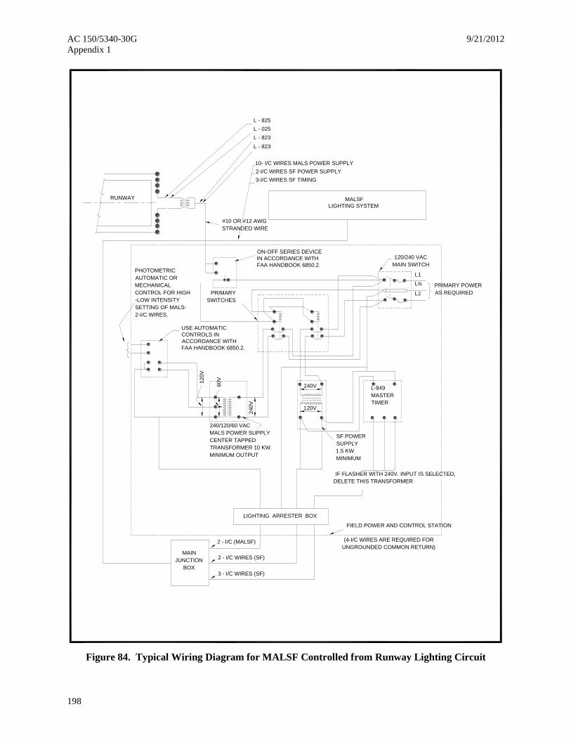
AC 150/5340-30G 9/21/2012
Appendix 1
198
Figure 84. Typical Wiring Diagram for MALSF Controlled from Runway Lighting Circuit
120/240 VAC
MAIN SWITCH
PRIMARY POWER
AS REQUIRED
L1
L2
LN
L-849
MASTER
TIMER
LIGHTING ARRESTER BOX
MAIN
JUNCTION
BOX
FIELD POWER AND CONTROL STATION
60V
24
0V
240V
120V
12
0V
(4-I/C WIRES ARE REQUIRED FOR
UNGROUNDED COMMON RETURN)
IF FLASHER WITH 240V. INPUT IS SELECTED,
DELETE THIS TRANSFORMER
SF POWER
SUPPLY
1.5 KW.
MINIMUM
2 - I/C (MALSF)
2 - I/C WIRES (SF)
3 - I/C WIRES (SF)
L - 825
MALSF
LIGHTING SYSTEM
L - 025
L - 823
L - 823
10- I/C WIRES MALS POWER SUPPLY
2-I/C WIRES SF POWER SUPPLY
3-I/C WIRES SF TIMING
#10 OR #12 AWG
STRANDED WIRE
RUNWAY
ON-OFF SERIES DEVICE
IN ACCORDANCE WITH
FAA HANDBOOK 6850.2.PHOTOMETRIC
AUTOMATIC OR
MECHANICAL
CONTROL FOR HIGH
-LOW INTENSITY
SETTING OF MALS-
2-I/C WIRES.
PRIMARY
SWITCHES
USE AUTOMATIC
CONTROLS IN
ACCORDANCE WITH
FAA HANDBOOK 6850.2.
240/120/60 VAC
MALS POWER SUPPLY
CENTER TAPPED
TRANSFORMER 10 KW.
MINIMUM OUTPUT

9/21/2012 AC 150/5340-30G
Appendix 1
199
Figure 85. Typical Field Wiring Circuits for MALSF
NOTES:
THE INSTALLATION CONFORMS TO THE APPLICABLE SECTION OF THE NATIONAL ELECTRICAL CODE AND LOCAL CODES.
INSTALL LIGHTING ARRESTERS FOR POWER AND CONTROL LINES AS REQUIRED.
WHERE REQUIRED INSTALL A COUNTERPOISE SYSTEM SPECIFIED IN THE PLANS.
INSTALL FUSES, CIRCUIT BREAKERS AND CUTOUTS IN ACCORDANCE WITH EQUIPMENT RATINGS.
CALCULATE THE MINIMUM WIRE SIZE TO BE USED BETWEEN THE POWER SUPPLY, MAIN JUNCTION BOX, AND LIGHT BARS FOR EACH INSTALLATION.
1.
2.
3.
4.
5.
CONNECT THE FLASHING LIGHTS AND THE STEADY BURNING LIGHTS INTO THE ELECTRICAL CIRCUITS IN ACCORDANCE WITH THE EQUIPMENTMANUFACTURER'S INSTRUCTIONS.
INSTALL THE PREFABRICATED METAL HOUSING AND THE EQUIPMENT ENCLOSURES IN ACCORDANCE WITH APPLICABLE SECTIONS OF ADVISORYCIRCULAR 150/5370-10 STANDARD SPECIFICATION OF CONSTRUCTION OF AIRPORTS.
INSTALL AND CHECK THE UNDERGROUND CABLES IN ACCORDANCE WITH THE APPLICABLE SECTIONS OF ITEM L-108 OF ADVISORY CIRCULAR 150/5370-10.
6.
7.
8.
GROUND EACH LIGHT BAR AND FLASHING LIGHT AS SPECIFIED IN THE INSTALLATION PLANS.
MAINTAIN NOT LESS THAN 114 VOLTS 60 Hz NOR MORE THAN 126 VOLTS 60 Hz AT LIGHTS.
A TYPICAL LOCATION FOR THE FIELD POWER AND CONTROL STATIONS IS NEAR THE 1000' [304.8 M] CROSS BAR. DO NOT INSTALL THE FIELD POWER AND
ALL JUNCTION BOXES (JB) ARE FURNISHED BY THE INSTALLATION CONTRACTOR.
POWER CIRCUITS ARE ASSIGNED NUMBERS 1 THROUGH 6 FOR REFERENCE PURPOSES.
9.
10.
11.
12.
CONTROL STATION CLOSER THAN 400' [121.9 M] TO THE MALS CENTERLINE BETWEEN STATION 0+00 AND 10+00.
6.6 AMPERE
RUNWAY SERIES
ISOLATINGTRANSFORMER
5-PAR-38150 WATT
LRUNWAY C
LAMPS
CONTROL STATIONSEE NOTE 12
3-I/C WIRESSF CIRCUITNO. 6
4-I/C WIRESSF CIRCUITNO. 6
2-I/C WIRESON/OFF CONTROL FROM
2-I/C WIRESMALS CIRCUIT NO. 2
2-I/C WIRESMALS CIRCUIT NO. 1
2-I/C WIRESMALS CIRCUIT NO. 3
2-I/C WIRESMALS CIRCUIT NO. 4
2-I/C WIRESMALS CIRCUIT NO. 6
2-I/C WIRESMALS CIRCUIT NO. 5
2-I/C WIRES
2-I/C WIRES
FIELD POWER AND
120/240 VACPOWER SUPPLY
3-I/C
SERIES LIGHTING CIRCUIT
28' [8.5 M] 28' [8.5 M]
200'
[60.9 M]
200'
[60.9 M]
200'
[60.9 M]
200'
[60.9 M]
200'
[60.9 M]
200'
[60.9 M]
JB
SF
LIGHTING CIRCUIT
RUNWAY THRESHOLD LIGHTS
200'
[60.9 M]
1000'
[304.8 M]
SEE
NOTE 12
1400'
[426.7 M]
INTENSITY SETTING OF MALS
AUTOMATIC, OR MECHANICAL2-I/C WIRES FOR PHOTOELECTRIC,
CONTROL FOR HIGH-LOW
13.

AC 150/5340-30G 9/21/2012
Appendix 1
200
Figure 86. Typical Installation Details for Frangible MALS Structures – 6 foot (1.8 m) Maximum
NO
TE
S:
1.
US
E W
IRE
SIZ
E A
S S
HO
WN
. C
ALC
UL
AT
E W
IRE
SIZ
ES
FO
R E
AC
H
IN
ST
AL
LA
TIO
N.
2.
WH
ER
E R
EQ
UIR
ED
IN
ST
AL
L C
OU
NT
ER
PO
ISE
SY
ST
EM
. I
NS
TA
LL
GR
OU
ND
RO
DS
AT
LE
AS
T E
VE
RY
1000'.
3.
US
E C
ON
DU
IT S
IZE
SH
OW
N.
4.
LE
AV
E 3
FE
ET
[0
.9 M
] S
LA
CK
IN
EA
CH
DIR
EC
T B
UR
IAL C
AB
LE
AT
EA
CH
LIG
HT
BA
R.
5.
CO
NC
RE
TE
CO
NF
OR
MS
TO
IT
EM
S P
-61
0 O
F A
C 1
50/5
370-1
0.
6.
EN
TE
R A
LL
CA
BL
ES
TH
RO
UG
H W
AT
ER
TIG
HT
SQ
UE
EZ
E C
ON
NE
CT
OR
S.
7.
SE
LE
CT
CO
ND
UIT
S A
ND
FIT
TIN
GS
TH
AT
AR
E S
UIT
AB
LY
PR
OT
EC
TE
D.
8.
GR
OU
ND
RO
DS
AR
E T
O B
E C
OP
PE
RW
ELD
OR
EQ
UA
L 5
/8"
DIA
. 8
' LO
NG
.
9.
IN
AR
EA
OF
HIG
H W
AT
ER
TA
BLE
OR
IN
LO
CA
TIO
NS
SU
BJE
CT
TO
FL
OO
DIN
G R
AIN
S,
FIL
L T
HE
UN
DE
RG
RO
UN
D J
UN
CT
ION
BO
X W
ITH
SIL
ICO
NE
RU
BB
ER
OR
SO
ME
OT
HE
R M
AT
ER
IAL
TO
EX
CLU
DE
TH
E
CO
LL
EC
TIO
N O
F W
AT
ER
.
LE
AV
E D
RIP
LO
OP
1-2
/C U
PP
ER
SJ
CA
BL
E C
UT
TO
RE
QU
IRE
D L
GT
H
2"
[5 C
M]
EM
T
CO
ND
UIT
(O
R
2.3
75
PIP
E [6
CM
])
6"
[15 C
M]
MA
XIM
UM
2-1
/C
2"
FR
AN
GIB
LE
CO
UP
LIN
G
PA
R 3
8 L
AM
P
15
0 W
-120V
. S
PO
T L
AM
P
LA
MP
HO
LD
ER
WIT
H
VE
RT
ICA
L A
ND
HO
RI-
ZO
NT
AL
AD
JU
ST
ME
NT
S
DE
TA
IL R
OT
AT
ED
90°
TO
SH
OW
SID
E V
IEW
OF
LA
MP
AS
SE
MB
LY
BU
FF
EN
D O
F E
MT
WIT
H
SA
ND
PA
PE
R F
OR
TIG
HT
FIT
(A
PP
LY
SM
AL
L A
MO
UN
T
OF
GR
EA
SE
BE
FO
RE
INS
ER
TIO
N)
L-8
23
FIG
UR
E 1
5 (
a)
3"x
3"x
1/8
" [7
.6 C
M X
7.6
CM
X 3
.1 M
M]
ME
TA
L A
NG
LE
IR
ON
ST
AK
E
30
" L
ON
G [0
.7 M
] W
ITH
2"
[5 C
M]
HU
B
AN
D C
AB
LE
CLA
MP
L-8
23
FIG
UR
E 1
5 (
b)
RE
CE
PT
AC
LE
2-I
/C L
-82
4 C
AB
LE
2'-6"
[0.7
M]
SE
E
DE
TA
IL
"A"
FO
R
CO
NN
EC
TO
R
DE
TA
IL
2"
HU
B W
ITH
CA
BLE
CLA
MP
2"
[5 C
M]
SLIP
FIT
TE
R
CO
MP
RE
SS
ION
NU
T
GR
OU
ND
LE
VE
L
2-I
/C
L-8
24 C
AB
LE
L-8
02 S
TA
KE
4-I
/C P
OW
ER
SU
PP
LY
(S
EE
NO
TE
1)
8"x
8"
[0.2
M X
0.2
M]
SQ
UA
RE
OR
8"
[0.2
M] D
IA.
CO
NC
RE
TE
AN
CH
OR
UN
LE
SS
OT
HE
R S
PE
CIF
IED
CE
NT
ER
LIN
E O
F
AP
PR
OA
CH
SY
ST
EM
4-I
/CUN
DE
RG
RO
UN
D
L-8
48 J
UN
CT
ION
BO
X
1-2
/C U
PP
ER
SJ C
AB
LE
CU
T T
O
RE
QU
IRE
D L
GT
H
LE
AV
E D
RIP
LO
OP
18"
MINIMUM
L-8
23
4-I
/C
LA
MP
HO
LD
ER
VE
RT
.
AD
JU
ST
PA
R 3
8 L
AM
P
150 W
- 1
20V
. S
PO
T L
AM
P
2-I
/C
CO
MP
RE
SS
ION
NU
T
BR
EA
KA
BLE
CO
UP
LIN
G
10 P
OLE
TE
RM
INA
L B
LO
CK
SE
E F
IG. 82 F
OR
CO
NN
EC
TIO
NS
SE
E D
ET
AIL
"A
" F
OR
CO
NN
EC
TO
R D
ET
AIL
HU
BS
AN
D
WA
TE
RT
IGH
T
CO
NN
EC
TO
RS
FO
R C
AB
LE
(SE
E N
OT
E 3
)
1"
[2.5
C
M] H
UB
S A
ND
WA
TE
R-
TIG
HT
CO
NN
EC
TO
RS
FO
R
L-8
24 C
AB
LE
GR
OU
ND
CLA
MP
4-I
/C C
AB
LE
S
FO
R P
OW
ER
SU
PP
LY
(SE
E N
OT
E 1
)
FU
SE
BLO
CK
DE
TA
IL C
JU
NC
TIO
N B
OX
IN
ST
AL
LA
TIO
N D
ET
AIL
S F
OR
ST
AT
ION
S 4
+00
AN
D 8
+0
0
DE
TA
IL B
LIG
HT
BA
R C
ON
FIG
UR
AT
ION
FO
R
ST
AT
ION
S 2
+00
TO
8+
00
DE
TA
IL A
IN
ST
AL
LA
TIO
N D
ET
AIL
S F
OR
EA
CH
FIX
TU
RE
SU
PP
OR
T IN
BA
R
L-8
48 F
RA
NG
IBLE
H F
RA
ME
CO
NC
RE
TE
FO
UN
DA
TIO
N
(IT
EM
P-6
10)
US
E A
ME
TA
L L
-802 S
TA
KE
WIT
H A
CO
NC
RE
TE
AN
CH
OR
AS
SH
OW
N IN
DE
TA
IL B
AS
AN
ALT
ER
NA
TE
CO
NS
TR
UC
TIO
N D
ET
AIL
US
E A
ME
TA
L
L-8
02 S
TA
KE
WIT
H A
CO
NC
RE
TE
AN
CH
OR
AS
SH
OW
N
IN D
ET
AIL
B A
S A
N
ALT
ER
NA
TE
CO
NS
TR
UC
TIO
N
DE
TA
IL
2"
[5 C
M ] B
RE
AK
AB
LE
CO
UP
LIN
G
ST
AN
DA
RD
2"
[5 C
M] N
OM
INA
L
SU
PP
OR
T (
FU
RN
ISH
ED
BY
INS
TA
LLA
TIO
N C
ON
TR
AC
TO
R)
GR
OU
ND
RO
D IF
RE
QU
IRE
D
JU
NC
TIO
N B
OX
(U
ND
ER
GR
OU
ND
) F
UR
NIS
HE
D
BY
IN
ST
ALLA
TIO
N C
ON
TR
AC
TO
R
(S
EE
NO
TE
9)
6' [1.8 M] MAXIMUM
18" [0.4 M]
2"
[5 C
M]
EM
T
CO
ND
UIT
(O
R
2.3
75
PIP
E [6
CM
])
6"
[15 C
M]
MA
XIM
UM
2"
[5 C
M]
EM
T
CO
ND
UIT
(O
R
2.3
75
PIP
E [6
CM
])
6"
[15 C
M]
MA
XIM
UM
2'-6"
[0.7
M]
2'-6"
[0.7
M]
2'-6"
[0.7
M]

9/21/2012 AC 150/5340-30G
Appendix 1
201
Figure 87. Typical Wiring for REILs Multiple Operation
NO
TE
S
1. T
HE
IN
ST
AL
LA
TIO
NS
SH
OU
LD
CO
NF
OR
M T
O T
HE
AP
PLIC
AB
LE
SE
CT
ION
S O
F T
HE
NA
TIO
NA
L E
LE
CT
RIC
AL C
OD
E A
ND
LO
CA
L C
OD
ES
.
2. LIG
HT
EN
ING
AR
RE
ST
ER
S F
OR
PO
WE
R A
ND
CO
NT
RO
L L
INE
S S
HO
ULD
BE
IN
ST
ALLE
D A
S R
EQ
UIR
ED
.
3.
FU
SE
S A
ND
CIR
CU
IT B
RE
AK
ER
S S
HO
ULD
BE
IN
AC
CO
RD
AN
CE
WIT
H
EQ
UIP
ME
NT
RA
TIN
GS
.
4.
TH
E R
UN
WA
Y E
ND
ID
EN
TIF
ER
LIG
HT
SY
ST
EM
IS
GR
OU
ND
ED
AS
SP
EC
IFIE
D I
N T
HE
PL
AN
S F
OR
TH
E IN
ST
ALLA
TIO
N.
5. LO
CA
L C
ON
TR
OL C
AN
BE
OB
TA
INE
D F
OR
RE
ILS
IF
RE
QU
IRE
D
FO
R T
HE
IN
ST
ALLA
ION
. T
HE
LO
CA
L S
WIT
CH
IS
AS
ST
AT
ED
IN C
HA
PT
ER
7.
6.
NO
EN
CLO
SU
RE
IS
RE
QU
IRE
D I
F T
HE
EQ
UIP
ME
NT
SH
OW
N IN
TH
E
HO
US
ING
IS
DE
SIG
NE
D F
OR
OU
TD
OO
R S
ER
VIC
E.
7.
TH
E L
IGH
T U
NIT
S A
ND
LO
CA
L C
ON
TR
OLS
AR
E IN
AC
CO
RD
AN
CE
WIT
H S
PE
CIF
ICA
TIO
N L
-849.
8. S
AM
PLE
CA
LC
ULA
TIO
N T
O D
ET
ER
MIN
E T
HE
MA
XIM
UM
DIS
TA
NC
E
BE
TW
EE
N T
HE
DIS
TR
IBU
TIO
N T
RA
NS
FO
RM
ER
AN
D T
HE
FU
RT
HE
ST
RE
ILS
LIG
HT
UN
IT U
SIN
G N
o. 12 A
WG
WIR
E (
RE
SIS
TA
NC
E=
1.6
2O
HM
S/
1000').
a.
LO
CA
L C
ON
DIT
ION
S
(1).
LO
AD
OF
2 R
EIL
S L
IGH
T U
NIT
S -
1K
W M
AX
IMU
M.
(2).
AV
AIL
AB
LE
VO
LT
AG
E F
RO
M D
IST
RIB
UT
ION
TR
AN
SF
OR
ME
R F
OR
R
EIL
S-2
40 V
OLT
S ±
5%
.
b.
CA
LC
ULA
TIO
NS
(1).
500 W
AT
TS
/LIG
HT
UN
IT X
2 L
IGH
T U
NIT
S=
4.1
6 A
MP
ER
ES
LO
AD
CU
RR
EN
T
240
VO
LT
S
(2).
240 X
5%
= 1
2 V
OLT
S P
ER
MIS
SIB
LE
LIN
E L
OS
S T
O H
AV
E R
AT
ED
V
OLT
AG
E A
T F
UR
TH
ES
T F
IXT
UR
E.
(3).
1.6
2 O
HM
S/1
000' X
4.1
6 A
MP
ER
ES
LO
AD
CU
RR
EN
T =
6.7
4 V
OLT
S/1
000'.
(4).
12 V
OLT
S P
ER
MIS
SIB
LE
VD
= 1
780 F
EE
T
6.7
4 V
D/1
000'
(5).
SIN
CE
TW
O W
IRE
S A
RE
RE
QU
IRE
D T
HE
MA
XIM
UM
DIS
TA
NC
E IS
1780' =
890 F
EE
T
(6).
TO
DE
TE
RM
INE
TH
E M
AX
IMU
M D
IST
AN
CE
US
ING
OT
HE
R W
IRE
SIZ
ES
,
O
BT
AIN
TH
E R
ES
IST
AN
CE
OF
TH
E W
IRE
PE
R 1
000' A
ND
FO
LLO
W
T
HE
AB
OV
E P
RO
CE
DU
RE
.
9. T
HE
CO
NT
RO
L S
TA
TIO
N M
AY
BE
A R
EM
OT
E C
ON
TR
OLLE
D S
WIT
CH
,
RA
DIO
CO
NT
RO
L, O
R A
UT
OM
AT
IC C
ON
TR
OL (
PH
OT
OC
ELL O
R T
IMIN
G
DE
VIC
ES
), O
R C
ON
TR
OL F
RO
M R
UN
WA
Y E
DG
E L
IGH
TIN
G C
IRC
UIT
.
120/2
40V
, 60 H
z
OF
F
ON
CO
NT
RO
L S
TA
TIO
N
(SE
E N
OT
E 9
)
PR
EF
AB
RIC
AT
ED
ME
TA
L
HO
US
ING
FO
R E
LE
CT
RIC
AL
EQ
UIP
ME
NT
OR
VA
ULT
(S
EE
NO
TE
6)
PR
IMA
RY
PO
WE
R
AS
RE
QU
IRE
D
(SE
E N
OT
E 3
)
OU
TP
UT
- 2
40 V
AC
60 H
ER
TZ
, 1
KW
MA
XIM
UM
EQ
UIP
ME
NT
LO
AD
2-1
C W
IRE
S (
SIZ
E
TO
BE
CA
LC
ULA
TE
D)
(SE
E N
OT
E 8
)
4-1
C I
F R
EQ
UIR
ED
TH
RE
SH
OLD
RE
IL
LIG
HT
EX
IST
ING
RU
NW
AY
LIG
HT
ING
CIR
CU
ITR
EIL
(SE
E N
OT
E
7)
RU
NW
AY
2

AC 150/5340-30G 9/21/2012
Appendix 1
202
Figure 88. Typical Wiring for REIL Series Operation
NO
TE
S
1.
INS
TA
LL
ME
DIU
M I
NT
EN
SIT
Y F
EE
DE
R C
AB
LE
S I
N C
OM
MO
N T
RE
NC
H W
ITH
RE
IL F
EE
DE
R C
AB
LE
S.
2.
AN
AD
DIT
ION
AL
LO
AD
OF
UP
TO
3K
W
MA
Y B
E A
DD
ED
TO
TH
E R
EG
UL
AT
OR
IF
TH
E R
EIL
S U
NIT
S A
RE
CO
NN
EC
TE
D I
NT
O T
HE
RU
NW
AY
LIG
HT
ING
CIR
CU
IT.
3.
TH
E R
EIL
S U
NIT
S A
RE
CO
NN
EC
TE
D I
NT
O T
HE
EL
EC
TR
ICA
L C
IRC
UIT
S IN
AC
CO
RD
AN
CE
WIT
H T
HE
EQ
UIP
ME
NT
MA
NF
AC
TU
RE
R'S
RE
CO
MM
EN
DA
TIO
NS
.
N CC
B1
0
B3
0
B1
00
L-8
12
RE
GU
LA
TO
R
4 K
W
S1
S2
L1L2
RA
TE
D I
NP
UT
VO
LT
AG
E
EX
TE
RN
AL
JU
MP
ER
LN
RC
LN
RB
LN
RA
L 2
L 1
L-8
16
TY
PE
II
AS
SE
MB
LY
B A N
CC
1
CC
B1
0
B3
0
B1
00
1A
1B
2A
2B
SP
ST
SW
ITC
H
3 P
OS
ITIO
N
TO
GG
LE
SW
ITC
H
(ON
-ON
-ON
)
2 S
PS
T
TO
GG
LE
SW
ITC
HE
S
L-8
21
CO
NT
RO
L P
AN
EL
ME
DIU
M I
NT
EN
SIT
Y R
UN
WA
Y
LIG
HT
ING
CIR
CU
IT S
EE
NO
TE
1
L-8
49
SE
RIE
S
AD
AP
TE
R U
NIT
RE
IL
RE
IL
R
U
N
W
A
Y
12
0/2
40
V,
60
Hz
C
WIT
H C
UR
RE
NT
SE
NS
ING
OU
TP
UT

9/21/2012 AC 150/5340-30G
Appendix 1
203
Figure 89. FAA L-880 Style B (Constant Current) System Wiring Diagram
(CO
NS
TA
NT
CU
RR
EN
T)
SY
ST
EM
WIR
ING
DIA
GR
AM
NO
T T
O S
CA
LE
FA
A L
-880 S
TY
LE
B
3
IND
ICA
TE
SP
RIM
AR
YR
EC
EP
TA
CLE
INC
OM
ING
= P
OW
ER
LE
AD
S W
ITH
AP
PR
OP
RIA
TE
L-8
23
CO
NN
EC
TO
RS
, U
SE
L-8
24 T
YP
E C
#8 A
WG
= C
ON
SO
LID
AT
ING
HA
RN
ES
S, T
ILT
SW
ITC
H W
IRE
EN
DS
(B
LA
CK
& G
RE
EN
LE
AD
S)
= 1
00W
, 6.6
/6.6
A IS
OLA
TIO
N T
RA
NS
FO
RM
ER
= 3
00W
, 6.6
/6.6
A IS
OLA
TIO
N T
RA
NS
FO
RM
ER
AR
E #
14 A
WG
= T
ILT
SW
ITC
H L
EA
DS
, U
SE
#14 A
WG
MIN
(L-8
23 C
ON
NE
CT
OR
KIT
S)
543
6.6
AM
PS
FE
ED
PO
WE
R
CU
RR
EN
TC
ON
ST
AN
T
1 2
11
21
11
11
1
SE
CO
ND
AR
Y
IND
ICA
TE
SS
EC
ON
DA
RY
PR
IMA
RY
IND
ICA
TE
S
RE
CE
PT
AC
LE
IND
ICA
TE
S
PLU
G
PLU
G
LIG
HT
AS
SY
UN
IT
MA
ST
ER
3
5
4
PA
PI
PA
PI
LIG
HT
UN
IT
AS
SY
SLA
VE
LIG
HT
5
SLA
VE
AS
SY
UN
IT
3
4
PA
PI
LIG
HT
5
4
3
AS
SY
UN
IT
SLA
VE
PA
PI
FA
A L
-880
ST
YLE
"B
" S
YS
TE
M (
WIT
H T
ILT
SW
ITC
HE
S)
UN
IT A
UN
IT C
UN
IT B
UN
IT D
IND
ICA
TE
S F
IELD
WA
TE
RP
RO
OF
CU
ST
OM
ER
SP
LIC
E
3 L
AM
PS
PE
R L
IGH
T U
NIT
NO
TE
: D
ele
te u
nits C
& D
for
2-b
ox s
yste
m

AC 150/5340-30G 9/21/2012
Appendix 1
204
Figure 90. FAA L-880 Style A (Constant Voltage) System Wiring Diagram
431 2
NO
TE
: D
ELE
TE
UN
ITS
C &
D F
OR
2-B
OX
SY
ST
EM
FIE
LD
WA
TE
RP
RO
OF
CU
ST
OM
ER
SP
LIC
E
LE
GE
ND
LIG
HT
AS
SY
UN
IT "
A"
MA
ST
ER
PA
PI
LIG
HT
AS
SY
UN
IT "
B"
MA
ST
ER
PA
PI
LIG
HT
AS
SY
UN
IT "
C"
MA
ST
ER
PA
PI
LIG
HT
AS
SY
UN
IT "
D"
MA
ST
ER
PA
PI
33
32
44
UN
ITA
SS
EM
BLY
PO
WE
R A
ND
CO
NT
RO
L
2
22
34
A
SS
Y,
US
E #
14 A
WG
MIN
U
NIT
AS
SY
1-X
TE
RM
INA
LS
, U
SE
#8 A
WG
MIN
= T
ILT
SW
ITC
H L
EA
DS
FR
OM
PR
EV
IOU
S L
IGH
T U
NIT
AS
SY
TB
1 T
ER
MIN
ALS
TIL
T S
WIT
CH
A &
B, U
SE
#14
= T
ILT
SW
ITC
H L
EA
DS
FR
OM
PO
WE
R &
CO
NT
RO
L U
NIT
= O
UT
GO
ING
PO
WE
R F
EE
D F
RO
M P
OW
ER
& C
ON
TR
OL
= C
ON
SO
LID
AT
ING
HA
RN
ES
S, 4/#
14 A
WG
LE
AD
S
ON
/OF
F
TO
LIG
HT
UN
ITS
PO
WE
R
AC
IN
PU
T
TB
1
TO
PR
OJE
CT
OR
#4
CO
NS
OLID
AT
ING
HA
RN
ES
S
LE
AD
CO
LO
R C
OD
ES
RE
D =
PO
WE
R L
EA
DW
HIT
E =
PO
WE
R L
EA
DB
LA
CK
= T
ILT
SW
ITC
H L
EA
DG
RE
EN
= T
ILT
SW
ITC
H L
EA
D
TA
BLE
1
INC
OM
ING
PO
WE
R F
EE
D:
208 -
240V
, 60 H
zO
R250V
, 50 H
z
X8
X7
X6
X5
X4
X3
X2
X1
UN
IT3 L
AM
P, 4 P
RO
JE
CT
OR
TIL
T S
W B
TIL
T S
W A
RE
MO
TE
B
RE
MO
TE
A
LIN
E B
LIN
E A
TO
PR
OJE
CT
OR
#3
TO
PR
OJE
CT
OR
#2
TO
PR
OJE
CT
OR
#1
NO
RT
H
PO
INT
PC
1
PO
WE
R C
ON
TR
OL
AW
G M
IN
SE
E T
AB
LE
1

9/21/2012 AC 150/5340-30G
Appendix 1
205
Figure 91. PAPI Light Housing Unit (LHU) Installation Detail
NO
T T
O S
CA
LE
AIM
TO
WA
RD
TH
RE
SH
OLD
FR
AN
GIB
LE
CO
UP
LIN
G (
TY
P)
21"
[533.5
mm
]21"
[533.5
mm
]
42"
[1067 m
m]
22" [539 mm]10" [254 mm]
11"
[279 mm]
12"
[305m
m]
17"
[432 m
m]
42" [1067 mm]
36" [914 mm]
SEE NOTE 2
FIN
ISH
ED
GR
AD
E
SEE NORE 3
1" [25 mm]
2"
[51 m
m]
PV
C S
CH
. 40 C
ON
DU
IT
BE
TW
EE
N P
AP
I U
NIT
S
CO
NC
RE
TE

AC 150/5340-30G 9/21/2012
Appendix 1
206
Figure 92. Typical Installation Details for Runway End Identifier Lights (REILs)
SP
EC
IFIC
AT
ION
L-8
49
PO
WE
R S
UP
PLY
SP
EC
IFIC
AT
ION
L-8
49
OP
TIC
AL S
YS
TE
M
FR
AN
GIB
LE
CO
UP
LIN
G
(SE
E N
OT
E 5
)
CO
NC
RE
TE
FO
UN
DA
TIO
N
(SE
E N
OT
E 2
)
GR
OU
ND
ING
RO
D
PO
WE
R A
ND
CO
NT
RO
L W
IRE
S
(SE
E N
OT
E 1
& 3
)
FR
ON
T V
IEW
18"
[457 m
m] M
IN
6"
[152.4
mm
] (M
IN)
BE
LO
W L
OC
AL
FR
OS
T L
INE
36" [914.4 mm]
MAX
HO
RIZ
ON
TA
L
PLA
N T
HR
OU
GH
TH
E R
UN
WA
Y
CE
NT
ER
LIN
E
EN
D V
IEW
NO
TE
S:
1.
CO
NF
OR
M I
NS
TA
LLA
TIO
NS
TO
TH
E A
PP
LIC
AB
LE
SE
CT
ION
S O
F T
HE
NA
TIO
NA
L E
LE
CT
RIC
AL C
OD
E A
ND
LO
CA
L C
OD
ES
.
2.
TH
E S
IZE
OF
TH
E C
ON
CR
ET
E F
OU
ND
AT
ION
SH
OU
LD
BE
IN
DIC
AT
ED
ON
TH
E C
ON
ST
RU
CT
ION
PLA
NS
.
3.
TH
E T
OP
OF
TH
E C
ON
CR
ET
E F
OU
ND
AT
ION
SH
OU
LD
BE
SLO
PE
D T
O D
RA
IN T
OW
AR
D T
HE
ED
GE
OF
TH
E F
OU
ND
AT
ION
.
TH
E G
RO
UN
D S
UR
RO
UN
DIN
G S
HO
ULD
BE
NO
MO
RE
TH
AN
TH
RE
E I
NC
HE
S B
ELO
W T
HE
TO
P O
F T
HE
FO
UN
DA
TIO
N.
4.
IN
ST
ALL P
OW
ER
AN
D C
ON
TR
OL W
IRE
S I
N A
CC
OR
DA
NC
E W
ITH
TH
E A
PP
LIC
AB
LE
SE
CT
ION
S O
F IT
EM
L-1
08 O
F
ST
AN
DA
RD
SP
EC
IFIC
AT
ION
S F
OR
CO
NS
TR
UC
TIO
N O
F A
IRP
OR
TS
.
5.
PR
OV
IDE
FR
AN
GIB
LE
CO
UP
LIN
GS
FO
R T
HE
LIG
HT
UN
IT A
ND
SU
PP
LY
. T
HE
OU
TS
IDE
DIA
ME
TE
R O
F T
HE
SU
PP
OR
TS
CA
N B
E 2
.197 IN
[55.8
0 m
m]
OR
2.3
75 IN
[60.3
2 m
m].
6.
BR
EA
KIN
G-P
OIN
T F
RA
NG
IBLE
CO
UP
LIN
G S
HO
ULD
BE
LO
CA
TE
D 3
IN
[76.2
mm
] M
AX
AB
OV
E G
RA
DE
.

9/21/2012 AC 150/5340-30G
Appendix 1
207
Figure 93. Configuration “A” Electrical Power
E/G
CONSTANT CURRENT REGULATORS
A-1 ENGINE GENERATOR IN VAULT
NOTE :
TRANSFORMERS, DISCONNECTS,
ISOLATION SWITCHES,
PROTECTIVE DEVICES, POWER
QUALITY SENSING DEVICES,
ETC. NOT SHOWN.
PRIME
PRIME
E/G
A-2 ENGINE GENERATOR ADJACENT TO VAULT
FEEDER IN CONCRETE ENCASED DUCT OR
STEEL CONDUIT, WITHOUT SPLICES OR
INTERMEDIATE MANHOLES.
PRIME
E/G
CONSTANT
CURRENT
REGULATORS
ENCLOSURE
ENG/GEN VAULT
DUAL FEEDER
CONSTANT
CURRENT
REGULATORS
A-3 ENGINE GENERATOR REMOTE FROM VAULT
E/G E/G E/G
CONSTANT
CURRENT
REGULATORS
VAULTENG/GEN
A-4 AGENCY PRIME POWER AT VAULT

AC 150/5340-30G 9/21/2012
Appendix 1
208
Figure 94. Typical KVA Input Requirements
A
V
1. Only qualified personnel
should take voltage and
current measurements.
2. Suitable meters should be
used to take voltage and
current readings.
3. Power factor correcting
capacitors can be obtained
in accordance with the
regulator manufacturer's
recommendations to raise
the power factor above 0.7.
NOTES :
CONSTANT CURRENT
REGULATOR
OUTPUT
TO SERIES
CIRCUIT
CONTROL
CIRCUITS
VOLTMETER ADEQUATE
FOR HIGH VOLTAGE
AMMETER
TYPICAL CALCULATIONS
1. Measured KVA
a. Volts = 2400V
b. Amperes = 17.0A
c. KVA Input = Volts x Amperes 2400 x 17.0 = 40.8KVA
1000 1000
2. Calculated KVA
a. KW = 30
b. Efficiency = 0.92 (obtain this value from applicable advisory circular
for regulator, e.g., Specification L-828)
c. Power Factor = 0.7 (same as note for b. above)
d. KVA Input = KW 30 = 46.6KVA
Efficiency x Power Factor 0.92 x 0.7
3. It is normal for the measured KVA to be less than the calculated KVA,
however, the calculated KVA should be used for design purposes. The
difference in the values can be caused by the regulator having a higher
efficiency and power factor than the values used in the calculations or
by the load on the regulator.
INPUT POWER
SEE NOTE 1.
MEASUREMENTS.

9/21/2012 AC 150/5340-30G
Appendix 1
209
Figure 95. Typical Wiring Diagram for Configuration “A” Electrical Power
81
82
74
73
83
ST
AN
DB
Y O
N
RE
D L
IGH
TT
O IN
DIC
AT
EW
HE
N S
TA
ND
BY
IS R
UN
NIN
G
"EN
GIN
E -
GE
NE
RA
TO
R S
TA
RT
" S
WIT
CH
IS A
PP
RO
AC
HIN
G
}U
NL
ES
S O
TH
ER
WIS
E S
PE
CIF
IED
, T
OE
NG
INE
GE
NE
RA
TO
R S
WIT
CH
BO
AR
D(S
EE
NO
TE
4)
RE
LA
Y
OP
ER
AT
ION
OF
EN
GIN
E G
EN
ER
AT
OR
SE
T,
SE
E N
OT
E 5
)
DIS
TR
IBU
TIO
NT
RA
NS
FO
RM
ER
OU
TP
UT
TO
LIG
HT
ING
CIR
CU
IT
INP
UT
2
40
0V
OL
TS
A
C
CO
NT
RO
LL
ED
PR
IMA
RY
HIG
H-V
OLT
AG
EF
US
ED
CU
TO
UT
PR
IME
PO
WE
R -
TR
AN
SF
OR
ME
R(S
EE
NO
TE
1)
TR
AN
SF
OR
ME
R
TR
AN
SF
OR
ME
RS
WIT
CH
BY
PA
SS
TO
GE
NE
RA
TO
RO
F E
NG
INE
GE
NE
RA
TO
R S
ET
L-8
28
RE
GU
LA
TO
R
(SE
E N
OT
E 2
)D
EV
ICE
RE
MO
TE
OIL
SW
ITC
H
81
82
75
74
73
72
71
TR
AN
SF
OR
ME
RS
IN
TH
E P
RIM
E P
OW
ER
AN
D T
HE
RE
GU
LA
TO
R I
NP
UT
CIR
CU
ITS
AR
E N
OT
RE
QU
IRE
D
PR
OV
IDE
A B
YP
AS
S S
WIT
CH
TO
PE
RM
IT R
UN
NIN
GT
HE
EN
GIN
E G
EN
ER
AT
OR
ON
MA
NU
AL
ST
AR
T-S
TO
P
TH
E R
EL
AY
SH
OW
N I
N T
HE
RE
GU
LA
TO
R'S
OP
ER
AT
E U
ND
ER
NO
-LO
AD
CO
ND
ITIO
NS
.
AT
CA
TE
GO
RY
II
LO
CA
TIO
NS
, U
SE
A R
EM
OT
E
EN
GIN
E-G
EN
ER
AT
OE
R W
HE
N C
AT
EG
OR
Y II
LIG
HT
ON
TH
E L
-821
PA
NE
L IN
DIC
AT
ES
"S
TA
ND
BY
ON
" W
HE
N T
HE
EN
GIM
NE
-GE
NE
RA
TO
R S
ET
IS
IF H
IGH
-VO
LT
AG
E A
ND
LO
W V
OLT
AG
E
EN
GIN
E-G
EN
ER
AT
OR
, P
RO
VID
E T
HE
NE
CE
SS
AR
YA
CC
ES
SO
RIE
S A
ND
SE
CT
ION
AL
IZE
TH
E
SU
PP
LIE
D B
Y S
TA
ND
BY
PO
WE
R.
TH
E S
EQ
UE
NC
E O
F O
PE
RA
TIO
N O
F T
HE
SE
T I
S I
N A
CC
OR
DA
NC
E W
ITH
MA
NU
FA
CT
UR
ER
'ST
RA
NS
FE
R S
WIT
CH
AN
D E
NG
INE
-GE
NE
RA
TO
R
RE
CO
MM
EN
DA
TIO
NS
.
RE
GU
LA
TIO
NS
AR
E S
UP
PL
IED
BY
A S
ING
LE
RE
QU
IRE
D L
OA
DS
FR
OM
LO
AD
S N
OT
TO
BE
CO
NT
RO
LL
ED
SW
ITC
H O
N T
HE
L-8
21
PA
NE
L T
OA
CT
IVA
TE
TH
E C
IRC
UIT
RE
QU
IRE
D T
O S
TA
RT
WE
AT
HE
R
IS A
PP
RO
AC
HIN
G. A
RE
D IN
DIC
AT
OR
RU
NN
ING
.
CO
NT
RO
L C
IRC
UIT
IS
NO
T R
EQ
UIR
ED
IF
TH
EE
NG
INE
GE
NE
RA
TO
R I
S S
ET
IS
DE
SIG
NE
D T
O
SW
ITC
H I
N A
CC
OR
DA
NC
E W
ITH
FA
A-E
-208
3.
TO
FA
CIL
ITA
TE
SE
RV
ING
. S
EL
EC
T A
BY
-PA
SS
IF A
SU
ITA
BL
E H
IGH
VO
LT
AG
E A
UT
OM
AT
ICS
WIT
CH
ING
SY
ST
EM
IS
US
ED
.
1.
2.
3.
4.
5.
6.
NO
TE
S:
240
0 V
OLT
S A
C
(PR
EV
EN
TS
NO
-LO
AD
FO
R U
SE
WH
EN
CA
TE
GO
RY
II W
EA
TH
ER
CO
NT
RO
L T
OW
ER
VA
ULT

AC 150/5340-30G 9/21/2012
Appendix 1
210
Figure 96. Typical Equipment Layout for Configuration “A” Electrical Power
NO
TE
S
1. T
HE
TR
AN
SF
ER
SW
ITC
H IS
NO
W R
EW
IRE
D T
O B
E M
OU
NT
ED
ON
TH
E E
NG
INE
GE
NE
RA
TO
R M
OU
NT
ING
PA
D. IT
MA
Y B
E W
ALL
MO
UN
TE
D O
R IN
ST
ALL
ED
AT
AN
Y C
ON
VE
NIE
NT
LO
CA
TIO
N.
2. T
YP
ICA
L F
LO
OR
SP
AC
ES
FO
R A
37.5
KV
A E
NG
INE
GE
NE
RA
TO
RS
ET
WIT
H A
UX
ILIA
RY
EQ
UIP
ME
NT
AR
E 1
2' W
IDT
H X
16' LE
NG
TH
[3.6
M W
IDT
H X
4.8
M L
EN
GT
H] A
ND
15' W
IDT
H X
17' LE
NG
TH
[4.5
M W
IDT
H X
5.1
M L
EN
GT
H] R
ES
PE
CT
IVE
LY
. S
PA
CE
S F
OR
UN
ITS
LA
RG
ER
TH
AN
75 K
VA
SH
OU
LD
BE
IN
AC
CO
RD
AN
CE
WIT
H
EQ
UIP
ME
NT
LA
YO
UT
FO
R C
ON
FIG
UR
AT
ION
"A
" P
OW
ER
DE
TA
IL "
A"
MU
FF
LE
R
TR
AN
SF
OR
ME
RS
(SE
E F
IGU
RE
95)
TR
AN
SF
ER
SW
ITC
H(S
EE
NO
TE
1)
EN
GIN
EG
EN
ER
AT
OR
FU
EL L
INE
SC
ON
DU
IT
SE
RIE
S O
UT
PU
T
CA
BLE
WIR
EW
AY
GR
OU
ND
RO
D A
ND
CLA
MP
L-8
28
RE
GU
LA
TO
R
SE
RIE
S
'CU
T-O
UT
CO
NT
RO
L C
IRC
UIT
WIR
EW
AY
EN
CLO
SE
D
HIG
H V
OLT
AG
E
PR
IME
PO
WE
R
RE
MO
TE
CO
NT
RO
LLE
D
PR
IMA
RY
OIL
SW
ITC
H
CO
ND
UIT
SU
PP
OR
T
TO
RE
MO
TE
CO
NT
RO
LLE
D
PR
IMA
RY
OIL
SW
ITC
H
HIG
H V
OLT
AG
EF
US
E C
UT
-OU
TS
CO
ND
UIT
SU
PP
OR
T
CO
ND
UIT
SU
PP
OR
T
CO
ND
UIT
EX
HA
US
T P
IPE
TO
MU
FF
LE
R
(SE
E D
ET
AIL
A)
TO
BA
TT
ER
IES
FLE
XIB
LE
AIR
DU
CT
FLE
XIB
LE
PIP
E
SH
OR
T
NIP
PLE
OU
TS
IDE
AIR
IN
TA
KE
TO
EN
GIN
E-G
EN
ER
AT
OR
SE
T
EX
HA
US
T P
IPE
SLO
PE
EN
D 3
" [7
6 c
m] B
ELO
W B
EN
D
OU
TS
IDE
AIR
EX
HA
US
T O
F
EN
GIN
E -
GE
NE
RA
TO
R S
ET
EX
HA
US
T P
IPE
WA
LL P
LA
TE
PIP
E
HA
NG
ER
MA
NU
FA
CT
UR
ER
'S R
EC
OM
ME
ND
AT
ION
S.
TO
TR
AN
SF
OR
ME
RS
IN
PR
IME
PO
WE
R
CIR
CU
IT A
ND
RE
GU
LA
TO
R IN
PU
T C
IRC
UIT

9/21/2012 AC 150/5340-30G
Appendix 1
211
Figure 97. Configuration “B” Electrical Power

AC 150/5340-30G 9/21/2012
Appendix 1
212
Figure 98. Typical Wiring Diagram for Configuration “B” Electrical Power
CO
NT
RO
L T
OW
ER 73
74
81
82
83
71
72
73
74
75
81
82
83
VA
UL
T
RE
MO
TE
CO
NT
RO
LL
ED
PR
IMA
RY
OIL
SW
ITC
H
GA
NG
ED
FU
SE
D O
UT
PU
T
PR
IME
PO
WE
R-2
40
0 V
OL
TS
AC
AL
TE
RN
AT
E P
RIM
E P
OW
ER
24
00
VO
LT
S A
C
TR
AN
SF
OR
ME
RS
AU
TO
MA
TIC
TR
AN
SF
ER
LO
W V
OL
TA
GE
TR
AN
SF
ER
SW
ITC
H
NO
TE
:T
HE
TR
AN
SF
OR
ME
RS
SH
OW
N A
RE
NO
T R
EQ
UIR
ED
IF A
SU
ITA
BL
E H
IGH
VO
LT
AG
E A
UT
OM
AT
IC S
WIT
CH
-IN
G S
YS
TE
M I
S U
SE
D.
TR
AN
SF
OR
ME
R
INP
UT
24
00
VO
LT
S A
C
OU
TP
UT
TO
LIG
HT
ING
CIR
CU
IT
DIS
TR
IBU
TIO
N T
RA
NS
FO
RM
ER

9/21/2012 AC 150/5340-30G
Appendix 1
213
Figure 99. Typical Wiring Diagram for Configuration “C” Power
L-821
CONTROL PANEL
IN TOWER
VAULT
REMOTE CONTROLLED
PRIMARY OIL SWITCH
PRIME
POWER
L-828
REGULATOR
TO PRIME
POWER
120VOLT 60 Hz
FROM SOURCE
CONNECTED TO
PRIME POWER
CABLES
TO SERIES
CIRCUIT
CONTROL
CABLE

AC 150/5340-30G 9/21/2012
Appendix 1
214
Figure 100. Flexible Pavement or Overlay Installation
NOT TO SCALE
COMPOUNDCEMENTING
NOTE: APPLY THIN LAYER OF SELF-LEVELING SILICONE (RTV118)
RING AND LIGHTHEIGHT OF BASE, FLANGE
EQUAL
3/4" [19mm]
DIAMETER OF FLANGELARGE CORE DRILL
EXISTING
FLEXIBLE
(RECOMMENDED METHOD)
CORE DRILL
SECTIONTOP
SEE DETAIL 'X'
FLANGE RING
FIXTUREINSET LIGHT
DIAMETER OF FLANGE RING W/PAVEMENT
PAVEMENT RING
RIGID CEMENTING
L-868 STEEL BASE
SPACER RING AS REQUIRED
FLANGE RING W/
FLEXIBLE LIQUID SEALER, P-605
PAVEMENT SURFACE
BASE
EXISTING
(PRIOR TO PAVING)
NEW CONCRETE
FIXTUREINSET LIGHT
5/8" [16mm] PLYWOOD COVER& 1/8" [3 mm] MUD PLATE
ALIGNMENT JIG
COMPLETED INSTALLATIONSTEP 4STEP 3
DETAIL 'X'
STEP 1
FLEXIBLE PAVEMENT OR OVERLAY INSTALLATION
(AFTER PAVING AND COMPACTING)
STEP 2
BETWEEN L-868 BASE, SPACERS, AND FLANGE RING
RING W/PAVEMENT RINGPLUS 1/2" [13mm]
PAVEMENT
OR OVERLAY
RING PLUS 1/2" [13mm]
SECTION
PAVEMENT OR
COMPACTED BASE
ANCHOR
NOTE: TYPICAL INSTALLATION IN NEW FLEXIBLE PAVEMENT OR OVERLAY OF FLEXIBLE OR RIGID (PCL) PAVEMENT.
COMPOUND P-606
TOP OF PAVEMENT RING 1/8" [3mm]
BELOW PAVEMENT SURFACE
2' TO 4" [51mm -102 mm]
MINIMUM 3/4" [19mm]
BOLT PROTRUSION
DIAMETER

9/21/2012 AC 150/5340-30G
Appendix 1
215
Figure 101. Use of Alignment Jig, No Reference Edge Available, Non-adjustable Base and Conduit
System
NO
TE
S:
1.
2.
3.
PO
SIT
ION
TH
E B
AS
E T
O P
ER
MIT
PA
SS
AG
E O
F P
AV
ING
MA
CH
INE
AN
D T
O A
CC
OM
MO
DA
TE
TH
E F
LA
NG
E R
ING
AN
D F
IXT
UR
E.
TH
ICK
ER
FL
AN
GE
RIN
GS
OR
SP
AC
ER
RIN
GS
MA
Y B
E U
SE
D F
OR
CO
RR
EC
TIN
G S
PA
CIN
G. H
OW
EV
ER
, P
OS
ITIO
NIN
G T
HE
BA
SE
TO
O H
IGH
MA
Y R
ES
ULT
IN
A M
OR
E C
OS
TLY
CO
RR
EC
TIV
E A
CT
ION
.
IN S
ET
TIN
G T
HE
BA
SE
ELE
VA
TIO
N, A
LLO
W F
OR
AT
LE
AS
T 1
/2 IN
[13 m
m] V
AR
IAT
ION
IN
TH
EO
RE
TIC
AL P
AV
EM
EN
T S
UR
FA
CE
EL
EV
AT
ION
PL
US
1/4
IN
CH
(6
mm
) A
DD
ITIO
NA
L S
AF
ET
Y M
AR
GIN
.
EL
EV
AT
ION
IS
CR
ITIC
AL
(SE
E N
OT
ES
)
3"
[76 m
m] (A
PP
RO
X.)
BE
LO
W T
HE
OR
ET
ICA
L
PA
VE
ME
NT
SU
RF
AC
E
CO
VE
R/S
PA
CE
RS
(AS
RE
QU
IRE
D)
AL
IGN
ME
NT
JIG
AN
CH
OR
RIN
G
ST
EE
L R
EIN
FO
RC
EM
EN
T
CA
GE
#4
BA
RS
CO
ND
UIT
OP
EN
ING
L 8
68
BA
SE
3"
[76 m
m] M
IN.
12
" [3
05
mm
]
MIN
IMU
M
6"
[15
2 m
m]
MIN
IMU
M
VA
RIE
S
CO
MP
AC
TE
D
SU
BB
AS
E
4"
[10
2 m
m]
CO
NC
RE
TE
AN
CH
OR
AD
JU
ST
ME
NT
LE
GS

AC 150/5340-30G 9/21/2012
Appendix 1
216
Figure 102. Use of Alignment Jig, Reference Edge Available, Non-adjustable Base and Conduit
System
NO
TE
S:
1.
2.
3.
PO
SIT
ION
TH
E B
AS
E T
O P
ER
MIT
PA
SS
AG
E O
F P
AV
ING
MA
CH
INE
AN
D T
O A
CC
OM
MO
DA
TE
TH
E F
LA
NG
E R
ING
AN
D F
IXT
UR
E.
TH
ICK
ER
FL
AN
GE
RIN
GS
OR
SP
AC
ER
RIN
GS
MA
Y B
E U
SE
D F
OR
CO
RR
EC
TIN
G S
PA
CIN
G. H
OW
EV
ER
, P
OS
ITIO
NIN
G T
HE
BA
SE
TO
O H
IGH
MA
Y R
ES
ULT
IN
A M
OR
E C
OS
TLY
CO
RR
EC
TIV
E A
CT
ION
.
IN S
ET
TIN
G T
HE
BA
SE
ELE
VA
TIO
N, A
LLO
W F
OR
AT
LE
AS
T 1
/2 IN
[13 m
m] V
AR
IAT
ION
IN
TH
EO
RE
TIC
AL P
AV
EM
EN
T S
UR
FA
CE
EL
EV
AT
ION
PL
US
1/4
IN
CH
(6
mm
) A
DD
ITIO
NA
L S
AF
ET
Y M
AR
GIN
.
EL
EV
AT
ION
IS
CR
ITIC
AL
(SE
E N
OT
ES
)
3"
[76 m
m] (A
PP
RO
X.)
BE
LO
W T
HE
OR
ET
ICA
L
PA
VE
ME
NT
SU
RF
AC
E
CO
VE
R/S
PA
CE
RS
(AS
RE
QU
IRE
D)
ALIG
NM
EN
T J
IG
AN
CH
OR
RIN
GE
XIS
TIN
G
PA
VE
ME
NT
ST
EE
L R
EIN
FO
RC
EM
EN
T
CA
GE
#4
BA
RS
CO
ND
UIT
OP
EN
ING
L 8
68
BA
SE
3"
[76 m
m] M
IN.
12
" [3
05
mm
]
MIN
IMU
M
6"
[15
2 m
m]
MIN
IMU
M
VA
RIE
S
CO
MP
AC
TE
D
SU
BB
AS
E
4"
[10
2 m
m]
CO
NC
RE
TE
AN
CH
OR

9/21/2012 AC 150/5340-30G
Appendix 1
217
Figure 103. In-pavement Shallow Base Runway Edge End or Threshold Light
NOTES:
NOT TO SCALE
1. USE SEALANTS AND EMBEDDING COMPOUNDS THAT ARE CHEMICALLY COMPATIBLE WITH THE PAVEMENT
SEMIFLUSH SHALLOW BASE RUNWAY
(REQUIRES PRIOR APPROVAL)
[4.25"]
38mm
108mm
322.33mm [12.69"] DIA6mm [1/4"]
[1.5"]
'O'-RING
457mm [18"] DIA
336mm [13.25"] DIA
76mm
[3"]
EMBEDDING COMPOUND
RIGID PAVEMENT
25mm [1"]
(P-606)
10mm [3/8"] WIRE WAY
FLEXIBLE LIQUID SEALER
FIXTURE LEADS
25mm [1"] MIN.
(P-605)
51mm [2"]
LOCATION OFWIRE ENTRANCEIS OPTIONAL
FAA L-850C, D or E
MATERIAL. IT IS EXTREMELY IMPORTANT TO CAREFULLY RESEARCH PAST USE HISTORY OF THE SEALANT
2. CORE DIMENSIONS SHALL BE VERIFIED WITH FIXTURE MANUFACTURER PRIOR TO CORE DRILLING.
EDGE END OR THRESHOLD LIGHT
SHALLOW BASE METHOD
TO BE SPECIFIED.

AC 150/5340-30G 9/21/2012
Appendix 1
218
Figure 104. In-pavement Shallow Base Runway Centerline or TDZ Light
NOTES:1. USE SEALANTS AND EMBEDDING COMPOUNDS COMPATIBLE WITH THE PAVEMENT MATERIAL. IT IS EXTREMELY
L-850A OR B FIXTURE
12.69" [322mm]1/4" [6mm] (REF)
RIGID PAVEMENT
SHALLOW BASE
5.25" [133mm]
5.75" [146mm]
EMBEDDING COMPOUND(P-606)
FIXTURELEADS
WIDE WIREWAY5/8" [16mm]
FLEXIBLE
1" [25mm]
(P-605)
LIQUIDSEALER
13" [33.0cm]
IMPORTANT TO CAREFULLY RESEARCH PAST USE HISTORY OF THE SEALANT TO BE SPECIFIED.
2. CORE DIMENSIONS SHALL BE VERIFIED WITH FIXTURE MANUFACTURER PRIOR TO CORE DRILLING.
2" [50.8cm]
2" [50.8cm]
1" [25mm]
NOT TO SCALE
SEMIFLUSH SHALLOW BASE
(REQUIRES PRIOR APPROVAL)
RUNWAY CL OR TDZ LIGHT
SHALLOW BASE METHOD

9/21/2012 AC 150/5340-30G
Appendix 1
219
Figure 105. Sawing and Drilling Details for In-Pavement Taxiway Centerline Lights
EXISTING TAXIWAY CENTERLINE
DUMMY JOINT USED AS WIREWAY
SECTION B-B
2-1/c
#10 WIRES
SECTION A-A
2-1/c
#10 WIRES
ITEM P-605
TYPE III
SEALER
RIGID
PAVEMENT
*
SAWING DETAIL AT
JOINT INTERSECTION
DETAIL A
AS SPECIFIED BY FIXTURE
MANUFACTURER.
EXISTING JOINT
SEAL P-605
FLEXIBLE PAVEMENT
CENTERLINE OR
RIGID PAVEMENT
CENTERLINE DUMMY
JOINTS.
SEALERJOINT
FIXTURE O.D. PLUS 1" [25 mm]
NO LARGER THAN THE
#10 WIRES IN
OPTIONAL
PLASTIC
SLEEVE
SEE DETAIL "B"
3/8" [10 mm]
1 1
/4"
MIN
.
1/2
"
DETAIL B
1"
2" [51 mm]
3/8"
1" [25 mm]
MIN
.12" [305 mm]
NOTES:
1. WIRES ARE NOT LESS THAN 1/2" (13 mm) BELOW JOINT SEAL COMPOUND.
2. WHEN THERE IS NO EXISTING DUMMY CENTERLINE JOINT SAW LONGITUDINAL WIREWAY IN ACCORDANCE WITH SECTION A-A.
3. DETAIL B IS FOR BASE-MOUNTED FIXTURES ONLY. USE SECTION A-A FOR DIRECT MOUNTED FIXTURES.
P-606 (RIGID PAVEMENT)
[13 mm]
[13 mm]
3/8" [10 mm]
1/8" [3 mm]
TO
1/2
"
[13 m
m]
[10 mm]
[25 mm]
[51 mm]2 1/4"
MIN
.
[13 m
m]
P-605, TYPE III (FLEXIBLE PAVEMENT)
1/4" [6 mm]
1/4" [6 mm]
1/8" [3 mm]
TO
[10 m
m]
1/2"
1/2"
2" [51 mm]
1" [25 mm]
AS SPECIFIED
[10 mm]
3/8"
[25 mm]1"
BY THE FIXTUREMANUFACTURER

AC 150/5340-30G 9/21/2012
Appendix 1
220
Figure 106. Wiring Details for Direct- and Base-Mounted Taxiway Centerline Lights
P-6
06 T
YP
ELIQ
UID
SE
ALE
R
BA
SE
MO
UN
TE
D
TE
MP
OR
AR
Y P
LU
G IN
BA
SE
WIR
E E
NT
RA
NC
E
FIX
TU
RE
P-6
06 P
AS
TE
SE
ALE
RB
AS
E
SE
ALE
RP
-606 L
IQU
IDC
ON
NE
CT
OR
SP
RE
INS
ULA
TE
D
P-6
06 T
YP
E P
AS
TE
SE
ALE
R
CO
NN
EC
TO
RS
PR
EIN
SU
LA
TE
DM
AD
E IN
BA
SE
WIR
E S
PLIC
ES
TA
XIW
AY
CE
NT
ER
LIN
E D
UM
MY
JO
INT
IN
RIG
ID P
AV
EM
EN
T O
RT
AX
IWA
Y C
EN
TE
RLIN
E IN
FLE
XIB
LE
PA
VE
ME
NT
2-1
/C#10
WIR
ES
WIT
H P
RE
INS
ULA
TE
D C
ON
NE
CT
OR
SW
IRE
SP
LIC
ES
MA
DE
IN
WIR
EW
AY
2-1
/C#10
WIR
ES
BA
SE
-MO
UN
TE
D L
IGH
T A
SS
EM
BLY
DIR
EC
T-M
OU
NT
ED
LIG
HT
AS
SE
MB
LIE
S
WIR
ING
DIA
GR
AM
FO
R B
AS
E-M
OU
NT
ED
LIG
HT
AS
SE
MB
LY
WIR
ING
DIA
GR
AM
FO
R D
IRE
CT
-MO
UN
TE
D L
IGH
T A
SS
EM
BLIE
S
2" [51 mm]

9/21/2012 AC 150/5340-30G
Appendix 1
221
Figure 107. Typical Transformer Housing and Conduit Installation Details for Taxiway Centerline
Lights
TAXIWAY SURFACE
2-1/C-#10,600V WIRES
1-1/C-#8,
5000V CABLE
PLAN VIEW
SEALER OR P-605 AS SPECIFIED
TAXIWAY SURFACE
GRADE
BASE
L-867
1" CONDUIT
TAXIWAY BASE/SUBBASE
ANCHOR IN PAVEMENT
2-1/C-#10,
600V WIRES
A
A
BACK FILL WIREWAY WITH ITEM P-606
TAXIWAY CENTERLINE LIGHTINGTRANSFORMER HOUSING (L-867 BASE)
3
4 5
6
1-1/C-#8, 5000V
CABLE FOR CENTERLINE
LIGHTING CIRCUITS.SEE NOTE 1.
CABLE ENTRANCE HUBTO LIGHTS THROUGH 1" (25 mm)
2-1/C-#10, 600V SECONDARY WIRES
SECTION A-A
NOTES:
1. THE PRIMARY CABLES ARE INSTALLED IN ACCORDANCE
2. THE L-867 LIGHT BASE AND TRANSFORMER ARE INSTALLED
TDZ FIXTURES.
CONNECTORL-823 CONNECTORS
SEE AC 150/5345-26
1
2
3
4
5
6
RECEPTACLE, CLASS B, TYPE I, STYLE 10
TWY EDGE
(25 mm)
2" (51 mm)
CONDUIT
PROFILE
PLUG, CLASS A, TYPE I, STYLE 2
PLUG, CLASS B, TYPE II, STYLE 4
RECEPTACLE, CLASS A, TYPE II, STYLE 8
RECEPTACLE, CLASS A, TYPE I, STYLE 9
PLUG, CLASS B, TYPE I, STYLE 3
1
WITH ITEM L-108 OF AC 150/5370-10.
IN SAME MANNER AS DIRECT MOUNTED CENTERLINE AND
2

AC 150/5340-30G 9/21/2012
Appendix 1
222
Figure 108. Adjustment of Edge Light Elevation for High Snowfall Areas
5' [1.5 M]
14"
[35.5 cm]
IN THIS AREA, THE FIXTURE HEIGHT MAY BEINCREASED 2" PER FOOT [5 cm PER 30 cm]. THE
7' [2.1 M]6' [1.8 M] 8' [2.4 M] 9' [2.7 M] 10' [3.0 M]
20"
[50.8 cm]18"
[45.7 cm]16"
[40.6 cm]
22"
[55.8 cm]
24"-30"
[60.9 cm -
76.2 cm]
PAVEMENT EDGE
(OR DEFINED RUNWAY EDGE)
MAXIMUM FIXTURE HEIGHT 10 FEET [3 M] FROM
10' [3.0 M]
2' TO 5' [0.7M TO 1.5 M]
IN THIS AREA,
MAXIMUM FIXTURE
HEIGHT IS 14" [35.5cm]
NOTES:
1. WHEN LIGHTS ARE ELEVATED ABOVE 14 IN [35.5 cm] (STANDARD HEIGHT), A MINIMUM CLEARANCEOF 6 IN [15.2 cm] MUST BE MAINTAINED BETWEEN THE FIXTURE AND ANY OVERHANGING PART OFAN AIRCRAFT.
2. NOT APPLICABLE TO RUNWAY THRESHOLD/END LIGHTS (TYPES L-861E, L-861SE, L-862E AND L-862).
3. APPLICABLE TO ELEVATED EDGE REFLECTORS.
THE TAXIWAY EDGE IS 30" [76.2 cm] ABOVE GRADE

9/21/2012 AC 150/5340-30G
Appendix 1
223
Figure 109. Cable and Duct Markers
CABLE AND DUCT MARKERS
NOTES :
1. PLACE MARKERS WHERE SHOWN ON PLANS AND APPENDIX 5-2 ELECTRICAL NOTES, SHEET 9, 6 THROUGH 30.
2. COST OF CONCRETE MARKERS IS INCIDENTAL TO THE ASSOCIATED ITEMS OF DUCT OR CABLE.
3. EDGE EXPOSED CONCRETE WITH A 1/4" [6 mm] RADIUS TOOL.
4. EMPLOY THE FOLLOWING METHODS WHERE ADDITIONAL SPACE TO FIT THE LEGEND IS REQUIRED: A. REDUCE LETTER SIZE TO 3" HIGH, 2" WIDE [76 mm HIGH, 51 mm WIDE] B. INCREASE THE MARKER SIZE TO 30" X 30" [0.9 M X 0.9 M] MAX. C. PROVIDE ADDITIONAL MARKERS PLACED SIDE BY SIDE.
SPLICE
PLAN VIEWS
SECTION VIEW
CONCRETE4"
[0.1
M]
MIN
.
1/4
" [6
mm
]
TY
P.
NUMBER AND SIZE
OF DUCTS INSTALLED
BENEATH MARKER 24' [7.3 M] TYP
DUCT
2-3"4"
[0.1
M]
TY
P.
3' [0.9 M] TYPICAL
NOT TO SCALE
ARROW TO INDICATE
DIRECTION OF CABLE RUN
CABLE
1/2' [0.1 M] STROKE LETTERS IMPRESSED
1/4' [0.05 M] INTO CONCRETE

AC 150/5340-30G 9/21/2012
Appendix 1
224
Figure 110. Counterpoise Installation
EX
OT
HE
RM
IC W
ELD
ED
CO
NN
EC
TIO
N
#6 A
WG
, B
AR
E, S
OLID
CO
PP
ER
CO
UN
TE
RP
OIS
E
5/8
" D
IA x
8' [1
.5 c
m D
IA X
2.4
M]
LO
NG
GR
OU
ND
RO
D
CO
PP
ER
WE
LD
OR
EQ
UIV
AIR
FIE
LD
LIG
HT
AS
SE
MB
LY
PA
VE
ME
NT
FIN
ISH
ED
GR
AD
E
NO
TE
S
:
TY
PE
AN
D M
INIM
UM
NU
MB
ER
OF
GR
OU
ND
RO
DS
AR
E A
S S
PE
CIF
IED
ON
TH
E P
LA
N.
CO
ST
OF
GR
OU
ND
RO
DS
IS
IN
CID
EN
TA
L T
O T
HE
AS
SO
CIA
TE
D I
TE
MS
RE
QU
IRIN
G G
RO
UN
DIN
G U
NLE
SS
OT
HE
RW
ISE
SP
EC
IFIE
D.
INS
TA
LL
GR
OU
ND
RO
D A
T M
AX
IMU
M 5
00' [1
52
.4 M
] S
PA
CIN
G. U
SE
GR
OU
ND
RO
D T
O T
ER
MIN
AT
E T
HE
CO
UN
TE
RP
OIS
E A
T B
OT
H E
ND
S O
F D
UC
T.
1.
3.
2.
L-8
24
CA
BLE
GR
OU
ND
CO
NN
EC
TO
R
SA
FE
TY
(E
QU
IPM
EN
T)
GR
OU
ND
RO
D
5' [1
.5 M
]
10
' [3
.0 M
] (R
EF
)
8"
[20
cm
]
(DE
PT
H O
F
CO
UN
TE
RP
OIS
E)
6"
[15
cm
]
(DE
PT
H T
O T
OP
OF
GR
OU
ND
ING
RO
D)
6"
[15
cm
]
(DE
PT
H T
O T
OP
OF
GR
OU
ND
ING
RO
D)
TH
E N
UM
BE
R O
F G
RO
UN
D R
OD
S IS
SIT
E S
PE
CIF
IC A
ND
MA
Y D
EP
EN
D O
N S
OIL
RE
SIS
TIV
ITY
. 4.

9/21/2012 AC 150/5340-30G
Appendix 1
225
Figure 111. Power and Control System Block Diagram
MISC.
LIGHTING
CIRCUITS
TRANSFER
SWITCH
VISUAL AID
VISUAL AID
6.6A OR 20A
SERIES CIRCUIT
TO LIGHTING
SYSTEMS
LOCAL
DISTRIBUTION
TRANSFORMER
2400 -
120/240V
LIGHTS,
UTILITIES
CONTACTORS
SERIES
SELECTOR
SWITCH(ES)
SERIES
REG
SERIES
REG
120/240V
POWER
SUPPLY
PILOT
RELAY
PANELS
TRANSFER
RELAY
PANELS
120/240V
120V
120/240V120V
120V
SECONDARY
CONTROL
PANEL
LIGHTING VAULT
480V, 3Ø SUPPLY
CONTROL POWER
(TYPICAL)
STANDBY
POWER
SYSTEM
ENGINE GENERATOR
ROOM OR SHELTER
COMMERCIAL
480V, 3Ø
AUTOMATIC
POWER
TRANSFER
(15
SECONDS)
CONTROL CIRCUITS
POWER CIRCUITS
CONTROL CABLES
PRIMARY
CONTROL
PANEL
CONTROL
TOWER

AC 150/5340-30G 9/21/2012
Appendix 1
226
Figure 112. Typical PLC Control System Block Diagram
SERIES
SELECTOR
SWITCH
SERIES
REG
SERIES
REG
VISUAL AIDS
MISC. LIGHTING
CIRCUITS
SERIES LIGHTING
CIRCUIT
VISUAL AIDS
SERIES
REG
SECONDARY
CONTROL
PANEL
PRIMARY
CONTROL
PANEL
AUTOMATIC
POWER
TRANSFER
STANDBY
POWER
SYSTEM
LIGHTING VAULT
PROGRAMMABLE
LOGIC
CONTROLLER
PROGRAMMABLE
LOGIC
CONTROLLER
PROGRAMMABLE
LOGIC
CONTROLLER
MANUAL
CONTROL
TRANSFER
UNIT
CONTROL TOWER
6-PAIR #19AWG
OR FIBER OPTIC
CABLE
ENGINE-GENERATOR
ROOM OR SHELTER
ONLY CONTROL CIRCUITS SHOWN

9/21/2012 AC 150/5340-30G
Appendix 1
227
Figure 113. PC Control System Block Diagram
SERIES
SELECTOR
SWITCH
SERIES
REG
SERIES
REG
VISUAL AIDS
MISC. LIGHTING
CIRCUITS
SERIES LIGHTING
CIRCUIT
VISUAL AIDS
SERIES
REG
LIGHTING VAULT
SECONDARY
CONTROL
PANEL
AUTOMATIC
POWER
TRANSFER
STANDBY
POWER
SYSTEM
ENGINE-GENERATOR
ROOM OR SHELTER
ONLY CONTROL CIRCUITS SHOWNCONTROL TOWER
6-PAIR #19AWG
OR FIBER OPTIC
CABLE
PRIMARY
DISPLAY
MONITOR
COMPUTER
WITH
DIGITAL
INTERFACE
DIGITAL
MODEM
DIGITAL
MODEM
COMPUTER
WITH
DIGITAL
INTERFACE

AC 150/5340-30G 9/21/2012
Appendix 1
228
Intentionally left blank.

9/21/2012 AC 150/5340-30G
Appendix 2
229
APPENDIX 2. AIRPORT TECHNICAL ADVISORY.
Subject: Electromagnetic interference (EMI) induced by L-828, SCR Type, Constant Current Regulators
(CCRs).
Some airports have experienced excessive levels of EMI which degrades the performance of some of the
airport’s air navigational systems, i.e. RVRs, glide slope localizers, ATCTS, etc., SCR type, L-828,
CCRs, are the likely sources of EMI due to their inherent operating characteristics. The following are
some of the cautionary steps that may help decrease EMI and/or its adverse effects in the airport
environment.
1. Cables for airfield lighting circuits should not be installed in the same conduit, cable duct or duct
bank as control and communication cables.
2. Cables for airfield lighting systems should not be installed such that they cross control and/or
communications cables.
3. In some cases, harmonic filters may be installed at the regulator output to reduce the EMI emitted by
the CCR. These filters are available from some CCR manufacturers.
4. Spare control and communications cables should be grounded.
5. Inform manufacturers, designers, engineers, etc., about the existing navigational equipment and the
potential for interference.
6. Electromagnetic compatibility between new equipment and existing equipment should be a
requirement in project contracts. Operational acceptance test(s) may be required to verify
compliance.
For more information contact the FAA Office of Airport Safety and Standards, FAA Engineering, 800
Independence Avenue, SW, Washington, DC 20591.

AC 150/5340-30G 9/21/2012
Appendix 2
230
Intentionally left blank.

9/21/2012 AC 150/5340-30G
Appendix 3
231
APPENDIX 3. TERMS AND ACRONYMS.
AC Alternating Current
Accelerate-stop distance
available
The runway plus stopway length declared available and suitable for the
acceleration and deceleration of an airplane aborting a takeoff
AIP Airport Improvement Program
ALD Available Landing Distance
ALS Approach Lighting System
ALSF Approach Lighting System with Sequenced Flashing Lights
ANSI American National Standards Institute
ASDA Accelerated-stop distance available
ASTM American Society for Testing and Materials
ATC Air Traffic Control
ATCT Air Traffic Control Tower
CAN/CSA Canadian Standards Association
CAT I Facility providing operation down to 200 ft. (61 m) decision height and
runway visual range not less than 2,400 ft. (732 m)
CAT II Facility providing operation down to 100 ft. (30 m) decision height and
runway visual range not less than 1,200 (366 m) ft.
CAT III Facility providing operation with no decision height limit and along the
surface of the runway with external visual reference during final phase
of landing and with a runway and runway visual range not less than 600
ft. (183 m), down to 0.
CCR Constant Current Regulator
Cd Candela (a unit of luminous intensity)
CL Center Line
CTAF Common Traffic Advisory Frequency
DC Direct Current
DEB Direct Earth Burial

AC 150/5340-30G 9/21/2012
Appendix 3
232
Declared Distances The distances declared available and suitable for satisfying the airplane
takeoff run, takeoff distance, accelerate-stop distances, and landing
distance requirements. The distances are ASDA, LDA, TORA and
TODA.
Displaced Threshold A threshold that is located at a point on the runway other than the
designated beginning of the runway.
DWG Drawing
E-982 Steady-burning Approach Lights
EMI Electromagnetic Interference
EMT Electro-Mechanical Tubing
FAA Federal Aviation Administration
HIRL High Intensity Runway Edge Lights
I/O Input/Output
ICEA Insulated Cable Engineers Association
IEEE Institute of Electrical and Electronics Engineers
IFR Instrument Flight Rules
ILS Instrument Landing System
ISO International Standards Organization
KV Kilovolt
KVA Kilovolt Ampere
KW Kilowatt
L-850C Style 3 Flush in-pavement light fixture
L-852D Taxiway centerline for CAT III
L-852E, F Runway Guard Light in-pavement
L-852G Combination Runway Guard
L-852G/S Combination Runway Guard/Stop Bar Light in-pavement
L-852S Stop Bar Light in-pavement
L-853 Reflective Markers

9/21/2012 AC 150/5340-30G
Appendix 3
233
L-854 Radio Controller (Pilot Controlled Lights)
L-858R, Y, L, B Guidance Signs
L-860 Low-Intensity Elevated Light
L-861 Medium-Intensity Elevated Runway/Taxiway Light
L-862 High-Intensity Elevated Runway Edge Light
L-867 Non-load Bearing Base Cans
L-868 Load Bearing Base Cans
L-880/ L-881 Precision Approach Path Indicators (PAPI)
L-884 Land and Hold Short Operations (LAHSO) Power Control Unit (PCU)
LAHSO Land and Hold Short Operations
Landing Distance
Available
The runway length declared available and suitable for a landing aircraft.
LDA Landing Distance Available
LDIN Lead-In Lighting System
LHU Light Housing Unit
LIRL Low Intensity Runway Edge Lights
MALS Medium-intensity Approach Lighting System
MALSF Medium-intensity Approach Lighting System with Sequenced Flashers
MALSR Medium-intensity Approach Lighting System with Runway Alignment
Indicator Lights
MIRL Medium Intensity Runway Edge Lights
MITL Medium Intensity Taxiway Lights
MLS Microwave Landing System
NAS National Airspace System
NEC National Electrical Code
NEMA National Electrical Manufacturers Association
NFPA National Fire Protection Association

AC 150/5340-30G 9/21/2012
Appendix 3
234
Non-precision Approach
Runway
Runway with only horizontal guidance available
Non-precision Instrument
Runway
A runway having an existing instrument approach procedure utilizing air
navigation facilities with only horizontal guidance for which a straight-in
or side-step non-precision approach procedure has been approved.
NOTAM Notice To Airmen
NRTL Nationally Recognized Testing Laboratory
OCS Obstacle Clear Surface
ODALS Omnidirectional Approach Lighting System
OFZ Obstacle Free Zone
OSHA Occupational Safety and Health Administration
PAPI Precision Approach Path Indicator
PAR Precision Approach Radar
PC Point of Curvature
PCU Power and Control Unit
PLC Programmable Logic Controller
POFZ Precision Obstacle Free Zone
Precision Approach
Runway
Full instrument approach procedure and equipment available (ILS or
MLS)
Precision Instrument
Runway
A runway having an existing instrument approach procedure utilizing air
navigation facilities with both horizontal and vertical guidance for which
a precision approach procedure has been approved.
PT Point of Tangency
RCL Runway Centerline Lighting
REIL Runway End Identifier Lights
ROFA Runway Object Free Area
RPZ Runway Protection Zone
RSA Runway Safety Area
RSAT Runway Safety Action Team

9/21/2012 AC 150/5340-30G
Appendix 3
235
Runway Environment The physical runway and the areas surrounding the runway out to the
holding position marking.
Runway Object Free Area An area on the ground centered on a runway provided to enhance the
safety of aircraft operations by having the area free of objects, except for
objects that need to be located in the OFA for air navigation or aircraft
ground maneuvering purposes.
Runway Protection Zone An area off the runway end used to enhance the protection of people and
property on the ground.
Runway Safety Area A defined surface surrounding the runway prepared or suitable for
reducing the risk of damage to airplanes in the event of an undershoot,
overshoot, or threshold.
RVR
RWSL
Runway Visual Range
Runway Status Lights
SCR Silicon Controlled Rectifier
SMGCS Surface Movement Guidance and Control System
SPDT Single Pole Double Throw
Takeoff distance available The TORA plus the length of any remaining runway and/or clearway
beyond the far end of the TORA.
Takeoff runway available The runway length declared available and suitable for the ground run of
an airplane taking off.
TDZ Touchdown Zone
Threshold A line perpendicular to the runway centerline marking the beginning of
the runway surface available for a landing.
TODA Takeoff distance available
TORA Takeoff run available
UL Underwriter’s Laboratory
UPS Uninterruptible Power Supply
VAC Voltage Alternating Current
VDC Voltage Direct Current
VFR Visual Flight Rules
Visual Runway Runway with no instrument approach procedure/equipment

AC 150/5340-30G 9/21/2012
Appendix 3
236
Intentionally left blank.

9/21/2012 AC 150/5340-30G
Appendix 4
237
APPENDIX 4. BIBLIOGRAPHY.
1. FAA Advisory Circulars, Federal Aviation Regulations, and other publications are available on the
FAA website. For an explanation of the Advisory Circular numbering system, see FAA Order
1320.46, Advisory Circular System.
a. FAA ACs and Engineering Briefs (EB): Copies of the current edition of the AC may be obtained
at no charge from the FAA Website at:
www.faa.gov/airports/resources/advisory_circulars/
Copies of EBs may be obtained at no charge from the FAA Website at:
www.faa.gov/airports/engineering/engineering_briefs
(1) AC 70/7460-1, Obstruction Marking and Lighting.
(2) AC 120-28, Criteria for Approval of Category III Landing Weather Minima for Takeoff,
Landing, and Rollout.
(3) AC 120-29, Criteria for Approval of Category I and Category II Landing Minima for
Approach.
(4) AC 120-57, Surface Movement Guidance and Control System (SMGCS).
(5) AC 150/5000-13, Announcement of Availability--RTCA Inc., Document RTCA-221.
(6) AC 150/5200-30, Airport Winter Safety and Operations.
(7) AC 150/5300-13, Airport Design.
(8) AC 150/5340-1, Standards for Airport Markings.
(9) AC 150/5340-26, Maintenance of Airport Visual Aid Facilities.
(10) AC 150/5345-3, Specification for L-821 Panels for Control of Airport Lighting.
(11) AC 150/5345-5, Circuit Selector Switch.
(12) AC 150/5345-7, Specification for L-824 Underground Electrical Cable for Airport Lighting
Circuits.
(13) AC 150/5345-10, Specification for Constant Current Regulators and Regulator Monitors.
(14) AC 150/5345-12, Specification for Airport and Heliport Beacons.
(15) AC 150/5345-13, Specification for L-841 Auxiliary Relay Cabinet Assembly for Pilot
Control of Airport Lighting Circuits.
(16) AC 150/5345-26, Specification for L-823 Plug and Receptacle, Cable Connectors.
(17) AC 150/5345-27, Specification for Wind Cone Assemblies.
(18) AC 150/5345-28, Precision Approach Path Indicator (PAPI) Systems.

AC 150/5340-30G 9/21/2012
Appendix 4
238
(19) AC 150/5345-39, FAA Specification L-853, Runway and Taxiway Retroreflective
Markers.
(20) AC 150/5345-42, FAA Specification L-867, L-868, Airport Light Bases, Transformer
Housing, Junction Boxes, and Accessories.
(21) AC 150/5345-43, Specification for Obstruction Lighting Equipment.
(22) AC 150/5345-46, Specification for Runway and Taxiway Light Fixtures.
(23) AC 150/5345-47, Specification for Series to Series Isolation Transformers for Airport
Lighting Systems.
(24) AC 150/5345-49, Specification L-854, Radio Control Equipment.
(25) AC 150/5345-50, Specification for Portable Runway Lights.
(26) AC 150/5345-51, Specification for Discharge-Type Flasher Equipment.
(27) AC 150/5345-53, Airport Lighting Equipment Certification Program.
(28) AC 150/5345-54, Specification for L-884 Power and Control Unit for Land and Hold Short
Lighting Systems.
(29) AC 150/5345-56, Specification for L-890 Airport Lighting Control and Monitoring
Systems (ALCMs).
(30) AC 150/5370-2, Operational Safety on Airports During Construction.
(31) AC 150/5370-10, Standards for Specifying Construction of Airports.
(32) Engineering Brief #64, Runway Status Lights System
b. Electronic copies of FAA Orders may be obtained from: Aeronautical Center, Distribution
Services, AMI-700B, @ 405-954-6892.
(1) FAA Order 7110.118, Land and Hold Short Operations (LAHSO).
(2) FAA Order 6030.20A, Electrical Power Policy.
(3) FAA JO 6850.2, Visual Guidance Lighting Systems.
(4) FAA Order 6950.11, Reduced Electrical Power Interruptions at FAA Facilities.
(5) FAA Order 6950.27, Short Circuit Analysis and Protective Device Case Study.
(6) FAA Order 8900.1, Flight Standards Information Systems (FSIMS).
c. FAA drawings may be obtained from:
FAA William J. Hughes Technical Center
NAS Documentation Facility, ACK-1

9/21/2012 AC 150/5340-30G
Appendix 4
239
Atlantic City International Airport
New Jersey, 08405
(1) FAA DWG C-6046, Frangible Coupling Type I and Type IA, Details.
d. FAA Specifications and Standards may be obtained from:
http://www.faa.gov/about/office_org/headquarters_offices/ato/service_units/techops/atc_facilities
/cm/dcc/
(1) FAA-C-1391, Installation and Splicing of Underground Cable.
(2) FAA-E-2083, Bypass Switch, Engine Generator.
(3) FAA-E-2204, Diesel Engine Generator Sets, 10kw to 750kw.
(4) FAA-E-2325, Medium Intensity Approach Lighting System with Runway Alignment
Indicator Lights.
(5) FAA-STD-019e, Lightning and Surge Protection, Grounding, Bonding and Shielding
Requirements for Facilities and Electronic Equipment
e. Combined Federal Regulations may be obtained from:
rgl.faa.gov/Regulatory_and_Guidance_Library/rgFar.nsf/MainFrame?OpenFrameSet
(1) 14 CFR Part 77, Objects Affecting Navigable Airspace.
(2) 14 CFR Part 139, Certification of Airports.
f. Electronic copy of the Aeronautical Information Manual (AIM) may be obtained from:
www.faa.gov.
2. Federal Specifications. Copies of Federal specifications may be obtained at no charge from: General
Services Administration Offices in Washington, DC, and other cities. For access to Federal
Specifications go to:
http://apps.fss.gsa.gov/pub/fedspecs.
U.S. General Services Administration
1800 F Street, NW
Washington, DC 20405
a. Federal Specification J-C-145, Cable, Power, Electrical and Wire, Electrical (Weather-Resistant).
b. Federal Specification TT-P-28, Paint, Aluminum, Heat Resisting (1200 Deg. F.).
c. FED-STD-595, Colors Used in Government Procurement.
3. American Society for Testing and Materials (ASTM) Specifications, Test Methods, Standard
Practices, and Recommended Practices. Copies of ASTM specifications, test methods, and
recommended practices may be obtained from: American Society for Testing and Materials. Contact
them at: www.astm.org

AC 150/5340-30G 9/21/2012
Appendix 4
240
American Society for Testing and Materials
1916 Race Street
Philadelphia, PA 19103
a. ASTM C-892, Standard Specification for High Temperature Fiber Blanket Thermal Insulation.
b. ASTM D-3407, Standard Test Method for Joint Sealants, Hot Poured, for Concrete and Asphalt
Pavements.
c. ASTM A-53, Standard Specification for Pipe, Steel, Black and Hot-Dipped, Zinc-coated, Welded
and Seamless.
d. ASTM-A184, Standard Specification for Fabricated Deformed Steel Bar Mats for Concrete
Reinforcement.
e. ASTM-A704, Standard Specification for Welded Steel Plain Bar or Rod Mats for Concrete
Reinforcement.
4. National Fire Protection Association (NFPA): Copies of the National Electrical Code (NEC)
Handbook (NFPA 70), NFPA 70E, Standard for Electrical Safety in the Workplace, and NFPA 780,
Standard for the Installation of Lightning Protection Systems, may be obtained at: www.nfpa.org.
NFPA
1 Batterymarch Park
Quincy, Massachusetts
USA 02169-7471
5. American National Standards Institute (ANSI). Copies of ANSI standards may be obtained from
the National Standards Institute. Contact them at: www.ansi.org
ANSI
1819 L Street, NW, 6th floor
Washington, DC 20036
a. ANSI/ICEA S-85-625, Telecommunications Cable Air Core, Polyolefin Insulated, Copper
Conductor, Technical Requirements
6. RTCA, Incorporated. Copies of RTCA documents may be obtained from:
RTCA, Incorporated
1828 L Street, NW, suite 805
Washington, D.C. 20036
Contact the RTCA Online Store at: www.rtca.org/onlinecart/index.cfm
7. The Design, Installation, and Maintenance of In-Pavement Airport Lighting, by Arthur S. Schai,
Library of Congress Catalog Card Number #86-81865.
This publication is available free of charge on the FAA website:
http://www.faa.gov/airports/

9/21/2012 AC 150/5340-30G
Appendix 5
241
APPENDIX 5. TYPICAL INSTALLATION DRAWINGS FOR AIRPORT LIGHTING
EQUIPMENT.
The following drawings depict typical installation methods for various types of airport lighting equipment
and are acceptable for use on projects funded under the AIP. However, the drawings may need to be
revised to accommodate local site conditions and/or special requirements.
Details of equipment and installation methods will be provided by manufacturers.

AC 150/5340-30G 9/21/2012
Appendix 5
242
Figure 114. Typical Standard Details for Runway and Taxiway Edge Lights –High Intensity Light
– Non-adjustable Base-mounted
1/C, #8.5 KV, L-824
6" [15 cm] MIN SAND BACKFILL
NUMBER TAG
FRANGIBLE COUPLING
AND DISCONNECT PLUG
L-867 BASE
4" [10 cm] CONCRETE BACKFILL
BRICK
14'
[0.3 M]
30"
[0.7 M]
L-861 OR L-862 AS SHOWN ON
LIGHTING LAYOUT SHEET(S)
L-830 TRANSFORMER,
SIZE AS REQUIRED
TO SERVE FIXTURE
PVC CONDUIT FROM CAN TO
LIGHT CAN (IN & OUT) 2" [5 cm]
LD. MIN. CROWN CONDUIT
TO A NOMINAL 1% SLOPE
FOR DRAINAGE
L-823 CONNECTOR
COVER BOLTS
SLOPE FINISHED
GRADE AWAY
FROM LIGHT
3/4" [19 mm] DIA WEEP HOLE
SECONDARY LEAD WITH
CONNECTOR
COLOR CODED TAPE
FOR WIRE IDENTIFICATION
LOCATED WITHIN 6" [15 cm]
OF L-823 CONNECTOR
TYPE C CABLE
PROVIDE 3 FT [0.9 M] MIN
SLACK IN EACH
PRIMARY CABLE
HIGH INTENSITY LIGHT - BASE MOUNTED
(WHEN CONDUIT IS USED BETWEEN CANS)
NOT TO SCALE
VIEW IS PERPENDICULAR TO RUNWAY EDGE

9/21/2012 AC 150/5340-30G
Appendix 5
243
Figure 115. Typical Standard Details for Runway and Taxiway Edge Lights –Medium / High
Intensity Light – Non-adjustable Base-mounted
1/C, #8.5 KV, L-824
6" [15 cm] MIN SAND BACKFILL
NUMBER TAG
FRANGIBLE COUPLING
AND DISCONNECT PLUG
L-867 BASE
4" [10 cm] CONCRETE BACKFILL
BRICK
14"
[0.3 M]
30"
[0.7 M]
L-861 OR L-862 AS SHOWN ON
LIGHTING LAYOUT SHEET(S)
L-830 TRANSFORMER,
SIZE AS REQUIRED
TO SERVE FIXTURE
PVC CONDUIT FROM CAN TO
LIGHT CAN (IN & OUT) 2" [5 cm]
LD. MIN. CROWN CONDUIT
TO A NOMINAL 1% SLOPE
FOR DRAINAGE
L-823 CONNECTOR
COVER BOLTS
SLOPE FINISHED
GRADE AWAY
FROM LIGHT
3/4" [19 mm] DIA WEEP HOLE
SECONDARY LEAD WITH
CONNECTOR
COLOR CODED TAPE
FOR WIRE IDENTIFICATION
LOCATED WITHIN 6" [15 cm]
OF L-823 CONNECTOR
TYPE C CABLE
PROVIDE 3 FT [0.9 M] MIN
SLACK IN EACH
PRIMARY CABLE
MEDIUM / HIGH INTENSITY LIGHT - BASE MOUNTED
NOT TO SCALE
VIEW IS PARALLEL TO RUNWAY EDGE

AC 150/5340-30G 9/21/2012
Appendix 5
244
Figure 116. Typical Standard Details for Runway and Taxiway Edge Lights –Medium Intensity
Light – Stake-mounted
ANGLE IRON STAKE
30"
ID TAG
FRANGIBLE COUPLING
AND DISCONNECT PLUG
CONCRETE ANCHOR
RECOMMENDED SIZE:
6" SQUARE X 12" HIGH
[15 cm SQUARE X 30 cm HIGH}
1/C, 5KV,
L-824 CABLE
12" [30 cm]
30"
[0.7 M]
18" [0.4 M]
MINIMUM
10" [25 cm]
MINIMUM
COLOR CODED TAPE FOR WIRE IDENTIFICATION
LOCATED WITHIN 6" [15 cm] OF L-823 CONNECTORENCASE TRANSFORMER, CONNECTORS
AND CABLE SLACK IN SAND
L-823 CONNECTORS
SECONDARY LEAD WITH
CONNECTOR
L-830 TRANSFORMER
SIZE AS REQUIRED TO
SERVE THE FIXTURE LOCATED
12' [3.6 M] OUTBOARD OF LIGHT
L-861 OR L-862 AS SHOWN ON
LIGHTING LAYOUT SHEET(S)
FINISHED GRADE
SEE
NOTE
NOTE: STANDARD HEIGHT OF THE L-861/L-862 LIGHT FIXTURE IS 14", [0.3 M] SEE FIGURE 107 FOR HEIGHT
TO PAVEMENT EDGE
ADJUSTMENTS IN HIGH SNOW AREAS.

9/21/2012 AC 150/5340-30G
Appendix 5
245
Figure 117. Typical Counterpoise and Ground Rod Connections
POWER CABLE
COUNTERPOISE
GROUNDROD
RUNWAY EDGELIGHT BASE
GROUNDEDEVERY 500' [152 .4 M]
COUNTERPOISE
12" [30 cm] MINIMUM
2' TO 10'
[0.6 M TO 3.0 M]
COUNTERPOISE
POWER CABLE
NOTE:
PROVIDE THE SECOND TRENCH FOR THE COUNTERPOISE. ROUTE THE COUNTERPOISE AROUND THE CAN A MINIMUM OF 12" [30 cm] TOWARDSTHE RUNWAY PAVEMENT. TYPICALLY, ANY LIGHTING STRIKE WILL HIT THE CROWN OF THE PAVEMENT FIRST AND MIGRATE ACROSS THEPAVEMENT TOWARDS THE COUNTERPOISE.
COUNTERPOISE GUIDANCE(BETWEEN POWER CABLE AND EDGE OF PAVEMENT)
RUNWAY CL
POWER CABLE
COUNTERPOISE
GROUNDROD
RUNWAY EDGELIGHT BASE
GROUNDEDEVERY 500' [152.4 M]
COUNTERPOISE
COUNTERPOISE
POWER CABLE
COUNTERPOISE GUIDANCE(UNDER PAVEMENT)
BONDED TO THE BASE CAN(DAISY CHAINED)
POWER CABLE AND COUNTERPOISE LOCATED
IN THE SAME TRENCH (COUNTERPOISE ON TOP)
UNDER RUNWAY
EACH EDGE BASECAN CONNECTED TO
GROUND ROD
EACH EDGE BASECAN CONNECTED TO
GROUND ROD
EACH RCL BASECAN CONNECTED TO
GROUND ROD
EACH RCL BASECAN CONNECTED TO
GROUND ROD
RUNWAY CENTERLINE LIGHTS
RUNWAY CENTERLINE LIGHTS
RUNWAY CL
GROUNDED EVERY COUNTERPOISE
500' [152.4 M]

AC 150/5340-30G 9/21/2012
Appendix 5
246
Figure 118. Identification (ID) Tag Detail
NOTE:
AFFIX NON-CORROSIVE TAG TO FIXTURE FACING
RUNWAY WITH SET SCREW, WIRE TIE, OR METAL
BAND. NUMERALS SHALL BE ENGRAVED FOR
PERMANENT READABILITY.
NOT TO SCALE
TAG DETAIL
3511/2"
[3.8 cm]
MIN.

9/21/2012 AC 150/5340-30G
Appendix 5
247
Figure 119. Standard Details for Underground Cable Installation – Typical Multiple Bank Layout
COMPACTED SAND
BACKFILL BETWEEN
DUCT BANKS
TYPICAL MULTIPLE BANK LAYOUT
3" [8 cm]
TYP.
3" [8 cm] TYP.
NOTES:
1- DUCTS SHALL BE CROWNED TO A NORMAL 1% SLOPE FOR DRAINAGE.
2- DUCTS ARE 3" [8 cm] UNLESS OTHERWISE SPECIFIED
3- NUMBER OF BANKS AND CONFIGURATION AS SPECIFIED ON THE PLANS.
3" [8 cm] SAND BED
6" [15 cm]
COMPACTED
COVER
DUCT
COMPACTED
BACKFILL
SPACERS WIRED IN
PLACE HORIZONTALLY
TO MAINTAIN 3 INCH [8 cm]
SPACING.

AC 150/5340-30G 9/21/2012
Appendix 5
248
Figure 120. Standard Details for Underground Cable Installation – Type A
FO
R S
PL
ICE
S I
N H
OM
ER
UN
S A
ND
FO
R E
XT
EN
SIO
NS
T
O E
XIS
TIN
G C
AB
LE
ON
LY
TY
PE
A
CO
MP
RE
SS
ION
TY
PE
SL
EE
VE
CO
NN
EC
TO
R.
CR
IMP
WIT
H T
OO
L
RE
CO
MM
EN
DE
D B
Y M
AN
UF
AC
TU
RE
R
RE
SIN
SE
AL
EN
DS
OF
MO
LD
WIT
H T
AP
E P
RO
VID
ED
IN S
PL
ICE
KIT
PO
UR
ING
SP
OU
TP
LA
ST
IC
BO
DY
MO
LD
CA
BL
E J
AC
KE
T R
EM
OV
ED
,
"PE
NC
IL"
INS
UL
AT
ION
NO
TE
: C
ON
NE
CT
ION
OF
CO
ND
UC
TO
RS
MU
ST
BE
MA
DE
BY
US
ING
CR
IMP
CO
NN
EC
TO
RS
AN
D A
CR
IMP
ING
TO
OL A
PP
RO
VE
D B
Y T
HE
CO
NN
EC
TO
R/L
UG
MA
NU
FA
CT
UR
ER
. T
HE
TO
OL
MU
ST
PR
OD
UC
E A
C
OM
PL
ET
E C
RIM
P B
EF
OR
E I
T C
AN
BE
RE
MO
VE
D.
TH
E C
RIM
PIN
G T
OO
L U
SE
D M
US
T B
E L
IST
ED
BY
TH
E L
-82
3 K
IT M
AN
UF
AC
TU
RE
R.
MA
KE
TH
E N
UM
BE
R A
ND
TY
PE
OF
CR
IMP
S P
ER
TH
E K
ITM
AN
UF
AC
TU
RE
R'S
IN
ST
RU
CT
ION
S.

9/21/2012 AC 150/5340-30G
Appendix 5
249
Figure 121. Standard Details for Underground Cable Installation – Type B
UN
DE
RG
RO
UN
D C
AB
LE
SP
EC
. L-8
24, T
YP
ICA
L
RE
CE
PT
AC
LE
EN
DP
LU
G E
ND
HE
AT
SH
RIN
KA
BLE
TU
BIN
G W
ITH
IN
TE
RN
AL
AD
HE
SIV
E
AD
DIT
ION
AL A
DH
ES
IVE
CO
MP
OU
ND
FIL
LE
R
WR
AP
WIT
H A
T L
EA
ST
ON
E L
AY
ER
OF
RU
BB
ER
OR
SY
NT
HE
TIC
RU
BB
ER
TA
PE
AN
D O
NE
LA
YE
R O
F
PLA
ST
IC T
AP
E, O
NE
-HA
LF
LA
PP
ED
, E
XT
EN
DIN
G
AT
LE
AS
T 1
1/2
IN
[3.8
CM
] O
N E
AC
H S
IDE
OF
JO
INT
.
2"
[5 C
M]
AF
TE
R S
HR
INK
ING
(T
YP
)
FO
R S
PLIC
ES
FO
R U
SE
AT
JU
NC
TIO
N O
F
H
OM
ER
UN
WIT
H L
OO
P C
IRC
UIT
TY
PE
B
HE
AT
SH
RIN
KA
BLE
TU
BIN
G
WIT
H IN
TE
RN
AL A
DH
ES
IVE
NO
TE
: C
ON
NE
CT
ION
OF
CO
ND
UC
TO
RS
MU
ST
BE
MA
DE
BY
US
ING
CR
IMP
CO
NN
EC
TO
RS
AN
D A
CR
IMP
ING
TO
OL A
PP
RO
VE
D B
Y T
HE
CO
NN
EC
TO
R/L
UG
MA
NU
FA
CT
UR
ER
. T
HE
TO
OL M
US
T P
RO
DU
CE
A
CO
MP
LE
TE
CR
IMP
BE
FO
RE
IT
CA
N B
E R
EM
OV
ED
. T
HE
CR
IMP
ING
TO
OL U
SE
D M
US
T B
E L
IST
ED
BY
TH
E L
-823 K
IT M
AN
UF
AC
TU
RE
R. M
AK
E T
HE
NU
MB
ER
AN
D T
YP
E O
F C
RIM
PS
PE
R T
HE
KIT
MA
NU
FA
CT
UR
ER
'S IN
ST
RU
CT
ION
S.

AC 150/5340-30G 9/21/2012
Appendix 5
250
Figure 122. Standard Details for Underground Cable Installation – Type C
HE
AT
SH
RIN
KA
BLE
TU
BIN
G
WIT
H IN
TE
RN
AL A
DH
ES
IVE
WR
AP
WIT
H A
T L
EA
ST
ON
E L
AY
ER
OF
RU
BB
ER
OR
SY
NT
HE
TIC
RU
BB
ER
TA
PE
AN
D O
NE
LA
YE
R O
F P
LA
ST
IC T
AP
E, O
NE
-HA
LF
LA
PP
ED
, E
XT
EN
DIN
G
AT
LE
AS
T 1
1/2
IN
[3
.8 C
M] O
N E
AC
H S
IDE
OF
JO
INT
.
AD
DIT
ION
AL
AD
HE
SIV
E
CO
MP
OU
ND
FIL
LE
R
L-8
23
PLU
G E
ND
SE
E L
IGH
TIN
G L
AY
OU
T S
HE
ET
(S)
FO
R S
PLIC
E T
YP
E
PR
OP
ER
LY
MA
TC
H T
HE
IN
SID
E D
IAM
ET
ER
OF
CO
NN
EC
TO
R T
O T
HE
OU
TS
IDE
DIA
ME
TE
R O
F C
AB
LE
.
CA
BLE
SP
LIC
ES
FO
R S
PL
ICE
S A
T R
UN
WA
Y L
IGH
TS
RE
CE
PT
AC
LE
EN
D
FA
CT
OR
Y M
OLD
ED
TR
AN
SF
OR
ME
R L
EA
DS
FA
CT
OR
Y M
OLD
ED
TR
AN
SF
OR
ME
R L
EA
DS
RE
CE
PT
AC
LE
EN
D
PLU
G E
ND
NO
T T
O S
CA
LE
TY
PE
C
CO
NN
EC
TIO
N O
F C
ON
DU
CT
OR
S M
US
T B
E M
AD
E B
Y U
SIN
G C
RIM
P C
ON
NE
CT
OR
S A
ND
A C
RIM
PIN
G T
OO
L A
PP
RO
VE
D B
Y T
HE
CO
NN
EC
TO
R/L
UG
MA
NU
FA
CT
UR
ER
. T
HE
TO
OL
MU
ST
PR
OD
UC
E A
CO
MP
LE
TE
CR
IMP
BE
FO
RE
IT
CA
N B
E R
EM
OV
ED
. T
HE
CR
IMP
ING
TO
OL U
SE
D M
US
T B
E L
IST
ED
B
Y T
HE
L-8
23 K
IT M
AN
UF
AC
TU
RE
R. M
AK
E T
HE
NU
MB
ER
AN
D T
YP
E O
F C
RIM
PS
PE
R T
HE
KIT
MA
NU
FA
CT
UR
ER
'S IN
ST
RU
CT
ION
S.
1.
2.
3.
NO
TE
S:
HE
AT
SH
RIN
KA
BLE
TU
BIN
G
WIT
H IN
TE
RN
AL A
DH
ES
IVE
AD
DIT
ION
AL
AD
HE
SIV
E
CO
MP
OU
ND
FIL
LE
R
WR
AP
WIT
H A
T L
EA
ST
ON
E L
AY
ER
OF
RU
BB
ER
OR
SY
NT
HE
TIC
RU
BB
ER
TA
PE
AN
D O
NE
LA
YE
R O
F P
LA
ST
IC T
AP
E, O
NE
-HA
LF
LA
PP
ED
, E
XT
EN
DIN
G
AT
LE
AS
T 1
1/2
IN
[3
.8 C
M] O
N E
AC
H S
IDE
OF
JO
INT
.

9/21/2012 AC 150/5340-30G
Appendix 5
251
Figure 123. Standard Details for Underground Cable Installation – Plowed Cable
PLOWED CABLE
CABLES AS SHOWN
ON LIGHTING
LAYOUT SHEET(S)
FINISHED GRADE
18" [0.46 M]
3" [7.6 CM]

AC 150/5340-30G 9/21/2012
Appendix 5
252
Figure 124. Standard Details for Underground Cable Installation – Plowed Cable
PLOWED CABLE
THE COUNTERPOISE TO BE ABOVE CABLES ONLY
5 6
1 2
7
3 4
DETAIL NUMBERS INDICATE NO. OF CABLES.
OTHERWISE SPECIFIED ON THE PLANS. SHOW DEPTH OF TRENCHES ABOVE UNLESS
PARALLEL TRENCHES MAY BE CONSTRUCTED.CABLE. IF SPECIFIED ON PLANS. TWOCABLES 3" [7.5 CM] IN WIDTH FOR EACH ADDITIONAL INCREASE TRENCHES WITH MORE THAN 7
SAND BACKFILL MAY BE WAIVED BY THE ENGINEERIF THE EXISTING SOIL MEETS THE BACKFILLREQUIREMENTS.
RESTORE ALL DISTURBED SURFACES TO THEIRORIGINAL CONDITION. COST IS INCIDENTAL TOTRENCH RETURFING MATERIALS AND RATES MAY BESHOWN ON THE PLAN.
WHERE THE CABLES ARE NOT ADJACENT TOPAVEMENT. FOR LOCATION OF COUNTERPOISE RUNPAVEMENT SEE FIGURE 109.
6.
1.
3.
2.
4.
5.
24"
[0.6 M]
21"
[0.5 M]
18"
[0.4 M]
6'
[1.8 M]
TYP
18'
[5.4 M]
TYP
3" [7.5 CM]
TYP3" [7.5 CM]
TYP
SAND
BACKFILL
100% PASSING
NO. 8 SLEEVE
EARTH
BACKFILL
1' MAX SIZE
PARTICLES
3" [7.5 CM]
TYP
6" [15 CM]
FOR 3 AND
MORE CABLES
(TYP)
COUNTERPOIISE
CABLES
EARTH
BACKFILL
1' MAX SIZE
PARTICLES
SAND
BACKFILL
100% PASSING
NO. 8 SLEEVE
3" [7.5 CM]
TYP
3" [7.5 CM]
TYP
15" [38 CM]12"
[30 CM]
9"
[17 CM]
6"
[15 CM]
4" [10 CM]
FOR 1 AND 2
CABLES (TYP)
6"
[15 CM]
TYP
18"
[0.4 M]
TYP
3"
[8 CM]
4" [10 CM] TOP
SOIL, SEED
AND MULCH
4" [10 CM] TOP SOIL, SEED
AND MULCH

9/21/2012 AC 150/5340-30G
Appendix 5
253
Figure 125. Standard Details for Taxiway Hold and Guidance Sign – Sign – Single Pedestal
NO
T T
O S
CA
LE
SIG
N -
SIN
GL
E P
ED
ES
TA
L
3/4
" [1
9 M
M ] D
IA. W
EE
P H
OLE
CO
LO
R C
OD
ED
TA
PE
FO
R W
IRE
IDE
NT
IFIC
AT
ION
LO
CA
TE
D W
ITH
IN
6"
[15 C
M] O
F L
-823 C
ON
NE
CT
OR
I/C
,#8
.5K
V L
-82
4 T
YP
E C
CA
BL
E 1
8' [5
.4 M
] B
EL
OW
GR
AD
E
FIN
ISH
ED
GR
AD
E
L-8
23
CO
NN
EC
TO
RS
L-8
30
TR
AN
SF
OR
ME
R,
SIZ
E A
S R
EQ
UIR
ED
BY
SIG
N M
AN
UF
AC
TU
RE
R
CO
NC
RE
TE
BA
CK
FIL
L, 4
" [1
0 C
M] M
IN.
SL
OP
E T
O D
RA
IN A
WA
Y F
RO
M S
IGN
PR
OV
IDE
3 F
T [
0.9
M] M
IN. O
F S
LA
CK
IN E
AC
H P
RIM
AR
Y C
AB
LE
BR
ICK
L-8
67
ST
EE
L C
OV
ER
CO
VE
R B
OL
TS
L-8
58
-SIG
NF
RA
NG
IBL
E C
OU
PL
ING
L-8
67
BA
SE
ON
6"
[15
CM
] M
IN. S
AN
D B
AC
KF
ILL

AC 150/5340-30G 9/21/2012
Appendix 5
254
Figure 126. Standard Details for Taxiway Hold and Guidance Sign – Sign – Multiple Pedestal
1/4
"/F
T.
[6 M
M/3
0 C
M]
BE
VE
L
WIR
E M
ES
H,
6"
X 6
" [1
5 C
M X
15 C
M],
NO
.6[7
.5 C
M]
TY
P.
CO
LO
R C
OD
ED
TA
PE
FO
R W
IRE
IDE
NT
IFIC
AT
ION
, LO
CA
TE
D W
ITH
IN
6"
[15 C
M] O
F L
-823 C
ON
NE
CT
OR
NO
T T
O S
CA
LE
TY
PIC
AL M
ULT
IPLE
PE
DE
ST
AL S
IGN
IN
ST
ALLA
TIO
N
CO
MP
AC
T C
ON
UIT
TR
EN
CH
TO
OR
IGIN
AL C
ON
DIT
ION
1/2
" [1
2 m
m] E
XP
AN
SIO
N J
OIN
T
FIL
LE
R M
AT
ER
IAL
3/4
" [1
8 m
m] D
IA. W
EE
P H
OLE
ST
AIN
LE
SS
ST
EE
L H
OO
K T
YP
E B
OLT
S E
MB
ED
DE
D M
INIM
UM
OF
6"
[15 C
M] IN
CO
NC
RE
TE
AN
D S
TA
INLE
SS
ST
EE
L N
UT
S
(TY
P.)
3. N
UM
BE
R A
ND
SP
AC
ING
OF
LE
GS
AS
PE
R M
AN
UF
AC
TU
RE
R'S
RE
QU
IRE
ME
NT
S.
GE
NE
RA
L N
OT
ES
1. S
EE
AP
PE
ND
IX 5
-1c, S
HE
ET
S 8
TH
RO
UG
H 1
0 F
OR
ELE
CT
RIC
AL N
OT
ES
.
2. L-8
67 B
AS
E W
ILL R
EQ
UIR
E G
RO
UN
DIN
G S
TA
KE
- S
EE
SE
CT
ION
12.
SLO
PE
TO
DR
AIN
AW
AY
FR
OM
L-8
67 B
AS
E
I/C
,#8,5
KV
,L-8
24 T
YP
E C
CA
BLE
6"
[15 C
M] M
IN. S
AN
D B
AC
KF
ILL
L-8
23 C
ON
NE
CT
OR
S
CO
NC
RE
TE
BA
CK
FIL
L
PR
OV
IDE
3 F
T [0.9
M] M
IN. O
FS
LA
CK
IN
EA
CH
PR
IMA
RY
CA
BLE
A
ND
SE
CO
ND
AR
Y E
XT
EN
SIO
N
2"
[5 C
M] C
ON
DU
IT (
NO
EX
PO
SE
D W
IRE
S
AB
OV
E O
R B
ELO
W G
RA
DE
)
SP
EC
IAL O
RD
ER
LE
NG
TH
SE
CO
ND
AR
Y
EX
TE
NS
ION
WIT
H C
LA
SS
A C
ON
NE
CT
OR
(MA
LE
& F
EM
ALE
)
AP
PE
ND
IX 5
-1c (
30)
L-8
67 S
OLID
ST
EE
L C
OV
ER
FIN
ISH
ED
GR
AD
E
L-8
67 B
AS
E
CO
VE
R B
OLT
S
TE
TH
ER
BR
ICK
BY
SIG
N M
AN
UF
AT
UR
ER
L-8
30 T
RA
NS
FO
RM
ER
, S
IZE
AS
RE
QU
IRE
D
TE
TH
ER
L-8
58 S
IGN
SE
E D
ET
AIL
A, F
IGU
RE
127
CO
NC
RE
TE
PA
D
12"
[30 C
M]
2 P
L
8"
[20 C
M]
MIN
3"
3"
[7.5
CM
]
MIN
4"
[10 C
M] M
IN.
12"
[30 C
M] 3"
[7.5
CM
]

9/21/2012 AC 150/5340-30G
Appendix 5
255
Figure 127. Standard Details for Taxiway Hold and Guidance Sign – Detail A
2"
[5 C
M]
FR
AN
GIB
LE
CO
UP
LIN
G L
OC
AT
ED
1-1
/2"
[3.8
CM
] M
AX
IMU
M A
BO
VE
TH
E T
OP
FLA
NG
E O
F T
HE
EX
TE
NS
ION
CA
VIT
Y IN
SLA
B
SE
CO
ND
AR
Y L
EA
D W
ITH
CLA
SS
A
CO
NN
EC
TO
R (
MA
LE
& F
EM
ALE
)
DE
TA
IL A
CA
BLE
CA
MP
L-8
67 E
XT
EN
SIO
N
SIZ
E B
, C
LA
SS
I
3"
[7.5
CM
] D
EE
P
L-8
23
CO
NN
EC
TO
R
CO
VE
R F
OR
L-8
67 B
AS
E
LO
CK
WA
SH
ER
AN
D S
TA
INLE
SS
ST
EE
L B
OLT
NE
OP
RE
NE
GA
SK
ET

AC 150/5340-30G 9/21/2012
Appendix 5
256
Figure 128. Standard Details for Pivoting Rotating Beacon Pole – Rotating Beacon and Mounting
Bracket Detail
50' [15.2 M] CLASS 3 TREATED POLE
2- #12, TYPE C POWER CABLES AND
#8 GROUND WIRE IN RIGID STEEL
CONDUIT.CONDUIT TO BE LOCATED
AT THE FURTHEST POINT FROM
THE CORTEN STRAP.
1/4" X 2" [6.3 mm X 51 mm] CORTEN STEEL
STRAPS BOLTED TO POLE WITH
5/8" X 3" LAG BOLTS
(12 REQUIRED)
1" [2.5 CM] CONDUIT THRU STEEL PLATE
AND INTO BEACON.
1/4" [6.3 mm] CORTEN STEEL PLATE
TO STEEL STRAPS WITH 5/16" X 1"BOLTS.
PLATE SIZE AS REQUIRED BY
BEACON MANUFACTURER.
L-801 (FAA TYPE) SINGLE OR 2 HEAD
12 RPM 1 BEAM WHITE, 1 BEAM GREEN
MOUNT AND AIM BEACON AS PER
MANUFACTURER'S RECOMMENDATIONS.
1/4" X 1" [6MM X 25 MM]
CORTEN STEEL STRAP
BOLTED TO POLE WITH
5/8"X 3 IN LAG BOLT.
ATTACH WITH STANDARD
"U" MOUNTING BRACKETS
ROTATING BEACON AND MOUNTING BRACKET DETAIL
NOT TO SCALE
LIGHTNING ROD DOWN CONDUCTOR,
BARE COPPER NO. 6 AWG MIN.
1" X 6' [2.5 CM X 1.8 M] MIN. COPPERWELD LIGHTNING ROD
20"
[50 CM]
8" [20 CM] MIN
24' [0.6 M]

9/21/2012 AC 150/5340-30G
Appendix 5
257
Figure 129. Standard Details for Pivoting Rotating Beacon Pole – Locking Device Detail
LOCKING DEVICE DETAIL
NOT TO SCALE
1/4" X 4" [6.3 MM X 10 CM] DIA.
STEEL GALV. PLATE
WELDED TO ANCHOR BOLT
1-1/4" [6.3 mm] ANCHOR
BOLT WITH 4" [10 CM]
EYE ON ONE END
AND 10"
GALVANIZED THREADS
ON THE OTHER END
#6, BARE STRANDED
COPPER DOWN
CONDUCTOR
1/2" DIA. [12 MM] EYE BOLT THRU
POLE WITH DOUBLE WASHERS AND
NUTS. USED TO RAISE / LOWER
POLE. CONTRACTOR TO PROVIDE
1/2" X 50' [12 mm X 15.2 M] NYLON
ROPE WITH STRAP SWIVEL
ATTACHED TO ONE END.OTHER END
TO BE NON RAVELING
DRILL HOLE THRU GALVANIZED
THREADED END AND INSERT
KEYED PADLOCK
1" [2.5 CM] RIGID
STEEL CONDUIT

AC 150/5340-30G 9/21/2012
Appendix 5
258
Figure 130. Standard Details for Pivoting Rotating Beacon Pole – Pivot Detail
PIVOT DETAIL
BOLTS WELDED TO PLATE
2" X 23" X 3/8"
[5.0 CM X 58.4 X 9.5 MM]
CORTEN STEEL STRAPS
NOT TO SCALE
LOCK WASHER
2" DIA. [5.0 CM] PIPE CLAMPS
BOLTED TO PLATE
4 - REQUIRED.
APPLY HEAVY DUTY
LUBRICANT TO SHAFT AT CLAMPS
INSTALL PIPE SPACER WITH 4" [10 CM]
FLANGES BOTH SIDES OF 50" [1.2 M]
CENTER POLE
1 - 5/8 DIA. BOLT THRU
POLE FOR EACH BRACKET
(4 REQUIRED).
5/8" DIA. X 5" LAGS IN
OTHER 2 HOLES OF
EACH BRACKET
(6 REQUIRED)
30' [9.1 M] CLASS 3 TREATED POLE
1/4" X DIA. OF 30' [6.3 mm X 9.1 M]
POLE TOPS. TWO PLATES REQUIRED
STEEL STRAPS WELDED TO
PLATE
30' [9.1 M] CLASS 3 TREATED POLE
50' [15.2 M] CLASS 3 TREATED POLE

9/21/2012 AC 150/5340-30G
Appendix 5
259
Figure 131. Standard Details for Pivoting Rotating Beacon Pole
2-TYPE C POWER CABLES.
SIZE AS SHOWN ON PLANS
CONTRACTOR SHALL PROVIDE 30 AMP WATERPROOF BLADE
TYPE DISCONNECT SWITCH IN A LOCKABLE BOX LOCATED
4' [1.2 M] ABOVE FINISHED GRADE TO ISOLATE POWER TO
ROTATING BEACON FROM POWER SOURCE. ALL POWER
CABLE SHALL BE ENCLOSED IN CONDUIT
2" DIA. X 3' [5 CM DIA X 0.9 M] SOLID STEEL SHAFT
PLACED 3" [15 CM]TOWARD BUTT FROM CENTER
OF GRAVITY OF 50' POLE WITH ROTATING BEACON
AND HARDWARE IN PLACE
1" [2.5 CM] FLEXIBLE WATERPROOF
CONDUIT TO CONNECT RIGID CONDUIT.
PROVIDE 1' [30 CM] OF SLACK IN RAISED POSITION
EYEBOLT USED TO RAISE
AND LOWER POLE
DOWN CONDUCTOR
2-30' [9.1 M] CLASS 3 TREATED SUPPORT
POLES. PLACE BUTT DIAMETER
PLUS 4" [10 CM] APART AND PLUMBED.
LEVEL PLATES AS REQUIRED
PROVIDE 1' [30 CM] OF SLACK IN DOWN CONDUCTOR
WITH POLE IN RAISED POSITION AT HINGE POINT
SLOPE TO DRAIN
EXOTHERMIC WELDED CONNECTION
5/8" X 8' MIN. GROUND ROD
COPPERWELD OR EQUAL
5/8" X 8' MIN. GROUND ROD
COPPERWELD OR EQUAL
ELECTRICAL GROUND FROM BEACON
SEE LOCKING DEVICE DETAIL
WATERPROOF DOUBLE OUTLET
4" WIDE X 3/16" [10 CM X 4.7 MM] THICK METAL
POLE BAND ATTACHED TO POLE 1" BELOW SHAFT
PIVOT POINT, SEE FIGURE 133
#6, BARE SOLID COPPER DOWN CONDUCTOR
SECURED TO POLE. MINIMUM 6" [15 CM]
SEPARATION FROM CONDUIT.
1" X 6' [2.5 CM X 1.8 M] MIN.
COPPERWELD LIGHTNING ROD,
ATTACH TO DOWN CONDUCTOR
50' [15.2 M] CLASS 3 TREATED POLE
1" [2.5 CM] RIGID CONDUIT
SECURED TO POLE
ROTATING BEACON
18" [0.4 M]
2'[0.6 M]
12" [30 CM] TYP
7' [2.1 M]

AC 150/5340-30G 9/21/2012
Appendix 5
260
Figure 132. Standard Details for Wind Cone Foundation (L-807)
NOT TO SCALE
FOUNDATION DETAIL
WIND CONE
GROUND ROD
#6 BARE
NUMBER, SIZE, AND LOCATION
OF ANCHOR BOLTS PER MANUFACTURER
4 - 1/2" [12.7 MM] DIA. REINFORCING
BARS WITH 3" [15 CM] COVER EQUALLY
SPACED IN FOUNDATION CONCRETE.
GROUNDING BUSHING - CONNECT TO
GROUNDING LUG IN STEEL BASE
TYPE C POWER CABLES
CYLINDRICAL FOUNDATION
16" [40 CM] DIA
MIN
7' [2.1 M]
3" [15 CM]
ANCHOR BOLTS
FINISHED GRADE
2.5" [6.5 CM]1.25" [3.2 cm]
3" [15 CM]
GROUND ROD
5/8" X 8'
[16 MM X 2.4 M]
2" [5 CM] CONDUIT
TYPE C POWER CABLES
1'-6" [0.4 M]
1'-6" [0.4 M]
1'-6"
[0.4 M]

9/21/2012 AC 150/5340-30G
Appendix 5
261
Figure 133. Standard Details for Wind Cone – 12 ft. (3.7 m) Wind Cone
12' WIND CONE
NOT TO SCALE
SEALED BEARING
POLE AND HINGE ARRANGEMENT PERMANUFACTURER SPECIFICATION.
CONTRACTOR PROVIDES A 30 AMP WEATHERPROOFBLADE TYPE DISCONNECT SWITCH IN A LOCKABLEBOX LOCATED FOUR FEET ABOVE FINISH GRADE TOISOLATE POWER TO WIND CONE LIGHTS FROMPOWER SOURCE.
INSTALL WEATHERPROOF OUTLET ON POWER SIDEOF BLADE SWITCH.
ENCLOSE ALL POWER CABLES IN RIGID STEEL CONDUIT.
FABRIC WIND CONE12'-0" [3.6 M] LONG
TUBULAR ALUMINUM WIND-CONESUPPORT, 4'-4" [1.3 M] LONG
SHIELDED FACE FLOODLIGHTS(4-200 WATT)SPACED 90° APART
3/4" [19 MM] ALUMINUM CONDUIT EXTENSIONL-810 OBSTRUCTION LIGHT
3'-0"
[0.9 M]
4'-6"
[1.3
M]
FINISHED GRADE
CONCRETE FOUNDATION(SEE FIGURE 132)
16'-0"
[4.8
M]
1'-6"
[0.4
M]
3'-0"
0.9
M]

AC 150/5340-30G 9/21/2012
Appendix 5
262
Figure 134. Standard Details for Precision Approach Path Indicators (PAPIs) – PAPI Light Unit
Locations
2" [5 CM] STEEL
CONDUIT
(TYP.)
CONCRETE
FOOTING
NOT TO SCALE
PLAN VIEW
L-880
LIGHT
UNIT
BASEL-867
CONCRETE
ENVELOPE
WOOD FRAME
OF TREATED
2 X 4'S
4" [10 CM]
MIN.
(TYP.)
24"
[0.6 M]
24"
[0.6 M]
6"
[15 CM]
(TYP.)
24" [0.6 M]24" [0.6 M]
INSULATED
BUSHING (TYP.)

9/21/2012 AC 150/5340-30G
Appendix 5
263
Figure 135. Standard Details for Precision Approach Path Indicators (PAPIs)
2' [
0.6
M]
2' [
0.6
M]
PO
WE
R A
DA
PT
ER
(MA
Y B
E IN
ST
ALLE
D
HO
RIZ
ON
TA
LLY
)
FR
AN
GIB
LE
CO
UP
LIN
G (
TY
P)
TY
PE
AN
D S
IZE
PE
R
MA
NU
FA
CT
UR
ER
WIR
E M
ES
H 6
" X
6"
[15 C
M X
15 C
M]
NO
. 6
L-8
24
, T
YP
E C
#8, 600V
NU
MB
ER
PE
R M
AN
UF
AC
TU
RE
R
240V
OR
120V
PO
WE
R S
UP
PLY
2"
[5 C
M] E
LB
OW
INS
ULA
TE
D G
RO
UN
DIN
G B
US
HIN
G (
TY
P)
L-8
24 T
YP
E C
, 600V
CA
BLE
S
TO
L-8
67 H
OU
SIN
G N
UM
BE
R
AN
D S
IZE
PE
R M
AN
UF
AC
TU
RE
R
1'
[30 C
M]
MIN
EX
OT
HE
RM
IC W
ELD
CO
NN
EC
TIO
N
18"
[0.4
M]
10"
[25 C
M]8"
[20 C
M]
#6 B
AR
E
3"
[8 c
m]

AC 150/5340-30G 9/21/2012
Appendix 5
264
Figure 136. Standard Details for Precision Approach Path Indicators (PAPIs) – Section A-A
NO
. 4
BA
RS
SP
AC
ED
AR
OU
ND
WIR
E M
ES
H, 6"
X 6
" [1
5 C
M X
15 C
M
NO
.6
NO
TE
S:
1.
PR
OV
IDE
FR
AN
GIB
LE
MO
UN
TS
FO
R A
LL L
EG
S O
F L
IGH
T U
NIT
S A
ND
PO
WE
R A
DA
PT
ER
S.
2.
NU
MB
ER
AN
D C
ON
FIG
UR
AT
ION
OF
LE
GS
PE
R M
AN
UF
AC
TU
RE
R.
3.
QU
ICK
DIS
CO
NN
EC
TS
AR
E N
OT
RE
QU
IRE
D IN
CA
BLE
S E
NT
ER
ING
/LE
AV
ING
TH
E P
OW
ER
AD
AP
TE
R.
4.
GR
OU
ND
EA
CH
LA
MP
HO
US
ING
AN
D P
OW
ER
AD
AP
TE
R P
ER
MA
NU
FA
CT
UR
ER
.
WE
EP
HO
LE
L-8
67 B
AS
E
FR
AN
GIB
LE
CO
UP
LIN
G &
4 P
, 10 A
WG
,
600V
QU
ICK
DIS
CO
NN
EC
T
(JO
Y M
ALE
X 8
092-5
0
FE
MA
LE
X 8
092-5
2)
OR
PE
R M
AN
UF
AC
TU
RE
R
DO
NO
T T
AP
E
SLO
PE
TO
DR
AIN
SE
CT
ION
A-A
SID
E V
IEW
NO
T T
O S
CA
LE
BR
EA
KA
BLE
CO
UP
LIN
G (
TY
P.)
SO
NO
TU
BE
FO
RM
ED
TO
OB
TA
IN S
MO
OT
H S
IDE
S
(TY
P.)
L-8
80 L
AM
P H
OU
SIN
G
6 M
IL B
LA
CK
PO
LY
ET
HY
LE
NE
FIN
ISH
ED
GR
AD
E
1/2
" [1
2 M
M] W
AS
HE
D S
TO
NE
ST
AIN
LE
SS
ST
EE
L H
OO
K B
OLT
W/ N
UT
S (
TY
P.)
EM
BE
DD
ED
MIN
IMU
M
OF
8"
[20 C
M] IN
CO
NC
RE
TE
WA
TE
RT
IGH
T F
LE
XIB
LE
CO
ND
UIT
SIZ
E P
ER
MA
NU
FA
CT
UR
ER
24"
[0.6
M]
4"
[10 C
M] 7'
[2.1
M]
3"
[8 C
M] C
OV
ER
ON
ALL R
EIF
. R
OD
BO
TT
OM
, T
OP
& S
IDE
S36"
[0.9
M] D
IA M
IN
CO
NC
RE
TE
FO
OT
ING
1.5
"
[3.8
CM
]
MA
X
1/2
" [1
2 M
M] JO
INT
MA
TE
RIA
L
SA
ND
BE
DD
ING
4"
[10 C
M]

9/21/2012 AC 150/5340-30G
Appendix 5
265
Figure 137. Standard Details for Runway End Identifier Light Power and Control Derived From
Runway Circuit – Profile View
3/4
" [1
9 M
M]
DIA
. W
EE
P H
OLE
2"
[5 C
M]
RIG
ID G
AL
V.
ST
EE
L C
ON
DU
IT
(NO
EX
PO
SE
D W
IRE
S)
PR
OF
ILE
VIE
W
FR
AN
GIB
LE
CO
UP
LIN
G (
TY
P.)
4 -
1/2
" [1
2 M
M]
DIA
. R
EIN
FO
RC
ING
BA
RS
, E
QU
ALL
Y S
PA
CE
D I
N
FO
UN
DA
TIO
N C
ON
CR
ET
E
SLO
PE
TO
DR
AIN
CO
NC
RE
TE
FO
UN
DA
TIO
N
CA
ST
SP
LIC
E
SE
E N
OT
E 1
L-8
49
, S
TY
LE
A O
PT
ICA
L H
EA
D
SE
E N
OT
E 2
6"
[15 C
M]
MIN
. S
AN
D B
AC
KF
ILL
(T
YP
.)
I/C
, #8
.5K
V,
L-8
24 T
YP
E C
CA
BLE
TR
AN
SF
OR
ME
R (
ISO
LA
TIO
N,
INT
ER
FA
CE
, C
ON
TR
OL
) A
S R
EQ
UIR
ED
BY
TH
E R
EIL
MA
NU
FA
CT
UR
ER
FIN
ISH
ED
GR
AD
E
SLO
PE
TO
DR
AIN
AW
AY
FR
OM
L-8
67 B
AS
E
ST
AIN
LE
SS
ST
EE
L C
OV
ER
BO
LT
S
L-8
67
SO
LID
ST
EE
L C
OV
ER
CO
LO
R C
OD
ED
TA
PE
FO
R W
IRE
IDE
NT
IFIC
AT
ION
LO
CA
TE
D W
ITH
IN
6"
[15
CM
] O
F L
-823 C
ON
NE
CT
OR
SP
EC
IAL
OR
DE
R L
EN
GT
H
SE
CO
ND
AR
Y E
XT
EN
SIO
N W
ITH
CLA
SS
A C
ON
NE
CT
OR
(MA
LE
& F
EM
AL
E)
SE
E N
OT
E 4
MA
ST
ER
/SLA
VE
IN
TE
RF
AC
E
SE
E N
OT
E 4
L-8
23
CO
NN
EC
TO
R
7' [2.1 M] MIN.
16
" [4
0 C
M]
GE
NE
RA
L N
OT
ES
1.
NU
MB
ER
OF
MO
UN
TS
PE
R M
AN
UF
AC
TU
RE
R.
US
E O
NE
OF
TH
E L
EG
S
AS
A W
IRE
WA
Y.
2.
OP
TIC
AL
HE
AD
MA
Y A
LS
O B
E M
OU
NT
ED
ON
FR
ON
T O
R S
IDE
OF
TH
E P
OW
ER
& C
ON
TR
OL U
NIT
.
3.
PR
OV
IDE
AN
AD
JU
ST
AB
LE
CU
RR
EN
T S
EN
SIN
G O
N/O
FF
CO
NT
RO
L C
IRC
UIT
.
4.
NU
MB
ER
, S
IZE
AN
D T
YP
E O
F C
ON
DU
CT
OR
S B
ET
WE
EN
TH
E P
OW
ER
SU
PP
LY
/CO
NT
RO
L T
RA
NS
FO
RM
ER
S,
AN
D T
HE
MA
ST
ER
PO
WE
R A
ND
CO
NT
RO
L U
NIT
PE
R
MA
NU
FA
CT
UR
ER
. S
AM
E A
PP
LIE
S T
O W
IRIN
G B
ET
WE
EN
TH
E M
AS
TE
R A
ND
TH
E S
LA
VE
UN
ITS
, E
XC
EP
T T
HA
T T
HE
CA
BLE
SH
ALL B
E L
-824,
TY
PE
C.
5.
CO
LO
R C
OD
ED
WIR
E I
DE
NT
IFIC
AT
ION
TA
PE
AS
FO
LLO
WS
: W
HE
N F
AC
ING
LIG
HT
WIT
H B
AC
K T
O P
AV
EM
EN
T,
CA
BL
E T
O L
EF
T I
S C
OD
ED
RE
D A
ND
CA
BLE
TO
TH
E R
IGH
T
IS C
OD
ED
BLU
E.
6.
SE
E A
PP
EN
DIX
5-2
, S
HE
ET
S 8
TH
RO
UG
H 1
0,
FO
R E
LE
CT
RIC
AL N
OT
ES
.
PR
OV
IDE
3 F
T [
0.9
M]
MIN
. O
F S
LA
CK
IN E
AC
H P
RIM
AR
Y C
AB
LE
AN
D
SE
CO
ND
AR
Y E
XT
EN
SIO
N
PLU
G I
NS
IDE
EN
TR
Y W
ITH
DU
CT
SE
AL
(T
YP
.)
L-8
67
BA
SE
SIZ
E D
, 24
" [0
.6 M
]
DE
EP
, C
LA
SS
I
CO
NC
RE
TE
BA
CK
FIL
L 4
" [1
0C
M]
(TY
P.)

AC 150/5340-30G 9/21/2012
Appendix 5
266
Figure 138. Standard Details for Runway End Identifier Light Power and Control Derived From
Runway Circuit – Plan View
TRANSFORMERS
MASTER/SLAVE INTERFACE
CONNECTED TO EDGE
LIGHTING CIRCUIT
PLAN VIEW
L-867 BASE
GENERAL NOTES:
1. NUMBER OF MOUNTS PER MANUFACTURER. USE ONE OF THE LEGS AS A WIREWAY.
2. OPTICAL HEAD MAY BE ALSO MOUNTED ON FRONT OR SIDE OF THE POWER & CONTROL UNIT.
3. PROVIDE A ADJUSTABLE CURRENT SENSING ON/OFF CONTROL CIRCUIT.
4. NUMBER, SIZE AND TYPE OF CONDUCTORS BETWEEN THE POWER SUPPLY/CONTROL
TRANSFORMERS, AND THE MASTER POWER AND CONTROL UNIT PER MANUFACTURER, SAME
SHALL APPLY TO WIRING BETWEEN THE MASTER AND THE SLAVE UNITS. EXCEPT THAT THE
CABLE SHALL BE L-824, TYPE C.
5. COLOR CODED WIRE IDENTIFICATION TAPE AS FOLLOWS:
WHEN FACING LIGHT WITH BACK TO PAVEMENT, CABLE TO LEFT IS CODED RED AND CABLE
TO THE RIGHT IS CODED BLUE.
6. SEE APPENDIX 5-2, SHEETS 8 THROUGH 10, FOR ELECTRICAL NOTES.

9/21/2012 AC 150/5340-30G
Appendix 5
267
Figure 139. Location of Entrance-Exit Lights (in lieu of guidance signs)
3' [0.9M]
3' [0.9M]
ENTRANCE-EXIT LIGHTS
SEE NOTE 1
PT
PT
PT
PT
5' [1.5M]
ENTRANCE-EXIT LIGHTS
SEE NOTE 1RUNWAY
TREAT THIS PORTION OF
THE TAXIWAY AS A SINGLE
STRAIGHT EDGERUNWAY
TAXIWAY
RUNWAY
5' [1.5M]
LIGHT
LIGHT
NOTE:
1. ENTRANCE-EXIT LIGHTS ARE ELEVATED TAXIWAY EDGE LIGHTS (L-861T).

AC 150/5340-30G 9/21/2012
Appendix 5
268
A5-1. Electrical Notes
a. General
(1) The electrical installation, at a minimum, must meet the NEC and local regulations.
(2) The contractor must ascertain that all lighting system components furnished (including FAA
approved equipment) are compatible in all respects with each other and the remainder of the
new/existing system. Any non-compatible components furnished by the contractor must be
replaced at no additional cost to the airport sponsor with a similar unit that is approved by the
engineer and compatible with the remainder of the airport lighting system.
(3) In case the contractor elects to furnish and install airport lighting equipment requiring
additional wiring, transformers, adapters, mountings, etc., to those shown on the drawings
and/or listed in the specifications, any cost for these items must be incidental to the
equipment cost.
(4) The contractor-installed equipment (including FAA approved) must not generate any EMI in
the existing and/or new communications, weather, air navigation, and ATC equipment. Any
equipment generating such interference must be replaced by the contractor at no additional
cost with equipment meeting the applicable specifications.
(5) When a specific type, style, class, etc., of FAA approved equipment is specified only that
type, style, class, etc., will be acceptable, though equipment of other types, style, class, etc.,
may be FAA approved.
(6) Any and all instructions from the engineer to the contractor regarding changes in, or
deviations from, the plans and specifications must be in writing with copies sent to the airport
sponsor and the FAA field office (Airports District Office (ADO)/Airports Field Office
(AFO)). The contractor must not accept any verbal instructions from the engineer regarding
any changes from the plans and specifications.
(7) A minimum of three copies of instruction books must be supplied with each type of
equipment. For more sophisticated types of equipment, such as regulators, PAPI, REIL, etc.,
the instruction book must contain the following:
(a) A detailed description of the overall equipment and its individual components.
(b) Theory of operation including the function of each component.
(c) Installation instructions.
(d) Start-up instructions.
(e) Preventative maintenance requirements.
(f) Chart for troubleshooting.
(g) Complete power and control detailed wiring diagram(s), showing each
conductor/connection/component -"black" boxes are not acceptable. The diagram or the
narrative must show voltages/currents/wave shapes at strategic locations to be used when

9/21/2012 AC 150/5340-30G
Appendix 5
269
checking and/or troubleshooting the equipment. When the equipment has several
brightness steps, these parameters must be indicated for all the different modes.
(h) Parts list will include all major and minor components, such as resistors, diodes, etc. It
must include a complete nomenclature of each component and, if applicable, the name of
its manufacturer and the catalog number.
(i) Safety instructions.
b. Power and control
(1) Stencil all electrical equipment to identify function, circuit voltage and phase. Where the
equipment contains fuses, also stencil the fuse or fuse link ampere rating. Where the
equipment does not have sufficient stenciling area, the stenciling must be done on the wall
next to the unit. The letters must be one inch (25 mm) high and painted in white or black
paint to provide the highest contrast with the background. Engraved plastic nameplates may
also be used with one inch (25 mm) white (black background) or black (white background)
characters. All markings must be of sufficient durability to withstand the environment.
(2) Color code all phase wiring by the use of colored wire insulation and/or colored tape. Where
tape is used, the wire insulation must be black. Black and red must be used for single-phase,
three wire systems and black, red and blue must be used for three-phase systems. Neutral
conductors, size No. 6 AWG or smaller, must be identified by a continuous white or natural
outer finish. Conductors larger than No. 6 AWG must be identified either by a continuous
white or natural gray outer finish along its entire length or by the use of white tape at its
terminations and inside accessible wireways.
(3) All branch circuit conductors connected to a particular phase must be identified with the same
color. The color coding must extended to the point of utilization.
(4) In control wiring, the same color must be used throughout the system for the same function,
such as 10%, 30%, 100% brightness control, etc.
(5) All power and control circuit conductors must be copper; aluminum must not be accepted.
This includes wire, cable, busses, terminals, switch/panel components, etc.
(6) Low voltage (600 V) and high voltage (5000 V) conductors must be installed in separate
wireways.
(7) Neatly lace wiring in distribution panels, wireways, switches and pull/junction boxes.
(8) The minimum size of pull/junction boxes, regardless of the quantity and the size of the
conductors shown, must be as follows:
(a) In straight pulls, the length of the box must not be less than eight times the trade diameter
of the larger conduit. The total area (including the conduit cross-sectional area) of a box
end must be at least 3 times greater than the total trade cross-sectional area of the
conduits terminating at the end.
(b) In angle or u-pulls, the distance between each conduit entry inside the box and the
opposite wall of the box must not be less than six times the trade diameter of the largest

AC 150/5340-30G 9/21/2012
Appendix 5
270
conduit. This distance must be increased for additional entries by the amount of the sum
of the diameters of all other conduit entries on the same wall of the box. The distance
between conduit entries enclosing the same conductor must of not be less than six times
the trade diameter of the largest conduit.
(9) A run of conduit between terminations at equipment enclosures, square ducts and
pull/junction boxes, must not contain more than the equivalent of four quarter bends (360
degrees total), including bends located immediately at the terminations. Cast, conduit type
outlets must not be treated as pull/junction boxes.
(10) Equipment cabinets must not be used as pull/junction boxes. Only wiring terminating at the
equipment must be brought into these enclosures.
(11) Splices and junction points must be permitted only in junction boxes, ducts equipped with
removable covers, and at easily accessible locations.
(12) Circuit breakers in power distribution panel(s) must be thermal-magnetic, molded case,
permanent trip with 100-ampere, minimum, frame.
(13) Dual lugs must be used where two wires, size No. 6 or larger, are to be connected to the same
terminal.
(14) All wall mounted equipment enclosures must be mounted on wooden mounting boards.
(15) Wooden equipment mounting boards must be plywood, exterior type, 3/4 inch (19 mm)
minimum thickness, both sides painted with one coat of primer and two coats of gray, oil-
based paint.
(16) Rigid steel conduit must be used throughout the installation unless otherwise specified. The
minimum trade size must be 3/4 inch (19 mm).
(17) All rigid conduit must be terminated at CCRs with a section (10" (254 mm) minimum) of
flexible conduit.
(18) Unless otherwise shown all exposed conduits must be run parallel to, or at right angles with,
the lines of the structure.
(19) All steel conduits, fittings, nuts, bolts, etc., must be galvanized.
(20) Use conduit bushings at each conduit termination. Where No. 4 AWG or larger ungrounded
wire is installed, use insulated bushings.
(21) Use double lock nuts at each conduit termination. Use weather tight hubs in damp and wet
locations. Sealing locknuts must not be used.
(22) Wrap all primary and secondary power transformer connections with sufficient layers of
insulating tape and cover with insulating varnish for full value of cable insulation voltage.
(23) Unless otherwise noted, all indoor single conductor control wiring must be No. 12 AWG.

9/21/2012 AC 150/5340-30G
Appendix 5
271
(24) Both ends of each control conductor must be terminated at a terminal block. The terminal
block must be of proper rating and size for the function intended and must be located in
equipment enclosures or special terminal cabinets.
(25) All control conductor terminators must be of the open-eye connector/screw type. Soldered,
closed-eyed terminators, or terminators without connectors are not acceptable.
(26) In terminal block cabinets, the minimum spacing between parallel terminal blocks must be 6
inches (152 mm). The minimum spacing between terminal block sides/ends and cabinet
sides/bottom/top must be 5 inches (127 mm). The minimum spacing will be increased as
required by the number of conductors. Additional spacing must be provided at conductor
entrances.
(27) Both ends of all control conductors must be identified as to the circuit, terminal, block, and
terminal number. Only stick-on labels must be used.
(28) A separate and continuous neutral conductor must be installed and connected for each breaker
circuit in the power panel(s) from the neutral bar to each power/control circuit.
(29) The following must apply to relay/contactor panel/enclosures:
(a) All components must be mounted in dust proof enclosures with vertically hinged covers.
(b) The enclosures must have ample space for the circuit components, terminal blocks, and
incoming internal wiring.
(c) All incoming/outgoing wiring must be terminated at terminal blocks.
(d) Each terminal on terminal blocks and on circuit components must be clearly identified.
(e) All control conductor terminations must be of the open-eye connector/screw type.
Soldered, closed-eye connectors, or terminations without connectors are not acceptable.
(f) When the enclosure cover is opened, all circuit components, wiring, and terminals must
be exposed and accessible without any removal of any panels, covers, etc., except those
covering high voltage components.
(g) Access to, or removal of, a circuit component or terminal block will not require the
removal of any other circuit component or terminal block.
(h) Each circuit component must be clearly identified indicating its corresponding number
shown on the drawing and its function.
(i) A complete wiring diagram (not a block or schematic diagram) must be mounted on the
inside of the cover. The diagram must represent each conductor by a separate line.
(j) The diagram must identify each circuit component and the number and color of each
internal conductor and terminal.
(k) All wiring must be neatly trained and laced.
(l) Minimum wire size must be No. 12 AWG.

AC 150/5340-30G 9/21/2012
Appendix 5
272
c. Field lighting
(1) Unless otherwise stated, all underground field power multiple and series circuit conductors
(whether direct earth burial (DEB) or in duct/conduit) must be FAA approved Type L-824.
Insulation voltage and size must be as specified.
(2) No components of the primary circuit such as cable, connectors and transformers must be
brought above ground at edge lights, signs, REIL, etc.
(3) There must be no exposed power/control cables between the point where they leave the
underground (DEB or L-867 bases) and where they enter the equipment (such as taxiway
signs, PAPI, REIL, etc.). Enclosures. These cables must be enclosed in rigid conduit or in
flexible water-tight conduit with frangible coupling(s) at the grade or the housing cover, as
shown in applicable details.
(4) The joints of the L-823 primary connectors must be wrapped with one layer of rubber or
synthetic rubber tape and one layer of plastic tape, one half lapped, extending at least 1-1/2
inches (38 mm) on each side of the joint, as shown in Figure 122.
(5) The cable entrance into the field attached L-823 connectors must be enclosed by heat-
shrinkable tubing with continuous internal adhesive as shown in Figure 122.
(6) The ID of the primary L-823 field attached connectors must match the cable ID to provide a
watertight cable entrance. The entrance must be encapsulated in heat shrinkable tubing with
continuous factory applied internal adhesive, as shown in Figure 122.
(7) L-823 type 11, two-conductor secondary connector must be class "A" (factory molded).
(8) There must be no splices in the secondary cable(s) within the stems of a runway/taxiway
edge/threshold lighting fixtures and the wireways leading to taxiway signs and PAPI/REIL
equipment.
(9) Electrical insulating grease must be applied within the L-823, secondary, two conductor
connectors to prevent water entrance. The connectors must not be taped.
(10) DEB isolation transformers must be buried at a depth of 10 inches (254 mm) on a line
crossing the light and perpendicular to the runway/taxiway centerline at a location 12 inches
(305 mm) from the light opposite from the runway/taxiway.
(11) DEB primary connectors must be buried at a depth of 10 inches (254 mm) near the isolation
transformer. They must be orientated parallel with the runway/taxiway centerline. There
must be no bends in the primary cable 6 inches (152 mm), minimum, from the entrance into
the field-attached primary connection.
(12) A slack of 3 ft. (0.9 m), minimum, must be provided in the primary cable at each
transformer/connector termination. At stake-mounted lights, the slack must be loosely coiled
immediately below the isolation transformer.
(13) Direction of primary cables must be identified by color coding as follows when facing light
with back facing pavement: cable to the left is coded red and cable to the right is coded blue,

9/21/2012 AC 150/5340-30G
Appendix 5
273
this applies to the stake-mounted lights and base-mounted lights where the base has only one
entrance.
(14) L-867 bases must be size B, 24" (610 mm) deep class 1 unless otherwise noted.
(15) Base-mounted frangible couplings must not have weep holes to the outside. Plugged holes
are not acceptable. The coupling must have a 1/4" (6 mm) diameter minimum or equivalent
opening for drainage from the space around the secondary connector into the L-867 base.
(16) The elevation of the frangible coupling groove must not exceed 1-1/2" (38 mm) above the
edge of the cover for base-mounted couplings or the top of the stake for stake-mounted
couplings.
(17) Where the frangible coupling is not an integral part of the light fixture stem or mounting leg,
a bead of silicone rubber seal must be applied completely around the light stem or wireway at
the frangible coupling to provide a watertight seal.
(18) Tops of the stakes supporting light fixtures must be flush with the surrounding grade.
(19) Plastic lighting fixture components, such as lamp heads, stems, frangible couplings, base
covers, brackets, stakes, are not acceptable. L-867 plastic transformer housings are
acceptable. A metal threaded fitting must be set in flange during casting process. Base cover
bolts must be fabricated from 18-8 stainless steel.
(20) The tolerance for the height of runway/taxiway edge lights must be ± 1 inch (25 mm). For
stake-mounted lights, the specified lighting fixture height must be measured between the top
of the stake and the top of the lens. For base-mounted lights, the specified lighting fixture
height must be measured between the top of the base flange and the top of the lens, and
includes the base cover, the frangible coupling, the stem, the lamp housing and the lens.
(21) The tolerance for the lateral spacing (light lane to runway/taxiway centerline) of
runway/taxiway edge lights must be ± 1 inch (25.4 mm). This also applies at intersections to
lateral spacing between lights of a runway/taxiway and the intersecting runway/taxiway.
(22) L-867 bases may be precast. Entrances into L-867 bases must be plugged from the inside
with duct seal.
(23) Galvanized/painted equipment/component surfaces must not be damaged by drilling, filing,
etc. – this includes drain holes in metal transformer housings.
(24) Edge light numbering tags must be facing the pavement.
(25) Cable/splice/duct markers must be pre-cast concrete of the size shown.
Letters/numbers/arrows for the legend to be impressed into the tops of the markers must be
pre-assembled and secured in the mold before the concrete is poured. Legends inscribed by
hand in wet concrete are not acceptable.
(26) All underground cable runs must be identified by cable markers at 200 ft. (61 m) maximum
spacing with an additional marker at each change of direction of the cable run. Cable
markers must be installed above the cable.

AC 150/5340-30G 9/21/2012
Appendix 5
274
(27) Locations of all DEB underground cable splice/connections, except those at isolation
transformers, must be identified by splice markers. Splice markers must be placed above the
splice/connections.
(28) The cable and splice markers must identify the circuits to which the cables belong. For
example: RWY 4-22, PAPI-4, PAPI-22.
(29) Locations of ends of all underground ducts must be identified by duct markers.
(30) The preferred mounting method of runway and taxiway signs is by the use of single row of
legs. However, two rows will be acceptable.
(31) Reference Figure 126 and Figure 127 for an example of a lighted sign installation.
a. Power to the sign must be provided through breakaway cable connectors installed within
the frangible point portion of the sign's mounting legs.
b. There must be no above ground electrical connection between signs in a sign array.
(32) Stencil horizontal and vertical aiming angles on each REIL flash head or equipment
enclosure. The numerals must be black and one inch (25 mm) minimum height.
(33) Stencil vertical aiming angles on the outside of each PAPI lamp housing. The numerals must
be black and one inch (25 mm) minimum height.
(34) All power and control cables in man/hand holes must be tagged. Use embossed stainless
steel strips or tags attached at both ends to the cable by the use of UV resistant plastic straps.
A minimum of two tags must be provided on each cable in a man/hand hole - one at the cable
entrance, and one at the cable exit.
(35) Apply a corrosion inhibiting, anti-seize compound to all screws, nuts and frangible coupling
threads. If coated bolts are used per Engineering Brief #83, do not apply anti-seize
compound.
(36) There must be no splices between the isolation transformers. L-823 connectors are allowed at
transformer connections only, unless shown otherwise.
(37) DEB splices in home runs must be of the cast type, unless shown otherwise.
(38) Where a parallel, constant voltage PAPI system is provided, the "T" splices must be of the
cast type.
(39) Concrete used for slabs, footing, backfill around transformer housings, markers, etc., must be
3000 PSI, min., air-entrained.
d. Equipment Grounding
(1) Ground all non-current-carrying metal parts of electrical equipment by using conductors sized
and routed per NEC Handbook, Article 250.
(2) All ground connections to ground rods, busses, panels, etc., must be made with pressure type
solderless lugs and ground clamps. Soldered or bolt and washer type connections are not

9/21/2012 AC 150/5340-30G
Appendix 5
275
acceptable. Clean all metal surfaces before making ground connections. Exothermic welds
are the preferred method of connection to a ground rod
(3) Tops of ground rods must be 6 inches (152 mm) below grade.
(4) The resistance to ground of the vault grounding system with the commercial power line
neutral disconnected must not exceed 10 ohms.
(5) The resistance to ground of the counterpoise system, or at isolation locations, such as airport
beacon must not exceed 25 ohms.

AC 150/5340-30G 9/21/2012
Appendix 5
276
Intentionally left blank.

9/21/2012 AC 150/5340-30G
Appendix 6
277
APPENDIX 6. APPLICATION NOTES.
PURPOSE
The purpose of these Application Notes is to provide additional information to better guide consultants
and designers when developing airfield lighting designs.
A6-1. Signs with Internal Power Supplies (Style 2/3).
This section provides some application guidelines to be considered when designing airfield lighting
systems that include certain types of style 2 and 3 signs. There are several manufacturers of these
products and not all products will behave exactly as described in this Appendix. This information is
intended to provide some general guidelines. The designer should always consult the manufacturer for
characteristics and application information that is specific to each product.
The style 2 lighted sign is for circuits powered by a 3 step constant current regulator (CCR) where the
sign input current ranges from 4.8 to 6.6 amps. The style 3 lighted sign is for circuits powered by a 5 step
CCR where the sign input current ranges from 2.8 to 6.6 amps (or alternately from 8.5 to 20 amps).
For the discussion and description below, the examples used are the style 3, 2.8 to 6.6 amp sign. Most of
this information applies to the style 2 signs however; the designer should consult the manufacturer for
specific information.
A6-1.1. General Description.
Figure 1 shows a simplified block diagram of a controlled output sign. A power supply provides the
lamps with a fixed or nearly fixed load current while its input is 2.8 to 6.6 amps current from the series
circuit. In this application, the sign may be installed on a circuit that also has other lighting fixtures that
must have their brightness controlled by selecting CCR current steps. The sign must maintain its
brightness at the required level (10 to 30 foot lamberts – see AC 150/5345-44, Specification for Runway
and Taxiway Signs) when any of the steps are selected on the circuit.
Figure 140. Controlled Output Sign Block Diagram
This is achieved by holding the current of the lamps to a constant level – the sign lamp intensity will
remain nearly the same regardless of the CCR current setting. Since the circuit current operates within a
Lamps
Sign Power
Supply
L-831
Isolation
Transformer
2.8 to 6.6
Amps
Fixed or
nearly
fixed
current

AC 150/5340-30G 9/21/2012
Appendix 6
278
range of 2.8 to 6.6 amps, the sign power supply must continue to provide the same wattage to the load
when the CCR current is changed to a lower step. The sign power supply will require more input voltage
from the circuit when the circuit current decreases to continue to supply the load with the same wattage.
A6-1.2. Circuit Loading Considerations.
To determine the load requirements and CCR sizing for these styles of signs, it would be incorrect to
simply add the volt-amps (VA) required by the signs, the load of the remaining items on the circuit, and
perform the normal calculations for cable losses, transformer efficiency, etc. This calculation would only
be valid if the circuit was kept at the top step, 6.6 amps.
Consider a circuit with multiple signs that has a sign load of 10,000 VA with other lights and losses of
3,000 VA, for a total of 13,000 VA. A 15KVA CCR should be adequate for this load at the top step. A
15KVA CCR has a maximum nominal output voltage of 2,272 volts, at 6.6 amps. The 10,000VA of sign
load requires about 1515 volts at 6.6 amps. If the CCR is set to a lower step, the sign components on the
circuit will still require 10,000 VA to maintain their brightness. Considering only the sign load and
excluding any losses or efficiency issues, the 10,000 VA at 2.8 amps is now a voltage of about 3,570
volts. The CCR however, can only supply 2,772 volts, and is now undersized.
To provide the proper power to the sign, the maximum voltage needed by the signs at the lowest circuit
step to be used must be considered along with the VA of the remaining circuit components, cable losses,
and series isolation transformer efficiency.
A6-1.3. Potential for Conducted Emissions.
Style 2 and 3 signs include a power supply that must maintain a constant brightness on the sign even if
the series circuit current is set to any of the 3 or 5 steps from a CCR. To accomplish this, the sign power
supply often includes high frequency switching components which have the potential for creating
conducted emissions. These emissions can adversely affect devices on the circuit or other proximate
circuits. If any remote switching devices that use power line carrier technology are installed at the airport
for applications such as runway guard lights or stop bars, the designer should consider conducted
emissions when sharing the circuit with style 2 or 3 signs. In addition, circuits that share a conduit with
sign circuits may be subject to any sign emissions cross talk. The designer should consider the
application design of these components and consult the manufacturer of these products to determine if a
potential problem exists.
A6-1.4. Circuit stability on circuits including style 2 or 3 signs.
Some Style 2 or 3 signs may have large swings in the load they present to the series circuit during start up
or after a lamp fails. This type of load may not be well tolerated by certain CCRs, resulting in instability
or shutdown of the circuit. The designer should consult the manufacturer of both the sign and CCR to
determine proper compatibility.
A6-2. Series Circuit Addressable Devices.
This section provides some application guidelines to be considered when designing airfield lighting
systems that include addressable switching devices.

9/21/2012 AC 150/5340-30G
Appendix 6
279
A6-2.1. Addressable Lights General Description.
Figure 2 shows a typical power line carrier arrangement for addressable switching devices. Each fixture
is connected to an Addressable Control and Monitoring Unit (ACMU) on the secondary of an L-830/L-
831 isolation transformer. There is an interface in the vault (Series Circuit Interface) that sends messages
onto the series lighting circuit. The ACMUs in the field receive these signals and provide a response to
the interface in the vault, providing control and monitoring functionality for the lights on the circuit.
Each ACMU is programmed with unique configuration parameters that control its associated fixture.
Figure 141. Typical Power Line Carrier System
The fixture is also monitored by the ACMU to detect a lamp failure.
Addressable switching systems are also available using fiber optic or twisted pair copper wire as a
substitute for the power line carrier data communications on the series circuit. However, the designer
must be aware that each type of data communications has its own set of design requirements. The
majority of systems will use a power line carrier system since no additional cable is required. Consult
with the system manufacturer for an optimal data communications design.
Some of the applications information may apply to these systems but due to their varied configurations
are not covered here.
A6-2.2. Response Time Related Requirements.
There are several issues relating to the technology and electrical environment that impact the general
response times of ACMU components. Depending on the application, the response time requirements
may be significantly different.
CCR
Fixtures
Note:
ACMU= Addressabe
Control and
Monitoring Unit
Series Circuit
Interface
Control System
Fixtures
A
C
M
U
A
C
M
U
A
C
M
U
A
C
M
U
A
C
M
U
A
C
M
U
A
C
M
U
A
C
M
U
A
C
M
U
A
C
M
U
A
C
M
U
A
C
M
U
A
C
M
U
A
C
M
U
A
C
M
U
A
C
M
U
A
C
M
U
A
C
M
U

AC 150/5340-30G 9/21/2012
Appendix 6
280
A6-2.2.1. Time to change state example- Stop Bars.
In this example, a button is pressed in the tower to clear an aircraft onto or across a runway. A critical
response time in this situation is the time required from the button being pushed until all of the lights on
the stop bar are lit (otherwise known as change state). In some cases, the addressable system must send
the messages to the addressable devices multiple times in the event that some of the devices do not
properly receive and acknowledge the change state command - more time will be required to complete the
execution of the command. If some of the lights in a stop bar change state while others do not (the initial
command is not properly received by all of the devices in the group), all of the lights in the stop bar may
not be lit at the same time. The designer must work closely with the manufacturer to ensure that response
times are considered when addressable device systems are installed.
A6-2.2.2. Sensor Timing.
There are applications such as stop bars that require the use of sensors on the airfield to detect a vehicle or
aircraft passage at a specific location. The sensor behavior, detection zones and response time is unique
to the technology used (i.e., inductive loops, Doppler RADAR, etc.). Typically, a detection event is
passed to a special addressable device that is designed to accept a logic state change or contact closure to
report a detection event. The response time of an addressable system to report these detection events can
vary greatly depending on how the system has been designed, the communications capabilities and
performance margins, and other factors. For example, if the addressable system is polling the device that
reports the status of a sensor, the time required to collect a valid status must be much shorter than the time
the sensor event is present on the detection system or there is a risk of missing the detection. The sensor
may be designed to retain the changed state of the sensor for a programmable time to ensure that the
addressable system has reported the status. This holding time however, cannot be so long as to show the
sensor in the “detect” state so that the detection of a closely following vehicle or aircraft may be missed.
The addressable system support of sensor self-testing (if available) must also be considered as to how it is
initiated and reported. Refer to RTCA DO-221, Guidance and Recommended Requirements for Airport
Surface Movement Sensor, for additional information about airfield sensors. The designer should discuss
the specific application with the manufacturer of the addressable control component to develop
appropriate sensor performance for the application.
A6-2.2.3. Time to report status.
When the groups of lights in a stop bar change state, the next area to consider is the time required for the
status of the lighting groups that have changed state to be presented on the air traffic control tower
(ATCT) monitor. Generally, the tower monitor needs to display the status of lighting components as a
group (i.e., stop bar, RGL bar, lead on lights, etc.) and not individual fixtures unless there is a specific
requirement. To display the status of lights in a group, it is necessary for the addressable lighting system
to collect the status of all of the individual fixtures and determine the operational state of the group of
lights. The time required to present the status will depend on the technology used and also if the
messages involved in collecting the status have to be retransmitted multiple times in the event that there is
a marginal communications condition.
A6-2.2.4. Failed Lamp Reporting.
Another consideration is the time required to report a failed lamp. This is typically a lower priority than
the response time for commanding lighting groups. Individual lamps that have failed but have not caused
the lighting group to be below its operational criteria (one lamp out or two non-adjacent lamps out) is not
as critical as two adjacent or any three lamps out, which causes the lighting group to not be operationally

9/21/2012 AC 150/5340-30G
Appendix 6
281
available. The designer should consider the application to determine the appropriate time the system
requires when reporting a failed lamp or group of lamps.
A6-2.2.5. Incorrect status.
Poor data communications between the vault interface equipment and addressable field components may
result in an incorrect status being reported with resulting nuisance alarms at the ATCT monitor.
Consideration should be given to this potential issue when designing addressable lighting systems.
A6-2.3. Wattage capacity of the switching device.
In some cases, the switching capacity of the addressable switching device may depend on the CCR
supplied waveform. High crest factor CCR current may not allow the use of the maximum rated load
wattage. The designer should consider the application to ensure proper operation. The choice of CCR
may impact the loading required. Consult with the manufacturer about potential CCR issues.
A6-2.4. Cabling issues
A6-2.4.1. Systems using power line carrier communications.
The cable layout design for the series lighting circuit must be considered. The optimal layout of the cable
can maximize communications performance and improve communications noise and interference
operating margins. For new installations, separating the series circuit from other circuits on the airfield
may improve communications reliability. The prevention of undesirable crosstalk arising from coupling
from one cable to another is of importance. Electrical noise from other airfield components (i.e., CCRs,
LED fixtures, certain types of signs of flashing lights) can also interfere with reliable communication.
The designer should consult with the manufacturer to develop the best cable layout design.
A6-2.4.2. Systems Using Fiber Optic Communications.
Addressable devices may be available that use fiber optic cables connected to each device. Designers
should evaluate the difficulty of installation and maintainability when considering these products. The
routing of fiber in the proximity of series circuit cables may require separate conduits depending on the
standards required by the airport. The fiber optic connector that is used to connect the addressable device
to the communications system must be capable of withstanding the airfield environment in duct banks
that are frequently or most always submerged in water that may have deicing chemicals present. The
removal and replacement of a device with a fiber connector must be practical for airfield electrical
maintenance personnel. This is particularly true for maintenance procedures that protect the fiber optics
and connector from any damage or possible contamination.
A6-2.5.3. Systems using a separate cable for data communications.
Addressable devices may be available that use separate copper (hard-wired) cables connected to each
device. These types of systems use a set of manufacturer defined conductors that may be daisy chained
from one addressable device to the next and ultimately to the vault interface. Designers should evaluate
the difficulty of installation and maintainability when considering these products. The hard-wired
connector that is used to connect the addressable device to the communications system must be capable of
withstanding the airfield environment in duct banks that are frequently or most always submerged in
water or water that may have deicing chemicals present.

AC 150/5340-30G 9/21/2012
Appendix 6
282
Since the data communication is on a low voltage cable, it must be separated from the series lighting
circuit unless the twisted pair cable insulation rating is the same as the insulation rating on the series
circuit cable (typically 5 kilovolts). In addition, an airport's restriction on allowed distance between
splices should be considered as it may not be possible to get 5KV rated cable greater than the airport's
maximum splice distance limitation.
The designer should consider system communication effects due to opens and/or shorts on the cable. A
hard-wired system may require significant shielding to reduce the risk of interference. Any break in the
shield due to poor installation or maintenance may cause the entire system to be more susceptible to
noise.
A6-2.4.4. Existing cable.
Following optimal cable layout guidelines may not be possible for airports with existing series lighting
circuits. An aging series lighting cable with multiple ground faults or arcing splices may prevent the
proper operation of an addressable lighting system and may significantly impact the quality and
performance of the data communications.
A6-2.5. Transformer age and selection.
Old isolation transformers with poor insulation or connectors also impact the addressable lighting system.
The designer should be aware of the current airfield electrical system condition to determine if the
existing transformers can be used or must be replaced. Generally, the smallest transformer capacity that
will meet the fixture load requirements should be used. In some cases, larger capacity transformers can
cause more loss in any data communications methodology. Consult the manufacturer of the power line
carrier product when selecting isolation transformers.
A6-2.6. Load calculation.
Each addressable device will consume power on the secondary of the isolation transformer. When
calculating the load, consider the peak power consumption of the device and add the loss in the additional
secondary cable, particularly if there is a secondary extension cable.
A6-2.7. Load characteristics.
Most addressable devices are designed to handle incandescent loads. Generally, circuit current is checked
to the load. If other types of loads (for example, LED or flashing) are to be used, consult the
manufacturer to determine compatibility.
A6-2.8. Potential susceptibility to conducted emissions from other airfield devices.
LED fixtures and certain types of signs may cause conducted emissions that can propagate on the series
circuit. These emissions are also able to couple from one circuit to another potentially interfering with
data communications on power line carrier systems.
A6-2.9. Choice of CCR.
The selection of a particular CCR on a power line carrier circuit can improve the overall system
performance. CCRs with high levels of harmonics can reduce operating performance margins. This may
be true for CCRs that reconstruct the sinusoidal waveform via high frequency switching and produce

9/21/2012 AC 150/5340-30G
Appendix 6
283
output current that contain artifacts of the switching frequency. Consult the manufacturer to ensure
compatibility if these types of CCRs are known to be in use.
A6-2.10. Maintainability.
A6-2.10.1. Reporting of failed components.
In the event of a lamp failure or any component of the addressable system, the capability to convey the
information to maintenance personnel should be considered. The failure reporting capability of the
addressable system must be consistent with the maintenance philosophy at the airport. The reporting and
locating of a failed component must be readily recognized and understood by those responsible for system
maintenance.
A6-2.10.2. Programming of spares.
In the event that a failed addressable device needs replacement, the spare component will have to be
configured. Some systems support in-circuit replacement while others provide a programming tool.
These features should be considered as to how they impact the airport maintenance capabilities.
A6-3. Constant Current Regulators.
This section provides some application guidelines to be considered when designing airfield lighting
systems with relevance to the electrical characteristics of CCRs. It should be noted that there are several
manufacturers of these products and not all products will operate exactly as described in this Appendix.
This information is intended to provide some general guidelines on selected topics. The designer should
always consult the manufacturer for characteristics and application information that is specific to each
product.
A6-3.1. Circuit Loading Considerations
Some lighting circuits on the airfield include components that load the CCR with a varying current.
Examples of these loads are segmented circuits that are switched by selector switches, stop bar
components, or all types of runway guard lights with flashing loads. Calculations that involve efficiency
or power factors can vary greatly depending on the circuit load at a particular time. The designer should
consider the extremes of the loading to ensure that the calculations include the lowest and highest
possible loads.
A6-3.2. Extended load range issues.
Regulator efficiency can be significantly reduced if its load is reduced to a low level. The combination of
a light load (less than 50% of CCR capacity) and many open secondary isolation transformers can cause
some CCRs to become unstable.
A6-3.3. Synchronously flashing loads.
The in-pavement runway guard light (IPRGL) circuit is an example of a potentially large load swing on a
circuit in the range of 30 to 32 flash cycles per minute. If all of the IPRGL fixtures on the circuit are
exactly synchronized, half of the fixtures are on and off at any point in time. But as the lamps change
state, the lamps that have just been turned off provide almost no load, and the lamps that have just been
turned on provide about half of their load, since the filaments are still warm. As the filaments warm to

AC 150/5340-30G 9/21/2012
Appendix 6
284
full output, the “on” lamps then provide their full load. A graph that illustrates the circuit loading is
shown in Figure 142.
Figure 142. Load Example for In Pavement RGL Circuit
In Figure 142, it is assumed that a 100% load is with all IPRGL fixtures energized. The selection of the
CCR should include consideration for this type of loading. The designer must ensure that the calculations
with regard to efficiency and loading are correct. The CCR manufacturer should also be consulted as to
the suitability of a given CCR to this application. The available IPRGL systems may include a built-in
functionality to distribute the loading to somewhat reduce the dynamics for the circuit. In addition, the
timing of the IPRGLs may be critical to avoid the case where both even and odd lights are off at the same
time, resulting in very low loading by the IPRGLs. There may be a small amount of acceptable, normal
CCR output current variation as the load is changing. For monitored series circuits, it is acceptable to
slightly widen CCR output current monitoring alarm levels to eliminate unnecessary nuisance alarms.
There may be a small amount of acceptable, normal CCR output current variation as the load is changing.
For monitored series circuits, it is acceptable to slightly widen CCR output current monitoring alarm
levels to eliminate unnecessary nuisance alarms. The designer should consult the manufacturer of the
CCR and IPRGL controls about the compatibility and application of these components.
A6-3.4. Asynchronously flashing loads.
An example of an asynchronously flashing load is the elevated runway guard light flashing in the range of
45 to 50 flash cycles per minute. Typically, the timing of each flashing device is unsynchronized and the
series lighting circuit loading at any given moment may drift. The average loading tends to normalize
over larger circuits over time, but there can be periods of time where loading is quite variable. There may
be a small amount of acceptable, normal CCR output current variation as the load is changing. For
monitored series circuits, it is acceptable to slightly widen CCR output current monitoring alarm levels to

9/21/2012 AC 150/5340-30G
Appendix 6
285
eliminate unnecessary nuisance alarms. The designer should consult the manufacturer of the CCR and
elevated RGLs as to the compatibility and application of these components.
A6-3.5. Non-Linear or Reactive Loads.
Electronic devices such as LED fixtures, style 2 and 3 signs, and addressable components, can provide a
non-linear or reactive load on the circuit. These devices can include switching power supplies which may
impart a capacitive characteristic to the circuit load. In addition, when the circuit is energized, these
devices can initially appear to provide a relatively high voltage drop and suddenly change to a lower drop.
The designer should consult with the CCR and electronic component manufacturer to determine if there
are compatibility issues to consider.
A6-3.6. CCR related emissions.
AC 150/5345-10, Specification for Constant Current Regulators and Regulator Monitors, includes
requirements for EMI in this excerpt:
3.3.12 Electromagnetic Interference.
The regulator must cause the minimum possible radiated or conducted electromagnetic
interference (EMI) to airport and FAA equipment (e.g., computers, radars, instrument landing
systems, radio receivers, VHF Omni-directional Range, etc.) that may be located on or near an
airport.
There is also the potential for conducted emissions from a CCR to couple to other circuits, particularly if
the circuit cable is in the same conduit for long distances on the airfield. CCRs that use thyristors to
control the conduction duty cycle may cause significant harmonic distortion. On the field circuit, the fast
“turn on” of the thyristor can contain high order harmonics of sufficient energy to couple to other circuits
through cross talk to the field cable. Another source of conducted emissions may be from CCRs that use
high frequency switching to approximate a sinusoidal current waveform. This waveform can include high
frequency artifacts, which can couple to other circuits on the airfield if any cables are in proximity. These
circuits can be lighting or other control circuits. The emissions can adversely affect the proper operation
of devices on the circuit or other proximate circuits. If any remote switching devices that use power line
carrier technology are used at the airport, the designer should include considerations for the CCR
selection. If any remote switching devices that use hard-wired or power line carrier technology are used
at the airport, the designer should include considerations for the CCR selection. The designer should
consider the application design of these components, and consult the manufacturer of the products to
determine if a potential problem exists.
A6-4. Airfield Lighting Control and Monitoring Systems (ALCMS)
This section provides some application guidelines to be considered when specifying an ALCMS or items
that interface to it.
A6-4.1. Response Times.
In the specification for the L-890 ALCMS defined in AC 150/5345-56, Specification for L-890 Airport
Lighting Control and Monitoring (ALCMS), response times are described only in the certification testing
process. The following provides instructions to test the ALCMS within a lab certification environment.
Generally the system is connected with a relatively small complement of components to be controlled and
monitored by the ALCMS. The response times required in 150/5345-56 and referred to this AC are, for
the most part, included in Table 13-1.

AC 150/5340-30G 9/21/2012
Appendix 6
286
Time Characteristic Response Time (seconds)
From command input until acceptance or rejection < 0.5
From command input until control signal output to
regulator or other controlled unit
< 1.0
For system to indicate that a control device has
received the control signal
< 2.0
Back indication to tower display of regulator initiation < 1.0
Switch-over time to redundant components in event of
system faults (no command execution during this time)
< 0.5
Automatic detection of failed units and communication
lines of the monitoring system
< 10
It must be noted that the response times shown refer only to the ALCMS. Equipment that is controlled is
not part of this table. The designer must consider this and in particular, establish response times at the
system level that includes the response times of components that are controlled by the ALCMS. Establish
timing budgets at each interface to ensure that each product specified has its response time budget
included so it can be verified on site in the event the system level response time is not acceptable.
In addition, since the response times are listed in the context of a certification test (the system is loaded
with relatively few components), the designer should also address all response times in the ALCMS and
connected components in the specifications when it is installed on site with all systems operational. After
installation, there will be many more regulators, possibly multiple vaults, remote locations for
maintenance, and some number of ATCT Human Machine Interfaces (HMI). Each of these items can
change the system response time.
A6-4.2. Failover and recovery.
Depending on the level of redundancy in the ALCMS, the failover and recovery functions can have wide
spread implications. The most common redundancy is in the network that connects different locations in
the ALCMS (i.e., ATCT, vault(s) maintenance terminals, etc.). Redundancy protects the system from a
network fault and prevents a loss of system control if a network connection fails. A more sophisticated
design includes most critical components being redundant with two network connections. Each location
would have two network switches and be independently powered. Within each location there would be
an internal redundant network so that each component to be controlled or monitored connects to both
local networks. The example from AC 150/5345-56 is shown below:

9/21/2012 AC 150/5340-30G
Appendix 6
287
Figure 143. ALCMS Block Diagram
The issue for the designer is to consider how each failure is processed by the system. If a component on
the vault communications network loses its connection on one of its networks but not the other, different
system designs will imply different failover mechanisms. A simplistic design might switch all networks
on the ALCMS to the backup network. This would probably take longer to complete since all
components must detect and act on a network changeover. The more likely switchover is either the vault
network switching over or just the data between a failed vault component and the system is supported on
the operating network segment.
Some designs may actively use both networks and fully load one network in the event the other fails. The
failover design must be able to detect the loss of a component. The system must then determine the
alternate means to be used as a backup and then communicate with any system components that must take
some kind of action to switch over. The system must retain the status and locations of all of the
components. In the event of a failure, the current system status must continue to be maintained on the
backup computer or server. During the failover process, no data can be lost and the critical element is the
time the ATCT HMI may be without any method of control – this is a critical system parameter. The

AC 150/5340-30G 9/21/2012
Appendix 6
288
system must also detect that a failure (component or network) has been repaired and returned to normal
operation (the recovery mechanism also includes the same timing issues as fault detection).
There are many scenarios of failed components where each may cause different failover behavior with
different timing. The designer must consult the manufacturer to determine the appropriate failover
architecture for the airport and establish the details of the failover/recovery functionality.
A6-4.3. Site acceptance test (SAT).
AC 150/5345-56 only refers to a site acceptance test (SAT) in general terms. The designer should review
(consulting the manufacturer when necessary) what critical parameters are to be considered during an
SAT. For example checking the system functionality, system and component response times, loss of
power, network failure, and labeling. The AC leaves it up to the supplier to develop a test plan with the
designer providing approval. However, the designer can include a more detailed set of guidelines
regarding site acceptance testing. This would ensure that the test is of more value to the airport owner
and addresses any exceptional conditions that are likely to arise during operation.
A6-4.4. Interfaces.
If there is equipment to be connected to the ALCMS that is from different suppliers, the designer should
develop a complete understanding of how each component will interact. If the control and monitoring
functions are discrete wiring and contact closures, or simple analog voltages to be measured, these are
more common and will be less of a problem. In the case that the interface is a more complex
communication interface, the designer should ensure that these interfaces are supported by both systems
and in particular that the functions defined for the application are fully supported. This should be part of
the factory and site acceptance tests. If the interface is to be developed by two parties, an interface
control document (ICD) should be developed.

9/21/2012 AC 150/5340-30G
Appendix 7
289
APPENDIX 7. RUNWAY STATUS LIGHT (RWSL) SYSTEM.
A7-1. Purpose
This Appendix describes the installation requirements for RWSL. While RWSL may be an FAA owned
and operated system, the designer and airport authorities must be aware of how the installation of the
system may impact airport operations. The RWSL system will require the installation of in-pavement
lighting fixtures (consisting of Runway Entrance Lights (RELs) and Takeoff Hold Lights (THLs)),
associated installation hardware that includes conduit, high voltage cable, equipment vault(s), and data
links from the air traffic control tower to the electrical vault(s). Airport Authorities should be prepared to
participate in meetings with the FAA to establish consensus and approve installation plans/schedules, any
airport related operational impacts/associated costs, and optimal equipment and light locations.
Additionally, RWSL construction activities may affect multiple taxiway and runway operations.
Therefore, airport authorities should be prepared to fully assess and agree to any prolonged operational
impacts and unique airport specific requirements.
NOTE: See Engineering Brief #64, Runway Status Lights System, for the most current information and
installation details about Runway Status Lights.
A7-1.1. System Description.
The purpose of the RWSL System is to reduce the number of runway incursions without interfering with
normal airport operations. Runway status lights display critical, time-sensitive safety status information
directly to pilots and vehicle operators via in-pavement lights giving them an immediate indication of
potentially unsafe situations. Runway status lights indicate runway status only; they do not indicate
clearance.
The RWSL System uses computer processing of integrated surface and terminal surveillance information
to establish the presence and motion of aircraft and surface vehicles on or near the runways. The system
illuminates red runway-entrance lights (RELs) if the runway is unsafe for entry or crossing, and
illuminates red takeoff-hold lights (THLs) if the runway is unsafe for departure. The system extinguishes
the lights automatically as appropriate when the runway is no longer unsafe.
The RWSL System consists of an RWSL processor and a Field Lighting System (FLS). The RWSL
processor receives surveillance data of aircraft and vehicles on or near the airport surface from the ground
surface surveillance system. The RWSL processor uses this surveillance data to determine when to
activate and deactivate the RELs and THLs. These light commands are sent to the RWSL FLS. The FLS
includes a Light Computer (LC), in pavement light fixtures, and all light system circuitry. The FLS
receives the light commands and illuminates and extinguishes the lights as commanded by the RWSL
processor. The system will automatically determine runway configurations and will adjust the activation
and deactivation of RELs and THLs accordingly. The system will automatically adjust light intensity
according to time of day.
Air Traffic supervisors control the system using a cab control panel. Control functions will include light
intensity control (override of automatic intensity adjustment) separately by RELs and THLs. Status
indicators will be provided such as system online/offline and if maintenance is required. A separate kill
switch will be provided to deactivate all RWSL fixtures in the event of a system malfunction.
The RWSL System includes a maintenance terminal for Technical Operations personnel to control the
RWSL System and to assist with identification of failed line replaceable units (LRUs). The maintenance
terminal also provides all tools and controls necessary to configure and optimize the system.

AC 150/5340-30G 9/21/2012
Appendix 7
290
A7-2. Installation.
A7-2.1 Runway Entrance Lights (REL)
RELs are installed at taxiway/runway intersections and advise aircrews or vehicle operators when it
unsafe to cross or enter a runway. The airport authority should ensure that RELs are certified to AC
150/5345-46, Specification for Runway and Taxiway Light Fixtures, Type L-852S, Class 2, Mode 1,
Style 3.
A7-2.2 REL Light Base.
Light mounting bases should be Type L-868, Class IA or IB, Size B per AC 150/5345-42, Specification
for Airport Light Bases, Transformer Housings, Junction Boxes, and Accessories. Ensure that all light
bases are installed per Chapters 11 and 12 of AC 150/5345-30.
A7-2.3 REL Configurations.
The following standards apply for the most common REL configurations:
Basic Configuration (straight taxiway perpendicular to the runway)
Angled Configuration (straight taxiway not perpendicular to the runway)
Curved Configuration (curved taxiway at a varying angle to the runway)
A7-2.3.1 Basic (90-degree) Configuration.
This is the most common intersection. See Figure 144. Because the taxiway centerline is perpendicular to
the runway centerline, the longitudinal line of RELs is also perpendicular to the runway, and all the lights
are aimed along the taxiway path, that is perpendicular to the runway centerline.
RELs are installed parallel to the taxiway centerline and spaced laterally 2 ft. (0.6 m) from the taxiway
centerline on the opposite side of taxiway centerline lights (if installed). A REL array will typically
consist of a minimum of six (6) lights and may include more (there may be fewer than 6 RELs for short
taxiway segments), depending on the distance between the runway centerline and the holding position.
The first light in the taxiway segment is installed two (2) ft. prior to the runway holding position marking.
The next to last light is installed two (2) ft. prior to the runway edge stripe. The last light in the array is
installed 2 ft. (0.6 m) to the side of the runway centerline lights toward the intersecting taxiway (See
Section 4, Table 4.1 of AC 150/5340-30 for longitudinal spacing standards.) The REL light base
installation must be no closer than 2 ft. (0.6 m) (measured to the edge of the fixture base) to any pavement
joints.

9/21/2012 AC 150/5340-30G
Appendix 7
291
Figure 144. REL Configuration for Taxiways at 90 Degrees
A7-2.3.2 Angled Configuration.
See Figure 145. This configuration is used where the intersecting taxiway is not perpendicular to the
runway centerline but not less than 60 degrees from the runway centerline. The location and spacing of
the REL lights along the taxiway centerline is identical to the one used on perpendicular intersections.
Ensure that RELs cannot be seen by traffic on the runway. For highly angled taxiways (e.g. less than 60
degrees from the runway centerline heading), the fixtures used and aiming will be determined on a case
by case basis.
2 FT [0.6 M] FROM HOLD BAR MARKING.
RELs ARE OFFSET 2 FT [0.6 M] FROMTAXIWAY CENTERLINE AND
EQUIDISTANTLY SPACED.4 RELs ON LONGER TAXIWAY SEGMENTS
RELs SPACING 50 FT [15.2 M] MAXIMUM.
RELs ON SHORT
SPACED 12.5 FT[3.8 M] MIN.TAXIWAY SEGMENTS
RELs LOCATED ON RUNWAYARE LONGITUDINALLY ALIGNEDWITH TAXIWAY RELs AND ARE SPACED SPACED 2 FT [0.6 M] FROM RUNWAY
RUNWAY GUARD LIGHTS (RGL)
SEE AC 150/5340-30 FOR DETAILSTAXIWAY CENTERLINE LIGHTS SEE AC 150/5340-30
FOR DETAILS
TAXIWAY EDGE LIGHTS
CENTERLINE.

AC 150/5340-30G 9/21/2012
Appendix 7
292
Figure 145. Angled Configuration
A7-2.3.3 Curved Configuration.
When the taxiway centerline marking between the holding position marking and the runway is curved, the
maximum REL longitudinal spacing must be per EB #64. The runway centerline REL will be located on
the extended line of the last two longitudinal lights near the runway edge. Where a tangent to the curve of
the taxiway centerline intersects the runway centerline at not less than 60 degrees, aiming must comply
with AC 150/5340-30 for taxiway centerline lights. When the angle is less than 60 degrees, aiming must
be determined on a case-by-case basis. Contact AAS-100 for specific guidance.
A7-2.4 Takeoff Hold Lights (THL).
THLs are used at the runway departure area to warn aircrews and vehicle operators that the runway is
unsafe for takeoff. See Figure 146. THLs are a double row of unidirectional in-pavement red lights
aligned with the runway centerline lights (centerline of light fixture) aimed toward the approach path to
the runway. They begin at a point that is 375 ft. (± 25 ft.) (99 m ± 7.6 m) from the runway threshold and
are displaced 6 ft. on either side of the runway centerline lights. THLs are placed every 100 ft. (30.5 m)
for 50 ft. (15.2 m) spaced centerline lights (between the centerline lights in every other space). There will
be 1500 ft. (457.2 m) of lights (32 lights) in the array.
RELs SPACED EQUIDISTANT
ON TAXIWAY SEGMENT
RELs ARE SPACED 2 FT [0.6 M]FROM TAXIWAY CENTERLINE.REL LOCATED ON RUNWAY LONGITUDINALLY ALIGNEDWITH TAXIWAY CENTERLINE
REL LOCATED 2 FT [0.6 M] FROMRUNWAY CENTERLINE LIGHTS
RELs HIGHLYVISIBLE TO
TRAFFIC ON TAXIWAY
SPECIFICATION FOR RUNWAY AND TAXIWAY LIGHT FIXTURESNOTE: REL (TYPE L-852S FIXTURE) BEAM COVERAGE IS DESCRIBED IN AC 150/5345-46,

9/21/2012 AC 150/5340-30G
Appendix 7
293
A7-2.4.1 THL Fixtures
THLs are a Type L-850T, Class 2, Mode 1, Style 3 light fixture. The airport authority should ensure that
all installation guidelines in Chapters and 11 and 12 are followed.
A7-2.4.2 THL Mounting Base.
THL mounting bases are identical to those used for RELs.

AC 150/5340-30G 9/21/2012
Appendix 7
294
Figure 146. Takeoff/Hold Lights
Ru
nw
ay T
HL
Lo
cation
s
15
eq
ua
l sp
ace
s @
10
0' =
15
00
'375' ±25'
2' [0
.6 M
]
TH
L
Ru
nw
ay C
en
terlin
e M
ark
ing
Ru
nw
ay C
en
terlin
e L
ights
Typ
e L
-85
0T
, see A
C 1
50/5
345-4
6
Physic
al R
unw
ay C
ente
rlin
e
9
8
1
6' [1
.8 M
]
[30.0
M =
450 M
][1
14
.3 M
±7
.6 M
]

9/21/2012 AC 150/5340-30G
Appendix 7
295
A7-2.5 Constant Current Regulator (CCR) Power Supply.
This unit provides constant current power (via series lighting circuit high voltage cable) to all RWSL
THL/REL lamps. The CCR is either FAA Type L-828 (no monitoring), Class 1 (6.6 Amps), Style 2 (5
brightness steps) or FAA Type L-829 (with monitoring), Class 1 (6.6 Amps), Style 2 (5 brightness steps)
per AC 150/5345-10, Specification for Constant Current Regulators/Regulator Monitors. The lighting
vault housing the CCRs and other commercial AC Power equipment will be located in an area mutually
acceptable to the FAA and the Airport Authority.
A7-2.6 Isolation Transformer.
The RWSL isolation transformers will be Type L-830-18 (for both THLs and RELs) per AC-150/5345-
47, Specification for Series to Series Isolation Transformers for Airport Lighting Systems. All connectors
used should be per AC 150/5345-26.
A7-2.7 Individual Light Controller (ILC).
The ILC input connects to the secondary side of the isolation transformer and enables computer control of
the THL or REL lamp via power line carrier based data communications. The ILC provides monitoring
of lamp current, voltage, and load status, including a lamp out detection when it is not processing
commands. If a lamp fails, the ILC places a short across the secondary side of the isolation transformer to
maintain light system loading.
A7-3 RUNWAY INTERSECTION LIGHTS (RIL)
RILs are used at runway/runway intersections and provide an indication to aircrews and vehicle operators
that there is high-speed traffic on the intersecting runway and that it is unsafe to enter or cross. They are
red unidirectional lights installed in a double longitudinal row aligned and offset from either side of the
runway centerline lighting in the same fashion as THLs. See Paragraph A7-2.4 for a more detailed THL
runway location description and diagrams.
A7-3.1 RIL Mounting Base
RIL light fixtures are the same as those used for THLs: Type L-850T Class 2, Style 3, Mode 1.
A7-3.2 RIL General Installation
See Figure 147. RILs are a double row (31 pairs) of in-pavement red lights that are aligned with the
runway centerline lights and aimed toward an aircraft or vehicle that is approaching an intersecting
runway. They begin at the Land and Hold Short (LAHSO) in pavement lights or the runway holding
position marking and extend toward the approach end of the runway for 3000 ft. (914.4 m). In the absence
of either LAHSO lights or a runway holding position marking, the equivalent point of the runway holding
position must be determined (see AC 150/5340-1, Standards for Airport Markings, for additional
information about the location of the runway holding position marking).
See Figure 147 Detail. The first pair of RIL light fixtures is located 6 ft. (measured to the centerline of
the RIL light fixture) from the outer edge of the first solid line of the runway holding position marking
toward the approach end of the runway. If LAHSO in-pavement lights are installed, the first pair of RIL
light fixtures is located 6 ft. (1.8 m) (measured to the centerline of the RIL light fixture) from the
centerline of the LAHSO light bar. The tolerance for both installation cases is plus 25 ft. (7.6 m) or less
toward the approach end of the runway to achieve the RIL spacing requirement. RILs are installed every

AC 150/5340-30G 9/21/2012
Appendix 7
296
100 ft. (30.5 m) and displaced 6 ft. (1.8 m) either side of the runway centerline lights in the same manner
as THLs.
Figure 147. Runway Intersection Lights
A7-3.3 RIL Installation on a Runway with No Centerline Lights
There may be circumstances where RILs are to be installed on a runway that does not have centerline
lights. For these locations, the RIL array must accommodate an imaginary line that would represent the
location of the runway centerline lights (2.5 ft. (0.8 m)) from the physical centerline of the runway to the
centerline of the light fixture). Per Figure 9, the RILs are offset 6 ft. (1.8 m) from the physical centerline
(both sides) of the imaginary runway centerline light fixtures.
A7-3.4 Overlapping RILs and THLs
In some situations, RIL and THL light fixtures may overlap. When there is overlapping, first determine
the layout of the RILs. Then continue with the THL light fixtures (using the last pair of RIL fixtures as a
point of reference) until the last pair of THL fixtures is 375 ±25 ft. (99 m ± 7.6 m) from the runway
threshold (departure end).
Runway with Center Line Lights RIL Locations
RIL
RUNWAY C MARKING
RUNWAY C LIGHTS
TYPE L-850T LIGHT
PHYSICAL RUNWAY C
LAND AND HOLD SHORT LIGHTS
L
SEE AC 150/5345-46
LL
[1.8 m]6'

9/21/2012 AC 150/5340-30G
Appendix 7
297
A7-4 DESIGN.
A7-4.1 General Guidelines.
The RWSL will be installed using new conduit where possible for existing runways/taxiways. Future
installations of in-pavement L-868 light bases and conduit should be done, if possible, while the
pavement is under construction or when an overlay is made. Installation of conduit and light bases after
paving is very costly and requires a lengthy shutdown of the taxiway or runway. The airport authority
should ensure that all installation guidelines, methods and techniques (Chapters 10, 11, and 12) guidelines
in this AC are followed when an RWSL installation is scheduled.
A7-4.2 Layout.
A design drawing must be developed prior to construction (coordinated with and approved by the airport
authority) showing the dimensional layout of each RWSL lighting system to be installed.
A7-4.3 Overlay Rigid and Flexible Pavements.
See Chapter 10 of this AC for installation guidance and information.
A7-4.4 Existing Pavements.
See Chapter 10 of this AC for installation guidance.
A7-5 Surface Movement Guidance Control System (SMGCS)
Any potential impacts of the RWSL system on airport SMGCS operation must be evaluated and resolved
with the local Airport Authority and Airports District Office prior to commencing any installation
activities.
A7-5.1 EQUIPMENT AND MATERIAL.
All equipment and material will be supplied by the sponsoring activity.
A7-5.2 Lighting Vault.
The vault location is subject to the approval of the local Airport Authority before installation begins.
A7-6 Operational Testing.
The airport authority should be prepared to coordinate with the FAA to minimize potential impacts to
airport operations.

AC 150/5340-30G 9/21/2012
Appendix 7
298
Intentionally left blank.


![Parker Lip Seal [Cat 5340]](https://static.fdocuments.in/doc/165x107/55cf9436550346f57ba065d2/parker-lip-seal-cat-5340.jpg)