ABYC H-24: Gasoline Fuel Systems - Public.Resource.Org · fuel system grounding fuel system...
18
By Authority Of THE UNITED STATES OF AMERICA Legally Binding Document By the Authority Vested By Part 5 of the United States Code § 552(a) and Part 1 of the Code of Regulations § 51 the attached document has been duly INCORPORATED BY REFERENCE and shall be considered legally binding upon all citizens and residents of the United States of America. HEED THIS NOTICE : Criminal penalties may apply for noncompliance. Official Incorporator : THE EXECUTIVE DIRECTOR OFFICE OF THE FEDERAL REGISTER WASHINGTON, D.C. Document Name: CFR Section(s): Standards Body: e
Transcript of ABYC H-24: Gasoline Fuel Systems - Public.Resource.Org · fuel system grounding fuel system...
By Authority OfTHE UNITED STATES OF AMERICA
Legally Binding Document
By the Authority Vested By Part 5 of the United States Code § 552(a) and Part 1 of the Code of Regulations § 51 the attached document has been duly INCORPORATED BY REFERENCE and shall be considered legally binding upon all citizens and residents of the United States of America. HEED THIS NOTICE: Criminal penalties may apply for noncompliance.
Official Incorporator:THE EXECUTIVE DIRECTOROFFICE OF THE FEDERAL REGISTERWASHINGTON, D.C.
Document Name:
CFR Section(s):
Standards Body:
e
carl
Typewritten Text
ABYC H-24: Gasoline Fuel Systems
carl
Typewritten Text
46 CFR 182.455(c)
carl
Typewritten Text
American Boat and Yacht Council

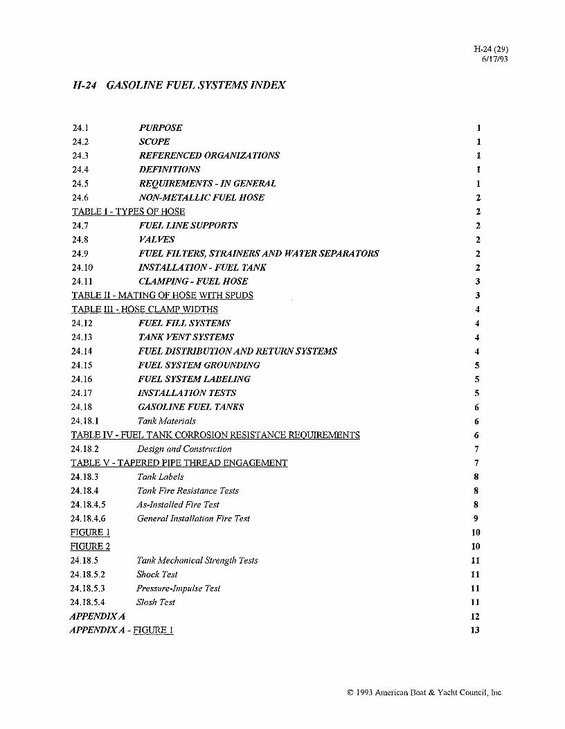
H-24 GASOLINE FUEL SYSTEMS INDEX
24.1
24.2
24.3
24.4
24.5
PURPOSE
SCOPE
REFERENCED ORGANIZATIONS
DEFINITIONS
REQUIREMENTS - IN GENERAL
24.6 NON-METALLIC FUEL HOSE
TABLE I - TYPES OF HOSE
24.7
24.8
24.9
24.10
24.11
FUEL LINE SUPPORTS
VALVES
FUEL FILTERS, STRAINERS AND WATER SEPARATORS
INSTALLATION - FUEL TANK
CLAMPING - FUEL HOSE
TABLE II - MATING OF HOSE WITH SPUDS
TABLE III - HOSE CLAMP WIDTHS
24.12
24.13
24.14
24.15
24.16
24.17
24.18
FUEL FILL SYSTEMS
TANK VENT SYSTEMS
FUEL DISTRIBUTION AND RETURN SYSTEMS
FUEL SYSTEM GROUNDING
FUEL SYSTEM LABELING
INSTALLATION TESTS
GASOLINE FUEL TANKS
24.18.1 Tank Materials
TABLE IV - FUEL TANK CORROSION RESISTANCE REQUIREMENTS
24.18.2 DeSign and Construction
TABLE V - TAPERED PIPE THREAD ENGAGEMENT
24.18.3 Tank Labels
24.18.4
24.18.4.5
24.18.4.6
FIGURE 1
FIGURE 2
24.18.5
24.18.5.2
24.18.5.3
24.18.5.4
Tank Fire Resistance Tests
As-Installed Fire Test
General Installation Fire Test
Tank Mechanical Strength Tests
Shock Test
Pressure-Impulse Test
Slosh Test
APPENDIXA
APPENDIX A - FIGURE 1
H-24 (29) 6/17/9.3
1
1
1
1
1
2
2
2
2
2
2
3
3
4
4
4
4
5
5
5
6
6
6
7
7
8
8
8
9
10
10
11
11
11
11
12 13
© 1993 American Boat & Yacht Council, Inc.

( \
I
I
(

H-24 GASOLINE FUEL SYSTEMS
Based on ABYC's assessment of the state of existing technology and the problems associated with achieving the requirements of this standard, ABYC recommends compliance with this standard by August 1, 1994.
24.1 PURPOSE
These voluntary teclmical practices and engineering standards establish requirements for the design, choice of materials for, construction and installation of permanently installed gasoline fuel systems.
24.2 SCOPE
ll1ese voluntary teclmical practices and engineering -standards apply to all parts of permanently installed gasoline fuel systems from the fuel fill opening to the point of connection with the propulsion engine and/or any auxiliary equipment contained on inboard and outboard powered boats.
24.3 REFERENCED ORGANIZATIONS
ABYC - American Boat & Yacht Council, Inc. 3069 Solomon's Island Road, Edgewater,:MD 21037. (410)956-1050.
ASTM - American Society for Testing and Materials, 1916 Race Street, Philadelphia, PA 19103. (215)299-5400.
Military Specifications - Military specifications may be obtained from the Naval Publications and Forms Center, 5801 Tabor Avenue, Philadelphia, PA 19120.
SAE Society of Automotive Engineers, 4000 COI1ill1onwealth Drive, Warrendale, PA 15096. (412)776-4841.
UL - Underwriters Laboratories, Inc., 12 Laboratory Drive, PO Box 13995, Research Triangle Park, NC 27709. (919)549-1565.
24.4 DEFINITIONS
Accessible - Capable of being reached for inspection, removal or maintenance without removal of permanent boat structure.
Anti-Siphon Valve - A valve which must be opened by fuel pump suction to withdraw fuel from the tank and which will remain closed without fuel pump suction, preventing siphon action created by a break at any point in the fuel feed system.
Fuel Filter - A filtering device with a micron rating less than 500.
H-24 (29) 6/17/93
Fuel Strainer/Rock Screen - A screening device to remove coarse debris from the fuel supply and still permit the passage of water.
Gasoline - "Gasoline" includes all gasoline based fuels. The Federal Hazardous Substance Act classifies gasoline as "extremely flanmmble" having a flash point at, or below, _7°C (20°F).
Pemwnent!y Installed - Securely fastened so that tools such as wrenches and screwdrivers must be used for removal.
Readily Accessible - Capable of being reached quickly and safely for effective use under emergency conditions without the use of tools.
Static Floating Position - The attitude in which a boat floats in calm water, with each fuel tank filled to its rated capacity, but with no person or item of portable equipment on board. Other tanks such as water, holding and live bait well tanks are to be empty. Factory supplied pennanently attached non-portable equipment is to be on board the boat.
Water Separator - A device to separate water from the fueL
24.5 REQUIREMENTS - IN GENERAL
24.5.1 Fuel systems shall be liquid and vapor tight to the hull interior.
EXCEPTIONS: 1. Permeatioll of Itoses witltill tlte limits of SAE JJ 527 DEC85.
2. Permeatioll of fuel tallks witltill tlte limits of CFR 183 Subpart K (183.620, (a), (5), (i).
24.5.2 Fuel systems shall be designed to operate within an ambient temperature range from -29°C (-20°F) to 80°C (l76°F) without failure or leakage.
24.5.3 Valves or petcocks for drawing fuel from the system shall not be installed (see H-24.9.3).
24.5.4 Metals and metal alloys used in a fuel system shall be selected to minimize galvanic action.
24.5.5 Gaskets and joint sealers shall be designed to withstand exposure to ASTM Reference Fuel C for 30 days, at which time there shall be no leakage when subjected to the fuel system pressure in accordance with ABYC H-24.17.4 for 24 hours.
© 1993 American Boat & Yacht Council, Inc. I
H-24 (29) 6/17/93
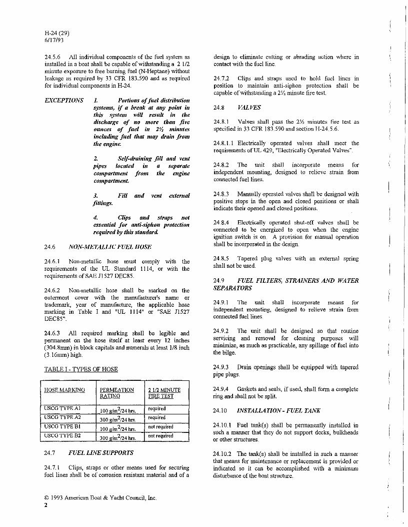
24.5.6 All individual components of the fuel system as installed in a boat shall be capable of withstanding a 2 1/2 minute exposure to free burning fuel (N-Heptane) without leakage as required by 33 CFR 183.590 and as required for individual components in H-24.
EXCEPTIONS 1. Portiolls of fi,el distributioll systellls, if a break at alty poillt itt tlris system will result itt tlte discharge of 110 more tlrall five Ollllces of fuel ill 2YJ lIIilllltes illciudillg filel tlrat lIIay draill frolll tlte ellgille.
2. Selj-draillittg fill alld vellt pipes located itt a separate compartmellt from tl'e ellgille COlllpartmellt.
3. Fill alld vellt extemal fittillgs.
4. Clips attd straps Iwt esselltial for allti-sipltoll protectioll required by tltis stalldard
24.6 NON-METALLIC FUEL HOSE
24.6.1 Non-metallic hose must comply with the requirements of the UL Standard 1114, or with the requirements ofSAE Jl527 DEC8S.
24.6.2 Non-metallic hose shall be marked on the outermost cover with the manufacturer's name or trademark, year of manufacture, the applicable hose marking in Table I and "UL 1114" or "SAE Jl527 DEC8S".
24.6.3 All required marking shall be legible and permanent on the hose itself at least every 12 inches (304.8mm) in block capitals and numerals at least 118 inch (3. 16mm) high.
TABLE I - TYPES OF HOSE
HOSE MARKING PERMEATION 2112 MINUTE RATING FIRE TEST
USCG TYPE Al 100 glm2/24 hrs. required
USCGTYPEA2 300 glm2124 hrs. required
USCG TYPE Bl 100 g/m2124 hrs. not required
USCGTYPEB2 300 g/m2124 hrs. not required
24.7 FUEL LINE SUPPORTS
24.7.1 Clips, straps or other means used for securing fuel lines shall be of cOITosion resistant material and of a
© 1993 American Boat & Yacht Council, Inc. 2
design to eliminate cutting or abrading action where in contact with the fuel line.
24.7.2 Clips and straps used to hold fuel lines in position to maintain anti-siphon protection shall be capable of withstanding a 2\1, minute fire test.
24.8 VALVES
24.8.1 Valves shall pass the 2\1, minutes fire test as specified in 33 CFR 183.590 and section H-24.5.6.
24.8.1.1 Electrically operated valves shall meet the requirements ofUL 429, "Electrically Operated Valves"
24.8.2 The unit shall incorporate means for independent mounting, designed to relieve strain from connected fuel lines.
24.8.3 Manually operated valves shall be designed with positive stops in the open and closed positions or shall indicate their opened and closed positions.
24.8.4 Electrically operated shut-ofT valves shall be connected to be energized to open when the engine ignition switch is on. A provision for manual operation shall be incorporated in the design.
24.8.5 Tapered plug valves with an external spring shall not be used.
24.9 FUEL FILTERS, STRAINERS AND WATER SEPARATORS
24.9.1 The unit shall incorporate means for independent mounting, designed to relieve strain from connected fuel lines.
24.9.2 The unit shall be designed so that routine servicing and removal for cleaning purposes will minimize, as much as practicable, any spillage of fuel into the bilge.
24.9.3 Drain openings shall be equipped with tapered pipe plugs.
24.9.4 Gaskets and seals, if used, shall form a complete ring and shall not be split.
24.10 INSTALLATION - FUEL TANK
24.10.1 Fuel tank(s) shall be permanently installed in such a manner that they do not support decks, bulkheads or other structures.
24.10.2 The tank(s) shall be installed in such a manner that means for maintenance or replacement is provided or indicated so it can be accomplished with a minimunl disturbance of the boat structure.

24.10.3 Tank connections and fittings must be accessible.
24.lOA Tank labels must be accessible and visible to the unaided eye.
24. m5 Fuel tanks shall be installed and restrained so that the fuel tank does not move at the mounting surface more than 114"
EXCEPTION: Space required for expallsioll due to permeatioll of II ell' 1I01l-metallic fllel tallks.
24 .. 10.6 All non-integral tank supports, chocks or hangers shall be separated from the tank surface by a non-metallic non-moisture-absorbent, non-abrasive material suitable for the purpose (e.g .. neoprene, Teflon and high density plastics).
24.10.6.1 Self-wicking material, such as carpet pile, shall not be in contact with the tank.
24.10.7 Metallic fuel tanks installed above flat surfaces shall be separated from the surfaces by at least 114" air space when filled with fuel.
24.10.8 Each metallic tank must be installed to allow drainage of accumulated water from the tank's surfaces when the boat is in its static floating position.
24.10.9 Metal tanks shall be installed where they cannot be reached by normal accumulation of bilge water in the static floating position.
24.10.10 Aluminized steel tanks of less than .0785" (2mm) thickness shall be installed above the cockpit floors or above deck if there is not a clearly defined cockpit
24.10.11 If a metallic fuel tank is encased in plastic, the tank material may not be a ferrous alloy, the plastic must be attached to the metal surface of the tank so as to prevent moisture between the metal and the plastic, the adhesive strength of the metal to plastic bond must exceed the cohesive strength of the plastic, the fuel tank must be supported in the boat by means other than plastic foam.
24.10.12 Cellular plastic used to encase fuel tanks must:
24.10.12.1 not change volume by more than 5 percent or dissolve after being immersed in any of the following liquids for 24 hours at 29°C (84.2°F):
" Reference Fuel B of ASTM D-471, dated December 18, 1968. " No.2 Reference Oil of ASTM D-471, dated December 18, 1968. " Five percent solution of trisodium phosphate in water.
H-24 (29) 6/17/93
24.10.12.2 not absorb more than 0.12 pound of water per square foot of cut surface measured under Military Specification MIL P-21929B, dated June 22, 1970.
24.10.13 Non-polyurethane cellular plastic, if used to encase fuel tanks, must have a compressive strength of at least 60 pounds per square inch at 10 percent deflection, measured under ASTM D-1622, "Apparent Density of Rigid Cellular Plastics", dated September 30, 1963.
24.10.14 Polyurethane cellular plastic, if used to encase fuel tanks, must have a density of at least 2.0 pounds per cubic foot, measured under ASTM D-1622, "Apparent Density of Rigid Cellular Plastics", dated September 30, 1963.
24.10.15 Non-metallic fuel tanks encased in plastic foam which does not meet the requirements of H-24. 10 .. I I shall be restrained by other means in addition to the plastic foam.
24.10.16 A means to determine fuel level or quantity shall be provided.
24.11 CLAMPING - FUEL HOSE
24.11.1 Flexible hose not equipped with pennanent1y attached end fittings such as swaged sleeve and threaded insert shall be attached with corrosion resistant metallic clamps.
24.11.2 The ID of a hose and the OD of a cOlU1ecting spud or fitting must meet the specification in Table PI II.
TABLE II - MATING OF HOSE WITH SPUDS
MAXIMUM DIFFERENCE IF MINOR OD IS: IN DIAMETER IS:
Inches (Millimeters) Inches (Millimeters) Less than 3/8 (9.53) 0.020 ( .508)
3/8 (9.53) thru 1 (25.4) 0.035 ( .889) Greater than 1 (25.4) 0.065 (1.651)
24.11.3 Hose shall not be installed of helical threading or knurling that provides a path for fuel leakage
24.11.4 Clamps depending solely on the spring tension of the metal shall not be used.
24.11,5 Clamps shall be installed to impinge directly on the hose and shall not overlap each other.
24.11.6 Clamps shall be beyond the flare or bead, or fully on serrations where provided, and at least 114 inch (6mm) from the end ofthe hose
© 1993 American Boat & Yacht Council, Inc 3
H-24 (29) 6117/93
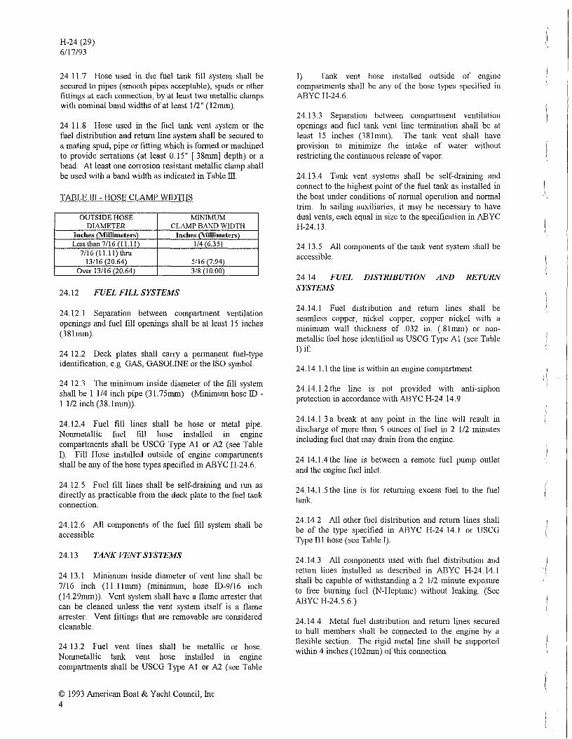
24.11.7 Hose used in the fuel tank fill system shall be secured to pipes (smooth pipes acceptable), spuds or other fittings at each cOlmection, by at least two metallic clamps with nominal band widths of at least 112" (12mm).
24.1 L8 Hose used in the fuel tank vent system or the fuel distribution and return line system shall be secured to a mating spud, pipe or titting which is formed or machined to provide sen-at ions (at least 0.15" [.38mm] depth) or a bead.. At least one con-osion resistant metallic clamp shall be used with a band width as indicated in Table III
TABLE III - HOSE CLAMP WIDTHS
OUTSIDE HOSE MINIMUM DIAMETER CLAMP BAND WIDTH
InchesO\1illlIneters) Inches(~illlIneters)
Less than 7/16 (1 LIl) 114 (635) 7/16 (1 U I) thru
13/16 (20.64) 5/16 (7.94) Over 13/16 (20.64) .. 3/8 (10.00)
24..l2 FUEL FILL SYSTEMS
24.12.1 Separation between compartment ventilation openings and fuel fill openings shall be at least 15 inches (38Inun).
24.12.2 Deck plates shall carry a permanent fhel-type identification, e.g. GAS, GASOLINE or the ISO symbol.
24 . .12.3 The minimum inside diameter ofthe till system shall be I 114 inch pipe (3 L75mm). (Minimum hose ID -1 1/2 inch (38.1mm)).
24.12.4 Fuel fill lines shall be hose or metal pipe. Nonmetallic fuel fill hose installed in engine compartments shall be USCG Type Al or A2 (see Table I). Fill Hose installed outside of engine compartments shall be any of the hose types specified in ABYC H·24.6.
24.12.5 Fuel till lines shall be self-draining and run as directly as practicable from the deck plate to the fuel tank cOlmection.
24.12.6 All components of the thel fill system shall be accessible
24.13 TANK VENT SYSTEMS
24.13. I Minimum inside diameter of vent line shall be 7116 inch (11 Ilmm) (minimum, hose ID-9/16 inch (14.29mm)). Vent system shall have a flame arrester that can be cleaned unless the vent system itself is a flame arrester. Vent fittings that are removable are considered cleanable.
24.13.2 Fuel vent lines shall be metallic or hose. NOlunetallic tank vent hose installed in engine compartments shall be USCG Type Al or A2 (see Table
© 1993 American Boat & Yacht Council, Inc. 4
I) Tank vent hose installed outside of cnginc compartments shall be any of the hose types specified in ABYC H-24.6
24.13.3 Separation between compartment ventilation openings and fuel tank vent line termination shall be at least 15 inches (38Inun). The tank vent shall have provision to minimize the intake of water without restricting the continuous release of vapor.
24.13.4 Tank vent systems shall be self-draining and COl1l1ect to the highest point of the ftlel tank as installed in the boat under conditions of normal operation and normal trim. In sailing auxiliaries, it may be necessary to have dual vents, each equal in size to the specification in ABYC H-24.13.
24.13.5 All components of the tank vent system shall be accessible.
24.14 FUEL DISTRIBU110N AND RETURN SYSTEMS
24.14. I Fuel distribution and return lines shall be seamless copper, nickel copper, copper nickel with a minimum wall thickness of .032 in. (.8Inun) or nonmetallic fuel hose identified as USCG Type Al (see Table I) if'
24.14. \.I the line is within an engine compartment
24.14. L2 the line is not provided with anti-siphon protection in accordance with ABYC H-24.14.9.
24.14.1.3 a break at any point in the line will result in discharge of more than 5 ounces of fhel in 2 1/2 minutes including fuel that may drain from the engine ..
24.14.1.4 the line is between a remote thel pump outlet and the engine fuel inlet
24.14.1.5 the line is for returning excess thel to the fuel tank.
24.14.2 All other fuel distribution and return lines shall be of the type specified in ABYC H-24.14. I or USCG Type B I hose (see Table I).
24.14.3 All components used with fuel distribution and return lines installed as described in ABYC H-24. 14. I shall be capable of withstanding a 2 112 minute exposure to free burning ftlel (N-Heptane) without leaking. (See ABYC H-24.5.6 .. )
24.14.4 Metal thel distribution and return lines secured to hull members shall be cOlmected to the engine by a tlexible section. The rigid metal line shall be supported within 4 inches (102nun) ofthis cOlmection.
\ \

24.145 Fuel systems shall be equipped with an independently supported fuel strainer complying with ABYC H-24.18.2 10, if a strainer is not incorporated in the pickup tube.
24.14.6 Fuel filters shall be independently supported on the engine or boat stmcture.
2414.7 Electrically operated fuel pump systems shall be cOlmected to be energized only when the engine ignition switch is on and the engine is mnning. A momentary type override is acceptable for starting. Electric fuel pumps, if used, shall be independently supported and located within 12 inches (305mm) of the engine. The outlet pressure of electrically operated fuel pumps shall be rated or controlled to the maximum carburetor fuel inlet pressure specified by the engine manufacturer.
EXCEPTION: Electric fllel pUllipS usell to tral/sfer fllel betweell tanks.
24.14.8 On vessels with electronic fuel injection systems requiring that unused fuel be retumed to the fuel tank and installed in systems with multiple fuel tanks, provisions shall be made for simultaneous switching of the fuel draw and retum lines
24.14.9 Fuel distribution and retum systems shall be provided with anti-siphon protection by at least one of the following:
24.14.9.1 Keeping all parts of fuel distribution and retum lines above the level of the tank top from the tank to the carburetor inlet or a location where fuel leakage cannot enter the boat when the boat is in its static floating position.
2414.9.2 Installing an anti-siphon device at the tank withdrawal fitting or along the line, with a rated siphon protection head and flow rate greater than required for the installation
24..l4.9.3 Installing an electrically operated valve at the tank withdrawal fitting or along the line connected to be energized open only when the engine ignition switch is on and the engine is numing A momentary type override is acceptable for starting
24.14.94 Installing a manual shut-off valve directly at the fuel tank cOlmection arranged to be readily accessible for operation from outside the compartment if the fuel tank top is located below the level of the carburetor inlet and the fuel line is rigid metal or USCG Type Al hose. If the length of fuel line from the tank outlet to the engine inlet is greater than 12 feet, a second manual shut-olT valve shall be installed at the fuel inlet cOlmection to the engine.
NOTE: "Readily accessible frolll olltside tlte compartmellt" il/cllldes a sltllt-off valve imtalled at tlte
1-1-24 (29) 611 7/93
tmlk close to alld directly below all access port ill tlte deck tltrough which the valve call be operated
24.14.10 Quick discOlmect fittings used between fuel distribution and retum lines and outboard motors shall automatically shut off fuel flow when discOlmected.
24.14.11 Fuel distribution and retum lines provided with anti-siphon protection shall be installed in outboard powered boats equipped with permanent tanks, which shall terminate at a fitting at the stem where spillage will not enter the boat
24.14.1 Ll TIle stem fitting is not required if antisiphon protection is provided by an anti-siphon or electrically operated valve at the tank
24.1411.2 Fuel distribution and retum lines and stem fittings need not be installed if fuel tanks with withdrawal fittings near the stem are provided with anti-siphon or electrically operated valves
24.14.12 All components of the fuel distribution and retum system shall be accessible.
24.15 FUEL SYSTEM GROUNDING
Each metal or metallic plated component of the fuel fill system and fuel tank, which is in contact with the fuel, must be grounded so that its resistance to the boat's ground is less than one olnn. Wire ends shall not be clamped between the fill pipes and hose.
24.16 FUEL SYSTEM LABELING
The following infonnation shall be placed on a permanent label in a readily visible location on the boat or at a point of frequent servicing of the boat
.ill. WARNING LEAKING FUEL IS A FIRE AND EXPLOSION
HAZARD INSPECT SYSTEM AT LEAST ANNUALLY
24.17 INSTALlATION TESTS
24.17.1 There must be no blow back of fuel through the fill fitting when filling at a rate of 9 gpm from 114 to 3/4 of the capacity on the tank labeL For fuel tanks of 25 gallons capacity or less, the fill rate may be reduced to 6 gpm.
NOTE: A test to determille compliallce witlt this requiremellt may be performed 011 a represelltative illstallatioll.
24.17.2 Fuel fills shall be located and oriented so that no fuel can enter the boat when it is in its static floating
© 1993 American Boat & Yacht Council, Inc. 5

H-24 (29) 6/17/93
position and fuel overflows at a rate of 5 gpm for 5 seconds.
24.1 73 Overflow from the fuel tank vent at the rate of 2 gpm or less shall not enter the boat
24 J 7.4 After installation, the fuel system of every boat shall be pressure checked to at least 3 psi or at 1 112 times the maximum hydrostatic head to which it may be subjected in service, whichever is greater.. The fuel system shall evidence no leakage under such testing, checked at a minimum of 5 minutes after application of the test pressure, for systems of 50 or less gallons capacity, with one additional minute for each increment of 10 gallons, or fraction thereof, above 50 gallons. A leak detection method other than the pressure drop method must be used at every joint except at the deck fill and exterior vent fittings.
NOTE: It is suggested tltat soapy test solutiolls be 11011-corrosive alld 1I01l-toxic. Ammonia, which is prese"t ill some soaps and detergellts, creates a cOllditioll which attacks brass fittings like those used ill fuel systems. Undetectable at first, ill a matter of mOlltlts these fittings may develop cracks creating a very hazardous situatioll.
24.18 GASOLINE FUEL TANKS
24.18.1 Tank Materials
24.18.1.1 Material thickness shall be at least the mmlmum thickness listed in Table IV Materials not listed in Table IV shall be tested in accordance with ASTM Bl 17, "Method of SaIt Spray (Fog) Testing", to the extent of demonstrating corrosion resistance equivalency to those materials listed.
24.18.1.2 Fuel tanks shall not be constructed of temeplate steel
24.18.1.3 Non-metallic materials are considered acceptable for corrosion resistance; however, all other requirements of this standard must be met
24.18.1.4 TIle copper-base alloys normally used for fuel fittings and lines are considered acceptable for direct coupling with all filel tank materials listed in Table IV, except aluminum Copper-base alloy components shall be separated from contact with aluminum tanks or fitting plates by means of a galvanic barrier such as 300 series stainless steel or galvanized steel. Fastenings used to couple fittings such as fuel senders to aluminum tanks shall be of 300 series stainless steel or equivalent in corrosion resistance.
TABLE IV - FUEL TANK CORROSION RESISTANCE REOUIREMENTS
,--------MINIMUM NOMINAL
MATERIAL SPECIFICATION SHEET THICKNESS GAUGE WELDING PROCESSES (1)
Nickel-Copper ASTM-BI27 Class A .031 in. (.79mrn) 22 US. std. Resistance Seam, Inert Gas Shielded Arc, Oxv-acetylene
Copper-Nickel ASTM-BI22 .045 in. (1.14mrn) 17 AW.G- Inert Gas Shielded Arc Oxy-acetylene
I-::-Resistance
Copper (2) ASTM-BI52 .057 in. (1.45mrn) 15 AW.G. Inert Gas Shielded Arc Carbon Arc Type E.T.P. --- O~-acet~lene
Copper-Silicon ASTM-B97 .050 in. (I:27mrn) 16 AW.G Inert Gas Shielded Arc Types A, B & G Carbon Arc
Oxy-acetylene Metal-Arc
Steel Sheet (3) ASTM-A93 .. 0747 in. (\.90mrn) 14 Mfrs. Metal-Arc Oxy-acetylene Inert Gas Shielded Arc
1---:-;---Resistance
Aluminized ASTMAA63 .0478 in. (1.2Imrn) 18 Mfrs. Metal-Arc Steel (5) Oxy-acetylene
Inert Gas Shielded Arc Resistance
Aluminum (4) Alloy 5052 or .090 in. (2. 29mrn) ...................... - Inert Gas Shielded Arc 5083 or 5086 Resistance
Stainless Steel (6) 316L .031 in (.79mrn) 22 US. std. Metal-Arc Oxy-acetylene Inert Gas Shielded Arc Resistance --
NOTES: 1. Tallk seams produced by tlte weldillg processes listed shall be ductile alld lIoll-porous.
© 1993 American Boat & Yacht Council, Inc 6

2. Copper tallks shall be illtemally till coated
H-24 (29) 6/17/93
3. Steel Sheet tallks, whell COllstructed for gasolille, shall be galvallized ills ide alld olltside by the "Itotdip process.
4. Alumillum tallkflttit,g plates sit all be made of 5052,5083,5086, 6061 or 6063 Alumillum or 300 series Stailliess Steel
5. Alumillized Steel tallks shall have a corrosioll illhibitillg baked paillt or equivalent coatillg 1I0t less thall.0015 itl. (.0381mm) tlticklless applied to the total tallk exterior.
6. Stailliess Steel tallks shall be cylimirical witlt domed heads alld a capacity of less tltall 20 gallolls.
24.182 Design and Construction
24.18.2.1 hull.
Fuel tanks shall not be integral with the
24.18.2.2 Each opening into the fuel tank must be at or above the topmost surface of the tank.
24.182.3 The tank design shall be such that no exterior metallic part of the tank will trap water as the tank is intended to be installed when the boat is in the static floating position
24.18.2.4 Tank bottoms shall have no pockets that will accumulate water or sediment
24.18.2.5 The exterior shape of the tanks shall provide smooth bearing surfaces to support and secure the tank.
24.18.2.6 Spuds and other tank fittings shall hi.' attached so as to maintain the liquid and vapor tight integrity of the tank without reducing the strength of the tank walL
24.18.2.7 If barnes are provided, the total open area provided in the barnes shall be a maximum of 30 percent of the tank cross section in the plane of the barne. Barne openings shall be designed so that they do not prevent the fuel flow across the bottom or trap vapor across the top of the tank.
24.18.2.8 Threaded connections into fuel tanks shall be in accordance with the American Standard Taper Pipe Thread (NPTF) and shall provide for thread engagement in accordance with Table V.
TABLE V - TAPERED PIPE THREAD ENGAGEMENT
NOMINAL PIPE SIZE MINIMUM THREAD ENGAGEMENT
(See NOTE) Inches
'--.
1/8 .162 114 .228 3/8 .240 112 .320 3/4 .339
I .400 I 114 .420 I 112 .420
2 .436
NOTE: The millil1lllm lellgths of thread ellgagemellt are those which call IIormally be achieved by lrami, whell assemblillg a male alld female pipe thread togetlter. Additiollal tightellil/g is lIecessary to make a joiltl wldel, willl/ot leak.
24.18.2.9 Rigid fuel pick-up tubes and fill pipes which extend near the tank bottom shall have clearance to prevent contact with the bottom due to flexing of the tank.
24.18.2.10 If a pick-up tube is equipped with a fuel strainer, it shall:
24.182.10.1 permit water contamination to be withdrawn from the tank with the fuel,
24.18.2.10.2 have a micron rating of 500 minimum, 600 maximum,
24.18.2.10.3 be resistant to salt, water, alcohol and stale gasoline, and
24.18.2. 10.4 be accessible for servicing.
24.18.2.11 If the fuel pick-up tube is not fumished as part of the tank, the tank manufacturer shall provide a detailed construction print of the tank and the pick-up tube installation
© 1993 American Boat & Yacht Council, Inc. 7

H-24 (29) 6/17/93
24 .. 18.2.12 The fuel retum line terminus shall be above the level of the fuel when the tank is filled to its rated capacity.
24.18.2.13 Fuel tanks shall be designed to withstand the applicable tests indicated in H-24.18.4 and H-24.18.5.
NOTE: Fuel tallks meetillg tlte requirements of ANSIIUL 1102 "Noll-integral Marille Fuel Tanks" comply with these requiremellts.
24.18.3 Tank Labels
24.18.1.1 All)uel tanks shall bear a label with at least the following information:
24.18 .. 3.1.1 Manufacturer's name or trademark and address.
24.18.3.1.2 Month (or lot number) and year of manufacture.
24.18.3.13 Capacity in U.S. gallonslliters.
24.18.3.1.4 Material specification and thickness.
24.18.3.1.5 Fuel for which tank is suitable.
24.18.3.1.6 Maximum test pressure ..
24.18.3.1.7 Model designation.
24.18.3.1.8 The statement, "This tank has been tested under 33CFR 183.51O(a).."
24.18.3.2 Each letter and each number on a label must:
24 .. 18.3.2.1 be at least 1116 inch (1.6mm) high, and
24.18.3.2.2 contrast with the basic color of the label or be embossed on the labeL
24.18.13 Each label must
24.18.3.3.1 withstand the combined effects of exposure to water, oil, sea spray, direct sun light, heat, cold and wear expected in normal operation of the boat without loss of legibility; and
24.18.3.3.2 resist efforts to remove or alter the information on the label without leaving some obvious sign of such efforts.
24.18.4 Tank Fire Resistance Tests
24.18.4.1 Representative samples of the fuel tanks shall be subjected to the test described herein. The tank to be tested shall be a complete assembly and include the
© 1993 American Boat & Yacht Council, Inc. S
fuel pick-up tube, fuel-fill pipe and file I gauge specified for the fuel tank.
24.18.4.2 A single file I tank design, shown to be representative of a series of filel tanks of similar design, size and constmction, may be tested as representative of that series of filel tanks.
24.18.4.3 A file I tank shall be capable of withstanding exposure to a test fire without contributing to the fire due to leakage of the fuel contained therein. For the purpose of this test, slight vapor leakage will be permitted except in the tank shell, if it can be shown that the path of leakage will not permit a fire outside the tank to ignite vapors within the tank
24.18.4.4 The filel tank sample to be tested is to be provided with all the attacimlents specified by the manufacturer.
24.18.4.5 As-Installed Fire Test
24.18.4.5.1 This test shall be conducted to qualify fuel tanks intended to be installed in a partiCUlar model boat or series of boats where the constmction of the tank is known and the installation of the tank is specified or otherwise controll ed.
24.18.4.5.2 The fuel tank sample shall be installed in an actual or simulated hull section of sufficient size to simulate fire conditions aboard the boat All bulkheads, supports, floors and other surfaces in the simulated filel tank compartment shall be of the same material or of equivalent flammability to that used on the boat.
24.18.45.3 To qualify a fuel tank intended for use in a series of boats, the fuel tank sample shall be installed in a simulated hull section providing the maximum fire exposure representative ofthat series of boats.
24.18.4.5.4 TIle fuel tank sample and all connecting piping and fittings shall be checked for leakage at an aerostatic pressure of 3 pounds per square inch (psi) applied to the tank vent. Following the pressure test, the pressure shall be released and the tank vent left open to simulate a normal condition The size of the fuel tank sample vent shall be detennined by the size of the vent fittings provided by the manufacturer.
24.18.4.5.5 The fuel tank sample shall be filled to onequarter rated capacity with gasoline and all openings capped or plugged, except for the fuel tank vent which is to be extended without traps, outside the first test area.
24.18.4.5.6 N-Heptane shall be poured into all crevices and liquid traps in which fuel could collect in the boat, assuming a leak anywhere in the fuel system. If possible, the amount of fuel in each liquid trap shall be sufficient to bum for a period of 2 112 minutes
f

24.184.5.7 The test method described in ABYC H-24.184.5 shall be used.
24.1846 General Installation Fire Test
24.184.6.1 This test shall be conducted to qualify fuel tanks where the actual installation conditions are not known.
24.18.4.6.2 The fuel tank sample is to be supported in a test enclosure, as shown by Figure I, if the fuel tank is intended for below-deck installation, or in a test enclosure, as shown in Figure 2, if the tank is intended for abovedeck installation
24.18.4.6.3 The side supports of the fuel tank sample are to be spaced to support the fuel tank ends and at each fuel tank barne, and are to be fonned to maintain the fuel tank sample 2 inches (50.8mrn) away from the inside surface of the simulated hull side paneL
24.184.64 The supports for the bottom of the fuel tank sample are to be located in the same maimer as the side supports and are to be fonned to maintain the fuel tank sample .3 inches (76.2nun) above the inside surface of the enclosure
24.18.4.6.5 The fuel tank sample is to be secured to the test enclosure by steel straps. The top of the test enclosure shall be fonned so that the maximum fuel tanks sample set-back does not exceed 2 inches (50.8mm) and the clearance between the top of the test enclosure and the top of the fuel tank sample is not less than 7 inches (1 77.8mrn) nor more than 34 inches (863.6nun).
24.184.6.6 The area of the enclosure beneath the fuel tank sample is to serve as the fuel reservoir and shall be fomled so that the surface of the test fuel extends 6 inches (1 524nun) beyond the fuel tank sample ends and 2 inches (50.8mrn) beyond the exposed front surface of the fuel tank sample. TIle reservoir shall be made leak proof and shall be capable of containing sufficient fuel to bum for a period of 2 112 minutes.
24.18.4.6.7 TIle fuel tank sample and all connecting piping and fittings shall be checked for leakage and .3 psi aerostatic pressure applied to the tank vent Following the Pressure Test, the pressure shall be released and the tank vent left open to simulate a nonnal condition. The size of the fuel tank sample vent shall be detennined by the size of the vent fitting provided by the manufacturer.
24.18.4.6.8 The fuel tank sample is to be filled to onequarter rated capacity with gasoline and all openings capped or plugged, except for the fuel tank vent which is to be extended without traps, outside the Fire Test areas.
24.18.4.6.9 N-Heptane shall be poured into the reservoir in accordance with ABYC H-24.184.5.6.
H-24 (29) 6117/9.3
24.18.4.6.10 TIle test method described in ABYC H-24. I 8.4.5 shall be used.
24 .. 184.7 Test Method for Fuel Tank Fire Test
24.18.4. 7.1 The area in which the test is to be conducted is to be free from drafts but shall have provision for a free inflow of air during the test The test shall be conducted as in ABYC H-24.18.4.7.2, ABYC H-24.18.4.7.3 and ABYC H-24.184.74 below.
24.18.4. 7.2 The N-Heptane in the huH section or the test enclosure shall be ignited and permitted to burn for a continuous period of2Y, minutes. The temperature within one inch of the component must be at least 648°C (l200°F) some time within the 2Y, minute test.
24.18.4. 7.3 At the end of the 2 Y, minute test period, any continued burning is to be extinguished.
24.18.4.74 Following the test, the fuel tank sample shall be examined for leakage and then drained and pressure-checked with 114 psi of aerostatic pressure. This pressure shall be applied gradually by means of a suitable regulator so as not to strain the tank due to pressure surge. The tank fails the test if leakage is detected in the tank shell using a means other than the pressure drop method.
© 1993 American Boat & Yacht Council, Inc 9

H-24 (29) 6/17/93
FIGURE 1 ENCLOSURE - BELOW DECK INSTALLATION
H !_! 1_ L_---.--r
FUEL T ANf
TE'3T FUEL -----,"
FIGURE 2 ENCLOSURE - ABOVE DECK INSTALLATION
[I
© 1993 American Boat & Yacht Council, Inc, 10

24.18.5 Tank Mechanical Strength Tests
24.18S I Representative samples of the fuel tanks shall be tested by the tank manufacturer at I 112 times the maximum test pressure indicated on the tank label (see ABYC H-24.18.3), with gauge or sending unit installed. The fuel tank shall not exhibit any leakage.
24.18S2 Shock Test - Representative samples for fuel tanks of less than 25 gallons capacity shall not leak or show signs of permanent deformation or other signs of permanent deformation or other signs of failure following 1000 cycles of vertical shocks with an acceleration of 25g with a duration measured at the base of the shock envelope of 6-14 milliseconds
24.18S2.1 Shock tests for non-metallic fuel tanks shall be conducted on the fuel tank samples which have contained ASTM Reference Fuel C for 30 days at room temperature 21.1 °C - 26.7°C (70°F - 80°F).
24.18.5.2.2 The fuel tank sample filled to capacity with water shall be mounted to a platform using supports, chocks or hangers either fumished with the tank or intended to be used in a boat installation.
24.18. 5.2. 3 The platform shall be connected to a device that will repeatedly raise and drop the platfonll at a rate not to exceed 80 impacts per minute. By varying the height of the drop and/or cushioning under the platform the top surface of the platfonll shall be calibrated as close to the tank center of gravity as is practicable to provide the specified shock impacts.
24.18.5.3 Pressure-Impulse Test - Representative samples of 25 gallons capacity and more shaH not leak or show signs of permanent defonllation or other signs of failure following 25,000 cycles of pressure-impulse.
24.1853. I Pressure-Impulse tests for non-metallic fuel tanks shall be conducted on the fuel tank samples which have contained ASTM Reference Fuel C for 30 days at room temperature 21.1 °C .. 26.7°C (70°F - 80°F).
24.18.5.3.2 The fuel tank sample filled to capacity with water shall be mounted using support, chocks or hangers either fumished with the tank or intended to be used in a boat installation
24.18.5.33 The fuel tank sample is to be attached to a regulated source of pressure of either air, nitrogen or water. The control mechanism of the pressure source is then to be set to cause the pressure in the sample, measured at its top-most surface, to vary from 0 to 3 to 0 psig at a rate of not more than 15 cycles per minute.
24.18.5.4 Slosh Test - Representative samples of fuel tanks of 200 gallon capacity and more shall not leak or show signs of penllanent defonllation or other signs of
11-24 (29) 6/17/93
failure following 500,000 cycles of rocking motion This test shall be performed following the Pressure Impulse Test on the same fuel tank sample
24.18.5.4.1 Slosh tests for non-metallic fuel tanks shall be conducted on the fuel tank samples which have contained ASTM Reference Fuel C for 30 days at room temperature 21 1°C - 26.7°C (70°F - 80°F).
24.18.5.4.2 The fuel tank sample used for this test is to be provided with all attachments specified by the manufacturer.
24.18.5.43 The fuel tank sample is to be centered on a rocker assembly to simulate the recommended tank installation using supports, chocks or hangers either fumished with the tank or intended to be used in a boat installation.
24.18.5.4.4 TIle fuel tank sample is to be filled with dye-colored water to one-half its rated capacity, and all fuel tank fittings, except the tank vent, are to be capped.
2418.5.4.5 The rocker assembly shall be adjusted to produce a rocking motion of approximately 15 degrees to either side of a vertical reference line at a rate of 3 to 4 seconds per cycle.
24.18.5.4.6 The axis of rotation of the rocker and fuel tank sample shall be parallel to the tank barnes and perpendicular to the centerline of the tank length at a level not more than 6 inches (l52.4mm) above or below the tank bottom.
24.18.5.5 Tank Pressure Tests - Every tank shall be tested by its manufacturer prior to installation to the maximum test pressure indicated on the tank label without evidence of leakage. The test pressure shall be not less than 3 psi.
Appendix to follow
© 1993 American Boat & Yacht Council, Inc. 11

H-24 (29) 6117/93
APPENDIX A - MARINE FUEL SYSTEM COMPONENT FIRE TEST
Ap"1 Method
Ap" I "I Conduct the test in a fire test chamber in a draft-free area
Ap" 1"2 Connect the sample into a system of full size fuel piping, complete with a fuel supply tank and the valves, as shown in Figure L
Ap" 13 Center and position the sample vertically nine inches above the liquid surface of a pan of sufficient size both to extend beyond the entire horizontal area of the sample and to accommodate enough N-heptane to burn continuously for at least 2·112 minutes""
Ap.l.4 Charge the tank and the remainder of the system with N-heptane"
Ap.I.5 Position two thennocouples in the sanle horizontal plane as the sample, one-half inch away from the sample surface, and the tips of the thennocouples should be positioned one inch from the end of each fitting of the sample and ten inches above the surface of the fuel level.
Ap" 1.6 l11e supply tank valve will then be opened and the system bled of all air by allowing fuel to flow through the system from the tank through the open discharge valve.
Ap. L 7 With the system full of fuel, shut off the discharge valve" Ignite the pan of fuel and allow it to bum for 2-112 minutes.
Ap.1.8 During the burning, record temperatures at intervals not to exceed IS seconds"
NOTES: If the temperatures measured by olle or both thermocouples do 1I0t reach 648°C at some time durillg tlte 2-112 minute time period, tltell the test shall be repeated witlt a new sample.
Ap.l. 9 At the end of the 2-112 minutes, extinguish the fire by fully discharging a ten pound carbon dioxide extinguisher.
Ap" L 9" I The fuel lines and the sample shall not be disturbed"
Ap" I" I 0 Immediately after the fire is extinguished, the discharge valve shall be opened and fuel allowed to run through the system until a steady stream is obtained.
Ap" 1.11 Then close the discharge valve, place the system under a hydrostatic pressure of three feet of head, and monitor the sample for leakage for a period of five minutes.
© 1993 American Boat & Yacht Council, I11C. 12
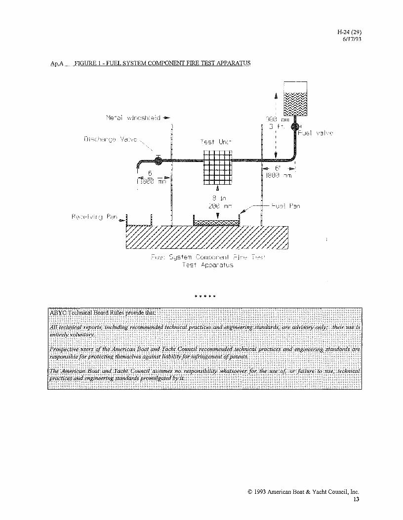
Ap.A FIGURE 1 - FUEL SYSTEM COMPONENT FIRE TEST APPARATUS
~1etal windshield-
Disc Valve
Recei vinr:;1 Pan --
6' i1800 mrh
Test Unit
:3 in 2210 mm
Fue' S~stem Component Fire Test Test Appal-atu5
* * * * *
'~1012J mm 3 ft
6' _.I
1800 mm
Fuel valve
Fuel Pan
H-24 (29) 6/17/93
© 1993 American Boat & Yacht Council, Inc. 13

I
\ ,
j