ABSTRACT Title of Thesis : SUSTAINABILITY THROUGH ...
86
ABSTRACT In a period when it is becoming more and more apparent how we, as humans, have been negatively impacting our planet, it is important for us, as designers, to take a step back and evaluate how new methods of sustainable design can be incorporated into the existing built environment to leave a positive impression on our climate. We have discussed sustainability through design, building typologies, construction materials, and building systems but we can also explore the sustainable method of reusing the existing built environment. This thesis explores how adaptively reusing existing buildings can be a sustainable source of architecture. Buildings that have fallen into neglect and/or ruin can be revitalized through the construction method of mass timber to produce less greenhouse gas emissions during the structure’s life cycle while leaving a larger, healthier impact on our climate. This thesis explores the benefits of mass timber as a sustainable construction method and demonstrates how mass timber can be used as an alternative to steel Title of Thesis: SUSTAINABILITY THROUGH ADAPTATION: REIMAGINING EXISTING SPACES WITH MASS TIMBER CONSTRUCTION Amber N. Robbs, Master of Architecture and Certificate in Historic Preservation, Spring 2020 Thesis Directed By: Professor Brian Kelly, School of Architecture, Planning, & Preservation
Transcript of ABSTRACT Title of Thesis : SUSTAINABILITY THROUGH ...
ABSTRACT
In a period when it is becoming more and more apparent how we, as humans,
have been negatively impacting our planet, it is important for us, as designers, to take
a step back and evaluate how new methods of sustainable design can be incorporated
into the existing built environment to leave a positive impression on our climate. We
have discussed sustainability through design, building typologies, construction
materials, and building systems but we can also explore the sustainable method of
reusing the existing built environment. This thesis explores how adaptively reusing
existing buildings can be a sustainable source of architecture. Buildings that have
fallen into neglect and/or ruin can be revitalized through the construction method of
mass timber to produce less greenhouse gas emissions during the structure’s life cycle
while leaving a larger, healthier impact on our climate.
This thesis explores the benefits of mass timber as a sustainable construction
method and demonstrates how mass timber can be used as an alternative to steel
Title of Thesis: SUSTAINABILITY THROUGH ADAPTATION: REIMAGINING EXISTING SPACES WITH MASS TIMBER CONSTRUCTION
Amber N. Robbs, Master of Architecture and
Certificate in Historic Preservation, Spring 2020
Thesis Directed By: Professor Brian Kelly, School of Architecture,
Planning, & Preservation

frame construction on the site of a 1919 US Navy industrial building. The existing
masonry and steel-framed structure stands as a neglected building that can be adapted
through sustainable methods. By respecting the structure’s heritage and original
purpose, this thesis proposes a secondary building and revitalization of the existing
structure through reusing existing structures with recycled material, like mass timber.
The thesis looks at opening the site to the evolving community of the
Washington D.C. Navy Yard. Maintaining the site as a community gathering space,
this thesis proposes a food hall program, building off the weekly farmers markets that
take place in the structure’s adjacent plaza, and aims to fill the community's need for
a public civic space in the adjoining community library program. The program of this
thesis aims to draw people in to explore the built environment of alternative and
sustainable construction methods.

SUSTAINABILITY THROUGH ADAPTATION: REIMAGINING EXISTING SPACES WITH MASS TIMBER CONSTRUCTION
Amber Nicole Robbs
Thesis submitted to the Faculty of the Graduate School of the University of Maryland, College Park, in partial fulfillment
of the requirements for the degree of Master of Architecture
2020 Advisory Committee: Brian Kelly, Chair Karl Du Puy, Committee Member Matthew Bell, Committee Member

© Copyright by Amber Nicole Robbs
2020

Dedication
I am dedicating this thesis to my family who has always supported the dream of the
little 10-year-old girl who drafted floor plans of every room in the house in the hopes
of one day going to college to become an architect.
Love,
Me
ii

iii
Table of Contents
Dedication ......................................................................................................... ii
Table of Contents ............................................................................................. iii
Chapter 1 Introduction .......................................................................................1
Chapter 2 Precedent Analysis ............................................................................3
2.1 Butler Square ...........................................................................................3
2.2 URBN Campus ........................................................................................5
2.3 GoSpotCheck Headquarters .....................................................................8
2.4 Quincy Market .........................................................................................9
Chapter 3 Climate Change ............................................................................... 11
3.1 Signs of Climate Change ....................................................................... 11
3.2 Impact of Base Building Construction ...................................................13
3.3 Architecture’s Response .........................................................................16
Chapter 4 Context ............................................................................................18
4.1 Navy Yard History .................................................................................18
4.2 Site History ............................................................................................20
4.3 Site Selection Process ............................................................................24
4.4 Site Analysis...........................................................................................31
Chapter 5 Preservation and Adaptive Reuse Regulations ................................35
5.1 Introduction ............................................................................................35
5.2 Federal Benefits and Regulations ..........................................................36
5.3 District of Columbia and Southeast Federal Center Local Regulations 37
Chapter 6 Mass Timber ....................................................................................40
6.1 Introduction ............................................................................................40
6.2 What is Mass Timer? .............................................................................40
6.3 Sustainable Properties ............................................................................44
Chapter 7 Architecture Intervention .................................................................48
7.1 Program Selection ..................................................................................48
7.2 Urban Historic Layers ............................................................................50

iv
7.3 Design ....................................................................................................54
7.4 Historic References ................................................................................63
7.5 Sustainable Structure and Elements .......................................................65
Chapter 8 Conclusion .......................................................................................67
Bibliography ....................................................................................................70
Figure Reference ..............................................................................................74

Introduction
Page | 1
Chapter 1 Introduction
Recycling has become second nature to most modern communities as we
strive to take care of our environment. We are working to find new ways to reduce,
reuse, and recycle everything from cars to plastic bottles and most importantly,
materials that can be harmful to our planet. Sustainable design has become the goal
for architecture as professionals seek to reduce the negative impact the built
environment can have on our environment. Adaptive reuse can be a sustainable form
of recycling the built environment. The built environment stands as a glimpse into our
past and a physical representation of how we have impacted our environment.
Through adaptive reuse, a structure and/or space can be reimagined and given
a new purpose to add value to the structure’s future. By respecting the structure’s
heritage and original purpose, the existing built environment can become a part of
sustainable construction by reusing existing structures with recycled material, like
mass timber. By reusing the built environment instead of demolishing an existing
structure to build a new building in its place, adaptive reuse can retain the original
building’s embodied energy and negative impacts through sustainable construction
methods and minimal environmental impact while giving the built environment a new
purpose.
This thesis seeks to explore how adaptively reusing existing buildings can be a
sustainable source of architecture. Buildings that have fallen into neglect and/or ruin
can be revitalized through using recycled materials like mass timber to produce less
greenhouse gas emissions during the structure’s life cycle while leaving a larger,
healthier impact on our climate. This thesis will explore the benefits of adaptive reuse

Introduction
Page | 2
and mass timber construction as a sustainable construction method to demonstrate
how mass timber can be used as an alternative to steel frame construction in the built
environment.

Precedent Analysis
Page | 3
Chapter 2 Precedent Analysis
2.1 Butler Square
Built in 1908, this warehouse
was the largest wholesale warehouse
of its time west of Chicago. Butler
Square was designed by local
Minneapolis architect Harry Wild
Jones. The nine-story tall timber
structure provided five hundred
thousand square feet of warehouse and distribution space due to its heavy timber
construction. The heavy timber posts and beams came from the contractor’s, T.B.
Walker, own Douglas fir tree farm and lumber mill just one hundred and twenty-five
miles away in Aitkin, Minnesota1. The columns were precut and put together on a
module measuring 14’ by 16’. The Douglas columns started at 24” wide and
gradually diminished to 9” by the top level. The structure was also supported by 3’
thick masonry firewalls throughout the building.
In 1971 Butler Square was
placed on the National Register of
Historic Places for its significant
example of Chicago School design and
as an example of early 1900s
1 Think Wood. n.d. Butler Square. Accessed November 12, 2019.
Figure 1: Historic Image of Butler Square from the local newspaper (Source: https://www.butlersquare.com/photos)
Figure 2: Heavy timber atrium (Source: Jenna Bauer via Thinkwood.com)

Precedent Analysis
Page | 4
warehouse/office buildings in
Minnesota2. Just four years later,
developer Charles Coyer and Miller
Hanson Westerback Bell Architects
set out to restore life to the aging
warehouse by turning it into a
mixed-use office-retail complex.
This renovation catalyzed preservation, restoration, and adaptive reuse projects within
the Minneapolis Warehouse District.
Because the building was built as a warehouse there was minimal access to
natural daylighting. The 1974 renovation created a central atrium to bring in natural
light so that the exterior of the building could be preserved while still bringing in the
needed natural lighting for office and
retail space. During the 1974 renovations,
the floors were raised to preserve the
natural wood ceilings of the existing
structure using an early version of Nail-
Laminated Timber, a mass timber
product. Today, the building is a mix of
the original historic heavy timber post-
and-beam construction and modern mass
timber construction. Butler Square was
2 Butler Square | Minneapolis Office Space. n.d. Butler Square. Accessed November 12, 2019.
Figure 3: Exterior view of Butler Square today (Source: https://www.butlersquare.com/photos)
Figure 4: Natural daylighting from atrium (Source Pete Sieger via Flickr.com)

Precedent Analysis
Page | 5
the first century-old, multi-tenant commercial building in the nation to achieve
LEED-Exiting Building Operations & Maintenance certification (LEED-ED O&M),
the oldest building in the Midwest to achieve LEED certification, and the first
building in Minnesota to achieve LEED-ED O&M3.
Butler Square illustrates how timber construction can be adapted in a
historically significant structure to support a modern use through sustainable design.
Butler Square has been a gateway precedent in the Midwest for revitalizing existing
structures and mass timber construction. Today Butler Square is surrounded by
redeveloped warehouse structures and new mass timber construction. As the 1974
renovations of Butler Square combined the existing heavy timber and masonry
construction with early mass timber products, this thesis can benefit from the
construction techniques of the 1974 renovations and the sustainable practices that
Butler Square has maintained over the years.
2.2 URBN Campus
Originally built
between 1868 and 1939 as
part of Philadelphia’s historic
Navy Yard, the URBN
warehouse campus served as
a series shipbuilding and
repair facilities for the US
3 Think Wood. n.d. Butler Square. Accessed November 12, 2019.
Figure 5: Historic Images of the Philadelphia Navy Yard as a ship building, repair, and scrapping site (Source: MSRDesign)

Precedent Analysis
Page | 6
Navy until the one hundred eighty-
seven building campus was
decommissioned in 19964. Three years
later the decommissioned navy yard
was added to the National Register of
Historic Places. In 2004 a
comprehensive master plan was
developed to turn the former navy yard
into a mixed-use complex that offered
benefits to developers from the Federal Historic Preservation Tax Incentive Program.
Urban Outfitter’s founder, Dick Hayne, was one of the first companies to
consider the site and purchased four buildings, two hundred eighty-five thousand
square feet, to redevelop into the company’s headquarters. The twenty-three months
of design and renovation included building
documentation to gain Federal Historic
Preservation Tax incentives. The architects,
MSRDesign, focused on utilizing the factory
characteristics of the building’s industrial
materiality, open volumes, and access to
natural daylighting to adapt the warehouses
into a multi-phase corporate campus for
4 Igor Fracalossi and MSR Design. 2010. Urban Outfitters Corporate Campus / MSR Design.
ArchDaily. December 1. Accessed November 12, 2019.
Figure 6: Exterior images of URBN campus (Source: top - Lara Swimmer Photography & Bottom - MSR Design)
Figure 7: Interior images of MSR Design's adaptive reuse design (Source: MSR Design)

Precedent Analysis
Page | 7
URBN5. The renovated office spaces stimulate creativity and collaboration among
employees while honoring the existing history of the site.
The URBN campus is a great precedent for this thesis that illustrates how
structures can be transformed from a public, naval industrial use to a community-
based space. The URBN campus was transformed to create a communal office space
that maximizes the building's open spaces, materiality, and natural daylight to inspire
employees throughout their day to day work and promotes productivity and a positive
work environment. MSR Design was able to reimagine a portion of the historic
Philadelphia Navy Yard while embracing the history of the navy yard district and
URBN’s culture. The design of the campus allows the history of the Navy Yard to be
celebrated and honored by layering the old with the new.
5 Igor Fracalossi and MSR Design. 2010. Urban Outfitters Corporate Campus / MSR Design.
ArchDaily. December 1. Accessed November 12, 2019.
Figure 9: Transformation of URBN buildings over the life of the Navy Yard (Source: MSR Design via Arch Daily)
Figure 8: Section throught the URBN campus (Source MSR Design)

Precedent Analysis
Page | 8
2.3 GoSpotCheck Headquarters
Set in the Lower Downtown
(LoDo) district of Denver, the
GoSpotCheck Headquarters sits as a
historic urban infill between two
historic buildings. The building is an
addition to the historic Rocky
Mountain Seed Building that celebrates the historic character of the existing
streetscape through modern construction methods and materials. Tryba Architects was
committed to designing a building that restored an urban gap in the streetscape by
immersing the building into its surroundings. The jewel box façade followed the scale
and proportions of its neighboring buildings to blend seamlessly with one another.
The jewel box design created a gateway like building for the LoDo district that serves
as a lantern, signifying the entrance to the neighborhood from the south and east.
The GoSpotCheck Headquarters also serves as a precedent to this thesis
through its unique steel and glulam structure. The mass timber product serves as
Figure 10: GoSpotCheck Headquarters set within the historic context of LoDo (Source: Tryba Architects)
Figure 11: Elevation diagram illustrating the addition's relationship to the surrounding historic context through scale, proportion, and radiating lines (Source: Tryba Architects)
Precedent Analysis
Page | 9
lateral support to the building’s steel
frame primary structure. The glulam
beams are attached to the steel frame
structure with heavy, steel plate and
bolt connections. By exposing and
using glulam beams and wood decking
within the structure, the architects were
paying homage to the original historic
Rocky Mountain Seed Building, tying
the two structures together.
2.4 Quincy Market
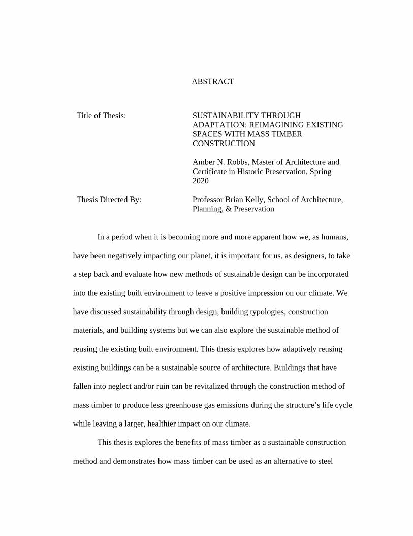
Constructed in 1826, Boston’s Quincy Market
is an extension of historic Faneuil Hall. As the
commercial demand of the market outgrew Faneuil
Hall, Quincy Market was built to meet the demand
for commercial growth. The market hall was
designed with tall floor heights to lead shoppers
down the center hallway, through the long rectangle
pavilion of vendor stalls. In 1966, the whole market complex was designated as a
National Historic Landmark for its historic significance as one of the nation’s largest
market complexes built in the early 1800s.
Quincy Market stands as a programmatic precedent for this thesis to explore
how a historic market hall works and how a market hall can stand as the center of a
Figure 12: Interior image of the steel and glulam structure (Source: Tryba Architects)
Figure 13: Interior of Quincy Hall at opening (Source: Smith, H.G.)

Precedent Analysis
Page | 10
community. Of the six buildings in the
Faneuil Hall market complex, Quincy
market was originally full of grocery
type stalls and has adapted to modern
culture and is now home to many
food-stalls, fast-food style stalls, and
restaurants. Today the market is one of Boston’s most popular tourist destinations and
is also a popular lunch spot of local downtown employees. The surrounding plaza
provides excess vending spaces for stalls that sell snacks and trinkets.
Figure 15: Break down of Quincy Market, South Market, and North Market program types by average square feet, amount, and total square feet (Source: Author)
Figure 14 Activation of plaza space between Quincy Hall and South Market Building (Source: flickr.com)

Climate Change
Page | 11
Chapter 3 Climate Change
3.1 Signs of Climate Change
Homo sapiens have been discovering, adapting, and living off the earth’s
resources since the beginning of our existence. It is becoming clear that the way we
have been using these resources since the beginning of the Industrial Revolution has
been leaving a negative impact on the place we call home. The Industrial Revolution
marked the dramatic increase in industrial activities that our modern civilization
depends upon. These activities have resulted in an increasing concentration of
atmospheric carbon dioxide (CO2). According to the IPCC, 2013: Summary for
Policymakers, the atmospheric concentrations of greenhouse gases have all increased
since 1750. CO2 has increased by 40%, methane (CH4) by 150%, and nitrous oxide
(N2O) by 20% due to human activity.6 Since the mid-1700s these contributing
industrial activities have been growing in popularity as they are perfected and become
6 “IPCC, 2013: Summary for Policymakers.” Accessed October 5, 2018.
Figure 16: Atmospheric CO2 Levels (Source: climate.nasa.gov)
Climate Change
Page | 12
a part of modern society. Around 1950, our use of these activities drastically spiked
and have led to our current unprecedented rate of greenhouse gas emissions.
Throughout Earth’s history, there have been seven known glacial advances
and retreats. The last cycle, the ice age, occurred seven hundred years ago and marked
the beginning of our climate as we know it. According to the findings by NASA, the
current warming cycle is unique to the last seven cycles because 95% of it can be
attributed to human activity since the Industrial Revolution.7 Evidence shows that this
warming will continue to proceed at an unprecedented rate with each passing decade.
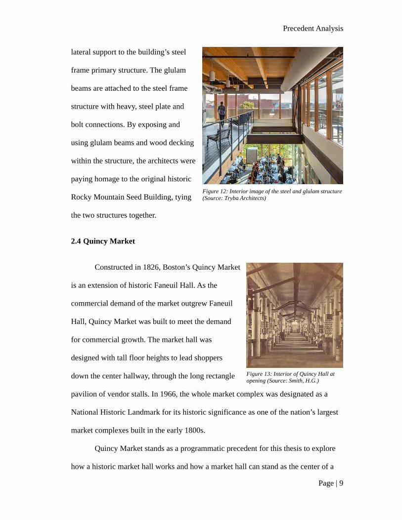
Studies have shown that there is no reason to question that the increased
levels of greenhouse gas emissions are causing the earth to heat up. Physical evidence
of earth warming can be found in the decrease of glaciers mass in the tropical
mountains, Antarctica, and Greenland and the increase in sea levels. More evidence
for climate change
can be found from
ancient history in
tree rings, ocean
sediments, coral
reefs, and the layers
of sedimentary
rocks. The changes
in these natural
forms prove that the
7 “Climate Change Evidence: How Do We Know?” Accessed October 6, 2019.
Figure 17: Top: annual surface temperature change. Bottom: change in average precipitation. (Source: IPCC 2013)

Climate Change
Page | 13
current warming period is occurring at a rate ten times faster than the average post-
ice-age rate8. The sooner we act to reverse the negative impact we have instilled on
our planet, the sooner we can ensure a positive climate for generations to come.
Almost 200 nations adopted the climate agreement at the COP21 (Conference
of the Parties) summit in Paris that aims to limit our planet’s average global
temperature rise to less than two degrees Celsius (3.6 degrees Fahrenheit). By 2050,
the annual CO2 emissions could decrease by 14% to 96% than the emissions recorded
in 19909 if we continue to do our part and take care of our planet. During this period
of climate change, it is important for us, as a species, to realize the impact we have
made and work to make significant changes for the better.
3.2 Impact of Base Building Construction
Climate change is a fundamental part of designing in today’s climate. The
construction of our buildings can negatively impact the environment through
greenfield development,
cement production, and
the burning of fossil
fuels (oil, gas, and coal).
Base building
construction accounts
for almost 40% of
annual energy and raw
8 “Climate Change Evidence: How Do We Know?” Accessed October 6,2019. 9 “IPCC, 2013: Summary for Policymakers.” Accessed October 5, 2018.
Figure 18: Shanghai on its hottest day of recorded history at 105.6℉ (Source: Architect Magazine)

Climate Change
Page | 14
material consumption, 25% of the wood harvest, 16% of freshwater supplies, 44% of
landfills, 45% of CO2 production, and up to 50% of greenhouse emissions from
industrialized countries.10 We, as architects, designers, and creators, can design the
built environment in a way that produces minimal amounts of CO2 and reverse the
negative impact we have instilled in our climate.
The changes in the climate have led to an increase in dramatic natural
disasters, sea-level rise, temperature rising, etc., all things that affect how the built
environment is experienced, used, and built. By 2100 the rising ocean will force as
many as two billion people to migrate further inland and/or to higher ground.11 If CO2
continues to burn at an unprecedented rate and we are not actively working to cut
back on how the built environment is impacting our climate, it could become harder
to build in the first place. If we continue to build the way we are now, the continental
United States will
experience an average
of twenty to thirty more
days above 90 degrees
Fahrenheit annually by
2050.12 Any day above
90 degrees Fahrenheit
can cut into the outdoor
10 Kerr, Warren, ed. 2004. "Adaptive Reuse. Preserving Our Past, Building Our Future."
Accessed October 6, 2019. 11 Cramer, Ned. 2017. "The Climate Is Changing. So Must Architecture." Accessed October
6, 2019. 12 Cramer, Ned. 2017. "The Climate Is Changing. So Must Architecture." Accessed October
6, 2019.
Figure 19: Temperature change in the Continental United States since 1895 to 2018 (Source: The Washington Post)

Climate Change
Page | 15
labor supply by 14%, adding to more construction days, increasing the amount of
CO2 used per project.
In order to make a difference, architects, designers, and creators must find a
way to reduce the use of energy and carbon-intensive technologies that are used daily
in the built environment. Two of the most commonly used building materials are steel
and concrete. Concrete alone attributes to 5% of annual global CO2 emission, with
China producing 3% of the 5%,13 while steel and iron contribute to 3.2% of global
CO2 emission.14 Steel is the newest of these construction materials as it became
popular during the Industrial Revolution for its durability and strength that allows us
to build higher and bigger. As the properties of steel construction proved to be
superior to those of classic wood construction, the negative environmental impact of
construction began to increase
along with the use of steel and
concrete materials. The
manufacturing, transportation,
and installation of steel and
concrete consume a large
amount of energy (embodied
energy) and fossil fuels. Steel
and concrete are not natural
materials and cannot regrow
13 Crow, James Mitchell. 2008. "The Concrete Conundrum." Accessed October 6, 2019. 14 Tingley D.D., Davison B. 2013. Minimizing the Environmental Impact of Steel Structures.
Accessed October 6, 2019.
Figure 20: Construction of the Burj Khalifa and surrounding area. (Source: “The Concrete Conundrum”)

Climate Change
Page | 16
and reproduce. Every time steel is recycled the steel must be melted at alarming
temperatures, using massive amounts of energy and fossil fuels15.
3.3 Architecture’s Response
The profession of architecture is striving to make an interdisciplinary effort to
tackle climate change in many ways. Through optimizing the energy efficiency of
existing and new buildings to reducing the greenhouse gas emissions of construction
to creating biological curtains, architects all over the world are looking for ways to
reduce our negative impact on climate change16. We can build structures that can
produce and store more clean energy from renewable sources and architects are being
pushed more and more to meet net-zero building standards and local policies for a
sustainable building when at all possible.
In the United States, the profession of architecture provided $7 million in
contributions while the construction industry made $122 million and the real estate
industry made $234 million in contributions to fund research for climate change in
2016.17 These professions are seeing the impact that the built environment has had on
our climate and are setting aside funds to further policies, awareness, and research
into climate change and there is still much more work to be done to change how the
built environment has negatively impacted the climate in recent centuries. The
American Institute of Architects has created a mission, the AIA 2030 Commitment, to
15 Evan. 2016. "What Building Material (wood, steel, concrete) Has The Smallest Overall
Environment Impact?” Accessed October 6, 2019. 16 Walsh, Niall Patrick. 2018. "6 Architectural Responses to Climate Change in 2018."
Accessed October 6, 2019. 17 Cramer, Ned. 2017. "The Climate Is Changing. So Must Architecture." Accessed October
6, 2019.
Climate Change
Page | 17
support the 2030 challenge by transforming the way we practice architecture in
America to work towards carbon-neutral buildings, developments, and major
renovations by 2030.18 Of the twenty thousand architecture firms in the United States,
only six hundred and twenty-five firms have committed to the AIA 2030 Commitment
as of October 2019. As designers, we have a critical role to play in the fight against
climate change and we have the tools and resources to make a difference.
18 n.d. "The 2030 Commitment." Accessed October 6, 2019.

Context
Page | 18
Chapter 4 Context
4.1 Navy Yard History
Established in 1799,
the Washington D.C. Navy
Yard was built to be the
nation’s largest naval
shipbuilding facility. The
neighborhood is located on the
northern banks of the
Anacostia River, just south of
Interstate 695 and bounded by South Capitol Street on the western edge. The Navy
Yard was Washington, D.C.’s first industrial district, and thrived as a nautical hub for
most of the ninth century. The wharfs of the Navy Yard were quickly surrounded by
commercial districts, industrial centered businesses, and prospering neighborhoods.
As the nation started to become
involved in the first World War,
the Navy Yard turned from
mainly ship production to
producing weaponry and military
machinery. By the end of World
War II, the Navy Yard district had
hit its peak in production and was
Figure 21: Washington D.C. Navy Yard Neighborhood (Source: Author)
Figure 22: Navy Yard District after World War II (Source: Google Earth)
Context
Page | 19
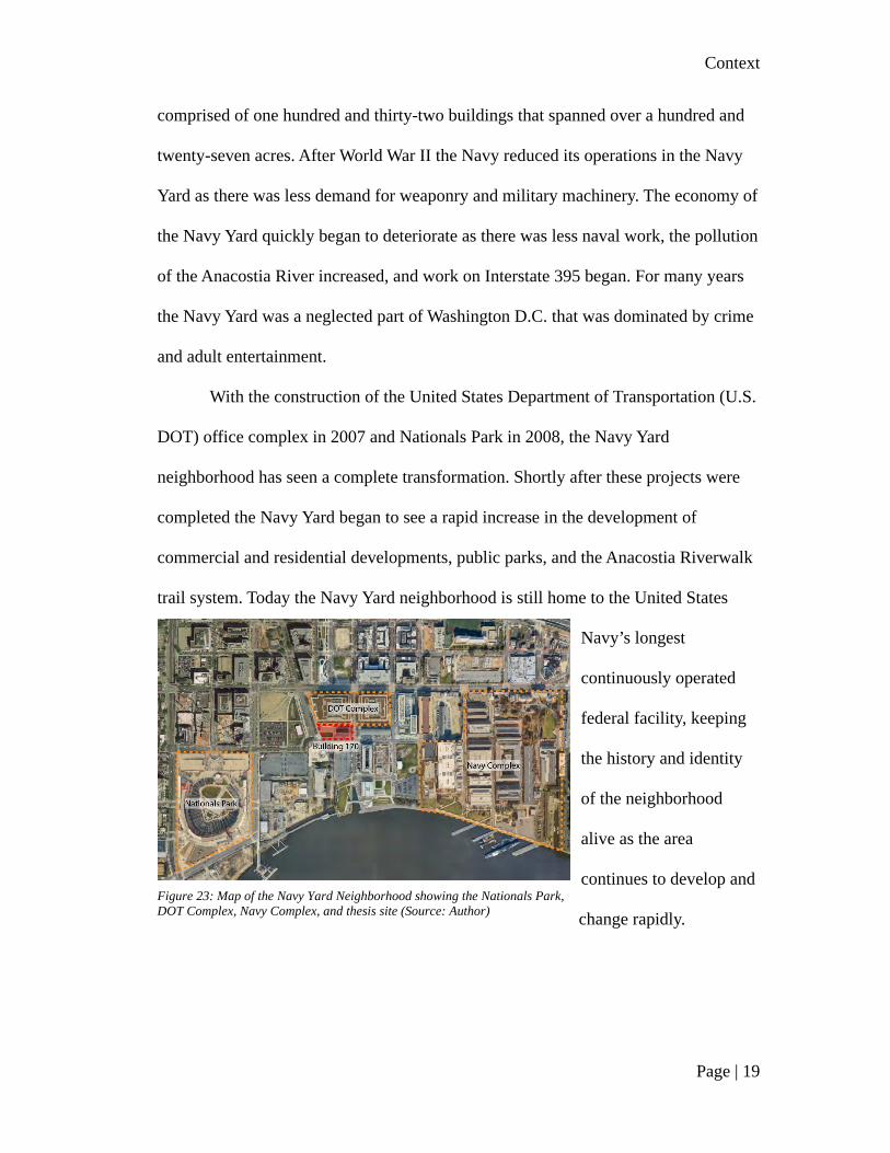
comprised of one hundred and thirty-two buildings that spanned over a hundred and
twenty-seven acres. After World War II the Navy reduced its operations in the Navy
Yard as there was less demand for weaponry and military machinery. The economy of
the Navy Yard quickly began to deteriorate as there was less naval work, the pollution
of the Anacostia River increased, and work on Interstate 395 began. For many years
the Navy Yard was a neglected part of Washington D.C. that was dominated by crime
and adult entertainment.
With the construction of the United States Department of Transportation (U.S.
DOT) office complex in 2007 and Nationals Park in 2008, the Navy Yard
neighborhood has seen a complete transformation. Shortly after these projects were
completed the Navy Yard began to see a rapid increase in the development of
commercial and residential developments, public parks, and the Anacostia Riverwalk
trail system. Today the Navy Yard neighborhood is still home to the United States
Navy’s longest
continuously operated
federal facility, keeping
the history and identity
of the neighborhood
alive as the area
continues to develop and
change rapidly. Figure 23: Map of the Navy Yard Neighborhood showing the Nationals Park, DOT Complex, Navy Complex, and thesis site (Source: Author)

Context
Page | 20
4.2 Site History
The site selected for this thesis is located a block from the Anacostia River
waterfront in the Navy Yard neighborhood, located north of Tingey Street SE, west of
3rd Street SE, east of New Jersey Avenue SE, and south of the DOT complex.
Building 170, historically known as “Electric Substation, Sub-Station B & Shop 5
Erecting19” is one of the last sites in the neighborhood that has not been adapted,
rehabilitated, or demolished for new construction. Building 170 covers about eight
thousand square feet and sits on about thirty-seven thousand square feet of plaza
space adjacent to the U.S. DOT and Federal Highway Administration building
complex.
19 United States Depatment of the Interior National Park Service. April 2007 (updated
October 2007). National Register of Historic Places Registration Form. Accessed October 27, 2019.
Figure 24: Building 170 in September 2019 (Source: Author)

Context
Page | 21
Building 170 was constructed in 1919 as part of the United States Navy
industrial complex, also known as the Navy Yard Annex, as a direct result of the
nation’s involvement in World War I. It was used following World War I and during
World War II for the production of naval weaponry and ordnance technology, serving
as a critical piece of day-to-day operations, housing switching equipment for the
control of ordnance production machines.20 After the wars, when the Navy downsized
the Navy Yard industrial complex, Building 170 was transferred to the General
Services Administration (GSA) along with fifty-five acres of land in 1963. GSA
planned to redevelop their newly acquired fifty-five acres of land for offices and
20 United States Depatment of the Interior National Park Service. April 2007 (updated
October 2007). National Register of Historic Places Registration Form. Accessed October 27, 2019.
Figure 26: Building 170, the Boilermaker Shops, the Foundry Lofts, and the Lumber Shed at the Yards Park in September 2004 (Source: https://www.jdland.com/)
Figure 25: Building 170, the Boilermaker Shops, the Foundry Lofts, and the Lumber Shed at the Yards Park in 2003 (Source: https://www.jdland.com/)

Context
Page | 22
mixed-use spaces for federal agencies. Part of GSA’s vision for the redevelopment
was to adapt the existing structures left over from the Annex industrial period but
many of the buildings never got the opportunity to be transformed under GSA.
In 2006, as construction
began on the new U.S. DOT
complex that is adjacent to the
thesis site, upgrades were made
to the property surrounding
Building 170. These upgrades
included the installation of
fountains, landscaping, and brick
pavers to create a minimal plaza
around Building 170. Currently,
the U.S. DOT uses the strip of the plaza between their complex and Building 170 as
an educational experience titled “Transportation Walk: The Evolution of America on
the Move.” Objects that have been a part of our nation’s history of transportation are
placed throughout the plaza, there is a series of three posted from the early 1900s that
advertise different means of transportation on the north side of Building 170.
Figure 27: Site adjacent to DOT complex surrounded by new construction (Source: Author)

Context
Page | 23
On January 3, 2008, Building
170 was designated as one of fifteen
contributing properties to the
Washington Navy Yard Annex
Historic District, the boundary
increase to the Washington Navy Yard
Historic District that was listed on the
National Register in 1973 and designated as a National Historic Landmark in 1976.
Building 170 has been deemed historically significant for its integral part of the
industrial complex at the Navy Yard Annex and its physical representation of the
Navy Yard’s expansion as a result of World War I, showing a similar design, scale,
and materials to other buildings that were built as part of the Navy Yard and Navy
Yard Annex21. Building 170 is also architecturally significant for its illustration of
early-twentieth-century power plant facilities. The following is the official National
Register of Historic Places description of Building 170:
“Building 170 is a three-story, linear, masonry building six structural bays (50 feet)
in width and ten structural bays (125 feet) in length. The building is capped by a gable roof
with a monitor at the ridge, a configuration that provides for the maximum natural light and
efficient ventilation for the interior. The monitor features full-length glazing set in original
multi-light industrial steel windows, as does the upper-most story of the north and south
elevations. Both the roof of the monitor and that of the main portion of the building is clad in
standing-seam metal. Brick pilasters delineate the fenestration present on all elevations. In
contrast to the horizontal bands of windows present in the monitor and at the upper-most story
21 United States Depatment of the Interior National Park Service. April 2007 (updated
October 2007). National Register of Historic Places Registration Form. Accessed October 27, 2019.
Figure 28: Condition of Building in September 2019 (Source: Author)

Context
Page | 24
of the north and south elevations, windows throughout the rest of the building occur as tall
groupings (spanning two or more stories) and emphasize the verticality of the building.
Original vehicular openings fitted with roll-up doors are centrally located at the first story of
the east and west elevations. Modifications to the south elevation include sheet metal patching
and brick infill of openings.22”
Today the Colonial Revival
steel-framed building stands
vacant and neglected besides
a weekly farmer's market
that occurs every Saturday,
weather permitting, on the
plaza, and sometimes spills
into the existing structure. The façade is covered in a locally-sourced red brick and is
exposed to the steel-framed construction on the interior.23 The metal shed roof and
continuous ridge monitor are exposed in the open interior of the space as are the
unpaved, dirt floors.
4.3 Site Selection Process
The site selection process for this thesis began by exploring areas of the east
coast that have a high concentration of existing structures that have been neglected
and/or have fallen into disrepair. To support this thesis, it was important to look for an
existing structure with a historical presence in an area of economic stability,
22 United States Depatment of the Interior National Park Service. April 2007 (updated
October 2007). National Register of Historic Places Registration Form. Accessed October 27, 2019. 23 District of Columbia Office of Planning. 2009. "District of Columbia Inventory of Historic
Sites." District of Columbia, 229. Accessed October 27, 2019.
Figure 29: Interior of Building 170 (Source: Developer Kelly Silverman)

Context
Page | 25
accessibility, and a connection to the surrounding community. Exploration began by
looking into the navy yards, port areas, and neglected industrial sites of Baltimore,
Boston, Philadelphia, New York, and Washington D.C. by analyzing the surrounding
neighborhood and the area’s plan for development. Many of these
neighborhoods/sites have been redeveloped in recent years or have a master plan for
redevelopment but few of them showed current economic stability for a community-
centered program that will bring new life to an existing, neglected structure.
The Navy Yard of Washington D.C. showed room for a community program
in an economically stable fabric that has undergone immense development since the
construction of Nationals Park and the Department of Transportation complex in the
mid-2000s. Because of the recent development, few existing buildings have not been
adapted or preserved. Building 170, just south of the Department of Transportation
complex, and Building 202, located just outside the Navy Yard complex, are the two
Figure 30 Existing buildings of the Washington D.C. Navy Yard neighborhood (Source: Author)

Context
Page | 26
remaining buildings of the Navy Yard neighborhood that have not been adapted or
preserved.
Building 170 proved to be a promising site option for this thesis because of its
historic significance to the Navy Yard neighborhood, accessibility, and urban context.
As one of the fourteen contributing properties to the Washington Navy Yard Annex
Historic District, Building 170 has the potential to support the adaption of an existing
structure to become a building that supports and encourages community connection.
Baltimore’s Port Covington is another site option that showed strong potential
to have an existing structure that could support this thesis. Over the last two decades,
there have been many proposals to redevelop the Port Covington area from an
industrial waterfront to a neighborhood with offices, residential, shopping,
restaurants, and waterfront properties. Recently Sagamore Development, a private
real estate firm owned by Under Armour CEO Kevin Plank, has come up with a
Figure 31: Site Breakdown of Building 170 (Source: Author)

Context
Page | 27
master plan for the area that includes a new state-of-the-art campus for Under Armor.
The first phase of construction is scheduled to begin in January of 2020 and the
redevelopment of Port Covington will be underway. This masterplan by Sagamore
Development aims to demolish many of the existing buildings on the site to make
way for new buildings that fit the master plan. An existing structure on this site that is
set for demolition could be saved and adapted to stand as a precedent for reusing
existing structures as a sustainable construction option.
The existing industrial building in the northwest corner of the Port Covington
site shows the potential to illustrate the benefits of reusing an existing structure for
sustainable construction and environmental benefits. The building sits just south of
Interstate 95 and west of the Port Covington exit ramp. In Sagamore’s masterplan of
Port Covington, this building will be demolished to make way for a civic, mixed-use
program. As this site will be surrounded by 1.38 million sqft office, 337,450 sqft of
retail, 976,667 sqft of residential, and 285,000 sqft of hotel in twelve city blocks of
Figure 32: Sagamore Development's Master Plan for Port Covington (Source: Baltimore Sun)

Context
Page | 28
development, the existing building could be adapted to represent the industrial history
of the Port Covington area and be an example for the future development of this area
to show the benefits of reusing an existing structure.
Boston, Massachusetts’ naval and industrial history provided many sites
throughout the city to research and explore as possible site options. The Charleston
Navy Yard, the Seaport neighborhood, abandoned mill buildings, and abandoned
breweries are all viable contenders as a possible site to support this thesis. Ultimately,
the Alley-Eblana Brewery in the Mission Hill neighborhood stood out as a great site
option for this thesis to explore sustainable adaptive reuse within a residential fabric.
The Alley-Eblana Brewery site is different from the Washington D.C. site and
Baltimore site because it sits in a fabric of mostly single-family residential homes.
The Alley-Eblana Brewery was built as one of Boston’s thirty-one breweries in 1895.
Today it is on the Preservation Massachusetts’ Most Endangered Historic Resources
Figure 33: Site Breakdown of Port Covington (Source: Author)

Context
Page | 29
List and has sat vacant since 2004. This site has the potential to become the center of
the community due to its connection and accessibility to the surrounding community.
Overall, each of the sites, Building 170 in the Washington D.C. Navy Yard;
Port Covington in Baltimore, Maryland; and the Alley-Eblana Brewery in the Mission
Hill neighborhood of Boston, Massachusetts have qualities that can support this thesis
to show the sustainable benefits of adaptively reusing an existing structure. In the site
matrix below (Figure 19), each building has been given a numerical ranking to
compare the site’s properties and characteristics to analyze which of the three sites
will best support this thesis. The three most important characteristics of the site are its
historical presents, the quality and importance of the existing structure, and the
economic stability of the surrounding area. With the intent for the site’s program to
benefit, educate, and connect the surrounding community it is important for the
building to express the history of the area, promote the identity of the community, and
Figure 34: Site Breakdown of Alley-Eblana Brewery (Source: Author)

Context
Page | 30
be supported by the existing economy in the area. Other characteristics of the site that
have been analyzed are the site’s accessibility, connection, surrounding context, and
buildable space.
Figure 35: Comparison of Building 170, Port Covington, and Alley-Eblana Brewery (Source: Author)
Figure 36: Site Matrix (Source: Author)

Context
Page | 31
4.4 Site Analysis
Today, Building 170 is immersed in a very different fabric than the Navy
Yard’s original industrial context. Since the construction of the Department of
Transportation complex and Nationals Park in 2008, the Navy Yard neighborhood has
experienced rapid growth in the area’s development. Building 170 is one of the few
properties left in the neighborhood that has not been purchased for development
and/or redevelopment.
Currently, the Navy Yard neighborhood is home to ten thousand five hundred
residents in six thousand eight hundred existing units and will be home to thirty
thousand residents at full build-out, with five thousand one hundred units currently
under construction.24 The neighborhood contains two major league sports stadiums:
Nationals Park, home of the Washington Nationals, completed in 2008, and Audi
Field, home to the D.C. United, completed in 2018. These stadiums are immersed in
four hundred eighty thousand square feet of retail fabric and four hundred twenty
thousand square feet of retail that is currently under construction. The Navy Yard
neighborhood currently contains a Harris Teeter and Whole Foods market among
many restaurants and retailers. At full build-out, the Navy Yard will offer sixty
restaurants and thirty-four retailers. There are also nineteen existing office buildings
in the Navy Yard neighborhood with two office buildings currently under construction
and five office buildings proposed to break ground in the next five years to hold
thirty-five thousand employees over 6.5 million sqft25.
24 Capitol Riverfront BID. 2019. Capitol Riverfront. Accessed November 11, 2019 25 Capitol Riverfront BID. 2019. Capitol Riverfront. Accessed November 11, 2019

Context
Page | 32
The Navy Yard neighborhood is just six blocks from the capitol easily
accessible by many different forms of transportation. The neighborhood is just a ten-
minute drive from Ronald Reagan Washington National Airport off Interstate-295,
Interstate-395, and Interstate-695. It is easily accessible by ten Washington
Figure 38: Land use of the Navy Yard neighborhood (Source: Author)
Figure 37: Future land use of the Navy Yard neighborhood (Source: Author)

Context
Page | 33
Metropolitan Area Transit Authority (WMATA) bus routes, the Circulator bus, and
four metro lines, mainly the green line. The neighborhood contains fifty dock slips,
eight Capital Bikeshare docks, and a variety of scooter shares.
Building 170 shares a site with a Capital Bikeshare docking station, just on the
south side of the building. The site is within a ten-minute walking radius of six
WMATA bus stops and a three-minute walk from the green line Navy Yard-Ballpark
Station. Building 170 is a five-minute drive from Interstate-295, Interstate-395, and
Interstate-695.
Figure 39: Walking radius to Capital Bikeshare locations (Source: Author)

Context
Page | 34
Figure 40: Walking radius to bus stops (Source: Author)
Figure 41: Walking radius to metro stops (Source: Author)
Preservation and Adaptive Reuse Regulations
Page | 35
Chapter 5 Preservation and Adaptive Reuse Regulations
5.1 Introduction
Preservation is defined by the National Park Service and U.S. Department of
the Interior “as the act or process of applying measures necessary to sustain the
existing form, integrity, and materials of a historic property.26” Whereas adaptive
reuse is the process that transforms an unused or ineffective item into a new item that
is used for a different purpose when the original cannot support the item anymore.
Adaptive reuse is a creative means to recycling the existing and the best adaptive
reuse practices are respectful to the buildings original purpose, highlight the building
architectural features, and express the buildings historical significance, especially
when the site has been deemed historic at any level; national, state/district, and/or
local. As the site of this thesis, Building 170, is one of fifteen contributing properties
to the Washington Navy Yard Annex Historic District, some regulations should be
considered at the federal and district levels to properly adapt the structure and honor
the building’s history.
Historic preservation is regulated at three levels: Federal, State, and local.
The government began regulating historic properties with the establishment of the US
National Trust for Historic Preservation in 1949. In 1966 the Nationals Historic
Preservation Act was passed, giving the Secretary of the Interiors a detailed role in
26 National Park Service U.S. Department of the Interior. n.d. Preservation as a Treatment and
Standards for Preservation-Technical Preservation Services, National Park Service. Accessed
December 10, 2019.

Preservation and Adaptive Reuse Regulations
Page | 36
the national preservation process and created the National Register of Historic Places,
State Historic Preservation Offices, and Section 106 Review process.
5.2 Federal Benefits and Regulations
Because Building 170 is a contributing property to a National Registered
Historic District the site is considered in federal planning, eligible for tax credits, and
eligible for federal grants for historic preservation. Building 170 and the entire Navy
Yard Annex District must be considered by federal agencies, federally licensed, and
federally assisted projects under Section 106 of the National Historic Preservation Act
of 1966, allowing the Advisory Council on Historic Preservation (ACHP) to comment
and defend the district from being affected by federal projects. This process is how
Building 170 and its neighbor, The Boilermaker Shops, were maintained at their
existing condition when the Department of Transportation complex was constructed
in 2006.
As a contributing property to the Navy Yard Annex Historic District, Building
170 is eligible for twenty percent tax credit for certified rehabilitation of income-
producing certified historic structures. These tax credits can be combined with a
straight-line depreciation period for thirty-one and a half years for the depreciable
basis of the rehabilitated building reduced by the amount of the tax credit claimed.27
The site is also eligible for federal grants when funding is available.
Since the property is not under federal ownership, there are no restrictions
placed on the property just because it is a contributing property to a National
27 National Parks Service. n.d. National Register of Historic Places FAQs. Accessed December 12, 2019.

Preservation and Adaptive Reuse Regulations
Page | 37
Registered Historic District. If the property is to use federal assistance in the form of
grants and/or tax credits, then the Advisory Council on Historic Preservation must be
given an opportunity to comment on the project.
5.3 District of Columbia and Southeast Federal Center Local Regulations
With Building 170 originally being a federally owned property that has been
turned over to a private developer it is now managed through a master plan, historic
covenant, programmatic agreement, and design guidelines making Building 170 one
of the more complicated properties in the District of Columbia. Under the Southeast
Federal Center Revised Master Plan, established in 2003, the Southeast Federal
Center (SFC) was proposed to be developed as a mixed-use neighborhood of
residential, office, retail, recreational, and cultural uses28. To avoid, minimize, and
mitigate adverse effects on any historic properties in the SFC, local Historic
Preservation Design Guidelines were established with the consultation of the District
of Columbia SHPO and ACHP to guide to historic structures of the revised master
plan.
“Adverse Effect” is defined in the SFC design guidelines as “the effect of an
undertaking on a resource that diminishes the integrity of the resource’s location,
design, setting, materials, workmanship, feeling or association.29” Building 170 and
all new construction adjacent to Building 170 will be reviewed under the Historic
Preservation Design Guidelines. The preservation design goals of the design
28 2003, edited June 2007. "Historic Preservation Design Guidelines for Development of the
Southeast Federal Center." Washington D.C. Office of Planning. Accessed December 13, 2019. 29 2003, edited June 2007. "Historic Preservation Design Guidelines for Development of the
Southeast Federal Center." Washington D.C. Office of Planning. Accessed December 13, 2019.

Preservation and Adaptive Reuse Regulations
Page | 38
guidelines are to preserve National Register-Eligible historic structures, create a
visual relationship between historic buildings, and establish an area of special
architectural character that enhances the historic context. Building 170 is a
contributing property to a National Register Historic District but has not been deemed
a National Register-Eligible property, meaning that under these guidelines Building
170 is of the historic buildings that should be visually connected and enhances the
historic context of the area but its not one of the six properties under the SFC design
guidelines that must be preserved.
Building 170 can be adapted properly, complying with the Programmatic
Agreement and Historic Covenant of the District of Columbia as stated below:
“• The treatment of fenestration may vary depending on the significance and condition of the
historic fenestration or building, or on the practicability of repair versus replacement.
Potential treatments of historic fenestration include retention and repair, replacement to match
the existing configuration and muntin detailing, or replacement recalling the configuration
and detail of the historic fenestration.
• Alterations to building facades may include some adjustments to the sizes of existing
masonry openings (for example, as shown in the illustrative diagrams). Enlargement of
infilled masonry openings to their historic configuration is encouraged.
• Existing masonry will be cleaned in a manner consistent with the Secretary’s Standards.
Exposed masonry will generally not be painted and will be repaired and repointed only as
necessary. Repairs will be undertaken with masonry units and mortar that match or are
compatible with their original counterparts.
• Existing character-defining rooflines, monitors, skylights, ventilators, and other significant
features will be maintained where possible. Original roofing materials will be repaired where
possible and replaced in kind where necessary. New mechanical equipment and penthouses
will be located and designed to minimize visual impact.

Preservation and Adaptive Reuse Regulations
Page | 39
• Planned building additions will be compatible with the original building in form, materials,
and color, per the Secretary’s Standards.
• Removal of Non-Contributing additions will be undertaken so as not to damage the
building or leave unsightly scars. Original fabric exposed through the removal of additions
will be generally restored to its original configuration.
• Alterations needed to address floodplain issues require careful consideration and will be
reviewed on a case-by-case basis.30”
30 2003, edited June 2007. "Historic Preservation Design Guidelines for Development of the
Southeast Federal Center." Washington D.C. Office of Planning. Accessed December 13, 2019.

Mass Timber
Page | 40
Chapter 6 Mass Timber
6.1 Introduction
In a period of climate change, it is important to take advantage of the solutions
that are naturally provided to us. Timber has been a primary material of construction
since the first timber home was built in the Mesolithic period in Great Britain, dating
back to 8000 B.C. Wood construction has proven to be a reliable material as there are
still timber structures from nearly a thousand years that are still standing today. In
North America, some indigenous people and early settlers relied on timber
construction for its efficiency and proximity to settlements. Our continent is covered
in trees ready to help us fight climate change. Timber is an organism that helps to
remove CO2 from the atmosphere by collecting CO2 and storing it within the material
over the timber’s life cycle. To decrease the levels of CO2 in the atmosphere we need
to maintain existing forest land, increase tree coverage, and harvest wood sustainably.
6.2 What is Mass Timer?
Through mass timber
construction, we can not only store CO2
within our forests, but we can also
remove CO2 from our atmosphere from
the built environment. Mass timber is a
construction type of large genetically
engineered wood products that are
typically made through a process of laminating and compressing multiple layers of
Figure 42: Interior of the Wood Innovation and Design Centre (Source: Ema Peter via Architecture Magazine)

Mass Timber
Page | 41
wood together to produce solid pieces of wood. Cross-laminated timber (CLT),
dowel-laminated timber (DLT), glue-laminated timber (glulam), laminated veneer
lumber (LVL), laminated strand lumber (LSL), nail-laminated timber (NLT), and
wood-concrete composites are all mass timber products. The three most commonly
used mass timber products are CLT, NLT, and glulam.
• CLT panels are made up of dimensional
lumber that is stacked and glued together in
layers perpendicular to one another. CLTs
are made using three, five, or seven layers of
dimensional lumber and are most commonly
used for floors, walls, and roofs because of its two-way span capabilities.
Figure 43: Mass Timber Products Matrix (Source: Author)
Figure 44: CLT board (Source: Technology in Architecture)

Mass Timber
Page | 42
• DLT is created by compressing
dimensional lumber together with
wood dowels and moisture-resistant
adhesive. Because the grains of the
dimensional wood run together in a
DLT panel, DLT is most commonly used for floors and roofs.
• Glulam is created form bonding dimensional
lumber on edge to one another using a moisture-
resistant adhesive. A glulam member can come in
a standard or custom size. Its depth can range
from 6” to 72” and its width can range from 2.5”
to 10.75”. Glulam is commonly used for beams
and columns in residential and commercial structures.
• LVL is made from compressing multiple thin layers of
wood together with a moisture-resistant adhesive.
Because LVL is typically sized to be compatible with I-
joists, LVL is typically used for headers, beams, and
rim boards. LVL can be up to four feet in width and
eighty feet long in size.
Figure 45: DLT panel (Source: Meng Gong)
Figure 46: Glulam beam (Source: bimobject)
Figure 47: LVL (Source: Element Five)

Mass Timber
Page | 43
• LSL is made up of pieces of wood that could potentially be too weak or small
to stand on its own. These pieces of wood are compressed together using a
moisture-resistant adhesive. LSL is
typically used as framing boards for floor
joists and support beams, sill plates, and
door cores.
• NLT is made from stacking layers of dimensional lumber on end together
using nails or screws. NLT is a construction method that has been used for
nearly a century and has been designed over time to be more sustainable. NLT
typically comes in the nominal
thicknesses of 2x, 3x, and 4x with
a width ranging from 4” to 12”. It
is commonly used for floors and
roofs, it has also been used for
elevator shafts.
• Wood concrete composites are concrete
slabs that are connected to wood beams
or a laminated wood slab with a shear
connection. Wood concrete composites
are typically used as floor and deck
systems.
CLT was created in the 1990s by Gerhard Schichhofer in Austria and grew in
popularity throughout Europe over the next decade. In 2002 Austria published its first
Figure 48: LSL (Source: European Wood)
Figure 49: NLT Panel (Source: Meng Gong)
Figure 50: Wood Concrete Composite (Source: Structure Craft)

Mass Timber
Page | 44
national guideline for mass timber construction. As
mass timber reach grew to Australia, Canada, and
the United States it was included in the 2015 edition
of the International Building Codes (IBC). Today
the tallest mass timber structure, the Mjosa Tower,
stands at 280 ft tall in Brumunddal, Norway. This
eighteen-story, mixed-use building is made up of
CLT and glulam construction. Completed in March
2019, the architect (Voll Arkitekter), the structural
engineer (Moelven Limitre), and the timber supplier (Moelven Limitre) used locally
sourced timber to create the mass timber products of the building.
6.3 Sustainable Properties
Historically, just like timber construction, concrete has also been used by
ancient civilizations where wood was not as readily available. As concrete and timber
materials stood as two of the most popular construction materials throughout history,
both had very different impacts on the environment. Concrete remains an
unrenewable resource while timber can be reused. With the popularity of steel and
concrete construction rising alongside the industrial revolution so did the impact
construct has on our environment. It has been found through a study at the University
of Washington and Yale University that if the expansion of wood construction was to
be limited to the annual growth of wood, the combination of emissions reduction and
carbon sequestration of mass timber construction has the potential to eliminate
Figure 51: Mjøsa tower. (Source: Nina Rundsveen via metalocus.es)

Mass Timber
Page | 45
construction emission altogether31. Timber buildings require less energy from the
harvesting process through manufacturing and construction to the end of the
building’s life compared to concrete and steel buildings. Because trees grow across
our continent, materials for wood construction can be sourced locally to reduce
transportation costs and energy. Timber materials also weigh less than steel and
concrete construction materials further reducing the impact transportation of
construction materials can have on the environment.
Timber is different from steel and concrete because it is a natural material that
can be regrown and reproduced. Wood is a renewable, biodegradable, non-toxic, and
energy-efficient building material.32 Mass timber has proven to leave a lighter carbon
footprint than other building
materials that are more fossil
fuel-intensive. The lifecycle of
a timber structure proves to
produce significantly lower
greenhouse gas emissions than
other construction types
because of its sustainable
material properties,
transportation, and construction
process, and ability to remove
31 Frank Lowenstein, Brian Donahue, and David Foster. 2019. "Let's Fill Our Cities with
Taller, Wooden Buildings." Accessed October 12, 2019. 32 Evan. 2016. "What Building Material (wood, steel, concrete) Has The Smallest Overall
Environment Impact?” Accessed October 13, 2019.
Figure 52: Lifecycle of mass timber construction (Source: Author)

Mass Timber
Page | 46
CO2 from the environment. A study shows that a timber house in both cold and warm
climates has 31% less life-cycle emissions that a concrete house and 26% less life-
cycle emissions than a steel house.33 The wood products of a timber structure
typically store more carbon than what would be emitted during the harvest,
manufacturing, construction, and end-use of the structure making timber structures a
reliable weapon against climate change.
Mass timber construction can be a faster, more efficient construction process.
According to Bernhard Gafner of Fast + Epp, a structural engineering firm, a mass
timber project can be constructed 25% faster, require up to 90% less transportation,
and 75% fewer workers on-site than that of a steel and concrete structure.34
Structurally, mass timber construction has also proven to offer high-performance
value in fire protection and
seismic resistance. A CLT
panel’s char rate can meet the
two- and three-hour fire
resistance code without
gypsum protection:
“One series of full-scale compartment tests compared the performance of light-gauge
steel, light-frame wood, and CLT. Tests included a three-story encapsulated CLT apartment
simulation that ran for three hours. Results of the apartment simulation show the effectiveness
of encapsulation in significantly delaying CLT’s potential contribution to fire growth and
proved that the structure can withstand complete burnout. Another test focused on a 25½-foot
33 "Sustainability." Think Wood. Accessed October 13, 2019. 34 American Wood Council. n.d. Mass Timber in North America: Expanding the possibilities
of wood building design. reThink Wood. Accessed October 13, 2019.
Figure 53: CLT char illustration (Source: Think Wood, Edited by Author)

Mass Timber
Page | 47
CLT stair/elevator shaft (exposed on the inside face with two layers of gypsum protection on
the fireside) and studied the smoke propagation and leakage as well as its structural stability
as a fire exit. The test ran for 2 hours and showed no sign of smoke or heat penetration into
the shaft.35”
Using CLT components in lateral systems have also been designed to meet the
building code standards and have been engineered using advanced performance-based
seismic design procedures.
Hopefully, mass timber construction will continue to expand its reach across
our profession so that professionals can take advantage of a building material that
holds many sustainable properties that can benefit our planet in a period of climate
change. We need to realize the impact we have had on our environment over the past
couple of centuries and
revaluate how we use
unsustainable materials so
that we can create a better
atmosphere for us and the
coming generations.
35 American Wood Council. n.d. Mass Timber in North America: Expanding the possibilities
of wood building design. reThink Wood. Accessed October 13, 2019.
Figure 54: John W. Oliver Design Building at UMass Amherst (Source: auburn.edu)

Architecture Intervention
Page | 48
Chapter 7 Architecture Intervention
7.1 Program Selection
As the site of this thesis sits in the Navy Yard neighborhood, a community that
is seeing rapid change and development it became apparent that the architecture that
has risen in the area has been driven primarily by developers who have not been
keeping the civic needs of the people in mind. The area is in dire need of a
community space that speaks to the heart of the people who live there and with all the
construction going on, the neighborhood still lacks a local community space. A public
community library would be a great opportunity for a community space, but the
closest permanent public library is the SE neighborhood Library which is a twenty-
minute walk from the heart of the navy yard.
Figure 55: Walking radius to local Libraries (Source: Author)
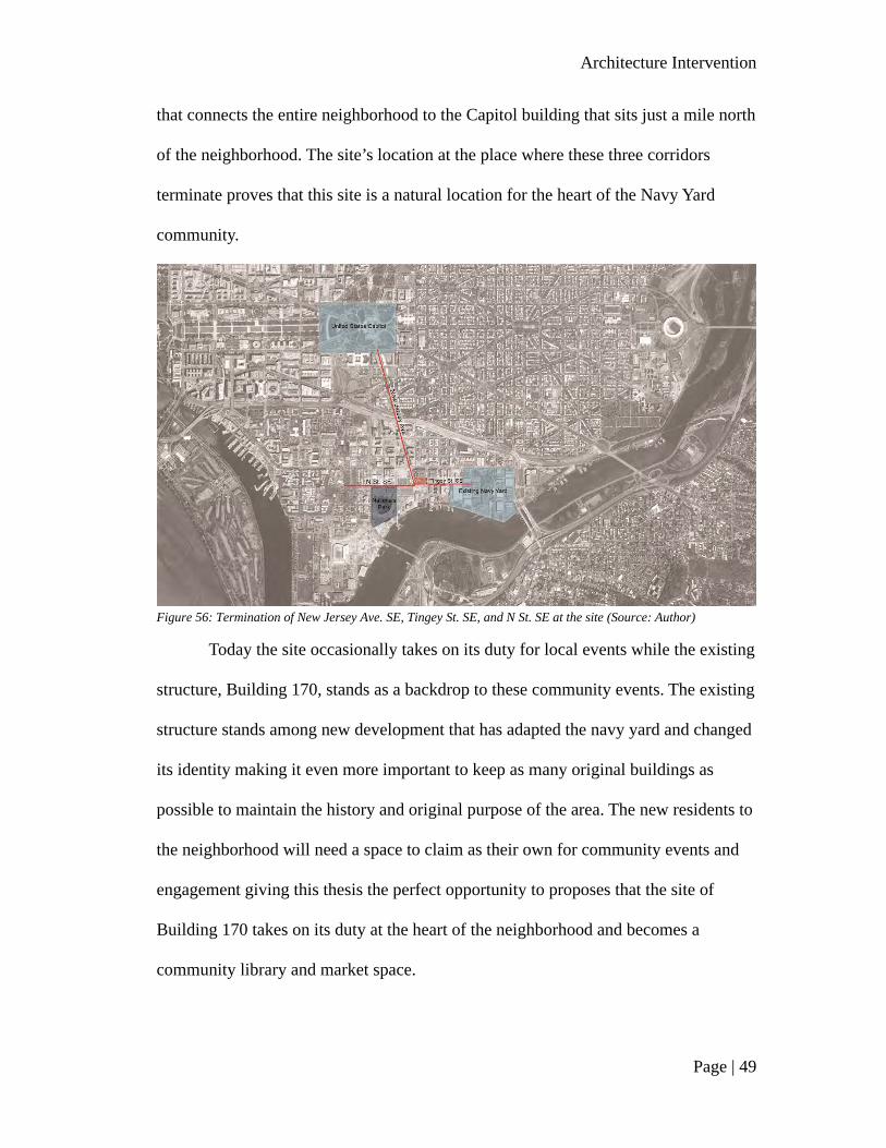
The site this thesis is where three corridors terminate: N st SE, the corridor
that connects the site to Nationals Park; Tingey St SE, the corridor that connects the
site to the existing Navy Yard; and most importantly, New Jersey Ave. the corridor
Architecture Intervention
Page | 49
that connects the entire neighborhood to the Capitol building that sits just a mile north
of the neighborhood. The site’s location at the place where these three corridors
terminate proves that this site is a natural location for the heart of the Navy Yard
community.
Figure 56: Termination of New Jersey Ave. SE, Tingey St. SE, and N St. SE at the site (Source: Author)
Today the site occasionally takes on its duty for local events while the existing
structure, Building 170, stands as a backdrop to these community events. The existing
structure stands among new development that has adapted the navy yard and changed
its identity making it even more important to keep as many original buildings as
possible to maintain the history and original purpose of the area. The new residents to
the neighborhood will need a space to claim as their own for community events and
engagement giving this thesis the perfect opportunity to proposes that the site of
Building 170 takes on its duty at the heart of the neighborhood and becomes a
community library and market space.

Architecture Intervention
Page | 50
Figure 57: Existing Site Condition (Source: Author)
Figure 58: Proposed Site Condition (Source: Author)
7.2 Urban Historic Layers
The design of this thesis centers the two community programs off of a central
plaza that allows the programs to flow from the interior to the exterior. The central
plaza illustrates the Navy Yard Annex historic district through the existing building,
plaza elements, and perforated metal screen on the east façade of the library that
illustrates the fifteen contributing properties to the historic district. The plaza could

Architecture Intervention
Page | 51
serve many community activities, for example, on a warm Saturday afternoon when
the food hall is opened from the interior to the exterior the program could spill out on
to the plaza and engage the surrounding community.
The Navy Yard plaza connects through the building to the Navy Yard
transportation history promenade. This promenade walks you through the different
forms of transportation that have been created in the Washington Navy Yard Annex in
the same way the existing DOT history promenade, which sits parallel to the Navy
Yard transportation history promenade, takes you on an experience through the ways
transportation have changed throughout the history of our nation. These promenades
that sit between the site and the DOT office complex create an opportunity for the
community to be reminded of not only local history but also national history through
physical elements like travel posters from the nineteenth and twentieth centuries,
Figure 59: Navy Yard Plaza facing Building 170 (Author: Source)

Architecture Intervention
Page | 52
steamboat pipes, a retired naval ship’s anchor, and many other elements that speak to
the industrial economy of the Navy Yard Annex and the history of the DOT.
The recently finished plaza that sits south of the site creates the perfect
opportunity for a monument that could mark the Navy Yard Annex Historic District
while acting as a terminating object that would pull you into the heart of the
community from New Jersey Ave. As visitors would proceed down New Jersey the
monument would sit in comparison to the entrance of the library portion of the
program. The history of the navy yard begins to come to life in the façade of the new
structure through the repurposed metal of maybe an old naval ship or a demoed
building from the navy yard that has been given new life in a perforated metal screen
that illustrates old maps of the area. Figure 62 illustrates how the etchings of a 1935
plan of Washington D.C. on the North West corner of the perforated metal screen
begins to take visitors through the history of the area moving to a 1935 master plan of
the Navy Yard Annex on the west façade. It is through these urban elements that the
design of this thesis speaks to the history of the area and most importantly, honors the
Figure 60: Proposed Site Plan highlighting historic urban elements (Source: Author)
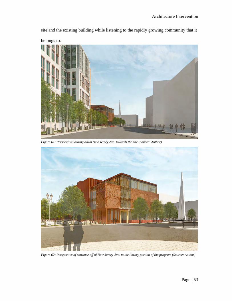
Architecture Intervention
Page | 53
site and the existing building while listening to the rapidly growing community that it
belongs to.
Figure 61: Perspective looking down New Jersey Ave. towards the site (Source: Author)
Figure 62: Perspective of entrance off of New Jersey Ave. to the library portion of the program (Source: Author)

Architecture Intervention
Page | 54
7.3 Design
As honoring the existing is a driving factor behind the design of the thesis the
program of the new building, the library, mirrors that of the existing building, the
food hall, connected by a loggia circulation that is continued from floor to floor with
the back of house off to the north.
Figure 63: 1st Floor Plan - illustration of program overview (Source: Author)
Figure 64: Longitudinal Section - illustration of program (Source: Author)
The longitudinal section through the site illustrated in Figure 64 shows how
the primary areas of program stem off the plaza, separated by an atrium and
circulation in both the library and food hall. Both buildings stack the program from

Architecture Intervention
Page | 55
most public to the least amount of energy. The food hall’s first floor is primarily
dominated by stalls and market kitchens moving up to the second-floor mezzanine
that takes on more of an open and interactive restaurant floor plan. In the library, the
first floor contains a reading stair that draws visitors up from the main desk and
community space to the stacks and open reading areas of the library. Moving up the
floors of the library, the stack spaces become quieter as the children’s library is on the
first floor under the reading stair, allowing the stair to double as an acoustical
separator to the rest of the stacks moving up to the top floor that acts more as study
space with private meeting rooms and computer spaces.
Visitors enter the building in the circulation loggia allowing for a direct flow
between the two buildings, with a central café and attached newspaper and magazine
stacks off to the north of the circulation between both program’s back of house
spaces. The stalls of the food hall are spaced off the existing structural grid of
Building 170 and create a central path of circulation through the building and up to
the second floor.
Figure 65: 1st Floor Plan (Source: Author)
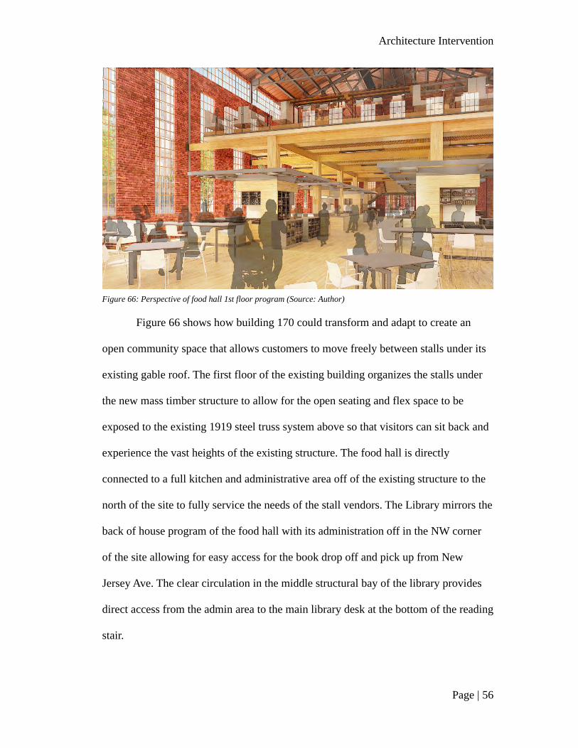
Architecture Intervention
Page | 56
Figure 66 shows how building 170 could transform and adapt to create an
open community space that allows customers to move freely between stalls under its
existing gable roof. The first floor of the existing building organizes the stalls under
the new mass timber structure to allow for the open seating and flex space to be
exposed to the existing 1919 steel truss system above so that visitors can sit back and
experience the vast heights of the existing structure. The food hall is directly
connected to a full kitchen and administrative area off of the existing structure to the
north of the site to fully service the needs of the stall vendors. The Library mirrors the
back of house program of the food hall with its administration off in the NW corner
of the site allowing for easy access for the book drop off and pick up from New
Jersey Ave. The clear circulation in the middle structural bay of the library provides
direct access from the admin area to the main library desk at the bottom of the reading
stair.
Figure 66: Perspective of food hall 1st floor program (Source: Author)

Architecture Intervention
Page | 57
Another driving concept to this thesis was leaving the glulam and CLT
structure exposed to show the timber in contrast to the existing masonry and steel
structure. As mass timber is a construction method that has been growing in recent
years but has yet to be fully accepted, exposing the structure from the interior to the
exterior in such a public building would allow visitors to learn about this sustainable
construction material firsthand. Figure 67 shows how the reading stair builds from the
CLT floor to open stadium-style seating for potential lectures and community events
while doubling as a continuation of the library stacks and reading areas. Underneath
the reading stair is the children’s library that is guarded by a security desk at the
entrance off of the circulation loggia. With this same idea of security repeated on the
ground level of the community daycare. The secondary programming of the daycare
resides on the first floor allowing the primary programming of the daycare in the
lower level to have direct access to the outdoor play spaces provided by in
environment atrium.
Figure 67: Perspective showing reading stair on the 1st floor of the library program (Source: Author)

Architecture Intervention
Page | 58
Figure 68: Lower Level Floor Plan (Source: Author)
The environment atrium draws in air from above, cleaning and passively
cooling it before it enters the atrium while using plants to bio-filter pollutants. The
glass box façade allows for natural daylight to filter into the lower level spaces of the
daycare to provide interactive learning and play space for the kids. This atrium is one
of four ways that the lower level receives natural light. The Environment atrium
provides natural light to most of the daycare except for the three-to-five-year-old
room which gets its natural light from above skylight towers. The third source of
natural light to the lower level is the library’s glazed fire stair that provides natural
Figure 69:Perspective of the exterior space in the daycare provided by the environment atrium (Source: Author)

Architecture Intervention
Page | 59
light into the daycare and the lower level maker space. The maker space is a part of
the library program that provides community members the opportunity to work
collaboratively using tools they may not have available to them at home in such an
urban area. The fourth way in which the lower level receives natural light is through
the green wall light wells that double as irrigation for the stormwater collection
system that services the site.
Figure 70: 2nd Floor Plan (Source: Author)
Figure 71: Perspective of the library stack areas (Source: Author)

Architecture Intervention
Page | 60
As we move up the building to the second floor, the library reading stair leads
to an open reading space that flows into the first level of the library stacks. The stacks
have a direct view below to the environment atrium and adjoining plaza as well as the
atrium above the reading stair. Across the circulation loggia from the stacks is the
local history room, a place that could potentially house some of the records there are
on the area that is currently in the College Park National Archives facility.
Figure 72: Perspective of 2nd-floor terrace space that looks on to the Navy Yard Plaza below (Source: Author)
The second floor of the library is connected to the food hall through the
adjoining terrace that serves as an outdoor space overlooking the central plaza below.
Directly off the terrace entering the food hall, the programming mirrors that of the
library in the private learning experience of the teaching kitchen that stems from the
second level of the existing structure. The second level structure of the food hall sits
off the existing, allowing the new to lightly touch the standing 1919 shell as the
second level provides extra space for the food hall experience. Visitors can experience
the vast heights of the industrial building as they sit down and relax while enjoying

Architecture Intervention
Page | 61
the food available throughout the food hall under the exposed steel trusses that date
back to 1919.
The third floor of the library repeats that of the second floor with more stack
space sandwiched between the environment atrium and the atrium that overlooks the
reading stair below. This floor also contains more private reading rooms in the north
bay of the program.
Figure 74: 3rd Floor Plan (Source: Author)
Figure 73: Perspective of the 2nd level of the food hall (Source: Author)

Architecture Intervention
Page | 62
The fourth floor of the library is the quietest of the floors with an open
computer lab and more opportunities for reading and studying spaces. This floor
contains four private collaborative spaces and two exterior terraces in the North West
and North East corners of the program. Figure 76 illustrates how the top floor of the
library program is connected to the reading stair below through the stack levels to the
glulam trusses above.
Figure 75: 4th Floor Plan (Source: Author)
Figure 76: Perspective of the top floor of the library and atrium glulam truss system (Source: Author)
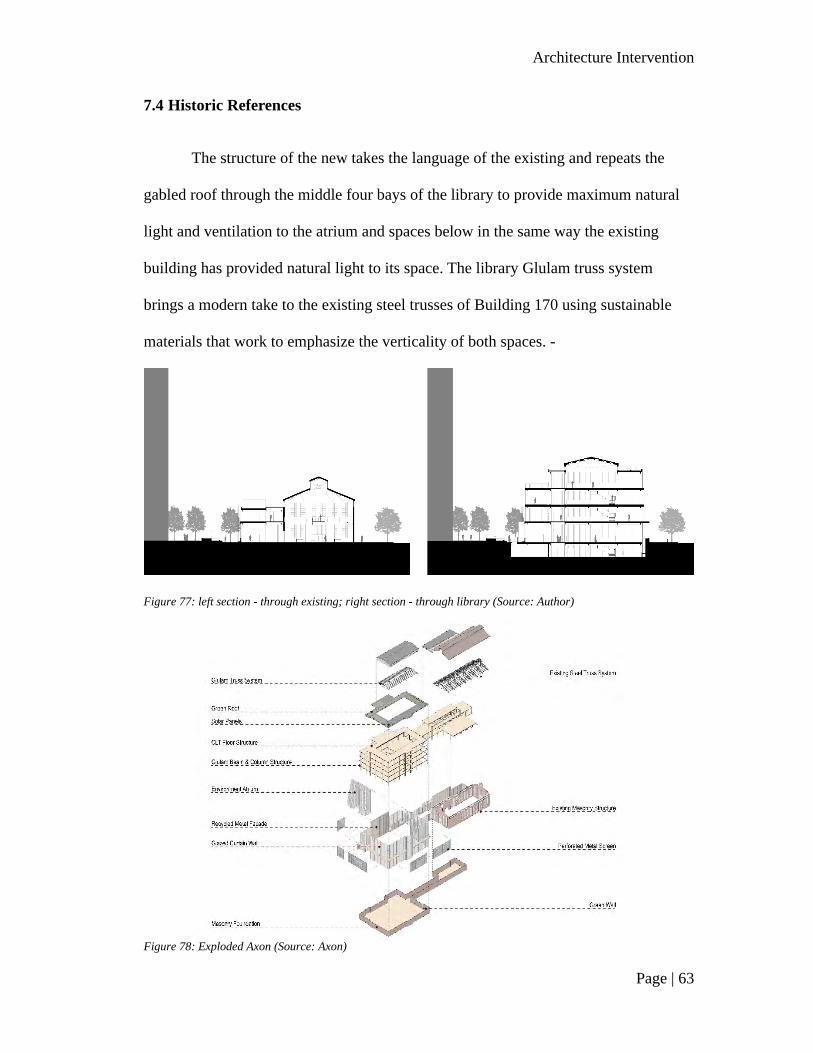
Architecture Intervention
Page | 63
7.4 Historic References
The structure of the new takes the language of the existing and repeats the
gabled roof through the middle four bays of the library to provide maximum natural
light and ventilation to the atrium and spaces below in the same way the existing
building has provided natural light to its space. The library Glulam truss system
brings a modern take to the existing steel trusses of Building 170 using sustainable
materials that work to emphasize the verticality of both spaces. -
Figure 77: left section - through existing; right section - through library (Source: Author)
Figure 78: Exploded Axon (Source: Axon)

Architecture Intervention
Page | 64
The exploded axon of figure 78 dives deeper into the relationship between the
two structures. The exploded axon illustrates how the glazed curtain walls of the mass
timber structure takes from the existing vertical elements of the steel industrial
windows to emphasize the verticality of both spaces. The glazed curtain wall also
works to showcase the glulam and CLT structure to bring attention to the sustainable
construction method of mass timber.
The perforated metal screens that wrap the stack levels of the library illustrate
imagery from the history of the Navy Yard Annex district moving from an overview
map of DC from 1935 on the northwest corner to the 1935 master plan of the Navy
Yard annex on the west façade while the perforated metal screens on the south show
aerial views of the navy yard taken in the 1940s. The screens on the east elevation of
the new, that face the existing building illustrate a graphic comprised of some of the
fifteen contributing properties to the historic district to represent not only the history
and identity of this community but most importantly respect the existing structure it
belongs to.
Figure 79: Elevation diagram illustrating the graphics of the perforated metal screens (Source: Author)

Architecture Intervention
Page | 65
7.5 Sustainable Structure and Elements
The Glulam columns tie into the Beams and Girders using a steel connection
that allows for minimal steel to be exposed as the structure takes on a seamless
appearance and expresses that there is minimal need for materials that heavily
contribute to the environmental impact of the construction process. In the same way,
the glulam truss over the atrium uses a minimal steel rod to work in tension with the
compression glulam strut.
Figure 80: Left - Beam and Column Exploded Axon; Right - Atrium Truss and Roof Structure Exploded Axon (Source: Author)
Figure 81: Sustainability Section (Source: Author)
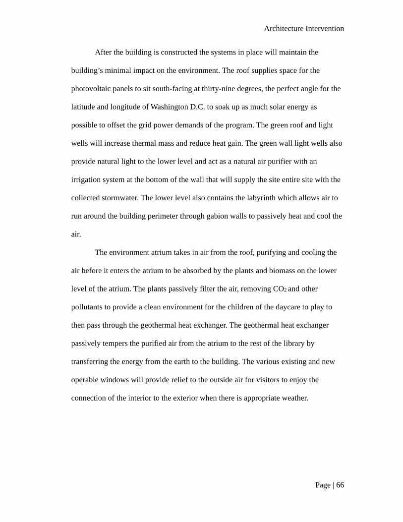
Architecture Intervention
Page | 66
After the building is constructed the systems in place will maintain the
building’s minimal impact on the environment. The roof supplies space for the
photovoltaic panels to sit south-facing at thirty-nine degrees, the perfect angle for the
latitude and longitude of Washington D.C. to soak up as much solar energy as
possible to offset the grid power demands of the program. The green roof and light
wells will increase thermal mass and reduce heat gain. The green wall light wells also
provide natural light to the lower level and act as a natural air purifier with an
irrigation system at the bottom of the wall that will supply the site entire site with the
collected stormwater. The lower level also contains the labyrinth which allows air to
run around the building perimeter through gabion walls to passively heat and cool the
air.
The environment atrium takes in air from the roof, purifying and cooling the
air before it enters the atrium to be absorbed by the plants and biomass on the lower
level of the atrium. The plants passively filter the air, removing CO2 and other
pollutants to provide a clean environment for the children of the daycare to play to
then pass through the geothermal heat exchanger. The geothermal heat exchanger
passively tempers the purified air from the atrium to the rest of the library by
transferring the energy from the earth to the building. The various existing and new
operable windows will provide relief to the outside air for visitors to enjoy the
connection of the interior to the exterior when there is appropriate weather.

Conclusion
Page | 67
Chapter 8 Conclusion
As it becomes more apparent how we have been negatively impacting our
planet, we need to take a step back and evaluate how new methods of sustainable
design can be incorporated into the existing built environment to leave a positive
impression on our climate. Just as the United Nations Environment Program’s 2019
Global Status Report states that buildings and construction were responsible for
thirty-six percent of final energy use and thirty-nine percent of energy and process-
related CO2 emissions in 2018, with eleven percent of these emissions resulting from
the manufacturing process of building materials and products such as steel and
concrete,36 we as designers should be looking for new methods of construction that
can cut down on the impact of buildings and construction. This thesis offers a solution
36 (2019), IEA and UNEP (United Nations Environment Programme). 2019. 2019 Global
Status Report for Buildings and Construction. Global Alliance for Buildings and Construction, UN Environment and the International Energy Agency. Accessed May 16, 2020.
Figure 82: Southwest Axon (Source: Author)
Conclusion
Page | 68
to the amount of demolition that occurs annually in the United States because of the
alarming fact that America’s built environment creates over half a billion tons of
debris annually with ninety percent of the built environment debris coming from
demolition.37
This thesis asks the question of why we continue to build, demo, and then
rebuild when studies have shown that it can take up to eighty years for a building’s
operating efficiency to make up for the impact of the building’s construction
process.38 Instead of demoing existing structures that maintain embodied energy to be
replaced with a new structure with new embodied energy, we can adapt these spaces
to bring new life to the structures while also maintaining the history of the site. This
thesis illustrates how existing building materials can be used to cut down on the
environmental impact of construction by using natural construction materials like
mass timber to produce less greenhouse gas emissions during the construction process
and structure’s life cycle. These methods will allow the building to leave a larger,
healthier impact on our climate while also maintaining the history and culture of an
existing structure.
The site of the thesis became a great example of how existing buildings can be
adapted to not only act as a sustainable construction method but because of its
location in an area that has seen rapid development in recent years, the proposed
project shows how maintaining an existing structure can remind a community of its
37 IEA and UNEP (United NationsEnvironment Programme). 2019. 2019 Global Status
Report for Buildings and Construction. Global Alliance for Buildings and Construction, UN Environment and the International Energy Agency. Accessed May 16, 2020.
38 Kerr, Warren, ed. 2004. "Adaptive Reuse. Preserving Our Past, Building Our Future." Austrialian Government Department of the Environment and Heritage. Commonwealth of Australia. Accessed October 6, 2019.

Conclusion
Page | 69
past. The solution of this thesis stands as the heart of a community that is in dire need
of a space to claim as their own by embracing an existing building that has sat as a
vacant for many years, bringing new life to the structure and the site to stand as a
reminder of the community’s thriving industrial past. I believe that an important part
of a community’s identity is remembering the past in a way that can influence a better
future. The solution provided by this thesis shows just one example of how we can
adapt our existing structures to not only maintain this sense of identity but use
sustainable methods to cut down on the impact buildings and construction have on
our environment, the place we call home.
Figure 83: Perspective illustrating the relationship between the two buildings (Source: Author)

Conclusion
Page | 70
Bibliography
Kerr, Warren, ed. 2004. "Adaptive Reuse. Preserving Our Past, Building Our Future."
Australian Government Department of the Environment and Heritage.
Commonwealth of Australia. Accessed October 6, 2019.
https://www.environment.gov.au/system/files/resources/3845f27a-ad2c-4d40-
8827-18c643c7adcd/files/adaptive-reuse.pdf.
American Wood Council. n.d. Mass Timber in North America: Expanding the
possibilities of wood building design. reThink Wood. Accessed October 13,
2019. https://www.awc.org/pdf/education/des/ReThinkMag-DES610A-
MassTimberinNorthAmerica-161031.pdf.
Butler Square | Minneapolis Office Space. n.d. Butler Square. Accessed November
12, 2019. https://www.butlersquare.com/about.html.
Capitol Riverfront BID. 2019. Capitol Riverfront. Accessed November 11, 2019.
https://www.capitolriverfront.org.
2019. Climate Change Evidence: How Do We Know? NASA. September 30.
Accessed October 6, 2019. https://climate.nasa.gov/evidence/.
Contribution of Working Group I to the Fifth Assessment Report of the
Intergovernmental Panel on Climate Change [Stocker, T.F., D. Qin, G.-K.
Plattner, M. Tignor, S.K. Allen, J. Boschung, A. Nauels, Y. Xia, V. Bex and
P.M. Midgley (eds.)]. n.d. IPCC, 2013: Summary for Policymakers. In:
Climate Change 2013: The Physical Science Basis. Cambridge, United
Kingdom and New York, NY, USA: Cambridge University Press.
Cramer, Ned. 2017. "The Climate Is Changing. So Must Architecture." Architect
Magazine. October 4. Accessed October 6, 2019.
https://www.architectmagazine.com/design/editorial/the-climate-is-changing-
so-must-architecture_o.

Conclusion
Page | 71
Crow, James Mitchell. 2008. "The Concrete Conundrum." Chemistryworld.org.
March. Accessed October 6, 2019.
https://www.rsc.org/images/Construction_tcm18-114530.pdf.
District of Columbia Office of Planning. 2009. "District of Columbia Inventory of
Historic Sites." District of Columbia, 229. Accessed October 27, 2019.
https://web.archive.org/web/20090717032933/http://planning.dc.gov/planning
/frames.asp?doc=%2Fplanning%2Flib%2Fplanning%2Fpreservation%2Fhp_i
nventory%2Finventory_narrative_sep_2004.pdf.
Evan. 2016. "What Building Material (wood, steel, concrete) Has The Smallest
Overall Environment Impact?" Debating Science. University of
Massachusetts. April 21. Accessed October 6, 2019.
https://blogs.umass.edu/natsci397a-eross/what-building-material-wood-steel-
concrete-has-the-smallest-overall-environment-impact/.
Frank Lowenstein, Brian Donahue, and David Foster. 2019. "Let's Fill Our Cities
with Taller, Wooden Buildings." The New York Timer. October 3. Accessed
October 12, 2019. https://www.nytimes.com/2019/10/03/opinion/wood-
buildings-architecture-cities.
2003, edited June 2007. "Historic Preservation Design Guidelines for Development of
the Southeast Federal Center." Washington D.C. Office of Planning. Accessed
December 13, 2019.
IEA and UNEP (United NationsEnvironment Programme). 2019. 2019 Global Status
Report for Buildings and Construction. Global Alliance for Buildings and
Construction, UN Environment and the International Energy Agency.
Accessed May 16, 2020.
https://www.worldgbc.org/sites/default/files/2019%20Global%20Status%20R
eport%20for%20Buildings%20and%20Construction.pdf.
Igor Fracalossi and MSR Design. 2010. Urban Outfitters Corporate Campus / MSR
Design. ArchDaily. December 1. Accessed November 12, 2019.

Conclusion
Page | 72
https://www.archdaily.com/92989/urban-outfitters-corporate-campus-meyer-
scherer-rockcastle.
National Park Service U.S. Department of the Interior. n.d. Preservation as a
Treatment and Standards for Preservation-Technical Preservation Services,
National Park Service. Accessed December 10, 2019.
https://www.nps.gov/tps/standards/four-treatments/treatment-
preservation.htm.
National Parks Service. n.d. National Register of Historic Places FAQs. Accessed
December 12, 2019. https://www.nps.gov/subjects/nationalregister/faqs.htm.
2019. "Sustainability." Think Wood. Accessed October 13, 2019.
https://www.thinkwood.com/building-better/sustainability.
n.d. "The 2030 Commitment." aia.org. Accessed October 6, 2019.
https://www.aia.org/resources/202041-the-2030-commitment.
2019. The Cause of Climate Change. NASA. September 30. Accessed October 5,
2019. https://climate.nasa.gov/causes/.
Think Wood. n.d. Butler Square. Accessed November 12, 2019.
https://www.thinkwood.com/our-projects/butler-square.
Tingley D.D., Davison B. 2013. Minimizing the Environmental Impact of Steel
Structures. In: Jármai K., Farkas J. (eds) Design, Fabrication and Economy of
Metal Structures., Springer, Berlin, Heidelberg.
United States Department of the Interior National Park Service. April 2007 (updated
October 2007). National Register of Historic Places Registration Form.
United States Department of the Interior, Washington, D.C.: National Park
Service, 61. Accessed October 27, 2019.
https://planning.dc.gov/sites/default/files/dc/sites/op/publication/attachments/
Washington%20Navy%20Yard%20Annex%20HD%20nomination.pdf.

Conclusion
Page | 73
United States Environmental Protection Agency. 2020. Sustainable Management of
Construction and Demolition Materials. United States Environmental
Protection Agency. Accessed May 16, 2020.
https://www.epa.gov/smm/sustainable-management-construction-and-
demolition-materials.
Walsh, Niall Patrick. 2018. "6 Architectural Responses to Climate Change in 2018."
ArchDaily. December 4. Accessed October 6, 2019.
https://www.archdaily.com/907140/6-architectural-responses-to-climate-
change-in-2018.

Conclusion
Page | 74
Figure Reference
Figure 1: Historic Image of Butler Square from the local newspaper (Source:
https://www.butlersquare.com/photos) ......................................................................... 3
Figure 2: Heavy timber atrium (Source: Jenna Bauer via Thinkwood.com) ................ 3
Figure 3: Exterior view of Butler Square today (Source:
https://www.butlersquare.com/photos) ......................................................................... 4
Figure 4: Natural daylighting from atrium (Source Pete Sieger via Flickr.com) .......... 4
Figure 5: Historic Images of the Philadelphia Navy Yard as a ship building, repair,
and scrapping site (Source: MSRDesign) ..................................................................... 5
Figure 6: Exterior images of URBN campus (Source: top - Lara Swimmer
Photography & Bottom - MSR Design)........................................................................ 6
Figure 7: Interior images of MSR Design's adaptive reuse design (Source: MSR
Design) .......................................................................................................................... 6
Figure 8: Section throught the URBN campus (Source MSR Design) ......................... 7
Figure 9: Transformation of URBN buildings over the life of the Navy Yard (Source:
MSR Design via Arch Daily) ........................................................................................ 7
Figure 10: GoSpotCheck Headquarters set within the historic context of LoDo
(Source: Tryba Architects) ............................................................................................ 8
Figure 11: Elevation diagram illustrating the addition's relationship to the surrounding
historic context through scale, proportion, and radiating lines (Source: Tryba
Architects) ..................................................................................................................... 8
Figure 12: Interior image of the steel and glulam structure (Source: Tryba Architects)
....................................................................................................................................... 9

Conclusion
Page | 75
Figure 13: Interior of Quincy Hall at opening (Source: Smith, H.G.) .......................... 9
Figure 14 Activation of plaza space between Quincy Hall and South Market Building
(Source: flickr.com) .................................................................................................... 10
Figure 15: Break down of Quincy Market, South Market, and North Market program
types by average square feet, amount, and total square feet (Source: Author) ........... 10
Figure 16: Atmospheric CO2 Levels (Source: climate.nasa.gov) ................................ 11
Figure 17: Top: annual surface temperature change. Bottom: change in average
precipitation. (Source: IPCC 2013) ............................................................................. 12
Figure 18: Shanghai on its hottest day of recorded history at 105.6℉ (Source:
Architect Magazine) .................................................................................................... 13
Figure 19: Temperature change in the Continental United States since 1895 to 2018
(Source: The Washington Post) ................................................................................... 14
Figure 20: Construction of the Burj Khalifa and surrounding area. (Source: “The
Concrete Conundrum”) ............................................................................................... 15
Figure 21: Washington D.C. Navy Yard Neighborhood (Source: Author) ................. 18
Figure 22: Navy Yard District after World War II (Source: Google Earth) ................ 18
Figure 23: Map of the Navy Yard Neighborhood showing the Nationals Park, DOT
Complex, Navy Complex, and thesis site (Source: Author) ....................................... 19
Figure 24: Building 170 in September 2019 (Source: Author) ................................... 20
Figure 25: Building 170, the Boilermaker Shops, the Foundry Lofts, and the Lumber
Shed at the Yards Park in 2003 (Source: https://www.jdland.com/) .......................... 21
Figure 26: Building 170, the Boilermaker Shops, the Foundry Lofts, and the Lumber
Shed at the Yards Park in September 2004 (Source: https://www.jdland.com/) ......... 21

Conclusion
Page | 76
Figure 27: Site adjacent to DOT complex surrounded by new construction (Source:
Author) ........................................................................................................................ 22
Figure 28: Condition of Building in September 2019 (Source: Author) .................... 23
Figure 29: Interior of Building 170 (Source: Developer Kelly Silverman) ................ 24
Figure 30 Existing buildings of the Washington D.C. Navy Yard neighborhood
(Source: Author) .......................................................................................................... 25
Figure 31: Site Breakdown of Building 170 (Source: Author) ................................... 26
Figure 32: Sagamore Development's Master Plan for Port Covington (Source:
Baltimore Sun) ............................................................................................................ 27
Figure 33: Site Breakdown of Port Covington (Source: Author) ............................... 28
Figure 34: Site Breakdown of Alley-Eblana Brewery (Source: Author) .................... 29
Figure 35: Comparison of Building 170, Port Covington, and Alley-Eblana Brewery
(Source: Author) .......................................................................................................... 30
Figure 36: Site Matrix (Source: Author) ..................................................................... 30
Figure 37: Future land use of the Navy Yard neighborhood (Source: Author) ........... 32
Figure 38: Land use of the Navy Yard neighborhood (Source: Author) ..................... 32
Figure 39: Walking radius to Capital Bikeshare locations (Source: Author) .............. 33
Figure 40: Walking radius to bus stops (Source: Author) ........................................... 34
Figure 41: Walking radius to metro stops (Source: Author) ....................................... 34
Figure 42: Interior of the Wood Innovation and Design Centre (Source: Ema Peter via
Architecture Magazine) .............................................................................................. 40
Figure 43: Mass Timber Products Matrix (Source: Author) ....................................... 41
Figure 44: CLT board (Source: Technology in Architecture) ..................................... 41

Conclusion
Page | 77
Figure 45: DLT panel (Source: Meng Gong) .............................................................. 42
Figure 46: Glulam beam (Source: bimobject) ............................................................ 42
Figure 47: LVL (Source: Element Five) ..................................................................... 42
Figure 48: LSL (Source: European Wood) ................................................................. 43
Figure 49: NLT Panel (Source: Meng Gong) .............................................................. 43
Figure 50: Wood Concrete Composite (Source: Structure Craft) ............................... 43
Figure 51: Mjøsa tower. (Source: Nina Rundsveen via metalocus.es) ....................... 44
Figure 52: Lifecycle of mass timber construction (Source: Author) .......................... 45
Figure 53: CLT char illustration (Source: Think Wood, Edited by Author) ............... 46
Figure 54: John W. Oliver Design Building at UMass Amherst (Source: auburn.edu)
..................................................................................................................................... 47
Figure 55: Walking radius to local Libraries (Source: Author) .................................. 48
Figure 56: Termination of New Jersey Ave. SE, Tingey St. SE, and N St. SE at the site
(Source: Author) .......................................................................................................... 49
Figure 57: Existing Site Condition (Source: Author) ................................................. 50
Figure 58: Proposed Site Condition (Source: Author) ................................................ 50
Figure 59: Navy Yard Plaza facing Building 170 (Author: Source) ........................... 51
Figure 60: Proposed Site Plan highlighting historic urban elements (Source: Author)
..................................................................................................................................... 52
Figure 61: Perspective looking down New Jersey Ave. towards the site (Source:
Author) ........................................................................................................................ 53
Figure 62: Perspective of entrance off of New Jersey Ave. to the library portion of the
program (Source: Author) ........................................................................................... 53
Conclusion
Page | 78
Figure 63: 1st Floor Plan - illustration of program overview (Source: Author) ........ 54
Figure 64: Longitudinal Section - illustration of program (Source: Author) .............. 54
Figure 65: 1st Floor Plan (Source: Author)................................................................. 55
Figure 66: Perspective of food hall 1st floor program (Source: Author) .................... 56
Figure 67: Perspective showing reading stair on the 1st floor of the library program
(Source: Author) .......................................................................................................... 57
Figure 68: Lower Level Floor Plan (Source: Author) ................................................. 58
Figure 69:Perspective of the exterior space in the daycare provided by the
environment atrium (Source: Author) ......................................................................... 58
Figure 70: 2nd Floor Plan (Source: Author) ............................................................... 59
Figure 71: Perspective of the library stack areas (Source: Author) ............................ 59
Figure 72: Perspective of 2nd-floor terrace space that looks on to the Navy Yard Plaza
below (Source: Author) ............................................................................................... 60
Figure 73: Perspective of the 2nd level of the food hall (Source: Author) ................. 61
Figure 74: 3rd Floor Plan (Source: Author) ................................................................ 61
Figure 75: 4th Floor Plan (Source: Author) ................................................................ 62
Figure 76: Perspective of the top floor of the library and atrium glulam truss system
(Source: Author) .......................................................................................................... 62
Figure 77: left section - through existing; right section - through library (Source:
Author) ........................................................................................................................ 63
Figure 78: Exploded Axon (Source: Axon) ................................................................ 63
Figure 79: Elevation diagram illustrating the graphics of the perforated metal screens
(Source: Author) .......................................................................................................... 64
Conclusion
Page | 79
Figure 80: Left - Beam and Column Exploded Axon; Right - Atrium Truss and Roof
Structure Exploded Axon (Source: Author) ................................................................ 65
Figure 81: Sustainability Section (Source: Author) .................................................... 65
Figure 82: Southwest Axon (Source: Author) ............................................................. 67
Figure 83: Perspective illustrating the relationship between the two buildings (Source:
Author) ........................................................................................................................ 69